US8799633B2 - MAC filtering on ethernet PHY for wake-on-LAN - Google Patents
MAC filtering on ethernet PHY for wake-on-LAN Download PDFInfo
- Publication number
- US8799633B2 US8799633B2 US13/025,818 US201113025818A US8799633B2 US 8799633 B2 US8799633 B2 US 8799633B2 US 201113025818 A US201113025818 A US 201113025818A US 8799633 B2 US8799633 B2 US 8799633B2
- Authority
- US
- United States
- Prior art keywords
- mac address
- block
- ephy
- network controller
- main network
- Prior art date
- Legal status (The legal status is an assumption and is not a legal conclusion. Google has not performed a legal analysis and makes no representation as to the accuracy of the status listed.)
- Active, expires
Links
Images


Classifications
-
- G—PHYSICS
- G06—COMPUTING; CALCULATING OR COUNTING
- G06F—ELECTRIC DIGITAL DATA PROCESSING
- G06F1/00—Details not covered by groups G06F3/00 - G06F13/00 and G06F21/00
- G06F1/26—Power supply means, e.g. regulation thereof
- G06F1/32—Means for saving power
- G06F1/3203—Power management, i.e. event-based initiation of a power-saving mode
- G06F1/3206—Monitoring of events, devices or parameters that trigger a change in power modality
- G06F1/3209—Monitoring remote activity, e.g. over telephone lines or network connections
-
- G—PHYSICS
- G06—COMPUTING; CALCULATING OR COUNTING
- G06F—ELECTRIC DIGITAL DATA PROCESSING
- G06F1/00—Details not covered by groups G06F3/00 - G06F13/00 and G06F21/00
- G06F1/26—Power supply means, e.g. regulation thereof
- G06F1/32—Means for saving power
-
- H—ELECTRICITY
- H04—ELECTRIC COMMUNICATION TECHNIQUE
- H04L—TRANSMISSION OF DIGITAL INFORMATION, e.g. TELEGRAPHIC COMMUNICATION
- H04L12/00—Data switching networks
- H04L12/02—Details
- H04L12/12—Arrangements for remote connection or disconnection of substations or of equipment thereof
-
- Y—GENERAL TAGGING OF NEW TECHNOLOGICAL DEVELOPMENTS; GENERAL TAGGING OF CROSS-SECTIONAL TECHNOLOGIES SPANNING OVER SEVERAL SECTIONS OF THE IPC; TECHNICAL SUBJECTS COVERED BY FORMER USPC CROSS-REFERENCE ART COLLECTIONS [XRACs] AND DIGESTS
- Y02—TECHNOLOGIES OR APPLICATIONS FOR MITIGATION OR ADAPTATION AGAINST CLIMATE CHANGE
- Y02D—CLIMATE CHANGE MITIGATION TECHNOLOGIES IN INFORMATION AND COMMUNICATION TECHNOLOGIES [ICT], I.E. INFORMATION AND COMMUNICATION TECHNOLOGIES AIMING AT THE REDUCTION OF THEIR OWN ENERGY USE
- Y02D30/00—Reducing energy consumption in communication networks
- Y02D30/50—Reducing energy consumption in communication networks in wire-line communication networks, e.g. low power modes or reduced link rate
Definitions
- This invention relates generally to computer networking and, more particularly, to the design of media access control (MAC) filtering on Ethernet physical layer (PHY).
- MAC media access control
- PHY Ethernet physical layer
- Ethernet is the IEEE 802.3 series standard, originally based on the Carrier Sense Multiple Access with Collision Detection (CSMA/CD) method that provided a means for two or more computer stations to share a common cabling system.
- CSMA/CD Carrier Sense Multiple Access with Collision Detection
- CSMA/CD has formed the basis for Ethernet systems that reached transfer speeds in the megabit range, that is the Mbit/sec range.
- Recent switched based and/or router based Ethernet systems are capable of supporting transfer rates in the Gbit/sec range.
- Ethernet generally makes efficient use of shared resources, is typically easy to reconfigure and maintain, and provides compatibility across many manufacturers and systems, while keeping the cost low.
- the Ethernet defines a number of wiring and signaling standards for the physical layer (PHY), through means of network access at the Media Access Control (MAC)/Data Link Layer, and through a common addressing format.
- Ethernet enabled devices typically communicate by transmitting data packets, which comprise blocks of data that are individually sent and delivered.
- each Ethernet station is given a single 48-bit MAC address, which is used both to specify the destination and the source of each data packet.
- the MAC data communication protocol sub-layer is a sub-layer of the data link layer specified in the seven-layer OSI (Open System Interconnect) model (layer 2), and acts as an interface between the Logical Link Control (LLC) sub-layer and the network's physical layer. It emulates a full-duplex logical communication channel in a multipoint network to provide addressing and channel access control mechanisms that make it possible for several terminals or network nodes to communicate within a multipoint network, typically a LAN or a WAN.
- OSI Open System Interconnect
- Wake-on-LAN is an Ethernet-based computer networking standard developed to turn on or wake up computers through a network packet.
- the wake up packet is typically transmitted by a program that is executed on another computer on the same LAN.
- a supplementary standard called Wake on Wireless LAN (WoWLAN) is employed to remotely wake up the computer.
- the WOL and WoWLAN standards are often supplemented by vendors to provide protocol-transparent on-demand services.
- WOL support is typically implemented on the motherboard (e.g. in the BIOS) of a computer and the network interface (firmware), and is therefore operating system independent. Some operating systems, however, can control WOL behaviour via hardware drivers. Motherboards with an embedded Ethernet controller that supports WOL do not require cable connections, but if the network interface is a plug-in card rather than an integrated feature on the motherboard, the plug-in card may need to be connected to the motherboard by a cable.
- WOL is implemented by transmitting a special packet referred to as “a magic packet” uniquely defined for the purpose of waking up the computer.
- the magic packet contains the MAC address of the destination computer, which the listening computer can identify to recognize that a magic packet is addressed to it.
- the destination computer Upon receipt of the magic packet and having recognized the MAC address, the destination computer initiates system wake-up.
- the magic packet is sent on the data link layer and broadcast to all network interface controllers (NICs), which may be separate interface cards or may be built in on the motherboard, using the network broadcast address.
- NICs network interface controllers
- the WOL feature is platform-independent. In order for WOL to work properly, at least certain portions of the network interface circuitry are required to remain turned on in order to detect a magic packet, thereby consuming standby power. If WOL is not required, disabling it may reduce power consumption slightly while the computer is switched off but remains plugged into power.
- the magic packet is typically a broadcast frame containing six bytes all having a value of 255 (FFFFFFFFFF in hexadecimal) anywhere within its payload, followed by sixteen repetitions of the target computer's 48-bit MAC address. Since the magic packet is only scanned for the above string, and not parsed by a full protocol stack, it may be sent as any network-layer and transport-layer protocol. Magic packets are typically sent as UDP datagrams to port 7 or port 9 , but they may be targeting any of the available ports.
- Standard magic packets require a destination computer MAC address, they do not provide a delivery confirmation, they may not work outside the LAN, and they may require hardware support of WOL on the destination computer, as the WOL implementation is designed to be simple and is intended for quick processing by the NIC circuitry, with minimal power requirement. Since WOL operates below the protocol layer, the MAC address is required, and WOL may not be performed using IP addresses and/or DNS names.
- a Media Access Control (MAC) address filtering function may be implemented on an Ethernet physical layer (ePHY), for example on a 10/100 ePHY.
- the filtering function on the ePHY performs the MAC address comparison between the MAC address identifying the given computer and the incoming MAC address contained in the magic packet transmitted onto the LAN connection infrastructure, e.g. an Ethernet network connection.
- a MAC address on a system-on-chip (SoC) within the computer may be matched with the MAC address contained in the incoming WOL packet frame.
- SoC system-on-chip
- Performing the MAC address comparison within the ePHY allows the main system components, such as the main SOC and other components to remain in standby mode (or sleep mode) until a MAC address match has been determined. Therefore, the main system components do not need to be rebooted every time the device receives a WOL frame, only when there is a match between the MAC address of the system and the MAC address contained in the detected WOL packet.
- an internal register within the ePHY on a network interface controller may store the MAC address identifying the SOC (or computer).
- the SOC may write its MAC address into the internal register on the ePHY of the NIC.
- the main SOC and all peripheral large-scale integrated (LSI) circuitry may enter a standby mode, except for the ePHY of the NIC, which may remain turned on to wait for WOL packet frames received by the ePHY.
- the ePHY may detect the package frame, and perform the MAC address comparison to determine if there is a match.
- the ePHY may generate an interrupt (INT) signal to an external boot processing unit (e.g. an external boot CPU) to start boot the system.
- an external boot processing unit e.g. an external boot CPU
- the SOC computer may proceed and reboot without having to identify and match the received MAC address, and may remain in standby mode if the ePHY has determined that the MAC address in the magic packet does not match the MAC address associated with the SOC.
- a device having a device address may include one or more primary device components configured to enter a low power mode when so instructed, and may also include a network connectivity physical layer (PHY) block to couple the device to a network.
- the PHY may also detect over the network a first packet comprising a target address, even when the one or more primary components of the device are in the low-power mode, with the first packet intended to wake up a target device associated with the target address.
- the one or more primary components of the device may include an SOC that includes a MAC block, with the device address being a MAC address.
- the PHY block may be an Ethernet PHY block that includes a MAC filter module to compare the target address with the device address.
- the PHY may compare the target address with the device address, and initiate a process instructing the one or more primary device components to exit the low power mode if the one or more primary device components are in the low power mode and the comparison indicates that the target address matches the device address.
- FIG. 1 shows a high-level system diagram of one embodiment of a local area network (LAN) coupling multiple devices having Wake-on-LAN (WOL) capabilities;
- LAN local area network
- WOL Wake-on-LAN
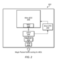
- FIG. 2 shows a functional block diagram of one embodiment of a computer that can perform a WOL function
- FIG. 3 shows a functional block diagram of one embodiment of a computer that can perform a WOL function without requiring waking up the main system upon receipt of a magic packet;
- FIG. 4 shows a flow chart illustrating operation of a device exemplified in FIG. 2 , upon receiving a WOL packet frame;
- FIG. 5 shows a flow chart illustrating operation of a device exemplified in FIG. 3 , upon receiving a WOL packet frame
- FIG. 6 shows a table highlighting the benefits of performing media access control (MAC) address filtering in an Ethernet physical layer (ePHY).
- MAC media access control
- Wake-On-LAN is mandatory function in Digital Television (DTV), Digital Video Recorder (DVR), Printer and other Consumer Electronic (CE) products for power saving during system standby.
- system standby mode or sleep mode refers to any low-power mode, which the device might enter upon being so instructed, to conserve energy and power.
- a system standby or device standby refers to a main system block and/or associated components of the system/device residing in the low-power mode, while select, but few, components within the system/device may remain operational.
- a printer may be considered in full sleep mode, when with the exception of an Ethernet physical layer (ePHY) block and/or a secondary (boot) processing unit, all components within the printer reside in low-power mode.
- ePHY Ethernet physical layer
- boot secondary
- FIG. 1 shows one embodiment of a LAN 100 built around an Ethernet-based network connection 102 , and devices connected to network connection 102 .
- Connected devices may include a personal computer 104 , network router 106 , printer 108 , digital television (DTV) 110 , and Blu-Ray/DVD player 112 .
- DTV digital television
- LAN 100 is shown for illustration purposes, and in alternate embodiments, fewer or additional devices may be connected to network connection 102 .
- network connection 102 may also be a wireless connection or a WiFi connection, or any connection suitable for connecting devices together into a network, or LAN.
- each device that supports WOL functionality may include a media access control (MAC) address block and a physical (PHY) block for detecting the magic packets transmitted over network connection 102 as part of a WOL transmission, recognizing the magic packets, and determining which device the WOL instruction is intended for.
- personal computer 104 may generate and transmit a magic packet intended to wake up printer 108 onto network connection 102 .
- a PHY block within printer 108 may perform detection of the WOL packet frame, and a MAC block within printer 108 may perform an address comparison to determine if its MAC address and the MAC address in the incoming WOL packet is the same. Once the MAC addresses have been matched, printer 108 may proceed to wake up from sleep mode.
- the MAC block may be typically integrated into the main SOC or processing block of the connected device/computer. Consequently, the main SOC in that device may need to wake up, or reboot from standby mode in order to detect the WOL upon receipt of a magic packet, and compare its MAC address with the MAC address contained in the WOL packet to determine which device the magic packet was intended for. While the WOL feature is meant to allow a main SOC to enter sleep mode in order to save power, the SOC cannot remain in sleep mode at all times if it supports WOL. More specifically, every time a magic packet is transmitted to the LAN network connection 102 , the main SOC in each device needs to exit sleep mode to acknowledge the packet, and make the MAC address comparison.
- the SOC in general is meant to refer to the main circuitry and/or system circuitry within a given device. In other words, it may refer to an SOC, or an SOC in combination with other circuitry on a motherboard, or any other primary system circuitry that is to reside in a reduced power mode (e.g. sleep mode) when not in use, i.e. when not waken up.
- a reduced power mode e.g. sleep mode
- each of the devices connecting to network connection 102 and supporting WOL needs to recognize and process a magic packet, when the Ethernet physical layer (ePHY) within the device receives a magic packet.
- the respective SOC within each device needs to wake up, regardless of which of the attached devices the magic packet is targeting.
- One possible way of solving this issue is by incorporating a boot CPU separate from the main SOC (i.e. separate from the main CPU of the system), having an interrupt (INT) pin, and signaling the boot CPU via this interrupt pin to instruct the boot CPU that the ePHY has received a WOL packet frame.
- INT interrupt
- Device 200 shown in 2 may represent any of the devices coupling to network connection 102 , as shown in FIG. 1 .
- Device 200 may couple to network connection 102 via an RJ45 connector 210 , interfacing with the ePHY layer 206 via magnetic coupling 208 .
- the ePHY layer interfaces with the MAC layer 204 within main SOC 202 .
- ePHY layer may transmit an interrupt to boot CPU 212 via the INT pin of boot CPU 212 .
- boot CPU 212 may instruct main SOC 202 to perform a MAC address comparison to determine whether the incoming magic packet contains the MAC address in MAC layer 204 identifying device 200 , which would indicate that the WOL was intended for device 200 . If the MAC address in the incoming packet frame is a match for the MAC address in MAC layer 204 , SOC 202 may remain in operational mode. If the MAC address in the incoming packet frame is not a match with the MAC address in MAC layer 204 , SOC 202 may enter standby mode, and may eventually return to sleep mode, while ePHY 206 remains in a wake up state, i.e. in operational mode.
- the solution described above not only requires a boot sequence for main SOC 202 , but also for the entire device to power on for the sole purpose of matching the MAC address in MAC 204 of main SOC 202 with the MAC address contained in the received magic packet.
- device 200 represents DTV 102 from FIG. 1
- the whole DTV 102 may need to power on just to perform the MAC address comparison.
- the ePHY layer within DTV 102 detects a WOL frame—i.e. it receives and detects a magic packet—DTV 102 has to wake up to check the WOL frame before ascertaining if the WOL was even intended for DTV 102 .
- DTV 102 has to power down and enter standby/sleep mode again. This may result in DTV 102 to frequently wake up and power down for WOL detection, leading to additional power consumption, in addition to placing additional software requirements on DTV 102 .
- a MAC filtering function may be included in ePHY layer 206 to perform the MAC address comparison between the MAC address in MAC layer 204 within SOC 202 , and the MAC address contained in the incoming WOL packet frame.
- FIG. 3 A partial block diagram of one embodiment of such a device is shown in FIG. 3 .
- Device 200 shown in FIG. 3 may represent any of the devices coupling to network connection 102 , as shown in FIG. 1 .
- Device 300 may couple to network connection 102 via an RJ45 connector 312 , interfacing with the ePHY layer 308 via magnetic coupling 310 .
- the ePHY layer 308 interfaces with the MAC layer 304 within main SOC 302 . As shown in FIG.
- ePHY layer 308 may store the SOC's MAC address in an internal register within MAC filtering block (MFB) 306 .
- MFB MAC filtering block
- SOC 302 may write its MAC address into the internal register within MFB 306 inside ePHY 308 .
- Main SOC 302 and all peripheral LSI circuitry within device 300 may enter into standby mode (or sleep mode), with the exception of ePHY 308 , which may remain operational to detect WOL packet frames, or magic packets.
- MFB 306 inside ePHY 308 may perform the MAC address comparison, and may only generate the interrupt to boot CPU 314 if the MAC address in the magic packet matches the MAC address stored in MFB 306 .
- main SOC 302 and the peripheral LSI circuitry in device 300 will be instructed to wake up only in case ePHY 308 has confirmed that the WOL transmitted through the detected magic packet is intended for device 300 .
- Operation of a device—exemplified by device 200 in FIG. 2 —upon receiving a WOL packet frame (or magic packet) may be characterized by the sequence shown in flowchart 400 in FIG. 4 .
- the ePHY block within the device e.g. ePHY 206
- the ePHY block may detect a magic packet, or WOL frame ( 402 ).
- the ePHY block Upon detecting the WOL frame, the ePHY block asserts an interrupt signal to the boot CPU ( 404 ).
- the boot CPU e.g. boot CPU 212
- main SOC e.g. main SOC 202
- reboot itself e.g. main SOC 202
- the main SOC (and firmware) then reboot ( 408 ), and the MAC block in the main SOC performs the MAC address comparison ( 410 ). If the comparison indicates that the MAC address of the main SOC matches the MAC address in the WOL frame (“Yes” branch of 412 ), a system wide reboot is performed, and the entire system enters operational mode ( 414 ). On the other hand, if the comparison indicates that the MAC address of the main SOC does not match the MAC address in the WOL frame (“No” branch of 412 ), the main SOC returns to standby (sleep) mode ( 416 ).
- operation of a device—exemplified by device 300 in FIG. 3 —upon receiving a WOL packet frame (or magic packet) may be characterized by the sequence shown in flowchart 500 in FIG. 5 .
- the main SOC e.g. main SOC 302
- the ePHY block within the device e.g. ePHY 308
- the MAC Filtering block e.g. MFB 306
- the MAC Filtering block performs the MAC address comparison ( 506 ).
- the ePHY block asserts an interrupt signal to the boot CPU ( 510 ).
- the boot CPU e.g. boot CPU 314
- main SOC performs the system boot up sequence ( 512 ).
- the system boot up sequence is then performed ( 514 ), and the system is now in operational mode, as instructed by the WOL frame.
- the comparison indicates that the MAC address of the main SOC does not match the MAC address in the WOL frame (“No” branch of 508 )
- the main SOC and most system elements remain in standby (sleep) mode ( 516 ).
- Table 600 in FIG. 6 summarizes the differences between the operating modes illustrated in FIGS. 4 and 5 , as associated with device 200 and device 300 , respectively.
- the sequence shown in FIG. 5 provides an efficient way of avoiding frequent reboots by the system/device.
- the operation illustrated in FIG. 5 requires fewer steps each time a WOL frame/packet is detected by the device.
- the entire system 100 shown in FIG. 1 may benefit from devices 104 - 112 performing WOL according to the operation illustrated by flowchart 500 .
- a user may initiate a print job to networked printer 108 from computer 104 .
- Computer 104 may consequently generate a WOL packet frame to wake up printer 108 and execute the print job.
- Computer 104 may then transmit the WOL packet containing the MAC address of printer 108 onto Ethernet network connection 102 .
- Devices 106 - 112 may all be in standby/sleep mode, when receiving the WOL packet frame.
- the ePHY within digital television (DTV) 110 may detect the WOL packet, and perform the MAC address comparison. Because the MAC addresses don't match, DTV 110 may remain in full sleep mode.
- the ePHY within Blu-Ray/DVD player 112 may also detect the WOL packet, and perform the MAC address comparison. Because the MAC addresses don't match, Blu-Ray/DVD player 112 may also remain in full sleep mode.
- the ePHY within printer 108 may also detect the WOL packet, and perform the MAC address comparison.
- the ePHY may initiate a boot up of printer 108 , which may boot up and/or exit sleep/standby mode, and execute the print job.
- additional devices such as a set-top box, a digital video recorder, a video game console, or any other networkable devices may also be coupled to Ethernet based network 102 .
- other computers may also be coupled to network connection 102 , configured to enter standby mode similar to other devices, where one attached computer may attempt to wake up another attached computer through a WOL packet, according to the operating principles described herein.
Abstract
Description
Claims (19)
Priority Applications (6)
| Application Number | Priority Date | Filing Date | Title |
|---|---|---|---|
| US13/025,818 US8799633B2 (en) | 2011-02-11 | 2011-02-11 | MAC filtering on ethernet PHY for wake-on-LAN |
| KR1020137023097A KR101852461B1 (en) | 2011-02-11 | 2012-01-20 | Mac filtering on ethernet phy for wake-on-lan |
| PCT/US2012/021992 WO2012108995A1 (en) | 2011-02-11 | 2012-01-20 | Mac filtering on ethernet phy for wake-on-lan |
| EP12702117.8A EP2673919B1 (en) | 2011-02-11 | 2012-01-20 | Mac filtering on ethernet phy for wake-on-lan |
| CN201280011973.4A CN103733565B (en) | 2011-02-11 | 2012-01-20 | Method and system for storing, controlling and filtering of media on ethernet physical layer for wake-on-lan |
| TW101104227A TWI524714B (en) | 2011-02-11 | 2012-02-09 | Mac filtering on ethernet phy for wake-on-lan |
Applications Claiming Priority (1)
| Application Number | Priority Date | Filing Date | Title |
|---|---|---|---|
| US13/025,818 US8799633B2 (en) | 2011-02-11 | 2011-02-11 | MAC filtering on ethernet PHY for wake-on-LAN |
Publications (2)
| Publication Number | Publication Date |
|---|---|
| US20120210112A1 US20120210112A1 (en) | 2012-08-16 |
| US8799633B2 true US8799633B2 (en) | 2014-08-05 |
Family
ID=45561122
Family Applications (1)
| Application Number | Title | Priority Date | Filing Date |
|---|---|---|---|
| US13/025,818 Active 2032-01-19 US8799633B2 (en) | 2011-02-11 | 2011-02-11 | MAC filtering on ethernet PHY for wake-on-LAN |
Country Status (6)
| Country | Link |
|---|---|
| US (1) | US8799633B2 (en) |
| EP (1) | EP2673919B1 (en) |
| KR (1) | KR101852461B1 (en) |
| CN (1) | CN103733565B (en) |
| TW (1) | TWI524714B (en) |
| WO (1) | WO2012108995A1 (en) |
Cited By (5)
| Publication number | Priority date | Publication date | Assignee | Title |
|---|---|---|---|---|
| US20130191663A1 (en) * | 2012-01-20 | 2013-07-25 | Cisco Technology, Inc. | System and method to conserve power in an access network without loss of service quality |
| US20150212562A1 (en) * | 2014-01-29 | 2015-07-30 | Sercel | Method for waking up a distant device from a local device |
| US9958924B2 (en) | 2013-08-28 | 2018-05-01 | Cisco Technology, Inc. | Configuration of energy savings |
| WO2021183987A1 (en) * | 2020-03-13 | 2021-09-16 | Texas Instruments Incorporated | Receiver synchronization |
| US11775045B2 (en) | 2019-06-13 | 2023-10-03 | Microchip Technology Incorporated | Managing power at a station via a physical layer device and related systems, methods and devices |
Families Citing this family (25)
| Publication number | Priority date | Publication date | Assignee | Title |
|---|---|---|---|---|
| JP5852320B2 (en) * | 2011-04-13 | 2016-02-03 | キヤノン株式会社 | Image forming apparatus and control method thereof |
| US9491032B2 (en) | 2013-05-29 | 2016-11-08 | Microsoft Technology Licensing, Llc | Pattern coalescing for remote wake-enabled applications |
| JP6088959B2 (en) * | 2013-10-31 | 2017-03-01 | 京セラドキュメントソリューションズ株式会社 | Electronics |
| TWI510910B (en) * | 2013-11-11 | 2015-12-01 | Wistron Corp | Computer system and remote control method thereof |
| US9236909B2 (en) | 2013-12-19 | 2016-01-12 | Stmicroelectronics, Inc. | Zero standby power for powerline communication devices |
| US10652168B2 (en) * | 2014-01-08 | 2020-05-12 | Hewlett Packard Enterprise Development Lp | Packet inspection to determine destination node |
| JP6291983B2 (en) * | 2014-04-08 | 2018-03-14 | 株式会社リコー | Recovery device and recovery method |
| US9391924B2 (en) * | 2014-07-25 | 2016-07-12 | Innovasic, Inc. | Ethernet interface module |
| WO2016068848A1 (en) * | 2014-10-27 | 2016-05-06 | Hewlett Packard Development Company, L.P. | Disregarding input in wake-on-lan boot |
| KR20160055446A (en) * | 2014-11-10 | 2016-05-18 | 삼성전자주식회사 | Display apparatus and Method for controlling the display apparatus thereof |
| US20160187955A1 (en) * | 2014-12-25 | 2016-06-30 | Ricoh Company, Limited | Information processing apparatus, information processing method and computer program product |
| US20160197736A1 (en) * | 2015-01-02 | 2016-07-07 | Cisco Technology, Inc. | Wake-On-Link |
| US9710045B2 (en) * | 2015-10-14 | 2017-07-18 | Quanta Computer Inc. | Managing network wake-up commands |
| CN107294876B (en) * | 2016-04-11 | 2020-12-04 | 联想企业解决方案(新加坡)有限公司 | Network switch for performing wake-on-LAN |
| WO2018086311A1 (en) * | 2016-11-10 | 2018-05-17 | 华为技术有限公司 | Method and device for waking up communication interface, identifier configuration method for auxiliary wake-up interface, and device |
| WO2018199908A1 (en) | 2017-04-24 | 2018-11-01 | Hewlett-Packard Development Company, L.P. | Configuration parameter transfer |
| CN111066374B (en) | 2017-07-18 | 2023-08-15 | 惠普发展公司,有限责任合伙企业 | System and method for device management |
| KR101986099B1 (en) * | 2018-01-05 | 2019-06-05 | (주)에프씨아이 | Method and Apparatus for Filtering for Reducing Wake-UP Frequency |
| US11057227B2 (en) * | 2018-10-02 | 2021-07-06 | Microsemi P.O.E Ltd. | Network management using wake on LAN |
| CN110568919B (en) * | 2019-09-09 | 2020-12-29 | 大唐半导体科技有限公司 | Device for reducing chip power consumption |
| GR1009900B (en) * | 2019-10-22 | 2021-01-12 | Νικολαος Αναστασιου Σφετσιος | Method and device for the remote start-up of devices suppporting the wake-up technology via a local network |
| US11924312B2 (en) | 2019-10-30 | 2024-03-05 | Microchip Technology Incorporated | EtherCAT controllers |
| CN111464377A (en) * | 2020-03-12 | 2020-07-28 | 苏州浪潮智能科技有限公司 | Network card inspection method, device, equipment and storage medium |
| CN112867108A (en) * | 2020-11-13 | 2021-05-28 | 深圳市泰和安科技有限公司 | Communication method and device |
| TWI763136B (en) * | 2020-11-20 | 2022-05-01 | 瑞昱半導體股份有限公司 | Methods for multidrop network system |
Citations (42)
| Publication number | Priority date | Publication date | Assignee | Title |
|---|---|---|---|---|
| US5598581A (en) | 1993-08-06 | 1997-01-28 | Cisco Sytems, Inc. | Variable latency cut through bridge for forwarding packets in response to user's manual adjustment of variable latency threshold point while the bridge is operating |
| WO1999065196A1 (en) | 1998-06-10 | 1999-12-16 | Merlot Communications, Inc. | Integrated voice and data communications over a local area network |
| US20010004768A1 (en) | 1998-09-28 | 2001-06-21 | Hodge Winston W. Hodge Winston W. | Highly integrated computer controlled digital head end |
| US20010005908A1 (en) | 1998-09-28 | 2001-06-28 | Hodge Winston W. | Method for buffering video, data and voice signals using a common shared bus |
| US20020007494A1 (en) | 1998-09-28 | 2002-01-17 | Hodge Winston W. | Interactive digital program material encoder and system |
| US20020015409A1 (en) | 2000-07-20 | 2002-02-07 | Wei Gao | Broadband Ethernet video data transmission |
| US20020019984A1 (en) | 2000-01-14 | 2002-02-14 | Rakib Selim Shlomo | Headend cherrypicker with digital video recording capability |
| US20020048258A1 (en) | 2000-10-16 | 2002-04-25 | Kazuya Oyama | Network communication method, network communication device and information device |
| US6385647B1 (en) | 1997-08-18 | 2002-05-07 | Mci Communications Corporations | System for selectively routing data via either a network that supports Internet protocol or via satellite transmission network based on size of the data |
| US20020059637A1 (en) | 2000-01-14 | 2002-05-16 | Rakib Selim Shlomo | Home gateway for video and data distribution from various types of headend facilities and including digital video recording functions |
| US20020087976A1 (en) | 2000-12-28 | 2002-07-04 | Kaplan Marc P. | System and method for distributing video with targeted advertising using switched communication networks |
| US20020091003A1 (en) | 2001-01-11 | 2002-07-11 | Beken Robert A. | Multi-player electronic entertainment system |
| US20020095681A1 (en) | 2001-01-16 | 2002-07-18 | Freddie Lin | Uncompressed IP multimedia data transmission and switching |
| US20020143996A1 (en) | 2001-03-29 | 2002-10-03 | Vic Odryna | Passive video multiplexing method and apparatus priority to prior provisional application |
| US20020147982A1 (en) | 1999-07-20 | 2002-10-10 | @Security Broadband Corp | Video security system |
| US6473441B1 (en) | 1998-12-18 | 2002-10-29 | Escient Convergence Corp | Multi-channel video pump |
| US20020161918A1 (en) | 2001-04-27 | 2002-10-31 | Fujitsu Limited Of Kawasaki, Japan | Packet transmission system in which packet is transferred without replacing address in the packet |
| US20020178274A1 (en) | 2001-03-06 | 2002-11-28 | Kovacevic Branko D. | System for digital stream transmission and method thereof |
| US20030050989A1 (en) | 2001-09-10 | 2003-03-13 | Digigram | Audio data transmission system between a master module and slave modules by means of a digital communication network |
| US20030061621A1 (en) | 2001-09-26 | 2003-03-27 | Micro Technology Services, Inc. | Transportable LAN-based surveillance system |
| US20030058885A1 (en) | 2001-09-18 | 2003-03-27 | Sorenson Donald C. | Multi-carrier frequency-division multiplexing (FDM) architecture for high speed digital service in local networks |
| US20030081131A1 (en) | 2001-10-26 | 2003-05-01 | Koninklijke Philips Electronics N.V. | Method for viewing and controlling multiple DVR's |
| US20030093563A1 (en) | 2001-10-10 | 2003-05-15 | Young Bruce Fitzgerald | Method and system for implementing and managing a multimedia access network device |
| US20030126294A1 (en) | 2001-11-19 | 2003-07-03 | Thorsteinson Thomas M. | Transmitting digital video signals over an IP network |
| US20030133456A1 (en) | 2002-01-11 | 2003-07-17 | Alcatel | Modem system and aggregator for paths with different transmission profiles |
| WO2003063425A1 (en) | 2002-01-18 | 2003-07-31 | Telefonaktiebolaget Lm Ericsson (Publ.) | Adaptive ethernet switch system and method |
| US6611531B1 (en) | 1998-09-30 | 2003-08-26 | Cisco Technology, Inc. | Method and apparatus for routing integrated data, voice, and video traffic |
| US20030163826A1 (en) | 2002-02-25 | 2003-08-28 | Sentrus, Inc. | Method and system for remote wireless video surveillance |
| US20030169314A1 (en) | 2002-03-05 | 2003-09-11 | Mcalonis Matthew R. | Connector assembly for printer ink cartridge |
| US6678740B1 (en) | 2000-01-14 | 2004-01-13 | Terayon Communication Systems, Inc. | Process carried out by a gateway in a home network to receive video-on-demand and other requested programs and services |
| US20040141461A1 (en) * | 2003-01-22 | 2004-07-22 | Zimmer Vincent J. | Remote reset using a one-time pad |
| JP2004336437A (en) | 2003-05-08 | 2004-11-25 | Matsushita Electric Ind Co Ltd | Circuit and system for video image receiving |
| JP2005341107A (en) | 2004-05-26 | 2005-12-08 | Matsushita Electric Ind Co Ltd | Packet transmitting/receiving apparatus |
| US7050440B2 (en) | 2000-11-24 | 2006-05-23 | International Business Machines Corporation | Method and structure for variable-length frame support in a shared memory switch |
| US20080219196A1 (en) | 2007-03-09 | 2008-09-11 | Henry Ptasinski | Infrastructure offload wake on wireless lan (wowl) |
| US20080270599A1 (en) | 2007-04-30 | 2008-10-30 | Eliezer Tamir | Method and system for configuring a plurality of network interfaces that share a physical interface |
| US20090241113A1 (en) | 2008-03-20 | 2009-09-24 | Seguin Jean-Marc L | Method and system for supporting wake-on-lan in a virtualized environment |
| US7680943B2 (en) | 2003-10-20 | 2010-03-16 | Transwitch Corporation | Methods and apparatus for implementing multiple types of network tunneling in a uniform manner |
| US20100218011A1 (en) | 2009-02-26 | 2010-08-26 | Broadcom Corporation | System and Method for Energy Savings Through Emulation of Wake on Lan in Energy Efficient Ethernet |
| US7840706B1 (en) | 2007-11-30 | 2010-11-23 | Nvidia Corporation | Wake-on-LAN design in a load balanced environment |
| US20110078299A1 (en) | 2009-09-04 | 2011-03-31 | Brocade Communications Systems, Inc. | Systems and Methods for Reconfiguring a Network Adapter in Sleep Mode |
| US8345673B1 (en) * | 2007-01-24 | 2013-01-01 | Marvell International, Ltd. | Physical-layer device (PHY) having a serial interface and a magic packet circuit |
Family Cites Families (2)
| Publication number | Priority date | Publication date | Assignee | Title |
|---|---|---|---|---|
| KR100756586B1 (en) * | 2006-02-10 | 2007-09-10 | 삼성전자주식회사 | Computer and control method thereof |
| TW201020750A (en) * | 2008-11-20 | 2010-06-01 | Inventec Corp | Thin client and thin client wake up method |
-
2011
- 2011-02-11 US US13/025,818 patent/US8799633B2/en active Active
-
2012
- 2012-01-20 KR KR1020137023097A patent/KR101852461B1/en active IP Right Grant
- 2012-01-20 WO PCT/US2012/021992 patent/WO2012108995A1/en active Application Filing
- 2012-01-20 CN CN201280011973.4A patent/CN103733565B/en active Active
- 2012-01-20 EP EP12702117.8A patent/EP2673919B1/en active Active
- 2012-02-09 TW TW101104227A patent/TWI524714B/en active
Patent Citations (43)
| Publication number | Priority date | Publication date | Assignee | Title |
|---|---|---|---|---|
| US5598581A (en) | 1993-08-06 | 1997-01-28 | Cisco Sytems, Inc. | Variable latency cut through bridge for forwarding packets in response to user's manual adjustment of variable latency threshold point while the bridge is operating |
| US6385647B1 (en) | 1997-08-18 | 2002-05-07 | Mci Communications Corporations | System for selectively routing data via either a network that supports Internet protocol or via satellite transmission network based on size of the data |
| WO1999065196A1 (en) | 1998-06-10 | 1999-12-16 | Merlot Communications, Inc. | Integrated voice and data communications over a local area network |
| US20010004768A1 (en) | 1998-09-28 | 2001-06-21 | Hodge Winston W. Hodge Winston W. | Highly integrated computer controlled digital head end |
| US20010005908A1 (en) | 1998-09-28 | 2001-06-28 | Hodge Winston W. | Method for buffering video, data and voice signals using a common shared bus |
| US20020007494A1 (en) | 1998-09-28 | 2002-01-17 | Hodge Winston W. | Interactive digital program material encoder and system |
| US6611531B1 (en) | 1998-09-30 | 2003-08-26 | Cisco Technology, Inc. | Method and apparatus for routing integrated data, voice, and video traffic |
| US6473441B1 (en) | 1998-12-18 | 2002-10-29 | Escient Convergence Corp | Multi-channel video pump |
| US20020147982A1 (en) | 1999-07-20 | 2002-10-10 | @Security Broadband Corp | Video security system |
| US20020019984A1 (en) | 2000-01-14 | 2002-02-14 | Rakib Selim Shlomo | Headend cherrypicker with digital video recording capability |
| US20040172658A1 (en) | 2000-01-14 | 2004-09-02 | Selim Shlomo Rakib | Home network for ordering and delivery of video on demand, telephone and other digital services |
| US20020059637A1 (en) | 2000-01-14 | 2002-05-16 | Rakib Selim Shlomo | Home gateway for video and data distribution from various types of headend facilities and including digital video recording functions |
| US6678740B1 (en) | 2000-01-14 | 2004-01-13 | Terayon Communication Systems, Inc. | Process carried out by a gateway in a home network to receive video-on-demand and other requested programs and services |
| US20020015409A1 (en) | 2000-07-20 | 2002-02-07 | Wei Gao | Broadband Ethernet video data transmission |
| US20020048258A1 (en) | 2000-10-16 | 2002-04-25 | Kazuya Oyama | Network communication method, network communication device and information device |
| US7050440B2 (en) | 2000-11-24 | 2006-05-23 | International Business Machines Corporation | Method and structure for variable-length frame support in a shared memory switch |
| US20020087976A1 (en) | 2000-12-28 | 2002-07-04 | Kaplan Marc P. | System and method for distributing video with targeted advertising using switched communication networks |
| US20020091003A1 (en) | 2001-01-11 | 2002-07-11 | Beken Robert A. | Multi-player electronic entertainment system |
| US20020095681A1 (en) | 2001-01-16 | 2002-07-18 | Freddie Lin | Uncompressed IP multimedia data transmission and switching |
| US20020178274A1 (en) | 2001-03-06 | 2002-11-28 | Kovacevic Branko D. | System for digital stream transmission and method thereof |
| US20020143996A1 (en) | 2001-03-29 | 2002-10-03 | Vic Odryna | Passive video multiplexing method and apparatus priority to prior provisional application |
| US20020161918A1 (en) | 2001-04-27 | 2002-10-31 | Fujitsu Limited Of Kawasaki, Japan | Packet transmission system in which packet is transferred without replacing address in the packet |
| US20030050989A1 (en) | 2001-09-10 | 2003-03-13 | Digigram | Audio data transmission system between a master module and slave modules by means of a digital communication network |
| US20030058885A1 (en) | 2001-09-18 | 2003-03-27 | Sorenson Donald C. | Multi-carrier frequency-division multiplexing (FDM) architecture for high speed digital service in local networks |
| US20030061621A1 (en) | 2001-09-26 | 2003-03-27 | Micro Technology Services, Inc. | Transportable LAN-based surveillance system |
| US20030093563A1 (en) | 2001-10-10 | 2003-05-15 | Young Bruce Fitzgerald | Method and system for implementing and managing a multimedia access network device |
| US20030081131A1 (en) | 2001-10-26 | 2003-05-01 | Koninklijke Philips Electronics N.V. | Method for viewing and controlling multiple DVR's |
| US20030126294A1 (en) | 2001-11-19 | 2003-07-03 | Thorsteinson Thomas M. | Transmitting digital video signals over an IP network |
| US20030133456A1 (en) | 2002-01-11 | 2003-07-17 | Alcatel | Modem system and aggregator for paths with different transmission profiles |
| WO2003063425A1 (en) | 2002-01-18 | 2003-07-31 | Telefonaktiebolaget Lm Ericsson (Publ.) | Adaptive ethernet switch system and method |
| US20030163826A1 (en) | 2002-02-25 | 2003-08-28 | Sentrus, Inc. | Method and system for remote wireless video surveillance |
| US20030169314A1 (en) | 2002-03-05 | 2003-09-11 | Mcalonis Matthew R. | Connector assembly for printer ink cartridge |
| US20040141461A1 (en) * | 2003-01-22 | 2004-07-22 | Zimmer Vincent J. | Remote reset using a one-time pad |
| JP2004336437A (en) | 2003-05-08 | 2004-11-25 | Matsushita Electric Ind Co Ltd | Circuit and system for video image receiving |
| US7680943B2 (en) | 2003-10-20 | 2010-03-16 | Transwitch Corporation | Methods and apparatus for implementing multiple types of network tunneling in a uniform manner |
| JP2005341107A (en) | 2004-05-26 | 2005-12-08 | Matsushita Electric Ind Co Ltd | Packet transmitting/receiving apparatus |
| US8345673B1 (en) * | 2007-01-24 | 2013-01-01 | Marvell International, Ltd. | Physical-layer device (PHY) having a serial interface and a magic packet circuit |
| US20080219196A1 (en) | 2007-03-09 | 2008-09-11 | Henry Ptasinski | Infrastructure offload wake on wireless lan (wowl) |
| US20080270599A1 (en) | 2007-04-30 | 2008-10-30 | Eliezer Tamir | Method and system for configuring a plurality of network interfaces that share a physical interface |
| US7840706B1 (en) | 2007-11-30 | 2010-11-23 | Nvidia Corporation | Wake-on-LAN design in a load balanced environment |
| US20090241113A1 (en) | 2008-03-20 | 2009-09-24 | Seguin Jean-Marc L | Method and system for supporting wake-on-lan in a virtualized environment |
| US20100218011A1 (en) | 2009-02-26 | 2010-08-26 | Broadcom Corporation | System and Method for Energy Savings Through Emulation of Wake on Lan in Energy Efficient Ethernet |
| US20110078299A1 (en) | 2009-09-04 | 2011-03-31 | Brocade Communications Systems, Inc. | Systems and Methods for Reconfiguring a Network Adapter in Sleep Mode |
Non-Patent Citations (7)
| Title |
|---|
| "Product Brief: TF-530 Digital TV Streaming Controller," taifatech: Optimizing Design Through ASIC, Taifatech, Inc., 2 pages. (Retrieved Oct. 24, 2004). |
| International Search Report and Written Opinion for Application No. PCT/US2006/000126 mailed Sep. 19, 2006, 7 pages. |
| International Search Report in Application No. PCT/US2012/021992 dated Mar. 14, 2012, 6 pages. |
| Official Action in Japanese Application No. 2006-018622 filed Jul. 1, 2008, 3 pages. |
| Taiwan Office Action, Application No. 101104227, 14 pages. |
| Taiwanese Patent Application TW 513635, published Dec. 11, 2002, 1 page, (abstract only). |
| Taiwanese Patent Office Search Report for Application No. 095102844, search completed May 26, 2008, 6 pages. |
Cited By (9)
| Publication number | Priority date | Publication date | Assignee | Title |
|---|---|---|---|---|
| US20130191663A1 (en) * | 2012-01-20 | 2013-07-25 | Cisco Technology, Inc. | System and method to conserve power in an access network without loss of service quality |
| US9141169B2 (en) * | 2012-01-20 | 2015-09-22 | Cisco Technology, Inc. | System and method to conserve power in an access network without loss of service quality |
| US9958924B2 (en) | 2013-08-28 | 2018-05-01 | Cisco Technology, Inc. | Configuration of energy savings |
| US10481665B2 (en) | 2013-08-28 | 2019-11-19 | Cisco Technology, Inc. | Configuration of energy savings |
| US20150212562A1 (en) * | 2014-01-29 | 2015-07-30 | Sercel | Method for waking up a distant device from a local device |
| US9588562B2 (en) * | 2014-01-29 | 2017-03-07 | Sercel | Method for waking up a distant device from a local device without waking up a physical layer unit in the distant device |
| US11775045B2 (en) | 2019-06-13 | 2023-10-03 | Microchip Technology Incorporated | Managing power at a station via a physical layer device and related systems, methods and devices |
| WO2021183987A1 (en) * | 2020-03-13 | 2021-09-16 | Texas Instruments Incorporated | Receiver synchronization |
| US11601302B2 (en) | 2020-03-13 | 2023-03-07 | Texas Instruments Incorporated | Receiver synchronization |
Also Published As
| Publication number | Publication date |
|---|---|
| WO2012108995A1 (en) | 2012-08-16 |
| KR101852461B1 (en) | 2018-04-27 |
| TW201244435A (en) | 2012-11-01 |
| CN103733565A (en) | 2014-04-16 |
| US20120210112A1 (en) | 2012-08-16 |
| CN103733565B (en) | 2017-04-12 |
| EP2673919A1 (en) | 2013-12-18 |
| KR20140065374A (en) | 2014-05-29 |
| TWI524714B (en) | 2016-03-01 |
| EP2673919B1 (en) | 2015-03-11 |
Similar Documents
| Publication | Publication Date | Title |
|---|---|---|
| US8799633B2 (en) | MAC filtering on ethernet PHY for wake-on-LAN | |
| US11665007B2 (en) | PoE powered device with link layer startup processor | |
| US7865748B2 (en) | Operating mode for extreme power savings when no network presence is detected | |
| US20050097378A1 (en) | Method and system for power management in a gigabit Ethernet chip | |
| US20080301322A1 (en) | Network controller, information processing apparatus and wake-up control method | |
| US20150082063A1 (en) | Baseboard management controller state transitions | |
| US20110107116A1 (en) | System and Method for Power Over Ethernet Enabled Network Management | |
| US7689819B2 (en) | Method and system for a self-booting Ethernet controller | |
| EP1401155B1 (en) | Method and system for wakeup packet detection at gigabit speeds | |
| US20050060587A1 (en) | Method and system for providing power management for an integrated gigabit Ethernet controller | |
| US7779195B2 (en) | Communication control apparatus for common bus connection devices | |
| US7924750B1 (en) | Method and apparatus for establishing a communication mode between network devices in a network | |
| JP3599048B2 (en) | Data transfer control system, electronic device, program, and data transfer control method | |
| US6742027B1 (en) | Data processing system and method for permitting a server to remotely disable a client computer system's input device | |
| US20120063468A1 (en) | Electronic device with network connection functionality and method applied to the electronic device | |
| US7702930B2 (en) | Power-supply control device, power-supply control method, and computer product | |
| CN112202740A (en) | FPGA-based awakenable UDP transmission protocol implementation method and system | |
| TWI791312B (en) | Electronic system and related method for providing multiple hosts with network connectivity and remote wake-up | |
| US20230126257A1 (en) | Electronic system and related method for providing multiple hosts with network connectivity and remote wake-up | |
| Brief | Intel® Ethernet Server Adapter I210 | |
| Us | We're sorry— this page is temporarily unavailable.(Error 500) | |
| JP2001016224A (en) | System configuration display device and method and storage medium |
Legal Events
| Date | Code | Title | Description |
|---|---|---|---|
| AS | Assignment |
Owner name: STANDARD MICROSYSTEMS CORPORATION, NEW YORK Free format text: ASSIGNMENT OF ASSIGNORS INTEREST;ASSIGNOR:SUGANAMI, KENICHI;REEL/FRAME:025903/0300 Effective date: 20110214 |
|
| STCF | Information on status: patent grant |
Free format text: PATENTED CASE |
|
| AS | Assignment |
Owner name: MICROCHIP TECHNOLOGY INCORPORATED, ARIZONA Free format text: MERGER;ASSIGNOR:STANDARD MICROSYSTEMS CORPORATION;REEL/FRAME:044840/0747 Effective date: 20120501 |
|
| MAFP | Maintenance fee payment |
Free format text: PAYMENT OF MAINTENANCE FEE, 4TH YEAR, LARGE ENTITY (ORIGINAL EVENT CODE: M1551) Year of fee payment: 4 |
|
| AS | Assignment |
Owner name: JPMORGAN CHASE BANK, N.A., AS ADMINISTRATIVE AGENT, DELAWARE Free format text: SECURITY INTEREST;ASSIGNORS:MICROCHIP TECHNOLOGY INC.;SILICON STORAGE TECHNOLOGY, INC.;ATMEL CORPORATION;AND OTHERS;REEL/FRAME:053311/0305 Effective date: 20200327 |
|
| AS | Assignment |
Owner name: ATMEL CORPORATION, ARIZONA Free format text: RELEASE BY SECURED PARTY;ASSIGNOR:JPMORGAN CHASE BANK, N.A, AS ADMINISTRATIVE AGENT;REEL/FRAME:053466/0011 Effective date: 20200529 Owner name: MICROCHIP TECHNOLOGY INC., ARIZONA Free format text: RELEASE BY SECURED PARTY;ASSIGNOR:JPMORGAN CHASE BANK, N.A, AS ADMINISTRATIVE AGENT;REEL/FRAME:053466/0011 Effective date: 20200529 Owner name: MICROSEMI STORAGE SOLUTIONS, INC., ARIZONA Free format text: RELEASE BY SECURED PARTY;ASSIGNOR:JPMORGAN CHASE BANK, N.A, AS ADMINISTRATIVE AGENT;REEL/FRAME:053466/0011 Effective date: 20200529 Owner name: MICROSEMI CORPORATION, CALIFORNIA Free format text: RELEASE BY SECURED PARTY;ASSIGNOR:JPMORGAN CHASE BANK, N.A, AS ADMINISTRATIVE AGENT;REEL/FRAME:053466/0011 Effective date: 20200529 Owner name: SILICON STORAGE TECHNOLOGY, INC., ARIZONA Free format text: RELEASE BY SECURED PARTY;ASSIGNOR:JPMORGAN CHASE BANK, N.A, AS ADMINISTRATIVE AGENT;REEL/FRAME:053466/0011 Effective date: 20200529 |
|
| AS | Assignment |
Owner name: WELLS FARGO BANK, NATIONAL ASSOCIATION, MINNESOTA Free format text: SECURITY INTEREST;ASSIGNORS:MICROCHIP TECHNOLOGY INC.;SILICON STORAGE TECHNOLOGY, INC.;ATMEL CORPORATION;AND OTHERS;REEL/FRAME:053468/0705 Effective date: 20200529 |
|
| AS | Assignment |
Owner name: WELLS FARGO BANK, NATIONAL ASSOCIATION, AS COLLATERAL AGENT, MINNESOTA Free format text: SECURITY INTEREST;ASSIGNORS:MICROCHIP TECHNOLOGY INCORPORATED;SILICON STORAGE TECHNOLOGY, INC.;ATMEL CORPORATION;AND OTHERS;REEL/FRAME:055671/0612 Effective date: 20201217 |
|
| AS | Assignment |
Owner name: WELLS FARGO BANK, NATIONAL ASSOCIATION, AS NOTES COLLATERAL AGENT, MINNESOTA Free format text: SECURITY INTEREST;ASSIGNORS:MICROCHIP TECHNOLOGY INCORPORATED;SILICON STORAGE TECHNOLOGY, INC.;ATMEL CORPORATION;AND OTHERS;REEL/FRAME:057935/0474 Effective date: 20210528 |
|
| MAFP | Maintenance fee payment |
Free format text: PAYMENT OF MAINTENANCE FEE, 8TH YEAR, LARGE ENTITY (ORIGINAL EVENT CODE: M1552); ENTITY STATUS OF PATENT OWNER: LARGE ENTITY Year of fee payment: 8 |
|
| AS | Assignment |
Owner name: MICROSEMI STORAGE SOLUTIONS, INC., ARIZONA Free format text: RELEASE BY SECURED PARTY;ASSIGNOR:WELLS FARGO BANK, NATIONAL ASSOCIATION, AS NOTES COLLATERAL AGENT;REEL/FRAME:059863/0400 Effective date: 20220228 Owner name: MICROSEMI CORPORATION, ARIZONA Free format text: RELEASE BY SECURED PARTY;ASSIGNOR:WELLS FARGO BANK, NATIONAL ASSOCIATION, AS NOTES COLLATERAL AGENT;REEL/FRAME:059863/0400 Effective date: 20220228 Owner name: ATMEL CORPORATION, ARIZONA Free format text: RELEASE BY SECURED PARTY;ASSIGNOR:WELLS FARGO BANK, NATIONAL ASSOCIATION, AS NOTES COLLATERAL AGENT;REEL/FRAME:059863/0400 Effective date: 20220228 Owner name: SILICON STORAGE TECHNOLOGY, INC., ARIZONA Free format text: RELEASE BY SECURED PARTY;ASSIGNOR:WELLS FARGO BANK, NATIONAL ASSOCIATION, AS NOTES COLLATERAL AGENT;REEL/FRAME:059863/0400 Effective date: 20220228 Owner name: MICROCHIP TECHNOLOGY INCORPORATED, ARIZONA Free format text: RELEASE BY SECURED PARTY;ASSIGNOR:WELLS FARGO BANK, NATIONAL ASSOCIATION, AS NOTES COLLATERAL AGENT;REEL/FRAME:059863/0400 Effective date: 20220228 |
|
| AS | Assignment |
Owner name: MICROSEMI STORAGE SOLUTIONS, INC., ARIZONA Free format text: RELEASE BY SECURED PARTY;ASSIGNOR:WELLS FARGO BANK, NATIONAL ASSOCIATION, AS NOTES COLLATERAL AGENT;REEL/FRAME:059363/0001 Effective date: 20220228 Owner name: MICROSEMI CORPORATION, ARIZONA Free format text: RELEASE BY SECURED PARTY;ASSIGNOR:WELLS FARGO BANK, NATIONAL ASSOCIATION, AS NOTES COLLATERAL AGENT;REEL/FRAME:059363/0001 Effective date: 20220228 Owner name: ATMEL CORPORATION, ARIZONA Free format text: RELEASE BY SECURED PARTY;ASSIGNOR:WELLS FARGO BANK, NATIONAL ASSOCIATION, AS NOTES COLLATERAL AGENT;REEL/FRAME:059363/0001 Effective date: 20220228 Owner name: SILICON STORAGE TECHNOLOGY, INC., ARIZONA Free format text: RELEASE BY SECURED PARTY;ASSIGNOR:WELLS FARGO BANK, NATIONAL ASSOCIATION, AS NOTES COLLATERAL AGENT;REEL/FRAME:059363/0001 Effective date: 20220228 Owner name: MICROCHIP TECHNOLOGY INCORPORATED, ARIZONA Free format text: RELEASE BY SECURED PARTY;ASSIGNOR:WELLS FARGO BANK, NATIONAL ASSOCIATION, AS NOTES COLLATERAL AGENT;REEL/FRAME:059363/0001 Effective date: 20220228 |
|
| AS | Assignment |
Owner name: MICROSEMI STORAGE SOLUTIONS, INC., ARIZONA Free format text: RELEASE BY SECURED PARTY;ASSIGNOR:WELLS FARGO BANK, NATIONAL ASSOCIATION, AS NOTES COLLATERAL AGENT;REEL/FRAME:060894/0437 Effective date: 20220228 Owner name: MICROSEMI CORPORATION, ARIZONA Free format text: RELEASE BY SECURED PARTY;ASSIGNOR:WELLS FARGO BANK, NATIONAL ASSOCIATION, AS NOTES COLLATERAL AGENT;REEL/FRAME:060894/0437 Effective date: 20220228 Owner name: ATMEL CORPORATION, ARIZONA Free format text: RELEASE BY SECURED PARTY;ASSIGNOR:WELLS FARGO BANK, NATIONAL ASSOCIATION, AS NOTES COLLATERAL AGENT;REEL/FRAME:060894/0437 Effective date: 20220228 Owner name: SILICON STORAGE TECHNOLOGY, INC., ARIZONA Free format text: RELEASE BY SECURED PARTY;ASSIGNOR:WELLS FARGO BANK, NATIONAL ASSOCIATION, AS NOTES COLLATERAL AGENT;REEL/FRAME:060894/0437 Effective date: 20220228 Owner name: MICROCHIP TECHNOLOGY INCORPORATED, ARIZONA Free format text: RELEASE BY SECURED PARTY;ASSIGNOR:WELLS FARGO BANK, NATIONAL ASSOCIATION, AS NOTES COLLATERAL AGENT;REEL/FRAME:060894/0437 Effective date: 20220228 |