US8802983B2 - Protective members for an electrical interface assembly - Google Patents
Protective members for an electrical interface assembly Download PDFInfo
- Publication number
- US8802983B2 US8802983B2 US13/864,583 US201313864583A US8802983B2 US 8802983 B2 US8802983 B2 US 8802983B2 US 201313864583 A US201313864583 A US 201313864583A US 8802983 B2 US8802983 B2 US 8802983B2
- Authority
- US
- United States
- Prior art keywords
- movable member
- support
- interface assembly
- signal
- coupled
- Prior art date
- Legal status (The legal status is an assumption and is not a legal conclusion. Google has not performed a legal analysis and makes no representation as to the accuracy of the status listed.)
- Expired - Fee Related
Links
Images


Classifications
-
- H—ELECTRICITY
- H05—ELECTRIC TECHNIQUES NOT OTHERWISE PROVIDED FOR
- H05K—PRINTED CIRCUITS; CASINGS OR CONSTRUCTIONAL DETAILS OF ELECTRIC APPARATUS; MANUFACTURE OF ASSEMBLAGES OF ELECTRICAL COMPONENTS
- H05K5/00—Casings, cabinets or drawers for electric apparatus
- H05K5/0004—Casings, cabinets or drawers for electric apparatus comprising several parts forming a closed casing
-
- H—ELECTRICITY
- H01—ELECTRIC ELEMENTS
- H01Q—ANTENNAS, i.e. RADIO AERIALS
- H01Q1/00—Details of, or arrangements associated with, antennas
- H01Q1/12—Supports; Mounting means
- H01Q1/1235—Collapsible supports; Means for erecting a rigid antenna
-
- Y—GENERAL TAGGING OF NEW TECHNOLOGICAL DEVELOPMENTS; GENERAL TAGGING OF CROSS-SECTIONAL TECHNOLOGIES SPANNING OVER SEVERAL SECTIONS OF THE IPC; TECHNICAL SUBJECTS COVERED BY FORMER USPC CROSS-REFERENCE ART COLLECTIONS [XRACs] AND DIGESTS
- Y10—TECHNICAL SUBJECTS COVERED BY FORMER USPC
- Y10T—TECHNICAL SUBJECTS COVERED BY FORMER US CLASSIFICATION
- Y10T29/00—Metal working
- Y10T29/49—Method of mechanical manufacture
- Y10T29/49002—Electrical device making
- Y10T29/49016—Antenna or wave energy "plumbing" making
- Y10T29/49018—Antenna or wave energy "plumbing" making with other electrical component
-
- Y—GENERAL TAGGING OF NEW TECHNOLOGICAL DEVELOPMENTS; GENERAL TAGGING OF CROSS-SECTIONAL TECHNOLOGIES SPANNING OVER SEVERAL SECTIONS OF THE IPC; TECHNICAL SUBJECTS COVERED BY FORMER USPC CROSS-REFERENCE ART COLLECTIONS [XRACs] AND DIGESTS
- Y10—TECHNICAL SUBJECTS COVERED BY FORMER USPC
- Y10T—TECHNICAL SUBJECTS COVERED BY FORMER US CLASSIFICATION
- Y10T29/00—Metal working
- Y10T29/49—Method of mechanical manufacture
- Y10T29/49002—Electrical device making
- Y10T29/49117—Conductor or circuit manufacturing
- Y10T29/49194—Assembling elongated conductors, e.g., splicing, etc.
-
- Y—GENERAL TAGGING OF NEW TECHNOLOGICAL DEVELOPMENTS; GENERAL TAGGING OF CROSS-SECTIONAL TECHNOLOGIES SPANNING OVER SEVERAL SECTIONS OF THE IPC; TECHNICAL SUBJECTS COVERED BY FORMER USPC CROSS-REFERENCE ART COLLECTIONS [XRACs] AND DIGESTS
- Y10—TECHNICAL SUBJECTS COVERED BY FORMER USPC
- Y10T—TECHNICAL SUBJECTS COVERED BY FORMER US CLASSIFICATION
- Y10T29/00—Metal working
- Y10T29/49—Method of mechanical manufacture
- Y10T29/49826—Assembling or joining
- Y10T29/49947—Assembling or joining by applying separate fastener
- Y10T29/49959—Nonresilient fastener
Definitions
- the present invention relates generally to structures configured to shield electrical interface panels and, more particularly, to a protective structure including a pivotable cover and cooperating side wings to shield signal entry panels from environmental elements such as water and sand.
- a signal interface assembly includes a support, a first movable member, and a first hinge coupled to a first portion of the support and a side of the first movable member. At least one latching mechanism is coupled to the first movable member.
- the signal interface assembly further includes at least one second movable member, and a second hinge coupled to a second portion of the support and the at least one second movable member. The at least one latching mechanism is configured to secure the at least one second movable member to the first movable member in at least two different relative configurations.
- the support includes an inner frame and an outer frame positioned in spaced relation to the inner frame and defining a chamber therebetween.
- An inner electrical interface panel is illustratively supported by the inner frame
- an outer electrical interface panel is illustratively supported by the outer frame.
- the first movable member includes a cover having a side flange and being pivotable about a horizontal axis between a stowed position and a deployed position.
- the at least one second movable member illustratively includes a side wing having a first edge and a second edge and being pivotable about a vertical axis between a stowed position and a deployed position.
- the first edge of the side wing is positioned adjacent to the side flange of the cover in the stowed position
- the second edge of the side wing is positioned adjacent the side flange in the deployed position.
- a method of accessing a signal interface assembly including the steps of releasing a latching mechanism securing a cover to a first section of a side wing, pivoting the cover upwardly about a horizontal axis, and pivoting the side wing outwardly about a vertical axis.
- the method further includes the steps of positioning the cover above the side wing, and engaging the latching mechanism to secure the cover to a second section of the side wing.
- FIG. 1 is a side view of a vehicle including an illustrative electrical interface assembly of the present disclosure
- FIG. 2 is a perspective view of the shelter assembly carried by the vehicle of FIG. 1 ;
- FIG. 3 is a perspective view of the illustrative electrical interface assembly shown in FIG. 1 ;
- FIG. 4 is a view similar to FIG. 3 of the electrical interface assembly, with the cover shown in phantom in a fully raised position, the side wings shown in a stowed position, and the interface panels removed for clarity;
- FIG. 5 is a view similar to FIG. 4 , showing the side wings shown in a deployed position;
- FIG. 6 is a view similar to FIG. 5 , with the cover shown in phantom in a deployed position;
- FIG. 7 is a top plan view of the electrical interface assembly of FIG. 3 ;
- FIG. 8 is a front view of the electrical interface assembly of FIG. 7 ;
- FIG. 9 is a cross-sectional view taken along line 9 - 9 of FIG. 6 ;
- FIG. 10 is a cross-sectional view taken along line 10 - 10 of FIG. 8 ;
- FIG. 11 is a front plan view similar to FIG. 8 , showing the side wings in a stowed position and the cover in phantom in a fully raised position;
- FIG. 12 is a front plan view similar to FIG. 11 , showing the side wings in a deployed position;
- FIG. 13 is a rear view of the electrical interface assembly of FIG. 7 ;
- FIG. 14 is a perspective view similar to FIG. 4 , with the cover and side wings removed for clarity;
- FIG. 15 is a cross-sectional view taken along line 15 - 15 of FIG. 14 ;
- FIG. 16 is a front exploded perspective view, with a partial cut-away, showing illustrative mounting arrangements for an external electrical interface panel and an internal electrical interface panel;
- FIG. 17 is a rear exploded perspective view showing an illustrative mounting arrangement for internal electrical interface panels
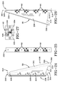
- FIG. 18 is a cross-sectional view similar to FIG. 15 , showing the interconnections between external electrical interface panels and internal electrical interface panels;
- FIG. 19 is a perspective view of the cover of the electrical interface assembly of FIG. 3 ;
- FIG. 20 is a top plan view of the cover of FIG. 19 ;
- FIG. 21 is a front view of the cover of FIG. 19 ;
- FIG. 22 is a side elevational view of the cover of FIG. 19 , showing fully raised and deployed positions in phantom;
- FIG. 23 is a detail view, with a partial cut-away, of a side wing hinge
- FIG. 24 is a perspective view of a side wing of the electrical interface assembly of FIG. 3 ;
- FIG. 25 is an end view of the side wing of FIG. 24 ;
- FIG. 26 is a side elevational view of the side wing of FIG. 24 ;
- FIG. 27 is a detail view of a side wing hinge of FIG. 24 ;
- FIG. 28 is a first side elevational view of a side wing body of FIG. 24 ;
- FIG. 29 is a first end view of the side wing body of FIG. 28 ;
- FIG. 30 is a second side elevational view of the side wing body of FIG. 28 ;
- FIG. 31 is a second end view of the side wing body of FIG. 28 , taken along line 31 - 31 of FIG. 30 ;
- FIG. 32 is a bottom plan view of the side wing body of FIG. 30 ;
- FIG. 33 is a perspective view of a side wing stand-off of FIG. 24 ;
- FIG. 34 is a perspective view of a further side wing of the electrical interface assembly of FIG. 3 ;
- FIG. 35 is a side elevational view, with a partial cut-away, of a further illustrative embodiment electrical interface assembly of the present disclosure
- FIG. 36 is a view similar to FIG. 35 , showing the cover in a deployed position.
- FIG. 37 is a side elevational view, with a partial cut-away thereof, of a further illustrative electrical interface assembly of the present disclosure.
- a mobile structure illustratively a vehicle 10
- vehicle 10 is shown as including a plurality of electrical interface assemblies 11 .
- the vehicle 10 illustratively includes a plurality of ground engaging members 14 which support 44 a frame 16 .
- ground engaging members 14 are shown as comprising tires and wheels, other ground engaging members such as tracks or sleds may be employed.
- the invention is equally applicable to a wide variety of mobile structures (e.g., water floatation devices) as well as fixed structures (e.g., buildings).
- a shelter assembly 18 is supported by the frame 16 and includes a pivotally mounted mast assembly 20 .
- the mast assembly 20 may support various antennae for transmitting and receiving radio frequency signals. Additional details of the mast assembly 20 are provided in U.S. Provisional Patent Application Ser. No. 61/291,694, filed Dec. 31, 2009, entitled “VEHICLE AND MAST MOUNTING ASSEMBLY THEREFOR,” the disclosure of which has been expressly incorporated by reference herein.
- the shelter assembly 18 illustratively includes an enclosure 22 having a top wall 24 , a front wall 26 , side walls 28 and 30 , and a rear wall 32 .
- Shelter assembly 18 may also include a work platform 34 including a hoist 36 , as well as a plurality of antenna 38 positioned around the enclosure 22 .
- a plurality of electrical interface assemblies 11 may be supported within one or more of the walls 26 , 28 , 30 , and 32 of the enclosure 22 .
- an illustrative electrical interface assembly 11 such as a signal interface assembly 12 , is shown removed from the enclosure 22 .
- the signal interface assembly 12 is illustratively configured to provide for simple and efficient electrical communication between an exterior 40 of the enclosure 22 and an interior 42 of the enclosure 22 ( FIG. 3 ). More particularly, the signal interface assembly 12 permits electrical communication between equipment external to the enclosure 22 and equipment received within the enclosure 22 . Such electrical communication may be user defined, and illustratively may include telecommunication signals (e.g. radio frequency signals and data transmissions), electrical power transmissions, etc.
- the signal interface assembly 12 may be positioned within a vertical support structure, such as vertical wall 26 , 28 , 30 , 32 of the enclosure 22 .
- the signal interface assembly 12 illustratively includes a support 44 having a frame 46 coupled to a housing 48 .
- the frame 46 is illustratively formed of a durable material, such as aluminum, and includes an outer support, such as outer frame or mounting bracket 50 , spaced apart from an inner support, such as inner frame or mounting bracket 52 .
- a chamber 54 is defined between the outer frame 50 and the inner frame 52 ( FIGS. 4 , 5 , and 18 ).
- the housing 48 is illustratively coupled to the frame 46 , for example, by welding, and includes a top wall 56 , side walls 58 and 60 , and a bottom wall 62 .
- the housing 48 is illustratively formed of a durable material, such as aluminum.
- one or both of outer frame 50 and the inner frame 52 may be formed integral with the housing 48 .
- the housing 48 illustratively includes an outer end 64 and an inner end 66 , wherein the chamber 54 is positioned intermediate the ends 64 and 66 .
- a mounting flange 68 is coupled to the outer end 64 of the housing 48 and includes a plurality of mounting apertures 70 .
- Fasteners, such as rivets 72 may extend through the apertures 70 for securing the signal interface assembly 12 to the enclosure 22 .
- a first movable member illustratively a cover 76
- a pair of second movable members illustratively side wings 80
- the first hinge 78 permits pivoting movement of the cover 76 about a horizontal axis 84 ( FIG. 3 )
- the second hinges 82 permit pivoting movement of the side wings 80 about respective vertical axes 86 ( FIG. 4 ).
- the cover 76 pivots upwardly from a stowed position to a raised position (including a deployed position), and the side wings 80 pivot outwardly from stowed positions to deployed positions.
- a pair of latching mechanisms 90 are illustratively coupled to the cover 76 and are configured to secure together the cover 76 and respective side wings 80 when positioned in the stowed and deployed configurations.
- the outer frame 50 includes an upper frame member 92 coupled to a lower frame member 94 . Both the upper frame member 92 and the lower frame member 94 are angled relative to each other and to a horizontal axis 96 . As shown in the illustrative embodiment of FIG. 15 , the upper frame member 92 is angled upwardly from the horizontal axis 96 by angle A (illustratively 66 degrees), while the lower frame member 94 is angled downwardly from the horizontal axis 96 by angle B (illustratively 72 degrees).
- a deflector 98 is coupled to the lower frame member 94 and is configured to prevent water from collecting at the bottom of the signal interface assembly 12 .
- the deflector 98 is angled downwardly from a horizontal axis 100 by an angle C (illustratively 23 degrees) for directing water downwardly and outwardly from the signal interface assembly 12 .
- the upper frame member 92 includes first and second openings 102 and 104 defined by rectangular mounting flanges 106 and 108 , respectively. Outer surfaces of the mounting flanges 106 and 108 define respective gasket seats 110 and 112 . A plurality of mounting apertures 114 and 116 extend through each mounting flange 106 and 108 , respectively.
- the lower frame member 94 includes first and second openings 122 and 124 defined by rectangular mounting flanges 126 and 128 , respectively. Outer surfaces of mounting flanges 126 and 128 define respective gasket seats 130 and 132 . A plurality of mounting apertures 134 and 136 extend through each mounting flange 126 and 128 , respectively.
- a plurality of outer or external electrical interface panels illustratively signal entry panels 140 , 142 , and 144 , are removably coupled to the outer frame 50 by a plurality of releasable couplers or fasteners, illustratively bolts 146 received within the mounting apertures 114 , 116 , 134 , 136 of the respective frame members 92 and 94 .
- An electromagnetic interference (EMI) gasket 148 is received intermediate each signal entry panel 140 , 142 , 144 and its respective gasket seat 110 , 112 , 130 , 132 .
- the EMI gasket 148 is illustratively formed of an electrically conductive material, such as wire mesh material.
- the EMI gasket 148 comprises a carbon-filled cellular PTFE matrix 150 .
- a pressure sensitive adhesive (PSA) 152 may be supported by a rear surface of the matrix 150 .
- Each outer signal entry panel 140 , 142 and 144 may be customized with a variety of different electrical connectors or ports as desired by the user for providing electrical communication with components external to the shelter assembly 18 .
- the outer signal entry panels 140 , 142 , 144 are modular and may be easily removed and replaced with other electrical interface panels. While illustrative outer signal entry panels 140 , 142 , and 144 are shown to include certain types, arrangements, and numbers of electrical connectors, it should be appreciated that a wide variety of substitutions may be made therefor.
- outer signal entry panel 140 each include a telephone HAUC connector 154 .
- HAUC connectors 154 are known and include a housing 156 supporting a receptacle for mating with a telephone, illustratively a handset including a microphone and a speaker (not shown).
- a cap 158 is removably coupled to the housing 156 , while a cable 160 retains the cap 158 to the housing 156 ( FIG. 12 ).
- the signal entry panel 142 illustratively includes a plurality of telephone push pins 162 , and data ports 164 and 166 .
- Data ports 164 illustratively comprise Tactical Digital Information Link (TADIL) connectors, such as TADIL-J 1553 bayonet couplings.
- Data ports 166 illustratively comprise female cable connectors, such as category 5 (CAT-5e) cable connectors.
- the outer signal entry panel 144 illustratively includes a plurality of data ports 168 for coupling to fiber optic cables.
- the data ports 168 comprise Tactical Fiber Optic Cable Assembly (TFOCA-11) connectors including a housing 170 and threadably coupled protective caps 172 .
- the inner frame 52 illustratively includes an upper frame member 174 and a lower frame member 176 disposed within a common substantially vertical plane.
- the upper frame member 174 includes first and second openings 180 and 182 defined by rectangular mounting flanges 184 and 186 , respectively. Outer surfaces of the mounting flanges 184 and 186 define respective gasket seats 188 and 190 .
- a plurality of mounting apertures 192 and 194 extend through each mounting flange 184 and 186 , respectively.
- the lower frame member 176 includes first and second openings 198 and 200 defined by rectangular mounting flanges 202 and 204 , respectively. Outer surfaces of the mounting flanges 202 and 204 define respective gasket seats 206 and 208 .
- a plurality of mounting apertures 210 and 212 extend through each mounting flange 202 and 204 , respectively.
- a plurality of inner or internal electrical interface panels illustratively signal entry panels 214 , 216 , and 218 , are removably coupled to the inner frame 52 by a plurality of releasable couplers or fasteners, illustratively bolts 220 received within the mounting apertures 192 , 194 , 210 , 212 of respective frame members 174 and 176 .
- An EMI gasket 222 is received intermediate each signal entry panel 214 , 216 , 218 and its respective gasket seat 188 , 190 , 206 , 208 .
- the EMI gaskets 222 are illustratively of a similar construction as EMI gaskets 148 detailed above.
- Each inner signal entry panel 214 , 216 , 218 may be customized with a variety of different electrical connectors or ports as desired by the user for providing electrical communication with components internal to the shelter assembly 18 .
- the panels 214 , 216 , 218 are modular and may be easily removed and replaced with other electrical interface panels as desired. While illustrative inner signal entry panels 214 , 216 , and 218 are shown to include certain types, arrangements, and numbers of electrical connectors, it should be appreciated that a wide variety of substitutions may be made therefor.
- inner signal entry panels 214 each include a plurality of telephone connectors, illustratively RJ-45 modular connectors 224 .
- the signal entry panel 216 illustratively includes a plurality of telephone push pins 226 and data ports 228 and 230 .
- Data ports 228 illustratively comprise TADIL connectors, such as TADIL-J 1553 bayonet couplings.
- Data ports 230 illustratively comprise female cable connectors, such as category 5 (CAT-5e) cable connectors.
- the signal entry panel 218 illustratively includes fiber optic couplings 232 , such as SC MMSM connectors.
- a ground stud 234 may also be supported by the inner frame 52 .
- Electrical wires or cables 236 , 238 , 240 , 242 illustratively connect the outer signal entry panels 140 , 142 , 144 with the inner signal entry panels 214 , 216 , 218 , respectively. More particularly, the cables 236 , 238 , 240 , 242 extend between the outer frame 50 and the inner frame 52 through the chamber 54 of the support 44 as shown in FIG. 18 .
- the HAUC connectors 154 of outer signal entry panel 140 are illustratively coupled to the modular connectors 224 of panel 214 by cables 236 .
- the push pins 162 of the outer signal entry panel 142 are illustratively coupled to the push pins 226 of the inner signal entry panel 216 by cables 238 .
- the data ports 164 and 166 of the outer signal entry panel 142 are coupled to the data ports 228 and 230 of panel 216 by cables 240 and 242 , respectively.
- the ports 168 of the outer signal entry panel 144 are illustratively coupled to the couplings 232 of the internal signal entry panel 218 through cables (not shown).
- lighting arrestors and filters may be electrically coupled to the cables 236 , 238 , 240 , 242 and received within the chamber 54 .
- the cover 76 is pivotably coupled to the top wall 56 of the housing 48 by a first hinge 78 .
- the cover 76 illustratively includes a substantially planar body 244 having an outer surface 245 extending between first and second sides 246 and 247 and between opposing upper and lower ends 248 and 249 . While the body 244 of the cover 76 may be formed in a wide variety of sizes, the illustrative embodiment has a width cw of approximately 13 inches, and a height ch of approximately 20 inches ( FIG. 21 ). In one illustrative embodiment, the cover 76 is formed of 0.090 inch thick aluminum sheet.
- the first hinge 78 is coupled to the body 244 proximate the upper end 248 , while the latching mechanisms 90 are secured to the body 244 proximate the lower end 249 near opposing sides 246 and 247 .
- a peripheral lip or flange 250 extends inwardly from the body 244 by a distance cf (illustratively about 0.50 inches).
- the first hinge 78 illustratively includes a plurality of spaced apart connecting members 252 .
- Each connecting member 252 illustratively includes a detent assembly 254 to releasably secure the cover 76 in one of a plurality of angular positions. More particularly, the cover 76 in FIG. 22 is shown in solid in a stowed position substantially vertical (i.e., parallel with the vertical wall 26 ). The cover 76 may be pivoted upwardly by angle ⁇ (illustratively about 90 degrees) to a fully raised position, and by angle ⁇ (illustratively about 45 degrees) to an intermediate deployed position.
- each connecting member 252 illustratively includes a first pivot body 256 and a second pivot body 258 operably coupled together for pivoting movement by a pivot pin 260 .
- Torsion springs 261 may be provided to angularly bias the second pivot body 258 away from the first pivot body 256 . As such, the springs 261 assist the user in raising the cover 76 .
- each connecting member 252 illustratively includes a first member 262 having a head 264 at a first end, and a cavity 266 at an opposing second end.
- a second member 268 is concentrically received within the cavity 266 of the first member 262 . More particularly, a portion 270 adjacent the first end of the second member 268 is fixed within the cavity 266 , and a head 272 is positioned adjacent the second end.
- the first and second members 262 and 268 are secured together such that the first and second pivot bodies 256 and 258 are captured between the heads 264 and 272 .
- the detent assembly 254 illustratively includes spaced apart first and second sliders 273 and 274 configured to cooperate with recesses or detents 276 and 278 , respectively, formed within the pivot body 256 . More particularly, each slider 273 , 274 is configured to be releasably received within a cooperating detent 276 , 278 in each of the angular positions shown in FIG. 22 .
- the sliders 273 and 274 illustratively comprise sleeves received over the pivot pin 260 and supported for sliding movement along the longitudinal axis 280 of the pin 260 .
- a spring 282 is configured to bias the sliders 273 and 274 in opposite directions along the longitudinal axis 280 and into selected ones of the detents 276 and 278 .
- the cover 76 is releasably secured within one of the angular positions shown in FIG. 22 .
- a protective flap or shield 284 may extend over the first hinge 78 to prevent environmental elements (e.g., rain, sand and dirt) from passing through gaps in the hinge 78 and to the outer signal entry panel 140 , 142 and 144 .
- the protective shield 284 illustratively comprises a flexible sheet having a first or upper end 286 secured to the first hinge 78 by fasteners, such as screws, and a second or lower end 288 free to move relative to the cover 76 .
- the protective shield 284 is formed of a durable and flexible material, such as an elastomeric sheet.
- each side wing 80 is pivotably coupled by a plurality of second hinges 82 to a spacer or standoff 290 .
- each standoff 290 is secured to a side wall 58 , 60 of the housing 48 ( FIG. 5 ).
- Each standoff 290 may be formed of an elastomeric body 292 secured to the side wall 58 , 60 by a plurality of fasteners, such as screws 294 .
- the standoffs 290 provide clearance from the sidewalls 58 and 60 to accommodate pivoting movement of the side wings 80 .
- Each side wing 80 illustratively includes a substantially planar body 296 extending between a first side 298 and a second side 300 . While the body 296 of each side wing 80 may be formed from a wide variety of rigid, durable materials, in the illustrative embodiment the body 296 is formed of 0.125 inch thick aluminum sheet.
- the first side 298 includes a substantially vertical edge 302
- the second side 300 illustratively includes an angled edge 304 .
- the second side 300 illustratively includes an inwardly extending lip or flange 306 . As shown in the illustrative embodiment of FIG. 31 , the flange 306 extends inwardly from the body 296 by a distance sf (illustratively about 0.88 inches).
- each side wing 80 has a substantially triangular shape with an apex 308 at an upper end 310 and a base 312 at a lower end 314 .
- the vertical edge 302 is illustratively angled relative to the angled edge 304 by approximately 17 degrees.
- the second hinges 82 are coupled to the body 296 proximate the first side 298 and provide for pivoting movement of the wings 80 from the stowed position of FIGS. 8 and 9 to the deployed position of FIGS. 6 and 10 .
- the base 312 includes a cut-out or notch 316 defining opposing first and second sections of the body 296 , illustratively first and second tabs 318 and 320 .
- the notch 316 is configured to provide clearance for a portion of the latching mechanism 90 when the cover 76 and the side wings 80 are in their stowed positions.
- the base 312 of the body 296 illustratively has a width sw of approximately 5.4 inches ( FIG. 28 ), while the vertical edge 302 illustratively has a height sh of approximately 16 inches ( FIG. 30 ).
- the angled edge 304 illustratively has a length sl of approximately 16.02 inches ( FIG. 31 ). Additional illustrative dimensions of the tabs 318 and 320 defining the notch 316 are shown in FIG. 30 .
- each of the plurality of second hinges 82 illustratively includes a first pivot body 322 operably coupled to a second pivot body 324 by a pivot pin 326 to provide pivoting movement therebetween.
- the first pivot body 322 is secured to the standoff 290 while the second pivot body 324 is secured to the respective side wing 80 .
- a torsion spring 328 is configured to angularly bias about the pivot pin 326 the second pivot body 324 away from the first pivot body 322 . As such, the torsion spring 328 biases the respective side wings 80 outwardly about vertical axis 86 ( FIG. 26 ) from the stowed position ( FIG. 4 ) to the deployed position ( FIG. 6 ).
- the latching mechanisms 90 are configured to secure together the cover 76 and the side wings 80 in a plurality of configurations. More particularly, in the illustrative embodiment, the latching mechanisms 90 are configured to secure together the cover 76 and the side wings 80 in relative positions in either of their respective stowed or deployed configurations.
- FIGS. 8 and 9 show locked and unlocked positions (in solid and hidden lines, respectively) of latching mechanism 90 when the cover 76 and side wings 80 are in their stowed configurations.
- the cover 76 and the side wings 80 extend substantially parallel to each other and to the vertical wall 26 to define a substantially flush outer surface 323 ( FIG. 1 ).
- the first side 298 of each side wing 80 is positioned adjacent the flange 250 at respective sides 246 and 247 of the cover 76 .
- the latching mechanisms 90 secure the first tabs 318 of each side wing 80 to the cover 76 .
- the standoff 290 may serve as a buffer or stop to contact the flange 250 at respective sides 246 and 247 of the cover 76 .
- FIGS. 6 and 10 show locked and unlocked positions (in solid and hidden lines, respectively) of the cover 76 and the side wings 80 are in their deployed configurations.
- the cover 76 is angled upwardly from its vertical position by angle ⁇ of about 45 degrees from its position of FIG. 8 .
- the side wings 80 are angled outwardly from their folded positions of FIG. 8 by about 90 degrees.
- the second side 300 of each side wing 80 is positioned adjacent the flange 250 at the respective sides 246 and 247 of the cover 76 .
- the latching mechanisms 90 secure the flange 250 at the second side tabs 320 of each side wing 80 to the cover 76 .
- each latching mechanism 90 illustratively includes a handle 325 received within a recess 327 formed in the outer surface 245 of the cover 76 .
- a lever arm 329 is coupled to the handle 325 and is configured to pivot about a pivot pin 330 .
- An adjustable clamp 332 is supported at a first end of the lever arm 329 , while the handle 325 is coupled to the second end of the lever arm 329 .
- the clamp 332 includes a threaded stud 334 cooperating with a nut 336 for adjusting the position of a resilient bearing member 338 .
- the latching mechanism 90 defines an over-center clamp by the handle 325 and the lever arm 329 being positioned on opposite sides of the pivot pin 330 .
- the latching mechanism 90 is in a locked or clamped position when the handle 325 is substantially parallel to the outer surface 245 of the cover 76 (shown in solid lines in FIGS. 9 and 10 ).
- FIG. 9 shows the stowed configuration where the clamp 332 in the lock position secures the first tab 318 of the side wing 80 to the body 244 of the cover 76 .
- FIG. 10 shows the deployed configuration where the clamp 332 in the locked position secures the second tab 320 of the side wing 80 to the body 244 of the cover 76 .
- the handle 325 may be lifted or pulled outwardly away from the cover 76 such that the handle 325 and the lever arm 329 are pivoted about pivot pin 330 (to the position shown in hidden lines in FIGS. 9 and 10 ).
- the handle 325 may be pushed back into the recess 327 and flush with the outer surface 245 of the cover 76 .
- the lever arm 329 rotates such that the clamp 332 secures the cover 76 to the respective side wing 80 .
- An illustrative method of accessing an interface panel of signal interface assembly 12 comprises the steps of releasing the latching mechanisms 90 securing cover 76 to the side wings 80 ( FIGS. 8 and 9 ) when in the stowed configuration.
- the cover 76 In the stowed configuration, the cover 76 extends substantially parallel to the side wings 80 to provide a flush outer surface to the support 44 .
- the handles 325 are pivoted outwardly from the recesses 327 of cover 76 .
- the lever arms 329 unclamp the cover 76 from the first tabs 318 of the side wings 80 .
- the cover 76 is pivoted upwardly about horizontal axis 100 , illustratively by angle ⁇ to the fully raised position shown in FIG. 22 .
- the detent assemblies 254 are configured to releasably hold the cover 76 in this position.
- the side wings are 80 are then pivoted outwardly about vertical axis 86 into the deployed position shown in FIG. 6 .
- the step of pivoting the side wings 80 outwardly includes biasing the side wings 80 through a spring 282 .
- the cover 76 is then lowered (pulling down will release the detent assemblies 254 ) to the deployed position represented by angle ⁇ in FIG. 22 .
- the cover 76 extends substantially perpendicular to the side wings 80 and at an acute angle relative to vertical.
- the flange 250 of the cover 76 receives the second tab 320 of each side wing 80 in a nesting arrangement.
- the latching mechanisms 90 are engaged to secure the cover 76 to the side wings 80 . More particularly, the handles 325 are pivoted inwardly into the recesses 327 of the cover 76 . In response, the lever arms 329 clamp the cover 76 to the second tab 320 of the side wings 80 .
- a method of installing a signal entry panel comprises the steps of providing support 44 , and coupling signal entry panel 140 , 142 , 144 , 214 , 216 , 218 to the support 44 .
- the support 44 illustratively includes outer frame 50 and inner frame 52 .
- EMI gasket 148 is positioned adjacent the outer frame 50
- the outer signal entry panel 140 , 142 , 144 is positioned adjacent the outer frame 50 with the EMI gasket 148 being intermediate the panel 140 , 142 , 144 , and the outer frame 50 .
- Bolts 146 are threadably secured within the outer frame 50 to retain the outer signal entry panel 140 , 142 , 144 in position.
- Cables are illustratively used to electrically couple the outer signal entry panel 140 , 142 , 144 , to the respective inner signal entry panel 214 , 216 , 218 .
- EMI gasket 222 is positioned against inner frame 52 and the inner signal entry panel 214 , 216 , 218 is then retained in position through bolts 220 threadably secured within the inner frame 52 .
- the mounting arrangements of the outer and inner signal entry panels 140 , 142 , 144 , 214 , 216 , 218 facilitate replacement by substitute panels.
- bolts 146 , 220 permit removal and replacement of signal entry panels 140 , 142 , 144 , 214 , 216 , 218 on the outer frame 50 and the inner frame 52 , respectively.
- the cover 76 and side wings 80 may be operated as detailed herein to protect the outer signal entry panels 140 , 142 , 144 from environmental elements.
- the signal interface assembly 412 includes many similar features to the embodiments detailed above. As such, similar elements will be identified with like reference numbers.
- the signal interface assembly 412 illustratively includes flexible side shields 414 configured to extend adjacent, and in laterally spaced relation to, the side wings 80 .
- the flexible side shields 414 may replace the side wings 80 .
- the side shields 414 further assist in preventing environmental elements, such as water, sand, and debris, from contacting the signal entry panels 214 .
- the side shields 414 may each comprise an inflatable bladder 416 fluidly coupled to a fluid supply 418 , such as a pneumatic pump or storage cannister, through a fluid supply line 420 .
- a first end of the bladder 416 illustratively includes a mounting strip 422 secured to the housing, while a second end of the bladder 416 illustratively includes a magnetic coupler 424 for releasable coupling to an inner surface of the cover 76 .
- FIG. 35 shows the bladder 416 in a deflated state and disconnected from the cover 76
- FIG. 36 shows the bladder 416 inflated and coupled to the cover 76
- the fluid supply 418 may be activated for inflating the bladder 416 through a user interface, such as a user controlled switch, or through a sensor, such as a limit switch 426 configured to detect when the cover 76 is raised.
- FIG. 37 shows a further illustrative signal interface assembly 512 having many similar features to the embodiments detailed above. As such, similar elements will be identified with like reference numbers.
- the signal interface assembly 512 includes flexible side shields 514 configured to extend adjacent, and in laterally spaced relation to, the side wings 80 .
- the flexible side shields 514 may replace the side wings 80 .
- the side shields 514 may each comprise a flexible curtain 516 having a first end secured to the housing 48 , and a second end coupled to the cover 76 .
- Each curtain 516 illustratively includes a plurality of foldable panels 518 supported between braces 520 .
- the panels 518 are configured to collapse or fold in an accordion fashion.
- a releasable coupler such as a hook and look fastener 522 , illustratively secures the second end of the flexible curtain 516 to the cover 76 . More particularly, a hook portion 524 may be secured to the cover 76 , and a mating loop portion 526 may be secured to the curtain 516 .
- a retractor 528 is illustratively configured to fold the curtain 516 .
- Retractor 528 may include a cord 530 supported on a rotatable spool 532 . As the cord 530 is wound onto the spool 532 , the second end of the curtain 516 is retracted and the curtain 516 folds or retracts inwardly.
- a drive mechanism (not shown) may be operably coupled to the spool 532 for imparting rotation thereof.
Abstract
Description
Claims (21)
Priority Applications (1)
| Application Number | Priority Date | Filing Date | Title |
|---|---|---|---|
| US13/864,583 US8802983B2 (en) | 2009-12-31 | 2013-04-17 | Protective members for an electrical interface assembly |
Applications Claiming Priority (3)
| Application Number | Priority Date | Filing Date | Title |
|---|---|---|---|
| US29169409P | 2009-12-31 | 2009-12-31 | |
| US12/696,778 US8450609B2 (en) | 2009-12-31 | 2010-01-29 | Protective members for an electrical interface assembly |
| US13/864,583 US8802983B2 (en) | 2009-12-31 | 2013-04-17 | Protective members for an electrical interface assembly |
Related Parent Applications (1)
| Application Number | Title | Priority Date | Filing Date |
|---|---|---|---|
| US12/696,778 Division US8450609B2 (en) | 2009-12-31 | 2010-01-29 | Protective members for an electrical interface assembly |
Publications (2)
| Publication Number | Publication Date |
|---|---|
| US20130235533A1 US20130235533A1 (en) | 2013-09-12 |
| US8802983B2 true US8802983B2 (en) | 2014-08-12 |
Family
ID=44185776
Family Applications (7)
| Application Number | Title | Priority Date | Filing Date |
|---|---|---|---|
| US12/696,861 Active 2032-04-09 US8789261B2 (en) | 2009-12-31 | 2010-01-29 | Communications vehicle |
| US12/696,856 Active 2031-01-19 US8276325B2 (en) | 2009-12-31 | 2010-01-29 | Vehicle and mast mounting assembly therefor |
| US12/696,778 Expired - Fee Related US8450609B2 (en) | 2009-12-31 | 2010-01-29 | Protective members for an electrical interface assembly |
| US12/696,787 Expired - Fee Related US8283562B2 (en) | 2009-12-31 | 2010-01-29 | Electrical interface assembly |
| US13/623,561 Expired - Fee Related US8904736B2 (en) | 2009-12-31 | 2012-09-20 | Vehicle and mast mounting assembly therefor |
| US13/626,245 Active US8576548B2 (en) | 2009-12-31 | 2012-09-25 | Communications vehicle |
| US13/864,583 Expired - Fee Related US8802983B2 (en) | 2009-12-31 | 2013-04-17 | Protective members for an electrical interface assembly |
Family Applications Before (6)
| Application Number | Title | Priority Date | Filing Date |
|---|---|---|---|
| US12/696,861 Active 2032-04-09 US8789261B2 (en) | 2009-12-31 | 2010-01-29 | Communications vehicle |
| US12/696,856 Active 2031-01-19 US8276325B2 (en) | 2009-12-31 | 2010-01-29 | Vehicle and mast mounting assembly therefor |
| US12/696,778 Expired - Fee Related US8450609B2 (en) | 2009-12-31 | 2010-01-29 | Protective members for an electrical interface assembly |
| US12/696,787 Expired - Fee Related US8283562B2 (en) | 2009-12-31 | 2010-01-29 | Electrical interface assembly |
| US13/623,561 Expired - Fee Related US8904736B2 (en) | 2009-12-31 | 2012-09-20 | Vehicle and mast mounting assembly therefor |
| US13/626,245 Active US8576548B2 (en) | 2009-12-31 | 2012-09-25 | Communications vehicle |
Country Status (1)
| Country | Link |
|---|---|
| US (7) | US8789261B2 (en) |
Families Citing this family (175)
| Publication number | Priority date | Publication date | Assignee | Title |
|---|---|---|---|---|
| CN102474084A (en) | 2009-08-06 | 2012-05-23 | 3M创新有限公司 | System and method for providing final drop in a living unit in a building |
| US8789261B2 (en) * | 2009-12-31 | 2014-07-29 | The United States Of America As Represented By The Secretary Of The Navy | Communications vehicle |
| JP2012243980A (en) * | 2011-05-20 | 2012-12-10 | Canon Inc | Casing for electronic apparatus and image formation apparatus |
| US8804374B2 (en) * | 2011-10-12 | 2014-08-12 | International Business Machines Corporation | Electromagnetic interference shield |
| US9020321B2 (en) * | 2012-04-10 | 2015-04-28 | Tyco Electronics Corporation | Wall outlet having enclosed service connection |
| US10312715B2 (en) | 2015-09-16 | 2019-06-04 | Energous Corporation | Systems and methods for wireless power charging |
| US10263432B1 (en) | 2013-06-25 | 2019-04-16 | Energous Corporation | Multi-mode transmitter with an antenna array for delivering wireless power and providing Wi-Fi access |
| US9899873B2 (en) | 2014-05-23 | 2018-02-20 | Energous Corporation | System and method for generating a power receiver identifier in a wireless power network |
| US10205239B1 (en) | 2014-05-07 | 2019-02-12 | Energous Corporation | Compact PIFA antenna |
| US10243414B1 (en) | 2014-05-07 | 2019-03-26 | Energous Corporation | Wearable device with wireless power and payload receiver |
| US10218227B2 (en) | 2014-05-07 | 2019-02-26 | Energous Corporation | Compact PIFA antenna |
| US10211674B1 (en) | 2013-06-12 | 2019-02-19 | Energous Corporation | Wireless charging using selected reflectors |
| US9124125B2 (en) | 2013-05-10 | 2015-09-01 | Energous Corporation | Wireless power transmission with selective range |
| US9893555B1 (en) | 2013-10-10 | 2018-02-13 | Energous Corporation | Wireless charging of tools using a toolbox transmitter |
| US9876379B1 (en) | 2013-07-11 | 2018-01-23 | Energous Corporation | Wireless charging and powering of electronic devices in a vehicle |
| US9806564B2 (en) | 2014-05-07 | 2017-10-31 | Energous Corporation | Integrated rectifier and boost converter for wireless power transmission |
| US10965164B2 (en) | 2012-07-06 | 2021-03-30 | Energous Corporation | Systems and methods of wirelessly delivering power to a receiver device |
| US9906065B2 (en) | 2012-07-06 | 2018-02-27 | Energous Corporation | Systems and methods of transmitting power transmission waves based on signals received at first and second subsets of a transmitter's antenna array |
| US10256657B2 (en) | 2015-12-24 | 2019-04-09 | Energous Corporation | Antenna having coaxial structure for near field wireless power charging |
| US10291055B1 (en) | 2014-12-29 | 2019-05-14 | Energous Corporation | Systems and methods for controlling far-field wireless power transmission based on battery power levels of a receiving device |
| US9825674B1 (en) | 2014-05-23 | 2017-11-21 | Energous Corporation | Enhanced transmitter that selects configurations of antenna elements for performing wireless power transmission and receiving functions |
| US9831718B2 (en) | 2013-07-25 | 2017-11-28 | Energous Corporation | TV with integrated wireless power transmitter |
| US10186913B2 (en) | 2012-07-06 | 2019-01-22 | Energous Corporation | System and methods for pocket-forming based on constructive and destructive interferences to power one or more wireless power receivers using a wireless power transmitter including a plurality of antennas |
| US9893768B2 (en) | 2012-07-06 | 2018-02-13 | Energous Corporation | Methodology for multiple pocket-forming |
| US10063105B2 (en) | 2013-07-11 | 2018-08-28 | Energous Corporation | Proximity transmitters for wireless power charging systems |
| US9939864B1 (en) | 2014-08-21 | 2018-04-10 | Energous Corporation | System and method to control a wireless power transmission system by configuration of wireless power transmission control parameters |
| US10223717B1 (en) | 2014-05-23 | 2019-03-05 | Energous Corporation | Systems and methods for payment-based authorization of wireless power transmission service |
| US9843201B1 (en) | 2012-07-06 | 2017-12-12 | Energous Corporation | Wireless power transmitter that selects antenna sets for transmitting wireless power to a receiver based on location of the receiver, and methods of use thereof |
| US10211682B2 (en) | 2014-05-07 | 2019-02-19 | Energous Corporation | Systems and methods for controlling operation of a transmitter of a wireless power network based on user instructions received from an authenticated computing device powered or charged by a receiver of the wireless power network |
| US10224758B2 (en) | 2013-05-10 | 2019-03-05 | Energous Corporation | Wireless powering of electronic devices with selective delivery range |
| US9973021B2 (en) | 2012-07-06 | 2018-05-15 | Energous Corporation | Receivers for wireless power transmission |
| US10230266B1 (en) | 2014-02-06 | 2019-03-12 | Energous Corporation | Wireless power receivers that communicate status data indicating wireless power transmission effectiveness with a transmitter using a built-in communications component of a mobile device, and methods of use thereof |
| US10199835B2 (en) | 2015-12-29 | 2019-02-05 | Energous Corporation | Radar motion detection using stepped frequency in wireless power transmission system |
| US10193396B1 (en) | 2014-05-07 | 2019-01-29 | Energous Corporation | Cluster management of transmitters in a wireless power transmission system |
| US9876648B2 (en) | 2014-08-21 | 2018-01-23 | Energous Corporation | System and method to control a wireless power transmission system by configuration of wireless power transmission control parameters |
| US9847679B2 (en) | 2014-05-07 | 2017-12-19 | Energous Corporation | System and method for controlling communication between wireless power transmitter managers |
| US10291066B1 (en) | 2014-05-07 | 2019-05-14 | Energous Corporation | Power transmission control systems and methods |
| US10008889B2 (en) | 2014-08-21 | 2018-06-26 | Energous Corporation | Method for automatically testing the operational status of a wireless power receiver in a wireless power transmission system |
| US9899861B1 (en) | 2013-10-10 | 2018-02-20 | Energous Corporation | Wireless charging methods and systems for game controllers, based on pocket-forming |
| US9859756B2 (en) | 2012-07-06 | 2018-01-02 | Energous Corporation | Transmittersand methods for adjusting wireless power transmission based on information from receivers |
| US9991741B1 (en) | 2014-07-14 | 2018-06-05 | Energous Corporation | System for tracking and reporting status and usage information in a wireless power management system |
| US10124754B1 (en) | 2013-07-19 | 2018-11-13 | Energous Corporation | Wireless charging and powering of electronic sensors in a vehicle |
| US9876394B1 (en) | 2014-05-07 | 2018-01-23 | Energous Corporation | Boost-charger-boost system for enhanced power delivery |
| US11502551B2 (en) | 2012-07-06 | 2022-11-15 | Energous Corporation | Wirelessly charging multiple wireless-power receivers using different subsets of an antenna array to focus energy at different locations |
| US10038337B1 (en) * | 2013-09-16 | 2018-07-31 | Energous Corporation | Wireless power supply for rescue devices |
| US9787103B1 (en) | 2013-08-06 | 2017-10-10 | Energous Corporation | Systems and methods for wirelessly delivering power to electronic devices that are unable to communicate with a transmitter |
| US9859797B1 (en) | 2014-05-07 | 2018-01-02 | Energous Corporation | Synchronous rectifier design for wireless power receiver |
| US10992185B2 (en) | 2012-07-06 | 2021-04-27 | Energous Corporation | Systems and methods of using electromagnetic waves to wirelessly deliver power to game controllers |
| US20140008993A1 (en) | 2012-07-06 | 2014-01-09 | DvineWave Inc. | Methodology for pocket-forming |
| US9882427B2 (en) | 2013-05-10 | 2018-01-30 | Energous Corporation | Wireless power delivery using a base station to control operations of a plurality of wireless power transmitters |
| US9948135B2 (en) | 2015-09-22 | 2018-04-17 | Energous Corporation | Systems and methods for identifying sensitive objects in a wireless charging transmission field |
| US9867062B1 (en) | 2014-07-21 | 2018-01-09 | Energous Corporation | System and methods for using a remote server to authorize a receiving device that has requested wireless power and to determine whether another receiving device should request wireless power in a wireless power transmission system |
| US10206185B2 (en) | 2013-05-10 | 2019-02-12 | Energous Corporation | System and methods for wireless power transmission to an electronic device in accordance with user-defined restrictions |
| US10128699B2 (en) | 2014-07-14 | 2018-11-13 | Energous Corporation | Systems and methods of providing wireless power using receiver device sensor inputs |
| US9843213B2 (en) | 2013-08-06 | 2017-12-12 | Energous Corporation | Social power sharing for mobile devices based on pocket-forming |
| US10090886B1 (en) | 2014-07-14 | 2018-10-02 | Energous Corporation | System and method for enabling automatic charging schedules in a wireless power network to one or more devices |
| US9252628B2 (en) | 2013-05-10 | 2016-02-02 | Energous Corporation | Laptop computer as a transmitter for wireless charging |
| US10050462B1 (en) | 2013-08-06 | 2018-08-14 | Energous Corporation | Social power sharing for mobile devices based on pocket-forming |
| US10128693B2 (en) | 2014-07-14 | 2018-11-13 | Energous Corporation | System and method for providing health safety in a wireless power transmission system |
| US9871398B1 (en) | 2013-07-01 | 2018-01-16 | Energous Corporation | Hybrid charging method for wireless power transmission based on pocket-forming |
| US9954374B1 (en) | 2014-05-23 | 2018-04-24 | Energous Corporation | System and method for self-system analysis for detecting a fault in a wireless power transmission Network |
| US9812890B1 (en) | 2013-07-11 | 2017-11-07 | Energous Corporation | Portable wireless charging pad |
| US9847677B1 (en) | 2013-10-10 | 2017-12-19 | Energous Corporation | Wireless charging and powering of healthcare gadgets and sensors |
| US9438045B1 (en) | 2013-05-10 | 2016-09-06 | Energous Corporation | Methods and systems for maximum power point transfer in receivers |
| US9887739B2 (en) | 2012-07-06 | 2018-02-06 | Energous Corporation | Systems and methods for wireless power transmission by comparing voltage levels associated with power waves transmitted by antennas of a plurality of antennas of a transmitter to determine appropriate phase adjustments for the power waves |
| US10992187B2 (en) | 2012-07-06 | 2021-04-27 | Energous Corporation | System and methods of using electromagnetic waves to wirelessly deliver power to electronic devices |
| US10090699B1 (en) | 2013-11-01 | 2018-10-02 | Energous Corporation | Wireless powered house |
| US9893554B2 (en) | 2014-07-14 | 2018-02-13 | Energous Corporation | System and method for providing health safety in a wireless power transmission system |
| US9838083B2 (en) | 2014-07-21 | 2017-12-05 | Energous Corporation | Systems and methods for communication with remote management systems |
| US10211680B2 (en) | 2013-07-19 | 2019-02-19 | Energous Corporation | Method for 3 dimensional pocket-forming |
| US10063064B1 (en) | 2014-05-23 | 2018-08-28 | Energous Corporation | System and method for generating a power receiver identifier in a wireless power network |
| US10141791B2 (en) | 2014-05-07 | 2018-11-27 | Energous Corporation | Systems and methods for controlling communications during wireless transmission of power using application programming interfaces |
| US20150326070A1 (en) | 2014-05-07 | 2015-11-12 | Energous Corporation | Methods and Systems for Maximum Power Point Transfer in Receivers |
| US10063106B2 (en) | 2014-05-23 | 2018-08-28 | Energous Corporation | System and method for a self-system analysis in a wireless power transmission network |
| US9923386B1 (en) | 2012-07-06 | 2018-03-20 | Energous Corporation | Systems and methods for wireless power transmission by modifying a number of antenna elements used to transmit power waves to a receiver |
| US10103582B2 (en) | 2012-07-06 | 2018-10-16 | Energous Corporation | Transmitters for wireless power transmission |
| US9912199B2 (en) | 2012-07-06 | 2018-03-06 | Energous Corporation | Receivers for wireless power transmission |
| US10439448B2 (en) | 2014-08-21 | 2019-10-08 | Energous Corporation | Systems and methods for automatically testing the communication between wireless power transmitter and wireless power receiver |
| US9966765B1 (en) | 2013-06-25 | 2018-05-08 | Energous Corporation | Multi-mode transmitter |
| US10148097B1 (en) | 2013-11-08 | 2018-12-04 | Energous Corporation | Systems and methods for using a predetermined number of communication channels of a wireless power transmitter to communicate with different wireless power receivers |
| US10381880B2 (en) | 2014-07-21 | 2019-08-13 | Energous Corporation | Integrated antenna structure arrays for wireless power transmission |
| US10224982B1 (en) | 2013-07-11 | 2019-03-05 | Energous Corporation | Wireless power transmitters for transmitting wireless power and tracking whether wireless power receivers are within authorized locations |
| US10199849B1 (en) | 2014-08-21 | 2019-02-05 | Energous Corporation | Method for automatically testing the operational status of a wireless power receiver in a wireless power transmission system |
| US10270261B2 (en) | 2015-09-16 | 2019-04-23 | Energous Corporation | Systems and methods of object detection in wireless power charging systems |
| US10141768B2 (en) | 2013-06-03 | 2018-11-27 | Energous Corporation | Systems and methods for maximizing wireless power transfer efficiency by instructing a user to change a receiver device's position |
| US9941754B2 (en) | 2012-07-06 | 2018-04-10 | Energous Corporation | Wireless power transmission with selective range |
| US9853458B1 (en) | 2014-05-07 | 2017-12-26 | Energous Corporation | Systems and methods for device and power receiver pairing |
| US9538382B2 (en) | 2013-05-10 | 2017-01-03 | Energous Corporation | System and method for smart registration of wireless power receivers in a wireless power network |
| US9537357B2 (en) | 2013-05-10 | 2017-01-03 | Energous Corporation | Wireless sound charging methods and systems for game controllers, based on pocket-forming |
| US10103552B1 (en) | 2013-06-03 | 2018-10-16 | Energous Corporation | Protocols for authenticated wireless power transmission |
| US10021523B2 (en) | 2013-07-11 | 2018-07-10 | Energous Corporation | Proximity transmitters for wireless power charging systems |
| US9979440B1 (en) | 2013-07-25 | 2018-05-22 | Energous Corporation | Antenna tile arrangements configured to operate as one functional unit |
| US10075017B2 (en) | 2014-02-06 | 2018-09-11 | Energous Corporation | External or internal wireless power receiver with spaced-apart antenna elements for charging or powering mobile devices using wirelessly delivered power |
| US9935482B1 (en) | 2014-02-06 | 2018-04-03 | Energous Corporation | Wireless power transmitters that transmit at determined times based on power availability and consumption at a receiving mobile device |
| US9966784B2 (en) | 2014-06-03 | 2018-05-08 | Energous Corporation | Systems and methods for extending battery life of portable electronic devices charged by sound |
| US10158257B2 (en) | 2014-05-01 | 2018-12-18 | Energous Corporation | System and methods for using sound waves to wirelessly deliver power to electronic devices |
| US10153653B1 (en) | 2014-05-07 | 2018-12-11 | Energous Corporation | Systems and methods for using application programming interfaces to control communications between a transmitter and a receiver |
| US9800172B1 (en) | 2014-05-07 | 2017-10-24 | Energous Corporation | Integrated rectifier and boost converter for boosting voltage received from wireless power transmission waves |
| US10153645B1 (en) | 2014-05-07 | 2018-12-11 | Energous Corporation | Systems and methods for designating a master power transmitter in a cluster of wireless power transmitters |
| US10170917B1 (en) | 2014-05-07 | 2019-01-01 | Energous Corporation | Systems and methods for managing and controlling a wireless power network by establishing time intervals during which receivers communicate with a transmitter |
| US10116143B1 (en) | 2014-07-21 | 2018-10-30 | Energous Corporation | Integrated antenna arrays for wireless power transmission |
| US10068703B1 (en) | 2014-07-21 | 2018-09-04 | Energous Corporation | Integrated miniature PIFA with artificial magnetic conductor metamaterials |
| US9871301B2 (en) | 2014-07-21 | 2018-01-16 | Energous Corporation | Integrated miniature PIFA with artificial magnetic conductor metamaterials |
| US9917477B1 (en) | 2014-08-21 | 2018-03-13 | Energous Corporation | Systems and methods for automatically testing the communication between power transmitter and wireless receiver |
| US9965009B1 (en) | 2014-08-21 | 2018-05-08 | Energous Corporation | Systems and methods for assigning a power receiver to individual power transmitters based on location of the power receiver |
| US9559410B2 (en) * | 2014-09-30 | 2017-01-31 | Deere & Company | Breakaway mast |
| US10122415B2 (en) | 2014-12-27 | 2018-11-06 | Energous Corporation | Systems and methods for assigning a set of antennas of a wireless power transmitter to a wireless power receiver based on a location of the wireless power receiver |
| US9997897B2 (en) * | 2015-08-13 | 2018-06-12 | State Grid Chang Zhou Current Supply Company Of Jiangsu Electric Power Company | Quick connect and disconnect cable junction box |
| US9906275B2 (en) | 2015-09-15 | 2018-02-27 | Energous Corporation | Identifying receivers in a wireless charging transmission field |
| US10523033B2 (en) | 2015-09-15 | 2019-12-31 | Energous Corporation | Receiver devices configured to determine location within a transmission field |
| US10008875B1 (en) | 2015-09-16 | 2018-06-26 | Energous Corporation | Wireless power transmitter configured to transmit power waves to a predicted location of a moving wireless power receiver |
| US11710321B2 (en) | 2015-09-16 | 2023-07-25 | Energous Corporation | Systems and methods of object detection in wireless power charging systems |
| US10199850B2 (en) | 2015-09-16 | 2019-02-05 | Energous Corporation | Systems and methods for wirelessly transmitting power from a transmitter to a receiver by determining refined locations of the receiver in a segmented transmission field associated with the transmitter |
| US10158259B1 (en) | 2015-09-16 | 2018-12-18 | Energous Corporation | Systems and methods for identifying receivers in a transmission field by transmitting exploratory power waves towards different segments of a transmission field |
| US9893538B1 (en) | 2015-09-16 | 2018-02-13 | Energous Corporation | Systems and methods of object detection in wireless power charging systems |
| US10186893B2 (en) | 2015-09-16 | 2019-01-22 | Energous Corporation | Systems and methods for real time or near real time wireless communications between a wireless power transmitter and a wireless power receiver |
| US9941752B2 (en) | 2015-09-16 | 2018-04-10 | Energous Corporation | Systems and methods of object detection in wireless power charging systems |
| US10211685B2 (en) | 2015-09-16 | 2019-02-19 | Energous Corporation | Systems and methods for real or near real time wireless communications between a wireless power transmitter and a wireless power receiver |
| US10778041B2 (en) | 2015-09-16 | 2020-09-15 | Energous Corporation | Systems and methods for generating power waves in a wireless power transmission system |
| US9871387B1 (en) | 2015-09-16 | 2018-01-16 | Energous Corporation | Systems and methods of object detection using one or more video cameras in wireless power charging systems |
| US10153660B1 (en) | 2015-09-22 | 2018-12-11 | Energous Corporation | Systems and methods for preconfiguring sensor data for wireless charging systems |
| US10128686B1 (en) | 2015-09-22 | 2018-11-13 | Energous Corporation | Systems and methods for identifying receiver locations using sensor technologies |
| US10027168B2 (en) | 2015-09-22 | 2018-07-17 | Energous Corporation | Systems and methods for generating and transmitting wireless power transmission waves using antennas having a spacing that is selected by the transmitter |
| US10033222B1 (en) | 2015-09-22 | 2018-07-24 | Energous Corporation | Systems and methods for determining and generating a waveform for wireless power transmission waves |
| US10135295B2 (en) | 2015-09-22 | 2018-11-20 | Energous Corporation | Systems and methods for nullifying energy levels for wireless power transmission waves |
| US10135294B1 (en) | 2015-09-22 | 2018-11-20 | Energous Corporation | Systems and methods for preconfiguring transmission devices for power wave transmissions based on location data of one or more receivers |
| US10020678B1 (en) | 2015-09-22 | 2018-07-10 | Energous Corporation | Systems and methods for selecting antennas to generate and transmit power transmission waves |
| US10050470B1 (en) | 2015-09-22 | 2018-08-14 | Energous Corporation | Wireless power transmission device having antennas oriented in three dimensions |
| US10734717B2 (en) | 2015-10-13 | 2020-08-04 | Energous Corporation | 3D ceramic mold antenna |
| US10333332B1 (en) | 2015-10-13 | 2019-06-25 | Energous Corporation | Cross-polarized dipole antenna |
| US9899744B1 (en) | 2015-10-28 | 2018-02-20 | Energous Corporation | Antenna for wireless charging systems |
| US9853485B2 (en) | 2015-10-28 | 2017-12-26 | Energous Corporation | Antenna for wireless charging systems |
| US10027180B1 (en) | 2015-11-02 | 2018-07-17 | Energous Corporation | 3D triple linear antenna that acts as heat sink |
| US10135112B1 (en) | 2015-11-02 | 2018-11-20 | Energous Corporation | 3D antenna mount |
| US10063108B1 (en) | 2015-11-02 | 2018-08-28 | Energous Corporation | Stamped three-dimensional antenna |
| CN105450303A (en) * | 2015-11-18 | 2016-03-30 | 佳律通信设备(上海)有限公司 | Multisystem optical-fiber near-end machine chassis |
| US10038332B1 (en) | 2015-12-24 | 2018-07-31 | Energous Corporation | Systems and methods of wireless power charging through multiple receiving devices |
| US10141771B1 (en) | 2015-12-24 | 2018-11-27 | Energous Corporation | Near field transmitters with contact points for wireless power charging |
| US10027159B2 (en) | 2015-12-24 | 2018-07-17 | Energous Corporation | Antenna for transmitting wireless power signals |
| US10320446B2 (en) | 2015-12-24 | 2019-06-11 | Energous Corporation | Miniaturized highly-efficient designs for near-field power transfer system |
| US10079515B2 (en) | 2016-12-12 | 2018-09-18 | Energous Corporation | Near-field RF charging pad with multi-band antenna element with adaptive loading to efficiently charge an electronic device at any position on the pad |
| US11863001B2 (en) | 2015-12-24 | 2024-01-02 | Energous Corporation | Near-field antenna for wireless power transmission with antenna elements that follow meandering patterns |
| US10256677B2 (en) | 2016-12-12 | 2019-04-09 | Energous Corporation | Near-field RF charging pad with adaptive loading to efficiently charge an electronic device at any position on the pad |
| US10008886B2 (en) | 2015-12-29 | 2018-06-26 | Energous Corporation | Modular antennas with heat sinks in wireless power transmission systems |
| US10923954B2 (en) | 2016-11-03 | 2021-02-16 | Energous Corporation | Wireless power receiver with a synchronous rectifier |
| CN110235337A (en) | 2016-12-12 | 2019-09-13 | 艾诺格思公司 | Selectively activate method of the antenna area of near field charging pad to maximize transmitted wireless power |
| US10680319B2 (en) | 2017-01-06 | 2020-06-09 | Energous Corporation | Devices and methods for reducing mutual coupling effects in wireless power transmission systems |
| US10439442B2 (en) | 2017-01-24 | 2019-10-08 | Energous Corporation | Microstrip antennas for wireless power transmitters |
| US10389161B2 (en) | 2017-03-15 | 2019-08-20 | Energous Corporation | Surface mount dielectric antennas for wireless power transmitters |
| WO2018183892A1 (en) | 2017-03-30 | 2018-10-04 | Energous Corporation | Flat antennas having two or more resonant frequencies for use in wireless power transmission systems |
| US10511097B2 (en) | 2017-05-12 | 2019-12-17 | Energous Corporation | Near-field antennas for accumulating energy at a near-field distance with minimal far-field gain |
| US11462949B2 (en) | 2017-05-16 | 2022-10-04 | Wireless electrical Grid LAN, WiGL Inc | Wireless charging method and system |
| US10848853B2 (en) | 2017-06-23 | 2020-11-24 | Energous Corporation | Systems, methods, and devices for utilizing a wire of a sound-producing device as an antenna for receipt of wirelessly delivered power |
| US10443261B2 (en) * | 2017-07-06 | 2019-10-15 | David A. Jaeger | Mausoleum with sealed cylinder assemblies |
| US10122219B1 (en) | 2017-10-10 | 2018-11-06 | Energous Corporation | Systems, methods, and devices for using a battery as a antenna for receiving wirelessly delivered power from radio frequency power waves |
| US11342798B2 (en) | 2017-10-30 | 2022-05-24 | Energous Corporation | Systems and methods for managing coexistence of wireless-power signals and data signals operating in a same frequency band |
| CN108233146A (en) * | 2017-12-29 | 2018-06-29 | 广东欧珀移动通信有限公司 | The assembly tooling of electronic equipment connecting line |
| US10615647B2 (en) | 2018-02-02 | 2020-04-07 | Energous Corporation | Systems and methods for detecting wireless power receivers and other objects at a near-field charging pad |
| US11159057B2 (en) | 2018-03-14 | 2021-10-26 | Energous Corporation | Loop antennas with selectively-activated feeds to control propagation patterns of wireless power signals |
| US10826156B2 (en) * | 2018-05-18 | 2020-11-03 | Maverick Technologies, Inc. | Portable cellular tower antenna ballast system |
| US11515732B2 (en) | 2018-06-25 | 2022-11-29 | Energous Corporation | Power wave transmission techniques to focus wirelessly delivered power at a receiving device |
| US10919459B2 (en) * | 2018-08-20 | 2021-02-16 | Freedom Surveillance, LLC | Vehicle having vehicle-mounted dual retractable telescoping structures housing surveillance equipment with one structure being mounted to flatbed of the vehicle and another structure being fully retractable within vehicle |
| US20200079299A1 (en) * | 2018-09-07 | 2020-03-12 | Ford Global Technologies, Llc | Vehicle power outlet |
| US11437735B2 (en) | 2018-11-14 | 2022-09-06 | Energous Corporation | Systems for receiving electromagnetic energy using antennas that are minimally affected by the presence of the human body |
| JP2022523022A (en) | 2019-01-28 | 2022-04-21 | エナージャス コーポレイション | Systems and methods for small antennas for wireless power transfer |
| KR20210123329A (en) | 2019-02-06 | 2021-10-13 | 에너저스 코포레이션 | System and method for estimating optimal phase for use with individual antennas in an antenna array |
| WO2020191050A1 (en) * | 2019-03-19 | 2020-09-24 | Peak Industries, Inc, | Mobile tower system |
| WO2021055898A1 (en) | 2019-09-20 | 2021-03-25 | Energous Corporation | Systems and methods for machine learning based foreign object detection for wireless power transmission |
| US11381118B2 (en) | 2019-09-20 | 2022-07-05 | Energous Corporation | Systems and methods for machine learning based foreign object detection for wireless power transmission |
| CN115104234A (en) | 2019-09-20 | 2022-09-23 | 艾诺格思公司 | System and method for protecting a wireless power receiver using multiple rectifiers and establishing in-band communication using multiple rectifiers |
| EP4032169A4 (en) | 2019-09-20 | 2023-12-06 | Energous Corporation | Classifying and detecting foreign objects using a power amplifier controller integrated circuit in wireless power transmission systems |
| US11355966B2 (en) | 2019-12-13 | 2022-06-07 | Energous Corporation | Charging pad with guiding contours to align an electronic device on the charging pad and efficiently transfer near-field radio-frequency energy to the electronic device |
| US10985617B1 (en) | 2019-12-31 | 2021-04-20 | Energous Corporation | System for wirelessly transmitting energy at a near-field distance without using beam-forming control |
| US11799324B2 (en) | 2020-04-13 | 2023-10-24 | Energous Corporation | Wireless-power transmitting device for creating a uniform near-field charging area |
| US11916398B2 (en) | 2021-12-29 | 2024-02-27 | Energous Corporation | Small form-factor devices with integrated and modular harvesting receivers, and shelving-mounted wireless-power transmitters for use therewith |
Citations (53)
| Publication number | Priority date | Publication date | Assignee | Title |
|---|---|---|---|---|
| US1919986A (en) * | 1930-12-22 | 1933-07-25 | Gen Electric | Electrical switch house |
| GB1246538A (en) | 1968-03-06 | 1971-09-15 | Elektroverken I Gavle Ab | A box for the enclosure of electrical equipment |
| US3858091A (en) | 1972-09-06 | 1974-12-31 | T Wilkinson | Interchangeable plug-in modular appliance unit system |
| US3960353A (en) | 1975-02-10 | 1976-06-01 | Automated Building Components, Inc. | Electrical component mounting panel |
| US4460895A (en) | 1982-06-10 | 1984-07-17 | Gte Products Corporation | Integrated erectable antenna system |
| US4496057A (en) | 1982-07-26 | 1985-01-29 | Fujitsu Limited | Rack structure for mounting a communication apparatus |
| US4497411A (en) | 1982-04-19 | 1985-02-05 | Northern Telecom Limited | Distributing frame for telecommunications systems |
| US4746263A (en) | 1986-11-10 | 1988-05-24 | Jo Ellen Watson | Vehicle bumper stored crane hoist |
| US4792881A (en) | 1985-02-07 | 1988-12-20 | Haworth, Inc. | Work surface with power and communication module |
| US4802008A (en) | 1987-02-09 | 1989-01-31 | Walling Paul J | Satellite communications system for medical related images |
| US4810086A (en) * | 1986-05-09 | 1989-03-07 | Fuji Photo Film Co., Ltd. | Portable microfilm reader |
| US4815757A (en) | 1986-04-24 | 1989-03-28 | Hamilton Mark L | Rapid development surveillance vehicle and method |
| US4871103A (en) | 1986-11-28 | 1989-10-03 | Martinsson Lars M R | Supporting arrangement for a mast on a vehicle |
| US4932176A (en) | 1988-09-19 | 1990-06-12 | Gte Government Systems Corporation | Extendible and retractible mast system |
| US5054165A (en) * | 1989-11-06 | 1991-10-08 | Atwood Industries, Inc. | Door on-door off vehicle hinge with hold-open mechanism |
| US5070429A (en) | 1990-03-20 | 1991-12-03 | Union Connector Co., Inc. | Portable power distribution cabinet and power distribution network with removable intermediate electrical connector |
| US5229925A (en) | 1991-07-19 | 1993-07-20 | Valcom, Inc. | Modular front panel and enclosure for electronic apparatus |
| US5239129A (en) | 1992-04-06 | 1993-08-24 | Hubbell Incorporated | Housing for switched electrical receptacle or the like |
| US5272279A (en) | 1992-07-01 | 1993-12-21 | Bel Products Inc. | General purpose electrical box kit |
| US5328260A (en) | 1991-05-07 | 1994-07-12 | Herman Miller, Inc. | Modular furniture system with wire management |
| US5366071A (en) | 1994-02-15 | 1994-11-22 | Andrew Laszlo | Combined workbench and carry-case |
| US5572837A (en) | 1994-08-05 | 1996-11-12 | The Will-Burt Company | Pneumatic telescoping mast |
| US5615855A (en) | 1991-10-07 | 1997-04-01 | Tri-Ex Tower Corporation | Telescoping mast with integral payload |
| US5683001A (en) | 1993-12-03 | 1997-11-04 | Nec Corporation | Rack for mounting electronic apparatuses |
| US5721394A (en) | 1996-07-12 | 1998-02-24 | Mulks; Robert | Flush mount multiport connection box |
| US5743635A (en) | 1996-01-16 | 1998-04-28 | The Will-Burt Company | Pneumatically telescoping mast |
| US5778612A (en) | 1990-11-28 | 1998-07-14 | Kissinger; Terrance G. | Partition panel containing data processing or communications equipment |
| US5794794A (en) | 1996-04-10 | 1998-08-18 | Hull; Leslie | Modular rack system for supporting electronic equipment |
| US5819956A (en) | 1997-02-25 | 1998-10-13 | Sigma-Aldrich Company | Rack for electrical equipment |
| US5921402A (en) | 1998-04-27 | 1999-07-13 | Systems Manufacturing Corporation | Cable management track system |
| US6152048A (en) | 1996-06-04 | 2000-11-28 | Nova-Link Limited | Beam-type office furniture system and modules |
| US6201687B1 (en) | 1998-10-09 | 2001-03-13 | American Access Technologies, Inc. | Modular furniture wall system and method for telecommunications equipment and wire management in an open office architecture |
| US6229707B1 (en) * | 1999-07-14 | 2001-05-08 | Hendry Mechanical Works | Calamity-proof electrical equipment cabinet door systems |
| US6253502B1 (en) | 1998-08-25 | 2001-07-03 | George F. Layton | Van with extensible boom |
| US6260310B1 (en) | 1999-06-10 | 2001-07-17 | Tim Price, Inc. | Mast mounting system and method |
| US6347963B1 (en) | 1999-12-22 | 2002-02-19 | Cisco Technology, Inc. | Interchangeable backplane interface connection panel |
| US6466431B1 (en) | 2001-06-05 | 2002-10-15 | International Truck Intellectual Property Company, L.L.C. | Modular electronic control unit mounting device for a mobile vehicle |
| US6497442B1 (en) | 1998-03-16 | 2002-12-24 | Michael K. Wacker | On-site media and communications trailer |
| US6546677B1 (en) | 2000-02-09 | 2003-04-15 | Featherstone Teamed Industries, Inc. | Telescoping mast assembly |
| US6796438B2 (en) | 1999-05-21 | 2004-09-28 | Adc Telecommunications, Inc. | Cable management rack for telecommunication cross-connect systems |
| US6852924B2 (en) * | 2002-07-30 | 2005-02-08 | Lsi Logic Corporation | EMI sealed removable latching cover |
| US6964463B1 (en) | 2003-05-16 | 2005-11-15 | Hindlepower, Inc. | Enclosure means for holding an electrical device having a limited accessing construction with dual panels for safety |
| US7000357B1 (en) | 2003-04-30 | 2006-02-21 | Raytheon Company | Antenna mast transport and deployment system |
| US7017760B2 (en) | 2003-10-28 | 2006-03-28 | Anthony Zuclich | Apparatus and method for support of electronic components |
| US7045706B1 (en) | 2005-02-23 | 2006-05-16 | Tyco Electronics Corporation | Flush floor service hideaway universal box assembly |
| US7080865B2 (en) | 2003-07-31 | 2006-07-25 | Raytheon Company | Integrated operator workspace incorporated into a mobile computing vehicle |
| US7098399B1 (en) * | 2004-09-20 | 2006-08-29 | Arlington Industries, Inc. | Through-wall electrical box |
| US20070102180A1 (en) | 2005-11-10 | 2007-05-10 | Prolec Ge, S. De R.L. De C.V. | Modular tank coupled to a self-assembly cabinet for ground level transformers |
| US7265292B2 (en) | 2005-04-18 | 2007-09-04 | Peter Greenfield | Weatherproof while-in-use electrical receptacle cover assembly |
| US20080258931A1 (en) | 2007-04-17 | 2008-10-23 | Jerry Albert Christensen | Pneumatically telescoping mast with dual mode remote control |
| US7462777B2 (en) | 2006-11-14 | 2008-12-09 | Thomas & Betts International, Inc. | Dual hinge recess weatherproof electrical box assembly |
| US20090121092A1 (en) * | 2007-11-12 | 2009-05-14 | Scott Martin Keith | Cable Management Systems Having Access Doors Connected Thereto Via Latch/Hinge Assemblies |
| US7947901B2 (en) * | 2008-09-30 | 2011-05-24 | Cooper Technologies Company | Environmentally sealed wiring device with integral weather-resistant cover |
Family Cites Families (48)
| Publication number | Priority date | Publication date | Assignee | Title |
|---|---|---|---|---|
| US1905434A (en) * | 1930-05-01 | 1933-04-25 | Boyer Fernand | Hopper crane of the movable and traveling type |
| US2128712A (en) * | 1936-09-22 | 1938-08-30 | Ed Mims | Portable gin pole |
| US2541970A (en) * | 1948-05-15 | 1951-02-13 | Novelty Carriage Works Inc | Three leg truck mounted derrick |
| US2611580A (en) * | 1949-09-13 | 1952-09-23 | J H Holan Corp | Pole derrick |
| US3134978A (en) * | 1960-01-29 | 1964-05-26 | Jr John Arvay | Boat mounted pivoted antenna mast |
| US3357663A (en) * | 1965-10-11 | 1967-12-12 | Leon H Ivy | Antenna support clamp assembly |
| US3382950A (en) * | 1966-03-01 | 1968-05-14 | Robert W. Sawyer | Motorized outrigger or antenna holder |
| US3521285A (en) * | 1968-05-09 | 1970-07-21 | Edward J Mautner | Antenna mount |
| US4038661A (en) * | 1976-01-02 | 1977-07-26 | Nolte Charles P | Tuning loop for attachment to a citizens band radio antenna |
| US4101897A (en) * | 1976-09-07 | 1978-07-18 | John M. Goldesberry | C.b. radio antenna unit system and process |
| US4249351A (en) * | 1978-06-05 | 1981-02-10 | Astec Industries, Inc. | Self-erecting surge bin |
| US4606155A (en) * | 1983-06-16 | 1986-08-19 | Ingersoll-Rand Company | Angle drilling apparatus |
| US4687168A (en) * | 1987-02-09 | 1987-08-18 | Rupp Herbert E | Mobile radio antenna support devices |
| US4958167A (en) * | 1987-09-16 | 1990-09-18 | Schroeder Klaus G | Ultra-broadband impedance matched electrically small complementary signal radiating structures using thin wire elements and an impedance optimizing feed circuit |
| US4952908A (en) * | 1988-06-20 | 1990-08-28 | Navistar International Transportation Corp. | Trailer stability monitor |
| US5025253A (en) * | 1988-10-14 | 1991-06-18 | Secura Corporation | System and method for remotely monitoring the connect/disconnect status of a multiple part vehicle |
| US5252985A (en) * | 1990-11-14 | 1993-10-12 | Christinsin Alan S | Whip tilt adapter |
| US5170429A (en) * | 1991-10-04 | 1992-12-08 | Leviton Manufacturing Co., Inc. | Portable telecommunications test instrument with a talk battery circuit |
| US5304964A (en) * | 1993-01-08 | 1994-04-19 | Honeywell Inc. | Electrical connector incorporating ground shield spacer |
| US5546495A (en) * | 1993-04-16 | 1996-08-13 | The Whitaker Corporation | Splice tray rack and cabinet for fiber optic cables |
| US5445355A (en) * | 1994-05-17 | 1995-08-29 | Chen; Hung-Ming | Antenna-mounting device |
| TW303444B (en) * | 1994-11-22 | 1997-04-21 | Traffic Object Supervision Systems | |
| US6127939A (en) * | 1996-10-14 | 2000-10-03 | Vehicle Enhancement Systems, Inc. | Systems and methods for monitoring and controlling tractor/trailer vehicle systems |
| US7769342B2 (en) * | 2000-04-27 | 2010-08-03 | Joseph Akwo Tabe | Mega-telecommunication and information system |
| US6273372B1 (en) * | 1999-04-28 | 2001-08-14 | Tolco Incorporated | Sway brace fitting |
| US6222504B1 (en) * | 2000-01-14 | 2001-04-24 | Omnipoint Corporation | Adjustable antenna mount with rotatable antenna brackets for PCS and other antennas |
| WO2001056821A1 (en) * | 2000-02-02 | 2001-08-09 | Idleaire Technologies Corp. | Apparatus for providing convenience services to stationary vehicles |
| US6682031B2 (en) * | 2000-02-10 | 2004-01-27 | Light And Sound Design Ltd. | Dual hook clamp |
| US6222443B1 (en) * | 2000-04-24 | 2001-04-24 | Robert D. Beeson | Quick reliable power and/or data transfer system between tow vehicle and trailer via hitch and hitch receiver coupling |
| US6531790B2 (en) * | 2000-08-01 | 2003-03-11 | Advanced Controls, Inc. | Generator transfer switching system with multiple generator modes |
| DE10044034A1 (en) * | 2000-09-06 | 2002-04-11 | Wabco Gmbh & Co Ohg | Procedure for data exchange between towing vehicle and trailer |
| US6664937B2 (en) * | 2001-06-13 | 2003-12-16 | Louis R. Vermette | Two-axis pole mount assembly |
| DE10216564B4 (en) * | 2002-04-15 | 2015-12-17 | Wabco Gmbh | Method for data exchange in a vehicle, in which the individual vehicle parts are interconnected via a PLC data bus |
| US6746323B1 (en) * | 2003-07-01 | 2004-06-08 | Navajo Express Inc. | Airflow system for maintaining constant temperature inside a lead trailer and attached pup trailer |
| US7142098B2 (en) * | 2003-09-05 | 2006-11-28 | Lang-Mekra North America, Llc | Wireless data transfer system for a tractor-trailer |
| US20050074801A1 (en) * | 2003-09-09 | 2005-04-07 | Monia Brett P. | Chimeric oligomeric compounds comprising alternating regions of northern and southern conformational geometry |
| US7114786B2 (en) * | 2004-09-08 | 2006-10-03 | Bess Charles G | Trailer brake system and method |
| US7286046B2 (en) * | 2005-05-31 | 2007-10-23 | R.A. Phillips Industries, Inc. | Systems and methods for supplying power to a vehicle trailer |
| US8031061B2 (en) * | 2006-04-17 | 2011-10-04 | Master Lock Company Llc | Trailer alarm |
| US7535346B2 (en) * | 2006-04-17 | 2009-05-19 | Master Lock Company Llc | Trailer alarm |
| US7798263B2 (en) * | 2006-05-03 | 2010-09-21 | Tandy Engineering & Associates, Inc. | Stability enhancing system for tow-vehicle and trailer assembly combination with two processors |
| US7479598B1 (en) * | 2006-06-16 | 2009-01-20 | Taymac Corporation | Electrical device cover |
| US7825782B2 (en) * | 2007-03-20 | 2010-11-02 | Ford Global Technologies, Llc | Device and method for wireless vehicle communication |
| US9084367B2 (en) * | 2007-06-01 | 2015-07-14 | Telect, Inc. | Structured cabling chassis |
| JP5060884B2 (en) * | 2007-09-21 | 2012-10-31 | 富士重工業株式会社 | Traction equipment |
| US8135358B1 (en) * | 2008-02-27 | 2012-03-13 | Thales Communications Inc. | Device, method, and system for extended frequency band communication |
| US8599097B2 (en) * | 2008-05-15 | 2013-12-03 | Air Systems, Inc. | Collapsible portable stand with telescoping support and integral storage case |
| US8789261B2 (en) * | 2009-12-31 | 2014-07-29 | The United States Of America As Represented By The Secretary Of The Navy | Communications vehicle |
-
2010
- 2010-01-29 US US12/696,861 patent/US8789261B2/en active Active
- 2010-01-29 US US12/696,856 patent/US8276325B2/en active Active
- 2010-01-29 US US12/696,778 patent/US8450609B2/en not_active Expired - Fee Related
- 2010-01-29 US US12/696,787 patent/US8283562B2/en not_active Expired - Fee Related
-
2012
- 2012-09-20 US US13/623,561 patent/US8904736B2/en not_active Expired - Fee Related
- 2012-09-25 US US13/626,245 patent/US8576548B2/en active Active
-
2013
- 2013-04-17 US US13/864,583 patent/US8802983B2/en not_active Expired - Fee Related
Patent Citations (53)
| Publication number | Priority date | Publication date | Assignee | Title |
|---|---|---|---|---|
| US1919986A (en) * | 1930-12-22 | 1933-07-25 | Gen Electric | Electrical switch house |
| GB1246538A (en) | 1968-03-06 | 1971-09-15 | Elektroverken I Gavle Ab | A box for the enclosure of electrical equipment |
| US3858091A (en) | 1972-09-06 | 1974-12-31 | T Wilkinson | Interchangeable plug-in modular appliance unit system |
| US3960353A (en) | 1975-02-10 | 1976-06-01 | Automated Building Components, Inc. | Electrical component mounting panel |
| US4497411A (en) | 1982-04-19 | 1985-02-05 | Northern Telecom Limited | Distributing frame for telecommunications systems |
| US4460895A (en) | 1982-06-10 | 1984-07-17 | Gte Products Corporation | Integrated erectable antenna system |
| US4496057A (en) | 1982-07-26 | 1985-01-29 | Fujitsu Limited | Rack structure for mounting a communication apparatus |
| US4792881A (en) | 1985-02-07 | 1988-12-20 | Haworth, Inc. | Work surface with power and communication module |
| US4815757A (en) | 1986-04-24 | 1989-03-28 | Hamilton Mark L | Rapid development surveillance vehicle and method |
| US4810086A (en) * | 1986-05-09 | 1989-03-07 | Fuji Photo Film Co., Ltd. | Portable microfilm reader |
| US4746263A (en) | 1986-11-10 | 1988-05-24 | Jo Ellen Watson | Vehicle bumper stored crane hoist |
| US4871103A (en) | 1986-11-28 | 1989-10-03 | Martinsson Lars M R | Supporting arrangement for a mast on a vehicle |
| US4802008A (en) | 1987-02-09 | 1989-01-31 | Walling Paul J | Satellite communications system for medical related images |
| US4932176A (en) | 1988-09-19 | 1990-06-12 | Gte Government Systems Corporation | Extendible and retractible mast system |
| US5054165A (en) * | 1989-11-06 | 1991-10-08 | Atwood Industries, Inc. | Door on-door off vehicle hinge with hold-open mechanism |
| US5070429A (en) | 1990-03-20 | 1991-12-03 | Union Connector Co., Inc. | Portable power distribution cabinet and power distribution network with removable intermediate electrical connector |
| US5778612A (en) | 1990-11-28 | 1998-07-14 | Kissinger; Terrance G. | Partition panel containing data processing or communications equipment |
| US5328260A (en) | 1991-05-07 | 1994-07-12 | Herman Miller, Inc. | Modular furniture system with wire management |
| US5229925A (en) | 1991-07-19 | 1993-07-20 | Valcom, Inc. | Modular front panel and enclosure for electronic apparatus |
| US5615855A (en) | 1991-10-07 | 1997-04-01 | Tri-Ex Tower Corporation | Telescoping mast with integral payload |
| US5239129A (en) | 1992-04-06 | 1993-08-24 | Hubbell Incorporated | Housing for switched electrical receptacle or the like |
| US5272279A (en) | 1992-07-01 | 1993-12-21 | Bel Products Inc. | General purpose electrical box kit |
| US5683001A (en) | 1993-12-03 | 1997-11-04 | Nec Corporation | Rack for mounting electronic apparatuses |
| US5366071A (en) | 1994-02-15 | 1994-11-22 | Andrew Laszlo | Combined workbench and carry-case |
| US5572837A (en) | 1994-08-05 | 1996-11-12 | The Will-Burt Company | Pneumatic telescoping mast |
| US5743635A (en) | 1996-01-16 | 1998-04-28 | The Will-Burt Company | Pneumatically telescoping mast |
| US5794794A (en) | 1996-04-10 | 1998-08-18 | Hull; Leslie | Modular rack system for supporting electronic equipment |
| US6152048A (en) | 1996-06-04 | 2000-11-28 | Nova-Link Limited | Beam-type office furniture system and modules |
| US5721394A (en) | 1996-07-12 | 1998-02-24 | Mulks; Robert | Flush mount multiport connection box |
| US5819956A (en) | 1997-02-25 | 1998-10-13 | Sigma-Aldrich Company | Rack for electrical equipment |
| US6497442B1 (en) | 1998-03-16 | 2002-12-24 | Michael K. Wacker | On-site media and communications trailer |
| US5921402A (en) | 1998-04-27 | 1999-07-13 | Systems Manufacturing Corporation | Cable management track system |
| US6253502B1 (en) | 1998-08-25 | 2001-07-03 | George F. Layton | Van with extensible boom |
| US6201687B1 (en) | 1998-10-09 | 2001-03-13 | American Access Technologies, Inc. | Modular furniture wall system and method for telecommunications equipment and wire management in an open office architecture |
| US6796438B2 (en) | 1999-05-21 | 2004-09-28 | Adc Telecommunications, Inc. | Cable management rack for telecommunication cross-connect systems |
| US6260310B1 (en) | 1999-06-10 | 2001-07-17 | Tim Price, Inc. | Mast mounting system and method |
| US6229707B1 (en) * | 1999-07-14 | 2001-05-08 | Hendry Mechanical Works | Calamity-proof electrical equipment cabinet door systems |
| US6347963B1 (en) | 1999-12-22 | 2002-02-19 | Cisco Technology, Inc. | Interchangeable backplane interface connection panel |
| US6546677B1 (en) | 2000-02-09 | 2003-04-15 | Featherstone Teamed Industries, Inc. | Telescoping mast assembly |
| US6466431B1 (en) | 2001-06-05 | 2002-10-15 | International Truck Intellectual Property Company, L.L.C. | Modular electronic control unit mounting device for a mobile vehicle |
| US6852924B2 (en) * | 2002-07-30 | 2005-02-08 | Lsi Logic Corporation | EMI sealed removable latching cover |
| US7000357B1 (en) | 2003-04-30 | 2006-02-21 | Raytheon Company | Antenna mast transport and deployment system |
| US6964463B1 (en) | 2003-05-16 | 2005-11-15 | Hindlepower, Inc. | Enclosure means for holding an electrical device having a limited accessing construction with dual panels for safety |
| US7080865B2 (en) | 2003-07-31 | 2006-07-25 | Raytheon Company | Integrated operator workspace incorporated into a mobile computing vehicle |
| US7017760B2 (en) | 2003-10-28 | 2006-03-28 | Anthony Zuclich | Apparatus and method for support of electronic components |
| US7098399B1 (en) * | 2004-09-20 | 2006-08-29 | Arlington Industries, Inc. | Through-wall electrical box |
| US7045706B1 (en) | 2005-02-23 | 2006-05-16 | Tyco Electronics Corporation | Flush floor service hideaway universal box assembly |
| US7265292B2 (en) | 2005-04-18 | 2007-09-04 | Peter Greenfield | Weatherproof while-in-use electrical receptacle cover assembly |
| US20070102180A1 (en) | 2005-11-10 | 2007-05-10 | Prolec Ge, S. De R.L. De C.V. | Modular tank coupled to a self-assembly cabinet for ground level transformers |
| US7462777B2 (en) | 2006-11-14 | 2008-12-09 | Thomas & Betts International, Inc. | Dual hinge recess weatherproof electrical box assembly |
| US20080258931A1 (en) | 2007-04-17 | 2008-10-23 | Jerry Albert Christensen | Pneumatically telescoping mast with dual mode remote control |
| US20090121092A1 (en) * | 2007-11-12 | 2009-05-14 | Scott Martin Keith | Cable Management Systems Having Access Doors Connected Thereto Via Latch/Hinge Assemblies |
| US7947901B2 (en) * | 2008-09-30 | 2011-05-24 | Cooper Technologies Company | Environmentally sealed wiring device with integral weather-resistant cover |
Non-Patent Citations (7)
| Title |
|---|
| Antenna Products PM Mast Series-"Telescopic Masts", retrieved from: http://www.antennaproducts.com/telmasts.pdf., pp. 42 and 43, Mineral Wells, TX. |
| ArmyProperty.com, "Quick Erect Antenna Mast System (QEAM)," retrieved from http://www.armyproperty.com/Equipment-Info/QEAM.htm on Nov. 2, 2009, 4 pgs. |
| Clark Masts Fast Erecting Mast Systems, "Mast Mounting," retrieved from http://www.clarkmasts.com/mast-mounting.php on Oct. 31, 2009, 1 pg. |
| Floatograph Technologies, "Commercial Telescoping Masts," © 2008, retrieved from http://www.telescopingmast.com on Nov. 2, 2009, 24 pgs. |
| The Will-Burt Company, "Mast Installation Guide for External Mounting," at least as early as Nov. 2, 2009, p. 1, sheet 412 and p. 18. |
| Trival Antene d.o.o., "Telecopic Winch Driven Masts STV," retrieved from http://www.trival-antennas-masts.com, 4 pgs., Kamnik, Solvenia. |
| Wenzlau Engineering, "Will-Burt Quick Erecting Antenna Masts," retrieved from http://www.wenzlau.com/masts-qeam.htm on Oct. 31, 2009, 2 pgs., Pasadena, CA. |
Also Published As
| Publication number | Publication date |
|---|---|
| US20110155446A1 (en) | 2011-06-30 |
| US8789261B2 (en) | 2014-07-29 |
| US20110235303A1 (en) | 2011-09-29 |
| US20130025112A1 (en) | 2013-01-31 |
| US20110155412A1 (en) | 2011-06-30 |
| US20110154745A1 (en) | 2011-06-30 |
| US8283562B2 (en) | 2012-10-09 |
| US20130016491A1 (en) | 2013-01-17 |
| US8450609B2 (en) | 2013-05-28 |
| US8904736B2 (en) | 2014-12-09 |
| US8276325B2 (en) | 2012-10-02 |
| US8576548B2 (en) | 2013-11-05 |
| US20130235533A1 (en) | 2013-09-12 |
Similar Documents
| Publication | Publication Date | Title |
|---|---|---|
| US8802983B2 (en) | Protective members for an electrical interface assembly | |
| US20230391174A1 (en) | Tonneau system for use with a pickup truck | |
| US20160043515A1 (en) | Standard antenna interface | |
| US7137660B2 (en) | Convertible top for an all-terrain vehicle | |
| US6572170B2 (en) | Latching mechanism for latching and releasing a slide-out room | |
| US9403424B2 (en) | Foldable structures and vehicles incorporating the same | |
| US8418708B2 (en) | Canopy apparatus for a vehicle-mounted weapon system | |
| US6354646B1 (en) | Latching mechanism for latching and releasing a slide-out room | |
| WO2005120870A2 (en) | Convertible top for an all-terrain vehicle | |
| US6560937B1 (en) | Extendable bay window for mobile living quarters | |
| US6974908B2 (en) | Adjustable aerial terminal | |
| US10944155B2 (en) | Standard antenna interface connector assembly | |
| US20120292095A1 (en) | Methods And Systems For Providing Inflatable Lightweight Shielded Enclosures | |
| CA2818378A1 (en) | Cover assembly for outdoor equipment enclosure | |
| US11523949B2 (en) | Interchangeable pump mount for a wheelchair lift | |
| EP3031098B1 (en) | Standard antenna interface | |
| US20080245834A1 (en) | Collapsible storage system | |
| EP3090109A1 (en) | Mobile sheltered workstation | |
| KR100934394B1 (en) | Infinitely expensionable docking shelter easy to constructe and reconstruct | |
| CN218288824U (en) | Vehicle-mounted case | |
| CN219214689U (en) | Rain shielding device of vehicle back door and vehicle | |
| US20160240964A1 (en) | Grounding assembly for sunken placement | |
| CN218142083U (en) | Arm hinge structure and aircraft | |
| CN216468564U (en) | Unmanned aerial vehicle parking equipment and unmanned aerial vehicle system | |
| CN217089135U (en) | Telescopic traction rope |
Legal Events
| Date | Code | Title | Description |
|---|---|---|---|
| AS | Assignment |
Owner name: UNITED STATES OF AMERICA AS REPRESENTED BY THE SEC Free format text: ASSIGNMENT OF ASSIGNORS INTEREST;ASSIGNORS:CLIFTON, CHRISTOPHER;JONES, DEAN;MITCHELL, PHILIP;AND OTHERS;SIGNING DATES FROM 20130417 TO 20130807;REEL/FRAME:031567/0890 |
|
| STCF | Information on status: patent grant |
Free format text: PATENTED CASE |
|
| MAFP | Maintenance fee payment |
Free format text: PAYMENT OF MAINTENANCE FEE, 4TH YEAR, LARGE ENTITY (ORIGINAL EVENT CODE: M1551) Year of fee payment: 4 |
|
| FEPP | Fee payment procedure |
Free format text: MAINTENANCE FEE REMINDER MAILED (ORIGINAL EVENT CODE: REM.); ENTITY STATUS OF PATENT OWNER: LARGE ENTITY |
|
| LAPS | Lapse for failure to pay maintenance fees |
Free format text: PATENT EXPIRED FOR FAILURE TO PAY MAINTENANCE FEES (ORIGINAL EVENT CODE: EXP.); ENTITY STATUS OF PATENT OWNER: LARGE ENTITY |
|
| STCH | Information on status: patent discontinuation |
Free format text: PATENT EXPIRED DUE TO NONPAYMENT OF MAINTENANCE FEES UNDER 37 CFR 1.362 |
|
| FP | Lapsed due to failure to pay maintenance fee |
Effective date: 20220812 |