US8810456B2 - Wireless IC device and coupling method for power feeding circuit and radiation plate - Google Patents
Wireless IC device and coupling method for power feeding circuit and radiation plate Download PDFInfo
- Publication number
- US8810456B2 US8810456B2 US13/325,273 US201113325273A US8810456B2 US 8810456 B2 US8810456 B2 US 8810456B2 US 201113325273 A US201113325273 A US 201113325273A US 8810456 B2 US8810456 B2 US 8810456B2
- Authority
- US
- United States
- Prior art keywords
- power feeding
- inductance elements
- feeding circuit
- spiral
- wireless
- Prior art date
- Legal status (The legal status is an assumption and is not a legal conclusion. Google has not performed a legal analysis and makes no representation as to the accuracy of the status listed.)
- Active, expires
Links
Images


Classifications
-
- H—ELECTRICITY
- H01—ELECTRIC ELEMENTS
- H01Q—ANTENNAS, i.e. RADIO AERIALS
- H01Q1/00—Details of, or arrangements associated with, antennas
- H01Q1/12—Supports; Mounting means
- H01Q1/22—Supports; Mounting means by structural association with other equipment or articles
- H01Q1/2208—Supports; Mounting means by structural association with other equipment or articles associated with components used in interrogation type services, i.e. in systems for information exchange between an interrogator/reader and a tag/transponder, e.g. in Radio Frequency Identification [RFID] systems
- H01Q1/2225—Supports; Mounting means by structural association with other equipment or articles associated with components used in interrogation type services, i.e. in systems for information exchange between an interrogator/reader and a tag/transponder, e.g. in Radio Frequency Identification [RFID] systems used in active tags, i.e. provided with its own power source or in passive tags, i.e. deriving power from RF signal
-
- H—ELECTRICITY
- H01—ELECTRIC ELEMENTS
- H01Q—ANTENNAS, i.e. RADIO AERIALS
- H01Q1/00—Details of, or arrangements associated with, antennas
- H01Q1/36—Structural form of radiating elements, e.g. cone, spiral, umbrella; Particular materials used therewith
- H01Q1/38—Structural form of radiating elements, e.g. cone, spiral, umbrella; Particular materials used therewith formed by a conductive layer on an insulating support
-
- H—ELECTRICITY
- H01—ELECTRIC ELEMENTS
- H01Q—ANTENNAS, i.e. RADIO AERIALS
- H01Q7/00—Loop antennas with a substantially uniform current distribution around the loop and having a directional radiation pattern in a plane perpendicular to the plane of the loop
-
- H—ELECTRICITY
- H01—ELECTRIC ELEMENTS
- H01Q—ANTENNAS, i.e. RADIO AERIALS
- H01Q9/00—Electrically-short antennas having dimensions not more than twice the operating wavelength and consisting of conductive active radiating elements
- H01Q9/04—Resonant antennas
- H01Q9/16—Resonant antennas with feed intermediate between the extremities of the antenna, e.g. centre-fed dipole
- H01Q9/28—Conical, cylindrical, cage, strip, gauze, or like elements having an extended radiating surface; Elements comprising two conical surfaces having collinear axes and adjacent apices and fed by two-conductor transmission lines
- H01Q9/285—Planar dipole
Definitions
- the present invention relates to a wireless IC device, and in particular, relates to a wireless IC device used for an RFID (Radio Frequency Identification) system and a coupling method for a power feeding circuit and a radiation plate included in the wireless IC device.
- RFID Radio Frequency Identification
- an RFID system in which communication between a reader/writer generating an induction electromagnetic field and a wireless tag (also referred to as a wireless IC device) storing therein predetermined information assigned to goods is established on the basis of a non-contact method and information is transmitted.
- a wireless tag used for this type of RFID system, in Japanese Unexamined Patent Application Publication No. 10-293828, a data carrier is described that includes an IC circuit, a primary coil antenna, and a secondary coil antenna and causes the primary coil antenna and the secondary coil antenna to be electromagnetically coupled to each other.
- the degree of coupling between the primary coil antenna and the secondary coil antenna is small, and a coupling loss occurs. While it is possible to improve the degree of coupling of a magnetic field by increasing the inductance value of the secondary coil antenna, this results in the secondary coil antenna being large in size. In addition, since the coupling depends on a communication frequency, it is difficult to decrease the size of the secondary coil antenna. Furthermore, when both the antennas are also electric-field-coupled to each other, there occurs a problem that the degree of coupling is small, in the same way as described above.
- preferred embodiments of the present invention provide a wireless IC device capable of coupling a power feeding circuit including a wireless IC and a radiation plate with each other with a high degree of coupling and significantly decreasing the size of the radiation plate, and a coupling method for the power feeding circuit and the radiation plate.
- a wireless IC device includes a wireless IC, a power feeding circuit coupled with the wireless IC and including a resonant circuit and/or matching circuit including at least two inductance elements, and a radiation plate radiating a transmission signal supplied from the power feeding circuit and/or supplying a received signal to the power feeding circuit, wherein the at least two inductance elements have spiral shapes wound in directions opposite to each other and winding axes of the individual inductance elements are disposed at different positions, and the radiation plate includes two plate-shaped coupling units, and the plate-shaped coupling units are disposed in a vicinity of the at least two inductance elements so as to be nearly perpendicular to the winding axes of the inductance elements, respectively.
- a wireless IC device includes a wireless IC, a power feeding circuit coupled with the wireless IC and including a resonant circuit and/or matching circuit including at least two inductance elements, and a radiation plate radiating a transmission signal supplied from the power feeding circuit and/or supplying a received signal to the power feeding circuit, wherein the at least two inductance elements have spiral shapes wound in directions opposite to each other and the winding axes of the individual inductance elements are disposed at different positions, and the radiation plate includes two spiral-shaped coupling units, the spiral-shaped coupling units are disposed in a vicinity of the at least two inductance elements so that the spiral surfaces thereof are nearly perpendicular to the winding axes of the inductance elements, respectively, and the spiral-shaped coupling units are wound in directions opposite to the winding directions of the inductance elements adjacent to the spiral-shaped coupling units, respectively.
- a coupling method for a power feeding circuit and a radiation plate is a coupling method for a power feeding circuit including a resonant circuit and/or matching circuit including at least two inductance elements and a radiation plate radiating a transmission signal supplied from the power feeding circuit and/or supplying a received signal to the power feeding circuit, wherein the at least two inductance elements have spiral shapes wound in directions opposite to each other and the winding axes of the individual inductance elements are disposed at different positions, the radiation plate includes two plate-shaped coupling units, and the two plate-shaped coupling units are disposed in a vicinity of the at least two inductance elements so as to be nearly perpendicular to the winding axes of the inductance elements, respectively, and eddy currents occur in the two plate-shaped coupling units so as to couple the power feeding circuit and the radiation plate with each other.
- a coupling method for a power feeding circuit and a radiation plate is a coupling method for a power feeding circuit including a resonant circuit and/or matching circuit including at least two inductance elements and a radiation plate radiating a transmission signal supplied from the power feeding circuit and/or supplying a received signal to the power feeding circuit, wherein the at least two inductance elements have spiral shapes wound in directions opposite to each other and the winding axes of the individual inductance elements are disposed at different positions, the radiation plate includes two spiral-shaped coupling units, and the two spiral-shaped coupling units are disposed in a vicinity of the at least two inductance elements so that the spiral surfaces thereof are nearly perpendicular to the winding axes of the inductance elements, respectively, the spiral-shaped coupling units are wound in directions opposite to the winding directions of the inductance elements adjacent to the spiral-shaped coupling units, respectively, and eddy currents occur in the two spiral-shaped coupling units, thereby coupling the power
- the plate-shaped coupling units in the radiation plate are disposed in a vicinity of the inductance elements so as to be nearly perpendicular to the winding axes of the inductance elements wound in directions opposite to each other, eddy currents occur in the two plate-shaped coupling units.
- the directions of the eddy currents are opposite to each other in the two plate-shaped coupling units, and a current flows through the radiation plate.
- the power feeding circuit and the radiation plate are coupled with each other owing to the eddy currents. Since, in such coupling due to the eddy currents, the degree of coupling is high and the coupling does not depend on a communication frequency, the size of the radiation plate may be small.
- the spiral-shaped coupling units in the radiation plate are disposed in a vicinity of the inductance elements so that the spiral surfaces thereof are nearly perpendicular to the winding axes of the inductance elements wound in directions opposite to each other, and the spiral-shaped coupling units are wound in directions opposite to the winding directions of the inductance elements adjacent to the spiral-shaped coupling units, respectively. Therefore, eddy currents occur in the two spiral-shaped coupling units. The directions of the eddy currents are opposite to each other in the two spiral-shaped coupling units, and a current flows through the radiation plate.
- the power feeding circuit and the radiation plate are coupled with each other owing to the eddy currents. Since, in such coupling due to the eddy currents, the degree of coupling is high and the coupling does not depend on a communication frequency, the size of the radiation plate may be small.
- the power feeding circuit including the wireless IC and the radiation plate with each other with the high degree of coupling due to eddy currents, and since the coupling does not depend on a frequency, it is possible to significantly decrease the size the radiation plate.
- FIG. 1 is a perspective view illustrating a wireless IC device according to a first preferred embodiment of the present invention.
- FIG. 2 is a perspective view illustrating a power feeding circuit substrate configuring the wireless IC device according to the first preferred embodiment of the present invention.
- FIG. 3 is a perspective view illustrating a laminated structure of the power feeding circuit substrate illustrated in FIG. 2 .
- FIG. 4 is an equivalent circuit diagram including a power feeding circuit and a radiation plate according to the first preferred embodiment of the present invention.
- FIGS. 5A-5F are explanatory diagrams illustrating a coupling method for the power feeding circuit and the radiation plate according to the first preferred embodiment of the present invention.
- FIG. 6 is a perspective view illustrating a laminated structure of an example of a modification to the power feeding circuit substrate.
- FIG. 7 is an equivalent circuit diagram including an example of a modification to the power feeding circuit substrate, illustrated in FIG. 6 , and the radiation plate.
- FIG. 8 is a perspective view illustrating a wireless IC device according to a second preferred embodiment of the present invention.
- FIG. 9 is a perspective view illustrating a power feeding circuit substrate and a wireless IC chip, which configure the wireless IC device according to the second preferred embodiment of the present invention.
- FIG. 10 is a plan view illustrating a laminated structure of the power feeding circuit substrate according to the second preferred embodiment of the present invention.
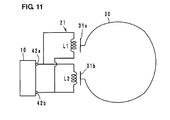
- FIG. 11 is an equivalent circuit diagram including a power feeding circuit and a radiation plate according to the second preferred embodiment of the present invention.
- FIG. 12 is a plan view illustrating a laminated structure of an example of a modification to the power feeding circuit substrate.
- FIG. 13 is an equivalent circuit diagram including an example of a modification to the power feeding circuit substrate, illustrated in FIG. 12 , and the radiation plate.
- FIG. 14 is a pattern diagram for explaining the change of impedance of the radiation plate.
- FIG. 15 is a perspective view illustrating a wireless IC device according to a third preferred embodiment of the present invention.
- FIG. 16 is an exploded plan view illustrating a structure of a radiation plate according to the third preferred embodiment of the present invention.
- FIGS. 17A-17E are explanatory diagrams illustrating a coupling method for the power feeding circuit and the radiation plate according to the third preferred embodiment of the present invention.
- FIGS. 18A-18C are explanatory diagrams illustrating a coupling method for the power feeding circuit and the radiation plate according to the third preferred embodiment of the present invention and the continuation of FIGS. 17A-17E .
- a wireless IC device that is a first preferred embodiment is a device used in a UHF band, and, as illustrated in FIG. 1 , includes a wireless IC chip 10 processing a transmission/reception signal of a predetermined frequency, a power feeding circuit substrate 20 mounted with the wireless IC chip 10 , and two radiation plates 30 A and 30 B.
- the power feeding circuit substrate 20 includes a power feeding circuit 21 including a resonant circuit/matching circuit in which inductance elements L 1 and L 2 are included that have substantially the same inductance values and preferably have spiral shapes wound in directions opposite to each other.
- the winding axes of the inductance elements L 1 and L 2 are disposed at different positions and parallel or substantially parallel to each other, in plan view.
- the wireless IC chip 10 includes a clock circuit, a logic circuit, a memory circuit, and the like, necessary information is stored therein, and a pair of input-output terminal electrodes and a pair of mounting terminal electrodes, not illustrated, are provided on the rear surface thereof.
- the input-output terminal electrodes are electrically connected to power feeding terminal electrodes 122 a and 122 b located on the power feeding circuit substrate 20 through metal bumps or the like, and the mounting terminal electrodes are electrically connected to mounting electrodes 123 a and 123 b through metal bumps or the like, for example.
- the wireless IC chip 10 and the power feeding circuit 21 are not electrically connected to each other, and are coupled (electromagnetically coupled) with each other.
- the radiation plates 30 A and 30 B preferably are individually arranged to have meander shapes on a flexible resin film (not illustrated), and include non-magnetic metal material. End portions of the radiation plates 30 A and 30 B are regarded as plate-shaped coupling units 31 a and 31 b , and the power feeding circuit substrate 20 is stuck onto the coupling units 31 a and 31 b .
- the plate-shaped coupling unit 31 a is disposed in a vicinity of the inductance element L 1 so as to be perpendicular or substantially perpendicular to the winding axis of the inductance element L 1
- the plate-shaped coupling unit 31 b is disposed in a vicinity of the inductance element L 2 so as to be perpendicular to the winding axis of the inductance element L 2 .
- the inductance elements L 1 and L 2 included in the power feeding circuit 21 are magnetically coupled with each other in a reverse phase to resonate with a frequency processed by the wireless IC chip 10 , and coupled with the coupling units 31 a and 31 b in the radiation plates 30 A and 30 B owing to eddy currents, in such a way as described later.
- the power feeding circuit 21 establishes matching between the impedance of the wireless IC chip 10 and the impedances of the radiation plates 30 A and 30 B.
- the inductance values of the inductance elements L 1 and L 2 may be different from each other, or may be substantially equal to each other. When the inductance value of the inductance elements L 1 and L 2 are caused to be substantially equal to each other, the leakage magnetic field of a closed loop is reduced, and it is possible to reduce a coupling loss.
- the coupling between the power feeding circuit 21 and the radiation plates 30 A and 30 B will be described with reference to FIGS. 5A-5F .
- the inductance elements L 1 and L 2 are wound in directions opposite to each other (refer to FIG. 5A ) and the current paths thereof are mirror-reversed, magnetic fields are also reversed, and a far magnetic field becomes zero. Therefore, the power feeding circuit substrate 20 does not function as an antenna.
- the elements L 1 and L 2 are wound in directions opposite to each other, a magnetic field flows as one closed loop, and does not leak to the outside (refer to FIG. 5B ). Accordingly, a portion of energy is not radiated further other than coupling as in normal magnetic field coupling.
- Electrons for the neutralization of a magnetic field attempt to flow from one end portion to the other end portion with originating from the secondary magnetic field B.
- currents flow into and from the adjacent coupling units 31 a and 31 b from and to the outside, and currents flow through the radiation plates 30 A and 30 B (refer to FIG. 5F ).
- a current also flows through a loop-shaped radiation plate 30 .
- the path length of a radiation plate is not influenced.
- that a radiation plate is divided into two plates or is one loop-shaped plate does not influence a coupling efficiency.
- the path lengths of the radiation plates 30 A and 30 B area about ⁇ /4 (a total path length is about ⁇ /2)
- a voltage becomes a maximum and a current becomes a minimum at an end portion, and a resonance condition is satisfied. Therefore, it is easier for a current to flow.
- eddy currents flow through the radiation plates 30 A and 30 B with originating from the facing plate-shaped coupling units 31 a and 31 b .
- a magnetic field perpendicularly runs into the plate-shaped coupling units 31 a and 31 b , thereby actively generating eddy currents, and hence energy causing a current to flow through the radiation plates 30 A and 30 B occurs with originating from adjacent eddy currents.
- Such transmission (coupling) of energy is realized when a plate perpendicularly or substantially perpendicularly facing a pair of coils whose directions are opposite to each other is disposed and eddy currents flows through the plate. Accordingly, even if a plate-shaped coupling unit is only disposed for one of the inductance elements L 1 and L 2 , it is difficult to transmit energy to the radiation plate.
- the above-mentioned new coupling method based on the eddy currents does not depend on a frequency if a magnetic field is strong, and in an HF band such as 13.56 MHz or the like which is a low frequency, it is also possible to couple the power feeding circuit 21 with the radiation plates 30 A and 30 B. Also in a high-frequency wave, an efficiency of transmitting energy to the radiation plates 30 A and 30 B is high, and even the small power feeding circuit substrate 20 can realize a degree of coupling ranging from about 0.8 to about 1.0 (specifically, greater than or equal to about 0.96) with respect to the plate-shaped coupling units 31 a and 31 b , for example.
- the degree of coupling is a value converted on the basis of a minimum driving power that is about ⁇ 14.7 dBm at the time of direct coupling in which the power feeding circuit 21 is DC-connected to the radiation plates 30 A and 30 B and about ⁇ 11.5 dBm at the time of the present coupling due to the eddy currents.
- the resistance component and the dielectric loss (tan ⁇ ) of the coil-shaped electrode pattern may be considered.
- the deviations of the inductance values of the inductance elements L 1 and L 2 also causes the occurrence of the leakage magnetic field of the closed loop, and causes a coupling loss.
- the power feeding circuit 21 transmits, to the radiation plates 30 A and 30 B, a transmission signal having a predetermined frequency, transmitted from the wireless IC chip 10 , and selects a reception signal having a predetermined frequency from a signal received by the radiation plates 30 A and 30 B to supply the selected signal to the wireless IC chip 10 . Therefore, in the wireless IC device, the wireless IC chip 10 is caused to operate by the signal received by the radiation plates 30 A and 30 B, and a response signal from the wireless IC chip 10 is radiated from the radiation plates 30 A and 30 B to the outside.
- the frequency of the signal is set by the power feeding circuit 21 provided in the power feeding circuit substrate 20 . Therefore, even if the present wireless IC device is attached to various kinds of goods, the present wireless IC device operates without change, the fluctuation of a radiation characteristic is suppressed, and it is not necessary to perform the design change of the radiation plates 30 A and 30 B or the like, with respect to individual goods.
- the frequency of the transmission signal radiated from the radiation plates 30 A and 30 B and the frequency of the reception signal supplied to the wireless IC chip 10 substantially correspond to the resonance frequency of the power feeding circuit 21 in the power feeding circuit substrate 20 , and the maximum gain of a signal is substantially determined by at least one of the size and the shape of the power feeding circuit 21 , a distance between the power feeding circuit and the radiation plates 30 A and 30 B, and a medium.
- the frequency of the transmission/reception signal is determined in the power feeding circuit substrate 20 , without depending on the shapes and the sizes of the radiation plates 30 A and 30 B, a disposition relationship therebetween, or the like, it is possible to obtain a stable frequency characteristic without the frequency characteristic being changed, even if the wireless IC device is rolled or sandwiched between dielectric materials, for example.
- the power feeding circuit substrate 20 is preferably obtained by laminating, crimping, and firing ceramic sheets 121 a to 121 g including dielectric material or magnetic material, for example.
- the power feeding terminal electrodes 122 a and 122 b and the mounting electrodes 123 a and 123 b are located on the sheet 121 a in an uppermost layer, and wiring electrodes 125 a and 125 b are located on the sheet 121 b to 121 g.
- the inductance elements L 1 and L 2 are formed preferably by individually connecting the wiring electrodes 125 a and 125 b having spiral shapes through via hole conductors, and integrated using the wiring electrodes 125 a and 125 b on the sheet 121 b .
- An end portion 125 a ′ of the wiring electrode 125 a on the sheet 121 g is connected to the power feeding terminal electrode 122 a through a via hole conductor, and an end portion 125 b ′ of the wiring electrode 125 b on the sheet 121 g is connected to the power feeding terminal electrode 122 b through a via hole conductor.
- FIG. 6 illustrates an example of a modification to the power feeding circuit substrate 20 .
- the power feeding circuit substrate 20 is obtained preferably by providing the sheet 121 h in the lowermost layer of the laminated structure illustrated in FIG. 3 and forming flat electrodes 128 a and 128 b on the sheet 121 h .
- FIG. 7 illustrates the equivalent circuit thereof.
- each of a pair of the flat electrode 128 a and the plate-shaped coupling unit 31 a and a pair of the flat electrode 128 b and the plate-shaped coupling unit 31 b functions as a plate blocking a magnetic field. Accordingly, currents flow through the radiation plates 30 A and 30 B.
- the flat electrodes 128 a and 128 b may be formed on the outer surface (the rear surface of the sheet 121 h ) of the power feeding circuit substrate 20 . By forming the flat electrodes 128 a and 128 b on the outer surface, it is possible to use the flat electrodes 128 a and 128 b as mounting electrodes.
- a radiation plate 30 including the plate-shaped coupling units 31 a and 31 b is loop-shaped, and the other components are preferably the same as those of the first preferred embodiment.
- the plate-shaped coupling units 31 a and 31 b are perpendicularly or substantially perpendicularly disposed in a vicinity of the inductance elements L 1 and L 2 wound in directions opposite to each other, and hence the power feeding circuit 21 is coupled with the plate-shaped coupling units 31 a and 31 b owing to eddy currents, and a current flows through the loop-shaped radiation plate 30 . This is the same as described in the first preferred embodiment.
- FIG. 11 illustrates an equivalent circuit in the present second preferred embodiment.
- the power feeding circuit substrate 20 a power feeding circuit substrate having a laminated structure illustrated in FIG. 10 is preferably used as the power feeding circuit substrate 20 . More specifically, the power feeding circuit substrate 20 is obtained preferably by laminating, crimping, and firing ceramic sheets 41 a to 41 h including dielectric material or magnetic material. Power feeding terminal electrodes 42 a and 42 b , mounting electrodes 43 a and 43 b , and via hole conductors 44 a , 44 b , 45 a , and 45 b are formed on the sheet 41 a in an uppermost layer.
- Wiring electrodes 46 a and 46 b configuring the inductance elements L 1 and L 2 are formed on each of the sheet 41 b in a second layer to the sheet 41 h in an eighth layer, and via hole conductors 47 a , 47 b , 48 a , and 48 b are formed when necessary.
- the inductance element L 1 is located where the wiring electrodes 46 a are connected in a spiral shape through the via hole conductor 47 a
- the inductance element L 2 is located where the wiring electrodes 46 b are connected in a spiral shape through the via hole conductor 47 b .
- capacitance is generated between the lines of the wiring electrodes 46 a and 46 b.
- An end portion 46 a - 1 of the wiring electrode 46 a on the sheet 41 b is connected to the power feeding terminal electrode 42 a through the via hole conductor 45 a
- an end portion 46 a - 2 of the wiring electrode 46 a on the sheet 41 h is connected to the power feeding terminal electrode 42 b through the via hole conductors 48 a and 45 b
- An end portion 46 b - 1 of the wiring electrode 46 b on the sheet 41 b is connected to the power feeding terminal electrode 42 b through the via hole conductor 44 b
- an end portion 46 b - 2 of the wiring electrode 46 b on the sheet 41 h is connected to the power feeding terminal electrode 42 a through the via hole conductors 48 b and 44 a.
- the power feeding terminal electrodes 42 a and 42 b are electrically connected to the input-output terminal electrodes in the wireless IC chip 10
- the mounting electrodes 43 a and 43 b are electrically connected to mounting terminal electrode in the wireless IC chip 10 .
- FIG. 12 illustrates an example of a modification to the power feeding circuit substrate 20
- FIG. 13 illustrates the equivalent circuit thereof.
- the power feeding circuit substrate 20 is obtained preferably by providing flat electrodes 49 a and 49 b on the rear surface of the sheet 41 i provided in the lowermost layer of the power feeding circuit substrate 20 illustrated in FIG. 10 , the outer shapes of the flat electrodes 49 a and 49 b being equal to or smaller than those of the inductance elements L 1 and L 2 when the perspective plane of the power feeding circuit substrate 20 is viewed.
- each of a pair of the flat electrode 49 a and the plate-shaped coupling unit 31 a and a pair of the flat electrode 49 b and the plate-shaped coupling unit 31 b functions as a plate blocking a magnetic field. Accordingly, a current flows through the radiation plate 30 .
- a wireless IC device includes a wireless IC chip 10 , a power feeding circuit substrate 20 mounted with the wireless IC chip 10 , and two linear radiation plates 30 A and 30 B.
- the power feeding circuit substrate 20 is preferably the same as that illustrated in the first preferred embodiment (with respect to the inner structure, refer to FIG. 3 , for example).
- End portions of the radiation plates 30 A and 30 B are preferably spiral-shaped coupling units 32 a and 32 b , respectively.
- the spiral-shaped coupling units 32 a and 32 b are disposed in a vicinity of the two inductance elements L 1 and L 2 (refer to the first preferred embodiment) so that the spiral surfaces thereof are perpendicular or substantially perpendicular to the winding axes of the inductance elements L 1 and L 2 , respectively, and the spiral-shaped coupling units 32 a and 32 b are wound in directions opposite to the winding directions of the adjacent inductance elements L 1 and L 2 , respectively. More specifically, the inductance elements L 1 and L 2 are coupled with the spiral-shaped coupling units 32 a and 32 b owing to eddy currents, as described below.
- eddy currents A occur in the coupling units 32 a and 32 b (refer to FIG. 18A ). Since the coupling units 32 a and 32 b are adjacent to each other and directions in which the eddy currents A flow are opposite to each other in adjacent portions, a closed-loop secondary magnetic field B occurs (refer to FIG. 18B ). Electrons for the neutralization of a magnetic field attempt to flow from one end portion to the other end portion with originating from the secondary magnetic field B. In addition, even if the radiation plates 30 A and 30 B are separated into two portions, currents flow into and from the adjacent coupling units 32 a and 32 b from and to the outside, and currents flow through the radiation plates 30 A and 30 B (refer to FIG. 18C ).
- the coupling units 32 a and 32 b receive the magnetic field B, and a current I occurs and receives a force F.
- the force F received by electrons turns out to have the same direction, as the radiation plates 30 A and 30 B, and currents turn out to flow through the radiation plates 30 A and 30 B.
- End portions of the radiation plates 30 A and 30 B are connected to end portions of the loop-shaped wiring electrodes 131 a and 131 b , respectively, and the other end portions of the electrodes 131 a and 131 b are connected to end portions of loop-shaped wiring electrodes 132 a and 132 b in the second layer through via hole conductors 135 a and 135 b .
- the other end portions of the electrodes 132 a and 132 b are connected to a wiring electrode 133 in the third layer through via hole conductors 136 a and 136 b .
- the spiral-shaped coupling units 32 a and 32 b are interlinked through the electrode 133 , and the radiation plates 30 A and 30 B turn out to be formed using one conductive wire. If the wavelength of a signal is ⁇ , it is desirable that the lengths of such radiation plates 30 A and 30 B are the integral multiple of ⁇ /2.
- the spiral-shaped coupling units 32 a and 32 b have been illustrated preferably as structures in which wiring electrodes are formed and laminated in a substrate.
- the spiral-shaped coupling units 32 a and 32 b may also be configured by shaping a copper line into a spiral shape.
- the wireless IC device and the coupling method according to the present invention are not limited to the above-mentioned preferred embodiments, and it should be understood that various other preferred embodiments, and combinations and modifications thereof may occur insofar as they are within the scope thereof.
- the wireless IC may not be a chip type, and may be formed in the power feeding circuit substrate in an integrated fashion.
- various shapes may be adopted for the radiation plate.
- preferred embodiments of the present invention are useful for a wireless IC device, and in particular, are superior in terms of being capable of coupling a power feeding circuit with a radiation plate with a very high degree of coupling due to eddy currents.
Abstract
Description
Claims (4)
Applications Claiming Priority (5)
| Application Number | Priority Date | Filing Date | Title |
|---|---|---|---|
| JP2009-147060 | 2009-06-19 | ||
| JP2009147060 | 2009-06-19 | ||
| JP2009-233195 | 2009-10-07 | ||
| JP2009233195 | 2009-10-07 | ||
| PCT/JP2010/057668 WO2010146944A1 (en) | 2009-06-19 | 2010-04-30 | Wireless ic device and method for coupling power supply circuit and radiating plates |
Related Parent Applications (1)
| Application Number | Title | Priority Date | Filing Date |
|---|---|---|---|
| PCT/JP2010/057668 Continuation WO2010146944A1 (en) | 2009-06-19 | 2010-04-30 | Wireless ic device and method for coupling power supply circuit and radiating plates |
Publications (2)
| Publication Number | Publication Date |
|---|---|
| US20120086526A1 US20120086526A1 (en) | 2012-04-12 |
| US8810456B2 true US8810456B2 (en) | 2014-08-19 |
Family
ID=43356268
Family Applications (1)
| Application Number | Title | Priority Date | Filing Date |
|---|---|---|---|
| US13/325,273 Active 2031-05-07 US8810456B2 (en) | 2009-06-19 | 2011-12-14 | Wireless IC device and coupling method for power feeding circuit and radiation plate |
Country Status (3)
| Country | Link |
|---|---|
| US (1) | US8810456B2 (en) |
| JP (1) | JP5516580B2 (en) |
| WO (1) | WO2010146944A1 (en) |
Cited By (2)
| Publication number | Priority date | Publication date | Assignee | Title |
|---|---|---|---|---|
| US20160217905A1 (en) * | 2015-01-27 | 2016-07-28 | Samsung Electro-Mechanics Co., Ltd. | Coil component and method of manufacturing the same |
| US11392784B2 (en) * | 2010-03-24 | 2022-07-19 | Murata Manufacturing Co., Ltd. | RFID system |
Families Citing this family (4)
| Publication number | Priority date | Publication date | Assignee | Title |
|---|---|---|---|---|
| CN103348531B (en) * | 2011-01-20 | 2016-06-08 | 株式会社村田制作所 | Frequency stabilization circuit, antenna assembly and communication terminal |
| CN106462792B (en) | 2014-11-27 | 2019-07-05 | 株式会社村田制作所 | RFIC module and the RFID label tag for having the RFIC module |
| WO2018101174A1 (en) * | 2016-11-30 | 2018-06-07 | 京セラ株式会社 | Antenna, module substrate, and module |
| JP7243931B2 (en) * | 2020-11-30 | 2023-03-22 | 株式会社村田製作所 | CONTAINER WITH RFID MODULE AND METHOD FOR MANUFACTURING CONTAINER WITH RFID MODULE |
Citations (335)
| Publication number | Priority date | Publication date | Assignee | Title |
|---|---|---|---|---|
| US3364564A (en) | 1965-06-28 | 1968-01-23 | Gregory Ind Inc | Method of producing welding studs dischargeable in end-to-end relationship |
| US4794397A (en) | 1984-10-13 | 1988-12-27 | Toyota Jidosha Kabushiki Kaisha | Automobile antenna |
| NL9100347A (en) | 1991-02-26 | 1992-03-02 | Nedap Nv | Integrated transformer circuit for ID or credit card - is interrogated via contactless inductive coupling using capacitor to form tuned circuit |
| NL9100176A (en) | 1991-02-01 | 1992-03-02 | Nedap Nv | Antenna configuration for contactless identification label - forms part of tuned circuit of ID or credit card interrogated via inductive coupling |
| US5232765A (en) | 1990-07-25 | 1993-08-03 | Ngk Insulators, Ltd. | Distributed constant circuit board using ceramic substrate material |
| US5253969A (en) | 1989-03-10 | 1993-10-19 | Sms Schloemann-Siemag Aktiengesellschaft | Feeding system for strip material, particularly in treatment plants for metal strips |
| US5337063A (en) | 1991-04-22 | 1994-08-09 | Mitsubishi Denki Kabushiki Kaisha | Antenna circuit for non-contact IC card and method of manufacturing the same |
| US5374937A (en) | 1991-07-08 | 1994-12-20 | Nippon Telegraph And Telephone Corporation | Retractable antenna system |
| EP0694874A2 (en) | 1994-07-25 | 1996-01-31 | Toppan Printing Co., Ltd. | Biodegradable cards |
| US5491483A (en) | 1994-01-05 | 1996-02-13 | Texas Instruments Incorporated | Single loop transponder system and method |
| US5528222A (en) | 1994-09-09 | 1996-06-18 | International Business Machines Corporation | Radio frequency circuit and memory in thin flexible package |
| GB2305075A (en) | 1995-09-05 | 1997-03-26 | Ibm | Radio Frequency Tag for Electronic Apparatus |
| US5757074A (en) | 1995-07-07 | 1998-05-26 | Hughes Electronics Corporation | Microwave/millimeter wave circuit structure with discrete flip-chip mounted elements |
| EP0848448A2 (en) | 1996-12-10 | 1998-06-17 | Murata Manufacturing Co., Ltd. | Surface mount type antenna and communication apparatus |
| CA2279176A1 (en) | 1997-01-28 | 1998-07-30 | Amatech Advanced Micromechanic & Automation Technology Gmbh & Co. Kg | Transmission module for a transponder device, and also a transponder device and method of operating a transponder device |
| US5854480A (en) | 1995-07-18 | 1998-12-29 | Oki Electric Indusry Co., Ltd. | Tag with IC capacitively coupled to antenna |
| US5903239A (en) | 1994-08-11 | 1999-05-11 | Matsushita Electric Industrial Co., Ltd. | Micro-patch antenna connected to circuits chips |
| US5936150A (en) | 1998-04-13 | 1999-08-10 | Rockwell Science Center, Llc | Thin film resonant chemical sensor with resonant acoustic isolator |
| US5955723A (en) | 1995-05-03 | 1999-09-21 | Siemens Aktiengesellschaft | Contactless chip card |
| EP0948083A2 (en) | 1998-03-31 | 1999-10-06 | Kabushiki Kaisha Toshiba | Loop antenna device and its use in a data processing apparatus with a removal data storing medium |
| JP2000021639A (en) | 1998-07-02 | 2000-01-21 | Sharp Corp | Inductor, resonance circuit using the same, matching circuit, antenna circuit, and oscillation circuit |
| JP2000022421A (en) | 1998-07-03 | 2000-01-21 | Murata Mfg Co Ltd | Chip antenna and radio device mounted with it |
| EP0977145A2 (en) | 1998-07-28 | 2000-02-02 | Kabushiki Kaisha Toshiba | Radio IC card |
| JP2000059260A (en) | 1998-08-04 | 2000-02-25 | Sony Corp | Storage device |
| JP2000085283A (en) | 1998-09-16 | 2000-03-28 | Dainippon Printing Co Ltd | Noncontact ic card and its manufacture |
| JP2000090207A (en) | 1998-09-08 | 2000-03-31 | Toppan Printing Co Ltd | Device and method for checking non-contact ic card |
| JP2000132643A (en) | 1998-10-23 | 2000-05-12 | Toppan Printing Co Ltd | Inspecting device for non-contact ic card and its method |
| JP2000137785A (en) | 1998-10-30 | 2000-05-16 | Sony Corp | Manufacture of noncontact type ic card and noncontact type ic card |
| JP2000137778A (en) | 1998-10-30 | 2000-05-16 | Denso Corp | Id tag for dish type article |
| JP2000137779A (en) | 1998-10-30 | 2000-05-16 | Hitachi Maxell Ltd | Non-contact information medium and production thereof |
| JP2000148948A (en) | 1998-11-05 | 2000-05-30 | Sony Corp | Non-contact ic label and its manufacture |
| EP1010543A1 (en) | 1996-12-27 | 2000-06-21 | Rohm Co., Ltd. | Card mounted with circuit chip and circuit chip module |
| JP2000172812A (en) | 1998-12-08 | 2000-06-23 | Hitachi Maxell Ltd | Noncontact information medium |
| JP2000209013A (en) | 1999-01-14 | 2000-07-28 | Nec Saitama Ltd | Mobile radio terminal and built-in antenna |
| JP2000222540A (en) | 1999-02-03 | 2000-08-11 | Hitachi Maxell Ltd | Non-contact type semiconductor tag |
| US6104611A (en) | 1995-10-05 | 2000-08-15 | Nortel Networks Corporation | Packaging system for thermally controlling the temperature of electronic equipment |
| US6107920A (en) | 1998-06-09 | 2000-08-22 | Motorola, Inc. | Radio frequency identification tag having an article integrated antenna |
| JP2000243797A (en) | 1999-02-18 | 2000-09-08 | Sanken Electric Co Ltd | Semiconductor wafer, and cutting method thereof, and semiconductor wafer assembly and cutting method thereof |
| JP2000242754A (en) | 1999-02-23 | 2000-09-08 | Toshiba Corp | Ic card |
| JP2000251049A (en) | 1999-03-03 | 2000-09-14 | Konica Corp | Card and production thereof |
| JP2000261230A (en) | 1999-03-05 | 2000-09-22 | Smart Card Technologies:Kk | Coil unit and antenna system using the same and printed circuit board |
| JP2000276569A (en) | 1999-03-26 | 2000-10-06 | Dainippon Printing Co Ltd | Ic chip and memory medium having the same built in |
| JP2000286760A (en) | 1999-03-31 | 2000-10-13 | Toyota Autom Loom Works Ltd | Coupler for mobile communication, mobile object and communication method for mobile object |
| JP2000286634A (en) | 1999-03-30 | 2000-10-13 | Ngk Insulators Ltd | Antenna system and its manufacture |
| JP2000311226A (en) | 1998-07-28 | 2000-11-07 | Toshiba Corp | Radio ic card and its production and read and write system of the same |
| JP2000321984A (en) | 1999-05-12 | 2000-11-24 | Hitachi Ltd | Label with rf-id tag |
| JP2000349680A (en) | 1999-03-30 | 2000-12-15 | Ngk Insulators Ltd | Transmitter-receiver |
| US6172608B1 (en) | 1996-06-19 | 2001-01-09 | Integrated Silicon Design Pty. Ltd. | Enhanced range transponder system |
| US6181287B1 (en) | 1997-03-10 | 2001-01-30 | Precision Dynamics Corporation | Reactively coupled elements in circuits on flexible substrates |
| JP2001028036A (en) | 1999-07-14 | 2001-01-30 | Shinko Electric Ind Co Ltd | Semiconductor device and its manufacture |
| JP2001043340A (en) | 1999-07-29 | 2001-02-16 | Toppan Printing Co Ltd | Composite ic card |
| JP3075400U (en) | 2000-08-03 | 2001-02-16 | 昌栄印刷株式会社 | Non-contact IC card |
| US6190942B1 (en) | 1996-10-09 | 2001-02-20 | Pav Card Gmbh | Method and connection arrangement for producing a smart card |
| JP2001101369A (en) | 1999-10-01 | 2001-04-13 | Matsushita Electric Ind Co Ltd | Rf tag |
| US6249258B1 (en) | 1995-09-15 | 2001-06-19 | Aeg Identifikationssysteme | Transponder arrangement |
| JP2001168628A (en) | 1999-12-06 | 2001-06-22 | Smart Card Technologies:Kk | Auxiliary antenna for ic card |
| JP2001188890A (en) | 2000-01-05 | 2001-07-10 | Omron Corp | Non-contact tag |
| US6259369B1 (en) | 1999-09-30 | 2001-07-10 | Moore North America, Inc. | Low cost long distance RFID reading |
| JP2001240046A (en) | 2000-02-25 | 2001-09-04 | Toppan Forms Co Ltd | Container and manufacturing method thereof |
| JP2001257292A (en) | 2000-03-10 | 2001-09-21 | Hitachi Maxell Ltd | Semiconductor device |
| JP2001256457A (en) | 2000-03-13 | 2001-09-21 | Toshiba Corp | Semiconductor device, its manufacture and ic card communication system |
| JP2001319380A (en) | 2000-05-11 | 2001-11-16 | Mitsubishi Materials Corp | Optical disk with rfid |
| JP2001331976A (en) | 2000-05-17 | 2001-11-30 | Casio Comput Co Ltd | Optical recording type recording medium |
| JP2001332923A (en) | 2000-05-19 | 2001-11-30 | Dx Antenna Co Ltd | Film antenna |
| EP1160915A2 (en) | 2000-05-30 | 2001-12-05 | Mitsubishi Materials Corporation | Antenna device of interrogator |
| JP2001339226A (en) | 2000-05-26 | 2001-12-07 | Nec Saitama Ltd | Antenna system |
| JP2001351083A (en) | 2000-04-04 | 2001-12-21 | Dainippon Printing Co Ltd | Noncontact data carrier device and auxiliary antenna |
| JP2001351084A (en) | 2000-04-04 | 2001-12-21 | Dainippon Printing Co Ltd | Noncontact data carrier device and auxiliary antenna |
| JP2001352176A (en) | 2000-06-05 | 2001-12-21 | Fuji Xerox Co Ltd | Multilayer printed wiring board and manufacturing method of multilayer printed wiring board |
| US6335686B1 (en) | 1998-08-14 | 2002-01-01 | 3M Innovative Properties Company | Application for a radio frequency identification system |
| EP1170795A2 (en) | 2000-07-06 | 2002-01-09 | Murata Manufacturing Co., Ltd. | Electronic component with side contacts and associated method of fabrication |
| JP2002024776A (en) | 2000-07-07 | 2002-01-25 | Nippon Signal Co Ltd:The | Ic card reader/writer |
| US20020015002A1 (en) | 2000-06-23 | 2002-02-07 | Hidenori Yasukawa | Antenna coil for IC card and manufacturing method thereof |
| JP2002042076A (en) | 2000-07-21 | 2002-02-08 | Dainippon Printing Co Ltd | Non-contact data carrier and booklet therewith |
| JP2002505645A (en) | 1998-04-14 | 2002-02-19 | リバティ・カートン・カンパニー−テキサス | Container for compressors and other goods |
| JP2002063557A (en) | 2000-08-21 | 2002-02-28 | Mitsubishi Materials Corp | Tag for rfid |
| JP2002076750A (en) | 2000-08-24 | 2002-03-15 | Murata Mfg Co Ltd | Antenna device and radio equipment equipped with it |
| US6362784B1 (en) | 1998-03-31 | 2002-03-26 | Matsuda Electric Industrial Co., Ltd. | Antenna unit and digital television receiver |
| EP1193793A2 (en) | 2000-09-28 | 2002-04-03 | Hitachi Kokusai Electric Inc. | Antenna |
| US6367143B1 (en) | 1998-03-10 | 2002-04-09 | Smart Card Technologies Co. Ltd. | Coil element and method for manufacturing thereof |
| US6378774B1 (en) | 1997-11-14 | 2002-04-30 | Toppan Printing Co., Ltd. | IC module and smart card |
| JP2002150245A (en) | 2000-10-19 | 2002-05-24 | Samsung Sds Co Ltd | Ic module for ic card and ic card using the same |
| JP2002157564A (en) | 2000-11-21 | 2002-05-31 | Toyo Aluminium Kk | Antenna coil for ic card and its manufacturing method |
| JP2002158529A (en) | 2000-11-20 | 2002-05-31 | Murata Mfg Co Ltd | Surface-mounted antenna structure and communications equipment provided with the same |
| US20020067316A1 (en) | 2000-10-27 | 2002-06-06 | Mitsubishi Materials Corporation | Antenna |
| US6406990B1 (en) | 1999-11-24 | 2002-06-18 | Omron Corporation | Method of mounting a semiconductor chip, circuit board for flip-chip connection and method of manufacturing the same, electromagnetic wave readable data carrier and method of manufacturing the same, and electronic component module for an electromagnetic wave readable data carrier |
| JP2002175508A (en) | 2000-12-07 | 2002-06-21 | Dainippon Printing Co Ltd | Non-contact type data carrier device, and wiring member for booster antenna part |
| JP2002183690A (en) | 2000-12-11 | 2002-06-28 | Hitachi Maxell Ltd | Noncontact ic tag device |
| JP2002185358A (en) | 2000-11-24 | 2002-06-28 | Supersensor Pty Ltd | Method for fitting rf transponder to container |
| US20020093457A1 (en) | 2001-01-12 | 2002-07-18 | Hiroki Hamada | Antenna device |
| JP2002522849A (en) | 1998-08-14 | 2002-07-23 | スリーエム イノベイティブ プロパティズ カンパニー | Radio Frequency Identification System Applications |
| EP1227540A1 (en) | 2001-01-30 | 2002-07-31 | Alps Electric Co., Ltd. | Partial ground connection of a metal housing for realising certain electrical lenghts for the ground connection of a chip antenna |
| JP2002230128A (en) | 2001-02-05 | 2002-08-16 | Dainippon Printing Co Ltd | Goods with coil-on-chip type semiconductor module and sale system |
| JP2002252117A (en) | 2000-12-19 | 2002-09-06 | Murata Mfg Co Ltd | Laminated coil component and its manufacturing method |
| US6448874B1 (en) | 1999-02-08 | 2002-09-10 | Alps Electric Co., Ltd. | Resonant line constructed by microstrip line which is easy to be trimmed |
| JP2002259934A (en) | 2001-03-06 | 2002-09-13 | Dainippon Printing Co Ltd | Liquid container with rfid tag |
| US6452563B1 (en) | 1998-12-22 | 2002-09-17 | Gemplus | Antenna arrangement in a metallic environment |
| JP2002280821A (en) | 2001-01-12 | 2002-09-27 | Furukawa Electric Co Ltd:The | Antenna system and terminal equipment |
| JP2002298109A (en) | 2001-03-30 | 2002-10-11 | Toppan Forms Co Ltd | Contactless ic medium and manufacturing method thereof |
| JP2002308437A (en) | 2001-04-16 | 2002-10-23 | Dainippon Printing Co Ltd | Inspection system using rfid tag |
| JP2002319008A (en) | 2001-04-23 | 2002-10-31 | Hanex Chuo Kenkyusho:Kk | Rfid tag structure and method of manufacturing it |
| JP2002319009A (en) | 2001-04-23 | 2002-10-31 | Hanex Chuo Kenkyusho:Kk | Rfid tag structure and electromagnetic coupler of rfid tag |
| JP2002319812A (en) | 2001-04-20 | 2002-10-31 | Oji Paper Co Ltd | Data carrier adhesion method |
| JP2002362613A (en) | 2001-06-07 | 2002-12-18 | Toppan Printing Co Ltd | Laminated packaging material having non-contact ic, packaging container using laminated packaging material and method for detecting opened seal of packaging container |
| JP2002366917A (en) | 2001-06-07 | 2002-12-20 | Hitachi Ltd | Ic card incorporating antenna |
| JP2002373323A (en) | 2001-06-18 | 2002-12-26 | Dainippon Printing Co Ltd | Card incorporated form with non-contact ic chip |
| JP2002374139A (en) | 2001-06-13 | 2002-12-26 | Murata Mfg Co Ltd | Balance type lc filter |
| JP2002373029A (en) | 2001-06-18 | 2002-12-26 | Hitachi Ltd | Method for preventing illegal copy of software by using ic tag |
| US20030006901A1 (en) | 2000-07-04 | 2003-01-09 | Ji-Tae Kim | Passive transponder identification and credit-card type transponder |
| JP2003006599A (en) | 2001-06-19 | 2003-01-10 | Teraoka Seiko Co Ltd | Method for mounting ic tag on metal object and marker with built-in ic tag |
| JP2003016412A (en) | 2001-07-03 | 2003-01-17 | Hitachi Chem Co Ltd | Ic module, ic label, and ic card |
| JP2003022912A (en) | 2001-03-30 | 2003-01-24 | Mitsubishi Materials Corp | Antenna coil, identification tag using the same, reader- writer apparatus, reader and writer |
| EP1280232A1 (en) | 2001-07-27 | 2003-01-29 | TDK Corporation | Antenna device capable of being commonly used at a plurality of frequencies and electronic equipment having the same |
| EP1280350A1 (en) | 2001-07-26 | 2003-01-29 | Irdeto Access B.V. | Time validation system |
| JP2003026177A (en) | 2001-07-12 | 2003-01-29 | Toppan Printing Co Ltd | Packaging member with non-contact type ic chip |
| JP2003030612A (en) | 2001-07-19 | 2003-01-31 | Oji Paper Co Ltd | Ic chip mounting body |
| US20030045324A1 (en) | 2001-08-30 | 2003-03-06 | Murata Manufacturing Co., Ltd. | Wireless communication apparatus |
| JP2003069335A (en) | 2001-08-28 | 2003-03-07 | Hitachi Kokusai Electric Inc | Auxiliary antenna |
| JP2003067711A (en) | 2001-08-29 | 2003-03-07 | Toppan Forms Co Ltd | Article provided with ic chip mounting body or antenna part |
| JP2003076947A (en) | 2001-09-05 | 2003-03-14 | Toppan Forms Co Ltd | Rf-id inspection system |
| JP2003078336A (en) | 2001-08-30 | 2003-03-14 | Tokai Univ | Laminated spiral antenna |
| JP2003085501A (en) | 2001-09-07 | 2003-03-20 | Dainippon Printing Co Ltd | Non-contact ic tag |
| JP2003085520A (en) | 2001-09-11 | 2003-03-20 | Oji Paper Co Ltd | Manufacturing method for ic card |
| US6542050B1 (en) | 1999-03-30 | 2003-04-01 | Ngk Insulators, Ltd. | Transmitter-receiver |
| JP2003099721A (en) | 2001-09-25 | 2003-04-04 | Toppan Forms Co Ltd | Inspection system for rf-id |
| JP2003099720A (en) | 2001-09-25 | 2003-04-04 | Toppan Forms Co Ltd | Inspection system for rf-id |
| JP2003110344A (en) | 2001-09-26 | 2003-04-11 | Hitachi Metals Ltd | Surface-mounting type antenna and antenna device mounting the same |
| JP2003134007A (en) | 2001-10-30 | 2003-05-09 | Auto Network Gijutsu Kenkyusho:Kk | System and method for exchanging signal between on- vehicle equipment |
| JP2003132330A (en) | 2001-10-25 | 2003-05-09 | Sato Corp | Rfid label printer |
| JP2003155062A (en) | 2001-11-20 | 2003-05-27 | Dainippon Printing Co Ltd | Packaging body with ic tag, and manufacturing method therefor |
| JP2003158414A (en) | 2001-11-20 | 2003-05-30 | Dainippon Printing Co Ltd | Package with ic tag and manufacturing method for the package with ic tag |
| JP2003168760A (en) | 2001-11-30 | 2003-06-13 | Toppan Forms Co Ltd | Interposer having conductive connection unit |
| JP2003187211A (en) | 2001-12-20 | 2003-07-04 | Dainippon Printing Co Ltd | Base material for paper ic card having non-contact communicating function |
| JP2003188620A (en) | 2001-12-19 | 2003-07-04 | Murata Mfg Co Ltd | Antenna integral with module |
| JP2003188338A (en) | 2001-12-13 | 2003-07-04 | Sony Corp | Circuit board and its manufacturing method |
| JP2003187207A (en) | 2001-12-17 | 2003-07-04 | Mitsubishi Materials Corp | Electrode structure of tag for rfid and method for adjusting resonance frequency using the same electrode |
| JP2003198230A (en) | 2001-12-28 | 2003-07-11 | Ntn Corp | Integrated dielectric resin antenna |
| JP2003209421A (en) | 2002-01-17 | 2003-07-25 | Dainippon Printing Co Ltd | Rfid tag having transparent antenna and production method therefor |
| JP2003218624A (en) | 2002-01-21 | 2003-07-31 | Fec Inc | Booster antenna for ic card |
| JP2003216919A (en) | 2002-01-23 | 2003-07-31 | Toppan Forms Co Ltd | Rf-id media |
| JP2003233780A (en) | 2002-02-06 | 2003-08-22 | Mitsubishi Electric Corp | Data communication device |
| JP2003243918A (en) | 2002-02-18 | 2003-08-29 | Dainippon Printing Co Ltd | Antenna for non-contact ic tag, and non-contact ic tag |
| JP2003242471A (en) | 2002-02-14 | 2003-08-29 | Dainippon Printing Co Ltd | Antenna pattern forming method for ic chip mounted on web and package body with ic tug |
| JP2003249813A (en) | 2002-02-25 | 2003-09-05 | Tecdia Kk | Tag for rfid with loop antenna |
| EP1343223A1 (en) | 2000-07-20 | 2003-09-10 | Samsung Electronics Co., Ltd. | Antenna |
| US20030169153A1 (en) | 2000-03-28 | 2003-09-11 | Philipp Muller | Rfid-label with an element for regulating the resonance frequency |
| JP2003288560A (en) | 2002-03-27 | 2003-10-10 | Toppan Forms Co Ltd | Interposer and inlet sheet with antistatic function |
| US6634564B2 (en) | 2000-10-24 | 2003-10-21 | Dai Nippon Printing Co., Ltd. | Contact/noncontact type data carrier module |
| EP1357511A2 (en) | 2002-04-24 | 2003-10-29 | Smart Card Co., Ltd. | IC tag system |
| JP2003309418A (en) | 2002-04-17 | 2003-10-31 | Alps Electric Co Ltd | Dipole antenna |
| JP2003317060A (en) | 2002-04-22 | 2003-11-07 | Dainippon Printing Co Ltd | Ic card |
| JP2003331246A (en) | 2002-05-14 | 2003-11-21 | Toppan Printing Co Ltd | Module for non-contact ic medium and non-contact ic medium |
| JP2003332820A (en) | 2002-05-10 | 2003-11-21 | Fec Inc | Booster antenna for ic card |
| JP2003536302A (en) | 2000-06-06 | 2003-12-02 | バッテル メモリアル インスティテュート | Telecommunications systems and methods |
| US20040001027A1 (en) | 2002-06-27 | 2004-01-01 | Killen William D. | Dipole arrangements using dielectric substrates of meta-materials |
| JP2004040597A (en) | 2002-07-05 | 2004-02-05 | Yokowo-Ube Giga Devices Co Ltd | Antenna with built-in filter |
| US20040026519A1 (en) | 2002-08-08 | 2004-02-12 | Mitsuo Usami | Semiconductor devices and manufacturing method therefor and electronic commerce method and transponder reader |
| JP2004082775A (en) | 2002-08-23 | 2004-03-18 | Yokohama Rubber Co Ltd:The | Pneumatic tire |
| US20040056823A1 (en) | 2002-09-20 | 2004-03-25 | Zuk Philip C. | RFID tag wide bandwidth logarithmic spiral antenna method and system |
| JP2004096566A (en) | 2002-09-02 | 2004-03-25 | Toenec Corp | Inductive communication equipment |
| JP2004140513A (en) | 2002-10-16 | 2004-05-13 | Hitachi Kokusai Electric Inc | Antenna for reader / writer and article control shelf provided with the same |
| JP2004519916A (en) | 2001-03-02 | 2004-07-02 | コーニンクレッカ フィリップス エレクトロニクス エヌ ヴィ | Modules and electronic devices |
| US6763254B2 (en) | 2001-03-30 | 2004-07-13 | Matsushita Electric Industrial Co., Ltd. | Portable information terminal having wireless communication device |
| JP2004213582A (en) | 2003-01-09 | 2004-07-29 | Mitsubishi Materials Corp | Rfid tag, reader/writer and rfid system with tag |
| JP2004234595A (en) | 2003-02-03 | 2004-08-19 | Matsushita Electric Ind Co Ltd | Information recording medium reader |
| JP2004527864A (en) | 2001-05-31 | 2004-09-09 | ラフセック オサケ ユキチュア | Smart Label and Smart Label Web |
| JP2004253858A (en) | 2003-02-18 | 2004-09-09 | Minerva:Kk | Booster antenna device for ic tag |
| JP2004282403A (en) | 2003-03-14 | 2004-10-07 | Fuji Electric Holdings Co Ltd | Antenna and data reader |
| JP2004280390A (en) | 2003-03-14 | 2004-10-07 | Toppan Forms Co Ltd | Rf-id media and method for manufacturing the same |
| JP2004287767A (en) | 2003-03-20 | 2004-10-14 | Hitachi Maxell Ltd | Noncontact communication type information carrier |
| JP2004297249A (en) | 2003-03-26 | 2004-10-21 | Matsushita Electric Ind Co Ltd | Coupler between different phase lines, mounting method therefor, and coupling method between different phase lines |
| JP2004297681A (en) | 2003-03-28 | 2004-10-21 | Toppan Forms Co Ltd | Non-contact information recording medium |
| JP2004304370A (en) | 2003-03-28 | 2004-10-28 | Sony Corp | Antenna coil and communication equipment |
| US6812707B2 (en) | 2001-11-27 | 2004-11-02 | Mitsubishi Materials Corporation | Detection element for objects and detection device using the same |
| US20040219956A1 (en) | 2003-02-06 | 2004-11-04 | Hiroshi Iwai | Portable radio communication apparatus provided with a boom portion and a part of housing operating as an antenna |
| US20040217915A1 (en) | 2003-05-02 | 2004-11-04 | Tatsuya Imaizumi | Antenna matching circuit, mobile communication device including antenna matching circuit, and dielectric antenna including antenna matching circuit |
| JP2004319848A (en) | 2003-04-17 | 2004-11-11 | Nippon Micron Kk | Semiconductor device and its manufacturing process |
| JP2004326380A (en) | 2003-04-24 | 2004-11-18 | Dainippon Printing Co Ltd | Rfid tag |
| JP2004334268A (en) | 2003-04-30 | 2004-11-25 | Dainippon Printing Co Ltd | Paper slip ic tag, book/magazine with it, and book with it |
| JP2004343000A (en) | 2003-05-19 | 2004-12-02 | Fujikura Ltd | Semiconductor module, non-contact integrated circuit tag having the semiconductor module, and method of manufacturing semiconductor module |
| US6828881B2 (en) | 2001-07-02 | 2004-12-07 | Ngk Insulators, Ltd. | Stacked dielectric filter |
| US20040252064A1 (en) | 2003-06-10 | 2004-12-16 | Alps Electric Co., Ltd. | Small-sized and high-gained antenna-integrated module |
| JP2004362341A (en) | 2003-06-05 | 2004-12-24 | Toppan Printing Co Ltd | Ic tag |
| JP2004362602A (en) | 2004-07-26 | 2004-12-24 | Hitachi Ltd | Rfid tag |
| JP2004362190A (en) | 2003-06-04 | 2004-12-24 | Hitachi Ltd | Semiconductor device |
| US6837438B1 (en) | 1998-10-30 | 2005-01-04 | Hitachi Maxell, Ltd. | Non-contact information medium and communication system utilizing the same |
| JP2005033461A (en) | 2003-07-11 | 2005-02-03 | Mitsubishi Materials Corp | Rfid system and structure of antenna therein |
| US20050092836A1 (en) | 2003-10-29 | 2005-05-05 | Kazuhiro Kudo | Loop coilantenna |
| US20050099337A1 (en) | 2003-11-12 | 2005-05-12 | Hitachi, Ltd. | Antenna, method for manufacturing the antenna, and communication apparatus including the antenna |
| JP2005124061A (en) | 2003-10-20 | 2005-05-12 | Toyota Motor Corp | Loop antenna device |
| JP2005129019A (en) | 2004-09-03 | 2005-05-19 | Sony Chem Corp | Ic card |
| JP2005128592A (en) | 2003-10-21 | 2005-05-19 | Mitsubishi Electric Corp | Recording device, storage chip, reader, and recording/read system for distributed identification information |
| JP2005135132A (en) | 2003-10-30 | 2005-05-26 | Dainippon Printing Co Ltd | Detection and sensing system for change in extrinsic factor |
| US20050125093A1 (en) | 2003-10-01 | 2005-06-09 | Sony Corporation | Relaying apparatus and communication system |
| US20050134506A1 (en) | 2003-12-23 | 2005-06-23 | 3M Innovative Properties Company | Ultra high frequency radio frequency identification tag |
| JP2005165839A (en) | 2003-12-04 | 2005-06-23 | Nippon Signal Co Ltd:The | Reader/writer, ic tag, article control device, and optical disk device |
| US20050134460A1 (en) | 2003-12-04 | 2005-06-23 | Mitsuo Usami | Antenna for radio frequency identification |
| JP2005167327A (en) | 2003-11-28 | 2005-06-23 | Sharp Corp | Small antenna and radio tag provided therewith |
| EP1547753A1 (en) | 2003-12-26 | 2005-06-29 | Jamco Corporation | Method and apparatus for molding thermosetting composite material |
| US20050138798A1 (en) | 2003-12-25 | 2005-06-30 | Isao Sakama | Radio IC tag, method for manufacturing radio IC tag, and apparatus for manufacturing radio IC tag |
| US20050140512A1 (en) | 2003-12-25 | 2005-06-30 | Isao Sakama | Wireless IC tag, and method and apparatus for manufacturing the same |
| JP2005191705A (en) | 2003-12-24 | 2005-07-14 | Sharp Corp | Wireless tag and rfid system employing the same |
| JP2005190417A (en) | 2003-12-26 | 2005-07-14 | Taketani Shoji:Kk | Fixed object management system and individual identifier for use therein |
| JP2005210680A (en) | 2003-12-25 | 2005-08-04 | Mitsubishi Materials Corp | Antenna device |
| US6927738B2 (en) | 2001-01-11 | 2005-08-09 | Hanex Co., Ltd. | Apparatus and method for a communication device |
| JP2005217822A (en) | 2004-01-30 | 2005-08-11 | Soshin Electric Co Ltd | Antenna system |
| JP2005229474A (en) | 2004-02-16 | 2005-08-25 | Olympus Corp | Information terminal device |
| JP2005236339A (en) | 2001-07-19 | 2005-09-02 | Oji Paper Co Ltd | Ic chip mounted body |
| JP2005244778A (en) | 2004-02-27 | 2005-09-08 | Sharp Corp | Miniaturized antenna and wireless tag provided with the same |
| JP2005252853A (en) | 2004-03-05 | 2005-09-15 | Fec Inc | Antenna for rf-id |
| WO2005091434A1 (en) | 2004-03-24 | 2005-09-29 | Uchida Yoko Co.,Ltd. | Recording medium ic tag sticking sheet and recording medium |
| JP2005275870A (en) | 2004-03-25 | 2005-10-06 | Matsushita Electric Ind Co Ltd | Insertion type radio communication medium device and electronic equipment |
| JP2005284352A (en) | 2004-03-26 | 2005-10-13 | Toshiba Corp | Portable electronic equipment |
| US20050232412A1 (en) | 2004-04-16 | 2005-10-20 | Matsushita Electric Industrial Co., Ltd. | Line state detecting apparatus and transmitting apparatus and receiving apparatus of balanced transmission system |
| JP2005293537A (en) | 2004-04-05 | 2005-10-20 | Fuji Xynetics Kk | Cardboard with ic tag |
| JP2005295135A (en) | 2004-03-31 | 2005-10-20 | Sharp Corp | Television receiver |
| US20050236623A1 (en) | 2004-04-23 | 2005-10-27 | Nec Corporation | Semiconductor device |
| JP2005321305A (en) | 2004-05-10 | 2005-11-17 | Murata Mfg Co Ltd | Electronic component measurement jig |
| JP2005322119A (en) | 2004-05-11 | 2005-11-17 | Ic Brains Co Ltd | Device for preventing illegal taking of article equipped with ic tag |
| JP2005335755A (en) | 2004-05-26 | 2005-12-08 | Iwata Label Co Ltd | Method and device for attaching rfid label |
| JP2005340759A (en) | 2004-04-27 | 2005-12-08 | Sony Corp | Magnetic core member for antenna module, antenna module, and personal digital assistant equipped with this |
| US20050275539A1 (en) | 2004-06-11 | 2005-12-15 | Isao Sakama | Radio frequency IC tag and method for manufacturing the same |
| JP2005345802A (en) | 2004-06-03 | 2005-12-15 | Casio Comput Co Ltd | Imaging device, replacement unit used for the imaging device, and replacement unit use control method and program |
| JP2005346820A (en) | 2004-06-02 | 2005-12-15 | Funai Electric Co Ltd | Optical disk having radio ic tag and optical disk reproducing device |
| JP2005352858A (en) | 2004-06-11 | 2005-12-22 | Hitachi Maxell Ltd | Communication type recording medium |
| US20060001138A1 (en) | 2004-06-30 | 2006-01-05 | Hitachi, Ltd. | IC-tag-bearing wiring board and method of fabricating the same |
| JP2006013976A (en) | 2004-06-28 | 2006-01-12 | Tdk Corp | Soft magnetic substance and antenna unit using same |
| JP2006033312A (en) | 2004-07-15 | 2006-02-02 | Matsushita Electric Ind Co Ltd | Antenna and antenna fitting method |
| JP2006031766A (en) | 2004-07-13 | 2006-02-02 | Fujitsu Ltd | Radio tag antenna structure for optical recording medium and case for accommodating optical recording medium with radio tag antenna |
| JP2006039947A (en) | 2004-07-27 | 2006-02-09 | Daido Steel Co Ltd | Composite magnetic sheet |
| US20060032926A1 (en) | 2004-08-13 | 2006-02-16 | Fujitsu Limited | Radio frequency identification (RFID) tag and manufacturing method thereof |
| US20060071084A1 (en) | 2000-12-15 | 2006-04-06 | Electrox Corporation | Process for manufacture of novel, inexpensive radio frequency identification devices |
| JP2006102953A (en) | 2004-09-30 | 2006-04-20 | Brother Ind Ltd | Printing head and tag label forming apparatus |
| JP2006107296A (en) | 2004-10-08 | 2006-04-20 | Dainippon Printing Co Ltd | Non-contact ic tag and antenna for non-contact ic tag |
| WO2006048663A1 (en) | 2004-11-05 | 2006-05-11 | Qinetiq Limited | Detunable rf tags |
| JP2006148518A (en) | 2004-11-19 | 2006-06-08 | Matsushita Electric Works Ltd | Adjuster and adjusting method of non-contact ic card |
| JP2006148462A (en) | 2004-11-18 | 2006-06-08 | Nec Corp | Rfid tag |
| JP2006151402A (en) | 2004-11-25 | 2006-06-15 | Rengo Co Ltd | Corrugated box with radio tag |
| JP2006174151A (en) | 2004-12-16 | 2006-06-29 | Denso Corp | Ic tag and ic tag attaching structure |
| US20060158380A1 (en) | 2004-12-08 | 2006-07-20 | Hae-Won Son | Antenna using inductively coupled feeding method, RFID tag using the same and antenna impedence matching method thereof |
| JP2006195795A (en) | 2005-01-14 | 2006-07-27 | Hitachi Chem Co Ltd | Ic tag inlet, and manufacturing method for ic tag inlet |
| JP2006203187A (en) | 2004-12-24 | 2006-08-03 | Semiconductor Energy Lab Co Ltd | Semiconductor device |
| JP2006203852A (en) | 2004-12-24 | 2006-08-03 | Toppan Forms Co Ltd | Noncontact ic module |
| US20060170606A1 (en) | 2005-02-01 | 2006-08-03 | Fujitsu Limited | Meander line antenna |
| US7088249B2 (en) | 2000-07-19 | 2006-08-08 | Hanex Co., Ltd. | Housing structure for RFID tag, installation structure for RFID tag, and communication using such RFID tag |
| JP2006232292A (en) | 2005-02-22 | 2006-09-07 | Nippon Sheet Glass Co Ltd | Container with electronic tag, and rfid system |
| JP2006237674A (en) | 2005-02-22 | 2006-09-07 | Suncall Corp | Patch antenna and rfid inlet |
| EP1703589A1 (en) | 2005-03-17 | 2006-09-20 | Fujitsu Ltd. | Tag antenna |
| US7112952B2 (en) | 2004-01-30 | 2006-09-26 | Semiconductor Energy Laboratory Co., Ltd. | Inspection system, inspection method, and method for manufacturing semiconductor device |
| US20060214801A1 (en) | 2005-03-25 | 2006-09-28 | Nobuo Murofushi | Radio frequency tag and method for regulating the same |
| US20060220871A1 (en) | 2005-04-05 | 2006-10-05 | Fujitsu Limited | RFID tag |
| JP2006270681A (en) | 2005-03-25 | 2006-10-05 | Sony Corp | Portable equipment |
| JP2006270212A (en) | 2005-03-22 | 2006-10-05 | Nec Tokin Corp | Radio tag |
| US7119693B1 (en) | 2002-03-13 | 2006-10-10 | Celis Semiconductor Corp. | Integrated circuit with enhanced coupling |
| US7129834B2 (en) | 2002-03-28 | 2006-10-31 | Kabushiki Kaisha Toshiba | String wireless sensor and its manufacturing method |
| JP2006302219A (en) | 2005-04-25 | 2006-11-02 | Fujita Denki Seisakusho:Kk | Rfid tag communication range setting device |
| WO2006114821A1 (en) | 2005-04-01 | 2006-11-02 | Fujitsu Limited | Rfid tag applicable to metal and rfid tag section of the same |
| US20060244676A1 (en) | 2005-04-28 | 2006-11-02 | Kouichi Uesaka | Signal processing circuit, and non-contact IC card and tag with the use thereof |
| JP2006311239A (en) | 2005-04-28 | 2006-11-09 | Tomozo Ota | Radio ic tag device and rfid system |
| JP2006309401A (en) | 2005-04-27 | 2006-11-09 | Hitachi Chem Co Ltd | Ic tag |
| JP2006323481A (en) | 2005-05-17 | 2006-11-30 | Fujitsu Ltd | Manufacturing method of semiconductor device |
| US20060267138A1 (en) | 2005-05-30 | 2006-11-30 | Semiconductor Energy Laboratory Co., Ltd. | Semiconductor device |
| JP2006339964A (en) | 2005-06-01 | 2006-12-14 | Nippon Telegr & Teleph Corp <Ntt> | Non-contact ic medium and control device |
| US20070004028A1 (en) | 2005-03-10 | 2007-01-04 | Gen-Probe Incorporated | Signal measuring system for conducting real-time amplification assays |
| JP2007007888A (en) | 2005-06-28 | 2007-01-18 | Oji Paper Co Ltd | Non-contact ic chip mount body mounting corrugated cardboard and its manufacturing method |
| JP2007043535A (en) | 2005-08-04 | 2007-02-15 | Matsushita Electric Ind Co Ltd | Antenna for rf-id reader/writer device, rf-id reader/writer device using the same, and rd-id system |
| US20070040028A1 (en) | 2005-08-18 | 2007-02-22 | Fujitsu Limited | RFID tag |
| JP2007048126A (en) | 2005-08-11 | 2007-02-22 | Brother Ind Ltd | Wireless tag ic circuit holding body, tag tape roll, and wireless tag cartridge |
| US20070052613A1 (en) | 2005-09-06 | 2007-03-08 | Sebastian Gallschuetz | Radio frequency identification transponder antenna |
| US20070057854A1 (en) | 2005-09-13 | 2007-03-15 | Kabushiki Kaisha Toshiba | Mobile transceiver and antenna device |
| US20070069037A1 (en) | 2005-09-29 | 2007-03-29 | Wakahiro Kawai | Antenna unit and noncontact IC tag |
| JP2007102348A (en) | 2005-09-30 | 2007-04-19 | Dainippon Printing Co Ltd | Rfid tag |
| JP2007116347A (en) | 2005-10-19 | 2007-05-10 | Mitsubishi Materials Corp | Tag antenna and mobile radio equipment |
| JP2007122542A (en) | 2005-10-31 | 2007-05-17 | Sato Corp | Rfid label and sticking method of rfid label |
| US20070132591A1 (en) | 2005-12-08 | 2007-06-14 | Ncr Corporation | RFID device |
| JP2007150642A (en) | 2005-11-28 | 2007-06-14 | Hitachi Ulsi Systems Co Ltd | Interrogator for wireless tag, antenna for wireless tag, wireless tag system, and wireless tag selector |
| JP2007150868A (en) | 2005-11-29 | 2007-06-14 | Renesas Technology Corp | Electronic equipment and method of manufacturing the same |
| JP2007159083A (en) | 2005-11-09 | 2007-06-21 | Alps Electric Co Ltd | Antenna matching circuit |
| JP2007166133A (en) | 2005-12-13 | 2007-06-28 | Nec Tokin Corp | Wireless tag |
| JP2007172527A (en) | 2005-12-26 | 2007-07-05 | Dainippon Printing Co Ltd | Non-contact type data carrier device |
| JP2007172369A (en) | 2005-12-22 | 2007-07-05 | Sato Corp | Rfid label and sticking method of rfid label |
| US20070164414A1 (en) | 2006-01-19 | 2007-07-19 | Murata Manufacturing Co., Ltd. | Wireless ic device and component for wireless ic device |
| WO2007083574A1 (en) | 2006-01-19 | 2007-07-26 | Murata Manufacturing Co., Ltd. | Radio ic device and radio ic device part |
| WO2007083575A1 (en) | 2006-01-19 | 2007-07-26 | Murata Manufacturing Co., Ltd. | Radio ic device |
| US7250910B2 (en) | 2003-02-03 | 2007-07-31 | Matsushita Electric Industrial Co., Ltd. | Antenna apparatus utilizing minute loop antenna and radio communication apparatus using the same antenna apparatus |
| WO2007086130A1 (en) | 2006-01-27 | 2007-08-02 | Totoku Electric Co., Ltd. | Tag device, transceiver device and tag system |
| US20070200782A1 (en) | 2006-02-24 | 2007-08-30 | Kosuke Hayama | Antenna and RFID tag |
| WO2007097385A1 (en) | 2006-02-22 | 2007-08-30 | Toyo Seikan Kaisha, Ltd. | Base material for rfid tag adapted to metallic material |
| WO2007102360A1 (en) | 2006-03-06 | 2007-09-13 | Mitsubishi Electric Corporation | Rfid tag, method for manufacturing rfid tag and method for arranging rfid tag |
| WO2007105348A1 (en) | 2006-03-13 | 2007-09-20 | Murata Manufacturing Co., Ltd. | Portable electronic device |
| EP1841005A1 (en) | 2006-03-28 | 2007-10-03 | Fujitsu Ltd. | Plane antenna |
| US20070229276A1 (en) | 2006-03-30 | 2007-10-04 | Fujitsu Limited | RFID tag and manufacturing method thereof |
| WO2007119310A1 (en) | 2006-04-14 | 2007-10-25 | Murata Manufacturing Co., Ltd. | Antenna |
| JP2007287128A (en) | 2006-03-22 | 2007-11-01 | Orient Sokki Computer Kk | Non-contact ic medium |
| US20070252703A1 (en) | 2006-04-26 | 2007-11-01 | Murata Manufacturing Co., Ltd. | Electromagnetic-coupling-module-attached article |
| JP2007295557A (en) | 2006-03-31 | 2007-11-08 | Nitta Ind Corp | Magnetic shield sheet, method for improving non-contact ic card transmission, and non-contact ic card hold container |
| WO2007125683A1 (en) | 2006-04-26 | 2007-11-08 | Murata Manufacturing Co., Ltd. | Article provided with electromagnetically coupled module |
| JP2007312350A (en) | 2006-05-19 | 2007-11-29 | Ind Technol Res Inst | Wideband antenna |
| WO2007138857A1 (en) | 2006-06-01 | 2007-12-06 | Murata Manufacturing Co., Ltd. | Radio frequency ic device and composite component for radio frequency ic device |
| US20070285335A1 (en) | 2003-12-25 | 2007-12-13 | Mitsubishi Materials Corporation | Antenna Device and Communication Apparatus |
| JP2007324865A (en) | 2006-05-31 | 2007-12-13 | Sony Chemical & Information Device Corp | Antenna circuit, and transponder |
| US7317396B2 (en) | 2004-05-26 | 2008-01-08 | Funai Electric Co., Ltd. | Optical disc having RFID tag, optical disc apparatus, and system for preventing unauthorized copying |
| JP2008033716A (en) | 2006-07-31 | 2008-02-14 | Sankyo Kk | Coin type rfid tag |
| US20080070003A1 (en) | 2006-09-05 | 2008-03-20 | Matsushita Electric Industrial Co., Ltd. | Magnetic sheet with stripe-arranged magnetic grains, rfid magnetic sheet, magnetic shielding sheet and method of manufacturing the same |
| JP2008083867A (en) | 2006-09-26 | 2008-04-10 | Matsushita Electric Works Ltd | Memory card socket |
| US20080087990A1 (en) | 2004-12-24 | 2008-04-17 | Semiconductor Energy Laboratory Co., Ltd | Semiconductor Device |
| JP2008097426A (en) | 2006-10-13 | 2008-04-24 | Toppan Forms Co Ltd | Rfid medium |
| JP2008103691A (en) | 2006-09-05 | 2008-05-01 | Matsushita Electric Ind Co Ltd | Magnetic substance striped array sheet, rfid magnetic sheet, electromagnetic shield sheet, and manufacturing methods for them |
| JP2008107947A (en) | 2006-10-24 | 2008-05-08 | Toppan Printing Co Ltd | Rfid tag |
| DE102006057369A1 (en) | 2006-12-04 | 2008-06-05 | Airbus Deutschland Gmbh | Radio frequency identification tag for e.g. identifying metal container, has radio frequency identification scanning antenna with conductor loop that is aligned diagonally or perpendicularly to attachment surface |
| US20080143630A1 (en) | 2006-04-14 | 2008-06-19 | Murata Manufacturing Co., Ltd. | Wireless ic device |
| WO2008081699A1 (en) | 2006-12-28 | 2008-07-10 | Philtech Inc. | Base sheet |
| US20080169905A1 (en) | 2004-10-29 | 2008-07-17 | Hewlett-Packard Development Company, L.P. | Inductive Coupling in Documents |
| JP2008197714A (en) | 2007-02-08 | 2008-08-28 | Dainippon Printing Co Ltd | Non-contact data carrier device, and auxiliary antenna for non-contact data carrier |
| WO2008126458A1 (en) | 2007-04-06 | 2008-10-23 | Murata Manufacturing Co., Ltd. | Radio ic device |
| WO2008133018A1 (en) | 2007-04-13 | 2008-11-06 | Murata Manufacturing Co., Ltd. | Magnetic field coupling type antenna, magnetic field coupling type antenna module, magnetic field coupling type antenna device, and their manufacturing methods |
| US20080272885A1 (en) | 2004-01-22 | 2008-11-06 | Mikoh Corporation | Modular Radio Frequency Identification Tagging Method |
| WO2008140037A1 (en) | 2007-05-11 | 2008-11-20 | Murata Manufacturing Co., Ltd. | Wireless ic device |
| WO2008142957A1 (en) | 2007-05-10 | 2008-11-27 | Murata Manufacturing Co., Ltd. | Wireless ic device |
| JP2008288915A (en) | 2007-05-18 | 2008-11-27 | Panasonic Electric Works Co Ltd | Antenna system |
| US20090002130A1 (en) | 2006-04-10 | 2009-01-01 | Murata Manufacturing Co., Ltd. | Wireless ic device |
| US20090009007A1 (en) | 2006-04-26 | 2009-01-08 | Murata Manufacturing Co., Ltd. | Product including power supply circuit board |
| WO2009011144A1 (en) | 2007-07-18 | 2009-01-22 | Murata Manufacturing Co., Ltd. | Wireless ic device and electronic apparatus |
| US20090021352A1 (en) | 2007-07-18 | 2009-01-22 | Murata Manufacturing Co., Ltd. | Radio frequency ic device and electronic apparatus |
| WO2009011400A1 (en) | 2007-07-17 | 2009-01-22 | Murata Manufacturing Co., Ltd. | Wireless ic device and electronic apparatus |
| JP2009017284A (en) | 2007-07-05 | 2009-01-22 | Panasonic Corp | Antenna device |
| WO2009011376A1 (en) | 2007-07-18 | 2009-01-22 | Murata Manufacturing Co., Ltd. | Wireless ic device |
| WO2009011423A1 (en) | 2007-07-18 | 2009-01-22 | Murata Manufacturing Co., Ltd. | Wireless ic device |
| JP3148168U (en) | 2008-10-21 | 2009-02-05 | 株式会社村田製作所 | Wireless IC device |
| US20090109102A1 (en) | 2006-07-11 | 2009-04-30 | Murata Manufacturing Co., Ltd. | Antenna and radio ic device |
| US20090160719A1 (en) | 2007-12-20 | 2009-06-25 | Murata Manufacturing Co., Ltd. | Radio frequency ic device |
| JP2009182630A (en) | 2008-01-30 | 2009-08-13 | Dainippon Printing Co Ltd | Booster antenna board, booster antenna board sheet and non-contact type data carrier device |
| WO2009110381A1 (en) | 2008-03-03 | 2009-09-11 | 株式会社村田製作所 | Wireless ic device and wireless communication system |
| US20090321527A1 (en) | 2008-06-25 | 2009-12-31 | Murata Manufacturing Co., Ltd. | Wireless ic device and manufacturing method thereof |
| JP4609604B2 (en) | 2008-05-21 | 2011-01-12 | 株式会社村田製作所 | Wireless IC device |
-
2010
- 2010-04-30 JP JP2011519679A patent/JP5516580B2/en active Active
- 2010-04-30 WO PCT/JP2010/057668 patent/WO2010146944A1/en active Application Filing
-
2011
- 2011-12-14 US US13/325,273 patent/US8810456B2/en active Active
Patent Citations (425)
| Publication number | Priority date | Publication date | Assignee | Title |
|---|---|---|---|---|
| US3364564A (en) | 1965-06-28 | 1968-01-23 | Gregory Ind Inc | Method of producing welding studs dischargeable in end-to-end relationship |
| US4794397A (en) | 1984-10-13 | 1988-12-27 | Toyota Jidosha Kabushiki Kaisha | Automobile antenna |
| US5399060A (en) | 1989-03-10 | 1995-03-21 | Sms Schloemann-Siemag Aktiengesellschaft | Feeding system for strip material, particularly in treatment plants for metal strip |
| US5253969A (en) | 1989-03-10 | 1993-10-19 | Sms Schloemann-Siemag Aktiengesellschaft | Feeding system for strip material, particularly in treatment plants for metal strips |
| US5232765A (en) | 1990-07-25 | 1993-08-03 | Ngk Insulators, Ltd. | Distributed constant circuit board using ceramic substrate material |
| NL9100176A (en) | 1991-02-01 | 1992-03-02 | Nedap Nv | Antenna configuration for contactless identification label - forms part of tuned circuit of ID or credit card interrogated via inductive coupling |
| NL9100347A (en) | 1991-02-26 | 1992-03-02 | Nedap Nv | Integrated transformer circuit for ID or credit card - is interrogated via contactless inductive coupling using capacitor to form tuned circuit |
| US5337063A (en) | 1991-04-22 | 1994-08-09 | Mitsubishi Denki Kabushiki Kaisha | Antenna circuit for non-contact IC card and method of manufacturing the same |
| US5374937A (en) | 1991-07-08 | 1994-12-20 | Nippon Telegraph And Telephone Corporation | Retractable antenna system |
| US5491483A (en) | 1994-01-05 | 1996-02-13 | Texas Instruments Incorporated | Single loop transponder system and method |
| EP0694874A2 (en) | 1994-07-25 | 1996-01-31 | Toppan Printing Co., Ltd. | Biodegradable cards |
| US5903239A (en) | 1994-08-11 | 1999-05-11 | Matsushita Electric Industrial Co., Ltd. | Micro-patch antenna connected to circuits chips |
| US5528222A (en) | 1994-09-09 | 1996-06-18 | International Business Machines Corporation | Radio frequency circuit and memory in thin flexible package |
| US5955723A (en) | 1995-05-03 | 1999-09-21 | Siemens Aktiengesellschaft | Contactless chip card |
| US5757074A (en) | 1995-07-07 | 1998-05-26 | Hughes Electronics Corporation | Microwave/millimeter wave circuit structure with discrete flip-chip mounted elements |
| US5854480A (en) | 1995-07-18 | 1998-12-29 | Oki Electric Indusry Co., Ltd. | Tag with IC capacitively coupled to antenna |
| US5995006A (en) | 1995-09-05 | 1999-11-30 | Intermec Ip Corp. | Radio frequency tag |
| JP3653099B2 (en) | 1995-09-05 | 2005-05-25 | インターメック・アイ・ピー・コーポレイション | High frequency tagging |
| GB2305075A (en) | 1995-09-05 | 1997-03-26 | Ibm | Radio Frequency Tag for Electronic Apparatus |
| US6249258B1 (en) | 1995-09-15 | 2001-06-19 | Aeg Identifikationssysteme | Transponder arrangement |
| US6104611A (en) | 1995-10-05 | 2000-08-15 | Nortel Networks Corporation | Packaging system for thermally controlling the temperature of electronic equipment |
| US6172608B1 (en) | 1996-06-19 | 2001-01-09 | Integrated Silicon Design Pty. Ltd. | Enhanced range transponder system |
| JP2001505682A (en) | 1996-10-09 | 2001-04-24 | ペーアーファウ カード ゲームベーハ | Smart card manufacturing method and connection arrangement for manufacturing |
| US6190942B1 (en) | 1996-10-09 | 2001-02-20 | Pav Card Gmbh | Method and connection arrangement for producing a smart card |
| EP0848448A2 (en) | 1996-12-10 | 1998-06-17 | Murata Manufacturing Co., Ltd. | Surface mount type antenna and communication apparatus |
| EP1010543A1 (en) | 1996-12-27 | 2000-06-21 | Rohm Co., Ltd. | Card mounted with circuit chip and circuit chip module |
| CA2279176A1 (en) | 1997-01-28 | 1998-07-30 | Amatech Advanced Micromechanic & Automation Technology Gmbh & Co. Kg | Transmission module for a transponder device, and also a transponder device and method of operating a transponder device |
| JP2000510271A (en) | 1997-01-28 | 2000-08-08 | アマテック アドヴァンスト マイクロメカニック アンド オートメーション テクノロジー ゲゼルシャフト ミット ベシュレンクテル ハフツング ウント コンパニー.コマンディト ゲゼルシャフト | Transmission module for transponder device, transponder device, and method of operating transponder device |
| US6181287B1 (en) | 1997-03-10 | 2001-01-30 | Precision Dynamics Corporation | Reactively coupled elements in circuits on flexible substrates |
| JP2001514777A (en) | 1997-03-10 | 2001-09-11 | プレシジョン ダイナミクス コーポレイション | Reactively connected elements of a circuit provided on a flexible substrate |
| US6378774B1 (en) | 1997-11-14 | 2002-04-30 | Toppan Printing Co., Ltd. | IC module and smart card |
| US6367143B1 (en) | 1998-03-10 | 2002-04-09 | Smart Card Technologies Co. Ltd. | Coil element and method for manufacturing thereof |
| EP0948083A2 (en) | 1998-03-31 | 1999-10-06 | Kabushiki Kaisha Toshiba | Loop antenna device and its use in a data processing apparatus with a removal data storing medium |
| US6362784B1 (en) | 1998-03-31 | 2002-03-26 | Matsuda Electric Industrial Co., Ltd. | Antenna unit and digital television receiver |
| US5936150A (en) | 1998-04-13 | 1999-08-10 | Rockwell Science Center, Llc | Thin film resonant chemical sensor with resonant acoustic isolator |
| JP2002505645A (en) | 1998-04-14 | 2002-02-19 | リバティ・カートン・カンパニー−テキサス | Container for compressors and other goods |
| US6107920A (en) | 1998-06-09 | 2000-08-22 | Motorola, Inc. | Radio frequency identification tag having an article integrated antenna |
| JP2000021639A (en) | 1998-07-02 | 2000-01-21 | Sharp Corp | Inductor, resonance circuit using the same, matching circuit, antenna circuit, and oscillation circuit |
| JP2000022421A (en) | 1998-07-03 | 2000-01-21 | Murata Mfg Co Ltd | Chip antenna and radio device mounted with it |
| US6271803B1 (en) | 1998-07-03 | 2001-08-07 | Murata Manufacturing Co., Ltd. | Chip antenna and radio equipment including the same |
| JP2000311226A (en) | 1998-07-28 | 2000-11-07 | Toshiba Corp | Radio ic card and its production and read and write system of the same |
| EP0977145A2 (en) | 1998-07-28 | 2000-02-02 | Kabushiki Kaisha Toshiba | Radio IC card |
| JP2000059260A (en) | 1998-08-04 | 2000-02-25 | Sony Corp | Storage device |
| US6335686B1 (en) | 1998-08-14 | 2002-01-01 | 3M Innovative Properties Company | Application for a radio frequency identification system |
| US20020011967A1 (en) | 1998-08-14 | 2002-01-31 | 3M Innovative Properties Company | Application for a radio frequency identification system |
| JP2002522849A (en) | 1998-08-14 | 2002-07-23 | スリーエム イノベイティブ プロパティズ カンパニー | Radio Frequency Identification System Applications |
| JP2000090207A (en) | 1998-09-08 | 2000-03-31 | Toppan Printing Co Ltd | Device and method for checking non-contact ic card |
| JP2000085283A (en) | 1998-09-16 | 2000-03-28 | Dainippon Printing Co Ltd | Noncontact ic card and its manufacture |
| JP2000132643A (en) | 1998-10-23 | 2000-05-12 | Toppan Printing Co Ltd | Inspecting device for non-contact ic card and its method |
| US6837438B1 (en) | 1998-10-30 | 2005-01-04 | Hitachi Maxell, Ltd. | Non-contact information medium and communication system utilizing the same |
| JP2000137785A (en) | 1998-10-30 | 2000-05-16 | Sony Corp | Manufacture of noncontact type ic card and noncontact type ic card |
| JP2000137779A (en) | 1998-10-30 | 2000-05-16 | Hitachi Maxell Ltd | Non-contact information medium and production thereof |
| JP2000137778A (en) | 1998-10-30 | 2000-05-16 | Denso Corp | Id tag for dish type article |
| JP2000148948A (en) | 1998-11-05 | 2000-05-30 | Sony Corp | Non-contact ic label and its manufacture |
| JP2000172812A (en) | 1998-12-08 | 2000-06-23 | Hitachi Maxell Ltd | Noncontact information medium |
| US6452563B1 (en) | 1998-12-22 | 2002-09-17 | Gemplus | Antenna arrangement in a metallic environment |
| JP2000209013A (en) | 1999-01-14 | 2000-07-28 | Nec Saitama Ltd | Mobile radio terminal and built-in antenna |
| JP2000222540A (en) | 1999-02-03 | 2000-08-11 | Hitachi Maxell Ltd | Non-contact type semiconductor tag |
| US6448874B1 (en) | 1999-02-08 | 2002-09-10 | Alps Electric Co., Ltd. | Resonant line constructed by microstrip line which is easy to be trimmed |
| JP2000243797A (en) | 1999-02-18 | 2000-09-08 | Sanken Electric Co Ltd | Semiconductor wafer, and cutting method thereof, and semiconductor wafer assembly and cutting method thereof |
| JP2000242754A (en) | 1999-02-23 | 2000-09-08 | Toshiba Corp | Ic card |
| JP2000251049A (en) | 1999-03-03 | 2000-09-14 | Konica Corp | Card and production thereof |
| JP2000261230A (en) | 1999-03-05 | 2000-09-22 | Smart Card Technologies:Kk | Coil unit and antenna system using the same and printed circuit board |
| JP2000276569A (en) | 1999-03-26 | 2000-10-06 | Dainippon Printing Co Ltd | Ic chip and memory medium having the same built in |
| US6542050B1 (en) | 1999-03-30 | 2003-04-01 | Ngk Insulators, Ltd. | Transmitter-receiver |
| JP2000349680A (en) | 1999-03-30 | 2000-12-15 | Ngk Insulators Ltd | Transmitter-receiver |
| JP2000286634A (en) | 1999-03-30 | 2000-10-13 | Ngk Insulators Ltd | Antenna system and its manufacture |
| JP2000286760A (en) | 1999-03-31 | 2000-10-13 | Toyota Autom Loom Works Ltd | Coupler for mobile communication, mobile object and communication method for mobile object |
| JP2000321984A (en) | 1999-05-12 | 2000-11-24 | Hitachi Ltd | Label with rf-id tag |
| JP2001028036A (en) | 1999-07-14 | 2001-01-30 | Shinko Electric Ind Co Ltd | Semiconductor device and its manufacture |
| JP2001043340A (en) | 1999-07-29 | 2001-02-16 | Toppan Printing Co Ltd | Composite ic card |
| US6259369B1 (en) | 1999-09-30 | 2001-07-10 | Moore North America, Inc. | Low cost long distance RFID reading |
| JP2001101369A (en) | 1999-10-01 | 2001-04-13 | Matsushita Electric Ind Co Ltd | Rf tag |
| US6406990B1 (en) | 1999-11-24 | 2002-06-18 | Omron Corporation | Method of mounting a semiconductor chip, circuit board for flip-chip connection and method of manufacturing the same, electromagnetic wave readable data carrier and method of manufacturing the same, and electronic component module for an electromagnetic wave readable data carrier |
| US6664645B2 (en) | 1999-11-24 | 2003-12-16 | Omron Corporation | Method of mounting a semiconductor chip, circuit board for flip-chip connection and method of manufacturing the same, electromagnetic wave readable data carrier and method of manufacturing the same, and electronic component module for an electromagnetic wave readable data carrier |
| JP2001168628A (en) | 1999-12-06 | 2001-06-22 | Smart Card Technologies:Kk | Auxiliary antenna for ic card |
| JP2001188890A (en) | 2000-01-05 | 2001-07-10 | Omron Corp | Non-contact tag |
| JP2001240046A (en) | 2000-02-25 | 2001-09-04 | Toppan Forms Co Ltd | Container and manufacturing method thereof |
| JP2001257292A (en) | 2000-03-10 | 2001-09-21 | Hitachi Maxell Ltd | Semiconductor device |
| JP2001256457A (en) | 2000-03-13 | 2001-09-21 | Toshiba Corp | Semiconductor device, its manufacture and ic card communication system |
| JP2003529163A (en) | 2000-03-28 | 2003-09-30 | ルカトロン アーゲー | RFID label having member for adjusting resonance frequency |
| US20030169153A1 (en) | 2000-03-28 | 2003-09-11 | Philipp Muller | Rfid-label with an element for regulating the resonance frequency |
| JP2001351084A (en) | 2000-04-04 | 2001-12-21 | Dainippon Printing Co Ltd | Noncontact data carrier device and auxiliary antenna |
| JP2001351083A (en) | 2000-04-04 | 2001-12-21 | Dainippon Printing Co Ltd | Noncontact data carrier device and auxiliary antenna |
| JP2001319380A (en) | 2000-05-11 | 2001-11-16 | Mitsubishi Materials Corp | Optical disk with rfid |
| JP2001331976A (en) | 2000-05-17 | 2001-11-30 | Casio Comput Co Ltd | Optical recording type recording medium |
| JP2001332923A (en) | 2000-05-19 | 2001-11-30 | Dx Antenna Co Ltd | Film antenna |
| JP2001339226A (en) | 2000-05-26 | 2001-12-07 | Nec Saitama Ltd | Antenna system |
| EP1160915A2 (en) | 2000-05-30 | 2001-12-05 | Mitsubishi Materials Corporation | Antenna device of interrogator |
| US6963729B2 (en) | 2000-05-30 | 2005-11-08 | Mitsubishi Materials Corporation | Antenna device of interrogator |
| JP2001344574A (en) | 2000-05-30 | 2001-12-14 | Mitsubishi Materials Corp | Antenna device for interrogator |
| JP2001352176A (en) | 2000-06-05 | 2001-12-21 | Fuji Xerox Co Ltd | Multilayer printed wiring board and manufacturing method of multilayer printed wiring board |
| JP2003536302A (en) | 2000-06-06 | 2003-12-02 | バッテル メモリアル インスティテュート | Telecommunications systems and methods |
| US20020015002A1 (en) | 2000-06-23 | 2002-02-07 | Hidenori Yasukawa | Antenna coil for IC card and manufacturing method thereof |
| US20030006901A1 (en) | 2000-07-04 | 2003-01-09 | Ji-Tae Kim | Passive transponder identification and credit-card type transponder |
| EP1170795A2 (en) | 2000-07-06 | 2002-01-09 | Murata Manufacturing Co., Ltd. | Electronic component with side contacts and associated method of fabrication |
| JP2002026513A (en) | 2000-07-06 | 2002-01-25 | Murata Mfg Co Ltd | Electronic parts, its manufacturing method, assembled electronic parts, electronic parts mounting structure, and electronic device |
| JP2002024776A (en) | 2000-07-07 | 2002-01-25 | Nippon Signal Co Ltd:The | Ic card reader/writer |
| US7088249B2 (en) | 2000-07-19 | 2006-08-08 | Hanex Co., Ltd. | Housing structure for RFID tag, installation structure for RFID tag, and communication using such RFID tag |
| JP2004505481A (en) | 2000-07-20 | 2004-02-19 | サムスン エレクトロニクス カンパニー リミテッド | antenna |
| JP2005137032A (en) | 2000-07-20 | 2005-05-26 | Samsung Electronics Co Ltd | Antenna |
| EP1343223A1 (en) | 2000-07-20 | 2003-09-10 | Samsung Electronics Co., Ltd. | Antenna |
| JP2002042076A (en) | 2000-07-21 | 2002-02-08 | Dainippon Printing Co Ltd | Non-contact data carrier and booklet therewith |
| JP3075400U (en) | 2000-08-03 | 2001-02-16 | 昌栄印刷株式会社 | Non-contact IC card |
| JP2002063557A (en) | 2000-08-21 | 2002-02-28 | Mitsubishi Materials Corp | Tag for rfid |
| US20020044092A1 (en) | 2000-08-24 | 2002-04-18 | Yuichi Kushihi | Antenna device and radio equipment having the same |
| JP2002076750A (en) | 2000-08-24 | 2002-03-15 | Murata Mfg Co Ltd | Antenna device and radio equipment equipped with it |
| US6462716B1 (en) | 2000-08-24 | 2002-10-08 | Murata Manufacturing Co., Ltd. | Antenna device and radio equipment having the same |
| EP1193793A2 (en) | 2000-09-28 | 2002-04-03 | Hitachi Kokusai Electric Inc. | Antenna |
| JP2002111363A (en) | 2000-09-28 | 2002-04-12 | Hiroji Kawakami | Antenna |
| JP2002150245A (en) | 2000-10-19 | 2002-05-24 | Samsung Sds Co Ltd | Ic module for ic card and ic card using the same |
| US6634564B2 (en) | 2000-10-24 | 2003-10-21 | Dai Nippon Printing Co., Ltd. | Contact/noncontact type data carrier module |
| US6600459B2 (en) | 2000-10-27 | 2003-07-29 | Mitsubishi Materials Corporation | Antenna |
| US20020067316A1 (en) | 2000-10-27 | 2002-06-06 | Mitsubishi Materials Corporation | Antenna |
| JP2002204117A (en) | 2000-10-27 | 2002-07-19 | Mitsubishi Materials Corp | Antenna |
| JP2002158529A (en) | 2000-11-20 | 2002-05-31 | Murata Mfg Co Ltd | Surface-mounted antenna structure and communications equipment provided with the same |
| JP2002157564A (en) | 2000-11-21 | 2002-05-31 | Toyo Aluminium Kk | Antenna coil for ic card and its manufacturing method |
| JP2002185358A (en) | 2000-11-24 | 2002-06-28 | Supersensor Pty Ltd | Method for fitting rf transponder to container |
| JP2002175508A (en) | 2000-12-07 | 2002-06-21 | Dainippon Printing Co Ltd | Non-contact type data carrier device, and wiring member for booster antenna part |
| JP2002183690A (en) | 2000-12-11 | 2002-06-28 | Hitachi Maxell Ltd | Noncontact ic tag device |
| US20060071084A1 (en) | 2000-12-15 | 2006-04-06 | Electrox Corporation | Process for manufacture of novel, inexpensive radio frequency identification devices |
| JP2002252117A (en) | 2000-12-19 | 2002-09-06 | Murata Mfg Co Ltd | Laminated coil component and its manufacturing method |
| US6927738B2 (en) | 2001-01-11 | 2005-08-09 | Hanex Co., Ltd. | Apparatus and method for a communication device |
| US20020093457A1 (en) | 2001-01-12 | 2002-07-18 | Hiroki Hamada | Antenna device |
| JP2002280821A (en) | 2001-01-12 | 2002-09-27 | Furukawa Electric Co Ltd:The | Antenna system and terminal equipment |
| EP1227540A1 (en) | 2001-01-30 | 2002-07-31 | Alps Electric Co., Ltd. | Partial ground connection of a metal housing for realising certain electrical lenghts for the ground connection of a chip antenna |
| JP2002232221A (en) | 2001-01-30 | 2002-08-16 | Alps Electric Co Ltd | Transmission and reception unit |
| JP2002230128A (en) | 2001-02-05 | 2002-08-16 | Dainippon Printing Co Ltd | Goods with coil-on-chip type semiconductor module and sale system |
| JP2004519916A (en) | 2001-03-02 | 2004-07-02 | コーニンクレッカ フィリップス エレクトロニクス エヌ ヴィ | Modules and electronic devices |
| US6861731B2 (en) | 2001-03-02 | 2005-03-01 | Koninklijke Philips Electronics N.V. | Module and electronic device |
| JP2002259934A (en) | 2001-03-06 | 2002-09-13 | Dainippon Printing Co Ltd | Liquid container with rfid tag |
| JP2002298109A (en) | 2001-03-30 | 2002-10-11 | Toppan Forms Co Ltd | Contactless ic medium and manufacturing method thereof |
| JP2003022912A (en) | 2001-03-30 | 2003-01-24 | Mitsubishi Materials Corp | Antenna coil, identification tag using the same, reader- writer apparatus, reader and writer |
| US6763254B2 (en) | 2001-03-30 | 2004-07-13 | Matsushita Electric Industrial Co., Ltd. | Portable information terminal having wireless communication device |
| JP2002308437A (en) | 2001-04-16 | 2002-10-23 | Dainippon Printing Co Ltd | Inspection system using rfid tag |
| JP2002319812A (en) | 2001-04-20 | 2002-10-31 | Oji Paper Co Ltd | Data carrier adhesion method |
| JP2002319008A (en) | 2001-04-23 | 2002-10-31 | Hanex Chuo Kenkyusho:Kk | Rfid tag structure and method of manufacturing it |
| JP2002319009A (en) | 2001-04-23 | 2002-10-31 | Hanex Chuo Kenkyusho:Kk | Rfid tag structure and electromagnetic coupler of rfid tag |
| JP2004527864A (en) | 2001-05-31 | 2004-09-09 | ラフセック オサケ ユキチュア | Smart Label and Smart Label Web |
| JP2002362613A (en) | 2001-06-07 | 2002-12-18 | Toppan Printing Co Ltd | Laminated packaging material having non-contact ic, packaging container using laminated packaging material and method for detecting opened seal of packaging container |
| JP2002366917A (en) | 2001-06-07 | 2002-12-20 | Hitachi Ltd | Ic card incorporating antenna |
| JP2002374139A (en) | 2001-06-13 | 2002-12-26 | Murata Mfg Co Ltd | Balance type lc filter |
| JP2002373029A (en) | 2001-06-18 | 2002-12-26 | Hitachi Ltd | Method for preventing illegal copy of software by using ic tag |
| JP2002373323A (en) | 2001-06-18 | 2002-12-26 | Dainippon Printing Co Ltd | Card incorporated form with non-contact ic chip |
| JP2003006599A (en) | 2001-06-19 | 2003-01-10 | Teraoka Seiko Co Ltd | Method for mounting ic tag on metal object and marker with built-in ic tag |
| US6828881B2 (en) | 2001-07-02 | 2004-12-07 | Ngk Insulators, Ltd. | Stacked dielectric filter |
| JP2003016412A (en) | 2001-07-03 | 2003-01-17 | Hitachi Chem Co Ltd | Ic module, ic label, and ic card |
| JP2003026177A (en) | 2001-07-12 | 2003-01-29 | Toppan Printing Co Ltd | Packaging member with non-contact type ic chip |
| JP2003030612A (en) | 2001-07-19 | 2003-01-31 | Oji Paper Co Ltd | Ic chip mounting body |
| JP2005236339A (en) | 2001-07-19 | 2005-09-02 | Oji Paper Co Ltd | Ic chip mounted body |
| EP1280350A1 (en) | 2001-07-26 | 2003-01-29 | Irdeto Access B.V. | Time validation system |
| JP2003179565A (en) | 2001-07-26 | 2003-06-27 | Irdeto Access Bv | Time verification system |
| US20030020661A1 (en) | 2001-07-27 | 2003-01-30 | Tdk Corporation | Antenna device capable of being commonly used at a plurality of frequencies and electronic equipment having the same |
| EP1280232A1 (en) | 2001-07-27 | 2003-01-29 | TDK Corporation | Antenna device capable of being commonly used at a plurality of frequencies and electronic equipment having the same |
| JP2003046318A (en) | 2001-07-27 | 2003-02-14 | Tdk Corp | Antenna and electronic device with the same |
| JP2003069335A (en) | 2001-08-28 | 2003-03-07 | Hitachi Kokusai Electric Inc | Auxiliary antenna |
| JP2003067711A (en) | 2001-08-29 | 2003-03-07 | Toppan Forms Co Ltd | Article provided with ic chip mounting body or antenna part |
| US20030045324A1 (en) | 2001-08-30 | 2003-03-06 | Murata Manufacturing Co., Ltd. | Wireless communication apparatus |
| JP2003078336A (en) | 2001-08-30 | 2003-03-14 | Tokai Univ | Laminated spiral antenna |
| JP2003076947A (en) | 2001-09-05 | 2003-03-14 | Toppan Forms Co Ltd | Rf-id inspection system |
| JP2003085501A (en) | 2001-09-07 | 2003-03-20 | Dainippon Printing Co Ltd | Non-contact ic tag |
| JP2003085520A (en) | 2001-09-11 | 2003-03-20 | Oji Paper Co Ltd | Manufacturing method for ic card |
| JP2003099720A (en) | 2001-09-25 | 2003-04-04 | Toppan Forms Co Ltd | Inspection system for rf-id |
| JP2003099721A (en) | 2001-09-25 | 2003-04-04 | Toppan Forms Co Ltd | Inspection system for rf-id |
| JP2003110344A (en) | 2001-09-26 | 2003-04-11 | Hitachi Metals Ltd | Surface-mounting type antenna and antenna device mounting the same |
| JP2003132330A (en) | 2001-10-25 | 2003-05-09 | Sato Corp | Rfid label printer |
| JP2003134007A (en) | 2001-10-30 | 2003-05-09 | Auto Network Gijutsu Kenkyusho:Kk | System and method for exchanging signal between on- vehicle equipment |
| JP2003158414A (en) | 2001-11-20 | 2003-05-30 | Dainippon Printing Co Ltd | Package with ic tag and manufacturing method for the package with ic tag |
| JP2003155062A (en) | 2001-11-20 | 2003-05-27 | Dainippon Printing Co Ltd | Packaging body with ic tag, and manufacturing method therefor |
| US6812707B2 (en) | 2001-11-27 | 2004-11-02 | Mitsubishi Materials Corporation | Detection element for objects and detection device using the same |
| JP2003168760A (en) | 2001-11-30 | 2003-06-13 | Toppan Forms Co Ltd | Interposer having conductive connection unit |
| JP2003188338A (en) | 2001-12-13 | 2003-07-04 | Sony Corp | Circuit board and its manufacturing method |
| US20040066617A1 (en) | 2001-12-13 | 2004-04-08 | Takayuki Hirabayashi | Circuit board device and its manufacturing method |
| JP2003187207A (en) | 2001-12-17 | 2003-07-04 | Mitsubishi Materials Corp | Electrode structure of tag for rfid and method for adjusting resonance frequency using the same electrode |
| JP2003188620A (en) | 2001-12-19 | 2003-07-04 | Murata Mfg Co Ltd | Antenna integral with module |
| JP2003187211A (en) | 2001-12-20 | 2003-07-04 | Dainippon Printing Co Ltd | Base material for paper ic card having non-contact communicating function |
| JP2003198230A (en) | 2001-12-28 | 2003-07-11 | Ntn Corp | Integrated dielectric resin antenna |
| JP2003209421A (en) | 2002-01-17 | 2003-07-25 | Dainippon Printing Co Ltd | Rfid tag having transparent antenna and production method therefor |
| JP2003218624A (en) | 2002-01-21 | 2003-07-31 | Fec Inc | Booster antenna for ic card |
| JP2003216919A (en) | 2002-01-23 | 2003-07-31 | Toppan Forms Co Ltd | Rf-id media |
| JP2003233780A (en) | 2002-02-06 | 2003-08-22 | Mitsubishi Electric Corp | Data communication device |
| JP2003242471A (en) | 2002-02-14 | 2003-08-29 | Dainippon Printing Co Ltd | Antenna pattern forming method for ic chip mounted on web and package body with ic tug |
| JP2003243918A (en) | 2002-02-18 | 2003-08-29 | Dainippon Printing Co Ltd | Antenna for non-contact ic tag, and non-contact ic tag |
| JP2003249813A (en) | 2002-02-25 | 2003-09-05 | Tecdia Kk | Tag for rfid with loop antenna |
| US7119693B1 (en) | 2002-03-13 | 2006-10-10 | Celis Semiconductor Corp. | Integrated circuit with enhanced coupling |
| JP2003288560A (en) | 2002-03-27 | 2003-10-10 | Toppan Forms Co Ltd | Interposer and inlet sheet with antistatic function |
| US7129834B2 (en) | 2002-03-28 | 2006-10-31 | Kabushiki Kaisha Toshiba | String wireless sensor and its manufacturing method |
| JP2003309418A (en) | 2002-04-17 | 2003-10-31 | Alps Electric Co Ltd | Dipole antenna |
| JP2003317060A (en) | 2002-04-22 | 2003-11-07 | Dainippon Printing Co Ltd | Ic card |
| EP1357511A2 (en) | 2002-04-24 | 2003-10-29 | Smart Card Co., Ltd. | IC tag system |
| JP2003332820A (en) | 2002-05-10 | 2003-11-21 | Fec Inc | Booster antenna for ic card |
| JP2003331246A (en) | 2002-05-14 | 2003-11-21 | Toppan Printing Co Ltd | Module for non-contact ic medium and non-contact ic medium |
| US20040001027A1 (en) | 2002-06-27 | 2004-01-01 | Killen William D. | Dipole arrangements using dielectric substrates of meta-materials |
| US20060055601A1 (en) | 2002-07-05 | 2006-03-16 | Shozaburo Kameda | Antenna with built-in filter |
| EP1548872A1 (en) | 2002-07-05 | 2005-06-29 | Yokowo Co., Ltd | Antenna with built-in filter |
| JP2004040597A (en) | 2002-07-05 | 2004-02-05 | Yokowo-Ube Giga Devices Co Ltd | Antenna with built-in filter |
| US20040026519A1 (en) | 2002-08-08 | 2004-02-12 | Mitsuo Usami | Semiconductor devices and manufacturing method therefor and electronic commerce method and transponder reader |
| JP2004127230A (en) | 2002-08-08 | 2004-04-22 | Renesas Technology Corp | Semiconductor device, method of manufacturing semiconductor device, method for electronic commerce and transponder reader |
| JP2004082775A (en) | 2002-08-23 | 2004-03-18 | Yokohama Rubber Co Ltd:The | Pneumatic tire |
| JP2004096566A (en) | 2002-09-02 | 2004-03-25 | Toenec Corp | Inductive communication equipment |
| US20040056823A1 (en) | 2002-09-20 | 2004-03-25 | Zuk Philip C. | RFID tag wide bandwidth logarithmic spiral antenna method and system |
| JP2006513594A (en) | 2002-09-20 | 2006-04-20 | フェアチャイルド セミコンダクター コーポレイション | RFID tag wide bandwidth logarithmic spiral antenna method and system |
| JP2004140513A (en) | 2002-10-16 | 2004-05-13 | Hitachi Kokusai Electric Inc | Antenna for reader / writer and article control shelf provided with the same |
| JP2004213582A (en) | 2003-01-09 | 2004-07-29 | Mitsubishi Materials Corp | Rfid tag, reader/writer and rfid system with tag |
| JP2004234595A (en) | 2003-02-03 | 2004-08-19 | Matsushita Electric Ind Co Ltd | Information recording medium reader |
| US7250910B2 (en) | 2003-02-03 | 2007-07-31 | Matsushita Electric Industrial Co., Ltd. | Antenna apparatus utilizing minute loop antenna and radio communication apparatus using the same antenna apparatus |
| US20040227673A1 (en) | 2003-02-06 | 2004-11-18 | Hiroshi Iwai | Portable radio communication apparatus provided with a part of housing operating as an antenna |
| US20040219956A1 (en) | 2003-02-06 | 2004-11-04 | Hiroshi Iwai | Portable radio communication apparatus provided with a boom portion and a part of housing operating as an antenna |
| US20060109185A1 (en) | 2003-02-06 | 2006-05-25 | Hiroshi Iwai | Portable radio communication apparatus provided with a part of a housing operating as an antenna |
| JP2004253858A (en) | 2003-02-18 | 2004-09-09 | Minerva:Kk | Booster antenna device for ic tag |
| JP2004282403A (en) | 2003-03-14 | 2004-10-07 | Fuji Electric Holdings Co Ltd | Antenna and data reader |
| JP2004280390A (en) | 2003-03-14 | 2004-10-07 | Toppan Forms Co Ltd | Rf-id media and method for manufacturing the same |
| JP2004287767A (en) | 2003-03-20 | 2004-10-14 | Hitachi Maxell Ltd | Noncontact communication type information carrier |
| JP2004297249A (en) | 2003-03-26 | 2004-10-21 | Matsushita Electric Ind Co Ltd | Coupler between different phase lines, mounting method therefor, and coupling method between different phase lines |
| JP2004304370A (en) | 2003-03-28 | 2004-10-28 | Sony Corp | Antenna coil and communication equipment |
| JP2004297681A (en) | 2003-03-28 | 2004-10-21 | Toppan Forms Co Ltd | Non-contact information recording medium |
| JP2004319848A (en) | 2003-04-17 | 2004-11-11 | Nippon Micron Kk | Semiconductor device and its manufacturing process |
| JP2004326380A (en) | 2003-04-24 | 2004-11-18 | Dainippon Printing Co Ltd | Rfid tag |
| JP2004334268A (en) | 2003-04-30 | 2004-11-25 | Dainippon Printing Co Ltd | Paper slip ic tag, book/magazine with it, and book with it |
| US7088307B2 (en) | 2003-05-02 | 2006-08-08 | Taiyo Yuden Co., Ltd. | Antenna matching circuit, mobile communication device including antenna matching circuit, and dielectric antenna including antenna matching circuit |
| US20040217915A1 (en) | 2003-05-02 | 2004-11-04 | Tatsuya Imaizumi | Antenna matching circuit, mobile communication device including antenna matching circuit, and dielectric antenna including antenna matching circuit |
| JP2004336250A (en) | 2003-05-02 | 2004-11-25 | Taiyo Yuden Co Ltd | Antenna matching circuit, and mobile communication apparatus and dielectric antenna having the same |
| JP2004343000A (en) | 2003-05-19 | 2004-12-02 | Fujikura Ltd | Semiconductor module, non-contact integrated circuit tag having the semiconductor module, and method of manufacturing semiconductor module |
| JP2004362190A (en) | 2003-06-04 | 2004-12-24 | Hitachi Ltd | Semiconductor device |
| JP2004362341A (en) | 2003-06-05 | 2004-12-24 | Toppan Printing Co Ltd | Ic tag |
| US20040252064A1 (en) | 2003-06-10 | 2004-12-16 | Alps Electric Co., Ltd. | Small-sized and high-gained antenna-integrated module |
| JP2005033461A (en) | 2003-07-11 | 2005-02-03 | Mitsubishi Materials Corp | Rfid system and structure of antenna therein |
| US20050125093A1 (en) | 2003-10-01 | 2005-06-09 | Sony Corporation | Relaying apparatus and communication system |
| JP2005124061A (en) | 2003-10-20 | 2005-05-12 | Toyota Motor Corp | Loop antenna device |
| JP2005128592A (en) | 2003-10-21 | 2005-05-19 | Mitsubishi Electric Corp | Recording device, storage chip, reader, and recording/read system for distributed identification information |
| JP2005136528A (en) | 2003-10-29 | 2005-05-26 | Omron Corp | Loop coil antenna |
| US20050092836A1 (en) | 2003-10-29 | 2005-05-05 | Kazuhiro Kudo | Loop coilantenna |
| JP2005135132A (en) | 2003-10-30 | 2005-05-26 | Dainippon Printing Co Ltd | Detection and sensing system for change in extrinsic factor |
| US20050099337A1 (en) | 2003-11-12 | 2005-05-12 | Hitachi, Ltd. | Antenna, method for manufacturing the antenna, and communication apparatus including the antenna |
| JP2005167327A (en) | 2003-11-28 | 2005-06-23 | Sharp Corp | Small antenna and radio tag provided therewith |
| US20050134460A1 (en) | 2003-12-04 | 2005-06-23 | Mitsuo Usami | Antenna for radio frequency identification |
| JP2005167813A (en) | 2003-12-04 | 2005-06-23 | Hitachi Ltd | Wireless ic tag antenna, wireless ic tag, and container with wireless ic tag |
| JP2005165839A (en) | 2003-12-04 | 2005-06-23 | Nippon Signal Co Ltd:The | Reader/writer, ic tag, article control device, and optical disk device |
| US20050134506A1 (en) | 2003-12-23 | 2005-06-23 | 3M Innovative Properties Company | Ultra high frequency radio frequency identification tag |
| US20060044192A1 (en) | 2003-12-23 | 2006-03-02 | 3M Innovative Properties Company | Ultra high frequency radio frequency identification tag |
| JP2005191705A (en) | 2003-12-24 | 2005-07-14 | Sharp Corp | Wireless tag and rfid system employing the same |
| US20050138798A1 (en) | 2003-12-25 | 2005-06-30 | Isao Sakama | Radio IC tag, method for manufacturing radio IC tag, and apparatus for manufacturing radio IC tag |
| JP2005210676A (en) | 2003-12-25 | 2005-08-04 | Hitachi Ltd | Wireless ic tag, and method and apparatus for manufacturing the same |
| US20070285335A1 (en) | 2003-12-25 | 2007-12-13 | Mitsubishi Materials Corporation | Antenna Device and Communication Apparatus |
| JP2005210680A (en) | 2003-12-25 | 2005-08-04 | Mitsubishi Materials Corp | Antenna device |
| US20050140512A1 (en) | 2003-12-25 | 2005-06-30 | Isao Sakama | Wireless IC tag, and method and apparatus for manufacturing the same |
| JP2005192124A (en) | 2003-12-26 | 2005-07-14 | Toda Kogyo Corp | Magnetic field antenna, and wireless system and communication system configured by employing the same |
| EP1547753A1 (en) | 2003-12-26 | 2005-06-29 | Jamco Corporation | Method and apparatus for molding thermosetting composite material |
| JP2005190417A (en) | 2003-12-26 | 2005-07-14 | Taketani Shoji:Kk | Fixed object management system and individual identifier for use therein |
| US20080272885A1 (en) | 2004-01-22 | 2008-11-06 | Mikoh Corporation | Modular Radio Frequency Identification Tagging Method |
| US7276929B2 (en) | 2004-01-30 | 2007-10-02 | Semiconductor Energy Laboratory Co., Ltd. | Inspection system, inspection method, and method for manufacturing semiconductor device |
| US7112952B2 (en) | 2004-01-30 | 2006-09-26 | Semiconductor Energy Laboratory Co., Ltd. | Inspection system, inspection method, and method for manufacturing semiconductor device |
| US20080024156A1 (en) | 2004-01-30 | 2008-01-31 | Semiconductor Energy Laboratory Co., Ltd. | Inspection System, Inspection Method, and Method for Manufacturing Semiconductor Device |
| JP2005217822A (en) | 2004-01-30 | 2005-08-11 | Soshin Electric Co Ltd | Antenna system |
| JP2005229474A (en) | 2004-02-16 | 2005-08-25 | Olympus Corp | Information terminal device |
| JP2005244778A (en) | 2004-02-27 | 2005-09-08 | Sharp Corp | Miniaturized antenna and wireless tag provided with the same |
| JP2005252853A (en) | 2004-03-05 | 2005-09-15 | Fec Inc | Antenna for rf-id |
| WO2005091434A1 (en) | 2004-03-24 | 2005-09-29 | Uchida Yoko Co.,Ltd. | Recording medium ic tag sticking sheet and recording medium |
| JP2005275870A (en) | 2004-03-25 | 2005-10-06 | Matsushita Electric Ind Co Ltd | Insertion type radio communication medium device and electronic equipment |
| JP2005284352A (en) | 2004-03-26 | 2005-10-13 | Toshiba Corp | Portable electronic equipment |
| JP2005295135A (en) | 2004-03-31 | 2005-10-20 | Sharp Corp | Television receiver |
| JP2005293537A (en) | 2004-04-05 | 2005-10-20 | Fuji Xynetics Kk | Cardboard with ic tag |
| US20050232412A1 (en) | 2004-04-16 | 2005-10-20 | Matsushita Electric Industrial Co., Ltd. | Line state detecting apparatus and transmitting apparatus and receiving apparatus of balanced transmission system |
| JP2005311205A (en) | 2004-04-23 | 2005-11-04 | Nec Corp | Semiconductor device |
| US20050236623A1 (en) | 2004-04-23 | 2005-10-27 | Nec Corporation | Semiconductor device |
| EP1744398A1 (en) | 2004-04-27 | 2007-01-17 | Sony Corporation | Antenna module-use magnetic core member, antenna module and portable information terminal provided with it |
| JP2005340759A (en) | 2004-04-27 | 2005-12-08 | Sony Corp | Magnetic core member for antenna module, antenna module, and personal digital assistant equipped with this |
| JP2005321305A (en) | 2004-05-10 | 2005-11-17 | Murata Mfg Co Ltd | Electronic component measurement jig |
| JP2005322119A (en) | 2004-05-11 | 2005-11-17 | Ic Brains Co Ltd | Device for preventing illegal taking of article equipped with ic tag |
| US20070252700A1 (en) | 2004-05-26 | 2007-11-01 | Iwata Label Co., Ltd. | Affixing Method of Rfid Label and its Affixing Apparatus |
| JP2005335755A (en) | 2004-05-26 | 2005-12-08 | Iwata Label Co Ltd | Method and device for attaching rfid label |
| WO2005115849A1 (en) | 2004-05-26 | 2005-12-08 | Iwata Label Co., Ltd. | Rfid label attachment method and attachment device |
| US7317396B2 (en) | 2004-05-26 | 2008-01-08 | Funai Electric Co., Ltd. | Optical disc having RFID tag, optical disc apparatus, and system for preventing unauthorized copying |
| JP2005346820A (en) | 2004-06-02 | 2005-12-15 | Funai Electric Co Ltd | Optical disk having radio ic tag and optical disk reproducing device |
| JP2005345802A (en) | 2004-06-03 | 2005-12-15 | Casio Comput Co Ltd | Imaging device, replacement unit used for the imaging device, and replacement unit use control method and program |
| JP2006025390A (en) | 2004-06-11 | 2006-01-26 | Hitachi Ltd | Ic tag for radio frequency, and method for manufacturing the ic tag |
| US20050275539A1 (en) | 2004-06-11 | 2005-12-15 | Isao Sakama | Radio frequency IC tag and method for manufacturing the same |
| JP2005352858A (en) | 2004-06-11 | 2005-12-22 | Hitachi Maxell Ltd | Communication type recording medium |
| US7405664B2 (en) | 2004-06-11 | 2008-07-29 | Hitachi, Ltd. | Radio frequency IC tag and method for manufacturing the same |
| JP2006013976A (en) | 2004-06-28 | 2006-01-12 | Tdk Corp | Soft magnetic substance and antenna unit using same |
| US20060001138A1 (en) | 2004-06-30 | 2006-01-05 | Hitachi, Ltd. | IC-tag-bearing wiring board and method of fabricating the same |
| US7248221B2 (en) | 2004-07-13 | 2007-07-24 | Fujitsu Limited | Radio tag antenna structure for an optical recording medium and a case for an optical recording medium with a radio tag antenna |
| US20070018893A1 (en) | 2004-07-13 | 2007-01-25 | Manabu Kai | Radio tag antenna structure for an optical recording medium and a case for an optical recording medium with a radio tag antenna |
| JP2006031766A (en) | 2004-07-13 | 2006-02-02 | Fujitsu Ltd | Radio tag antenna structure for optical recording medium and case for accommodating optical recording medium with radio tag antenna |
| JP2006033312A (en) | 2004-07-15 | 2006-02-02 | Matsushita Electric Ind Co Ltd | Antenna and antenna fitting method |
| JP2004362602A (en) | 2004-07-26 | 2004-12-24 | Hitachi Ltd | Rfid tag |
| JP2006039947A (en) | 2004-07-27 | 2006-02-09 | Daido Steel Co Ltd | Composite magnetic sheet |
| US20060032926A1 (en) | 2004-08-13 | 2006-02-16 | Fujitsu Limited | Radio frequency identification (RFID) tag and manufacturing method thereof |
| JP2006053833A (en) | 2004-08-13 | 2006-02-23 | Fujitsu Ltd | Rfid tag and its manufacturing method |
| JP2005129019A (en) | 2004-09-03 | 2005-05-19 | Sony Chem Corp | Ic card |
| JP2006102953A (en) | 2004-09-30 | 2006-04-20 | Brother Ind Ltd | Printing head and tag label forming apparatus |
| JP2006107296A (en) | 2004-10-08 | 2006-04-20 | Dainippon Printing Co Ltd | Non-contact ic tag and antenna for non-contact ic tag |
| US20080169905A1 (en) | 2004-10-29 | 2008-07-17 | Hewlett-Packard Development Company, L.P. | Inductive Coupling in Documents |
| JP2008519347A (en) | 2004-11-05 | 2008-06-05 | キネテイツク・リミテツド | Detunable radio frequency tag |
| WO2006048663A1 (en) | 2004-11-05 | 2006-05-11 | Qinetiq Limited | Detunable rf tags |
| JP2006148462A (en) | 2004-11-18 | 2006-06-08 | Nec Corp | Rfid tag |
| JP2006148518A (en) | 2004-11-19 | 2006-06-08 | Matsushita Electric Works Ltd | Adjuster and adjusting method of non-contact ic card |
| JP2006151402A (en) | 2004-11-25 | 2006-06-15 | Rengo Co Ltd | Corrugated box with radio tag |
| US20060158380A1 (en) | 2004-12-08 | 2006-07-20 | Hae-Won Son | Antenna using inductively coupled feeding method, RFID tag using the same and antenna impedence matching method thereof |
| JP2006174151A (en) | 2004-12-16 | 2006-06-29 | Denso Corp | Ic tag and ic tag attaching structure |
| US20060145872A1 (en) | 2004-12-16 | 2006-07-06 | Denso Corporation | IC tag and IC tag attachment structure |
| JP2006203187A (en) | 2004-12-24 | 2006-08-03 | Semiconductor Energy Lab Co Ltd | Semiconductor device |
| JP2006203852A (en) | 2004-12-24 | 2006-08-03 | Toppan Forms Co Ltd | Noncontact ic module |
| US20080087990A1 (en) | 2004-12-24 | 2008-04-17 | Semiconductor Energy Laboratory Co., Ltd | Semiconductor Device |
| JP2006195795A (en) | 2005-01-14 | 2006-07-27 | Hitachi Chem Co Ltd | Ic tag inlet, and manufacturing method for ic tag inlet |
| US20060170606A1 (en) | 2005-02-01 | 2006-08-03 | Fujitsu Limited | Meander line antenna |
| JP2006217000A (en) | 2005-02-01 | 2006-08-17 | Fujitsu Ltd | Meander line antenna |
| JP2006232292A (en) | 2005-02-22 | 2006-09-07 | Nippon Sheet Glass Co Ltd | Container with electronic tag, and rfid system |
| JP2006237674A (en) | 2005-02-22 | 2006-09-07 | Suncall Corp | Patch antenna and rfid inlet |
| US20070004028A1 (en) | 2005-03-10 | 2007-01-04 | Gen-Probe Incorporated | Signal measuring system for conducting real-time amplification assays |
| EP1703589A1 (en) | 2005-03-17 | 2006-09-20 | Fujitsu Ltd. | Tag antenna |
| JP2006295879A (en) | 2005-03-17 | 2006-10-26 | Fujitsu Ltd | Tag antenna |
| JP2006270212A (en) | 2005-03-22 | 2006-10-05 | Nec Tokin Corp | Radio tag |
| US20060214801A1 (en) | 2005-03-25 | 2006-09-28 | Nobuo Murofushi | Radio frequency tag and method for regulating the same |
| JP2006270766A (en) | 2005-03-25 | 2006-10-05 | Toshiba Tec Corp | Wireless tag and method of adjusting the same |
| JP2006270681A (en) | 2005-03-25 | 2006-10-05 | Sony Corp | Portable equipment |
| WO2006114821A1 (en) | 2005-04-01 | 2006-11-02 | Fujitsu Limited | Rfid tag applicable to metal and rfid tag section of the same |
| EP1865574A1 (en) | 2005-04-01 | 2007-12-12 | Fujitsu Ltd. | Rfid tag applicable to metal and rfid tag section of the same |
| JP2006285911A (en) | 2005-04-05 | 2006-10-19 | Fujitsu Ltd | Rfid tag |
| US20060220871A1 (en) | 2005-04-05 | 2006-10-05 | Fujitsu Limited | RFID tag |
| JP2006302219A (en) | 2005-04-25 | 2006-11-02 | Fujita Denki Seisakusho:Kk | Rfid tag communication range setting device |
| JP2006309401A (en) | 2005-04-27 | 2006-11-09 | Hitachi Chem Co Ltd | Ic tag |
| US20060244676A1 (en) | 2005-04-28 | 2006-11-02 | Kouichi Uesaka | Signal processing circuit, and non-contact IC card and tag with the use thereof |
| JP2006311239A (en) | 2005-04-28 | 2006-11-09 | Tomozo Ota | Radio ic tag device and rfid system |
| JP2006323481A (en) | 2005-05-17 | 2006-11-30 | Fujitsu Ltd | Manufacturing method of semiconductor device |
| US20060267138A1 (en) | 2005-05-30 | 2006-11-30 | Semiconductor Energy Laboratory Co., Ltd. | Semiconductor device |
| JP2006339964A (en) | 2005-06-01 | 2006-12-14 | Nippon Telegr & Teleph Corp <Ntt> | Non-contact ic medium and control device |
| JP2007007888A (en) | 2005-06-28 | 2007-01-18 | Oji Paper Co Ltd | Non-contact ic chip mount body mounting corrugated cardboard and its manufacturing method |
| JP2007043535A (en) | 2005-08-04 | 2007-02-15 | Matsushita Electric Ind Co Ltd | Antenna for rf-id reader/writer device, rf-id reader/writer device using the same, and rd-id system |
| JP2007048126A (en) | 2005-08-11 | 2007-02-22 | Brother Ind Ltd | Wireless tag ic circuit holding body, tag tape roll, and wireless tag cartridge |
| US20070040028A1 (en) | 2005-08-18 | 2007-02-22 | Fujitsu Limited | RFID tag |
| US20070052613A1 (en) | 2005-09-06 | 2007-03-08 | Sebastian Gallschuetz | Radio frequency identification transponder antenna |
| US20070057854A1 (en) | 2005-09-13 | 2007-03-15 | Kabushiki Kaisha Toshiba | Mobile transceiver and antenna device |
| US20070069037A1 (en) | 2005-09-29 | 2007-03-29 | Wakahiro Kawai | Antenna unit and noncontact IC tag |
| JP2007096768A (en) | 2005-09-29 | 2007-04-12 | Omron Corp | Antenna unit and non-contact ic tag |
| JP2007102348A (en) | 2005-09-30 | 2007-04-19 | Dainippon Printing Co Ltd | Rfid tag |
| JP2007116347A (en) | 2005-10-19 | 2007-05-10 | Mitsubishi Materials Corp | Tag antenna and mobile radio equipment |
| JP2007122542A (en) | 2005-10-31 | 2007-05-17 | Sato Corp | Rfid label and sticking method of rfid label |
| JP2007159083A (en) | 2005-11-09 | 2007-06-21 | Alps Electric Co Ltd | Antenna matching circuit |
| JP2007150642A (en) | 2005-11-28 | 2007-06-14 | Hitachi Ulsi Systems Co Ltd | Interrogator for wireless tag, antenna for wireless tag, wireless tag system, and wireless tag selector |
| JP2007150868A (en) | 2005-11-29 | 2007-06-14 | Renesas Technology Corp | Electronic equipment and method of manufacturing the same |
| US20070132591A1 (en) | 2005-12-08 | 2007-06-14 | Ncr Corporation | RFID device |
| JP2007159129A (en) | 2005-12-08 | 2007-06-21 | Ncr Internatl Inc | Rfid device |
| JP2007166133A (en) | 2005-12-13 | 2007-06-28 | Nec Tokin Corp | Wireless tag |
| JP2007172369A (en) | 2005-12-22 | 2007-07-05 | Sato Corp | Rfid label and sticking method of rfid label |
| JP2007172527A (en) | 2005-12-26 | 2007-07-05 | Dainippon Printing Co Ltd | Non-contact type data carrier device |
| JP2008148345A (en) | 2006-01-19 | 2008-06-26 | Murata Mfg Co Ltd | Radio ic device and component for radio ic device |
| US20070164414A1 (en) | 2006-01-19 | 2007-07-19 | Murata Manufacturing Co., Ltd. | Wireless ic device and component for wireless ic device |
| EP1976056A1 (en) | 2006-01-19 | 2008-10-01 | Murata Manufacturing Co. Ltd. | Radio ic device and radio ic device part |
| WO2007083574A1 (en) | 2006-01-19 | 2007-07-26 | Murata Manufacturing Co., Ltd. | Radio ic device and radio ic device part |
| WO2007083575A1 (en) | 2006-01-19 | 2007-07-26 | Murata Manufacturing Co., Ltd. | Radio ic device |
| US7519328B2 (en) * | 2006-01-19 | 2009-04-14 | Murata Manufacturing Co., Ltd. | Wireless IC device and component for wireless IC device |
| JP4069958B2 (en) | 2006-01-19 | 2008-04-02 | 株式会社村田製作所 | Wireless IC device |
| WO2007086130A1 (en) | 2006-01-27 | 2007-08-02 | Totoku Electric Co., Ltd. | Tag device, transceiver device and tag system |
| US20090231106A1 (en) | 2006-01-27 | 2009-09-17 | Totoku Electric Co., Ltd. | Tag Apparatus,Transceiver Apparatus, and Tag System |
| WO2007097385A1 (en) | 2006-02-22 | 2007-08-30 | Toyo Seikan Kaisha, Ltd. | Base material for rfid tag adapted to metallic material |
| EP1988491A1 (en) | 2006-02-22 | 2008-11-05 | Toyo Seikan Kaisya, Ltd. | Base material for rfid tag adapted to metallic material |
| JP2007228325A (en) | 2006-02-24 | 2007-09-06 | Omron Corp | Antenna and rfid tag |
| US20070200782A1 (en) | 2006-02-24 | 2007-08-30 | Kosuke Hayama | Antenna and RFID tag |
| EP1993170A1 (en) | 2006-03-06 | 2008-11-19 | Mitsubishi Electric Corporation | Rfid tag, method for manufacturing rfid tag and method for arranging rfid tag |
| WO2007102360A1 (en) | 2006-03-06 | 2007-09-13 | Mitsubishi Electric Corporation | Rfid tag, method for manufacturing rfid tag and method for arranging rfid tag |
| US20070247387A1 (en) | 2006-03-13 | 2007-10-25 | Hiroyuki Kubo | Portable Electronic Device |
| WO2007105348A1 (en) | 2006-03-13 | 2007-09-20 | Murata Manufacturing Co., Ltd. | Portable electronic device |
| JP2007287128A (en) | 2006-03-22 | 2007-11-01 | Orient Sokki Computer Kk | Non-contact ic medium |
| EP1841005A1 (en) | 2006-03-28 | 2007-10-03 | Fujitsu Ltd. | Plane antenna |
| JP2007266999A (en) | 2006-03-28 | 2007-10-11 | Fujitsu Ltd | Planar antenna |
| JP2007272264A (en) | 2006-03-30 | 2007-10-18 | Fujitsu Ltd | Rfid tag and method for manufacturing the same |
| US20070229276A1 (en) | 2006-03-30 | 2007-10-04 | Fujitsu Limited | RFID tag and manufacturing method thereof |
| JP2007295557A (en) | 2006-03-31 | 2007-11-08 | Nitta Ind Corp | Magnetic shield sheet, method for improving non-contact ic card transmission, and non-contact ic card hold container |
| US20090002130A1 (en) | 2006-04-10 | 2009-01-01 | Murata Manufacturing Co., Ltd. | Wireless ic device |
| WO2007119310A1 (en) | 2006-04-14 | 2007-10-25 | Murata Manufacturing Co., Ltd. | Antenna |
| EP2009738A1 (en) | 2006-04-14 | 2008-12-31 | Murata Manufacturing Co. Ltd. | Antenna |
| US20080143630A1 (en) | 2006-04-14 | 2008-06-19 | Murata Manufacturing Co., Ltd. | Wireless ic device |
| JP2008160874A (en) | 2006-04-14 | 2008-07-10 | Murata Mfg Co Ltd | Wireless ic device |
| US20090009007A1 (en) | 2006-04-26 | 2009-01-08 | Murata Manufacturing Co., Ltd. | Product including power supply circuit board |
| US20070252703A1 (en) | 2006-04-26 | 2007-11-01 | Murata Manufacturing Co., Ltd. | Electromagnetic-coupling-module-attached article |
| EP2012258A1 (en) | 2006-04-26 | 2009-01-07 | Murata Manufacturing Co. Ltd. | Article provided with electromagnetically coupled module |
| WO2007125683A1 (en) | 2006-04-26 | 2007-11-08 | Murata Manufacturing Co., Ltd. | Article provided with electromagnetically coupled module |
| US20070290928A1 (en) | 2006-05-19 | 2007-12-20 | Industrial Technology Research Institute | Broadband antenna |
| JP2007312350A (en) | 2006-05-19 | 2007-11-29 | Ind Technol Res Inst | Wideband antenna |
| US20090201116A1 (en) | 2006-05-31 | 2009-08-13 | Sony Chemical & Information Device Corporation | Antenna circuit and transponder |
| JP2007324865A (en) | 2006-05-31 | 2007-12-13 | Sony Chemical & Information Device Corp | Antenna circuit, and transponder |
| WO2007138857A1 (en) | 2006-06-01 | 2007-12-06 | Murata Manufacturing Co., Ltd. | Radio frequency ic device and composite component for radio frequency ic device |
| US20090065594A1 (en) | 2006-06-01 | 2009-03-12 | Murata Manufacturing Co., Ltd. | Wireless ic device and wireless ic device composite component |
| US20090109102A1 (en) | 2006-07-11 | 2009-04-30 | Murata Manufacturing Co., Ltd. | Antenna and radio ic device |
| JP2008033716A (en) | 2006-07-31 | 2008-02-14 | Sankyo Kk | Coin type rfid tag |
| US20080070003A1 (en) | 2006-09-05 | 2008-03-20 | Matsushita Electric Industrial Co., Ltd. | Magnetic sheet with stripe-arranged magnetic grains, rfid magnetic sheet, magnetic shielding sheet and method of manufacturing the same |
| JP2008103691A (en) | 2006-09-05 | 2008-05-01 | Matsushita Electric Ind Co Ltd | Magnetic substance striped array sheet, rfid magnetic sheet, electromagnetic shield sheet, and manufacturing methods for them |
| JP2008083867A (en) | 2006-09-26 | 2008-04-10 | Matsushita Electric Works Ltd | Memory card socket |
| JP2008097426A (en) | 2006-10-13 | 2008-04-24 | Toppan Forms Co Ltd | Rfid medium |
| JP2008107947A (en) | 2006-10-24 | 2008-05-08 | Toppan Printing Co Ltd | Rfid tag |
| DE102006057369A1 (en) | 2006-12-04 | 2008-06-05 | Airbus Deutschland Gmbh | Radio frequency identification tag for e.g. identifying metal container, has radio frequency identification scanning antenna with conductor loop that is aligned diagonally or perpendicularly to attachment surface |
| US20110063184A1 (en) | 2006-12-28 | 2011-03-17 | Yuji Furumura | Base sheet |
| WO2008081699A1 (en) | 2006-12-28 | 2008-07-10 | Philtech Inc. | Base sheet |
| JP2008197714A (en) | 2007-02-08 | 2008-08-28 | Dainippon Printing Co Ltd | Non-contact data carrier device, and auxiliary antenna for non-contact data carrier |
| US20090278687A1 (en) | 2007-04-06 | 2009-11-12 | Murata Manufacturing Co., Ltd. | Wireless ic device |
| WO2008126458A1 (en) | 2007-04-06 | 2008-10-23 | Murata Manufacturing Co., Ltd. | Radio ic device |
| WO2008133018A1 (en) | 2007-04-13 | 2008-11-06 | Murata Manufacturing Co., Ltd. | Magnetic field coupling type antenna, magnetic field coupling type antenna module, magnetic field coupling type antenna device, and their manufacturing methods |
| GB2461443A (en) | 2007-04-13 | 2010-01-06 | Murata Manufacturing Co | Magnetic field coupling type antenna, magnetic field coupling type antenna module, magnetic field coupling type antenna device,and their manufacturing methods |
| WO2008142957A1 (en) | 2007-05-10 | 2008-11-27 | Murata Manufacturing Co., Ltd. | Wireless ic device |
| US20090224061A1 (en) | 2007-05-10 | 2009-09-10 | Murata Manufacturing Co., Ltd. | Wireless ic device |
| WO2008140037A1 (en) | 2007-05-11 | 2008-11-20 | Murata Manufacturing Co., Ltd. | Wireless ic device |
| EP2148449A1 (en) | 2007-05-11 | 2010-01-27 | Murata Manufacturing Co., Ltd | Wireless ic device |
| JP2008288915A (en) | 2007-05-18 | 2008-11-27 | Panasonic Electric Works Co Ltd | Antenna system |
| JP2009017284A (en) | 2007-07-05 | 2009-01-22 | Panasonic Corp | Antenna device |
| WO2009011400A1 (en) | 2007-07-17 | 2009-01-22 | Murata Manufacturing Co., Ltd. | Wireless ic device and electronic apparatus |
| US20090266900A1 (en) | 2007-07-17 | 2009-10-29 | Murata Manufacturing Co., Ltd. | Wireless ic device and electronic apparatus |
| JP2009044715A (en) | 2007-07-18 | 2009-02-26 | Murata Mfg Co Ltd | Wireless ic device and electronic apparatus |
| WO2009011423A1 (en) | 2007-07-18 | 2009-01-22 | Murata Manufacturing Co., Ltd. | Wireless ic device |
| US20100103058A1 (en) | 2007-07-18 | 2010-04-29 | Murata Manufacturing Co., Ltd. | Radio ic device |
| WO2009011376A1 (en) | 2007-07-18 | 2009-01-22 | Murata Manufacturing Co., Ltd. | Wireless ic device |
| US20090021446A1 (en) | 2007-07-18 | 2009-01-22 | Murata Manufacturing Co., Ltd. | Wireless ic device and electronic device |
| US20090021352A1 (en) | 2007-07-18 | 2009-01-22 | Murata Manufacturing Co., Ltd. | Radio frequency ic device and electronic apparatus |
| WO2009011144A1 (en) | 2007-07-18 | 2009-01-22 | Murata Manufacturing Co., Ltd. | Wireless ic device and electronic apparatus |
| US20090262041A1 (en) | 2007-07-18 | 2009-10-22 | Murata Manufacturing Co., Ltd. | Wireless ic device |
| WO2009081719A1 (en) | 2007-12-20 | 2009-07-02 | Murata Manufacturing Co., Ltd. | Radio ic device |
| US20090160719A1 (en) | 2007-12-20 | 2009-06-25 | Murata Manufacturing Co., Ltd. | Radio frequency ic device |
| JP2009182630A (en) | 2008-01-30 | 2009-08-13 | Dainippon Printing Co Ltd | Booster antenna board, booster antenna board sheet and non-contact type data carrier device |
| WO2009110381A1 (en) | 2008-03-03 | 2009-09-11 | 株式会社村田製作所 | Wireless ic device and wireless communication system |
| EP2251934A1 (en) | 2008-03-03 | 2010-11-17 | Murata Manufacturing Co. Ltd. | Wireless ic device and wireless communication system |
| JP4609604B2 (en) | 2008-05-21 | 2011-01-12 | 株式会社村田製作所 | Wireless IC device |
| US20110031320A1 (en) | 2008-05-21 | 2011-02-10 | Murata Manufacturing Co., Ltd. | Wireless ic device |
| US20090321527A1 (en) | 2008-06-25 | 2009-12-31 | Murata Manufacturing Co., Ltd. | Wireless ic device and manufacturing method thereof |
| JP2010009196A (en) | 2008-06-25 | 2010-01-14 | Murata Mfg Co Ltd | Radio ic device and its manufacturing method |
| JP3148168U (en) | 2008-10-21 | 2009-02-05 | 株式会社村田製作所 | Wireless IC device |
Non-Patent Citations (129)
| Title |
|---|
| Dokai et al.: "Antenna and Radio IC Device"; U.S. Appl. No. 12/350,307, filed Jan. 8, 2009. |
| Dokai et al.: "Optical Disc"; U.S. Appl. No. 12/326,916, filed Dec. 3, 2008. |
| Dokai et al.: "Optical Disc"; U.S. Appl. No. 13/295,153, filed Nov. 14, 2011. |
| Dokai et al.: "System for Inspecting Electromagnetic Coupling Modules and Radio IC Devices and Method for Manufacturing Electromagnetic Coupling Modules and Radio IC Devices Using the System"; U.S. Appl. No. 12/274,400, filed Nov. 20, 2008. |
| Dokai et al.: "Test System for Radio Frequency IC Devices and Method of Manufacturing Radio Frequency IC Devices Using the Same"; U.S. Appl. No. 12/388,826, filed Feb. 19, 2009. |
| Dokai et al.: "Wireless IC Device and Component for Wireless IC Device"; U.S. Appl. No. 11/624,382, filed Jan. 18, 2007. |
| Dokai et al.: "Wireless IC Device and Component for Wireless IC Device"; U.S. Appl. No. 12/359,690, filed Jan. 26, 2009. |
| Dokai et al.: "Wireless IC Device and Component for Wireless IC Device," U.S. Appl. No. 12/543,553, filed Aug. 19, 2009. |
| Dokai et al.: "Wireless IC Device"; U.S. Appl. No. 13/099,392, filed May 3, 2011. |
| Dokai et al.: "Wireless IC Device"; U.S. Application No. 13/088,480, filed Apr. 18, 2011. |
| Dokai et al.: "Wireless IC Device, and Component for Wireless IC Device"; 11/930,818, filed Oct. 31, 2007. |
| English translation of NL9100176, published on Mar. 2, 1992. |
| English translation of NL9100347, published on Mar. 2, 1992. |
| Ikemoto et al.: "Wireless IC Device and Electronic Apparatus"; U.S. Appl. No. 13/022,695; filed Feb. 8, 2011. |
| Ikemoto et al.: "Wireless IC Device and Electronic Apparatus," U.S. Appl. No. 12/503,188, filed Jul. 15, 2009. |
| Ikemoto et al.: "Wireless IC Device"; U.S. Appl. No. 11/851,651, filed Sep. 7, 2007. |
| Ikemoto et al.: "Wireless IC Device," U.S. Appl. No. 12/496,709, filed Jul. 2, 2009. |
| Ikemoto et al.:"Radio IC Device"; U.S. Appl. No. 12/981,582; filed Dec. 30, 2010. |
| Ikemoto: "Wireless IC Device and Manufacturing Method Thereof," U.S. Appl. No. 12/579,672, filed Oct. 15, 2009. |
| Kataya et al.: "Radio Frequency IC Device and Electronic Apparatus"; U.S. Appl. No. 12/959,454; filed Dec. 3, 2010. |
| Kataya et al.: "Wireless IC Device and Electronic Device"; U.S. Appl. No. 11/851,661, filed Sep. 7, 2007. |
| Kataya et al.: "Wireless IC Device, Electronic Apparatus, and Method for Adjusting Resonant Frequency of Wireless IC Device," U.S. Appl. No. 12/861,945, filed Aug. 24, 2010. |
| Kate et al.: "High-Frequency Device and Wireless IC Device"; U.S. Appl. No. 13/094,928, filed Apr. 27, 2011. |
| Kato et al.: "Antenna and Wireless IC Device"; U.S. Appl. No. 13/083,626, filed Apr. 11, 2011. |
| Kato et al.: "Antenna and Wireless IC Device"; U.S. Appl. No. 13/190,670, filed Jul. 26, 2011. |
| Kato et al.: "Antenna Device and Method of Setting Resonant Frequency of Antenna Device"; U.S. Appl. No. 13/272,365, filed Oct. 13, 2011. |
| Kato et al.: "Antenna"; U.S. Appl. No. 11/688,290, filed Mar. 20, 2007. |
| Kato et al.: "Antenna"; U.S. Appl. No. 11/928,502, filed Oct. 30, 2007. |
| Kato et al.: "Article Having Electromagnetic Coupling Module Attached Thereto"; U.S. Appl. No. 12/401,767, filed Mar. 11, 2009. |
| Kato et al.: "Component of Wireless IC Device and Wireless IC Device"; U.S. Appl. No. 12/944,099, filed Nov. 11, 2010. |
| Kato et al.: "Container With Electromagnetic Coupling Module"; U.S. Appl. No. 12/426,369, filed Apr. 20, 2009. |
| Kato et al.: "Data Coupler"; U.S. Appl. No. 12/252,475, filed Oct. 16, 2008. |
| Kato et al.: "Electromagnetic-Coupling-Module-Attached Article"; U.S. Appl. No. 11/740,509, filed Apr. 26, 2007. |
| Kato et al.: "Inductively Coupled Module and Item With Inductively Coupled Module"; U.S. Appl. No. 12/398,497, filed Mar. 5, 2009. |
| Kato et al.: "Product Including Power Supply Circuit Board"; U.S. Appl. No. 12/234,949, filed Sep. 22, 2008. |
| Kato et al.: "Radio Frequency IC Device and Radio Communication System," U.S. Appl. No. 12/859,340, filed Aug. 19, 2010. |
| Kato et al.: "Radio Frequency IC Device"; U.S. Appl. No. 12/336,629, filed Dec. 17, 2008. |
| Kato et al.: "Radio Frequency IC Device"; U.S. Appl. No. 13/163,803, filed Jun. 20, 2011. |
| Kato et al.: "Wireless IC Device and Component for Wireless IC Device"; U.S. Appl. No. 12/339,198, filed Dec. 19, 2008. |
| Kato et al.: "Wireless IC Device and Manufacturing Method Thereof," U.S. Appl. No. 12/432,854, filed Apr. 30, 2009. |
| Kato et al.: "Wireless IC Device and Wireless IC Device Composite Component"; U.S. Appl. No. 12/276,444, filed Nov. 24, 2008. |
| Kato et al.: "Wireless IC Device Component and Wireless IC Device"; U.S. Appl. No. 13/241,823, filed Sep. 23, 2011. |
| Kato et al.: "Wireless IC Device System and Method of Determining Authenticity of Wireless IC Device"; U.S. Appl. No. 12/940,105, filed Nov. 5, 2010. |
| Kato et al.: "Wireless IC Device" U.S. Appl. No. 12/902,174, filed Oct. 12, 2010. |
| Kato et al.: "Wireless IC Device"; U.S. Appl. No. 12/042,399, filed Mar. 5, 2008. |
| Kato et al.: "Wireless IC Device"; U.S. Appl. No. 12/211,117, filed Sep. 16, 2008. |
| Kato et al.: "Wireless IC Device"; U.S. Appl. No. 12/390,556, filed Feb. 23, 2009. |
| Kato et al.: "Wireless IC Device"; U.S. Appl. No. 12/903,242, filed Oct. 13, 2010. |
| Kato et al.: "Wireless IC Device"; U.S. Appl. No. 12/940,103, filed Nov. 5, 2010. |
| Kato et al.: "Wireless IC Device," U.S. Appl. No. 12/469,896, filed May 21, 2009. |
| Kato et al.: "Wireless IC Device," U.S. Appl. No. 12/510,340, filed Jul. 28, 2009. |
| Kato et al.: "Wireless IC Device," U.S. Appl. No. 12/510,347, filed on Jul. 28, 2009. |
| Kato et al.: "Wireless IC Device," U.S. Appl. No. 12/603,608, filed Oct. 22, 2009. |
| Kato et al.: "Wireless IC Device," U.S. Appl. No. 12/688,072, filed Jan. 15, 2010. |
| Kato et al.: "Wireless IC Device," U.S. Appl. No. 12/859,880, filed Aug. 20, 2010. |
| Kato et al.: Wireless IC Device and Manufacturing Method Thereof; U.S. Appl. No. 12/961,599, filed Dec. 7, 2010. |
| Kato et al.; "Information Terminal Device"; U.S. Appl. No. 12/267,666, filed Nov. 10, 2008. |
| Kato: "Composite Antenna," U.S. Appl. No. 12/845,846, filed Jul. 29, 2010. |
| Kato: "Radio IC Device"; U.S. Appl. No. 13/080,775, filed Apr. 6, 2011. |
| Kato: "Wireless IC Device and Electromagnetic Coupling Module," U.S. Appl. No. 12/890,895; filed Sep. 27, 2010. |
| Kato: "Wireless IC Device and Method for Manufacturing Same"; U.S. Appl. No. 13/022,693, filed Feb. 8, 2011. |
| Kato: "Wireless IC Device"; U.S. Appl. No. 11/964,185, filed Dec. 26, 2007. |
| Kato: "Wireless IC Device"; U.S. Appl. No. 12/429,346, filed Apr. 24, 2009. |
| Kato: "Wireless IC Device"; U.S. Appl. No. 13/080,781, filed Apr. 6, 2011. |
| Kato: "Wireless IC Device, Wireless IC Module and Method of Manufacturing Wireless IC Module"; U.S. Appl. No. 13/169,067, filed Jun. 27, 2011. |
| Kato: "Wireless IC Device," U.S. Appl. No. 12/510,344, filed Jul. 28, 2009. |
| Kimura et al.: "Wireless IC Device," U.S. Appl. No. 12/510,338, filed Jul. 28, 2009. |
| Mukku-Sha, "Musen IC Tagu Katsuyo-no. Subete" "(All About Wireless IC Tags"), RFID, pp. 112-126. |
| Nagai, "Mounting Technique of RFID by Roll-To-Roll Process", Material Stage, Technical Information Institute Co., Ltd, vol. 7, No. 9, 2007, pp. 4-12. |
| Official Communication issued in corresponding Japanese Application No. 2010-501323, mailed on Apr. 6, 2010. |
| Official Communication issued in corresponding Japanese Patent Application No. 2009-525327, drafted on Sep. 22, 2010. |
| Official Communication issued in corresponding Japanese Patent Application No. 2010-506742, mailed on Apr. 6, 2010. |
| Official Communication issued in corresponding Japanese Patent Application No. 2010-509439, mailed on Jul. 6, 2010. |
| Official Communication issued in corresponding Japanese Patent Application No. 2011-032311, mailed on Aug. 2, 2011. |
| Official Communication issued in corresponding Japanese Patent Application No. 2011-032311, mailed on Aug. 23, 2011. |
| Official Communication issued in corresponding Japanese Patent Application No. 2011-032311, mailed on Mar. 29, 2011. |
| Official Communication issued in corresponding Japanese Patent Application No. 2011-032312, mailed on Aug. 2, 2011. |
| Official communication issued in counterpart European Application No. 08 77 7758, dated on Jun. 30, 2009. |
| Official communication issued in counterpart International Application No. PCT/JP2008/051853, mailed Apr. 22, 2008. |
| Official communication issued in counterpart International Application No. PCT/JP2008/055567, mailed May 20, 2008. |
| Official communication issued in counterpart International Application No. PCT/JP2008/056026, mailed Jul. 1, 2008. |
| Official communication issued in counterpart International Application No. PCT/JP2008/057239, mailed Jul. 22, 2008. |
| Official communication issued in counterpart International Application No. PCT/JP2008/058168, mailed Aug. 12, 2008. |
| Official communication issued in counterpart International Application No. PCT/JP2008/062886, mailed Oct. 21, 2008. |
| Official communication issued in counterpart International Application No. PCT/JP2008/062947, mailed Aug. 19, 2008. |
| Official communication issued in counterpart International Application No. PCT/JP2008/071502, mailed Feb. 24, 2009. |
| Official communication issued in counterpart Japanese Application No. 2008-103741, mailed on May 26, 2009. |
| Official communication issued in counterpart Japanese Application No. 2008-103742, mailed on May 26, 2009. |
| Official communication issued in European Application No. 07706650.4, mailed on Nov. 24, 2008. |
| Official Communication issued in International Application No. PCT/JP2007/066007, mailed on Nov. 27, 2007. |
| Official Communication issued in International Application No. PCT/JP2007/066721, mailed on Nov. 27, 2007. |
| Official Communication issued in International Application No. PCT/JP2007/070460, mailed on Dec. 11, 2007. |
| Official communication issued in International Application No. PCT/JP2008/050356, mailed on Mar. 25, 2008. |
| Official communication issued in International Application No. PCT/JP2008/050358, mailed on Mar. 25, 2008. |
| Official communication issued in International Application No. PCT/JP2008/058614, mailed on Jun. 10, 2008. |
| Official Communication issued in International Application No. PCT/JP2008/061955, mailed on Sep. 30, 2008. |
| Official Communication issued in International Patent Application No. PCT/JP2008/050945, mailed on May 1, 2008. |
| Official Communication issued in International Patent Application No. PCT/JP2008/061442, mailed on Jul. 22, 2008. |
| Official Communication issued in International Patent Application No. PCT/JP2008/063025, mailed on Aug. 12, 2008. |
| Official Communication issued in International Patent Application No. PCT/JP2009/053690, mailed on Jun. 2, 2009. |
| Official Communication issued in International Patent Application No. PCT/JP2009/053693, mailed on Jun. 9, 2009. |
| Official Communication issued in International Patent Application No. PCT/JP2009/055758, mailed on Jun. 23, 2009. |
| Official Communication issued in International Patent Application No. PCT/JP2009/056698, mailed on Jul. 7, 2009. |
| Official Communication issued in International Patent Application No. PCT/JP2009/056934, mailed on Jun. 30, 2009. |
| Official Communication issued in International Patent Application No. PCT/JP2009/057482, mailed on Jul. 21, 2009. |
| Official Communication issued in International Patent Application No. PCT/JP2009/059259, mailed on Aug. 11, 2009. |
| Official Communication issued in International Patent Application No. PCT/JP2009/059410, mailed on Aug. 4, 2009. |
| Official Communication issued in International Patent Application No. PCT/JP2009/059669, mailed on Aug. 25, 2009. |
| Official Communication issued in International Patent Application No. PCT/JP2009/062181, mailed on Oct. 13, 2009. |
| Official Communication issued in International Patent Application No. PCT/JP2009/062801, mailed on Oct. 27, 2009. |
| Official Communication issued in International Patent Application No. PCT/JP2009/066336, mailed on Dec. 22, 2009. |
| Official Communication issued in International Patent Application No. PCT/JP2009/067778, mailed on Jan. 26, 2010. |
| Official Communication issued in International Patent Application No. PCT/JP2009/069486, mailed on Mar. 2, 2010. |
| Official Communication issued in International Patent Application No. PCT/JP2009/070617, mailed on Mar. 16, 2010. |
| Official Communication issued in International Patent Application No. PCT/JP2010/050170, mailed on Apr. 13, 2010. |
| Official Communication issued in International Patent Application No. PCT/JP2010/051205, mailed on May 11, 2010. |
| Official Communication issued in International Patent Application No. PCT/JP2010/056559, mailed on Jul. 27, 2010. |
| Official Communication issued in International Patent Application No. PCT/JP2010/056812, mailed on Jul. 13, 2010. |
| Official Communication issued in International Patent Application No. PCT/JP2010/057668, mailed on Aug. 17, 2010. |
| Official communication issued in Japanese Application No. 2007-531524, mailed on Dec. 12, 2007. |
| Official communication issued in Japanese Application No. 2007-531524, mailed on Sep. 11, 2007. |
| Official communication issued in Japanese Application No. 2007-531525, mailed on Sep. 25, 2007. |
| Official communication issued in related U.S. Appl. No. 12/042,399, mailed on Aug. 25, 2008. |
| Osamura et al.: "Packaging Material With Electromagnetic Coupling Module," U.S. Appl. No. 12/536,669, filed Aug. 6, 2009. |
| Osamura et al.: "Radio Frequency IC Device and Method of Manufacturing the Same"; U.S. Appl. No. 13/308,575, filed Dec. 1, 2011. |
| Shioya et al.: "Wireless IC Device," U.S. Appl. No. 12/551,037, filed Aug. 31, 2009. |
| Shiroki et al.: "RFIC Chip Mounting Structure"; U.S. Appl. No. 13/223,429, filed Sep. 1, 2011. |
| Taniguchi et al.: "Antenna Device and Radio Frequency IC Device"; U.S. Appl. No. 12/326,117, filed Dec. 2, 2008. |
| Taniguchi et al.: "Antenna Device and Radio Frequency IC Device"; U.S. Appl. No. 13/232,102, filed Sep. 14, 2011. |
Cited By (3)
| Publication number | Priority date | Publication date | Assignee | Title |
|---|---|---|---|---|
| US11392784B2 (en) * | 2010-03-24 | 2022-07-19 | Murata Manufacturing Co., Ltd. | RFID system |
| US20160217905A1 (en) * | 2015-01-27 | 2016-07-28 | Samsung Electro-Mechanics Co., Ltd. | Coil component and method of manufacturing the same |
| US9986640B2 (en) * | 2015-01-27 | 2018-05-29 | Samsung Electro-Mechanics Co., Ltd. | Coil component and method of manufacturing the same |
Also Published As
| Publication number | Publication date |
|---|---|
| JP5516580B2 (en) | 2014-06-11 |
| WO2010146944A1 (en) | 2010-12-23 |
| US20120086526A1 (en) | 2012-04-12 |
| JPWO2010146944A1 (en) | 2012-12-06 |
Similar Documents
| Publication | Publication Date | Title |
|---|---|---|
| US9117157B2 (en) | Wireless IC device and electromagnetic coupling module | |
| JP4518211B2 (en) | Compound antenna | |
| EP2251934B1 (en) | Wireless ic device and wireless communication system | |
| JP3148168U (en) | Wireless IC device | |
| US8177138B2 (en) | Radio IC device | |
| US8081125B2 (en) | Antenna and radio IC device | |
| US9178279B2 (en) | Wireless IC tag, reader-writer, and information processing system | |
| US8384547B2 (en) | Wireless IC device | |
| US8668151B2 (en) | Wireless IC device | |
| US8081121B2 (en) | Article having electromagnetic coupling module attached thereto | |
| US8991713B2 (en) | RFID chip package and RFID tag | |
| US8400231B2 (en) | High-frequency coupler and communication device | |
| US9104950B2 (en) | Antenna and wireless IC device | |
| US8810456B2 (en) | Wireless IC device and coupling method for power feeding circuit and radiation plate | |
| US8770489B2 (en) | Radio communication device | |
| US20120325916A1 (en) | Rfid module and rfid device | |
| JP5094630B2 (en) | IC tag | |
| JP4697332B2 (en) | Wireless IC device |
Legal Events
| Date | Code | Title | Description |
|---|---|---|---|
| AS | Assignment |
Owner name: MURATA MANUFACTURING CO., LTD., JAPAN Free format text: ASSIGNMENT OF ASSIGNORS INTEREST;ASSIGNOR:KATO, NOBORU;REEL/FRAME:027385/0058 Effective date: 20111202 |
|
| FEPP | Fee payment procedure |
Free format text: PAYOR NUMBER ASSIGNED (ORIGINAL EVENT CODE: ASPN); ENTITY STATUS OF PATENT OWNER: LARGE ENTITY |
|
| STCF | Information on status: patent grant |
Free format text: PATENTED CASE |
|
| FEPP | Fee payment procedure |
Free format text: PAYOR NUMBER ASSIGNED (ORIGINAL EVENT CODE: ASPN); ENTITY STATUS OF PATENT OWNER: LARGE ENTITY Free format text: PAYER NUMBER DE-ASSIGNED (ORIGINAL EVENT CODE: RMPN); ENTITY STATUS OF PATENT OWNER: LARGE ENTITY |
|
| MAFP | Maintenance fee payment |
Free format text: PAYMENT OF MAINTENANCE FEE, 4TH YEAR, LARGE ENTITY (ORIGINAL EVENT CODE: M1551) Year of fee payment: 4 |
|
| MAFP | Maintenance fee payment |
Free format text: PAYMENT OF MAINTENANCE FEE, 8TH YEAR, LARGE ENTITY (ORIGINAL EVENT CODE: M1552); ENTITY STATUS OF PATENT OWNER: LARGE ENTITY Year of fee payment: 8 |