US8820388B2 - Motorizable shade system and method - Google Patents
Motorizable shade system and method Download PDFInfo
- Publication number
- US8820388B2 US8820388B2 US12/925,269 US92526910A US8820388B2 US 8820388 B2 US8820388 B2 US 8820388B2 US 92526910 A US92526910 A US 92526910A US 8820388 B2 US8820388 B2 US 8820388B2
- Authority
- US
- United States
- Prior art keywords
- header
- motor assembly
- shade
- motor
- attachment connection
- Prior art date
- Legal status (The legal status is an assumption and is not a legal conclusion. Google has not performed a legal analysis and makes no representation as to the accuracy of the status listed.)
- Expired - Fee Related, expires
Links
Images


Classifications
-
- E—FIXED CONSTRUCTIONS
- E06—DOORS, WINDOWS, SHUTTERS, OR ROLLER BLINDS IN GENERAL; LADDERS
- E06B—FIXED OR MOVABLE CLOSURES FOR OPENINGS IN BUILDINGS, VEHICLES, FENCES OR LIKE ENCLOSURES IN GENERAL, e.g. DOORS, WINDOWS, BLINDS, GATES
- E06B9/00—Screening or protective devices for wall or similar openings, with or without operating or securing mechanisms; Closures of similar construction
- E06B9/24—Screens or other constructions affording protection against light, especially against sunshine; Similar screens for privacy or appearance; Slat blinds
- E06B9/26—Lamellar or like blinds, e.g. venetian blinds
- E06B9/28—Lamellar or like blinds, e.g. venetian blinds with horizontal lamellae, e.g. non-liftable
- E06B9/30—Lamellar or like blinds, e.g. venetian blinds with horizontal lamellae, e.g. non-liftable liftable
- E06B9/32—Operating, guiding, or securing devices therefor
- E06B9/322—Details of operating devices, e.g. pulleys, brakes, spring drums, drives
-
- E—FIXED CONSTRUCTIONS
- E06—DOORS, WINDOWS, SHUTTERS, OR ROLLER BLINDS IN GENERAL; LADDERS
- E06B—FIXED OR MOVABLE CLOSURES FOR OPENINGS IN BUILDINGS, VEHICLES, FENCES OR LIKE ENCLOSURES IN GENERAL, e.g. DOORS, WINDOWS, BLINDS, GATES
- E06B9/00—Screening or protective devices for wall or similar openings, with or without operating or securing mechanisms; Closures of similar construction
- E06B9/24—Screens or other constructions affording protection against light, especially against sunshine; Similar screens for privacy or appearance; Slat blinds
- E06B9/26—Lamellar or like blinds, e.g. venetian blinds
- E06B9/28—Lamellar or like blinds, e.g. venetian blinds with horizontal lamellae, e.g. non-liftable
- E06B9/30—Lamellar or like blinds, e.g. venetian blinds with horizontal lamellae, e.g. non-liftable liftable
- E06B9/32—Operating, guiding, or securing devices therefor
- E06B9/323—Structure or support of upper box
-
- E—FIXED CONSTRUCTIONS
- E06—DOORS, WINDOWS, SHUTTERS, OR ROLLER BLINDS IN GENERAL; LADDERS
- E06B—FIXED OR MOVABLE CLOSURES FOR OPENINGS IN BUILDINGS, VEHICLES, FENCES OR LIKE ENCLOSURES IN GENERAL, e.g. DOORS, WINDOWS, BLINDS, GATES
- E06B9/00—Screening or protective devices for wall or similar openings, with or without operating or securing mechanisms; Closures of similar construction
- E06B9/56—Operating, guiding or securing devices or arrangements for roll-type closures; Spring drums; Tape drums; Counterweighting arrangements therefor
- E06B9/68—Operating devices or mechanisms, e.g. with electric drive
Definitions
- the invention relates to a motorizable shade system and method.
- the invention relates to a motorizable shade system consisting of a header system where the header system includes an integral header attachment connection.
- At least one cord spool is provided within the header system and is connected with at least one suspension cord and a shade is suspended from the at least one suspension cord.
- a motor assembly attachment connection is provided in a motor assembly that is conformed to connect with the integral header attachment connection and the motor assembly also includes a motor assembly electrical connector.
- a power system with a power attachment connection is provided that is conformed to connect with the integral header attachment connection.
- the power system also includes a power system electrical connector that is conformed to connect with the motor assembly electrical connector.
- shade devices includes all forms of devices used to provide covering or shade such as window shades for example only. While the art is replete with manual shades, meaning shades that must be operated by hand, and mechanical shades, meaning shades that are operated by machines such as motors, there are no shades that are manual that are conformed to be converted to mechanical if and when the user desires. This is to say, certainly a person can convert a manual shade to a mechanical shade by adding a motor and wiring the operable parts and power connections, etc. together, but this is a task way beyond the skill set of the ordinary user. Further, the resulting device can never look the same as a result of the addition of these elements most of which will of necessity be located on the outside, visible, exterior of the old manual shade.
- the “operational cord” is the cord the user manipulates to cause the shade to lower or raise or tilt. Operational cords often are found in a continuous loop and the loop has been indicated in several serious accidents involving children and pets getting entangled with the loop.
- shade systems exist that are counterbalanced such that the shade can be moved to a desired position by pulling or pushing the covering and it will stay in the selected position. These systems are called “cordless” systems, meaning systems without operational cords. Further, there are shade systems which are suspended by flexible elements such as suspension cords or strings that are connected with the shade and are used to raise and lower the shade. These systems are called “corded” shade systems meaning shade systems in which the shade is suspended from a suspension cord. Corded shade systems may or may not include operational cords.
- U.S. Pat. No. 4,096,903 to Ringle III discloses an upper channular frame supporting a Venetian blind that houses a rotary shaft parallel to the slats of the blind and from which the slats are suspended by a pair of nylon ladders.
- the shaft is driven by a small D.C. motor and gear reduction unit having an output governed by limit switches selectively operable to provide a predetermined limit of angular slat movement.
- the limit switches are incorporated in parallel branches directly in one of the power lines to the motor, with individual diodes controlling the direction of the current through the corresponding branches.
- U.S. Pat. No. 4,554,762 to Anderson discloses a sun blind for motor vehicles including a plurality of horizontally extending slats (2) supported by “ladder” assemblies (4) including rigid side pieces (6) and cross-pieces supporting and locating the slats.
- An electric motor (10) is connected between the ladder assemblies and a fixed mounting point in such a way that rotation of the motor causes the angle of the slats to be varied.
- An automatic control circuit opens the blind whenever the ignition of the vehicle is switched on and closes it at a predetermined time after the ignition is switched off.
- U.S. Pat. No. 4,618,804 to Iwasaki discloses a remote control system for bidirectionally rotating an electric motor, such as for opening and closing a blind or the like, comprises a hand-held transmitter including a transmitting circuit capable of developing a forward rotation command signal and a reverse rotation command signal, and a transmitter responsive to each of the command signals for producing a corresponding, predetermined number of infrared pulses for a predetermined amount of time.
- a receiver and drive unit is operatively coupled with the motor and comprises a receiver responsive to the infrared pulses for developing a corresponding received command signal, a discriminator circuit for determining whether the received command signal corresponds to the command signal for normal rotation or reverse rotation and for producing a corresponding forward rotation or reverse rotation control signal, and a drive circuit responsive to the control signal for causing rotation of the electric motor in the corresponding direction.
- U.S. Pat. No. 4,706,726 to Nortoft discloses a device for the purpose of giving the user of an electric control of a Venetian blind in a window the possibility of adjusting the angular position of the slats independently of raising or lowering the Venetian blind by utilizing an electric motor, spring clutches, and corresponding lift cords, the electric control includes a control circuit with a three position switch controlled by the user.
- the control circuit is arranged so as to drive the motor at a low speed during a first predetermined time interval for adjusting the angle of the slats and thereafter to drive the motor at an increased speed for raising or lowering the Venetian blind.
- U.S. Pat. No. 5,391,967 to Domel, et al. discloses a mini-blind actuator that has a motor and a housing that holds the motor and a dc battery.
- the rotor of the motor is coupled to the baton of the mini-blind for rotating the baton and thereby opening or closing the slats of the mini-blind.
- the rotor is coupled to the tilt rod of the blind to rotate the tilt rod and thereby open or close the slats of the mini-blind.
- a control signal generator generates a control signal for completing the electrical circuit between the battery and the motor.
- the control signal can be generated in response to a predetermined amount of daylight or in response to a user-generated remote command signal.
- U.S. Pat. No. 5,413,161 to Corazzini discloses a solar powered window shade which consists of a Venetian blind mounted within an interior of a frame of a window in a wall of a building.
- An apparatus is carried by the Venetian blind, for converting solar radiation of sunlight into electrical energy.
- a mechanism is carried by the Venetian blind for utilizing the electrical energy to open and close the Venetian blind.
- the Venetian blind At sunrise and all through the day, the Venetian blind will remain opened to allow sunlight to enter through the window, to help heat up the building.
- the Venetian blind will remain closed to produce a thermal barrier, to help retain the heat within the building.
- U.S. Pat. No. 5,531,257 to Kuhar discloses a cordless, balanced Venetian blind or shade with a constant, or a variable force spring motor that includes conventional window covering components without the outside hanging lifting cords or cord locking mechanisms.
- One or more spring motors are employed.
- a cord spool in the preferred embodiment, is coupled to one of the spring drums to serve to wind the cords to cause the blind to be raised or lowered, simply by manipulation of the bottom bar of the blind system. Due to the spring forces, the system compensates for the increasing weight on the cords as the window covering is raised and for the decreasing weight as it is lowered.
- U.S. Pat. No. 5,698,958 to Domel, et al. discloses a mini-blind actuator that has a motor and a housing that holds the motor and a dc battery.
- the rotor of the motor is coupled to the baton of the mini-blind for rotating the baton and thereby opening or closing the slats of the mini-blind.
- the rotor is coupled to the tilt rod of the blind to rotate the tilt rod and thereby open or close the slats of the mini-blind.
- a control signal generator generates a control signal for completing the electrical circuit between the battery and the motor.
- the control signal can be generated in response to a predetermined amount of daylight or in response to a user-generated remote command signal.
- the actuator can be used to rotate the slats of horizontal or vertical blinds, or the sections of a pleated shade. Or, the actuator can be used to rotate the hollow rotatable tube of a roll-up shade.
- U.S. Pat. No. 5,760,558 to Popat discloses a system for automatic operation of Venetian blinds and similar window coverings.
- a preferred embodiment, system 30, can be retrofitted to any conventional Venetian blind without tools, removal of the blind, or installation of wiring (FIG. 10A).
- System 30 is attached to a blind 15 by a bracket 80, which engages a headrail 16 of blind 15, and is secured by a thumbscrew 84 (FIG. 4C).
- System 30 includes a gear motor 85 which drives a coupling tube 91; coupling tube 91 is attached to a tilt-adjustment shaft 18 of blind 15 (FIG. 3A).
- the mechanical coupling between gear motor 85 and coupling tube 91 includes a flexible coupling and an extensible coupling, which enable gear motor 85 to rotate shaft 18 over a wide range of sizes and configurations of blind 15 (FIGS. 5A and 5B).
- System 30 also includes a photovoltaic source 31 mounted on a flexible member 99. Member 99 provides electrical connections to source 31, and supports it in an advantageous position to receive solar radiation (FIGS. 8B and 8C), regardless of the size and mounting arrangement of blind 15.
- System 30 also includes four momentary-contact electrical switches 38 to 41 and an actuating body 94, to which a tilt-control wand 19 of blind 15 can be attached. Together, actuating body 94 and switches 38 to 41 enable system 30 to be conveniently controlled by rotary and axial movements of wand 19 (FIG. 10A).
- U.S. Pat. No. 5,793,174 to Kovach, et al. discloses a wireless battery-operated window covering assembly.
- the window covering has a head rail in which all the components are housed. These include a battery pack, an interface module including an IR receiver and a manual switch, a processor board including control circuitry, motor, drive gear and a rotatably mounted reel on which lift cords wind and unwind a collapsible shade.
- the circuitry allows for dual-mode IR receiver operation and a multi-sensor polling scheme, both of which are configured to prolong battery life. Included among these sensors is a lift cord detector which gauges shade status to control the raising and lowering of the shade and a rotation sensor which, in conjunction with internal registers and counters keeps track of travel limits and shade position.
- U.S. Pat. No. 5,990,646 to Kovach, et al. discloses a wireless battery-operated window covering assembly.
- the window covering has a head rail in which all the components are housed. These include a battery pack, an interface module including an IR receiver and a manual switch, a processor board including control circuitry, motor, drive gear and a rotatably mounted reel on which lift cords wind and unwind a collapsible shade.
- the circuitry allows for dual-mode IR receiver operation and a multi-sensor polling scheme, both of which are configured to prolong battery life. Included among these sensors is a lift cord detector which gauges shade status to control the raising and lowering of the shade and a rotation sensor which, in conjunction with internal registers and counters keeps track of travel limits and shade position.
- U.S. Pat. No. 6,259,218 to Kovach, et al. discloses a wireless battery-operated window covering assembly.
- the window covering has a head rail in which all the components are housed. These include a battery pack, an interface module including an IR receiver and a manual switch, a processor board including control circuitry, motor, drive gear and a rotatably mounted reel on which lift cords wind and unwind a collapsible shade.
- the circuitry allows for dual-mode IR receiver operation and a multi-sensor polling scheme, both of which are configured to prolong battery life. Included among these sensors is a lift cord detector which gauges shade status to control the raising and lowering of the shade and a rotation sensor which, in conjunction with internal registers and counters keeps track of travel limits and shade position.
- U.S. Pat. No. 6,446,693 to Anderson et al. discloses a headrail designed for powered coverings for architectural openings comprising a housing defining an interior that conveniently hides a battery holder, a signal-receiving system, and an electric motor used to adjust the configuration of the covering.
- the headrail also hides improved hardware for mounting the motor and, in the case of coverings comprising tiltable elements, improved hardware for mounting a tilt rod. Additionally, in the case of coverings comprising tiltable elements, the headrail hides improved hardware for adjustably attaching the tiltable elements to the tilt rod in a manner that prevents over-rotation of the tiltable elements.
- the battery holder may comprise a battery magazine or a battery carrier removably mounted in the headrail housing.
- the batteries may be inserted into or extracted from the battery holder through an opening in a bottom wall of the headrail housing.
- a swingably mounted trap door may selectively cover or uncover the opening.
- the battery carrier slidingly engages, through the opening in the bottom of the headrail housing, a battery carrier housing that is mounted within the headrail housing.
- the signal-receiving system includes an exposed signal receiver for receipt of remote-control signals.
- the present invention also provides a tilt control system with an inexpensive and effective clutch to prevent over-winding of cords onto a control shaft (e.g., a tilt rod) used to control tiltable elements of the covering.
- the preferred tilt control system also minimizes torque on the motor or other mechanism used to drive the control shaft.
- U.S. Pat. No. 6,516,858 to Anderson et al. discloses a headrail including a detachable battery holder for powered coverings for architectural openings.
- the headrail comprises a housing defining an interior into which a battery magazine is removably mounted. In this manner, the batteries are hidden within the headrail for a more aesthetically pleasing look than can be achieved when the batteries are mounted outside of the headrail.
- the housing may include one or more small slots into which corresponding tabs on end caps mounted on the ends of the battery magazine may be inserted.
- the housing may also include a larger opening through which batteries may be inserted into or extracted from the battery magazine while it is mounted in the housing. Further, the housing may include one or more elongated openings for cooling, or through which installed batteries may be inspected, or into which tools may be inserted to move the batteries that are installed in the battery magazine.
- U.S. Pat. No. 6,536,503 to Anderson et al. discloses a modular blind transport system for a window blind application.
- the complete system may be assembled from a relatively small number of individual modules to obtain working systems for a very wide range of applications, including especially a category of counterbalanced blinds wherein a relatively small external input force may be used to raise or lower the blind, and/or to open or close the blind.
- the primary objective of this invention is to provide a modular blind transport system which overcomes the shortcomings of prior blind transport systems.
- the designs of the present invention provide a system comprised of individual modules which are readily interconnected to satisfy the requirements of a multitude of different blind systems, it also includes the individual modules which make the overall system possible.
- U.S. Pat. No. 6,655,441 to Wen et al. discloses a friction transmission mechanism for a motor-driven blind that is constructed to include a driving unit, and at least one cord roll-up unit controlled to the driving unit to lift/lower or tilt the slats of the motor-driven Venetian blind.
- Each cord roll-up unit includes an amplitude modulation wheel controlled by the driving unit to lift/lower the slats and bottom rail of the Venetian blind, a frequency modulation wheel for rotation with the amplitude modulation set to tilt the slats of the Venetian blind, spring elements, which forces the frequency modulation wheel into friction-engagement with the amplitude modulation wheel, and a support supporting the amplitude modulation wheel, the support having a shoulder adapted to act with a protruding block of the frequency modulation wheel and to further limit angle of rotation of the frequency modulation wheel.
- U.S. Pat. No. 6,736,186 to Anderson et al. discloses a headrail designed for powered coverings for architectural openings comprises a housing defining an interior that conveniently hides a battery holder, a signal-receiving system, and an electric motor used to adjust the configuration of the covering.
- the headrail also hides improved hardware for mounting the motor and, in the case of coverings comprising tiltable elements, improved hardware for mounting a tilt rod. Additionally, in the case of coverings comprising tiltable elements, the headrail hides improved hardware for adjustably attaching the tiltable elements to the tilt rod in a manner that prevents over-rotation of the tiltable elements.
- the battery holder may comprise a battery magazine or a battery carrier removably mounted in the headrail housing.
- the batteries may be inserted into or extracted from the battery holder through an opening in a bottom wall of the headrail housing.
- a swingably mounted trap door may selectively cover or uncover the opening.
- the battery carrier slidingly engages, through the opening in the bottom of the headrail housing, a battery carrier housing that is mounted within the headrail housing.
- the signal-receiving system includes an exposed signal receiver for receipt of remote-control signals.
- the present invention also provides a tilt control system with an inexpensive and effective clutch to prevent over-winding of cords onto a control shaft (e.g., a tilt rod) used to control tiltable elements of the covering.
- the preferred tilt control system also minimizes torque on the motor or other mechanism used to drive the control shaft.
- U.S. Pat. No. 6,795,226 to Agrawal, et al. discloses a transparent chromomeric assembly in which color changes are selectively effectible over predefined areas comprises a pair of facing transparent substrates (15, 21, 28) each covered with a conductive layer divided into individual energizeable areas each provided with a set of bus bars (187, 188).
- a passive layer may be superimposed over one of the substrates, its color being chosen so that the color and the transmissivity of the passive layer accommodates the range of color change and transmissivity of the electrochromic layer to maintain the transmitted color of the panel in a warm or neutral shade.
- Various other chromomeric windows, devices and systems are also disclosed.
- U.S. Pat. No. 6,850,017 to Domel et al. discloses a mini-blind actuator that has a motor and a housing that holds the motor and a dc battery.
- the rotor of the motor is coupled to the baton of the mini-blind for rotating the baton and thereby opening or closing the slats of the mini-blind.
- the rotor is coupled to the tilt rod of the blind to rotate the tilt rod and thereby open or close the slats of the mini-blind.
- a control signal generator generates a control signal for completing the electrical circuit between the battery and the motor.
- the control signal can be generated in response to a predetermined amount of daylight or in response to a user-generated remote command signal.
- the actuator can be used to rotate the slats of horizontal or vertical blinds, or the sections of a pleated shade. Or, the actuator can be used to rotate the hollow rotatable tube of a roll-up shade.
- U.S. Pat. No. 6,867,565 to Maistre, et al. discloses a process that contains the following steps: entering a teaching mode, defining and recording zero, one or two limit of travel positions, exiting the teaching mode, determining the number and the type of the limits of travel produced by end stops, if there exists at least one limit of travel produced by virtue of an end stop, detecting and recording the position of the end stops.
- U.S. Pat. No. 6,957,683 to Toti discloses a spring drive system useful for window covers which comprises one or more coil spring drives or flat spring drives and the combination whose elements are selected from one or more of a group which includes (1) a band or cord transmission which provides varying ratio power transfer as the cover is opened and closed; (2) gear means comprising various gear sets which provide frictional holding force and fixed power transfer ratios; (3) a gear transmission which provides fixed ratio power transfer as the cover is opened or closed; (4) crank mechanisms; (5) brake mechanisms; and (6) recoiler mechanisms.
- the combination permits the spring drive force to be tailored to the weight and/or compression characteristics of an associated window cover such as a horizontal slat or pleated or box blind as the cover is opened and closed.
- U.S. Pat. No. 7,389,806 to Kates discloses an electronically-controlled roll-up window shade that can easily be installed by a homeowner or general handyman.
- the motorized shade includes an internal power source, a motor, and a communication system to allow for remote control of the motorized shade.
- One or more motorized shades can be controlled singly or as a group.
- the motorized shades are used in connection with a zoned or non-zoned HVAC system to reduce energy usage.
- the motorized shade is configured to have a size and form-factor that conforms to a standard manually-controlled motorized shade.
- a group controller is configured to provide thermostat information to the motorized shade.
- the group controller communicates with a central monitoring system that coordinates operation of one or more motorized shades.
- the internal power source of the motorized shade is recharged by a solar cell.
- motorized shades are complex systems very different from manual systems and, thus, the user at the time of purchase must decide then whether the situation calls for a manual or a motorized system.
- not all products from a particular company include manual and motorized options.
- a user may need to choose a motorized system from one manufacturer and a manual system from another if they want both types of units. Then, of course, many times the products from different manufacturers do not match in appearance.
- the term “motorizable” refers to a system that operates as a manual shade but is conformed such that the manual system includes elements required so that it is easily converted to a mechanical, motorized, system.
- manual shade systems which include operational cords to be able to eliminate the operational cords and to convert the system to a mechanical, motorized system.
- the motorizable shade system of the present invention includes a header system where the header system includes an integral header attachment connection. At least one cord spool is provided within the header system and is connected with at least one suspension cord. A shade is suspended from the at least one suspension cord.
- a motor assembly attachment connection is provided in a motor assembly that is conformed to connect with the integral header attachment connection and the motor assembly includes a motor assembly electrical connector.
- a power system is provided with a power attachment connection that is also conformed to connect with the integral header attachment connection and the power system includes a power system electrical connector conformed to connect with the motor assembly electrical connector.
- header system refers to the header or head rail of shade systems as that term is known and used in the art.
- a header system includes the header, a “C-shaped” enclosure that encompasses a shade, shade roll, cords, cord spools, and other operational parts of a shade system.
- a separate header cover is also often part of a header system but may or may not be included. The header cover may be movable or removable so that access to the operational parts of the shade system is provided. Further the header cover hides the operational parts within the header from view.
- the term “integral” is used herein to describe a structural element that is a part of the structure itself. Metal extrusions and plastic forms, for example only, may be created to include catches and guides in the form itself.
- the “integral header attachment connection” identifies an important element of the invention in that the header system itself is formed with the requisite structure to provide the required attachment element.
- the term also alludes to the fact that the manual shade system of the present invention includes all the features necessary for a user to quickly transform the manual shade to a motorized shade without having to add any screws, bolts, wires and the like.
- cord spool refers to any type of cord roll up unit such as a spool or a translating tube or the like.
- cord includes cords, string and the like and any flexible element now known or hereafter developed.
- shade refers to any flexible covering.
- an electrical connector describes a device or combination of devices used in enabling the transmission of electricity from element to another.
- an electrical connector consists of an exposed electrical carrier, such as a copper wire, for example only, in combination with an electric contact in a device. In this system electricity passes indirectly though the carrier to the electric contact and to the device. This system is illustrated in FIGS. 2-11 and 14 - 20 in two separate manners in which the header system acts as the carrier.
- an electrical connector consists of an extended electrical connector on one device that joins directly with an electrical connector on a power source. This system is illustrated in FIGS. 12 and 13 .
- the header system acts as a positive voltage carrier and a negative voltage carrier.
- an operational cord is connected with the shade.
- a counter balance system is connected with the cord spool.
- the motor assembly includes a motor, a control board, an encoder and a drive adapter.
- a first contact and a second contact are connected with the motor assembly such that the first contact is connected with the positive voltage carrier and the second contact is connected with the negative voltage carrier when the motor assembly is located within the header system.
- the at least one cord spool includes a cord spool shaft and the drive adapter is connected with the cord spool shaft such that movement of the drive adapter by the motor moves the cord spool shaft.
- an insulator is provided in the header system between the positive voltage carrier and the negative voltage carrier.
- the first contact and the second contact are biased springs.
- an antenna is connected with the control board for remote activation of the motor assembly and in one aspect more than one cord spool is provided where each cord spool is connected to a suspension cord.
- a motorizable shade system consists of a header system including a header and a header cover where the header system acts as a positive voltage carrier and a negative voltage carrier and where the header system includes an integral header attachment connection.
- a battery housing is connected with the header system and with one or the other of the positive voltage carrier and the negative voltage carrier.
- a cord spool is provided within the header and it is connected with at least one suspension cord and a shade is suspended from the at least one suspension cord.
- a counter balance system is provided within the header and is connected with the cord spool.
- the invention in another aspect, includes a motor assembly conformed to fit within the header system where the motor assembly includes a motor, a control board, an encoder and a drive adapter and where the motor assembly includes a motor assembly attachment connection conformed to connect with the header attachment connection.
- a first contact and a second contact are connected with the motor assembly where the first contact is connects with the positive voltage carrier and where the second contact connects with the negative voltage carrier when the motor assembly is inserted into the header system.
- the cord spool includes a cord spool shaft and the drive adapter is connected with the cord spool shaft such that movement of the drive adapter by the motor moves the cord spool shaft.
- an operational cord is connected with the shade
- an antenna is connected with the control board for remote activation of the motor
- a timer is connected with the control board
- the first contact and the second contact are biased springs.
- a method for motorizing a shade system includes the steps of: providing a header system where the header system includes an integral header attachment connection, at least one cord spool within the header system connected with at least one suspension cord, and a shade suspended from the at least one suspension cord; providing a motor assembly attachment connection in a motor assembly that is conformed to connect with the integral header attachment connection and where the motor assembly includes a motor assembly electrical connector and a drive adapter; and providing a power system with a power attachment connection conformed to connect with the integral header attachment connection and where the power system includes a power system electrical connector conformed to connect with the motor assembly electrical connector; where the cord spool includes a cord spool shaft and the drive adapter is connected with the cord spool shaft when the motor assembly is installed within the header system such that movement of the drive adapter by the motor assembly moves the cord spool shaft; then connecting the motor assembly attachment connection and the power attachment connection with the integral header attachment connection and then connecting the motor assembly electrical connector with the power system electrical connector
- the motor assembly includes a control board that activates the motor assembly in response to input from a group of inputs consisting of: a predetermined amount of daylight, user generated remote signals, and a tug on said shade.
- a timer is connected with the motor assembly where the control board includes a time threshold for movement of the shade from an open position to a closed position.
- the time threshold for movement is detected by the control board, the control board signals a stop to the motor and then starts the motor and returns the shade to a fully open position.
- FIG. 1 is a prior art representation of some of the features of a typical shade system
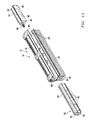
- FIG. 2 is a perspective, exploded view of the motorizable shade system of the present invention according to one embodiment
- FIG. 3 is a top view of the invention of FIG. 2 with part of the header and the header cover removed for clarity showing the motor assembly removed from the header system;
- FIG. 4 is a front view of the invention of FIG. 2 with part of the header and the header cover removed for clarity showing the motor assembly within the header system;
- FIG. 5 is a perspective view of the invention of FIG. 2 with part of the header and the header cover removed for clarity and showing the power contacts of the motor assembly;
- FIG. 6 is a bottom, partial perspective view showing the motor assembly and the positive and negative voltage carriers and an insulator
- FIG. 7 is a side end view of the invention of FIG. 2 ;
- FIG. 8 is a back view of the invention of FIG. 2 with some of the header removed for clarity;
- FIG. 9 is a partial perspective view with some of the header cut away for clarity showing the motor assembly being added to the invention.
- FIG. 10 is a front view of the invention of FIG. 9 ;
- FIG. 11 is a partial exploded view of the invention of FIG. 2 showing the motor assembly with its cover removed;
- FIG. 12 is a perspective partial cut away view of the invention of FIG. 2 showing one embodiment of the electrical connectors on the motor assembly and power system;
- FIG. 13 is a view of the invention as shown in FIG. 12 with the electrical connectors connected with each other;
- FIG. 14 is an exploded perspective view of the motorizable shade system of the present invention according to another embodiment
- FIG. 15 is an enlarged perspective view of the left side of the invention of FIG. 14 showing the batteries can be inserted from either end of the header system;
- FIG. 16 is an enlarged perspective view of the right side of FIG. 14 ;
- FIG. 17 is an end view of the invention with end cap and front cover removed
- FIG. 18 is an opposite perspective partial section view showing the motor assembly being inserted within the header
- FIG. 19 is a front section view taken along lines 19 - 19 in FIG. 18 ;
- FIG. 20 is an enlarged view of the right hand side of FIG. 19 .
- FIG. 1 is an illustration of what a typical shade system looks like from the outside, both the prior art and the present invention. That is, FIG. 1 shows a header system 12 that includes a header 14 and a front header cover 16 . Typically, header 12 is C-shaped and includes end caps 18 . In combination, header 14 , header cover 16 and end caps 18 completely enclose and hide from view whatever is inside of the header system 12 .
- FIG. 1 also illustrates a shade 20 .
- shade 20 is shown as a cellular shade. It is understood that any and all types of shades now known, such as roman shades, pleated shades, Venetian blind shades, or any shades hereafter developed are included in the term shade.
- FIG. 1 shows operational cord 21 .
- Operational cord 21 functions to raise and lower and tilt shade 20 forward or backward, all as is known in the art.
- the motorizable shade system 10 of the present invention includes a header system 12 , which includes a header 14 and may or may not include a header cover 16 . It can be clearly seen in this figure that, again as is typical, header 14 is C-shaped and includes a top 22 , a back 24 and a bottom 26 . End caps 18 are also shown.
- FIG. 2 also shows positive voltage carrier 28 and negative voltage carrier
- FIGS. 14-20 illustrate, among other things, the embodiment where the electrical voltage carriers are in the back 24 and the bottom 26 of header 14 , for example only.
- FIG. 2 shows both electrical conductive legs formed into and made a part of the bottom 26 of header 14 .
- the terms “formed into” and “made a part of” are used to define a structure that is an “integral” structure such that header system 12 itself is the positive voltage carrier 28 and the negative voltage carrier 30 .
- the term “voltage carrier” is used to describe a device that transmits current such as an exposed metal wire. Copper wire for example, but not by way of limitation, may be formed into a thin sheet and formed into the surface of the header system. The entire thin sheet then becomes an electrical carrier capable of transmitting current.
- the voltage carriers are integral to the header system 12 and are present in the manual, non-motorized, version of the invention. Their presence, along with other features of the invention as will be described hereafter, enable the manual shade to be quickly and easily made into a motorized shade without need for adding extraneous and obstructive wires and the like.
- Insulator 32 is also illustrated. Insulator 32 is any insulator now known or hereafter developed for electrically insulating positive voltage carrier 28 from negative voltage carrier 30 .
- FIG. 2 also shows motor assembly 34 , spool housing(s) 36 , battery housing 38 , batteries 40 , and counter balance 42 .
- Battery housing 38 and batteries 40 make up the power system 39 of the present invention.
- Power system 39 includes a power attachment connection 41 as will be described more fully with regard to FIG. 6 .
- FIG. 3 shows the motor assembly 34 removed from the header system 12 and illustrates the drive adaptor 44 which is part of motor assembly 34 .
- Drive adaptor 44 is conformed so as to connect with drive shaft 46 which is connected with the cord spool 48 (not shown but shown in FIGS. 8 and 9 ).
- FIG. 4 shows motor assembly 34 inserted within header system 12 and with drive adaptor 44 connected with drive shaft 46 such that upon operation of the motor assembly 34 , drive adaptor 44 turns drive shaft 46 and that turns cord spool 48 .
- FIG. 5 this partially exploded perspective view shows an important element of motor assembly 34 , first contact 50 and second contact 52 . These contacts provide the connection between the motor assembly 34 and the positive voltage carrier 28 and the negative voltage carrier 30 , as will be discussed more fully hereafter.
- suspension cord(s) 54 There are two illustrated but only one or many more may be needed depending on the size of shade 20 (not shown).
- Suspension cord(s) 54 are connected with the cord spool 48 on one end and with the shade 20 (not shown, see FIG. 8 ) on the other.
- suspension cord 54 is the cord from which the shade 20 is suspended. As the shade 20 is raised, suspension cord 54 is rolled up on cord spool 48 and as the shade 20 is lowered, suspension cord 54 is unwound from cord spool 48 .
- other means and methods for taking up and releasing suspension cord 54 as the shade 20 is raised and lowered are included within the scope of this invention.
- FIG. 6 shows first contact 50 and second contact 52 as they are connected to the motor assembly 34 .
- first contact 50 comes into contact with and makes an electrical connection with positive voltage carrier 28
- second contact 52 comes into contact with and makes an electrical connection with negative voltage carrier 30 when, and only when the user desires to “motorize” the manual shade system 10 .
- motor assembly 34 is inserted within header system 12 the electrical connections are made.
- first contact 50 and second contact 52 are “biased springs” that resist compression and thus maintain tight contact when compressed. This compression is accomplished, for example only and not by way of limitation, by the use of the leaf spring contacts, 50 and 52 , in combination with an integral header attachment connection 56 in the header system 12 and a motor assembly attachment connection 58 in the motor assembly 34 .
- integral header attachment connection 56 in the header system 12 consists of an overhanging lip 60 and motor assembly attachment connection 58 in the motor assembly 34 consists of an extended edge 62 .
- Extended edge 62 is captured within overhanging lip 60 as motor assembly 34 is inserted into header system 12 .
- This keeps motor assembly 34 securely connected with header assembly 12 such that biased spring connectors, first contact 50 and second contact 52 , are compressed as the motor assembly 34 is inserted into the header system 12 and thus kept pressed tightly against positive voltage carrier 28 and negative voltage carrier 30 .
- power system 39 is easily and securely connected with header system 12 by means of power attachment connection 41 in the form of extended edge 62 (See FIG. 2 ).
- FIGS. 14-20 illustrate another form of integral header attachment connection 56 and motor assembly and power attachment connections 58 and 41 , for example only, as will be described more fully hereafter.
- FIG. 7 a side end view of the invention shows header system 12 with the end cap 18 removed.
- Motor assembly 34 and power system 39 are held in place by the combination of integral header attachment connection 56 and motor assembly attachment connection 58 (and power attachment connection 41 hidden behind motor assembly 34 and not shown) thus ensuring secure and continuous contacts with the voltage carriers, 28 and 30 .
- this header attachment connection is preformed and integral to the manually operable shade of the present invention. It is in place, in other words, and available to safely and simply convert a manual shade to a motorized shade, or vice versa, when desired.
- FIG. 7 also shows suspension cord 54 connected with shade 20 at the bottom of shade 20 .
- an “end bar” 64 is provided at the bottom of a shade system to add rigidity and weight to the bottom of shade 20 .
- Other means and methods are, of course, known.
- FIG. 8 a perspective, partial cut away view, from behind the motorizable shade system 10 is presented.
- the top 22 and back 24 of header 14 have been removed for clarity.
- cord spools 48 are shown with suspension cords 54 connected with them and partially wound upon them.
- shaft supports 64 attached to the back of battery housing 38 , when in place within the header system 12 , for supporting the drive shaft(s) 46 of the cord spool(s) 48 .
- FIG. 8 shows a motorizable shade system 10 which the user has converted into a motorized shade system by the addition of the power system 39 in the form of battery housing 38 which makes electrical contact with one or the other of the positive voltage carrier 28 or the negative voltage carrier 30 .
- Batteries 40 provide the power to the carrier that is transmitted to the motor assembly 34 which enables a user to mechanically operate the previously manual shade system 10 . It is contemplated that battery housing 38 may be part of the manual shade system and then the only need is to add batteries 40 to complete the required power system 39 to power the circuit.
- FIG. 8 also shows counter balance 42 .
- the useful features of a counter balance are known in the art and one may or may not be included in the motorizable shade system 10 of the present invention. If present, obviously, drive shaft 46 is connected with counter balance 42 .
- FIGS. 9 and 10 these partial cut away views show motor assembly 34 inserted partially within header system 14 . They clearly show drive adaptor 44 and the exposed end of drive shaft 46 . When connected, again, movement of the drive adaptor 44 results in movement of drive shaft 46 .
- FIG. 9 also shows, again, positive voltage carrier 28 and negative voltage carrier 30 as part of the bottom 26 of header 14 with insulator 32 in between them. Again, this orientation is for example only and not by way of limitation. Another embodiment, for example only, is as illustrated hereafter in FIGS. 14-20 .
- motor assembly 34 includes a motor assembly housing 68 that is formed from the combination of a front housing 70 and a back housing 72 .
- motor 74 Within the motor assembly housing 68 are found motor 74 , an encoder 76 , a control board 78 and the portion of drive adaptor 44 connected within the motor assembly housing 68 to the motor 74 .
- antenna 80 and a timer 82 are also shown.
- this combination of elements is illustrative and more or fewer elements may be appropriate according to the needs of the user.
- encoder 76 when present, tracks the location of shade 20 relative to header system 12 and the lowest position of the end bar 64 .
- the shade 20 may be mechanically manipulated within those limits by means of control board 78 .
- Many manipulations are anticipated but a useful manipulation is the tracking of the time threshold for movement of the shade 20 with timer 82 and the detection of this time threshold by the control board 78 . For example, when the batteries 40 are fully charged the raising and/or lowering of the shade 20 takes a certain amount of time that is noted. Thereafter, as the batteries 40 discharge the time increases.
- control board 78 activates the shade 20 one last time and raises it up to the header system 12 leaving the shade 20 in a fully open position (See FIG. 14 for example) and signaling thereby the need to replace the batteries 40 .
- Many other manipulations are possible as well, of course.
- Antenna 80 is capable of receiving RF signals from a remote sending device (not shown) for the hands free operation of the motorizable shade system 10 of the present invention once it is in fact motorized.
- FIGS. 12 and 13 show motor assembly electrical connector 35 and power system electrical connector 43 . While any system that enables the connection of the motor assembly 34 with the power system 39 simply by inserting the two elements into header system 12 is included within the scope of the invention, FIGS. 12 and 13 show a preferred embodiment.
- motor assembly electrical connector 35 is shown in FIG. 12 connected with motor assembly 34 and extending some distance away from the motor assembly housing 68 . As motor assembly 34 is inserted within header 14 , motor assembly electrical connector 35 is brought closer and closer to power system electrical connector 43 .
- Power system electrical connector 43 is connected with power system 39 and extends some variable distance away from power system 39 .
- FIG. 13 shows the connection of motor assembly electrical connector 35 and power system electrical connector 43 .
- the connection is long enough between the two elements to bridge the length of spool housing 36 .
- electrical connectors 35 and 43 may be made in any connectable manner as in the plug and plug receptor manner illustrated. Just as obviously, electrical connectors may be any length deemed needed and useful.
- FIG. 14 another attachment connection system is described in which the motor assembly 34 and the power system 39 include slots 84 and the header 14 includes integral protrusion 86 .
- Integral protrusions 86 run the length of the header 14 on, preferably, both the inside of the top 22 and bottom 26 of header 14 .
- motor assembly 34 and power system 39 battery housing 38 specifically, include slots 84 along the length of both of the exterior surfaces of each as illustrated. In this manner, motor assembly 34 and power system 39 may be positioned anywhere along the integral protrusions 86 .
- this illustrates another embodiment of the required integral header attachment connection 56 and the motor assembly attachment connection 58 and the power attachment connection 41 as described above.
- FIG. 14 also shows another element of the invention in the form of biased leads 88 in motor assembly 34 which co-operate with recesses 90 in header 14 to hold motor assembly 34 in place when biased leads 88 expand into and are captured by recesses 90 .
- FIG. 15 provides a detailed, close up view of the elements of FIG. 14 on the left side of FIG. 14 and FIG. 16 provides a detailed, close up view of the elements of FIG. 14 on the rights side of FIG. 14 .
- FIG. 17 another embodiment of the invention is illustrated.
- two separate electrical carriers 92 and 94 are created in header system 12 .
- the top 22 of header 14 is connected with the back 24 such as by adhesive 96 , for example only.
- FIG. 18 is an opposite perspective, partial cut away view showing the motorizable shade system 10 of the present invention either transforming from a manual shade, with motor assembly 34 and power system 39 being added or being transformed to a manually operable shade system with these elements being removed.
- FIG. 19 is a section view taken along lines 19 - 19 in FIG. 18 and FIG. 20 is an enlarged view of the right side of FIG. 1 .
Abstract
Description
Claims (17)
Priority Applications (9)
| Application Number | Priority Date | Filing Date | Title |
|---|---|---|---|
| US12/925,269 US8820388B2 (en) | 2010-10-18 | 2010-10-18 | Motorizable shade system and method |
| US12/931,328 US8939190B2 (en) | 2010-10-18 | 2011-01-29 | Motorizable tilt shade system and method |
| AU2011318560A AU2011318560B2 (en) | 2010-10-18 | 2011-10-06 | Motorizable shade system and method |
| JP2013533839A JP5990756B2 (en) | 2010-10-18 | 2011-10-06 | Motorized sunshade apparatus and method |
| CA2815036A CA2815036C (en) | 2010-10-18 | 2011-10-06 | Motorizable shade system and method |
| PCT/US2011/001723 WO2012054070A1 (en) | 2010-10-18 | 2011-10-06 | Motorizable shade system and method |
| EP11834747.5A EP2630314A4 (en) | 2010-10-18 | 2011-10-06 | Motorizable shade system and method |
| CN201180059384.9A CN103261546B (en) | 2010-10-18 | 2011-10-06 | Mechanizablely block system and method |
| US13/908,612 US9091115B2 (en) | 2010-10-18 | 2013-06-03 | Motorizable tilt shade system and method |
Applications Claiming Priority (1)
| Application Number | Priority Date | Filing Date | Title |
|---|---|---|---|
| US12/925,269 US8820388B2 (en) | 2010-10-18 | 2010-10-18 | Motorizable shade system and method |
Related Child Applications (1)
| Application Number | Title | Priority Date | Filing Date |
|---|---|---|---|
| US12/931,328 Continuation-In-Part US8939190B2 (en) | 2010-10-18 | 2011-01-29 | Motorizable tilt shade system and method |
Publications (2)
| Publication Number | Publication Date |
|---|---|
| US20120090797A1 US20120090797A1 (en) | 2012-04-19 |
| US8820388B2 true US8820388B2 (en) | 2014-09-02 |
Family
ID=45933083
Family Applications (1)
| Application Number | Title | Priority Date | Filing Date |
|---|---|---|---|
| US12/925,269 Expired - Fee Related US8820388B2 (en) | 2010-10-18 | 2010-10-18 | Motorizable shade system and method |
Country Status (7)
| Country | Link |
|---|---|
| US (1) | US8820388B2 (en) |
| EP (1) | EP2630314A4 (en) |
| JP (1) | JP5990756B2 (en) |
| CN (1) | CN103261546B (en) |
| AU (1) | AU2011318560B2 (en) |
| CA (1) | CA2815036C (en) |
| WO (1) | WO2012054070A1 (en) |
Cited By (17)
| Publication number | Priority date | Publication date | Assignee | Title |
|---|---|---|---|---|
| US20140231032A1 (en) * | 2013-02-15 | 2014-08-21 | Lutron Electronics Co., Inc. | Battery-powered roller shade system |
| US20160108665A1 (en) * | 2011-03-11 | 2016-04-21 | Lutron Electronics Co., Inc. | Battery-powered motorized window treatment having a service position |
| US20160201389A1 (en) * | 2013-04-17 | 2016-07-14 | Qmotion Incorporated | System and Method for Manual and Motorized Manipulation of an Architectural Covering |
| US9487998B1 (en) * | 2015-10-13 | 2016-11-08 | Danny Agudelo | Window blinds with solar panels |
| US20170067286A1 (en) * | 2014-04-08 | 2017-03-09 | David R. Hall | Motorized Gearbox Assembly with Through-Channel Design |
| US9702189B2 (en) * | 2015-10-01 | 2017-07-11 | Calendar Enterprises Co., Ltd. | Energy saving apparatus for electric roller shutter |
| US20180030781A1 (en) * | 2016-07-27 | 2018-02-01 | David R. Hall | Solar-Powered Window Covering |
| US9982482B2 (en) | 2011-03-11 | 2018-05-29 | Lutron Electronics Co., Inc. | Battery-powered motorized window treatment having a service position |
| US10392860B2 (en) * | 2015-03-17 | 2019-08-27 | Eric Barnett | Systems and methods for controlling the blinds |
| US11234549B2 (en) | 2018-01-26 | 2022-02-01 | Current Products Corp. | Grommet drapery system |
| US20220162906A1 (en) * | 2020-11-24 | 2022-05-26 | Hunter Douglas Inc. | Stackable coverings with overpowered lift systems and related systems with hold-down brackets |
| USD961526S1 (en) * | 2021-03-25 | 2022-08-23 | Baoguo Tan | Wireless remote control for curtains |
| US11459821B2 (en) * | 2019-02-05 | 2022-10-04 | Hunter Douglas Inc. | Headrail for an architectural-structure covering |
| US11578531B2 (en) * | 2013-04-15 | 2023-02-14 | Lutron Technology Company Llc | Integrated accessible battery compartment for motorized window treatment |
| US20230124677A1 (en) * | 2020-04-14 | 2023-04-20 | Somfy Activites Sa | Screening device |
| US11744393B2 (en) | 2018-01-26 | 2023-09-05 | Current Products Corp. | Tabbed drapery system |
| US20230313606A1 (en) * | 2022-03-30 | 2023-10-05 | Ching Feng Home Fashions Co., Ltd. | Wireless electrically-controlled electric curtain |
Families Citing this family (23)
| Publication number | Priority date | Publication date | Assignee | Title |
|---|---|---|---|---|
| US8575872B2 (en) | 2010-02-23 | 2013-11-05 | Homerun Holdings Corporation | High efficiency roller shade and method for setting artificial stops |
| US9249623B2 (en) | 2010-02-23 | 2016-02-02 | Qmotion Incorporated | Low-power architectural covering |
| US9194179B2 (en) | 2010-02-23 | 2015-11-24 | Qmotion Incorporated | Motorized shade with the transmission wire passing through the support shaft |
| US8659246B2 (en) | 2010-02-23 | 2014-02-25 | Homerun Holdings Corporation | High efficiency roller shade |
| US8807196B2 (en) * | 2010-05-04 | 2014-08-19 | Qmotion Incorporated | Modular anti-reversible power spring apparatus and method |
| US8939190B2 (en) * | 2010-10-18 | 2015-01-27 | QMotion Limited | Motorizable tilt shade system and method |
| US8820388B2 (en) * | 2010-10-18 | 2014-09-02 | Qmotion Incorporated | Motorizable shade system and method |
| US9091115B2 (en) | 2010-10-18 | 2015-07-28 | Qmotion Incorporated | Motorizable tilt shade system and method |
| US9587431B2 (en) | 2013-03-15 | 2017-03-07 | Jackson Global Pte. Ltd. | Motorized window covering assembly |
| WO2013167972A2 (en) * | 2012-05-08 | 2013-11-14 | Jackson Global Pte.Ltd. | Motorized window covering assembly |
| CN105722438B (en) * | 2013-09-12 | 2020-04-14 | 立川窗饰工业株式会社 | Solar radiation shielding device |
| GB201405125D0 (en) * | 2014-03-21 | 2014-05-07 | Louver Lite Ltd | Window blind control apparatus |
| FR3027336B1 (en) * | 2014-10-20 | 2019-08-30 | Somfy Sas | RANGE OF MOTORIZED DRIVING DEVICES FOR OCCULT SCREENS |
| US10094169B2 (en) | 2014-11-01 | 2018-10-09 | Lutron Electronics Co., Inc. | Interlocking pivotable fascia for motorized window treatment |
| CA2870983A1 (en) | 2014-11-06 | 2016-05-06 | Etapa Window Fashions Inc | Motor retrofitted on roll-up blind cords |
| US10863846B2 (en) | 2015-10-02 | 2020-12-15 | Axis Labs Inc. | External motor drive system for window covering system with continuous cord loop |
| CN108463605B (en) | 2015-10-02 | 2019-11-08 | 艾西斯实验有限公司 | External electric motor drive system for the window covering system with continuous becket bridle |
| US11002071B2 (en) * | 2018-03-29 | 2021-05-11 | Crestron Electronics, Inc. | Architectural roller shade housing with adjustable battery compartment |
| US11421473B2 (en) * | 2018-03-29 | 2022-08-23 | Crestron Electronics, Inc. | Architectural roller shade housing with adjustable battery compartment |
| MX2022014569A (en) | 2020-05-22 | 2023-05-16 | Lutron Tech Co Llc | Battery-operated window treatment. |
| CN214330481U (en) * | 2021-03-18 | 2021-10-01 | 宁波森瑞机电技术有限公司 | Intelligent sunshade curtain with replaceable battery |
| US11840886B2 (en) | 2021-05-12 | 2023-12-12 | Ryse Inc. | External motor drive system adjusting for creep in window covering system with continuous cord loop |
| US20230151682A1 (en) * | 2021-11-16 | 2023-05-18 | Lutron Technology Company Llc | Motorized window treatment |
Citations (43)
| Publication number | Priority date | Publication date | Assignee | Title |
|---|---|---|---|---|
| US4096903A (en) | 1974-07-05 | 1978-06-27 | Ringle Iii John | Power drive for a venetian blind |
| US4554762A (en) | 1983-03-07 | 1985-11-26 | Anderson Robert W | Electrically powered sun blind |
| US4618804A (en) | 1984-06-28 | 1986-10-21 | Kanematsu-Gosho, Ltd. | Remote control apparatus for opening and shutting a blind |
| US4706726A (en) | 1985-01-10 | 1987-11-17 | V. Kann Rasmussen Industri A/S | Electric control of venetian blind |
| US5038087A (en) * | 1989-01-20 | 1991-08-06 | Ambient Energy Design Opm | Apparatus for controlling window blinds and awnings |
| US5391967A (en) * | 1993-06-11 | 1995-02-21 | Harmonic Design Inc. | Head rail-mounted mini-blind actuator |
| US5413161A (en) | 1993-09-09 | 1995-05-09 | Corazzini; Warren | Solar powered window shade |
| US5444339A (en) * | 1993-06-11 | 1995-08-22 | Harmonic Design, Inc. | Mini-blind actuator |
| US5495153A (en) * | 1993-06-11 | 1996-02-27 | Harmonic Design, Inc. | Head rail-mounted mini-blind actuator for vertical blinds and pleated shades |
| US5517094A (en) * | 1993-07-20 | 1996-05-14 | Harmonic Design, Inc. | Head rail-mounted mini-blind actuator |
| US5531257A (en) | 1994-04-06 | 1996-07-02 | Newell Operating Company | Cordless, balanced window covering |
| US5698958A (en) * | 1993-06-11 | 1997-12-16 | Harmonic Design, Inc. | Head rail-mounted actuator for window coverings |
| US5729103A (en) * | 1993-06-11 | 1998-03-17 | Harmonic Design, Inc. | Head rail-mounted actuator for window coverings |
| US5760558A (en) * | 1995-07-24 | 1998-06-02 | Popat; Pradeep P. | Solar-powered, wireless, retrofittable, automatic controller for venetian blinds and similar window converings |
| US5793174A (en) * | 1996-09-06 | 1998-08-11 | Hunter Douglas Inc. | Electrically powered window covering assembly |
| US6003584A (en) * | 1996-02-08 | 1999-12-21 | Weinreich; Steve | Mechanism for constant balance |
| US6060852A (en) * | 1993-06-11 | 2000-05-09 | Harmonic Design, Inc. | Head rail-mounted actuator for window covering |
| US6062290A (en) * | 1998-02-27 | 2000-05-16 | Harmonic Design, Inc. | Photocell mounting apparatus for vertical blinds |
| US6116320A (en) * | 1999-01-09 | 2000-09-12 | Barker Holding Company, Llc | Automatic window shade system |
| US6338377B1 (en) * | 2000-06-05 | 2002-01-15 | Harmonic Design, Incorporated | Skylight assembly with head rail-mounted actuator |
| US20020027184A1 (en) * | 1998-06-22 | 2002-03-07 | Kovach Joseph E. | Remote control operating system and support structure for a retractable covering for an architectural opening |
| US6369530B2 (en) * | 1996-09-06 | 2002-04-09 | Hunter Douglas Inc. | Battery-powered wireless remote-control motorized window covering assembly having controller components |
| US6371192B1 (en) * | 1999-01-11 | 2002-04-16 | Hunter Douglas Inc. | Headrail, including a trap door for accessing batteries for powered coverings for architectual openings |
| US6382294B1 (en) * | 1999-01-11 | 2002-05-07 | Hunter Douglas Inc. | System for holding batteries in a headrail for powered coverings for architectural openings |
| US6446693B1 (en) | 1999-01-11 | 2002-09-10 | Hunter Douglas Inc. | Headrail and control system for powered coverings for architectural openings |
| US6516858B1 (en) * | 1999-01-11 | 2003-02-11 | Hunter Douglas | Headrail including a detachable battery holder for powered coverings for architectural openings |
| US6536503B1 (en) | 1999-03-23 | 2003-03-25 | Hunter Douglas Inc. | Modular transport system for coverings for architectural openings |
| US20030145957A1 (en) * | 2002-02-01 | 2003-08-07 | Domel Douglas R. | Low power, high resolution position encoder for motorized window covering |
| US20030145958A1 (en) * | 2002-02-01 | 2003-08-07 | Domel Douglas R. | Low power, high resolution position encoder for motorized window covering |
| US6655441B2 (en) | 2002-03-07 | 2003-12-02 | Industrial Technology Research Institute | Friction transmission mechanism for a motor-driven blind |
| US6708750B2 (en) * | 2000-02-24 | 2004-03-23 | Techno Patenten B.V. | Control and motorization system |
| US6795226B2 (en) | 2000-05-04 | 2004-09-21 | Schott Corporation | Chromogenic glazing |
| US6867565B2 (en) | 2002-05-13 | 2005-03-15 | Somfy | Process for learning the limits of travel of a roller blind actuator |
| US6957683B2 (en) | 1997-11-04 | 2005-10-25 | Toti Andrew J | Spring drive system and window cover |
| US7129657B2 (en) * | 2004-06-07 | 2006-10-31 | Somfy Sas | Single track brush-based position encoder for rotating shaft |
| US7389806B2 (en) | 2005-02-24 | 2008-06-24 | Lawrence Kates | Motorized window shade system |
| US20080230189A1 (en) * | 2007-03-20 | 2008-09-25 | Newell Window Furnishings, Inc. | Flexible window covering |
| US20100269988A1 (en) * | 2008-12-04 | 2010-10-28 | Willis Jay Mullet | Counterbalanced motorized shade roll system and method |
| US7857030B2 (en) * | 2007-07-10 | 2010-12-28 | Li-Ming Cheng | Window covering switchable to manual operation and electrical operation and a clutch thereof |
| US20120031567A1 (en) * | 2006-01-20 | 2012-02-09 | Albany International Corp. | Wireless communication system for a roll-up door |
| US20120031571A1 (en) * | 2010-02-23 | 2012-02-09 | Homerun Holdings Corporation | High Efficiency Roller Shade |
| US20120090797A1 (en) * | 2010-10-18 | 2012-04-19 | Willis Jay Mullet | Motorizable shade system and method |
| US20120111509A1 (en) * | 2010-10-18 | 2012-05-10 | Willis Jay Mullet | Motorizable tilt shade system and method |
Family Cites Families (11)
| Publication number | Priority date | Publication date | Assignee | Title |
|---|---|---|---|---|
| JP2571507B2 (en) * | 1992-12-25 | 1997-01-16 | ネポン株式会社 | Skylight opening / closing device control unit for greenhouse for greenhouse and its operating method |
| JPH071285U (en) * | 1993-06-07 | 1995-01-10 | トーソー株式会社 | Mount for electrical components for electric blinds |
| US5372173A (en) * | 1993-07-16 | 1994-12-13 | Horner; William P. | Window having motorized shades |
| CA2270006C (en) * | 1999-04-22 | 2001-09-04 | Stores All-Teck P.T.B. Inc./All-Teck Blinds P.T.B. Inc. | Head-rail end adaptor for window blinds |
| WO2002068786A1 (en) * | 2001-02-28 | 2002-09-06 | Vkr Holding A/S | Screening device and drive means for the screening device and method of manual operating the screening device and a mounting for the screening device |
| EP1371808A1 (en) * | 2002-06-10 | 2003-12-17 | Nien Made Enterprise Co Ltd | Battery-operated electric blind |
| CN2616652Y (en) * | 2003-04-08 | 2004-05-19 | 邹立伟 | Automatic rolling device for curtain |
| US20070107854A1 (en) * | 2005-11-16 | 2007-05-17 | Hunter Douglas Inc. | Operating system for collapsible covering for architectural openings |
| US7723939B2 (en) * | 2006-05-23 | 2010-05-25 | Lutron Electronics Co., Inc. | Radio-frequency controlled motorized roller shade |
| US20080121353A1 (en) * | 2006-11-16 | 2008-05-29 | Detmer Brandon J | Manual roller shade having clutch mechanism, chain guide and universal mounting |
| US20090308543A1 (en) * | 2008-06-13 | 2009-12-17 | Lawrence Kates | Motorized window shade system and mount |
-
2010
- 2010-10-18 US US12/925,269 patent/US8820388B2/en not_active Expired - Fee Related
-
2011
- 2011-10-06 EP EP11834747.5A patent/EP2630314A4/en not_active Withdrawn
- 2011-10-06 CN CN201180059384.9A patent/CN103261546B/en not_active Expired - Fee Related
- 2011-10-06 WO PCT/US2011/001723 patent/WO2012054070A1/en active Application Filing
- 2011-10-06 AU AU2011318560A patent/AU2011318560B2/en not_active Ceased
- 2011-10-06 CA CA2815036A patent/CA2815036C/en not_active Expired - Fee Related
- 2011-10-06 JP JP2013533839A patent/JP5990756B2/en not_active Expired - Fee Related
Patent Citations (55)
| Publication number | Priority date | Publication date | Assignee | Title |
|---|---|---|---|---|
| US4096903A (en) | 1974-07-05 | 1978-06-27 | Ringle Iii John | Power drive for a venetian blind |
| US4554762A (en) | 1983-03-07 | 1985-11-26 | Anderson Robert W | Electrically powered sun blind |
| US4618804A (en) | 1984-06-28 | 1986-10-21 | Kanematsu-Gosho, Ltd. | Remote control apparatus for opening and shutting a blind |
| US4706726A (en) | 1985-01-10 | 1987-11-17 | V. Kann Rasmussen Industri A/S | Electric control of venetian blind |
| US5038087A (en) * | 1989-01-20 | 1991-08-06 | Ambient Energy Design Opm | Apparatus for controlling window blinds and awnings |
| US5495153A (en) * | 1993-06-11 | 1996-02-27 | Harmonic Design, Inc. | Head rail-mounted mini-blind actuator for vertical blinds and pleated shades |
| US6433498B1 (en) * | 1993-06-11 | 2002-08-13 | Harmonic Design, Inc. | Head rail-mounted actuator for window coverings |
| US5444339A (en) * | 1993-06-11 | 1995-08-22 | Harmonic Design, Inc. | Mini-blind actuator |
| US5907227A (en) * | 1993-06-11 | 1999-05-25 | Harmonic Design, Inc. | Head rail-mounted actuator for window coverings |
| US5391967A (en) * | 1993-06-11 | 1995-02-21 | Harmonic Design Inc. | Head rail-mounted mini-blind actuator |
| US5698958A (en) * | 1993-06-11 | 1997-12-16 | Harmonic Design, Inc. | Head rail-mounted actuator for window coverings |
| US5714855A (en) * | 1993-06-11 | 1998-02-03 | Harmonic Design, Inc. | Head rail-mounted actuator for window coverings |
| US5729103A (en) * | 1993-06-11 | 1998-03-17 | Harmonic Design, Inc. | Head rail-mounted actuator for window coverings |
| US6850017B1 (en) * | 1993-06-11 | 2005-02-01 | Harmonic Design, Inc. | Head rail-mounted actuator for window coverings |
| US6060852A (en) * | 1993-06-11 | 2000-05-09 | Harmonic Design, Inc. | Head rail-mounted actuator for window covering |
| US5517094A (en) * | 1993-07-20 | 1996-05-14 | Harmonic Design, Inc. | Head rail-mounted mini-blind actuator |
| US5413161A (en) | 1993-09-09 | 1995-05-09 | Corazzini; Warren | Solar powered window shade |
| US5531257A (en) | 1994-04-06 | 1996-07-02 | Newell Operating Company | Cordless, balanced window covering |
| US5760558A (en) * | 1995-07-24 | 1998-06-02 | Popat; Pradeep P. | Solar-powered, wireless, retrofittable, automatic controller for venetian blinds and similar window converings |
| US5883480A (en) * | 1995-11-15 | 1999-03-16 | Harmonic Desing, Inc. | Window covering with head rail-mounted actuator |
| US6003584A (en) * | 1996-02-08 | 1999-12-21 | Weinreich; Steve | Mechanism for constant balance |
| US5990646A (en) * | 1996-09-06 | 1999-11-23 | Hunter Douglas Inc. | Remotely-controlled battery powered-window covering having power saving receiver |
| US5793174A (en) * | 1996-09-06 | 1998-08-11 | Hunter Douglas Inc. | Electrically powered window covering assembly |
| US6259218B1 (en) * | 1996-09-06 | 2001-07-10 | Hunter Douglas Inc. | Battery-powered wireless remote-control motorized window covering assembly having a microprocessor controller |
| US6369530B2 (en) * | 1996-09-06 | 2002-04-09 | Hunter Douglas Inc. | Battery-powered wireless remote-control motorized window covering assembly having controller components |
| US6957683B2 (en) | 1997-11-04 | 2005-10-25 | Toti Andrew J | Spring drive system and window cover |
| US6062290A (en) * | 1998-02-27 | 2000-05-16 | Harmonic Design, Inc. | Photocell mounting apparatus for vertical blinds |
| US20020027184A1 (en) * | 1998-06-22 | 2002-03-07 | Kovach Joseph E. | Remote control operating system and support structure for a retractable covering for an architectural opening |
| US7147029B2 (en) * | 1998-06-22 | 2006-12-12 | Hunter Douglas Inc. | Remote control operating system and support structure for a retractable covering for an architectural opening |
| US6116320A (en) * | 1999-01-09 | 2000-09-12 | Barker Holding Company, Llc | Automatic window shade system |
| US6736186B2 (en) * | 1999-01-11 | 2004-05-18 | Hunter Douglas Inc. | Headrail and control system for powered coverings for architectural openings |
| US6371192B1 (en) * | 1999-01-11 | 2002-04-16 | Hunter Douglas Inc. | Headrail, including a trap door for accessing batteries for powered coverings for architectual openings |
| US20020088561A1 (en) * | 1999-01-11 | 2002-07-11 | Anderson Richard N. | System for holding batteries in a headrail for powered coverings for architectural openings |
| US6533018B2 (en) * | 1999-01-11 | 2003-03-18 | Hunter Douglas Inc. | System for holding batteries in a headrail for powered coverings for architectural openings |
| US6446693B1 (en) | 1999-01-11 | 2002-09-10 | Hunter Douglas Inc. | Headrail and control system for powered coverings for architectural openings |
| US6516858B1 (en) * | 1999-01-11 | 2003-02-11 | Hunter Douglas | Headrail including a detachable battery holder for powered coverings for architectural openings |
| US6382294B1 (en) * | 1999-01-11 | 2002-05-07 | Hunter Douglas Inc. | System for holding batteries in a headrail for powered coverings for architectural openings |
| US6536503B1 (en) | 1999-03-23 | 2003-03-25 | Hunter Douglas Inc. | Modular transport system for coverings for architectural openings |
| US6708750B2 (en) * | 2000-02-24 | 2004-03-23 | Techno Patenten B.V. | Control and motorization system |
| US6795226B2 (en) | 2000-05-04 | 2004-09-21 | Schott Corporation | Chromogenic glazing |
| US6338377B1 (en) * | 2000-06-05 | 2002-01-15 | Harmonic Design, Incorporated | Skylight assembly with head rail-mounted actuator |
| US20030145957A1 (en) * | 2002-02-01 | 2003-08-07 | Domel Douglas R. | Low power, high resolution position encoder for motorized window covering |
| US20030145956A1 (en) * | 2002-02-01 | 2003-08-07 | Domel Douglas R. | Operating signal system and method for controlling a motorized window covering |
| US20030145958A1 (en) * | 2002-02-01 | 2003-08-07 | Domel Douglas R. | Low power, high resolution position encoder for motorized window covering |
| US6655441B2 (en) | 2002-03-07 | 2003-12-02 | Industrial Technology Research Institute | Friction transmission mechanism for a motor-driven blind |
| US6867565B2 (en) | 2002-05-13 | 2005-03-15 | Somfy | Process for learning the limits of travel of a roller blind actuator |
| US7129657B2 (en) * | 2004-06-07 | 2006-10-31 | Somfy Sas | Single track brush-based position encoder for rotating shaft |
| US7389806B2 (en) | 2005-02-24 | 2008-06-24 | Lawrence Kates | Motorized window shade system |
| US20120031567A1 (en) * | 2006-01-20 | 2012-02-09 | Albany International Corp. | Wireless communication system for a roll-up door |
| US20080230189A1 (en) * | 2007-03-20 | 2008-09-25 | Newell Window Furnishings, Inc. | Flexible window covering |
| US7857030B2 (en) * | 2007-07-10 | 2010-12-28 | Li-Ming Cheng | Window covering switchable to manual operation and electrical operation and a clutch thereof |
| US20100269988A1 (en) * | 2008-12-04 | 2010-10-28 | Willis Jay Mullet | Counterbalanced motorized shade roll system and method |
| US20120031571A1 (en) * | 2010-02-23 | 2012-02-09 | Homerun Holdings Corporation | High Efficiency Roller Shade |
| US20120090797A1 (en) * | 2010-10-18 | 2012-04-19 | Willis Jay Mullet | Motorizable shade system and method |
| US20120111509A1 (en) * | 2010-10-18 | 2012-05-10 | Willis Jay Mullet | Motorizable tilt shade system and method |
Cited By (26)
| Publication number | Priority date | Publication date | Assignee | Title |
|---|---|---|---|---|
| US11015387B2 (en) | 2011-03-11 | 2021-05-25 | Lutron Technology Company Llc | Battery-powered motorized window treatment having a service position |
| US20160108665A1 (en) * | 2011-03-11 | 2016-04-21 | Lutron Electronics Co., Inc. | Battery-powered motorized window treatment having a service position |
| US11680445B2 (en) | 2011-03-11 | 2023-06-20 | Lutron Technology Company Llc | Battery-powered motorized window treatment having a service position |
| US9982482B2 (en) | 2011-03-11 | 2018-05-29 | Lutron Electronics Co., Inc. | Battery-powered motorized window treatment having a service position |
| US10590700B2 (en) | 2011-03-11 | 2020-03-17 | Lutron Technology Company Llc | Battery-powered motorized window treatment having a service position |
| US9745796B2 (en) * | 2011-03-11 | 2017-08-29 | Lutron Electronics Co., Inc. | Battery-powered motorized window treatment having a service position |
| US9115537B2 (en) * | 2013-02-15 | 2015-08-25 | Lutron Electronics Co., Inc. | Battery-powered roller shade system |
| US20140231032A1 (en) * | 2013-02-15 | 2014-08-21 | Lutron Electronics Co., Inc. | Battery-powered roller shade system |
| US11578531B2 (en) * | 2013-04-15 | 2023-02-14 | Lutron Technology Company Llc | Integrated accessible battery compartment for motorized window treatment |
| US9670724B2 (en) * | 2013-04-17 | 2017-06-06 | The Watt Stopper, Inc. | System and method for manual and motorized manipulation of an architectural covering |
| US20160201389A1 (en) * | 2013-04-17 | 2016-07-14 | Qmotion Incorporated | System and Method for Manual and Motorized Manipulation of an Architectural Covering |
| US9869124B2 (en) * | 2014-04-08 | 2018-01-16 | David R. Hall | Motorized gearbox assembly with through-channel design |
| US20170067286A1 (en) * | 2014-04-08 | 2017-03-09 | David R. Hall | Motorized Gearbox Assembly with Through-Channel Design |
| US10392860B2 (en) * | 2015-03-17 | 2019-08-27 | Eric Barnett | Systems and methods for controlling the blinds |
| US9702189B2 (en) * | 2015-10-01 | 2017-07-11 | Calendar Enterprises Co., Ltd. | Energy saving apparatus for electric roller shutter |
| US9487998B1 (en) * | 2015-10-13 | 2016-11-08 | Danny Agudelo | Window blinds with solar panels |
| US10458179B2 (en) * | 2016-07-27 | 2019-10-29 | Hall Labs Llc | Solar-powered window covering |
| US20180030781A1 (en) * | 2016-07-27 | 2018-02-01 | David R. Hall | Solar-Powered Window Covering |
| US11234549B2 (en) | 2018-01-26 | 2022-02-01 | Current Products Corp. | Grommet drapery system |
| US11744393B2 (en) | 2018-01-26 | 2023-09-05 | Current Products Corp. | Tabbed drapery system |
| US11459821B2 (en) * | 2019-02-05 | 2022-10-04 | Hunter Douglas Inc. | Headrail for an architectural-structure covering |
| US20230124677A1 (en) * | 2020-04-14 | 2023-04-20 | Somfy Activites Sa | Screening device |
| US11713619B2 (en) * | 2020-04-14 | 2023-08-01 | Somfy Activites Sa | Screening device |
| US20220162906A1 (en) * | 2020-11-24 | 2022-05-26 | Hunter Douglas Inc. | Stackable coverings with overpowered lift systems and related systems with hold-down brackets |
| USD961526S1 (en) * | 2021-03-25 | 2022-08-23 | Baoguo Tan | Wireless remote control for curtains |
| US20230313606A1 (en) * | 2022-03-30 | 2023-10-05 | Ching Feng Home Fashions Co., Ltd. | Wireless electrically-controlled electric curtain |
Also Published As
| Publication number | Publication date |
|---|---|
| CN103261546A (en) | 2013-08-21 |
| CN103261546B (en) | 2016-02-03 |
| CA2815036C (en) | 2019-01-08 |
| EP2630314A1 (en) | 2013-08-28 |
| CA2815036A1 (en) | 2012-04-26 |
| JP2013539835A (en) | 2013-10-28 |
| WO2012054070A1 (en) | 2012-04-26 |
| EP2630314A4 (en) | 2017-08-16 |
| JP5990756B2 (en) | 2016-09-14 |
| AU2011318560A1 (en) | 2013-05-23 |
| US20120090797A1 (en) | 2012-04-19 |
| AU2011318560B2 (en) | 2017-04-20 |
Similar Documents
| Publication | Publication Date | Title |
|---|---|---|
| US8820388B2 (en) | Motorizable shade system and method | |
| US8939190B2 (en) | Motorizable tilt shade system and method | |
| US9091115B2 (en) | Motorizable tilt shade system and method | |
| US11680445B2 (en) | Battery-powered motorized window treatment having a service position | |
| JP4532901B2 (en) | Operator system and opening member including the operator system | |
| EP2683905B1 (en) | Battery-powered motorized window treatment having a service position | |
| US20130087296A1 (en) | Automatic releasable top down shade system and method | |
| WO2014043711A1 (en) | A drapery tube incorporating batteries within the drapery tube, with a stop for facilitating the loading and unloading of the batteries | |
| US20160130874A1 (en) | Motor drive system for window covering system with continuous cord loop | |
| US20050183833A1 (en) | Automated shutter control | |
| US10227822B2 (en) | Home-automation equipment for closure or solar protection and method for recharging a battery for such equipment | |
| WO2002041740A1 (en) | Solar powered motorized covering for an architectural opening | |
| US20230151682A1 (en) | Motorized window treatment | |
| US11713619B2 (en) | Screening device | |
| EP2700783B1 (en) | Magnetic mechanism for venetian blinds actuation positioned in between double glazing with the use of a small DC electric motor | |
| EP4095344A1 (en) | Control device for lighting elements to be mounted on a roll-up cover installation | |
| US20230279724A1 (en) | Battery-Powered Motorized Window Treatment Having a Service Position | |
| CZ18540U1 (en) | Device to operate and control of operation of black-out system driving mechanism |
Legal Events
| Date | Code | Title | Description |
|---|---|---|---|
| AS | Assignment |
Owner name: HOMERUN HOLDINGS CORP., FLORIDA Free format text: ASSIGNMENT OF ASSIGNORS INTEREST;ASSIGNORS:MULLET, WILLIS JAY;BRUNK, DARRIN W.;HAND, RICHARD SCOTT;AND OTHERS;SIGNING DATES FROM 20101005 TO 20101013;REEL/FRAME:025212/0473 |
|
| AS | Assignment |
Owner name: QMOTION INCORPORATED, FLORIDA Free format text: CHANGE OF NAME;ASSIGNOR:HOMERUN HOLDINGS CORPORATION;REEL/FRAME:032549/0330 Effective date: 20130429 |
|
| STCF | Information on status: patent grant |
Free format text: PATENTED CASE |
|
| AS | Assignment |
Owner name: THE WATT STOPPER, INC., CALIFORNIA Free format text: ASSIGNMENT OF ASSIGNORS INTEREST;ASSIGNOR:QMOTION INCORPORATED;REEL/FRAME:037608/0688 Effective date: 20151217 |
|
| FEPP | Fee payment procedure |
Free format text: ENTITY STATUS SET TO UNDISCOUNTED (ORIGINAL EVENT CODE: BIG.) |
|
| MAFP | Maintenance fee payment |
Free format text: PAYMENT OF MAINTENANCE FEE, 4TH YEAR, LARGE ENTITY (ORIGINAL EVENT CODE: M1551) Year of fee payment: 4 |
|
| FEPP | Fee payment procedure |
Free format text: MAINTENANCE FEE REMINDER MAILED (ORIGINAL EVENT CODE: REM.); ENTITY STATUS OF PATENT OWNER: LARGE ENTITY |
|
| LAPS | Lapse for failure to pay maintenance fees |
Free format text: PATENT EXPIRED FOR FAILURE TO PAY MAINTENANCE FEES (ORIGINAL EVENT CODE: EXP.); ENTITY STATUS OF PATENT OWNER: LARGE ENTITY |
|
| STCH | Information on status: patent discontinuation |
Free format text: PATENT EXPIRED DUE TO NONPAYMENT OF MAINTENANCE FEES UNDER 37 CFR 1.362 |
|
| FP | Lapsed due to failure to pay maintenance fee |
Effective date: 20220902 |