US8822819B2 - Server enclosure - Google Patents
Server enclosure Download PDFInfo
- Publication number
- US8822819B2 US8822819B2 US13/408,006 US201213408006A US8822819B2 US 8822819 B2 US8822819 B2 US 8822819B2 US 201213408006 A US201213408006 A US 201213408006A US 8822819 B2 US8822819 B2 US 8822819B2
- Authority
- US
- United States
- Prior art keywords
- panel
- securing
- server enclosure
- enclosure
- sidewall
- Prior art date
- Legal status (The legal status is an assumption and is not a legal conclusion. Google has not performed a legal analysis and makes no representation as to the accuracy of the status listed.)
- Expired - Fee Related, expires
Links
Images


Classifications
-
- H—ELECTRICITY
- H05—ELECTRIC TECHNIQUES NOT OTHERWISE PROVIDED FOR
- H05K—PRINTED CIRCUITS; CASINGS OR CONSTRUCTIONAL DETAILS OF ELECTRIC APPARATUS; MANUFACTURE OF ASSEMBLAGES OF ELECTRICAL COMPONENTS
- H05K5/00—Casings, cabinets or drawers for electric apparatus
-
- H—ELECTRICITY
- H05—ELECTRIC TECHNIQUES NOT OTHERWISE PROVIDED FOR
- H05K—PRINTED CIRCUITS; CASINGS OR CONSTRUCTIONAL DETAILS OF ELECTRIC APPARATUS; MANUFACTURE OF ASSEMBLAGES OF ELECTRICAL COMPONENTS
- H05K7/00—Constructional details common to different types of electric apparatus
- H05K7/14—Mounting supporting structure in casing or on frame or rack
- H05K7/1485—Servers; Data center rooms, e.g. 19-inch computer racks
- H05K7/1488—Cabinets therefor, e.g. chassis or racks or mechanical interfaces between blades and support structures
- H05K7/1489—Cabinets therefor, e.g. chassis or racks or mechanical interfaces between blades and support structures characterized by the mounting of blades therein, e.g. brackets, rails, trays
-
- G—PHYSICS
- G06—COMPUTING; CALCULATING OR COUNTING
- G06F—ELECTRIC DIGITAL DATA PROCESSING
- G06F1/00—Details not covered by groups G06F3/00 - G06F13/00 and G06F21/00
- G06F1/16—Constructional details or arrangements
Definitions
- the disclosure generally relates to a server enclosure.
- Many servers include an enclosure and a plurality of elements mounted in the enclosure.
- the enclosure includes a panel having a plurality of openings for receiving cables or guiding airflow.
- openings can weaken the panel, thereby affecting the structural integrity of the enclosure.
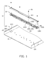
- FIG. 1 is an exploded, isometric view of an embodiment of a server enclosure.
- FIG. 2 is an isometric view of a loading member of the server enclosure of FIG. 1 .
- FIG. 3 is an assembled view of the server enclosure of FIG. 1 .
- one embodiment of a server enclosure includes an enclosure body 20 , a connecting member 30 , and a loading member 40 .
- the enclosure body 20 includes a bottom wall 21 and two sidewalls 22 extending perpendicularly from the bottom wall 21 .
- the two sidewalls 22 are parallel to each other.
- the bottom wall 21 defines a plurality of first mounting holes 211 .
- Each sidewall 22 includes two positioning posts 221 .
- Two first securing holes 223 are defined in each sidewall 22 .
- the connecting member 30 includes a top panel 31 and two mounting portions 33 extending from opposite edges of the top panel 31 .
- Each mounting portion 33 includes a resisting panel 331 extending perpendicularly from the top panel 31 , a securing portion 333 extending perpendicularly from the resisting panel 331 .
- the two resisting panels 331 are parallel to each other.
- the resisting panel 331 is substantially perpendicular to the bottom wall 21 .
- Each mounting portion 33 further includes two positioning portions 335 extending perpendicularly from opposite edges of each resisting panel 331 .
- a plurality of first screwing holes 311 is defined in the top panel 31 .
- a plurality of openings 3311 is defined in the resisting panel 331 .
- a plurality of second mounting holes 3331 is defined in the securing portion 333 corresponding to the first mounting holes 211 .
- a positioning hole 3351 is defined in the positioning portion 335 corresponding the positioning post 221 .
- the positioning portion 335 is substantially perpendicular to the securing portion 333 .
- the resisting panel 333 is substantially perpendicular to the sidewall 22 and the bottom wall 21 .
- the loading member 40 includes a bottom panel 41 substantially parallel to the top panel 31 and two connecting portions 43 extending from the bottom panel 41 .
- Each connecting portion 43 includes a connecting panel 431 extending substantially perpendicularly from the bottom panel 41 .
- the connecting panel 431 is substantially perpendicular to the sidewall 22 .
- the two connecting panels 431 are substantially parallel to each other.
- Each connecting portion 43 further includes two mounting tabs 433 extending from opposite edges of the connecting panel 41 .
- a plurality of second screwing holes 411 is defined in the bottom panel 41 .
- a second securing hole 4331 is defined in each mounting tab 433 corresponding to the first securing hole 223 .
- the mounting tab 433 is substantially parallel to the sidewalls 22 .
- the cross section of the loading member 40 taken along a plane substantially parallel to the sidewall 22 is U-shaped.
- the length of the connecting panel 431 is substantially equal to a distance between the two sidewalls 22 .
- the connecting member 30 is placed on the bottom wall 21 of the enclosure body 20 to enable the positioning posts 221 of the enclosure body 20 to pass through the positioning holes 3351 of the connecting member 30 .
- the second mounting holes 3331 of the connecting member 30 are aligned with the first mounting holes 211 of the bottom wall 21 .
- a plurality of screws (not shown) is screwed into the first mounting holes 3331 and the first mounting holes 211 to secure the connecting member 30 to the bottom wall 21 .
- the bottom panel 41 of the loading member 40 is placed on the top panel 31 of the connecting member 30 to enable the first screwing holes 311 to be aligned with the second screwing holes 411 of the loading member 40 .
- the second securing holes 4331 of the loading member 40 are aligned with the first securing holes 223 of the enclosure body 20 .
- a plurality of screws 70 is screwed into the second screwing holes 411 and the first screwing holes 311 to secure the loading member 40 and the connecting member 30 together.
- a plurality of fasteners (not shown) is fastened into the second securing holes 4331 and the first securing holes 223 to secure the loading member 40 to the enclosure body 20 .
- the loading member 40 is secured on the connecting member 30 .
- the loading member 40 is capable of protecting the connecting member 30 from being deformed when pressure is applied to the server enclosure 10 .
- the loading member 40 and the connecting member 30 are secured between the two sidewalls 22 , thereby protecting the enclosure body 20 from being deformed when pressure is applied to the enclosure body 20 .
Abstract
Description
Claims (18)
Applications Claiming Priority (3)
| Application Number | Priority Date | Filing Date | Title |
|---|---|---|---|
| CN2011101553624A CN102821577A (en) | 2011-06-10 | 2011-06-10 | Casing of electronic device |
| CN201110155362 | 2011-06-10 | ||
| CN201110155362.4 | 2011-06-10 |
Publications (2)
| Publication Number | Publication Date |
|---|---|
| US20120314357A1 US20120314357A1 (en) | 2012-12-13 |
| US8822819B2 true US8822819B2 (en) | 2014-09-02 |
Family
ID=47293015
Family Applications (1)
| Application Number | Title | Priority Date | Filing Date |
|---|---|---|---|
| US13/408,006 Expired - Fee Related US8822819B2 (en) | 2011-06-10 | 2012-02-29 | Server enclosure |
Country Status (3)
| Country | Link |
|---|---|
| US (1) | US8822819B2 (en) |
| CN (1) | CN102821577A (en) |
| TW (1) | TW201251562A (en) |
Families Citing this family (2)
| Publication number | Priority date | Publication date | Assignee | Title |
|---|---|---|---|---|
| US9974202B1 (en) * | 2016-10-26 | 2018-05-15 | International Business Machines Corporation | Electronic equipment divider assembly |
| US11635791B2 (en) * | 2020-08-28 | 2023-04-25 | Quanta Computer Inc. | System and method for assembling multiple housing rows for computer components |
Citations (11)
| Publication number | Priority date | Publication date | Assignee | Title |
|---|---|---|---|---|
| US5825962A (en) * | 1996-12-31 | 1998-10-20 | Siecor Corporation | Optical fiber splice housing |
| US6515227B1 (en) * | 2002-05-24 | 2003-02-04 | Alcoa Fujikura Limited | Fiber optic cable management enclosure with integral bend radius control |
| US6522551B2 (en) * | 2000-12-04 | 2003-02-18 | Raritan Computer, Inc. | Method and apparatus for mounting electronic components within a rack system |
| US6556762B1 (en) * | 2001-12-13 | 2003-04-29 | International Business Machines Corporation | Cable management tie bar and brackets |
| US6981893B2 (en) * | 2001-07-26 | 2006-01-03 | Panduit Corp. | Angled patch panel with cable support bar for network cable racks |
| US7404736B2 (en) * | 2004-12-30 | 2008-07-29 | Panduit Corp. | Patch panel and strain relief bar assembly |
| US7510421B2 (en) * | 2007-08-10 | 2009-03-31 | Panduit Corp. | Pivoting strain relief bar for data patch panels |
| US7854624B1 (en) * | 2009-07-23 | 2010-12-21 | Tyco Electronics Corporation | Panel assembly for a connectivity management system |
| US8119915B2 (en) * | 2007-10-05 | 2012-02-21 | Leviton Manufacturing Co., Inc. | Cable management patch panel system with vertical ducting |
| US8184938B2 (en) * | 2008-08-29 | 2012-05-22 | Corning Cable Systems Llc | Rear-installable fiber optic modules and equipment |
| US8437147B2 (en) * | 2008-01-07 | 2013-05-07 | Chatsworth Products, Inc. | Kit for organizing cables in a cabinet |
Family Cites Families (4)
| Publication number | Priority date | Publication date | Assignee | Title |
|---|---|---|---|---|
| TW395069B (en) * | 1995-08-23 | 2000-06-21 | Connector Systems Tech Nv | Connector |
| ITRM20050201A1 (en) * | 2005-04-29 | 2006-10-30 | Bticino Spa | SUPPORT CHASSIS FOR THE WALL MOUNTING OF AN ELECTRIC APPLIANCE. |
| TWM352222U (en) * | 2008-07-30 | 2009-03-01 | Micro Star Int Co Ltd | Machine housing structure with detachable base carriage |
| CN201590023U (en) * | 2009-10-27 | 2010-09-22 | 鸿富锦精密工业(深圳)有限公司 | Shell of electronic device |
-
2011
- 2011-06-10 CN CN2011101553624A patent/CN102821577A/en active Pending
- 2011-06-14 TW TW100120671A patent/TW201251562A/en unknown
-
2012
- 2012-02-29 US US13/408,006 patent/US8822819B2/en not_active Expired - Fee Related
Patent Citations (11)
| Publication number | Priority date | Publication date | Assignee | Title |
|---|---|---|---|---|
| US5825962A (en) * | 1996-12-31 | 1998-10-20 | Siecor Corporation | Optical fiber splice housing |
| US6522551B2 (en) * | 2000-12-04 | 2003-02-18 | Raritan Computer, Inc. | Method and apparatus for mounting electronic components within a rack system |
| US6981893B2 (en) * | 2001-07-26 | 2006-01-03 | Panduit Corp. | Angled patch panel with cable support bar for network cable racks |
| US6556762B1 (en) * | 2001-12-13 | 2003-04-29 | International Business Machines Corporation | Cable management tie bar and brackets |
| US6515227B1 (en) * | 2002-05-24 | 2003-02-04 | Alcoa Fujikura Limited | Fiber optic cable management enclosure with integral bend radius control |
| US7404736B2 (en) * | 2004-12-30 | 2008-07-29 | Panduit Corp. | Patch panel and strain relief bar assembly |
| US7510421B2 (en) * | 2007-08-10 | 2009-03-31 | Panduit Corp. | Pivoting strain relief bar for data patch panels |
| US8119915B2 (en) * | 2007-10-05 | 2012-02-21 | Leviton Manufacturing Co., Inc. | Cable management patch panel system with vertical ducting |
| US8437147B2 (en) * | 2008-01-07 | 2013-05-07 | Chatsworth Products, Inc. | Kit for organizing cables in a cabinet |
| US8184938B2 (en) * | 2008-08-29 | 2012-05-22 | Corning Cable Systems Llc | Rear-installable fiber optic modules and equipment |
| US7854624B1 (en) * | 2009-07-23 | 2010-12-21 | Tyco Electronics Corporation | Panel assembly for a connectivity management system |
Also Published As
| Publication number | Publication date |
|---|---|
| US20120314357A1 (en) | 2012-12-13 |
| CN102821577A (en) | 2012-12-12 |
| TW201251562A (en) | 2012-12-16 |
Similar Documents
| Publication | Publication Date | Title |
|---|---|---|
| US8443987B2 (en) | Mounting apparatus for electronic device | |
| US8295060B2 (en) | Mounting apparatus and system for PCI card | |
| US8164888B2 (en) | Computer | |
| US8802992B2 (en) | Circuit board mounting apparatus | |
| US20100264787A1 (en) | Computer system with circuit board | |
| US20110075348A1 (en) | Mounting apparatus for disk drive | |
| US8075070B2 (en) | Computer enclosure with power supply chassis | |
| US20130044445A1 (en) | Mounting apparatus for circuit board | |
| US8742256B2 (en) | Electronic device enclosure | |
| US8822819B2 (en) | Server enclosure | |
| US20130214658A1 (en) | Server cabinet | |
| US20140042114A1 (en) | Electronic device rack | |
| US8231405B2 (en) | Connector assembly | |
| US8888443B2 (en) | Fan assembly | |
| US8717754B2 (en) | Hard disk drive mounting device | |
| US20140055952A1 (en) | Electronic device with fan module | |
| US20130322048A1 (en) | Fixing mechanism and electronic device using the same | |
| US20140168911A1 (en) | Electronic device with chip module | |
| US9328740B2 (en) | Fan assembly with retaining module | |
| US20120145723A1 (en) | Enclosure with mounting member | |
| US20110155345A1 (en) | Mounting apparatus for heat dissipating member | |
| US20140078665A1 (en) | Data storage device assembly | |
| US20130083461A1 (en) | Keyboard assembly | |
| US9152188B2 (en) | Attachment mechanism for fastening expansion card | |
| US9219258B2 (en) | Mounting apparatus for battery module |
Legal Events
| Date | Code | Title | Description |
|---|---|---|---|
| AS | Assignment |
Owner name: HONG FU JIN PRECISION INDUSTRY (WUHAN) CO., LTD., Free format text: ASSIGNMENT OF ASSIGNORS INTEREST;ASSIGNORS:LI, NAI-JUAN;WU, ZHI-PING;REEL/FRAME:027781/0802 Effective date: 20120224 Owner name: HON HAI PRECISION INDUSTRY CO., LTD., TAIWAN Free format text: ASSIGNMENT OF ASSIGNORS INTEREST;ASSIGNORS:LI, NAI-JUAN;WU, ZHI-PING;REEL/FRAME:027781/0802 Effective date: 20120224 |
|
| FEPP | Fee payment procedure |
Free format text: MAINTENANCE FEE REMINDER MAILED (ORIGINAL EVENT CODE: REM.) |
|
| LAPS | Lapse for failure to pay maintenance fees |
Free format text: PATENT EXPIRED FOR FAILURE TO PAY MAINTENANCE FEES (ORIGINAL EVENT CODE: EXP.); ENTITY STATUS OF PATENT OWNER: LARGE ENTITY |
|
| STCH | Information on status: patent discontinuation |
Free format text: PATENT EXPIRED DUE TO NONPAYMENT OF MAINTENANCE FEES UNDER 37 CFR 1.362 |
|
| FP | Lapsed due to failure to pay maintenance fee |
Effective date: 20180902 |