US8828076B2 - Implantable prosthetic device for connection to a fluid flow pathway of a patient - Google Patents
Implantable prosthetic device for connection to a fluid flow pathway of a patient Download PDFInfo
- Publication number
- US8828076B2 US8828076B2 US13/164,657 US201113164657A US8828076B2 US 8828076 B2 US8828076 B2 US 8828076B2 US 201113164657 A US201113164657 A US 201113164657A US 8828076 B2 US8828076 B2 US 8828076B2
- Authority
- US
- United States
- Prior art keywords
- fluid flow
- furcated
- tubes
- single tube
- flow pathway
- Prior art date
- Legal status (The legal status is an assumption and is not a legal conclusion. Google has not performed a legal analysis and makes no representation as to the accuracy of the status listed.)
- Expired - Fee Related
Links
Images


Classifications
-
- A—HUMAN NECESSITIES
- A61—MEDICAL OR VETERINARY SCIENCE; HYGIENE
- A61F—FILTERS IMPLANTABLE INTO BLOOD VESSELS; PROSTHESES; DEVICES PROVIDING PATENCY TO, OR PREVENTING COLLAPSING OF, TUBULAR STRUCTURES OF THE BODY, e.g. STENTS; ORTHOPAEDIC, NURSING OR CONTRACEPTIVE DEVICES; FOMENTATION; TREATMENT OR PROTECTION OF EYES OR EARS; BANDAGES, DRESSINGS OR ABSORBENT PADS; FIRST-AID KITS
- A61F2/00—Filters implantable into blood vessels; Prostheses, i.e. artificial substitutes or replacements for parts of the body; Appliances for connecting them with the body; Devices providing patency to, or preventing collapsing of, tubular structures of the body, e.g. stents
- A61F2/02—Prostheses implantable into the body
- A61F2/04—Hollow or tubular parts of organs, e.g. bladders, tracheae, bronchi or bile ducts
- A61F2/06—Blood vessels
-
- A—HUMAN NECESSITIES
- A61—MEDICAL OR VETERINARY SCIENCE; HYGIENE
- A61F—FILTERS IMPLANTABLE INTO BLOOD VESSELS; PROSTHESES; DEVICES PROVIDING PATENCY TO, OR PREVENTING COLLAPSING OF, TUBULAR STRUCTURES OF THE BODY, e.g. STENTS; ORTHOPAEDIC, NURSING OR CONTRACEPTIVE DEVICES; FOMENTATION; TREATMENT OR PROTECTION OF EYES OR EARS; BANDAGES, DRESSINGS OR ABSORBENT PADS; FIRST-AID KITS
- A61F2/00—Filters implantable into blood vessels; Prostheses, i.e. artificial substitutes or replacements for parts of the body; Appliances for connecting them with the body; Devices providing patency to, or preventing collapsing of, tubular structures of the body, e.g. stents
- A61F2/01—Filters implantable into blood vessels
-
- A—HUMAN NECESSITIES
- A61—MEDICAL OR VETERINARY SCIENCE; HYGIENE
- A61B—DIAGNOSIS; SURGERY; IDENTIFICATION
- A61B5/00—Measuring for diagnostic purposes; Identification of persons
- A61B5/48—Other medical applications
- A61B5/4851—Prosthesis assessment or monitoring
-
- A—HUMAN NECESSITIES
- A61—MEDICAL OR VETERINARY SCIENCE; HYGIENE
- A61B—DIAGNOSIS; SURGERY; IDENTIFICATION
- A61B90/00—Instruments, implements or accessories specially adapted for surgery or diagnosis and not covered by any of the groups A61B1/00 - A61B50/00, e.g. for luxation treatment or for protecting wound edges
- A61B90/06—Measuring instruments not otherwise provided for
-
- A—HUMAN NECESSITIES
- A61—MEDICAL OR VETERINARY SCIENCE; HYGIENE
- A61F—FILTERS IMPLANTABLE INTO BLOOD VESSELS; PROSTHESES; DEVICES PROVIDING PATENCY TO, OR PREVENTING COLLAPSING OF, TUBULAR STRUCTURES OF THE BODY, e.g. STENTS; ORTHOPAEDIC, NURSING OR CONTRACEPTIVE DEVICES; FOMENTATION; TREATMENT OR PROTECTION OF EYES OR EARS; BANDAGES, DRESSINGS OR ABSORBENT PADS; FIRST-AID KITS
- A61F2/00—Filters implantable into blood vessels; Prostheses, i.e. artificial substitutes or replacements for parts of the body; Appliances for connecting them with the body; Devices providing patency to, or preventing collapsing of, tubular structures of the body, e.g. stents
- A61F2/82—Devices providing patency to, or preventing collapsing of, tubular structures of the body, e.g. stents
-
- A—HUMAN NECESSITIES
- A61—MEDICAL OR VETERINARY SCIENCE; HYGIENE
- A61F—FILTERS IMPLANTABLE INTO BLOOD VESSELS; PROSTHESES; DEVICES PROVIDING PATENCY TO, OR PREVENTING COLLAPSING OF, TUBULAR STRUCTURES OF THE BODY, e.g. STENTS; ORTHOPAEDIC, NURSING OR CONTRACEPTIVE DEVICES; FOMENTATION; TREATMENT OR PROTECTION OF EYES OR EARS; BANDAGES, DRESSINGS OR ABSORBENT PADS; FIRST-AID KITS
- A61F2/00—Filters implantable into blood vessels; Prostheses, i.e. artificial substitutes or replacements for parts of the body; Appliances for connecting them with the body; Devices providing patency to, or preventing collapsing of, tubular structures of the body, e.g. stents
- A61F2/01—Filters implantable into blood vessels
- A61F2002/018—Filters implantable into blood vessels made from tubes or sheets of material, e.g. by etching or laser-cutting
-
- A—HUMAN NECESSITIES
- A61—MEDICAL OR VETERINARY SCIENCE; HYGIENE
- A61F—FILTERS IMPLANTABLE INTO BLOOD VESSELS; PROSTHESES; DEVICES PROVIDING PATENCY TO, OR PREVENTING COLLAPSING OF, TUBULAR STRUCTURES OF THE BODY, e.g. STENTS; ORTHOPAEDIC, NURSING OR CONTRACEPTIVE DEVICES; FOMENTATION; TREATMENT OR PROTECTION OF EYES OR EARS; BANDAGES, DRESSINGS OR ABSORBENT PADS; FIRST-AID KITS
- A61F2230/00—Geometry of prostheses classified in groups A61F2/00 - A61F2/26 or A61F2/82 or A61F9/00 or A61F11/00 or subgroups thereof
- A61F2230/0002—Two-dimensional shapes, e.g. cross-sections
- A61F2230/0004—Rounded shapes, e.g. with rounded corners
- A61F2230/0006—Rounded shapes, e.g. with rounded corners circular
Definitions
- This invention relates to a implantable prosthetic device for connection to the fluid flow pathway of a patient, and more particularly to a implantable prosthetic device containing a plurality of tube structures having a filter for trapping objects such as embolic particles.
- intravascular blood flow measurement procedures there are intravascular blood flow measurement procedures, intravascular atherectomy procedures, intravascular drug therapy procedures, balloon angioplasty procedures, intravascular stent installation procedures, and even intravascular coronary bypass procedures (see, for example, U.S. Pat. No. 5,976,178 to Goldsteen, et al. which is herein incorporated by reference in its entirety).
- intravascular coronary bypass procedures see, for example, U.S. Pat. No. 5,976,178 to Goldsteen, et al. which is herein incorporated by reference in its entirety.
- a concern commonly encountered in all these techniques is the accidental release of portions of the clots, plague, thrombus, debris, gas bubbles, or other embolic particulates, resulting in emboli which can lodge elsewhere in the vascular system.
- embolic particles can also occur spontaneously, absent medical intervention, especially in patients with blood-clotting disorders, such as phlebitis. Such emboli may be extremely dangerous to the patient, and may result in myocardial infarction, stroke, or limb ischemia.
- U.S. Pat. No. 5,800,525 to Bachinski, et al. discloses a single bodily fluid filter with an elastic tubular framework that can be installed intralumenally to trap embolic particles in a bodily fluid conduit.
- this device since this device consists of a single filter, it does not provide for an alternative fluid flow path in the event that the filter becomes clogged.
- U.S. Pat. No. 6,168,579 to Tsugita discloses a guidewire insertable within a guiding catheter which allows for the temporary placement of a filter in an artery or vein to capture atherosclerotic plaques and/or thrombi to capture embolic particles generated during endovascular procedures.
- This device is designed only to capture embolic particles dislodged during the course of medical procedures and cannot be surgically implanted into a fluid flow pathway for long-term protection against naturally occurring emobolic particles.
- U.S. Pat. No. 5,370,681 Herweck et al. discloses a polyumenal implantable organ for sustained release of a bioactive material into a fluid flow pathway of a patient.
- the device comprises a body which defines a multiplicity of capillary lumina and is adapted for connection to the patient's fluid flow pathway to establish fluid flow through the capillary lumina.
- a bioactive material such as a therapeutic agent, diagnostic agent, etc.
- the fluid can be treated as it passes through the device.
- This device does not provide a means by which embolic particles are filtered within the fluid flow pathway, and thus, does not serve to decrease a patient's risk of stroke, pulmonary embolism or other potentially deadly medical condition.
- U.S. Pat. No. 5,197,976 to Herweck et al. discloses a vascular prosthesis comprising a plurality of parallel tube structures which are attached to one another over at least a portion of their longitudinal axis to form a branched arterial or venous graft for capable of being implanted without the necessity of suturing two grafts together.
- the tube structures of this device do not comprise filtering devices for capturing hazardous embolic particles within a patient's fluid flow pathway.
- It is another object of the invention provide an implantable prosthetic device for connection to the fluid flow pathway of a patient that helps to maintain long-term adequate flow of fluids through fluid flow pathways by filtering foreign particles and providing a means for monitoring the blood flow through the device.
- a first aspect of the invention is a primary tube structure having a proximal end, a distal end, and a wall, wherein the wall defines an interior lumen of predetermined diameter.
- the primary tube structure is furcated at a predefined position between the proximal end and distal end of the primary tube structure into a plurality of secondary tube structures.
- the secondary tube structures comprise a wall which defines an interior lumen of predetermined diameter.
- the interior lumen defined by the wall of the primary tube structure is in communication with the interior lumen defined by the secondary tube structures.
- the lumen of each of the tube structure contains a filter.
- the primary tube structure and secondary tube structures have a biocompatible exterior surface and are preferably composed of polytetrafluoroethylene selected from the group consisting of expanded tetrafluoroethylene, stretched polytetrafluoroethylene, and stretched and expanded polytetrafluoroethylene.
- the primary tube structure and secondary tube structures may also consist of a copolymeric material.
- the filter positioned within the secondary tube structures is comprised of a frame and a porous covering coupled to the frame such that the porous covering covers the space defined by the frame.
- the pore size of the porous covering is preferably about 20 to about 300 microns and composed of a flexible polymeric material such as polyurethane, polyethylene or a copolymer thereof capable of stretching to achieve the diameter of a fluid flow pathway.
- the filters may be removed from the secondary tube structures for cleaning or replacement.
- the primary tube structure may also include a fluid flow monitoring device to ensure the operability of the invention.
- a method for inserting the implantable prosthetic device as described into a predefined location within a patient by surgically exposing a predefined region for insertion of the implantable prosthetic device and securing the device within the predefined region.
- a method of non-invasively monitoring fluid flow through an implantable prosthetic connected to a fluid flow pathway of a patient comprises the steps of locating an external anatomical area on a patient proximate the situs of an implantable prosthetic device implanted within a fluid flow pathway of the patient and
- FIG. 1 is a schematic illustration of the an implantable prosthetic prosthesis
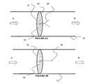
- FIG. 2A is a schematic illustration of a blood flow monitoring device comprising a thin wire filament in the presence of decreased blood flow;
- FIG. 2B is a schematic illustration of a blood flow monitoring device of FIG. 2A in the presence of increased blood flow
- FIG. 2C is a schematic illustration of another blood flow monitoring device comprising a thin wire filament in the presence of decreased blood flow;
- FIG. 2D is a schematic illustration of the blood flow monitoring device of FIG. 2C in the presence of increased blood flow.
- FIG. 3 is a schematic illustration of a blood flow monitoring device comprising a impeller.
- Strokes result from a sudden loss of brain function caused by a blockage or rupture of a blood vessel to the brain and is often characterized by loss of muscular control, diminution or loss of sensation or consciousness, dizziness, slurred speech, or other symptoms that vary with the extent and severity of the damage to the brain.
- the implantable prosthetic device is designed to decrease the instances of strokes, and other embolic events, such as pulmonary embolisms and ischemia in a patient by providing multiple pathway for the flow of fluids within a patient and a non-invasive method of monitoring the continued proper function of the device.
- FIG. 1 an implantable vascular prosthesis for connection to the vascular pathway of a patient is provided as depicted in FIG. 1 .
- Vascular prosthesis 10 includes a primary tube structure 12 defined by a proximal end A, a distal end B and a wall which separates the longitudinally exterior surface of primary tube structure 12 from the interior lumen.
- vascular prosthetic device 10 is implanted as described below, blood flows from the proximal end A of primary tube structure 12 towards the distal end B of primary structure 12 , as shown by arrows in the accompanying figures.
- the wall of primary tube structure 12 defines a longitudinally exterior surface and an interior lumen of predetermined diameter.
- Primary tube structure 12 is furcated at a predefined position into a plurality of secondary tube structures 14 , each of which is defined by a wall and interconnected to primary tube structure 12 such as to allow fluids to flow uninterruptedly from primary tube structure 12 into secondary tube structures 14 .
- Each of secondary tube structures 14 houses a filter 16 operative to trap embolic particles, e.g., blood clots, thrombus, debris, gas bubbles, or other particles that could possibly cause a debilitating embolism, including a stroke within the patient.
- the term “furcated” as used herein refers to branching, dividing, joining, or other connections between primary tube structure 12 and plural secondary tube structures 14 .
- FIG. 2A-2D each illustrate filter 16 positioned within one of the of secondary tube structures 14 .
- the filter in the other secondary tube structure can be similar.
- Filters 16 are preferably comprised of a frame 22 and a porous covering 24 coupled to frame 22 such that porous covering 24 covers the space defined by the frame.
- Frame 22 is preferably removably attached to the inside wall of secondary tube structures 14 such that entirety of filters 16 can be detached and removed from implantable vascular prosthesis 10 in the event it becomes clogged, dirty, or damaged, and needs to be cleaned or replaced.
- the surgeon surgically exposes the desired region for introduction of vascular prosthesis 10 .
- the desired site may be an area of occlusion or weakness in the patient's arteriovascular system, for example.
- An interruption of the patient's blood flow is performed in a known manner and vascular prosthesis is surgically implanted, sutured or otherwise secured in the desired location.
- Proper positioning of the prosthesis requires alignment of the lumen with the appropriate blood flow pathway such that the patient's blood flow is diverted through the lumen of primary tube structure 12 . Once diverted into the lumen of primary tube structure 12 the blood is directed into one of the secondary tube structures containing filters 16 .
- any mobile embolic particles contained within the blood are trapped by filters 16 , and the blood flow, now substantially devoid of embolic particles, continues in its course. If one of the of filters 16 become clogged, blood flow is continues through the another secondary tube structures 14 in an unhindered manner.
- the cross-sectional area of the longer of each secondary tube structures 14 is equivalent to that of the lumen of primary tube structure 12 . Accordingly, even a single fully clogged filter 16 will not substantially prohibit or limit normal blood flow.
- Filters 16 are designed such that they may be removed from secondary tube structures 14 , if so desired, for cleaning, repair or replacement. Note the tube structures can be repaired or replaced. To do so, blood flow can be stopped through the appropriate structure, with a clamp or the like, and blood can flow through the other tube structures during the procedure without adversely affecting the patient.
- Implantable vascular prosthesis 10 preferably comprises a device that indicates the blood flow through filters 16 which allows one to determine whether blood is passing through any one particular filters 16 .
- the means by which the blood flow is measured is dependent on the type of device employed and may consist of devices which facilitate either visual and/or aural monitoring of a patients blood flow.
- FIG. 2A illustrates one such blood flow indicator which consists of a thin wire filament 26 consisting of at least two prongs. In its resting state, the two prongs of thin wire filament 26 are biased in opposite directions, as shown in FIG. 2A . When subjected to pressures created by blood flow, thin wire filaments 26 are forced together, as shown in FIG. 2B .
- Thin wire filament 26 is preferably coupled to the distal side of filters 16 , such that when filter 16 is clogged by embolic particulates on its proximate side, the decrease in blood flow through filter 16 can be detected by visually observing the position of the two prongs of thin wire filament 26 in respect to one another using x-ray photography, magnetic resonance imaging or any other known imaging technique. A greater degree of separation between the two prongs of wire filament 26 indicates a corresponding decrease in blood flow in the associated secondary tube structures 14 . By observing the position of thin wire film 26 associated with each secondary tube structures 14 , one can determine which, if any, of filters are clogged or becoming clogged.
- FIG. 2C illustrates another blood flow indicator which consists of a thin wire filament 26 that is normally curved.
- thin wire filament 26 When subjected to pressures created by blood flow, thin wire filament 26 is straightened, as shown in FIG. 2D .
- Thin wire filament 26 is preferably coupled to the distal side of filters 16 , such that when filter 16 is clogged by embolic particulates on its proximate side, the decrease in blood flow through filter 16 can be detected by visually observing the curve, or lack thereof using x-ray photography, magnetic resonance imaging or any other known imaging technique.
- a greater degree of curvature of filament 26 indicates a corresponding decrease in blood flow in the associated secondary tube structures 14 .
- any imaging or sensing technique can be used to determine the status/position of the filaments.
- x-ray imaging, magnetic resonance imaging or other imaging techniques can be used.
- the blood flow indicator can have a detectable magnetic signature that permits blood flow detection using a magnetic induction or other magnetic sensor.
- RF sensors can be used.
- FIG. 3 illustrates another blood flow indicator 30 comprising a frame 32 removably attached to the inside wall of secondary tube structures 14 and a impeller 34 which is rotatably attached to the inside of frame 32 .
- Impeller 34 is set into either a clockwise or counterclockwise spin by the force of a patient's blood flow.
- the speed or relative degree of patient's blood flow can be determined by, for example, listening to audible signals created from the spinning of impeller 34 .
- a weak audible signal indicates decreased blood flow, suggesting filter 16 associated with a secondary tube structures 14 may be clogged.
- a stronger, more audible signal indicates that the blood is flowing through filter 16 at a rate relative to the audible signal produced.
- the blood flow indicator may be removed, if necessary, for cleaning, repair or replacement.
- the blood flow indicator may also be any known device for capable of emitting sounds corresponding to a given amount of blood flow within a fluid flow pathway.
- the blood flow indicator may consist of a valve or a plurality of valves, an impeller device, or any other known device capable of emitting specified sounds corresponding to a given amount of blood flow.
- any means of directly or indirectly monitoring blood flow can be used.
- any type of imaging e.g., x-ray photography, magnetic resonance imaging, etc.
- audible sensing e.g.
- magnetic induction sensing or other detection mechanism can be used to externally and non-invasively monitor the blood flow indicator.
- the blood flow indicator can have a detectable magnetic signature that permits blood flow detection using a magnetic sensor.
- Further RF sensors can be used.
- impeller 34 is upstream, i.e. proximal, with respect to filter 16 . This provides an added degree of safety. In the event that portions of impeller 34 break loose, they will be caught by filter 16 and not enter travel through the patients blood stream. However, impeller 34 can be positioned downstream of filter 34 if desired.
- Primary tube structures 12 and secondary tube structures 16 can be manufactured from various biocompatible materials.
- Teflon® brand polytetrafluoroethylene (PTFE) PTFE
- expanded tetrafluoroethylene stretched polytetrafluoroethylene
- stretched and expanded polytetrafluoroethylene is suitable for use with the invention.
- Polymer alloys are suitable as well.
- Dacron® brand polyester fiber, mandrel spun polyurethane, and silicone elastomer fibers are also well suited for use with the invention.
- Copolymeric materials can also be utilized.
- the internal diameter of the lumen of the primary tube structure and/or the secondary tube structures depends upon the intended use of each tube structure.
- lumina having internal diameters of from about 3 mm to about 24 mm are useful as vascular grafts.
- a tube structure intended for insertion in the arterial pathway can have a lumen internal diameter of from about 6 mm to about 18 mm.
- a tube structure for insertion in a venous pathway can have a lumen internal diameter from about 12 mm to about 24 mm.
- the outer diameter of the tube structures is generally not related to the internal lumen diameter.
- the thickness of the lumen walls will vary depending on the type of vascular graft. Generally, an arterial graft will require thicker walls than a venous graft. However, exact dimensions will depend on the specific purpose and environment in which the prosthetic device is employed.
- Porous covering 24 may be made from any number of suitable materials, and is preferably made from a flexible polymeric material with elastomeric properties chosen from a group consisting of polyurethane, polyethylene or a co-polymer thereof. Porous covering 24 may also comprise any number of and configuration of pores and preferably comprises regularly-spaced holes wherein the pore size is from about 20 microns to about 300 microns. However, the pore size can be any size suitable for the intended purpose and environment in which the filter is used. Further, any filter structures can be used.
- the implantable prosthetic device as disclosed as the preferred embodiments is not limited to use in the vascular system, but may also be employed in other fluid flow pathways, as well, including those within a patient's gastrointestinal system.
- the present embodiments are therefore to be considered in all respects as illustrative and not restrictive, the scope of the invention being indicated by the appended claims rather than the foregoing description, and all changes which come within the meaning and range of equivalency of the claim are therefore intended to be embraced therein.
Abstract
An implantable prosthetic for connection to a fluid flow pathway of a patient. The prosthetic is comprised of a primary tube structure which is in communication with a plurality of secondary tube structures each of which contains filters for trapping embolic particles, such as blood clots, air bubbles, thrombus. etc. within a fluid flow pathway within a patient. The prosthetic also contains a monitoring device to non-invasively the flow of fluids through a patient's fluid flow pathway.
Description
This application is a Divisional Application of U.S. patent application Ser. No. 11/039,835, which was filed on Jan. 24, 2005 and issued as U.S. Pat. No. 7,963,989 on Jun. 21, 2011, the contents of which are incorporated entirely herein by reference.
1. Field of the Invention
This invention relates to a implantable prosthetic device for connection to the fluid flow pathway of a patient, and more particularly to a implantable prosthetic device containing a plurality of tube structures having a filter for trapping objects such as embolic particles.
2. Discussion of Related Art
Increasing numbers and types of intralumenal procedures are being performed on medical patients. For example, there are intravascular blood flow measurement procedures, intravascular atherectomy procedures, intravascular drug therapy procedures, balloon angioplasty procedures, intravascular stent installation procedures, and even intravascular coronary bypass procedures (see, for example, U.S. Pat. No. 5,976,178 to Goldsteen, et al. which is herein incorporated by reference in its entirety). A concern commonly encountered in all these techniques is the accidental release of portions of the clots, plague, thrombus, debris, gas bubbles, or other embolic particulates, resulting in emboli which can lodge elsewhere in the vascular system. The creation and release of embolic particles can also occur spontaneously, absent medical intervention, especially in patients with blood-clotting disorders, such as phlebitis. Such emboli may be extremely dangerous to the patient, and may result in myocardial infarction, stroke, or limb ischemia.
Various devices have been developed to decrease the risk of embolism in patients during such procedures or suffering from such medical conditions. For example, U.S. Pat. No. 5,800,525 to Bachinski, et al. discloses a single bodily fluid filter with an elastic tubular framework that can be installed intralumenally to trap embolic particles in a bodily fluid conduit. However, since this device consists of a single filter, it does not provide for an alternative fluid flow path in the event that the filter becomes clogged.
U.S. Pat. No. 6,168,579 to Tsugita discloses a guidewire insertable within a guiding catheter which allows for the temporary placement of a filter in an artery or vein to capture atherosclerotic plaques and/or thrombi to capture embolic particles generated during endovascular procedures. This device, however, is designed only to capture embolic particles dislodged during the course of medical procedures and cannot be surgically implanted into a fluid flow pathway for long-term protection against naturally occurring emobolic particles.
U.S. Pat. No. 5,370,681 Herweck et al. discloses a polyumenal implantable organ for sustained release of a bioactive material into a fluid flow pathway of a patient. The device comprises a body which defines a multiplicity of capillary lumina and is adapted for connection to the patient's fluid flow pathway to establish fluid flow through the capillary lumina. By seeding selected lumina of the device with a bioactive material, such as a therapeutic agent, diagnostic agent, etc. for contact with the body fluid, such as blood, the fluid can be treated as it passes through the device. This device does not provide a means by which embolic particles are filtered within the fluid flow pathway, and thus, does not serve to decrease a patient's risk of stroke, pulmonary embolism or other potentially deadly medical condition.
U.S. Pat. No. 5,197,976 to Herweck et al. discloses a vascular prosthesis comprising a plurality of parallel tube structures which are attached to one another over at least a portion of their longitudinal axis to form a branched arterial or venous graft for capable of being implanted without the necessity of suturing two grafts together. The tube structures of this device, however, do not comprise filtering devices for capturing hazardous embolic particles within a patient's fluid flow pathway.
Obviously, there are still major disadvantages associated with the existing technology which must be overcome. Specifically, the present day technology fails to provide patients with long-term protection against the potentially fatal conditions that result from blocked fluid flow pathways, including stroke, pulmonary embolism, and ischemia. Until now, there have been no implantable prosthetic devices containing multiple fluid flow pathways and filtering mechanisms to ensure the adequacy of the fluid flow within a patient capable of overcoming this technological shortfall.
It is an object of the present invention to provide a device which decreases the instances of stroke, embolism, and other potentially harmful effects associated with the presence of foreign particles within the fluid flow pathway of a patient.
It is another object of the invention provide an implantable prosthetic device for connection to the fluid flow pathway of a patient that helps to maintain long-term adequate flow of fluids through fluid flow pathways by filtering foreign particles and providing a means for monitoring the blood flow through the device.
A first aspect of the invention is a primary tube structure having a proximal end, a distal end, and a wall, wherein the wall defines an interior lumen of predetermined diameter. The primary tube structure is furcated at a predefined position between the proximal end and distal end of the primary tube structure into a plurality of secondary tube structures. The secondary tube structures comprise a wall which defines an interior lumen of predetermined diameter. The interior lumen defined by the wall of the primary tube structure is in communication with the interior lumen defined by the secondary tube structures. The lumen of each of the tube structure contains a filter.
The primary tube structure and secondary tube structures have a biocompatible exterior surface and are preferably composed of polytetrafluoroethylene selected from the group consisting of expanded tetrafluoroethylene, stretched polytetrafluoroethylene, and stretched and expanded polytetrafluoroethylene. The primary tube structure and secondary tube structures may also consist of a copolymeric material.
The filter positioned within the secondary tube structures is comprised of a frame and a porous covering coupled to the frame such that the porous covering covers the space defined by the frame. The pore size of the porous covering is preferably about 20 to about 300 microns and composed of a flexible polymeric material such as polyurethane, polyethylene or a copolymer thereof capable of stretching to achieve the diameter of a fluid flow pathway. In a preferred embodiment, the filters may be removed from the secondary tube structures for cleaning or replacement. The primary tube structure may also include a fluid flow monitoring device to ensure the operability of the invention.
In a second aspect of the invention provided is a method for inserting the implantable prosthetic device as described into a predefined location within a patient by surgically exposing a predefined region for insertion of the implantable prosthetic device and securing the device within the predefined region.
In a third aspect of the invention provided is a method of non-invasively monitoring fluid flow through an implantable prosthetic connected to a fluid flow pathway of a patient. This method comprises the steps of locating an external anatomical area on a patient proximate the situs of an implantable prosthetic device implanted within a fluid flow pathway of the patient and
detecting fluid flow through said implantable prosthetic device implanted within a patient's fluid flow pathway using a fluid flow monitoring device.
Strokes result from a sudden loss of brain function caused by a blockage or rupture of a blood vessel to the brain and is often characterized by loss of muscular control, diminution or loss of sensation or consciousness, dizziness, slurred speech, or other symptoms that vary with the extent and severity of the damage to the brain. The implantable prosthetic device, the preferred embodiments of which are herein disclosed and described is designed to decrease the instances of strokes, and other embolic events, such as pulmonary embolisms and ischemia in a patient by providing multiple pathway for the flow of fluids within a patient and a non-invasive method of monitoring the continued proper function of the device.
In a first embodiment, an implantable vascular prosthesis for connection to the vascular pathway of a patient is provided as depicted in FIG. 1 . Vascular prosthesis 10 includes a primary tube structure 12 defined by a proximal end A, a distal end B and a wall which separates the longitudinally exterior surface of primary tube structure 12 from the interior lumen. For purposes of describing the invention, it is herein assumed that when vascular prosthetic device 10 is implanted as described below, blood flows from the proximal end A of primary tube structure 12 towards the distal end B of primary structure 12, as shown by arrows in the accompanying figures. The wall of primary tube structure 12 defines a longitudinally exterior surface and an interior lumen of predetermined diameter. Primary tube structure 12 is furcated at a predefined position into a plurality of secondary tube structures 14, each of which is defined by a wall and interconnected to primary tube structure 12 such as to allow fluids to flow uninterruptedly from primary tube structure 12 into secondary tube structures 14. Note that the angles at which secondary tube structures interest with primary tube structures is illustrated as being exaggerated for clarity. Such angles preferably would be suitably set to avoid turbulent flow of blood. Each of secondary tube structures 14 houses a filter 16 operative to trap embolic particles, e.g., blood clots, thrombus, debris, gas bubbles, or other particles that could possibly cause a debilitating embolism, including a stroke within the patient. The term “furcated” as used herein refers to branching, dividing, joining, or other connections between primary tube structure 12 and plural secondary tube structures 14.
In operation, the surgeon surgically exposes the desired region for introduction of vascular prosthesis 10. The desired site may be an area of occlusion or weakness in the patient's arteriovascular system, for example. An interruption of the patient's blood flow is performed in a known manner and vascular prosthesis is surgically implanted, sutured or otherwise secured in the desired location. Proper positioning of the prosthesis requires alignment of the lumen with the appropriate blood flow pathway such that the patient's blood flow is diverted through the lumen of primary tube structure 12. Once diverted into the lumen of primary tube structure 12 the blood is directed into one of the secondary tube structures containing filters 16. Any mobile embolic particles contained within the blood are trapped by filters 16, and the blood flow, now substantially devoid of embolic particles, continues in its course. If one of the of filters 16 become clogged, blood flow is continues through the another secondary tube structures 14 in an unhindered manner. Preferably, the cross-sectional area of the longer of each secondary tube structures 14 is equivalent to that of the lumen of primary tube structure 12. Accordingly, even a single fully clogged filter 16 will not substantially prohibit or limit normal blood flow.
Implantable vascular prosthesis 10 preferably comprises a device that indicates the blood flow through filters 16 which allows one to determine whether blood is passing through any one particular filters 16. The means by which the blood flow is measured is dependent on the type of device employed and may consist of devices which facilitate either visual and/or aural monitoring of a patients blood flow. FIG. 2A illustrates one such blood flow indicator which consists of a thin wire filament 26 consisting of at least two prongs. In its resting state, the two prongs of thin wire filament 26 are biased in opposite directions, as shown in FIG. 2A . When subjected to pressures created by blood flow, thin wire filaments 26 are forced together, as shown in FIG. 2B . Thin wire filament 26 is preferably coupled to the distal side of filters 16, such that when filter 16 is clogged by embolic particulates on its proximate side, the decrease in blood flow through filter 16 can be detected by visually observing the position of the two prongs of thin wire filament 26 in respect to one another using x-ray photography, magnetic resonance imaging or any other known imaging technique. A greater degree of separation between the two prongs of wire filament 26 indicates a corresponding decrease in blood flow in the associated secondary tube structures 14. By observing the position of thin wire film 26 associated with each secondary tube structures 14, one can determine which, if any, of filters are clogged or becoming clogged.
Any imaging or sensing technique can be used to determine the status/position of the filaments. For example, x-ray imaging, magnetic resonance imaging or other imaging techniques can be used. Further, the blood flow indicator can have a detectable magnetic signature that permits blood flow detection using a magnetic induction or other magnetic sensor. Further RF sensors can be used.
Note that in FIG. 3 , impeller 34 is upstream, i.e. proximal, with respect to filter 16. This provides an added degree of safety. In the event that portions of impeller 34 break loose, they will be caught by filter 16 and not enter travel through the patients blood stream. However, impeller 34 can be positioned downstream of filter 34 if desired.
The internal diameter of the lumen of the primary tube structure and/or the secondary tube structures depends upon the intended use of each tube structure. In general, lumina having internal diameters of from about 3 mm to about 24 mm are useful as vascular grafts. For example, a tube structure intended for insertion in the arterial pathway can have a lumen internal diameter of from about 6 mm to about 18 mm. A tube structure for insertion in a venous pathway can have a lumen internal diameter from about 12 mm to about 24 mm. The outer diameter of the tube structures is generally not related to the internal lumen diameter. The thickness of the lumen walls will vary depending on the type of vascular graft. Generally, an arterial graft will require thicker walls than a venous graft. However, exact dimensions will depend on the specific purpose and environment in which the prosthetic device is employed.
The invention may be embodied in other specific forms without departing from the spirit or essential characteristics thereof. For example, the implantable prosthetic device as disclosed as the preferred embodiments is not limited to use in the vascular system, but may also be employed in other fluid flow pathways, as well, including those within a patient's gastrointestinal system. The present embodiments are therefore to be considered in all respects as illustrative and not restrictive, the scope of the invention being indicated by the appended claims rather than the foregoing description, and all changes which come within the meaning and range of equivalency of the claim are therefore intended to be embraced therein.
Claims (14)
1. A method for inserting an implantable prosthetic device for connection to a fluid flow pathway of a patient, comprising the steps of:
identifying a fluid flow pathway of a patient;
surgically exposing a first region of said fluid flow pathway for insertion of an implantable prosthetic device;
securing a proximal end of said implantable prosthetic device to said first region of said fluid flow pathway, said implantable prosthetic device extending from said proximal end to a distal end, said implantable prosthetic device including a proximal structure at said proximal end, a distal structure at said distal end, and a furcated structure disposed between said proximal structure and said distal structure, said proximal structure and said distal structure only including a respective single tube, said furcated structure including a plurality of tubes, said single tube of said proximal structure being connected to each of said plurality of tubes of said furcated structure to allow flow from said single tube of said proximal structure to each of said plurality of tubes of said furcated structure, each of said plurality of tubes of said furcated structure being connected to said single tube of said distal end to allow flow from each of said plurality of tubes of said furcated structure to said single tube of said distal end;
surgically exposing a second region of said fluid flow pathway; and
securing said distal end of said implantable prosthetic device to said second region of said fluid flow pathway,
wherein said implantable prosthetic device, when secured to said fluid flow pathway, introduces said furcated structure between said first region and second region of said fluid flow pathway, and fluid flows through said first region of said fluid flow pathway into said single tube of said proximate structure, said plurality of tubes of said furcated structure, and said single tube of said distal structure and back into said fluid flow pathway at said second region of said fluid flow pathway, said plurality of tubes of said furcated structure and said single tube of said distal structure only receiving fluid that flows through said single tube of said proximate structure, and
said single tube of said proximate structure has a first cross-sectional area that is substantially equivalent to a respective cross-sectional area of at least one of said plurality of tubes of said furcated structure.
2. The method of claim 1 , wherein said implantable prosthetic device includes a biocompatible exterior surface.
3. The method of claim 1 , wherein said single tube of said proximate structure, said plurality of tubes of furcated structure, and said single tube of said distal structure consist of polytetrafluoroethylene.
4. The method of claim 3 , wherein said polytetrafluoroethylene is selected from the group consisting of expanded tetrafluoroethylene, stretched polytetrafluoroethylene, and stretched and expanded polytetrafluoroethylene.
5. The method of claim 1 , wherein said single tube of said proximate structure, said plurality of tubes of said furcated structure, and said single tube of said distal structure consist of copolymeric material.
6. The method of claim 1 , wherein a filter is disposed in each of said plurality of tubes of said furcated structure, and said filter is comprised of a frame and a porous covering coupled to said frame such that said porous covers the space defined by said frame.
7. The method of claim 6 , wherein the pore size of said porous covering is about 20 to about 300 microns.
8. The method of claim 6 , wherein the said porous covering is a flexible polymeric material comprising regularly-spaced holes therein.
9. The method of claim 8 , wherein said flexible polymeric material is chosen from the group consisting of polyurethane, polyethylene or a copolymer thereof.
10. The method of claim 8 , wherein said flexible polymeric material is an elastomeric material capable of stretching to achieve the diameter of a fluid flow pathway.
11. The method of claim 1 , wherein a filter is disposed in each of said plurality of tubes of said furcated structure, and said filter is removable.
12. The method of claim 1 , wherein each of said plurality of tubes of said furcated structure includes at least one fluid flow indicator.
13. The method of claim 12 , wherein said at least one fluid flow indicator is a thin wire filament.
14. The method of claim 12 , wherein said at least one fluid flow indicator is an impeller.
Priority Applications (2)
| Application Number | Priority Date | Filing Date | Title |
|---|---|---|---|
| US13/164,657 US8828076B2 (en) | 2005-01-24 | 2011-06-20 | Implantable prosthetic device for connection to a fluid flow pathway of a patient |
| US14/479,506 US20140379062A1 (en) | 2005-01-24 | 2014-09-08 | Implantable prosthetic device for connection to a fluid flow pathway of a patient and methods of using the same |
Applications Claiming Priority (2)
| Application Number | Priority Date | Filing Date | Title |
|---|---|---|---|
| US11/039,835 US7963989B2 (en) | 2005-01-24 | 2005-01-24 | Implantable prosthetic device for connection to a fluid flow pathway of a patient |
| US13/164,657 US8828076B2 (en) | 2005-01-24 | 2011-06-20 | Implantable prosthetic device for connection to a fluid flow pathway of a patient |
Related Parent Applications (1)
| Application Number | Title | Priority Date | Filing Date |
|---|---|---|---|
| US11/039,835 Division US7963989B2 (en) | 2005-01-24 | 2005-01-24 | Implantable prosthetic device for connection to a fluid flow pathway of a patient |
Related Child Applications (1)
| Application Number | Title | Priority Date | Filing Date |
|---|---|---|---|
| US14/479,506 Division US20140379062A1 (en) | 2005-01-24 | 2014-09-08 | Implantable prosthetic device for connection to a fluid flow pathway of a patient and methods of using the same |
Publications (2)
| Publication Number | Publication Date |
|---|---|
| US20110245913A1 US20110245913A1 (en) | 2011-10-06 |
| US8828076B2 true US8828076B2 (en) | 2014-09-09 |
Family
ID=36697944
Family Applications (3)
| Application Number | Title | Priority Date | Filing Date |
|---|---|---|---|
| US11/039,835 Expired - Fee Related US7963989B2 (en) | 2005-01-24 | 2005-01-24 | Implantable prosthetic device for connection to a fluid flow pathway of a patient |
| US13/164,657 Expired - Fee Related US8828076B2 (en) | 2005-01-24 | 2011-06-20 | Implantable prosthetic device for connection to a fluid flow pathway of a patient |
| US14/479,506 Abandoned US20140379062A1 (en) | 2005-01-24 | 2014-09-08 | Implantable prosthetic device for connection to a fluid flow pathway of a patient and methods of using the same |
Family Applications Before (1)
| Application Number | Title | Priority Date | Filing Date |
|---|---|---|---|
| US11/039,835 Expired - Fee Related US7963989B2 (en) | 2005-01-24 | 2005-01-24 | Implantable prosthetic device for connection to a fluid flow pathway of a patient |
Family Applications After (1)
| Application Number | Title | Priority Date | Filing Date |
|---|---|---|---|
| US14/479,506 Abandoned US20140379062A1 (en) | 2005-01-24 | 2014-09-08 | Implantable prosthetic device for connection to a fluid flow pathway of a patient and methods of using the same |
Country Status (1)
| Country | Link |
|---|---|
| US (3) | US7963989B2 (en) |
Families Citing this family (35)
| Publication number | Priority date | Publication date | Assignee | Title |
|---|---|---|---|---|
| US6471635B1 (en) | 2000-02-10 | 2002-10-29 | Obtech Medical Ag | Anal incontinence disease treatment with controlled wireless energy supply |
| US6450173B1 (en) | 1999-08-12 | 2002-09-17 | Obtech Medical Ag | Heartburn and reflux disease treatment with controlled wireless energy supply |
| US6464628B1 (en) | 1999-08-12 | 2002-10-15 | Obtech Medical Ag | Mechanical anal incontinence |
| US6482145B1 (en) | 2000-02-14 | 2002-11-19 | Obtech Medical Ag | Hydraulic anal incontinence treatment |
| BR0108223B1 (en) | 2000-02-10 | 2009-08-11 | mechanical apparatus for the treatment of impotence. | |
| DE60113965T2 (en) | 2000-02-10 | 2006-07-06 | Potencia Medical Ag | TREATMENT OF HARNINE CONTINENCE WITH WIRELESS ENERGY SUPPLY |
| BR0108225B1 (en) | 2000-02-10 | 2010-02-09 | apparatus for the treatment of urinary incontinence. | |
| CN101138528B (en) | 2000-02-11 | 2015-02-25 | 波坦蒂卡股份公司 | Impotence treatment apparatus with energy transforming means |
| DE60131726T2 (en) | 2000-02-11 | 2008-11-06 | Potencia Medical Ag | CONTROLLED IMPOTENA TREATMENT |
| AU778113B2 (en) | 2000-02-14 | 2004-11-18 | Implantica Patent Ltd. | Male impotence prosthesis apparatus with wireless energy supply |
| US20030100929A1 (en) * | 2000-02-14 | 2003-05-29 | Peter Forsell | Controlled penile prosthesis |
| DE60111019T2 (en) | 2000-02-14 | 2006-05-11 | Potencia Medical Ag | PROSTHESIS |
| US7147661B2 (en) | 2001-12-20 | 2006-12-12 | Boston Scientific Santa Rosa Corp. | Radially expandable stent |
| JP2007530089A (en) * | 2003-07-14 | 2007-11-01 | ユニバーシティ・オブ・リムリック | Vascular graft |
| EP2244758A4 (en) * | 2008-01-28 | 2016-12-14 | Kirk Promotion Ltd | A drainage device comprising an active filter |
| CA2776467A1 (en) | 2008-10-10 | 2010-04-15 | Peter Forsell | Fastening means for implantable medical control assembly |
| EP2349170B1 (en) | 2008-10-10 | 2023-09-27 | Implantica Patent Ltd. | Apparatus for the treatment of female sexual dysfunction |
| SI2349383T1 (en) | 2008-10-10 | 2022-02-28 | Medicaltree Patent Ltd. | Heart help device and system |
| US9526649B2 (en) | 2008-10-10 | 2016-12-27 | Peter Forsell | Method and instrument for treating obesity |
| US10219898B2 (en) | 2008-10-10 | 2019-03-05 | Peter Forsell | Artificial valve |
| EP2349025B1 (en) | 2008-10-10 | 2015-09-16 | Kirk Promotion LTD. | A system, an apparatus, and a method for treating a sexual dysfunctional female patient |
| WO2010042018A1 (en) | 2008-10-10 | 2010-04-15 | Milux Holding S.A. | Heart help device, system and method |
| US9949812B2 (en) | 2009-07-17 | 2018-04-24 | Peter Forsell | Vaginal operation method for the treatment of anal incontinence in women |
| US10952836B2 (en) | 2009-07-17 | 2021-03-23 | Peter Forsell | Vaginal operation method for the treatment of urinary incontinence in women |
| US20120035645A1 (en) * | 2010-08-05 | 2012-02-09 | Rainbow Medical Ltd. | Dynamic and static blood filters |
| US9386991B2 (en) | 2012-02-02 | 2016-07-12 | Rainbow Medical Ltd. | Pressure-enhanced blood flow treatment |
| JP5650697B2 (en) * | 2012-09-06 | 2015-01-07 | 富士フイルム株式会社 | Air supply system |
| CA3094655C (en) * | 2013-01-22 | 2023-01-24 | Anuncia, Inc. | Systems and methods for shunting fluid |
| US10792185B2 (en) | 2014-02-14 | 2020-10-06 | Zoll Circulation, Inc. | Fluid cassette with polymeric membranes and integral inlet and outlet tubes for patient heat exchange system |
| JP6544795B2 (en) * | 2015-03-13 | 2019-07-17 | テルモ株式会社 | Medical device |
| JP6436572B2 (en) * | 2015-03-13 | 2018-12-12 | テルモ株式会社 | Medical device |
| JP6445363B2 (en) * | 2015-03-20 | 2018-12-26 | テルモ株式会社 | Medical device |
| US10028820B2 (en) | 2015-04-14 | 2018-07-24 | Cook Medical Technologies Llc | Carotid artery blood filter plugging alarm |
| EP3525835A4 (en) | 2016-10-13 | 2020-07-15 | Anuncia, Inc. | Shunt flushers and related methods |
| US11272945B2 (en) | 2018-10-10 | 2022-03-15 | Innova Vascular, Inc. | Device for removing an embolus |
Citations (17)
| Publication number | Priority date | Publication date | Assignee | Title |
|---|---|---|---|---|
| US5197976A (en) | 1991-09-16 | 1993-03-30 | Atrium Medical Corporation | Manually separable multi-lumen vascular graft |
| US5370681A (en) | 1991-09-16 | 1994-12-06 | Atrium Medical Corporation | Polyumenal implantable organ |
| US5800525A (en) | 1997-06-04 | 1998-09-01 | Vascular Science, Inc. | Blood filter |
| US5967986A (en) | 1997-11-25 | 1999-10-19 | Vascusense, Inc. | Endoluminal implant with fluid flow sensing capability |
| US6110201A (en) * | 1999-02-18 | 2000-08-29 | Venpro | Bifurcated biological pulmonary valved conduit |
| US6168579B1 (en) | 1999-08-04 | 2001-01-02 | Scimed Life Systems, Inc. | Filter flush system and methods of use |
| US6428559B1 (en) | 2001-04-03 | 2002-08-06 | Cordis Corporation | Removable, variable-diameter vascular filter system |
| US20030114923A1 (en) | 2001-11-14 | 2003-06-19 | Swanick Thomas M. | Graft and method of making |
| US20030120330A1 (en) | 2001-12-20 | 2003-06-26 | The Cleveland Clinic Foundation | Delivery system and method for deploying an endovascular prosthesis |
| US6585756B1 (en) | 1999-05-14 | 2003-07-01 | Ernst P. Strecker | Implantable lumen prosthesis |
| US20040210250A1 (en) * | 2001-10-05 | 2004-10-21 | Scimed Life Systems, Inc. | Emboli capturing device and method of manufacture therefor |
| WO2005004752A1 (en) * | 2003-07-14 | 2005-01-20 | University Of Limerik | A vascular graft |
| US20050049692A1 (en) * | 2003-09-02 | 2005-03-03 | Numamoto Michael J. | Medical device for reduction of pressure effects of cardiac tricuspid valve regurgitation |
| US20050267322A1 (en) * | 2004-05-25 | 2005-12-01 | Larose Jeffrey A | Sensorless flow estimation for implanted ventricle assist device |
| US7226476B2 (en) | 2002-12-06 | 2007-06-05 | G.A.M.A.-H.S. S.R.L. | Prosthesis for large blood vessels |
| US7229472B2 (en) | 2000-11-16 | 2007-06-12 | Cordis Corporation | Thoracic aneurysm repair prosthesis and system |
| US7261733B1 (en) | 2002-06-07 | 2007-08-28 | Endovascular Technologies, Inc. | Endovascular graft with sensors design and attachment methods |
-
2005
- 2005-01-24 US US11/039,835 patent/US7963989B2/en not_active Expired - Fee Related
-
2011
- 2011-06-20 US US13/164,657 patent/US8828076B2/en not_active Expired - Fee Related
-
2014
- 2014-09-08 US US14/479,506 patent/US20140379062A1/en not_active Abandoned
Patent Citations (18)
| Publication number | Priority date | Publication date | Assignee | Title |
|---|---|---|---|---|
| US5370681A (en) | 1991-09-16 | 1994-12-06 | Atrium Medical Corporation | Polyumenal implantable organ |
| US5197976A (en) | 1991-09-16 | 1993-03-30 | Atrium Medical Corporation | Manually separable multi-lumen vascular graft |
| US5800525A (en) | 1997-06-04 | 1998-09-01 | Vascular Science, Inc. | Blood filter |
| US5967986A (en) | 1997-11-25 | 1999-10-19 | Vascusense, Inc. | Endoluminal implant with fluid flow sensing capability |
| US7022134B1 (en) | 1999-02-18 | 2006-04-04 | Medtronic, Inc. | Bifurcated biological pulmonary valved conduit |
| US6110201A (en) * | 1999-02-18 | 2000-08-29 | Venpro | Bifurcated biological pulmonary valved conduit |
| US6585756B1 (en) | 1999-05-14 | 2003-07-01 | Ernst P. Strecker | Implantable lumen prosthesis |
| US6168579B1 (en) | 1999-08-04 | 2001-01-02 | Scimed Life Systems, Inc. | Filter flush system and methods of use |
| US7229472B2 (en) | 2000-11-16 | 2007-06-12 | Cordis Corporation | Thoracic aneurysm repair prosthesis and system |
| US6428559B1 (en) | 2001-04-03 | 2002-08-06 | Cordis Corporation | Removable, variable-diameter vascular filter system |
| US20040210250A1 (en) * | 2001-10-05 | 2004-10-21 | Scimed Life Systems, Inc. | Emboli capturing device and method of manufacture therefor |
| US20030114923A1 (en) | 2001-11-14 | 2003-06-19 | Swanick Thomas M. | Graft and method of making |
| US20030120330A1 (en) | 2001-12-20 | 2003-06-26 | The Cleveland Clinic Foundation | Delivery system and method for deploying an endovascular prosthesis |
| US7261733B1 (en) | 2002-06-07 | 2007-08-28 | Endovascular Technologies, Inc. | Endovascular graft with sensors design and attachment methods |
| US7226476B2 (en) | 2002-12-06 | 2007-06-05 | G.A.M.A.-H.S. S.R.L. | Prosthesis for large blood vessels |
| WO2005004752A1 (en) * | 2003-07-14 | 2005-01-20 | University Of Limerik | A vascular graft |
| US20050049692A1 (en) * | 2003-09-02 | 2005-03-03 | Numamoto Michael J. | Medical device for reduction of pressure effects of cardiac tricuspid valve regurgitation |
| US20050267322A1 (en) * | 2004-05-25 | 2005-12-01 | Larose Jeffrey A | Sensorless flow estimation for implanted ventricle assist device |
Also Published As
| Publication number | Publication date |
|---|---|
| US20110245913A1 (en) | 2011-10-06 |
| US20060167539A1 (en) | 2006-07-27 |
| US7963989B2 (en) | 2011-06-21 |
| US20140379062A1 (en) | 2014-12-25 |
Similar Documents
| Publication | Publication Date | Title |
|---|---|---|
| US8828076B2 (en) | Implantable prosthetic device for connection to a fluid flow pathway of a patient | |
| US8388644B2 (en) | Embolic protection device and method of use | |
| US6623507B2 (en) | Vascular filtration device | |
| JP5960713B2 (en) | Device and method for stent graft in situ (INSITU) fenestration at vascular branch site | |
| US5980555A (en) | Method of using cannula with associated filter during cardiac surgery | |
| US6929653B2 (en) | Apparatus and method for replacing aortic valve | |
| US7229463B2 (en) | Vascular filter system for cardiopulmonary bypass | |
| US6589264B1 (en) | Aortic occluder with associated filter and methods of use during cardiac surgery | |
| US20200054434A1 (en) | Intravascular Device With Multiple Leaflets | |
| US20160151141A1 (en) | High Flow Embolic Protection Device | |
| US20060015136A1 (en) | Vascular filter with improved strength and flexibility | |
| EP1086663A1 (en) | Tubular graft formed of monofilament fibers | |
| CN112386305A (en) | Double-layer filter screen anti-embolism far-end protection device | |
| CN211460682U (en) | Embolism collection device and embolism protection system | |
| CN213940889U (en) | Double-layer filter screen anti-embolism far-end protection device | |
| CN216221839U (en) | Thrombus filter device | |
| US20230346535A1 (en) | Method of Evaluating an Embolic Filter | |
| CN116138922A (en) | Thrombus filtering device | |
| CN113017910A (en) | Embolism collection device and embolism protection system | |
| Michael | patent is extended or adjusted under 35 DE 4 1 () 1935* 7/1992 USC 154 (b) by 258 days. SAAAAAA |
Legal Events
| Date | Code | Title | Description |
|---|---|---|---|
| FEPP | Fee payment procedure |
Free format text: MAINTENANCE FEE REMINDER MAILED (ORIGINAL EVENT CODE: REM.) |
|
| LAPS | Lapse for failure to pay maintenance fees |
Free format text: PATENT EXPIRED FOR FAILURE TO PAY MAINTENANCE FEES (ORIGINAL EVENT CODE: EXP.); ENTITY STATUS OF PATENT OWNER: SMALL ENTITY |
|
| STCH | Information on status: patent discontinuation |
Free format text: PATENT EXPIRED DUE TO NONPAYMENT OF MAINTENANCE FEES UNDER 37 CFR 1.362 |
|
| FP | Lapsed due to failure to pay maintenance fee |
Effective date: 20180909 |