US8831273B2 - Methods and systems for pre-processing two-dimensional image files to be converted to three-dimensional image files - Google Patents
Methods and systems for pre-processing two-dimensional image files to be converted to three-dimensional image files Download PDFInfo
- Publication number
- US8831273B2 US8831273B2 US13/230,750 US201113230750A US8831273B2 US 8831273 B2 US8831273 B2 US 8831273B2 US 201113230750 A US201113230750 A US 201113230750A US 8831273 B2 US8831273 B2 US 8831273B2
- Authority
- US
- United States
- Prior art keywords
- dimensional
- image
- discrete elements
- reconstructed
- conversion process
- Prior art date
- Legal status (The legal status is an assumption and is not a legal conclusion. Google has not performed a legal analysis and makes no representation as to the accuracy of the status listed.)
- Active, expires
Links
Images


Classifications
-
- G—PHYSICS
- G06—COMPUTING; CALCULATING OR COUNTING
- G06T—IMAGE DATA PROCESSING OR GENERATION, IN GENERAL
- G06T11/00—2D [Two Dimensional] image generation
Definitions
- the techniques discussed herein generally relate to methods and systems for pre-processing Two-Dimensional (“2D”) images that are used for generation of corresponding Three-Dimensional (“3D”) images. More specifically, the techniques relate to methods and systems of processing 2D images to avoid subsequent occlusions and transparencies that may arise during 3D conversion of the 2D images.
- 2D Two-Dimensional
- 3D Three-Dimensional
- Converting monoscopic, or 2D, image sequences to stereoscopic, or 3D, sequences may be accomplished through any one of the numerous existing processes.
- One of the most common conversion processes requires that discrete elements of an image be segmented so that the discrete elements can then be individually modified during the conversion process.
- these individual discrete elements are offset horizontally and re-composited into a new position.
- the new position is determined by referencing the inherent monoscopic depth cues within the image sequence itself, by artistic design, or a combination of both methodologies.
- the segmentation, modification, and compositing steps create an alternate viewing perspective of the original image sequence.
- the creation of an alternate view may be performed once, in which case the observer views the original 2D image with one eye, and the second modified alternate view with the other eye.
- the creation of an alternate view can be carried out twice, with the horizontal modifications and offsets being carried out in opposite directions between the two alternate views. In this latter case, two entirely new viewing perspectives are created, and the observer views one of them with one eye and the other with the second eye.
- the present application describes methods and systems of efficiently and effectively preparing images to be converted from 2D to 3D and specifically, treating occlusions and transparencies in the images.
- the techniques presented herein include a process that includes the steps of segmenting the discrete parts of a single or plurality of monoscopic image sequences, and replacing the estimated occluded areas before the images are converted from monoscopic 2D to stereoscopic 3D.
- the discrete monoscopic element sequences are then ingested individually into the 2D to 3D conversion process.
- the monoscopic element sequences are then re-composited to approximate the original monoscopic image sequence. This process occludes much of image data in the processed layers, but the inherent layers remain completely intact and controllable within the composite.
- These layered elements can then be processed with horizontal offsets and modifications during the 2D to 3D conversion process. The new view(s) will reveal previously processed image data, thus preventing the need to fill any occlusions subsequent to or during the 2D-3D conversion process.
- the technique discussed herein commences in the same manner as a conventional 2D to 3D process: with the segmentation of discrete elements in the monoscopic image sequence.
- This task is performed, for example, after the monoscopic image sequence has been digitally encoded and ingested into a computer.
- the segmentation is digitally performed multiple ways, using a variety of visual effects techniques and software.
- Techniques may include, but are not limited to, rotoscoping, procedural color keys, edge detection, and/or motion vector estimation. These discrete elements have different perceived depth planes within the scene. Different depth planes are ascertained by the analysis of monoscopic visual depth cues that dictate the relative depths of elements.
- Some monoscopic depth may be determined using cues including, but not limited to, atmospheric contrast, relative size, occlusion, and perceived speed over distance traveled.
- the discrete depth elements are segmented throughout the entire monoscopic sequence. At this point, the discrete elements may be offset and modified horizontally in order to estimate the amount of occluded area that will be revealed during the conversion process.
- the discrete element sequences have the estimated monoscopic occluded image areas reconstructed.
- This can be accomplished in various ways using a wide variety of visual effects techniques and software.
- Techniques for monoscopic image reconstruction may include, but are not limited to, digital matte painting, camera tracking and matchmoving, artificial particle creation, procedural digital painting techniques, computer generated replacement objects, motion estimated automatic monoscopic paint filling, artificial grain, and/or digital noise creation.
- sequences may be re-composited to approximate the original monoscopic image sequence, before it was segmented into element sequences that were reconstructed.
- the re-composite process can be carried out through various digital compositing operations. Operations may include, but are not limited to, Over, Add, Screen, Mix, Multiply, Divide, etc. These operations may be carried out in 2D compositing space, where positioning in only the X and Y axis is possible, in 2.5D compositing space, where limited Z-axis positioning is possible in addition to X and Y axis positioning, or in 3D compositing space, where complete positioning in all three axis is available.
- the option exists to pre-compose the individual monoscopic element sequences as encoded RGB, RGBA, or RGB and Alpha image file sequences.
- the encoded files may be, but are not limited to, Jpeg, Tiff, Cineon, DPX, PNG, openEXR, bitmap, Targa, Photoshop Document, and/or container files such as mpeg, QuickTime, mp4, and/or Matroska.
- the eventual 2D to 3D conversion process may be carried out on the original monoscopic image sequence in parallel with the individual monoscopic element sequence reconstruction and re-composite.
- the re-composite may be combined with the 2D to 3D conversion process before finalization.
- the individual monoscopic element sequence reconstruction 2D to 3D process is not being done in parallel with the 2D to 3D conversion process, the re-composite may be ingested into that process to be completed.
- the techniques discussed herein allow for greater control when converting monoscopic image sequences that exhibit semi-transparent elements.
- These elements may include, but are not limited to, smoke, reflections, motion blur, defocused elements, haze, volumetric lighting, water splashes or droplets, ethereal elements, and/or holograms.
- One exemplary embodiment is a method of preparing a two-dimensional image to be converted into a three-dimensional image, comprising the steps: providing an original sequence of two-dimensional digital images; segmenting one or more discrete elements within the single two-dimensional digital image; wherein the one or more discrete elements have one or more occluded regions; reconstructing the one or more occluded regions of the one or more discrete elements.
- the method may also include ingesting one or more reconstructed discrete elements into a two-dimensional to three dimensional conversion process and initiating a two-dimensional to three dimensional conversion process.
- the one or more reconstructed discrete elements preferably include a contextually correct revealed-image data.
- the plurality of revealed image data is used during the two-dimensional to three dimensional conversion process to create one or more alternate perspective images and the plurality of revealed image data allows the two-dimensional to three dimensional conversion process to be accomplished more efficiently.
- the method further comprises the steps of: re-composting the one or more reconstructed discrete elements and ingesting them into the two-dimensional to three dimensional conversion process.
- the one or more reconstructed discrete elements are re-composited in a monoscopic state that approximates the single two-dimensional digital image before segmentation.
- the method preferably includes the steps of: estimating one or more occluded regions by pre-visualizing a two-dimensional to three dimensional conversion of the single two-dimensional digital image and offsetting the one or more discrete elements accordingly; wherein the one or more occluded regions of the one or more discrete elements is reconstructed based on the pre-visualization estimation.
- the occluded regions of the one or more discrete elements may be fully or partially reconstructed.
- the method may also include the steps of pre-composing the one or more reconstructed discrete elements as encoded RGB, RGBA, or RGB and A image files before ingestion of the one or more reconstructed discrete elements into the two-dimensional to three dimensional conversion process.
- this embodiment may include the steps of: estimating one or more occluded regions by pre-visualizing the two-dimensional to three dimensional conversion process of the single two-dimensional digital image and offsetting the one or more discrete elements accordingly; wherein the one or more occluded regions of the one or more discrete elements is reconstructed based on pre-visualization estimation; pre-composing the one or more discrete elements as encoded RGB, RGBA, or RGB and Alpha image files before ingestion of the one or more discrete elements into the two-dimensional to three dimensional conversion process.
- the one or more discrete elements may be fully or partially reconstructed.
- Another exemplary embodiment is a method of preparing a two-dimensional image sequence to be converted into a three-dimensional image sequence, comprising the steps: providing an original sequence of two-dimensional digital images; wherein the original sequence of two-dimensional digital images is made up of a plurality of two-dimensional digital images; segmenting one or more discrete elements within the original sequence of two-dimensional digital images; wherein the one or more discrete elements have one or more occluded regions; reconstructing the one or more occluded regions of the one or more discrete elements.
- This embodiment is directed to performing the preparation method on an entire series or sequence of images.
- the method preferably includes: ingesting the one or more reconstructed discrete elements into a two-dimensional to three dimensional conversion process and then initiating a two-dimensional to three dimensional conversion process; wherein the one or more reconstructed discrete elements include a plurality of revealed image data; wherein the plurality of revealed image data is used during the two-dimensional to three dimensional conversion process to create one or more alternate perspective image sequences; and wherein the plurality of revealed image data allows the two-dimensional to three dimensional conversion process to be accomplished more efficiently.
- the sequence related method may also include the steps of: re-composting the one or more reconstructed discrete elements; ingesting the one or more reconstructed and re-composted discrete elements into the two-dimensional to three dimensional conversion process; wherein the one or more reconstructed discrete elements are re-composited in a monoscopic state that approximates the original sequence of two-dimensional digital images before segmentation; estimating one or more occluded regions by pre-visualizing a two-dimensional to three dimensional conversion of the original sequence of two-dimensional digital images and offsetting the one or more discrete elements accordingly; wherein the one or more occluded regions of the one or more discrete elements is reconstructed based on the pre-visualization estimation.
- the discrete elements may be fully or partially reconstructed.
- the method of preparing a two-dimensional image sequence to be converted into a three-dimensional image sequence may also include pre-composing the one or more reconstructed discrete elements as encoded RGB, RGBA, or RGB and Alpha (in this case the alpha channel is represented by a separate image file sequence) before ingestion of the one or more reconstructed discrete elements into the two-dimensional to three dimensional conversion process.
- the method of preparing a two-dimensional image sequence to be converted into a three-dimensional image sequence may also include the steps of: estimating one or more occluded regions by pre-visualizing a partial or full monoscopic to stereoscopic conversion of the original sequence of two-dimensional digital images and offsetting the one or more discrete elements accordingly; wherein the one or more occluded regions of the one or more discrete elements is reconstructed based on pre-visualization estimation; pre-composing the one or more discrete elements as encoded RGB, RGBA, or RGB and Alpha image files before ingestion of the one or more discrete elements into the two-dimensional to three dimensional conversion process.
- the occluded regions can be fully or partially reconstructed.
- the alternate perspective images created during the two-dimensional to three dimensional conversion process may be the result of a process selected from the group including, but not limited to: two-dimensional image modifications driven by three-dimensional geometry manipulation systems; two-dimensional image modifications driven by two-dimensional depth map systems; two-dimensional image modifications driven by color or luminance systems; two-dimensional image modifications driven by two-dimensional warping and filtering systems; two-dimensional image manipulations driven by motion vector estimation systems; two-dimensional image manipulations driven by temporal estimation systems; three-dimensional modeling and texturing based off of camera tracking or solving systems; three-dimensional modeling and texturing systems; three-dimensional modeling and displacement systems; or three-dimensional modeling and projection systems.
- the one or more alternate perspective images may include one or more revealed regions that were occluded in the single two-dimensional digital image.
- the two-dimensional to three dimensional conversion process may include determining one or more depths (implied or exact) of the single two-dimensional digital image; wherein the single two-dimensional digital image is recorded by an original monoscopic camera that includes a depth system selected from the group including, but not limited to: an additional camera that is mounted to the original monoscopic camera, which is oriented toward a same subject as the original monoscopic camera; one or more beam splitter camera rigs; the additional camera being placed in proximity to the original monoscopic camera to capture one or more additional perspectives; a lidar scanning system; a motion capture system; a computerized motion control camera system; or a multicamera timed camera system.
- a depth system selected from the group including, but not limited to: an additional camera that is mounted to the original monoscopic camera, which is oriented toward a same subject as the original monoscopic camera; one or more beam splitter camera rigs; the additional camera being placed in proximity to the original monoscopic camera to capture one or more additional perspectives; a lidar scanning system; a motion capture system;
- the two-dimensional to three dimensional conversion process includes determining one or more depths (implied or exact) of the single two-dimensional digital image; wherein the one or more depths are determined through an analysis of one or more depth cues; wherein the one or more depth cues are selected from the group including, but not limited to: an atmospheric contrast; a volumetric light; a relative size of one or more objects in relation to a standard size of the one more objects; the relative size of the one or more objects in relation to the one or more objects proximity to a horizon; one or more foreground objects occluding one or more background objects; a relative speed of one or more moving objects over an equal distance; or a color, a shadow, and a lighting of the one or more objects.
- the segmentation of one or more discrete elements may be accomplished by a method selected from the group including, but not limited to: rotoscoping the single two-dimensional digital image manually through an operator (or artist); rotoscoping the single two-dimensional digital image partially manually and partially automatically; procedural color keying luminance keying; procedural color keying color difference keying; selective image isolation through motion vector analysis; selective image isolation through planar tracking; or selective image isolation through camera solving.
- the method may include the steps of: inserting a plurality of temporary image data into the one or more reconstructed occluded regions; wherein the plurality of data is in context of a scene within the original sequence of two-dimensional digital images; wherein the plurality of temporary image data is selected from the group including, but not limited to: a solid color; a repeated pattern of image data; a repeated pattern of a plurality of colors; a replication of an image data formerly occluding the one or more occluded regions; an inverted version of the image data formerly occluding the one or more occluded regions; and blank (or zero image) data.
- the re-compositing of the one or more reconstructed discrete elements may be accomplished using a method selected from the group including, but not limited to: Over; Add; Multiply; Divide; etc.
- Over is when one element is placed over another element.
- Add is when one element's characteristics are added to another element's.
- Multiply is when one element's characteristics are multiplied with another element's.
- Divide is when one element's characteristics is divided by another element's.
- the re-compositing is alternatively not made permanent until the two-dimensional to three-dimensional conversion process is completed.
- the reconstructing of the one or more occluded regions of the one or more discrete elements is accomplished by a method selected from the group including, but not limited to: a manual procedural painting; a manual non-procedural painting; a matte painting; a computer generated replacement via three-dimensional model; a computer generated replacement via two-dimensional model; a computer generated replacement via particle system; a computer generated replacement via procedural scripting; a camera tracking, nodal tracking, planar tracking, motion vector tracking, and matchmoving; a model; a partially automated inpainting; a partially automated image filtering system; a fully automated inpainting; a fully automated image filtering system; or a grain removal, matching, and creation system.
- a method selected from the group including, but not limited to: a manual procedural painting; a manual non-procedural painting; a matte painting; a computer generated replacement via three-dimensional model; a computer generated replacement via two-dimensional model; a computer generated replacement via particle system; a computer generated replacement via
- the re-compositing of the one or more reconstructed discrete elements is performed in an environment selected from the group including, but not limited to: a two-dimensional digital composite system; a two-and-a-half-dimensional (“2.5D”) digital composite system; a three-dimensional digital composite system; a two-dimensional digital cg model creation system; a 2.5D digital cg model creation system; a three-dimensional digital cg model creation system; a two-dimensional digital animation system; a 2.5D digital animation system; a three-dimensional digital animation system; a two-dimensional digital editing system; a 2.5D digital editing system; a three-dimensional digital editing system; a two-dimensional digital lighting system; a 2.5D digital lighting system; or a three-dimensional digital lighting system.
- a two-dimensional digital composite system a two-and-a-half-dimensional (“2.5D”) digital composite system
- a three-dimensional digital composite system a two-dimensional digital cg model creation system
- a 2.5D digital cg model creation system a 2.5
- the segmented and/or reconstructed and/or substituted discrete elements or discrete element sequences may be encoded out into image file sequences or image sequence container files if computational, storage, platform, or application conflicts prevent the segmentation process step and/or the reconstruction/substitution process step and/or the re-composite process step and/or the monoscopic image sequence to stereoscopic image sequence process step from occurring within one encompassing system.
- Encoding may be, but is not limited to: image sequence file types—jpeg, png, tiff, targa, cineon, dpx, exr, etc; or image sequence container files—QuickTime® movie, mpeg, mp4, Windows® media file, or Matroska®.
- FIG. 1A is a flow diagram illustrating an exemplary embodiment of a method of preparing a two-dimensional image to be converted into a three-dimensional image.
- FIG. 1B depicts a representative environment for practicing the techniques described in the present application.
- FIG. 1C is a high-level block diagram showing an example of the architecture for a computer system that can be utilized to implement the techniques discussed herein.
- FIG. 2 is an example of an original monoscopic image to be prepared for a two-dimensional to three-dimensional conversion process.
- FIG. 3 is the illustration of an exemplary complementary image created from the original monoscopic image of FIG. 2 as a result of a 2D to 3D conversion process.
- FIG. 4 illustrates an example of an element (e.g., the “sky” element) that has been segmented and isolated from the original monoscopic image.
- an element e.g., the “sky” element
- FIG. 5 illustrates an example of reconstruction of a segmented element (e.g., the sky element).
- FIG. 6 illustrates an example where two elements (e.g., the house and ground elements) that have been segmented and isolated together.
- FIG. 7 illustrated reconstruction of the segmented elements of FIG. 6 .
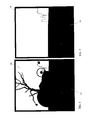
- FIG. 8 illustrates an example of another element (e.g., the tree element) that has been segmented and isolated.
- FIG. 9 illustrates reconstruction of the segmented element of FIG. 8 .
- FIG. 10 illustrates segmentation and isolation of another segmented and isolated element (e.g., the fence element).
- FIG. 11 illustrates reconstruction of the element of FIG. 10 .
- FIG. 12 illustrates yet another element (e.g. the lens flare element) after it has been segmented and isolated.
- FIG. 13 illustrates reconstruction of the segmented element of FIG. 12 .
- FIG. 13 further illustrates use of an embodiment of an alpha channel that is used to reintroduce transparency to elements with inherent transparency or translucency (e.g., the lens flare element).
- FIG. 14A is an illustration of an original monoscopic image that is the left eye view in a pair of stereoscopic images.
- FIG. 14B is an illustration of one embodiment of a re-composited and converted image that is the right eye view in the pair of stereoscopic images.
- FIG. 15A is an illustration of one embodiment of the original monoscopic image that is the left eye view in a pair of stereoscopic images of FIG. 14A , with transparency in the lens flare element.
- FIG. 15B is an illustration of the one embodiment of the re-composited and converted image that is the right eye view in the pair of stereoscopic images of FIG. 14B , with transparency in the lens flare element.
- FIG. 16 is an illustration of a three-quarters view of the scene, depicted in the original monoscopic image of FIG. 2 , after it has been composited without being prepared through the techniques introduced in the present application.
- FIG. 17 is a three-quarters view of the scene, depicted in the original monoscopic image of FIG. 1 , after it has been composited and prepared using the techniques introduced herein.
- 2D image, two-dimensional image, and monoscopic image all refer to an image that was captured with the original intention of presentation through a single perspective or view.
- 3D image, S3D image, three-dimensional image or a stereoscopic image refers to an image pair in which one eye is focused on one of the images of the pair and the other eye focuses on the second image of the pair.
- the stereoscopic image pair may be captured by an actual dual camera setup, a synthetic dual camera setup, or may be generated from a monoscopic image source through various 2D to 3D conversion methods.
- 2D to 3D image conversion refers to the process in which a 2D image is modified or manipulated in order to create a complementary stereoscopically paired image or create a plurality of stereoscopically paired images.
- Compositing refers to the digital method of combining two or more images using operating scripts based off of mathematical expressions.
- image sequence is broadly defined to include a series of individual images that when played in order, create a motion picture.
- Image sequences can be stored analog on film strips and/or may be processed into a computer as image sequence container files or as individually numbered images that can be imported in order to create an image sequence.
- 2.5D is broadly defined to include images or processes that exhibit some but not all three dimensional properties. When used in a specific manner, 2.5D images or processes can give the illusion of being fully three dimensional.
- alpha is broadly defined to include the transparency information of an image.
- an alpha channel can be represented as an embedded data channel in a digital file or a separate grayscale raster image.
- RGB is broadly defined to include image data that is encoded to create a visual record file that maintains discrete records of each additive primary color channel: Red, Green, and Blue.
- RGBA refers to the same RGB record, with one additional “alpha” channel for transparency information.
- pre-composing is broadly defined to include performing a render operation specifically before taking the finished composite and composing it with another element. This order of operations prevents unintended compositing operations from being performed.
- pre-visualizing is broadly defined to include creating a proxy rendition of a final product, far before the final product is produced in order to get a rough idea of what the final product will look like and to make decisions about changes that could be much more costly near the final stages of final product completion.
- the term “ingesting” is broadly defined to include importing data into a pipeline, workflow, or process.
- re-compositing environment is broadly defined to include the structure and workflow in which the re-composite phase is being carried out.
- Example include a node based compositing system, a CG generation application, or a command line based encoder.
- the single still image may represent a sequence of images that would preferably be processed by the method of the present invention.
- the 2D to 3D conversion process is the act of creating two distinct perspective views of a recorded visual media from a single original perspective view of a recorded visual media. Parrallax is introduced in the process, and areas that could not be seen in the single original view are revealed after the process.
- the decomposite techniques introduced herein pre-treat these revealed surfaces by generating the revealed surface data while the image is still in 2D form.
- the process requires that elements within the recorded visual media that have distinct distances from the viewer of the recorded visual media are segmented and reconstructed, only to be composited back together procedurally prior to completion of the 2D to 3D conversion process.
- the method is tied to the 2D-3D conversion process in that it pre-processes or “prepares” input data fed into the conversion process, it is still procedurally distinct and independent from the 2D-3D conversion process.
- determining depth (implied or exact) of the various elements of an image is typically accomplished through an analysis of one or more depth cues.
- the depths cues include, but are not limited to: an atmospheric contrast; a volumetric light; a relative size of one or more objects in relation to a standard size of the one more objects; the relative size of the one or more objects in relation to the one or more objects proximity to a horizon; one or more foreground objects occluding one or more background objects; a relative speed of one or more moving objects over an equal distance; or a color, a shadow, and/or a lighting of the one or more objects.
- FIG. 1A is an exemplary flow diagram illustrating an exemplary embodiment of a method of preparing a two-dimensional image to be converted into a three-dimensional image.
- implementation of the method is accomplished by use of one or more computers. It is understood that some or all steps illustrated here are automatic (i.e., may be performed directly by the computer without any human intervention), while some steps may require at least some human intervention prior to or subsequent to completion of the step. Although the listed steps are preferred in one embodiment, it is not required that each and every step listed in FIG. 1 be practiced. Additionally, while the exemplary embodiment of FIG.
- FIG. 1 illustrates ingestion of a digital image or a digital image sequence into a computer.
- the sequence may be, for example, an originally digital file, an analog file, or a film strip that has been converted into a digital file.
- the input may also include multi-view assets received from various sources.
- a multi-view asset may already have “3D” information in them (e.g., through capture of information using 3D cameras), but such multi-view assets may still be incomplete or not have complete 3D occluded region information to be able to effectively placed in conjunction with other images in the sequence. Accordingly, if a multi-view asset is received, such an asset is converted to formats acceptable by the system described herein and further processing continues as with other non-multi-view assets.
- preliminary processes may need to be performed to ensure compliance or coordination with present processes.
- 3D elements may be teased out from the 2D elements.
- the 3D objects may have the following done to ensure that they match other 2D/3D properties: the objects may be reshaped, depth grading (or existing depth grade altered) may be performed to match depth grading trends of existing/processed assets, matching steps may be performed to match render aspect of the received assets with existing assets, etc.
- the conversion techniques illustrated herein cover not just 2D to 3D conversion, but also 3D to 3D conversion to ensure quality of final 3D product.
- the input image format may be inclusive of all types of formats as understood by a person of ordinary skill in the art, including formats such as the DEEP format.
- the generated 3D data may include the ability to develop multiple perspectives for specific displays such as an auto stereo screen.
- the method includes a step of estimating the image data that will be revealed after the 2D to 3D conversion process.
- the estimation of the occluded regions may be accomplished by known methods and systems, including, but not limited to pre-visualizing a partial or full 2D to 3D conversion of the original sequence of two-dimensional digital images and offsetting the one or more discrete elements accordingly.
- This step enables identification or estimation of occluded regions of interest. In this manner the occluded regions of the discrete elements may be reconstructed based on the pre-visualization estimation. The identified occluded regions are then fully or partially reconstructed, as may be necessitated on a case-by-case basis.
- the method progresses to block 30 , where the image (or image sequence as the case may be) is segmented, resulting in discrete elements as identified in blocks 40 .
- the segmentation step 30 is accomplished through known methods, including, but not limited to: rotoscoping the single two-dimensional digital image manually through an operator (or artist); rotoscoping the single two-dimensional digital image partially manually and partially automatically; procedural color keying luminance keying; procedural color keying color difference keying; selective image isolation through motion vector analysis; selective image isolation through planar tracking; or selective image isolation through camera solving.
- the segmented elements identified in block 40 may be isolated individually, as will further be illustrated in reference to FIGS. 4-12 below, in order to more easily reconstruct them. Subsequently, as illustrated in block 50 , each of the discrete elements may be reconstructed to generate segmented and reconstructed elements. Such reconstructed elements are illustrated in blocks 60 .
- such reconstruction may be performed using various known methods, including, but not limited to: a manual procedural painting; a manual non-procedural painting; a matte painting; a computer generated replacement via three-dimensional model; a computer generated replacement via two-dimensional model; a computer generated replacement via particle system; a computer generated replacement via procedural scripting; a camera tracking, nodal tracking, planar tracking, motion vector tracking, and matchmoving; a model; a partially automated inpainting; a partially automated image filtering system; a fully automated inpainting; a fully automated image filtering system; and/or a grain removal, matching, and creation system.
- the reconstructed elements identified in blocks 60 may be re-composited through know methods as is illustrated in block 70 .
- Re-composition may be performed using known processes, including but not limited to: Over; Add; Multiply; Divide; etc.
- Over is when one element is placed over another element.
- Add is when one element's characteristics are added to another element's.
- Multiply is when one element's characteristics are multiplied with another element's.
- Divide is when one element's characteristics is divided by another element's.
- the environment for re-compositing 70 of the reconstructed discrete elements 60 is preferably done in a known environment, including, but not limited to: a two-dimensional digital composite system; a two-and-a-half-dimensional (“2.5D”) digital composite system; a three-dimensional digital composite system; a two-dimensional digital cg model creation system; a 2.5D digital cg model creation system; a three-dimensional digital cg model creation system; a two-dimensional digital animation system; a 2.5D digital animation system; a three-dimensional digital animation system; a two-dimensional digital editing system; a 2.5D digital editing system; a three-dimensional digital editing system; a two-dimensional digital lighting system; a 2.5D digital lighting system; and/or a three-dimensional digital lighting system.
- a two-dimensional digital composite system including, but not limited to: a two-dimensional digital composite system; a two-and-a-half-dimensional (“2.5D”) digital composite system; a three-dimensional digital composite system; a two-dimensional digital c
- the above steps, covered approximately by blocks 10 through 70 illustrated an exemplary embodiment of the technique discussed herein to achieve the purpose of preparing a two-dimensional image prior to converting the two-dimensional image into a three-dimensional image.
- the above process may inherently be tied to and be part of an overall 2D-3D conversion process or may be procedurally isolated from such a 2D-3D conversion process.
- the segmented, reconstructed, and/or re-composited elements are then ingested into a 2D to 3D conversion process, as illustrated in block 80 .
- the 2D-3D conversion process of block 80 generates a stereoscopic image pair of the original image.
- this conversion process may be accomplished through various known methods, including, but not limited to: two-dimensional image modifications driven by three-dimensional geometry manipulation systems; two-dimensional image modifications driven by two-dimensional depth map systems; two-dimensional image modifications driven by color or luminance systems; two-dimensional image modifications driven by two-dimensional warping and filtering systems; two-dimensional image manipulations driven by motion vector estimation systems; two-dimensional image manipulations driven by temporal estimation systems; three-dimensional modeling and texturing based off of camera tracking or solving systems; three-dimensional modeling and texturing systems; three-dimensional modeling and displacement systems; or three-dimensional modeling and/or projection systems.
- FIG. 1B and the following discussion now provide a brief, general description of a representative environment for practicing the techniques described, for example, in FIG. 1 .
- aspects of the invention may be described below in the general context of computer-executable instructions, such as routines executed by a general-purpose data processing device (e.g., a server computer or a personal computer).
- a general-purpose data processing device e.g., a server computer or a personal computer.
- PDAs personal digital assistants
- the invention can be practiced with other communications, data processing, or computer system configurations, including: wireless devices, Internet appliances, hand-held devices (including personal digital assistants (PDAs)), all manner of cellular or mobile phones, multi-processor systems, microprocessor-based or programmable consumer electronics, set-top boxes, network PCs, mini-computers, mainframe computers, and the like.
- PDAs personal digital assistants
- the terms “computer,” “server,” and the like are used interchangeably herein, and may refer to any of the above devices and systems. While aspects of the invention, such as certain functions, are described as being performed exclusively on a single device, the invention can also be practiced in distributed environments where functions or modules are shared among disparate processing devices.
- the disparate processing devices are linked through a communications network, such as a Local Area Network (LAN), Wide Area Network (WAN), or the Internet.
- LAN Local Area Network
- WAN Wide Area Network
- program modules may be located in both local and remote memory storage devices.
- aspects of the invention may be stored or distributed on tangible computer-readable media, including magnetically or optically readable computer discs, hard-wired or preprogrammed chips (e.g., EEPROM semiconductor chips), nanotechnology memory, biological memory, or other data storage media.
- computer implemented instructions, data structures, screen displays, and other data related to the invention may be distributed over the Internet or over other networks (including wireless networks), on a propagated signal on a propagation medium (e.g., an electromagnetic wave(s), a sound wave, etc.) over a period of time.
- the data may be provided on any analog or digital network (packet switched, circuit switched, or other scheme).
- a 3D server 1120 may be utilized for performing the various functions described with reference to FIG. 1A .
- the 3D server 1120 may include a computation block, 3D comp 1175 , that includes a plurality of modules for performing one or more of the described functions.
- the 3D comp block 1175 can be implemented by using programmable circuitry programmed by software and/or firmware, or by using special-purpose hardwired circuitry, or by using a combination of such embodiments.
- the computation subsystem 860 is implemented as a logical or functional unit in a processor of the 3D server 1120 .
- the ingest module 1175 performs, for example, the above described functions associated with block 10 of FIG. 1A .
- the estimation module 1175 B performs estimation of eventual 3D rendering as described with reference to block 20 of FIG. 1A .
- the segmentation module 1175 C performs functions associated with segmenting the various elements of a 2D image, described for example with reference to block 30 of FIG. 1A .
- the reconstruction module 1175 D implements routines and algorithms related to reconstruction of occluded regions, as described with reference to block 50 of FIG. 1A .
- the recomposition module 1175 E performs various functions associated with reconstruction of a 2D image after reconstruction is done, as described above with reference to block 70 of FIG. 1A .
- the 3D conversion module 1175 F is associated with the actual 2D to 3D conversion processes, the functions of which, while being a part of a 3D conversion process, are still ancillary to the decomposition and 2D image preparation techniques discussed herein.
- clients 1130 A and 1130 B may communicate with the 3D server 1120 to access the 3D Comp 1175 computational resources to perform one or more functions related to preparing the 2D image.
- the clients may themselves have inbuilt 3D blocks for performing the various functions.
- the distributed computers may, in embodiments, communicate over a communication network 1110 .
- the network 1110 may be, for example, an internal network specific to an organization or the Internet.
- the image content is available to the distributed network or the individual computing devices from a content storage repository 1180 accessible over the network 1110 .
- the various computational modules are completely automatic or sequential in operation.
- an operator may utilize automated routines of the estimation module 1175 B, to determine regions that will be likely revealed during a 3D conversion process.
- the segmentation module may still be performed using computing routines offered by the segmentation module 1175 C, the operator may need to manually operate on the images using tools offered by the segmentation module 1175 C to carve out and isolate various segments of the images.
- the segmentation module 1175 C may automatically identify such segments without any human intervention.
- the 3D comp block 1175 described herein may only contain blocks 1175 A through 1175 E, leaving out the actual 2D-3D conversion process to be done at different machines or different computing mechanisms.
- computational sub-blocks of 3D comp 1175 are not necessarily discrete elements, and that the elements may all be combined as a single or multiple computational blocks capable of providing and enabling software routines that enable an operator to perform the various tasks of preparing a 2D image as described herein.
- FIG. 1C is a high-level block diagram showing an example of the architecture for a computer system 600 that can be utilized to implement a 3D server 1120 , a client 1130 A, or any computer or computers that may be utilized for performing the various functions described herein.
- the computer system 600 includes one or more processors 605 and memory 610 connected via an interconnect 625 .
- the interconnect 625 is an abstraction that represents any one or more separate physical buses, point to point connections, or both connected by appropriate bridges, adapters, or controllers.
- the interconnect 625 may include, for example, a system bus, a Peripheral Component Interconnect (PCI) bus, a HyperTransport or industry standard architecture (ISA) bus, a small computer system interface (SCSI) bus, a universal serial bus (USB), IIC (I2C) bus, or an Institute of Electrical and Electronics Engineers (IEEE) standard 694 bus, sometimes referred to as “Firewire.”
- PCI Peripheral Component Interconnect
- ISA HyperTransport or industry standard architecture
- SCSI small computer system interface
- USB universal serial bus
- I2C IIC
- IEEE Institute of Electrical and Electronics Engineers
- the processor(s) 605 may include central processing units (CPUs) to control the overall operation of, for example, the host computer. In certain embodiments, the processor(s) 605 accomplish this by executing software or firmware stored in memory 610 .
- the processor(s) 605 may be, or may include, one or more programmable general-purpose or special-purpose microprocessors, digital signal processors (DSPs), programmable controllers, application specific integrated circuits (ASICs), programmable logic devices (PLDs), or the like, or a combination of such devices.
- the memory 610 is or includes the main memory of the computer system 1100 .
- the memory 610 represents any form of random access memory (RAM), read-only memory (ROM), flash memory (as discussed above), or the like, or a combination of such devices.
- the memory 610 may contain, among other things, a set of machine instructions which, when executed by processor 605 , causes the processor 605 to perform operations to implement embodiments of the present invention.
- Also connected to the processor(s) 605 through the interconnect 625 is a network adapter 615 .
- the network adapter 615 provides the computer system 600 with the ability to communicate with remote devices, such as the storage clients, and/or other storage servers, and may be, for example, an Ethernet adapter or Fiber Channel adapter.
- FIG. 2 now illustrates an example of an original monoscopic image that is to be prepared for a two-dimensional to three-dimensional conversion process.
- FIG. 2 illustrates how an image may contain many discrete elements.
- the sky 100 and house 110 are background elements.
- the ground 120 is a mid-ground element, and the lens flare 150 , tree 130 , and fence 160 are foreground elements. These discrete elements are isolated from each other during the segmentation process explained above with respect to FIGS. 1A and 1B .
- FIG. 3 illustrates an exemplary embodiment of a complementary image created from the original monoscopic image of FIG. 2 as a result of a 2D to 3D conversion process.
- FIG. 3 depicts how the discrete elements in the original monoscopic image of FIG. 2 have shifted at varying distances horizontally (relative to the image in FIG. 2 ) depending on the relative depth of the element in the original FIG. 2 image.
- the lens flare 150 , 151 , 152 , 153 and 154 , tree 130 , and fence 160 are the elements closest to the viewer, so their horizontal shift is greater than that of the background elements sky 100 and house 110 .
- FIG. 1 illustrates an exemplary embodiment of a complementary image created from the original monoscopic image of FIG. 2 as a result of a 2D to 3D conversion process.
- FIG. 3 depicts how the discrete elements in the original monoscopic image of FIG. 2 have shifted at varying distances horizontally (relative to the image in FIG. 2 ) depending on the relative depth of the element in
- FIG. 3 also illustrates how the creation of the complementary image reveals newly visible areas on some of the elements that were formerly occluded by the original placement of other discrete elements.
- These occluded areas, or artifacts of the 2D to 3D conversion process, 200 are shown in FIG. 3 as black solids, because the image data is missing. The artifacts must have the image data reconstructed so that the alternate image can be complete and not be distracting to the viewer.
- the images in FIGS. 2 and 3 would form a pair of images that can present the viewer with a stereoscopic perspective.
- FIG. 3 represents a prior art scenario where the complementary image is created after it has been processed in 2D to 3D conversion.
- This image can be viewed in tandem with the original image to form a stereoscopic image pair, but the stereoscopic view suffers from distracting artifacts in the complementary view.
- the artifacts are missing image data revealed as a concomitant problem with the 2D to 3D conversion process.
- the arrows 200 in FIG. 3 point to blank portions of the image that were occluded in the original image and are now revealed by the 2D to 3D conversion process.
- This image, as illustrated in FIG. 3 has not been through the preparation method of the present invention, so the correct image data is not available for the occluded areas and they have been filled with a solid color.
- FIG. 4 now illustrates a scenario that utilizes the techniques of the present application.
- FIG. 4 depicts an example of an element (e.g., the “sky” element 100 ) that has been segmented and isolated from the original monoscopic image (e.g., as a result of the segmentation process 30 of FIG. 1A ).
- FIG. 4 shows in white the isolated and segmented sky element 100 .
- the other elements 101 some of which occlude portions of the sky 100 , are shown as blank.
- the blankness of the other elements 101 is temporary and allows the sky 100 to be shown as isolated so that it can be reconstructed more easily.
- FIG. 5 illustrates an example of reconstruction of a segmented element (e.g., the sky element).
- FIG. 5 illustrates how the sky element is reconstructed to create the reconstructed sky element 102 .
- the remainder of the image 103 is shown as temporarily blank.
- the sky element is preferably reconstructed based on contextual information within the scene, such as the orientation of the clouds and the general uniformity in the texture of the sky itself.
- FIG. 5 shows that the entire sky above the ground is fully reconstructed, preferably, the reconstruction is only carried out as much as is needed based on the estimations of how much newly visible matter of the element will be shown after the offset during the 2D to 3D process.
- Estimations can be carried out by setting up offset values ahead of the reconstruction step, by pre-visualizing a partial or full 2D to 3D conversion of the monoscopic original image, and/or by attempting to reconstruct all portions of the element that were occluded.
- FIG. 6 illustrates an example where two elements (e.g., a house element 110 and a ground element 120 ) are segmented and isolated together as one element.
- the decision to segment the house 110 and the ground 120 together is based on the fact that the house 110 does not directly occlude any portion of the ground 120 that would be revealed as a result of the 2D to 3D conversion process.
- FIG. 7 now illustrates reconstruction of the segmented house and ground elements.
- FIG. 7 illustrates a scenario where the reconstructed house 111 has been reconstructed based on other images of the house, contextual data, and even assumptions, such as assuming that the house is symmetrical. Additionally, FIG. 7 shows that the reconstructed ground 121 has been reconstructed based on contextual image data and now the path 122 to the house 111 is revealed.
- FIG. 8 is an illustration of segmentation and isolation of the tree element 130 .
- FIG. 8 shows the tree element 130 as an isolated and segmented element.
- FIG. 9 is illustrated reconstruction of the segmented tree element 130 .
- FIG. 9 shows that the reconstructed tree 131 has a trunk from the ground all the way to the branches. This is a further example of reconstruction through context and assumption.
- FIG. 10 is an illustration of segmentation and isolation of the fence element.
- FIG. 10 shows fence element 160 as an isolated and segmented element.
- FIG. 11 is an illustration of one embodiment of the reconstructed and segmented fence element.
- the reconstructed fence 161 is now completely visible.
- FIG. 12 is an illustration of the lens Flare element after it has been segmented and isolated.
- the lens flare 150 , 151 , 152 , 153 and 154 is a scattered element.
- the lens flare 150 , 151 , 152 , 153 and 154 is not occluded by any other element, it still needs to be reconstructed because the segmenting process may require that a previously transparent or semi-transparent element be turned into an opaque element. In embodiments, this may be accomplished by extracting the lens flare 150 , 151 , 152 , 153 and 154 by means of, for example, an image keyer, and then removing any traces of the background image data using digital paint or color correction techniques.
- elements such as the lens flare 150 , 151 , 152 , 153 and 154 can be recreated from scratch as an opaque element.
- the lens flare 150 , 151 , 152 , 153 and 154 shown in FIG. 12 is opaque. As such, the lens flare 150 , 151 , 152 , 153 and 154 , after isolation and segmentation, needs to be reconstructed as a transparent element.
- FIG. 13 illustrates reconstruction of the segmented element of FIG. 12 .
- FIG. 13 further illustrates use of an embodiment of an alpha channel that is used to reintroduce transparency to elements with inherent transparency or translucency (e.g., the lens flare element).
- FIG. 13 displays the alpha channel that will be used to re-introduce transparency into the solid color of the recreated Lens Flare.
- the lens flare 250 , 251 , 252 , 253 and 254 has been reconstructed as a gradated discrete element, representing the understood transparency of the lens flare element in FIG. 12 .
- This element is known as an alpha channel.
- Alpha channels determine the transparency of an element, which in turn helps determine the appearance of the element when used in a composite.
- An alpha channel is represented as a grayscale image, where pure black represents full transparency (meaning no color data is sampled from the associated RGB channels), and pure white represents full opaqueness (meaning the complete color data is shown from the associated RGB channels). Shades of gray in between represent varying degrees of transparent RGB data.
- FIG. 14A is an illustration of an original monoscopic image that is the left eye view in a pair of stereoscopic images.
- FIG. 14A shows that one of the stereoscopic views may be the original monoscopic image, which is also shown in FIG. 2 , the stereoscopic views may both be alternative images that have been through the preparation method discussed herein and the two-dimensional to three-dimensional conversion process.
- FIG. 14B is an illustration of one embodiment of a re-composited and converted image that is the right eye view in the pair of stereoscopic images.
- FIG. 14B displays the reconstructed, re-composited, and converted complementary perspective image as the right side image.
- the left image, shown in FIG. 14A is intended to be viewed only with the left eye
- the right image, shown in FIG. 14B is intended to only be viewed with the right eye.
- previously occluded regions of the original image, shown in FIG. 14A are now visible and accurately reconstructed.
- An example of the previously occluded, and now visible and accurately reconstructed region is area 400 .
- Area 400 is the window of the house that is now visible. In this illustration, the window has been accurately reconstructed through the preparation process discussed herein, thus allowing the 2D to 3D conversion process to be accomplished much more efficiently, easily, and accurately.
- FIG. 15A illustrates an exemplary embodiment of the original monoscopic image that is the left eye view in a pair of stereoscopic images of FIG. 14A , with transparency in the lens flare element.
- FIGS. 15A and 15B display the same results, but with the addition of transparency in the Lens Flare element.
- FIG. 16 is a three-quarters view of the scene depicted in the original monoscopic image shown in FIG. 2 after it has been composited without being prepared using the techniques discussed introduced in the present application.
- FIG. 16 displays a three-quarters perspective view of the original image with the discrete image elements, including lens flare 150 , tree 130 , and fence 160 , isolated and segmented for the purpose of 2D to 3D conversion. But, the image in FIG. 16 did not undergo the “preparation” process of the present application. Consequently, the occluded areas 600 in FIG. 16 are not reconstructed.
- the occluded areas 600 would now need to be filled with image data, but because the two monoscopic images have a stereoscopic relationship, discretion must be taken to not adversely affect the stereoscopic discrepancies that have been precisely and carefully introduced between the two views. This process would require special tools and skills, and would consequently require a relatively exorbitant input of time and effort to bring to precision.
- Such a disadvantage of the prior art methodology of 2D to 3D conversion can be overcome by practicing the “preparation” process introduced herein.
- FIG. 17 is a three-quarters view of the scene, depicted in the original monoscopic image of FIG. 2 after the image has been composited and prepared using the techniques described herein.
- FIG. 17 displays a three-quarter perspective view of the reconstructed elements, including house 111 , tree 131 , and fence 161 , being re-composited in order to be ingested in that state into the 2D to 3D conversion process. Because the file was previously prepared using the techniques described, for example, with respect to FIG. 1A , the occluded areas already contain correct image data, requiring no additional work in order to output a complete and accurate stereoscopic image pair after a 2D to 3D conversion.
- the words “comprise,” “comprising,” and the like are to be construed in an inclusive sense (i.e., to say, in the sense of “including, but not limited to”), as opposed to an exclusive or exhaustive sense.
- the terms “connected,” “coupled,” or any variant thereof means any connection or coupling, either direct or indirect, between two or more elements. Such a coupling or connection between the elements can be physical, logical, or a combination thereof.
- the words “herein,” “above,” “below,” and words of similar import when used in this application, refer to this application as a whole and not to any particular portions of this application.
- words in the above Detailed Description using the singular or plural number may also include the plural or singular number respectively.
- the word “or,” in reference to a list of two or more items, covers all of the following interpretations of the word: any of the items in the list, all of the items in the list, and any combination of the items in the list.
Abstract
Description
-
- U.S. Pat. No. 7,116,324, titled “Method for Minimizing Visual Artifacts Converting Two-Dimensional Motion Pictures into Three-Dimensional Motion Pictures,” issued on Oct. 3, 2006.
- U.S. Pat. No. 7,116,323, titled “Method of Hidden Surface Reconstruction for Creating Accurate Three-Dimensional Images Converted from Two-Dimensional Images,” issued on Oct. 3, 2006.
- U.S. Pat. No. 7,102,633, titled “Method for Conforming Objects to Common Depth Perspective for Converting Two-Dimensional Images into Three-Dimensional Images,” issued on Sep. 5, 2006.
- U.S. Pat. No. 6,686,926, titled “Image Processing System and Method for Converting Two-Dimensional Images into Three-Dimensional Images,” issued on Feb. 3, 2004.
- U.S. Pat. No. 6,515,659, titled “Method and System for Creating Realistic Smooth Three-Dimensional Depth Contours from Two-Dimensional Images,” issued on Feb. 4, 2003.
- U.S. Pat. No. 6,208,348, titled “System and Method for Dimensionalization Processing of Images in Consideration of a Predetermined Image Projection Format,” issued on Mar. 27, 2001.
Claims (50)
Priority Applications (1)
| Application Number | Priority Date | Filing Date | Title |
|---|---|---|---|
| US13/230,750 US8831273B2 (en) | 2010-09-10 | 2011-09-12 | Methods and systems for pre-processing two-dimensional image files to be converted to three-dimensional image files |
Applications Claiming Priority (2)
| Application Number | Priority Date | Filing Date | Title |
|---|---|---|---|
| US38189410P | 2010-09-10 | 2010-09-10 | |
| US13/230,750 US8831273B2 (en) | 2010-09-10 | 2011-09-12 | Methods and systems for pre-processing two-dimensional image files to be converted to three-dimensional image files |
Publications (2)
| Publication Number | Publication Date |
|---|---|
| US20120106785A1 US20120106785A1 (en) | 2012-05-03 |
| US8831273B2 true US8831273B2 (en) | 2014-09-09 |
Family
ID=45996810
Family Applications (1)
| Application Number | Title | Priority Date | Filing Date |
|---|---|---|---|
| US13/230,750 Active 2032-12-24 US8831273B2 (en) | 2010-09-10 | 2011-09-12 | Methods and systems for pre-processing two-dimensional image files to be converted to three-dimensional image files |
Country Status (1)
| Country | Link |
|---|---|
| US (1) | US8831273B2 (en) |
Cited By (2)
| Publication number | Priority date | Publication date | Assignee | Title |
|---|---|---|---|---|
| US20140223308A1 (en) * | 2013-02-04 | 2014-08-07 | Visible Spectrum, Inc. | Network Based Video Creation |
| US20140362076A1 (en) * | 2001-10-11 | 2014-12-11 | Pure Depth Limited | Display interposing a physical object within a three-dimensional volumetric space |
Families Citing this family (11)
| Publication number | Priority date | Publication date | Assignee | Title |
|---|---|---|---|---|
| US8773507B2 (en) * | 2009-08-11 | 2014-07-08 | California Institute Of Technology | Defocusing feature matching system to measure camera pose with interchangeable lens cameras |
| WO2014145722A2 (en) * | 2013-03-15 | 2014-09-18 | Digimarc Corporation | Cooperative photography |
| CA2820305A1 (en) | 2013-07-04 | 2015-01-04 | University Of New Brunswick | Systems and methods for generating and displaying stereoscopic image pairs of geographical areas |
| US9390328B2 (en) * | 2014-04-25 | 2016-07-12 | Xerox Corporation | Static occlusion handling using directional pixel replication in regularized motion environments |
| US11550387B2 (en) * | 2015-03-21 | 2023-01-10 | Mine One Gmbh | Stereo correspondence search |
| EP3274986A4 (en) * | 2015-03-21 | 2019-04-17 | Mine One GmbH | Virtual 3d methods, systems and software |
| KR101784611B1 (en) * | 2016-06-09 | 2017-11-06 | 재단법인대구경북과학기술원 | A human detecting apparatus and method using a lidar sensor and a radar sensor |
| CN109658517B (en) * | 2018-12-20 | 2023-01-24 | 广东精鹰传媒集团股份有限公司 | Implementation method for generating three-dimensional visual effect by two-dimensional arrow diagram in virtual environment |
| CN110070595B (en) * | 2019-04-04 | 2020-11-24 | 东南大学深圳研究院 | Single image 3D object reconstruction method based on deep learning |
| US11010984B2 (en) * | 2019-06-05 | 2021-05-18 | Sagan Works, Inc. | Three-dimensional conversion of a digital file spatially positioned in a three-dimensional virtual environment |
| KR102441171B1 (en) * | 2020-05-26 | 2022-09-08 | 한국전자통신연구원 | Apparatus and Method for Monitoring User based on Multi-View Face Image |
Citations (26)
| Publication number | Priority date | Publication date | Assignee | Title |
|---|---|---|---|---|
| WO1997024000A1 (en) | 1995-12-22 | 1997-07-03 | Xenotech Research Pty. Ltd. | Image conversion and encoding techniques |
| WO1999012127A1 (en) | 1997-09-02 | 1999-03-11 | Dynamic Digital Depth Research Pty Ltd | Image processing method and apparatus |
| WO1999030280A1 (en) | 1997-12-05 | 1999-06-17 | Dynamic Digital Depth Research Pty. Ltd. | Improved image conversion and encoding techniques |
| WO2000079781A1 (en) | 1999-06-17 | 2000-12-28 | Dynamic Digital Depth Research Pty Ltd. | Image enhancement system |
| WO2001001348A1 (en) | 1999-06-25 | 2001-01-04 | Dynamic Digital Depth Research Pty Ltd. | Image conversion and encoding techniques |
| US6208348B1 (en) | 1998-05-27 | 2001-03-27 | In-Three, Inc. | System and method for dimensionalization processing of images in consideration of a pedetermined image projection format |
| US6215516B1 (en) | 1997-07-07 | 2001-04-10 | Reveo, Inc. | Method and apparatus for monoscopic to stereoscopic image conversion |
| WO2002013143A1 (en) | 2000-08-04 | 2002-02-14 | Dynamic Digital Depth Research Pty Ltd. | Image conversion and encoding technique |
| US20020048395A1 (en) | 2000-08-09 | 2002-04-25 | Harman Philip Victor | Image conversion and encoding techniques |
| US20020063780A1 (en) | 1998-11-23 | 2002-05-30 | Harman Philip Victor | Teleconferencing system |
| US20020075384A1 (en) | 1997-11-21 | 2002-06-20 | Dynamic Digital Depth Research Pty. Ltd. | Eye tracking apparatus |
| US6456340B1 (en) | 1998-08-12 | 2002-09-24 | Pixonics, Llc | Apparatus and method for performing image transforms in a digital display system |
| US6492986B1 (en) | 1997-06-02 | 2002-12-10 | The Trustees Of The University Of Pennsylvania | Method for human face shape and motion estimation based on integrating optical flow and deformable models |
| US6515662B1 (en) | 1998-07-16 | 2003-02-04 | Canon Kabushiki Kaisha | Computer apparatus for providing stereoscopic views from monographic images and method |
| US6515659B1 (en) | 1998-05-27 | 2003-02-04 | In-Three, Inc. | Method and system for creating realistic smooth three-dimensional depth contours from two-dimensional images |
| US6535233B1 (en) | 1998-11-20 | 2003-03-18 | International Business Machines Corporation | Method and apparatus for adjusting the display scale of an image |
| US6590573B1 (en) | 1983-05-09 | 2003-07-08 | David Michael Geshwind | Interactive computer system for creating three-dimensional image information and for converting two-dimensional image information for three-dimensional display systems |
| US6650339B1 (en) | 1996-08-02 | 2003-11-18 | Autodesk, Inc. | Three dimensional modeling and animation system |
| US20040004616A1 (en) | 2002-07-03 | 2004-01-08 | Minehiro Konya | Mobile equipment with three dimensional display function |
| US6677944B1 (en) | 1998-04-14 | 2004-01-13 | Shima Seiki Manufacturing Limited | Three-dimensional image generating apparatus that creates a three-dimensional model from a two-dimensional image by image processing |
| US6765568B2 (en) | 2000-06-12 | 2004-07-20 | Vrex, Inc. | Electronic stereoscopic media delivery system |
| US6791542B2 (en) | 2002-06-17 | 2004-09-14 | Mitsubishi Electric Research Laboratories, Inc. | Modeling 3D objects with opacity hulls |
| US6798406B1 (en) | 1999-09-15 | 2004-09-28 | Sharp Kabushiki Kaisha | Stereo images with comfortable perceived depth |
| US7102633B2 (en) | 1998-05-27 | 2006-09-05 | In-Three, Inc. | Method for conforming objects to a common depth perspective for converting two-dimensional images into three-dimensional images |
| US7116324B2 (en) | 1998-05-27 | 2006-10-03 | In-Three, Inc. | Method for minimizing visual artifacts converting two-dimensional motion pictures into three-dimensional motion pictures |
| US7116323B2 (en) | 1998-05-27 | 2006-10-03 | In-Three, Inc. | Method of hidden surface reconstruction for creating accurate three-dimensional images converted from two-dimensional images |
-
2011
- 2011-09-12 US US13/230,750 patent/US8831273B2/en active Active
Patent Citations (29)
| Publication number | Priority date | Publication date | Assignee | Title |
|---|---|---|---|---|
| US6590573B1 (en) | 1983-05-09 | 2003-07-08 | David Michael Geshwind | Interactive computer system for creating three-dimensional image information and for converting two-dimensional image information for three-dimensional display systems |
| WO1997024000A1 (en) | 1995-12-22 | 1997-07-03 | Xenotech Research Pty. Ltd. | Image conversion and encoding techniques |
| EP1187494A2 (en) | 1995-12-22 | 2002-03-13 | Dynamic Digital Depth Research Pty. Ltd. | Image conversion and encoding techniques |
| US6650339B1 (en) | 1996-08-02 | 2003-11-18 | Autodesk, Inc. | Three dimensional modeling and animation system |
| US6492986B1 (en) | 1997-06-02 | 2002-12-10 | The Trustees Of The University Of Pennsylvania | Method for human face shape and motion estimation based on integrating optical flow and deformable models |
| US6215516B1 (en) | 1997-07-07 | 2001-04-10 | Reveo, Inc. | Method and apparatus for monoscopic to stereoscopic image conversion |
| WO1999012127A1 (en) | 1997-09-02 | 1999-03-11 | Dynamic Digital Depth Research Pty Ltd | Image processing method and apparatus |
| US6496598B1 (en) | 1997-09-02 | 2002-12-17 | Dynamic Digital Depth Research Pty. Ltd. | Image processing method and apparatus |
| US20020075384A1 (en) | 1997-11-21 | 2002-06-20 | Dynamic Digital Depth Research Pty. Ltd. | Eye tracking apparatus |
| WO1999030280A1 (en) | 1997-12-05 | 1999-06-17 | Dynamic Digital Depth Research Pty. Ltd. | Improved image conversion and encoding techniques |
| US6677944B1 (en) | 1998-04-14 | 2004-01-13 | Shima Seiki Manufacturing Limited | Three-dimensional image generating apparatus that creates a three-dimensional model from a two-dimensional image by image processing |
| US6686926B1 (en) | 1998-05-27 | 2004-02-03 | In-Three, Inc. | Image processing system and method for converting two-dimensional images into three-dimensional images |
| US7116323B2 (en) | 1998-05-27 | 2006-10-03 | In-Three, Inc. | Method of hidden surface reconstruction for creating accurate three-dimensional images converted from two-dimensional images |
| US7116324B2 (en) | 1998-05-27 | 2006-10-03 | In-Three, Inc. | Method for minimizing visual artifacts converting two-dimensional motion pictures into three-dimensional motion pictures |
| US6515659B1 (en) | 1998-05-27 | 2003-02-04 | In-Three, Inc. | Method and system for creating realistic smooth three-dimensional depth contours from two-dimensional images |
| US6208348B1 (en) | 1998-05-27 | 2001-03-27 | In-Three, Inc. | System and method for dimensionalization processing of images in consideration of a pedetermined image projection format |
| US7102633B2 (en) | 1998-05-27 | 2006-09-05 | In-Three, Inc. | Method for conforming objects to a common depth perspective for converting two-dimensional images into three-dimensional images |
| US6515662B1 (en) | 1998-07-16 | 2003-02-04 | Canon Kabushiki Kaisha | Computer apparatus for providing stereoscopic views from monographic images and method |
| US6456340B1 (en) | 1998-08-12 | 2002-09-24 | Pixonics, Llc | Apparatus and method for performing image transforms in a digital display system |
| US6535233B1 (en) | 1998-11-20 | 2003-03-18 | International Business Machines Corporation | Method and apparatus for adjusting the display scale of an image |
| US20020063780A1 (en) | 1998-11-23 | 2002-05-30 | Harman Philip Victor | Teleconferencing system |
| WO2000079781A1 (en) | 1999-06-17 | 2000-12-28 | Dynamic Digital Depth Research Pty Ltd. | Image enhancement system |
| WO2001001348A1 (en) | 1999-06-25 | 2001-01-04 | Dynamic Digital Depth Research Pty Ltd. | Image conversion and encoding techniques |
| US6798406B1 (en) | 1999-09-15 | 2004-09-28 | Sharp Kabushiki Kaisha | Stereo images with comfortable perceived depth |
| US6765568B2 (en) | 2000-06-12 | 2004-07-20 | Vrex, Inc. | Electronic stereoscopic media delivery system |
| WO2002013143A1 (en) | 2000-08-04 | 2002-02-14 | Dynamic Digital Depth Research Pty Ltd. | Image conversion and encoding technique |
| US20020048395A1 (en) | 2000-08-09 | 2002-04-25 | Harman Philip Victor | Image conversion and encoding techniques |
| US6791542B2 (en) | 2002-06-17 | 2004-09-14 | Mitsubishi Electric Research Laboratories, Inc. | Modeling 3D objects with opacity hulls |
| US20040004616A1 (en) | 2002-07-03 | 2004-01-08 | Minehiro Konya | Mobile equipment with three dimensional display function |
Non-Patent Citations (28)
| Title |
|---|
| Allchin, James Edward, "An Architecture for Reliable Decentralized Systems," Ph.D. Thesis, Georgia Institute of Technology, 185 pages, Sep. 1983. |
| Augun Audrey, "Integrating Lotus Notes With Enterprise Data," Lotus Notes Advisory, pp. 22-25, Jul.-Aug. 1996. |
| Brinkmann, Ron, "The Art and Science of Digital Compositing," Second Edition, Elsevier Inc., Burlington, MA, 2008, pp. 1-14, 39-51, 93-231, 428-435, 605-625. |
| Co-pending U.S. Appl. No. 13/230,733, filed Sep. 12, 2011. |
| Finance, Charles et al., "The Visual Effects Producer Understanding the Art and Business of VFX," Elsevier Inc., Amsterdam: Boston, 2010, pp. 21-23, 37-52, 215-225, 241-248. |
| Gao, Qigang et al., Perceptual Motion Tracking from Image Sequences, IEEE, Jan. 2001, pp. 389-392. |
| Gleicher, Michael, "Image Snapping," SIGGRAPH: pp. 183-190, Jun. 1995. |
| Grossman, John, "Look Ma, No Glasses", Games, Apr. 1992, pp. 12-14. |
| Hanrahan, Pat et al., "Direct WYSIWYG painting and texturing on 3D shapes", Computer Graphics, vol. 24 Issues 4, pp. 215-223. Aug. 1990. |
| Izquierdo, Ebroul et al., Virtual 3D-View Generation from Stereoscopic Video Data, IEEE, Jan. 1998, pp. 1219-1224. |
| Kaufman, Debra, 3D Movie Magic Web Page Information, Jan. 21, 1998 The Big Picture, Web Page for Xenotech, Apr. 1998. |
| Kaufman, Debra, The Big Picture, Web Page for Xenotech, Apr. 1998, pp. 1-4 (downloaded Sep. 8, 1998). |
| Lipton, Lenny, "Foundation of The Stereoscopic Cinema A Study In Depth," Van Nostrand Reinhold Company Inc., New York, NY, 1982, pp. 53-90, 177-220. |
| Mae, Yasushi, et al., "Object Tracking in Cluttered Background Based on Optical Flow and Edges," Proc. 13th Int. Conf. on Pattern Recognition. vol. 1, pp. 196-200, Apr. 1996. |
| Mendiburu, Bernard, "3D Movie Making: Stereoscopic Digital Cinema From Script To Screen," Elsevier Inc., Burlington, MA, 2009, pp. 1-33, 47-71, 123-149, 171-196. |
| Mortensen, E.N. et al., "Intelligent Scissors for Image Composition," Computer Graphics (SIGGRAPH '95), pp. 191-198, Los Angeles, CA, Aug. 1995. |
| Mortensen, E.N. et al., "Interactive segmentation with Intelligent Scissors," Graphical Models and Image Processing, vol. 60 No. 5, pp. 349-384, Sep. 2002. |
| Murray et al., Active Tracking, IEEE International Conference on Intelligent Robots and Systems, Sep. 1993, pp. 1021-1028. |
| Nguyen, Hieu Tat et al., Tracking Nonparameterized Object Contours in Video, IEEE Transactions on Image Processing, vol. 11, No. 9, Sep. 2002, pp. 1081-1091. |
| Noll, Michael A., Computer-Generated Three-Dimensional Movies, Computers and Automation, vol. 14, No. 11 (Nov. 1965), pp. 20-23. |
| Noll, Michael A., Stereographic Projections by Digital Computer, Computers and Automation, vol. 14, No. 5 (May 1965), pp. 32-34. |
| Ohm et al., An Object-Based System for Stereoscopic Viewpoint Synthesis, IEEE transaction on Circuits and Systems for Video Technology, vol. 7, No. 5, Oct. 1997, pp. 801-811. |
| Okun, Jeffrey A., Susan Zwerman, eds., "The VES Handbook of Visual Effects: Industry Standard VFX Practices and Procedures," Elsevier Inc., Burlington, MA. 2010, pp. 1-14, 74-75, 222-232, 414-434, 550-574, 694-697. |
| Selsis et al., Automatic Tracking and 3D Localization of Moving Objects by Active Contour Models, Intelligent Vehicles 95 Symposium, Sep. 1995, pp. 96-100. |
| Slinker et al., "The Generation and Animation of Random Dot and Random Line Autostereograms". Journal of Imaging Science and Technology, vol. 36, No. 3, pp. 260-267, May 1992. |
| Weber, Joseph et al., "Rigid Body Segmentation and Shape Description from Dense Optical Flow Under Weak Perspective," IEEE Transactions on Pattern Analysis and Machine Intelligence, vol. 19, No. 2, Feb. 1997, pp. 139-143. |
| Wright, Steve, "Digital Compositing for Film and Video," Third Edition, Elsevier Inc., Burlington, MA, 2010, pp. 1-3, 103-110, 125-131, 153-156, 168-171. |
| Zhong, Di et al., "AMOS: An Active System for MPEG-4 Video Object Segmentation," ICIP (2) 8: pp. 647-651, Apr. 1998. |
Cited By (5)
| Publication number | Priority date | Publication date | Assignee | Title |
|---|---|---|---|---|
| US20140362076A1 (en) * | 2001-10-11 | 2014-12-11 | Pure Depth Limited | Display interposing a physical object within a three-dimensional volumetric space |
| US9721378B2 (en) * | 2001-10-11 | 2017-08-01 | Pure Depth Limited | Display interposing a physical object within a three-dimensional volumetric space |
| US10262450B2 (en) | 2001-10-11 | 2019-04-16 | Pure Depth Limited | Display interposing a physical object within a three-dimensional volumetric space |
| US20140223308A1 (en) * | 2013-02-04 | 2014-08-07 | Visible Spectrum, Inc. | Network Based Video Creation |
| US9110572B2 (en) * | 2013-02-04 | 2015-08-18 | Visible Spectrum, Inc. | Network based video creation |
Also Published As
| Publication number | Publication date |
|---|---|
| US20120106785A1 (en) | 2012-05-03 |
Similar Documents
| Publication | Publication Date | Title |
|---|---|---|
| US8831273B2 (en) | Methods and systems for pre-processing two-dimensional image files to be converted to three-dimensional image files | |
| US11721071B2 (en) | Methods and systems for producing content in multiple reality environments | |
| US10540806B2 (en) | Systems and methods for depth-assisted perspective distortion correction | |
| Bhat et al. | Using photographs to enhance videos of a static scene | |
| Harman et al. | Rapid 2D-to-3D conversion | |
| Smolic et al. | Three-dimensional video postproduction and processing | |
| US9699380B2 (en) | Fusion of panoramic background images using color and depth data | |
| Zhang et al. | 3D-TV content creation: automatic 2D-to-3D video conversion | |
| US9094675B2 (en) | Processing image data from multiple cameras for motion pictures | |
| US9485497B2 (en) | Systems and methods for converting two-dimensional images into three-dimensional images | |
| JP2001526477A (en) | Image conversion and coding technology | |
| Pearson et al. | Plenoptic layer-based modeling for image based rendering | |
| Ceulemans et al. | Robust multiview synthesis for wide-baseline camera arrays | |
| Jantet | Layered depth images for multi-view coding | |
| Jantet et al. | Joint projection filling method for occlusion handling in depth-image-based rendering | |
| Lu et al. | A survey on multiview video synthesis and editing | |
| WO2005034527A1 (en) | Stereoscopic imaging | |
| Loghman et al. | Segmentation-based view synthesis for multi-view video plus depth | |
| Evers‐Senne et al. | Image based interactive rendering with view dependent geometry | |
| Lipski et al. | Making of who cares? HD stereoscopic free viewpoint video | |
| Waschbüsch et al. | 3d video billboard clouds | |
| Sun et al. | Seamless view synthesis through texture optimization | |
| GB2543778A (en) | Systems and methods for processing images of objects | |
| Gunnewiek et al. | Coherent spatial and temporal occlusion generation | |
| Ebner et al. | Fully automated highly accurate 3D reconstruction from multiple views |
Legal Events
| Date | Code | Title | Description |
|---|---|---|---|
| AS | Assignment |
Owner name: DD3D, INC., FLORIDA Free format text: ASSIGNMENT OF ASSIGNORS INTEREST;ASSIGNOR:KARAFIN, JONATHAN;REEL/FRAME:027293/0066 Effective date: 20111122 |
|
| AS | Assignment |
Owner name: DIGITAL DOMAIN STEREO GROUP, INC., FLORIDA Free format text: CHANGE OF NAME;ASSIGNOR:DD3D, INC.;REEL/FRAME:027306/0167 Effective date: 20111129 |
|
| AS | Assignment |
Owner name: HUDSON BAY MASTER FUND LTD., AS COLLATERAL AGENT, Free format text: SECURITY AGREEMENT;ASSIGNORS:DIGITAL DOMAIN MEDIA GROUP, INC.;D2 SOFTWARE, INC.;DDH LAND HOLDINGS, LLC;AND OTHERS;REEL/FRAME:028833/0753 Effective date: 20120507 |
|
| AS | Assignment |
Owner name: REALD DDMG ACQUISITION, LLC, CALIFORNIA Free format text: ASSIGNMENT OF ASSIGNORS INTEREST;ASSIGNORS:DIGITAL DOMAIN MEDIA GROUP, INC.;DIGITAL DOMAIN STEREO GROUP, INC.;REEL/FRAME:029617/0396 Effective date: 20130111 |
|
| AS | Assignment |
Owner name: CITY NATIONAL BANK, CALIFORNIA Free format text: PATENT SECURITY AGREEMENT;ASSIGNOR:REALD DDMG ACQUISITION, LLC;REEL/FRAME:029855/0189 Effective date: 20130111 |
|
| STCF | Information on status: patent grant |
Free format text: PATENTED CASE |
|
| AS | Assignment |
Owner name: REALD DDMG ACQUISITION, LLC, CALIFORNIA Free format text: RELEASE FROM PATENT SECURITY AGREEMENT AT REEL/FRAME NO. 29855/0189;ASSIGNOR:CITY NATIONAL BANK;REEL/FRAME:038216/0933 Effective date: 20160322 |
|
| AS | Assignment |
Owner name: HIGHBRIDGE PRINCIPAL STRATEGIES, LLC, NEW YORK Free format text: SECURITY INTEREST;ASSIGNORS:REALD INC.;STEREOGRAPHICS CORPORATION;COLORLINK INC.;AND OTHERS;REEL/FRAME:038243/0526 Effective date: 20160322 |
|
| MAFP | Maintenance fee payment |
Free format text: PAYMENT OF MAINTENANCE FEE, 4TH YR, SMALL ENTITY (ORIGINAL EVENT CODE: M2551) Year of fee payment: 4 |
|
| AS | Assignment |
Owner name: JEFFERIES FINANCE LLC, AS COLLATERAL AGENT, NEW YORK Free format text: SECURITY INTEREST;ASSIGNORS:REALD INC.;RHOMBUS INTERMEDIATE HOLDINGS, LP;REALD HOLDINGS, INC;AND OTHERS;REEL/FRAME:047723/0767 Effective date: 20181130 Owner name: JEFFERIES FINANCE LLC, AS COLLATERAL AGENT, NEW YO Free format text: SECURITY INTEREST;ASSIGNORS:REALD INC.;RHOMBUS INTERMEDIATE HOLDINGS, LP;REALD HOLDINGS, INC;AND OTHERS;REEL/FRAME:047723/0767 Effective date: 20181130 |
|
| AS | Assignment |
Owner name: JEFFERIES FINANCE LLC, AS COLLATERAL AGENT, NEW YORK Free format text: SECURITY INTEREST;ASSIGNORS:REALD INC.;RHOMBUS INTERMEDIATE HOLDINGS, LP;REALD HOLDINGS, INC;AND OTHERS;REEL/FRAME:047740/0085 Effective date: 20181130 Owner name: JEFFERIES FINANCE LLC, AS COLLATERAL AGENT, NEW YO Free format text: SECURITY INTEREST;ASSIGNORS:REALD INC.;RHOMBUS INTERMEDIATE HOLDINGS, LP;REALD HOLDINGS, INC;AND OTHERS;REEL/FRAME:047740/0085 Effective date: 20181130 Owner name: REALD INC., CALIFORNIA Free format text: RELEASE BY SECURED PARTY;ASSIGNOR:HPS INVESTMENT PARTNERS, LLC, AS COLLATERAL AGENT;REEL/FRAME:047741/0621 Effective date: 20181130 Owner name: STEREOGRAPHICS CORPORATION, CALIFORNIA Free format text: RELEASE BY SECURED PARTY;ASSIGNOR:HPS INVESTMENT PARTNERS, LLC, AS COLLATERAL AGENT;REEL/FRAME:047741/0621 Effective date: 20181130 Owner name: REALD DDMG ACQUISITION, LLC, CALIFORNIA Free format text: RELEASE BY SECURED PARTY;ASSIGNOR:HPS INVESTMENT PARTNERS, LLC, AS COLLATERAL AGENT;REEL/FRAME:047741/0621 Effective date: 20181130 Owner name: COLORLINK, INC., CALIFORNIA Free format text: RELEASE BY SECURED PARTY;ASSIGNOR:HPS INVESTMENT PARTNERS, LLC, AS COLLATERAL AGENT;REEL/FRAME:047741/0621 Effective date: 20181130 |
|
| AS | Assignment |
Owner name: REALD INC., CALIFORNIA Free format text: NUNC PRO TUNC ASSIGNMENT;ASSIGNOR:DIGITAL DOMAIN STEREO GROUP, INC.;REEL/FRAME:048470/0668 Effective date: 20121217 |
|
| AS | Assignment |
Owner name: HPS INVESTMENT PARTNERS, LLC, AS THE SUCCESSOR-IN-INTEREST, NEW YORK Free format text: SECURITY INTEREST;ASSIGNOR:JEFFERIES FINANCE LLC, AS COLLATERAL AGENT;REEL/FRAME:052622/0104 Effective date: 20200506 Owner name: CORTLAND CAPITAL MARKET SERVICES LLC, AS THE SUCCESSOR COLLATERAL AGENT, ILLINOIS Free format text: ASSIGNMENT OF SECURITY INTEREST IN COLLATERAL;ASSIGNOR:JEFFERIES FINANCE LLC, AS COLLATERAL AGENT;REEL/FRAME:052623/0086 Effective date: 20200506 |
|
| AS | Assignment |
Owner name: RHOMBUS INTERMEDIATE HOLDINGS, LP, CALIFORNIA Free format text: RELEASE OF SECURITY INTEREST RECORDED AT REEL/FRAME 047740/0085;ASSIGNOR:CORTLAND CAPITAL MARKET SERVICES, LLC;REEL/FRAME:054593/0247 Effective date: 20201120 Owner name: COLORLINK, INC., CALIFORNIA Free format text: RELEASE OF SECURITY INTEREST RECORDED AT REEL/FRAME 047740/0085;ASSIGNOR:CORTLAND CAPITAL MARKET SERVICES, LLC;REEL/FRAME:054593/0247 Effective date: 20201120 Owner name: REALD SPARK, LLC, CALIFORNIA Free format text: RELEASE OF SECURITY INTEREST RECORDED AT REEL/FRAME 047740/0085;ASSIGNOR:CORTLAND CAPITAL MARKET SERVICES, LLC;REEL/FRAME:054593/0247 Effective date: 20201120 Owner name: REALD INC., CALIFORNIA Free format text: RELEASE OF SECURITY INTEREST RECORDED AT REEL/FRAME 047740/0085;ASSIGNOR:CORTLAND CAPITAL MARKET SERVICES, LLC;REEL/FRAME:054593/0247 Effective date: 20201120 Owner name: REALD DDMG ACQUISITION, LLC, CALIFORNIA Free format text: RELEASE OF SECURITY INTEREST RECORDED AT REEL/FRAME 047740/0085;ASSIGNOR:CORTLAND CAPITAL MARKET SERVICES, LLC;REEL/FRAME:054593/0247 Effective date: 20201120 |
|
| MAFP | Maintenance fee payment |
Free format text: PAYMENT OF MAINTENANCE FEE, 8TH YR, SMALL ENTITY (ORIGINAL EVENT CODE: M2552); ENTITY STATUS OF PATENT OWNER: SMALL ENTITY Year of fee payment: 8 |