US8831719B2 - External defibrillator with charge advisory algorithm - Google Patents
External defibrillator with charge advisory algorithm Download PDFInfo
- Publication number
- US8831719B2 US8831719B2 US13/032,400 US201113032400A US8831719B2 US 8831719 B2 US8831719 B2 US 8831719B2 US 201113032400 A US201113032400 A US 201113032400A US 8831719 B2 US8831719 B2 US 8831719B2
- Authority
- US
- United States
- Prior art keywords
- charge
- patient
- external defibrillator
- analysis
- therapy
- Prior art date
- Legal status (The legal status is an assumption and is not a legal conclusion. Google has not performed a legal analysis and makes no representation as to the accuracy of the status listed.)
- Active, expires
Links
Images

Classifications
-
- A—HUMAN NECESSITIES
- A61—MEDICAL OR VETERINARY SCIENCE; HYGIENE
- A61N—ELECTROTHERAPY; MAGNETOTHERAPY; RADIATION THERAPY; ULTRASOUND THERAPY
- A61N1/00—Electrotherapy; Circuits therefor
- A61N1/18—Applying electric currents by contact electrodes
- A61N1/32—Applying electric currents by contact electrodes alternating or intermittent currents
- A61N1/38—Applying electric currents by contact electrodes alternating or intermittent currents for producing shock effects
- A61N1/39—Heart defibrillators
- A61N1/3904—External heart defibrillators [EHD]
-
- A—HUMAN NECESSITIES
- A61—MEDICAL OR VETERINARY SCIENCE; HYGIENE
- A61N—ELECTROTHERAPY; MAGNETOTHERAPY; RADIATION THERAPY; ULTRASOUND THERAPY
- A61N1/00—Electrotherapy; Circuits therefor
- A61N1/18—Applying electric currents by contact electrodes
- A61N1/32—Applying electric currents by contact electrodes alternating or intermittent currents
- A61N1/38—Applying electric currents by contact electrodes alternating or intermittent currents for producing shock effects
- A61N1/39—Heart defibrillators
- A61N1/3925—Monitoring; Protecting
- A61N1/3931—Protecting, e.g. back-up systems
-
- A—HUMAN NECESSITIES
- A61—MEDICAL OR VETERINARY SCIENCE; HYGIENE
- A61N—ELECTROTHERAPY; MAGNETOTHERAPY; RADIATION THERAPY; ULTRASOUND THERAPY
- A61N1/00—Electrotherapy; Circuits therefor
- A61N1/18—Applying electric currents by contact electrodes
- A61N1/32—Applying electric currents by contact electrodes alternating or intermittent currents
- A61N1/38—Applying electric currents by contact electrodes alternating or intermittent currents for producing shock effects
- A61N1/39—Heart defibrillators
- A61N1/3987—Heart defibrillators characterised by the timing or triggering of the shock
-
- A—HUMAN NECESSITIES
- A61—MEDICAL OR VETERINARY SCIENCE; HYGIENE
- A61N—ELECTROTHERAPY; MAGNETOTHERAPY; RADIATION THERAPY; ULTRASOUND THERAPY
- A61N1/00—Electrotherapy; Circuits therefor
- A61N1/18—Applying electric currents by contact electrodes
- A61N1/32—Applying electric currents by contact electrodes alternating or intermittent currents
- A61N1/38—Applying electric currents by contact electrodes alternating or intermittent currents for producing shock effects
- A61N1/39—Heart defibrillators
- A61N1/3993—User interfaces for automatic external defibrillators
Definitions
- the present invention relates generally to external defibrillators, and particularly to charging systems and algorithms for external defibrillators.
- Sudden Cardiac Arrest is a condition in which the heart exhibits a life-threatening abnormal rhythm, or arrhythmia.
- the most common arrhythmia is Ventricular Fibrillation (VF).
- VF Ventricular Fibrillation
- the heart's rhythm is so chaotic that the heart merely quivers, and is unable to pump blood to the body and brain. This chaotic rhythm is generally referred to as fibrillation.
- a victim in SCA first loses his or her pulse, then consciousness, and finally the ability to breath. These events happen in a matter of seconds.
- An effective treatment for SCA is to deliver an electrical shock using a device called an external defibrillator to defibrillate the heart.
- Voltage stored by the external defibrillator is applied across the patient's heart by means of electrodes or paddles place on the victim's body, such as the victim's chest, resulting in an electrical current flow through the heart.
- the brief pulse of electrical current is provided to halt the fibrillation, giving the heart a chance to start beating with a normal rhythm.
- This delivering of the electrical shock which is intended to return the heart to normal rhythm, is called defibrillation.
- an AED is a small, portable device that analyzes the heart's rhythm and if the analysis determines that a defibrillating shock is advisable, either prompts the user to deliver a defibrillation shock or delivers a defibrillation shock without user interaction. Once a typical AED is activated, it can guide the user through each step of the defibrillation process by providing instructions in the form of aural or visual prompts.
- AED's analyze the patient's heart rhythm and charge the energy storage capacitor before a defibrillating shock can be delivered to the patient. This is done using a decision-making algorithm commonly referred to as a shock advisory algorithm.
- Current commercially available defibrillators analyze the ECG first to determine if the patient's heart is in a condition where delivery of a defibrillating shock is advisable, and after this analysis is done, charge if a shock is recommended.
- a shock advisory algorithm may take from about five to about 8 or more seconds to analyze, and the capacitor in a typical AED typically takes about 8 to about 10 or more seconds to charge up in preparation for delivery of a defibrillating shock. Time delays such as this have a negative impact on patient survival and should be minimized; the amount of time required for a defibrillator to get ready to deliver should be kept as short as possible.
- One approach is to design device hardware so as to minimize the charging time. Unfortunately, this can raise manufacturing costs.
- Another approach is to commence charge of the defibrillator upon turning the device on. If the shock advisory analysis indicates that the patient requires a shock, then the device is ready to deliver the energy. But, if the analysis indicates that no shock is required, then the device will internally dump the stored charge. This results in a waste of energy that can result in increase cost of operation due to increased need for battery replacement. There also is concern about the potential for accidental delivery of energy since the charge will become available whenever the device is activated, whether needed for therapy or not.
- an external defibrillator includes a therapy delivery circuit, a sensor, and a processor.
- the therapy delivery circuit is configured to be electrically charged and to deliver electrical therapy to a patient.
- the sensor is configured to sense a physiological condition of the patient and generate data indicative of a probability that therapy will be delivered to the patient.
- the processor is configured to analyze data generated by the sensor to determine whether there is a threshold level of the probability that the therapy delivery will be delivered to the patient, if the probability is at least at the threshold level, charge the therapy delivery circuit, and determine whether therapy delivery is advisable based on the physiological condition of the patient after determining whether the probability is at least at the threshold level.
- FIG. 1 is a schematic representation of an external defibrillator according to an embodiment of the invention.
- FIG. 2 is a flow chart of a charge advisory analysis process of an embodiment of the invention.
- FIG. 3 is a timing diagram for a first scenario of use of the embodiment of FIG. 2 .
- FIG. 4 is a timing diagram for a second scenario of use of the embodiment of FIG. 2 .
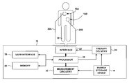
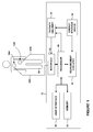
- FIG. 1 An exemplary embodiment of the medical device of the present invention is shown in FIG. 1 , and is designated generally by reference numeral 18 .
- defibrillator 12 is shown coupled to a patient 16 by electrodes 18 A and 18 B (collectively “electrodes 18 ”). Electrodes 18 may include hand-held electrode paddles or adhesive electrode pads placed on the skin of patient 16 . Electrodes 18 are coupled to defibrillator 12 via respective conductors 20 A and 20 B (collectively “conductors 20 ”) and an interface 22 . In a typical application, interface 22 includes a receptacle, and conductors 20 plug into the receptacle.
- Interface 22 includes a switch (not shown in FIG. 1 ) that, when activated, couples therapy delivery circuitry 24 to electrodes 18 for delivery of energy to patient 16 via electrodes 18 in the form of a defibrillation shock.
- the switch may be of conventional design and may be formed, for example, of electrically operated relays. Alternatively, the switch may comprise an arrangement of solid-state devices such as silicon-controlled rectifiers or insulated gate bipolar transistors.
- Therapy delivery circuitry 24 includes components, such as one or more capacitors, that store the energy to be delivered to patient 16 as a defibrillation shock. Before a defibrillation shock may be delivered to patient 16 , these energy storage components are charged by charging circuitry, such as a flyback charger, that transfers energy from energy storage device 14 such as a battery to the components. A processor 26 directs the charging circuitry to charge the energy storage components to a selected voltage level that is determined based on a selected energy level for the defibrillation shock to be delivered to patient 16 .
- charging circuitry such as a flyback charger
- Defibrillator 12 may be a manual defibrillator or an AED. Where defibrillator 12 is a manual defibrillator, a caregiver using defibrillator 12 may select an energy level for each defibrillation shock delivered to patient 12 .
- Processor 26 may receive the selection made by the caregiver via a user interface 28 , which may include input devices, such as a keypad and various buttons or dials, and output devices, such as various indicator lights, a cathode ray tube (CRT), light emitting diode (LED), or liquid crystal display (LCD) screen, and a speaker.
- input devices such as a keypad and various buttons or dials
- output devices such as various indicator lights, a cathode ray tube (CRT), light emitting diode (LED), or liquid crystal display (LCD) screen, and a speaker.
- CTR cathode ray tube
- LED light emitting diode
- LCD liquid crystal display
- processor 26 may select an energy level based on protocol stored in a memory 30 and the number of defibrillation shocks already delivered to patient 16 .
- the protocol may define a preprogrammed progression of energy levels and numbers of shocks to be delivered at each energy level.
- processor 26 controls user interface 28 to provide an indication to the caregiver that defibrillator 12 is ready to deliver a defibrillation shock to patient 16 , such as an indicator light or a voice prompt.
- the defibrillation shock may be delivered manually or automatically.
- the user may direct processor 26 to deliver the defibrillation shock via user interface 28 by, for example pressing a button.
- the processor 26 will automatically cause delivery of the defibrillating shock without further user interaction. In either case, processor 26 activates the switches of interface 22 to electrically connect therapy delivery circuit 24 to electrodes 18 , and thereby deliver the defibrillation shock to patient 16 .
- Processor 26 may perform other functions as well, such as monitoring electrical activity of the heart of patient 16 sensed via electrodes 18 .
- Processor 26 may determine whether the heart of patient 16 is fibrillating based upon the sensed electrical activity in order to determine whether a defibrillation shock should be delivered to patient 16 . Where a defibrillation shock has already been delivered, processor 26 may evaluate the efficacy of the delivered defibrillation shock by determining if the heart is still fibrillating in order to determine whether an additional defibrillation shock is warranted. Processor 26 may automatically deliver defibrillation shocks based on these determinations, or may advise the caregiver of these determinations via user interface 28 .
- Processor 26 may display an electrocardiogram (ECG) that reflects the sensed electrical activity via user interface 28 . Further, processor 26 may control delivery of other types of therapy to patient 16 via electrodes 18 , such as cardioversion or pacing therapy. Where defibrillator 12 is more fully featured, e.g., a manual paramedic or hospital defibrillator, defibrillator 12 may also include additional sensors (not shown) coupled to processor 26 , such as sensors to measure blood oxygen saturation, temperature, blood pressure, and the amount of carbon dioxide in the air inhaled or exhaled by patient 16 .
- ECG electrocardiogram
- Processor 26 may, for example, include one or more of a microprocessor, digital signal processor (DSP), application specific integrated circuit (ASIC), field programmable gate array (FPGA), or other logic circuitry.
- DSP digital signal processor
- ASIC application specific integrated circuit
- FPGA field programmable gate array
- memory 30 may include program instructions that cause processor 26 to perform the functions attributed to processor 26 herein.
- Memory 30 may include any of a variety of solid state, magnetic or optical media, such as random access memory (RAM), read-only memory (ROM), CD-ROM, magnetic disk, electrically erasable programmable ROM (EEPROM), or flash memory.
- processor 26 will perform a charge advisory analysis that will determine whether to commence charging the one or more capacitors in the therapy delivery circuitry prior to the determination by the shock advisory algorithm of whether delivery of a shock is advised. In some embodiments, this charge advisory analysis may also determine the rate at which the charging is performed.
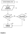
- a process for the charge advisory analysis is illustrated in the flowchart of FIG. 2 . In the illustrated embodiment, after the defibrillator is turned on in a first step 32 , the defibrillator provides data on sensed parameters to processor 26 in a second step 34 .
- These parameters may include the patient's physiological parameters such as ECG, or device parameters indicative of some condition of the defibrillator 12 such as electrode impedance or user interaction with the defibrillator 12 , or a combination of patient parameters and device parameters. If the sensed parameters meet criteria that would indicate some probability that a charge will be needed, then the processor would, in step 38 , direct the energy storage device 14 to commence charging the therapy delivery circuitry 24 . If the sensed parameters do not meet the charging criteria, then charging would not commence at that point in time. If, however, in step 40 , the clinical analysis results in shock being advised, then charging would be commenced at completion of the clinical determination that shock is advised.
- the charge advisory analysis may use relatively simple criteria for the charge decision.
- the processor 26 will analyze a short segment of ECG and begin charging if all of the following criteria are met: 1) no QRS complexes are detected, 2) a flat line is not detected, and 3) the electrodes are attached to a patient. This analysis can be done in a small fraction of the time needed for the clinical analysis to be completed. Other criteria that would indicate a desired probability that a charge will be needed may, of course, be used in alternative embodiments of the invention. The desired degree of probability may be low.
- the parameter detected in step 34 would be electrode impedance, and the criteria for charging in step 36 would be whether the electrode impendence is within a range that would indicated the electrodes are attached to the patient 16 .
- the defibrillator after the defibrillator is turned on, it measures the electrode impedance to see if the electrodes are attached to a patient. Electrode impedance within a specified range, typically between 10 to 300 ohms, would be generally reliable indication that the electrodes 18 have been applied to the patient 16 . Impedance outside this range would indicate that the electrodes 18 are not connected to a patient. Connection of electrodes to a patient would indicate a non-zero probability that a shock will be needed.
- the defibrillator would not begin charging.
- the charge advisory analysis could be repeated until either the electrodes are attached to a patient or the defibrillator is turned off.
- FIGS. 3 and 4 schematically illustrate the timing involved in two different scenarios in which embodiments of the invention are used.
- the horizontal arrow represents progression in time.
- the defibrillator is activated at T 0 .
- the charge advisory analysis is performed from T 0 to T 1 .
- the charge advisory analysis results in a determination that charging should be commenced, and charging is commenced approximately at time T 1 .
- the clinical shock advisory analysis is performed from T 0 to T 2 .
- the shock advisory analysis determines a shock is advised, and so charging is continued until it is completed at T 3 .
- the defibrillator is activated at T 0 ′.
- the charge advisory analysis is performed from T 0 ′ to T 1 ′.
- a charge advisory analysis does not result in a determination that charging should be commenced, and charging is not commenced at time T 1 ′. This would be the case the case where the sensed parameters input into the charging decision do not meet the chosen criteria.
- the clinical shock advisory analysis is performed from T 0 ′ to T 2 ′.
- the shock advisory analysis determines a shock is advised, and so charging commences at approximately T 2 ′ and continues until it is completed at T 3 ′.
- charging criteria are chosen so that, in most cases a determination to commence charging will be made prior to the shock advisory algorithm's determination that shock is advisable, then there will be a significant time saving in preparation for shock delivery in most cases where shock is advised.
- a charge advisory analysis process is capable of providing a determination of whether charging should be commenced based on sensed parameters indicative of the probability of whether a shock will be advised, with an increasing confidence level over time.
- this could be done by analyzing a first segment of a patient ECG and rendering a preliminary decision based on that analysis. A second segment of the ECG subsequent to the first segment could then be analyzed. If the two analyses agree, then one would have an increased confidence that the initial determination was correct. Similarly, additional segments could be analyzed on a continuous basis, providing increased confidence over time.
- the progressive output of the charge advisory analysis in this embodiment could be used to provide intelligent control of the defibrillator capacitor charger.
- the capacitor charger could be turned on at a first charge rate when the first Charge Advised determination is made. If a second Charge Advised determination agrees, then the charge rate could be increased. Finally, if the Shock Advisory Algorithm provides a shock advised decision before the capacitor is fully charged, then the charge rate would be increased to its maximum level.
- Another example of how charging could be controlled would be to charge the capacitor to a first charge level if an initial Charge Advised determination is made, and then charge to a second level if a second Charge Advised determination is made. This process of making progressive charge advisability determinations and charging to progressively higher levels may be repeated. If the Shock Advisory Algorithm advises that shock delivery is advised, charge would be completed, if it had not already been completed.
- This progressive control of the capacitor charger provides a couple of benefits.
- One benefit is a reduced risk of capacitor charger noise artifact appearing on the ECG signal, which is one of the possible drawbacks of charging while an ECG analysis is performed.
- the other benefit is the reduced likelihood that the energy will be wasted.
- This invention proposes a method of reducing the shock time delay while at the same time reducing the risk of wasted energy through unnecessary charging, reducing the hazard of having energy available when it is not required and minimizing the effect of charging artifact on the signal analysis.
- This invention proposes a method and device in which clinical analysis algorithms may operate, providing timely assessment of the patient status, and correctly preparing the device to support a patient in the most rapid fashion possible.
- the charging criterion is chosen to result in a Charging Advised determination in cases where a desired likelihood or probability that a shock will be advised is met.
- the parameters upon which this determination is made may include any of a signal such as ECG, or any of subset of similar signals giving a measure of cardiac activity, including, for example, ECG from multiple sites, transthoracic impedance, electric field plethysmography, photoplethysmography, cardiokymographic, ballistocardiographic, or acoustic plethysmography.
- Data on the state of the defibrillator or how a user is interacting with a defibrillator may be used to make a determination of whether the desired level of probability has been met. These may include, for example, whether the user has applied the electrodes to the patient, or other operator actions such as connecting the electrodes to the defibrillator, opening the electrode pouch, removing the electrodes from the pouch, removing the backing material from the electrodes, or performing CPR on the patient
Abstract
Description
Claims (25)
Priority Applications (1)
| Application Number | Priority Date | Filing Date | Title |
|---|---|---|---|
| US13/032,400 US8831719B2 (en) | 2004-12-09 | 2011-02-22 | External defibrillator with charge advisory algorithm |
Applications Claiming Priority (2)
| Application Number | Priority Date | Filing Date | Title |
|---|---|---|---|
| US11/008,876 US7904152B2 (en) | 2004-12-09 | 2004-12-09 | External defibrillator with charge advisory algorithm |
| US13/032,400 US8831719B2 (en) | 2004-12-09 | 2011-02-22 | External defibrillator with charge advisory algorithm |
Related Parent Applications (1)
| Application Number | Title | Priority Date | Filing Date |
|---|---|---|---|
| US11/008,876 Division US7904152B2 (en) | 2004-12-09 | 2004-12-09 | External defibrillator with charge advisory algorithm |
Publications (2)
| Publication Number | Publication Date |
|---|---|
| US20110144707A1 US20110144707A1 (en) | 2011-06-16 |
| US8831719B2 true US8831719B2 (en) | 2014-09-09 |
Family
ID=36585060
Family Applications (2)
| Application Number | Title | Priority Date | Filing Date |
|---|---|---|---|
| US11/008,876 Active 2027-12-21 US7904152B2 (en) | 2004-12-09 | 2004-12-09 | External defibrillator with charge advisory algorithm |
| US13/032,400 Active 2025-03-18 US8831719B2 (en) | 2004-12-09 | 2011-02-22 | External defibrillator with charge advisory algorithm |
Family Applications Before (1)
| Application Number | Title | Priority Date | Filing Date |
|---|---|---|---|
| US11/008,876 Active 2027-12-21 US7904152B2 (en) | 2004-12-09 | 2004-12-09 | External defibrillator with charge advisory algorithm |
Country Status (1)
| Country | Link |
|---|---|
| US (2) | US7904152B2 (en) |
Families Citing this family (20)
| Publication number | Priority date | Publication date | Assignee | Title |
|---|---|---|---|---|
| EP1251908B1 (en) * | 2000-02-04 | 2017-04-05 | Zoll Medical Corporation | Integrated resuscitation |
| US7920917B2 (en) * | 2003-07-17 | 2011-04-05 | Physio-Control, Inc. | External defibrillator and methods for operating the external defibrillator |
| US6961612B2 (en) * | 2003-02-19 | 2005-11-01 | Zoll Medical Corporation | CPR sensitive ECG analysis in an automatic external defibrillator |
| US20050101889A1 (en) | 2003-11-06 | 2005-05-12 | Freeman Gary A. | Using chest velocity to process physiological signals to remove chest compression artifacts |
| WO2005112749A1 (en) | 2004-05-12 | 2005-12-01 | Zoll Medical Corporation | Ecg rhythm advisory method |
| US7565194B2 (en) * | 2004-05-12 | 2009-07-21 | Zoll Medical Corporation | ECG rhythm advisory method |
| US7904152B2 (en) * | 2004-12-09 | 2011-03-08 | Physio-Control, Inc. | External defibrillator with charge advisory algorithm |
| EP2172245B1 (en) | 2008-10-03 | 2017-04-12 | Schiller Medical S.A.S. | Apparatus for defibrillation delivery decision |
| US8594784B2 (en) | 2009-02-20 | 2013-11-26 | Babric Life Science Innovations, Llc. | Kits and methods for retrofitting and adapting common notebooks, laptop computers, and tablets, to enable each to be used as an automated external defibrillator (AED), and as a manual defibrillator |
| US9168386B2 (en) * | 2009-02-20 | 2015-10-27 | Comptolife, Llc | Adaptation of the common notebook, laptop computer, netbook and tablet PC computer to enable each to be used as an automated external defibrillator (AED) to treat victims of sudden cardiac arrest |
| US8265737B2 (en) * | 2009-10-27 | 2012-09-11 | Cameron Health, Inc. | Methods and devices for identifying overdetection of cardiac signals |
| US9126055B2 (en) | 2012-04-20 | 2015-09-08 | Cardiac Science Corporation | AED faster time to shock method and device |
| JP2016531663A (en) | 2013-08-01 | 2016-10-13 | ゾール メディカル コーポレイションZOLL Medical Corporation | System and method for utilizing an identification device in a wearable medical treatment device |
| EP3362143B1 (en) | 2015-10-16 | 2023-09-27 | Zoll Medical Corporation | Dual sensor electrodes for providing enhanced resuscitation feedback |
| US10118047B2 (en) * | 2016-01-03 | 2018-11-06 | Igor Abramov | Automatic defibrillation system |
| US11607555B2 (en) | 2016-12-12 | 2023-03-21 | Avive Solutions, Inc. | Defibrillator discharge control |
| US10449380B2 (en) | 2016-12-12 | 2019-10-22 | Revive Solutions, Inc. | Defibrillator |
| US10903675B2 (en) | 2016-12-12 | 2021-01-26 | Avive Solutions, Inc. | Medical device draw current regulation |
| JP7257681B2 (en) | 2016-12-12 | 2023-04-14 | アバイブ・ソリューションズ・インコーポレーテッド | defibrillator |
| KR101957154B1 (en) | 2018-04-02 | 2019-07-04 | 주식회사메디아나 | Defibrillator drive method capable of early defibrillation and its defibrillator |
Citations (25)
| Publication number | Priority date | Publication date | Assignee | Title |
|---|---|---|---|---|
| US4179945A (en) | 1978-09-05 | 1979-12-25 | The Singer Company | Variable step size impulse drive |
| US5097830A (en) | 1990-03-30 | 1992-03-24 | Laerdal Manufacturing Corporation | Defibrillator with reliability verification |
| US5111813A (en) | 1990-05-18 | 1992-05-12 | Hewlett-Packard Company | Defibrillation employing an impedance-corrected delivered energy |
| US5191884A (en) | 1987-09-02 | 1993-03-09 | Telectronics N.V. | Reconfirmation prior to shock for implantable defibrillation |
| US5391187A (en) | 1994-02-22 | 1995-02-21 | Zmd Corporation | Semiautomatic defibrillator with heart rate alarm driven by shock advisory algorithm |
| US5423863A (en) | 1990-12-13 | 1995-06-13 | Odam, S.A. | Method of recognizing a ventricular cardiac pathological condition for automatic defibrillation purposes, and monitor-defibrillator for implementing said method |
| US5496349A (en) | 1994-03-11 | 1996-03-05 | Physio-Control Corporation | Method and system for automatic or semi-automatic defilbrillation using redundant processing |
| US5607454A (en) | 1993-08-06 | 1997-03-04 | Heartstream, Inc. | Electrotherapy method and apparatus |
| US5700281A (en) | 1996-06-04 | 1997-12-23 | Survivalink Corporation | Stage and state monitoring automated external defibrillator |
| US5797969A (en) | 1995-08-01 | 1998-08-25 | Survivalink Corporation | One button lid activated automatic external defibrillator |
| US6005370A (en) | 1998-01-26 | 1999-12-21 | Physio-Control Manufacturing Corporation | Automatic rate control for defibrillator capacitor charging |
| US6029085A (en) | 1997-04-09 | 2000-02-22 | Survivalink Corporation | Charging and safety control for automated external defibrillator and method |
| US6029084A (en) | 1995-04-13 | 2000-02-22 | Alistair Ross MacNicol | Therapeutic field generator |
| US6241751B1 (en) | 1999-04-22 | 2001-06-05 | Agilent Technologies, Inc. | Defibrillator with impedance-compensated energy delivery |
| US6289243B1 (en) | 1999-12-01 | 2001-09-11 | Cardiac Science, Inc. | Automatic external cardioverter/defibrillator with tachyarrhythmia detector using a modulation (amplitude and frequency) domain function |
| US6304773B1 (en) | 1998-05-21 | 2001-10-16 | Medtronic Physio-Control Manufacturing Corp. | Automatic detection and reporting of cardiac asystole |
| US6553251B1 (en) | 1999-11-05 | 2003-04-22 | Polar Electro Oy | Method and arrangement for heartbeat detection |
| US6553257B2 (en) | 2001-03-13 | 2003-04-22 | Koninklijke Philips Electronics N.V. | Interactive method of performing cardipulmonary resuscitation with minimal delay to defibrillation shocks |
| US6658290B1 (en) * | 2000-06-12 | 2003-12-02 | Cardiac Science, Inc. | Public access defibrillator |
| US20040064157A1 (en) * | 2002-09-30 | 2004-04-01 | Norton John D. | Method and apparatus for maintaining energy storage in an electrical storage device |
| US20040172068A1 (en) * | 2003-01-31 | 2004-09-02 | Sullivan Joseph L. | Apparatus and methods for fibrillation and defibrillation |
| US20040249418A1 (en) * | 2001-09-21 | 2004-12-09 | Mills Desmond Bryan | Defibrillator |
| US7027863B1 (en) * | 1999-10-25 | 2006-04-11 | Impulse Dynamics N.V. | Device for cardiac therapy |
| US20060129190A1 (en) | 2004-12-09 | 2006-06-15 | Sullivan Joseph L | External defibrillator with charge advisory algorithm |
| US7242979B1 (en) | 2002-09-20 | 2007-07-10 | Medtronic Physio-Control Manufacturing Corporation | External defibrillator and methods for operating the external defibrillator |
Family Cites Families (3)
| Publication number | Priority date | Publication date | Assignee | Title |
|---|---|---|---|---|
| US5179945A (en) * | 1991-01-17 | 1993-01-19 | Cardiac Pacemakers, Inc. | Defibrillation/cardioversion system with multiple evaluation of heart condition prior to shock delivery |
| US5817132A (en) * | 1997-05-09 | 1998-10-06 | Cedars-Sinai Medical Center | Defibrillation apparatus and method |
| US6754526B2 (en) * | 2000-11-13 | 2004-06-22 | Medtronic Physio-Control Corp | Defibrillator with a multiple-mode interface |
-
2004
- 2004-12-09 US US11/008,876 patent/US7904152B2/en active Active
-
2011
- 2011-02-22 US US13/032,400 patent/US8831719B2/en active Active
Patent Citations (25)
| Publication number | Priority date | Publication date | Assignee | Title |
|---|---|---|---|---|
| US4179945A (en) | 1978-09-05 | 1979-12-25 | The Singer Company | Variable step size impulse drive |
| US5191884A (en) | 1987-09-02 | 1993-03-09 | Telectronics N.V. | Reconfirmation prior to shock for implantable defibrillation |
| US5097830A (en) | 1990-03-30 | 1992-03-24 | Laerdal Manufacturing Corporation | Defibrillator with reliability verification |
| US5111813A (en) | 1990-05-18 | 1992-05-12 | Hewlett-Packard Company | Defibrillation employing an impedance-corrected delivered energy |
| US5423863A (en) | 1990-12-13 | 1995-06-13 | Odam, S.A. | Method of recognizing a ventricular cardiac pathological condition for automatic defibrillation purposes, and monitor-defibrillator for implementing said method |
| US5607454A (en) | 1993-08-06 | 1997-03-04 | Heartstream, Inc. | Electrotherapy method and apparatus |
| US5391187A (en) | 1994-02-22 | 1995-02-21 | Zmd Corporation | Semiautomatic defibrillator with heart rate alarm driven by shock advisory algorithm |
| US5496349A (en) | 1994-03-11 | 1996-03-05 | Physio-Control Corporation | Method and system for automatic or semi-automatic defilbrillation using redundant processing |
| US6029084A (en) | 1995-04-13 | 2000-02-22 | Alistair Ross MacNicol | Therapeutic field generator |
| US5797969A (en) | 1995-08-01 | 1998-08-25 | Survivalink Corporation | One button lid activated automatic external defibrillator |
| US5700281A (en) | 1996-06-04 | 1997-12-23 | Survivalink Corporation | Stage and state monitoring automated external defibrillator |
| US6029085A (en) | 1997-04-09 | 2000-02-22 | Survivalink Corporation | Charging and safety control for automated external defibrillator and method |
| US6005370A (en) | 1998-01-26 | 1999-12-21 | Physio-Control Manufacturing Corporation | Automatic rate control for defibrillator capacitor charging |
| US6304773B1 (en) | 1998-05-21 | 2001-10-16 | Medtronic Physio-Control Manufacturing Corp. | Automatic detection and reporting of cardiac asystole |
| US6241751B1 (en) | 1999-04-22 | 2001-06-05 | Agilent Technologies, Inc. | Defibrillator with impedance-compensated energy delivery |
| US7027863B1 (en) * | 1999-10-25 | 2006-04-11 | Impulse Dynamics N.V. | Device for cardiac therapy |
| US6553251B1 (en) | 1999-11-05 | 2003-04-22 | Polar Electro Oy | Method and arrangement for heartbeat detection |
| US6289243B1 (en) | 1999-12-01 | 2001-09-11 | Cardiac Science, Inc. | Automatic external cardioverter/defibrillator with tachyarrhythmia detector using a modulation (amplitude and frequency) domain function |
| US6658290B1 (en) * | 2000-06-12 | 2003-12-02 | Cardiac Science, Inc. | Public access defibrillator |
| US6553257B2 (en) | 2001-03-13 | 2003-04-22 | Koninklijke Philips Electronics N.V. | Interactive method of performing cardipulmonary resuscitation with minimal delay to defibrillation shocks |
| US20040249418A1 (en) * | 2001-09-21 | 2004-12-09 | Mills Desmond Bryan | Defibrillator |
| US7242979B1 (en) | 2002-09-20 | 2007-07-10 | Medtronic Physio-Control Manufacturing Corporation | External defibrillator and methods for operating the external defibrillator |
| US20040064157A1 (en) * | 2002-09-30 | 2004-04-01 | Norton John D. | Method and apparatus for maintaining energy storage in an electrical storage device |
| US20040172068A1 (en) * | 2003-01-31 | 2004-09-02 | Sullivan Joseph L. | Apparatus and methods for fibrillation and defibrillation |
| US20060129190A1 (en) | 2004-12-09 | 2006-06-15 | Sullivan Joseph L | External defibrillator with charge advisory algorithm |
Non-Patent Citations (2)
| Title |
|---|
| Tchoudovski et al., "New Approach in Developing of the Algorithms for Resuscitation Assistance," Proceedings of the 26th Annual International Conference of the IEEE EMBS, San Fransisco, CA, Sep. 1-5, 2004. pp. 956-959. |
| Yi-Sheng, Zhu et al., "Detection of Ventricular Fibrillation by Sequential Testing," Biomedical Engineering Department, John Hopkins Medical School, Baltimore, MD IEEE 1989 pp. 325-328. |
Also Published As
| Publication number | Publication date |
|---|---|
| US7904152B2 (en) | 2011-03-08 |
| US20060129190A1 (en) | 2006-06-15 |
| US20110144707A1 (en) | 2011-06-16 |
Similar Documents
| Publication | Publication Date | Title |
|---|---|---|
| US8831719B2 (en) | External defibrillator with charge advisory algorithm | |
| US11389660B2 (en) | Defibrillator that monitors CPR treatment and adjusts protocol | |
| US10537746B2 (en) | Automatic external defibrillator with increased CPR administration time | |
| US7920917B2 (en) | External defibrillator and methods for operating the external defibrillator | |
| US6671547B2 (en) | Adaptive analysis method for an electrotherapy device and apparatus | |
| US6269267B1 (en) | Configurable arrhythmia analysis algorithm with security interface | |
| US6553257B2 (en) | Interactive method of performing cardipulmonary resuscitation with minimal delay to defibrillation shocks | |
| US20090270930A1 (en) | External Defibrillator With Adaptive Protocols | |
| US7937146B2 (en) | Defibrillator with overridable CPR-first protocol | |
| US10195451B2 (en) | Medical device with lack-of-readiness alarm | |
| US7242979B1 (en) | External defibrillator and methods for operating the external defibrillator | |
| US20100082075A1 (en) | Defibrillator with cpr-ventilation analysis utilizing patient physiological data | |
| US20040138713A1 (en) | External defibrillation and transcutaneous pacing device and methods for operating the device | |
| US10046170B2 (en) | Defibrillator with overridable CPR-first protocol |
Legal Events
| Date | Code | Title | Description |
|---|---|---|---|
| AS | Assignment |
Owner name: PHYSIO-CONTROL, INC., WASHINGTON Free format text: CHANGE OF NAME;ASSIGNOR:MEDTRONIC EMERGENCY RESPONSE SYSTEMS, INC.;REEL/FRAME:027008/0918 Effective date: 20061201 |
|
| AS | Assignment |
Owner name: BANK OF NEW YORK MELLON TRUST COMPANY, N.A., AS *C Free format text: SECURITY AGREEMENT;ASSIGNOR:PHYSIO-CONTROL, INC.;REEL/FRAME:027765/0861 Effective date: 20120130 |
|
| AS | Assignment |
Owner name: CITIBANK, N.A., AS COLLATERAL AGENT, NEW YORK Free format text: SECURITY AGREEMENT;ASSIGNOR:PHYSIO-CONTROL, INC.;REEL/FRAME:027763/0881 Effective date: 20120130 |
|
| AS | Assignment |
Owner name: MEDTRONIC EMERGENCY RESPONSE SYSTEMS, INC., WASHIN Free format text: ASSIGNMENT OF ASSIGNORS INTEREST;ASSIGNOR:NOVA, RICHARD C.;REEL/FRAME:027982/0310 Effective date: 20111209 Owner name: MEDTRONIC EMERGENCY RESPONSE SYSTEMS, INC., WASHIN Free format text: ASSIGNMENT OF ASSIGNORS INTEREST;ASSIGNORS:SULLIVAN, JOSEPH L.;KELLY, PATRICK F.;TAYLOR, JAMES W.;SIGNING DATES FROM 20050318 TO 20050721;REEL/FRAME:027982/0276 |
|
| STCF | Information on status: patent grant |
Free format text: PATENTED CASE |
|
| AS | Assignment |
Owner name: MEDTRONIC EMERGENCY RESPONSE SYSTEMS, INC., WASHIN Free format text: CORRECTIVE ASSIGNMENT TO CORRECT THE 12/9/2011 ASSIGNMENT FROM R. NOVA AND REPLACE IT WITH THE ORIGINAL 7/21/2005 ASSIGNMENT EXECUTED BY HIM. THE 2011 ASSIGNMENT WAS PREVIOUSLY RECORDED ON REEL 027982 FRAME 0310. ASSIGNOR(S) HEREBY CONFIRMS THE ORIGINAL 7/21/2005 ASSIGNMENT. THE 2011 ASSIGNMENT WAS EXECUTED IN ERROR;ASSIGNOR:NOVA, RICHARD C.;REEL/FRAME:036214/0693 Effective date: 20050721 |
|
| AS | Assignment |
Owner name: PHYSIO-CONTROL, INC., WASHINGTON Free format text: RELEASE BY SECURED PARTY;ASSIGNOR:THE BANK OF NEW YORK MELLON TRUST COMPANY, N.A.;REEL/FRAME:037519/0240 Effective date: 20150605 |
|
| AS | Assignment |
Owner name: CITIBANK, N.A., AS COLLATERAL AGENT, NEW YORK Free format text: FIRST LIEN SECURITY AGREEMENT;ASSIGNORS:PHYSIO-CONTROL, INC.;PHYSIO-CONTROL INTERNATIONAL, INC.;REEL/FRAME:037532/0828 Effective date: 20150605 |
|
| AS | Assignment |
Owner name: CITIBANK, N.A., AS COLLATERAL AGENT, NEW YORK Free format text: SECOND LIEN SECURITY AGREEMENT;ASSIGNORS:PHYSIO-CONTROL, INC.;PHYSIO-CONTROL INTERNATIONAL, INC.;REEL/FRAME:037559/0601 Effective date: 20150605 |
|
| AS | Assignment |
Owner name: PHYSIO-CONTROL, INC., WASHINGTON Free format text: RELEASE BY SECURED PARTY;ASSIGNOR:CITIBANK, N.A.;REEL/FRAME:038376/0806 Effective date: 20160405 Owner name: PHYSIO-CONTROL INTERNATIONAL, INC., WASHINGTON Free format text: RELEASE BY SECURED PARTY;ASSIGNOR:CITIBANK, N.A.;REEL/FRAME:038379/0001 Effective date: 20160405 Owner name: PHYSIO-CONTROL INTERNATIONAL, INC., WASHINGTON Free format text: RELEASE BY SECURED PARTY;ASSIGNOR:CITIBANK, N.A.;REEL/FRAME:038378/0028 Effective date: 20160405 Owner name: PHYSIO-CONTROL, INC., WASHINGTON Free format text: RELEASE BY SECURED PARTY;ASSIGNOR:CITIBANK, N.A.;REEL/FRAME:038379/0001 Effective date: 20160405 Owner name: PHYSIO-CONTROL, INC., WASHINGTON Free format text: RELEASE BY SECURED PARTY;ASSIGNOR:CITIBANK, N.A.;REEL/FRAME:038378/0028 Effective date: 20160405 |
|
| MAFP | Maintenance fee payment |
Free format text: PAYMENT OF MAINTENANCE FEE, 4TH YEAR, LARGE ENTITY (ORIGINAL EVENT CODE: M1551) Year of fee payment: 4 |
|
| MAFP | Maintenance fee payment |
Free format text: PAYMENT OF MAINTENANCE FEE, 8TH YEAR, LARGE ENTITY (ORIGINAL EVENT CODE: M1552); ENTITY STATUS OF PATENT OWNER: LARGE ENTITY Year of fee payment: 8 |