US8831748B2 - Medical electrical electrodes with conductive polymer - Google Patents
Medical electrical electrodes with conductive polymer Download PDFInfo
- Publication number
- US8831748B2 US8831748B2 US12/414,265 US41426509A US8831748B2 US 8831748 B2 US8831748 B2 US 8831748B2 US 41426509 A US41426509 A US 41426509A US 8831748 B2 US8831748 B2 US 8831748B2
- Authority
- US
- United States
- Prior art keywords
- tubing
- coil
- conductive coil
- elongated conductive
- polymer material
- Prior art date
- Legal status (The legal status is an assumption and is not a legal conclusion. Google has not performed a legal analysis and makes no representation as to the accuracy of the status listed.)
- Active, expires
Links
Images


Classifications
-
- A—HUMAN NECESSITIES
- A61—MEDICAL OR VETERINARY SCIENCE; HYGIENE
- A61N—ELECTROTHERAPY; MAGNETOTHERAPY; RADIATION THERAPY; ULTRASOUND THERAPY
- A61N1/00—Electrotherapy; Circuits therefor
- A61N1/02—Details
- A61N1/04—Electrodes
- A61N1/05—Electrodes for implantation or insertion into the body, e.g. heart electrode
- A61N1/056—Transvascular endocardial electrode systems
- A61N1/0563—Transvascular endocardial electrode systems specially adapted for defibrillation or cardioversion
-
- Y—GENERAL TAGGING OF NEW TECHNOLOGICAL DEVELOPMENTS; GENERAL TAGGING OF CROSS-SECTIONAL TECHNOLOGIES SPANNING OVER SEVERAL SECTIONS OF THE IPC; TECHNICAL SUBJECTS COVERED BY FORMER USPC CROSS-REFERENCE ART COLLECTIONS [XRACs] AND DIGESTS
- Y10—TECHNICAL SUBJECTS COVERED BY FORMER USPC
- Y10T—TECHNICAL SUBJECTS COVERED BY FORMER US CLASSIFICATION
- Y10T29/00—Metal working
- Y10T29/49—Method of mechanical manufacture
- Y10T29/49002—Electrical device making
- Y10T29/49117—Conductor or circuit manufacturing
Landscapes
- Health & Medical Sciences (AREA)
- Heart & Thoracic Surgery (AREA)
- Cardiology (AREA)
- Nuclear Medicine, Radiotherapy & Molecular Imaging (AREA)
- Engineering & Computer Science (AREA)
- Biomedical Technology (AREA)
- Vascular Medicine (AREA)
- Radiology & Medical Imaging (AREA)
- Life Sciences & Earth Sciences (AREA)
- Animal Behavior & Ethology (AREA)
- General Health & Medical Sciences (AREA)
- Public Health (AREA)
- Veterinary Medicine (AREA)
- Electrotherapy Devices (AREA)
- Treatments Of Macromolecular Shaped Articles (AREA)
Abstract
A medical electrical electrode includes an elongated conductive coil located over a lead body, and a conductive polymer material in contact with the lead body and located between individual coils of the elongated conductive coil. In certain embodiments, the conductive polymer is a polymer (e.g., silicone) implanted with a conductive filler (e.g., carbon black). In certain embodiments, the conductive polymer material is generally isodiametric with an outer diameter of the individual coils of the elongated conductive coil. A medical electrical electrode is fabricated by sliding an elongated conductive coil over a length of a lead body, dispersing a conductive polymer on the helical coil, inserting a tubing over the elongated conductive coil, distributing the polymer material between individual turns of the elongated conductive coil, heating the tubing so the tubing shrinks around the elongated conductive coil, and removing the tubing.
Description
This application is a continuation of U.S. patent application Ser. No. 11/113,867 filed on Apr. 25, 2005, now U.S. Pat. No. 7,512,447. The disclosure(s) of the above application(s) is (are) incorporated herein by reference.
The present invention relates to medical electrical stimulation electrodes generally, and more specifically, to defibrillation electrodes.
Implantable medical devices are used to provide therapy to patients suffering from a variety of conditions. Examples of implantable medical devices are pacemakers and cardioverter-defibrillators (ICDs), which are electronic medical devices that monitor the electrical activity of the heart and provide electrical stimulation to one or more of the heart chambers, when necessary. For example, pacemakers are designed to sense arrhythmias, i.e., disturbances in heart rhythm, and in turn, provide appropriate electrical stimulation pulses, at a controlled rate, to selected chambers of the heart in order to correct the arrhythmias and restore the proper heart rhythm. The types of arrhythmias that may be detected and corrected by pacemakers include bradycardias, which are unusually slow heart rates, and certain tachycardias, which are unusually fast heart rates.
Cardioverter-defibrillators (ICDs) also detect arrhythmias and provide appropriate electrical stimulation pulses to selected chambers of the heart to correct the abnormal heart rate. In contrast to pacemakers, however, an ICD can also provide pulses that are much stronger and less frequent. This is because ICDs are generally designed to correct fibrillation, which is a rapid, unsynchronized quivering of one or more heart chambers, and severe tachycardias, where the heartbeats are very fast but coordinated. To correct such arrhythmias, ICDs deliver low, moderate, or high-energy shocks to the heart.
The electrical energy for the shocks generated by ICDs is delivered to the heart via electrical stimulation electrodes. One or more capacitors within the ICD are capable of rapidly delivering that energy to the patient's heart through leads that electrically connect the capacitors to the electrodes. In order to provide timely therapy to the patient after the detection of ventricular fibrillation, for example, it is necessary to charge the capacitors with the required amount of energy as quickly as possible. Thus, a battery in an ICD generally has a high rate capability to provide the necessary current to charge the capacitors.
In some designs, ICDs use large surface area electrodes either to be placed endocardially, epicardially or subcutaneously. One well-known approach of providing a large surface area electrode is to employ an elongated exposed coil of biocompatible metal. As is known, such elongated coils can be used with a wide variety of leads. For example, with an epicardial lead, an elongated coil serving as the electrode can be mounted around the exterior of an insulative lead body. In this context, it has been desirable to stabilize the electrode coil with respect to the lead body, both to provide mechanical integrity and to prevent fibrous growth around the individual coils of the electrode coil. In some designs, this has been accomplished by sliding the electrode coil over the lead body and backfilling spaces between the coil and the lead body with a plastic material. The exterior surface of the electrode coil is then machined to provide a smooth surface. Alternatively, the backfilling material may be removed by means of well-known plasma etching methods. Generally, the process can be varied as desired in order to provide the warranted amount of exposed surface area for the coil wire. For example, the removal process may be provided so that the backfilling material only extends radially outward between the turns of the coil from about one-third to one-half the diameter of the coil wire.
Alternative methods of making similar defibrillation lead structures without the necessity of using a backfilling can employ materials such as polyurethane to stabilize the electrode coil and to fill between the turns of the coil. In certain methods, a plastic tube can be stretched so that it displays an inner and outer diameter less than the inner and outer diameter of the tube in a relaxed state. An electrode coil having a inner diameter less than the outer diameter of the tube in its relaxed state is then slide over the stretched tube, after which the tube is released, allowing it to return to its previous length. However, after such release, the tube remains in a partially compressed state because of its contact with the electrode coil throughout the coil's length. Thereafter, a mandrel having an outer diameter greater than the inner diameter of the tubing in its compressed state is passed into the tubing, to further compress the tubing between the mandrel and the conductor coil. The assembly is thereafter heated, allowing the tubing to flow into spaces between the electrode coil.
While the methods of providing a plastic or polyurethane material between the electrode coil and lead body described above have been generally used, each has shortcomings. One particular shortcoming, with respect to both methods, is that there is variability in the pressure applied to the plastic or polyurethane material when situated between the individual coils of the electrode coil. As such, an uneven structure is often produced in which the plastic or polyurethane material does not flow outward to a consistent dimension between the individual coils. The present invention is directed to overcoming, or at least reducing the effects of, this shortcoming as well as others.
Generally, coil type electrodes of defibrillators are not uniform in terms of their geometry and electric field, which may cause cell in-growth and uneven electric discharge. The ideal materials to coat such coil electrodes are those that (1) are reasonably electric conductive, (2) are flexible and strong and have good adhesion to other parts so that the electrodes can be made flexible and durable, (3) have solid structure so cell in-growth is prevented, and (4) are biostable and compatible for implant in humans. In certain embodiments, such material is a polymer filled with a conductive filler. Silicone is generally considered a qualified polymer for implant applications. Carbon black can be made to have good conductivity, good polymeric (flexible and strong) mechanical properties, and good adhesion properties to metal. As such, carbon black can be used as the conductive filler. Carbon black is also quite inert. Therefore, a carbon black filled silicone has been found to be compatible as well as biostable in this application. Also, carbon black filled silicone is solid, which makes it different from other porous conductive materials e.g. ETFE (Ethylene-Tetrafluoroethylene) porous tubing. As such, cell in-growth can be prevented.
The conductive polymer is used to backfill the defibrillation coils of a high voltage lead and because of its conductive nature, allows complete coverage of the area between the coils of the defibrillation electrode without affecting the electrical performance of the lead. The increase in backfill creates a smoother outer surface that can help prevent tissue ingrowth and may improve lead extraction. The process of applying the conductive backfill to the defibrillation electrode is automated and shrink tubing is used to form the polymer.
The following discussion is presented to enable a person skilled in the art to make and use the present teachings. Various modifications to the illustrated embodiments will be readily apparent to those skilled in the art, and the generic principles herein may be applied to other embodiments and applications without departing from the present teachings. Thus, the present teachings are not intended to be limited to embodiments shown, but are to be accorded the widest scope consistent with the principles and features disclosed herein. The following detailed description is to be read with reference to the figures, in which like elements in different figures have like reference numerals. The figures, which are not necessarily to scale, depict selected embodiments and are not intended to limit the scope of the present teachings. Skilled artisans will recognize the examples provided herein have many useful alternatives and fall within the scope of the present teachings.
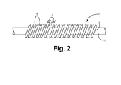
The gaps 4 defined by the spring wire 2 are filled with a pliable material 6 which maintains its integrity notwithstanding flexions of the lead body 10 and its conductive coil discharge surface. Such material is often an electrically insulating elastomeric, medical-grade adhesive, e.g., Nusil MED-1137A, so that only the outer peripheral surface of the helical coil spring wire 2 is electrically exposed to the body. However, in embodiments of the invention, the filler material 6 is made to be conductive, thereby providing an increased longitudinal contact body for the defibrillation electrode 12. The filler material 6 extends radially outward from the lead body 10 between the individual coils of the electrode 12.
With reference to FIG. 1 , the proximal end of the lead 8 generally carries a connector assembly. In certain embodiments, as shown, the connector assembly begins with a molded lead bifurcation 20, which splits off two of the conductors within lead body 10 to a bipolar, in-line connector assembly 24, generally corresponding to the IS-1 connector standard for pacing leads. However, other types of connector assemblies may also be adapted to practice the present invention. Connector assembly 24 is provided with a first set of sealing rings 28, a connector ring 32, a second sealing ring 34 and connector pin 36. Connector pin 36 is coupled to the conductor which extends through the lead body 10 to the tip electrode 16. The connector ring 32 is coupled to the conductor which extends through the lead body 10 to the ring electrode 14. The conductor coupled to defibrillation electrode 12 extends into connector assembly 22, which carries a set of sealing rings 26 and a connector pin 30, coupled to the conductor extending through lead body 10 to defibrillation electrode 12.
Extending distally from the defibrillation electrode 12, the lead 8 takes the form of a molded piece part carrying the ring electrode 14, which is in turn coupled to stranded conductor 112 (not visible in this view). Electrode 16, as exemplarily illustrated, is a steroid-eluting electrode, provided with a monolithic controlled release device 30 located within a chamber within the electrode. Electrode 16 is coupled to a coiled conductor 116 and 118 by means of an external crimping sleeve 32, which compresses conductor 118 against conductor 116 and compresses conductor 116 against the proximal portion of the electrode 16. Other types of tip electrodes, including screw-in electrodes may of course be substituted for electrode 16. Similarly, other mechanisms may be employed to interconnect conductors 118 and 116 and electrode 16, including welding, swaging, crimping and combinations thereof, including mechanisms disclosed in commonly assigned U.S. Pat. No. 5,676,694 to Boser et al. granted Oct. 14, 1997, and U.S. Pat. No. 6,026,567 granted Feb. 22, 2000, incorporated herein by reference in their entirety.
The conductor 114 passes through an internal lumen 100 within lead body 10, and has its insulation removed in areas in which it passes cross-bore crimp sleeves 36 and 38. The sleeves 36, 38 are preferably fabricated of an inert, conductive metal such as platinum to which the defibrillation electrode 12 can be readily welded. Proximal and distal ends of the defibrillation electrode 12 can be seen respectively at 12A and 12B as occupying the cross bores in the sleeves 36, 38. The sleeves 36, 38 are crimped to the conductor 114 and portions of the proximal end 12A and distal end 12B of the defibrillation electrode 12 are respectively inserted through the cross bores and such entry and exit points of the electrode 12 are respectively laser welded to the corresponding sleeves 36, 38. As previously mentioned with reference to FIG. 1 , the conductor 114 serves to couple the defibrillation electrode 12 to an ICD via the connector assembly 22. It should be appreciated that the conductor assembly 22 (including the conductor 114) may be manufactured using any conventional technique known to the art and coupled to the sleeves 36 and/or 38 using any conventional technique known to the art such as crimping, welding, etc.
In certain embodiments, surrounding the proximal portion of defibrillation electrode 12 is an outer insulative sheath 42 which extends proximally to the end of the lead 8. The sheath 42 covers the proximal end 12A of the defibrillation electrode 12. At the distal end of the lead 8, an outer insulative sheath 40 covers the distal end 12B of the defibrillation electrode 12 and may extend distally to one or more pacing electrodes coupled to conductors within the body of the lead 8, as shown. In certain embodiments, the outer insulative sheaths 40, 42 are fabricated of an polyurethane of one of the types typically used in conjunction with cardiac pacing leads and are preferably mechanically coupled to the proximal and distal ends of the defibrillation electrode 12 by means of an adhesive to further stabilize their locations.
It should be appreciated that other lead configurations are just as applicable to the embodiments of the invention, provided that at least one of the electrodes on the lead is a defibrillation electrode (as described herein) or is a further electrode configuration that can be backfilled with a polymeric material. With other lead embodiments, if fewer electrodes are provided on the lead body, correspondingly fewer conductors shall be included in the lead design. However, the incorporation of any defibrillation electrode or other electrode configuration as described above on any lead body can be applicable as described herein.
As mentioned previously, with respect to FIG. 2 , the remaining space defined between the individual coils of the defibrillation electrode 12 includes the polymeric material 6. The material 6 is conductive, thereby providing an increased longitudinal contact body for the defibrillation electrode 12. As such, the polymeric material 6 will slightly decrease shocking impedance when compared to equivalent electrodes backfilled with non-conductive polymer. In addition, using the material 6 will attenuate edge effects by reducing current density at metal-insulator edges. In certain embodiments, when molded in place, the polymeric material 6 provides a generally isodiametric and flexible surface for the defibrillation electrodes 12. In certain embodiments, the diameter of the electrodes 12 is one French, or about 0.333 millimeters. The material 6, in certain embodiments, involves an anti-thrombotic/fibrotic compound having releasing agents so as to reduce tissue inflammation. For example, the material 6 can be selected so as to consistently elute nitric oxide.
Generally, the material 6 includes a polymer filled with a conductive filler. In certain embodiments, the polymer is a silicone, for example, a two-part platinum cure adhesive commercially available from NuSil Technology, located in Carpinteria, Calif., U.S.A. It should be appreciated that the polymer could just as well be other suitable materials, such as polyurethane or the like. In certain embodiments, the conductive filler is carbon based fillers, e.g., carbon black. The material 6 can alternatively involve other conductive fillers such as platinum, gold, silver, etc. as well; however, carbon black is embodied herein because it is typically less expensive in comparison to the cost of the others. In certain embodiments, carbon nanotubes (or other like materials), having sizes ranging from nanometer to micrometer and a wide variety of geometries, are used with a polymer as described above, implanted with one or more of the conductive fillers listed above. However, in other embodiments, carbon nanotubes can be used solely with the polymer.
Carbon black filled silicone adhesives can be made to have good conductivity, good polymeric (flexible and strong) mechanical properties, and good adhesion properties to metal. Carbon black is also considered to be at least as inert in comparison to the other alternative fillers referenced above. In contrast to carbon black, some of the alternative fillers are even known to decay especially when using small particles with sizes in the nanometer range. For example, silver particles can corrode in aqueous media in the presence of salts. Alternatively, platinum nanoparticles can be found to sinter when within typical melt-polymer-processing temperature ranges (e.g., about 212° F. to about 572° F., and more typically, about 302° F. to about 437° F.). Therefore, a carbon black filled silicone has good probability to be properly processed and to be biostable and biocompatible. Also, the carbon black filled silicone is solid, which makes it different from other porous conductive materials (e.g. ETFE porous tubing). As such, cell in-growth may be substantially reduced or altogether prevented.
In certain embodiments, the weight ratio of carbon black to silicone is at least 1:10. Using higher ratios of carbon black has been found to promote the conductivity of the composites. However, it has also been determined that using higher ratios of carbon black generally increases the viscosity of the composite before curing and reduces its overall flexibility and/or mechanical properties after curing. Particle size of the carbon black is another important consideration. Generally, smaller particles provide better probability to achieve the balancing, high conductivity, and mechanical properties desired for the composites. It should be realized that optimization can be achieved through adjusting the components in composites and processing methods. In certain embodiments, the percentage by weight of carbon black in the material 6 is at least about 10%. The particle diameter of carbon black is within a range from about 1 to about 100 nanometers. In particular embodiments, the percentage by weight of carbon black in the material 6 is in the range from about 10% to about 20%. In more particular embodiments, the percentage by weight of carbon black in the material 6 is in the range from about 15% to about 18%.
In certain embodiments, the process of providing the material 6 between the coils of the defibrillation electrode 12 involves backfilling of the material 6 with respect to the electrode 12. When using a lead body 10 with multiple lumens (as shown in FIGS. 3 and 4 ), the process, in certain embodiments, initially involves placing a rigid member (e.g., a stylet) within the lumen 104 of the lead 8 to prevent collapse of the lumen 104 when dispersing the material 6 proximate to the individual coils of the electrode 12. Typically, the size of the rigid member is dictated by the general size of the lumen. In certain embodiments, the rigid member is about 0.016 inch in diameter.
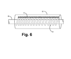
As illustrated in FIG. 6 , tubing 50, e.g., made of FEP (Fluorinated Ethylene Propylene), having an internal diameter larger than the helical coil 51 of the defibrillation electrode 12, is provided to cover the electrode 12. In certain embodiments, the size ratio of the tubing 50 compared to the helical coil 51 is about 3:1. In more particular embodiments, the ratio is about 2:1, and in even more particular embodiments, the ratio is about 1.6:1. The internal diameter of the tubing 50, in certain embodiments, is about 0.125 inch. The longitudinal ends of the tubing 50 are trimmed to a certain length so that the tubing 50 can cover the helical coil 51. Following the dispensing of the material 6 on the helical coil 51, the tubing 50 is subsequently slid over the coil 51 as shown so as to encase the coil 51 (save for the open ends of the tubing 50).
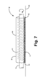
As shown in FIG. 7 , the assembly 58 including the helical coil 51 and the tubing 50 is then placed on a flat rigid surface 60 with an outer portion 62 of the tubing 50 (e.g., opposite an inner portion 61 of the tubing 50 in proximity to the material 6 on the coil 51) contacting the surface 60. A downward vertical force is then applied on the non-contacting portion 64 of the tubing 50 to ensure that the inner portion 61 of the tubing 50 contacts the helical coil 51 with the bead of material 6. While maintaining the downward vertical force on the tubing 50, the assembly 58 is rolled horizontally across the flat surface 60 to distribute the material 6 evenly across the peripheral surface of the helical coil 51 contained within the tubing 50.
During this rolling procedure, the tubing 50 may stick in one position due to the material 6 clumping on one side of the helical coil 51. As such, in certain embodiments, the assembly 58 may need to be flipped so that the non-contacting portion 64 of the tubing 50 contacts the flat rigid surface 60. Applying a vertical downward force on the opposing side of the tubing 50 while rolling the tubing 50 horizontally should enable the material 6 to be subsequently displaced over any non-covered portions of the helical coil 51.
Once the material 6 is evenly distributed over the helical coil 51, the assembly 58 is cured. As should be appreciated, the curing of the assembly 58 can be accomplished using any of a number of known methods. One of these methods includes heat curing. When the silicone adhesives are heat cured, in certain embodiments, the assembly 58 is cured using a heat gun. The heat gun is directed at the assembly 58, with the heat gradually applied along the length of the assembly 58 while the assembly 58 is rotated. In certain embodiments, the heat gun is set at a temperature of about 550° F. and is directed at the assembly for a duration of five minutes. While the heat gun is set at a temperature of about 550° F., the heat gun is generally used with a nozzle extension. As such, the temperature achieved outside of the nozzle extension is typically about 375° F., generally found to be a suitable temperature for shrinking the tubing 50 of the assembly 58. It should be appreciated that both the temperature and time parameters can be adjusted accordingly without departing from the spirit of the invention. For example, if the heat gun is set at a temperature lower than 550° F., then the curing period can, in turn, be conducted for a duration greater than five minutes. As shown in FIG. 8 , following this curing or heating operation, the tubing 50 shall have decreased in size or shrunk so that its inner diameter generally comes in contact with the outer diameter of the helical coil 51. As a result, the material 6 is distributed evenly between the individual coils of the helical coil 51. In certain embodiments, the outer peripheries of the material 6 shall be distributed about the helical coil 51 so as to generally form an isodiametric assembly.
Subsequently, the assembly 58 can be allowed to cool; however, in certain embodiments, this cooling step can be eliminated altogether. The tubing 50 is removed so that a structure 66 defined by the helical coil 51 and the material 6 is exposed. In certain embodiments, the tubing 50 can be removed using a razor blade. As illustrated in FIG. 9 , once the tubing 50 is removed, one can see that the structure 66 is generally isodiametric, wherein the diameters of the material 6 and the helical coil 51 (measured by the outer peripheries of each of the material 6 and the helical coil 51) differ by thousandths of an inch. In certain embodiments, the diameters of the material 6 and the helical coil 51 differ by no more than two thousandths of an inch (0.002 inches).
In certain embodiments, the backfilling process is modified so as to create a defibrillation electrode having an overmolded or overcoated electrode surface. As such, the defibrillation electrode is produced so as to have the material 6 entirely cover the helical coil 51. This structure can be provided by modifying the process described above. In certain embodiments, a greater amount of material 6 is dispensed within the assembly 58 per the syringe 52 and the heating procedure is modified so that the tubing 50 shrinks to a resulting inner diameter that is larger than that previously described herein (the tubing 50 is not shrunk enough to generally create contact between the tubing 50 and the outer periphery of the helical coil 51). One consequence of using an overmolded electrode surface is that the geometric surface area of the resulting electrode is reduced; however, a smooth atraumatic electrode surface is created. As such, the electrode surface can greatly reduce fibrotic encapsulation and improve extractability of the lead. One particular application for this design is the creation of an ultra-long defibrillation electrode from the RV apex to the mid RA chamber (generally about 10-14 cm long), creating a very large shadow area or electric field to reduce defibrillation energy. Previous lead designs have not traversed the tricuspid valve with a defibrillation electrode for fear of possibly damaging the valve leaflet and function.
In certain embodiments, the backfilling process is modified to incorporate carbon nanotubes onto the helical coil 51. The carbon nanotubes will further aid in masking the exposed outer periphery of the helical coil 51. As such, addition of the carbon nanotubes will further prevent fibrous ingrowth on the exposed portions of the helical coil 51 and aid in the extractability of the lead 8, while still being able to provide a delivery of a defibrillation shock through the carbon nanotubes. In certain embodiments, the helical coil 51 is dipped in carbon nanotube powder 68 prior to the tubing 50 being placed over the helical coil 51. As shown in FIG. 10 , following the process steps involving dispensing the material 6, evenly distributing the material 6 within the assembly 58, curing the assembly 58, and removing the tubing 50 from the assembly 58, the carbon nanotube powder 68 shall remain on the exposed surface area of the helical coil 51 of the defibrillation electrode.
In certain embodiments, the material 6 can alternatively be moisture cured. As such, once dispersed on the helical coil 51, the material 6 can be cured with controlled moisture levels at room temperature. As is known, using such a curing procedure, the molding process needs to be designed with particularity to ensure enough moisture is diffused into the composite levels. Such curing techniques will generally not require use of the tubing 50; however, other known methods of distributing the material 6 evenly with respect to the individual coils of the helical coil 51 would need to be initially utilized prior to curing the material 6. Other curing processes are also possible depending on the curing process needed by the polymer components.
It will be appreciated the embodiments of the invention can take many forms. The true essence and spirit of the embodiments of the invention are defined in the appended claims, and it is not intended the embodiment of the invention presented herein should limit the scope thereof.
Claims (7)
1. A method of fabricating a medical electrical electrode comprising:
sliding an elongated conductive coil over a length of a lead body;
dispensing an electrically conductive polymer material on the elongated conductive coil, wherein dispensing the electrically conductive polymer material further includes injecting the electrically conductive polymer material from a syringe;
disposing a tubing over the elongated conductive coil;
distributing the electrically conductive polymer material between individual turns of the elongated conductive coil such that the electrically conductive polymer material is in electrical contact with the elongated conductive coil;
heating the tubing so the tubing shrinks around the elongated conductive coil; and
removing the tubing.
2. The method of claim 1 , wherein the tubing is sized to encase the elongated conductive coil.
3. The method of claim 1 wherein the tubing comprises fluorinated ethylene propylene.
4. The method of claim 1 wherein the size ratio of the tubing to the elongated conductive coil is no greater than about 3:1.
5. A method of fabricating a medical electrical electrode comprising:
sliding an elongated conductive coil over a length of a lead body;
dispensing an electrically conductive polymer material on the elongated conductive coil;
disposing a tubing over the elongated conductive coil;
distributing the electrically conductive polymer material between individual turns of the elongated conductive coil such that the electrically conductive polymer material is in electrical contact with the elongated conductive coil, wherein distributing the electrically conductive polymer material further includes rolling the tubing over a flat surface such that the electrically conductive polymer material flows between the individual turns of the elongated conductive coil;
heating the tubing so the tubing shrinks around the elongated conductive coil; and
removing the tubing.
6. The method of claim 5 , wherein heating the tubing further includes heating the tubing to a temperature of about 375° F. and heating the tubing for about five minutes.
7. The method of claim 5 , wherein heating the tubing further includes shrinking the tubing so the tubing contacts individual coils of the elongated conductive coil.
Priority Applications (1)
| Application Number | Priority Date | Filing Date | Title |
|---|---|---|---|
| US12/414,265 US8831748B2 (en) | 2005-04-25 | 2009-03-30 | Medical electrical electrodes with conductive polymer |
Applications Claiming Priority (2)
| Application Number | Priority Date | Filing Date | Title |
|---|---|---|---|
| US11/113,867 US7512447B2 (en) | 2005-04-25 | 2005-04-25 | Medical electrical electrodes with conductive polymer |
| US12/414,265 US8831748B2 (en) | 2005-04-25 | 2009-03-30 | Medical electrical electrodes with conductive polymer |
Related Parent Applications (1)
| Application Number | Title | Priority Date | Filing Date |
|---|---|---|---|
| US11/113,867 Continuation US7512447B2 (en) | 2005-04-25 | 2005-04-25 | Medical electrical electrodes with conductive polymer |
Publications (2)
| Publication Number | Publication Date |
|---|---|
| US20090187236A1 US20090187236A1 (en) | 2009-07-23 |
| US8831748B2 true US8831748B2 (en) | 2014-09-09 |
Family
ID=36746283
Family Applications (2)
| Application Number | Title | Priority Date | Filing Date |
|---|---|---|---|
| US11/113,867 Active 2025-08-31 US7512447B2 (en) | 2005-04-25 | 2005-04-25 | Medical electrical electrodes with conductive polymer |
| US12/414,265 Active 2027-05-14 US8831748B2 (en) | 2005-04-25 | 2009-03-30 | Medical electrical electrodes with conductive polymer |
Family Applications Before (1)
| Application Number | Title | Priority Date | Filing Date |
|---|---|---|---|
| US11/113,867 Active 2025-08-31 US7512447B2 (en) | 2005-04-25 | 2005-04-25 | Medical electrical electrodes with conductive polymer |
Country Status (7)
| Country | Link |
|---|---|
| US (2) | US7512447B2 (en) |
| EP (1) | EP1888163B1 (en) |
| JP (1) | JP2008538997A (en) |
| AT (1) | ATE486627T1 (en) |
| CA (1) | CA2605705A1 (en) |
| DE (1) | DE602006018000D1 (en) |
| WO (1) | WO2006115902A2 (en) |
Families Citing this family (60)
| Publication number | Priority date | Publication date | Assignee | Title |
|---|---|---|---|---|
| WO2007115198A2 (en) * | 2006-03-31 | 2007-10-11 | Advanced Neuromodulation Systems, Inc. | Compliant electrical stimulation leads and methods of fabrication |
| US7917229B2 (en) | 2006-08-31 | 2011-03-29 | Cardiac Pacemakers, Inc. | Lead assembly including a polymer interconnect and methods related thereto |
| US20080147158A1 (en) * | 2006-12-18 | 2008-06-19 | Quan Emerteq Corp. | Implantable Medical Lead Having Coil Electrode |
| US20080183261A1 (en) * | 2007-01-31 | 2008-07-31 | Cardiac Pacemakers, Inc. | Fibrosis-limiting material attachment |
| US9265936B2 (en) * | 2008-05-07 | 2016-02-23 | Cardiac Pacemakers, Inc. | Lead assembly and related methods |
| US8401669B2 (en) * | 2008-05-07 | 2013-03-19 | Cardiac Pacemakers, Inc. | Lead assembly and related methods |
| US8639356B2 (en) | 2008-05-07 | 2014-01-28 | Cardiac Pacemakers, Inc. | Lead assembly and related methods |
| US20090287285A1 (en) * | 2008-05-07 | 2009-11-19 | Lynn Mark C | Lead assembly and related methods |
| US8141246B2 (en) * | 2008-06-20 | 2012-03-27 | Cardiac Pacemakers, Inc. | Methods and devices for joining cables |
| US8219209B2 (en) | 2008-08-15 | 2012-07-10 | Cardiac Pacemakers, Inc. | Implantable medical lead having reduced dimension tubing transition |
| EP2364177A1 (en) * | 2008-11-14 | 2011-09-14 | Cardiac Pacemakers, Inc. | Eptfe fill of coil filar gaps |
| US8250754B2 (en) * | 2008-11-29 | 2012-08-28 | Medtronic, Inc. | Method of manufacturing a medical electrical lead with insert-molded electrode |
| US8437864B2 (en) * | 2008-11-29 | 2013-05-07 | Medtronic, Inc. | Medical electrical lead with embedded electrode sub-assembly |
| US20100137964A1 (en) | 2008-11-29 | 2010-06-03 | Medtronic, Inc. | Medical electrical lead joints and methods of manufacture |
| US20100133003A1 (en) * | 2008-11-29 | 2010-06-03 | Medtronic, Inc. | Implantable medical electrical leads including coil electrodes |
| US8442650B2 (en) * | 2008-11-29 | 2013-05-14 | Medtronic, Inc. | Medical electrical lead with backfilled electrode sub-assembly |
| US8285395B2 (en) * | 2008-11-29 | 2012-10-09 | Medtronic, Inc. | Conductive couplings, and components thereof, for medical electrical leads |
| US8649878B2 (en) | 2009-06-19 | 2014-02-11 | Greatbatch Ltd. | Temporary stimulation lead with polymer electrodes and method of manufacture |
| US20110021899A1 (en) * | 2009-07-23 | 2011-01-27 | Surmodics, Inc. | Conductive polymer coatings |
| US8380325B2 (en) * | 2009-08-05 | 2013-02-19 | Boston Scientific Neuromodulation Corporation | Systems and methods for coupling coiled conductors to conductive contacts of an electrical stimulation system |
| US8355770B2 (en) * | 2010-03-22 | 2013-01-15 | Idt Technology Limited | Conductive silicone material for human skin electrode |
| EP2568904B1 (en) | 2010-05-10 | 2019-10-02 | Spinal Modulation Inc. | Device for reducing migration |
| CN103093859B (en) * | 2011-10-28 | 2015-08-26 | 清华大学 | Pacing lead and pacemaker |
| CN103093865B (en) * | 2011-10-28 | 2015-06-03 | 清华大学 | Pacemaker electrode line and pacemaker |
| CN103083806B (en) | 2011-10-28 | 2016-06-08 | 清华大学 | Pacing lead and pacemaker |
| CN103083807B (en) | 2011-10-28 | 2016-04-27 | 清华大学 | The preparation method of pacing lead |
| CN103093858B (en) | 2011-10-28 | 2016-10-19 | 清华大学 | Pacing lead and pacemaker |
| CN103083808B (en) * | 2011-10-28 | 2016-04-27 | 清华大学 | Pacing lead and pacemaker |
| CN103093857B (en) * | 2011-10-28 | 2016-04-13 | 清华大学 | Electrode wires and apply the pacemaker of this electrode wires |
| JP6301926B2 (en) | 2012-08-09 | 2018-03-28 | ユニバーシティ オブ アイオワ リサーチ ファウンデーション | Catheter, catheter system, and method for piercing tissue structure |
| EP3091921B1 (en) | 2014-01-06 | 2019-06-19 | Farapulse, Inc. | Apparatus for renal denervation ablation |
| EP3091925A1 (en) * | 2014-01-06 | 2016-11-16 | Iowa Approach Inc. | Devices and methods for delivering therapeutic electrical impulses |
| US9764139B2 (en) | 2014-01-24 | 2017-09-19 | Medtronic, Inc. | Pre-implant detection |
| JP6488088B2 (en) * | 2014-03-28 | 2019-03-20 | マイクロプラズマ株式会社 | Electrode for generating low voltage plasma and plasma irradiation method using the same |
| US9757555B2 (en) | 2014-04-24 | 2017-09-12 | Medtronic, Inc. | Pre-molded sub-assemblies for implantable medical leads |
| WO2015171921A2 (en) | 2014-05-07 | 2015-11-12 | Mickelson Steven R | Methods and apparatus for selective tissue ablation |
| WO2015192018A1 (en) | 2014-06-12 | 2015-12-17 | Iowa Approach Inc. | Method and apparatus for rapid and selective tissue ablation with cooling |
| EP3154463B1 (en) | 2014-06-12 | 2019-03-27 | Farapulse, Inc. | Apparatus for rapid and selective transurethral tissue ablation |
| WO2016060983A1 (en) | 2014-10-14 | 2016-04-21 | Iowa Approach Inc. | Method and apparatus for rapid and safe pulmonary vein cardiac ablation |
| JP6786584B2 (en) * | 2015-07-15 | 2020-11-18 | テレフレックス メディカル インコーポレイテッド | Conductive tip catheter |
| EP3352849A1 (en) * | 2015-09-22 | 2018-08-01 | Sorin CRM SAS | A method of manufacturing an implantable defibrillation coil |
| US10172673B2 (en) | 2016-01-05 | 2019-01-08 | Farapulse, Inc. | Systems devices, and methods for delivery of pulsed electric field ablative energy to endocardial tissue |
| US10130423B1 (en) | 2017-07-06 | 2018-11-20 | Farapulse, Inc. | Systems, devices, and methods for focal ablation |
| US10660702B2 (en) | 2016-01-05 | 2020-05-26 | Farapulse, Inc. | Systems, devices, and methods for focal ablation |
| US10512505B2 (en) | 2018-05-07 | 2019-12-24 | Farapulse, Inc. | Systems, apparatuses and methods for delivery of ablative energy to tissue |
| US20170189097A1 (en) | 2016-01-05 | 2017-07-06 | Iowa Approach Inc. | Systems, apparatuses and methods for delivery of ablative energy to tissue |
| WO2017218734A1 (en) | 2016-06-16 | 2017-12-21 | Iowa Approach, Inc. | Systems, apparatuses, and methods for guide wire delivery |
| US9987081B1 (en) | 2017-04-27 | 2018-06-05 | Iowa Approach, Inc. | Systems, devices, and methods for signal generation |
| US10617867B2 (en) | 2017-04-28 | 2020-04-14 | Farapulse, Inc. | Systems, devices, and methods for delivery of pulsed electric field ablative energy to esophageal tissue |
| EP3681391A1 (en) | 2017-09-12 | 2020-07-22 | Farapulse, Inc. | Systems, apparatuses, and methods for ventricular focal ablation |
| CN116327352A (en) | 2018-05-07 | 2023-06-27 | 波士顿科学医学有限公司 | Epicardial ablation catheter |
| WO2019217317A1 (en) | 2018-05-07 | 2019-11-14 | Farapulse, Inc. | Systems, apparatuses, and methods for filtering high voltage noise induced by pulsed electric field ablation |
| US11291833B2 (en) | 2018-05-09 | 2022-04-05 | Medtronic, Inc. | Bonding strip for fixing an electrode coil to a lead body |
| JP2022501112A (en) | 2018-09-20 | 2022-01-06 | ファラパルス,インコーポレイテッド | Systems, devices, and methods for the delivery of pulsed field ablation energy to endocardial tissue |
| US11590320B2 (en) | 2019-04-04 | 2023-02-28 | Avent, Inc. | Two-in-one catheter and signal generating apparatus |
| US10625080B1 (en) | 2019-09-17 | 2020-04-21 | Farapulse, Inc. | Systems, apparatuses, and methods for detecting ectopic electrocardiogram signals during pulsed electric field ablation |
| US11065047B2 (en) | 2019-11-20 | 2021-07-20 | Farapulse, Inc. | Systems, apparatuses, and methods for protecting electronic components from high power noise induced by high voltage pulses |
| US11497541B2 (en) | 2019-11-20 | 2022-11-15 | Boston Scientific Scimed, Inc. | Systems, apparatuses, and methods for protecting electronic components from high power noise induced by high voltage pulses |
| US10842572B1 (en) | 2019-11-25 | 2020-11-24 | Farapulse, Inc. | Methods, systems, and apparatuses for tracking ablation devices and generating lesion lines |
| CN116487183B (en) * | 2023-06-14 | 2023-10-13 | 苏州维伟思医疗科技有限公司 | Method and device for processing defibrillation electrode |
Citations (8)
| Publication number | Priority date | Publication date | Assignee | Title |
|---|---|---|---|---|
| US3815611A (en) * | 1971-11-26 | 1974-06-11 | Medtronic Inc | Muscle stimulation and/or contraction detection device |
| US4934049A (en) * | 1989-07-07 | 1990-06-19 | Medtronic, Inc. | Method for fabrication of a medical electrode |
| US5115818A (en) * | 1990-02-14 | 1992-05-26 | Medtronic, Inc. | Implantable electrode |
| US5580699A (en) * | 1994-08-16 | 1996-12-03 | Ventritex, Inc. | Method for manufacturing implantable cardiac defibrillation electrodes using a laser beam material removal process |
| US5676784A (en) * | 1995-03-15 | 1997-10-14 | Abbott Laboratories | Method of fabricating a heater coil for a catheter used to monitor cardiac output |
| US5791036A (en) * | 1996-12-23 | 1998-08-11 | Schneider (Usa) Inc | Catheter transition system |
| US20030139794A1 (en) * | 2002-01-18 | 2003-07-24 | Jenney Christopher R. | Body implantable lead including one or more conductive polymer electrodes and methods for fabricating same |
| US20050203604A1 (en) * | 2002-12-06 | 2005-09-15 | Brabec Scott J. | Medical devices incorporating carbon nanotube material and methods of fabricating same |
Family Cites Families (15)
| Publication number | Priority date | Publication date | Assignee | Title |
|---|---|---|---|---|
| US4161952A (en) * | 1977-11-01 | 1979-07-24 | Mieczyslaw Mirowski | Wound wire catheter cardioverting electrode |
| US5016645A (en) * | 1987-06-18 | 1991-05-21 | Terrell Williams | Medical electrode lead |
| JP2753722B2 (en) * | 1988-12-23 | 1998-05-20 | ジャパンゴアテックス株式会社 | Biological electrode |
| US5173362A (en) * | 1991-02-01 | 1992-12-22 | Globe-Union, Inc. | Composite substrate for bipolar electrodes |
| US5347708A (en) * | 1993-09-21 | 1994-09-20 | Medtronic, Inc. | Method for fabrication of implantable electrode |
| US5488768A (en) * | 1993-09-24 | 1996-02-06 | Ventritex, Inc. | Method of forming a defibrillation electrode connection |
| US5584873A (en) * | 1995-05-08 | 1996-12-17 | Medtronic, Inc. | Medical lead with compression lumens |
| US6026567A (en) * | 1995-05-11 | 2000-02-22 | Medtronic, Inc. | Medical lead with stranded conductors |
| US5676694A (en) * | 1996-06-07 | 1997-10-14 | Medtronic, Inc. | Medical electrical lead |
| US5755762A (en) * | 1996-06-14 | 1998-05-26 | Pacesetter, Inc. | Medical lead and method of making and using |
| US6785576B2 (en) * | 1997-04-21 | 2004-08-31 | Medtronic, Inc. | Medical electrical lead |
| US6295474B1 (en) * | 1998-03-13 | 2001-09-25 | Intermedics Inc. | Defibrillator housing with conductive polymer coating |
| US20050004642A1 (en) * | 1998-11-09 | 2005-01-06 | Medtronic, Inc. | Implantable medical lead including overlay |
| US6301507B1 (en) * | 2000-01-20 | 2001-10-09 | Medtronic, Inc | Medical electrical lead having pre-formed atrial section |
| US20040186545A1 (en) * | 2003-03-20 | 2004-09-23 | Rosero Spencer Z. | Temporary percutaneous cardioverter-defibrillator |
-
2005
- 2005-04-25 US US11/113,867 patent/US7512447B2/en active Active
-
2006
- 2006-04-17 DE DE602006018000T patent/DE602006018000D1/en active Active
- 2006-04-17 EP EP06750556A patent/EP1888163B1/en not_active Not-in-force
- 2006-04-17 JP JP2008508912A patent/JP2008538997A/en not_active Withdrawn
- 2006-04-17 CA CA002605705A patent/CA2605705A1/en not_active Abandoned
- 2006-04-17 AT AT06750556T patent/ATE486627T1/en not_active IP Right Cessation
- 2006-04-17 WO PCT/US2006/014549 patent/WO2006115902A2/en active Application Filing
-
2009
- 2009-03-30 US US12/414,265 patent/US8831748B2/en active Active
Patent Citations (8)
| Publication number | Priority date | Publication date | Assignee | Title |
|---|---|---|---|---|
| US3815611A (en) * | 1971-11-26 | 1974-06-11 | Medtronic Inc | Muscle stimulation and/or contraction detection device |
| US4934049A (en) * | 1989-07-07 | 1990-06-19 | Medtronic, Inc. | Method for fabrication of a medical electrode |
| US5115818A (en) * | 1990-02-14 | 1992-05-26 | Medtronic, Inc. | Implantable electrode |
| US5580699A (en) * | 1994-08-16 | 1996-12-03 | Ventritex, Inc. | Method for manufacturing implantable cardiac defibrillation electrodes using a laser beam material removal process |
| US5676784A (en) * | 1995-03-15 | 1997-10-14 | Abbott Laboratories | Method of fabricating a heater coil for a catheter used to monitor cardiac output |
| US5791036A (en) * | 1996-12-23 | 1998-08-11 | Schneider (Usa) Inc | Catheter transition system |
| US20030139794A1 (en) * | 2002-01-18 | 2003-07-24 | Jenney Christopher R. | Body implantable lead including one or more conductive polymer electrodes and methods for fabricating same |
| US20050203604A1 (en) * | 2002-12-06 | 2005-09-15 | Brabec Scott J. | Medical devices incorporating carbon nanotube material and methods of fabricating same |
Also Published As
| Publication number | Publication date |
|---|---|
| EP1888163B1 (en) | 2010-11-03 |
| DE602006018000D1 (en) | 2010-12-16 |
| WO2006115902A2 (en) | 2006-11-02 |
| JP2008538997A (en) | 2008-11-13 |
| US20060241734A1 (en) | 2006-10-26 |
| CA2605705A1 (en) | 2006-11-02 |
| ATE486627T1 (en) | 2010-11-15 |
| WO2006115902A3 (en) | 2007-02-01 |
| EP1888163A2 (en) | 2008-02-20 |
| US7512447B2 (en) | 2009-03-31 |
| US20090187236A1 (en) | 2009-07-23 |
Similar Documents
| Publication | Publication Date | Title |
|---|---|---|
| US8831748B2 (en) | Medical electrical electrodes with conductive polymer | |
| US5542173A (en) | Method of making flexible defibrillation electrode | |
| EP2376179B1 (en) | Implantable lead | |
| US6999821B2 (en) | Body implantable lead including one or more conductive polymer electrodes and methods for fabricating same | |
| US9446232B2 (en) | Implantable lead | |
| US5330520A (en) | Implantable electrode and sensor lead apparatus | |
| US5488768A (en) | Method of forming a defibrillation electrode connection | |
| US5957970A (en) | Method of fabricating a medical electrical lead | |
| US7711437B1 (en) | Lead fixation device | |
| US20070276458A1 (en) | Novel medical device conductor junctions | |
| US8250754B2 (en) | Method of manufacturing a medical electrical lead with insert-molded electrode | |
| US7280875B1 (en) | High strength, low resistivity electrode | |
| EP1666086B1 (en) | Automatic capture pacing lead | |
| EP1793889A1 (en) | Implantable medical lead including overlay | |
| US8442650B2 (en) | Medical electrical lead with backfilled electrode sub-assembly | |
| US6990378B1 (en) | Abrasion-resistant implantable medical lead and a method of fabricating such a lead | |
| US20100125321A1 (en) | Eptfe fill of coil filar gaps | |
| AU2013206194B2 (en) | Implantable lead |
Legal Events
| Date | Code | Title | Description |
|---|---|---|---|
| STCF | Information on status: patent grant |
Free format text: PATENTED CASE |
|
| CC | Certificate of correction | ||
| MAFP | Maintenance fee payment |
Free format text: PAYMENT OF MAINTENANCE FEE, 4TH YEAR, LARGE ENTITY (ORIGINAL EVENT CODE: M1551) Year of fee payment: 4 |
|
| MAFP | Maintenance fee payment |
Free format text: PAYMENT OF MAINTENANCE FEE, 8TH YEAR, LARGE ENTITY (ORIGINAL EVENT CODE: M1552); ENTITY STATUS OF PATENT OWNER: LARGE ENTITY Year of fee payment: 8 |