US8832523B2 - Multi-state symbol error correction in matrix based codes - Google Patents
Multi-state symbol error correction in matrix based codes Download PDFInfo
- Publication number
- US8832523B2 US8832523B2 US12/400,900 US40090009A US8832523B2 US 8832523 B2 US8832523 B2 US 8832523B2 US 40090009 A US40090009 A US 40090009A US 8832523 B2 US8832523 B2 US 8832523B2
- Authority
- US
- United States
- Prior art keywords
- state
- symbols
- error
- check
- errors
- Prior art date
- Legal status (The legal status is an assumption and is not a legal conclusion. Google has not performed a legal analysis and makes no representation as to the accuracy of the status listed.)
- Expired - Fee Related, expires
Links
Images


Classifications
-
- H—ELECTRICITY
- H03—ELECTRONIC CIRCUITRY
- H03M—CODING; DECODING; CODE CONVERSION IN GENERAL
- H03M13/00—Coding, decoding or code conversion, for error detection or error correction; Coding theory basic assumptions; Coding bounds; Error probability evaluation methods; Channel models; Simulation or testing of codes
- H03M13/29—Coding, decoding or code conversion, for error detection or error correction; Coding theory basic assumptions; Coding bounds; Error probability evaluation methods; Channel models; Simulation or testing of codes combining two or more codes or code structures, e.g. product codes, generalised product codes, concatenated codes, inner and outer codes
-
- G—PHYSICS
- G06—COMPUTING; CALCULATING OR COUNTING
- G06F—ELECTRIC DIGITAL DATA PROCESSING
- G06F11/00—Error detection; Error correction; Monitoring
- G06F11/07—Responding to the occurrence of a fault, e.g. fault tolerance
- G06F11/08—Error detection or correction by redundancy in data representation, e.g. by using checking codes
- G06F11/10—Adding special bits or symbols to the coded information, e.g. parity check, casting out 9's or 11's
- G06F11/1008—Adding special bits or symbols to the coded information, e.g. parity check, casting out 9's or 11's in individual solid state devices
- G06F11/1072—Adding special bits or symbols to the coded information, e.g. parity check, casting out 9's or 11's in individual solid state devices in multilevel memories
-
- G—PHYSICS
- G06—COMPUTING; CALCULATING OR COUNTING
- G06F—ELECTRIC DIGITAL DATA PROCESSING
- G06F11/00—Error detection; Error correction; Monitoring
- G06F11/07—Responding to the occurrence of a fault, e.g. fault tolerance
- G06F11/08—Error detection or correction by redundancy in data representation, e.g. by using checking codes
- G06F11/10—Adding special bits or symbols to the coded information, e.g. parity check, casting out 9's or 11's
- G06F11/1008—Adding special bits or symbols to the coded information, e.g. parity check, casting out 9's or 11's in individual solid state devices
- G06F11/1012—Adding special bits or symbols to the coded information, e.g. parity check, casting out 9's or 11's in individual solid state devices using codes or arrangements adapted for a specific type of error
- G06F11/1028—Adjacent errors, e.g. error in n-bit (n>1) wide storage units, i.e. package error
Definitions
- the present invention relates to correction of one or more multi-state symbols in error in a sequence of symbols which can be ordered in a matrix. More specifically, it relates to error correction by first identifying the location of possible errors in a matrix of multi-state symbols, followed by reconstruction of the original symbols from the remaining symbols believed to be not in error.
- Error correction in a plurality of multi-state symbols or a sequence of binary symbols representing multi-state symbols is known, especially in the field of communications and information storage or transfer.
- a series of symbols that is being transferred may have experienced interference or noise on a transmission channel.
- the storage medium, such as an optical or magnetic disk may have been damaged.
- a received sequence of multi-state symbols may be different from the sequence from which it originated. The difference between an original sequence of symbols and a received sequence may be considered to be errors.
- Error control measures can be applied to detect and to correct errors. These measures in general comprise adding additional symbols to a sequence, based on the existing symbols in the original sequence. The redundancy of symbols allows for detection and sometimes correction of errors.
- Error-correction techniques for symbols in a sequence attempt to achieve the best result with as few redundant symbols as possible, and with as limited processing requirements and memory or storage requirements as possible. Error correcting redundancy is usually set to address some maximum or optimal expected symbol error ratio. If information is coded into codewords, it is to be expected that many codewords are error-free and in error-free codewords extra symbols provided for error correction or detection are truly redundant.
- error correcting codes like Reed Solomon codes, which is multi-state based, that k extra symbols, which can be called check symbols, may allow at most 1 ⁇ 2k symbols in error to be corrected.
- Arranging of data symbols in a matrix such as a 2 dimensional matrix is known.
- columns and rows may for instance represent a Reed Solomon codeword.
- Such a code is called a product code.
- a product code still has the disadvantage that redundancy in the codewords is not fully used to determine position of errors and based on the positions of errors in a matrix calculate the correct state for the symbols in error.
- an apparatus for correcting errors in a sequence of k n-state data symbols, an n-state symbol being represented by a signal, with n>2, and k ⁇ 1, comprising, a memory enabled to store instructions, a processor that retrieves and executes instructions from the memory to perform the steps of receiving on an input a plurality of signals representing the sequence of k n-state symbols and p n-state check symbols with p ⁇ k, each of the signals representing p n-state check symbols being generated by an implementation of one of p independent reversible n-state expressions using the k n-state symbols as variables, determining as an independent step which of up to p of the k n-state data symbols are potentially in error and solving as an independent step up to p independent n-state expressions to determine an n-state value for the up to p of the k n-state symbols that are potentially are in error, wherein the solving applies at least an implementation of an n-state
- the apparatus as provided further comprises instructions to perform receiving on the input one or more signals representing one or more check-the-check symbols to correct an error in one or more of the p n-state check symbols.
- the apparatus as provided further comprises instructions to perform receiving on the input one or more signals representing one or more additional sequences of n-state symbols, each additional sequence containing k n-state data symbols and p n-state check symbols, each of the p n-state check symbols being generated by an implementation of one of p independent reversible n-state expressions with the k n-state symbols as variables, receiving on the input signals representing at least q*k n-state check symbols with q ⁇ 1 and q ⁇ p, determining additional n-state data symbols in error by recalculating the n-state check symbols, and solving any additional errors of up to p 2 errors.
- the apparatus wherein a first plurality of n-state check symbols is determined by using a first arrangement of the k n-state data symbols in a first matrix and a second plurality of n-state check symbols is determined by using a second arrangement of the k n-state data symbols in a second matrix.
- the apparatus is provided wherein, p errors have deliberately been introduced as nuisance errors.
- the apparatus is provided, wherein a position of an n-state data symbol in error is known to the apparatus.
- the apparatus is provided, wherein instructions to solve the p errors are provided to the apparatus through a network.
- the apparatus is provided, wherein instructions to solve the p errors are unique to the sequence of k n-state symbols.
- the apparatus is provided, wherein the apparatus is part of a communication system.
- the apparatus is provided, wherein the apparatus is part of at least one of the group consisting of an audio player, a video player, a data storage device, and a communication device.
- a method for by a processor correcting of errors in a sequence of k n-state data symbols, an n-state symbol being represented by a signal, with n>2, and k ⁇ 1, comprising, receiving on an input of the processor a plurality of signals representing the sequence of k n-state symbols and p n-state check symbols with p ⁇ k, each of the signals representing p n-state check symbols being generated by an implementation of one of p independent reversible n-state expressions using the k n-state symbols as variables, determining as an independent step which of up to p of the k n-state data symbols are potentially in error, and solving as an independent step up to p independent n-state expressions to determine an n-state value for the up to p of the k n-state symbols that are potentially are in error, wherein the solving applies at least an implementation of an n-state reversible logic function that is determined by an n by
- the method as provided further comprises receiving on the input one or more signals representing one or more check-the-check symbols to correct an error in one or more of the p n-state check symbols.
- the method as provided further comprises receiving on the input one or more signals representing one or more additional sequences of n-state symbols, each additional sequence containing k n-state data symbols and p n-state check symbols, each of the p n-state check symbols being generated by an implementation of one of p independent reversible n-state expressions with the k n-state symbols as variables, receiving on the input signals representing at least q*k n-state check symbols with q ⁇ 1 and q ⁇ p, determining additional n-state data symbols in error by recalculating the n-state check symbols, and solving any additional errors of up to p 2 errors.
- a first plurality of n-state check symbols is determined by using a first arrangement of the k n-state data symbols in a first matrix and a second plurality of n-state check symbols is determined by using a second arrangement of the k n-state data symbols in a second matrix.
- the method is provided, wherein p errors have been introduced deliberately.
- the method is provided, wherein a position of an n-state data symbol in error is known to the apparatus.
- the method is provided, wherein instructions to solve the p errors are provided to the processor through a network.
- the method is provided, wherein instructions to solve the p errors are unique to the sequence of k n-state symbols.
- the method is provided, wherein the processor is part of at least one of the group consisting of an audio player, a video player, a data storage device, and a communication device.
- the method is provided, wherein the processor is part of a communication system.
- novel methods and system are provided that will correct errors in a sequence of symbols by detecting which symbols are in error and then reconstructing the error symbol by n-state logic expressions with symbols in errors as unknowns.
- a method for coding and decoding of a plurality of n-valued data symbols with n>2, further comprising correcting in a deterministic way up to p ⁇ q ⁇ q errors in the second matrix.
- a method for coding and decoding of a plurality of n-valued data symbols with n>2, further comprising correcting in an iterative way more than p ⁇ q symbols in error.
- a method for coding and decoding of a plurality of n-valued data symbols with n>2, further comprising a second set of check symbols associated with the second matrix, wherein each check symbol in the second set of check symbols is generated from an expression with two or more check symbols generated from n-state data symbols as variables.
- a method for coding and decoding of a plurality of n-valued data symbols with n>2, wherein one or more check symbols generated from n-state data symbols and two or more check symbols from the second set of check symbols form a Reed Solomon codeword.
- a method for coding and decoding of a plurality of n-valued data symbols with n>2, wherein an expression for generating a check symbol is defined in GF(n).
- a method for coding and decoding of a plurality of n-valued data symbols with n>2, wherein an expression is implemented in binary logic.
- a method for coding and decoding of a plurality of n-valued data symbols with n>2, further comprising: determining a magnitude of an error for a symbol in error; and adjusting a symbol in error with the magnitude of the error.
- a system for coding and decoding of a plurality of n-state data symbols with n>2, comprising: a processor enabled to execute instructions upon the n-state data symbols; means to store the instructions; and instructions enabled to perform the steps of: associating the plurality of n-state data symbols with a k-dimensional matrix with k ⁇ 2; generating p check symbols with p ⁇ 1 for q instances with q ⁇ 2 of a first dimension of the first matrix, each check symbol in an instance of a first dimension being generated by applying an n-state logic expression with data symbols as variables; generating q check symbols for a plurality of instances of a second dimension of the k-dimensional matrix, each check symbol in an instance of a second dimension being generated by applying an n-state logic expression with data symbols as variables; associating the plurality of n-valued data symbols and generated check symbols with a second matrix of which the k-dimensional matrix is a sub-matrix and transmitting the steps of: associating the plurality of n
- a system for coding and decoding of a plurality of n-state data symbols with n>2, further comprising correcting in a deterministic way up to p ⁇ q ⁇ q errors in the second matrix.
- a system for coding and decoding of a plurality of n-state data symbols with n>2, further comprising correcting in an iterative way more than p ⁇ q symbols in error.
- a system for coding and decoding of a plurality of n-state data symbols with n>2, further comprising a second set of check symbols associated with the second matrix, wherein each check symbol in the second set of check symbols is generated from an expression with two or more check symbols generated from n-state data symbols as variables.
- a system for coding and decoding of a plurality of n-state data symbols with n>2, wherein one or more check symbols generated from n-state data symbols and two or more check symbols from the second set of check symbols form a Reed Solomon codeword.
- a system for coding and decoding of a plurality of n-state data symbols with n>2, wherein an expression for generating a check symbol is defined in GF(n).
- a system for coding and decoding of a plurality of n-state data symbols with n>2, wherein an expression is implemented in binary logic.
- a system for coding and decoding of a plurality of n-state data symbols with n>2, further comprising: determining a magnitude of an error for a symbol in error; and adjusting a symbol in error with the magnitude of the error.
- a method for coding and decoding of n-state data symbols, an n-state symbol able to assume one of n states with n>2, comprising, associating the n-state data symbols with a k-dimensional matrix with k>2; generating p independent n-state check symbols with q instances of a first dimension of the k-dimensional matrix, generating q independent n-state check symbols with p instances of a second dimension of the k-dimensional matrix; associating the n-state data symbols and check symbols with a second matrix which has the k-dimensional matrix as a sub-matrix; determining that m instances of the first dimension of the k-dimensional matrix are in error with m>p but not more than q instances of the second dimension of the k-dimensional matrix are in error; and solving up to m ⁇ q symbols in error from the second matrix.
- a method for coding and decoding of n-state data symbols, an n-state symbol able to assume one of n states with n>2, further comprising: making a symbol that is in an instance of a first and a second dimension in error of the second matrix an unknown in an equation; and solving q unknowns in an instance of second dimension of the second matrix from a set of q independent equations.
- a method for coding and decoding of n-state data symbols, an n-state symbol able to assume one of n states with n>2, further comprising: determining a magnitude of an error for a symbols in error; and adjusting a symbol in error with the magnitude of the error.
- FIG. 1 is a diagram of a matrix in accordance with an aspect of the present invention.
- FIG. 2 is another diagram of a matrix in accordance with an aspect of the present invention.
- FIG. 3 is a diagram of an equation solver in accordance with an aspect of the present invention.
- FIG. 4 is another diagram of a matrix in accordance with an aspect of the present invention.
- FIG. 5 is yet is another diagram of a matrix in accordance with an aspect of the present invention.
- FIG. 6 is yet is another diagram of a matrix in accordance with an aspect of the present invention.
- FIG. 7 is yet is another diagram of a matrix in accordance with an aspect of the present invention.
- FIG. 8 is yet is another diagram of a matrix in accordance with an aspect of the present invention.
- FIG. 9 illustrates a system that is used to perform the steps described herein in accordance with another aspect of the present invention.
- FIG. 10 illustrates a storage system for writing data to a storage medium in accordance with yet another aspect of the present invention
- FIG. 11 illustrates a storage system for reading data from a storage medium in accordance with yet another aspect of the present invention.
- FIGS. 12 and 13 illustrate an implementation of an n-state truth table.
- an error correcting code is provided for a matrix of multi-state symbols enhanced with check symbols.
- multi-state, n-state, multi-valued and n-valued symbol will mean a symbol which may assume one of 3 or more states, which distinguishes it from binary symbols or bits which can only assume one of 2 states.
- state or value and multi-state or multi-valued will be used interchangeably.
- the logic functions that are provided herein represent the switching of states.
- a state may be represented by a digit or a number. This may create the impression that an actual value is attached to a state.
- One may, to better visualize states, assign a value to a state. However, that is not a requirement for a state.
- a name or designation of a state is just to indicate that it is different from states with different designations. Because some logic functions herein represent an adder the names state and value may be used meaning the same.
- a state may be represented by independent phenomena. For instance, different states of a signal may be represented by different wavelengths of an optical signal. A state may also be represented by a presence of a certain material, by a quantum-mechanical phenomenon, or by any other phenomenon that can distinguish a state from another state.
- a symbol which is regarded herein as a single element, may also be represented by 2 or more p-state symbols wherein p ⁇ n.
- a 4-state symbol may be represented by 2 binary symbols.
- check symbols especially in sequences of binary symbols, is known, and either a parity symbol or a combination of symbols representing a checksum is generated.
- One may also generate n-valued check symbols by applying n-valued symbols to one or more n-valued logic functions. For instance, one may have a sequence of 4 4-valued data symbols [d1 d2 d3 d4].
- One may create a check symbol c (or the fifth symbol in the sequence) by for instance adding modulo-4 the value (or representation of the state of each data symbol) of each data symbol.
- the symbols are n-state, with at this stage no limitation to the number of states (just n>2).
- the functions can be any n-valued switching function, related to the n-state of the symbols.
- an n-valued function for determining a check symbol is preferably a reversible n-valued logic function. While it seems strange, one may also solve equations with non-reversible n-valued logic functions.
- a non-reversible n-valued logic function has a truth table with at least one row or column that has two identical output states for different input states. By providing sufficient different equations one can address the uncertainty related to the states of for instance inputs (x1, x2) and (x1, x3) generating the same output state d1.
- a sequence of 9 multi-state symbols d12, d12, d13, d21, d22, d23, d31, d32 and d33 can be arranged in a 2-dimensional matrix as shown in FIG. 1 having rows and columns.
- Each check symbol is created from data symbols in its respective row or column.
- FIG. 1 is merely an illustrative example.
- a check symbol in a row or a column is shown for illustrative purposes at the end of a row or the bottom of a column. It should be clear that one may position a check symbol anywhere in a matrix as long as one knows from which data symbols a check symbol is determined.
- a sequence of symbols can be arranged in a matrix for analysis and determination of check symbols. It should be clear that the symbols are usually not transmitted in a matrix. One does not have to arrange symbols in an actual matrix for analysis. It is required that one knows the relationships between data symbols and check symbols and how two or more different check symbols may have at least one data symbol in common.
- a preferred embodiment as one aspect of the present invention is to first identify which symbols in a matrix are possibly in error, and based on a selected coding scheme reconstruct the symbols that were detected as being possibly in error by using reversing equations. Assume that in a 2-dimensional matrix each row has p check symbols and each column has q check symbols and no more than q rows or no more than p columns are in error one may solve up to p ⁇ q errors in a deterministic manner.
- a row or a column being in error herein means that a row or a column has at least one check symbol which after being recalculated has a value or state different from its received value.
- each word having 2 ⁇ k check symbols may correct up to k errors.
- solving errors is a relatively complex process. If one can identify location of errors, reconstruction of the symbol in errors is relatively simple.
- Reed Solomon codes may be excessive and use of error detection and symbol reconstruction as provided herein as an aspect of the present invention may be simpler and more effective, achieving a bigger “bang-for-the-buck” so to speak for each check symbol.
- c2 a ⁇ 2b ⁇ 3c ⁇ 2d in an n-valued code.
- n-valued coders with LFSRs either in Galois or in Fibonacci configuration is that each next generated check symbol has an independent equation from another check symbol in the code. That is a reason why Reed Solomon (RS) codes work as error correcting codes.
- RS Reed Solomon
- the advantage of using an LFSR is that one does not need to execute each expression or equation in full to generate a check symbol.
- the appropriate configuration of the LFSR takes care of generating the check symbols in accordance with independent expressions or equations.
- the drawback of the RS code is that the location of an error first has to be found by for instance solving an error correction polynomial. In order to be able to do that for each error there have to be 2 check symbols. By knowing where the errors occur, for instance by using a matrix with error symbols derived from columns and rows, one may be able to use just one check symbol per error.
- One method is to solve the equations in an algebraic fashion. In order to solve equations it is useful to review the rules for reversible, non-commutative and non-associative n-valued logic functions. Assume n-valued logic function ‘sc’ to be reversible, non-commutative and non-associative.
- GF(2 p ) a self reversing, commutative and associative function.
- An LFSR in GF(2 p ) can be realized with functions which are a combination of adders with multipliers to generate check symbols.
- Galois field arithmetic may be preferred for solving the equations for in error symbols. However, these easy solutions may only be available for codewords defined in extension binary fields.
- a 5 symbol 5-valued code will be generated with 3 data symbols and two check symbols generated by using 5-state switching function sc5, which is the mod-5 addition with the following truth table.
- the check symbols can be generated by an LFSR.
- each codeword in a set of codewords must have at least k+1 different symbols in common positions from any other codeword in the set. Or each codeword may at most have (n ⁇ k ⁇ 1) symbols in common positions. The best one can do in a 7 symbol codeword to detect 3 errors is having at most 3 symbols in common.
- Such a code would require 8-valued symbols and is generally known as an RS-code. It is possible to meet the error detection requirement in a lower valued symbol codeword. However, that would require a codeword with more symbols. It is then understood that other and different examples of detection 3 errors in a codeword can be provided according to different aspects of the present invention.
- an 8-valued 7 symbol codeword with 3 check symbols will be provided to demonstrate error correction when the position of errors is known.
- the data symbols occur sequentially as x1 . . . x4, y1 . . . y4, v1 . . . v4, z1 . . . z4.
- the symbols are broken up as 4 columns of 4 data symbols and horizontal check symbols t and tt are generated as well as vertical check symbols p, q, and r.
- the symbols tt are check symbols on the check symbols.
- the assumption in the example is that errors will occur as at most 3 errors in a column.
- One skilled in the art may, of course, design 2 or 3 dimensional matrices for different (also non adjacent) errors and different symbol error ratios as well as different codeword sizes.
- the above check symbols may also be generated by an 8-valued LFSR.
- [x y v] to be in error.
- a partial set of 7 8-valued symbol codeword generated by the above expressions is shown in the following table.
- the set of equations for the above coder will be used.
- Cramer's rule one should apply all additions and multiplications of this example in GF(8).
- Cramer's rule using for other radix-n one should apply the appropriate arithmetic.
- Cramer's rule to other n-valued codes, such as the 5-valued coder of above.
- n-valued adders and multiplications either modulo-n or over GF(n).
- An n-valued multiplication with a constant may be dealt with as an n-valued inverter.
- This reduction may be applied to any expression having inverters and functions, including modulo-n adders and multipliers and adders and multipliers over GF(n).
- an n-valued expression created from adders and having at least one multiplier may be changed to an expression having at least one function not being an adder modulo-n or over GF(n).
- a function not being an adder over GF(n) or a modulo-n adder herein may be defined as an n-valued non-adder function.
- an expression may be part of Cramer's rule.
- FIG. 3 provides a diagram for solving different equations depending on different errors.
- a solution set is determined a stored for instance as an executable program or is hard wired as a circuit. Assume a codeword having 10 data symbols and 3 check symbols and each codeword of the set has at most 9 symbols in common with another codeword. Assume that, for instance, through using also horizontal error check symbols one can determine where errors occur in a column 1000 in FIG. 3 . Assume that errors occurred in position 1001 or in the first 3 symbols of the codeword. The solution for this situation is enabled as ‘solution 1’ in equation solver 1010 .
- This equation solver may be part of a computer program or hard wired logic circuits.
- the solver is then provided with the known correct symbols [x4 x5 x6 x7 x8 x9 x10 p1 p2 p3] and then generates the correct [x1 x2 x3].
- Such a circuit or computer program may calculate a value. This may be achieved by n-valued or n-state circuits or devices. It may also be achieved by binary circuitry, wherein an n-state symbol is represented in binary form. Ultimately, the solver will generate the correct state for the symbols in error.
- the correct symbols may be generated as n-state signals, or in a binary signal representation or in any other signal representation that can be used to represent the corrected symbol.
- a symbol in binary representation may for instance be converted into an n-state signal by applying a Digital/Analog converter as is well known to one of ordinary skill in the art.
- a symbol in binary representation may also be further processed in binary form.
- the complete set of symbols as received and corrected is then available for further processing by digital devices or a processor or any other digital signal processing device. Accordingly, actual devices are used.
- the received and corrected n-valued symbols may be processed an converted and provided by a device into an audio signal. It may also be used to generate a video signal, a radar signal, or any other useful signal.
- the methods and apparatus to correct n-valued signals or representations of n-valued or n-state signals are useful, as they prevent from errors to occur in for instance audio and/or video signals and thus prevent a negative experience by the user of such audio or video signals.
- an apparatus evaluates and/or processes at least 100 n-state check symbols per second.
- an apparatus evaluates and/or processes at least 1000 n-state check symbols per second. In yet another embodiment an apparatus evaluates and/or processes at least 100,000 n-state check symbols per second. In yet another embodiment an apparatus evaluates and/or processes at least one million n-state check symbols per second.
- the solver addresses a different ‘solution 2’ and generates [x5 x6 x7] and for error situation 1003 the solver addresses yet another ‘solution 3’ which may generate just x10 or also [p1 p2] if those symbols are used in a later stage.
- n-state symbols in error can be corrected once their location is known.
- a method is provided to detect multiple errors over a dimension of a matrix and to provide possible locations of symbols in errors. Based on the location one may calculate directly the magnitude of an error (by using a syndrome) or the correct value of a symbol in error.
- a dimension of a matrix such as a row or a column
- a dimension of a matrix contains many data symbols of which only a few are in error it may reduce the number of calculations by first determining a magnitude of an error and then correct the symbol in error by that magnitude.
- a dimension of a matrix such as a row or a column has p check symbols of which each check symbol is generated of an independent equation compared to the other check symbols then always p symbols in error can be detected. Errors in such a case cannot cancel each other out.
- the check symbols are calculated.
- the symbols are then processed, stored or transmitted. After receiving the processed, stored or transmitted symbols the check symbols are recalculated.
- the existence of one and up to p symbols in error in a dimension of a matrix will create at least one recalculated check symbol which is different from a received check symbol.
- the dimension such as a row or column of a matrix is then called in error, and may be called a row, column or dimension in error.
- an error in a data symbol will put at least two dimensions or for instance a row and column in error. Accordingly, an error may exist at the cross point of two dimensions in error.
- check symbols may be in error. If only check symbols are in error one may not care to solve the symbols in errors as the data symbols are correct. If a mix of data symbols and check symbols are in error one may have to solve all errors. It may be advantageous to assure that all check symbols are error free, for instance by applying excess check-the check symbols ‘tt’ for instance by coding the check symbols according to a Reed Solomon (RS) code.
- RS Reed Solomon
- Such use of a RS-code does not fundamentally change the approach herein provided.
- check symbols are error free, possibly by using RS codes. This is shown schematically in FIG. 4 in a matrix code 400 . Herein the data symbols are in 401 .
- the check symbols of the rows are in 402 and of the columns in 403 .
- Check-the check symbols are in 404 .
- the size of block 404 reflects that additional check on check-the check symbols are included to allow error correction in the check symbols. It is to be understood that in a different embodiment one may have errors in check symbols that require correction.
- FIGS. 5 and 6 show a matrix with errors related to the matrix code of FIG. 2 .
- the check-the check symbols ‘tt’ are deliberately omitted in this illustrative example to keep focus on error location, but may be assumed.
- a row of a matrix comprising n-state data symbols may have p independent n-state check symbols.
- a column of the matrix comprising n-state data symbols may have q independent check symbols. If m columns are in error with m>p but not more than q rows are in error one can solve up to m ⁇ q symbols in error by assuming each symbol that is in a row or a column in error as an unknown; by solving q unknowns in a column from a set of q independent equations; and by solving all unknowns for all columns.
- a first dimension of a k-dimensional matrix comprising n-state data symbols may have p independent n-state check symbols.
- a second dimension of the k-dimensional matrix comprising n-state data symbols may have q independent check symbols. If m instances of the first dimension are in error with m>p but not more than q instances of the second dimension are in error one can solve up to m ⁇ q symbols in error by assuming each symbol that is in an instance of a first and a second dimension in error as an unknown; by solving q unknowns in an instance of second dimension from a set of q independent equations; and by solving all unknowns for all instances of a second dimension.
- An instance of a dimension is then a row in that dimension.
- An instance of a first dimension in a 2-dimensional matrix may be a row in horizontal direction, commonly called a row.
- An instance of a second dimension of a 2-dimensional matrix is then a row in the vertical direction or commonly called a column.
- An instance of a third dimension of a 3-dimensional matrix is a row that is perpendicular to the first and second dimensions, etc.
- inv a (x1) means that x1 is modified according to an inverter inv a which is n-valued multiplication by a factor ‘a’.
- Adders over GF(2 p ) are associative, distributive and self reversing. As was shown above, solving equations can easily be achieved with for instance Cramer's rule. Because Cramer's rule will lead to adding of terms which are multiplied by a coefficient, one may in implementation reduce these functions again according to the inverters which represent the multipliers, to reduced functions not being an addition and not having multipliers, thus making execution of an n-valued expression faster.
- n-state switching expressions may look like arithmetical expressions. It is emphasized that these expressions are n-state switching or logic expressions that are to be implemented in devices.
- codewords [x1 x2 x3 x4 s11 s12] which may be part of a code wherein each codeword differs at least in 3 symbols in like positions.
- Codewords with such a property can be generated by LFSRs, but also by direct execution of the expressions as shown above. If one uses an LFSR such an LFSR may be in Galois or Fibonacci configuration. In general Galois configuration LFSRs are used in the literature, however this is not required and Fibonacci configurations may have a speed advantage as one may start generating check symbols directly.
- a Galois LFSR needs to read-in each symbol to generate the correct content of the shift register and then needs to read-out the generated symbols.
- LFSR methods are for instance used in CRC error detection. By using this type of codewords errors in case of two errors in a codeword cannot be hidden by canceling each other out under certain conditions.
- the number of errors will not exceed 3 in a word.
- n is selected for creating codewords that will detect at least p errors and that increases the chance to detect p+1 errors.
- Check symbols may be generated by either executing the above expressions by 8-valued switching functions, or by running an LFSR that will generate [r1 r2 r3], or by executing three 8-valued expressions in a 8-state switching device which are equivalent to the above expressions. It has been shown by the inventor in the earlier cited patent applications that expressions containing a multiplication by a constant and an addition may be reduced to a function not being an addition and containing not a multiplication. Such an equivalent expression may determine a check symbol faster than an expression containing an multiplication. It may be easier to first determine all expressions with multiplications and additions because in GF(8) these functions are commutative, associative and distributive, and reduce the obtained final expressions.
- FIG. 7 shows a matrix code with 3 independent check symbols per column and per row.
- An error situation is shown in FIG. 7 .
- the code is dimensioned in such a way that “illegal” errors which are more than 3 errors in a row or in a column have not occurred.
- an error ‘eij’ is an assumed error, not an actual error.
- the actual errors are indicated as ‘aeij’ and are printed in bold and a larger font in FIG. 7 .
- the positions of the actual errors are of course unknown a priori solving the errors. However the total assumed number of errors can all be resolved using the independent n-valued expressions.
- (x1+e11), (x2+e12), and (x1+e13) are the received values of the data symbols for the position of x1, x2 and x3. It may be assumed that the “error-free” value of a symbol was changed during transmission by a value ‘e’. By inputting these received values in the expressions one can determine the calculated check symbol values. These calculated check value symbols may differ from the received check value symbols by a factor ‘seij’. It was assumed that the received check symbols are error free (or can be made error free by applying a Reed Solomon code, using check symbols over check symbols). Accordingly one can determine what a difference between calculated and received data symbols is.
- each column only will have 3 assumed syndrome errors (of which some will be 0), and these can be calculated directly by solving the set of equations for the syndromes, for instance by applying Cramer's rule.
- x1, x2, x3, and x4 are the consecutive data symbols in a row and the codeword formed by a matrix row is then [x1 x2 x3 x4 s1 s2 s3].
- a column has 5 data symbols and a row has 4 data symbols. Each row and each column have one symbol in common. It is assumed in FIGS. 7 and 8 for illustrative purposes that the check symbols are error free. Check symbols to check the check symbols may be assumed but are not shown and may be part of an RS code for check symbols.
- the following matrix shows the received symbols of which some may be in error and the correct check symbols as calculated before being transmitted (d is a data symbol, c indicates a check symbol).
- a method for error correcting coding and decoding of n-valued symbols in a matrix that has at least 2 dimensions, and wherein over a first dimension (for instance the rows) k independent check symbols are developed and over a second dimension (for instance the columns) p independent check symbols are developed.
- k independent check symbols are developed and over a second dimension (for instance the columns) p independent check symbols are developed.
- One may provide check symbols over check symbols to make sure that after reception the check symbols are error free. As long as the errors in a row do not exceed k and the number of rows with errors does not exceed p, one may be able to correct all errors.
- a code may have better performance than for instance a Reed Solomon product code. It can solve errors fairly easily, by virtue of simple error location detection and simple calculation of error magnitude. If not too many errors occur one can use fewer check symbols than a word coded in RS mode, which of course applies twice as many check symbols.
- the advantage of the RS code is that if the condition of sufficient independent check symbols (assume 2*b) is met one may solve the maximum number of errors (b) for each codeword.
- the method of error correction can error correct at least p ⁇ q symbols if one dimension of the matrix each instance has p check symbols and each instance of the second dimension has q check symbols.
- ‘s’ n-valued check symbols generated by independent sets of equations will detect more than ‘s’ errors. Assume that in a row of data symbols p symbols in error may always be detected. Assume that up to q symbols in error will be detected in a column. Assume that each row has p errors, but there will not be overlap between errors in different rows. One then has to solve p ⁇ q ⁇ q unknowns of which p ⁇ q are errors. However one can easily imagine that the other unknowns are also errors, which have been detected. In that case one may solve up to p ⁇ q ⁇ q errors in a deterministic way.
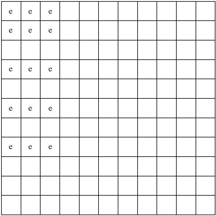
- the coding/decoding method provided above has of course limitations in the number of errors that can be corrected. It is assumed that a dimension has no more errors than can be detected. Such a limitation may be reasonable for instance over the rows, if the sequence of symbols is transmitted as sub-sequent rows. However such a limitation is a disadvantage to the column structure of the matrix. For instance assume an 8 by 8 matrix of data symbols, wherein each row and column is provided with three independently generated check symbols. Assume that at most 3 symbols in error can occur in a row. The following matrix shows an example of how one may still correct errors when more than 3 rows are in error.
- the following matrix shows how both in a column or a row not more than 3 errors occur.
- One assumption may be that at most 3 consecutive errors will ever occur. That means that if more rows are in error than consecutive errors can occur, then there is only partial overlap of errors in rows. In that case also not all rows have overlap.
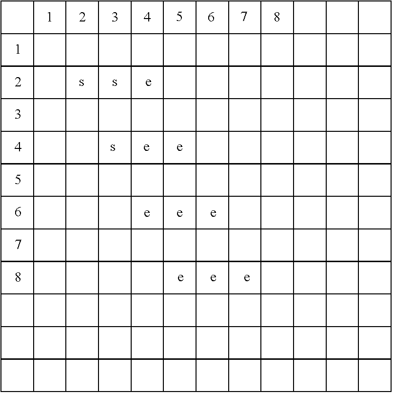
- the solved errors will be named s. Recalculating the check symbols over columns is unreliable, because of the assumption. However recalculation of check symbols over a row will show if one has caught all errors in a row. Accordingly, based on the assumption, one will have cleared the errors in the first rows and one may replace the received symbols with the recalculated symbols. Row 2 will remain in error because column 4 will remain in error. The same reasoning applies to row 4. One may then fill in the correct values for the errors in row 1, and recalculating the check symbols will create the following tableau:
- the iterative method as provided above can also be used wherein the role of columns and rows are exchanged.
- the syndromes are used to calculate the magnitude of the error and then calculate the correct value of the symbol in error.
- the symbols are in error and what the correct value of a check symbol is, one may also directly solve the value of a symbol in error.
- this requires solving more equations and may take more time. There may be situations wherein solving more equations but not having to calculate the correct value from a symbol in error and an error magnitude is actually faster and such situations are fully contemplated as an aspect of the present invention.
- Matlab instruction rref(A) applies common 10-valued arithmetic to all elements of the matrix to wipe the columns. It should be clear that one can adapt such a method to for instance modulo-10 arithmetic. One may adapt the rules also to any other arithmetic over GF(n), which is fully contemplated as an aspect of the present invention. One may also adapt the rule and implement it for error correction for any modulo-n or GF(n) arithmetic.
- the normal decimal instruction rref(A) in Matlab will be applied, with the understanding that the method can be adapted to any n-valued logic.
- the purpose is to show that in a number of cases a sufficient number of independent equations is available to solve the errors.
- each row and each column has two check symbols: r1 and r2 to each row and q1 and q2 to each column.
- + (for illustrative purposes) is the normal addition.
- r1 can be multi-digit.
- the ‘+’ is a logic function which can be an addition over GF(n) such as modulo-n add if appropriate.
- the check symbol will be a single symbol. As was shown above one can solve an equation for such a case.
- the following illustrative example illustrates this approach.
- the symbols xij are the data symbols.
- the symbols si and pj are check symbols determined over rows and columns respectively. One may add check symbols for the check symbols, which may be assumed herein. Assume that one all check symbols are error free after reception. Assume also that x11, x22 and x33 are in error after transmission. This means that check s1, s2, s3, p1, p2 and p3 will indicate an error. This means that one has potentially 9 errors or unknowns that have to be solved, which is not possible.
- the functions F, G, H and I may be different, they may also be identical.
- the following table shows the dependencies of check symbols:
- the column cs shows with an ‘e’ if the check symbol indicates an error.
- the check symbols indicated in the rows containing G, H and I may assumed to be error free.
- the above example shows only the dependency of check symbols with the re-arranged n-state symbols in a matrix.
- the number of n-state-symbols in the first and the second matrix are preferably the same. Strictly speaking, that requirement is not absolutely necessary.
- the check symbols in the second matrix are used for error detection. It should be clear that one can arrange a second matrix and create r ⁇ different and independent check symbols per row or column.
- One may then use the expressions that are used to generate the check symbols to create systems of equations with the expressions of the first matrix to resolve errors.
- One may also create a different third matrix along the lines of the second matrix but with different jumps in index to unhide hidden errors.
- All steps to resolve the errors in a decoder are deterministic, though they can be iterative, by cleaning errors from a row or column in a matrix that has a number of errors that is not greater than the number of check symbols associated with a row or a column. After an error has been resolved in a row of a matrix, it also diminishes the number of errors in the corresponding column of the matrix. This may put the total number of errors in a column in a condition of being equal or smaller than the related number of check symbols, which makes all errors in that column solvable. It also may be the case that by solving an error in a row of a first matrix, the numbers of errors in a row or a column in a related second matrix have become such that the errors have become solvable. It should be clear that while the above approach is illustrated by using errors in a row, it applies to solving errors in a column or in any other dimension in a k-dimensional matrix.
- the selection of the size of a matrix depends among other aspects on the expected number of errors, and if errors are expected to appear in bursts or completely random. Errors may also be introduced deliberately.
- a matrix code is a virtual matrix made up from data symbols and calculated check symbols. In general symbols will not be transmitted as a matrix, but for instance sequentially in a frame of symbols. At the receiving end the virtual matrix can be reconstructed by assigning each symbol in a frame a position in the virtual matrix, which may for instance be stored in an addressable electronic memory.
- the here provided methods and apparatus for error correction by error detection and symbol reconstruction can be used in a system, such as a communication system.
- a communication system may be a wired system or a wireless system.
- Such a system may be used for data transmission, telephony, video or any other type of transfer of information.
- FIG. 9 A diagram of such a system is provided in FIG. 9 .
- 901 is a source of information.
- the information is provided to a coder 902 .
- the information provided to a coder 902 may already be in a digital form. It may also be converted into digital form by the coder 902 .
- the coder 902 creates the code words of a plurality of data symbols with added check symbols as described herein as another aspect of the present invention.
- the codewords are organized in such a way that up to a number of symbols in error can be identified as such.
- the thus created codewords may be provided directly to a medium 903 for transmission. They may also be provided to a modulator/transmitter 906 that will modify the digital coded signal provided by 902 to a form that is appropriate for the medium 903 .
- 906 may create an optical signal, which may be written on an optical disk, or provided to a transmission medium such as an optical fiber.
- Modulator 906 may also be a radio transmitter, which will modulate the signal on for instance a carrier signal, and wherein 903 is a radio connection. Not specifically shown, but assumed, is circuitry as known to one of ordinary skill in the art to provide and insert “housekeeping” signals, which may include synchronization signals or other signals to assist a receiver to receive, demodulate, decode and display a signal.
- a receiver 907 may receive, amplify, and demodulate the signal coming from 903 and provide a digital signal to a decoder 904 .
- the decoder 904 identifies if and which symbols are in error in accordance with another aspect of the present invention and then applies the methods provided herein to correct symbols in error.
- a decoded and error corrected signal is then provided to a target 905 .
- a target may be a radio, a phone, a computer, a tv set or any other device that can be a target for an information signal.
- a coder 902 may also provide additional coding means, for instance to form a concatenated or combined code. In that case, the decoder 904 has equivalent means to decode the additional coding. Additional information, such as synchronization, frame or ID information, may be inserted during the transmission and/or coding process.
- the here provided methods and apparatus for error correcting coding and decoding of signals can also be applied for systems and apparatus for storage of information.
- data stored on a CD, a DVD, a magnetic tape or disk or in mass memory in general may benefit from error correcting coding.
- a system for storing error correcting symbols in accordance with another aspect of the present invention is shown in diagram in FIG. 10 .
- a source 1001 provides the information to be coded. This may be audio, video or any information data. The data may already be presented in n-valued symbols by 1001 or may be coded in such a form by 1002 .
- Unit 1002 also creates the code words of a plurality of data symbols with added check symbols as described herein as another aspect of the present invention.
- Codewords are organized in such a way that up to a number of symbols in error can be identified as such.
- the thus created codewords may be provided directly to a channel 1004 for transmission to an information carrier 1005 .
- a modulator/data writer 1003 will be required to write a signal to a carrier 1005 .
- the channel requires optical signals or it may require magnetic or electromagnetic or electro-optical signals.
- Modulator/data writer 1003 will create a signal that can be written via channel 1004 to a carrier 1005 .
- Important additional information such as for ID and/or synchronization may be added to the data.
- apparatus and methods for error detection and error correction as provided herein may be part of an audio player, a video player, a communication device, a storage device or any other device or system that may benefit from correction of errors in a signal.
- a mobile computing device such as a mobile phone or a personal digital assistant (PDA).
- PDA personal digital assistant
- a storage medium may be an optical disk, a magnetic disk or an electronic medium.
- Such media may store binary symbols and store n-state symbols as binary words such as bytes. It may also store n-state symbols as multi-state symbols, each symbol having one of 3 or more states.
- a computing device implementing one or more of the methods and/or n-state expressions may be connected to a network.
- a network may be a wired or a wireless network.
- the network may be the Internet. It may also be a single connection to another apparatus.
- Communication may take place with binary symbols, analog signals or signals being a multi-state symbol having one of 3 or more states, such as 16-QAM signals or any other signal that can have one of 3 or more states.
- a signal may be an electronic signal, a radio signal, an optical signal, an acoustical signal, a mechanical signal, a quantum mechanical signal, a chemical or bio-chemical signal that is able to transmit a symbol having one of 3 or more states.
- FIG. 11 shows a diagram for error correcting decoding information read from a carrier 1105 .
- the information is read through a channel 1104 (such as an optical channel or magnetic or electro-magnetic or electro-optical) and provided in general to a detector 1103 that will receive and may amplify and or demodulate the signal.
- the signal is provided to a decoder 1102 where error detection and error correction takes place.
- the information signal possibly readied for presentation as an audio or video signal or any other form, is then provided to a target 1101 .
- the target may be a video screen, a computer, a radio or any other device that can use the decoded signal.
- circuitry that performs housekeeping tasks such as synchronization, equalization, amplification, filtering, D/A and A/D conversion and the like to facilitate the processing of a signal.
- the methods of error detection and error correction can be implemented in accordance with an aspect of the present invention in an apparatus that can perform the steps of the methods.
- the implementation can take place in a program with instructions that can be stored in a memory and that can be retrieved by a processor for execution.
- One may also implement the methods in accordance with an aspect of the present invention in dedicated hardware that will perform the steps of the methods.
- Such hardware may comprise custom designed circuitry.
- Such circuitry may be n-state circuitry that implements at least one of the n-state switching functions that is used in either determining a check symbol or to detect or to correct a symbol in error.
- Such hardware may also comprise programmable units that can be programmed to perform a certain function such as Field Programmable Gate Arrays. Instructions may also be implemented in binary logic circuitry, combined with Analog/Digital conversion circuitry to convert an n-state signal into a binary signal; or with Digital/Analog converter circuitry to convert a binary signal into an n-state signal.
- Such an n-state signal may be an n-level signal, wherein a state may be represented by one of n voltage levels or intensity levels with n greater than 2.
- One may process an n-state symbol by a processor implementing an n-state switching function which may be represented by at least an n by n truth table.
- One may also process a plurality of binary signals as representing an n-state symbol by a binary processor, wherein the binary processor processes the plurality of binary symbols by a binary implementation of an n-state logic function in binary form and wherein the n-state logic function can be represented by at least an n-by-n truth table with n>2.
- Such a function may be for instance the following function sc8 which is provided in 8-state notation and in binary notation as sc8b.
- FIG. 12 shows an n-state implementation 1200 of function sc8, having an input 1202 and 1203 , each enabled to receive an 8-state signal and an output 1204 that can provide an 8-state signal in accordance with the truth table of sc8.
- the implementation of the function sc8 may be based on components as disclosed in U.S. Pat. No. 7,218,144 issued on May 15, 2007, or with U.S. patent application Ser. No. 11/964,507 filed on Dec. 26, 2007, which are both incorporated herein by reference in their entirety.
- FIG. 12 also shows a binary implementation of the truth table sc8b, which is equivalent to sc8.
- An 8-state symbol herein may be provided as a word of 3 parallel bits on a set of 3 inputs 1205 and 1206 .
- An 8-state symbol is then provided in accordance with the truth table of sc8b on the set of 3 outputs 1207 .
- the binary implementation of sc8b can be 3 parallel devices implementing an XOR function. One can easily check that the output word of sc8b is created by taken the XOR of the 3 bits of a first word provided on input 1205 with the 3 bits of binary word provided on 1206 .
- FIG. 13 A further possible implementation of the truth table of sc8b is shown in FIG. 13 , wherein an addressable binary storage memory 1300 is used. It applies an address decoder 1303 , which is provided on 2 sets of 3 inputs 1301 and 1302 with 2 binary words of 3 bits. Based on the inputted 6 bits the address decoder enables a corresponding address line 1304 , which enables the reading of a content of a memory 1305 . This content is provided on the output set 1306 of 3 outputs. The relation between the input address and the binary output of the device of FIG. 13 is provided by the truth table of sc83.
- all multi-state symbols may be represented and processed in binary form as a plurality of binary symbols. It should be clear that in such a situation one should apply means to synchronize all symbols in accordance with the symbols they represent.
- One may also use multi-state symbols during part of a process and binary or other representation and processing during a different stage of processing. As an example it is known to use multi-state symbols for transmission of symbols. One may, if so desired, prepare and process the multi-state symbols in for instance binary form before actual transmission.
- the present invention may be used in the detection and correction of errors that may have occurred after coding, but before decoding, for instance during but not limited to the transmission of symbols or signals. Errors may be caused by noise superimposed on a transmitted signal that was attenuated in strength during transmission. It is well known that the correction and/or detection of errors in signals before further processing is useful. It may prevent extraction and use of information that is no longer correct due to errors. It may prevent inaccurate playing of audio and/or video signals, which may be experienced by a user as noise or a nuisance. It may make possible the use of noisy and/or a scarce transmission medium such as a radio spectrum. Failure to correct errors may make use of a medium impossible. Accordingly, error correction is desirable and useful. Error correction requires redundancy in a signal. The ability to correct more errors with the same number of check symbols as in known and earlier applied methods is very advantageous, as it improves the use of spectrum and bandwidth. What one does is exchanging processing capability with bandwidth or number of users.
- errors may be deliberately introduced at known positions in a sequence of symbols, or errors may be introduced at random in a sequence of symbols. If errors are introduced at random, the number of errors that is introduced should be within the number of errors that can be solved by an error correction scheme. For instance, one may introduce errors deliberately that may be resolved by a Reed Solomon error correcting scheme. It is noted that RS codes are able to resolve a number of errors that is about half of the number of related check symbols. Furthermore, RS solving schemes are generally known. For error introduction to be effective, by requiring a specific and unique error correction approach, one may generate check symbols in a unique way that is not generally known.
- a receiving apparatus thus is able to identify a position of a symbol deliberately put in error without requiring the application of check symbols.
- Information on a position of an n-state symbol deliberately put in error may be part of a receiving apparatus; it may be embedded in an apparatus, for instance as instructions in a program that can be executed by the receiving apparatus or it may be stored as data in a memory that can be read and processed by the receiving apparatus.
- a receiving apparatus may also be provided with the means to identify symbols that have been put deliberately in error, for instance by receiving and processing a signal, or by reading specific data to that effect from a storage medium, such as an optical disk, a memory or a magnetic disk or tape, or any other known storage medium.
- Such information may also be provided to a receiving apparatus via a network.
- Such network may be the Internet or via any other connection that allows a receiving apparatus to receive information related to symbols deliberately put in error.
- a playing apparatus such as an audio player or a video player for playing an audio or video program that is played by processing a stream of digital signals.
- the stream of digital symbols may contain a plurality of symbols that is put deliberately in error.
- Such programs may still be playable, but may contain interference or noise-like features or other error like effects that diminish the quality of the displayed program.
- a player may be provided with information about the position of symbols in error.
- the player may be provided with means to use the information about the position of errors to minimize the effect of the deliberate errors. For instance a sender or originator of the deliberate errors may make an error by providing a symbol a state that represents the maximum intensity of a sound or a pixel.
- a receiver knowing where the symbols in error are, may provide the symbols in error with a state that represents their lowest value. This does not eliminate the error, but may diminish its effect.
- one may also apply a program that interpolates a value for a symbol in error, based on preceding and succeeding symbols that are not in error. This may help to overcome all or part of the errors.
- the deliberate errors may be put in a transmitted and to be received signal, so that they form a burst error in the displayed signal.
- Signals that are provided on Compact Disc or on DVD for instance, but also on transmitted signals, may be interleaved. Burst errors in a received signal or in a signal that is read from a storage medium is spread over different frames or displayed signals after de-interleaving. By positioning errors in a burst at pre-interleaving, one may enhance the annoyance effect that is difficult to overcome by interpolation measures.
- the correct decoding and/or position information of errors may be provided to an apparatus as a separate signal or as part of a signal containing the program to be displayed.
- Such data may be provided over a network such as the Internet or over a wireless network or via any other communication connection that can be used to transmit data. That data may also be embedded on a storage medium.
- Such information or data may be made available in such a way that only authorized players or apparatus may use it to correct deliberately introduced errors.
- a reversible n-state switching function is disclosed in U.S. patent application Ser. No. 10/912,954 filed on Aug. 6, 2004 and Ser. No. 12/264,728, filed on Nov. 4, 2008 which are both incorporated herein by reference in their entirety. These applications apply self reversing n-state switching functions. It should be clear that any reversible n-state switching function may be applied to modify (or scramble) a symbol in a known position. It is pointed out that scrambling is different from introducing errors.
- redundancy For correcting errors, one requires redundancy, such as providing check symbols. Descrambling does not require redundancy with check symbols, if one knows which symbols have been scrambled. However, for descrambling one requires at the receiving end information which symbols were scrambled, what the known symbols are against which the symbols were scrambled and the reversible function(s) that were applied to change the symbols. Cryptanalysis, including statistical analysis, may be applied to find the appropriate n-state functions and the “known symbols”. In a further embodiment, one may use a scrambler to provide errors to symbols in known positions, but apply error correction using check symbols as for instance provided herein or in any of the references incorporated herein by reference to correct those errors.
- a signal may be scrambled, thus preventing playing of the signal on for instance an audio or video display if an appropriate descrambler is not applied.
- a complete signal is scrambled, thus preventing the complete display of the signal. It would be beneficial to scramble only part of the signal. This would allow a user to evaluate the content of the signal, for instance for purchasing it.
- One may for instance scramble part of a video program in such a way that one may view part of a screen, or for instance one may view a screen at a much lower than optimal quality.
- One may apply an error ratio of correctable errors that makes display of these signals as an audio or video signal unusable.
- one may also introduce errors into a signal at a known rate without including check symbols.
- One may calculate and include check symbols using implementable binary or n-state expressions that allow a receiver to detect or correct the errors.
- One may create a signal having a first part and a second part, wherein the first part does not have errors introduced and the second part has errors introduced.
- One may provide a signal that has deliberate errors introduced with check symbols that allow the detection and or correction of these errors at a receiver.
- two or more sets of two or more n-state equations having two or more unknowns have to be resolved, for instance as it relates to solving errors in two or more rows or two or more columns of a matrix having at least two dimensions.
- One may solve the set of equations serially.
- there is a time constraint of the solving of errors for instance in real time display of signals such as digital video signals.
- the time available for solving errors is then determined by the constraints imposed by the Nyquist-Shannon sampling theorem.
- Each set of equations is thus solved in parallel to others by a processor that implements at least one n-state logic function defined by at least an n by n truth table.
- a processor may be a general processor or a Digital Signal Processor (DSP).
- DSP Digital Signal Processor
- a processor may also be dedicated hardware that is hardwired to execute the steps or instructions that are aspects of the present invention.
- Retrieving instructions thus may mean retrieving instructions from a memory and for instance to be put in an instruction register of a processor to be executed.
- Retrieving instructions in a hard-wired circuit in the context of this application, may mean starting execution at a first circuit and forcing signals to go through a pre-determined series of circuits.
- the memory is thus a hardwired memory (hard-wired by connections in and/or between circuits) and retrieving and executing an instruction is moving of a signal from a previous circuit to a next circuit as is determined by the connections.
Abstract
Description
| sc1 | 0 | 1 | 2 | 3 |
| 0 | 0 | 1 | 2 | 3 |
| 1 | 1 | 0 | 3 | 2 |
| 2 | 2 | 3 | 0 | 1 |
| 3 | 3 | 2 | 1 | 0 |
| sc2 | 0 | 1 | 2 | 3 |
| 0 | 0 | 1 | 2 | 3 |
| 1 | 2 | 3 | 0 | 1 |
| 2 | 3 | 2 | 1 | 0 |
| 3 | 1 | 0 | 3 | 2 |
| sc2rc | 0 | 1 | 2 | 3 |
| 0 | 0 | 3 | 1 | 2 |
| 1 | 3 | 0 | 2 | 1 |
| 2 | 1 | 2 | 0 | 3 |
| 3 | 2 | 1 | 3 | 0 |
| sc2rr | 0 | 1 | 2 | 3 |
| 0 | 0 | 1 | 2 | 3 |
| 1 | 2 | 3 | 0 | 1 |
| 2 | 3 | 2 | 1 | 0 |
| 3 | 1 | 0 | 3 | 2 |
p1={e1 sc2 (e2 sc1 x3)} and
p2={p1 sc2 (e1 sc1 e2)}.
t1={e1 sc2 (e2 sc1 x3)} and
t2={p1 sc2 (e1 sc1 e2)}
for all values of e1 and e2, and determine for which values of (e1,e2) the value (p1−t1) and (p2−t2) are both 0. Not surprisingly this will be the case for (e1,e2)=(3,3). This is a time consuming and not very elegant way to solve the problem, and may be a solution of last resort.
| × | 0 | 1 | 2 | 3 |
| 0 | 0 | 0 | 0 | 0 |
| 1 | 0 | 1 | 2 | 3 |
| 2 | 0 | 2 | 3 | 1 |
| 3 | 0 | 3 | 1 | 2 |
Accordingly multiplication can be shown as:
| 1 | 2 | 3 | ||
| ×1 | 1 | 2 | 3 | ||
| ×2 | 2 | 3 | 1 | ||
| ×3 | 3 | 1 | 2 | ||
For instance, in GF(22) under the earlier defined multiplication 2×2x1=3x1, etc.
Addition
| + | x1 | 2x1 | 3x1 | ||
| x1 | x1 + x1 = 0 | x1 + 2x1 = 3x1 | x1 + 3x1 = 2x1 | ||
| 2x1 | 2x1 + x1 = 3x1 | 2x1 + 2x1 = 0 | 2x1 + 3x1 = x1 | ||
| 3x1 | 3x1 + x1 = 2x1 | 3x1 + 2x1 = x1 | 3x1 + 3x1 = 0 | ||
The distributive property applies to a×(b+c)=a×b+a×c.
Division is the inverse of multiplying.
| ÷ | 1 | 2 | 3 | ||
| 1 | 3 | 2 | |||
Accordingly, division by 1 is multiplying by 1; division by 2 is multiplying by 3; and division by 3 is multiplying by 2.
| sc5 | 0 | 1 | 2 | 3 | 4 | ||
| 0 | 0 | 1 | 2 | 3 | 4 | ||
| 1 | 1 | 2 | 3 | 4 | 0 | ||
| 2 | 2 | 3 | 4 | 0 | 1 | ||
| 3 | 3 | 4 | 0 | 1 | 2 | ||
| 4 | 4 | 0 | 1 | 2 | 3 | ||
| − | 0 | 1 | 2 | 3 | 4 | ||
| 0 | 0 | 4 | 3 | 2 | 1 | ||
| 1 | 1 | 0 | 4 | 3 | 2 | ||
| 2 | 2 | 1 | 0 | 4 | 3 | ||
| 3 | 3 | 2 | 1 | 0 | 4 | ||
| 4 | 4 | 3 | 2 | 1 | 0 | ||
| × | 0 | 1 | 2 | 3 | 4 | ||
| 0 | 0 | 0 | 0 | 0 | 0 | ||
| 1 | 0 | 1 | 2 | 3 | 4 | ||
| 2 | 0 | 2 | 4 | 1 | 3 | ||
| 3 | 0 | 3 | 1 | 4 | 2 | ||
| 4 | 0 | 4 | 3 | 2 | 1 | ||
| + | 0 | 1 | 2 | 3 | 4 | 5 | 6 | 7 |
| 0 | 0 | 1 | 2 | 3 | 4 | 5 | 6 | 7 |
| 1 | 1 | 0 | 4 | 7 | 2 | 6 | 5 | 3 |
| 2 | 2 | 4 | 0 | 5 | 1 | 3 | 7 | 6 |
| 3 | 3 | 7 | 5 | 0 | 6 | 2 | 4 | 1 |
| 4 | 4 | 2 | 1 | 6 | 0 | 7 | 3 | 5 |
| 5 | 5 | 6 | 3 | 2 | 7 | 0 | 1 | 4 |
| 6 | 6 | 5 | 7 | 4 | 3 | 1 | 0 | 2 |
| 7 | 7 | 3 | 6 | 1 | 5 | 4 | 2 | 0 |
| × | 0 | 1 | 2 | 3 | 4 | 5 | 6 | 7 |
| 0 | 0 | 0 | 0 | 0 | 0 | 0 | 0 | 0 |
| 1 | 0 | 1 | 2 | 3 | 4 | 5 | 6 | 7 |
| 2 | 0 | 2 | 3 | 4 | 5 | 6 | 7 | 1 |
| 3 | 0 | 3 | 4 | 5 | 6 | 7 | 1 | 2 |
| 4 | 0 | 4 | 5 | 6 | 7 | 1 | 2 | 3 |
| 5 | 0 | 5 | 6 | 7 | 1 | 2 | 3 | 4 |
| 6 | 0 | 6 | 7 | 1 | 2 | 3 | 4 | 5 |
| 7 | 0 | 7 | 1 | 2 | 3 | 4 | 5 | 6 |
The following table shows the division rule in GF(23).
| ÷ | 1 | 2 | 3 | 4 | 5 | 6 | 7 | ||
| × | 1 | 7 | 6 | 5 | 4 | 3 | 2 | ||
Or division by 2 is multiplying by 7, division by 3 is multiplying by 6, etc.
p=4x+y+y+2z;
q=4p+x+y+2v;
r=4q+p+x+2y.
v=7p+4q+5r+z;
y=6p+6q+5r+6v;
x=p+4q+r+2y;
and thus with symbols [z p q r] known and error-free one can solve the equations.
| x | y | v | z | p | q | r |
| 0 | 4 | 7 | 2 | 2 | 3 | 4 |
| 1 | 3 | 7 | 1 | 0 | 3 | 7 |
| 2 | 5 | 6 | 4 | 1 | 2 | 2 |
| 3 | 5 | 4 | 2 | 5 | 7 | 1 |
| 4 | 3 | 7 | 1 | 5 | 6 | 3 |
| 5 | 4 | 6 | 6 | 0 | 0 | 0 |
| 6 | 3 | 4 | 0 | 7 | 1 | 2 |
| 7 | 7 | 2 | 4 | 7 | 0 | 1 |
4x+y+2z=p+v
x+y+0=4p+q+2v
x+2y+0=p+4q+r
Cramer's rule then solves the above equations as:
Herein
as the rules of GF(8) are used.
This is in accordance with the elements in the word as generated by
x1+2x3=p1−x2
x1+0=p2−p1−2x2.
s1=x1+x2+x3; and
s2=x1+2*x2+3*x3,
wherein + and * are defined in GF(4).
s1=x1+x2+x3; and
s2=x1+2*x2+7*x3,
wherein + and * are defined over GF(8).
a1*x1+a2*x2+a3*x3+a4*x4=s1;
b1*x1+b2*x2+b3*x3+b4*x4=s2; and
c1*x1+c2*x2+c3*x3+c4*x4=s3.
a1*(x1+e11)+a2*(x2+e12)+a3*(x3+e13)+a4*(x4+e14)=(s11+se11);
b1*(x1+e11)+b2*(x2+e12)+b3*(x3+e13)+b4*(x4+e14)=(s12+se12); and
c1*(x1+e11)+c2*(x2+e12)+c3*(x3+e13)+c4*(x4+e14)=(s13+se13).
a1*e11+a2*e12+a3*e13+a4*e14=se11;
b1*e11+b2*e12+b3*e13+b4*e14=se12; and
c1*e11+c2*e12+c3*e13+c4*e14=se13.
x1+x2+x3+x4=s1;
x1+2*x2+5*x3+2*x4=s2; and
x1+3*x2+4*x3+7*x4=s3.
y1+y2+y3+y4+y5=r1;
y1+2*y2+3*y3+4*y4+5*y5=r2; and
y1+5*y2+7*y3+2*y4+3*y5=r3.
| d | d | d | d | d | c | c | c | ||
| | 1 | 2 | 3 | 0 | 0 | 0 | 0 | ||
| | 1 | 2 | 3 | 4 | 0 | 6 | 4 | ||
| d | 3 | 3 | 3 | 3 | 0 | 1 | 6 | ||
| | 5 | 5 | 5 | 5 | 0 | 3 | 1 | ||
| d | 7 | 7 | 2 | 3 | 0 | 5 | 3 | ||
| | 5 | 5 | 5 | 5 | |||||
| | 5 | 5 | 5 | 5 | |||||
| | 1 | 1 | 1 | 1 | |||||
A similar matrix, but now with the re-calculated check symbols will generate:
| d | d | d | d | d | c | c | c | ||
| |
1 | 2 | 3 | 0 | 6 | 0 | 7 | ||
| |
1 | 2 | 3 | 4 | 3 | 5 | 1 | ||
| d | 3 | 3 | 3 | 3 | 0 | 1 | 6 | ||
| |
5 | 5 | 5 | 5 | 0 | 3 | 1 | ||
| d | 7 | 7 | 2 | 3 | 5 | 0 | 4 | ||
| c | 6 | 6 | 0 | 7 | |||||
| c | 6 | 2 | 6 | 3 | |||||
| c | 0 | 2 | 6 | 2 | |||||
e1+e2+e3=1;
e1+2*e2+5*e3=1; and
e1+5*e2+3*y5=1.
| d | d | d | d | d | c | c | c | ||
| d | 0 | 0 | 3 | 0 | 0 | 0 | 0 | ||
| | 1 | 1 | 3 | 4 | 0 | 6 | 4 | ||
| d | 3 | 3 | 3 | 3 | 0 | 1 | 6 | ||
| | 5 | 5 | 5 | 5 | 0 | 3 | 1 | ||
| d | 7 | 7 | 2 | 3 | 0 | 5 | 3 | ||
| | 5 | 5 | 5 | 5 | |||||
| | 5 | 5 | 5 | 5 | |||||
| | 1 | 1 | 1 | 1 | |||||
The matrix with re-calculated check symbols is provided in the following matrix.
| d | d | d | d | d | c | c | c | ||
| d | 0 | 0 | 3 | 0 | 3 | 7 | 6 | ||
| |
1 | 1 | 3 | 4 | 6 | 0 | 5 | ||
| d | 3 | 3 | 3 | 3 | 0 | 1 | 6 | ||
| |
5 | 5 | 5 | 5 | 0 | 3 | 1 | ||
| d | 7 | 7 | 2 | 3 | 5 | 0 | 4 | ||
| |
5 | 5 | 0 | 7 | |||||
| |
5 | 5 | 6 | 3 | |||||
| |
1 | 1 | 6 | 2 | |||||
 |
 |
 |
When one solves the errors and recalculate the check symbols the following error tableau will occur:
 |
 |
 |
| 1 | 2 | 3 | 4 | 5 | | r2 | ||
| 1 | |||||||||
| 2 | |||||||||
| 3 | |||||||||
| 4 | |||||||||
| 5 | |||||||||
| q1 | |||||||||
| q2 | |||||||||
| 1 | 2 | 3 | 4 | 5 | | r2 | ||
| 1 | e1 | e2 | 2 | 3 | |||||
| 2 | e3 | e4 | 2 | 3 | |||||
| 3 | e5 | e6 | 2 | 3 | |||||
| 4 | |||||||||
| 5 | |||||||||
| q1 | 3 | 3 | |||||||
| |
8 | 8 | |||||||
| e1 | e2 | e3 | e4 | e5 | | check symbol | |
| 1 | 1 | 0 | 0 | 0 | 0 | 2 | |
| 1 | 2 | 0 | 0 | 0 | 0 | 3 | |
| 0 | 0 | 1 | 1 | 0 | 0 | 2 | |
| 0 | 0 | 1 | 2 | 0 | 0 | 3 | |
| 0 | 0 | 0 | 0 | 1 | 1 | 2 | |
| 0 | 0 | 0 | 0 | 1 | 2 | 3 | |
| 1 | 0 | 1 | 0 | 1 | 0 | 3 | |
| 1 | 0 | 2 | 0 | 5 | 0 | 8 | |
| 0 | 1 | 0 | 1 | 0 | 1 | 3 | |
| 0 | 1 | 0 | 2 | 0 | 5 | 8 | |
Applying Gauss-Jordan to this matrix by Matlab's “rref(R)” will provide
| e1 | e2 | e3 | e4 | | e6 | r | |
| 1 | 0 | 0 | 0 | 0 | 0 | 1 | |
| 0 | 1 | 0 | 0 | 0 | 0 | 1 | |
| 0 | 0 | 1 | 0 | 0 | 0 | 1 | |
| 0 | 0 | 0 | 1 | 0 | 0 | 1 | |
| 0 | 0 | 0 | 0 | 1 | 0 | 1 | |
| 0 | 0 | 0 | 0 | 0 | 1 | 1 | |
| 0 | 0 | 0 | 0 | 0 | 0 | 0 | |
| 0 | 0 | 0 | 0 | 0 | 0 | 0 | |
| 0 | 0 | 0 | 0 | 0 | 0 | 0 | |
| 1 | 2 | 3 | 4 | 5 | | r2 | ||
| 1 | e1 | e2 | e3 | 2 | 3 | ||||
| 2 | e4 | e5 | e6 | 2 | 3 | ||||
| 3 | e7 | e8 | e9 | 2 | 7 | ||||
| 4 | |||||||||
| 5 | |||||||||
| q1 | 2 | 3 | 1 | ||||||
| q2 | 3 | 8 | 5 | ||||||
| x11 | x12 | x13 | x14 | s1 | ||
| x21 | x22 | x23 | x24 | s2 | ||
| x31 | x32 | x33 | x34 | s3 | ||
| x41 | x42 | x43 | x44 | s4 | ||
| p1 | p2 | p3 | p4 | |||
| x11 | x12 | x13 | x14 | x21 | x22 | x23 | x24 | x31 | x32 | x33 | x34 | x41 | x42 | | x44 | cs | |
| 1 | 1 | 1 | 1 | 0 | 0 | 0 | 0 | 0 | 0 | 0 | 0 | 0 | 0 | 0 | 0 | e | |
| 0 | 0 | 0 | 0 | 1 | 1 | 1 | 1 | 0 | 0 | 0 | 0 | 0 | 0 | 0 | 0 | e | |
| 0 | 0 | 0 | 0 | 0 | 0 | 0 | 0 | 1 | 1 | 1 | 1 | 0 | 0 | 0 | 0 | e | |
| 0 | 0 | 0 | 0 | 0 | 0 | 0 | 0 | 0 | 0 | 0 | 0 | 1 | 1 | 1 | 1 | ||
| 1 | 0 | 0 | 0 | 1 | 0 | 0 | 0 | 1 | 0 | 0 | 0 | 1 | 0 | 0 | 0 | e | |
| 0 | 1 | 0 | 0 | 0 | 1 | 0 | 0 | 0 | 1 | 0 | 0 | 0 | 1 | 0 | 0 | e | |
| 0 | 0 | 1 | 0 | 0 | 0 | 1 | 0 | 0 | 0 | 1 | 0 | 0 | 0 | 1 | 0 | e | |
| 0 | 0 | 0 | 1 | 0 | 0 | 0 | 1 | 0 | 0 | 0 | 1 | 0 | 0 | 0 | 1 | ||
| 1 | 0 | 0 | 0 | 0 | 1 | 0 | 0 | 0 | 0 | 1 | 0 | 0 | 0 | 0 | 1 | e | |
| 0 | 1 | 0 | 0 | 0 | 0 | 1 | 0 | 0 | 0 | 0 | 1 | 1 | 0 | 0 | 0 | G | |
| 0 | 0 | 1 | 0 | 0 | 0 | 0 | 1 | 1 | 0 | 0 | 0 | 0 | 1 | 0 | 0 | H | |
| 0 | 0 | 0 | 1 | 1 | 0 | 0 | 0 | 0 | 1 | 0 | 0 | 0 | 0 | 1 | 0 | I | |
| x11 | x12 | x13 | x14 | x21 | x22 | x23 | x24 | x31 | x32 | x33 | x34 | x41 | x42 | | x44 | cs | |
| 1 | 0 | 0 | 0 | 0 | 0 | 0 | 0 | 0 | 0 | 0 | 0 | 0 | 0 | 0 | 0 | e | |
| 0 | 0 | 0 | 0 | 0 | 1 | 0 | 0 | 0 | 0 | 0 | 0 | 0 | 0 | 0 | 0 | e | |
| 0 | 0 | 0 | 0 | 0 | 0 | 0 | 0 | 0 | 0 | 1 | 0 | 0 | 0 | 0 | 0 | e | |
| 0 | 0 | 0 | 0 | 0 | 0 | 0 | 0 | 0 | 0 | 0 | 0 | 1 | 1 | 1 | 1 | ||
| 1 | 0 | 0 | 0 | 0 | 0 | 0 | 0 | 0 | 0 | 0 | 0 | 0 | 0 | 0 | 0 | e | |
| 0 | 0 | 0 | 0 | 0 | 1 | 0 | 0 | 0 | 0 | 0 | 0 | 0 | 0 | 0 | 0 | e | |
| 0 | 0 | 0 | 0 | 0 | 0 | 0 | 0 | 0 | 0 | 1 | 0 | 0 | 0 | 0 | 0 | e | |
| 0 | 0 | 0 | 0 | 0 | 0 | 0 | 0 | 0 | 0 | 0 | 0 | 0 | 0 | 0 | 1 | ||
| 1 | 0 | 0 | 0 | 0 | 1 | 0 | 0 | 0 | 0 | 1 | 0 | 0 | 0 | 0 | 1 | e | |
| 0 | 1 | 0 | 0 | 0 | 0 | 1 | 0 | 0 | 0 | 0 | 1 | 1 | 0 | 0 | 0 | G | |
| 0 | 0 | 1 | 0 | 0 | 0 | 0 | 1 | 1 | 0 | 0 | 0 | 0 | 1 | 0 | 0 | H | |
| 0 | 0 | 0 | 1 | 1 | 0 | 0 | 0 | 0 | 1 | 0 | 0 | 0 | 0 | 1 | 0 | I | |
| x11 | x12 | x13 | x14 | x21 | x22 | x23 | x24 | x31 | x32 | x33 | x34 | x41 | x42 | | x44 | cs | |
| 1 | 1 | 1 | 1 | 0 | 0 | 0 | 0 | 0 | 0 | 0 | 0 | 0 | 0 | 0 | 0 | e | |
| 0 | 0 | 0 | 0 | 1 | 1 | 1 | 1 | 0 | 0 | 0 | 0 | 0 | 0 | 0 | 0 | e | |
| 0 | 0 | 0 | 0 | 0 | 0 | 0 | 0 | 1 | 1 | 1 | 1 | 0 | 0 | 0 | 0 | e | |
| 0 | 0 | 0 | 0 | 0 | 0 | 0 | 0 | 0 | 0 | 0 | 0 | 1 | 1 | 1 | 1 | ||
| 1 | 0 | 0 | 0 | 1 | 0 | 0 | 0 | 1 | 0 | 0 | 0 | 1 | 0 | 0 | 0 | e | |
| 0 | 1 | 0 | 0 | 0 | 1 | 0 | 0 | 0 | 1 | 0 | 0 | 0 | 1 | 0 | 0 | e | |
| 0 | 0 | 1 | 0 | 0 | 0 | 1 | 0 | 0 | 0 | 1 | 0 | 0 | 0 | 1 | 0 | e | |
| 0 | 0 | 0 | 1 | 0 | 0 | 0 | 1 | 0 | 0 | 0 | 1 | 0 | 0 | 0 | 1 | ||
| 1 | 0 | 0 | 0 | 0 | 1 | 0 | 0 | 0 | 0 | 1 | 0 | 0 | 0 | 0 | 1 | e | |
| 0 | 1 | 0 | 0 | 0 | 0 | 1 | 0 | 0 | 0 | 0 | 1 | 1 | 0 | 0 | 0 | e | |
| 0 | 0 | 1 | 0 | 0 | 0 | 0 | 1 | 1 | 0 | 0 | 0 | 0 | 1 | 0 | 0 | H | |
| 0 | 0 | 0 | 1 | 1 | 0 | 0 | 0 | 0 | 1 | 0 | 0 | 0 | 0 | 1 | 0 | I | |
Applying the above technique will lead to:
| x11 | x12 | x13 | x14 | x21 | x22 | x23 | x24 | x31 | x32 | x33 | x34 | x41 | x42 | | x44 | cs | |
| 1 | 1 | 0 | 0 | 0 | 0 | 0 | 0 | 0 | 0 | 0 | 0 | 0 | 0 | 0 | 0 | e | |
| 0 | 0 | 0 | 0 | 0 | 1 | 1 | 0 | 0 | 0 | 0 | 0 | 0 | 0 | 0 | 0 | e | |
| 0 | 0 | 0 | 0 | 0 | 0 | 0 | 0 | 0 | 0 | 1 | 0 | 0 | 0 | 0 | 0 | e | |
| 0 | 0 | 0 | 0 | 0 | 0 | 0 | 0 | 0 | 0 | 0 | 0 | 1 | 1 | 1 | 1 | ||
| 1 | 0 | 0 | 0 | 0 | 0 | 0 | 0 | 0 | 0 | 0 | 0 | 0 | 0 | 0 | 0 | e | |
| 0 | 1 | 0 | 0 | 0 | 1 | 0 | 0 | 0 | 1 | 0 | 0 | 0 | 1 | 0 | 0 | e | |
| 0 | 0 | 0 | 0 | 0 | 0 | 1 | 0 | 0 | 0 | 1 | 0 | 0 | 0 | 1 | 0 | e | |
| 0 | 0 | 0 | 1 | 0 | 0 | 0 | 0 | 0 | 0 | 0 | 1 | 0 | 0 | 0 | 1 | ||
| 1 | 0 | 0 | 0 | 0 | 1 | 0 | 0 | 0 | 0 | 1 | 0 | 0 | 0 | 0 | 1 | e | |
| 0 | 1 | 0 | 0 | 0 | 0 | 1 | 0 | 0 | 0 | 0 | 1 | 1 | 0 | 0 | 0 | e | |
| 0 | 0 | 1 | 0 | 0 | 0 | 0 | 1 | 1 | 0 | 0 | 0 | 0 | 1 | 0 | 0 | H | |
| 0 | 0 | 0 | 1 | 1 | 0 | 0 | 0 | 0 | 1 | 0 | 0 | 0 | 0 | 1 | 0 | I | |
| sc8 | 0 | 1 | 2 | 3 | 4 | 5 | 6 | 7 | sc8b | 000 | 001 | 010 | 011 | 100 | 101 | 110 | 111 |
| 0 | 0 | 1 | 2 | 3 | 4 | 5 | 6 | 7 | 000 | 000 | 001 | 010 | 011 | 100 | 101 | 110 | 111 |
| 1 | 1 | 0 | 3 | 2 | 5 | 4 | 7 | 6 | 001 | 001 | 000 | 011 | 010 | 101 | 100 | 111 | 110 |
| 2 | 2 | 3 | 0 | 1 | 6 | 7 | 4 | 5 | 010 | 010 | 011 | 000 | 001 | 110 | 111 | 100 | 101 |
| 3 | 3 | 2 | 1 | 0 | 7 | 6 | 5 | 4 | 011 | 011 | 010 | 001 | 000 | 111 | 110 | 101 | 100 |
| 4 | 4 | 5 | 6 | 7 | 0 | 1 | 2 | 3 | 100 | 100 | 101 | 110 | 111 | 000 | 001 | 010 | 011 |
| 5 | 5 | 4 | 7 | 6 | 1 | 0 | 3 | 2 | 101 | 101 | 100 | 111 | 110 | 001 | 000 | 011 | 010 |
| 6 | 6 | 7 | 4 | 5 | 2 | 3 | 0 | 1 | 110 | 110 | 111 | 100 | 101 | 010 | 011 | 000 | 001 |
| 7 | 7 | 6 | 5 | 4 | 3 | 2 | 1 | 0 | 111 | 111 | 110 | 101 | 100 | 011 | 010 | 001 | 000 |
Claims (20)
Priority Applications (6)
| Application Number | Priority Date | Filing Date | Title |
|---|---|---|---|
| US12/400,900 US8832523B2 (en) | 2006-03-03 | 2009-03-10 | Multi-state symbol error correction in matrix based codes |
| US12/952,482 US20110064214A1 (en) | 2003-09-09 | 2010-11-23 | Methods and Apparatus in Alternate Finite Field Based Coders and Decoders |
| US14/064,089 US20140055290A1 (en) | 2003-09-09 | 2013-10-25 | Methods and Apparatus in Alternate Finite Field Based Coders and Decoders |
| US14/292,883 US20140281761A1 (en) | 2008-03-11 | 2014-05-31 | Reversible corruption of a digital medium stream by multi-valued modification in accordance with an automatically generated mask |
| US14/622,860 US9218158B2 (en) | 2003-09-09 | 2015-02-14 | N-valued shift registers with inverter reduced feedback logic functions |
| US14/975,841 US20160112069A1 (en) | 2003-09-09 | 2015-12-20 | Methods and Apparatus in Alternate Finite Field Based Coders and Decoders |
Applications Claiming Priority (4)
| Application Number | Priority Date | Filing Date | Title |
|---|---|---|---|
| US77906806P | 2006-03-03 | 2006-03-03 | |
| US11/680,719 US7865807B2 (en) | 2004-02-25 | 2007-03-01 | Multi-valued check symbol calculation in error detection and correction |
| US3556308P | 2008-03-11 | 2008-03-11 | |
| US12/400,900 US8832523B2 (en) | 2006-03-03 | 2009-03-10 | Multi-state symbol error correction in matrix based codes |
Related Parent Applications (1)
| Application Number | Title | Priority Date | Filing Date |
|---|---|---|---|
| US11/680,719 Continuation-In-Part US7865807B2 (en) | 2003-09-09 | 2007-03-01 | Multi-valued check symbol calculation in error detection and correction |
Related Child Applications (3)
| Application Number | Title | Priority Date | Filing Date |
|---|---|---|---|
| US11/534,777 Continuation-In-Part US7930331B2 (en) | 2003-09-09 | 2006-09-25 | Encipherment of digital sequences by reversible transposition methods |
| US12/952,482 Continuation-In-Part US20110064214A1 (en) | 2003-09-09 | 2010-11-23 | Methods and Apparatus in Alternate Finite Field Based Coders and Decoders |
| US14/292,883 Continuation-In-Part US20140281761A1 (en) | 2008-03-11 | 2014-05-31 | Reversible corruption of a digital medium stream by multi-valued modification in accordance with an automatically generated mask |
Publications (2)
| Publication Number | Publication Date |
|---|---|
| US20090172501A1 US20090172501A1 (en) | 2009-07-02 |
| US8832523B2 true US8832523B2 (en) | 2014-09-09 |
Family
ID=40800162
Family Applications (1)
| Application Number | Title | Priority Date | Filing Date |
|---|---|---|---|
| US12/400,900 Expired - Fee Related US8832523B2 (en) | 2003-09-09 | 2009-03-10 | Multi-state symbol error correction in matrix based codes |
Country Status (1)
| Country | Link |
|---|---|
| US (1) | US8832523B2 (en) |
Cited By (3)
| Publication number | Priority date | Publication date | Assignee | Title |
|---|---|---|---|---|
| US20170220414A1 (en) * | 2016-01-28 | 2017-08-03 | Freescale Semiconductor, Inc. | Multi-Dimensional Parity Checker (MDPC) Systems And Related Methods For External Memories |
| US20200043568A1 (en) * | 2009-10-23 | 2020-02-06 | Life Technologies Corporation | Systems and methods for error correction in dna sequencing |
| US11080140B1 (en) * | 2014-02-25 | 2021-08-03 | Google Llc | Data reconstruction in distributed storage systems |
Families Citing this family (8)
| Publication number | Priority date | Publication date | Assignee | Title |
|---|---|---|---|---|
| US9203436B2 (en) * | 2006-07-12 | 2015-12-01 | Ternarylogic Llc | Error correction in multi-valued (p,k) codes |
| US8750091B2 (en) * | 2008-03-31 | 2014-06-10 | Qualcomm Incorporated | Apparatus and methods for update of symbol information |
| US8407554B2 (en) * | 2009-02-03 | 2013-03-26 | Complete Genomics, Inc. | Method and apparatus for quantification of DNA sequencing quality and construction of a characterizable model system using Reed-Solomon codes |
| GB201114831D0 (en) * | 2011-08-26 | 2011-10-12 | Univ Oxford Brookes | Circuit with error correction |
| US10318158B2 (en) | 2012-05-17 | 2019-06-11 | Brilliant Points, Inc. | System and method for digital signaling and digital storage |
| US8860594B2 (en) | 2012-05-17 | 2014-10-14 | Brilliant Points, Inc. | System and method for digital signaling |
| RU2012134916A (en) * | 2012-08-15 | 2014-02-20 | ЭлЭсАй Корпорейшн | METHOD FOR SELECTING THE SUITABLE LDCP CODE |
| US11314425B2 (en) | 2018-05-08 | 2022-04-26 | Micron Technology, Inc. | Read error recovery |
Citations (37)
| Publication number | Priority date | Publication date | Assignee | Title |
|---|---|---|---|---|
| US3648239A (en) * | 1970-06-30 | 1972-03-07 | Ibm | System for translating to and from single error correction-double error detection hamming code and byte parity code |
| US4099160A (en) * | 1976-07-15 | 1978-07-04 | International Business Machines Corporation | Error location apparatus and methods |
| US4142174A (en) * | 1977-08-15 | 1979-02-27 | International Business Machines Corporation | High speed decoding of Reed-Solomon codes |
| US4320510A (en) * | 1979-01-31 | 1982-03-16 | Tokyo Shibaura Denki Kabushiki Kaisha | Error data correcting system |
| US4402045A (en) * | 1979-12-20 | 1983-08-30 | U.S. Philips Corporation | Multi-processor computer system |
| US4413339A (en) * | 1981-06-24 | 1983-11-01 | Digital Equipment Corporation | Multiple error detecting and correcting system employing Reed-Solomon codes |
| US4494234A (en) * | 1982-12-29 | 1985-01-15 | International Business Machines Corporation | On-the-fly multibyte error correcting system |
| US4498175A (en) * | 1982-06-15 | 1985-02-05 | Tokyo Shibaura Denki Kabushiki Kaisha | Error correcting system |
| US4527269A (en) * | 1983-02-08 | 1985-07-02 | Ampex Corporation | Encoder verifier |
| US4553237A (en) | 1982-09-17 | 1985-11-12 | Nec Corporation | Error-correction system for two-dimensional multilevel signals |
| US4566105A (en) * | 1982-09-13 | 1986-01-21 | Cii Honeywell Bull (Societe Anonyme) | Coding, detecting or correcting transmission error system |
| US4567594A (en) * | 1983-06-07 | 1986-01-28 | Burroughs Corporation | Reed-Solomon error detecting and correcting system employing pipelined processors |
| US4747103A (en) * | 1985-03-21 | 1988-05-24 | Canon Kabushiki Kaisha | Signal processing apparatus for correcting decoding errors |
| US4873688A (en) * | 1987-10-05 | 1989-10-10 | Idaho Research Foundation | High-speed real-time Reed-Solomon decoder |
| US4928280A (en) | 1988-04-29 | 1990-05-22 | International Business Machines Corporation | Fast processor for multi-bit error correction codes |
| US4937829A (en) * | 1987-04-24 | 1990-06-26 | Ricoh Company, Ltd. | Error correcting system and device |
| US5315600A (en) * | 1990-06-28 | 1994-05-24 | Canon Kabushiki Kaisha | Error correction system including a plurality of processor elements which are capable of performing several kinds of processing for error correction in parallel |
| US5325373A (en) * | 1986-12-22 | 1994-06-28 | Canon Kabushiki Kaisha | Apparatus for encoding and decoding reed-solomon code |
| US5355412A (en) * | 1992-03-11 | 1994-10-11 | Nokia Technology Gmbh | Identifying secret data messages in a one-direction multipoint network |
| US5386425A (en) | 1992-08-13 | 1995-01-31 | Samsung Electronics Co., Ltd. | Two-dimensional error correcting method and decoder |
| US5430739A (en) * | 1990-03-27 | 1995-07-04 | National Science Council | Real-time Reed-Solomon decoder |
| US5440570A (en) * | 1990-03-27 | 1995-08-08 | National Science Council | Real-time binary BCH decoder |
| US5479416A (en) * | 1993-09-30 | 1995-12-26 | Micron Technology, Inc. | Apparatus and method for error detection and correction in radio frequency identification device |
| US5517509A (en) * | 1993-03-31 | 1996-05-14 | Kabushiki Kaisha Toshiba | Decoder for decoding ECC using Euclid's algorithm |
| US5541937A (en) * | 1993-12-27 | 1996-07-30 | Canon Kabushiki Kaisha | Apparatus for uniformly correcting erasure and error of received word by using a common polynomial |
| US5712861A (en) * | 1994-07-12 | 1998-01-27 | Mitsubishi Denki Kabushiki Kaisha | Error correcting method and decoder with improved reliability |
| US5715262A (en) * | 1995-07-12 | 1998-02-03 | Lsi Logic Corporation | Errors and erasures correcting reed-solomon decoder |
| US5754563A (en) * | 1995-09-11 | 1998-05-19 | Ecc Technologies, Inc. | Byte-parallel system for implementing reed-solomon error-correcting codes |
| US5771245A (en) | 1992-03-20 | 1998-06-23 | Xerox Corporation | Process for independently protecting two dimensional codes from one or more burst errors patterns |
| US5771244A (en) * | 1994-03-09 | 1998-06-23 | University Of Southern California | Universal Reed-Solomon coder/encoder |
| US5974580A (en) * | 1997-07-23 | 1999-10-26 | Cirrus Logic, Inc. | Concurrent row/column syndrome generator for a product code |
| US6145110A (en) * | 1998-06-22 | 2000-11-07 | Ericsson Inc. | Digital data decoder that derives codeword estimates from soft data |
| US20040003333A1 (en) * | 2002-06-26 | 2004-01-01 | Cormac Herley | System and method for transparent electronic data transfer using error correction to facilitate bandwidth-efficient data recovery |
| US6851086B2 (en) | 2000-03-31 | 2005-02-01 | Ted Szymanski | Transmitter, receiver, and coding scheme to increase data rate and decrease bit error rate of an optical data link |
| US7000167B2 (en) | 2001-08-01 | 2006-02-14 | International Business Machines Corporation | Decoding low density parity check codes |
| US7116250B2 (en) | 2002-04-26 | 2006-10-03 | Koninklijke Philips Electronics N.V. | Method and apparatus for multi-dimensionally encoding and decoding |
| US7539927B2 (en) * | 2005-04-14 | 2009-05-26 | Industrial Technology Research Institute | High speed hardware implementation of modified Reed-Solomon decoder |
-
2009
- 2009-03-10 US US12/400,900 patent/US8832523B2/en not_active Expired - Fee Related
Patent Citations (37)
| Publication number | Priority date | Publication date | Assignee | Title |
|---|---|---|---|---|
| US3648239A (en) * | 1970-06-30 | 1972-03-07 | Ibm | System for translating to and from single error correction-double error detection hamming code and byte parity code |
| US4099160A (en) * | 1976-07-15 | 1978-07-04 | International Business Machines Corporation | Error location apparatus and methods |
| US4142174A (en) * | 1977-08-15 | 1979-02-27 | International Business Machines Corporation | High speed decoding of Reed-Solomon codes |
| US4320510A (en) * | 1979-01-31 | 1982-03-16 | Tokyo Shibaura Denki Kabushiki Kaisha | Error data correcting system |
| US4402045A (en) * | 1979-12-20 | 1983-08-30 | U.S. Philips Corporation | Multi-processor computer system |
| US4413339A (en) * | 1981-06-24 | 1983-11-01 | Digital Equipment Corporation | Multiple error detecting and correcting system employing Reed-Solomon codes |
| US4498175A (en) * | 1982-06-15 | 1985-02-05 | Tokyo Shibaura Denki Kabushiki Kaisha | Error correcting system |
| US4566105A (en) * | 1982-09-13 | 1986-01-21 | Cii Honeywell Bull (Societe Anonyme) | Coding, detecting or correcting transmission error system |
| US4553237A (en) | 1982-09-17 | 1985-11-12 | Nec Corporation | Error-correction system for two-dimensional multilevel signals |
| US4494234A (en) * | 1982-12-29 | 1985-01-15 | International Business Machines Corporation | On-the-fly multibyte error correcting system |
| US4527269A (en) * | 1983-02-08 | 1985-07-02 | Ampex Corporation | Encoder verifier |
| US4567594A (en) * | 1983-06-07 | 1986-01-28 | Burroughs Corporation | Reed-Solomon error detecting and correcting system employing pipelined processors |
| US4747103A (en) * | 1985-03-21 | 1988-05-24 | Canon Kabushiki Kaisha | Signal processing apparatus for correcting decoding errors |
| US5325373A (en) * | 1986-12-22 | 1994-06-28 | Canon Kabushiki Kaisha | Apparatus for encoding and decoding reed-solomon code |
| US4937829A (en) * | 1987-04-24 | 1990-06-26 | Ricoh Company, Ltd. | Error correcting system and device |
| US4873688A (en) * | 1987-10-05 | 1989-10-10 | Idaho Research Foundation | High-speed real-time Reed-Solomon decoder |
| US4928280A (en) | 1988-04-29 | 1990-05-22 | International Business Machines Corporation | Fast processor for multi-bit error correction codes |
| US5430739A (en) * | 1990-03-27 | 1995-07-04 | National Science Council | Real-time Reed-Solomon decoder |
| US5440570A (en) * | 1990-03-27 | 1995-08-08 | National Science Council | Real-time binary BCH decoder |
| US5315600A (en) * | 1990-06-28 | 1994-05-24 | Canon Kabushiki Kaisha | Error correction system including a plurality of processor elements which are capable of performing several kinds of processing for error correction in parallel |
| US5355412A (en) * | 1992-03-11 | 1994-10-11 | Nokia Technology Gmbh | Identifying secret data messages in a one-direction multipoint network |
| US5771245A (en) | 1992-03-20 | 1998-06-23 | Xerox Corporation | Process for independently protecting two dimensional codes from one or more burst errors patterns |
| US5386425A (en) | 1992-08-13 | 1995-01-31 | Samsung Electronics Co., Ltd. | Two-dimensional error correcting method and decoder |
| US5517509A (en) * | 1993-03-31 | 1996-05-14 | Kabushiki Kaisha Toshiba | Decoder for decoding ECC using Euclid's algorithm |
| US5479416A (en) * | 1993-09-30 | 1995-12-26 | Micron Technology, Inc. | Apparatus and method for error detection and correction in radio frequency identification device |
| US5541937A (en) * | 1993-12-27 | 1996-07-30 | Canon Kabushiki Kaisha | Apparatus for uniformly correcting erasure and error of received word by using a common polynomial |
| US5771244A (en) * | 1994-03-09 | 1998-06-23 | University Of Southern California | Universal Reed-Solomon coder/encoder |
| US5712861A (en) * | 1994-07-12 | 1998-01-27 | Mitsubishi Denki Kabushiki Kaisha | Error correcting method and decoder with improved reliability |
| US5715262A (en) * | 1995-07-12 | 1998-02-03 | Lsi Logic Corporation | Errors and erasures correcting reed-solomon decoder |
| US5754563A (en) * | 1995-09-11 | 1998-05-19 | Ecc Technologies, Inc. | Byte-parallel system for implementing reed-solomon error-correcting codes |
| US5974580A (en) * | 1997-07-23 | 1999-10-26 | Cirrus Logic, Inc. | Concurrent row/column syndrome generator for a product code |
| US6145110A (en) * | 1998-06-22 | 2000-11-07 | Ericsson Inc. | Digital data decoder that derives codeword estimates from soft data |
| US6851086B2 (en) | 2000-03-31 | 2005-02-01 | Ted Szymanski | Transmitter, receiver, and coding scheme to increase data rate and decrease bit error rate of an optical data link |
| US7000167B2 (en) | 2001-08-01 | 2006-02-14 | International Business Machines Corporation | Decoding low density parity check codes |
| US7116250B2 (en) | 2002-04-26 | 2006-10-03 | Koninklijke Philips Electronics N.V. | Method and apparatus for multi-dimensionally encoding and decoding |
| US20040003333A1 (en) * | 2002-06-26 | 2004-01-01 | Cormac Herley | System and method for transparent electronic data transfer using error correction to facilitate bandwidth-efficient data recovery |
| US7539927B2 (en) * | 2005-04-14 | 2009-05-26 | Industrial Technology Research Institute | High speed hardware implementation of modified Reed-Solomon decoder |
Non-Patent Citations (9)
| Title |
|---|
| Bernard Sklar, A primer on turbo code concepts, IEEE Communications Magazine, Dec. 1997, p. 94-102. |
| Pohlmann, Ken C., "The Compact Disc; a handbook of theory and use", The Computer music and digital audio series; vol. 5 A-R Editions, Inc. Madison, WI 1989, (1989), 58-61. |
| Tee, et al., Multilevel generalised low-density parity-check codes, Electronics Letters, 2 pages, Feb. 2, 2006 vol. 42 No. 3. |
| Valles, et al., Hamming Codes Are Rate-Efficient Array Codes, IEEE Globecom 2005, p. 1320-1324. |
| Wenjing Rao, et al., Fault Tolerant Arithmetic with Applications in Nanotechnology based Systems, ITC International Test Conference 2004 Oct. 26-28, 2004, pp. 472-478, Charlotte, NC, USA. |
| Wong, et al. Using Multi-Dimensional Parity-Check Codes to Obtain Diversity in Rayleigh Fading Channels, URL: www.dsp.ufl.edu/~twong/Preprints/00965675.pdf , pp. 1210-1214, 2001. |
| Wong, et al. Using Multi-Dimensional Parity-Check Codes to Obtain Diversity in Rayleigh Fading Channels, URL: www.dsp.ufl.edu/˜twong/Preprints/00965675.pdf , pp. 1210-1214, 2001. |
| Xilinx LogiCORE(TM), IEEE 802.16 Compatible Turbo Product Code Encoder v1.0, Product Specification, Oct. 30, 2002, 5 pages. |
| Xilinx LogiCORE™, IEEE 802.16 Compatible Turbo Product Code Encoder v1.0, Product Specification, Oct. 30, 2002, 5 pages. |
Cited By (5)
| Publication number | Priority date | Publication date | Assignee | Title |
|---|---|---|---|---|
| US20200043568A1 (en) * | 2009-10-23 | 2020-02-06 | Life Technologies Corporation | Systems and methods for error correction in dna sequencing |
| US11080140B1 (en) * | 2014-02-25 | 2021-08-03 | Google Llc | Data reconstruction in distributed storage systems |
| US11947423B2 (en) | 2014-02-25 | 2024-04-02 | Google Llc | Data reconstruction in distributed storage systems |
| US20170220414A1 (en) * | 2016-01-28 | 2017-08-03 | Freescale Semiconductor, Inc. | Multi-Dimensional Parity Checker (MDPC) Systems And Related Methods For External Memories |
| US10210040B2 (en) * | 2016-01-28 | 2019-02-19 | Nxp Usa, Inc. | Multi-dimensional parity checker (MDPC) systems and related methods for external memories |
Also Published As
| Publication number | Publication date |
|---|---|
| US20090172501A1 (en) | 2009-07-02 |
Similar Documents
| Publication | Publication Date | Title |
|---|---|---|
| US8832523B2 (en) | Multi-state symbol error correction in matrix based codes | |
| US8046661B2 (en) | Symbol error correction by error detection and logic based symbol reconstruction | |
| JP5394410B2 (en) | Turbo code interleaver using linear congruence sequence | |
| KR930008683B1 (en) | Reed solomon error correction code encoder | |
| JP4551445B2 (en) | Multidimensional block encoder with sub-block interleaver and deinterleaver | |
| US8577026B2 (en) | Methods and apparatus in alternate finite field based coders and decoders | |
| JP2010541375A (en) | System and method for data processing with reduced complexity | |
| KR20000076757A (en) | Method and apparatus for updating cyclic redundancy check information for data storage | |
| US8694872B2 (en) | Extended bidirectional hamming code for double-error correction and triple-error detection | |
| US20110064214A1 (en) | Methods and Apparatus in Alternate Finite Field Based Coders and Decoders | |
| US8103943B2 (en) | Symbol reconstruction in Reed-Solomon codes | |
| US20140055290A1 (en) | Methods and Apparatus in Alternate Finite Field Based Coders and Decoders | |
| US6832042B1 (en) | Encoding and decoding system in an optical disk storage device | |
| US8913336B2 (en) | Constrained on-the-fly interleaver address generator circuits, systems, and methods | |
| Geisel | Tutorial on reed-solomon error correction coding | |
| US7865807B2 (en) | Multi-valued check symbol calculation in error detection and correction | |
| US8201060B2 (en) | Methods and systems for rapid error correction of Reed-Solomon codes | |
| US6536009B1 (en) | Technique for generating single-bit error-correcting, two-bit burst error-detecting codes | |
| US20110083062A1 (en) | Method for Encoding and/or Decoding Multimensional and a System Comprising Such Method | |
| US20140281761A1 (en) | Reversible corruption of a digital medium stream by multi-valued modification in accordance with an automatically generated mask | |
| EP2309650B1 (en) | A systematic encoder with arbitrary parity positions | |
| US8161360B1 (en) | Integrated interleaved codes | |
| US6098192A (en) | Cost reduced finite field processor for error correction in computer storage devices | |
| US7181677B1 (en) | System and method for producing data and ECC code words using a high rate restricted-symbol code | |
| JP2004201323A (en) | Demodulation apparatus and method using code table with reduced complexity |
Legal Events
| Date | Code | Title | Description |
|---|---|---|---|
| AS | Assignment |
Owner name: TERNARYLOGIC LLC, NEW JERSEY Free format text: ASSIGNMENT OF ASSIGNORS INTEREST;ASSIGNOR:LABLANS, PETER;REEL/FRAME:022370/0990 Effective date: 20090310 |
|
| FEPP | Fee payment procedure |
Free format text: MAINTENANCE FEE REMINDER MAILED (ORIGINAL EVENT CODE: REM.) |
|
| LAPS | Lapse for failure to pay maintenance fees |
Free format text: PATENT EXPIRED FOR FAILURE TO PAY MAINTENANCE FEES (ORIGINAL EVENT CODE: EXP.); ENTITY STATUS OF PATENT OWNER: SMALL ENTITY |
|
| STCH | Information on status: patent discontinuation |
Free format text: PATENT EXPIRED DUE TO NONPAYMENT OF MAINTENANCE FEES UNDER 37 CFR 1.362 |
|
| FP | Lapsed due to failure to pay maintenance fee |
Effective date: 20180909 |