US8836290B2 - Battery cell monitoring and balancing circuit - Google Patents
Battery cell monitoring and balancing circuit Download PDFInfo
- Publication number
- US8836290B2 US8836290B2 US13/214,611 US201113214611A US8836290B2 US 8836290 B2 US8836290 B2 US 8836290B2 US 201113214611 A US201113214611 A US 201113214611A US 8836290 B2 US8836290 B2 US 8836290B2
- Authority
- US
- United States
- Prior art keywords
- battery cell
- cell
- voltage level
- signal
- voltage
- Prior art date
- Legal status (The legal status is an assumption and is not a legal conclusion. Google has not performed a legal analysis and makes no representation as to the accuracy of the status listed.)
- Expired - Lifetime, expires
Links
- 238000012544 monitoring process Methods 0.000 title claims abstract description 32
- 238000000034 method Methods 0.000 claims abstract description 28
- 230000000740 bleeding effect Effects 0.000 claims description 44
- 238000005070 sampling Methods 0.000 claims description 20
- 238000007599 discharging Methods 0.000 claims description 11
- 238000012935 Averaging Methods 0.000 claims description 5
- 230000004044 response Effects 0.000 claims description 4
- 238000010586 diagram Methods 0.000 description 8
- 238000006243 chemical reaction Methods 0.000 description 7
- 238000005259 measurement Methods 0.000 description 6
- 239000003990 capacitor Substances 0.000 description 5
- 229910001416 lithium ion Inorganic materials 0.000 description 4
- 238000012546 transfer Methods 0.000 description 4
- 230000001052 transient effect Effects 0.000 description 3
- 238000001514 detection method Methods 0.000 description 2
- 238000004146 energy storage Methods 0.000 description 2
- 230000035945 sensitivity Effects 0.000 description 2
- HBBGRARXTFLTSG-UHFFFAOYSA-N Lithium ion Chemical compound [Li+] HBBGRARXTFLTSG-UHFFFAOYSA-N 0.000 description 1
- 230000002411 adverse Effects 0.000 description 1
- 238000013459 approach Methods 0.000 description 1
- OJIJEKBXJYRIBZ-UHFFFAOYSA-N cadmium nickel Chemical compound [Ni].[Cd] OJIJEKBXJYRIBZ-UHFFFAOYSA-N 0.000 description 1
- 230000001413 cellular effect Effects 0.000 description 1
- 238000010351 charge transfer process Methods 0.000 description 1
- 235000019504 cigarettes Nutrition 0.000 description 1
- 230000007812 deficiency Effects 0.000 description 1
- 230000000694 effects Effects 0.000 description 1
- 239000003792 electrolyte Substances 0.000 description 1
- 231100001261 hazardous Toxicity 0.000 description 1
- 230000017525 heat dissipation Effects 0.000 description 1
- 230000020169 heat generation Effects 0.000 description 1
- 238000002347 injection Methods 0.000 description 1
- 239000007924 injection Substances 0.000 description 1
- 210000003127 knee Anatomy 0.000 description 1
- 238000007726 management method Methods 0.000 description 1
- 238000004519 manufacturing process Methods 0.000 description 1
- 229910052987 metal hydride Inorganic materials 0.000 description 1
- 238000012545 processing Methods 0.000 description 1
Images


Classifications
-
- H—ELECTRICITY
- H01—ELECTRIC ELEMENTS
- H01M—PROCESSES OR MEANS, e.g. BATTERIES, FOR THE DIRECT CONVERSION OF CHEMICAL ENERGY INTO ELECTRICAL ENERGY
- H01M10/00—Secondary cells; Manufacture thereof
- H01M10/42—Methods or arrangements for servicing or maintenance of secondary cells or secondary half-cells
- H01M10/44—Methods for charging or discharging
- H01M10/441—Methods for charging or discharging for several batteries or cells simultaneously or sequentially
-
- H—ELECTRICITY
- H01—ELECTRIC ELEMENTS
- H01M—PROCESSES OR MEANS, e.g. BATTERIES, FOR THE DIRECT CONVERSION OF CHEMICAL ENERGY INTO ELECTRICAL ENERGY
- H01M10/00—Secondary cells; Manufacture thereof
- H01M10/42—Methods or arrangements for servicing or maintenance of secondary cells or secondary half-cells
- H01M10/44—Methods for charging or discharging
-
- H—ELECTRICITY
- H02—GENERATION; CONVERSION OR DISTRIBUTION OF ELECTRIC POWER
- H02J—CIRCUIT ARRANGEMENTS OR SYSTEMS FOR SUPPLYING OR DISTRIBUTING ELECTRIC POWER; SYSTEMS FOR STORING ELECTRIC ENERGY
- H02J7/00—Circuit arrangements for charging or depolarising batteries or for supplying loads from batteries
- H02J7/0013—Circuit arrangements for charging or depolarising batteries or for supplying loads from batteries acting upon several batteries simultaneously or sequentially
- H02J7/0014—Circuits for equalisation of charge between batteries
- H02J7/0018—Circuits for equalisation of charge between batteries using separate charge circuits
-
- Y—GENERAL TAGGING OF NEW TECHNOLOGICAL DEVELOPMENTS; GENERAL TAGGING OF CROSS-SECTIONAL TECHNOLOGIES SPANNING OVER SEVERAL SECTIONS OF THE IPC; TECHNICAL SUBJECTS COVERED BY FORMER USPC CROSS-REFERENCE ART COLLECTIONS [XRACs] AND DIGESTS
- Y02—TECHNOLOGIES OR APPLICATIONS FOR MITIGATION OR ADAPTATION AGAINST CLIMATE CHANGE
- Y02E—REDUCTION OF GREENHOUSE GAS [GHG] EMISSIONS, RELATED TO ENERGY GENERATION, TRANSMISSION OR DISTRIBUTION
- Y02E60/00—Enabling technologies; Technologies with a potential or indirect contribution to GHG emissions mitigation
- Y02E60/10—Energy storage using batteries
-
- Y02E60/12—
Definitions
- the present invention relates to a battery cell monitoring and balancing circuit, and in particular to such a circuit that directly digitizes analog battery cell voltage levels into associated digital signals.
- Multi-cell rechargeable batteries are utilized in a variety of applications given their higher voltage delivery and greater capacity. Such applications include, but are not limited to, electronic devices such as laptops, cellular phones, personal digital assistants, and the like. Certain types of battery cells, e.g., lithium ion cells, can be hazardous if charged significantly above its normal charge range or discharged below its normal charge range. As such, a typical monitoring and protection circuit may utilize a switch network to transfer voltage charges to a capacitor. Voltage on the capacitor then represents the battery cell voltage and may then be provided to a plurality of comparators for comparing the voltage to various threshold levels such as over voltage and under voltage levels.
- a typical monitoring and protection circuit may utilize a switch network to transfer voltage charges to a capacitor. Voltage on the capacitor then represents the battery cell voltage and may then be provided to a plurality of comparators for comparing the voltage to various threshold levels such as over voltage and under voltage levels.
- such an arrangement may provide for unreliable voltage measurements. For instance, if the current through a particular cell is not constant or the cell voltage fluctuates because of the internal resistance of the cell or some other factors, the sampled voltage may not be truly indicative of the voltage on the cell. As such, corrective measures may be incorrectly taken based on such erroneous measurements.
- the threshold levels such as over voltage and under voltage are not easily adjustable. This is an issue since different battery pack types and different manufacturers for the same battery pack type may require different over and under voltage thresholds. For example, one battery pack manufacture may require a 3.0 volt under voltage threshold while another may require 2.5 volts for the same battery pack type.
- a traditional bleeding method can be undertaken to balance the cell. However, a bleeding decision is typically made only when the battery is near fully charged at the time of charging. Since bleeding current is typically limited in order to avoid excessive heat generation, bleeding takes a certain time interval. If more than one cell needs to be bled, there is simply not enough time in one charge cycle to accomplish this task.
- a monitoring circuit for accurately monitoring a voltage level from each of a plurality of battery cells of a battery pack consistent with the invention includes an analog to digital converter (ADC) and a processor.
- the ADC is configured to accept an analog voltage signal from each of the plurality of battery cells and convert each analog voltage signal to a digital signal representative of a voltage level of each battery cell.
- the processor is configured to receive each digital signal and to provide a safety alert signal based on at least one of the digital signals.
- a balancing circuit includes an ADC configured to accept an analog voltage signal from each of a plurality of battery cells of a battery pack and to convert each analog voltage signal to a digital signal representative of a voltage level of each battery cell.
- the balancing circuit also includes a processor configured to receive each digital signal and to provide a balance signal if at least two of the digital signals are representative of a voltage difference between a first voltage level of a first battery cell and a second voltage level of a second battery cell greater than a battery cell balance threshold.
- an electronic device capable of being powered by a battery pack having a plurality of battery cells.
- the electronic device includes a monitoring circuit for accurately monitoring a voltage level from each of the plurality of battery cells.
- the monitoring circuit includes an ADC configured to accept an analog voltage signal from each of the plurality of battery cells and convert each analog voltage signal to a digital signal representative of a voltage level of each battery cell.
- the monitoring circuit also includes a processor configured to receive each digital signal and to provide a safety alert signal based on at least one of the digital signals.
- an electronic device capable of being powered by a battery pack having a plurality of battery cells.
- the electronic device includes a balancing circuit, where the balancing circuit includes and ADC configured to accept an analog voltage signal from each of the plurality of battery cells and convert each analog voltage signal to a digital signal representative of a voltage level of each battery cell.
- the balancing circuit also includes a processor configured to receive each digital signal and to provide a balance signal if at least two of the digital signals are representative of a voltage difference between a first voltage level of a first battery cell and a second voltage level of a second battery cell greater than a battery cell balance threshold.
- balancing circuit including an ADC configured to accept an analog voltage signal from each of a plurality of battery cells of a battery pack and convert each analog voltage signal to a digital signal representative of a voltage level of each battery cell.
- the balancing circuit further includes a processor configured to receive each digital signal and to provide a pre-balance signal during a second mode before a voltage difference between a first voltage level of a first battery cell and a second voltage level of a second battery cell exceeds a battery cell balance threshold if the voltage difference existed during a first mode.
- a method of balancing voltage levels for a plurality of battery cells of a battery pack includes the steps of: converting a first analog voltage signal from a first cell to a first digital signal representative of the first analog voltage signal; converting a second analog voltage signal from a second cell to a second digital signal representative of the second analog voltage signal; determining a difference between the first voltage level and the second voltage level; comparing the difference to a battery cell balance threshold; and providing a balance signal if the difference is greater than the battery cell balance threshold.
- FIG. 1 is a simplified high level block diagram of an electronic device that may receive power from a battery pack having a plurality of battery cells, where the electronic device has a cell monitoring and balancing circuit consistent with the present invention
- FIG. 2 is a block diagram of a monitoring circuit that may be utilized in the electronic device of FIG. 1 ;
- FIG. 3A is a block diagram of a balancing circuit that may be utilized in the electronic device of FIG. 1 ;
- FIG. 3B is an exemplary plot of the discharge characteristics of two battery cells that may receive a pre-balancing signal from the balancing circuit of FIG. 3A ;
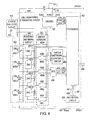
- FIG. 4 is a more detailed block diagram of an exemplary cell monitoring and balancing circuit consistent with the invention.
- FIG. 5 is an exemplary circuit diagram of one bleeding circuit that may be utilized in the bleeding network circuit of FIG. 4 .
- FIG. 1 a simplified block diagram of an electronic device 100 capable of being powered from a battery pack 102 or a DC power source 104 is illustrated.
- the battery pack 102 may containing a plurality of battery cells 102 - 1 , 102 - 2 , 102 - n .
- the cell types may be of various rechargeable types known in the art such as lithium-ion, nickel-cadmium, nickel-metal hydride batteries, or the like.
- the electronic device 100 is a laptop computer it would include a variety of components known to those skilled in the art which are not illustrated in FIG. 1 .
- the laptop may include an input device for inputting data to the laptop, a central processing unit (CPU) or processor, for example a Pentium processor available from Intel Corporation, for executing instructions and controlling operation of the laptop, and an output device, e.g., a LCD or speakers, for outputting data from the laptop.
- CPU central processing unit
- processor for example a Pentium processor available from Intel Corporation
- an output device e.g., a LCD or speakers
- a DC power source 104 may be coupled to the device 100 .
- the DC power source 104 may be an AC/DC adapter which is configured to receive conventional 120 volts AC from a wall outlet and convert it to a DC output voltage.
- the DC power source 104 may also be a DC/DC adapter such as a “cigarette lighter” type adapter configured to plug into that type of socket. Such a DC power source 104 is illustrated in FIG. 1 as separate from the device 100 , but it may be built into some devices.
- the electronic device 100 may also have a power supply block 110 .
- the power supply block 110 includes various components to monitor, control, and direct power from each power source 102 , 104 to each other and to the system 112 of the electronic device 100 under various conditions.
- the electronic device 100 includes a cell monitoring and balancing circuit 108 as further detailed herein.
- the cell monitoring and balancing circuit 108 is shown separate from the power supply block 110 for clarity, but it may be included as part of the power supply block 110 .
- the cell monitoring and balancing circuit 108 may function as a monitoring circuit, a balancing circuit, or both as further detailed herein.
- the cell monitoring and balancing circuit 108 provides digital signals representative of the voltage level of each cell 102 - 1 , 102 - 2 , 102 - n to various components of the device such as a battery gas gauge 118 .
- the battery gas gauge may utilize such signals to provide an output signal representative of the remaining useful life of the battery pack 102 .
- the monitoring circuit 208 generally includes an analog to digital converter (ADC) 220 and a processor 222 .
- the ADC 220 is configured to accept an analog voltage signal from each of the battery cells 102 - 1 , 102 - 2 , 102 - n and convert each to a digital signal.
- the processor 220 is configured to receive each digital signal and provide a safety alert signal based on at least one of the digital signals.
- the ADC 220 may function as an “averaging” type ADC to take an “average” reading of the voltage of each battery cell 102 - 1 , 1 - 2 - 2 , 102 - n such that transient deviations from normal readings will not adversely impact the quality of the digital signal representation of the analog signal.
- transient deviations could include voltage spikes or other rapid voltage fluctuations that can occur due to a number of factors including varying charging currents or load currents passing through the internal resistance of the cells.
- the ADC 220 may include one or more various types of ADCs to function as an averaging type ADC.
- the ADC 212 may include a single-slope integrating ADC, a dual-slope integrating type ADC, or a sigma-delta type ADC to name a few.
- Such a sigma-delta type ADC generally includes an analog modulator portion that essentially digitizes an input analog signal at very high sampling frequency equal to Fs ⁇ OSR, where Fs is the Nyquist Frequency and OSR is the over sampling ratio to the Nyquist Frequency. The outputs from this over sampling may be combined in groups and the groups may be averaged.
- An analog signal representing the voltage of any particular battery cell 102 - 1 , 102 - 2 , 102 - n may thus be sampled many times, e.g., in the thousands of times in some instances. As such, a few incorrect samplings of transient deviations will have little effect on the average signal converted by the averaging type ADC 220 to an associated digital signal.
- the ADC 220 may also have an adjustable resolution depending on a particular need.
- the processor 222 may instruct the ADC 220 via data path 217 to utilize a desired resolution level for a particular conversion of an analog signal from a particular battery cell 102 - 1 , 102 - 2 , 102 - n to an associated digital signal.
- the resolution may be adjusted to a relatively higher resolution in situations where there is more sensitivity to the analog voltage measurement. For example, such a situation requiring higher resolution may be for open circuit voltage detection.
- resolution may be adjusted to a relatively lower resolution in situations where there is less sensitivity to the analog voltage measurement. For example, such a situation requiring lower resolution may be for under-voltage detection.
- the lower the resolution the less time is needed to complete one valid analog to digital conversion.
- a relatively higher resolution may require 15 bits of data while the relatively lower resolution may only require 10 bits of data.
- the actual number of bits may vary depending on the particular requirements for the digital data and the resolution capabilities of the ADC 220 .
- the ADC 220 may be of any type of ADC that can adjust resolution upon direction from the ADC control signal from the processor 222 .
- the ADC 220 may be a sigma-delta type as earlier detailed.
- Such a sigma-delta modulator type can adjust resolution based, in part, on the OSR. In general, higher resolution can be obtained with a higher OSR.
- the ADC 220 may also be a successive approximation type ADC.
- a successive approximation type ADC conceptually uses a single comparator to make its conversion. If N bits of resolution are desired as indicated by the control signal from the processor 220 , a successive approximation type ADC would make N comparator operations to achieve N bits of resolution.
- Other types of ADCs such as a single-slope or dual-slope integrating type ADC, and or combinations of various types of ADCs may be used in an ADC 220 consistent with the invention to achieve an adjustable resolution.
- the processor 222 is configured to receive digital signals from the ADC 220 representative of the voltage level of each battery cell 102 - 1 , 102 - 2 , 102 - n and to provide a safety alert signal based on at least one of the digital signals.
- the safety alert signal may be a charge alert signal or a discharge alert signal.
- the processor 222 sends a charge alert signal if the digital signals from the ADC 220 indicate that at least one of the cells 102 - 1 , 102 - 2 , 102 - n has a voltage level greater than an over voltage threshold value over a predetermined time interval. As such, some preventative action may then be taken such as to stop charging. Alternatively, the processor 222 may also provide the charge alert signal if one of the digital signals from the ADC 220 indicates that one cell has a voltage level greater than the over voltage threshold level while the battery pack 102 is being charged.
- the monitoring circuit 208 may utilize a plurality of under voltage threshold levels to prevent damage to the cells and to provide adequate warnings to a user of an associated electronic device 100 .
- the processor 222 may send a discharge alert signal if the digital signals from the ADC 220 indicate that at least one of the cells 102 - 1 , 102 - 2 , 102 - n has a voltage level lower than an under voltage threshold value over a predetermined time interval while the battery pack 102 is being discharged. As such, some preventative action may then be taken such as to stop power supply from the battery pack.
- the processor 222 may also provide the discharge alert signal if one of the digital signals from the ADC 220 indicates that one cell has a voltage level less than the under voltage threshold level while the battery pack 102 is being discharged.
- under voltage threshold level In addition to the under voltage threshold level, other under voltage threshold voltage levels greater than the under voltage threshold level may also be utilized by the processor 222 to provide advanced notice of a potentially impending low voltage condition. For instance, if the electronic device 100 is a laptop computer and the under voltage threshold level is reached without any notice to the user, a user may lose a significant amount of important unsaved data.
- a first under voltage threshold level may be programmed into and stored in any applicable memory device of the system 100 .
- the processor 222 can compare such voltage levels to the first under voltage threshold level. If the voltage level on one of the cells drops below such level, the processor 222 can provide an appropriate signal via path 290 to other components of the system 100 . As such, an alert message may then be provided to a user of the electronic device 100 .
- the first under voltage threshold level may be chosen based on the system 100 particulars including the time required to perform typical tasks and the power required for such tasks.
- the first threshold level may be chosen high enough that upon notice of a low power condition (e.g., one cell of the cells 102 - 1 , 102 - 2 , 102 - n has a voltage level less than the first threshold level) a user still has enough power and time to operate the laptop for an additional time period.
- Another second threshold level which is less than the first threshold level, may also be utilized to indicate that a shorter time period is available to the user for proper operation. For instance, if the any cell voltage is less than the second threshold level, another alert signal may indicate to the user that there is likely only enough time for saving and shutting down of the laptop computer before the under voltage threshold level is reached and battery power to the system is halted.
- all threshold levels are adjustable by the processor 222 .
- the over and under voltage threshold level may be adjusted based on the particular type of cell utilized.
- the over and under voltage threshold values may be stored in any variety of electronic storage media in the device.
- the processor 222 may have internal registers 230 that could store such threshold levels.
- the over and under voltage threshold level can be adjusted based on other parameters that affect the charging and discharging performance of the cells such as ambient temperature and age of the cells.
- Ambient temperature information may be provided to the processor 222 by a temperature sensor 292 .
- a sampling time interval is also adjustable by the processor 222 .
- a sampling time interval includes that time period in which all cells are sampled once and a valid digital conversion is made by the ADC 220 for each cell. This enables the processor to sample the cells more frequently during certain conditions, e.g., during charging, when more frequent sampling is advantageous. This also enables the processor to sample the cells less frequently during other conditions, e.g., the battery pack 102 is in sleep or idle mode, when less frequent sampling is adequate. For example, such a sampling time interval may be once per minute when the battery pack is in sleep or idle mode. As such, the ADC 220 may also be placed in a sleep mode by the processor 222 in order to conserve energy when it is not needed to make a conversion.
- FIG. 3A a block diagram of an exemplary balancing circuit 308 is illustrated that may be utilized in the electronic device of FIG. 1 .
- the balancing circuit 308 generally includes an ADC 320 and processor 322 as previously detailed with respect to FIG. 2 .
- the processor 322 controls either the bleeding network circuit 340 , the charge shuttling circuit 342 , or both to balance voltage levels of the cells 102 - 1 , 102 - 2 , 102 - n as further detailed herein.
- the processor 322 receives associated digital signals from the ADC 320 as previously detailed that are representative of an accurate voltage reading for each cell 102 - 1 , 102 - 2 , 102 - n . As such, the processor 322 not only knows which cell has the highest voltage level and the lowest voltage level, it also knows the magnitude of the voltage difference between such cells and the voltage level of each cell. The processor 322 utilizes this information from the ADC 320 to make intelligent decisions regarding cell balancing as detailed herein that result in accurate and fast cell balancing.
- cell balancing decisions may be made at any time (during charging mode, discharging mode, or even during idle mode) whenever there is a voltage difference between the highest voltage cell and the lowest voltage cell that is greater than some battery cell balance threshold.
- cell balancing is useful to control the cells with the higher voltage levels to enable the lower voltage level cells time to catch up. Since battery charging is typically limited by any one cell reaching its end of charge voltage level, this enables each cell to approach its end of cell voltage level. Otherwise, a cell that reached its end of voltage level charge quickly would prevent other cells from being more fully charged.
- the processor 322 Since the processor 322 is repeatedly receiving updated accurate voltage information of each cell 102 - 1 , 10202 , 102 - n from the ADC 320 , it can instruct the bleeding network circuit 340 to conduct appropriate cell bleeding or it can instruct the charge shuttling circuit 342 to conduct appropriate charge transfers as soon as it detects a voltage difference between a higher voltage cell and a lower voltage cell is greater than a predetermined battery cell balance threshold.
- Balancing can occur by providing a bleeding current to one or more of the cells having higher voltage levels during certain time intervals. Such time intervals may overlap such that bleeding for more than one cell may occur at similar times.
- the starting times for the bleeding of two or more cells can start at substantially the same time in order to speed up the bleeding process.
- cell bleeding can be adjusted based on the difference in voltage between the higher and lower voltage cells. As such, a first cell with a relatively higher voltage level may be bled by a higher bleeding current than a second cell with a voltage level slightly less than the first cell.
- the upper limit of such bleeding current is typically limited by heat dissipation concerns.
- Balancing cell voltage levels can occur not only by bleeding the cells with the higher voltage levels, but also by shuttling charges from higher voltage cells to lower voltage cells.
- Such charge shuttling is controlled by the processor 322 which provides appropriate control signals to the switch network 350 to control the shuttling of charge from cells with higher voltage levels to cells with lower voltage levels by utilizing the charge shuttling circuit 342 .
- the processor 322 knows which one or more cells 102 - 1 , 102 - 2 , 102 - n have higher voltage readings compared to the others due to the digital signals received from the ADC 320 . As such, the processor 322 may direct the appropriate switches in the switch network 350 to close such that one or more cells with a higher voltage level transfers some charge level to the charge shuttling circuit 342 . The processor 322 may then further direct appropriate switches in the switch network 350 to close to transfer charges from the charge shuttling circuit 342 to the cell with a lower voltage level. Such a charge transfer process stops when the processor 322 instructs such process to stop, e.g., when the processor knows that an appropriate balanced voltage level is obtained between appropriate cells.
- the processor 322 may also provide a pre-balance signal to the bleeding network circuit 340 or the charge shuttling circuit 342 to start a balancing process before an imbalance exists.
- the pre-balance signal may be provided in a second mode if a cell imbalance occurred in a first mode occurring before the second mode.
- the first mode may be a first charging mode or a first discharging mode.
- the second mode may be a second charging mode or a second discharging mode.
- the processor 322 has each cell's voltage information in digital form and knows the cells voltage history.
- the processor 322 After one or more modes, e.g., charging and discharging cycles, if the processor 322 notices that an imbalance always happens to one specific cell, e.g., if one cell has a lower voltage level towards the end of discharge, then the processor can start a balancing process during a later mode before a noticeable voltage difference is even detectable.
- modes e.g., charging and discharging cycles
- FIG. 3B an exemplary plot of capacity (Ah) of a lithium ion cell at 21 degree Celsius versus cell voltage is illustrated for an exemplary Cell A 303 and Cell B 305 .
- Ah capacity of a lithium ion cell at 21 degree Celsius versus cell voltage
- the processor 322 knows that cell A typically has a lower voltage than cell B towards the end of discharge from at least one prior discharge cycle or mode, the processor 322 can start balancing for cell A early in a later discharge cycle or mode without waiting for the appreciable voltage difference to occur.
- the processor may instruct charges from Cell B and/or other cells to be transferred to the charge shuttling circuit 342 and then to Cell A early in the later discharge mode. In this way, Cell A may be balanced with Cell B so that no appreciable voltage difference exists between the cells near their end of discharge cycle.
- the cell monitoring and balancing circuit 408 includes the functionality of the monitoring circuit 208 of FIG. 2 and the balancing circuit 308 of FIG. 3 .
- the circuit 408 may include an ADC 420 , a processor 422 , a switch network control circuit 451 , a switch network 450 , a bleeding network circuit 440 , a driver circuit 427 , and a protection circuit 429 .
- Individual analog cell voltage levels for each cell of the battery pack 402 may be sampled directly through the switch network 450 .
- the sampled analog signals may then be converted into associated digital signals by the ADC 420 as previously detailed.
- the switches 450 a and 450 c of the switch network 450 close, while all other switches of the switch network 450 remain open.
- the positive terminal of the first cell 402 - 1 is coupled through switch 450 a to the positive input terminal of the ADC 420 .
- the negative terminal of the first cell 402 - 1 is coupled through switch 450 c to the negative input terminal of the ADC 420 . All switches of the switch network 450 will remain in these positions until a valid analog to digital conversion is completed by the ADC 420 over a given conversion time period for the first cell 402 - 1 .
- the second cell 402 - 2 (through closed switches 450 b and 450 e with other switches of the switch network 450 open), the third cell 402 - 3 (through closed switches 450 d and 450 g with other switches of the switch network 450 open), and the fourth cell 402 - 4 (through closed switches 450 f and 450 i with other switches of the switch network 450 open) may also be directly coupled to the ADC 420 in a like manner for direct sampling of each cell 402 - 2 , 402 - 3 , and 402 - 4 .
- the charge shuttling circuit 442 may include an energy storage element such as a transformer, inductor, or capacitor. In the illustrated embodiment, a capacitor 443 is utilized as the energy storage element. If charge shuttling among cells is directed by the processor 422 , the appropriate switches 450 a to 450 g of the switch network 450 direct charges from one or more of the cells with the higher voltage to be temporarily stored in the capacitor 443 . Such charges are then shuttled to a lower voltage cell by the appropriate switches of the switch network 450 . The processor 422 controls the switch network 450 via the switch network control circuit 451 .
- an energy storage element such as a transformer, inductor, or capacitor.
- a capacitor 443 is utilized as the energy storage element.
- An ADC 420 consistent with the invention may also be calibrated for each individual cell 402 - 1 , 402 - 2 , 402 - 3 , and 402 - 4 in order to compensate for any offset.
- Such offset can be due to any number of factors such as different voltage gradients, and switching charge injection for different ADC cell channels.
- switches 450 b and 450 c would be closed with all other switches of the switch network 450 open.
- the input terminals of the ADC 420 are connected to the virtual ground of the first cell 402 - 1 .
- the ADC 420 would then convert such analog signal into an associated first offset digital signal.
- the first offset digital signal may then be stored in any available memory device.
- switches 450 d and 450 e would be closed.
- switches 450 f and 450 g would be closed.
- switches 450 h and 450 i would be closed.
- four offset values for each associated cell 402 - 1 , 402 - 2 , 402 - 3 , and 402 - 4 can be obtained and stored.
- the processor 422 can instruct acquisition of offset-free data by subtracting the stored associated offset value for the associated cell. As such, accurate measurement of the analog signal from each cell is further promoted.
- a protection circuit 429 may also be incorporated into the cell balance and monitoring circuit 408 in order to monitor the current flowing into (charging mode) or out of (discharging mode) the battery pack 402 for various power crisis conditions, e.g., over current or short circuit conditions, and alert the processor 422 of such conditions so that preventative action can be taken.
- a current sensing element such as sense resistor 491 may be coupled to the battery pack 402 to provide the protection circuit 429 with a signal representative of the current level to or from the battery pack as that current level varies.
- the protection circuit 429 provides an over current alert signal to the processor 422 via data path 437 .
- the current level may be greater than a second current threshold level, where the second current threshold level is greater than the first current threshold level.
- the protection circuit 429 provides a short circuit alert signal to the processor via data path 439 .
- the processor 422 makes decisions and sends appropriate control signals such that appropriate power safety measures are taken.
- the processor 422 may provide an appropriate control signal to the switch driver 427 in order to drive the discharge switch Q 1 open.
- the processor 422 may also provide a message to a host component via data path 490 such that some alternative component, e.g., a power management unit, may manage any necessary corrective action to ensure power supply safety.
- the bleeding network circuit 440 may include a plurality of bleeding circuits 440 - 1 , 440 - 2 , 440 - 3 , and 440 - 4 to provide an adjustable bleeding current to each associated cell 402 - 1 , 402 - 2 , 402 - 3 , and 404 - 4 as previously detailed.
- the bleeding circuit 500 is responsive to a digital control signal from the processor 422 to control the bleeding current from the associated cell 402 - 1 , 402 - 2 , 402 - 3 , and 404 - 4 as previously detailed.
- the bleeding circuit 500 may include a plurality of switches S 0 , S 1 , S(N ⁇ 1) and an associated plurality of resistive elements, e.g., resistors, having varying resistive values R, R/2, and R/(N ⁇ 1).
- the switches may be MOSFET type transistors having their control or gate terminal configured to receive the digital control signal from the processor 422 .
- An N-bit digital control signal from the processor 422 may then dictate which switch S 0 , S 1 , S(N ⁇ 1) turns ON and hence which resistive value R, R/2, or R/(N ⁇ 1) is coupled in parallel with the associated battery cell 402 - 1 , 402 - 2 , 402 - 3 , and 404 - 4 , where the R/(N ⁇ 1) resistive value is less than the R/2 resistive value, and the R/2 resistive value is less than the R resistive value.
- the N-bit digital control signal from the processor 422 may instruct a second switch, e.g., switch S(N ⁇ 1), to close such that a lower resistive value, e.g., R/(N ⁇ 1), is coupled in parallel with the associated cell. As such, a larger bleeding current more quickly lowers the voltage level of the higher voltage cell.
- the N-bit control signal from the processor 422 may instruct a first switch, e.g., switch S 1 , to close such that a relatively higher resistive value, e.g., R, is coupled in parallel with the associated cell. As such, a relatively smaller bleeding current is provided to more slowly lower the voltage level of a higher voltage cell.
- the cell bleeding control signals from the processor 422 may also be provided to a battery gas gauge in order to provide such gauge with accurate cell bleeding information.
- a N-bit control signals provided to the cell bleeding circuits 440 - 1 , 440 - 2 , 440 - 3 , 440 - 4 may also be provided to associated battery gas gauge.
- the gauge also knows which cell 402 - 1 , 402 - 2 , 402 - 3 , 402 - 4 is being bled and the associated bleeding current level for each cell. Therefore, the gauge can make more reliable calculations to determine the remaining amount of battery life taking into account bleeding current levels for charging capacity calculations.
Abstract
Description
Claims (17)
Priority Applications (1)
| Application Number | Priority Date | Filing Date | Title |
|---|---|---|---|
| US13/214,611 US8836290B2 (en) | 2003-06-19 | 2011-08-22 | Battery cell monitoring and balancing circuit |
Applications Claiming Priority (4)
| Application Number | Priority Date | Filing Date | Title |
|---|---|---|---|
| US10/464,973 US7081737B2 (en) | 2003-06-19 | 2003-06-19 | Battery cell monitoring and balancing circuit |
| US11/459,473 US7696725B2 (en) | 2003-06-19 | 2006-07-24 | Battery cell monitoring and balancing circuit |
| US12/759,623 US8004246B2 (en) | 2003-06-19 | 2010-04-13 | Battery cell monitoring and balancing circuit |
| US13/214,611 US8836290B2 (en) | 2003-06-19 | 2011-08-22 | Battery cell monitoring and balancing circuit |
Related Parent Applications (1)
| Application Number | Title | Priority Date | Filing Date |
|---|---|---|---|
| US12/759,623 Division US8004246B2 (en) | 2003-06-19 | 2010-04-13 | Battery cell monitoring and balancing circuit |
Publications (2)
| Publication Number | Publication Date |
|---|---|
| US20110298425A1 US20110298425A1 (en) | 2011-12-08 |
| US8836290B2 true US8836290B2 (en) | 2014-09-16 |
Family
ID=33517400
Family Applications (5)
| Application Number | Title | Priority Date | Filing Date |
|---|---|---|---|
| US10/464,973 Expired - Lifetime US7081737B2 (en) | 2003-06-19 | 2003-06-19 | Battery cell monitoring and balancing circuit |
| US11/459,473 Expired - Lifetime US7696725B2 (en) | 2003-06-19 | 2006-07-24 | Battery cell monitoring and balancing circuit |
| US12/759,623 Expired - Lifetime US8004246B2 (en) | 2003-06-19 | 2010-04-13 | Battery cell monitoring and balancing circuit |
| US12/759,614 Expired - Lifetime US8237411B2 (en) | 2003-06-19 | 2010-04-13 | Battery cell monitoring and balancing circuit |
| US13/214,611 Expired - Lifetime US8836290B2 (en) | 2003-06-19 | 2011-08-22 | Battery cell monitoring and balancing circuit |
Family Applications Before (4)
| Application Number | Title | Priority Date | Filing Date |
|---|---|---|---|
| US10/464,973 Expired - Lifetime US7081737B2 (en) | 2003-06-19 | 2003-06-19 | Battery cell monitoring and balancing circuit |
| US11/459,473 Expired - Lifetime US7696725B2 (en) | 2003-06-19 | 2006-07-24 | Battery cell monitoring and balancing circuit |
| US12/759,623 Expired - Lifetime US8004246B2 (en) | 2003-06-19 | 2010-04-13 | Battery cell monitoring and balancing circuit |
| US12/759,614 Expired - Lifetime US8237411B2 (en) | 2003-06-19 | 2010-04-13 | Battery cell monitoring and balancing circuit |
Country Status (5)
| Country | Link |
|---|---|
| US (5) | US7081737B2 (en) |
| JP (1) | JP3893137B2 (en) |
| KR (1) | KR100616163B1 (en) |
| CN (4) | CN2711747Y (en) |
| TW (2) | TWI237917B (en) |
Cited By (6)
| Publication number | Priority date | Publication date | Assignee | Title |
|---|---|---|---|---|
| US20180205239A1 (en) * | 2017-01-17 | 2018-07-19 | Taiyo Yuden Co., Ltd. | Power supply module with lithium ion capacitor |
| US20190187213A1 (en) * | 2017-12-20 | 2019-06-20 | National Chung Shan Institute Of Science And Technology | Battery balance management circuit |
| US10587128B2 (en) * | 2015-06-30 | 2020-03-10 | SZ DJI Technology Co., Ltd. | Charging control circuit, charging device, charging system and charging control method |
| US20210184473A1 (en) * | 2019-12-11 | 2021-06-17 | Nanjing Chervon Industry Co., Ltd. | Battery pack and charging balancing method for the same |
| US11239670B2 (en) * | 2018-09-16 | 2022-02-01 | Richard Landry Gray | Cell balancing battery module and electrical apparatus |
| US11251628B2 (en) * | 2017-01-23 | 2022-02-15 | Rafael Advanced Defense Systems Ltd. | System for balancing a series of cells |
Families Citing this family (211)
| Publication number | Priority date | Publication date | Assignee | Title |
|---|---|---|---|---|
| US7081737B2 (en) * | 2003-06-19 | 2006-07-25 | O2Micro International Limited | Battery cell monitoring and balancing circuit |
| US20070257642A1 (en) * | 2003-06-19 | 2007-11-08 | Sean Xiao | Battery cell monitoring and balancing circuit |
| FR2880995B1 (en) * | 2005-01-14 | 2007-04-06 | Pellenc Sa | METHOD FOR BALANCED LOADING OF LITHIUM-ION OR POLYMER LITHIUM BATTERY |
| KR100686794B1 (en) * | 2005-01-25 | 2007-02-23 | 삼성에스디아이 주식회사 | Battery monitoring system and its method |
| AU2006232083B2 (en) * | 2005-04-05 | 2010-02-11 | Energycs | Multiplexer and switch-based electrochemical cell monitor and management system and method |
| KR100669434B1 (en) * | 2005-04-07 | 2007-01-15 | 삼성에스디아이 주식회사 | Method for controlling secondary battery module |
| KR100831160B1 (en) * | 2005-04-15 | 2008-05-20 | 주식회사 엘지화학 | Switching circuit for balancing of battery cell |
| KR100717789B1 (en) | 2005-07-29 | 2007-05-11 | 삼성에스디아이 주식회사 | Method for estimating soc of secondary battery module |
| KR100739054B1 (en) | 2005-10-20 | 2007-07-12 | 삼성에스디아이 주식회사 | Battery management system and method for measuring cell voltage of the battery |
| KR100740097B1 (en) | 2005-10-20 | 2007-07-16 | 삼성에스디아이 주식회사 | Method of estimating SOC for battery and battery management system using the same |
| JP4241714B2 (en) * | 2005-11-17 | 2009-03-18 | パナソニック電工株式会社 | Battery pack for power tools |
| JP4241715B2 (en) * | 2005-11-17 | 2009-03-18 | パナソニック電工株式会社 | Battery pack for power tools |
| US7782017B2 (en) * | 2006-02-28 | 2010-08-24 | Linear Technology Corporation | Apparatus and method for producing signal conveying circuit status information |
| CN100372213C (en) * | 2006-03-15 | 2008-02-27 | 李慧琪 | Evenly charging method and charger for serial batteries |
| KR100727002B1 (en) * | 2006-03-28 | 2007-06-14 | 넥스콘 테크놀러지 주식회사 | A li-ion or li-polymer batterie balancing module for a hybrid electric vehicle |
| KR100818519B1 (en) * | 2006-05-04 | 2008-03-31 | 주식회사 엘지화학 | Method and apparatus of controlling battery |
| KR100905663B1 (en) * | 2006-07-13 | 2009-06-30 | 주식회사 엘지화학 | Circuit current balancing method and apparatus for battery apparatus |
| KR100796668B1 (en) | 2006-09-26 | 2008-01-22 | 삼성에스디아이 주식회사 | Battery management system and driving method thereof |
| KR100859688B1 (en) | 2006-10-12 | 2008-09-23 | 삼성에스디아이 주식회사 | Battery management system and driving method thereof |
| KR100814884B1 (en) | 2006-10-16 | 2008-03-20 | 삼성에스디아이 주식회사 | Battery management system and driving method thereof |
| KR100839381B1 (en) | 2006-11-01 | 2008-06-20 | 삼성에스디아이 주식회사 | Battery management system and driving method thereof |
| US7598706B2 (en) * | 2007-01-26 | 2009-10-06 | General Electric Company | Cell balancing battery pack and method of balancing the cells of a battery |
| US7372392B1 (en) * | 2007-02-26 | 2008-05-13 | National Semiconductor Corporation | Charge balancing method in a current input ADC |
| DE102007010988B3 (en) * | 2007-03-05 | 2008-10-16 | Varta Automotive Systems Gmbh | Method and device for determining a compensation charge of a rechargeable battery |
| US8222870B2 (en) * | 2007-03-07 | 2012-07-17 | O2Micro, Inc | Battery management systems with adjustable charging current |
| US7973515B2 (en) * | 2007-03-07 | 2011-07-05 | O2Micro, Inc | Power management systems with controllable adapter output |
| US20080218127A1 (en) * | 2007-03-07 | 2008-09-11 | O2Micro Inc. | Battery management systems with controllable adapter output |
| KR100882913B1 (en) | 2007-03-19 | 2009-02-10 | 삼성에스디아이 주식회사 | Battery Pack |
| JP4388094B2 (en) * | 2007-03-28 | 2009-12-24 | 株式会社東芝 | Battery pack protection device and battery pack device |
| FR2915328A1 (en) * | 2007-04-18 | 2008-10-24 | Valeo Equip Electr Moteur | Energy storage device for motor vehicle, has balancing circuit for drawing energy from energy storage cell and distributing drawn energy towards another energy storage cell, where cells are connected in series and formed by super-capacitors |
| DE102007031568A1 (en) * | 2007-07-06 | 2009-01-08 | Robert Bosch Gmbh | Device, in particular charger device, for charging a rechargeable battery |
| US8274261B2 (en) * | 2007-07-13 | 2012-09-25 | Black & Decker Inc. | Cell monitoring and balancing |
| US7683575B2 (en) * | 2007-07-18 | 2010-03-23 | Tesla Motors, Inc. | Method and apparatus for identifying and disconnecting short-circuited battery cells within a battery pack |
| JP2009055755A (en) * | 2007-08-29 | 2009-03-12 | Ricoh Co Ltd | Semiconductor device for protecting secondary battery |
| US8461806B2 (en) * | 2007-10-15 | 2013-06-11 | O2Micro Inc | Systems and methods for cell balancing |
| US20090079391A1 (en) * | 2007-09-25 | 2009-03-26 | O2Micro Inc. | Systems and methods for cell balancing |
| TW200917622A (en) * | 2007-10-12 | 2009-04-16 | Acer Inc | Battery charging method and device thereof |
| KR100998302B1 (en) | 2007-12-07 | 2010-12-06 | 삼성에스디아이 주식회사 | Method for charging of secondary battery and charging device |
| US8030895B2 (en) * | 2007-12-27 | 2011-10-04 | Fenghua Xiao | Cell balancing systems with multiple controllers |
| JP5469813B2 (en) * | 2008-01-29 | 2014-04-16 | 株式会社日立製作所 | Battery system for vehicles |
| JP2009247195A (en) * | 2008-03-31 | 2009-10-22 | O2 Micro Inc | Battery management system with adjustable charging current |
| WO2009124191A2 (en) * | 2008-04-02 | 2009-10-08 | Infinite Power Solutions, Inc. | Passive over/under voltage control and protection for energy storage devices associated with energy harvesting |
| KR101016899B1 (en) * | 2008-06-03 | 2011-02-22 | 삼성에스디아이 주식회사 | Battery pack and method of charge thereof |
| US8111038B2 (en) * | 2008-06-12 | 2012-02-07 | O2 Micro, Inc | Vehicle electronic systems with battery management functions |
| US20110103628A1 (en) * | 2008-06-18 | 2011-05-05 | Phonak Ag | Hearing device and method for operating the same |
| DE102008032263A1 (en) * | 2008-07-09 | 2010-01-21 | Li-Tec Battery Gmbh | According to galvanic principles working electrical device |
| GB2462467B (en) * | 2008-08-08 | 2013-03-13 | P G Drives Technology Ltd | A cell management system |
| KR100993655B1 (en) | 2008-08-12 | 2010-11-10 | 기아자동차주식회사 | Method of balancing cell in battery pack of hev |
| JP5529402B2 (en) * | 2008-08-13 | 2014-06-25 | 三菱重工業株式会社 | Power storage system |
| US8093862B2 (en) * | 2008-09-03 | 2012-01-10 | Modalis Engineering, Inc. | Systems, apparatus and methods for battery charge management |
| DE102008053011A1 (en) | 2008-10-23 | 2010-04-29 | Li-Tec Battery Gmbh | Galvanic cell for a rechargeable battery |
| DE102008053009A1 (en) * | 2008-10-23 | 2010-04-29 | Li-Tec Battery Gmbh | Electrodes for a galvanic-based electrical device, such as lithium-ion cells, and methods of making same |
| DE102008052985A1 (en) * | 2008-10-23 | 2010-04-29 | Li-Tec Battery Gmbh | Packaging device and packaging system for substantially flat objects, for example lithium-ion cells |
| DE102008053089A1 (en) * | 2008-10-24 | 2010-04-29 | Li-Tec Battery Gmbh | Accumulator with several galvanic cells |
| JP2010104179A (en) * | 2008-10-24 | 2010-05-06 | Sanyo Electric Co Ltd | Power supply device and electric vehicle |
| WO2010058460A1 (en) * | 2008-11-19 | 2010-05-27 | 東芝三菱電機産業システム株式会社 | Secondary battery system |
| TWI376081B (en) * | 2008-12-08 | 2012-11-01 | Green Solution Tech Co Ltd | The battery charging controller and battery balance charging controller |
| DE102008062158A1 (en) * | 2008-12-15 | 2010-06-17 | Li-Tec Battery Gmbh | Device for storing electrical energy |
| AT507703B1 (en) * | 2008-12-22 | 2012-06-15 | Moove Gmbh E | ENERGY STORAGE ARRANGEMENT AND METHOD FOR OPERATING SUCH AN ARRANGEMENT |
| CN101789609B (en) * | 2009-01-23 | 2012-12-12 | 凹凸电子(武汉)有限公司 | Battery equalization system, method and circuit |
| US8232768B2 (en) * | 2009-01-23 | 2012-07-31 | O2Micro, Inc. | System and method for balancing battery cells |
| US8350528B2 (en) | 2009-02-04 | 2013-01-08 | Samsung Sdi Co., Ltd. | Battery pack and balancing method of battery cells |
| US8183870B1 (en) | 2009-02-12 | 2012-05-22 | The United States Of America As Represented By The Administrator Of The National Aeronautics And Space Administration | Battery system and method for sensing and balancing the charge state of battery cells |
| US8896315B1 (en) | 2009-02-12 | 2014-11-25 | The United States Of America As Represented By The Administrator Of The National Aeronautics And Space Administration | Battery cell balancing system and method |
| US9001071B2 (en) | 2009-02-23 | 2015-04-07 | Novatek Microelectronics Corp. | Energy-efficient touch panel device and related method |
| TWI397807B (en) * | 2009-02-23 | 2013-06-01 | Novatek Microelectronics Corp | Energy-efficient touch panel device and related method |
| KR101081207B1 (en) | 2009-03-03 | 2011-11-07 | 현대자동차주식회사 | Voltage Sensing Instrument for HEV Energy storage System |
| WO2010102287A2 (en) * | 2009-03-06 | 2010-09-10 | Asic Advantage, Inc. | Battery charge and discharge controller |
| US8519670B2 (en) * | 2009-03-23 | 2013-08-27 | Motiv Power Systems, Inc. | System and method for balancing charge within a battery pack |
| KR101043445B1 (en) * | 2009-03-23 | 2011-06-22 | 에스케이이노베이션 주식회사 | Insulation resistance measurement circuit using resistance connected with battery |
| US8493028B2 (en) * | 2009-04-03 | 2013-07-23 | Marvell World Trade Ltd. | Power management circuit for rechargeable battery stack |
| US8884585B2 (en) | 2009-04-16 | 2014-11-11 | Valence Technology, Inc. | Batteries, battery systems, battery submodules, battery operational methods, battery system operational methods, battery charging methods, and battery system charging methods |
| US8598845B2 (en) * | 2009-04-20 | 2013-12-03 | Valence Technology, Inc. | Battery chargers, electrical systems, and rechargeable battery charging methods |
| JP2011010448A (en) * | 2009-06-25 | 2011-01-13 | Yazaki Corp | Control unit |
| US20110169450A1 (en) * | 2009-07-14 | 2011-07-14 | Hudnall Coy A | Battery control apparatus |
| JP5328574B2 (en) * | 2009-09-04 | 2013-10-30 | 矢崎総業株式会社 | Voltage measurement device for multiple assembled batteries |
| CN101692507B (en) * | 2009-09-25 | 2012-08-22 | 北京北方专用车新技术发展有限公司 | Active equalization method for lithium ion battery pack in state of low current discharge |
| US8698351B2 (en) * | 2009-10-20 | 2014-04-15 | Motiv Power Systems, Inc. | System and method for managing a power system with multiple power components |
| EP2514064B1 (en) * | 2009-12-14 | 2020-04-08 | Leach International Corporation | Systems and methods for balancing multi-cell batteries |
| US9291680B2 (en) | 2009-12-29 | 2016-03-22 | O2Micro Inc. | Circuits and methods for measuring a cell voltage in a battery |
| US20130041606A1 (en) * | 2011-08-10 | 2013-02-14 | XiaoHu Tang | Detecting an open wire between a battery cell and an external circuit |
| US8629679B2 (en) * | 2009-12-29 | 2014-01-14 | O2Micro, Inc. | Circuits and methods for measuring cell voltages in battery packs |
| TWI405996B (en) * | 2009-12-29 | 2013-08-21 | Lite On Electronics Guangzhou | Cell pack balancing method |
| US8030973B2 (en) * | 2009-12-29 | 2011-10-04 | O2Micro Inc. | Calculating a parameter indicative of an error factor of a circuit |
| US8525478B2 (en) | 2010-01-06 | 2013-09-03 | Marvell World Trade Ltd. | Power management circuit of rechargeable battery stack |
| JP4954335B2 (en) * | 2010-01-08 | 2012-06-13 | Jfeエンジニアリング株式会社 | Quick charger |
| CN101764395B (en) * | 2010-01-14 | 2012-05-30 | 深圳市宏电技术股份有限公司 | Low-voltage protection method for lead-acid battery and power management system |
| TWI419433B (en) * | 2010-01-28 | 2013-12-11 | Joy Ride Tech Co Ltd | Series battery system with automatic bypass function |
| TWI419434B (en) * | 2010-02-01 | 2013-12-11 | Joy Ride Tech Co Ltd | Battery charge balance system |
| US9157967B2 (en) * | 2010-02-11 | 2015-10-13 | A123 Systems Llc | System and method for assessing voltage threshold detecting circuitry within a battery pack |
| US8872478B2 (en) * | 2010-03-09 | 2014-10-28 | O2Micro Inc. | Circuit and method for balancing battery cells |
| DE102010011277B4 (en) | 2010-03-13 | 2018-09-20 | Continental Automotive Gmbh | Battery system and method for changing the state of charge of a battery system |
| JP5601568B2 (en) * | 2010-03-19 | 2014-10-08 | いすゞ自動車株式会社 | Voltage regulation system |
| JP5554622B2 (en) * | 2010-04-21 | 2014-07-23 | 株式会社マキタ | Electric tool equipment |
| DE102010030491A1 (en) * | 2010-06-24 | 2011-12-29 | Sb Limotive Company Ltd. | Method for determining at least one state of a plurality of battery cells, computer program, battery and motor vehicle |
| CN102299529B (en) * | 2010-06-25 | 2014-04-02 | 凹凸电子(武汉)有限公司 | Battery pack management system, electric vehicle and battery pack management method |
| US8723481B2 (en) | 2010-06-25 | 2014-05-13 | O2Micro, Inc. | Battery pack with balancing management |
| US8219333B2 (en) * | 2010-06-29 | 2012-07-10 | O2Micro, Inc | Battery management systems for protecting batteries from fault conditions |
| JP5618359B2 (en) | 2010-08-02 | 2014-11-05 | Necエナジーデバイス株式会社 | Secondary battery pack connection control method and power storage system |
| KR101174893B1 (en) * | 2010-08-06 | 2012-08-17 | 삼성에스디아이 주식회사 | A battery pack and method for controlling the battery pack |
| KR20120016937A (en) * | 2010-08-17 | 2012-02-27 | 삼성전기주식회사 | Apparatus for equalizing voltage using time switch |
| CN102377203B (en) * | 2010-08-26 | 2015-11-25 | 联想(北京)有限公司 | A kind of electronic equipment and charge control method thereof |
| US8742722B2 (en) * | 2010-08-27 | 2014-06-03 | International Rectifier Corporation | Dynamic power management system and method |
| KR101750055B1 (en) | 2010-09-13 | 2017-06-22 | 삼성전자주식회사 | Auxiliary power device, memory system havtng its, and cell balancing method thereof |
| WO2012056417A2 (en) | 2010-10-29 | 2012-05-03 | Sendyne Corp. | Charge redistribution method for cell arrays |
| US8378868B2 (en) * | 2010-11-04 | 2013-02-19 | Texas Instruments Incorporated | Systems and methods for analog to digital converter charge storage device measurement |
| US9851412B2 (en) | 2010-11-09 | 2017-12-26 | International Business Machines Corporation | Analyzing and controlling performance in a composite battery module |
| JP5786324B2 (en) * | 2010-11-17 | 2015-09-30 | 日産自動車株式会社 | Battery control device |
| US8593110B2 (en) | 2010-11-19 | 2013-11-26 | General Electric Company | Device and method of battery discharge |
| US8395519B2 (en) | 2010-11-19 | 2013-03-12 | General Electric Company | Device and method of determining safety in a battery pack |
| KR101146404B1 (en) | 2010-12-20 | 2012-05-17 | 삼성에스디아이 주식회사 | Battery management system and battery pack comprising the same |
| KR101256079B1 (en) | 2010-12-28 | 2013-04-19 | 삼성에스디아이 주식회사 | Balancing Method and Balancing System of Battery Pack |
| US8773068B2 (en) | 2011-01-20 | 2014-07-08 | Valence Technology, Inc. | Rechargeable battery systems and rechargeable battery system operational methods |
| US8957624B2 (en) | 2011-01-20 | 2015-02-17 | Valence Technology, Inc. | Rechargeable battery systems and rechargeable battery system operational methods |
| US8922167B2 (en) | 2011-01-20 | 2014-12-30 | Valence Technology, Inc. | Rechargeable battery systems and rechargeable battery system operational methods |
| CN102111003B (en) * | 2011-02-21 | 2013-07-17 | 成都芯源系统有限公司 | Novel battery equalization circuit and adjusting method thereof |
| JP5603807B2 (en) * | 2011-03-07 | 2014-10-08 | Ntn株式会社 | Electric vehicle drive motor diagnosis device and diagnosis method, and electric vehicle drive motor diagnosis device |
| DE102011005411A1 (en) * | 2011-03-11 | 2012-09-13 | Robert Bosch Gmbh | Energy storage and charging process |
| TW201237758A (en) * | 2011-03-15 | 2012-09-16 | Askey Computer Corp | Lithium cell simulating device |
| CN102457078A (en) * | 2011-03-30 | 2012-05-16 | 凹凸电子(武汉)有限公司 | Cell equalization circuit, cell equalization system and method thereof |
| CN102148522B (en) * | 2011-05-04 | 2013-05-01 | 柳州五菱汽车有限责任公司 | Storage battery pack control method and system |
| US9575135B2 (en) * | 2011-06-01 | 2017-02-21 | Datang Nxp Semiconductors Co., Ltd. | Battery monitoring circuit, apparatus and method |
| JP2012253951A (en) * | 2011-06-03 | 2012-12-20 | Sony Corp | Power supply apparatus, charging method, rechargeable battery module, and charging apparatus |
| FR2976738B1 (en) * | 2011-06-14 | 2013-07-19 | Commissariat Energie Atomique | BATTERY SYSTEM OF BATTERIES WITH SIMPLIFIED SUPERVISION |
| US8692509B2 (en) | 2011-06-23 | 2014-04-08 | Black & Decker Inc. | Charge control scheme for use in power tools |
| JP5505375B2 (en) * | 2011-06-29 | 2014-05-28 | 株式会社豊田自動織機 | Cell balance control device and cell balance control method |
| US9048670B2 (en) * | 2011-07-12 | 2015-06-02 | National Semiconductor Corporation | System and method for balancing electrical energy storage devices via differential power bus and capacitive load switched-mode power supply |
| CN102916458B (en) | 2011-08-05 | 2015-06-17 | 凹凸电子(武汉)有限公司 | Battery equalizing system, circuit and method |
| JP6046380B2 (en) * | 2011-08-31 | 2016-12-14 | サターン ライセンシング エルエルシーSaturn Licensing LLC | Switch, charge monitoring device, and rechargeable battery module |
| TWI450083B (en) * | 2011-09-09 | 2014-08-21 | Ghing Hsin Dien | Power management apparatus |
| TWI435513B (en) * | 2011-09-29 | 2014-04-21 | 華晶科技股份有限公司 | Charger calibrating device and calibrating method thereof |
| WO2013052692A2 (en) | 2011-10-04 | 2013-04-11 | Advanergy, Inc. | Data server system and method |
| US8649883B2 (en) | 2011-10-04 | 2014-02-11 | Advanergy, Inc. | Power distribution system and method |
| US8553055B1 (en) | 2011-10-28 | 2013-10-08 | Graphic Products, Inc. | Thermal printer operable to selectively control the delivery of energy to a print head of the printer and method |
| US8477162B1 (en) | 2011-10-28 | 2013-07-02 | Graphic Products, Inc. | Thermal printer with static electricity discharger |
| US8482586B1 (en) | 2011-12-19 | 2013-07-09 | Graphic Products, Inc. | Thermal printer operable to selectively print sub-blocks of print data and method |
| CN102437613A (en) * | 2011-12-16 | 2012-05-02 | 奇瑞汽车股份有限公司 | Equalization system of lithium ion battery and equalization method thereof |
| TWI470858B (en) * | 2011-12-20 | 2015-01-21 | Nat Inst Chung Shan Science & Technology | Mechanical Starting Device for Impact Battery and Its Starting Method |
| TW201328115A (en) * | 2011-12-30 | 2013-07-01 | Hon Hai Prec Ind Co Ltd | Power device |
| CN102570551A (en) * | 2012-01-16 | 2012-07-11 | 安徽力高新能源技术有限公司 | Battery pack equalizing device with radiating function |
| CN104106175A (en) * | 2012-02-28 | 2014-10-15 | 智晖有限公司 | Method for charge balancing and load control in parallel battery packs |
| CN102655346B (en) * | 2012-04-25 | 2016-04-20 | 浙江大学 | There is Smart battery module and the battery pack of autobalance ability |
| CN103633671A (en) * | 2012-08-21 | 2014-03-12 | 宏碁股份有限公司 | Charging device for charging multiple batteries and bidirectional charging method |
| CN102882261B (en) * | 2012-10-29 | 2014-11-19 | 成都芯源系统有限公司 | Charging system, digital interface circuit and control method thereof |
| KR102052590B1 (en) * | 2012-11-22 | 2019-12-05 | 삼성에스디아이 주식회사 | Battery management system and driving method thereof |
| CN103078378A (en) * | 2013-01-17 | 2013-05-01 | 安徽日竞控制技术有限公司 | Automatic directional nondestructive equilibrium method of multiple series of lithium batteries and system thereof |
| US20140253040A1 (en) * | 2013-03-07 | 2014-09-11 | Apple Inc. | Preventive balancing technique for battery packs in portable electronic devices |
| US9496740B2 (en) * | 2013-06-16 | 2016-11-15 | Chris Beckman | Techniques for optimizing power supply output |
| KR102201102B1 (en) | 2013-03-15 | 2021-01-12 | 디자인 플럭스 테크놀로지스, 엘엘씨 | Method and apparatus for creating a dynamically reconfigurable energy storage device |
| US9397690B2 (en) | 2013-03-21 | 2016-07-19 | Freescale Semiconductor, Inc. | Apparatus and method for monitoring electrical current |
| US9365120B2 (en) * | 2013-03-29 | 2016-06-14 | Fca Us Llc | Techniques for enhanced battery pack recharging |
| CN103178586A (en) * | 2013-04-15 | 2013-06-26 | 北京空间飞行器总体设计部 | Equalizing charge manager of lithium ion battery pack for spacecraft |
| CN104166096A (en) * | 2013-05-16 | 2014-11-26 | 鸿富锦精密工业(深圳)有限公司 | Electric quantity prompting apparatus and electric quantity prompting method thereof |
| US9322885B2 (en) * | 2013-11-26 | 2016-04-26 | Infineon Technologies Ag | Circuit and method for evaluating cells in a battery |
| KR101527136B1 (en) * | 2013-12-19 | 2015-06-09 | 현대오트론 주식회사 | Apparatus for diagnosing battery of electric vehicle and method thereof |
| CN103682486A (en) * | 2013-12-23 | 2014-03-26 | 中国科学院电工研究所 | Multi-module cascading balancing method for cells |
| US10481211B2 (en) | 2014-01-15 | 2019-11-19 | Lat Enterprises, Inc. | State-of-charge indicator |
| CN103779938B (en) * | 2014-02-11 | 2016-01-20 | 湖南江麓容大车辆传动股份有限公司 | Battery pack charging balanced circuit, method and discharge equalizing circuit, method |
| TWI519024B (en) * | 2014-04-11 | 2016-01-21 | 虹光精密工業股份有限公司 | Multi-stage discharge circuit for an electronic device and a multi-stage discharge method |
| US9404977B2 (en) * | 2014-04-17 | 2016-08-02 | Ford Global Technologies, Llc | Bidirectional DC converter-based battery simulator |
| CN104348219B (en) * | 2014-07-15 | 2017-02-08 | 常州格力博有限公司 | Electrical system with replaceable batteries |
| WO2016053385A1 (en) * | 2014-10-03 | 2016-04-07 | Elitise Llc | Battery module architecture with horizontal and vertical expandability |
| DE102015217692A1 (en) * | 2014-10-09 | 2016-04-14 | Ford Global Technologies, Llc | Method for monitoring the condition of a battery in a motor vehicle |
| US9853471B2 (en) * | 2014-12-16 | 2017-12-26 | Intel Corporation | Mechanism for extending cycle life of a battery |
| KR101619268B1 (en) * | 2015-03-20 | 2016-05-10 | 포항공과대학교 산학협력단 | Balancing method of battery cell |
| US10666069B2 (en) * | 2015-04-10 | 2020-05-26 | Semiconductor Components Industries, Llc | Inhibiting excessive battery discharge using battery voltage and capacity measurements |
| TWI562492B (en) * | 2015-05-06 | 2016-12-11 | Go Tech Energy Co Ltd | Compulsory charging and protective circuit for secondary battery after being over discharged |
| CN105048602B (en) | 2015-08-31 | 2017-12-05 | 矽力杰半导体技术(杭州)有限公司 | Cell balancing circuit and cell apparatus |
| CN105186623B (en) * | 2015-09-30 | 2018-02-16 | 矽力杰半导体技术(杭州)有限公司 | Cell equalization device |
| CN105182248B (en) * | 2015-10-10 | 2017-11-10 | 穆良柱 | Secondary cell detecting system and prediction type control method |
| CN105161783B (en) | 2015-10-14 | 2017-12-19 | 矽力杰半导体技术(杭州)有限公司 | Cell equalization method |
| CN105629046B (en) * | 2015-12-18 | 2019-02-15 | 无锡中感微电子股份有限公司 | Multiple batteries observation circuit and its system |
| JP6627567B2 (en) * | 2016-02-25 | 2020-01-08 | 富士通株式会社 | Power supply device, storage device, and power supply control method |
| EP3424123B1 (en) * | 2016-03-01 | 2022-08-03 | Volvo Truck Corporation | A method and system for controlling a current being fed to a battery pack |
| CN105896663B (en) * | 2016-05-13 | 2018-06-12 | 北京空间飞行器总体设计部 | A kind of sampling flow equalizing circuit of battery balanced manager |
| US10283978B2 (en) * | 2016-06-27 | 2019-05-07 | Lg Chem, Ltd. | Diagnostic system for a battery system |
| US10903665B2 (en) | 2016-11-01 | 2021-01-26 | Microsoft Technology Licensing, Llc | Usage data based battery charge or discharge time determination |
| CN106569536B (en) * | 2016-11-10 | 2018-09-07 | 惠州Tcl移动通信有限公司 | A kind of Automatic adjustment method and its device based on cell voltage control |
| US11656666B2 (en) | 2016-11-16 | 2023-05-23 | Microsoft Technology Licensing, Llc | Dynamic power source selection, charging, and discharging |
| US10488905B2 (en) | 2016-11-16 | 2019-11-26 | Microsoft Technology Licensing, Llc | Dynamic energy storage device discharging |
| US10063070B2 (en) * | 2016-11-25 | 2018-08-28 | National Chung Shan Institute Of Science And Technology | Battery active balancing system |
| US10377262B2 (en) * | 2016-12-06 | 2019-08-13 | National Chung Shan Institute Of Science And Technology | Range extending apparatus for electric vehicle and control method thereof |
| US10574076B2 (en) * | 2016-12-20 | 2020-02-25 | Maxwell Technologies, Inc. | Systems and methods for improving cell balancing and cell failure detection |
| CN106786879B (en) * | 2016-12-21 | 2023-07-18 | 杰华特微电子股份有限公司 | Battery pack charging control method and charging assembly |
| JP6658610B2 (en) * | 2017-02-27 | 2020-03-04 | カシオ計算機株式会社 | Information notification method, information notification device, and program |
| US10725529B2 (en) | 2017-06-26 | 2020-07-28 | Microsoft Technology Licensing, Llc | Target based power management |
| US20200287394A1 (en) * | 2017-09-22 | 2020-09-10 | Urban Electric Power Inc. | A system to charge cells assembled into a battery |
| US10938074B2 (en) * | 2017-10-17 | 2021-03-02 | Getac Technology Corporation | Electronic device, discharging method for the same, and charging method for the same |
| KR102530221B1 (en) | 2017-11-28 | 2023-05-09 | 삼성전자주식회사 | Method and apparatus for managing battery |
| TWI667864B (en) * | 2017-12-26 | 2019-08-01 | 國家中山科學研究院 | Battery balance management circuit |
| TWI662765B (en) * | 2018-04-13 | 2019-06-11 | 神基科技股份有限公司 | Charging device and method thereof |
| CN110682831B (en) * | 2018-06-19 | 2021-05-14 | 广州汽车集团股份有限公司 | Vehicle-mounted power battery equalization method and device and automobile |
| EP3671683B1 (en) * | 2018-09-28 | 2023-03-08 | Patlite Corporation | Notification system |
| US11209883B2 (en) * | 2018-11-01 | 2021-12-28 | Elo Touch Solutions, Inc. | Snap on power over the ethernet (POE) monitor system |
| CN109683098B (en) * | 2018-12-19 | 2021-06-18 | 上海琪埔维半导体有限公司 | Current detection system for power battery system |
| JP6609687B1 (en) * | 2018-12-27 | 2019-11-20 | 日本たばこ産業株式会社 | Power supply unit for aerosol inhaler, its control method and control program |
| EP3683915A1 (en) | 2019-01-21 | 2020-07-22 | NXP USA, Inc. | Battery monitoring |
| US11070068B2 (en) | 2019-02-06 | 2021-07-20 | International Business Machines Corporation | Battery pack and method for discharging the same after a fault event |
| KR20200131621A (en) * | 2019-05-14 | 2020-11-24 | 주식회사 엘지화학 | Battery Management System |
| JP7100002B2 (en) * | 2019-09-10 | 2022-07-12 | 矢崎総業株式会社 | Battery control unit and battery system |
| JP7051776B2 (en) * | 2019-09-30 | 2022-04-11 | 矢崎総業株式会社 | Battery control unit and battery system |
| US11664513B2 (en) | 2019-11-08 | 2023-05-30 | Hyundai Mobis Co., Ltd. | System and method for sensing fuel cell of vehicle |
| KR102390880B1 (en) * | 2019-11-22 | 2022-04-26 | 현대모비스 주식회사 | System and method for sensing fuel cell of vehicle |
| KR20210073336A (en) | 2019-12-10 | 2021-06-18 | 주식회사 엘지에너지솔루션 | Apparatus and method for managing battery |
| US20210281084A1 (en) * | 2020-03-05 | 2021-09-09 | Milwaukee Electric Tool Corporation | Battery module-level balancing of portable power supply |
| US20210305818A1 (en) * | 2020-03-26 | 2021-09-30 | Psemi Corporation | High Efficiency Bidirectional Charge Balancing of Battery Cells |
| EP3934098A1 (en) | 2020-07-01 | 2022-01-05 | NXP USA, Inc. | A switch |
| EP3934099A1 (en) * | 2020-07-01 | 2022-01-05 | NXP USA, Inc. | A switch |
| CN113884900B (en) * | 2021-09-13 | 2022-08-23 | 北京交通大学 | Method for predicting capacity mutation point of ternary lithium ion battery |
| TWI828448B (en) * | 2022-09-04 | 2024-01-01 | 立錡科技股份有限公司 | Battery balancing system and battery balancing control method |
| EP4340161A1 (en) * | 2022-09-14 | 2024-03-20 | Trend Power Technology (Changshu) Inc. | Battery life extension method |
Citations (50)
| Publication number | Priority date | Publication date | Assignee | Title |
|---|---|---|---|---|
| US4418310A (en) | 1981-11-18 | 1983-11-29 | Hobart Brothers Company | Battery charger control circuit |
| US5268630A (en) | 1992-05-04 | 1993-12-07 | Black & Decker Inc. | Method and apparatus for varying the sample rate of a fast battery charger |
| US5284719A (en) | 1992-07-08 | 1994-02-08 | Benchmarq Microelectronics, Inc. | Method and apparatus for monitoring battery capacity |
| JPH06265609A (en) | 1993-03-15 | 1994-09-22 | Japan Storage Battery Co Ltd | Device for monitoring and controlling secondary buttery and battery assembly containing organic liquid electrolyte |
| JPH0819188A (en) | 1994-06-29 | 1996-01-19 | Nissan Motor Co Ltd | Charging apparatus of combined battery |
| EP0709943A2 (en) | 1994-10-27 | 1996-05-01 | Canon Kabushiki Kaisha | Battery operated information processing apparatus |
| US5628630A (en) | 1994-12-15 | 1997-05-13 | Univ. Of Alabama At Birmingham | Design process for skeletal implants to optimize cellular response |
| US5646503A (en) | 1995-10-04 | 1997-07-08 | Motorola, Inc. | Method for balancing power sources and structure therefor |
| US5648717A (en) | 1995-12-22 | 1997-07-15 | Motorola, Inc. | Battery charge gauge with current integrator and method for guaging battery charge |
| US5652501A (en) | 1994-12-12 | 1997-07-29 | Unitrode Corporation | Voltage sensor for detecting cell voltages |
| US5656915A (en) * | 1995-08-28 | 1997-08-12 | Eaves; Stephen S. | Multicell battery pack bilateral power distribution unit with individual cell monitoring and control |
| US5680027A (en) | 1992-10-23 | 1997-10-21 | Sony Corporation | Battery pack including internal capacity monitor for monitoring groups of battery cells |
| US5691742A (en) | 1995-05-24 | 1997-11-25 | Dell U.S.A., L.P. | Software battery gauge for portable computers |
| US5710501A (en) | 1994-11-10 | 1998-01-20 | Duracell, Inc. | Battery pack having a processor controlled battery operating system |
| JPH10164765A (en) | 1996-11-25 | 1998-06-19 | Yamaha Motor Co Ltd | Battery driver, and battery managing device, and controller for external apparatus |
| US5789903A (en) | 1994-03-28 | 1998-08-04 | John York Seymour | Method and apparatus for processing batteries |
| US5850136A (en) | 1996-12-26 | 1998-12-15 | Integran, Inc. | Battery charger |
| US5889385A (en) | 1997-08-19 | 1999-03-30 | Advanced Charger Technology, Inc. | Equalization of series-connected cells of a battery using controlled charging and discharging pulses |
| US5894212A (en) | 1997-09-19 | 1999-04-13 | Tarrytown Consulting, Inc. | Discharge monitoring and isolating system for batteries |
| US5949217A (en) | 1997-01-30 | 1999-09-07 | Sanyo Electric Co., Ltd. | Method to determine remaining capacity of a rechargeable battery |
| US5952815A (en) * | 1997-07-25 | 1999-09-14 | Minnesota Mining & Manufacturing Co. | Equalizer system and method for series connected energy storing devices |
| US5955869A (en) | 1996-07-17 | 1999-09-21 | Rathmann; Roland | Battery pack and a method for monitoring remaining capacity of a battery pack |
| US5994873A (en) | 1996-12-26 | 1999-11-30 | Toshiba Battery Co., Ltd. | Correction device and correction method for secondary batteries connected in series |
| JPH11355966A (en) | 1998-04-09 | 1999-12-24 | Toyota Central Res & Dev Lab Inc | Charger and discharger for battery pack |
| US6037751A (en) | 1998-07-01 | 2000-03-14 | Gnb Technologies, Inc. | Method and apparatus for charging batteries |
| JP2000092732A (en) | 1998-09-14 | 2000-03-31 | Denso Corp | Method for judging scattering of battery pack and battery device |
| US6064179A (en) | 1993-08-09 | 2000-05-16 | Kabushiki Kaisha Toshiba | Battery set structure and charge/discharge control apparatus for lithium-ion battery |
| US6114835A (en) | 1999-07-26 | 2000-09-05 | Unitrode Corporation | Multi-cell battery pack charge balancing circuit |
| US6150795A (en) | 1999-11-05 | 2000-11-21 | Power Designers, Llc | Modular battery charge equalizers and method of control |
| US6157169A (en) | 1997-04-30 | 2000-12-05 | Samsung Electronics Co., Ltd. | Monitoring technique for accurately determining residual capacity of a battery |
| US6268710B1 (en) | 1999-07-09 | 2001-07-31 | Fujitsu Limited | Battery monitor apparatus |
| US6285161B1 (en) | 2000-09-11 | 2001-09-04 | O2 Micro International Limited | Battery cell charging system having voltage threshold and bleeder current generating circuits |
| US6288520B1 (en) | 1999-09-03 | 2001-09-11 | Lg Electronics Inc. | Apparatus and method for compensating leakage current and battery self discharge of a system |
| JP2001268810A (en) | 2000-03-24 | 2001-09-28 | Ricoh Co Ltd | Charge/discharge protection circuit, battery pack incorporating the same, electronic equipment using the same |
| US6329796B1 (en) | 2000-07-25 | 2001-12-11 | O2 Micro International Limited | Power management circuit for battery systems |
| US20020105304A1 (en) | 2001-02-03 | 2002-08-08 | Microbatterie Gmbh | Circuit and method for monitoring the operational reliability of rechargeable lithium cells |
| JP2002223525A (en) | 2001-01-26 | 2002-08-09 | Yuasa Corp | Charging and discharging device |
| US6437540B2 (en) | 2000-02-07 | 2002-08-20 | Nec Mobile Energy Corporation | Battery pack |
| JP2002243771A (en) | 2001-02-15 | 2002-08-28 | Seiko Instruments Inc | Battery voltage detecting circuit |
| KR20030021666A (en) | 2001-09-07 | 2003-03-15 | 엘지이노텍 주식회사 | Battery pack |
| KR200321666Y1 (en) | 2003-05-06 | 2003-07-31 | 장 종 철 | Working gloves shifting suture poing |
| US6694129B2 (en) | 2001-01-12 | 2004-02-17 | Qualcomm, Incorporated | Direct conversion digital domain control |
| US20040041569A1 (en) | 2001-05-17 | 2004-03-04 | Kimihiko Furukawa | Voltage measuring circuit of battery pack |
| US6744394B2 (en) | 2002-05-10 | 2004-06-01 | 02Micro International Limited | High precision analog to digital converter |
| US20040113586A1 (en) * | 2002-12-13 | 2004-06-17 | Seng-Feng Chen | Charge-type voltage balancing device |
| US6762588B2 (en) | 2001-08-29 | 2004-07-13 | Hitachi, Ltd. | Battery apparatus for controlling plural batteries and control method of plural batteries |
| US6891355B2 (en) | 2002-11-14 | 2005-05-10 | Fyre Storm, Inc. | Method for computing an amount of energy taken from a battery |
| CN1713447A (en) | 2004-06-15 | 2005-12-28 | 丰田自动车株式会社 | Method for detecting abnormality of temperature sensors, and power supply apparatus |
| US7081737B2 (en) | 2003-06-19 | 2006-07-25 | O2Micro International Limited | Battery cell monitoring and balancing circuit |
| US20060208850A1 (en) | 2005-03-14 | 2006-09-21 | Mitsumi Electric Co. Ltd. | Secondary battery protection circuit comprising a security arrangement |
Family Cites Families (3)
| Publication number | Priority date | Publication date | Assignee | Title |
|---|---|---|---|---|
| US5206578A (en) * | 1991-10-15 | 1993-04-27 | Norvik Technologies Inc. | Monitoring system for batteries during charge and discharge |
| JP2578295B2 (en) | 1992-07-07 | 1997-02-05 | 若井産業株式会社 | Open leg nail |
| CN2408576Y (en) * | 2000-02-16 | 2000-11-29 | 曹海波 | Maintenance device for accumulator group |
-
2003
- 2003-06-19 US US10/464,973 patent/US7081737B2/en not_active Expired - Lifetime
-
2004
- 2004-05-14 TW TW093113739A patent/TWI237917B/en active
- 2004-05-14 TW TW093207581U patent/TWM259389U/en not_active IP Right Cessation
- 2004-06-18 KR KR1020040045370A patent/KR100616163B1/en active IP Right Grant
- 2004-06-18 JP JP2004181305A patent/JP3893137B2/en active Active
- 2004-06-18 CN CNU2004200657123U patent/CN2711747Y/en not_active Expired - Lifetime
- 2004-06-18 CN CN2009102056922A patent/CN101908772B/en active Active
- 2004-06-18 CN CN2007101010034A patent/CN101060253B/en active Active
- 2004-06-18 CN CNB2004100597343A patent/CN100356656C/en active Active
-
2006
- 2006-07-24 US US11/459,473 patent/US7696725B2/en not_active Expired - Lifetime
-
2010
- 2010-04-13 US US12/759,623 patent/US8004246B2/en not_active Expired - Lifetime
- 2010-04-13 US US12/759,614 patent/US8237411B2/en not_active Expired - Lifetime
-
2011
- 2011-08-22 US US13/214,611 patent/US8836290B2/en not_active Expired - Lifetime
Patent Citations (53)
| Publication number | Priority date | Publication date | Assignee | Title |
|---|---|---|---|---|
| US4418310A (en) | 1981-11-18 | 1983-11-29 | Hobart Brothers Company | Battery charger control circuit |
| US5268630A (en) | 1992-05-04 | 1993-12-07 | Black & Decker Inc. | Method and apparatus for varying the sample rate of a fast battery charger |
| US5284719A (en) | 1992-07-08 | 1994-02-08 | Benchmarq Microelectronics, Inc. | Method and apparatus for monitoring battery capacity |
| US5680027A (en) | 1992-10-23 | 1997-10-21 | Sony Corporation | Battery pack including internal capacity monitor for monitoring groups of battery cells |
| JPH06265609A (en) | 1993-03-15 | 1994-09-22 | Japan Storage Battery Co Ltd | Device for monitoring and controlling secondary buttery and battery assembly containing organic liquid electrolyte |
| US6064179A (en) | 1993-08-09 | 2000-05-16 | Kabushiki Kaisha Toshiba | Battery set structure and charge/discharge control apparatus for lithium-ion battery |
| US5789903A (en) | 1994-03-28 | 1998-08-04 | John York Seymour | Method and apparatus for processing batteries |
| JPH0819188A (en) | 1994-06-29 | 1996-01-19 | Nissan Motor Co Ltd | Charging apparatus of combined battery |
| EP0709943A2 (en) | 1994-10-27 | 1996-05-01 | Canon Kabushiki Kaisha | Battery operated information processing apparatus |
| US5811890A (en) | 1994-10-27 | 1998-09-22 | Canon Kabushiki Kaisha | Battery operated information processing apparatus |
| US5710501A (en) | 1994-11-10 | 1998-01-20 | Duracell, Inc. | Battery pack having a processor controlled battery operating system |
| US5652501A (en) | 1994-12-12 | 1997-07-29 | Unitrode Corporation | Voltage sensor for detecting cell voltages |
| US5628630A (en) | 1994-12-15 | 1997-05-13 | Univ. Of Alabama At Birmingham | Design process for skeletal implants to optimize cellular response |
| US5691742A (en) | 1995-05-24 | 1997-11-25 | Dell U.S.A., L.P. | Software battery gauge for portable computers |
| US5656915A (en) * | 1995-08-28 | 1997-08-12 | Eaves; Stephen S. | Multicell battery pack bilateral power distribution unit with individual cell monitoring and control |
| US5646503A (en) | 1995-10-04 | 1997-07-08 | Motorola, Inc. | Method for balancing power sources and structure therefor |
| US5648717A (en) | 1995-12-22 | 1997-07-15 | Motorola, Inc. | Battery charge gauge with current integrator and method for guaging battery charge |
| US5955869A (en) | 1996-07-17 | 1999-09-21 | Rathmann; Roland | Battery pack and a method for monitoring remaining capacity of a battery pack |
| JPH10164765A (en) | 1996-11-25 | 1998-06-19 | Yamaha Motor Co Ltd | Battery driver, and battery managing device, and controller for external apparatus |
| US5994873A (en) | 1996-12-26 | 1999-11-30 | Toshiba Battery Co., Ltd. | Correction device and correction method for secondary batteries connected in series |
| US5850136A (en) | 1996-12-26 | 1998-12-15 | Integran, Inc. | Battery charger |
| US5949217A (en) | 1997-01-30 | 1999-09-07 | Sanyo Electric Co., Ltd. | Method to determine remaining capacity of a rechargeable battery |
| US6157169A (en) | 1997-04-30 | 2000-12-05 | Samsung Electronics Co., Ltd. | Monitoring technique for accurately determining residual capacity of a battery |
| US5952815A (en) * | 1997-07-25 | 1999-09-14 | Minnesota Mining & Manufacturing Co. | Equalizer system and method for series connected energy storing devices |
| US5889385A (en) | 1997-08-19 | 1999-03-30 | Advanced Charger Technology, Inc. | Equalization of series-connected cells of a battery using controlled charging and discharging pulses |
| US5894212A (en) | 1997-09-19 | 1999-04-13 | Tarrytown Consulting, Inc. | Discharge monitoring and isolating system for batteries |
| JPH11355966A (en) | 1998-04-09 | 1999-12-24 | Toyota Central Res & Dev Lab Inc | Charger and discharger for battery pack |
| US6037751A (en) | 1998-07-01 | 2000-03-14 | Gnb Technologies, Inc. | Method and apparatus for charging batteries |
| JP2000092732A (en) | 1998-09-14 | 2000-03-31 | Denso Corp | Method for judging scattering of battery pack and battery device |
| US6268710B1 (en) | 1999-07-09 | 2001-07-31 | Fujitsu Limited | Battery monitor apparatus |
| US6114835A (en) | 1999-07-26 | 2000-09-05 | Unitrode Corporation | Multi-cell battery pack charge balancing circuit |
| US6288520B1 (en) | 1999-09-03 | 2001-09-11 | Lg Electronics Inc. | Apparatus and method for compensating leakage current and battery self discharge of a system |
| US6150795A (en) | 1999-11-05 | 2000-11-21 | Power Designers, Llc | Modular battery charge equalizers and method of control |
| US6437540B2 (en) | 2000-02-07 | 2002-08-20 | Nec Mobile Energy Corporation | Battery pack |
| JP2001268810A (en) | 2000-03-24 | 2001-09-28 | Ricoh Co Ltd | Charge/discharge protection circuit, battery pack incorporating the same, electronic equipment using the same |
| US6329796B1 (en) | 2000-07-25 | 2001-12-11 | O2 Micro International Limited | Power management circuit for battery systems |
| US6285161B1 (en) | 2000-09-11 | 2001-09-04 | O2 Micro International Limited | Battery cell charging system having voltage threshold and bleeder current generating circuits |
| US6694129B2 (en) | 2001-01-12 | 2004-02-17 | Qualcomm, Incorporated | Direct conversion digital domain control |
| JP2002223525A (en) | 2001-01-26 | 2002-08-09 | Yuasa Corp | Charging and discharging device |
| US20020105304A1 (en) | 2001-02-03 | 2002-08-08 | Microbatterie Gmbh | Circuit and method for monitoring the operational reliability of rechargeable lithium cells |
| JP2002243771A (en) | 2001-02-15 | 2002-08-28 | Seiko Instruments Inc | Battery voltage detecting circuit |
| US20040041569A1 (en) | 2001-05-17 | 2004-03-04 | Kimihiko Furukawa | Voltage measuring circuit of battery pack |
| US6762588B2 (en) | 2001-08-29 | 2004-07-13 | Hitachi, Ltd. | Battery apparatus for controlling plural batteries and control method of plural batteries |
| KR20030021666A (en) | 2001-09-07 | 2003-03-15 | 엘지이노텍 주식회사 | Battery pack |
| US6744394B2 (en) | 2002-05-10 | 2004-06-01 | 02Micro International Limited | High precision analog to digital converter |
| US6891355B2 (en) | 2002-11-14 | 2005-05-10 | Fyre Storm, Inc. | Method for computing an amount of energy taken from a battery |
| US20040113586A1 (en) * | 2002-12-13 | 2004-06-17 | Seng-Feng Chen | Charge-type voltage balancing device |
| KR200321666Y1 (en) | 2003-05-06 | 2003-07-31 | 장 종 철 | Working gloves shifting suture poing |
| US7081737B2 (en) | 2003-06-19 | 2006-07-25 | O2Micro International Limited | Battery cell monitoring and balancing circuit |
| US7696725B2 (en) | 2003-06-19 | 2010-04-13 | O2Micro International Limited | Battery cell monitoring and balancing circuit |
| CN1713447A (en) | 2004-06-15 | 2005-12-28 | 丰田自动车株式会社 | Method for detecting abnormality of temperature sensors, and power supply apparatus |
| US7336055B2 (en) | 2004-06-15 | 2008-02-26 | Toyota Jidosha Kabushiki Kaisha | Method for detecting abnormality of temperature sensors, and power supply apparatus |
| US20060208850A1 (en) | 2005-03-14 | 2006-09-21 | Mitsumi Electric Co. Ltd. | Secondary battery protection circuit comprising a security arrangement |
Non-Patent Citations (8)
| Title |
|---|
| "Advanced Gas Gauge Host Firmware Guide for the TI Battery Monitors ICs," Texas Instruments, May 2001. |
| "Gas Gauge IC with SMBus Interface," Benchmarq Products from Texas Instruments, bq2040, Jun. 1999. |
| "Gas Gauging Basics Using TI's Battery Monitor ICs," Texas Instruments, May 2001. |
| "SBS Compliant Gas Gauge IC for Use with the bq29311," Texas Instruments, Apr. 2002. |
| "SBS v1.1-Compliant Gas Gauge IC," Benchmarq Products from Texas Instruments, bq2060, Dec. 2000. |
| English Translation of China first OA for CN 2008100931845. |
| English Translation of Japanese Notice of Reasons for Rejection with Examiner's Comments, mailed Jun. 6, 2006, received in corresponding Japanese Application (4 pages). |
| Stephen W. Moore and Peter J. Schneider, "A Review of Cell Equalization Methods for Lithium Ion and Lithium Polymer Batter Systems," Society of Automotive Engineers, Inc., 2001. |
Cited By (7)
| Publication number | Priority date | Publication date | Assignee | Title |
|---|---|---|---|---|
| US10587128B2 (en) * | 2015-06-30 | 2020-03-10 | SZ DJI Technology Co., Ltd. | Charging control circuit, charging device, charging system and charging control method |
| US20180205239A1 (en) * | 2017-01-17 | 2018-07-19 | Taiyo Yuden Co., Ltd. | Power supply module with lithium ion capacitor |
| US11251628B2 (en) * | 2017-01-23 | 2022-02-15 | Rafael Advanced Defense Systems Ltd. | System for balancing a series of cells |
| US20190187213A1 (en) * | 2017-12-20 | 2019-06-20 | National Chung Shan Institute Of Science And Technology | Battery balance management circuit |
| US10444295B2 (en) * | 2017-12-20 | 2019-10-15 | National Chung Shan Institute Of Science And Technology | Battery balance management circuit |
| US11239670B2 (en) * | 2018-09-16 | 2022-02-01 | Richard Landry Gray | Cell balancing battery module and electrical apparatus |
| US20210184473A1 (en) * | 2019-12-11 | 2021-06-17 | Nanjing Chervon Industry Co., Ltd. | Battery pack and charging balancing method for the same |
Also Published As
| Publication number | Publication date |
|---|---|
| CN1574540A (en) | 2005-02-02 |
| KR100616163B1 (en) | 2006-08-25 |
| JP3893137B2 (en) | 2007-03-14 |
| US8004246B2 (en) | 2011-08-23 |
| TWI237917B (en) | 2005-08-11 |
| US20040257042A1 (en) | 2004-12-23 |
| TWM259389U (en) | 2005-03-11 |
| CN100356656C (en) | 2007-12-19 |
| US8237411B2 (en) | 2012-08-07 |
| CN2711747Y (en) | 2005-07-20 |
| US20100188046A1 (en) | 2010-07-29 |
| CN101060253A (en) | 2007-10-24 |
| TW200511627A (en) | 2005-03-16 |
| US20100188047A1 (en) | 2010-07-29 |
| KR20040111144A (en) | 2004-12-31 |
| CN101908772A (en) | 2010-12-08 |
| CN101908772B (en) | 2013-05-15 |
| US7081737B2 (en) | 2006-07-25 |
| US20110298425A1 (en) | 2011-12-08 |
| US20060255769A1 (en) | 2006-11-16 |
| JP2005039993A (en) | 2005-02-10 |
| CN101060253B (en) | 2010-07-14 |
| US7696725B2 (en) | 2010-04-13 |
Similar Documents
| Publication | Publication Date | Title |
|---|---|---|
| US8836290B2 (en) | Battery cell monitoring and balancing circuit | |
| US20070257642A1 (en) | Battery cell monitoring and balancing circuit | |
| US7531989B2 (en) | Battery fuel gauge circuit | |
| CN102200568B (en) | Method of estimating remaining capacity and run-time of a battery device | |
| US5747970A (en) | Battery charger charging time control | |
| US6313606B1 (en) | Method and apparatus for detecting battery capacity | |
| US8198863B1 (en) | Model-based battery fuel gauges and methods | |
| US20120161709A1 (en) | Secondary-battery control apparatus | |
| EP1358705A1 (en) | Detecting a remaining battery capacity and a battery remaining capacity circuit | |
| JP3797254B2 (en) | Secondary battery capacity adjustment method | |
| JP3841001B2 (en) | Battery control system | |
| US20060091854A1 (en) | Power monitoring and balancing device | |
| JP2004271342A (en) | Charging and discharging control system | |
| US20040130294A1 (en) | Life cycle extending batteries and battery charging means, methods and apparatus | |
| CN102033204A (en) | Battery power detection circuit, method and electronic system | |
| JP2003014829A (en) | Life determining device, life determining method and life determination program of secondary battery | |
| JP4079590B2 (en) | Pack battery and battery charging method | |
| JP3223539B2 (en) | Quick charger | |
| JP2000171532A (en) | Battery-voltage detection means, battery pack, battery control device and battery-voltage detecting method used for it | |
| JPH1032020A (en) | Charge and discharge control method for sealed type lead-acid battery | |
| Heacock et al. | Capacity monitoring in advanced battery chemistries | |
| CN111262285B (en) | Battery management system and method thereof | |
| KR100350878B1 (en) | Method for controlling charge of over-discharged battery by measuring internal resistance of battery | |
| US20030102846A1 (en) | Battery charger | |
| Heacock et al. | Low-cost battery management-widening the use of sophisticated battery management in inexpensive products |
Legal Events
| Date | Code | Title | Description |
|---|---|---|---|
| FEPP | Fee payment procedure |
Free format text: PAYOR NUMBER ASSIGNED (ORIGINAL EVENT CODE: ASPN); ENTITY STATUS OF PATENT OWNER: SMALL ENTITY |
|
| STCF | Information on status: patent grant |
Free format text: PATENTED CASE |
|
| FEPP | Fee payment procedure |
Free format text: ENTITY STATUS SET TO SMALL (ORIGINAL EVENT CODE: SMAL) |
|
| MAFP | Maintenance fee payment |
Free format text: PAYMENT OF MAINTENANCE FEE, 4TH YR, SMALL ENTITY (ORIGINAL EVENT CODE: M2551) Year of fee payment: 4 |
|
| MAFP | Maintenance fee payment |
Free format text: PAYMENT OF MAINTENANCE FEE, 8TH YR, SMALL ENTITY (ORIGINAL EVENT CODE: M2552); ENTITY STATUS OF PATENT OWNER: SMALL ENTITY Year of fee payment: 8 |