US8843678B2 - Method and system for a configurable connector for ethernet applications - Google Patents
Method and system for a configurable connector for ethernet applications Download PDFInfo
- Publication number
- US8843678B2 US8843678B2 US13/430,374 US201213430374A US8843678B2 US 8843678 B2 US8843678 B2 US 8843678B2 US 201213430374 A US201213430374 A US 201213430374A US 8843678 B2 US8843678 B2 US 8843678B2
- Authority
- US
- United States
- Prior art keywords
- connector
- ethernet
- configurable
- ethernet connector
- twisted pair
- Prior art date
- Legal status (The legal status is an assumption and is not a legal conclusion. Google has not performed a legal analysis and makes no representation as to the accuracy of the status listed.)
- Active
Links
Images


Classifications
-
- H—ELECTRICITY
- H04—ELECTRIC COMMUNICATION TECHNIQUE
- H04L—TRANSMISSION OF DIGITAL INFORMATION, e.g. TELEGRAPHIC COMMUNICATION
- H04L12/00—Data switching networks
- H04L12/02—Details
- H04L12/10—Current supply arrangements
-
- H—ELECTRICITY
- H04—ELECTRIC COMMUNICATION TECHNIQUE
- H04L—TRANSMISSION OF DIGITAL INFORMATION, e.g. TELEGRAPHIC COMMUNICATION
- H04L12/00—Data switching networks
- H04L12/28—Data switching networks characterised by path configuration, e.g. LAN [Local Area Networks] or WAN [Wide Area Networks]
- H04L12/40—Bus networks
- H04L12/40006—Architecture of a communication node
- H04L12/40045—Details regarding the feeding of energy to the node from the bus
Definitions
- Certain embodiments of the invention relate to networking. More specifically, certain embodiments of the invention relate to a method and system for a configurable connector for Ethernet.
- Communication devices may incorporate a plurality of features, for example, a mobile phone, a digital camera, an Internet browser, a gaming device, a Bluetooth headphone interface and/or a location device.
- the communication devices may be operable to communicate via a plurality of wire-line and/or wireless networks such as local area networks, wide area networks, wireless local area networks, cellular networks and wireless personal area networks, for example.
- endpoint devices may communicate via various wireless and/or wire-line switches, routers, hubs, access points and/or base stations.
- Twisted pair cabling may be shielded and/or unshielded.
- Shielding may comprise a conductive material that may enable grounding of the cable.
- the shielding may enclose a single pair of twisted wires and/or may enclose a plurality of pairs.
- the shielding may comprise foil and/or a braided sheath, for example. In this regard, the shielding may mitigate cross talk between twisted pairs and/or between a plurality of cables.
- Various properties of a cable for example, wire gauge, safety information, category, verification of testing, inner shielding, outer shielding, no shielding, type of use, such as patch cord, and/or country of manufacture may be imprinted on the cable jacket during manufacture.
- a system and/or method is provided for a configurable connector for Ethernet, substantially as illustrated by and/or described in connection with at least one of the figures, as set forth more completely in the claims.
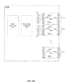
- FIG. 1A is a block diagram illustrating an exemplary Ethernet enabled communication device comprising a configurable Ethernet connector wherein various components may be present or absent based on an implementation and/or use of the connector, in accordance with an embodiment of the invention.
- FIG. 1B is a block diagram illustrating connectors which comprise electrical characteristics to indicate whether power is to be sourced or sinked, in accordance with an embodiment of the invention.
- FIG. 1C is a block diagram illustrating connectors which comprise electro-mechanical characteristics to indicate whether power is to be sourced or sinked, in accordance with an embodiment of the invention.
- FIG. 2A is a three dimensional representation of exemplary embodiments of Ethernet connectors, in accordance with an embodiment of the invention.
- FIG. 2B is a block diagram illustrating exemplary embodiments of a configurable connector for Ethernet applications, in accordance with an embodiment of the invention.
- FIG. 3 is a diagram illustrating termination of twisted pairs in a configurable Ethernet connector, in accordance with an embodiment of the invention.
- FIG. 4A depicts a block diagram illustrating ganging together of multiple connectors, in accordance with an embodiment of the invention.
- FIG. 4B is a three dimensional view of an Ethernet connector which may be ganged together with other connectors, in accordance with an embodiment of the invention.
- FIG. 4C is a diagram illustrating two ganged Ethernet connectors, in accordance with an embodiment of the invention.
- FIG. 5 is a diagram illustrating an example of an Ethernet connector with an integrated solid-state switch, in accordance with an embodiment of the invention.
- a configurable Ethernet connector residing in an Ethernet enabled communication device may couple the communication device to one or more twisted pairs and enable communication of Ethernet frames over the one or more twisted pairs. Conductors of each of the twisted pairs may make contact with adjacent pins of the configurable Ethernet connector.
- a size and shape of the configurable Ethernet connector may enable housing of more than 48 instances of the configurable Ethernet connector in a single standard size one rack unit face plate of a 19-inch rack.
- the configurable Ethernet connector may provide mechanical and electrical indications that enable a device coupled to the configurable Ethernet connector to determine configuration information of the configurable Ethernet connector.
- the information may indicate presence or absence of various components within and/or on the configurable Ethernet connector.
- the components may comprise a memory device which stores a configuration and/or capabilities of the configurable Ethernet connector.
- the components may comprise an Ethernet physical layer transceiver (PHY).
- the components may comprise one or more circuits and/or processors that are operable to manage supply power that may be sourced and/or sinked via the connector.
- the components may comprise a solid-state switch that is configurable via one or more control signals, and a configuration of the solid-state switch determines which pins of the Ethernet connector are coupled to which port(s) of an Ethernet PHY. The one or more control signals are generated by the Ethernet PHY.
- the configuration information may indicate whether the Ethernet device sources or sinks power.
- the configuration information may indicate which ones of the twisted pairs are to be utilized for communicating the Ethernet frames.
- the configuration information may indicate which ones of the twisted pairs are to be utilized for delivery of supply power.
- the configurable Ethernet connector may comprise one or more first interfaces that enable electrically coupling the connector to a cable assembly, one or more second interfaces that enable electrically coupling the configurable Ethernet connector to a device that the configurable Ethernet connector is mounted within or on, and one or more third interfaces that enable electrically coupling the configurable Ethernet connector to a corresponding one or more other connectors that are mounted on or within the device.
- the configurable Ethernet connector may support one or more of 10BASE-T, 100BASE-T, 1GBASE-T, 10GBASE-T, 40GBASE-T. and 100GBASE-T.
- FIG. 1A is a block diagram illustrating an exemplary Ethernet enabled communication device comprising a configurable Ethernet connector wherein various components may be present or absent based on an implementation and/or use of the connector, in accordance with an embodiment of the invention.
- a networking enabled device 102 a may comprise a host subsystem 104 , a networking subsystem 106 , and a configurable Ethernet connector 112 .
- the networking enabled device 102 a may comprise suitable logic, circuitry, interfaces and/or code that may be operable to perform computing and/or networking functions.
- An exemplary networking enabled device 102 a may comprise a router, a switch, a patch panel, a laptop, a portable phone, a media player, a location device, a television, a set-top-box, a camera and/or a gaming device.
- the networking enabled device 102 a may be operable to communicate via the connection system 134 based on a plurality of different standardized and/or non-standardized communication protocols and/or communication technologies, for example, based on various Ethernet protocols.
- the host subsystem 104 may comprise suitable logic, circuitry, interfaces, and/or code that may be operable to perform computations and/or executing instructions in the networking enabled device 102 a .
- the host subsystem 104 may comprise one or more state machines and/or may run an operating system.
- the host subsystem 104 may perform computations and/or execute instructions to generate messages for transmission via the networking subsystem 106 .
- the host subsystems 104 may perform computations and/or execute instructions to process messages received via the networking subsystem 106 .
- the host subsystem 104 may interface with the networking subsystem 106 via a data bus 107 which may be, for example, a PCI-X bus.
- the host subsystem 104 may interface with various components in the connector 112 via one or more signals 105 .
- the signals 105 may, for example, comprise one or more discrete control signals and/or one or more of the signals 105 may be communicated via a data bus such as an I 2 C bus or SMBus.
- the networking subsystem 106 may comprise suitable logic, circuitry, interfaces, and/or code that may be operable to handle functionality of OSI layer 1 and higher OSI layers in the networking enabled device 102 a , respectively.
- the networking subsystem 106 may be operable to implement switching, routing, and/or network interface card (NIC) functions.
- the networking subsystem 106 may be operable to implement Ethernet protocols, such as those based on the IEEE 802.3 standard, for example, but is not limited in this regard.
- the networking subsystem 106 may comprise, for example, a media access control (MAC) controller 108 . However, in some instances the MAC 108 , or portions thereof, may be integrated into the connector 112 .
- the networking subsystem 106 may comprise, for example, an Ethernet physical layer device (PHY) 116 . However, in some instances the Ethernet PHY 116 may be integrated into the connector 112 .
- PHY Ethernet physical layer device
- the connection system 134 may comprise the configurable Ethernet connector 112 , a cable 133 , and another connector or termination (not shown) on a link partner.
- the cable 133 may comprise the connector 120 , one or more twisted pairs 126 , and one or more connectors or other terminations (not shown) on the opposite end.
- the twisted pairs 126 may comprise, for example, insulated twisted pairs of aluminum or copper. Characteristics of the cable 133 , such as number of twisted pairs 126 within the cable 133 , presence of shielding 132 , length of the cable 133 , and/or wire gauge used for the twisted pairs 126 may determine which protocols and/or which data rates the cable 133 may be operable to support.
- the optional shield 132 may comprise, for example, foil and/or a braided sheath around and/or along a length of one or more twisted pairs.
- one or more individual twisted pairs 126 may be shielded via one or more corresponding shields 132 , and/or a plurality of twisted pairs 126 may be encased in a single shield 132 .
- the optional shield 132 may be grounded by the networking enabled device 102 a via the connector 112 , for example.
- the connectors 112 and 120 may enable coupling the device 102 a to the cable 133 .
- the connector 112 and the connector 120 may be suited for Ethernet communications and the connectors 112 and 120 may be small enough to fit into a handheld device and/or small enough such that more than 48 of the connectors 112 and/or 120 may fit into a standard size one rack unit face plate of a 19-rack rack.
- the pins 119 0 - 119 N may be in conductive contact with the pins 113 0 - 113 N , respectively.
- the term “connector” is used generically herein to encompass both receptacles and plugs. In this regard, whether a connector is a receptacle that accepts a plug or whether a connector is a plug that inserts into a receptacle may be implementation dependant and unimportant in various embodiments of the invention.
- the connection system 134 may comprise various characteristics. Such characteristics may include the length of the cable 133 , the gauge of the wires of the twisted pairs 126 , the presence or absence of the shielding 132 , and the type of shielding 132 . A system designer may select a particular characteristics, that is, select a particular configuration of the connection platform 134 , based on, for example, the amount and/or type of data the device 102 a the device is expected to handle, the environment in which the connection platform resides, whether energy efficiency is a priority for the device 102 a , and/or a desired cost and/or performance of the system 100 . In order to ensure compatibility between various portions of the connection platform 134 , the connector 112 and/or the connector 120 may be keyed or comprise some other mechanical means for ensuring that only connectors 112 and 120 having compatible configurations may be mated.
- Characteristics of the connection platform may also include a configuration of the connector 112 and/or the connector 120 .
- the connectors 112 and 120 may be configurable in a variety of ways.
- the connectors 112 and/or 120 may be configurable is that the number and placement of the pins 113 may be variable.
- the connector 112 and/or the connector 120 may comprise more pins for interfacing to more twisted pairs and in some configurations it may have fewer pins for interfacing with fewer twisted pairs.
- the type of pins may refer to, for example, the material the pins are made of, e.g., gold, copper, aluminum, or tin. Additionally or alternatively, the type of pins may refer to the function of the pins.
- the connector 112 and/or the connector 120 may comprise sense pins or other pins that indicate a configuration of the connector 112 and/or the connector 120 .
- the connectors 112 and/or 120 may be configurable. That is, various configurations of the connector 112 and/or 120 may have various electronic components installed, e.g., by soldering them to a PCB, or not installed.
- the connectors 112 and/or 120 may each comprise a printed circuit board (PCB) having solder lands that accept various components, and different configurations of the connector 112 and/or the connector 120 may have different components populated and unpopulated and/or may have different versions of components populated.
- PCB printed circuit board
- different versions of components may comprise different models of the components having different capabilities or features.
- Exemplary components which may or may not be populated within and/or on the connector 112 and/or 120 may comprise, for example, a media access controller (MAC) or MAC functions 108 , a physical layer transceiver (PHY) 116 , a non-volatile memory (NVM) 150 , a power over Ethernet (PoE) module 113 , a module 154 that configures whether power is sourced or sunk by the device 102 a , magnetics 114 , one or more light emitting diodes (LEDs) 152 , and a module 158 which may be operable to participate in network management protocols.
- MAC media access controller
- PHY physical layer transceiver
- NVM non-volatile memory
- PoE power over Ethernet
- module 154 that configures whether power is sourced or sunk by the device 102 a
- magnetics 114 magnetics 114
- LEDs light emitting diodes
- module 158 which may be operable to participate in network management protocols.
- the MAC 108 may comprise suitable logic, circuitry, interfaces, and/or code that may be operable to perform data encapsulation and/or media access management, where media access management may comprise operations that handle conflicts arising from multiple networking enabled devices sharing the cable 133 and/or from multiple applications, processes, or virtual machines within the networking enabled device 102 a sharing the connection system 134 .
- each MAC 108 may provide an interface between the PHY 116 and the host subsystem 104 .
- Each MAC 108 may communicate with the PHY 116 via a media independent interface (xxMII).
- xxMII media independent interface
- GMII gigabit MII
- RMII reduced full MII
- XGMII 10 gigabit MII
- the xxMII may comprise a carrier sense signal (CRS) which may be utilized to manage a rate at which data is communicated between the PHY 116 and the MAC 108 .
- CRS carrier sense signal
- integrating the MAC 108 , or portions thereof operable to implement MAC functions, into the connector 112 may enable the connector 112 may handle media access.
- multiple connectors 112 with integrated MAC functions may replace a single legacy connector.
- multiple connectors 112 may fit into the solder land pattern and area of the device 102 a previously occupied by a legacy connector. In this way, the number of ports on the networking device 102 a may be increased by replacing the single legacy connector with a plurality of connectors 112 .
- the PHY 116 may comprise, for example, a twisted pair Ethernet PHY capable of operating at a variable data rate.
- each PHY 116 may be operable to adjust a data rate at which it communicates based on characteristics of the connection system 134 via which it communicates.
- the PHY 116 may, for example, enable multi-rate Ethernet communications.
- the PHY 116 may be operable to communicate at any of 10 Mbps, 100 Mbps, 1 Gbps, 2.5 Gbps, 4 Gbps, 8 Gbps, 10 Gbps, 40 Gbps and 100 Gbps.
- the networking subsystem 106 may support standard-based data rates and/or nonstandard data rates.
- the PHY 116 may be operable to achieve various data rates and/or implement various Ethernet protocols via configuration of various parameters.
- Exemplary parameters that may be configured in the PHY 116 to control the data rate may comprise the number of twisted pairs 126 over which the PHY 116 communicates, which one(s) of the twisted pairs over which the PHY 116 communicates, the symbol rate at which the PHY 116 operates, the encoding or modulation scheme utilized by the PHY 116 , the inter-frame gap time, various buffer sizes, and/or various thresholds.
- the PHY 116 may be configured based on the traffic that it handles. For example, if traffic is heavier in one direction than in the other direction, the PHY 116 may be configured to operate in an asymmetrical mode where outbound data and inbound data may be communicated at different rates.
- the rate at which the PHY 116 communicates and the number of channels over which the PHY 116 communicates may be determined based on characteristics of the connection system 134 .
- the PHY 116 may be operable to communicate at higher rates and/or via more channels when coupled to shorter and/or larger diameter cabling, and communicate at lower rates and/or via fewer channels when coupled to longer and/or smaller diameter cabling. Additional details regarding a connector comprising an integrated PHY are described in co-pending U.S. patent application Ser. No. 12/702,173 referenced above.
- the NVM 150 may comprise, for example, a programmable ROM which may store information about the connector 112 .
- the host subsystem 104 and/or the networking subsystem 106 may be operable to read the contents of the NVM 150 to determine characteristics of the connector 112 .
- the contents of the NVM 150 may indicate whether various components are present in the connector 112 and/or a configuration of components present in the connector 112 . Additional details regarding a connector comprising an integrated NVM are described in co-pending U.S. patent application Ser. No. 12/731,033 referenced above.
- the PoE module 118 may comprise suitable logic, circuitry, interfaces, and/or code operable to condition, regulate, and/or otherwise manage or control supply power available and/or drawn via the connection system 134 . Additional details of a connector comprising an integrated PoE module are described in co-pending U.S. patent application Ser. No. 12/752,065 referenced above.
- the module 154 may comprise suitable logic, circuitry, interfaces, and/or code operable to configure the connector 112 based on whether the device 102 a sources and/or sinks supply power via the connector 112 . Additional details of a connector comprising an integrated module such as the module 154 are described in co-pending U.S. patent application Ser. No. 12/828,484 referenced above.
- the magnetics 114 may comprise suitable logic, circuitry, interfaces, and/or code that may be operable to couple the signal bus 117 to pins 113 of the connector 112 .
- the magnetics 114 may provide noise and/or EMI suppression and/or may impedance match the signal bus 117 to the connector 120 and the twisted pairs 126 .
- the magnetics 114 may comprise one or more transformers and/or one or more inductive chokes.
- the magnetics 114 may also comprise other components such as resistors, capacitors, and/or inductors for achieving impedance matching, isolation, and/or noise and/or EMI suppression.
- whether the magnetics 114 , or portions thereof, are populated in the connector 112 may depend on, for example, the noise that the networking device 102 a is expected to tolerate, the length of the cable 133 over which the networking device 102 a will be expected to communicate, and/or whether the networking subsystem 102 a will be tied to a fixed potential, e.g., “grounded,” or whether it will be “floating.” In this manner, by populating or not populating the magnetics 114 , or portions thereof, different variants of the connector 112 may be manufactured for different use cases. Additional details of a connector comprising integrated magnetics are described in one or more of the co-pending United States Patent Applications referenced above.
- the LED(s) 150 may be operable to indicate characteristics and/or status of the connection system 134 .
- the LED(s) 150 may indicate whether the connector 112 and 120 are properly mated, whether the shield 134 is present, whether data is being communicated over the cable 133 , a length of the cable 133 , whether the opposite end of the cable 133 is mated with a networking enabled device, whether various components are present in the connector 112 and/or 120 , and/or a configuration of one or more components present in the connector 112 and/or 120 . Additional details of a connector comprising one or more integrated LEDs are described in one or more of the co-pending United States Patent Applications referenced above.
- the module 156 may comprise suitable logic, circuitry, interfaces, and/or code operable to implement one or more network management protocols such as simple network management protocol (SNMP), link layer discovery protocol (LLDP), and data center bridging exchange (DCBX) may be integrated on and/or within the connector 112 and/or the connector 120 .
- network management protocols such as simple network management protocol (SNMP), link layer discovery protocol (LLDP), and data center bridging exchange (DCBX) may be integrated on and/or within the connector 112 and/or the connector 120 .
- packets in accordance with one or more network management protocols may be generated and/or parsed or deconstructed in the connector 112 and/or the connector 120 . That is, one or more network management protocols may be terminated in the connector 112 and/or the connector 120 .
- various components of the connector 112 and/or other portions of the networking enabled device 102 a may be configured and/or otherwise managed based on management information received over a network.
- information recovered from one or more LLDP packet may be
- the networking enabled device 102 a may be operable to determine characteristics of the connection system 134 . Such a determination may result from an electrical and/or mechanical indication provided by the connector 112 and/or 120 .
- the type of pins may refer to the function of the pins.
- the connector 112 and/or the connector 120 may comprise sense pins or other pins that indicate a configuration of the connector 112 and/or the connector 120 .
- a first set of electrical and/or mechanical features on a connector 120 may indicate a first configuration and a second set of electrical or mechanical features on a connector 120 may indicate a second configuration.
- FIG. 1B illustrates a an exemplary embodiment of the invention in which connector 120 A comprises a conductor 150 which ties the sense pin to V+ to indicate a first configuration, and a connector 1203 comprises a conductor 152 which ties the sense pin to V ⁇ to indicate a second configuration.
- the connector 112 comprises contacts 160 A and 160 B, which, when shorted together, may indicate a first configuration and when not electrically shorted may indicate a second configuration.
- the connector 120 may comprise a knock-out 162 which may electrically short the contacts 160 A and 160 B when present and may leave the contacts 160 A and 160 B open circuited when absent.
- the connector 120 A may indicate that it configured one way and the connector 1203 may indicate that it is configured another way.
- the indication may comprise transient signals generated by components integrated into the connector 112 and/or the connector 120 .
- the data may be read out from the NVM 150 and communicated to the device 102 a and/or to the device (not shown) coupled to the other end of the cable 133 .
- the module 156 and the PHY 116 may interact to send one or more messages in accordance with a management protocols.
- the management protocol message(s) may be sent to the device 102 a and/or to the device on the other end of the cable 133 .
- Characteristics of the connection platform 134 may determine a mode of operation of the device 102 a . For example, a data rate at which the device 102 a communicates over the connection platform 134 , which protocols are supported by the device 102 a , whether the device 102 a supplies or sinks power via the connection platform 134 , and an amount of power supplied or sinked by the device 102 a via the connection platform 134 may be determined based on characteristics of the connection platform 134 .
- FIG. 2A is a three dimensional representation of exemplary embodiments of Ethernet connectors, in accordance with an embodiment of the invention. Referring to FIG. 1 , there is shown the connector 112 , the connector 120 , and a portion of the cable 133 .
- the connector 112 depicted in FIG. 2A may comprise a modular housing that may be operable to be stacked, ganged and/or installed in a networking device a space-efficient and/or uniform manner.
- Materials utilized for housing of the Ethernet connectors 110 and/or 150 may vary.
- the housing may be made of non-conducting and/or conducting materials such as plastic and/or metal.
- the Ethernet connectors 112 and/or 120 may be shielded or unshielded.
- the Ethernet connector 112 may be a receptacle connector that may comprise a modular housing and the Ethernet connector 120 may be a corresponding Ethernet connector which may be referred to as a plug.
- the Ethernet connector 112 may comprise a keyed receptacle area 204 and the Ethernet connector 120 may comprise a complimentary exterior contour that may enable mating of the connectors in a proper orientation such that the connectors are not misaligned and/or damaged.
- the invention is not limited to any specific shape of the keyed receptacle area 204 and/or of the corresponding exterior contour of the Ethernet connector 120 and any suitable shapes may be utilized.
- various components 202 may be integrated within and/or on the connector 112 and/or the connector 120 .
- the components 202 may comprise, for example, integrated circuits and/or passive components.
- one or more of the components may comprise a printed circuit board to which one or more other components are soldered.
- the Ethernet connector 112 may be configured to be coupled to a circuit board in a communication device, to be installed in a patch panel or a wall mount and/or to be coupled to a cable, for example.
- the Ethernet connector 112 and/or the Ethernet connector 120 may comprise dimensions that are smaller than a conventional Ethernet connector, such as an eight position eight conductor (8P8C) modular connector, often referred to as an RJ45 connector.
- 8P8C eight position eight conductor
- RJ45 connector an eight position eight conductor
- the Ethernet connector 112 and/or the Ethernet connector 150 may be small enough to be installed in a handheld device, such as a mobile phone or smart phone.
- the Ethernet connector 112 and/or the Ethernet connector 120 may be small enough such that greater than 48 connectors or connector modules may be installed in a 1 rack unit (RU) patch panel or switch.
- RU rack unit
- a plurality of connectors 112 may fit in a housing which would fit only one conventional Ethernet connector.
- a conventional Ethernet connector 212 and two connectors 212 A and 212 B there is shown a conventional Ethernet connector 212 and two connectors 212 A and 212 B.
- the connector 212 A may effectively comprise two instances of connector 112 described above, and the connector 212 B may effectively comprise four instances of the connector 112 .
- the connector 220 A and/or the connector 220 B may have the same solder land pattern as an existing Ethernet connector. In this manner, the connector 120 A and the connector 120 B may be “dropped in” to an existing PCB designed to accept a conventional Ethernet connector.
- replacing the connector 201 with the connector 212 A may enable replacing a single Ethernet port with multiple Ethernet ports.
- one of the receptacles of the connector 212 A may be only for charging and the other may be for Ethernet communications.
- various configurations of the Ethernet connectors 112 and/or 120 that may be operable to communicate at higher data rates and/or may provide higher levels of performance for a given rate may be referred to as higher performance or higher end configurations.
- various configurations of the Ethernet connectors 112 and/or 120 that may be operable to communicate only at lower data rates and/or may provide lower levels of performance for a given data rate may be referred to as lower cost or lower end configurations.
- higher end configurations of the Ethernet connectors 112 and/or 120 may comprise a greater number of conductor contacts, may be made with superior materials than lower end versions, may comprise shielding and/or better grounding, and/or may have one or more components 202 , for providing additional functionality, integrated therein.
- Ethernet connectors 112 and/or 120 may vary, the various configurations may comprise the same or a similar general form factor.
- the Ethernet connectors may be operable to be coupled and may communicate at a data rate and/or at a level of performance that is determined based on their similar configurations.
- the coupled Ethernet connectors 112 and 120 may comprise different configurations, for example, when one connector may comprise a higher end configuration and the corresponding connector may comprise a lower end configuration, the Ethernet connectors may be operable to be coupled, however, they may only be operable to communicate at a data rate and/or at a level of performance that is supported by the lower end configuration.
- the Ethernet connectors 112 and 120 may each have 12 positions for pins.
- FIG. 3 is a diagram illustrating termination of twisted pairs in a configurable Ethernet connector, in accordance with an embodiment of the invention.
- FIG. 3 there is shown termination of four twisted pairs 126 1 - 126 4 in a conventional Ethernet connector 220 and in an exemplary configuration of the connectors 120 .
- Each of the twisted pairs 128 1 - 126 4 may comprise a conductor x and a conductor y.
- the x and y conductors of twisted pair 126 2 a terminated in non-adjacent pins 219 2 and 219 5 which, when the connectors 212 and 220 are mated, make contact with the pins 213 2 and 213 5 , respectively.
- Twisted pair 126 1 is terminated in adjacent pins 119 0 and 119 1 which, when connectors 112 and 120 are mated, make contact with pins 113 0 and 113 1 , respectively.
- Twisted pair 126 2 is terminated in adjacent pins 119 2 and 119 3 , which, when connectors 112 and 120 are mated, make contact with pins 113 2 and 113 3 , respectively.
- Twisted pair 126 3 is terminated in adjacent pins 119 4 and 119 5 , which, when connectors 112 and 120 are mated, make contact with pins 113 4 and 113 5 , respectively.
- Twisted pair 126 4 is terminated in adjacent pins 119 6 and 119 7 , which, when connectors 112 and 120 are mated, make contact with pins 113 6 and 113 7 , respectively.
- FIG. 4A depicts a block diagram illustrating ganging together of multiple connectors, in accordance with an embodiment of the invention.
- a networking device 102 b comprising a plurality, X, of connectors 112 , where X is an integer greater than 1.
- the networking device 102 b may be substantially similar to the networking device 102 a described above.
- Each of the connectors 112 1 - 112 X may comprise a first interface 402 for coupling, via a printed circuit board, with the other subsystems of the networking device 102 b , interfaces 404 L and 404 R for coupling with other connectors 112 , and an interface 406 for coupling with a corresponding connector 120 .
- the connectors 112 may be modular in that connectors 112 may be added or removed with lithe or no changes and/or reconfiguration of the networking subsystem 106 and/or host subsystem 104 .
- the connectors 112 may be “plug and play” upon addition of a connector 112 , the connector may be enumerated with a unique address and controlled by the host subsystem 104 via the signals 105 and/or one of the connectors 112 may assume the role of master and may control the remaining connectors which may assume the role of slaves.
- Each of the interfaces 402 , 404 , and 406 of a connector 112 may comprise one or more contacts which may comprise, for example, pins and/or solder bumps.
- the connector 112 1 may be coupled to a data bus 117 , and maybe one or more voltage rails and/or control signals, via the interface 402 of the connector 112 1 .
- the connector 112 1 may be coupled to connector 112 2 via the interface 404 L of the connector 112 1 and the interface 404 R of the connector 112 2 .
- a connector 112 3 if present, may be similarly coupled to the connector 112 2 , a connector 112 4 to the connector 112 3 , and so forth, up to connector 112 X . In this manner, the connectors 112 1 - 112 x , may be coupled, or “ganged,” together in a daisy-chain fashion.
- various ones of the connectors 112 1 - 112 X may be of various configurations. For example, some may be high performance configurations and some may be low cost configurations. As another example, some may have integrated PoE and/or power management components and some may not. Similarly, some may be have integrated components for participating in management protocols and some may not.
- FIG. 4B is a three dimensional view of an Ethernet connector which may be ganged together with other connectors, in accordance with an embodiment of the invention.
- the interface 402 L of the connector 112 is shown in FIG. 4B .
- the size, shape, and number of contacts or pins of the interface 402 L is not limited to that depicted in the figure.
- FIG. 4C is a diagram illustrating two ganged Ethernet connectors, in accordance with an embodiment of the invention. Referring to FIG. 4C , it is shown how a first connector 112 a may be coupled to a second connector via the interfaces 402 R of the connector 112 a and the interface 402 L of the connector 112 b . Although, FIG. 4C shows the connectors 112 a and 112 b with some distance between them in order to illustrate the contact of the interfaces, in various embodiments of the invention, the wall of connector 112 a may sit flush with the wall of connector 112 b.
- FIG. 5 is a diagram illustrating an example of an Ethernet connector with an integrated solid-state switch, in accordance with an embodiment of the invention.
- a front view of an exemplary Ethernet connector 112 comprising four pairs of pins 504 a - 504 d and a solid-state switch 502 integrated within and/or on the Ethernet connector 112 .
- four pairs of pins 504 are shown, any number of pins may be present for interfacing to any number of twisted-pairs.
- the solid-state switch 502 may comprise, for example, a discrete integrated circuit or may be integrated on a common substrate with other components, such as the Ethernet PHY 116 .
- the Ethernet PHY 116 may be as described above and may comprise a plurality of ports 512 . Although the PHY 116 is shown as comprising two ports, the Ethernet PHY may comprise any number of ports.
- the PHY 116 may configure the switch 502 to configure which pin-pair 502 is coupled to which port 512 .
- port 512 a may be coupled to pin-pair 504 a and port 512 b may be coupled to port 512 b
- port 512 a may be coupled to pin-pair 504 c and port 512 b may be coupled to port 512 d
- port 512 a may be coupled to pin-pair 504 a and port 512 b may be coupled to port 512 d
- port 512 a may be coupled to pin-pair 504 a and port 512 b may be coupled to port 512 d .
- the PHY 116 may determine which configuration to select based on, for example, characteristics of the cable coupled to the connector 112 and/or characteristics of a link partner coupled to the connector 112 via a cable. For simplex communications, the Ethernet PHY 116 may configure the switch 502 to match the configuration of a link partner.
- port 512 a may be an ingress port and port 512 c may be an egress port. Accordingly, the switch 502 may be configured such that port 512 a is coupled to a twisted pair on which a link partner transmits and port 512 b is coupled to a twisted pair on which the link partner receives.
- Various aspects of a method and system for a configurable connector for Ethernet application may comprise an Ethernet connector 112 residing in an Ethernet enabled communication device 102 a .
- the connector 112 may couple the communication device 102 a to one or more twisted pairs 126 and enable communication of Ethernet frames over the one or more twisted pairs 126 .
- Conductors x and y of each of the twisted pairs 126 may make contact with adjacent pins 113 of the configurable Ethernet connector 112 .
- a size and shape of the configurable Ethernet connector 112 may enable housing more than 48 instances of the configurable Ethernet connector 112 in a single standard size one rack unit face plate of a 19-inch rack.
- the configurable Ethernet connector 112 may provide mechanical and electrical indications that enable the device 102 a and/or a remote device coupled to the configurable Ethernet connector 112 to determine configuration information of the configurable Ethernet connector 112 .
- the information may indicate presence or absence of various components within and/or on the configurable Ethernet connector 112 .
- the components may comprise a memory device 150 which stores a configuration and/or capabilities of the configurable Ethernet connector 112 .
- the components may comprise an Ethernet physical layer transceiver (PHY) 116 .
- the components may comprise one or more circuits and/or processors 118 and/or 154 that are operable to manage supply power that may be sourced and/or sinked via the connector.
- the components may comprise a solid-state 502 switch that is configurable via one or more control signals 510 , and a configuration of the solid-state switch 502 may determine which pins 113 of the Ethernet connector 112 are coupled to which port(s) 512 of an Ethernet PHY 116 .
- the one or more control signals 510 are generated by the Ethernet PHY 116 .
- the configuration information may indicate whether the Ethernet device 102 a sources or sinks power.
- the configuration information may indicate which ones of the twisted pairs 126 are to be utilized for communicating the Ethernet frames.
- the configuration information may indicate which ones of the twisted pairs 126 are to be utilized for deliver of supply power.
- the configurable Ethernet connector 112 may comprise one or more first interfaces 406 that enable electrically coupling the connector to a cable assembly 133 , one or more second interfaces 402 that enable electrically coupling the connector to a device that the connector is mounted within or on, and one or more third interfaces 404 that enable electrically coupling the configurable Ethernet connector 112 to a corresponding one or more other configurable Ethernet connectors 112 that are mounted on or within the device 102 a .
- the configurable Ethernet connector 112 may support one or more of 10BASE-T, 100BASE-T, 1GBASE-T, 10GBASE-T, 40GBASE-T, and 100GBASE-T.
- inventions may provide a non-transitory computer readable medium and/or storage medium, and/or a non-transitory machine readable medium and/or storage medium, having stored thereon, a machine code and/or a computer program having at least one code section executable by a machine and/or a computer, thereby causing the machine and/or computer to perform the steps as described herein for a configurable connector for Ethernet.
- the present invention may be realized in hardware, software, or a combination of hardware and software.
- the present invention may be realized in a centralized fashion in at least one computer system, or in a distributed fashion where different elements are spread across several interconnected computer systems. Any kind of computer system or other apparatus adapted for carrying out the methods described herein is suited.
- a typical combination of hardware and software may be a general-purpose computer system with a computer program that, when being loaded and executed, controls the computer system such that it carries out the methods described herein.
- the present invention may also be embedded in a computer program product, which comprises all the features enabling the implementation of the methods described herein, and which when loaded in a computer system is able to carry out these methods.
- Computer program in the present context means any expression, in any language, code or notation, of a set of instructions intended to cause a system having an information processing capability to perform a particular function either directly or after either or both of the following: a) conversion to another language, code or notation; b) reproduction in a different material form.
Abstract
Description
Claims (20)
Priority Applications (1)
| Application Number | Priority Date | Filing Date | Title |
|---|---|---|---|
| US13/430,374 US8843678B2 (en) | 2010-07-16 | 2012-03-26 | Method and system for a configurable connector for ethernet applications |
Applications Claiming Priority (3)
| Application Number | Priority Date | Filing Date | Title |
|---|---|---|---|
| US36518910P | 2010-07-16 | 2010-07-16 | |
| US12/853,945 US8145814B2 (en) | 2010-07-16 | 2010-08-10 | Method and system for a configurable connnector for ethernet |
| US13/430,374 US8843678B2 (en) | 2010-07-16 | 2012-03-26 | Method and system for a configurable connector for ethernet applications |
Related Parent Applications (1)
| Application Number | Title | Priority Date | Filing Date |
|---|---|---|---|
| US12/853,945 Continuation US8145814B2 (en) | 2010-07-16 | 2010-08-10 | Method and system for a configurable connnector for ethernet |
Publications (2)
| Publication Number | Publication Date |
|---|---|
| US20120246358A1 US20120246358A1 (en) | 2012-09-27 |
| US8843678B2 true US8843678B2 (en) | 2014-09-23 |
Family
ID=45467330
Family Applications (2)
| Application Number | Title | Priority Date | Filing Date |
|---|---|---|---|
| US12/853,945 Active 2030-09-16 US8145814B2 (en) | 2010-07-16 | 2010-08-10 | Method and system for a configurable connnector for ethernet |
| US13/430,374 Active US8843678B2 (en) | 2010-07-16 | 2012-03-26 | Method and system for a configurable connector for ethernet applications |
Family Applications Before (1)
| Application Number | Title | Priority Date | Filing Date |
|---|---|---|---|
| US12/853,945 Active 2030-09-16 US8145814B2 (en) | 2010-07-16 | 2010-08-10 | Method and system for a configurable connnector for ethernet |
Country Status (1)
| Country | Link |
|---|---|
| US (2) | US8145814B2 (en) |
Cited By (1)
| Publication number | Priority date | Publication date | Assignee | Title |
|---|---|---|---|---|
| US10848404B2 (en) | 2017-10-16 | 2020-11-24 | Richard Mei | LAN cable conductor energy measurement, monitoring and management system |
Families Citing this family (14)
| Publication number | Priority date | Publication date | Assignee | Title |
|---|---|---|---|---|
| US8145814B2 (en) * | 2010-07-16 | 2012-03-27 | Broadcom Corporation | Method and system for a configurable connnector for ethernet |
| US8419444B2 (en) * | 2010-09-16 | 2013-04-16 | Mellanox Technologies Ltd. | Adapter for high-speed ethernet |
| US8638651B2 (en) | 2011-01-21 | 2014-01-28 | Commscope, Inc. Of North Carolina | Intelligent patching systems and methods using phantom mode control signals and related communications connectors |
| ES2639553T3 (en) * | 2012-03-16 | 2017-10-27 | Tyco Electronics Uk Ltd. | Smart wall plate and modular connectors for secure network access and / or VLAN configuration |
| US10135626B2 (en) * | 2015-04-14 | 2018-11-20 | Avago Technologies General Ip (Singapore) Pte. Ltd. | Power coupling circuits for single-pair ethernet with automotive applications |
| US10185100B2 (en) * | 2017-01-30 | 2019-01-22 | Senko Advanced Components, Inc | Modular connector and adapter assembly using a removable anchor device |
| US10284180B2 (en) * | 2017-06-09 | 2019-05-07 | Nxp B.V. | Circuits for correction of signals susceptible to baseline wander |
| US10644472B2 (en) | 2017-06-28 | 2020-05-05 | Mellanox Technologies, Ltd. | Cable adapter |
| US10128627B1 (en) | 2017-06-28 | 2018-11-13 | Mellanox Technologies, Ltd. | Cable adapter |
| US10705309B2 (en) | 2018-06-06 | 2020-07-07 | Mellanox Technologies, Ltd. | RF EMI reducing fiber cable assembly |
| US10444453B1 (en) | 2018-07-25 | 2019-10-15 | Mellanox Technologies, Ltd. | QSFP-DD to SFP-DD adapter |
| US10741954B1 (en) | 2019-03-17 | 2020-08-11 | Mellanox Technologies, Ltd. | Multi-form-factor connector |
| US11240061B2 (en) * | 2019-06-03 | 2022-02-01 | Progress Rail Locomotive Inc. | Methods and systems for controlling locomotives |
| US11169330B2 (en) | 2019-10-24 | 2021-11-09 | Mellanox Technologies Tlv Ltd. | Wavelength-splitting optical cable |
Citations (19)
| Publication number | Priority date | Publication date | Assignee | Title |
|---|---|---|---|---|
| US5892926A (en) | 1996-12-30 | 1999-04-06 | Compaq Computer Corporation | Direct media independent interface connection system for network devices |
| US6794577B1 (en) | 2003-03-27 | 2004-09-21 | International Business Machines Corporation | Configurable cable for use in a data processing network |
| US6934788B2 (en) | 1999-07-08 | 2005-08-23 | Intel Corporation | Port expansion peripheral module system |
| US20050287873A1 (en) * | 2004-06-24 | 2005-12-29 | Carroll James A | Network connection system |
| US20060116023A1 (en) | 2004-09-20 | 2006-06-01 | Spitaels James S | Equipment rack data/power distribution |
| US20060160407A1 (en) * | 2004-06-24 | 2006-07-20 | Carroll James A | Network connection system |
| US7185045B2 (en) | 2002-07-15 | 2007-02-27 | Sixnet, Llc | Ethernet interface device for reporting status via common industrial protocols |
| US20070110026A1 (en) * | 2005-11-14 | 2007-05-17 | Airdefense, Inc. | Systems and methods for dual power and data over a single cable |
| US20070288125A1 (en) * | 2006-06-09 | 2007-12-13 | Mks Instruments, Inc. | Power Over Ethernet (Poe) - Based Measurement System |
| US20080013457A1 (en) * | 2003-07-02 | 2008-01-17 | Broadcom Corporation | Full channel-swap |
| US20090142965A1 (en) | 2004-07-28 | 2009-06-04 | American Power Conversion | Multi-port cabling system and method |
| US20090316722A1 (en) * | 2008-06-20 | 2009-12-24 | Infineon Technologies Ag | Multi-Mode Ethernet Transceiver |
| US20100049893A1 (en) | 2008-08-25 | 2010-02-25 | Barracuda Networks, Inc | Link balancer apparatus with low profile plural port input / output card |
| US7774628B2 (en) | 2006-05-25 | 2010-08-10 | Foundry Networks, Inc. | Enabling/disabling power-over-ethernet software subsystem in response to power supply status |
| US20110217009A1 (en) * | 2010-03-04 | 2011-09-08 | Fujitsu Network Communications, Inc. | System for Mounting Optical Modules in an Optical Network |
| US20110243151A1 (en) * | 2010-04-06 | 2011-10-06 | Wael William Diab | Method And System For Connector And/Or Cable With Configurable Antenna For Ethernet And Wireless Applications |
| US20110258464A1 (en) | 2010-04-16 | 2011-10-20 | Silicon Laboratories, Inc. | Circuit and Method for Detecting a Legacy Powered Device in a Power over Ethernet System |
| US20120015552A1 (en) * | 2010-07-16 | 2012-01-19 | Wael William Diab | Method and system for a configurable connnector for ethernet |
| US8355404B2 (en) * | 2006-09-06 | 2013-01-15 | Broadcom Corporation | Method and system for an asymmetric PHY in extended range ethernet LANs |
-
2010
- 2010-08-10 US US12/853,945 patent/US8145814B2/en active Active
-
2012
- 2012-03-26 US US13/430,374 patent/US8843678B2/en active Active
Patent Citations (22)
| Publication number | Priority date | Publication date | Assignee | Title |
|---|---|---|---|---|
| US5892926A (en) | 1996-12-30 | 1999-04-06 | Compaq Computer Corporation | Direct media independent interface connection system for network devices |
| US6934788B2 (en) | 1999-07-08 | 2005-08-23 | Intel Corporation | Port expansion peripheral module system |
| US7185045B2 (en) | 2002-07-15 | 2007-02-27 | Sixnet, Llc | Ethernet interface device for reporting status via common industrial protocols |
| US6794577B1 (en) | 2003-03-27 | 2004-09-21 | International Business Machines Corporation | Configurable cable for use in a data processing network |
| US20040188129A1 (en) | 2003-03-27 | 2004-09-30 | International Business Machines Corporation | Configurable cable for use in a data processing network |
| US20080013457A1 (en) * | 2003-07-02 | 2008-01-17 | Broadcom Corporation | Full channel-swap |
| US20050287873A1 (en) * | 2004-06-24 | 2005-12-29 | Carroll James A | Network connection system |
| US20060160407A1 (en) * | 2004-06-24 | 2006-07-20 | Carroll James A | Network connection system |
| US7229309B2 (en) * | 2004-06-24 | 2007-06-12 | James A. Carroll | Network connection system |
| US20090142965A1 (en) | 2004-07-28 | 2009-06-04 | American Power Conversion | Multi-port cabling system and method |
| US20060116023A1 (en) | 2004-09-20 | 2006-06-01 | Spitaels James S | Equipment rack data/power distribution |
| US20070110026A1 (en) * | 2005-11-14 | 2007-05-17 | Airdefense, Inc. | Systems and methods for dual power and data over a single cable |
| US7774628B2 (en) | 2006-05-25 | 2010-08-10 | Foundry Networks, Inc. | Enabling/disabling power-over-ethernet software subsystem in response to power supply status |
| US20070288125A1 (en) * | 2006-06-09 | 2007-12-13 | Mks Instruments, Inc. | Power Over Ethernet (Poe) - Based Measurement System |
| US8355404B2 (en) * | 2006-09-06 | 2013-01-15 | Broadcom Corporation | Method and system for an asymmetric PHY in extended range ethernet LANs |
| US20090316722A1 (en) * | 2008-06-20 | 2009-12-24 | Infineon Technologies Ag | Multi-Mode Ethernet Transceiver |
| US20100049893A1 (en) | 2008-08-25 | 2010-02-25 | Barracuda Networks, Inc | Link balancer apparatus with low profile plural port input / output card |
| US20110217009A1 (en) * | 2010-03-04 | 2011-09-08 | Fujitsu Network Communications, Inc. | System for Mounting Optical Modules in an Optical Network |
| US20110243151A1 (en) * | 2010-04-06 | 2011-10-06 | Wael William Diab | Method And System For Connector And/Or Cable With Configurable Antenna For Ethernet And Wireless Applications |
| US20110258464A1 (en) | 2010-04-16 | 2011-10-20 | Silicon Laboratories, Inc. | Circuit and Method for Detecting a Legacy Powered Device in a Power over Ethernet System |
| US20120015552A1 (en) * | 2010-07-16 | 2012-01-19 | Wael William Diab | Method and system for a configurable connnector for ethernet |
| US8145814B2 (en) | 2010-07-16 | 2012-03-27 | Broadcom Corporation | Method and system for a configurable connnector for ethernet |
Cited By (1)
| Publication number | Priority date | Publication date | Assignee | Title |
|---|---|---|---|---|
| US10848404B2 (en) | 2017-10-16 | 2020-11-24 | Richard Mei | LAN cable conductor energy measurement, monitoring and management system |
Also Published As
| Publication number | Publication date |
|---|---|
| US8145814B2 (en) | 2012-03-27 |
| US20120246358A1 (en) | 2012-09-27 |
| US20120015552A1 (en) | 2012-01-19 |
Similar Documents
| Publication | Publication Date | Title |
|---|---|---|
| US8843678B2 (en) | Method and system for a configurable connector for ethernet applications | |
| US8935542B2 (en) | Method and system for a connector with integrated power over Ethernet functionality | |
| US8578067B2 (en) | Method and system for determining characteristics of an attached Ethernet connector and/or cable | |
| US6764343B2 (en) | Active local area network connector | |
| EP1723838B1 (en) | Midspan patch panel with compensation circuit for data terminal equipment, power insertion and data collection | |
| CA2753406C (en) | Wireless communication port | |
| US7845984B2 (en) | Power-enabled connector assembly and method of manufacturing | |
| US20060175905A1 (en) | Integrated Connector Unit | |
| EP2348677A1 (en) | Method and apparatus for an ethernet connector comprising an integrated PHY | |
| CN105051989A (en) | Field-terminable traceable cables, components, kits, and methods | |
| WO2005084341A2 (en) | Midspan patch panel with circuit separation for data terminal equipment, power insertion and data collection | |
| US10571984B2 (en) | Communication node with digital plane interface | |
| US20140183976A1 (en) | Method and System for a Connection System Operable to Sink and Source Supply Power | |
| US8908715B2 (en) | Method and system for a high-speed backward-compatible ethernet connector | |
| US20110206063A1 (en) | Method And System For Ethernet Converter And/Or Adapter That Enables Conversion Between A Plurality Of Different Ethernet Interfaces | |
| US20220029649A1 (en) | Flexible Wireless Interconnection and Board Diversity | |
| US8711890B2 (en) | Method and system for modularized configurable connector system for ethernet applications | |
| US8824665B2 (en) | Unshielded twisted pair termination circuit | |
| US20120243553A1 (en) | 40 gigabit attachment unit interface (xlaui) lane electrical interface to replace 10 gigabit xfp (xfi) in 10gb/s channel applications |
Legal Events
| Date | Code | Title | Description |
|---|---|---|---|
| AS | Assignment |
Owner name: BROADCOM CORPORATION, CALIFORNIA Free format text: ASSIGNMENT OF ASSIGNORS INTEREST;ASSIGNORS:DIAB, WAEL WILLIAM;BROWN, KEVIN;TEENER, MICHAEL JOHAS;SIGNING DATES FROM 20100723 TO 20100810;REEL/FRAME:027929/0644 |
|
| STCF | Information on status: patent grant |
Free format text: PATENTED CASE |
|
| CC | Certificate of correction | ||
| AS | Assignment |
Owner name: BANK OF AMERICA, N.A., AS COLLATERAL AGENT, NORTH CAROLINA Free format text: PATENT SECURITY AGREEMENT;ASSIGNOR:BROADCOM CORPORATION;REEL/FRAME:037806/0001 Effective date: 20160201 Owner name: BANK OF AMERICA, N.A., AS COLLATERAL AGENT, NORTH Free format text: PATENT SECURITY AGREEMENT;ASSIGNOR:BROADCOM CORPORATION;REEL/FRAME:037806/0001 Effective date: 20160201 |
|
| AS | Assignment |
Owner name: AVAGO TECHNOLOGIES GENERAL IP (SINGAPORE) PTE. LTD., SINGAPORE Free format text: ASSIGNMENT OF ASSIGNORS INTEREST;ASSIGNOR:BROADCOM CORPORATION;REEL/FRAME:041706/0001 Effective date: 20170120 Owner name: AVAGO TECHNOLOGIES GENERAL IP (SINGAPORE) PTE. LTD Free format text: ASSIGNMENT OF ASSIGNORS INTEREST;ASSIGNOR:BROADCOM CORPORATION;REEL/FRAME:041706/0001 Effective date: 20170120 |
|
| AS | Assignment |
Owner name: BROADCOM CORPORATION, CALIFORNIA Free format text: TERMINATION AND RELEASE OF SECURITY INTEREST IN PATENTS;ASSIGNOR:BANK OF AMERICA, N.A., AS COLLATERAL AGENT;REEL/FRAME:041712/0001 Effective date: 20170119 |
|
| MAFP | Maintenance fee payment |
Free format text: PAYMENT OF MAINTENANCE FEE, 4TH YEAR, LARGE ENTITY (ORIGINAL EVENT CODE: M1551) Year of fee payment: 4 |
|
| AS | Assignment |
Owner name: AVAGO TECHNOLOGIES INTERNATIONAL SALES PTE. LIMITE Free format text: MERGER;ASSIGNOR:AVAGO TECHNOLOGIES GENERAL IP (SINGAPORE) PTE. LTD.;REEL/FRAME:047230/0910 Effective date: 20180509 |
|
| AS | Assignment |
Owner name: AVAGO TECHNOLOGIES INTERNATIONAL SALES PTE. LIMITE Free format text: CORRECTIVE ASSIGNMENT TO CORRECT THE EFFECTIVE DATE OF THE MERGER PREVIOUSLY RECORDED AT REEL: 047230 FRAME: 0910. ASSIGNOR(S) HEREBY CONFIRMS THE MERGER;ASSIGNOR:AVAGO TECHNOLOGIES GENERAL IP (SINGAPORE) PTE. LTD.;REEL/FRAME:047351/0384 Effective date: 20180905 |
|
| AS | Assignment |
Owner name: AVAGO TECHNOLOGIES INTERNATIONAL SALES PTE. LIMITE Free format text: CORRECTIVE ASSIGNMENT TO CORRECT THE ERROR IN RECORDING THE MERGER IN THE INCORRECT US PATENT NO. 8,876,094 PREVIOUSLY RECORDED ON REEL 047351 FRAME 0384. ASSIGNOR(S) HEREBY CONFIRMS THE MERGER;ASSIGNOR:AVAGO TECHNOLOGIES GENERAL IP (SINGAPORE) PTE. LTD.;REEL/FRAME:049248/0558 Effective date: 20180905 |
|
| MAFP | Maintenance fee payment |
Free format text: PAYMENT OF MAINTENANCE FEE, 8TH YEAR, LARGE ENTITY (ORIGINAL EVENT CODE: M1552); ENTITY STATUS OF PATENT OWNER: LARGE ENTITY Year of fee payment: 8 |