US8844079B2 - Pressure control for a hospital bed - Google Patents
Pressure control for a hospital bed Download PDFInfo
- Publication number
- US8844079B2 US8844079B2 US11/994,477 US99447706A US8844079B2 US 8844079 B2 US8844079 B2 US 8844079B2 US 99447706 A US99447706 A US 99447706A US 8844079 B2 US8844079 B2 US 8844079B2
- Authority
- US
- United States
- Prior art keywords
- pressure
- mattress
- adjustable mattress
- patient
- user
- Prior art date
- Legal status (The legal status is an assumption and is not a legal conclusion. Google has not performed a legal analysis and makes no representation as to the accuracy of the status listed.)
- Active, expires
Links
Images


Classifications
-
- A—HUMAN NECESSITIES
- A61—MEDICAL OR VETERINARY SCIENCE; HYGIENE
- A61G—TRANSPORT, PERSONAL CONVEYANCES, OR ACCOMMODATION SPECIALLY ADAPTED FOR PATIENTS OR DISABLED PERSONS; OPERATING TABLES OR CHAIRS; CHAIRS FOR DENTISTRY; FUNERAL DEVICES
- A61G7/00—Beds specially adapted for nursing; Devices for lifting patients or disabled persons
- A61G7/05—Parts, details or accessories of beds
- A61G7/057—Arrangements for preventing bed-sores or for supporting patients with burns, e.g. mattresses specially adapted therefor
- A61G7/05769—Arrangements for preventing bed-sores or for supporting patients with burns, e.g. mattresses specially adapted therefor with inflatable chambers
- A61G7/05776—Arrangements for preventing bed-sores or for supporting patients with burns, e.g. mattresses specially adapted therefor with inflatable chambers with at least two groups of alternately inflated chambers
-
- A—HUMAN NECESSITIES
- A61—MEDICAL OR VETERINARY SCIENCE; HYGIENE
- A61G—TRANSPORT, PERSONAL CONVEYANCES, OR ACCOMMODATION SPECIALLY ADAPTED FOR PATIENTS OR DISABLED PERSONS; OPERATING TABLES OR CHAIRS; CHAIRS FOR DENTISTRY; FUNERAL DEVICES
- A61G2203/00—General characteristics of devices
- A61G2203/30—General characteristics of devices characterised by sensor means
- A61G2203/34—General characteristics of devices characterised by sensor means for pressure
-
- A—HUMAN NECESSITIES
- A61—MEDICAL OR VETERINARY SCIENCE; HYGIENE
- A61G—TRANSPORT, PERSONAL CONVEYANCES, OR ACCOMMODATION SPECIALLY ADAPTED FOR PATIENTS OR DISABLED PERSONS; OPERATING TABLES OR CHAIRS; CHAIRS FOR DENTISTRY; FUNERAL DEVICES
- A61G2203/00—General characteristics of devices
- A61G2203/30—General characteristics of devices characterised by sensor means
- A61G2203/42—General characteristics of devices characterised by sensor means for inclination
Definitions
- the present invention relates to a device for supporting a patient, such as a mattress.
- the present invention relates to patient supports appropriate for use in hospitals, acute care facilities, and other patient care environments.
- the present invention relates to pressure relief support surfaces and support surfaces that are configured to accommodate and operate with a variety of sizes and styles of beds, bed frames, and patient types.
- the present invention provides an apparatus and method for adjusting the interface pressure between a support surface and a person or patient on the surface once an optimum or minimized interface pressure between a support surface and a person or patient on the surface has been determined.
- a pressure adjustable mattress system to support a patient.
- the system includes a pressure adjustable mattress, a controller coupled to the pressure adjustable mattress to control the mattress in an automatic pressure relief mode and an adjustable mode, and a user interface, coupled to the controller, including a selectable input to enable a user to control the pressure adjustable mattress in the automatic mode or the user adjustable mode.
- a method for adjusting the pressure in a pressure adjustable mattress system including a controller, a user interface coupled to the controller to receive a user input, and a mattress to support a person.
- the method includes the steps of automatically determining a first pressure for the pressure adjustable mattress when the mattress is supporting the person and adjusting the first pressure to a second pressure, different than the first pressure, in response to the controller receiving the user input.
- FIG. 1 is a perspective view of a patient support positioned on an exemplary hospital bed, with a portion of the patient support being cut away to show interior components of the patient support;
- FIG. 2 is a perspective view of a patient support, with a portion being cut away to show interior components of the patient support;
- FIG. 3 is an exploded view of components of a patient support
- FIGS. 4A and 4B are a simplified schematic diagram of the control system and the mattress assembly of the present invention.
- FIG. 5 illustrates a first and second sensor pad including a sequence of reading data from the sensors of the sensor pad.
- FIG. 6 illustrates a functional block diagram illustrating the head zone and seat zone sensors and other system components coupled to a communication network.
- FIG. 7 illustrates a block diagram for a control system of the present invention including an algorithm control unit.
- FIG. 8 is a flow diagram illustrating one embodiment of the present invention for applying an offset to an optimized pressure.
- FIG. 9 illustrates the state machine diagram for a pressure relief control system of the present invention.
- FIG. 10 is a screen display of the present invention in the automatic pressure relief mode including a graphical display of the sports surface as well as various input selectors.
- FIG. 11 is a screen display of a menu including various features that may be selected.
- FIG. 12 is a screen display of the comfort adjust screen, also known as firmness override, for adjusting an offset pressure in the head, seat, and foot zones.
- FIG. 13 illustrates the screen display of FIG. 12 when the on button is selected through the off button and a warning screen is shown to indicate that therapy is not optimal when the comfort adjust is active.
- FIG. 14 is a screen display of comfort adjust once the comfort adjust function has been selected including adjustment selectors to adjust the firmness around the optimum in each of the head, seat and foot zones.
- FIG. 15 is a screen display of the comfort adjust screen when the comfort adjust is active illustrating the pressures within each of the head, foot and seat zones.
- FIG. 16 is a screen display of a service mode screen for selecting a manual mode where patient weight is entered to adjust mattress pressure.
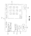
- FIG. 17 is a flow diagram illustrating one embodiment of the present invention for determining the presence or absence of a patient located in the foot zone.
- FIG. 1 shows an embodiment of a patient support 10 in accordance with the present invention.
- Patient support 10 is positioned on an exemplary bed 2 .
- Bed 2 as illustrated, is a hospital bed for use in a hospital or other health care facility, including a frame 4 , a headboard 36 , a footboard 38 , and a plurality of siderails 40 .
- Frame 4 of the exemplary bed 2 generally includes a deck 6 supported by a base 8 .
- Deck 6 includes one or more deck sections (not shown), some or all of which may be articulating sections, i.e., pivotable with respect to base 8 .
- patient support 10 is configured to be supported by deck 6 .
- Patient support 10 has an associated control unit 42 , which controls inflation and deflation of certain internal components of patient support 10 .
- Control unit 42 includes a user interface 44 , which enables caregivers and service providers to configure patient support 10 according to the needs of a particular patient. For example, support characteristics of patient support 10 may be adjusted according to the size, weight, position, or activity of the patient.
- Patient support 10 can accommodate a patient of any size, weight, height or width. It is also within the scope of the present invention to accommodate bariatric patients of up to 1000 pounds or more. To accommodate patients of varied sizes, the patient support may include a width of up to 50 inches or more.
- User interface 44 also enables patient support 10 to be adapted to different bed configurations.
- deck 6 may be a flat deck or a step deck.
- a caregiver may select the appropriate deck configuration via user interface 44 .
- An exemplary control unit 42 and user interface 44 are described in detail in U.S. Provisional Patent Application Ser. No. 60/697,708, entitled CONTROL UNIT FOR PATIENT SUPPORT, filed on Jul. 8, 2005, assigned to the assignee of the present invention, and incorporated herein by reference.
- patient support 10 has a head end 32 configured to support a patient's head and upper body region, and a foot end 34 configured to support a patient's feet and lower body region.
- Patient support 10 includes a cover 12 which defines an interior region 14 .
- interior region 14 includes a first layer 20 , a second layer 50 , and a third layer 52 .
- first layer 20 includes a three-dimensional material
- second layer 50 includes a plurality of vertically-oriented air bladders located underneath the first layer
- third layer 52 includes a plurality of pressure sensors located underneath the vertical bladders of second layer 50 , as more particularly described below.
- the vertically oriented air bladders can be cylindrical in shape where the height of a bladder is greater than the width of the bladder. Bladders of other shapes are also possible, including upstanding cylindrical bladders where the width is greater than the height.
- interior region 14 Also located within interior region 14 are a plurality of bolsters 54 , a plurality of filler portions 56 , and a pneumatic valve control box 58 .
- a fire-resistant material (not shown) may also be included in the interior region 14 .
- Patient support 10 may be coupled to deck 6 by one or more couplers 46 .
- couplers are conventional woven straps including a Velcro® brand or similar fastener. However, it is understood that other suitable couplers may be used.
- FIG. 3 Components of one embodiment of a patient support in accordance with the present invention are shown in exploded view in FIG. 3 .
- This embodiment of patient support 10 includes a top cover portion 16 and a bottom cover portion 18 .
- Top cover portion 16 and bottom cover portion 18 couple together by conventional means (such as zipper, Velcro®, snaps, buttons, or other suitable faster) to form cover 12 , which defines interior region 14 . While a plurality of layers and/or components are illustrated within interior region 14 , it will be understood by those of skill in the art that the present invention does not necessarily require all of the illustrated components.
- a first support layer 20 is located below top cover portion 16 in interior region 14 .
- Support layer includes one or more materials, structures, or fabrics suitable for supporting a patient, such as foam, inflatable bladders, or three-dimensional material. Suitable three-dimensional materials include Spacenet® and/or TytexTM-brand or similar materials.
- a second support layer including one or more bladder assemblies is located underneath the first support layer 20 .
- the illustrated embodiment of the second support layer includes first, second and third bladder assemblies, namely, a head section bladder assembly 60 , a seat section bladder assembly 62 , and a foot section bladder assembly 64 .
- first, second and third bladder assemblies namely, a head section bladder assembly 60 , a seat section bladder assembly 62 , and a foot section bladder assembly 64 .
- other embodiments include only one bladder assembly extending from head end 32 to foot end 34 , or other arrangements of multiple bladder assemblies, for example, including an additional thigh section bladder assembly.
- a pressure-sensing layer illustratively including first and second sensor pads, namely a head sensor pad 68 and a seat sensor pad 70 , is positioned underneath bladder assemblies 60 , 62 , 64 .
- Head sensor pad 68 is generally aligned underneath head section bladder assembly 60
- seat sensor pad 70 is generally aligned underneath seat section bladder assembly 62 , as shown.
- a pressure valve and transducer can be coupled to the foot section bladder assembly 64 through a fluid line to control the amount of fluid supplied to the assembly 64 as well as to measure the pressure therein.
- a turn-assist cushion 74 is located below sensor pads 68 , 70 .
- the exemplary turn-assist cushion 74 shown in FIG. 3 includes a pair of inflatable bladders. Suitable turn-assist cushions are disclosed in, for example, U.S. Pat. No. 6,499,167 to Ellis, et al., which patent is owned by the assignee of the present invention and incorporated herein by this reference. One of ordinary skill in the art will readily appreciate that turn-assist cushions 74 are not necessarily a required element of the present invention.
- a plurality of other support components 66 , 72 , 76 , 78 , 80 , 84 , 86 , 90 are also provided in the illustrated embodiment of FIG. 3 .
- One or more of these support components are provided to enable patient support 10 to be used in connection with a variety of different bed frames, in particular, a variety of bed frames having different deck configurations.
- One or more of these support components may be selectively added to or removed from patient support 10 in order to conform patient support 10 to a particular deck configuration, such as a step or recessed deck or a flat deck.
- the support components illustrated in FIG. 3 are made of foam, inflatable bladders, three-dimensional material, other suitable support material, or a combination of these.
- head filler 66 includes a plurality of foam ribs extending transversely across patient support 10 .
- Filler portion 72 includes a foam layer positioned substantially underneath the sensor pads 68 , 70 and extending transversely across the patient support 10 .
- Head bolster assembly 76 and seat bolster assembly 78 each include longitudinally-oriented inflatable bladders spaced apart by coupler plates 144 .
- first foot filler portion 80 includes a plurality of inflatable bladders extending transversely across patient support 10
- second foot filler portion 84 includes a foam member, illustratively with portions cut out to allow for retractability or for other reasons.
- Deck filler portion 90 includes a plurality of transversely-extending inflatable bladders. As illustrated, deck filler portion 90 includes two bladder sections, and is located outside of cover 12 . However, one of ordinary skill in the art will recognize that deck filler portion 90 may include one or more bladder regions, or may be located within interior region 14 , without departing from the scope of the present invention.
- a pneumatic valve box 58 and an air supply tube assembly 82 are also provided in the illustrated embodiment.
- Receptacle 88 is sized to house pneumatic valve box 58 .
- receptacle 88 is coupled to bottom cover portion 18 .
- FIGS. 4A and 4B are a simplified schematic diagram of a control system and the patient support or mattress 10 of the present invention.
- FIG. 4A illustrates the patient support 10 including the various components of patient support 10 whereas FIG. 4B illustrates the control unit 42 and the various components.
- the patient support 10 includes the sensor pad 52 which is coupled to the pneumatic valve control box 58 as previously described.
- the sensor pad 52 includes a head sensor pad 68 and a seat sensor pad 70 .
- the head sensor pad 68 is located at the head end 32 of the mattress 10 .
- the seat sensor pad 70 is located at a middle portion of the mattress 10 which is located between the head end 32 and a location of the pneumatic valve control box 58 .
- the seat sensor pad 70 is located such that a patient laying upon the mattress 10 may have its middle portion or seat portion located thereon when in a reclined state. In addition, when the head end 32 of the mattress 10 is elevated, the seat portion of the patient is located upon the seat sensor pad 70 . As previously described with respect to FIG. 3 , the head sensor pad 68 is located beneath the head section bladder assembly 60 and the seat sensor pad 70 is located beneath the seat section bladder assembly 62 . Each one of the sensors of the head sensor pad 68 or the seat sensor pad 70 is located beneath one of the upstanding cylindrical bladders or cushions.
- a head angle sensor 502 is coupled to the control box 58 where signals received from the sensor 52 may provide head angle information and pressure adjustment information for pressure in the seat bladders 62 .
- the sensor pad 52 includes individual sensors, integrated electronics, and cabling to be described later herein in more detail.
- the sensor pad 52 is coupled through the associated cabling to the pneumatic control box 58 .
- the pneumatic control box includes a multiplexer 508 coupled to the head sensor pad 68 and the seat sensor pad 70 through a signal and control line 510 .
- the multiplexer board 508 is also coupled to an air control board 512 which is in turn coupled to a first valve block 514 and a second valve block 516 .
- a communication/power line 518 is coupled to the control unit 42 of FIG. 4B .
- a ventilation supply line 520 which provides for air flow through the patient support 10 for cooling as well as removing moisture from the patient is also coupled to the control unit 42 of FIG. 4B .
- An air pressure/vacuum supply line 522 is coupled to the control unit 42 as well.
- the control unit 42 of FIG. 4B also illustrated in FIG. 1 , includes the display 44 , which displays user interface screens, and a user interface input device 524 for inputting to the control unit 42 user selectable information, such as the selection of various functions or features of the present device.
- the selections made on the user interface input device 524 control the operation of the patient support 10 , which can include selectable pressure control of various bladders within the mattress 10 , control of the deck 6 , for instance to put the bed 2 in a head elevated position, as well as displaying the current state of the mattress, deck position, and other features.
- An algorithm control board 526 is coupled to the user interface input device 524 .
- the algorithm control board 526 receives user generated input signals received through the input device 524 upon the selection of such functions by the user.
- the input device 524 can include a variety of input devices, such as pressure activated push buttons, a touch screen, as well as voice activated or other device selectable inputs.
- the algorithm control board 526 upon receipt of the various control signals through the user input device 524 controls not only the pressure regulation of the mattress 10 but also a variety of other devices which are incorporated into the control unit 42 .
- the algorithm control board 526 is coupled to a display board 528 which sends signals to the display 44 to which it is coupled.
- the display board 528 is also connected to a speaker 530 which generates audible signals which might indicate the selection of various features at the input device 24 .
- the algorithm control board 526 receives the required power from power supply 532 which includes an AC input module 534 , typically coupled to a wall outlet within a hospital room.
- the algorithm control board 526 is coupled to a compressor 536 and a blower 538 . Both the compressor 536 and the blower 538 receive control signals generated by the algorithm control board 526 .
- the compressor 536 is used to inflate the air bladders.
- the blower 538 is used for air circulation which is provided through the ventilation supply line 520 to the mattress 10 . It is, however, possible that the compressor 536 may be used to both inflate the bladders and to circulate the air within the mattress 10 .
- a pressure/vacuum switch valve 540 is coupled to the compressor 536 which is switched to provide for the application of air pressure or a vacuum to the mattress 10 .
- a muffler 541 is coupled to the valve 540 .
- a CPR button 542 is coupled to the algorithm control board 526 .
- the algorithm control board 526 , the compressor 536 , the blower 538 , and the user input device or user control module 524 are located externally to the mattress and are a part of the control unit 42 located on the footboard 38 .
- the sensors and sensor pad 52 , the pneumatic valve control box 58 , and the air control board or microprocessor 512 for controlling the valves and the sensor pad system 52 are located within the mattress 10 . It is within the present scope of the invention to locate some of these devices within different sections of the overall system, for instance, such that the algorithm control board 526 could be located within the mattress 10 or the air control board 512 could be located within the control unit 42 .
- FIG. 5 illustrates the sensor pad 52 including the head sensor pad 68 and the seat sensor pad 70 .
- Each of the pads includes a plurality of sensors configured to provide a reflected wave energy signal is described in PCT Publication WO 2004/00678A1 having a publication date of 22 Jan. 2004, the disclosure of which is incorporated by reference herein.
- the sensor pads include fiber pairs which introduce wave energy, typically light, into a compressible medium such as foam. The light introduced to the foam is scattered in a manner dependent on the force applied to the surface of the foam. The reflected or scattered light energy is detected and converted to an electrical signal indicative of the force applied to the sensor.
- Both the head sensor pad 68 and seat sensor pad 70 each include 44 individual sensors spaced throughout.
- each of individual pressure sensing elements is indicated by a number 1 through 88 .
- the sensor pad 68 and the sensor pad 70 each include and can be considered as a collection of 44 independent interface pressure sensors.
- the areas between sensors are generally not sensitive to pressure.
- the signals or data generated by the sensors indicate a pressure distribution, the data being essentially a map of the interface pressure between the bottom of the bladder assembly and the deck or frame.
- the head sensor pad 68 includes a first sensor group 550 and a second sensor group 552 .
- the first sensor group 550 is located in an upper left quadrant of the sensor pad 52 whereas the second sensor group 552 is in an upper right quadrant of the sensor pad 52 .
- Each of the individual sensor groups 550 and 552 include 22 sensors, the location of which is indicated and identified by a number. For instance, the first sensor group 550 includes sensors 1 through 22 and the second sensor group 552 includes sensors 23 through 44 .
- the numerical order of the individual sensors indicates the sequence in which the information from each of these sensors is accessed by the multiplexer board 508 .
- the seat sensor pad 70 includes a third sensor group 554 and a fourth sensor group 556 configured to be substantially the same as the first sensor group 550 and the second sensor group 552 as previously described.
- Each of the sensor groups includes 22 sensors which have numbers indicating the sequence in which the signal information is accessed or derived therefrom.
- Each of the sensor groups 550 , 552 , 554 , and 556 include an optical system device 560 , 562 , 564 , and 566 respectively. Each of these devices includes a cable for connection to the pneumatic valve control box 58 . Since each of the first sensor group 550 , 552 , 554 , and 556 are substantially identical in construction, the optical system device 560 will be described and its description will apply to the remaining optical system devices 562 , 564 and 566 .
- the optical system device 560 is an opto-electronics interface board including software embedded on a micro controller integrated with an opto-board and the sensor pad itself.
- the embedded software of the microprocessor is typically referred to as “firmware”.
- each of the sensors includes fiber optic cable which is coupled to the opto-electric board.
- Two light emitting diodes supply light to each of the individual sensors and a single photo diode array reads the optical inputs of all 22 sensors within a sensor group.
- An erasable programmable read only memory and a serial interface driver for communication are included.
- the primary purpose of the optical system device is to acquire the information sensed by each of the individual sensors which result from the reflected light which has been passed through the fiber optic cable to the individual sensor.
- Algorithms within the embedded microprocessor are used to linearize the data sensed by the sensors.
- the sensor data and diagnostic data are made available to the multiplexer 508 through RS-232 ports. Data is transmitted though the network 578 , which may be a controller area network (CAN) bus, to the algorithm control unit 526 .
- CAN controller area network
- FIG. 6 illustrates an overall system architecture 570 of the present invention.
- the multiplexer board 508 also known as a sensor communication hub, is coupled to the head zone sensor 68 and the seat zone sensor 70 .
- the multiplexer 508 as well as the optical system devices includes a number of sensory algorithms to be described later herein.
- the algorithm control unit 526 which includes a second set of sensory algorithms 574 and control algorithms 576 .
- the output of the multiplexer 508 and the algorithm control unit 526 are coupled to a network 578 which is also coupled to the air control unit 512 and the LCD display unit 44 .
- the network 578 includes interface hardware, also known as a communication hub.
- the network 578 acts as the communication bus for the various hardware, software, and firmware control devices.
- the multiplexer 508 includes the sensory algorithms 572 .
- the algorithm control unit 526 also includes sensory algorithms which may include algorithms for providing pressure relief, for providing a motion metric, for providing weight estimation, and for providing information to a LCD module which includes a calculation of statistics model.
- FIG. 7 illustrates a block diagram of a control system 580 incorporating the LCD display unit 44 , the air control board 512 , the communication hub or network 508 , and the algorithm control unit 526 .
- the communication hub 508 which receives sensor data from the head zone sensor 68 and the seat zone sensor 70 is coupled to both the LCD display unit 44 and the algorithm control unit 526 through a first sensor data line 582 and a second sensor data line 584 respectively.
- the algorithm control unit 526 includes sensory algorithms 574 and control algorithms 576 .
- the algorithm control unit 526 includes a first output line 586 coupled to the LCD display unit 44 for transmitting patient position monitor status, a second control line 588 for communicating movement status, and a third control line 590 for communicating the status of the algorithm control unit.
- the algorithm control unit 526 includes a fourth output line 592 which transmits the zone pressure set points for each of the head, seat and foot zones to the air control board 512 to which the line 592 is coupled.
- the air control board 512 which includes the pressure sensors previously described, sends control pressure zone feedback signals through a line 594 back to the algorithm control unit 526 .
- a fifth control line 595 coupled to the algorithm control unit 526 and to the LCD display unit 44 transmits status information related to the pressure offsets being applied to the optimized pressures determined by the algorithm control unit 526 .
- the control line 595 while illustrated as a separate control line may be included with the third control line 590 if desired.
- pressure setpoints of the head, seat, and foot zones, based on patient weight without being optimized may be transmitted to the display unit 44 .
- the LCD display unit 44 through the user input interface device 524 also sends control signals to the algorithm control unit 526 through a control line 596 which includes signals such as various mode command signals as well as bed type command signals for adjusting the frame or deck of the bed. These signals include signals indicating the offset to be applied to the offset pressure when in the comfort control mode as well as signals inducting the selection of the comfort control mode and the manual mode.
- the present invention includes sensory algorithms as well as control algorithms.
- the sensory algorithms are provided in firmware located within the multiplexer 508 and the algorithm control unit 526 .
- Sensory algorithms include the following: bottom out detection, where a portion of the subject is supported by the bed frame as opposed to the surface, bed exit detection, sitting on the side of a bed detection, detection of a patient lying on the edge of the surface, detecting a lack of patient movement on the surface over a period of time, providing patient position monitoring by distinguishing between the following six positions left lying, left sitting, center lying, center sitting, right lying, right sitting, and measuring patient weight within plus or minus 20% within the bed and the flat position.
- the control system algorithms which are located in the control system algorithm firmware 576 optimize pressure reduction by dynamic load distribution adjustment of the surface air bladders of the mattress 10 located above the head sensor pad 68 and the seats sensor pad 70 .
- FIG. 8 is a flow chart illustrating a method of determining a pressure for the patient support of the present invention in a pressure adjustment mode.
- This mode is also called firmness override mode or comfort control mode.
- the present invention provides for pressure relief within the air bladders by monitoring the air pressure in the bladders and controlling that air pressure through the detection of the force or pressure transmitted through the air bladders to the sensors located therebeneath.
- the present invention includes an offset pressure which controls the adjustment of pressure around an optimized air pressure which is determined according to the described method. Based on the assumption that the optimum air pressure is the pressure just prior to bottoming out, the bottoming out condition may be used as a signal that the optimum pressure has been reached.
- the optimum pressure may be considered to be the pressure just prior to bottoming out, on occasion a patient may desire to have the pressure adjusted to a value different than the value of the determined optimized pressure.
- the optimum pressure may not be preferred by an individual patient or caregiver and consequently the present invention may be used to adjust the air pressure above or below the optimum air pressure.
- a comfort adjust or pressure adjustment mode is selected by the caregiver. Selection of this mode is further described with the user interface for the discussion of FIGS. 10-15 to be described later.
- the pressure setting is adjusted.
- the head zone bladders, seat zone bladders, and foot zone bladders may be adjusted.
- the adjustment of the pressure setting for each of these zones is an incremental or decremental pressure offset around a determined optimized pressure. Once the amount of pressure adjustment or offset has been selected by the caregiver at step 602 , an optimal pressure is determined.
- the bladders are initially filled to a high pressure at step 604 of FIG. 8 .
- the bladders may be filled to 25 inches of water.
- the mass of the patient is calculated according to a mass or weight algorithm as is known by those skilled in the art.
- the pressure within the bladders is lowered by fixed increments at step 606 of FIG. 8 .
- the sensors of the sensor pads 68 and 70 are accessed according to the sequences previously shown in FIG. 5 .
- the data or information provided by 22 of the sensors within each of the sensor groups is read or provided approximately every one quarter of a second.
- the information from the first, second, third and fourth sensor groups 550 , 552 , 554 , and 556 are provided approximately every one second. This information is used to compute the bottoming out indicators at step 608 .
- the bottoming out indicators are derived from the pressure distribution data derived from the sensors from each of the sensor pads 68 and 70 .
- the bottom-out indicators are used to determine a bottoming-out trend.
- Such indicators may include:
- the pressure optimization algorithm may use a distributed standard deviation of the data to provide an indicator which corresponds to a pressure within each of the head and seat bladder sections.
- only the seat bladder section is used to provide for the optimization algorithm and the head section bladder pressure is determined as a percentage of the seat bladder section pressure determined.
- the air pressure is continually reduced at step 606 as long as the advance notice of bottoming out at decision step 610 is not indicated. If, however, the advance notice of bottoming out does occur as determined at decision step 610 , then the preferred or optimum value of pressure is reached at step 612 . Once the optimum pressure is reached at step 612 , then the pressure adjustment or offset is applied to that optimum value at step 614 .
- the adjust pressure algorithm then sends a signal to the air pressure controller or valves of the air control board 512 to maintain the pressure within the head, seat and/or foot zone.
- the pressure or forces transmitted through each of the zone bladders is continuously monitored and used to adjust the pressure within the bladders.
- the pressure is maintained in the comfort adjust mode by maintaining the optimum pressure determined plus the pressure adjustment offset which adjusts the optimum pressure above or below the determined optimum pressure.
- the pressure or forces transmitted through the zones are continuously monitored at this step. If, however, the pressure is adjusted through the user interface, or an elapsed time period has occurred over which no movement has taken place, or there is actual movement as determined at Step 618 , then the system reinitializes itself and returns to step 604 .
- the algorithm pressurizes the bladder to a high air pressure and reduces that air pressure by a fixed increment to determine the trend toward bottoming out.
- the pressure adjustment above or below optimum is applied to the determined optimum pressure and is maintained at step 616 . If there is no pressure adjustment by a caregiver or the elapsed time period has not occurred or if there is no movement, then the optimum pressure including the pressure adjustment offset is maintained at step 616 .
- FIG. 9 illustrates a state transition diagram for a pressure relief state machine 746 .
- the bottoming-out indicators provide advance notice of bottoming-out. Based on the assumption that the optimum air pressure is the pressure just prior to bottoming-out, this advance notification is used as a signal that the optimum or preferred pressure has been reached. As previously described, air pressure is reduced in increments. After each increment the bottoming-out indicators may be computed. At the time that the bottoming-out indicators provide advance notice, then the air pressure maintained is that at that setting and the optimum or preferred pressure relief is achieved.
- the curved arrows indicate the allowable transitions between states.
- the conditions that precipitate a transition from one state to another are labeled on each arrow. In some cases, the reasons are based on a count of the number of indicators meeting a certain condition (eg. “>2 indicators decreasing”). It is to be understood that conditions may be replaced by comparing a single indicator (or weighted sum of indicators) against a suitable threshold.
- the air is reduced at a reduce air state 750 . If it is determined that the indicators are decreasing, the system continues to reduce the air in the mattress bladders. If, however, it is determined that more than two indicators are increasing, the system enters a bottoming-out recovery state 752 . The system remains in the bottoming-out recovery state if the indicators are not consistent. If, however, the indicators are increasing, then the system returns to the reduce air state 750 . If, on the other hand, all indicators are decreasing, then the system enters an increase air state 754 where the air within the bladder is increased. The system remains in the increase air state 754 if all indicators are decreasing.
- the system leaves the increase air state 754 and returns to the bottoming-out recovery state 752 . If one indicator increases, then the system moves to the hold state 756 where the air pressure within the mattresses is maintained for the optimum or preferred pressure relief. If there are no changes to the indicators while in the hold state 756 , the system remains in the optimal pressure mode. If, however, more than two indicators have increased while in the hold state 756 , the system returns to the bottoming-out recovery state 752 as previously described. While in the hold state 756 , a timer is set which enables the system to check for an optimum state at check optimum state 758 after the time out has elapsed.
- the system When in the check optimum state 758 , if one or two indicators have increased, the system returns to the reduce air state 750 where the air in the bladders is reduced. If the optimum state is detected while in the reduced air state 750 , the system moves to the check optimum state 758 .
- a timer may also be set while in the reduce air state 750 whereupon at the end of the elapsed time the system returns to the hold pressure state 756 .
- the automatic control system When the bed is empty, the automatic control system is in the “Bed Empty” state. In this state, the control system sets the air pressure set-point to a value sufficient to fully inflate the air bladder.
- the automatic control system instructs the air regulator to reduce the air pressure by some increment. After a period of time, the indicators are computed. If the indicators have reduced, then the automatic control system remains in the “reduce air” state and initiates another decrement to the air pressure. If an indicator or two are found to have increased, then it means that the bottoming-out trend has started, and so the automatic control system switches to the “hold” state.
- the automatic control system instructs the air regulator to maintain the air pressure at the value it was when the state was entered.
- the indicators are computed. If there is no significant change in indicators, then the automatic control system remains in the “hold” state. If an indicator increases while in the “hold” state, it may be indicative of the occupant moving. In that case it is necessary to conduct a test to determine if the air pressure presently being maintained is optimal. This test is automatically conducted by switching to the “check optimum” state.
- the automatic control system instructs the air pressure regulator to increment the air pressure by some interval.
- the indicators are computed. If the indicators decreased, it indicates that another increment in air pressure is required, so the system switches to the “increase air” state (which is subsequently described). As previously stated, the indicators were chosen so that minimum values are reached at or about the lowest air pressure prior to bottoming-out. Therefore, if the indicators decrease with increasing air pressure, then it indicates that the air pressure is still too low—further increasing the air pressure is likely to further reduce the indicators. If, on the other hand, the indicators generally increase after the increment in air pressure, then the opposite is true: the air pressure is now higher than optimum, and the system switches into the “reduce air” state.
- the automatic control system instructs the air regulator to increase the air pressure by some increment. After a period of time, the indicators are computed. If the indicators have reduced, then the automatic control system remains in the “increase air” state and initiates another increment to the air pressure. If an indicator or two are found to have increased, then it means that the bottoming-out trend has been reverted, and so the automatic control system switches to the “hold” state.
- FIG. 10 is a screen display 800 displayed on the user interface 44 when the patient support is in the automatic pressure relief or optimized pressure mode.
- This mode is the default mode when the mattress system is initially turned on.
- the screen display 800 includes a mode identifying area or portion 802 where the current mode is displayed. As illustrated in section 802 , the mode currently being displayed is the automatic pressure relief mode.
- a menu button 804 is included to select various features of the present apparatus to be described herein.
- a middle portion 806 of the screen display 800 may be used to display the current status of the patient support. For instance, as illustrated, the head of bed is elevated at less than 30 degrees and a patient 808 is diagrammatically illustrated as laying on a surface 810 .
- a bottom portion 809 illustrates a number of selectable user interface buttons or inputs, which may include touch screen buttons or electrical contact buttons.
- the included user interface selector buttons are a key button 811 , a turn assist button which includes a left turn assist button 812 and a right turn assist button 814 , and a maximum (max) inflate button 816 .
- FIG. 11 illustrates the screen display 800 where the menu button 804 has been selected to display a pull down menu 818 .
- the pull down menu 818 includes a number of selector buttons for choosing from a variety of functions.
- the pull down menu 818 includes a selector 820 for alarm settings, a selector 822 for selecting the motion monitor which has been described in U.S. patent application Ser. No.
- a user interface screen 832 of FIG. 12 is displayed.
- the selected mode of comfort adjust is displayed.
- an off button 838 to turn off comfort adjust mode
- a comfort adjust button 839 which includes a schematic drawing of a patient on a surface.
- the language “For optimal therapy, comfort adjust should remain off” is displayed.
- the portion 840 indicates that the comfort adjust has not yet been selected since the user interface selector buttons 841 are illustrated as being in dotted outline.
- display 841 of the portion 840 includes a lighter or phantom image where the caregiver may not select the various buttons displayed which are lightly shown. When selectable, the displayed images are shown in a darker or full image.
- the screen display 832 includes a help button 842 for providing information to a caregiver when help is needed as well as a done button 844 which may be selected if the caregiver decides that the comfort adjust mode or function is not preferred at this time.
- the caregiver selects the comfort adjust button 839 of FIG. 12 .
- a warning screen 840 appears, indicating that the therapy is not optimized or is not in an optimal condition when the comfort adjust is active.
- the caregiver selects the OK button 846 to enter the comfort adjust function. If, however, the caregiver decides that the comfort adjust therapy is not desired, the caregiver selects the cancel button whereupon the screen display returns to the screen display 800 of FIG. 10 .
- FIG. 14 illustrates a comfort adjust screen display 850 of the present invention.
- the screen display 850 includes a mode identifying portion or area 852 indicating that the comfort adjust function has been selected. While in the comfort adjust function, a portion 854 indicates that the mattress is currently in the comfort adjust mode and not in the optimal therapy mode. A button 855 is provided for turning the comfort adjust off.
- a bottom portion 856 of the screen display 850 includes a selector portion 858 as well as patient interface portion 859 .
- the portion 858 includes a plurality of adjustment buttons for adjusting an offset pressure around the optimum pressure as previously described.
- an up/down selector 860 includes an up button 862 and a down button 864 for adjusting the offset to a head portion 866 of the mattress.
- a seat adjustment portion 868 includes an up button 870 and a down button 872 .
- the seat portion pressure may be adjusted with the up and down buttons to select the offset from optimal for the seat portion 874 .
- a foot adjustment selector 876 adjusts a seat portion 878 which includes an up button 880 and a down button 882 . In this way, a caregiver may adjust each of the sections to a preferred pressure according to the patient's or caregiver's wishes.
- the screen display 850 also includes the previously described help button 842 and the done button 844 .
- FIG. 15 illustrates a screen display 890 of the present invention once the comfort adjust mode has been selected and the offset pressures selected.
- a mode identifying portion 892 indicates that the support system is in the comfort adjust mode and that the therapy is less than optimal while the comfort adjust is active.
- a portion 894 of the display 890 illustrates the patient 808 lying upon the support surface 810 . While in the comfort adjust mode, the support surface 818 indicates the amount of pressure offset in a head zone 896 , a seat zone 898 and a foot zone 900 . Any zone may be adjusted. It is within the scope of the present invention to provide for the adjustment of any one zone, any two zones, or all three zones.
- Each of the zones 896 , 898 and 900 include one or more illustrated horizontal bars to provide an indication of the amount of change which has been made to the automatic pressure relief mode.
- the full range of adjustment or offset is 2 inches of water. Consequently with 4 bars of adjustment, each single bar provides an adjustment of one-half inch of water. It is within the scope of the present invention to include other ranges of offset and other numbers of bars. The amount of adjustment corresponding to a single bar may be other than one-half inch of water.
- the screen display 890 also includes the previously described key button 810 , left turn assist button 812 , right turn assist button 814 and max inflate button 816 . Consequently, while in the comfort adjust mode, the turn assist functions are available as well as the maximum inflate function.
- a manual mode display screen 910 is displayed for selecting a manual mode.
- the menu button 804 of FIG. 11 is selected to display the pull down menu 818 .
- the in-service button 830 the manual mode may be selected through another pull-down menu (not shown).
- the in-service features are only available to a technician.
- the service technician may select the manual mode by selecting the manual mode on/off button 912 . If the manual mode is selected, the automatic pressure relief function as well as the comfort adjust functions are turned off, such that the mattress pressures are determined according to patient weight only. Suitable mattress pressure corresponding to patient weight are stored in a look-up table as is understood by those skilled in the art.
- the system when the manual mode defaults to a patient weight of 200 lbs., is illustrated at weight line 914 .
- the technician may, however, select another patient weight, for instance, from 70 to 400 pounds. Other weights are within the scope of the invention.
- the technician selects a weight by entering the appropriate value with a keypad 916 which includes numeric buttons and a clear button. Once the weight is entered, the selected weight appears in the weight display 918 . If the technician is satisfied with the entered weight, it may be saved by pressing the save weight button 920 . Once weight is entered, the system may generate the appropriate pressure(s) according to the look-up table. Once the weight is entered, an exit button 922 may be pressed to return to the main service screen.
- the display 910 also includes the mattress serial number, the current date, and an identifying portion 924 to indicate bed type, mattress mode, and a service phone number. The pressures which have been set based on the entered weight are maintained until changed by the technician or other individual.
- FIG. 17 is a flow diagram illustrating one embodiment of the present invention for determining the presence or absence of a patient located on the foot zone bladders in the foot zone.
- the interface between the patient and the mattress should be stable and supportive.
- the mattress permits the patient to sit without excess movement of the mattress underneath.
- the position of the patient should be sufficiently stable to evenly support the patient so that tipping is prevented. It is preferred that even support occurs whether the patient is sitting entirely in the foot zone or if the patient is straddling the boundary of the foot zone and the seat zone.
- the algorithms detect the presence or absence of the patient in the head, seat, or foot zone, and the adjusts the air pressures accordingly.
- Patient location may be determined by the sensor pads, as described herein, or by the air pressure of the foot zone determined by the pressure valve/transducer coupled to the foot zone bladder.
- the foot zone pressure is monitored by the pressure transducer and is stored over time in a memory device or buffer of the control system. This pressure value is continually updated and past values are stored for use in the algorithm.
- the change in pressure is determined over a predetermined period of time, for instance, a period of 5 seconds. Other periods or time are within the scope of the present invention.
- the change in pressure over the change in time is denoted as ⁇ P/ ⁇ T.
- the ⁇ P/ ⁇ T is compared to two predetermined values, the result of which indicates that motion has occurred. For instance, if ⁇ P/ ⁇ T is greater than a first predetermined value or if ⁇ P/ ⁇ T is less than a second predetermined value, then motion is detected at step 1004 of FIG. 17 . An increase in pressure resulting from a patient ingress would provide a positive value of ⁇ P/ ⁇ T and if this value is greater than the first predetermined value, then motion is detected at step 1004 .
- a decrease in pressure resulting from a patient egress would provide a negative value of ⁇ P/ ⁇ T and if this value is less than the second predetermined value, then motion is also detected at step 1004 If, however, motion is not detected, then the algorithm continues to calculate ⁇ P/ ⁇ T.
- the foot zone pressure occurring prior to the detected motion is identified and is stored for later use. Once this pressure value is stored, the valves supplying air to the foot zone are locked in a closed position at step 1008 , thereby substantially preventing the foot zone bladders from being controlled to a different pressure.
- the algorithm determines whether there is stability or little change to the foot zone pressure. This determination is made by calculating the change in pressure to the foot zone over a period of time. If for instance, the change is less than one-half inch of water over a period of 5 seconds, then the algorithm determines that motion has ceased at step 1010 . If the pressure has not stabilized, then the valves remain locked at step 1008 . If, however, the motion has ceased, the foot zone pressure occurring after the motion has ceased is stored at step 1012 .
- the pressure value is stored, at step 1014 .
- This value of pressure is compared to the previously stored value of pressure which was determined prior to the motion being detected. Based upon this comparison, the pressures are set in the foot zone and the seat zone at step 1016 .
- the pressures set in the foot zone and the seat zone at step 1016 are based on a determination of whether the pressure in the foot zone went up or down when compared to the previously stored value of the foot zone pressure occurring prior to the detected motion. If the pressure increased by a predetermined amount, for instance 5 inches of water, then the patient is found to be sitting or partially sitting in the foot zone. If, however, the air pressure decreased by a predetermined amount, the patient is found to be no longer sitting in the foot zone.
- the seat zone pressure is set to eighty percent of the foot zone pressure. If, however, the seat zone pressure is not less than eighty percent of the foot zone pressure, the foot zone pressure is set to one-hundred twenty-five percent of the seat zone pressure.
- the bladders are set to fixed predetermined pressures.
- the seat zone pressure can be set to twenty-five inches of water and the foot zone pressure can be set to thirty inches of water.
Abstract
Description
-
- (a) The sum of outputs of sensors over a “high pressure threshold.” For this indicator, a threshold is set, and the amount by which the sensors exceed this threshold is accumulated. The high-pressure threshold may be fixed, or preferably, it may be computed from time to time in proportion to the average sensor output. It has been found that it is preferable to set the high-pressure threshold in the range of 1.2 to 3.0 times the average of all sensor outputs.
- (b) The area not providing support, as measured by the number of sensors below a “support threshold”. The “area not providing support” decreases when the support area increases. The support threshold may be fixed, or preferably, the support threshold may be computed from time to time in proportion to the average sensor output. It has been found that it is preferable to set the high-pressure threshold in the range of 0.1 to 0.7 times the average of all sensor outputs.
- (c) The number of sensors over a high-pressure threshold. Similar to the indicator described in (a) above, a high-pressure threshold is set, and the number of sensors that exceed that high-pressure threshold is counted.
- (d) The maximum output reported by any given sensor.
- (e) The average value of the three sensors reporting the highest outputs.
- (f) The standard deviation of all of the sensor outputs. This is calculated in accordance with the formula: standard deviation equals the square root of the sum of squared differences between the sensor output and the mean sensor output, divided by the number sensors minus one.
- (g) The high-side deviation of sensor outputs. This indicator calculated in a similar manner to the standard deviation. In this case, however, only those sensor outputs that exceed the mean sensor output are used in the computation.
- (h) The changes in the above indicators as a ratio to the change in bladder air pressure.
Claims (30)
Priority Applications (1)
| Application Number | Priority Date | Filing Date | Title |
|---|---|---|---|
| US11/994,477 US8844079B2 (en) | 2005-07-08 | 2006-07-07 | Pressure control for a hospital bed |
Applications Claiming Priority (3)
| Application Number | Priority Date | Filing Date | Title |
|---|---|---|---|
| US69774805P | 2005-07-08 | 2005-07-08 | |
| US11/994,477 US8844079B2 (en) | 2005-07-08 | 2006-07-07 | Pressure control for a hospital bed |
| PCT/US2006/026787 WO2007008830A2 (en) | 2005-07-08 | 2006-07-07 | Pressure control for a hospital bed |
Publications (2)
| Publication Number | Publication Date |
|---|---|
| US20090144909A1 US20090144909A1 (en) | 2009-06-11 |
| US8844079B2 true US8844079B2 (en) | 2014-09-30 |
Family
ID=37637851
Family Applications (1)
| Application Number | Title | Priority Date | Filing Date |
|---|---|---|---|
| US11/994,477 Active 2029-09-24 US8844079B2 (en) | 2005-07-08 | 2006-07-07 | Pressure control for a hospital bed |
Country Status (5)
| Country | Link |
|---|---|
| US (1) | US8844079B2 (en) |
| EP (1) | EP1906793B1 (en) |
| JP (1) | JP5537806B2 (en) |
| AU (1) | AU2006268287B2 (en) |
| WO (1) | WO2007008830A2 (en) |
Cited By (26)
| Publication number | Priority date | Publication date | Assignee | Title |
|---|---|---|---|---|
| US20160153511A1 (en) * | 2013-07-09 | 2016-06-02 | Simon Dickinson | Improvements to structure to resist impact |
| WO2017194037A1 (en) | 2016-05-12 | 2017-11-16 | Linet Spol. S R.O. | A mattress with automatic pressure optimization |
| US10045715B2 (en) | 2015-04-27 | 2018-08-14 | Hill-Rom Services, Inc. | Self-compensating bed scale system for removable components |
| US10054479B2 (en) | 2015-05-05 | 2018-08-21 | Hill-Rom Services, Inc. | Bed with automatic weight offset detection and modification |
| US20200037779A1 (en) * | 2018-07-31 | 2020-02-06 | Levy Zur | Area support surface seating system |
| USD877915S1 (en) | 2018-09-28 | 2020-03-10 | Stryker Corporation | Crib assembly |
| USD879966S1 (en) | 2018-09-28 | 2020-03-31 | Stryker Corporation | Crib assembly |
| USD888962S1 (en) | 2018-09-28 | 2020-06-30 | Stryker Corporation | Cover assembly for a patient support |
| USD888964S1 (en) | 2018-09-28 | 2020-06-30 | Stryker Corporation | Crib assembly for a patient support |
| USD888963S1 (en) | 2018-09-28 | 2020-06-30 | Stryker Corporation | Cover assembly for a patient support |
| USD890914S1 (en) | 2018-10-31 | 2020-07-21 | Stryker Corporation | Pump |
| USD892159S1 (en) | 2018-10-31 | 2020-08-04 | Stryker Corporation | Display screen with animated graphical user interface |
| USD893543S1 (en) | 2018-10-31 | 2020-08-18 | Stryker Corporation | Display screen with graphical user interface |
| USD894223S1 (en) | 2018-10-31 | 2020-08-25 | Stryker Corporation | Display screen with animated graphical user interface |
| USD894226S1 (en) | 2018-10-31 | 2020-08-25 | Stryker Corporation | Display screen or portion thereof with graphical user interface |
| USD894957S1 (en) | 2018-10-31 | 2020-09-01 | Stryker Corporation | Display screen or portion thereof with graphical user interface |
| USD894956S1 (en) | 2018-10-31 | 2020-09-01 | Stryker Corporation | Display screen or portion thereof with graphical user interface |
| USD901940S1 (en) | 2018-09-28 | 2020-11-17 | Stryker Corporation | Patient support |
| US11173085B2 (en) | 2017-12-28 | 2021-11-16 | Stryker Corporation | Mattress cover for a mattress providing rotation therapy to a patient |
| US11246775B2 (en) | 2017-12-28 | 2022-02-15 | Stryker Corporation | Patient turning device for a patient support apparatus |
| US11253079B1 (en) | 2018-03-26 | 2022-02-22 | Dp Technologies, Inc. | Multi-zone adjustable bed with smart adjustment mechanism |
| USD950588S1 (en) * | 2019-02-18 | 2022-05-03 | Samsung Electronics Co., Ltd. | Display screen or portion thereof with graphical user interface |
| US11439248B2 (en) | 2018-12-14 | 2022-09-13 | Sleep Technologies, Llc | Adjustable sleeping system with massage function |
| US20220326099A1 (en) * | 2021-04-07 | 2022-10-13 | Nano And Advanced Materials Institute Limited | Textile pressure sensor array and pressure distribution mapping system |
| USD977109S1 (en) | 2018-09-28 | 2023-01-31 | Stryker Corporation | Crib assembly for a patient support |
| USD992946S1 (en) * | 2021-05-07 | 2023-07-25 | Tanya Ann Wiese | ICU bed extension for proning |
Families Citing this family (38)
| Publication number | Priority date | Publication date | Assignee | Title |
|---|---|---|---|---|
| CN101528830A (en) | 2006-07-10 | 2009-09-09 | 麦德医像公司 | Super elastic epoxy hydrogel |
| US10864137B2 (en) | 2006-09-14 | 2020-12-15 | Ascion, Llc | System and method of an adjustable bed with a vibration motor |
| US7321811B1 (en) | 2006-09-14 | 2008-01-22 | Rawls-Meehan Martin B | Methods and systems of adjustable bed position control |
| US8926535B2 (en) | 2006-09-14 | 2015-01-06 | Martin B. Rawls-Meehan | Adjustable bed position control |
| US10064784B2 (en) | 2006-09-14 | 2018-09-04 | Martin B. Rawls-Meehan | System and method of an adjustable bed with a vibration motor |
| US8572778B2 (en) | 2007-03-30 | 2013-11-05 | Hill-Rom Services, Inc. | User interface for hospital bed |
| AU2008316981A1 (en) * | 2007-10-22 | 2009-04-30 | Martin B. Rawls-Meehan | Adjustable bed position control |
| EP2245678A1 (en) * | 2008-02-19 | 2010-11-03 | Medipacs, Inc. | Therapeutic pressure system |
| US9756959B2 (en) | 2008-11-26 | 2017-09-12 | Dreamwell, Ltd. | Systems and methods for mattress assemblies with attached customer assistance sensory devices |
| US20100268399A1 (en) * | 2009-04-15 | 2010-10-21 | Chen-Hung Tsai | Method for operating air mattress controller and structure thereof |
| US8677536B2 (en) * | 2009-11-18 | 2014-03-25 | Hill-Rom Services, Inc. | Method and apparatus for sensing foot retraction in a mattress replacement system |
| US8260475B2 (en) * | 2009-11-19 | 2012-09-04 | Hill-Rom Services, Inc. | Constant low-flow air source control system and method |
| JP5616076B2 (en) | 2010-02-05 | 2014-10-29 | パラマウントベッド株式会社 | Air mattress |
| US8650682B2 (en) | 2010-03-02 | 2014-02-18 | Hill-Rom Services, Inc. | Multifunctional display for hospital bed |
| US9345335B2 (en) | 2010-09-27 | 2016-05-24 | Gualtiero G. Giori | Pressure control and feedback system for an adjustable foam support apparatus |
| US9492341B2 (en) | 2010-10-08 | 2016-11-15 | Hill-Rom Services, Inc. | Hospital bed with graphical user interface having advanced functionality |
| US9707142B2 (en) | 2011-03-03 | 2017-07-18 | Hill-Rom Services, Inc. | Occupant support and method for positioning an occupant on the occupant support |
| US8973186B2 (en) * | 2011-12-08 | 2015-03-10 | Hill-Rom Services, Inc. | Optimization of the operation of a patient-support apparatus based on patient response |
| CA2906274A1 (en) | 2012-03-14 | 2013-09-19 | Medipacs, Inc. | Smart polymer materials with excess reactive molecules |
| US11039962B2 (en) | 2012-04-02 | 2021-06-22 | TurnCare, Inc. | Non-invasive pressure-mitigation apparatuses for improving blood flow and associated systems and methods |
| US20130255699A1 (en) * | 2012-04-02 | 2013-10-03 | TurnCare, Inc. | Patient-orienting alternating pressure decubitus prevention support apparatus |
| US11071666B2 (en) * | 2012-05-22 | 2021-07-27 | Hill-Rom Services, Inc. | Systems, methods, and devices for treatment of sleep disorders |
| US9228885B2 (en) | 2012-06-21 | 2016-01-05 | Hill-Rom Services, Inc. | Patient support systems and methods of use |
| US20140026326A1 (en) * | 2012-07-25 | 2014-01-30 | Richard N. Codos | Pressure adjustable platform system |
| US9468307B2 (en) | 2012-09-05 | 2016-10-18 | Stryker Corporation | Inflatable mattress and control methods |
| CA2942274A1 (en) * | 2014-03-13 | 2015-09-17 | Hillenbrand Management Company Llc | Patient monitoring and repositioning system and method |
| US9504620B2 (en) * | 2014-07-23 | 2016-11-29 | American Sterilizer Company | Method of controlling a pressurized mattress system for a support structure |
| PT107863A (en) * | 2014-08-29 | 2016-02-29 | Freedom To Enjoy Lda | CONTACT PRESSURE CONTROL SYSTEM BETWEEN THE BODY AND CONTACT SURFACES OF THE SAME. |
| US10292881B2 (en) * | 2014-10-31 | 2019-05-21 | Hill-Rom Services, Inc. | Dynamic apnea therapy surface |
| CN111369764A (en) * | 2015-05-15 | 2020-07-03 | J·布拉施有限公司 | System and method for monitoring people by simulating multi-region pressure sensitive pad |
| JP6730327B2 (en) * | 2015-05-29 | 2020-07-29 | ヒル−ロム サービシズ,インコーポレイテッド | Patient support device |
| US10489661B1 (en) | 2016-03-08 | 2019-11-26 | Ocuvera LLC | Medical environment monitoring system |
| JP6847218B2 (en) * | 2016-11-28 | 2021-03-24 | バーブ サージカル インコーポレイテッドVerb Surgical Inc. | Robotic surgical system to reduce unwanted vibrations |
| US10600204B1 (en) | 2016-12-28 | 2020-03-24 | Ocuvera | Medical environment bedsore detection and prevention system |
| US20190015702A1 (en) * | 2017-07-17 | 2019-01-17 | Aurora Flight Sciences Corporation | Dynamic Load Sensor for Microgravity |
| US11163270B2 (en) * | 2019-07-10 | 2021-11-02 | Lear Corporation | Vehicle occupant data collection and processing with artificial intelligence |
| KR20210124680A (en) * | 2020-04-07 | 2021-10-15 | 엘지전자 주식회사 | Control method of bed |
| US11376179B1 (en) * | 2021-07-08 | 2022-07-05 | Foshan Hongfeng Medical Technology Co., Ltd | Multifunctional nursing mattress |
Citations (115)
| Publication number | Priority date | Publication date | Assignee | Title |
|---|---|---|---|---|
| US779576A (en) | 1903-09-11 | 1905-01-10 | Benjamin F Berryman | Mattress. |
| GB159299A (en) | 1919-11-22 | 1921-02-22 | Charles Reginald Stone | Air- and water-mattresses and the like |
| US3303518A (en) | 1962-03-05 | 1967-02-14 | Ingram George | Inflatable mattresses, pillows and cushions |
| US3772717A (en) | 1971-02-05 | 1973-11-20 | Y Yuen | Inflatable mattresses and cushions |
| US3978530A (en) | 1975-11-21 | 1976-09-07 | Amarantos John G | Air inflatable bed-like device with adjustable back support |
| US4120061A (en) * | 1977-10-13 | 1978-10-17 | Clark Harold E | Pneumatic mattress with valved cylinders of variable diameter |
| GB2092439A (en) | 1981-01-09 | 1982-08-18 | Aisin Seiki | Inflatable supports |
| US4477935A (en) | 1982-01-08 | 1984-10-23 | Griffin Gordon D | Mattress support system |
| US4483029A (en) | 1981-08-10 | 1984-11-20 | Support Systems International, Inc. | Fluidized supporting apparatus |
| US4525885A (en) | 1980-02-26 | 1985-07-02 | Mediscus Products Limited | Support appliance for mounting on a standard hospital bed |
| US4527298A (en) | 1982-03-18 | 1985-07-09 | Moulton Lee A | Electro pneumatic bed |
| US4541135A (en) | 1984-04-16 | 1985-09-17 | Victor Karpov | Air mattress |
| US4542547A (en) | 1982-12-15 | 1985-09-24 | Hiroshi Muroi | Pnuematic mat with sensing means |
| US4637083A (en) | 1985-03-13 | 1987-01-20 | Support Systems International, Inc. | Fluidized patient support apparatus |
| US4638519A (en) | 1985-04-04 | 1987-01-27 | Air Plus, Inc. | Fluidized hospital bed |
| GB2199803A (en) | 1987-01-20 | 1988-07-20 | Sanwa Shutter Corp | Elevation bed |
| US4797962A (en) | 1986-11-05 | 1989-01-17 | Air Plus, Inc. | Closed loop feedback air supply for air support beds |
| US4825486A (en) | 1987-06-05 | 1989-05-02 | Matsushita Electric Works, Ltd. | Bedsore-preventing air mattress controller |
| US4839512A (en) | 1987-01-27 | 1989-06-13 | Tactilitics, Inc. | Tactile sensing method and apparatus having grids as a means to detect a physical parameter |
| US4934468A (en) | 1987-12-28 | 1990-06-19 | Hill-Rom Company, Inc. | Hospital bed for weighing patients |
| US4944060A (en) | 1989-03-03 | 1990-07-31 | Peery John R | Mattress assembly for the prevention and treatment of decubitus ulcers |
| US4951335A (en) | 1989-06-05 | 1990-08-28 | Donan Marketing Corporation | Mattress assembly |
| US4953244A (en) | 1987-12-28 | 1990-09-04 | Hill-Rom Company, Inc. | Hospital bed for weighing patients |
| US4993920A (en) | 1989-04-07 | 1991-02-19 | Harkleroad Barry A | Air mattress pumping and venting system |
| US5020176A (en) * | 1989-10-20 | 1991-06-04 | Angel Echevarria Co., Inc. | Control system for fluid-filled beds |
| US5029352A (en) | 1988-12-20 | 1991-07-09 | Ssi Medical Services, Inc. | Dual support surface patient support |
| US5036559A (en) | 1988-12-20 | 1991-08-06 | SSI Medical Sevices, Inc. | Method of dual mode patient support |
| US5060174A (en) | 1990-04-18 | 1991-10-22 | Biomechanics Corporation Of America | Method and apparatus for evaluating a load bearing surface such as a seat |
| US5067189A (en) | 1990-04-11 | 1991-11-26 | Weedling Robert E | Air chamber type patient mover air pallet with multiple control features |
| US5117518A (en) | 1988-03-14 | 1992-06-02 | Huntleigh Technology, Plc | Pressure controller |
| US5121512A (en) | 1989-01-03 | 1992-06-16 | Irene Kaufmann | Auxiliary inflatable device serving as mattress |
| US5140309A (en) | 1991-03-12 | 1992-08-18 | Gaymar Industries, Inc. | Bed signalling apparatus |
| US5163196A (en) | 1990-11-01 | 1992-11-17 | Roho, Inc. | Zoned cellular cushion with flexible flaps containing inflating manifold |
| US5168589A (en) | 1989-04-17 | 1992-12-08 | Kinetic Concepts, Inc. | Pressure reduction air mattress and overlay |
| US5184122A (en) | 1991-01-31 | 1993-02-02 | Johnson Service Company | Facility management system with improved return to automatic control |
| US5267364A (en) | 1992-08-11 | 1993-12-07 | Kinetic Concepts, Inc. | Therapeutic wave mattress |
| US5269030A (en) | 1991-11-13 | 1993-12-14 | Ssi Medical Services, Inc. | Apparatus and method for managing waste from patient care, maintenance, and treatment |
| US5276432A (en) | 1992-01-15 | 1994-01-04 | Stryker Corporation | Patient exit detection mechanism for hospital bed |
| WO1994009686A1 (en) | 1992-10-29 | 1994-05-11 | Geomarine Systems, Inc. | Lateral rotation therapy mattress system and method |
| US5325551A (en) | 1992-06-16 | 1994-07-05 | Stryker Corporation | Mattress for retarding development of decubitus ulcers |
| US5364162A (en) | 1991-03-01 | 1994-11-15 | Roho, Inc. | Backrest assembly for a wheelchair |
| WO1995031920A1 (en) | 1994-05-25 | 1995-11-30 | Egerton Hospital Equipment Limited | Improvements in and relating to low air-loss mattresses |
| US5483709A (en) | 1994-04-01 | 1996-01-16 | Hill-Rom Company, Inc. | Low air loss mattress with rigid internal bladder and lower air pallet |
| US5483711A (en) | 1992-06-16 | 1996-01-16 | Hargest; Thomas S. | Sudden infant death syndrome prevention apparatus and method |
| US5539942A (en) | 1993-12-17 | 1996-07-30 | Melou; Yves | Continuous airflow patient support with automatic pressure adjustment |
| US5542136A (en) | 1994-08-05 | 1996-08-06 | Stryker Corporation | Portable mattress for treating decubitus ulcers |
| US5561873A (en) | 1994-07-15 | 1996-10-08 | Patient Transfer Systems, Inc. | Air chamber-type patient mover air pallet with multiple control features |
| US5561875A (en) | 1992-02-20 | 1996-10-08 | Crown Therapeutics, Inc. | Vacuum/heat formed cushion supported on a fluid permeable manifold |
| US5564142A (en) | 1995-05-11 | 1996-10-15 | Liu; Tsung-Hsi | Air mattress collaboratively cushioned with pulsative and static symbiotic sacs |
| WO1996033641A1 (en) | 1995-04-25 | 1996-10-31 | Kinetic Concepts, Inc. | Air bed with fluidized bead surface and related methods |
| US5586346A (en) | 1994-02-15 | 1996-12-24 | Support Systems, International | Method and apparatus for supporting and for supplying therapy to a patient |
| US5611096A (en) * | 1994-05-09 | 1997-03-18 | Kinetic Concepts, Inc. | Positional feedback system for medical mattress systems |
| US5623736A (en) | 1994-12-09 | 1997-04-29 | Suport Systems, International | Modular inflatable/air fluidized bed |
| US5634225A (en) | 1995-05-25 | 1997-06-03 | Foamex L.P. | Modular air bed |
| US5684460A (en) | 1994-04-22 | 1997-11-04 | The United States Of America As Represented By The Secretary Of The Army | Motion and sound monitor and stimulator |
| USD386035S (en) | 1996-07-12 | 1997-11-11 | Roho, Inc. | Cushion |
| US5689845A (en) | 1996-04-17 | 1997-11-25 | Roho, Inc. | Expansible air cell cushion |
| US5692256A (en) | 1995-08-04 | 1997-12-02 | Hill-Rom, Inc. | Mattress for a hospital bed |
| US5699570A (en) | 1996-06-14 | 1997-12-23 | Span-America Medical Systems, Inc. | Pressure relief valve vent line mattress system and method |
| US5731062A (en) | 1995-12-22 | 1998-03-24 | Hoechst Celanese Corp | Thermoplastic three-dimensional fiber network |
| EP0853918A2 (en) | 1996-12-24 | 1998-07-22 | Pegasus Airwave Limited | Patient movement detection |
| US5785716A (en) | 1996-05-09 | 1998-07-28 | Bayron; Harry | Temperature control pad for use during medical and surgical procedures |
| US5787531A (en) | 1994-07-08 | 1998-08-04 | Pepe; Michael Francis | Inflatable pad or mattress |
| US5794288A (en) | 1996-06-14 | 1998-08-18 | Hill-Rom, Inc. | Pressure control assembly for an air mattress |
| US5815865A (en) | 1995-11-30 | 1998-10-06 | Sleep Options, Inc. | Mattress structure |
| US5815864A (en) | 1996-04-02 | 1998-10-06 | Sytron Corporation | Microprocessor controller and method of initializing and controlling low air loss floatation mattress |
| US5829081A (en) | 1993-11-09 | 1998-11-03 | Teksource, Lc | Cushioning device formed from separate reshapable cells |
| US5845352A (en) | 1996-07-12 | 1998-12-08 | Roho, Inc. | Foam-air hybrid cushion and method of making same |
| US5873137A (en) * | 1996-06-17 | 1999-02-23 | Medogar Technologies | Pnuematic mattress systems |
| USD407353S (en) | 1997-10-06 | 1999-03-30 | Roho, Inc. | Back support for a wheelchair |
| USD408767S (en) | 1997-10-06 | 1999-04-27 | Roho, Inc. | Back support for a wheelchair |
| US5917180A (en) | 1997-07-16 | 1999-06-29 | Canadian Space Agency | Pressure sensor based on illumination of a deformable integrating cavity |
| USD412685S (en) | 1997-10-06 | 1999-08-10 | Roho, Inc. | Back support pad assembly for a wheelchair |
| USD413085S (en) | 1997-10-06 | 1999-08-24 | Roho, Inc. | Back support pad assembly for a wheelchair |
| USD413841S (en) | 1997-10-06 | 1999-09-14 | Roho, Inc. | Back support pad assembly for a wheelchair |
| US5954402A (en) | 1997-04-28 | 1999-09-21 | Crown Therapeutics, Inc. | Size-adjustable load supporting device for wheelchairs |
| USD415567S (en) | 1998-09-21 | 1999-10-19 | Roho, Inc. | Display element of biomedical apparatus for measuring or evaluating physical variables |
| US5966762A (en) | 1998-07-01 | 1999-10-19 | Wu; Shan-Chieh | Air mattress for modulating ridden positions |
| USD415834S (en) | 1998-09-21 | 1999-10-26 | Roho, Inc. | Interface pressure measuring and display apparatus |
| US5970789A (en) | 1996-11-20 | 1999-10-26 | Hill-Rom, Inc. | Method and apparatus for evaluating a support surface |
| USD416326S (en) | 1998-09-21 | 1999-11-09 | Roho, Inc. | Interface pressure measuring element of interface pressure measuring device |
| US5984418A (en) | 1997-04-28 | 1999-11-16 | Crown Therapeutics, Inc. | Adjustable seat for wheelchairs |
| US5991949A (en) | 1995-08-15 | 1999-11-30 | Foamex L.P. | Hoseless air bed |
| US6014346A (en) | 1998-02-12 | 2000-01-11 | Accucure, L.L.C. | Medical timer/monitor and method of monitoring patient status |
| US6095611A (en) | 1997-10-07 | 2000-08-01 | Roho, Inc. | Modular backrest system for a wheelchair |
| US6145142A (en) | 1997-08-13 | 2000-11-14 | Gaymar Industries, Inc. | Apparatus and method for controlling a patient positioned upon a cushion |
| US6154907A (en) | 1997-07-21 | 2000-12-05 | Poly System Injection | Pneumatic cushion having individually deformable cells |
| US6165142A (en) | 1998-09-21 | 2000-12-26 | Roho, Inc. | Biomedical apparatus |
| USD439098S1 (en) | 1996-07-12 | 2001-03-20 | Roho, Inc. | Cushion seating area |
| US6212718B1 (en) | 1998-03-31 | 2001-04-10 | Hill-Rom, Inc | Air-over-foam mattress |
| US20010011480A1 (en) | 1999-05-28 | 2001-08-09 | Reimer Ernest M. | Pressure sensor |
| US6272707B1 (en) | 1998-11-12 | 2001-08-14 | Colbond Inc. | Support pad |
| US6280392B1 (en) | 1998-07-29 | 2001-08-28 | Denso Corporation | Infant condition monitoring system and method using load cell sensor sheet |
| US6295675B1 (en) | 1997-08-25 | 2001-10-02 | Hill-Rom Services, Inc. | Mattress assembly |
| US20020066143A1 (en) | 2001-01-18 | 2002-06-06 | Roho, Inc. | Valve for zoned cellular cushion |
| USD463701S1 (en) | 2001-10-19 | 2002-10-01 | Roho, Incorporated | Seat cushion |
| US6474743B1 (en) | 2000-09-18 | 2002-11-05 | Crown Therapeutics, Inc. | Wheelchair back support assembly |
| US6487739B1 (en) | 2000-06-01 | 2002-12-03 | Crown Therapeutics, Inc. | Moisture drying mattress with separate zone controls |
| US20030030319A1 (en) | 2001-08-09 | 2003-02-13 | Roho, Inc. | Cellular cushion vehicle seat system |
| US6560804B2 (en) * | 1997-11-24 | 2003-05-13 | Kci Licensing, Inc. | System and methods for mattress control in relation to patient distance |
| US20030182728A1 (en) * | 2001-03-15 | 2003-10-02 | Chapman Paul William | Inflatable support |
| US6646556B1 (en) | 2000-06-09 | 2003-11-11 | Bed-Check Corporation | Apparatus and method for reducing the risk of decubitus ulcers |
| CA2393880A1 (en) | 2002-07-17 | 2004-01-17 | Tactex Controls Inc. | Bed occupant monitoring system |
| US6687936B2 (en) | 2001-01-18 | 2004-02-10 | Roho, Inc. | Valve for zoned cellular cushion |
| US6701556B2 (en) | 1998-05-06 | 2004-03-09 | Hill-Rom Services, Inc. | Mattress or cushion structure |
| US6782574B2 (en) | 2000-07-18 | 2004-08-31 | Span-America Medical Systems, Inc. | Air-powered low interface pressure support surface |
| DE10316162A1 (en) | 2003-04-09 | 2004-10-28 | Gerhard Wilhelm Klemm | Device to stabilize the balance of human bodies in land sea or air vehicles has automatically adjustable seat carriers and acceleration sensors |
| US6848135B1 (en) | 2003-01-29 | 2005-02-01 | Aquila Corporation Of Wisconsin | Inflation level monitoring system for inflatable cushions |
| DE10333742A1 (en) | 2003-07-23 | 2005-02-10 | Horn, Andreas, Dr. | Air-cushioned support system as patient support surface, especially for operating tables |
| US6892405B1 (en) * | 1994-05-09 | 2005-05-17 | Kci Licensing, Inc. | Therapeutic bed and related apparatus and methods |
| US20050172398A1 (en) | 2004-02-11 | 2005-08-11 | Bed-Check Corporation | Feedback control system to reduce the risk of pressure sores |
| US6987232B2 (en) | 2003-07-14 | 2006-01-17 | Bed-Check Corporation | Sensor and method for detecting a patient's movement via position and occlusion |
| US7145461B2 (en) | 2001-01-31 | 2006-12-05 | Ilife Solutions, Inc. | System and method for analyzing activity of a body |
| US7253366B2 (en) | 2004-08-09 | 2007-08-07 | Hill-Rom Services, Inc. | Exit alarm for a hospital bed triggered by individual load cell weight readings exceeding a predetermined threshold |
| FR2814062B1 (en) | 2000-09-15 | 2008-06-06 | Jean Jacques Maurice | METHOD AND DEVICE FOR ADAPTING INTERFACE PRESSURE BETWEEN PATIENT AND INFLATABLE MEDIUM |
Family Cites Families (12)
| Publication number | Priority date | Publication date | Assignee | Title |
|---|---|---|---|---|
| JPS6238158A (en) * | 1985-08-12 | 1987-02-19 | 株式会社丸二製作所 | Mattress for preventing bedsore |
| US5251349A (en) * | 1989-03-09 | 1993-10-12 | Ssi Medical Services, Inc. | Multi-modal patient support system |
| US5715548A (en) | 1994-01-25 | 1998-02-10 | Hill-Rom, Inc. | Chair bed |
| US5630238A (en) | 1995-08-04 | 1997-05-20 | Hill-Rom, Inc. | Bed with a plurality of air therapy devices, having control modules and an electrical communication network |
| US6499167B1 (en) | 1995-08-04 | 2002-12-31 | Hill-Rom Services, Inc. | Mattress section support |
| US5848450A (en) * | 1996-03-05 | 1998-12-15 | L&P Property Management Company | Air bed control |
| US6076208A (en) | 1997-07-14 | 2000-06-20 | Hill-Rom, Inc. | Surgical stretcher |
| US7191482B2 (en) * | 1998-05-06 | 2007-03-20 | Hill Rom Services, Inc. | Patient support |
| JPH1119138A (en) * | 1998-05-25 | 1999-01-26 | Hill Rom Co Inc | Patient supporting device |
| WO2000040124A1 (en) | 1999-01-08 | 2000-07-13 | Hill-Rom, Inc. | Mattress assembly |
| US6208250B1 (en) | 1999-03-05 | 2001-03-27 | Hill-Rom, Inc. | Patient position detection apparatus for a bed |
| JP3531102B2 (en) * | 2000-03-29 | 2004-05-24 | ラボ・スフィア株式会社 | mat |
-
2006
- 2006-07-07 US US11/994,477 patent/US8844079B2/en active Active
- 2006-07-07 JP JP2008520445A patent/JP5537806B2/en active Active
- 2006-07-07 EP EP06786818.2A patent/EP1906793B1/en active Active
- 2006-07-07 AU AU2006268287A patent/AU2006268287B2/en not_active Ceased
- 2006-07-07 WO PCT/US2006/026787 patent/WO2007008830A2/en active Application Filing
Patent Citations (124)
| Publication number | Priority date | Publication date | Assignee | Title |
|---|---|---|---|---|
| US779576A (en) | 1903-09-11 | 1905-01-10 | Benjamin F Berryman | Mattress. |
| GB159299A (en) | 1919-11-22 | 1921-02-22 | Charles Reginald Stone | Air- and water-mattresses and the like |
| US3303518A (en) | 1962-03-05 | 1967-02-14 | Ingram George | Inflatable mattresses, pillows and cushions |
| US3772717A (en) | 1971-02-05 | 1973-11-20 | Y Yuen | Inflatable mattresses and cushions |
| US3978530A (en) | 1975-11-21 | 1976-09-07 | Amarantos John G | Air inflatable bed-like device with adjustable back support |
| US4120061A (en) * | 1977-10-13 | 1978-10-17 | Clark Harold E | Pneumatic mattress with valved cylinders of variable diameter |
| US4525885A (en) | 1980-02-26 | 1985-07-02 | Mediscus Products Limited | Support appliance for mounting on a standard hospital bed |
| GB2092439A (en) | 1981-01-09 | 1982-08-18 | Aisin Seiki | Inflatable supports |
| US4483029A (en) | 1981-08-10 | 1984-11-20 | Support Systems International, Inc. | Fluidized supporting apparatus |
| US4477935A (en) | 1982-01-08 | 1984-10-23 | Griffin Gordon D | Mattress support system |
| US4527298A (en) | 1982-03-18 | 1985-07-09 | Moulton Lee A | Electro pneumatic bed |
| US4542547A (en) | 1982-12-15 | 1985-09-24 | Hiroshi Muroi | Pnuematic mat with sensing means |
| US4541135A (en) | 1984-04-16 | 1985-09-17 | Victor Karpov | Air mattress |
| US4637083A (en) | 1985-03-13 | 1987-01-20 | Support Systems International, Inc. | Fluidized patient support apparatus |
| US4638519A (en) | 1985-04-04 | 1987-01-27 | Air Plus, Inc. | Fluidized hospital bed |
| US4797962A (en) | 1986-11-05 | 1989-01-17 | Air Plus, Inc. | Closed loop feedback air supply for air support beds |
| GB2199803A (en) | 1987-01-20 | 1988-07-20 | Sanwa Shutter Corp | Elevation bed |
| US4839512A (en) | 1987-01-27 | 1989-06-13 | Tactilitics, Inc. | Tactile sensing method and apparatus having grids as a means to detect a physical parameter |
| US4825486A (en) | 1987-06-05 | 1989-05-02 | Matsushita Electric Works, Ltd. | Bedsore-preventing air mattress controller |
| US4953244A (en) | 1987-12-28 | 1990-09-04 | Hill-Rom Company, Inc. | Hospital bed for weighing patients |
| US4934468A (en) | 1987-12-28 | 1990-06-19 | Hill-Rom Company, Inc. | Hospital bed for weighing patients |
| US5117518A (en) | 1988-03-14 | 1992-06-02 | Huntleigh Technology, Plc | Pressure controller |
| US5029352A (en) | 1988-12-20 | 1991-07-09 | Ssi Medical Services, Inc. | Dual support surface patient support |
| US5036559A (en) | 1988-12-20 | 1991-08-06 | SSI Medical Sevices, Inc. | Method of dual mode patient support |
| US5121512A (en) | 1989-01-03 | 1992-06-16 | Irene Kaufmann | Auxiliary inflatable device serving as mattress |
| US4944060A (en) | 1989-03-03 | 1990-07-31 | Peery John R | Mattress assembly for the prevention and treatment of decubitus ulcers |
| US4993920A (en) | 1989-04-07 | 1991-02-19 | Harkleroad Barry A | Air mattress pumping and venting system |
| US5168589A (en) | 1989-04-17 | 1992-12-08 | Kinetic Concepts, Inc. | Pressure reduction air mattress and overlay |
| US4951335A (en) | 1989-06-05 | 1990-08-28 | Donan Marketing Corporation | Mattress assembly |
| US5020176A (en) * | 1989-10-20 | 1991-06-04 | Angel Echevarria Co., Inc. | Control system for fluid-filled beds |
| US5067189A (en) | 1990-04-11 | 1991-11-26 | Weedling Robert E | Air chamber type patient mover air pallet with multiple control features |
| US5060174A (en) | 1990-04-18 | 1991-10-22 | Biomechanics Corporation Of America | Method and apparatus for evaluating a load bearing surface such as a seat |
| US5163196A (en) | 1990-11-01 | 1992-11-17 | Roho, Inc. | Zoned cellular cushion with flexible flaps containing inflating manifold |
| US5184122A (en) | 1991-01-31 | 1993-02-02 | Johnson Service Company | Facility management system with improved return to automatic control |
| US5364162A (en) | 1991-03-01 | 1994-11-15 | Roho, Inc. | Backrest assembly for a wheelchair |
| US5140309A (en) | 1991-03-12 | 1992-08-18 | Gaymar Industries, Inc. | Bed signalling apparatus |
| US5269030A (en) | 1991-11-13 | 1993-12-14 | Ssi Medical Services, Inc. | Apparatus and method for managing waste from patient care, maintenance, and treatment |
| US5276432A (en) | 1992-01-15 | 1994-01-04 | Stryker Corporation | Patient exit detection mechanism for hospital bed |
| US5596781A (en) | 1992-02-20 | 1997-01-28 | Crown Therapeutics, Inc. | Vacuum/heat formed cushion with pyramidal, inflatable cells |
| US5561875A (en) | 1992-02-20 | 1996-10-08 | Crown Therapeutics, Inc. | Vacuum/heat formed cushion supported on a fluid permeable manifold |
| US5483711A (en) | 1992-06-16 | 1996-01-16 | Hargest; Thomas S. | Sudden infant death syndrome prevention apparatus and method |
| US5325551A (en) | 1992-06-16 | 1994-07-05 | Stryker Corporation | Mattress for retarding development of decubitus ulcers |
| US5267364A (en) | 1992-08-11 | 1993-12-07 | Kinetic Concepts, Inc. | Therapeutic wave mattress |
| WO1994009686A1 (en) | 1992-10-29 | 1994-05-11 | Geomarine Systems, Inc. | Lateral rotation therapy mattress system and method |
| US5829081A (en) | 1993-11-09 | 1998-11-03 | Teksource, Lc | Cushioning device formed from separate reshapable cells |
| US5539942A (en) | 1993-12-17 | 1996-07-30 | Melou; Yves | Continuous airflow patient support with automatic pressure adjustment |
| US5586346A (en) | 1994-02-15 | 1996-12-24 | Support Systems, International | Method and apparatus for supporting and for supplying therapy to a patient |
| US5483709A (en) | 1994-04-01 | 1996-01-16 | Hill-Rom Company, Inc. | Low air loss mattress with rigid internal bladder and lower air pallet |
| US5684460A (en) | 1994-04-22 | 1997-11-04 | The United States Of America As Represented By The Secretary Of The Army | Motion and sound monitor and stimulator |
| US6892405B1 (en) * | 1994-05-09 | 2005-05-17 | Kci Licensing, Inc. | Therapeutic bed and related apparatus and methods |
| US5611096A (en) * | 1994-05-09 | 1997-03-18 | Kinetic Concepts, Inc. | Positional feedback system for medical mattress systems |
| WO1995031920A1 (en) | 1994-05-25 | 1995-11-30 | Egerton Hospital Equipment Limited | Improvements in and relating to low air-loss mattresses |
| US5787531A (en) | 1994-07-08 | 1998-08-04 | Pepe; Michael Francis | Inflatable pad or mattress |
| US5561873A (en) | 1994-07-15 | 1996-10-08 | Patient Transfer Systems, Inc. | Air chamber-type patient mover air pallet with multiple control features |
| US5542136A (en) | 1994-08-05 | 1996-08-06 | Stryker Corporation | Portable mattress for treating decubitus ulcers |
| US5623736A (en) | 1994-12-09 | 1997-04-29 | Suport Systems, International | Modular inflatable/air fluidized bed |
| WO1996033641A1 (en) | 1995-04-25 | 1996-10-31 | Kinetic Concepts, Inc. | Air bed with fluidized bead surface and related methods |
| US5564142A (en) | 1995-05-11 | 1996-10-15 | Liu; Tsung-Hsi | Air mattress collaboratively cushioned with pulsative and static symbiotic sacs |
| US5634225A (en) | 1995-05-25 | 1997-06-03 | Foamex L.P. | Modular air bed |
| US5692256A (en) | 1995-08-04 | 1997-12-02 | Hill-Rom, Inc. | Mattress for a hospital bed |
| US5991949A (en) | 1995-08-15 | 1999-11-30 | Foamex L.P. | Hoseless air bed |
| US5815865A (en) | 1995-11-30 | 1998-10-06 | Sleep Options, Inc. | Mattress structure |
| US5731062A (en) | 1995-12-22 | 1998-03-24 | Hoechst Celanese Corp | Thermoplastic three-dimensional fiber network |
| US5815864A (en) | 1996-04-02 | 1998-10-06 | Sytron Corporation | Microprocessor controller and method of initializing and controlling low air loss floatation mattress |
| US5689845A (en) | 1996-04-17 | 1997-11-25 | Roho, Inc. | Expansible air cell cushion |
| US5785716A (en) | 1996-05-09 | 1998-07-28 | Bayron; Harry | Temperature control pad for use during medical and surgical procedures |
| US5699570A (en) | 1996-06-14 | 1997-12-23 | Span-America Medical Systems, Inc. | Pressure relief valve vent line mattress system and method |
| US5794288A (en) | 1996-06-14 | 1998-08-18 | Hill-Rom, Inc. | Pressure control assembly for an air mattress |
| US5873137A (en) * | 1996-06-17 | 1999-02-23 | Medogar Technologies | Pnuematic mattress systems |
| USD386035S (en) | 1996-07-12 | 1997-11-11 | Roho, Inc. | Cushion |
| US5845352A (en) | 1996-07-12 | 1998-12-08 | Roho, Inc. | Foam-air hybrid cushion and method of making same |
| USD439098S1 (en) | 1996-07-12 | 2001-03-20 | Roho, Inc. | Cushion seating area |
| US5970789A (en) | 1996-11-20 | 1999-10-26 | Hill-Rom, Inc. | Method and apparatus for evaluating a support surface |
| EP0853918A2 (en) | 1996-12-24 | 1998-07-22 | Pegasus Airwave Limited | Patient movement detection |
| US5954402A (en) | 1997-04-28 | 1999-09-21 | Crown Therapeutics, Inc. | Size-adjustable load supporting device for wheelchairs |
| US5984418A (en) | 1997-04-28 | 1999-11-16 | Crown Therapeutics, Inc. | Adjustable seat for wheelchairs |
| US5917180A (en) | 1997-07-16 | 1999-06-29 | Canadian Space Agency | Pressure sensor based on illumination of a deformable integrating cavity |
| US6154907A (en) | 1997-07-21 | 2000-12-05 | Poly System Injection | Pneumatic cushion having individually deformable cells |
| US6145142A (en) | 1997-08-13 | 2000-11-14 | Gaymar Industries, Inc. | Apparatus and method for controlling a patient positioned upon a cushion |
| US6295675B1 (en) | 1997-08-25 | 2001-10-02 | Hill-Rom Services, Inc. | Mattress assembly |
| USD413841S (en) | 1997-10-06 | 1999-09-14 | Roho, Inc. | Back support pad assembly for a wheelchair |
| USD413085S (en) | 1997-10-06 | 1999-08-24 | Roho, Inc. | Back support pad assembly for a wheelchair |
| USD412685S (en) | 1997-10-06 | 1999-08-10 | Roho, Inc. | Back support pad assembly for a wheelchair |
| USD408767S (en) | 1997-10-06 | 1999-04-27 | Roho, Inc. | Back support for a wheelchair |
| USD407353S (en) | 1997-10-06 | 1999-03-30 | Roho, Inc. | Back support for a wheelchair |
| US6095611A (en) | 1997-10-07 | 2000-08-01 | Roho, Inc. | Modular backrest system for a wheelchair |
| US6560804B2 (en) * | 1997-11-24 | 2003-05-13 | Kci Licensing, Inc. | System and methods for mattress control in relation to patient distance |
| US6014346A (en) | 1998-02-12 | 2000-01-11 | Accucure, L.L.C. | Medical timer/monitor and method of monitoring patient status |
| US6212718B1 (en) | 1998-03-31 | 2001-04-10 | Hill-Rom, Inc | Air-over-foam mattress |
| US6701556B2 (en) | 1998-05-06 | 2004-03-09 | Hill-Rom Services, Inc. | Mattress or cushion structure |
| US5966762A (en) | 1998-07-01 | 1999-10-19 | Wu; Shan-Chieh | Air mattress for modulating ridden positions |
| US6280392B1 (en) | 1998-07-29 | 2001-08-28 | Denso Corporation | Infant condition monitoring system and method using load cell sensor sheet |
| USD415834S (en) | 1998-09-21 | 1999-10-26 | Roho, Inc. | Interface pressure measuring and display apparatus |
| USD415567S (en) | 1998-09-21 | 1999-10-19 | Roho, Inc. | Display element of biomedical apparatus for measuring or evaluating physical variables |
| USD416326S (en) | 1998-09-21 | 1999-11-09 | Roho, Inc. | Interface pressure measuring element of interface pressure measuring device |
| US6165142A (en) | 1998-09-21 | 2000-12-26 | Roho, Inc. | Biomedical apparatus |
| US6272707B1 (en) | 1998-11-12 | 2001-08-14 | Colbond Inc. | Support pad |
| US20010011480A1 (en) | 1999-05-28 | 2001-08-09 | Reimer Ernest M. | Pressure sensor |
| US6593588B1 (en) | 1999-05-28 | 2003-07-15 | Canpolar East Inc. | Sensors for detecting physical conditions |
| US6487739B1 (en) | 2000-06-01 | 2002-12-03 | Crown Therapeutics, Inc. | Moisture drying mattress with separate zone controls |
| US6687937B2 (en) | 2000-06-01 | 2004-02-10 | Crown Therapeutics, Inc. | Moisture drying mattress with separate zone controls |
| US6646556B1 (en) | 2000-06-09 | 2003-11-11 | Bed-Check Corporation | Apparatus and method for reducing the risk of decubitus ulcers |
| US6782574B2 (en) | 2000-07-18 | 2004-08-31 | Span-America Medical Systems, Inc. | Air-powered low interface pressure support surface |
| FR2814062B1 (en) | 2000-09-15 | 2008-06-06 | Jean Jacques Maurice | METHOD AND DEVICE FOR ADAPTING INTERFACE PRESSURE BETWEEN PATIENT AND INFLATABLE MEDIUM |
| US6474743B1 (en) | 2000-09-18 | 2002-11-05 | Crown Therapeutics, Inc. | Wheelchair back support assembly |
| US6687936B2 (en) | 2001-01-18 | 2004-02-10 | Roho, Inc. | Valve for zoned cellular cushion |
| US6564410B2 (en) | 2001-01-18 | 2003-05-20 | Roho, Inc. | Valve for zoned cellular cushion |
| US20020066143A1 (en) | 2001-01-18 | 2002-06-06 | Roho, Inc. | Valve for zoned cellular cushion |
| US7145461B2 (en) | 2001-01-31 | 2006-12-05 | Ilife Solutions, Inc. | System and method for analyzing activity of a body |
| US20030182728A1 (en) * | 2001-03-15 | 2003-10-02 | Chapman Paul William | Inflatable support |
| US6877178B2 (en) * | 2001-03-15 | 2005-04-12 | Huntleigh Technology, Plc | Inflatable support |
| US6623080B2 (en) | 2001-08-09 | 2003-09-23 | Roho, Inc. | Cellular cushion vehicle seat system |
| US20030030319A1 (en) | 2001-08-09 | 2003-02-13 | Roho, Inc. | Cellular cushion vehicle seat system |
| USD463701S1 (en) | 2001-10-19 | 2002-10-01 | Roho, Incorporated | Seat cushion |
| WO2004006768A1 (en) | 2002-07-17 | 2004-01-22 | Tactex Controls Inc. | Bed occupant monitoring system |
| US20060152378A1 (en) | 2002-07-17 | 2006-07-13 | Tactex Controls Inc | Bed occupant monitoring system |
| CA2393880A1 (en) | 2002-07-17 | 2004-01-17 | Tactex Controls Inc. | Bed occupant monitoring system |
| US6848135B1 (en) | 2003-01-29 | 2005-02-01 | Aquila Corporation Of Wisconsin | Inflation level monitoring system for inflatable cushions |
| DE10316162A1 (en) | 2003-04-09 | 2004-10-28 | Gerhard Wilhelm Klemm | Device to stabilize the balance of human bodies in land sea or air vehicles has automatically adjustable seat carriers and acceleration sensors |
| US6987232B2 (en) | 2003-07-14 | 2006-01-17 | Bed-Check Corporation | Sensor and method for detecting a patient's movement via position and occlusion |
| DE10333742A1 (en) | 2003-07-23 | 2005-02-10 | Horn, Andreas, Dr. | Air-cushioned support system as patient support surface, especially for operating tables |
| WO2005013878A3 (en) | 2003-07-23 | 2005-06-23 | Andreas Horn | Air-cushioned support system for use as patient lying surface, especially for operating tables |
| US20050172398A1 (en) | 2004-02-11 | 2005-08-11 | Bed-Check Corporation | Feedback control system to reduce the risk of pressure sores |
| US7253366B2 (en) | 2004-08-09 | 2007-08-07 | Hill-Rom Services, Inc. | Exit alarm for a hospital bed triggered by individual load cell weight readings exceeding a predetermined threshold |
Non-Patent Citations (25)
| Title |
|---|
| A Hill-Rom Solution, Acucair Continuous Airflow System, Hill-Rom Company, Inc., Batesville, IN, 1998. |
| Air Flow 5000 Mattress Replacement System, Atlantis Medical, Milltown, NJ, date unknown. |
| Apropros, CRS-8500, National Patient Care Systems, date unknown. |
| Asap II Therapy System, DynaMedics Corporation, London, ON, Canada Mar. 1995. |
| Bazooka, Innovative Medical System, Manchester, NH, 1995. |
| DFS� Homecare Advanced Dynamic Flota ion System, HNE Healthcare, Manalapan, NJ, date unknown. |
| DFS® Homecare Advanced Dynamic Flota ion System, HNE Healthcare, Manalapan, NJ, date unknown. |
| Economic Relief, Bio Therapy � Plus, Sunrise Medical Bio Clinic, Ontario, CA, date unknown. |
| Economic Relief, Bio Therapy © Plus, Sunrise Medical Bio Clinic, Ontario, CA, date unknown. |
| First Step, Mattress Replacement System, KCI, San Antonio, TX, 1991. |
| Gaymar Soft-Care Plus� Companion System, Gaymar Industries, Inc., 1994. |
| Gaymar Soft-Care Plus© Companion System, Gaymar Industries, Inc., 1994. |
| Hill-Rom PrimeAire� ARS Pressure Relief Mattress, Hill-Rom Company, Inc., Batesville, IN, 2004. |
| Hill-Rom PrimeAire® ARS Pressure Relief Mattress, Hill-Rom Company, Inc., Batesville, IN, 2004. |
| Impression Pressure Relief Therapy, KCI, date unknown. |
| International Search Report and Written Opinion for PCT/US06/26787, dated Mar. 6, 2008 (8 pages). |
| Lumex Akro Tech 4000, Lumex, date unknown. |
| microAIRO 1000, GSI Medical Systems, Carmel, NY, 1989. |
| Pro 2000 MRS, Pneu-Care Series, Cardio Systems, Dallas, TX, date unknown. |
| Prodigy Mattress Crown Therapeutics, Inc., date unknown. |
| Renaissance(TM) Therapeutic Mattress Replacement System, Pegasus Airwave, Inc., date unknown. |
| Renaissance™ Therapeutic Mattress Replacement System, Pegasus Airwave, Inc., date unknown. |
| Roho Dry Flotation Isolette see roho.com/medical/isolette.jsp., date unknown. |
| Roho series Crown Therapeutic, Inc., see woundheal.com, date unknown. |
| Tytex Group AirX #D Spacer Fabric see tytex.cms. digitalis.dk, dte unknown. |
Cited By (36)
| Publication number | Priority date | Publication date | Assignee | Title |
|---|---|---|---|---|
| US20160153511A1 (en) * | 2013-07-09 | 2016-06-02 | Simon Dickinson | Improvements to structure to resist impact |
| US10660544B2 (en) | 2015-04-27 | 2020-05-26 | Hill-Rom Services, Inc. | Self-compensating bed scale system for removable components |
| US10045715B2 (en) | 2015-04-27 | 2018-08-14 | Hill-Rom Services, Inc. | Self-compensating bed scale system for removable components |
| US10054479B2 (en) | 2015-05-05 | 2018-08-21 | Hill-Rom Services, Inc. | Bed with automatic weight offset detection and modification |
| US11266556B2 (en) | 2016-05-12 | 2022-03-08 | Linet Spol. S.R.O. | Mattress with automatic pressure optimization |
| WO2017194037A1 (en) | 2016-05-12 | 2017-11-16 | Linet Spol. S R.O. | A mattress with automatic pressure optimization |
| US11730649B2 (en) | 2017-12-28 | 2023-08-22 | Stryker Corporation | Patient turning device for a patient support apparatus |
| US11712383B2 (en) | 2017-12-28 | 2023-08-01 | Stryker Corporation | Mattress cover for a mattress providing rotation therapy to a patient |
| US11246775B2 (en) | 2017-12-28 | 2022-02-15 | Stryker Corporation | Patient turning device for a patient support apparatus |
| US11173085B2 (en) | 2017-12-28 | 2021-11-16 | Stryker Corporation | Mattress cover for a mattress providing rotation therapy to a patient |
| US11825953B1 (en) * | 2018-03-26 | 2023-11-28 | Dp Technologies, Inc. | Multi-zone adjustable bed with smart adjustment mechanism |
| US11253079B1 (en) | 2018-03-26 | 2022-02-22 | Dp Technologies, Inc. | Multi-zone adjustable bed with smart adjustment mechanism |
| US20200037779A1 (en) * | 2018-07-31 | 2020-02-06 | Levy Zur | Area support surface seating system |
| USD901940S1 (en) | 2018-09-28 | 2020-11-17 | Stryker Corporation | Patient support |
| USD879966S1 (en) | 2018-09-28 | 2020-03-31 | Stryker Corporation | Crib assembly |
| USD977109S1 (en) | 2018-09-28 | 2023-01-31 | Stryker Corporation | Crib assembly for a patient support |
| USD888962S1 (en) | 2018-09-28 | 2020-06-30 | Stryker Corporation | Cover assembly for a patient support |
| USD877915S1 (en) | 2018-09-28 | 2020-03-10 | Stryker Corporation | Crib assembly |
| USD1014761S1 (en) | 2018-09-28 | 2024-02-13 | Stryker Corporation | Crib assembly for a patient support |
| USD888964S1 (en) | 2018-09-28 | 2020-06-30 | Stryker Corporation | Crib assembly for a patient support |
| USD888963S1 (en) | 2018-09-28 | 2020-06-30 | Stryker Corporation | Cover assembly for a patient support |
| USD890914S1 (en) | 2018-10-31 | 2020-07-21 | Stryker Corporation | Pump |
| USD892159S1 (en) | 2018-10-31 | 2020-08-04 | Stryker Corporation | Display screen with animated graphical user interface |
| USD903094S1 (en) | 2018-10-31 | 2020-11-24 | Stryker Corporation | Pump |
| USD893543S1 (en) | 2018-10-31 | 2020-08-18 | Stryker Corporation | Display screen with graphical user interface |
| USD894956S1 (en) | 2018-10-31 | 2020-09-01 | Stryker Corporation | Display screen or portion thereof with graphical user interface |
| USD894957S1 (en) | 2018-10-31 | 2020-09-01 | Stryker Corporation | Display screen or portion thereof with graphical user interface |
| USD894226S1 (en) | 2018-10-31 | 2020-08-25 | Stryker Corporation | Display screen or portion thereof with graphical user interface |
| USD985756S1 (en) | 2018-10-31 | 2023-05-09 | Stryker Corporation | Pump |
| USD894223S1 (en) | 2018-10-31 | 2020-08-25 | Stryker Corporation | Display screen with animated graphical user interface |
| US11653769B2 (en) | 2018-12-14 | 2023-05-23 | Sleep Technologies, Llc | Methods and systems of spring modules for an adjustable sleeping system |
| US11439248B2 (en) | 2018-12-14 | 2022-09-13 | Sleep Technologies, Llc | Adjustable sleeping system with massage function |
| USD950588S1 (en) * | 2019-02-18 | 2022-05-03 | Samsung Electronics Co., Ltd. | Display screen or portion thereof with graphical user interface |
| US20220326099A1 (en) * | 2021-04-07 | 2022-10-13 | Nano And Advanced Materials Institute Limited | Textile pressure sensor array and pressure distribution mapping system |
| US11796401B2 (en) * | 2021-04-07 | 2023-10-24 | Nano And Advanced Materials Institute Limited | Textile pressure sensor array and pressure distribution mapping system |
| USD992946S1 (en) * | 2021-05-07 | 2023-07-25 | Tanya Ann Wiese | ICU bed extension for proning |
Also Published As
| Publication number | Publication date |
|---|---|
| JP5537806B2 (en) | 2014-07-02 |
| US20090144909A1 (en) | 2009-06-11 |
| EP1906793B1 (en) | 2016-10-26 |
| AU2006268287B2 (en) | 2012-03-08 |
| JP2009500131A (en) | 2009-01-08 |
| WO2007008830A2 (en) | 2007-01-18 |
| EP1906793A4 (en) | 2014-05-07 |
| EP1906793A2 (en) | 2008-04-09 |
| WO2007008830A3 (en) | 2009-04-23 |
| AU2006268287A1 (en) | 2007-01-18 |
Similar Documents
| Publication | Publication Date | Title |
|---|---|---|
| US8844079B2 (en) | Pressure control for a hospital bed | |
| US7883478B2 (en) | Patient support having real time pressure control | |
| US7557718B2 (en) | Lack of patient movement monitor and method | |
| US10695247B2 (en) | Patient support with an air permeable layer and a support layer, with inflation and deflation of the support layer controlled in response to pressure sensed at a pressure sensing layer | |
| EP1740143B1 (en) | Patient support | |
| US10507147B2 (en) | Patient support | |
| EP1572059B1 (en) | Hospital bed with controlled inflatable portion of patient support | |
| US7685658B2 (en) | Body support apparatus having automatic pressure control and related methods | |
| US7330127B2 (en) | Force optimization surface apparatus and method | |
| EP0759717B1 (en) | Improvements in and relating to beds and apparatus for use therewith | |
| US20180108239A1 (en) | Patient support apparatus having articulated mattress support deck with load sensors | |
| CA2346207A1 (en) | Force optimization surface apparatus and method |
Legal Events
| Date | Code | Title | Description |
|---|---|---|---|
| AS | Assignment |
Owner name: TACTEX CONTROLS, INC., CANADA Free format text: ASSIGNMENT OF ASSIGNORS INTEREST;ASSIGNOR:LOKHORST, DAVID M.;REEL/FRAME:021044/0212 Effective date: 20080522 Owner name: TACTEX CONTROLS, INC.,CANADA Free format text: ASSIGNMENT OF ASSIGNORS INTEREST;ASSIGNOR:LOKHORST, DAVID M.;REEL/FRAME:021044/0212 Effective date: 20080522 |
|
| AS | Assignment |
Owner name: TACTEX CONTROLS, INC., CANADA Free format text: ASSIGNMENT OF ASSIGNORS INTEREST;ASSIGNOR:LOKHORST, DAVID M.;REEL/FRAME:021052/0257 Effective date: 20080522 Owner name: HILL-ROM SERVICES, INC., DELAWARE Free format text: ASSIGNMENT OF ASSIGNORS INTEREST;ASSIGNOR:TACTEX CONTROLS, INC.;REEL/FRAME:021052/0516 Effective date: 20080522 Owner name: HILL-ROM SERVICES, INC.,DELAWARE Free format text: ASSIGNMENT OF ASSIGNORS INTEREST;ASSIGNOR:TACTEX CONTROLS, INC.;REEL/FRAME:021052/0516 Effective date: 20080522 |
|
| AS | Assignment |
Owner name: HILL-ROM SERVICES, INC., DELAWARE Free format text: ASSIGNMENT OF ASSIGNORS INTEREST;ASSIGNORS:SKINNER, ANDREW F.;STACY, RICHARD B.;BOBEY, JOHN A.;AND OTHERS;REEL/FRAME:021474/0785;SIGNING DATES FROM 20071205 TO 20080804 Owner name: HILL-ROM SERVICES, INC., DELAWARE Free format text: ASSIGNMENT OF ASSIGNORS INTEREST;ASSIGNORS:SKINNER, ANDREW F.;STACY, RICHARD B.;BOBEY, JOHN A.;AND OTHERS;SIGNING DATES FROM 20071205 TO 20080804;REEL/FRAME:021474/0785 |
|
| STCF | Information on status: patent grant |
Free format text: PATENTED CASE |
|
| AS | Assignment |
Owner name: JPMORGAN CHASE BANK, N.A., AS COLLATERAL AGENT, ILLINOIS Free format text: SECURITY INTEREST;ASSIGNORS:ALLEN MEDICAL SYSTEMS, INC.;HILL-ROM SERVICES, INC.;ASPEN SURGICAL PRODUCTS, INC.;AND OTHERS;REEL/FRAME:036582/0123 Effective date: 20150908 Owner name: JPMORGAN CHASE BANK, N.A., AS COLLATERAL AGENT, IL Free format text: SECURITY INTEREST;ASSIGNORS:ALLEN MEDICAL SYSTEMS, INC.;HILL-ROM SERVICES, INC.;ASPEN SURGICAL PRODUCTS, INC.;AND OTHERS;REEL/FRAME:036582/0123 Effective date: 20150908 |
|
| AS | Assignment |
Owner name: JPMORGAN CHASE BANK, N.A., AS COLLATERAL AGENT, ILLINOIS Free format text: SECURITY AGREEMENT;ASSIGNORS:HILL-ROM SERVICES, INC.;ASPEN SURGICAL PRODUCTS, INC.;ALLEN MEDICAL SYSTEMS, INC.;AND OTHERS;REEL/FRAME:040145/0445 Effective date: 20160921 Owner name: JPMORGAN CHASE BANK, N.A., AS COLLATERAL AGENT, IL Free format text: SECURITY AGREEMENT;ASSIGNORS:HILL-ROM SERVICES, INC.;ASPEN SURGICAL PRODUCTS, INC.;ALLEN MEDICAL SYSTEMS, INC.;AND OTHERS;REEL/FRAME:040145/0445 Effective date: 20160921 |
|
| MAFP | Maintenance fee payment |
Free format text: PAYMENT OF MAINTENANCE FEE, 4TH YEAR, LARGE ENTITY (ORIGINAL EVENT CODE: M1551) Year of fee payment: 4 |
|
| AS | Assignment |
Owner name: MORTARA INSTRUMENT, INC., WISCONSIN Free format text: RELEASE BY SECURED PARTY;ASSIGNOR:JPMORGAN CHASE BANK, N.A.;REEL/FRAME:050254/0513 Effective date: 20190830 Owner name: HILL-ROM SERVICES, INC., ILLINOIS Free format text: RELEASE BY SECURED PARTY;ASSIGNOR:JPMORGAN CHASE BANK, N.A.;REEL/FRAME:050254/0513 Effective date: 20190830 Owner name: ANODYNE MEDICAL DEVICE, INC., FLORIDA Free format text: RELEASE BY SECURED PARTY;ASSIGNOR:JPMORGAN CHASE BANK, N.A.;REEL/FRAME:050254/0513 Effective date: 20190830 Owner name: HILL-ROM COMPANY, INC., ILLINOIS Free format text: RELEASE BY SECURED PARTY;ASSIGNOR:JPMORGAN CHASE BANK, N.A.;REEL/FRAME:050254/0513 Effective date: 20190830 Owner name: WELCH ALLYN, INC., NEW YORK Free format text: RELEASE BY SECURED PARTY;ASSIGNOR:JPMORGAN CHASE BANK, N.A.;REEL/FRAME:050254/0513 Effective date: 20190830 Owner name: MORTARA INSTRUMENT SERVICES, INC., WISCONSIN Free format text: RELEASE BY SECURED PARTY;ASSIGNOR:JPMORGAN CHASE BANK, N.A.;REEL/FRAME:050254/0513 Effective date: 20190830 Owner name: HILL-ROM, INC., ILLINOIS Free format text: RELEASE BY SECURED PARTY;ASSIGNOR:JPMORGAN CHASE BANK, N.A.;REEL/FRAME:050254/0513 Effective date: 20190830 Owner name: ALLEN MEDICAL SYSTEMS, INC., ILLINOIS Free format text: RELEASE BY SECURED PARTY;ASSIGNOR:JPMORGAN CHASE BANK, N.A.;REEL/FRAME:050254/0513 Effective date: 20190830 Owner name: VOALTE, INC., FLORIDA Free format text: RELEASE BY SECURED PARTY;ASSIGNOR:JPMORGAN CHASE BANK, N.A.;REEL/FRAME:050254/0513 Effective date: 20190830 |
|
| AS | Assignment |
Owner name: JPMORGAN CHASE BANK, N.A., ILLINOIS Free format text: SECURITY AGREEMENT;ASSIGNORS:HILL-ROM HOLDINGS, INC.;HILL-ROM, INC.;HILL-ROM SERVICES, INC.;AND OTHERS;REEL/FRAME:050260/0644 Effective date: 20190830 |
|
| AS | Assignment |
Owner name: HILL-ROM HOLDINGS, INC., ILLINOIS Free format text: RELEASE OF SECURITY INTEREST AT REEL/FRAME 050260/0644;ASSIGNOR:JPMORGAN CHASE BANK, N.A.;REEL/FRAME:058517/0001 Effective date: 20211213 Owner name: BARDY DIAGNOSTICS, INC., ILLINOIS Free format text: RELEASE OF SECURITY INTEREST AT REEL/FRAME 050260/0644;ASSIGNOR:JPMORGAN CHASE BANK, N.A.;REEL/FRAME:058517/0001 Effective date: 20211213 Owner name: VOALTE, INC., FLORIDA Free format text: RELEASE OF SECURITY INTEREST AT REEL/FRAME 050260/0644;ASSIGNOR:JPMORGAN CHASE BANK, N.A.;REEL/FRAME:058517/0001 Effective date: 20211213 Owner name: HILL-ROM, INC., ILLINOIS Free format text: RELEASE OF SECURITY INTEREST AT REEL/FRAME 050260/0644;ASSIGNOR:JPMORGAN CHASE BANK, N.A.;REEL/FRAME:058517/0001 Effective date: 20211213 Owner name: WELCH ALLYN, INC., NEW YORK Free format text: RELEASE OF SECURITY INTEREST AT REEL/FRAME 050260/0644;ASSIGNOR:JPMORGAN CHASE BANK, N.A.;REEL/FRAME:058517/0001 Effective date: 20211213 Owner name: ALLEN MEDICAL SYSTEMS, INC., ILLINOIS Free format text: RELEASE OF SECURITY INTEREST AT REEL/FRAME 050260/0644;ASSIGNOR:JPMORGAN CHASE BANK, N.A.;REEL/FRAME:058517/0001 Effective date: 20211213 Owner name: HILL-ROM SERVICES, INC., ILLINOIS Free format text: RELEASE OF SECURITY INTEREST AT REEL/FRAME 050260/0644;ASSIGNOR:JPMORGAN CHASE BANK, N.A.;REEL/FRAME:058517/0001 Effective date: 20211213 Owner name: BREATHE TECHNOLOGIES, INC., CALIFORNIA Free format text: RELEASE OF SECURITY INTEREST AT REEL/FRAME 050260/0644;ASSIGNOR:JPMORGAN CHASE BANK, N.A.;REEL/FRAME:058517/0001 Effective date: 20211213 |
|
| MAFP | Maintenance fee payment |
Free format text: PAYMENT OF MAINTENANCE FEE, 8TH YEAR, LARGE ENTITY (ORIGINAL EVENT CODE: M1552); ENTITY STATUS OF PATENT OWNER: LARGE ENTITY Year of fee payment: 8 |