US8844207B2 - Portable dance floor panel with floating magnet retention system - Google Patents
Portable dance floor panel with floating magnet retention system Download PDFInfo
- Publication number
- US8844207B2 US8844207B2 US13/908,852 US201313908852A US8844207B2 US 8844207 B2 US8844207 B2 US 8844207B2 US 201313908852 A US201313908852 A US 201313908852A US 8844207 B2 US8844207 B2 US 8844207B2
- Authority
- US
- United States
- Prior art keywords
- outwardly facing
- magnets
- frame
- bores
- core
- Prior art date
- Legal status (The legal status is an assumption and is not a legal conclusion. Google has not performed a legal analysis and makes no representation as to the accuracy of the status listed.)
- Active
Links
Images


Classifications
-
- E—FIXED CONSTRUCTIONS
- E04—BUILDING
- E04F—FINISHING WORK ON BUILDINGS, e.g. STAIRS, FLOORS
- E04F15/00—Flooring
- E04F15/02—Flooring or floor layers composed of a number of similar elements
-
- E—FIXED CONSTRUCTIONS
- E04—BUILDING
- E04F—FINISHING WORK ON BUILDINGS, e.g. STAIRS, FLOORS
- E04F15/00—Flooring
- E04F15/02—Flooring or floor layers composed of a number of similar elements
- E04F15/10—Flooring or floor layers composed of a number of similar elements of other materials, e.g. fibrous or chipped materials, organic plastics, magnesite tiles, hardboard, or with a top layer of other materials
- E04F15/107—Flooring or floor layers composed of a number of similar elements of other materials, e.g. fibrous or chipped materials, organic plastics, magnesite tiles, hardboard, or with a top layer of other materials composed of several layers, e.g. sandwich panels
-
- E—FIXED CONSTRUCTIONS
- E04—BUILDING
- E04F—FINISHING WORK ON BUILDINGS, e.g. STAIRS, FLOORS
- E04F15/00—Flooring
- E04F15/02—Flooring or floor layers composed of a number of similar elements
- E04F15/02038—Flooring or floor layers composed of a number of similar elements characterised by tongue and groove connections between neighbouring flooring elements
-
- E—FIXED CONSTRUCTIONS
- E04—BUILDING
- E04F—FINISHING WORK ON BUILDINGS, e.g. STAIRS, FLOORS
- E04F2201/00—Joining sheets or plates or panels
- E04F2201/06—Magnets
-
- Y—GENERAL TAGGING OF NEW TECHNOLOGICAL DEVELOPMENTS; GENERAL TAGGING OF CROSS-SECTIONAL TECHNOLOGIES SPANNING OVER SEVERAL SECTIONS OF THE IPC; TECHNICAL SUBJECTS COVERED BY FORMER USPC CROSS-REFERENCE ART COLLECTIONS [XRACs] AND DIGESTS
- Y10—TECHNICAL SUBJECTS COVERED BY FORMER USPC
- Y10S—TECHNICAL SUBJECTS COVERED BY FORMER USPC CROSS-REFERENCE ART COLLECTIONS [XRACs] AND DIGESTS
- Y10S248/00—Supports
- Y10S248/90—Movable or disengageable on impact or overload
-
- Y—GENERAL TAGGING OF NEW TECHNOLOGICAL DEVELOPMENTS; GENERAL TAGGING OF CROSS-SECTIONAL TECHNOLOGIES SPANNING OVER SEVERAL SECTIONS OF THE IPC; TECHNICAL SUBJECTS COVERED BY FORMER USPC CROSS-REFERENCE ART COLLECTIONS [XRACs] AND DIGESTS
- Y10—TECHNICAL SUBJECTS COVERED BY FORMER USPC
- Y10S—TECHNICAL SUBJECTS COVERED BY FORMER USPC CROSS-REFERENCE ART COLLECTIONS [XRACs] AND DIGESTS
- Y10S428/00—Stock material or miscellaneous articles
- Y10S428/90—Magnetic feature
-
- Y—GENERAL TAGGING OF NEW TECHNOLOGICAL DEVELOPMENTS; GENERAL TAGGING OF CROSS-SECTIONAL TECHNOLOGIES SPANNING OVER SEVERAL SECTIONS OF THE IPC; TECHNICAL SUBJECTS COVERED BY FORMER USPC CROSS-REFERENCE ART COLLECTIONS [XRACs] AND DIGESTS
- Y10—TECHNICAL SUBJECTS COVERED BY FORMER USPC
- Y10S—TECHNICAL SUBJECTS COVERED BY FORMER USPC CROSS-REFERENCE ART COLLECTIONS [XRACs] AND DIGESTS
- Y10S52/00—Static structures, e.g. buildings
- Y10S52/04—Magnetic connecting means for building components
Definitions
- the present invention relates generally to portable and modular dance floors.
- the invention provides a portable dance floor system comprising a plurality of floor panels removably couplable together to form a dance floor assembly.
- Each floor panel comprises a perimeter frame circumscribing a core, and a dance floor surface substantially covering the frame and core.
- the frame comprises an extrusion with an outwardly facing channel having an outward facing opening, and an elongated cavity behind the channel.
- a plurality of bores extends into the extrusion transverse to a longitudinal axis thereof from a back of the extrusion, into the channel, and to the opening of the channel.
- a plurality of magnets is each disposed in a different one of the plurality of bores.
- the invention provides a dance floor system comprising a plurality of floor panels removably couplable together to form a dance floor assembly.
- Each floor panel comprises an aluminum honeycomb core and a perimeter frame circumscribing the core.
- the frame comprises an extrusion with an outwardly facing channel with an outward facing opening, and an elongated cavity behind the channel.
- An upper aluminum layer extends over the core and over substantially all of the frame.
- a lower aluminum layer extends under the core and under substantially all of the frame.
- the core and the perimeter frame are sandwiched between the upper and lower aluminum layer.
- a dance floor surface is disposed over the upper aluminum layer and substantially covers the frame.
- a plurality of bores is each wider than the channel and each extends from a bottom of the channel to short of the outward facing opening defining a pair of opposing lips extending inward over the bore to form a reduced width with respect to the bore.
- a plurality of magnets is each disposed in a different one of the plurality of bores. The plurality of magnets each has a length extending from the pair of lips into a respective bore in the bottom of the channel.
- a retaining strip is disposed in the elongated cavity and holds the plurality of magnets in the plurality of bores between the retaining strip and the opening. The retaining strip and the extrusion are non-ferrous.
- the invention provides a portable dance floor system comprising a plurality of floor panels removably couplable together to form a dance floor assembly.
- Each floor panel comprises a perimeter frame circumscribing a core, and a dance floor surface substantially covering the frame and core.
- the core comprises an aluminum honeycomb between aluminum skins.
- the invention provides a portable dance floor system comprising a plurality of floor panels removably couplable together to form a dance floor assembly.
- Each floor panel comprises a perimeter frame circumscribing a core, and a dance floor surface substantially covering the frame and core.
- a pair of layers sandwiches the core and the perimeter frame between the layers.
- the dance floor surface is disposed over one of the pair of layers.
- FIG. 1 a is a partial cross-sectional side view of a portable dance floor system showing a pair of adjacent floor panels joined together;
- FIG. 1 b is a partial cross-sectional side view of the panel of FIG. 1 a;
- FIG. 1 c is a partial cross-sectional side view of the pair of adjacent floor panels of FIG. 1 a;
- FIG. 1 d is a partial cross-sectional side view of the panel of FIG. 1 a;
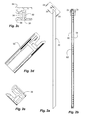
- FIG. 2 a is a top view of an extrusion of a frame of the floor panel of FIG. 1 a;
- FIG. 2 b is a side view of the extrusion of FIG. 2 a;
- FIG. 2 c is a cross-sectional side view of the extrusion of FIG. 2 a taken along line 2 c;
- FIG. 2 d is an end view of the extrusion of FIG. 2 a taken along line 2 d;
- FIG. 2 e is a cross-sectional end view of the extrusion of FIG. 2 a taken along line 2 e;
- FIG. 2 f is a partial perspective end view of the extrusion of FIG. 2 a with magnets and a retaining strip therein;
- FIG. 2 g is a partial perspective end view of the extrusion of FIG. 2 a with magnets and the retaining strip therein;
- FIG. 3 a is an end view of the extrusion of the frame of the floor panel of FIG. 1 a;
- FIGS. 3 b - g are detail views of the extrusion of FIG. 3 a;
- FIG. 4 is a perspective view of a floor panel of the portable dance floor system of FIG. 1 a;
- FIG. 5 is a partial perspective view of the floor panel of the portable dance floor system of FIG. 1 a ;
- FIG. 6 is a top view of the portable dance floor system or assembly in accordance with an embodiment of the invention.
- a portable dance floor system comprising a plurality of floor panels, indicated generally at 10 , in an example implementation in accordance with the invention is shown that is removably couplable together to form a dance floor assembly.
- Such an assembly can be disposed on a support surface 8 ( FIG. 1 c ), such as a floor or the ground.
- the support surface can be carpet, wood, concrete or ever grass or dirt.
- the panels, and thus the assembly can have an upper dance surface that is hard, flat, substantially smooth, and aesthetically pleasing to form a dance floor to receive users or dancers thereon in the act of dancing and similar activities.
- a perimeter edge similar in construction and similarly removably couplable with the floor panels, but with a beveled or inclined upper surface extending from the support surface to the dance surface, can circumscribe the plurality of floor panels to form a gradual transition from the support surface to the dance surface.
- the panels and thus the assembly can have a thickness between 0.5 to 1.5 inches in one aspect, 0.75 to 1.25 inches in another aspect, or of approximately 1.13 inches in another aspect.
- the panels 10 can be formed of a perimeter frame 14 circumscribing a core 18 , and with a dance floor surface 22 substantially covering the frame and core.
- the core 18 can include a honeycomb 26 with vertically oriented walls and vertically oriented cavities extending in a direction of a thickness of the floor.
- the honeycomb can be formed of or can include aluminum, and can be an aluminum honeycomb core.
- the frame 14 can include an extrusion 30 with an outwardly facing channel 34 having an outward facing opening 36 (or having a reduced opening 38 with respect to the bores 62 ).
- the extrusion 30 can have an elongated cavity 42 behind the channel 34 and oriented along a length or longitude of the extrusion.
- the cavity 42 and the channel 34 can be elongated and parallel with respect to one another.
- the extrusion 30 can be formed of or can include aluminum, or another non-ferrous material.
- the extrusions 30 can be straight with mitered ends welded or held together to form squares (or rectangles, or other shapes with straight multiple sides, such as octagons, etc.).
- the size of the panels can be 3 ⁇ 3 feet, 4 ⁇ 4 feet, etc.
- the perimeter frame 14 and the core 18 can be coupled together to form a solid panel with both the frame and the core contributing the structural integrity of the panel.
- a pair of layers such as an upper and lower layers or skins 46 and 50 , can sandwich the core 18 and the perimeter frame 14 between the layers.
- the layers or skins can be aluminum and can be adhered to the core and the frame. Thus, the layers or skins can extend over and under the core and substantially all of the frame.
- the frame, core and layers form a stiff, rigid panel that is capable of retaining its shape and flatness, even in more extreme conditions, including humidity and heat. It will be appreciated that the aluminum materials of the core, frame and layers can resist warping due to moisture and heat, including thermally induced stress.
- the dance floor surface 22 is disposed over the upper layer or skin 46 , and substantially covers the frame 14 .
- the dance floor surface can be a laminate.
- the lower layer or skin 50 can have an exposed bottom surface that can directly contact or abut the support surface 8 .
- the panels can be used outdoors on damp or wet surfaces.
- Both the upper and lower outer edges of the extrusion 30 can include a lip, such as an upper outer lip 54 and a lower outer lip 58 .
- the upper outer lip 54 forms a shallow upper cavity on a top of the frame.
- the upper layer 46 and the dance floor surface 22 can be disposed in the upper cavity.
- the outer perimeter edges of the upper layer 46 and the dance floor surface 22 can extend substantially to the upper outer lip 54 ; and the uppermost surface of the dance floor surface and the lip can terminate at substantially the same elevational height and be substantially flush to provide a smooth surface.
- the lower outer lip 58 on the extrusion 30 forms a shallow bottom cavity on a bottom of the frame.
- the lower aluminum layer 50 can be disposed in the shallow bottom cavity.
- the outer perimeter edge of the lower layer 50 can extend substantially to the lower outer lip 58 ; and the lowermost surface of the lower layer and the lower outer lip can be substantially flush to provide a smoother surface to resist snagging on the support surface.
- the floor panels can have a magnetic retention system that releasably couples adjacent panels together.
- the magnets can have a floating retention system to allow some play or movement of the magnets.
- a plurality of bores 62 can extend into the extrusion 30 transverse to a longitudinal axis thereof, from a back of the extrusion, into the channel 34 , and to the reduced opening or lips 38 or flanges thereof.
- the plurality of bores 62 is each wider than the channel 34 and each extends from a bottom of the channel 34 to short of the outward facing opening 36 to form a reduced width with respect to the bore and defining the pair of opposing lips 38 extending inward over the bore.
- the bores 62 can be, or can have diameters, larger than the width of the channel, but less than the reduced opening.
- a plurality of magnets 66 can each be disposed in a different one of the plurality of bores 62 .
- the plurality of magnets 66 each has a length extending from the pair of lips 38 into a respective bore 62 in the bottom of the channel.
- the magnets 66 are prevented from exiting the opening 36 of the channel by the lips 38 , and are prevented from traveling along the channel by their larger diameters in the bores, and being disposed in the bore in the bottom of the channel.
- the bores 62 can be formed by drilling the extrusion 30 from behind; and the magnets 66 inserted from behind through the opening or leading end of the bore.
- a retaining strip 70 can be disposed in the elongated cavity 42 , and can hold the plurality of magnets 66 between in the plurality of bores 62 between the retaining strip and the reduced opening or lips.
- the retaining strip can be inserted into the elongated cavity from an end of the extrusion after the magnets have been inserted.
- the magnets are physically maintained in the bores by the bore walls and the lips on one end and the retraining strip on the other end, without the use of mechanical fasteners or chemical adhesives.
- the size (diameter and/or length) of the magnets is less than the size of the bores (diameter and/or length) and there is a space or gap therebetween such that the magnets have a limited range of movement in the bores.
- the retaining strip 70 and the extrusion 30 can be non-ferrous; and the plurality of magnets 66 can have a diameter smaller than a diameter of the plurality of the bores 62 , or the plurality of magnets 66 can have a length shorter than a distance from the reduced opening or lips to the retaining strip, or both, such that the plurality of magnets 66 are movable within the plurality of bores 62 .
- the magnets can be or can include neodymium.
- a rib or blade 74 can be disposed in and extend from a channel 34 in an adjacent panel.
- the rib or blade 74 can be ferrous, such as steal, to make a magnetic connection with the magnets between the adjacent panels.
- the rib or blade 74 can form a vertical lock between the panels to resist the panels from displacing vertically with respect to one another.
- the panels can be formed by extruding the extrusion and cutting the extrusion to length and mitering the ends.
- the bores can be drilled.
- the magnets and retaining strips can be inserted.
- the ribs or blades can be inserted and secured.
- the cut extrusions can be welded together.
- the core can be cut to size and placed in the frame.
- the upper and lower layers can be cut to size and placed in the shallow cavities and adhered to the core and the frame.
- the dance floor surface can be adhered to the upper layer.
Abstract
Description
Claims (20)
Priority Applications (2)
| Application Number | Priority Date | Filing Date | Title |
|---|---|---|---|
| US13/908,852 US8844207B2 (en) | 2012-06-04 | 2013-06-03 | Portable dance floor panel with floating magnet retention system |
| CA2852895A CA2852895C (en) | 2013-06-03 | 2014-05-30 | Portable dance floor panel with floating magnet retention system |
Applications Claiming Priority (2)
| Application Number | Priority Date | Filing Date | Title |
|---|---|---|---|
| US201261655371P | 2012-06-04 | 2012-06-04 | |
| US13/908,852 US8844207B2 (en) | 2012-06-04 | 2013-06-03 | Portable dance floor panel with floating magnet retention system |
Publications (2)
| Publication Number | Publication Date |
|---|---|
| US20140245692A1 US20140245692A1 (en) | 2014-09-04 |
| US8844207B2 true US8844207B2 (en) | 2014-09-30 |
Family
ID=51420190
Family Applications (1)
| Application Number | Title | Priority Date | Filing Date |
|---|---|---|---|
| US13/908,852 Active US8844207B2 (en) | 2012-06-04 | 2013-06-03 | Portable dance floor panel with floating magnet retention system |
Country Status (1)
| Country | Link |
|---|---|
| US (1) | US8844207B2 (en) |
Cited By (5)
| Publication number | Priority date | Publication date | Assignee | Title |
|---|---|---|---|---|
| EP2052700A1 (en) | 2007-09-26 | 2009-04-29 | Microchips, Inc. | Drug delivery device and method for use with prosthetic device implantation |
| US9567767B2 (en) * | 2015-03-31 | 2017-02-14 | Treeline Outdoors | Vehicle roof-top tent |
| USD782075S1 (en) * | 2015-08-31 | 2017-03-21 | United Construction Products, Inc. | Flooring tile |
| USD788948S1 (en) * | 2017-01-04 | 2017-06-06 | United Construction Products, Inc. | Flooring tile |
| US11530535B2 (en) * | 2019-09-19 | 2022-12-20 | Kadeya Enterprise Co., Ltd | Dividing screen structure |
Families Citing this family (5)
| Publication number | Priority date | Publication date | Assignee | Title |
|---|---|---|---|---|
| CN105296433B (en) | 2014-08-01 | 2018-02-09 | 中山康方生物医药有限公司 | A kind of CTLA4 antibody, its medical composition and its use |
| US10208489B2 (en) * | 2015-03-30 | 2019-02-19 | Exploring, Inc. | Raised flooring system and assembly method with magnetically-attached flooring surface |
| WO2018035710A1 (en) | 2016-08-23 | 2018-03-01 | Akeso Biopharma, Inc. | Anti-ctla4 antibodies |
| US10408427B2 (en) * | 2017-03-03 | 2019-09-10 | Tahwanda Matthews | Portable fashion modeling runway |
| US20190078598A1 (en) * | 2017-09-12 | 2019-03-14 | Central Graphics And Container Group Ltd. | Panel lock construct |
Citations (13)
| Publication number | Priority date | Publication date | Assignee | Title |
|---|---|---|---|---|
| US3512324A (en) * | 1968-04-22 | 1970-05-19 | Lola L Reed | Portable sectional floor |
| US3852935A (en) | 1972-09-22 | 1974-12-10 | H Jones | Magnetic wall stud |
| US5117596A (en) * | 1990-01-05 | 1992-06-02 | Wenger Corporation | Portable dance floor |
| WO1996004441A1 (en) | 1994-07-29 | 1996-02-15 | Sico Incorporated | Floor panel |
| US5634309A (en) * | 1992-05-14 | 1997-06-03 | Polen; Rodney C. | Portable dance floor |
| US6189283B1 (en) | 1995-12-05 | 2001-02-20 | Sico Incorporated | Portable floor |
| US6446413B1 (en) * | 2001-01-22 | 2002-09-10 | Folia Industries Inc. | Portable graphic floor system |
| US20030042256A1 (en) * | 2001-09-05 | 2003-03-06 | Johnson Burton M. | Floating cover |
| EP1830014A1 (en) | 2006-03-01 | 2007-09-05 | Nicolás Moraleja Alonso | Flooring system with removable magnetic flooring modules for constructing the raised floor of a computer room |
| US20100086377A1 (en) * | 2008-10-04 | 2010-04-08 | De Mola Manuel Loret | Vibration isolation fastener insert |
| US20100319291A1 (en) * | 2008-05-15 | 2010-12-23 | Valinge Innovation Ab | Mechanical locking of floor panels |
| US8033074B2 (en) | 2006-07-11 | 2011-10-11 | Valinge Innovation Ab | Mechanical locking of floor panels with a flexible bristle tongue |
| US8181416B2 (en) | 2004-10-22 | 2012-05-22 | Valinge Innovation Ab | Mechanical locking system for floor panels |
-
2013
- 2013-06-03 US US13/908,852 patent/US8844207B2/en active Active
Patent Citations (14)
| Publication number | Priority date | Publication date | Assignee | Title |
|---|---|---|---|---|
| US3512324A (en) * | 1968-04-22 | 1970-05-19 | Lola L Reed | Portable sectional floor |
| US3852935A (en) | 1972-09-22 | 1974-12-10 | H Jones | Magnetic wall stud |
| US5117596A (en) * | 1990-01-05 | 1992-06-02 | Wenger Corporation | Portable dance floor |
| US5634309A (en) * | 1992-05-14 | 1997-06-03 | Polen; Rodney C. | Portable dance floor |
| WO1996004441A1 (en) | 1994-07-29 | 1996-02-15 | Sico Incorporated | Floor panel |
| US6189283B1 (en) | 1995-12-05 | 2001-02-20 | Sico Incorporated | Portable floor |
| US6446413B1 (en) * | 2001-01-22 | 2002-09-10 | Folia Industries Inc. | Portable graphic floor system |
| US20030042256A1 (en) * | 2001-09-05 | 2003-03-06 | Johnson Burton M. | Floating cover |
| US8181416B2 (en) | 2004-10-22 | 2012-05-22 | Valinge Innovation Ab | Mechanical locking system for floor panels |
| EP1830014A1 (en) | 2006-03-01 | 2007-09-05 | Nicolás Moraleja Alonso | Flooring system with removable magnetic flooring modules for constructing the raised floor of a computer room |
| US8033074B2 (en) | 2006-07-11 | 2011-10-11 | Valinge Innovation Ab | Mechanical locking of floor panels with a flexible bristle tongue |
| US20100319291A1 (en) * | 2008-05-15 | 2010-12-23 | Valinge Innovation Ab | Mechanical locking of floor panels |
| US8112967B2 (en) | 2008-05-15 | 2012-02-14 | Valinge Innovation Ab | Mechanical locking of floor panels |
| US20100086377A1 (en) * | 2008-10-04 | 2010-04-08 | De Mola Manuel Loret | Vibration isolation fastener insert |
Non-Patent Citations (4)
| Title |
|---|
| Mity-Lite; Magnattach Portable Dance Floor; ©2011; 2 pages. |
| Mity-Lite; Sales Literature; Magnattach® Portable Dance Floor; http://www.mitylite.com/magnattach/index.html; accessed on May 31, 2012; 3 pages. |
| Mity-Lite; Specifications; Magnattach® Portable Dance Floor; Durable Lightweight Tables & Chairs; 1 page; Apr. 2011. |
| Versare Portable Dance Floor; http://web.archive.org/web/20100314163519/http://www.portableplatforms.com/products/... Accessed on May 31, 2012; 1 page. |
Cited By (5)
| Publication number | Priority date | Publication date | Assignee | Title |
|---|---|---|---|---|
| EP2052700A1 (en) | 2007-09-26 | 2009-04-29 | Microchips, Inc. | Drug delivery device and method for use with prosthetic device implantation |
| US9567767B2 (en) * | 2015-03-31 | 2017-02-14 | Treeline Outdoors | Vehicle roof-top tent |
| USD782075S1 (en) * | 2015-08-31 | 2017-03-21 | United Construction Products, Inc. | Flooring tile |
| USD788948S1 (en) * | 2017-01-04 | 2017-06-06 | United Construction Products, Inc. | Flooring tile |
| US11530535B2 (en) * | 2019-09-19 | 2022-12-20 | Kadeya Enterprise Co., Ltd | Dividing screen structure |
Also Published As
| Publication number | Publication date |
|---|---|
| US20140245692A1 (en) | 2014-09-04 |
Similar Documents
| Publication | Publication Date | Title |
|---|---|---|
| US8844207B2 (en) | Portable dance floor panel with floating magnet retention system | |
| US9366030B2 (en) | Wall panel system | |
| US11939765B2 (en) | Sound damping wallboard and method of forming a sound damping wallboard | |
| ES2652033T3 (en) | Multilayer elastic floor panel that has a reinforced PVC core | |
| US7698872B2 (en) | Portable panel construction and method for making the same | |
| US8898975B2 (en) | Dry-hang wall panel using a thin stone slab | |
| CA2740502C (en) | Ribbed backed panels | |
| KR200469749Y1 (en) | Magnetic mat block | |
| US8850772B1 (en) | Interlocking cladding panel trim pieces and methods of use | |
| US9290936B2 (en) | Portable floor | |
| CA2852895C (en) | Portable dance floor panel with floating magnet retention system | |
| US6295768B1 (en) | Prefabricated structure | |
| EP2949831A1 (en) | Portable Dance Floor Panel with Floating Magnet Retention System | |
| CN218814708U (en) | Anti-crack heat-insulation quick-assembly wallboard | |
| CN201040923Y (en) | Building elevation plane combined type mold | |
| CN215253591U (en) | High-strength lightweight heat-preservation extruded sheet for indoor decoration and mounting outer frame thereof | |
| JP6195240B2 (en) | Stair equipment | |
| CN212729483U (en) | Carpet piece and carpet with hidden lock structure | |
| RU128635U1 (en) | Dismountable MODULAR BUILDING CONSTRUCTION | |
| JP2004052362A (en) | Wall structure | |
| JP2018087412A (en) | Door body | |
| CN202559635U (en) | Composite ceiling pinch plate | |
| JP6158554B2 (en) | Wall panel for interior | |
| JPH11181952A (en) | Construction member | |
| WO2009036767A1 (en) | Building panel |
Legal Events
| Date | Code | Title | Description |
|---|---|---|---|
| AS | Assignment |
Owner name: MITY-LITE, INC., UTAH Free format text: ASSIGNMENT OF ASSIGNORS INTEREST;ASSIGNORS:BOWERS, BRIAN;HEATH, MITCHELL;SIGNING DATES FROM 20130614 TO 20130625;REEL/FRAME:031021/0101 |
|
| STCF | Information on status: patent grant |
Free format text: PATENTED CASE |
|
| AS | Assignment |
Owner name: JPMORGAN CHASE BANK, N.A., AS LENDER, CALIFORNIA Free format text: SECURITY INTEREST;ASSIGNORS:MITY-LITE, INC.;MITY, INC.;BRODA USA, INC.;REEL/FRAME:034862/0104 Effective date: 20150130 |
|
| AS | Assignment |
Owner name: PNC BANK, NATIONAL ASSOCIATION, TEXAS Free format text: SECURITY INTEREST;ASSIGNORS:MITY-LITE, INC.;BRODA USA, INC.;REEL/FRAME:040804/0022 Effective date: 20161229 Owner name: PNC BANK, NATIONAL ASSOCIATION, TEXAS Free format text: SECURITY INTEREST;ASSIGNOR:MITY, INC.;REEL/FRAME:040805/0020 Effective date: 20161229 Owner name: MITY, INC., UTAH Free format text: RELEASE BY SECURED PARTY;ASSIGNOR:JPMORGAN CHASE BANK, N.A.;REEL/FRAME:040805/0896 Effective date: 20161229 Owner name: BRODA USA, INC., UTAH Free format text: RELEASE BY SECURED PARTY;ASSIGNOR:JPMORGAN CHASE BANK, N.A.;REEL/FRAME:040805/0896 Effective date: 20161229 Owner name: MITY-LITE, INC., UTAH Free format text: RELEASE BY SECURED PARTY;ASSIGNOR:JPMORGAN CHASE BANK, N.A.;REEL/FRAME:040805/0896 Effective date: 20161229 |
|
| AS | Assignment |
Owner name: JPMORGAN CHASE BANK, N.A., UTAH Free format text: RELEASE BY SECURED PARTY;ASSIGNORS:MITY-LITE, INC.;BRODA USA, INC.;MITY, INC.;REEL/FRAME:043626/0847 Effective date: 20161229 |
|
| FEPP | Fee payment procedure |
Free format text: ENTITY STATUS SET TO UNDISCOUNTED (ORIGINAL EVENT CODE: BIG.) |
|
| MAFP | Maintenance fee payment |
Free format text: PAYMENT OF MAINTENANCE FEE, 4TH YEAR, LARGE ENTITY (ORIGINAL EVENT CODE: M1551) Year of fee payment: 4 |
|
| AS | Assignment |
Owner name: ECLIPSE BUSINESS CAPITAL LLC, AS AGENT, ILLINOIS Free format text: SECURITY INTEREST;ASSIGNORS:MITY-LITE INC.;BRODA USA INC.;HOLSAG CANADA;AND OTHERS;REEL/FRAME:059258/0559 Effective date: 20220311 |
|
| AS | Assignment |
Owner name: MITY, INC., UTAH Free format text: RELEASE BY SECURED PARTY;ASSIGNOR:PNC BANK, NATIONAL ASSOCIATION;REEL/FRAME:059448/0258 Effective date: 20220311 Owner name: BRODA USA, INC., UTAH Free format text: RELEASE BY SECURED PARTY;ASSIGNOR:PNC BANK, NATIONAL ASSOCIATION;REEL/FRAME:059448/0258 Effective date: 20220311 Owner name: MITY-LITE, INC., UTAH Free format text: RELEASE BY SECURED PARTY;ASSIGNOR:PNC BANK, NATIONAL ASSOCIATION;REEL/FRAME:059448/0258 Effective date: 20220311 |
|
| FEPP | Fee payment procedure |
Free format text: 7.5 YR SURCHARGE - LATE PMT W/IN 6 MO, LARGE ENTITY (ORIGINAL EVENT CODE: M1555); ENTITY STATUS OF PATENT OWNER: LARGE ENTITY |
|
| MAFP | Maintenance fee payment |
Free format text: PAYMENT OF MAINTENANCE FEE, 8TH YEAR, LARGE ENTITY (ORIGINAL EVENT CODE: M1552); ENTITY STATUS OF PATENT OWNER: LARGE ENTITY Year of fee payment: 8 |