US8847451B2 - Combination radial/axial electromagnetic actuator with an improved axial frequency response - Google Patents
Combination radial/axial electromagnetic actuator with an improved axial frequency response Download PDFInfo
- Publication number
- US8847451B2 US8847451B2 US13/045,379 US201113045379A US8847451B2 US 8847451 B2 US8847451 B2 US 8847451B2 US 201113045379 A US201113045379 A US 201113045379A US 8847451 B2 US8847451 B2 US 8847451B2
- Authority
- US
- United States
- Prior art keywords
- axial
- pole
- radial
- magnetic
- electromagnetic actuator
- Prior art date
- Legal status (The legal status is an assumption and is not a legal conclusion. Google has not performed a legal analysis and makes no representation as to the accuracy of the status listed.)
- Active, expires
Links
Images


Classifications
-
- H—ELECTRICITY
- H02—GENERATION; CONVERSION OR DISTRIBUTION OF ELECTRIC POWER
- H02K—DYNAMO-ELECTRIC MACHINES
- H02K7/00—Arrangements for handling mechanical energy structurally associated with dynamo-electric machines, e.g. structural association with mechanical driving motors or auxiliary dynamo-electric machines
- H02K7/08—Structural association with bearings
- H02K7/09—Structural association with bearings with magnetic bearings
-
- F—MECHANICAL ENGINEERING; LIGHTING; HEATING; WEAPONS; BLASTING
- F16—ENGINEERING ELEMENTS AND UNITS; GENERAL MEASURES FOR PRODUCING AND MAINTAINING EFFECTIVE FUNCTIONING OF MACHINES OR INSTALLATIONS; THERMAL INSULATION IN GENERAL
- F16C—SHAFTS; FLEXIBLE SHAFTS; ELEMENTS OR CRANKSHAFT MECHANISMS; ROTARY BODIES OTHER THAN GEARING ELEMENTS; BEARINGS
- F16C32/00—Bearings not otherwise provided for
- F16C32/04—Bearings not otherwise provided for using magnetic or electric supporting means
- F16C32/0406—Magnetic bearings
- F16C32/044—Active magnetic bearings
- F16C32/0459—Details of the magnetic circuit
- F16C32/0461—Details of the magnetic circuit of stationary parts of the magnetic circuit
- F16C32/0465—Details of the magnetic circuit of stationary parts of the magnetic circuit with permanent magnets provided in the magnetic circuit of the electromagnets
-
- F—MECHANICAL ENGINEERING; LIGHTING; HEATING; WEAPONS; BLASTING
- F16—ENGINEERING ELEMENTS AND UNITS; GENERAL MEASURES FOR PRODUCING AND MAINTAINING EFFECTIVE FUNCTIONING OF MACHINES OR INSTALLATIONS; THERMAL INSULATION IN GENERAL
- F16C—SHAFTS; FLEXIBLE SHAFTS; ELEMENTS OR CRANKSHAFT MECHANISMS; ROTARY BODIES OTHER THAN GEARING ELEMENTS; BEARINGS
- F16C32/00—Bearings not otherwise provided for
- F16C32/04—Bearings not otherwise provided for using magnetic or electric supporting means
- F16C32/0406—Magnetic bearings
- F16C32/044—Active magnetic bearings
- F16C32/0474—Active magnetic bearings for rotary movement
- F16C32/0485—Active magnetic bearings for rotary movement with active support of three degrees of freedom
-
- F—MECHANICAL ENGINEERING; LIGHTING; HEATING; WEAPONS; BLASTING
- F16—ENGINEERING ELEMENTS AND UNITS; GENERAL MEASURES FOR PRODUCING AND MAINTAINING EFFECTIVE FUNCTIONING OF MACHINES OR INSTALLATIONS; THERMAL INSULATION IN GENERAL
- F16C—SHAFTS; FLEXIBLE SHAFTS; ELEMENTS OR CRANKSHAFT MECHANISMS; ROTARY BODIES OTHER THAN GEARING ELEMENTS; BEARINGS
- F16C2360/00—Engines or pumps
- F16C2360/44—Centrifugal pumps
-
- F—MECHANICAL ENGINEERING; LIGHTING; HEATING; WEAPONS; BLASTING
- F16—ENGINEERING ELEMENTS AND UNITS; GENERAL MEASURES FOR PRODUCING AND MAINTAINING EFFECTIVE FUNCTIONING OF MACHINES OR INSTALLATIONS; THERMAL INSULATION IN GENERAL
- F16C—SHAFTS; FLEXIBLE SHAFTS; ELEMENTS OR CRANKSHAFT MECHANISMS; ROTARY BODIES OTHER THAN GEARING ELEMENTS; BEARINGS
- F16C2380/00—Electrical apparatus
- F16C2380/26—Dynamo-electric machines or combinations therewith, e.g. electro-motors and generators
-
- H—ELECTRICITY
- H02—GENERATION; CONVERSION OR DISTRIBUTION OF ELECTRIC POWER
- H02K—DYNAMO-ELECTRIC MACHINES
- H02K2205/00—Specific aspects not provided for in the other groups of this subclass relating to casings, enclosures, supports
- H02K2205/03—Machines characterised by thrust bearings
Definitions
- This disclosure relates to generating electromagnetic forces, and, more particularly, to generating radial and axial electromagnetic forces using a combination radial/axial electromagnetic actuator.
- Equipment and machinery often contain moving (e.g., rotating, translating) members, which require support during operation.
- a bearing, or similar device may be used to support the moving member. Although some bearings may require direct contact with the member to provide the necessary support, some applications benefit from non-contact, or nearly non-contact, support for the member.
- a magnetic bearing uses an electromagnetic actuator to apply a controlled electromagnetic force to support the moving member in a non-contact, or nearly non-contact, manner. The non-contact or nearly non-contact support provided by the magnetic bearing can provide frictionless or nearly frictionless movement of the member in both the axial and radial directions.
- an electromagnetic actuator may include a body having a rotational axis.
- a first axial pole may reside apart from the body, the first axial pole adjacent a first end facing surface of the body and adapted to communicate magnetic flux across a gap with the first end facing surface of the body.
- a second axial pole may reside apart from the body, the second axial pole adjacent a second end facing surface of the body and adapted to communicate magnetic flux with the second end facing surface of the body.
- a lamination stack may include electrically isolated steel laminations.
- An axial backiron, the first axial pole, the second axial pole, and the lamination stack may be magnetically linked and define an axial magnetic control circuit.
- a first radial pole may reside apart from the body, the first radial pole adjacent a lateral facing surface of the body and adapted to communicate a magnetic flux with the lateral facing surface of the body and at least one of the first axial pole or the second axial pole.
- the body, the first radial pole, and one of the first axial pole or the second axial pole may define a magnetic bias circuit.
- At least one lamination stack may be rigidly affixed to one of the first axial pole or the second axial pole, the lamination stack comprising electrically isolated steel laminations stacked in a direction parallel or substantially parallel to the rotational axis.
- substantially parallel includes the parallel orientation as well as orientations that are slightly off of the parallel direction with respect to the rotational axis of the body.
- At least one lamination stack may be rigidly affixed to the axial backiron and the electrically isolated steel laminations may be stacked in a direction substantially orthogonal to the rotational axis.
- substantially orthogonal includes the orthogonal direction and directions that are slightly off the orthogonal relative to the rotational axis.
- a second radial pole may be adjacent a lateral facing surface of the body and adapted to communicate a magnetic flux with the lateral facing surface of the body, the first radial pole and at least one of the first axial pole or the second axial pole.
- the body, the second radial pole, and the first axial pole or the second axial pole may define a magnetic bias circuit.
- the body, the first radial pole, and the second radial pole may define a radial magnetic control circuit.
- the end facing surface of the body may be substantially orthogonal to the rotational axis.
- substantially orthogonal is meant to include orientations that are orthogonal or normal to the rotational axis, as well as orientations that are slightly off of the normal to the rotational axis.
- the body may incorporate a magnetically permeable actuator target, the actuator target adapted to communicate a magnetic flux.
- a magnetic element may be configured to produce magnetic bias flux in the magnetic bias circuit.
- an axial coil may be adapted to produce a magnetic flux in the axial magnetic control circuit.
- a radial coil may be adapted to produce a magnetic flux in the radial magnetic control circuit.
- the magnetic flux entering the end facing surface of the body exerts an axial force on the body.
- the magnetic fluxes entering the lateral surface of the body exert radial forces on the body.
- the axial force is proportional to the magnetic flux in the axial magnetic control circuit.
- the radial forces are proportional to the magnetic fluxes in the radial magnetic control circuits.
- the lamination stack includes a first annular lamination and a second annular lamination, the first and second annular laminations defining an annular lamination stack coaxial to the rotational axis.
- the first annular lamination is a first disjointed annular element defining a first air gap between disjoined segments of the annular element and the second annular lamination is a second disjointed annular element defining a second air gap between disjoined segments of the second annular element.
- the first air gap resides misaligned from the second air gap in the annular lamination stack.
- the first axial pole includes a first segment and a second segment.
- the first segment and the second segment are electrically isolated from each other.
- the first segment includes a first lamination segment and a second lamination segment, the first and second lamination segment defining a lamination stack.
- the first lamination segment and the second lamination segment are electrically isolated from each other.
- a method for exerting a time-varying force on a body along a body axis may include communicating a first bias magnetic flux through a first axial facing surface of the body. The method may also include communicating a second bias magnetic flux through a second axial facing surface of the body.
- a time-varying axial control magnetic flux may be generated and directed towards the first and the second axial facing surfaces of the body in a stationary magnetic control circuit, the stationary magnetic control circuit including at least one electrically isolated steel lamination stack stacked in a direction substantially orthogonal to the control magnetic flux.
- an electric machine system may include a stator and a rotor.
- the rotor may have a rotational axis configured to move relative to the stator.
- the electric machine may also include an electromagnetic actuator subassembly that may include a cylindrical actuator target rigidly mounted on the rotor.
- a first axial pole may reside apart from the actuator target, the first axial pole adjacent a first end facing surface of the actuator target and adapted to communicate magnetic flux across a gap with the first end facing surface of the actuator target.
- a second axial pole may reside apart from the body, the second axial pole adjacent a second end facing surface of the body and adapted to communicate magnetic flux with the second end facing surface of the body.
- An axial backiron may magnetically link the first axial pole and the second axial pole.
- a lamination stack may include electrically isolated steel laminations.
- the body, the first axial pole, the second axial pole, the lamination stack, and the axial backiron may be magnetically linked and define an axial magnetic control circuit.
- An axial control conductive coil may be adapted to produce a magnetic flux in the axial magnetic control circuit.
- a plurality of radial poles may reside apart from the body, the plurality of radial poles adjacent a lateral facing surface of the body and adapted to communicate magnetic fluxes with the lateral facing surface of the body.
- the body and the plurality of radial poles define a plurality of radial magnetic control circuits, and the plurality of radial poles may be adapted to communicate magnetic fluxes with the lateral facing surface of the body and at least one of the first axial pole or the second axial pole.
- the body, the plurality of radial poles, and at least one of the first axial pole or the second axial pole define a magnetic bias circuit.
- Radial control conductive coils may be wound around the radial poles and adapted to produce a magnetic flux in the radial magnetic control circuit.
- One or more position sensors may be configured to sense a position of the body.
- At least one control electronics package may be configured to control the magnetic fluxes in the axial magnetic control circuit and the radial magnetic control circuits.
- the body is coupled to a driven load, the driven load comprising at least one of a flywheel, a compressor, a generator, or an expander.
- the body is coupled to a driver, the driver comprising at least one of a motor, an engine, or a turbine.
- the electronic control package is configured to control the magnetic fluxes in the radial magnetic control circuits by energizing the control coil around each of the plurality of radial poles with a control current.
- the electronic control package is further configured to energize the axial and radial control conductive coil with control currents in response to changes of signals from the position sensors so that the rotor is supported by electromagnetic forces without a mechanical contact with the stator.
- FIG. 1 shows a perspective partial cross-sectional view of an electromagnetic actuator in accordance with the present disclosure and illustrates generating an axial force.
- FIG. 2 shows a perspective view of an electromagnetic actuator in accordance with the present disclosure with a portion of an axial pole cut out to reveal the laminated axial backiron inserts.
- FIG. 3 shows an axial cross-sectional view of an electromagnetic actuator in accordance with the present disclosure and illustrates generating a radial force.
- FIG. 4 shows a radial cross-sectional view of a combination radial/axial electromagnetic actuator and illustrates a distribution of an AC magnetic control flux without laminated axial pole inserts and laminated axial backiron inserts.
- FIG. 5 shows a radial cross-sectional view of a combination radial/axial electromagnetic actuator according to the present disclosure and illustrates a distribution of an AC magnetic control flux with laminated axial pole inserts and laminated axial backiron inserts.
- FIG. 6 shows views of an electromagnetic actuator according to the present disclosure and illustrates induction of a circular current in a laminated axial pole insert when producing a time-varying axial control force.
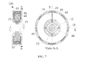
- FIG. 7 shows views of an electromagnetic actuator according to the present disclosure and illustrates a manner of preventing a circular current in the laminated axial pole insert.
- FIG. 8 shows an exploded view of the laminations of a laminated axial pole insert, each lamination including a slot rotated with respect to similar slots in the neighboring laminations.
- FIG. 9 shows an exploded view of an embodiment of a combination radial/axial electromagnetic actuator with an axial pole composed of separate segments.
- FIG. 10 is a graph showing an improvement in the axial AC gain of an example combination radial/axial actuator due to the usage of laminated axial pole inserts and laminated axial backiron inserts.
- FIG. 11 is a graph showing an improvement in the phase difference between a force exerted by an example combination radial/axial actuator and an axial control current due to the usage of laminated axial pole inserts and laminated axial backiron inserts.
- FIG. 12 is a cross-sectional schematic of an electric machine system incorporating an embodiment of the combination radial/axial electromagnetic actuator in accordance with the present disclosure.
- This disclosure relates to generating electromagnetic forces through an electromagnetic actuator and, more particularly, to generating radial and axial electromagnetic forces through a combination radial/axial electromagnetic actuator with an improved axial frequency response.
- Permanent-Magnet-Biased Homopolar Combination Axial/Radial Electromagnetic Actuators offer advantages of small part count, small size and weight, and short axial length.
- One of the important applications of such an actuator is in Active Magnetic Bearings (AMBs) providing non-contact support of objects using electromagnetic forces.
- AMBs Active Magnetic Bearings
- the combination actuator may improve rotordynamic response due to a more compact design than a combination of separate radial and axial actuators.
- the axial channel of a combination actuator may exhibit lower bandwidth characteristics as compared to a dedicated axial actuator. This may complicate the axial control of an AMB system and degrades its performance.
- the axial bandwidth limitation may be caused by eddy currents induced in the components of the axial magnetic control circuit, which are made metallic for practical reasons, when an alternating axial control current is applied. These currents result in both amplitude attenuation and a phase lag of the magnetic control flux, which subsequently affect the control force. Because in combination actuators the axial magnetic control circuit is significantly longer than in conventional dedicated axial electromagnetic actuators, it may result in larger amplitude attenuations and phase lags.
- FIG. 1 shows a partial cross-sectional view of an electromagnetic actuator 100 in accordance with the present disclosure and illustrates generating an axial force 32 .
- Bias magnetic flux 1 generated by permanent magnet 3 , is directed by axial pole 5 to axial gap 7 .
- the axial pole 5 may consist of a solid-steel portion 40 and a laminated axial pole insert 42 composed of electrically insulated electrical steel laminations stacked in the axial direction Z 17 .
- the bias flux 1 then passes through axial gap 7 and enters the actuator target 9 .
- magnetic bias flux 2 generated by permanent magnet 4 , is directed by axial pole 6 to axial gap 8 .
- the axial pole 6 may consist of a solid-steel portion 44 and a laminated axial pole insert 46 composed of electrically insulated electrical steel laminations stacked in the axial direction Z 17 .
- the bias flux 2 then passes through axial gap 8 and enters the actuator target 9 .
- Bias fluxes 1 and 2 merge together and exit through the radial gaps 10 a through 10 d (shown in FIG. 3 ) into the radial actuator pole assembly 11 .
- the electrically insulated electrical steel lamination inserts 42 and 46 may be imbedded into the axial poles 5 and 6 , respectively.
- the lamination inserts 42 and 46 may be implanted into axial poles 5 and 6 , respectively, or may be attached mechanically to the axial poles 5 and 6 or to magnets 3 and 4 , respectively.
- the term imbedded may include different ways of integrating, inserting, attaching, affixing, or otherwise establishing a connection such that the a magnetic flux can be communicated between the magnets 3 and 4 , the first pole and second pole 5 and 6 , respectively, and the laminations 42 and 46 , respectively.
- the coil 12 carries axial control current 30 flowing around the actuator axis 17 .
- This current 30 produces magnetic axial control flux 13 , which may propagate through axial pole 5 , axial gap 7 , actuator target 9 , axial gap 8 , axial pole 6 , and axial backiron 14 .
- the axial backiron 14 may consist of a solid steel portion 48 and laminated axial backiron inserts 50 composed of electrically insulated electrical steel laminations stacked in a tangential direction with respect to the actuator axis 17 .
- FIG. 2 shows the actuator 100 with a quarter of the solid portion 44 of the axial pole 6 cut out to reveal details of how the laminated axial backiron inserts 50 may be inserted into slots in the solid portion 48 of the axial backiron 14 .
- the axial backiron inserts 50 may be imbedded into the axial backiron 14 .
- the axial backiron inserts 50 may otherwise be affixed to the axial backiron such that magnetic flux can be communicated between the axial backiron 14 and the axial backiron inserts 50 .
- the axial backiron inserts 50 may be lamination stacks stacked in a direction orthogonal or substantially orthogonal to the rotational axis of the actuator target 9 .
- the magnitude and direction of the magnetic axial control flux 13 can be changed by changing the current 30 in the coil 12 . If the magnetic axial control flux 13 is zero, the bias flux 1 in the axial gap 7 may be equal or near equal to the bias flux 2 in the axial gap 8 and the net axial electromagnetic force acting on the actuator target 9 may offset towards a zero or near zero net value. If there is a non-zero magnetic axial control flux 13 flowing in the direction shown in FIG. 1 , the magnetic axial control flux 13 adds to the bias flux 1 in the axial gap 7 , but subtracts from the bias flux 2 in the axial gap 8 .
- the magnetic actuator 100 may also provide radial forces on the same actuator target 9 .
- the mechanism of the radial force generation is explained in FIG. 3 .
- FIG. 3 shows an axial sectional view of an electromagnetic actuator in accordance with the present disclosure and illustrates generating a radial force.
- the radial pole assembly 11 is equipped with at least three radial control poles and control windings around these poles.
- FIG. 3 shows four radial control windings 16 a through 16 d located in slots between the poles 38 a - 38 d .
- the bias fluxes 1 and 2 generated by the magnets 3 and 4 add up in the radial air gaps 10 a through 10 d and flow radially within the radial poles 38 a - 38 d .
- the bias flux density under each pole associated with windings 16 a - 16 d is the same or similar because of the system symmetry. Therefore, the net radial force may approach zero or close to zero.
- the flux distribution can be altered so that a radial force would develop. For example, FIG.
- FIG. 3 shows coils 16 a and 16 c being energized with control currents 20 a and 20 c , respectively. These currents produce radial control flux 22 .
- control flux 22 adds to the combined bias fluxes 1 and 2 , while in the air gap 10 c under the pole associated with the control coil 16 c , it subtracts. Since the flux density will be higher at the top of the target 9 than at the bottom, there will be a radial force F Y 24 acting on the target, directed along the Y-axis 19 upwards in FIG. 3 (e.g., positive Y-direction). Similarly, by energizing windings 16 b and 16 d , a force can be produced in the direction of the X-axis 18 .
- the proposed electromagnetic actuator may also be used to produce only the axial force 32 without the capability of producing radial forces.
- the radial control windings 16 a through 16 d shown in FIG. 3 may be omitted, as well as the slots between the poles 38 a through 38 d accommodating these windings.
- the radial actuator pole assembly 11 and the actuator target 9 may be assembled of magnetically permeable and electrically conductive laminations (e.g., steel laminations) stacked axially and electrically isolated from each other.
- the isolation reduces eddy currents in these components induced when the radial control windings 16 a - 16 d are energized with time-varying currents to produce time-varying radial forces.
- the laminated axial pole inserts 42 and 46 and the laminated axial backiron inserts 50 serve to reduce effects of eddy currents which could be otherwise induced in the axial poles 5 and 6 and axial backiron 14 when the axial control coil 12 is energized with a time-varying current 30 to produce a time-varying axial force F z 32 .
- One of the consequences of having these eddy currents would be having an axial magnetic control flux 13 constrained to thin layers adjacent to the inner surfaces of the axial poles 5 , 6 and the axial backiron 14 as illustrated in FIG. 4 .
- the eddy currents in the axial poles 5 and 6 and the axial backiron 14 can be suppressed by suppressing their conductivities, at least in one direction, in the planes normal to the direction of the magnetic axial control flux 13 .
- the conductivity is suppressed in the axial direction because of the insulation between laminations stacked in this direction.
- the insulation between laminations suppresses the conductivity in the tangential direction.
- the magnetic axial control flux 13 may be able to flow through the entire cross-sections of the inserts 42 , 46 , and 50 as shown in FIG. 5 .
- the axial backiron inserts 50 may be lamination stacks stacked in a direction orthogonal to the rotational axis of the rotor
- the effectiveness of the axial pole inserts 42 and 46 can, optionally, be further improved by interrupting continuous current flow paths around the bearing axis 17 in each lamination. If this interruption is not done, the axial component of the time-varying axial magnetic control flux 13 encircled by the inserts 42 and 46 would induce circular currents in the inserts 42 and 46 flowing around the bearing axis 17 in accordance with Faraday's Law, which would negatively affect the bearing operation.
- FIG. 6 illustrates this principle using the axial pole insert 46 as an example.
- An axial component of a time-varying magnetic axial control flux 13 directed into the page in FIG. 6 induces a circular current 26 around the bearing axis 17 directed counterclockwise according to Faraday's Law.
- FIG. 7 shows views of an electromagnetic actuator according to the present disclosure and illustrates a manner of preventing a circular current in the laminated axial pole insert. It is also possible to introduce a radial slot in each lamination prior to stacking them and then rotate the position of the slot during the stacking as shown in FIG. 8 to achieve more uniform magnetic properties and mechanical strength of the laminated axial pole inserts 42 and 46 compared to FIG. 7 .
- FIG. 8 shows an exploded view of the laminations of a laminated axial pole insert, each lamination including a slot rotated with respect to similar slots in the neighboring laminations.
- FIG. 9 shows an exploded view of an embodiment of a combination radial/axial electromagnetic actuator with an axial pole composed of separate segments.
- the axial pole 6 is replaced with two 180-degree segments 6 a and 6 b , each including its own solid portion 44 a and 44 b , respectively, as well as a laminated insert 46 a and 46 b , respectively.
- the inserts 46 a and 46 b may be electrically isolated from each other to prevent forming a circular current such as current 26 in FIG. 6 .
- the solid portions 44 a and 44 b may also be isolated from each other.
- the axial pole segments 6 a and 6 b can be slid radially into the gap between the actuator target 9 and a higher-diameter portion of the shaft 15 prior to attaching to the rest of the assembly.
- a common axial pole insert 46 such as the one shown in FIG. 1 , 2 , 6 , 7 or 8 mechanically linking together segments of the axial pole solid portions, such as portions 44 a and 44 b shown in FIG. 9 .
- This option may be especially attractive if the shaft 15 increases in diameter outwards from the actuator, as illustrated in FIG. 9 , and the inner diameter of the axial pole insert 46 is larger than the outer diameter of the actuator target 9 .
- the solid axial pole segments 44 a and 44 b can be first slid radially into the gap between the actuator target 9 and a higher-diameter portion of the shaft 15 , then a common axial pole insert 46 can be slid axially over the actuator target 9 and attached to the solid axial pole segments 44 a and 44 b forming axial pole 6 , which later can be attached to the rest of the assembly.
- FIGS. 10 and 11 show improvements in the normalized actuator gain and phase lag, respectively, as functions of frequency that may be achieved by using laminated axial pole inserts and axial backiron inserts in an example combination actuator.
- the actuator axial gain is defined as a ratio of the amplitudes of the axial force 32 and an axial control current 30 .
- the normalized axial actuator gain presented in FIG. 10 is a gain at a particular frequency divided by the gain at zero frequency (DC gain).
- the actuator phase lag presented in FIG. 11 is a difference between the phase of the axial force 32 and the phase of the axial control current 30 .
- the remaining loss of the gain and phase lag are due to eddy currents in the actuator target 9 and tips of the solid portions 44 and 46 of the axial poles 5 and 6 adjacent to the target 9 .
- the target 9 is laminated in the Z direction, which is the direction of the magnetic axial control flux 13 , it is not laminated in the plane normal to the direction of the magnetic axial control flux 13 , and, therefore, eddy currents still can be induced in the target 9 and affect the distribution of the AC magnetic axial control flux 13 .
- FIGS. 1 , 2 , 6 , 7 , and 9 show the combination radial/axial electromagnetic actuator comprising several laminated inserts: two axial pole inserts 42 and 46 and a set of axial backiron inserts 50 . It is also possible to use only some of the inserts shown in these figures, for example, only the axial pole inserts 42 and 46 , or only one of the axial inserts 42 or 46 , or only the axial backiron inserts 50 , or any other combination of the inserts. The improvements to the actuator gain and phase, however, will be greater when a bigger portion of the path of the axial magnetic control flux 13 lies in laminated sections.
- the proposed homopolar combination axial/radial magnetic actuator 100 may be utilized as a part of an Active Magnetic Bearing (AMB) system to support a rotor of a rotational machine without a mechanical contact.
- FIG. 12 shows an example of using an AMB system in an electric rotational machine 1200 .
- the rotational electric machine 1200 can be, for example, an electric compressor including an electric motor 1204 driving an impeller 1206 mounted directly on the motor shaft 1208 .
- the electric motor 1204 shown in FIG. 12 has a rotor 1210 and a stator 1212 .
- the impeller 1206 can be driven by a flow of gas or liquid and spin the rotor 1210 attached to it through the shaft 1208 .
- the motor 1204 can be used as a generator which would convert the mechanical energy of the rotor 1210 into electricity.
- the rotor 1210 of the electric machine 1200 can be supported radially and axially without mechanical contact by means of front and rear radial AMBs 1214 and 1216 .
- the front AMB 1214 provides an axial suspension of the entire rotor 1210 and a radial suspension of the front end of the rotor, whereas the rear AMB 1216 provides only radial suspension of the rear end of the rotor 1210 .
- the AMBs 1214 and 1216 When the AMBs 1214 and 1216 are not working, the rotor rests on the mechanical backup bearings 1220 and 1222 .
- the front backup bearing 1220 may provide the axial support of the entire rotor 1210 and a radial support of the rotor front end, whereas the rear backup bearing 1222 may provide radial support of the rear end of the rotor 1210 .
- the front AMB 1214 consists of a combination radial and axial electromagnetic actuator 1201 per the concepts described herein, radial position sensors 1224 , axial position sensor 1226 and control electronics (not shown).
- the electromagnetic actuator 1201 in accordance with the concepts described herein may be capable of exerting radial and axial forces on the actuator target 1209 firmly mounted on the rotor 1210 .
- the axial force is the force in the direction of Z-axis 1217 and the radial forces are forces in the direction of X-axis 1218 (directed into the page) and the direction of Y-axis 1219 .
- the actuator may have three sets of coils corresponding to each of the axes and the forces may be produced when the corresponding coils are energized with control currents produced by control electronics (not shown).
- the position of the front end of the rotor in space is constantly monitored by non-contact position sensors, such as radial position sensors 1224 and axial position sensors 1226 .
- the non-contact position sensors 1224 can monitor the radial position of the rotor, whereas the position sensor 1226 monitors the axial position of the rotor.
- Signals from the position sensors 1224 and 1226 may be input into the control electronics (not shown), which may generate currents in the control coils of the combination electromagnetic actuator 1201 when it finds that the rotor is deflected from the desired position such that these currents may produce forces pushing the rotor back to the desired position.
- the rear AMB 1216 consists of an electromagnetic actuator 1228 , radial non-contact position sensors 1230 , and control electronics (not shown). It may function similarly to the front AMB 1214 except that it might not be configured to control the axial position of the rotor 1210 because this function is already performed by the front AMB 1214 . Correspondingly, the electromagnetic actuator 1228 may not be able to produce controllable axial force and there may be no axial position sensor
Landscapes
- Engineering & Computer Science (AREA)
- General Engineering & Computer Science (AREA)
- Mechanical Engineering (AREA)
- Power Engineering (AREA)
- Physics & Mathematics (AREA)
- Electromagnetism (AREA)
- Magnetic Bearings And Hydrostatic Bearings (AREA)
- Iron Core Of Rotating Electric Machines (AREA)
Abstract
Description
Claims (33)
Priority Applications (1)
| Application Number | Priority Date | Filing Date | Title |
|---|---|---|---|
| US13/045,379 US8847451B2 (en) | 2010-03-23 | 2011-03-10 | Combination radial/axial electromagnetic actuator with an improved axial frequency response |
Applications Claiming Priority (2)
| Application Number | Priority Date | Filing Date | Title |
|---|---|---|---|
| US31676510P | 2010-03-23 | 2010-03-23 | |
| US13/045,379 US8847451B2 (en) | 2010-03-23 | 2011-03-10 | Combination radial/axial electromagnetic actuator with an improved axial frequency response |
Publications (2)
| Publication Number | Publication Date |
|---|---|
| US20110234033A1 US20110234033A1 (en) | 2011-09-29 |
| US8847451B2 true US8847451B2 (en) | 2014-09-30 |
Family
ID=44655554
Family Applications (1)
| Application Number | Title | Priority Date | Filing Date |
|---|---|---|---|
| US13/045,379 Active 2032-03-28 US8847451B2 (en) | 2010-03-23 | 2011-03-10 | Combination radial/axial electromagnetic actuator with an improved axial frequency response |
Country Status (1)
| Country | Link |
|---|---|
| US (1) | US8847451B2 (en) |
Cited By (8)
| Publication number | Priority date | Publication date | Assignee | Title |
|---|---|---|---|---|
| CN106015332A (en) * | 2016-06-27 | 2016-10-12 | 上海航天控制技术研究所 | Novel axial-radial combined permanent magnet biased magnetic bearing |
| US10767691B2 (en) | 2015-02-26 | 2020-09-08 | Carrier Corporation | Magnetic bearing |
| US10927892B2 (en) | 2015-02-26 | 2021-02-23 | Carrier Corporation | Magnetic thrust bearing |
| US11005336B1 (en) | 2020-04-28 | 2021-05-11 | Calnetix Technologies, Llc | Magnetic bearing assembly for rotating machinery |
| US11018552B2 (en) | 2019-04-18 | 2021-05-25 | Wisconsin Alumni Research Foundation | High-force density three pole magnetic bearing |
| US11028877B2 (en) | 2017-04-01 | 2021-06-08 | Carrier Corporation | Magnetic radial bearing with flux boost |
| US11035406B2 (en) | 2017-04-01 | 2021-06-15 | Carrier Corporation | Magnetic radial bearing with flux boost |
| US11047421B2 (en) | 2017-04-01 | 2021-06-29 | Carrier Corporation | Magnetic radial bearing with flux boost |
Families Citing this family (21)
| Publication number | Priority date | Publication date | Assignee | Title |
|---|---|---|---|---|
| KR101531728B1 (en) | 2007-07-09 | 2015-06-25 | 클리어워터 홀딩스, 엘티디. | Electromagnetic machine with independent removable coils, modular parts and self sustained passive magnetic bearing |
| US8317651B2 (en) * | 2008-05-07 | 2012-11-27 | Fallbrook Intellectual Property Company Llc | Assemblies and methods for clamping force generation |
| WO2010036221A1 (en) | 2008-09-26 | 2010-04-01 | Clearwater Holdings, Ltd. | Permanent magnet operating machine |
| US8564281B2 (en) * | 2009-05-29 | 2013-10-22 | Calnetix Technologies, L.L.C. | Noncontact measuring of the position of an object with magnetic flux |
| US8378543B2 (en) * | 2009-11-02 | 2013-02-19 | Calnetix Technologies, L.L.C. | Generating electromagnetic forces in large air gaps |
| US8796894B2 (en) * | 2010-01-06 | 2014-08-05 | Calnetix Technologies, L.L.C. | Combination radial/axial electromagnetic actuator |
| US8482174B2 (en) | 2011-05-26 | 2013-07-09 | Calnetix Technologies, Llc | Electromagnetic actuator |
| US9531236B2 (en) | 2011-06-02 | 2016-12-27 | Calnetix Technologies, Llc | Arrangement of axial and radial electromagnetic actuators |
| US9024494B2 (en) | 2013-01-07 | 2015-05-05 | Calnetix Technologies, Llc | Mechanical backup bearing arrangement for a magnetic bearing system |
| US10505412B2 (en) | 2013-01-24 | 2019-12-10 | Clearwater Holdings, Ltd. | Flux machine |
| US9683601B2 (en) | 2013-03-14 | 2017-06-20 | Calnetix Technologies, Llc | Generating radial electromagnetic forces |
| WO2014182646A1 (en) * | 2013-05-09 | 2014-11-13 | Dresser-Rand Company | Magnetic bearing protection device |
| US9559565B2 (en) | 2013-08-22 | 2017-01-31 | Calnetix Technologies, Llc | Homopolar permanent-magnet-biased action magnetic bearing with an integrated rotational speed sensor |
| EP3195452A4 (en) | 2014-07-23 | 2018-01-17 | Clearwater Holdings, Ltd. | Flux machine |
| DE112015005624T5 (en) * | 2014-12-16 | 2017-09-07 | Aktiebolaget Skf | Load determination system for a rolling bearing |
| CN105889323A (en) * | 2015-01-25 | 2016-08-24 | 张玉宝 | Radial-axial magnetic suspension composite bearing and repulsion magnet ring |
| EP3179612B1 (en) * | 2015-12-10 | 2018-03-28 | Skf Magnetic Mechatronics | Device for detecting the axial position of a rotor shaft and its application to a rotary machine |
| US11043885B2 (en) * | 2016-07-15 | 2021-06-22 | Genesis Robotics And Motion Technologies Canada, Ulc | Rotary actuator |
| US11189434B2 (en) | 2017-09-08 | 2021-11-30 | Clearwater Holdings, Ltd. | Systems and methods for enhancing electrical energy storage |
| CN116436188A (en) | 2017-10-29 | 2023-07-14 | 清水控股有限公司 | Modular electromagnetic machine and method of use and manufacture thereof |
| CN112303121B (en) * | 2020-10-27 | 2021-09-28 | 浙江大学 | Magnetic suspension pump with three-degree-of-freedom magnetic bearing |
Citations (99)
| Publication number | Priority date | Publication date | Assignee | Title |
|---|---|---|---|---|
| US1916256A (en) | 1930-09-05 | 1933-07-04 | Pierre I Chandeysson | Homopolar generator |
| US2276695A (en) | 1939-02-25 | 1942-03-17 | Lavarello Ernesto | Steam turbine |
| US2345835A (en) | 1942-03-30 | 1944-04-04 | James T Serduke | Device for collecting electric current |
| US2409857A (en) | 1944-04-15 | 1946-10-22 | Westinghouse Air Brake Co | Linear generator |
| US2917636A (en) | 1957-06-10 | 1959-12-15 | Gen Electric | Frequency-regulated turbo generator |
| US3060335A (en) | 1961-02-07 | 1962-10-23 | Garrett Corp | Fluid cooled dynamoelectric machine |
| US3064942A (en) | 1957-09-03 | 1962-11-20 | Thomas B Martin | Emergency ram air power supply |
| US3243692A (en) | 1966-03-29 | Travelx-responsive s sensingx d device, particularly for control of fabricating machinery | ||
| US3439201A (en) | 1965-10-06 | 1969-04-15 | Gen Motors Corp | Cooling arrangement for dynamoelectric machines |
| US3943443A (en) | 1973-04-26 | 1976-03-09 | Toshiba Kikai Kabushiki Kaisha | Speed detectors |
| US4093917A (en) | 1976-10-06 | 1978-06-06 | The United States Of America As Represented By The Administrator, National Aeronautics And Space Administration | Velocity measurement system |
| US4127786A (en) | 1976-03-01 | 1978-11-28 | Siemens Aktiengesellschaft | Synchronous machine with inner rotor, excited by permanent magnets |
| US4170435A (en) | 1977-10-14 | 1979-10-09 | Swearingen Judson S | Thrust controlled rotary apparatus |
| US4260914A (en) | 1979-03-28 | 1981-04-07 | Digital Equipment Corporation | Differential linear velocity transducer |
| US4358697A (en) | 1981-08-19 | 1982-11-09 | Siemens-Allis, Inc. | Two-pole permanent magnet synchronous motor rotor |
| US4362020A (en) | 1981-02-11 | 1982-12-07 | Mechanical Technology Incorporated | Hermetic turbine generator |
| US4415024A (en) | 1980-11-05 | 1983-11-15 | Joy Manufacturing Company | Heat exchanger assembly |
| US4535289A (en) | 1981-05-15 | 1985-08-13 | Fuji Jukogyo Kabushiki Kaisha | Device for measuring a position of a moving object |
| US4560928A (en) | 1979-01-05 | 1985-12-24 | British Gas Corporation | Velocity or distance measuring apparatus using magnetic dipoles |
| US4635712A (en) | 1985-03-28 | 1987-01-13 | Baker Robert L | Heat exchanger assembly for a compressor |
| US4639665A (en) | 1983-08-22 | 1987-01-27 | Borg-Warner Corporation | Sensing system for measuring a parameter |
| US4642501A (en) | 1985-10-15 | 1987-02-10 | Sperry Corporation | Magnetic suspension and pointing system with flux feedback linearization |
| US4659969A (en) | 1984-08-09 | 1987-04-21 | Synektron Corporation | Variable reluctance actuator having position sensing and control |
| US4731579A (en) | 1982-10-12 | 1988-03-15 | Polaroid Corporation | Magnetic position indicator and actuator using same |
| US4740711A (en) | 1985-11-29 | 1988-04-26 | Fuji Electric Co., Ltd. | Pipeline built-in electric power generating set |
| JPS63277443A (en) | 1987-05-07 | 1988-11-15 | Fuji Electric Co Ltd | Generator with built-in piping |
| US4806813A (en) | 1986-03-20 | 1989-02-21 | Canon Kabushiki Kaisha | Motor |
| US4920291A (en) * | 1989-01-19 | 1990-04-24 | Contraves Goerz Corporation | Magnetic thrust bearing with high force modulation capability |
| GB2225813A (en) | 1988-12-06 | 1990-06-13 | Michel Laine | Hydraulic turbine driving a generator |
| US4948348A (en) | 1987-05-07 | 1990-08-14 | Robert Doll | Immersion pump, especially for low-boiling fluids |
| US5003211A (en) | 1989-09-11 | 1991-03-26 | The United States Of America As Represented By The Administrator Of The National Aeronautics And Space Administration | Permanent magnet flux-biased magnetic actuator with flux feedback |
| US5083040A (en) | 1990-06-07 | 1992-01-21 | General Electric Company | Integrated turbine generator |
| US5115192A (en) | 1990-11-06 | 1992-05-19 | Nova Corporation Of Alberta | Magnetic displacement transducer with saturation compensation |
| US5241425A (en) | 1991-07-19 | 1993-08-31 | Sony Corporation | Velocity sensor |
| US5315197A (en) | 1992-04-30 | 1994-05-24 | Avcon - Advance Controls Technology, Inc. | Electromagnetic thrust bearing using passive and active magnets, for coupling a rotatable member to a stationary member |
| US5481145A (en) | 1992-11-18 | 1996-01-02 | Anton Piller Gmbh & Co. Kg | Power recovery plant |
| US5514924A (en) | 1992-04-30 | 1996-05-07 | AVCON--Advanced Control Technology, Inc. | Magnetic bearing providing radial and axial load support for a shaft |
| US5559379A (en) | 1993-02-03 | 1996-09-24 | Nartron Corporation | Induction air driven alternator and method for converting intake air into current |
| US5589262A (en) | 1989-05-31 | 1996-12-31 | Fujitsu Limited | Perpendicular magnetic recording medium having a soft magnetic underlayer with a stripe magnetic domain structure |
| US5627420A (en) | 1994-12-16 | 1997-05-06 | Westinghouse Electric Corporation | Pump powered by a canned electric motor having a removable stator cartridge |
| EP0774824A1 (en) | 1995-11-17 | 1997-05-21 | Nippon Seiki K.K. | Stepper motor |
| US5672047A (en) | 1995-04-12 | 1997-09-30 | Dresser-Rand Company | Adjustable stator vanes for turbomachinery |
| US5739606A (en) | 1991-03-15 | 1998-04-14 | Koyo Seiko Co., Ltd. | Superconducting bearing device |
| US5767597A (en) | 1996-07-26 | 1998-06-16 | Satcon Technology Corp. | Electromagnetically biased homopolar magnetic bearing |
| US5831431A (en) | 1994-01-31 | 1998-11-03 | Fraunhofer-Gesellschaft Zur Foerderung Der Angewandten Forschung E.V. | Miniaturized coil arrangement made by planar technology, for the detection of ferromagnetic materials |
| US5939879A (en) | 1996-07-23 | 1999-08-17 | Dynamics Research Corporation | Magnetic encoder for sensing position and direction via a time and space modulated magnetic field |
| US5942829A (en) | 1997-08-13 | 1999-08-24 | Alliedsignal Inc. | Hybrid electrical machine including homopolar rotor and stator therefor |
| US5994804A (en) | 1998-12-07 | 1999-11-30 | Sundstrand Corporation | Air cooled dynamoelectric machine |
| US6087744A (en) | 1997-08-26 | 2000-07-11 | Robert Bosch Gmbh | Electrical machine |
| US6130494A (en) | 1995-08-18 | 2000-10-10 | Sulzer Electroncis Ag | Magnetic bearing apparatus and a method for operating the same |
| US6148967A (en) | 1998-07-10 | 2000-11-21 | Alliedsignal Inc. | Non-contacting and torquer brake mechanism |
| US6167703B1 (en) | 1998-03-28 | 2001-01-02 | Daimlerchrysler Ag | Internal combustion engine with VTG supercharger |
| US6191511B1 (en) | 1998-09-28 | 2001-02-20 | The Swatch Group Management Services Ag | Liquid cooled asynchronous electric machine |
| US6259179B1 (en) | 1998-11-13 | 2001-07-10 | Nsk Ltd. | Magnetic bearing system |
| US6268673B1 (en) | 1999-05-05 | 2001-07-31 | The United States Of America As Represented By The United States Department Of Energy | Control coil arrangement for a rotating machine rotor |
| US6270309B1 (en) | 1998-12-14 | 2001-08-07 | Ghetzler Aero-Power Corporation | Low drag ducted Ram air turbine generator and cooling system |
| US20010017500A1 (en) | 2000-02-25 | 2001-08-30 | Hitachi, Ltd. | Vehicle use ac generator |
| US6304015B1 (en) | 1999-05-13 | 2001-10-16 | Alexei Vladimirovich Filatov | Magneto-dynamic bearing |
| US20010030471A1 (en) | 2000-01-05 | 2001-10-18 | Hideki Kanebako | Magnetic levitation motor and method for manufacturing the same |
| US6313555B1 (en) | 1998-08-19 | 2001-11-06 | The United States Of America As Represented By The Administrator Of The National Aeronautics And Space Administration | Low loss pole configuration for multi-pole homopolar magnetic bearings |
| US6325142B1 (en) | 1998-01-05 | 2001-12-04 | Capstone Turbine Corporation | Turbogenerator power control system |
| US20020006013A1 (en) | 2000-07-13 | 2002-01-17 | Alps Electric Co., Ltd. | Thin-film magnetic head for perpendicular magnetic recording having main magnetic pole layer on flat surface |
| US6359357B1 (en) | 2000-08-18 | 2002-03-19 | The United States Of America As Represented By The Administrator Of The National Aeronautics And Space Administration | Combination radial and thrust magnetic bearing |
| US6437468B2 (en) | 2000-04-24 | 2002-08-20 | Capstone Turbine Corporation | Permanent magnet rotor cooling system and method |
| US6465924B1 (en) | 1999-03-31 | 2002-10-15 | Seiko Instruments Inc. | Magnetic bearing device and a vacuum pump equipped with the same |
| US20020175578A1 (en) | 2001-05-23 | 2002-11-28 | Mcmullen Patrick T. | Magnetic thrust bearing with permanent bias flux |
| US20030155829A1 (en) | 2002-02-20 | 2003-08-21 | Calnetix | Method and apparatus for providing three axis magnetic bearing having permanent magnets mounted on radial pole stack |
| US20030197440A1 (en) * | 2001-07-02 | 2003-10-23 | Ishikawajima-Harima Heavy Industries Co., Ltd. | Stator core for a magnetic bearing and the method of manufacturing it |
| US6664680B1 (en) | 2000-12-20 | 2003-12-16 | Indigo Energy, Inc. | Flywheel device with active magnetic bearings |
| US6794780B2 (en) | 1999-12-27 | 2004-09-21 | Lust Antriebstechnik Gmbh | Magnetic bearing system |
| US6856062B2 (en) | 2000-04-26 | 2005-02-15 | General Atomics | Homopolar machine with shaft axial thrust compensation for reduced thrust bearing wear and noise |
| US6876194B2 (en) | 2003-02-26 | 2005-04-05 | Delphi Technologies, Inc. | Linear velocity sensor and method for reducing non-linearity of the sensor output signal |
| US6885121B2 (en) | 2001-07-06 | 2005-04-26 | Sankyo Seiki Mfg. Co. Ltd. | Controlled radial magnetic bearing |
| US20050093391A1 (en) | 2003-11-03 | 2005-05-05 | Mcmullen Patrick T. | Sleeveless permanent magnet rotor construction |
| US6897587B1 (en) | 2003-01-21 | 2005-05-24 | Calnetix | Energy storage flywheel with minimum power magnetic bearings and motor/generator |
| US6925893B2 (en) | 2002-09-17 | 2005-08-09 | The Furukawa Electric Co., Ltd. | Rotation sensor |
| US6933644B2 (en) | 2001-05-18 | 2005-08-23 | Kabushiki Kaisha Sankyo Seiki Seisakusho | Magnetic levitation motor |
| US7042118B2 (en) | 2003-11-10 | 2006-05-09 | Calnetix | Permanent magnet rotor construction wherein relative movement between components is prevented |
| JP2006136062A (en) | 2004-11-02 | 2006-05-25 | Tokyo Univ Of Science | Bearingless electromagnetic rotating device |
| US7135857B2 (en) | 2003-12-12 | 2006-11-14 | Honeywell International, Inc. | Serially connected magnet and hall effect position sensor with air gaps between magnetic poles |
| US20070056285A1 (en) | 2005-09-12 | 2007-03-15 | Brewington Doyle W | Monocoque turbo-generator |
| US20070063594A1 (en) | 2005-09-21 | 2007-03-22 | Huynh Andrew C S | Electric machine with centrifugal impeller |
| DE102006004836A1 (en) | 2005-11-17 | 2007-05-24 | Frank Eckert | Organic rankine cycle-turbo-generator, has generator section with stator housing that includes rotor chamber, which opens in direction of exhaust chamber of turbine section, where generator is provided between generator and turbine sections |
| US20070164627A1 (en) * | 2006-01-13 | 2007-07-19 | Maurice Brunet | Device for magnetically suspending a rotor |
| US20070200438A1 (en) | 2006-02-24 | 2007-08-30 | General Electric Company | Methods and apparatus for using an electrical machine to transport fluids through a pipeline |
| US20070296294A1 (en) | 2006-06-23 | 2007-12-27 | Tetsuya Nobe | Electric motor and electronic apparatus |
| EP1905948A1 (en) | 2006-09-12 | 2008-04-02 | Cryostar SAS | Power recovery machine |
| US20080211355A1 (en) | 2007-02-26 | 2008-09-04 | Takanori Sakamoto | Stepping motor |
| US20080246373A1 (en) * | 2007-04-05 | 2008-10-09 | Calnetix, Inc. | Generating electromagnetic forces |
| US20080252078A1 (en) | 2007-04-16 | 2008-10-16 | Turbogenix, Inc. | Recovering heat energy |
| US20090004032A1 (en) | 2007-03-29 | 2009-01-01 | Ebara International Corporation | Deswirl mechanisms and roller bearings in an axial thrust equalization mechanism for liquid cryogenic turbomachinery |
| US20090201111A1 (en) * | 2008-01-25 | 2009-08-13 | Calnetix, Inc. | Generating electromagnetic forces with flux feedback control |
| US20090295244A1 (en) * | 2005-06-28 | 2009-12-03 | Ries Guenter | Apparatus for Magnetic Bearing of a Rotor Shaft With Radial Guidance and Axial Control |
| US20100007225A1 (en) * | 2006-08-04 | 2010-01-14 | Clean Current Power Systems Incorporated | Axial air gap machine having stator and rotor discs formed of multiple detachable segments |
| US20100090556A1 (en) | 2008-10-09 | 2010-04-15 | Calnetix, Inc. | High-aspect ratio homopolar magnetic actuator |
| US20100117627A1 (en) | 2008-11-07 | 2010-05-13 | Calnetix, Inc. | Measuring linear velocity |
| US20100301840A1 (en) * | 2009-05-29 | 2010-12-02 | Calnetix, Inc. | Measuring the position of an object |
| US20110101905A1 (en) | 2009-11-02 | 2011-05-05 | Calnetix, Inc. | Generating electromagnetic forces in large air gaps |
| US20110163622A1 (en) | 2010-01-06 | 2011-07-07 | Filatov Alexei V | Combination Radial/Axial Electromagnetic Actuator |
Family Cites Families (1)
| Publication number | Priority date | Publication date | Assignee | Title |
|---|---|---|---|---|
| US2917626A (en) * | 1958-03-10 | 1959-12-15 | Textron Inc | Peak-notch equalizer |
-
2011
- 2011-03-10 US US13/045,379 patent/US8847451B2/en active Active
Patent Citations (105)
| Publication number | Priority date | Publication date | Assignee | Title |
|---|---|---|---|---|
| US3243692A (en) | 1966-03-29 | Travelx-responsive s sensingx d device, particularly for control of fabricating machinery | ||
| US1916256A (en) | 1930-09-05 | 1933-07-04 | Pierre I Chandeysson | Homopolar generator |
| US2276695A (en) | 1939-02-25 | 1942-03-17 | Lavarello Ernesto | Steam turbine |
| US2345835A (en) | 1942-03-30 | 1944-04-04 | James T Serduke | Device for collecting electric current |
| US2409857A (en) | 1944-04-15 | 1946-10-22 | Westinghouse Air Brake Co | Linear generator |
| US2917636A (en) | 1957-06-10 | 1959-12-15 | Gen Electric | Frequency-regulated turbo generator |
| US3064942A (en) | 1957-09-03 | 1962-11-20 | Thomas B Martin | Emergency ram air power supply |
| US3060335A (en) | 1961-02-07 | 1962-10-23 | Garrett Corp | Fluid cooled dynamoelectric machine |
| US3439201A (en) | 1965-10-06 | 1969-04-15 | Gen Motors Corp | Cooling arrangement for dynamoelectric machines |
| US3943443A (en) | 1973-04-26 | 1976-03-09 | Toshiba Kikai Kabushiki Kaisha | Speed detectors |
| US4127786A (en) | 1976-03-01 | 1978-11-28 | Siemens Aktiengesellschaft | Synchronous machine with inner rotor, excited by permanent magnets |
| US4093917A (en) | 1976-10-06 | 1978-06-06 | The United States Of America As Represented By The Administrator, National Aeronautics And Space Administration | Velocity measurement system |
| US4170435A (en) | 1977-10-14 | 1979-10-09 | Swearingen Judson S | Thrust controlled rotary apparatus |
| US4560928A (en) | 1979-01-05 | 1985-12-24 | British Gas Corporation | Velocity or distance measuring apparatus using magnetic dipoles |
| US4260914A (en) | 1979-03-28 | 1981-04-07 | Digital Equipment Corporation | Differential linear velocity transducer |
| US4415024A (en) | 1980-11-05 | 1983-11-15 | Joy Manufacturing Company | Heat exchanger assembly |
| US4362020A (en) | 1981-02-11 | 1982-12-07 | Mechanical Technology Incorporated | Hermetic turbine generator |
| US4535289A (en) | 1981-05-15 | 1985-08-13 | Fuji Jukogyo Kabushiki Kaisha | Device for measuring a position of a moving object |
| US4358697A (en) | 1981-08-19 | 1982-11-09 | Siemens-Allis, Inc. | Two-pole permanent magnet synchronous motor rotor |
| US4731579A (en) | 1982-10-12 | 1988-03-15 | Polaroid Corporation | Magnetic position indicator and actuator using same |
| US4639665A (en) | 1983-08-22 | 1987-01-27 | Borg-Warner Corporation | Sensing system for measuring a parameter |
| US4659969A (en) | 1984-08-09 | 1987-04-21 | Synektron Corporation | Variable reluctance actuator having position sensing and control |
| US4635712A (en) | 1985-03-28 | 1987-01-13 | Baker Robert L | Heat exchanger assembly for a compressor |
| US4642501A (en) | 1985-10-15 | 1987-02-10 | Sperry Corporation | Magnetic suspension and pointing system with flux feedback linearization |
| US4740711A (en) | 1985-11-29 | 1988-04-26 | Fuji Electric Co., Ltd. | Pipeline built-in electric power generating set |
| US4806813A (en) | 1986-03-20 | 1989-02-21 | Canon Kabushiki Kaisha | Motor |
| JPS63277443A (en) | 1987-05-07 | 1988-11-15 | Fuji Electric Co Ltd | Generator with built-in piping |
| US4948348A (en) | 1987-05-07 | 1990-08-14 | Robert Doll | Immersion pump, especially for low-boiling fluids |
| GB2225813A (en) | 1988-12-06 | 1990-06-13 | Michel Laine | Hydraulic turbine driving a generator |
| US4920291A (en) * | 1989-01-19 | 1990-04-24 | Contraves Goerz Corporation | Magnetic thrust bearing with high force modulation capability |
| US5589262A (en) | 1989-05-31 | 1996-12-31 | Fujitsu Limited | Perpendicular magnetic recording medium having a soft magnetic underlayer with a stripe magnetic domain structure |
| US5003211A (en) | 1989-09-11 | 1991-03-26 | The United States Of America As Represented By The Administrator Of The National Aeronautics And Space Administration | Permanent magnet flux-biased magnetic actuator with flux feedback |
| US5083040A (en) | 1990-06-07 | 1992-01-21 | General Electric Company | Integrated turbine generator |
| US5115192A (en) | 1990-11-06 | 1992-05-19 | Nova Corporation Of Alberta | Magnetic displacement transducer with saturation compensation |
| US5739606A (en) | 1991-03-15 | 1998-04-14 | Koyo Seiko Co., Ltd. | Superconducting bearing device |
| US5241425A (en) | 1991-07-19 | 1993-08-31 | Sony Corporation | Velocity sensor |
| US5514924A (en) | 1992-04-30 | 1996-05-07 | AVCON--Advanced Control Technology, Inc. | Magnetic bearing providing radial and axial load support for a shaft |
| US5315197A (en) | 1992-04-30 | 1994-05-24 | Avcon - Advance Controls Technology, Inc. | Electromagnetic thrust bearing using passive and active magnets, for coupling a rotatable member to a stationary member |
| US5481145A (en) | 1992-11-18 | 1996-01-02 | Anton Piller Gmbh & Co. Kg | Power recovery plant |
| US5559379A (en) | 1993-02-03 | 1996-09-24 | Nartron Corporation | Induction air driven alternator and method for converting intake air into current |
| US5831431A (en) | 1994-01-31 | 1998-11-03 | Fraunhofer-Gesellschaft Zur Foerderung Der Angewandten Forschung E.V. | Miniaturized coil arrangement made by planar technology, for the detection of ferromagnetic materials |
| US5627420A (en) | 1994-12-16 | 1997-05-06 | Westinghouse Electric Corporation | Pump powered by a canned electric motor having a removable stator cartridge |
| US5672047A (en) | 1995-04-12 | 1997-09-30 | Dresser-Rand Company | Adjustable stator vanes for turbomachinery |
| US6130494A (en) | 1995-08-18 | 2000-10-10 | Sulzer Electroncis Ag | Magnetic bearing apparatus and a method for operating the same |
| EP0774824A1 (en) | 1995-11-17 | 1997-05-21 | Nippon Seiki K.K. | Stepper motor |
| US5939879A (en) | 1996-07-23 | 1999-08-17 | Dynamics Research Corporation | Magnetic encoder for sensing position and direction via a time and space modulated magnetic field |
| US5767597A (en) | 1996-07-26 | 1998-06-16 | Satcon Technology Corp. | Electromagnetically biased homopolar magnetic bearing |
| US5942829A (en) | 1997-08-13 | 1999-08-24 | Alliedsignal Inc. | Hybrid electrical machine including homopolar rotor and stator therefor |
| US6087744A (en) | 1997-08-26 | 2000-07-11 | Robert Bosch Gmbh | Electrical machine |
| US6325142B1 (en) | 1998-01-05 | 2001-12-04 | Capstone Turbine Corporation | Turbogenerator power control system |
| US6167703B1 (en) | 1998-03-28 | 2001-01-02 | Daimlerchrysler Ag | Internal combustion engine with VTG supercharger |
| US6148967A (en) | 1998-07-10 | 2000-11-21 | Alliedsignal Inc. | Non-contacting and torquer brake mechanism |
| US6313555B1 (en) | 1998-08-19 | 2001-11-06 | The United States Of America As Represented By The Administrator Of The National Aeronautics And Space Administration | Low loss pole configuration for multi-pole homopolar magnetic bearings |
| US6191511B1 (en) | 1998-09-28 | 2001-02-20 | The Swatch Group Management Services Ag | Liquid cooled asynchronous electric machine |
| US6259179B1 (en) | 1998-11-13 | 2001-07-10 | Nsk Ltd. | Magnetic bearing system |
| US5994804A (en) | 1998-12-07 | 1999-11-30 | Sundstrand Corporation | Air cooled dynamoelectric machine |
| US6270309B1 (en) | 1998-12-14 | 2001-08-07 | Ghetzler Aero-Power Corporation | Low drag ducted Ram air turbine generator and cooling system |
| US6465924B1 (en) | 1999-03-31 | 2002-10-15 | Seiko Instruments Inc. | Magnetic bearing device and a vacuum pump equipped with the same |
| US6268673B1 (en) | 1999-05-05 | 2001-07-31 | The United States Of America As Represented By The United States Department Of Energy | Control coil arrangement for a rotating machine rotor |
| US6304015B1 (en) | 1999-05-13 | 2001-10-16 | Alexei Vladimirovich Filatov | Magneto-dynamic bearing |
| US6794780B2 (en) | 1999-12-27 | 2004-09-21 | Lust Antriebstechnik Gmbh | Magnetic bearing system |
| US20010030471A1 (en) | 2000-01-05 | 2001-10-18 | Hideki Kanebako | Magnetic levitation motor and method for manufacturing the same |
| US20010017500A1 (en) | 2000-02-25 | 2001-08-30 | Hitachi, Ltd. | Vehicle use ac generator |
| US6437468B2 (en) | 2000-04-24 | 2002-08-20 | Capstone Turbine Corporation | Permanent magnet rotor cooling system and method |
| US6856062B2 (en) | 2000-04-26 | 2005-02-15 | General Atomics | Homopolar machine with shaft axial thrust compensation for reduced thrust bearing wear and noise |
| US20020006013A1 (en) | 2000-07-13 | 2002-01-17 | Alps Electric Co., Ltd. | Thin-film magnetic head for perpendicular magnetic recording having main magnetic pole layer on flat surface |
| US6359357B1 (en) | 2000-08-18 | 2002-03-19 | The United States Of America As Represented By The Administrator Of The National Aeronautics And Space Administration | Combination radial and thrust magnetic bearing |
| US6664680B1 (en) | 2000-12-20 | 2003-12-16 | Indigo Energy, Inc. | Flywheel device with active magnetic bearings |
| US6933644B2 (en) | 2001-05-18 | 2005-08-23 | Kabushiki Kaisha Sankyo Seiki Seisakusho | Magnetic levitation motor |
| US20020175578A1 (en) | 2001-05-23 | 2002-11-28 | Mcmullen Patrick T. | Magnetic thrust bearing with permanent bias flux |
| US6700258B2 (en) | 2001-05-23 | 2004-03-02 | Calnetix | Magnetic thrust bearing with permanent bias flux |
| US20030197440A1 (en) * | 2001-07-02 | 2003-10-23 | Ishikawajima-Harima Heavy Industries Co., Ltd. | Stator core for a magnetic bearing and the method of manufacturing it |
| US6885121B2 (en) | 2001-07-06 | 2005-04-26 | Sankyo Seiki Mfg. Co. Ltd. | Controlled radial magnetic bearing |
| US20030155829A1 (en) | 2002-02-20 | 2003-08-21 | Calnetix | Method and apparatus for providing three axis magnetic bearing having permanent magnets mounted on radial pole stack |
| US6727617B2 (en) | 2002-02-20 | 2004-04-27 | Calnetix | Method and apparatus for providing three axis magnetic bearing having permanent magnets mounted on radial pole stack |
| US6925893B2 (en) | 2002-09-17 | 2005-08-09 | The Furukawa Electric Co., Ltd. | Rotation sensor |
| US6897587B1 (en) | 2003-01-21 | 2005-05-24 | Calnetix | Energy storage flywheel with minimum power magnetic bearings and motor/generator |
| US6876194B2 (en) | 2003-02-26 | 2005-04-05 | Delphi Technologies, Inc. | Linear velocity sensor and method for reducing non-linearity of the sensor output signal |
| US20050093391A1 (en) | 2003-11-03 | 2005-05-05 | Mcmullen Patrick T. | Sleeveless permanent magnet rotor construction |
| US7042118B2 (en) | 2003-11-10 | 2006-05-09 | Calnetix | Permanent magnet rotor construction wherein relative movement between components is prevented |
| US7135857B2 (en) | 2003-12-12 | 2006-11-14 | Honeywell International, Inc. | Serially connected magnet and hall effect position sensor with air gaps between magnetic poles |
| JP2006136062A (en) | 2004-11-02 | 2006-05-25 | Tokyo Univ Of Science | Bearingless electromagnetic rotating device |
| US20090295244A1 (en) * | 2005-06-28 | 2009-12-03 | Ries Guenter | Apparatus for Magnetic Bearing of a Rotor Shaft With Radial Guidance and Axial Control |
| US20070056285A1 (en) | 2005-09-12 | 2007-03-15 | Brewington Doyle W | Monocoque turbo-generator |
| US20070063594A1 (en) | 2005-09-21 | 2007-03-22 | Huynh Andrew C S | Electric machine with centrifugal impeller |
| DE102006004836A1 (en) | 2005-11-17 | 2007-05-24 | Frank Eckert | Organic rankine cycle-turbo-generator, has generator section with stator housing that includes rotor chamber, which opens in direction of exhaust chamber of turbine section, where generator is provided between generator and turbine sections |
| US20070164627A1 (en) * | 2006-01-13 | 2007-07-19 | Maurice Brunet | Device for magnetically suspending a rotor |
| US7635937B2 (en) | 2006-01-13 | 2009-12-22 | Societe De Mecanique Magnetique | Device for magnetically suspending a rotor |
| US20070200438A1 (en) | 2006-02-24 | 2007-08-30 | General Electric Company | Methods and apparatus for using an electrical machine to transport fluids through a pipeline |
| US20070296294A1 (en) | 2006-06-23 | 2007-12-27 | Tetsuya Nobe | Electric motor and electronic apparatus |
| US20100007225A1 (en) * | 2006-08-04 | 2010-01-14 | Clean Current Power Systems Incorporated | Axial air gap machine having stator and rotor discs formed of multiple detachable segments |
| EP1905948A1 (en) | 2006-09-12 | 2008-04-02 | Cryostar SAS | Power recovery machine |
| US20080211355A1 (en) | 2007-02-26 | 2008-09-04 | Takanori Sakamoto | Stepping motor |
| US20090004032A1 (en) | 2007-03-29 | 2009-01-01 | Ebara International Corporation | Deswirl mechanisms and roller bearings in an axial thrust equalization mechanism for liquid cryogenic turbomachinery |
| US7557480B2 (en) * | 2007-04-05 | 2009-07-07 | Calnetix, Inc. | Communicating magnetic flux across a gap with a rotating body |
| US20080246373A1 (en) * | 2007-04-05 | 2008-10-09 | Calnetix, Inc. | Generating electromagnetic forces |
| US20080252078A1 (en) | 2007-04-16 | 2008-10-16 | Turbogenix, Inc. | Recovering heat energy |
| US20090201111A1 (en) * | 2008-01-25 | 2009-08-13 | Calnetix, Inc. | Generating electromagnetic forces with flux feedback control |
| US8102088B2 (en) * | 2008-01-25 | 2012-01-24 | Calnetix Technologies, L.L.C. | Generating electromagnetic forces with flux feedback control |
| US20100090556A1 (en) | 2008-10-09 | 2010-04-15 | Calnetix, Inc. | High-aspect ratio homopolar magnetic actuator |
| US8169118B2 (en) | 2008-10-09 | 2012-05-01 | Calnetix Technologies, L.L.C. | High-aspect-ratio homopolar magnetic actuator |
| US20100117627A1 (en) | 2008-11-07 | 2010-05-13 | Calnetix, Inc. | Measuring linear velocity |
| US20100301840A1 (en) * | 2009-05-29 | 2010-12-02 | Calnetix, Inc. | Measuring the position of an object |
| US20110101905A1 (en) | 2009-11-02 | 2011-05-05 | Calnetix, Inc. | Generating electromagnetic forces in large air gaps |
| US20110163622A1 (en) | 2010-01-06 | 2011-07-07 | Filatov Alexei V | Combination Radial/Axial Electromagnetic Actuator |
Non-Patent Citations (46)
| Title |
|---|
| Amendment filed in U.S. Appl. No. 12/267,517 on Jan. 31, 2012, 9 pages. |
| Amendment filed in U.S. Appl. No. 12/475,052 on Dec. 12, 2012, 13 pages. |
| Ehmann et al., "Comparison of Active Magnetic Bearings With and Without Permanent Magnet Bias," Ninth International Symposium on Magnetic Bearings, Lexington, Kentucky, Aug. 3-6, 2004, 6 pages. |
| Freepower FP6,. "Freepower FP6 Specification & Dimensions for 6kWe Electricity Generating Equipment," (2 pages), 2000-2004, printed Jul. 26, 2006. |
| Freepower ORC Electricity Company FP120 Product Description, "FP120," (1 page), available at http://www.freepower.co.uk/fp120.htm, 2000-2006, printed Jul. 26, 2006. |
| Freepower ORC Electricity Company FP6 Product Description, "FP6," (1 page), available at http://www.freepower.co.uk/fp6.htm, 2000-2006, printed Jul. 26, 2006. |
| Freepower ORC Electricity Company FP60 Product Description, "FP60," (1 page), available at http://www.freepower.co.uk/fp60.htm, 2000-2006, printed Jul. 26, 2006. |
| Freepower ORC Electricity Company Home Page, "Welcome to Freepower," (1 page) available at http://www.freepower.co.uk/, Jul. 18, 2006. |
| Freepower ORC Electricity Company Products Technical Overview "A System Overview," (1 page), available at http://www.freepower.co.uk/tech-overview.htm, 2000-2006, printed Jul. 26, 2006. |
| Freepower ORC Electricity Company with Industrial Processes, "Industrial Processes," (1 page), available at http://www.freepower.co.uk/site-5.htm, 2000-2006, printed Jul. 26, 2006. |
| Freepower ORC Electricity Company with Landfill Flarestacks, Flarestacks (Landfill & Petrochemical), (1 page) available at http://www.freepower.co.uk/site-2.htm, 2000-2006, printed Jul. 26, 2006. |
| Hawkins, Larry et al., "Development of an AMB Energy Storage Flywheel for Commercial Application," International Symposium on Magnetic Suspension Technology, Dresden, Germany, Sep. 2005, 5 pages. |
| Hawkins, Larry et al., "Development of an AMB Energy Storage Flywheel for Industrial Applications," 7th International Symposium on Magnetic Suspension Technology, Fukoka, Japan, Oct. 2003, 5 pages. |
| Hawkins, Lawrence A. et al., "Analysis and Testing of a Magnetic Bearing Energy Storage Flywheel with Gain-Scheduled, Mimo Control," Proceedings of ASME Turboexpo 2000, Munich, Germany, May 8-11, 2000, pp. 1-8. |
| Hawkins, Lawrence A. et al., "Application of Permanent Magnet Bias Magnetic Bearings to an Energy Storage Flywheel," Fifth Symposium on Magnetic Suspension Technology, Santa Barbara, CA, Dec. 1-3, 1999, pp. 1-15. |
| Hawkins, Lawrence et al., "Shock and Vibration Testing of an AMB Supported Energy Storage Flywheel," 8th International Symposium on Magnetic Bearings, Mito, Japan, Aug. 26-28, 2002, 6 pages. |
| Honeywell, "Genetron® 245fa Applications Development Guide," (15 pages), 2000. |
| Huynh, Co et al., "Flywheel Energy Storage System for Naval Applications," GT 2006-90270, Proceedings of GT 2006 ASME Turbo Expo 2006: Power for Land, Sea & Air, Barcelona, Spain, May 8-11, 2006, pp. 1-9. |
| International Preliminary Report on Patentability issued in International Application No. PCT/US2009/031837 on Jul. 27, 2010, 6 pages. |
| International Preliminary Report on Patentability issued in International Application No. PCT/US2009/058816 on Apr. 12, 2011, 5 pages. |
| International Search Report and Written Opinion of the International Searching Authority issued in International Application No. PCT/US2009/031837 on Sep. 7, 2009; 11 pages. |
| International Search Report and Written Opinion of the International Searching Authority issued in International Application No. PCT/US2009/058816, mailed Jun. 10, 2010, 10 pages. |
| McMullen, Patrick et al., "Flywheel Energy Storage System with AMB's and Hybrid Backup Bearings," Tenth International Symposium on Magnetic Bearings, Martigny, Switzerland, Aug. 21-23, 2006, 6 pages. |
| McMullen, Patrick T. et al., "Combination Radial-Axial Magnetic Bearing," Seventh International Symposium on Magnetic Bearings, ETH Zurich, Aug. 23-25, 2000, pp. 473-478. |
| McMullen, Patrick T. et al., "Design and Development of a 100 KW Energy Storage Flywheel for UPS and Power Conditioning Applications," 24th International PCIM Conference, Nuremberg, Germany, May 20-22, 2003, 6 pages. |
| Meeks, Crawford, "Development of a Compact, Lightweight Magnetic Bearing," 26th Annual AIAA/SAE/ASME/ASEE Joint Propulsion Conference, Jul. 16-18, 1990, 9 pages. |
| Notice of Allowance issued in U.S. Appl. No. 12/267,517 on Feb. 21, 2012, 7 pages. |
| Notice of Allowance issued in U.S. Appl. No. 12/358,172 on Sep. 20, 2011, 10 pages. |
| Notice of Allowance issued in U.S. Appl. No. 12/569,559 on Aug. 9, 2011, 9 pages. |
| Notice of Allowance issued in U.S. Appl. No. 12/569,559 on Jan. 27, 2012, 6 pages. |
| Notice of Allowance issued in U.S. Appl. No. 12/610,766, on Oct. 19, 2012; 7 pages. |
| Notice of Allowance issued in U.S. Appl. No. 13/116,991 on Mar. 7, 2013, 7 pages. |
| Office Action issued in U.S. Appl. No. 12/267,517 on Mar. 28, 2011, 9 pages. |
| Office Action issued in U.S. Appl. No. 12/475,052 on Jun. 19, 2012, 9 pages. |
| Office Action issued in U.S. Appl. No. 12/475,052 on Sep. 12, 2012, 8 pages. |
| Office Action issued in U.S. Appl. No. 12/569,559 on Apr. 25, 2011, 22 pages. |
| Office Action issued in U.S. Appl. No. 12/985,211 on Jul. 5, 2013, 16 pages. |
| Office Action issued in U.S. Appl. No. 13/116,991 on Oct. 26, 2012; 13 pages. |
| Ormat Web Site: "Recovered Energy Generation in the Cement Industry," (2 pages) available at http://www.ormat.com/technology-cement-2.htm, printed Jul. 26, 2006. |
| PureCycle: Overview, "Super-efficient, reliable, clean energy-saving alternatives-the future is here," (1 page) available at http://www.utcpower.com/fs/com/bin/fs-com-Page/0,5433,03400,00.html, printed Jul. 26, 2006. |
| Request for Continued Examination filed in U.S. Appl. No. 12/569,559 on Nov. 9, 2011, 13 pages. |
| Sortore, Christopher K. et al., "Design of Permanent Magnet Biased Magnetic Bearings for a Flexible Rotor" Presentation at the 44th MFPG Meeting, Virginia Beach, VA, Apr. 2-5, 1990 (10 pages). |
| Turboden-Applications, "Turboden High Efficiency Rankine for Renewable Energy and Heat Recovery," (1 page), available at http://www.turboden.it/applications-detail-asp?titolo=Heat+recovery, 1999-2003, printed Jul. 27, 2006. |
| Turboden-Organic Rankine Cycle, "Turboden High Efficiency Rankine for Renewable Energy and Heat Recovery," (2 pages), available at http://www.turboden.it/orc.asp, 1999-2003. printed Jul. 27, 2006. |
| U.S. Appl. No. 12/985,911, filed Jan. 6, 2011, Filatov et al. |
| U.S. Appl. No. 13/116,991, filed May 26, 2011, Filatov. |
Cited By (8)
| Publication number | Priority date | Publication date | Assignee | Title |
|---|---|---|---|---|
| US10767691B2 (en) | 2015-02-26 | 2020-09-08 | Carrier Corporation | Magnetic bearing |
| US10927892B2 (en) | 2015-02-26 | 2021-02-23 | Carrier Corporation | Magnetic thrust bearing |
| CN106015332A (en) * | 2016-06-27 | 2016-10-12 | 上海航天控制技术研究所 | Novel axial-radial combined permanent magnet biased magnetic bearing |
| US11028877B2 (en) | 2017-04-01 | 2021-06-08 | Carrier Corporation | Magnetic radial bearing with flux boost |
| US11035406B2 (en) | 2017-04-01 | 2021-06-15 | Carrier Corporation | Magnetic radial bearing with flux boost |
| US11047421B2 (en) | 2017-04-01 | 2021-06-29 | Carrier Corporation | Magnetic radial bearing with flux boost |
| US11018552B2 (en) | 2019-04-18 | 2021-05-25 | Wisconsin Alumni Research Foundation | High-force density three pole magnetic bearing |
| US11005336B1 (en) | 2020-04-28 | 2021-05-11 | Calnetix Technologies, Llc | Magnetic bearing assembly for rotating machinery |
Also Published As
| Publication number | Publication date |
|---|---|
| US20110234033A1 (en) | 2011-09-29 |
Similar Documents
| Publication | Publication Date | Title |
|---|---|---|
| US8847451B2 (en) | Combination radial/axial electromagnetic actuator with an improved axial frequency response | |
| US8796894B2 (en) | Combination radial/axial electromagnetic actuator | |
| US8482174B2 (en) | Electromagnetic actuator | |
| US8169118B2 (en) | High-aspect-ratio homopolar magnetic actuator | |
| US7557480B2 (en) | Communicating magnetic flux across a gap with a rotating body | |
| US5942829A (en) | Hybrid electrical machine including homopolar rotor and stator therefor | |
| CN108141068B (en) | Magnetic transmission device and pole piece for same | |
| US7518278B2 (en) | High strength undiffused brushless machine and method | |
| US20060284507A1 (en) | Axial air gap-type electric motor | |
| US20030001447A1 (en) | Magnetic bearing system | |
| JP5943063B2 (en) | Hybrid excitation type rotating electric machine | |
| US6972504B1 (en) | Permanent magnet machine and method with reluctance poles for high strength undiffused brushless operation | |
| EP3479464B1 (en) | Homopolar motor for a flywheel energy storage system | |
| JP2013537397A (en) | Rotor for magnetic pole modulation machine | |
| JP2002505066A (en) | Magnetic support electric drive | |
| US9683601B2 (en) | Generating radial electromagnetic forces | |
| US20170229933A1 (en) | Utilization of Magnetic Fields in Electric Machines | |
| JP2010110128A (en) | Permanent magnet rotating electrical machine | |
| US8110955B2 (en) | Magnetic bearing device of a rotor shaft against a stator with rotor disc elements, which engage inside one another, and stator disc elements | |
| JP2013132124A (en) | Core for field element | |
| US20200044494A1 (en) | High-magnetic-flux discrete stator electrical machine | |
| CN113217538A (en) | Magnetic suspension bearing structure and motor | |
| JP2001190045A (en) | Magnetically levitated motor | |
| WO2007031758A2 (en) | Radial magnetic bearing with coils on the stator and an axial magnetic field provided by magnets on a rotor disc | |
| CN213575188U (en) | Permanent magnet bias type magnetic suspension bearing and motor |
Legal Events
| Date | Code | Title | Description |
|---|---|---|---|
| AS | Assignment |
Owner name: CALNETIX, INC., CALIFORNIA Free format text: ASSIGNMENT OF ASSIGNORS INTEREST;ASSIGNORS:FILATOV, ALEXEI V.;HAWKINS, LAWRENCE A.;REEL/FRAME:026121/0594 Effective date: 20110314 |
|
| AS | Assignment |
Owner name: CALNETIX TECHNOLOGIES, L.L.C., CALIFORNIA Free format text: ASSIGNMENT OF ASSIGNORS INTEREST;ASSIGNOR:CALNETIX, INC.;REEL/FRAME:026671/0411 Effective date: 20110726 |
|
| STCF | Information on status: patent grant |
Free format text: PATENTED CASE |
|
| MAFP | Maintenance fee payment |
Free format text: PAYMENT OF MAINTENANCE FEE, 4TH YEAR, LARGE ENTITY (ORIGINAL EVENT CODE: M1551) Year of fee payment: 4 |
|
| MAFP | Maintenance fee payment |
Free format text: PAYMENT OF MAINTENANCE FEE, 8TH YEAR, LARGE ENTITY (ORIGINAL EVENT CODE: M1552); ENTITY STATUS OF PATENT OWNER: LARGE ENTITY Year of fee payment: 8 |