US8852222B2 - Surgical bur with anti-chatter flute geometry - Google Patents
Surgical bur with anti-chatter flute geometry Download PDFInfo
- Publication number
- US8852222B2 US8852222B2 US13/402,579 US201213402579A US8852222B2 US 8852222 B2 US8852222 B2 US 8852222B2 US 201213402579 A US201213402579 A US 201213402579A US 8852222 B2 US8852222 B2 US 8852222B2
- Authority
- US
- United States
- Prior art keywords
- flutes
- bur
- chamfer
- bur head
- flute
- Prior art date
- Legal status (The legal status is an assumption and is not a legal conclusion. Google has not performed a legal analysis and makes no representation as to the accuracy of the status listed.)
- Active
Links
Images


Classifications
-
- A—HUMAN NECESSITIES
- A61—MEDICAL OR VETERINARY SCIENCE; HYGIENE
- A61B—DIAGNOSIS; SURGERY; IDENTIFICATION
- A61B17/00—Surgical instruments, devices or methods, e.g. tourniquets
- A61B17/32—Surgical cutting instruments
- A61B17/320016—Endoscopic cutting instruments, e.g. arthroscopes, resectoscopes
- A61B17/32002—Endoscopic cutting instruments, e.g. arthroscopes, resectoscopes with continuously rotating, oscillating or reciprocating cutting instruments
-
- A—HUMAN NECESSITIES
- A61—MEDICAL OR VETERINARY SCIENCE; HYGIENE
- A61B—DIAGNOSIS; SURGERY; IDENTIFICATION
- A61B17/00—Surgical instruments, devices or methods, e.g. tourniquets
- A61B17/16—Bone cutting, breaking or removal means other than saws, e.g. Osteoclasts; Drills or chisels for bones; Trepans
- A61B17/1613—Component parts
- A61B17/1615—Drill bits, i.e. rotating tools extending from a handpiece to contact the worked material
-
- A—HUMAN NECESSITIES
- A61—MEDICAL OR VETERINARY SCIENCE; HYGIENE
- A61B—DIAGNOSIS; SURGERY; IDENTIFICATION
- A61B17/00—Surgical instruments, devices or methods, e.g. tourniquets
- A61B17/16—Bone cutting, breaking or removal means other than saws, e.g. Osteoclasts; Drills or chisels for bones; Trepans
- A61B17/1662—Bone cutting, breaking or removal means other than saws, e.g. Osteoclasts; Drills or chisels for bones; Trepans for particular parts of the body
- A61B17/1673—Bone cutting, breaking or removal means other than saws, e.g. Osteoclasts; Drills or chisels for bones; Trepans for particular parts of the body for the jaw
Definitions
- This invention is generally related to surgical burs. More particularly, this invention is related to a surgical bur with a bur head geometry that substantially reduces chatter when the bur is applied to a surgical site.
- a tool used to perform a surgical procedure is the bur.
- a bur generally consists of a head formed from rigid material, typically metal, shaped to have a number of flutes. The flutes are formed to define tissue cutting edges.
- a shaft extends rearwardly from the head. The free end of the shaft has a feature that facilitates locking the shaft to a powered handpiece. The actuation of the handpiece results in the rotation of the bur.
- the bur head is placed against a surgical site where a section of tissue is to be removed.
- the rotating cutting edges excise tissue away from the surgical site. Burs of various shapes and sizes are used in procedures such as orthopedic surgery, neuro and spinal surgery, ear noise and throat surgery and in other surgical procedures in which a sub-procedure is to selectively remove a section of tissue.
- Burs work well for the purposes for which they are designed. Nevertheless, a problem associated with some burs is chatter. Chatter is the back and forth vibration of a bur head against the surface to which the bur head is applied. Chatter occurs as a result of bur's individual cutting edges repeatedly being forced against the tissue against which the bur head is applied. Generally, there three reasons a bur may start to chatter.
- a bur starts to chatter is because it receives an input of energy due to a process known as regeneration of waviness. This process is due to the fact that when a cutting edge passes across a section of tissue, it leaves a specific wavy (essentially sinusoidal) profile along the surface of the tissue. If two adjacent cutting edges cut in phase, the second cutting edge excises tissue along a surface profile identical to that along which in was excised by the first flute. In practice, due to the invariable movements of the bur head and the tissue, this does not happen. When any two successive cutting edges pass over the same tissue section, the second flute cutting edge removes tissue on a path that does not overlap the tissue wave excised by the first cutting edge. Consequently, the debris chips cut by the second cutting edge have variable thickness. This means, during the process in which the second cutting edge excises the chip from the tissue, the cutting edge and its flute are subjected to variable forces. Over time, the repetitive exposure of the bur flutes to these variable forces causes the bur to undergo forced vibration.
- a second reason a bur may chatter is that it is rotated at its resonant frequency. If this occurs, the repetitive force against the flutes self-excites the bur to move back and forth through a continually increasing range of motion.
- a bur may chatter is due to the depth of the cut in the tissue against which the bur head is applied. If a bur head is pressed against the tissue so as to make only a relatively shallow cut, the overall time any two adjacent flutes are exposed to the tissue being cut is relatively low. The time in which the two adjacent flutes, as well as the spatial gap between the flutes, are exposed to the open environment is relatively high. During these relatively long time periods, tissue cut from bur and entrained in this gap is able to be discharged away from the bur head. This gap is then relatively debris-free the next time it rotates against the in-place tissue. Additional newly excised tissue fills this gap.
- This invention is directed to the design of a new and useful surgical bur.
- the bur of this invention is provided with cutting edges positioned to reduce, if not eliminate, chatter that occurs during the use of the bur.
- the bur of this invention has plural sets of flutes. Each flute defines a cutting edge, an edge that removes tissue from the surgical site to which the bur is applied.
- the flutes in a first set of flutes are shaped to have cutting edges that emerge from the body of the bur head at a first position relative to the distal end tip of bur head. Often, but not always, these cutting edges emerge from the distal end tip.
- the flutes in the second set of flutes are shaped to have cutting edges that emerge from the bur head body at a second position spaced proximally from the first position.
- the distal ends of the second set of flutes are chamfered.
- the cutting edges of the flutes start at positions proximal to the distal ends of the flutes.
- the bur head is formed so that the second set of flutes emerges from the bur head at locations proximal to the locations from which the first set emerges.
- FIG. 1 is a side view of a basic surgical bur constructed in accordance with this invention
- FIG. 1A is a side view of an the surgical bur of this invention illustrating an alternative geometric feature for coupling the shaft to a surgical handpiece;
- FIGS. 2 and 2A are enlarged side views of a bur head shaped in accordance with this invention.
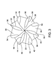
- FIG. 3 is a front view, looking proximally rearward, of the bur head of FIG. 2 ;
- FIG. 4 is a cross sectional view of the bur head of FIG. 2 taken along line 4 - 4 of FIG. 2A ;
- FIG. 5 is a cross sectional view of the bur head of FIG. 2 taken along line 5 - 5 of FIG. 2A ;
- FIG. 6 is a cross sectional view of the bur head of FIG. 2 taken along line 6 - 6 of FIG. 2A ;
- FIGS. 7 and 7A are side views of an alternative bur head constructed in accordance with this invention.
- FIG. 8 is a front view, looking proximally rearward, of the bur head of FIG. 7 ;
- FIG. 9 is a cross sectional view of the bur head of FIG. 7 taken along line 9 - 9 of FIG. 7A ;
- FIG. 10 is a cross sectional view of the bur head of FIG. 7 taken along line 10 - 10 of FIG. 7A ;
- FIG. 11 is a cross sectional view of the bur head of FIG. 7 taken along line 11 - 11 of FIG. 7A ;
- FIG. 12 is a side view of a second alternative bur head constructed in accordance with this invention.
- FIG. 13 is a cross section view of the bur head of FIG. 12 taken along line 13 - 13 ;
- FIG. 14 is a cross section view of the bur head of FIG. 12 taken along line 14 - 14 ;
- FIG. 15 is a cross section view of the bur head of FIG. 12 taken along line 15 - 15 ;
- FIG. 16 is a front view, looking proximally rearward of a third alternative bur constructed in accordance with this invention.
- FIG. 17 is a cross sectional depiction of an alternative bur constructed in accordance with this invention.
- FIG. 18 is an isometric view of an alternative bur of this invention.
- FIG. 19 is a front view of the bur head of FIG. 18 showing respective flute chamfers and cutting edges;
- FIG. 20 is a side view of the bur head of FIG. 18 shaped in accordance with this invention.
- FIG. 21 is a side view of the bur head of FIG. 18 , rotated along the axis of the bur;
- FIG. 22 is a cross sectional view of the bur head of FIG. 18 ;
- FIG. 23 is a side view of a bur head shaped in accordance with this invention, rotated along the axis of the bur, showing the pitch angles of the chamfer surfaces;
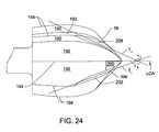
- FIG. 24 is a side view of a bur head shaped in accordance with this invention showing the pitch angles of the chamfer surfaces.
- FIG. 1 illustrates a surgical bur 20 constructed in accordance with this invention.
- Bur 20 has a head 22 that forms the distal end of the bur. (“Distal” it shall be understood, means towards the surgical site to which the bur is applied. “Proximal” means away from the surgical site.)
- Bur head 22 has a distal end tip 23 that is the most forward portion of the bur 20 .
- a shaft 24 extends proximally rearward from the bur head 22 .
- the proximal end of the shaft 24 is provided with coupling features 26 .
- the coupling features 26 are geometric features that facilitate the removable engagement of the shaft 24 to a coupling assembly integral with the rotating shaft of a powered surgical tool with which bur 20 is used (tool not illustrated.)
- the illustrated coupling features 26 are a set of planar faces recessed relative to the outer diameter of the shaft 24 .
- One such geometry is described and illustrated in U.S. Pat. No. 5,888,200, issued 30 Mar. 1999, Multi-Purpose Surgical Tool System, the contents of which is incorporated herein by reference.
- An alternative geometry for coupling features 26 in the form of linearly aligned opposed concave surfaces is illustrated in U.S. Pat. No.
- Bur head 22 is formed with a number of arcuately spaced flutes 30 - 44 .
- Each flute 30 - 44 is formed by a rake surface 50 and a clearance surface 52 .
- Rake surface 50 extends approximately radially from the longitudinal axis of the center core of the bur head 22 .
- the outer perimeter of the center core is generally represented by dashed circle 48 . It should be understood that, as the outer diameter of the bur changes along the length of the bur, the outer diameter of the center core changes.
- Each clearance surface 52 extends generally tangentially from the outer perimeter of the bur head center core.
- each clearance surface 52 extends approximately tangentially away from the base of the rake surface 50 of the flute adjacent the flute formed by the clearance surface.
- the clearance surface 52 of flute 30 extends from the position along the perimeter of the bur head core from which rake surface 50 of flute 32 extends.
- the rake surface 50 and clearance surface 52 that form an individual flute meet to forming a cutting edge 54 .
- the bur cutting edges 54 are the edges of the bur head 22 that perform the cutting when the bur 20 is applied to a surgical surface.
- bur head 22 of this invention flutes 30 , 34 , 38 and 42 are formed so that their rake and clearance surfaces 50 and 52 , respectively, meet to form cutting edges 54 that start at a location relatively close to the distal end tip 23 of the bur head.
- Flutes 32 , 36 , 40 and 44 are formed so that, at the distal ends of the flutes, chamfer surfaces 56 , angled from the rake surfaces 50 , extend between the rake surfaces 50 inwardly towards and to the clearance surfaces 52 .
- Flutes 32 , 36 , 40 and 44 thus have chamfer edges 58 that are the edge surfaces along the interfaces between the clearance surfaces 54 and chamfer adjacent chamfer surfaces 56 .
- chamfer surfaces 56 are formed on flutes 32 , 36 , 40 and 44 to end at the points along the flutes where the flutes have the largest outer diameter relative to the longitudinal center axis of the bur 20 .
- Bur head 22 may be formed by first shaping the head to provide eight (8) identical flutes that extend the full length of the head from the distal end tip to the shaft. Then portions of flutes 32 , 36 , 40 and 44 are selectively removed to form chamfer surfaces 52 . Grinding, electro-discharge machining or laser cutting or other machining methods may be employed to excise the material from flutes 32 , 36 , 40 and 44 to form chamfer surfaces 56 .
- the chamfer edges 58 are closer to this axis than cutting edges 54 . Thus, chamfer edges 58 do not cut the tissue against which the bur head 22 is applied.
- the reduction of the number of cutting edges also reduces the tooth passing frequency at the distal tip of the bur 20 .
- RPM is the revolutions per minute of the bur 20 .
- Variable CE is the number of bur head 22 cutting edges at the position along the bur head at which the bur head is being applied to the tissue to be excised. With bur head 22 of this invention, since there are fewer cutting edges at the distal end of the bur head 22 than at more proximal locations, the tooth passing frequency at the distal end locations is less than the tooth passing frequency at the more proximal locations along the length of the bur head.
- This reduction in distal end tooth passing frequency further reduces the chatter of bur 20 of this invention. This is because a further means of reducing chatter is to operate the bur at a speed so that the tooth passing frequency as closely as possible matches the chatter frequency. This frequency matching assists in the nulling of bur chatter vibration. By reducing the number of flute cutting edges 54 at the distal end of the bur head 22 , it is more likely that when, this end of the bur head is pressed against tissue, the tooth passing frequency will more closely approximate the chatter vibration frequency.
- Bur head 22 of bur 20 has what is referred to as an acorn style head. As depicted by FIGS. 7 , 7 A and 8 - 11 , this invention may be incorporated into bur heads having alternative shapes. Specifically, bur 70 of this version of the invention has what is referred to as a round or spherical head 72 . As seen by reference to FIG. 8 , bur head 72 has flutes 74 - 88 . Each of the flutes 74 - 88 originate at the distal end tip 90 of bur head 72 .
- Each flute 74 - 88 is formed with both a rake surface 94 and a clearance surface 96 .
- Flutes 74 , 78 , 82 and 86 are formed to have cutting edges 98 that, like the flutes themselves, originate at the distal end tip 90 of the bur head.
- Flutes 76 , 80 , 84 and 88 are formed with chamfer surfaces 102 , best seen in FIGS. 8 , 9 and 10 , that start adjacent bur head distal end tip 90 .
- Flutes 76 , 80 , 84 and 88 thus are formed with chamfer edges 104 where each clearance surface 96 meets the associated flute chamfer surface 102 .
- Chamfer surfaces 102 are formed on flutes 76 , 80 , 84 and 88 so that chamfer edges 104 terminate and cutting edges 98 begin at the point where the bur head has its largest outer diameter.
- FIGS. 12-15 illustrate another bur 110 constructed in accordance with this invention.
- Bur 110 has a spherical bur head 112 .
- Bur head 112 is shaped to have ten (10) flutes 114 - 132 best seen in FIG. 15 .
- Each flute 114 - 132 has a rake surface 134 and a clearance surface 136 .
- the rake and clearance surfaces 132 and 134 , respectively, of each flute 114 - 130 meet to form a cutting edge 138 that extends along the length of the flute.
- Bur head 112 of this invention is formed so that the flutes originate from the core of the bur head, represented by dashed circles 139 at different positions along the length of the bur head.
- FIG. 13 illustrates the flutes present at a position adjacent distal end tip 140 of bur head 112 . It can be seen here that only flutes 114 , 118 , 122 , 126 and 130 have emerged from the core of bur head 112 . Thus, clearance surface 136 of flute 130 emerges from the base of rake surface 134 .
- flutes 116 , 120 , 124 , 128 and 132 Extending proximally along the bur head 112 , away from the distal end tip 140 , flutes 116 , 120 , 124 , 128 and 132 start to emerge from the core of bur head 112 as seen in FIG. 14 .
- the rake surfaces 134 of flutes 116 , 120 , 124 , 128 and 132 are shorter in length than the length of rake surfaces 134 of flutes 114 , 118 , 122 , 126 and 130 .
- the cutting edges 138 of flutes 116 , 120 , 124 , 128 and 132 are spaced inwardly of the cutting edges of flutes 114 , 118 , 122 , 126 and 130 . Consequently, at the bur head position of line 14 - 14 of FIG. 12 , cutting edges 138 of flutes 116 , 120 , 124 , 128 and 132 do not contribute to the cutting of the tissue to which
- This version of the invention may be constructed by first forming bur head 112 so that all the flutes extend the full length of the bur head. Then material is removed from flutes 116 , 120 , 124 , 128 and 132 so that the flutes emerge from the bur head core at a position proximal to the distal end tip 140 .
- the means used to form chamfer surfaces 56 are employed to similarly shape flutes 116 , 120 , 124 , 128 and 132 .
- FIG. 16 represents an alternative version of the invention of FIGS. 1-6 .
- bur head 22 a is formed with flutes 30 a - 44 a .
- Flutes 30 a , 34 a , 38 a and 42 a are not formed with chamfered surfaces.
- Flutes 32 a and 40 a are formed with chamfered surfaces 140 .
- Flutes 36 a and 44 a are formed with chamfered surfaces 142 .
- Flutes 32 a and 40 a are formed so that chamfered surfaces 140 extend a first distance proximally rearward along the length of bur head 22 a .
- bur head 22 a of this embodiment of the invention is constructed to have a first set of cutting edges 146 , where the clearance and rake surfaces of flutes 30 a , 34 a , 38 a and 42 a meet, which emerge from the core of the bur head at a first location along the length of the bur head.
- a second set cutting edges 148 where the clearance surfaces and chamfered surfaces 140 of flutes 32 a and 40 a meet, emerges from the core of the bur head at a second location along the length.
- a third set of cutting edges 150 where the clearance surfaces and chamfered surfaces of flutes 36 a and 44 a meet, emerges at a third location along the length of the bur head. This third location is, relative to the distal end tip, spaced further away than the second location.
- FIG. 18 illustrates another surgical bur 160 constructed in accordance with this invention.
- Bur 160 has a head 162 with a distal end tip 163 .
- bur head 162 is formed with a number of arcuately spaced flutes 170 - 184 .
- Each flute 170 - 184 is formed by a rake surface 190 and a clearance surface 192 ( FIG. 22 ).
- Rake surface 190 extends approximately radially from the longitudinal axis of the center core of the bur head 162 . It should be understood that, as the outer diameter of the bur changes along the length of the bur, the outer diameter of the center core changes.
- Each clearance surface 192 extends generally tangentially from the outer perimeter of the bur head center core. More specifically, each clearance surface 192 extends approximately tangentially away from the base of the rake surface 190 of the flute adjacent the flute formed by the clearance surface. Thus, the clearance surface 192 of flute 170 extends from the position along the perimeter of the bur head core from which rake surface 190 of flute 172 extends.
- the rake surface 190 and clearance surface 192 that form an individual flute meet to form a cutting edge 194 .
- the bur cutting edges 194 are the edges of the bur head 162 that perform the cutting when the bur 160 is applied to a surgical surface.
- bur head 162 of this invention has a first pair of two flutes, flutes 170 and 178 , that are formed so that their rake and clearance surfaces 190 and 192 , respectively, meet to form cutting edges 194 at a location that starts relatively close to the bur head distal end tip 163 .
- the area on the surface of the bur immediately around tip 163 can be considered to be a land that is fluteless.
- Flutes 170 and 178 including their cutting edges 194 , emerge from this land. Flutes 170 and 178 are also symmetrical to one another, 180° apart.
- each arcuate section of the bur head between flutes 170 and 178 there are plural additional flutes.
- the second arcuate section contains flutes 180 , 182 and 184 .
- Flutes 172 and 184 are radially adjacent flute 170 .
- Flutes 174 and 182 which are symmetric around the longitudinal center axis of the bur head 162 , are radially spaced from both flutes 170 and 178 .
- These intermediate sets of flutes 172 - 176 and 180 - 184 are formed with chamfers surfaces. These chamfer surfaces effectively “cut-off” the cutting edges of flutes 172 - 36 and 180 - 184 so that their cutting edges 194 emerge from the bur head at locations spaced from the distal end tip of 163 the bur head 162 .
- Each of the chamfer surfaces 196 forms the common distal end face of one of the intermediate flute sets, flute set 172 - 176 and flute set 180 - 186 .
- Each chamfer surface 196 starts at the distal at the perimeter of the land at the distal end tip of the bur head.
- Chamfer surfaces 196 relative to the cutting edges 194 of flutes 170 and 178 are angled closer to the proximal end of the bur shaft.
- the presence of chamfer surfaces 196 means that the cutting edges of flutes 172 - 176 and 180 - 186 emerge from the bur head at distances that are spaced proximal to the distal end tip of the bur head.
- Symmetrically opposed flutes 176 and 184 each have a chamfer surface 200 .
- Each chamfer surface 200 emerges from adjacent the distal end tip of the bur head. Thus each chamfer surface 200 forms an edge with an adjacent chamfer surface 196 .
- Each chamfer surface 200 also abuts the distal end rake surface 190 of one of the flutes 170 or 178 .
- Each chamfer surface 200 has an angle from the longitudinal axis of the bur shaft than the angle of the adjacent chamfer surface 196 .
- Each flute 176 and 184 is formed with a second chamfer surface, chamfer surface 202 .
- Each chamfer surface 202 extends distally rearward from the point where the abutting chamfer surfaces 196 and 200 move apart from each other. Thus, each chamfer surface 202 extends between the rake and clearance surfaces 190 and 192 , respectively, of the associated flute 176 or 184 .
- Each chamfer surface 202 extends proximally rearward along the bur head further than the associated chamfer surface 196 . Owing to the presence of chamfer surfaces 202 , the cutting edges 194 of flutes 176 and 184 emerge from the bur head at position proximal to those where cutting edges 194 of symmetrically opposed flutes 174 and 182 emerge.
- Each flute 172 and 180 is formed with its own chamfer surface 204 .
- Each chamfer surface 204 starts at a point a short distance proximally rearward from the distal end tip of the bur head, at the perimeter of the land.
- Each chamfer surface 204 extends between the rake and clearance surfaces 190 and 192 , respectively, of the associated flute 172 or 180 .
- the distal portion of each chamfer surface 204 intersects the adjacent chamfer surface 196 .
- Each chamfer surface 204 extends rearward along the associated flute 172 or 180 a distance approximately equal to the distance along which chamfer surfaces 202 extend. (These distances being from the distal end tip of the bur head.) Thus, owing to the presence of chamfer surfaces 204 , cutting edges 194 of flutes 172 and 180 emerge from the bur head at the approximately the same position at which the cutting edges 194 of flutes 176 and 184 emerge.
- position is understood to be a location along the longitudinal axis of the bur head 162 relative to the distal end tip.
- Each chamfer surface 196 , 200 , 202 , and 204 is defined by at least two chamfer edges.
- Chamfer surfaces 196 each have two chamfer edges 210 and 212 . Starting at the most proximal location of each chamfer surface 196 , cutting edge chamfer edge 210 starts at the distal end of the cutting edge 194 of flute 174 or 182 and extends generally linearly and distally forward. Chamfer edge 210 then arcuately curves to intersect, or abut, the respective chamfer surface 204 present on flute 172 or 180 . Also starting at the distal end of the cutting edge of flute 174 or 182 is the chamfer edge 212 . Distally forward of this point, edge 212 curves away from edge 210 .
- Edge 210 curves until the edge 210 becomes the boundary between chamfer surface 196 and the adjacent chamfer surface 202 . From this intersection of surface 192 and 202 , edge 212 curves inwardly toward the distal end tip 163 . The section of edge 212 intersects the point where surfaces 196 , 200 and 202 meet. Distally forward of this point, edge forms the boundary between surfaces 196 and 200 .
- Each chamfer surface 200 is defined by two additional edges chamfer edges 214 and 216 .
- Chamfer edge 214 extends from the from the point surfaces 196 , 200 and 202 intersect to the point where surfaces 192 of flute 176 or 184 and surfaces 200 and 202 intersect.
- Chamfer edge 214 is generally linear in shape.
- Chamfer edge 216 forms the outer boundary of chamfer surface 200 . Extends from the intersection of surface 192 of the flute 176 or 184 and surfaces 200 and 202 to the rake surface of the adjacent flute 178 or 170 . Edge 216 is generally linear.
- chamfer edge 202 starts where the clearance surface 192 of flute 174 or 182 and the adjacent chamfer surfaces 196 and 202 meet. From this point, chamfer edge 202 extends generally linearly to the distal end of the cutting edge of the associated with flute 176 or 184 .
- Chamfer edge 220 starts at the proximal end terminus of chamfer edge 216 .
- Chamfer edge 216 initially angles away from edge 218 .
- Edge 218 then curves to and terminates at the point the cutting edge 194 and chamfer edge 218 meet.
- the chamfer surface 204 includes two chamfer edges 222 and 224 .
- Chamfer edge 222 extends proximally from the distal end tip land to the cutting edge of the associated flute 172 or 180 .
- Edge 222 is generally linear.
- Chamfer edge 222 starts at the intersection of the clearance surface 192 of the flute 172 or 180 and the adjacent chamfer surfaces 196 and 202 .
- chamfer edge 224 angles away from edge 222 .
- Edge 224 then curves toward edge 202 .
- Chamfer edge 224 then terminates at the point cutting edge 194 and chamfer edge 202 meet.
- each chamfer surface 196 , 200 , 202 , and 204 is not limited to the described version of the invention. It is purely a product of machining and chamfer surface size whether or not chamfer edges are shared or intersect one another. It is within the scope of the present invention to have chamfer surfaces that share fewer edges. Alternatively, one chamfer surface could extend radially around the entire surface of the bur head 162 in a fashion where small chamfer surfaces extend proximal to the large circumferential chamfer surface.
- each chamfer surface 196 , 200 , 202 , and 204 is shown by reference to a distal extension of this axis that extends forward of bur head tip 163 .
- each chamfer surface is not perfectly flat and is arcuate in nature.
- a tangent line extends from each chamfer surface. Each tangent line intersects either the bur head distal end tip 163 or a distal end extension of the longitudinal center axis (LCA).
- Each chamfer surface 196 , 200 , 202 and 204 can therefore be considered to have a chamfer angle which is the acute angle between the bur head longitudinal center axis and the tangent line of chamfer surface.
- a chamfer angle which is the acute angle between the bur head longitudinal center axis and the tangent line of chamfer surface.
- obtuse angles ⁇ 1 , ⁇ 2 , ⁇ 3 and ⁇ 4 that are complementary to the chamfer angles are called out.
- chamfer surface 196 looks flat, it is indeed curved.
- the radius of chamfer surface 196 is so large in nature that when such a portion of the radius is viewed, the surface visually looks flat. As can be seen in FIG.
- both chamfer surfaces 202 and 204 have the tangent lines that are at the same angle relative to the distal end extension of the longitudinal center axis, of bur head 162 .
- ⁇ 1 equals ⁇ 4 .
- Tangent line T 1 extends tangentially from the chamfer surface 202 intersecting the distal end extension of longitudinal center axis to create angle ⁇ 1 therebetween.
- tangent line T 4 extends tangentially from the surface of chamfer surface 204 intersecting the distal end extension of the longitudinal center axis to create angle ⁇ 4 therebetween. Since ⁇ 1 equals ⁇ 4 , the chamfer surfaces 202 and 204 have the same chamfer angle relative to the distal end extension of the bur head longitudinal center axis.
- FIG. 23 shows the relationship between ⁇ 1 , ⁇ 2 , ⁇ 3 , ⁇ 4 , and ⁇ 5 .
- ⁇ 1 is equivalent to ⁇ 4
- ⁇ 4 is not depicted in FIG 23 .
- each chamfer surface 196 , 200 , and 202 has a respective tangent line T 3 , T 2 and T 1 , respectively, that it is at angle relative to the distal end extension of the bur head longitudinal center axis.
- Each tangent line T 1 , T 2 , and T 3 intersects the distal end extension of the longitudinal center axis at an angle ⁇ 1 , ⁇ 2 and ⁇ 3 , respectively.
- angle ⁇ 1 and, by extension angle ⁇ 4 are greater than ⁇ 2 .
- Angle ⁇ 4 is greater than angle ⁇ 3 ; which in turn is greater than ⁇ 5 .
- angles ⁇ 1 through ⁇ 4 are the obtuse complements to the acute chamfer angles.
- the relationship between the chamfer angles of chamfer surfaces 196 , 200 , 202 and 204 are inverse from the above described angular relationships between the tangent lines and longitudinal center axis of the bur head.
- Chamfer surface 202 and, by extension, chamfer surface 204 have less of a chamfer angle in relationship to the longitudinal center axis of the bur head 162 than chamfer surface 200 .
- Chamfer surface 200 has less of a chamfer angle than chamfer surface 196 .
- the angles of the cutting edges of flutes 170 and 178 are represented by the line T 5 and angle ⁇ 5 .
- Angle ⁇ 5 has the greatest angle at the distal end tip 163 as compared to the angles of each chamfer surface 196 , 200 , 202 , and 204 .
- Angle ⁇ 5 is less than angle ⁇ 1 .
- the angle of the cutting edges of the chamferless flutes 170 and 178 adjacent the distal end tip relative to the longitudinal center axis of the bur head 162 is greater than the chamfer angles of the chamfer surface 196 , 200 , 202 and 204 associated with flutes 172 , 174 , 176 , 180 , 182 and 184 .
- bur head 162 is formed so that the cutting edges 164 are equangularly spaced apart.
- Bur head 162 may be formed by first shaping the head to provide eight (8) identical flutes that extend the full length of the head from the distal end tip to the shaft. Then, portions of flutes 174 and 182 are selectively removed to form chamfer surfaces 196 . Similarly, portions of flutes 172 , 176 , 180 , and 184 are selectively removed to form chamfer surfaces 198 . Grinding, electro-discharge machining or laser cutting or other machining methods may be employed to excise the material from flutes 172 - 36 and 180 - 184 to form their respective chamfer surfaces 196 .
- the bur head 162 may be formed by casting the bur head and grinding down the desired edges to form a cutting edge. By casting the bur head, the chamfer surfaces do not need to be grinded down due to the design of the cast.
- the section of the bur adjacent the distal end tip 163 is the section of the bur head 162 that is pressed against the tissue to be excised. It is at this time the above-described geometry of the bur of this invention becomes advantageous.
- There are a reduced number of cutting edges 194 at the distal end tip 163 two that are symmetrical to one another in the preferred embodiment of an eight flute bur. This reduces the extent to which forces generated as a result of regeneration of waviness excite the bur into chatter vibration.
- the interstitial gap between cutting edges 194 is wider than it would be otherwise. The relatively large size of these gaps minimizes the extent to which excised tissue is trapped in these spaces. This reduces the extent to which tissue entrained in the inter-flute gaps imposes addition vibration-causing force on the bur head 162 .
- a bur head may be arranged so that two or more long length cutting edges are followed by one or more flutes with shorter length cutting edges.
- each pair of adjacent flutes with long length cutting edges may be separated by two or more flutes with shorter length cutting edges.
- one flute may formed to have a cutting edge of a first length and a adjacent short length flute formed to have a cutting edge of a second length.
- a bur head may be constructed to have, in sequence: a flute with a cutting edge that extends from the distal end tip of the head; a flute with chamfer surface 140 ; and a flute with chamfer surface 142 .
- the bur heads of this invention be constructed so that the different length cutting surfaces are symmetrically arranged around the outer perimeter of the bur head.
- a bur head with eight (8) cutting edges may be constructed so that where the individual cutting edges are all present, the edges are spaced 45° apart.
- the first, second, fourth, sixth and seventh flutes are constructed so as to have cutting edges that start adjacent the bur head distal end tip.
- the third, fifth and eighth flutes are constructed to have cutting edges that start at a position spaced proximally to where the first set of flutes start.
- the bur shaft may be provide with a feature that offsets the asymmetric structure of the bur head.
- Such feature may include one or more tabs or fingers that are extend outwardly from the body of the shaft. These tabs are asymmetrically positioned to offset the asymmetrical loading.
- this feature may comprise one or more pins embedded in the shaft that are flush with the shaft. These pins are of different density than the material forming the bur shaft and are again asymmetrically positioned to offset the asymmetric loading.
- FIG. 17 illustrates in cross section an alternative bur head 240 of this invention.
- Bur head 240 is shaped to have a number of arcuately spaced apart flutes 242 - 256 .
- flutes 242 - 256 may extend the complete length of the bur head 240 , from the distal end tip to where the proximal end is joined to the shaft.
- Bur head 240 is further formed so that around the circumference of the head, the flutes 242 - 256 are not equangularly spaced apart; the pitch angles between the adjacent flute pairs are different.
- the bur having this head geometry When the bur having this head geometry is employed, the between two adjacent pairs of flutes, for example between adjacent flutes 244 - 246 and 246 - 248 , the time between when each flute in the pair strikes the tissue is different.
- the time between when flute 246 strikes the bone after it is first struck by flute 244 is less than the time between when flute 248 strikes the bone after it is initially struck by flute 246 .
- This variable periodicity between flute strikes is believed to reduce the extent the bur is forced into chatter-causing vibration.
- the bur head of this invention may be constructed so that not all adjacent pairs of the flutes have pitch angles that vary from each other. Thus, for example with a bur having eight flutes, there may be a first pitch angle between 6 of the adjacent flute pairs and a second pitch angle between two of the adjacent flute pairs
- the disclosed basic bur head shapes are exemplary, not limiting.
- the bur heads may have alternative shapes including barrel head, conical, egg, pear or drum shaped.
- the distal end tips of the bur heads may have profiles different than the curved convex profile of the illustrated embodiments.
- the shorter length cutting edges emerge at the location where the bur heads reach there maximum diameter.
- the shorting length cutting edges are fully emerged at positions along the bur head distal to where the bur head has its larges diameter.
- the flutes with the shorter length cutting edges may have shorter length cutting edges by virtue of the cutting edges terminating at a position along the bur head spaced distally from the locations along which other cutting edges terminate.
- Some versions of the invention may be constructed so that, between flutes with cutting edges that extend the full length of the bur head, there are flutes with cutting edges that start a position proximal to the bur head distal end tip and terminate at a position distal to the proximal terminus of the bur head.
- a single bur may have: a first set of flutes that are relatively long and shaped with relatively long cutting edges; a second set of flutes that are also relatively long and shaped with chamfered surfaces to have short cutting edges; and a third set of one or more flutes that are relatively short in length.
- the shaft structure is not limited to what has been disclosed.
- the bur of this invention may have a tubular shaft.
- the shaft typically has an opening immediately proximal to the bur head.
- the opening functions as a port through which irrigating fluid is discharged or a suction is drawn.
- the coupling feature of the bur is often a hub attached to the proximal open end of the shaft.
- the hub has both geometric features that facilitate the coupling of the bur to a drive handpiece and a port to establish fluid communication to a suction device or from a source of irrigating fluid.
Abstract
Description
TPF=[RPM×No. of CE]/60
Here, RPM is the revolutions per minute of the
Claims (16)
Priority Applications (1)
| Application Number | Priority Date | Filing Date | Title |
|---|---|---|---|
| US13/402,579 US8852222B2 (en) | 2005-07-19 | 2012-02-22 | Surgical bur with anti-chatter flute geometry |
Applications Claiming Priority (6)
| Application Number | Priority Date | Filing Date | Title |
|---|---|---|---|
| US70038405P | 2005-07-19 | 2005-07-19 | |
| PCT/IB2006/002118 WO2007010389A1 (en) | 2005-07-19 | 2006-07-17 | Surgical bur with anti-chatter flute geometry |
| US86673506P | 2006-11-21 | 2006-11-21 | |
| US11/943,303 US20080132929A1 (en) | 2005-07-19 | 2007-11-20 | Surgical bur with anti-chatter flute geometry |
| US12/691,918 US20100121365A1 (en) | 2005-07-19 | 2010-01-22 | Surgical bur with anti-chatter flute geometry |
| US13/402,579 US8852222B2 (en) | 2005-07-19 | 2012-02-22 | Surgical bur with anti-chatter flute geometry |
Related Parent Applications (1)
| Application Number | Title | Priority Date | Filing Date |
|---|---|---|---|
| US12/691,918 Division US20100121365A1 (en) | 2005-07-19 | 2010-01-22 | Surgical bur with anti-chatter flute geometry |
Publications (2)
| Publication Number | Publication Date |
|---|---|
| US20120158028A1 US20120158028A1 (en) | 2012-06-21 |
| US8852222B2 true US8852222B2 (en) | 2014-10-07 |
Family
ID=39476755
Family Applications (3)
| Application Number | Title | Priority Date | Filing Date |
|---|---|---|---|
| US11/943,303 Abandoned US20080132929A1 (en) | 2005-07-19 | 2007-11-20 | Surgical bur with anti-chatter flute geometry |
| US12/691,918 Abandoned US20100121365A1 (en) | 2005-07-19 | 2010-01-22 | Surgical bur with anti-chatter flute geometry |
| US13/402,579 Active US8852222B2 (en) | 2005-07-19 | 2012-02-22 | Surgical bur with anti-chatter flute geometry |
Family Applications Before (2)
| Application Number | Title | Priority Date | Filing Date |
|---|---|---|---|
| US11/943,303 Abandoned US20080132929A1 (en) | 2005-07-19 | 2007-11-20 | Surgical bur with anti-chatter flute geometry |
| US12/691,918 Abandoned US20100121365A1 (en) | 2005-07-19 | 2010-01-22 | Surgical bur with anti-chatter flute geometry |
Country Status (1)
| Country | Link |
|---|---|
| US (3) | US20080132929A1 (en) |
Cited By (11)
| Publication number | Priority date | Publication date | Assignee | Title |
|---|---|---|---|---|
| US20140236156A1 (en) * | 2011-09-16 | 2014-08-21 | CHIRMAT Sàrl | Surgical tool for reaming the diaphyseal canal of long bones |
| US20160287267A1 (en) * | 2015-03-31 | 2016-10-06 | Medtronic Xomed, Inc. | Surgical Burs With Localized Auxiliary Flutes |
| US20180078279A1 (en) * | 2016-09-20 | 2018-03-22 | RELIGN Corporation | Arthroscopic devices and methods |
| WO2019168583A1 (en) * | 2018-02-28 | 2019-09-06 | Medtronic Xomed, Inc. | Surgical bur and related surgical instruments |
| USD882082S1 (en) * | 2018-01-31 | 2020-04-21 | Beijing Smtp Technology Co., Ltd. | Ultrasonic cutter head |
| US11160566B2 (en) * | 2017-02-14 | 2021-11-02 | Depuy Ireland Unlimited Company | Surgical rotational cutting tool and method |
| US11191551B2 (en) | 2013-07-17 | 2021-12-07 | Medtronic Ps Medical, Inc. | Surgical bur with soft tissue protective geometry |
| US11253271B2 (en) | 2014-04-16 | 2022-02-22 | Medtronic Ps Medical, Inc. | Surgical burs with decoupled rake surfaces and corresponding axial and radial rake angles |
| US11406396B2 (en) | 2015-08-31 | 2022-08-09 | Medtronic Ps Medical, Inc. | Surgical burs |
| US11439410B2 (en) | 2012-04-16 | 2022-09-13 | Medtronic Ps Medical, Inc. | Surgical bur with non-paired flutes |
| US11771440B1 (en) | 2022-08-01 | 2023-10-03 | Kevin Ray Myers | Burring devices, systems, and methods |
Families Citing this family (59)
| Publication number | Priority date | Publication date | Assignee | Title |
|---|---|---|---|---|
| US8460298B2 (en) | 2007-08-15 | 2013-06-11 | Stryker Ireland Ltd. | Surgical bur with unequally spaced flutes, flutes with different rake angles and flutes with alternating reliefs |
| US8088163B1 (en) | 2008-02-06 | 2012-01-03 | Kleiner Jeffrey B | Tools and methods for spinal fusion |
| US8062316B2 (en) | 2008-04-23 | 2011-11-22 | Avinger, Inc. | Catheter system and method for boring through blocked vascular passages |
| US8696695B2 (en) | 2009-04-28 | 2014-04-15 | Avinger, Inc. | Guidewire positioning catheter |
| USD853560S1 (en) | 2008-10-09 | 2019-07-09 | Nuvasive, Inc. | Spinal implant insertion device |
| US8864654B2 (en) | 2010-04-20 | 2014-10-21 | Jeffrey B. Kleiner | Method and apparatus for performing retro peritoneal dissection |
| US9717403B2 (en) | 2008-12-05 | 2017-08-01 | Jeffrey B. Kleiner | Method and apparatus for performing retro peritoneal dissection |
| US8366748B2 (en) | 2008-12-05 | 2013-02-05 | Kleiner Jeffrey | Apparatus and method of spinal implant and fusion |
| US9247943B1 (en) | 2009-02-06 | 2016-02-02 | Kleiner Intellectual Property, Llc | Devices and methods for preparing an intervertebral workspace |
| USD656610S1 (en) | 2009-02-06 | 2012-03-27 | Kleiner Jeffrey B | Spinal distraction instrument |
| US8632557B2 (en) * | 2009-05-12 | 2014-01-21 | Cardiovascular Systems, Inc. | Rotational atherectomy device and method to improve abrading efficiency |
| JP6101078B2 (en) | 2009-05-28 | 2017-03-29 | アビンガー・インコーポレイテッドAvinger, Inc. | Optical coherence tomography for bioimaging |
| EP2448502B1 (en) | 2009-07-01 | 2022-04-06 | Avinger, Inc. | Atherectomy catheter with laterally-displaceable tip |
| IN2012DN02281A (en) | 2009-08-26 | 2015-08-21 | Stryker Ireland Ltd | |
| US10973656B2 (en) | 2009-09-18 | 2021-04-13 | Spinal Surgical Strategies, Inc. | Bone graft delivery system and method for using same |
| US9629729B2 (en) | 2009-09-18 | 2017-04-25 | Spinal Surgical Strategies, Llc | Biological delivery system with adaptable fusion cage interface |
| US9173694B2 (en) | 2009-09-18 | 2015-11-03 | Spinal Surgical Strategies, Llc | Fusion cage with combined biological delivery system |
| US10245159B1 (en) | 2009-09-18 | 2019-04-02 | Spinal Surgical Strategies, Llc | Bone graft delivery system and method for using same |
| US9186193B2 (en) | 2009-09-18 | 2015-11-17 | Spinal Surgical Strategies, Llc | Fusion cage with combined biological delivery system |
| USD750249S1 (en) | 2014-10-20 | 2016-02-23 | Spinal Surgical Strategies, Llc | Expandable fusion cage |
| US20170238984A1 (en) | 2009-09-18 | 2017-08-24 | Spinal Surgical Strategies, Llc | Bone graft delivery device with positioning handle |
| US8906028B2 (en) | 2009-09-18 | 2014-12-09 | Spinal Surgical Strategies, Llc | Bone graft delivery device and method of using the same |
| USD723682S1 (en) | 2013-05-03 | 2015-03-03 | Spinal Surgical Strategies, Llc | Bone graft delivery tool |
| US9060877B2 (en) | 2009-09-18 | 2015-06-23 | Spinal Surgical Strategies, Llc | Fusion cage with combined biological delivery system |
| US8685031B2 (en) | 2009-09-18 | 2014-04-01 | Spinal Surgical Strategies, Llc | Bone graft delivery system |
| US20110238099A1 (en) * | 2010-03-24 | 2011-09-29 | Smith & Nephew, Inc. | Arthroscopic Resection Devices |
| JP5782107B2 (en) * | 2010-04-22 | 2015-09-24 | ネオバイオテック カンパニー リミテッド | Drill bit and drill equipped with the same |
| US11382653B2 (en) | 2010-07-01 | 2022-07-12 | Avinger, Inc. | Atherectomy catheter |
| CA2831306C (en) | 2011-03-28 | 2018-11-20 | Avinger, Inc. | Occlusion-crossing devices, imaging, and atherectomy devices |
| US9949754B2 (en) * | 2011-03-28 | 2018-04-24 | Avinger, Inc. | Occlusion-crossing devices |
| US9345406B2 (en) | 2011-11-11 | 2016-05-24 | Avinger, Inc. | Occlusion-crossing devices, atherectomy devices, and imaging |
| US11406412B2 (en) | 2012-05-14 | 2022-08-09 | Avinger, Inc. | Atherectomy catheters with imaging |
| WO2013172974A1 (en) | 2012-05-14 | 2013-11-21 | Avinger, Inc. | Atherectomy catheter drive assemblies |
| EP2849636B1 (en) | 2012-05-14 | 2020-04-22 | Avinger, Inc. | Optical coherence tomography with graded index fiber for biological imaging |
| US9629646B2 (en) | 2012-07-11 | 2017-04-25 | Jens Kather | Curved burr surgical instrument |
| US11284916B2 (en) | 2012-09-06 | 2022-03-29 | Avinger, Inc. | Atherectomy catheters and occlusion crossing devices |
| EP2892443B1 (en) | 2012-09-07 | 2017-08-09 | Stryker European Holdings I, LLC | Surgical bur with plural flutes, a single one of the flutes having a groove that intersects the cutting edge of the flute |
| US20140241819A1 (en) * | 2013-02-27 | 2014-08-28 | C. John Munce | Safety Head Bur |
| EP2967507B1 (en) | 2013-03-15 | 2018-09-05 | Avinger, Inc. | Tissue collection device for catheter |
| US10076349B2 (en) * | 2013-03-15 | 2018-09-18 | Misonix, Inc. | Ultrasonic surgical drill and associated surgical method |
| CN105228514B (en) | 2013-03-15 | 2019-01-22 | 阿维格公司 | Optical pressure sensor component |
| WO2014143064A1 (en) | 2013-03-15 | 2014-09-18 | Avinger, Inc. | Chronic total occlusion crossing devices with imaging |
| EP3019096B1 (en) | 2013-07-08 | 2023-07-05 | Avinger, Inc. | System for identification of elastic lamina to guide interventional therapy |
| EP3082623B1 (en) | 2013-12-20 | 2019-11-13 | Stryker Corporation | Rongeur with cutting implement that is selectively driven by a motor so the cutting implement performs either power assisted or manual cutting of tissue |
| DE102014203448A1 (en) * | 2014-02-26 | 2015-08-27 | Gebr. Brasseler Gmbh & Co. Kg | Method for producing a dental instrument or medical instrument |
| US20150313615A1 (en) * | 2014-05-05 | 2015-11-05 | Daniel R. Jacobson | Bone cleaning tool |
| CN107106190B (en) | 2014-07-08 | 2020-02-28 | 阿维格公司 | High-speed chronic full-closure crossing device |
| CA2992272A1 (en) | 2015-07-13 | 2017-01-19 | Avinger, Inc. | Micro-molded anamorphic reflector lens for image guided therapeutic/diagnostic catheters |
| USD797290S1 (en) | 2015-10-19 | 2017-09-12 | Spinal Surgical Strategies, Llc | Bone graft delivery tool |
| CN108882857A (en) | 2016-01-25 | 2018-11-23 | 阿维格公司 | With the modified OCT image conduit of lag |
| US10335170B2 (en) | 2016-02-12 | 2019-07-02 | Viant As&O Holdings, Llc | Cutting heads for intramedullary reamers |
| JP6959255B2 (en) | 2016-04-01 | 2021-11-02 | アビンガー・インコーポレイテッドAvinger, Inc. | Catheter device for porridge resection |
| US11344327B2 (en) | 2016-06-03 | 2022-05-31 | Avinger, Inc. | Catheter device with detachable distal end |
| EP3478190B1 (en) | 2016-06-30 | 2023-03-15 | Avinger, Inc. | Atherectomy catheter with shapeable distal tip |
| EP3482712A1 (en) * | 2016-07-05 | 2019-05-15 | Brites, Débora | Device with millimetric grading for osteotomy |
| EP3496630B1 (en) | 2016-08-14 | 2024-01-17 | Greatbatch Ltd. | Cutting head for an intramedullary reamer |
| CN107802295A (en) * | 2017-11-28 | 2018-03-16 | 刘建国 | A kind of three concave surfaces spiral cutter head of breast biopsy and rotary-cut probe |
| US10966734B2 (en) * | 2019-05-10 | 2021-04-06 | Warsaw Orthopedic, Inc. | Surgical instrument and method |
| US11793400B2 (en) | 2019-10-18 | 2023-10-24 | Avinger, Inc. | Occlusion-crossing devices |
Citations (30)
| Publication number | Priority date | Publication date | Assignee | Title |
|---|---|---|---|---|
| US372400A (en) * | 1887-11-01 | Dental burring-tool | ||
| US533573A (en) | 1895-02-05 | John d | ||
| GB342881A (en) | 1929-11-05 | 1931-02-12 | Funke Ag Geb | Drill for dental purposes |
| US2360425A (en) | 1941-10-11 | 1944-10-17 | Kinzbach Frank | Milling tool |
| US2411209A (en) | 1944-07-26 | 1946-11-19 | Pure Oil Co | Bit |
| US2795979A (en) | 1954-07-14 | 1957-06-18 | Gen Motors Corp | Chatterless countersink cutter |
| US2847885A (en) | 1956-08-02 | 1958-08-19 | Cleveland Twist Drill Co | Deep hole drill |
| US3337936A (en) | 1967-02-13 | 1967-08-29 | David B Curry | Milling tool for milling or cutting objects in a well bore |
| US3409965A (en) | 1966-06-07 | 1968-11-12 | Universal American Corp | Tipped ball end cutter |
| DE3032493A1 (en) | 1980-08-28 | 1982-04-08 | Etablissement Dentaire Ivoclar, Schaan | Milling tool with shank for clamping in rotating chuck - has integral cutting portions of equal or reducing diameters at both ends |
| US4934881A (en) | 1988-07-11 | 1990-06-19 | Mitsubishi Metal Corporation | Ball end mill |
| US5122134A (en) | 1990-02-02 | 1992-06-16 | Pfizer Hospital Products Group, Inc. | Surgical reamer |
| US5209612A (en) | 1992-03-27 | 1993-05-11 | The Budd Company | Cutting tool |
| US5312208A (en) * | 1992-04-28 | 1994-05-17 | Fuji Seiko Corporation | Burnishing drill |
| US5618293A (en) | 1995-06-06 | 1997-04-08 | Smith & Nephews Dyonics, Inc. | Surgical instrument |
| US5626444A (en) | 1994-03-09 | 1997-05-06 | Campian; Jonathon | Rotary cutting tool |
| US5725338A (en) | 1993-12-08 | 1998-03-10 | Societe Nationale D'etude Et De Construction De Moteurs D'aviation "Snecma" | Drill bit having a hemispherical head with an evolutive cut |
| US5759185A (en) | 1994-10-24 | 1998-06-02 | Smith & Nephew, Inc. | Surgical instrument |
| US5833402A (en) | 1994-05-19 | 1998-11-10 | Societe Europeenne De Propulsion | Removable copying cutter |
| DE19718938C1 (en) | 1997-05-05 | 1998-11-19 | Brasseler Gmbh & Co Kg Geb | Dental router tool |
| US5888200A (en) | 1996-08-02 | 1999-03-30 | Stryker Corporation | Multi-purpose surgical tool system |
| US5913867A (en) | 1996-12-23 | 1999-06-22 | Smith & Nephew, Inc. | Surgical instrument |
| DE19826276C1 (en) | 1998-06-12 | 1999-11-04 | Brasseler Gmbh & Co Kg Geb | Dental drill bit |
| US6158304A (en) | 1993-11-01 | 2000-12-12 | Smith International, Inc. | Process for forming a center cutting end mill |
| US6257889B1 (en) | 1999-03-25 | 2001-07-10 | Temple University - Of The Commonwealth System Of Higher Education | Dental bur and method |
| US6258093B1 (en) | 1999-02-01 | 2001-07-10 | Garland U. Edwards | Surgical reamer cutter |
| US6347941B1 (en) | 2001-02-23 | 2002-02-19 | Temple University Of The Commonwealth System Of Higher Education | Partial dentin caries excavator |
| US6562055B2 (en) | 2000-02-18 | 2003-05-13 | Stryker Corporation | Cutting attachment for a surgical handpiece designed to be selectively coupled to the handpiece |
| US20040197741A1 (en) | 2000-12-01 | 2004-10-07 | Mo R&D, Inc. | Method of finishing resin-based dental restorations |
| US20050283160A1 (en) | 2004-03-25 | 2005-12-22 | Brad Knisely | Bidirectional reaming cutter |
-
2007
- 2007-11-20 US US11/943,303 patent/US20080132929A1/en not_active Abandoned
-
2010
- 2010-01-22 US US12/691,918 patent/US20100121365A1/en not_active Abandoned
-
2012
- 2012-02-22 US US13/402,579 patent/US8852222B2/en active Active
Patent Citations (30)
| Publication number | Priority date | Publication date | Assignee | Title |
|---|---|---|---|---|
| US372400A (en) * | 1887-11-01 | Dental burring-tool | ||
| US533573A (en) | 1895-02-05 | John d | ||
| GB342881A (en) | 1929-11-05 | 1931-02-12 | Funke Ag Geb | Drill for dental purposes |
| US2360425A (en) | 1941-10-11 | 1944-10-17 | Kinzbach Frank | Milling tool |
| US2411209A (en) | 1944-07-26 | 1946-11-19 | Pure Oil Co | Bit |
| US2795979A (en) | 1954-07-14 | 1957-06-18 | Gen Motors Corp | Chatterless countersink cutter |
| US2847885A (en) | 1956-08-02 | 1958-08-19 | Cleveland Twist Drill Co | Deep hole drill |
| US3409965A (en) | 1966-06-07 | 1968-11-12 | Universal American Corp | Tipped ball end cutter |
| US3337936A (en) | 1967-02-13 | 1967-08-29 | David B Curry | Milling tool for milling or cutting objects in a well bore |
| DE3032493A1 (en) | 1980-08-28 | 1982-04-08 | Etablissement Dentaire Ivoclar, Schaan | Milling tool with shank for clamping in rotating chuck - has integral cutting portions of equal or reducing diameters at both ends |
| US4934881A (en) | 1988-07-11 | 1990-06-19 | Mitsubishi Metal Corporation | Ball end mill |
| US5122134A (en) | 1990-02-02 | 1992-06-16 | Pfizer Hospital Products Group, Inc. | Surgical reamer |
| US5209612A (en) | 1992-03-27 | 1993-05-11 | The Budd Company | Cutting tool |
| US5312208A (en) * | 1992-04-28 | 1994-05-17 | Fuji Seiko Corporation | Burnishing drill |
| US6158304A (en) | 1993-11-01 | 2000-12-12 | Smith International, Inc. | Process for forming a center cutting end mill |
| US5725338A (en) | 1993-12-08 | 1998-03-10 | Societe Nationale D'etude Et De Construction De Moteurs D'aviation "Snecma" | Drill bit having a hemispherical head with an evolutive cut |
| US5626444A (en) | 1994-03-09 | 1997-05-06 | Campian; Jonathon | Rotary cutting tool |
| US5833402A (en) | 1994-05-19 | 1998-11-10 | Societe Europeenne De Propulsion | Removable copying cutter |
| US5759185A (en) | 1994-10-24 | 1998-06-02 | Smith & Nephew, Inc. | Surgical instrument |
| US5618293A (en) | 1995-06-06 | 1997-04-08 | Smith & Nephews Dyonics, Inc. | Surgical instrument |
| US5888200A (en) | 1996-08-02 | 1999-03-30 | Stryker Corporation | Multi-purpose surgical tool system |
| US5913867A (en) | 1996-12-23 | 1999-06-22 | Smith & Nephew, Inc. | Surgical instrument |
| DE19718938C1 (en) | 1997-05-05 | 1998-11-19 | Brasseler Gmbh & Co Kg Geb | Dental router tool |
| DE19826276C1 (en) | 1998-06-12 | 1999-11-04 | Brasseler Gmbh & Co Kg Geb | Dental drill bit |
| US6258093B1 (en) | 1999-02-01 | 2001-07-10 | Garland U. Edwards | Surgical reamer cutter |
| US6257889B1 (en) | 1999-03-25 | 2001-07-10 | Temple University - Of The Commonwealth System Of Higher Education | Dental bur and method |
| US6562055B2 (en) | 2000-02-18 | 2003-05-13 | Stryker Corporation | Cutting attachment for a surgical handpiece designed to be selectively coupled to the handpiece |
| US20040197741A1 (en) | 2000-12-01 | 2004-10-07 | Mo R&D, Inc. | Method of finishing resin-based dental restorations |
| US6347941B1 (en) | 2001-02-23 | 2002-02-19 | Temple University Of The Commonwealth System Of Higher Education | Partial dentin caries excavator |
| US20050283160A1 (en) | 2004-03-25 | 2005-12-22 | Brad Knisely | Bidirectional reaming cutter |
Non-Patent Citations (1)
| Title |
|---|
| "EPO ISA Search Report and Written Opinion" for PCT App. No. PCT/IB2006/002118, Nov. 2006. |
Cited By (18)
| Publication number | Priority date | Publication date | Assignee | Title |
|---|---|---|---|---|
| US20140236156A1 (en) * | 2011-09-16 | 2014-08-21 | CHIRMAT Sàrl | Surgical tool for reaming the diaphyseal canal of long bones |
| US11439410B2 (en) | 2012-04-16 | 2022-09-13 | Medtronic Ps Medical, Inc. | Surgical bur with non-paired flutes |
| US11191551B2 (en) | 2013-07-17 | 2021-12-07 | Medtronic Ps Medical, Inc. | Surgical bur with soft tissue protective geometry |
| US11253271B2 (en) | 2014-04-16 | 2022-02-22 | Medtronic Ps Medical, Inc. | Surgical burs with decoupled rake surfaces and corresponding axial and radial rake angles |
| US10786266B2 (en) * | 2015-03-31 | 2020-09-29 | Medtronic Xomed, Inc. | Surgical burs with localized auxiliary flutes |
| US20210000488A1 (en) * | 2015-03-31 | 2021-01-07 | Medtronic Xomed, Inc. | Surgical Burs With Localized Auxiliary Flutes |
| US20160287267A1 (en) * | 2015-03-31 | 2016-10-06 | Medtronic Xomed, Inc. | Surgical Burs With Localized Auxiliary Flutes |
| US20180242986A1 (en) * | 2015-03-31 | 2018-08-30 | Medtronic Xomed, Inc. | Surgical Burs With Localized Auxiliary Flutes |
| US9955981B2 (en) * | 2015-03-31 | 2018-05-01 | Medtronic Xomed, Inc | Surgical burs with localized auxiliary flutes |
| US11406396B2 (en) | 2015-08-31 | 2022-08-09 | Medtronic Ps Medical, Inc. | Surgical burs |
| US10028767B2 (en) * | 2016-09-20 | 2018-07-24 | RELIGN Corporation | Arthroscopic devices and methods |
| US10849648B2 (en) | 2016-09-20 | 2020-12-01 | RELIGN Corporation | Arthroscopic devices and methods |
| US20180078279A1 (en) * | 2016-09-20 | 2018-03-22 | RELIGN Corporation | Arthroscopic devices and methods |
| US11576699B2 (en) | 2016-09-20 | 2023-02-14 | RELIGN Corporation | Arthroscopic devices and methods |
| US11160566B2 (en) * | 2017-02-14 | 2021-11-02 | Depuy Ireland Unlimited Company | Surgical rotational cutting tool and method |
| USD882082S1 (en) * | 2018-01-31 | 2020-04-21 | Beijing Smtp Technology Co., Ltd. | Ultrasonic cutter head |
| WO2019168583A1 (en) * | 2018-02-28 | 2019-09-06 | Medtronic Xomed, Inc. | Surgical bur and related surgical instruments |
| US11771440B1 (en) | 2022-08-01 | 2023-10-03 | Kevin Ray Myers | Burring devices, systems, and methods |
Also Published As
| Publication number | Publication date |
|---|---|
| US20120158028A1 (en) | 2012-06-21 |
| US20080132929A1 (en) | 2008-06-05 |
| US20100121365A1 (en) | 2010-05-13 |
Similar Documents
| Publication | Publication Date | Title |
|---|---|---|
| US8852222B2 (en) | Surgical bur with anti-chatter flute geometry | |
| EP1903954B1 (en) | Surgical bur with anti-chatter flute geometry | |
| US9179923B2 (en) | Ribbed surgical bur | |
| EP2916750B1 (en) | Tissue-removing catheter with rotatable cutter | |
| US5122134A (en) | Surgical reamer | |
| JP5499180B2 (en) | Method and apparatus for cutting tissue | |
| US5913867A (en) | Surgical instrument | |
| WO2008061711A2 (en) | Surgical bur with anti-chatter flute geometry including a pair of symmetric flutes that emerge from the distal end tip of the bur head | |
| EP1690504A1 (en) | Arthroscopic shaver and method of manufacturing same | |
| JP2005501648A (en) | Flexible inner tubular member and rotating tissue cutting instrument having flexible inner tubular member | |
| JP2015527153A (en) | Surgical bar with a blade groove having a rake face that varies both in helix angle and rake angle | |
| US20220387050A1 (en) | Surgical milling cutter with improved chip removal |
Legal Events
| Date | Code | Title | Description |
|---|---|---|---|
| STCF | Information on status: patent grant |
Free format text: PATENTED CASE |
|
| AS | Assignment |
Owner name: STRYKER EUROPEAN HOLDINGS I, LLC, MICHIGAN Free format text: NUNC PRO TUNC ASSIGNMENT;ASSIGNOR:STRYKER MEDTECH LIMITED;REEL/FRAME:037153/0241 Effective date: 20151013 Owner name: STRYKER MEDTECH LIMITED, MALTA Free format text: NUNC PRO TUNC ASSIGNMENT;ASSIGNOR:STRYKER IRELAND LIMITED;REEL/FRAME:037152/0946 Effective date: 20151013 |
|
| AS | Assignment |
Owner name: STRYKER EUROPEAN HOLDINGS I, LLC, MICHIGAN Free format text: CORRECTIVE ASSIGNMENT TO CORRECT THE INCORRECT LISTED SERIAL NOS. 09/905,670 AND 07/092,079 PREVIOUSLY RECORDED AT REEL: 037153 FRAME: 0241. ASSIGNOR(S) HEREBY CONFIRMS THE NUNC PRO TUNC ASSIGNMENT EFFECTIVE DATE 9/29/2014;ASSIGNOR:STRYKER MEDTECH LIMITED;REEL/FRAME:038043/0011 Effective date: 20151013 |
|
| MAFP | Maintenance fee payment |
Free format text: PAYMENT OF MAINTENANCE FEE, 4TH YEAR, LARGE ENTITY (ORIGINAL EVENT CODE: M1551) Year of fee payment: 4 |
|
| AS | Assignment |
Owner name: STRYKER IRELAND LTD., IRELAND Free format text: ASSIGNMENT OF ASSIGNORS INTEREST;ASSIGNORS:O'SULLIVAN, DENIS F.;O'DONOGHUE, DENIS;SIGNING DATES FROM 20080207 TO 20080212;REEL/FRAME:051549/0683 |
|
| AS | Assignment |
Owner name: STRYKER EUROPEAN OPERATIONS HOLDINGS LLC, MICHIGAN Free format text: CHANGE OF NAME;ASSIGNOR:STRYKER EUROPEAN HOLDINGS III, LLC;REEL/FRAME:052860/0716 Effective date: 20190226 Owner name: STRYKER EUROPEAN HOLDINGS III, LLC, DELAWARE Free format text: NUNC PRO TUNC ASSIGNMENT;ASSIGNOR:STRYKER EUROPEAN HOLDINGS I, LLC;REEL/FRAME:052861/0001 Effective date: 20200519 |
|
| MAFP | Maintenance fee payment |
Free format text: PAYMENT OF MAINTENANCE FEE, 8TH YEAR, LARGE ENTITY (ORIGINAL EVENT CODE: M1552); ENTITY STATUS OF PATENT OWNER: LARGE ENTITY Year of fee payment: 8 |