US8852702B2 - Label - Google Patents
Label Download PDFInfo
- Publication number
- US8852702B2 US8852702B2 US13/287,433 US201113287433A US8852702B2 US 8852702 B2 US8852702 B2 US 8852702B2 US 201113287433 A US201113287433 A US 201113287433A US 8852702 B2 US8852702 B2 US 8852702B2
- Authority
- US
- United States
- Prior art keywords
- label
- label body
- cut portions
- width direction
- magnetic materials
- Prior art date
- Legal status (The legal status is an assumption and is not a legal conclusion. Google has not performed a legal analysis and makes no representation as to the accuracy of the status listed.)
- Expired - Fee Related, expires
Links
Images


Classifications
-
- G—PHYSICS
- G09—EDUCATION; CRYPTOGRAPHY; DISPLAY; ADVERTISING; SEALS
- G09F—DISPLAYING; ADVERTISING; SIGNS; LABELS OR NAME-PLATES; SEALS
- G09F3/00—Labels, tag tickets, or similar identification or indication means; Seals; Postage or like stamps
- G09F3/02—Forms or constructions
-
- G—PHYSICS
- G09—EDUCATION; CRYPTOGRAPHY; DISPLAY; ADVERTISING; SEALS
- G09F—DISPLAYING; ADVERTISING; SIGNS; LABELS OR NAME-PLATES; SEALS
- G09F3/00—Labels, tag tickets, or similar identification or indication means; Seals; Postage or like stamps
- G09F3/08—Fastening or securing by means not forming part of the material of the label itself
- G09F3/10—Fastening or securing by means not forming part of the material of the label itself by an adhesive layer
-
- G—PHYSICS
- G09—EDUCATION; CRYPTOGRAPHY; DISPLAY; ADVERTISING; SEALS
- G09F—DISPLAYING; ADVERTISING; SIGNS; LABELS OR NAME-PLATES; SEALS
- G09F3/00—Labels, tag tickets, or similar identification or indication means; Seals; Postage or like stamps
- G09F3/02—Forms or constructions
- G09F2003/0264—Shapes or borders
- G09F2003/0267—Shapes or borders die cut
-
- Y—GENERAL TAGGING OF NEW TECHNOLOGICAL DEVELOPMENTS; GENERAL TAGGING OF CROSS-SECTIONAL TECHNOLOGIES SPANNING OVER SEVERAL SECTIONS OF THE IPC; TECHNICAL SUBJECTS COVERED BY FORMER USPC CROSS-REFERENCE ART COLLECTIONS [XRACs] AND DIGESTS
- Y10—TECHNICAL SUBJECTS COVERED BY FORMER USPC
- Y10S—TECHNICAL SUBJECTS COVERED BY FORMER USPC CROSS-REFERENCE ART COLLECTIONS [XRACs] AND DIGESTS
- Y10S428/00—Stock material or miscellaneous articles
- Y10S428/90—Magnetic feature
-
- Y—GENERAL TAGGING OF NEW TECHNOLOGICAL DEVELOPMENTS; GENERAL TAGGING OF CROSS-SECTIONAL TECHNOLOGIES SPANNING OVER SEVERAL SECTIONS OF THE IPC; TECHNICAL SUBJECTS COVERED BY FORMER USPC CROSS-REFERENCE ART COLLECTIONS [XRACs] AND DIGESTS
- Y10—TECHNICAL SUBJECTS COVERED BY FORMER USPC
- Y10T—TECHNICAL SUBJECTS COVERED BY FORMER US CLASSIFICATION
- Y10T428/00—Stock material or miscellaneous articles
- Y10T428/14—Layer or component removable to expose adhesive
-
- Y—GENERAL TAGGING OF NEW TECHNOLOGICAL DEVELOPMENTS; GENERAL TAGGING OF CROSS-SECTIONAL TECHNOLOGIES SPANNING OVER SEVERAL SECTIONS OF THE IPC; TECHNICAL SUBJECTS COVERED BY FORMER USPC CROSS-REFERENCE ART COLLECTIONS [XRACs] AND DIGESTS
- Y10—TECHNICAL SUBJECTS COVERED BY FORMER USPC
- Y10T—TECHNICAL SUBJECTS COVERED BY FORMER US CLASSIFICATION
- Y10T428/00—Stock material or miscellaneous articles
- Y10T428/15—Sheet, web, or layer weakened to permit separation through thickness
-
- Y—GENERAL TAGGING OF NEW TECHNOLOGICAL DEVELOPMENTS; GENERAL TAGGING OF CROSS-SECTIONAL TECHNOLOGIES SPANNING OVER SEVERAL SECTIONS OF THE IPC; TECHNICAL SUBJECTS COVERED BY FORMER USPC CROSS-REFERENCE ART COLLECTIONS [XRACs] AND DIGESTS
- Y10—TECHNICAL SUBJECTS COVERED BY FORMER USPC
- Y10T—TECHNICAL SUBJECTS COVERED BY FORMER US CLASSIFICATION
- Y10T428/00—Stock material or miscellaneous articles
- Y10T428/32—Composite [nonstructural laminate] of inorganic material having metal-compound-containing layer and having defined magnetic layer
Definitions
- the present invention relates to a label.
- a label including: a belt-like label body having a base and an adhesion layer provided on one surface of the base; a linear magnetic material arranged in the label body along a longitudinal direction of the label body; and plural cut portions provided by cutting the label body and the magnetic material along a width direction of the label body except for a portion of the label body in the width direction, and provided at intervals in the longitudinal direction of the label body.
- FIG. 1 is a perspective view showing a label related to a first exemplary embodiment
- FIG. 2 is a plane view showing the label related to the first exemplary embodiment
- FIG. 3 is a cross-sectional view showing a label related to the first exemplary embodiment
- FIG. 4 is a plane view showing another label related to the first exemplary embodiment
- FIGS. 5A to 5C are schematic views for describing a large Barkhausen effect
- FIG. 6 is a plane view showing a label related to a second exemplary embodiment
- FIGS. 7A and 7B are cross-sectional views showing the label related to the second exemplary embodiment
- FIG. 8 is a plane view showing still another label related to the first exemplary embodiment
- FIG. 9 is a plane view showing still another label related to the first exemplary embodiment.
- FIG. 10 is a plane view showing still another label related to the first exemplary embodiment
- FIG. 11 is a plane view showing still another label related to the first exemplary embodiment.
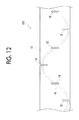
- FIG. 12 is a plane view showing still another label related to the first exemplary embodiment.
- FIG. 1 is a perspective view showing a label related to a first exemplary embodiment.
- FIG. 2 is a plane view showing the label related to the first exemplary embodiment.
- FIG. 3 is a cross-sectional view showing the label related to the first exemplary embodiment.
- FIG. 3 is equivalent to the A-A cross-sectional view of FIGS. 1 and 2 .
- a label 101 related to a first exemplary embodiment includes, for example, a belt-like label body 10 , and a linear magnetic material 16 (hereinafter referred to as a magnetic wire 16 ) arranged in the label body 10 along the longitudinal direction of the label body 10 .
- a linear magnetic material 16 hereinafter referred to as a magnetic wire 16
- the label 101 has a cut portion 18 provided by cutting the label body 10 and the magnetic wire 16 .
- the label 101 related to the present exemplary embodiment shows, for example, a roll form in which the label 101 is wound around a core body 101 A in the shape of a roll
- the label is not limited thereto, and may have a sheet-like form that is cut out to a target length.
- the label body 10 related to the present exemplary embodiment has, for example, a base 12 and an adhesion layer 14 provided on one surface of the base 12 .
- the cut portion 18 is provided so as to cut the label body 10 and the magnetic wire 16 along the width direction of the label body 10 , except for both ends of the label body 10 in the width direction (that is, a direction that crosses the longitudinal direction of the label body 10 or the arrangement direction of the magnetic wire 16 ).
- the cut portion 18 is provided so as to cut the label body 10 and the magnetic wire 16 at the central portion of the label body 10 in the width direction, for example, along the width direction of the label body 10 .
- the length (the length of the label body 10 along the width direction) of the cut portion 18 may be 0.1 ⁇ L or more and 0.8 ⁇ L or less (desirably 0.2 ⁇ L ⁇ m or more and 0.7 ⁇ L ⁇ m or less), for example, when the width of the label body 10 is L (mm).
- Such cut portions 18 are plurally provided at intervals in the longitudinal direction (that is, the direction that crosses the arrangement direction of the magnetic wire 16 ) of the label body 10 .
- the interval between the cut portions 18 includes, for example, a range of 15 mm or more and 400 mm or less (desirably 25 mm or more and 300 mm or less), and is determined according to the size (length along the longitudinal direction of the label 101 ) of a label 101 to adhere when adhering to an adhesion target.
- the cut portion 18 is provided, for example, at a position where the label 101 is cut out when adhering to an adhesion target.
- the interval between the cut portions 18 may be constant.
- the base 12 related to the present exemplary embodiment will be described.
- the base 12 includes, for example, a base made of resin and a base made of paper.
- the base 12 may have optical transparency or may have optical non-transparency.
- the optical transparency means transmitting 60% or more of visible light.
- the magnetic wire 16 included in the label body 10 is made visible intentionally and positively, and when the base 12 has the non-transparency, there is an advantage that the magnetic wire 16 included in the label body 10 is not easily made visible.
- the base 12 made of resin includes, for example, bases configured to include polyester resin, polyethylene terephthalate resin, polystyrene resin, polyolefin resin, polypropylene resin, and the like.
- the base 12 made of paper includes, for example, plain paper, kraft paper, recycled paper, coated paper, and the like.
- the basis weight of the base 12 made of paper includes, for example, a range of 50 g/m 2 or more and 180 g/m 2 or less.
- An internal additive may be blended with the base 12 made of paper.
- the internal additive to blend is not particularly limited, and includes, for example, organic and inorganic particles.
- various chemicals such as a sizing agent, may be internally added or externally added to the base 12 made of paper.
- the type of the sizing agent includes, sizing agents, such as a rosin-based sizing agent, a synthetic sizing agent, a petroleum-resin-based sizing agent, and a neutral sizing agent.
- sizing agents such as a rosin-based sizing agent, a synthetic sizing agent, a petroleum-resin-based sizing agent, and a neutral sizing agent.
- a paper strong agent may be internally added or externally added to the base 12 made of paper.
- the base 12 made of paper may use various agents, such as a dye and a pH adjuster, which are blended with usual paper medium, besides the above.
- the adhesion layer 14 related to the present exemplary embodiment will be described.
- the adhesion layer 14 is composed of adhesive.
- the adhesive includes, for example, various kinds of adhesives, such as an acrylic adhesive, a polyester adhesive, an urethane adhesive, a silicone adhesive, a crude-rubber adhesive, and a synthetic-rubber adhesive.
- the thickness of the adhesion layer 14 includes, for example, a range of 2 ⁇ m or more and 40 ⁇ m or less. Additionally, the amount of coating of the adhesion layer 14 (amount in terms of solid content) includes, for example, a range of 5 g/m 2 or more and 40 g/m 2 or less per surface of the base 12 .
- the magnetic wire 16 related to the present exemplary embodiment will be described.
- the magnetic wire 16 for example, is linearly arranged in the label body 10 along the longitudinal direction of the label body 10 , in a shape seen from the thickness direction of the label body 10 (the direction orthogonal to the principal surface of the label body 10 ) (refer to FIG. 2 ).
- the magnetic wire 16 is arranged so as to be buried in the adhesion layer 14 .
- the magnetic wire 16 may be arranged at the central portion of the adhesion layer 14 in the thickness direction, or is located on the base 12 side or on the side opposite to the base 12 .
- the magnetic wire 16 shows a form that is located on the base 12 side and is buried in the adhesion layer 14 .
- the magnetic wire 16 is not limited to the linearly arranged form, and, for example, as shown in FIG. 4 , is arranged in a bent or curved manner (a form which is arranged in a curved manner is shown in FIG. 4 ) along the longitudinal direction of the label body 10 , in a shape seen from the thickness direction of the label body 10 (the direction orthogonal to the principal surface of the label body 10 ).
- a cycle in which the magnetic wire is bent or curved may be regular or may be irregular.
- the magnetic wire 16 may be arranged in a bent or curved manner such that the positions (the positions of the label body 10 in the width direction) of the magnetic wire 16 in adjacent cut portions 18 among the plural cut portions 18 provided in the label body 10 is different.
- the magnetic wire 16 are cut.
- edge nicking of the cut member for example, cutter or the like
- FIGS. 5A to 5C are schematic views for describing the large Barkhausen effect.
- the large Barkhausen effect is a phenomenon in which steep magnetization reversal occurs when B-H (magnetic flux density-magnetic field) characteristics shown in FIG. 5A , that is, the hysteresis loop is oblong, and a material having a comparatively small coercive force (Hc), for example, an amorphous magnetic material constituted by Co—Fe—Ni—B—Si, is placed in an alternating magnetic field.
- B-H magnetic flux density-magnetic field
- a pulse current shown at the lower level of FIG. 5B flows into the detection coil.
- the alternating current induced by the alternating magnetic field also flows to the current that flows to the detection coil, and the pulse current is detected as being overlapped on this alternating current. Additionally, when a matter including the plural magnetic materials is placed in the alternating magnetic field, plural pulse currents are overlapped on each other, and a current shown in FIG. 5C is detected.
- a carrying-out prohibition or restriction state is given by adhering the label 101 including the magnetic wire 16 to the adhesion target in order to detect an electric signal (for example, a pulse signal shown in FIGS. 5A to 5C ) generated in the magnetic wire 16 using a detecting device.
- an electric signal for example, a pulse signal shown in FIGS. 5A to 5C
- the magnetic wire 16 generally includes permanent magnets, for example, a permanent magnet having a rare-earth-based neodium (Nd)-iron (Fe)-boron (B) as principal components, a permanent magnet having samarium (Sm)-cobalt (Co) as principal components, a permanent magnet having an alnico-based aluminum (Al)-nickel (Ni)-cobalt (Co) as principal components, a permanent magnet having a ferrite-based barium(Ba) or strontium(Sr) and ferrous oxide (Fe 2 O 3 ) as principal components, other soft magnetic materials, oxide soft magnetic materials, and the like.
- a permanent magnet having a rare-earth-based neodium (Nd)-iron (Fe)-boron (B) as principal components
- a permanent magnet having samarium (Sm)-cobalt (Co) as principal components
- the shape of the magnetic wire 16 is not particularly limited if the magnetic wire has an oblong shape that is suitable for generating a large Barkhausen effect, a predetermined length is required with respect to the cross-sectional area in order to cause a large Barkhausen effect.
- the magnetic wire 16 is a linear magnetic material.
- the linear shape is a concept including shapes provided such that circular, rectangular, and other shapes as cross-sectional shapes (shapes that are cut along a direction that crosses the longitudinal direction of a magnetic wire body 14 ) extend in the shape of a straight line or in the shape of a curve.
- the diameter of the magnetic wire 16 may be equal to or more than 10 ⁇ m.
- the length of the magnetic wire 16 may be equal to or more than 10 mm.
- the surface of the magnetic wire 16 may be subjected to insulating processing with insulating materials, such as ceramics or glass, for example, in order to increase the output of a pulse signal.
- a hidden layer (not shown) may be provided between the base 12 and the adhesion layer 14 .
- the hidden layer By providing the hidden layer, the magnetic wire 16 buried in the adhesion layer 14 is does not easily become visible.
- the hidden layer is not particularly limited if the hidden layer has a hiding property (shielding property).
- the hidden layer is formed by, for example, a method of coating and printing an opaquer on the rear surface (surface on the adhesion layer 14 side) of the base 12 , a method of mixing a pigment or the like with an adhesive to applying the resulting mixture, or the like.
- a pigment or the like may be mixed with an adhesive that constitutes the adhesion layer 14 , thereby giving a hiding function to the adhesion layer 14 to use the adhesion layer 14 as an adhesive shield layer.
- the thickness of the shield layer may be, for example, 2 ⁇ m or more and 40 ⁇ m or less.
- the label 101 related to the present exemplary embodiment described above is adhered to an object to be adhered after being provided by cutting out to a predetermined size (length along the longitudinal direction of the label 101 ), for example, using a label cutter.
- the hardness of the metal magnetic wire 16 is high compared to the base 12 and the adhesion layer 14 made of paper or resin. Therefore, poor cutting of the magnetic wire 16 may occur.
- the cut portion 18 provided by cutting out the label body 10 and the magnetic wire 16 is provided in advance. Since the cut portion 18 is provided except for a portion (both ends in the present exemplary embodiment) of the label body 10 in the width direction, the label 101 does not separate with the cut portion 18 as a border.
- the label 101 when the label 101 is adhered to an object to be adhered, the label 101 is cut out along the cut portion 18 in which the magnetic wire 16 is cut in advance, whereby poor cutting of the magnetic wire 16 by the label cutter is suppressed.
- edge nicking of the label cutter is also suppressed.
- the cut portion 18 is provided except for both ends of the label body 10 in the width direction, whereby the belt-like label 101 is brought into a connected state at both the ends. Thereby, winding into a roll is stably realized.
- the cut portion 18 is provided by cutting the magnetic wire 16 except for both ends of the label body 10 in the width direction
- the invention is not limited thereto, and any arbitrary forms in which the cut portion 18 is provided except for a portion of the label body 10 in the width direction may be adopted.
- the label 101 related to the first exemplary embodiment may have a form in which the cut portion 18 is provided according to the arrangement position of the magnetic wire 16 of the label body 10 . That is, a form in which the cut portion 18 that divides the whole label body 10 is provided only near the arrangement position of the magnetic wire 16 in the label body 10 (that is, for example, a form in which the cut portion 18 is provided only near the arrangement position of the magnetic wire 16 in the label body 10 according to the arrangement position and of the magnetic wire 16 and the number of magnetic wires in the width direction of the label body 10 . Thereby, poor cutting of the magnetic wire 16 by the label cutter is suppressed similarly to the case where the cut portion is provided except for both the ends.
- the label 101 in which the magnetic wire 16 (one magnetic wire 16 ) is provided at one end of the label body 10 in the width direction along the longitudinal direction of the label body 10 and in which the cut portion 18 is provided only at one end of the label body 10 in the width direction according to the arrangement position of the magnetic wire 16 .
- the label 101 in which the magnetic wires 16 (two magnetic wires 16 ) are respectively provided at both ends of the label body 10 in the width direction along the longitudinal direction of the label body 10 and in which the cut portions 18 are respectively provided only at both ends of the label body 10 in the width direction according to the arrangement position of the magnetic wires 16 .
- the label 101 in which the magnetic wires 16 (three magnetic wires 16 ) are respectively provided at both ends and central portion of the label body 10 in the width direction along the longitudinal direction of the label body 10 and in which the cut portions 18 are respectively provided only at both ends and central portion of the label body 10 in the width direction according to the arrangement position of the magnetic wires 16 .
- the label 101 in which the magnetic wire 16 is arranged in a curved or bent manner in the label body 10 (the magnetic wire 16 is arranged in a curved manner in FIG. 11 ) and in which the cut portion 18 is provided at a portion where the magnetic wire 16 is closest to the end of the label body 10 in the width direction.
- the label 101 in which the magnetic wire 16 is arranged in a curved or bent manner in the label body 10 (the magnetic wire 16 is arranged in a curved manner in FIG. 12 ) and in which the cut portions 18 are provided at a portion where the magnetic wire 16 is closest to the end of the label body 10 in the width direction, and at a portion where the magnetic wire 16 is located at the central portion of the label body 10 in the width direction.
- the arrangement position and number of the magnetic wire(s) 16 in the width direction of the label body 10 is not necessarily limited to these.
- the magnetic wire 16 may be provided between the end and central portion of the label body 10 in the width direction, or four or more magnetic wires 16 may be provided.
- the cut portions 18 may be provided only near the arrangement position of the magnetic wire 16 in the label body 10 according to the arrangement position and number of the magnetic wires 16 in the width direction of the label body 10 .
- the position of the cut portion(s) 18 is not necessarily limited to this.
- the cut portion(s) 18 may be provided only near the arrangement position of the magnetic wire 16 in the label body 10 according to the arrangement position of the magnetic wire 16 in the width direction of the label body 10 so as to be provided at an arbitrary portion, such as providing the magnetic wire 16 only at a portion located at the central portion of the label body 10 in the width direction.
- FIG. 6 is a plane view showing a label related to a second exemplary embodiment.
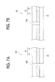
- FIGS. 7A and 7B are cross-sectional views showing the label related to the second exemplary embodiment.
- FIG. 7A is equivalent to a B-B cross-sectional view of FIG. 6
- FIG. 7B is equivalent to a C-C cross-sectional view of FIG. 6 .
- a label 102 related to the second exemplary embodiment has a form including release paper 20 that covers the adhesion layer 14 of the label body 10 in the label 101 related to the first exemplary embodiment.
- the label 102 related to the second exemplary embodiment includes, for example, the belt-like label body 10 having the base 12 and the adhesion layer 14 provided on one surface of the base 12 , the magnetic wire 16 arranged in the label body 10 along the longitudinal direction of the label body 10 , and the release paper 20 that covers the adhesion layer 14 of the label body 10 .
- the label body 10 has, for example, plural first cut portions 18 A provided by cutting the label body 10 , the magnetic wire 16 , and the release paper 20 along the width direction of the label body 10 except for both ends of the label body 10 in the width direction, and provided at intervals in the longitudinal direction of the label body 10 , and second cut portions 18 B provided by cutting both ends of the label body 10 in the width direction continuously with the first cut portion 18 A along the width direction of the label body 10 .
- the first cut portion 18 A is equivalent to the cut portion 18 of the label 101 related to the first exemplary embodiment (here, in the present exemplary embodiment, the first cut portion 18 A also cuts the release paper 20 along with the label body 10 and the magnetic wire 16 ), and the specific forms thereof are the same.
- the second cut portion 18 B formed continuously with the first cut portions 18 A is provided in so-called half-cut in which the label body 10 is cut and the release paper 20 is not cut.
- the second cut portions 18 B may be continuously provided or may be intermittently provided, along the width direction of the label body 10 .
- the present exemplary embodiment shows a form in which the second cut portions 18 B are continuously provided.
- the release paper 20 may also be cut along with the label body 10 .
- the release paper 20 includes release paper obtained by subjecting a base to impregnation processing or surface processing using a release agent.
- the base includes, for example, high-quality paper, poly-laminate paper, kraft paper, recycled paper, coated paper, and the like.
- the release agent includes release agents, such as a silicone resin release agent, waxes, a higher fatty acid release agent, a higher alcohol release agent, and a higher fatty acid amide release agent, and the silicone resin release agent is better.
- the impregnation processing or surface processing of the release agent to the base may be performed by well-known methods.
- the basis weight of the release paper 20 includes, for example, a range of 50 g/m 2 or more and 180 g/m 2 or less.
- the label 102 related to the present exemplary embodiment is the same as the label 101 related to a first exemplary embodiment except the above configuration, the description thereof is omitted.
- the first cut portion 18 A provided by cutting the label body 10 , the magnetic wire 16 , and the release paper 20 is provided in advance similarly to the first exemplary embodiment. Therefore, poor cutting of the magnetic wire 16 by the label cutter is suppressed.
- the second cut portions 18 B are provided in advance continuously with the first cut portion 18 A. Therefore, even when the label has the release paper 20 , cutting of the label body 10 by the label cutter becomes easy.
- the cut portion 18 A may have a form that provides the cut portion 18 except for a portion of the label body 10 in the width direction.
- the cut portion 18 A may have a form that is provided according to the arrangement position of the magnetic wire 16 in the label body 10 .
Abstract
Description
Claims (12)
Applications Claiming Priority (2)
| Application Number | Priority Date | Filing Date | Title |
|---|---|---|---|
| JP2011111772A JP5768493B2 (en) | 2011-05-18 | 2011-05-18 | label |
| JP2011-111772 | 2011-05-18 |
Publications (2)
| Publication Number | Publication Date |
|---|---|
| US20120295055A1 US20120295055A1 (en) | 2012-11-22 |
| US8852702B2 true US8852702B2 (en) | 2014-10-07 |
Family
ID=47155135
Family Applications (1)
| Application Number | Title | Priority Date | Filing Date |
|---|---|---|---|
| US13/287,433 Expired - Fee Related US8852702B2 (en) | 2011-05-18 | 2011-11-02 | Label |
Country Status (4)
| Country | Link |
|---|---|
| US (1) | US8852702B2 (en) |
| JP (1) | JP5768493B2 (en) |
| KR (1) | KR101491735B1 (en) |
| CN (1) | CN102789741A (en) |
Families Citing this family (4)
| Publication number | Priority date | Publication date | Assignee | Title |
|---|---|---|---|---|
| US20130192111A1 (en) * | 2012-01-31 | 2013-08-01 | The Kennedy Group Incorporated | Advertising media |
| SG11201506039PA (en) * | 2013-02-08 | 2015-09-29 | Toppan Forms Co Ltd | Label |
| CN103778850A (en) * | 2013-12-18 | 2014-05-07 | 中山市美高力印刷有限公司 | Self-adhesive label |
| US11250732B2 (en) * | 2019-02-01 | 2022-02-15 | Gang Chen | Screen sticker and method for making the same |
Citations (8)
| Publication number | Priority date | Publication date | Assignee | Title |
|---|---|---|---|---|
| US3885334A (en) * | 1972-08-17 | 1975-05-27 | Monarch Marking Systems Inc | Record assembly |
| US4568921A (en) * | 1984-07-13 | 1986-02-04 | Knogo Corporation | Theft detection apparatus and target and method of making same |
| JPH1069223A (en) | 1996-08-27 | 1998-03-10 | Casio Comput Co Ltd | Printing material |
| JP2005145023A (en) | 2003-11-20 | 2005-06-09 | Osaka Sealing Printing Co Ltd | Method and device for manufacturing continuous label material with wire rod |
| US7033657B2 (en) * | 2003-02-26 | 2006-04-25 | Crane Productions, Inc. | Magnetic wafer seal |
| US20080013212A1 (en) * | 2006-07-12 | 2008-01-17 | Fuji Xerox Co., Ltd. | Magnetic wire and recording medium |
| US20100117349A1 (en) * | 2008-11-11 | 2010-05-13 | Fuji Xerox Co., Ltd. | Label sheet |
| US7790259B2 (en) * | 2006-03-17 | 2010-09-07 | Hung-Chih Wu | Cut-free magnetic tape structure |
Family Cites Families (9)
| Publication number | Priority date | Publication date | Assignee | Title |
|---|---|---|---|---|
| US4660025A (en) * | 1984-11-26 | 1987-04-21 | Sensormatic Electronics Corporation | Article surveillance magnetic marker having an hysteresis loop with large Barkhausen discontinuities |
| JPH08305971A (en) * | 1995-04-28 | 1996-11-22 | Nhk Spring Co Ltd | Label for article monitoring and supply device for the same |
| JP2929094B2 (en) * | 1997-03-10 | 1999-08-03 | アイム株式会社 | How to make a magnetic label |
| JP2001341370A (en) * | 2000-06-02 | 2001-12-11 | Sato Corp | Printer |
| JP2003226314A (en) * | 2002-01-31 | 2003-08-12 | Honda Motor Co Ltd | Label tape and method for using it |
| JP2006184519A (en) * | 2004-12-27 | 2006-07-13 | Sato Corp | Label continuous body and its manufacturing method |
| CN2825282Y (en) * | 2005-07-04 | 2006-10-11 | 白文新 | Cladding type magnetic self-adhesive antitheft label |
| CN201408509Y (en) * | 2009-02-17 | 2010-02-17 | 杭州中瑞思创科技有限公司 | Novel permanent magnet label and commodity anti-theft device applying same |
| US8485723B2 (en) * | 2009-08-12 | 2013-07-16 | Tsi Technologies Llc | One-time sensor device |
-
2011
- 2011-05-18 JP JP2011111772A patent/JP5768493B2/en active Active
- 2011-11-02 US US13/287,433 patent/US8852702B2/en not_active Expired - Fee Related
-
2012
- 2012-01-03 KR KR20120000396A patent/KR101491735B1/en active IP Right Grant
- 2012-01-04 CN CN2012100012832A patent/CN102789741A/en active Pending
Patent Citations (8)
| Publication number | Priority date | Publication date | Assignee | Title |
|---|---|---|---|---|
| US3885334A (en) * | 1972-08-17 | 1975-05-27 | Monarch Marking Systems Inc | Record assembly |
| US4568921A (en) * | 1984-07-13 | 1986-02-04 | Knogo Corporation | Theft detection apparatus and target and method of making same |
| JPH1069223A (en) | 1996-08-27 | 1998-03-10 | Casio Comput Co Ltd | Printing material |
| US7033657B2 (en) * | 2003-02-26 | 2006-04-25 | Crane Productions, Inc. | Magnetic wafer seal |
| JP2005145023A (en) | 2003-11-20 | 2005-06-09 | Osaka Sealing Printing Co Ltd | Method and device for manufacturing continuous label material with wire rod |
| US7790259B2 (en) * | 2006-03-17 | 2010-09-07 | Hung-Chih Wu | Cut-free magnetic tape structure |
| US20080013212A1 (en) * | 2006-07-12 | 2008-01-17 | Fuji Xerox Co., Ltd. | Magnetic wire and recording medium |
| US20100117349A1 (en) * | 2008-11-11 | 2010-05-13 | Fuji Xerox Co., Ltd. | Label sheet |
Also Published As
| Publication number | Publication date |
|---|---|
| KR101491735B1 (en) | 2015-02-09 |
| JP2012242559A (en) | 2012-12-10 |
| CN102789741A (en) | 2012-11-21 |
| JP5768493B2 (en) | 2015-08-26 |
| KR20120129754A (en) | 2012-11-28 |
| US20120295055A1 (en) | 2012-11-22 |
Similar Documents
| Publication | Publication Date | Title |
|---|---|---|
| US8852702B2 (en) | Label | |
| CN102147453B (en) | Magnetic sensor device | |
| TWI595404B (en) | Electromagnetic induction sensor, overlay member for electromagnetic induction sensor, and manufacturing method of electromagnetic induction sensor | |
| TW451232B (en) | Inductive element | |
| KR950704820A (en) | Magneto-resistance device, and magnetic head employing such a device | |
| JP5765907B2 (en) | Magnetic members and electronic parts | |
| CN102792401A (en) | Magnetic element for wireless power transmission and power supply device | |
| CN102446615B (en) | Magnetic element | |
| JP7450607B2 (en) | Coil and its manufacturing method | |
| KR930003020A (en) | Thin film magnetic head | |
| JP2011119661A5 (en) | ||
| KR101084227B1 (en) | Label sheet | |
| JP6245043B2 (en) | Noise suppression cable | |
| KR101581067B1 (en) | Magnetic sensor unit | |
| KR101838115B1 (en) | Magnetic component | |
| NL8600390A (en) | MAGNETIC HEAD WITH MAGNETIC RESISTANCE ELEMENT. | |
| JP6487089B2 (en) | Manufacturing method of electromagnetic induction sensor | |
| US8045292B2 (en) | Perpendicular magnetic recording head with the return yoke layer having gradually increasing the width | |
| JP5655564B2 (en) | Label paper and manufacturing method thereof | |
| JP2010040914A (en) | Magnetization method of multi-pole magnet, and multi-pole magnet and magnetic encoder using the same | |
| JP4844603B2 (en) | Label paper | |
| JP2002312735A (en) | Tag and booklet body | |
| JPH09134817A (en) | Magnetic marker | |
| KR20120120054A (en) | Current sensor with a magnetic core | |
| JP2008140446A (en) | Perpendicular magnetic recording head device |
Legal Events
| Date | Code | Title | Description |
|---|---|---|---|
| AS | Assignment |
Owner name: FUJI XEROX CO., LTD., JAPAN Free format text: ASSIGNMENT OF ASSIGNORS INTEREST;ASSIGNORS:KURIHARA, EIZO;SAKAMAKI, KATSUMI;FUSE, MARIO;AND OTHERS;REEL/FRAME:027174/0670 Effective date: 20111025 |
|
| STCF | Information on status: patent grant |
Free format text: PATENTED CASE |
|
| FEPP | Fee payment procedure |
Free format text: PAYOR NUMBER ASSIGNED (ORIGINAL EVENT CODE: ASPN); ENTITY STATUS OF PATENT OWNER: LARGE ENTITY |
|
| MAFP | Maintenance fee payment |
Free format text: PAYMENT OF MAINTENANCE FEE, 4TH YEAR, LARGE ENTITY (ORIGINAL EVENT CODE: M1551) Year of fee payment: 4 |
|
| AS | Assignment |
Owner name: FUJIFILM BUSINESS INNOVATION CORP., JAPAN Free format text: CHANGE OF NAME;ASSIGNOR:FUJI XEROX CO., LTD.;REEL/FRAME:058287/0056 Effective date: 20210401 |
|
| FEPP | Fee payment procedure |
Free format text: MAINTENANCE FEE REMINDER MAILED (ORIGINAL EVENT CODE: REM.); ENTITY STATUS OF PATENT OWNER: LARGE ENTITY |
|
| LAPS | Lapse for failure to pay maintenance fees |
Free format text: PATENT EXPIRED FOR FAILURE TO PAY MAINTENANCE FEES (ORIGINAL EVENT CODE: EXP.); ENTITY STATUS OF PATENT OWNER: LARGE ENTITY |
|
| STCH | Information on status: patent discontinuation |
Free format text: PATENT EXPIRED DUE TO NONPAYMENT OF MAINTENANCE FEES UNDER 37 CFR 1.362 |
|
| FP | Lapsed due to failure to pay maintenance fee |
Effective date: 20221007 |