US8860671B2 - Depressable touch sensor - Google Patents
Depressable touch sensor Download PDFInfo
- Publication number
- US8860671B2 US8860671B2 US12/768,452 US76845210A US8860671B2 US 8860671 B2 US8860671 B2 US 8860671B2 US 76845210 A US76845210 A US 76845210A US 8860671 B2 US8860671 B2 US 8860671B2
- Authority
- US
- United States
- Prior art keywords
- arm
- touch sensor
- base
- end portion
- end portions
- Prior art date
- Legal status (The legal status is an assumption and is not a legal conclusion. Google has not performed a legal analysis and makes no representation as to the accuracy of the status listed.)
- Active, expires
Links
Images


Classifications
-
- G—PHYSICS
- G06—COMPUTING; CALCULATING OR COUNTING
- G06F—ELECTRIC DIGITAL DATA PROCESSING
- G06F3/00—Input arrangements for transferring data to be processed into a form capable of being handled by the computer; Output arrangements for transferring data from processing unit to output unit, e.g. interface arrangements
- G06F3/01—Input arrangements or combined input and output arrangements for interaction between user and computer
- G06F3/03—Arrangements for converting the position or the displacement of a member into a coded form
- G06F3/033—Pointing devices displaced or positioned by the user, e.g. mice, trackballs, pens or joysticks; Accessories therefor
- G06F3/0354—Pointing devices displaced or positioned by the user, e.g. mice, trackballs, pens or joysticks; Accessories therefor with detection of 2D relative movements between the device, or an operating part thereof, and a plane or surface, e.g. 2D mice, trackballs, pens or pucks
- G06F3/03547—Touch pads, in which fingers can move on a surface
Definitions
- This invention generally relates to electronic devices, and more specifically relates to sensor devices and using sensor devices for producing user interface inputs.
- Proximity sensor devices are widely used in a variety of electronic systems.
- a proximity sensor device typically includes a sensing region, often demarked by a surface, which uses capacitive, resistive, inductive, optical, acoustic and/or other technology to determine the presence, location and/or motion of one or more fingers, styli, and/or other objects.
- the proximity sensor device, together with finger(s) and/or other object(s) may be used to provide an input to the electronic system.
- proximity sensor devices are used as input devices for larger computing systems, such as those found integral within notebook computers or peripheral to desktop computers.
- Proximity sensor devices are also used in smaller systems, including handheld systems such as personal digital assistants (PDAs), remote controls, digital cameras, video cameras, communication systems such as wireless telephones and text messaging systems.
- PDAs personal digital assistants
- proximity sensor devices are used in media systems, such as CD, DVD, MP3, video or other media recorders or players.
- a typical UI includes a screen for displaying graphical and/or textual elements.
- the proximity sensor device may function as a value adjustment device, cursor control device, selection device, scrolling device, graphics/character/handwriting input device, menu navigation device, gaming input device, button input device, keyboard and/or other input device.
- One common application for a proximity sensor device is as a touch screen. In a touch screen, the proximity sensor is combined with a display screen for displaying graphical and/or textual elements. Together, the proximity sensor and display screen function as the user interface.
- click touchpad or “click pad” technology has been developed which allows touchpads, touch screens, and other touch sensors to provide tactile feedback by being at least partially depressable or “clickable.”
- the “click” may be purely for tactile feedback or may be used to generate a signal that is used by the electronic system in which the click pad is installed.
- the embodiments of the present invention provide a device and method that facilitates improved sensor device usability. Specifically, the device and method provide improved usability by facilitating the substantially uniform translation or depression of a sensor support in a “click touch pad” or “click pad” input device in a reliable and inexpensive manner.
- an input device assembly includes a base, touch sensor, and a scissor mechanism positioned between the base and the touch sensor.
- the scissor mechanism includes a first arm and a second arm.
- the first arm has first and second end portions and first and second side portions interconnecting the first and second end portions.
- the first end portion of the first arm is rotatably mounted to one of the base and the touch sensor.
- the second end portion of the first arm is slidable relative to the other of the base and the touch sensor.
- the first and second end portions of the first arm are separated by a first distance.
- the second arm is rotatably coupled to and positioned between the first and second side portions of the first arm.
- the second arm has first and second end portions.
- the first end portion of the second arm is rotatably mounted to one of the base and the touch sensor.
- the second end portion of the first arm is slidable relative to the other of the base and the touch sensor.
- an input device assembly in another embodiment, includes a base, a touch sensor, a switch positioned between the base and the touch sensor, and a scissor mechanism positioned between the base and the touch sensor.
- the scissor mechanism includes a first arm and a second arm.
- the first arm has first and second end portions and first and second side portions interconnecting the first and second end portions.
- the first end portion of the first arm is rotatably mounted to one of the base and the touch sensor.
- the second end portion of the first arm is slidable relative to the other of the base and the touch sensor.
- the first and second end portions of the first arm are separated by a first distance.
- the second arm includes first and second end portions and first and second side portions interconnecting the first and second end portions.
- the first side portion of the second arm is rotatably coupled to the first side portion of the first arm.
- the second side portion of the second arm is rotatably coupled to the second side portion of the first arm.
- the first and second side portions of the second arm are positioned between the first and second side portions of the first arm.
- the first end portion of the second arm is rotatably mounted to one of the base and the touch sensor.
- the second end portion of the first arm is slidable relative to the other of the base and the touch sensor.
- the first and second end portions of the second arm are separated by a second distance. The second distance is less than the first distance.
- Deflection of the touch sensor causes the first end portion of the first arm to rotate relative to the one of the base and the touch sensor, the second end portion of the first arm to slide relative to the other of the base and the touch sensor, the first end portion of the second arm to rotate relative to the one of the base and the touch sensor, the second end portion of the second arm to slide relative to the other of the base and the touch sensor, and actuation of the switch.
- the first and second arms of the scissor mechanism are sized and shaped such that sufficient deflection of the touch sensor causes the first and second end potions of the second arm to be positioned directly between the first and second end portions of the first arm.
- a method of providing an input device assembly is provided.
- a base and a touch sensor are provided.
- the base and the touch sensor are interconnected with a scissor mechanism positioned between the base and the touch sensor.
- the scissor mechanism includes a first arm and a second arm.
- the first arm has first and second end portions and first and second side portions interconnecting the first and second end portions.
- the first end portion of the first arm is rotatably mounted to one of the base and the touch sensor.
- the second end portion of the first arm is slidable relative to the other of the base and the touch sensor.
- the first and second end portions of the first arm are separated by a first distance.
- the second arm is rotatably coupled to and positioned between the first and second side portions of the first arm.
- the second arm has first and second end portions.
- the first end portion of the second arm is rotatably mounted to one of the base and the touch sensor.
- the second end portion of the first arm is slidable relative to the other of the base and the touch sensor.
- FIG. 1 is a block diagram of an exemplary system that includes an input device in accordance with an embodiment of the invention
- FIG. 2 is an exploded isometric view of an exemplary input device in accordance with an embodiment of the invention
- FIG. 3 is an isometric view of the input device of FIG. 2 ;
- FIG. 4 is an isometric view of a bottom of a sensor support and a scissor mechanism within the input device of FIG. 2 ;
- FIG. 5 is a plan view of the sensor support and the scissor mechanism of FIG. 4 ;
- FIG. 6 is a plan view of a base of the input device of FIG. 2 and the scissor mechanism;
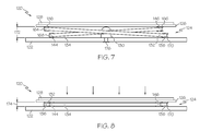
- FIGS. 7 and 8 are side views of the input device taken along line 7 - 7 in FIG. 3 ;
- FIGS. 9 , 10 , 11 , and 12 are cross-sectional view of the input device of FIGS. 7 and 8 .
- the input devices and methods relate user input to the input devices and resulting actions on displays.
- user input in sensing regions of the input devices and methods of processing the user input allow users to interact with electronic systems, thus providing more enjoyable user experiences and improved performance.
- FIG. 1 is a block diagram of an exemplary electronic system 100 that is coupled to an input device 116 , shown as a proximity sensor device (also often referred to as a touch pad, a touch sensor, or a “click pad”).
- a proximity sensor device also often referred to as a touch pad, a touch sensor, or a “click pad”.
- an input device associated with an electronic system can be implemented as part of the electronic system, or coupled to the electronic system using any suitable technique.
- the electronic system may comprise another input device (such as a physical keypad or another touch sensor device).
- the electronic system includes personal computers such as desktop computers, laptop computers, portable computers, workstations, personal digital assistants, video game machines. Examples of the electronic system also include communication devices such as wireless phones, pagers, and other messaging devices. Other examples of the electronic system include media devices that record and/or play various forms of media, including televisions, cable boxes, music players, digital photo frames, video players, digital cameras, video camera. In some cases, the electronic system is peripheral to a larger system.
- the electronic system could be a data input device such as a remote control, or a data output device such as a display system, that communicates with a computing system using a suitable wired or wireless technique.
- the elements communicatively coupled to the electronic system, and the parts of the electronic system, may communicate via any combination of buses, networks, and other wired or wireless interconnections.
- an input device may be in operable communication with its associated electronic system through any type of interface or connection.
- available interfaces and connections include I 2 C, SPI, PS/2, Universal Serial Bus (USB), Bluetooth, RF, IRDA, and any other type of wired or wireless connection.
- the various elements (e.g. processors, memory, etc.) of the electronic system may be implemented as part of the input device associated with it, as part of a larger system, or as a combination thereof. Additionally, the electronic system could be a host or a slave to the input device. Accordingly, the various embodiments of the electronic system may include any type of processor, memory, or display, as needed.
- the input device 116 includes a sensing region 118 .
- the input device 116 is sensitive to input by one or more input objects (e.g. fingers, styli, etc.), such as the position of an input object 114 within the sensing region 118 .
- “Sensing region” as used herein is intended to broadly encompass any space above, around, in and/or near the input device in which sensor(s) of the input device is able to detect user input.
- the sensing region of an input device extends from a surface of the sensor of the input device in one or more directions into space until signal-to-noise ratios prevent sufficiently accurate object detection.
- this sensing region extends in a particular direction may be on the order of less than a millimeter, millimeters, centimeters, or more, and may vary significantly with the type of sensing technology used and the accuracy desired. Thus, embodiments may require contact with the surface, either with or without applied pressure, while others do not. Accordingly, the sizes, shapes, and locations of particular sensing regions may vary widely from embodiment to embodiment.
- Sensing regions with rectangular two-dimensional projected shape are common, and many other shapes are possible. For example, depending on the design of the sensor array and surrounding circuitry, shielding from any input objects, and the like, sensing regions may be made to have two-dimensional projections of other shapes. Similar approaches may be used to define the three-dimensional shape of the sensing region. For example, any combination of sensor design, shielding, signal manipulation, and the like may effectively define a sensing region 118 that extends some distance into or out of the page in FIG. 1 .
- the input device 116 suitably detects one or more input objects (e.g. the input object 114 ) within the sensing region 118 .
- the input device 116 thus includes a sensor (not shown) that utilizes any combination sensor components and sensing technologies to implement one or more sensing regions (e.g. sensing region 118 ) and detect user input such as presences of object(s).
- Input devices may include any number of structures, such as one or more sensor electrodes, one or more other electrodes, or other structures adapted to detect object presence.
- input devices may use capacitive, resistive, inductive, surface acoustic wave, and/or optical techniques. Many of these techniques are advantageous to ones requiring moving mechanical structures (e.g. mechanical switches) as they may have a substantially longer usable life.
- sensor(s) of the input device 116 may use arrays or other patterns of capacitive sensor electrodes to support any number of sensing regions 118 .
- the sensor may use capacitive sensing technology in combination with resistive sensing technology to support the same sensing region or different sensing regions. Examples of the types of technologies that may be used to implement the various embodiments of the invention may be found in U.S. Pat. Nos. 5,543,591, 5,648,642, 5,815,091, 5,841,078, and 6,249,234.
- a flexible and conductive top layer is separated by one or more spacer elements from a conductive bottom layer.
- a voltage gradient is created across the layers. Pressing the flexible top layer in such implementations generally deflects it sufficiently to create electrical contact between the top and bottom layers.
- the senor picks up loop currents induced by a resonating coil or pair of coils, and use some combination of the magnitude, phase and/or frequency to determine distance, orientation or position.
- a voltage is applied to create an electric field across a sensing surface.
- These capacitive input devices detect the position of an object by detecting changes in capacitance caused by the changes in the electric field due to the object.
- the sensor may detect changes in voltage, current, or the like.
- some capacitive implementations utilize resistive sheets, which may be uniformly resistive.
- the resistive sheets are electrically (usually ohmically) coupled to electrodes that receive from the resistive sheet.
- these electrodes may be located at corners of the resistive sheet, provide current to the resistive sheet, and detect current drawn away by input devices via capacitive coupling to the resistive sheet.
- these electrodes are located at other areas of the resistive sheet, and drive or receive other forms of electrical signals.
- the sensor electrodes are considered to be the resistive sheets, the electrodes coupled to the resistive sheets, or the combinations of electrodes and resistive sheets.
- some capacitive implementations utilize transcapacitive sensing methods based on the capacitive coupling between sensor electrodes.
- Transcapacitive sensing methods are sometimes also referred to as “mutual capacitance sensing methods.”
- a transcapacitive sensing method operates by detecting the electric field coupling one or more transmitting electrodes with one or more receiving electrodes. Proximate objects may cause changes in the electric field, and produce detectable changes in the transcapacitive coupling. Sensor electrodes may transmit as well as receive, either simultaneously or in a time multiplexed manner.
- Sensor electrodes that transmit are sometimes referred to as the “transmitting sensor electrodes,” “driving sensor electrodes,” “transmitters,” or “drivers”—at least for the duration when they are transmitting.
- Other names may also be used, including contractions or combinations of the earlier names (e.g. “driving electrodes” and “driver electrodes.”
- Sensor electrodes that receive are sometimes referred to as “receiving sensor electrodes,” “receiver electrodes,” or “receivers”—at least for the duration when they are receiving.
- other names may also be used, including contractions or combinations of the earlier names.
- a transmitting sensor electrode is modulated relative to a system ground to facilitate transmission.
- a receiving sensor electrode is not modulated relative to system ground to facilitate receipt.
- the processing system (or “processor”) 119 is coupled to the input device 116 and the electronic system 100 .
- Processing systems such as the processing system 119 may perform a variety of processes on the signals received from the sensor(s) of input devices such as the input device 116 .
- processing systems may select or couple individual sensor electrodes, detect presence/proximity, calculate position or motion information, or interpret object motion as gestures.
- processing systems may also determine when certain types or combinations of object motions occur in sensing regions.
- the processing system 119 may provide electrical or electronic indicia based on positional information of input objects (e.g. input object 114 ) to the electronic system 100 .
- input devices use associated processing systems to provide electronic indicia of positional information to electronic systems, and the electronic systems process the indicia to act on inputs from users.
- One example system responses is moving a cursor or other object on a display, and the indicia may be processed for any other purpose.
- a processing system may report positional information to the electronic system constantly, when a threshold is reached, in response criterion such as an identified stroke of object motion, or based on any number and variety of criteria.
- processing systems may directly process the indicia to accept inputs from the user, and cause changes on displays or some other actions without interacting with any external processors.
- processing system is defined to include one or more processing elements that are adapted to perform the recited operations.
- a processing system e.g. the processing system 119
- all processing elements that comprise a processing system are located together, in or near an associated input device.
- the elements of a processing system may be physically separated, with some elements close to an associated input device, and some elements elsewhere (such as near other circuitry for the electronic system). In this latter embodiment, minimal processing may be performed by the processing system elements near the input device, and the majority of the processing may be performed by the elements elsewhere, or vice versa.
- a processing system may be physically separate from the part of the electronic system (e.g. the electronic system 100 ) that it communicates with, or the processing system may be implemented integrally with that part of the electronic system.
- a processing system may reside at least partially on one or more integrated circuits designed to perform other functions for the electronic system aside from implementing the input device.
- the input device is implemented with other input functionality in addition to any sensing regions.
- the input device 116 of FIG. 1 may be implemented with buttons or other input devices near the sensing region 118 .
- the buttons may be used to facilitate selection of items using the proximity sensor device, to provide redundant functionality to the sensing region, or to provide some other functionality or non-functional aesthetic effect. Buttons form just one example of how additional input functionality may be added to the input device 116 .
- input devices such as the input device 116 may include alternate or additional input devices, such as physical or virtual switches, or additional sensing regions.
- the input device may be implemented with only sensing region input functionality.
- any positional information determined a processing system may be any suitable indicia of object presence.
- processing systems may be implemented to determine “zero-dimensional” 1-bit positional information (e.g. near/far or contact/no contact) or “one-dimensional” positional information as a scalar (e.g. position or motion along a sensing region).
- processing systems may also be implemented to determine multi-dimensional positional information as a combination of values (e.g. two-dimensional horizontal/vertical axes, three-dimensional horizontal/vertical/depth axes, angular/radial axes, or any other combination of axes that span multiple dimensions), and the like.
- Processing systems may also be implemented to determine information about time or history.
- positional information is intended to broadly encompass absolute and relative position-type information, and also other types of spatial-domain information such as velocity, acceleration, and the like, including measurement of motion in one or more directions.
- Various forms of positional information may also include time history components, as in the case of gesture recognition and the like.
- positional information from processing systems may be used to facilitate a full range of interface inputs, including use of the proximity sensor device as a pointing device for cursor control, scrolling, and other functions.
- an input device such as the input device 116 may be adapted as part of a touch screen interface.
- a display screen is overlapped by at least a portion of a sensing region of the input device, such as the sensing region 118 .
- the input device and the display screen provide a touch screen for interfacing with an associated electronic system.
- the display screen may be any type of electronic display capable of displaying a visual interface to a user, and may include any type of LED (including organic LED (OLED)), CRT, LCD, plasma, EL or other display technology.
- OLED organic LED
- the input devices may be used to activate functions on the electronic systems.
- touch screen implementations allow users to select functions by placing one or more objects in the sensing region proximate an icon or other user interface element indicative of the functions.
- the input devices may be used to facilitate other user interface interactions, such as scrolling, panning, menu navigation, cursor control, parameter adjustments, and the like.
- the input devices and display screens of touch screen implementations may share physical elements extensively. For example, some display and sensing technologies may utilize some of the same electrical components for displaying and sensing.
- the mechanisms of the present invention are capable of being distributed as a program product in a variety of forms.
- the mechanisms of the present invention may be implemented and distributed as a sensor program on computer-readable media.
- the embodiments of the present invention apply equally regardless of the particular type of computer-readable medium used to carry out the distribution. Examples of computer-readable media include various discs, memory sticks, memory cards, memory modules, and the like.
- Computer-readable media may be based on flash, optical, magnetic, holographic, or any other storage technology.
- the input device 116 utilizes “click pad” technology.
- the touch sensor(s) used may be based on any type of touch-related technology, including resistive, capacitive, inductive, surface acoustic wave (SAW), optical, and the like.
- SAW surface acoustic wave
- the depressing of the touch sensor, or the “click,” may be purely for tactile feedback.
- the click provides input information used to provide other responses in the electronic system 100 .
- the click may involve actuation of a binary or multi-stage switch, change a reading of a digital or analog force sensor, change a reading of a displacement sensor, or the like.
- the response to the switch actuation or force change can be non-varying or variable.
- Non-varying responses include selection, emulation of specific mouse button clicks, confirmation of a command, and the like.
- Variable responses may be dependent on context such as which window is active in an associated GUI, which software application is active, which function is active, options then available to the user, the amount of force or displacement sensed, displays shown, position(s) of one or more input objects in the sensing region of the touch sensor, a combination thereof, or the like.
- the click pad may be integral or peripheral to computing devices, including terminals, desktops, laptops, PDAs, cell phones, remote controls, etc.
- the click pad may communicate via any wired or wireless protocols.
- switches examples include snap dome buttons (which may be enabled with a Belleville spring or some other mechanism) and various types of microswitches.
- the switches may be binary or have multiple positions or switch levels. Any variety of switch technology, including electrical contact, resistive, or capacitive, may be used.
- Examples of other sensors include force sensors (e.g. strain gauges) or displacement sensors (e.g. linear position sensors). These sensors may supply finer resolution information. Finer resolution information may be used to provide multiple different levels of actuation (even continuous changes akin to analog readings) for controlling various parameters (e.g. volume, speed, etc).
- force sensors e.g. strain gauges
- displacement sensors e.g. linear position sensors
- These sensors may supply finer resolution information. Finer resolution information may be used to provide multiple different levels of actuation (even continuous changes akin to analog readings) for controlling various parameters (e.g. volume, speed, etc).
- the force sensed may not be the applied force (since the force transmitted to sensor may be a fraction or an amplification of the applied force, depending on the click pad design and potentially the location(s) of the input(s)). Since the touch sensor may be used to supply input location information, the actual force applied may be determined using the force reading as well as the location(s) of the input.
- sensors such as switches may be placed behind a touch sensor that is constrained in some way to move substantially repeatably in response to force applied to the touch sensor.
- the substrate may be constrained to translate, rotate, or translate and rotate in such a way that it can activate the switch (or other sensor) used.
- Some embodiments may implement keypads using touch sensors.
- a keypad may be demarked by a dynamic display (e.g. an LCD) or statically imprinted on a surface of the touch sensor device.
- the associated touch sensor may relay the location(s) of the user input to a host processor that determines which key(s) should be activated in response. Criteria such as a minimum amount of force or a minimum duration of user contact may be applied to qualify the actuation.
- the system may respond to the activated key by passing the key information to another system or another part of the system, by entering the associated input (e.g. a letter, number, or function), by displaying visual feedback, or by taking any other appropriate action (e.g. by dialing a phone number if the keypad is that of a phone).
- Motion of the touch sensor may be implemented in various ways.
- the system may be designed to provide substantially uniform translation in response to actuation force applied to different locations across a surface of the touch sensor.
- a linear slide may be used to constrain the motion of the substrate such that the substrate does not tilt, twist, or slide (e.g. toward actuation of a switch or interaction with a force or displacement sensor).
- FIG. 2 illustrates, in an exploded manner, an exemplary input device assembly 120 which utilizes “click touchpad” or “click pad” technology and may be implemented in the input device 116 .
- the input device assembly 120 includes a base (or lower bracket) 122 , a scissor or guide mechanism (or assembly) 124 , a sensor support 126 , and a touch sensor (e.g., a capacitive touch sensor) 128 .
- all of the components of the input device assembly 120 are substantially rectangular and arranged such that the scissor mechanism 124 is positioned between (and interconnects) the base 122 and the sensor support 126 and the touch sensor 128 is positioned over the sensor support 126 .
- the base 122 and the sensor support 126 may be made of a metal, a composite, or plastic.
- the input device assembly 120 further includes a switch (e.g., a snap dome button) 130 connected to a central portion of the base 122 on a side adjacent to the scissor mechanism 124 .
- the input device assembly 120 may also include an upper bracket arranged around a periphery of the touch sensor 128 , a cover sheet (e.g., made of Mylar) over the touch sensor 128 , and various adhesive layers or films.
- FIGS. 3 , 4 , and 5 illustrates the input device assembly 120 partially assembled.
- the touch sensor 128 is centered on and mounted to the sensor support 126 .
- the scissor mechanism 124 is positioned between and connected to the base 122 and the sensor support 126 (and/or the touch sensor 128 ).
- FIGS. 4 and 5 illustrate a lower surface (or bottom) of the sensor support 126 and the scissor mechanism 124 .
- the scissor mechanism 124 includes a first arm 132 and a second arm 134 .
- the first and second arms 132 and 134 are substantially rectangular in shape and constructed from wire-like pieces of metal (e.g., steel or aluminum).
- the first arm 132 includes end portions 136 and 138 and side portions 140 and 142 , which interconnect the end portions 136 and 138 .
- the second arm includes end portions 144 and 146 and side portions 148 and 150 . It should be understood that the descriptors used for the end portions and side portions of the arms of the scissor mechanism 124 may be interchanged.
- the first and second arms 132 and 134 may be made of other materials, such as other metals, composite materials, and plastics, and may be in different shapes, such as squares and other polygons.
- the side portions 148 and 150 of the second arm 134 are positioned between the side portions 140 and 142 of the first arm 132 , and the first and second arms 132 and 134 are sized such that the first arm 132 is large enough to completely surround the second arm 134 . More specifically, a distance 152 between the inner edges of the end portions 136 and 138 of the firm arm 132 is greater than a distance 154 between (the outer edges of) the end portions 144 and 146 of the second arm 134 . Similarly, a distance 156 between (the inner edges) of the side portions 140 and 142 of the first arm 132 is greater than a distance 158 between (the outer edges of) the side portions 148 and 150 of the second arm 134 .
- the distances 152 - 156 substantially correspond to the lengths and/or widths of the first and second arms 132 and 134 and that the lengths and/or widths of the first and second arms 132 and 134 extend substantially the entire length and/or width of the sensor support 126 .
- the scissor mechanism 124 does not increase the “footprint” (i.e., lateral surface area covered) of the input device assembly 120 . That is, the scissor mechanism 124 is sized and arranged relative to the base 122 , the sensor support 126 , and the touch sensor 128 such that the scissor mechanism 124 is contained within the outermost perimeter of the other components.
- the footprint of the input device assembly 120 is defined solely by the base 122 , as the base 122 extends laterally farther than the other components in all directions.
- first and second arms 132 and 134 are rotatably attached (or coupled) at pivots, or at pivot points, (and/or by pivot pins) 160 and 162 . More specifically, pivot pin 160 interconnects side portion 140 of the first arm 132 with side portion 148 of the second arm 134 , and pivot pin 162 interconnects side portion 142 of the first arm 132 with side portion 150 of the second arm 134 . It should be noted that the pivot points (or pins) 160 and 162 are not located equidistantly from the end portions of the first and second arms 132 and 134 .
- the pivot points 160 and 162 are closer to end portions 138 and 146 than they are to end portions 136 and 144 .
- the pivots points 160 may be equidistant from the end portions of the first and second arms 132 and 134 (i.e., the pivot points may be positioned at the center of the side portions 140 , 142 , 148 , and 150 of the first and second arms 132 and 134 ).
- end portion 136 of the first arm 132 is connected to the sensor support 126 by pivot bracket 164 (described in greater detail below), and end portion 146 of the second arm 134 is connected to the sensor support 126 by slide bracket 166 (described in greater detail below).
- FIG. 6 illustrates the base 122 and the scissor mechanism 124 .
- the switch 130 is positioned between the opposing end and side portions of the first and second arms 132 and 134 . That is, the first and second arms 132 and 134 surround or circumscribe the switch 130 .
- End portion 144 of the second arm 134 is connected to the base 122 by pivot bracket 168
- end portion 138 of the first arm 132 is connected to the base 122 by slide bracket 170 .
- the brackets 164 , 166 , 168 and 170 are made of steel. However, other materials, such as other metals, composites, and plastics may be used.
- the brackets 164 , 166 , 168 , and 170 may be affixed to the base 122 and the sensor support 126 using, for example, rivets, screws, welding, laser welding, caulking (or a caulking joint), adhesive (e.g., glue), or any combination thereof.
- adjacent end portions 136 and 144 are connected to the sensor support 126 and the base 122 , respectively, by pivot brackets 164 and 168 . While end portions 138 and 146 (i.e., the end portions on the other side of the switch 130 ) are connected to the base 122 and the sensor support 126 , respectively, by slide brackets 166 and 170 .
- the switch 130 when the input device assembly 120 is assembled, the switch 130 , or a spring-like mechanism within the switch 130 (e.g., a Belleville spring), applies an “upwards” force to the sensor support 126 (i.e., away from the base 122 ). In some embodiments, the switch 130 may be the only source for this upwards force applied to the sensor support 126 .
- a spring-like mechanism within the switch 130 e.g., a Belleville spring
- the scissor mechanism 124 may include a spring-like mechanism (not shown) coupled to the first and second arms 132 and 134 , which causes the scissor mechanism 124 itself to apply a force to the sensor support 126 (i.e., solely or in combination withy the switch 130 ) in a manner similar to that of the switch 130 as described above.
- the connections between the scissor mechanism 124 , the base 122 , and the sensor support 126 causes the arms 132 and 134 of the scissor mechanism 124 to be arranged in the “crossed” or “expanded” configuration shown in FIG. 7 which lifts the sensor support 126 (and the touch sensor 128 ) away from the base 122 .
- the sensor support may be suspended a first height 172 above the base 122 .
- the first height may be, for example, between 1.0 and 3.0 mm.
- the touch sensor 128 is used to receive user input in the manner described above.
- the user simply applies a force onto, or into, the touch sensor 128 , using the input object 114 (e.g., a finger or a stylus).
- the input object 114 e.g., a finger or a stylus.
- the force applied by the user causes the sensor support 126 to move towards the base while the switch 130 (and/or the scissor mechanism 124 ) applies a force that opposes the movement of the sensor support 126 .
- the switch 130 is actuated to the point where it, in accordance with normal operation, generates a suitable signal which is sent to the processor 119 ( FIG. 1 ). That is, the switch is “activated.”
- the particular magnitude of the actuation distance is dependent on how much “travel” the switch 130 has (i.e., how much actuation is needed to activate the switch), the position of the switch 130 relative to the base 122 .
- the switch 130 is connected to the base 122 via an adjustment mechanism 176 (e.g., a screw) which allows the switch 130 to be raised and lowered relative to the base 122 .
- the actuation distance may be adjusted by utilizing a particular kind of switch and tuning the position of the switch with the adjustment mechanism 176 .
- the activation of the switch provides a particular tactile feel to the user by, for example, providing a different amount of resistance to further actuating the switch 130 .
- the activation of the switch 130 may also be accompanied by an audible sound, such as a “click.”
- the second arm 134 rotates relative to the first arm 132 about the pivot point 160 and 162 ( FIG. 4 ).
- the rotation causes the arms 132 and 134 become less “crossed” and more “aligned” and “collapsed” as shown in FIGS. 8 , 10 , and 12 .
- the end portions 136 and 144 of the arms 132 and 134 that are connected to the sensor support 126 and the base 122 by the pivot brackets 164 and 168 rotate (or pivot). Specifically, end portion 136 does not slide across the sensor support 126 , and end portion 144 does not slide relative to the base 122 .
- end portions 138 and 146 of the arms 132 and 134 that are connected to the sensor support 126 and the base 122 by the slide brackets 166 and 170 slide within the brackets 166 and 170 .
- end portion 138 slides across the base 122 (within the bracket 170 )
- end portion 146 slides across the sensor support 126 (within the bracket 166 ).
- end portions 138 and 146 may also experience some rotation as the sensor support 126 moves towards the base 122 .
- the scissor mechanism 124 and the switch 130 may be configured such that the sensor support 126 may be depressed so far as to completely collapse the scissor mechanism 124 . That is, in one embodiment, the scissor mechanism 124 is configured to be able to “lie flat,” as the end portions 144 and 146 of the second arm 134 may be positioned directly between the end portions 136 and 138 of the first arm 132 . Such a feature may be facilitated by the second arm 134 being smaller than the first arm 132 and the pivot points 160 and 162 not being equidistant from the ends of the arms.
- the sensor support 126 When the scissor mechanism 124 is completely collapsed, the sensor support 126 may be suspended a second height 174 ( FIG. 8 ) above the base 122 .
- the second height 174 may be between 0.5 and 2.0 mm and correspond to the thicknesses of the first and second arms 132 and 134 (of the scissor mechanism 124 (i.e., respective first and second thickness which may be substantially equal) and the height of the switch 130 when actuated (e.g., when the dome portion is collapsed).
- the sensor support 126 moves towards the base in a substantially “uniform” manner. That is, having the end portions of each of the arms 132 and 134 fixed relative to the sensor support 126 and the base 122 , and yet still able to rotate, while allowing the opposing end portions to slide, minimizes any tilting and/or sliding experienced by the sensor support 126 . Additionally, because of the arms 132 and 134 span across nearly the entire length and/or width of the sensor support 126 , the amount of twisting (i.e., rotation about an axis perpendicular to the touch sensor 128 ) experienced by the sensor support 126 is reduced.
- the switch 130 When the user releases or lifts the input object from the touch sensor 128 , the switch 130 reflects the sensor support 126 and causes it to return to the position shown in FIG. 7 . This movement may also be substantially uniform, as little or no twisting, tilting, or sliding may be experienced, for the same reasons as those described above with respect to the sensor support 126 moving towards the base 122 .
- a sensor device comprises an array of capacitive sensing electrodes and a processing system coupled to the electrodes.
- the capacitive sensing electrodes are configured to generate sensing signals that are indicative of objects in a sensing region.
- the processing system is configured to receive sensing signals from the capacitive sensing electrodes and generate a plurality of sensing values, each of the plurality of sensing values corresponding to a sensing electrode in the first array of capacitive sensing electrodes.
- the processing system is further configured to produce a plurality of positional values corresponding to a plurality of groups of electrodes in the first array of capacitive sensing electrodes; analyze the plurality of positional values to determine if one or more clusters exist in the plurality of positional values; and determine a number of objects in the sensing region from the determined one or more clusters in the plurality of positional values.
- the sensor device facilitates the determination of the number of objects in the sensing region, and can thus be used to facilitate different user interface actions in response to different numbers of objects.
Abstract
Description
Claims (19)
Priority Applications (1)
| Application Number | Priority Date | Filing Date | Title |
|---|---|---|---|
| US12/768,452 US8860671B2 (en) | 2009-05-28 | 2010-04-27 | Depressable touch sensor |
Applications Claiming Priority (4)
| Application Number | Priority Date | Filing Date | Title |
|---|---|---|---|
| US18188809P | 2009-05-28 | 2009-05-28 | |
| US25394409P | 2009-10-22 | 2009-10-22 | |
| US29506810P | 2010-01-14 | 2010-01-14 | |
| US12/768,452 US8860671B2 (en) | 2009-05-28 | 2010-04-27 | Depressable touch sensor |
Publications (2)
| Publication Number | Publication Date |
|---|---|
| US20100302153A1 US20100302153A1 (en) | 2010-12-02 |
| US8860671B2 true US8860671B2 (en) | 2014-10-14 |
Family
ID=43218949
Family Applications (2)
| Application Number | Title | Priority Date | Filing Date |
|---|---|---|---|
| US12/729,969 Abandoned US20100300772A1 (en) | 2009-05-28 | 2010-03-23 | Depressable touch sensor |
| US12/768,452 Active 2032-10-04 US8860671B2 (en) | 2009-05-28 | 2010-04-27 | Depressable touch sensor |
Family Applications Before (1)
| Application Number | Title | Priority Date | Filing Date |
|---|---|---|---|
| US12/729,969 Abandoned US20100300772A1 (en) | 2009-05-28 | 2010-03-23 | Depressable touch sensor |
Country Status (2)
| Country | Link |
|---|---|
| US (2) | US20100300772A1 (en) |
| WO (1) | WO2010138288A2 (en) |
Cited By (4)
| Publication number | Priority date | Publication date | Assignee | Title |
|---|---|---|---|---|
| US20150009156A1 (en) * | 2013-07-02 | 2015-01-08 | Elan Microelectronics Corporation | Input device and lifting structure for the input device |
| US20150138112A1 (en) * | 2013-11-20 | 2015-05-21 | Nextinput, Inc. | Force sensor module for applying a preload force to a force sensor |
| US11429157B2 (en) * | 2020-02-21 | 2022-08-30 | Apple Inc. | Parallel motion trackpad |
| US11953952B2 (en) | 2022-07-22 | 2024-04-09 | Apple Inc. | Parallel motion trackpad |
Families Citing this family (28)
| Publication number | Priority date | Publication date | Assignee | Title |
|---|---|---|---|---|
| US9329719B2 (en) | 2007-03-15 | 2016-05-03 | Apple Inc. | Hybrid force sensitive touch devices |
| US8432301B2 (en) * | 2010-08-10 | 2013-04-30 | Mckesson Financial Holdings | Gesture-enabled keyboard and associated apparatus and computer-readable storage medium |
| US8816964B2 (en) | 2010-11-26 | 2014-08-26 | Mckesson Financial Holdings | Sensor-augmented, gesture-enabled keyboard and associated apparatus and computer-readable storage medium |
| US9235303B2 (en) | 2010-12-20 | 2016-01-12 | Intel Corporation | Micro deflectors on touch sensor |
| US9389721B2 (en) * | 2011-02-09 | 2016-07-12 | Apple Inc. | Snap domes as sensor protection |
| TW201237699A (en) * | 2011-03-11 | 2012-09-16 | Hon Hai Prec Ind Co Ltd | Touch control device and an electronic apparatus using the same |
| US8816978B2 (en) | 2011-08-31 | 2014-08-26 | Lenovo (Singapore) Pte. Ltd. | Seesaw touchpad with horizontal direction hinge |
| CN202502927U (en) | 2012-03-08 | 2012-10-24 | 纬创资通股份有限公司 | Key module and electronic device provided with same |
| US9069394B2 (en) | 2012-03-20 | 2015-06-30 | Google Inc. | Fully clickable trackpad |
| US20130257792A1 (en) | 2012-04-02 | 2013-10-03 | Synaptics Incorporated | Systems and methods for determining user input using position information and force sensing |
| US9262021B2 (en) | 2012-04-11 | 2016-02-16 | Synaptics Incorporated | Two layer capacitive sensor |
| US8847905B2 (en) | 2012-08-13 | 2014-09-30 | Lenovo (Singapore) Pte. Ltd. | Multi-texture for five button click pad top surface |
| US9098250B2 (en) * | 2013-07-17 | 2015-08-04 | Lenovo (Singapore) Pte. Ltd. | Computer assembly incorporating coupling within pantograph |
| US9720553B2 (en) * | 2014-12-30 | 2017-08-01 | Synaptics Incorporated | Input device including fold over sensor substrate |
| CN107209619B (en) * | 2015-01-16 | 2021-10-08 | 家居控制新加坡私人有限责任公司 | Clickable control panel |
| US9652069B1 (en) | 2015-10-22 | 2017-05-16 | Synaptics Incorporated | Press hard and move gesture |
| US10545543B2 (en) * | 2016-09-29 | 2020-01-28 | Texas Instruments Incorporated | Assembly for mounting touch sensor within device case |
| KR101956432B1 (en) * | 2016-11-03 | 2019-03-08 | 현대자동차주식회사 | Touch input device |
| WO2018129175A1 (en) * | 2017-01-04 | 2018-07-12 | Activbody, Inc. | Force measurement device |
| TWI664890B (en) * | 2018-04-13 | 2019-07-01 | 精元電腦股份有限公司 | Touch device |
| WO2020172824A1 (en) * | 2019-02-27 | 2020-09-03 | 华为技术有限公司 | Input apparatus, and electronic device comprising input apparatus |
| DE102019110319A1 (en) * | 2019-04-18 | 2020-10-22 | Dr. Schneider Kunststoffwerke Gmbh | Operating device and method for producing an operating device |
| TWI725772B (en) * | 2020-03-13 | 2021-04-21 | 致伸科技股份有限公司 | Touch pad module and computer device using the same |
| TWI726696B (en) * | 2020-04-24 | 2021-05-01 | 宏碁股份有限公司 | Touch pad structure |
| TWI729909B (en) * | 2020-08-14 | 2021-06-01 | 致伸科技股份有限公司 | Touch pad module and computer device using the same |
| TWM617205U (en) * | 2021-03-02 | 2021-09-21 | 宏碁股份有限公司 | Touchpad mechanism |
| CN113031822A (en) * | 2021-03-29 | 2021-06-25 | 联想(北京)有限公司 | Touch pad assembly and electronic equipment |
| US11592912B1 (en) * | 2021-12-01 | 2023-02-28 | Dell Products L.P. | Clickpad with preloaded contact force for an information handling system |
Citations (40)
| Publication number | Priority date | Publication date | Assignee | Title |
|---|---|---|---|---|
| US3133170A (en) | 1961-07-14 | 1964-05-12 | Robert N Nanninga | Snap switch having a concavo-convex diaphragm |
| US5327161A (en) | 1989-08-09 | 1994-07-05 | Microtouch Systems, Inc. | System and method for emulating a mouse input device with a touchpad input device |
| US5374787A (en) | 1992-06-08 | 1994-12-20 | Synaptics, Inc. | Object position detector |
| US5463195A (en) * | 1993-01-06 | 1995-10-31 | Brother Kogyo Kabushiki Kaisha | Key switch |
| US5510813A (en) | 1993-08-26 | 1996-04-23 | U.S. Philips Corporation | Data processing device comprising a touch screen and a force sensor |
| US5763842A (en) | 1996-11-19 | 1998-06-09 | Chicony Electronics Co., Ltd. | Key switch arrangement for notebook computers |
| US5799772A (en) | 1995-08-17 | 1998-09-01 | Hosiden Corporation | Pantograph type keyboard switch |
| US5917906A (en) | 1997-10-01 | 1999-06-29 | Ericsson Inc. | Touch pad with tactile feature |
| US5988902A (en) | 1997-09-23 | 1999-11-23 | Compaq Computer Corporation | Touchpad overlay with tactile response |
| US6034672A (en) | 1992-01-17 | 2000-03-07 | Sextant Avionique | Device for multimode management of a cursor on the screen of a display device |
| US6068416A (en) * | 1998-01-19 | 2000-05-30 | Hosiden Corporation | Keyboard switch |
| US20020149571A1 (en) | 2001-04-13 | 2002-10-17 | Roberts Jerry B. | Method and apparatus for force-based touch input |
| US6512625B2 (en) | 2000-11-22 | 2003-01-28 | Ball Semiconductor, Inc. | Light modulation device and system |
| US20030025679A1 (en) | 1999-06-22 | 2003-02-06 | Cirque Corporation | System for disposing a proximity sensitive touchpad behind a mobile phone keypad |
| US6590565B2 (en) * | 2000-04-11 | 2003-07-08 | Kabushiki Kaisha Toshiba | Keyboard unit having pop-up key-tops and electronic apparatus incorporating the keyboard unit |
| US20030184517A1 (en) | 2002-03-26 | 2003-10-02 | Akira Senzui | Input operation device |
| US6704005B2 (en) | 2000-08-11 | 2004-03-09 | Alps Electric Co., Ltd. | Input device which allows button input operation and coordinate input operation to be performed in the same operation plane |
| US6733196B2 (en) | 2001-12-14 | 2004-05-11 | Lite-On Technology Corporation | Stroke-limited key structure and keyboard including the structure |
| US20040108995A1 (en) * | 2002-08-28 | 2004-06-10 | Takeshi Hoshino | Display unit with touch panel |
| US20040125947A1 (en) | 2002-12-30 | 2004-07-01 | Michael Charlier | Method and apparatus to deploy a mini-touchpad on a cellular phone |
| US20040196268A1 (en) * | 2003-04-07 | 2004-10-07 | Darfon Electronics Corp. | Input module and operating method thereof |
| US20040227736A1 (en) | 2003-05-16 | 2004-11-18 | Kamrath Robert F. | Capacitor based force sensor |
| US6833522B1 (en) | 2003-09-30 | 2004-12-21 | Samsung Electro-Mechanics Co., Ltd. | Key switch device and method for manufacturing the same |
| US20050052425A1 (en) | 2003-08-18 | 2005-03-10 | Zadesky Stephen Paul | Movable touch pad with added functionality |
| US20050061082A1 (en) | 2003-04-09 | 2005-03-24 | Dallenbach Willaim David | Capacitive force sensing device |
| US20060267937A1 (en) | 2005-05-30 | 2006-11-30 | Toshinori Takatsuka | Key sheet for a pointing device and pointing device |
| US20070146348A1 (en) | 2004-09-09 | 2007-06-28 | Jean-Christophe Villain | Touch-sensitive faceplate with tactile feedback |
| US20070152977A1 (en) | 2005-12-30 | 2007-07-05 | Apple Computer, Inc. | Illuminated touchpad |
| US20070236463A1 (en) | 2006-04-11 | 2007-10-11 | Jean-Christophe Villain | Electric commutator with multiple switch ways |
| US20080202824A1 (en) | 2007-02-13 | 2008-08-28 | Harald Philipp | Tilting Touch Control Panel |
| WO2008138700A1 (en) | 2007-05-11 | 2008-11-20 | Continental Automotive Gmbh | Touchpad arrangement |
| WO2008151863A1 (en) | 2007-06-14 | 2008-12-18 | Nokia Corporation | Touchpad assembly with tactile feedback |
| US20090009350A1 (en) | 1999-05-14 | 2009-01-08 | Apple Inc. | Housing for a computing device |
| WO2009014271A2 (en) | 2007-07-26 | 2009-01-29 | I'm Co., Ltd. | Fingertip tactile-sense input device |
| US20090046068A1 (en) | 2007-08-13 | 2009-02-19 | Research In Motion Limited | Tactile touchscreen for electronic device |
| US20090046070A1 (en) | 2007-08-13 | 2009-02-19 | Research In Motion Limited | Tactile touchscreen for electronic device |
| US20090046071A1 (en) | 2007-08-13 | 2009-02-19 | Research In Motion Limited | Tactile touchscreen for electronic device |
| US7502013B2 (en) | 2001-01-19 | 2009-03-10 | Fujitsu Component Limited | Pointing device |
| US20090174679A1 (en) | 2008-01-04 | 2009-07-09 | Wayne Carl Westerman | Selective Rejection of Touch Contacts in an Edge Region of a Touch Surface |
| US20110181542A1 (en) | 2010-01-28 | 2011-07-28 | Howay Corp. | Touch module |
-
2010
- 2010-03-23 US US12/729,969 patent/US20100300772A1/en not_active Abandoned
- 2010-04-27 US US12/768,452 patent/US8860671B2/en active Active
- 2010-05-06 WO PCT/US2010/033894 patent/WO2010138288A2/en active Application Filing
Patent Citations (42)
| Publication number | Priority date | Publication date | Assignee | Title |
|---|---|---|---|---|
| US3133170A (en) | 1961-07-14 | 1964-05-12 | Robert N Nanninga | Snap switch having a concavo-convex diaphragm |
| US5327161A (en) | 1989-08-09 | 1994-07-05 | Microtouch Systems, Inc. | System and method for emulating a mouse input device with a touchpad input device |
| US6034672A (en) | 1992-01-17 | 2000-03-07 | Sextant Avionique | Device for multimode management of a cursor on the screen of a display device |
| US5374787A (en) | 1992-06-08 | 1994-12-20 | Synaptics, Inc. | Object position detector |
| US5463195A (en) * | 1993-01-06 | 1995-10-31 | Brother Kogyo Kabushiki Kaisha | Key switch |
| US5510813A (en) | 1993-08-26 | 1996-04-23 | U.S. Philips Corporation | Data processing device comprising a touch screen and a force sensor |
| US5799772A (en) | 1995-08-17 | 1998-09-01 | Hosiden Corporation | Pantograph type keyboard switch |
| US5763842A (en) | 1996-11-19 | 1998-06-09 | Chicony Electronics Co., Ltd. | Key switch arrangement for notebook computers |
| US5988902A (en) | 1997-09-23 | 1999-11-23 | Compaq Computer Corporation | Touchpad overlay with tactile response |
| US5917906A (en) | 1997-10-01 | 1999-06-29 | Ericsson Inc. | Touch pad with tactile feature |
| US6068416A (en) * | 1998-01-19 | 2000-05-30 | Hosiden Corporation | Keyboard switch |
| US20090009350A1 (en) | 1999-05-14 | 2009-01-08 | Apple Inc. | Housing for a computing device |
| US20030025679A1 (en) | 1999-06-22 | 2003-02-06 | Cirque Corporation | System for disposing a proximity sensitive touchpad behind a mobile phone keypad |
| US6590565B2 (en) * | 2000-04-11 | 2003-07-08 | Kabushiki Kaisha Toshiba | Keyboard unit having pop-up key-tops and electronic apparatus incorporating the keyboard unit |
| US6704005B2 (en) | 2000-08-11 | 2004-03-09 | Alps Electric Co., Ltd. | Input device which allows button input operation and coordinate input operation to be performed in the same operation plane |
| US6512625B2 (en) | 2000-11-22 | 2003-01-28 | Ball Semiconductor, Inc. | Light modulation device and system |
| US7502013B2 (en) | 2001-01-19 | 2009-03-10 | Fujitsu Component Limited | Pointing device |
| US20020149571A1 (en) | 2001-04-13 | 2002-10-17 | Roberts Jerry B. | Method and apparatus for force-based touch input |
| US20020180710A1 (en) | 2001-04-13 | 2002-12-05 | Roberts Jerry B. | Force sensors and touch panels using same |
| US6733196B2 (en) | 2001-12-14 | 2004-05-11 | Lite-On Technology Corporation | Stroke-limited key structure and keyboard including the structure |
| US20030184517A1 (en) | 2002-03-26 | 2003-10-02 | Akira Senzui | Input operation device |
| US20040108995A1 (en) * | 2002-08-28 | 2004-06-10 | Takeshi Hoshino | Display unit with touch panel |
| US20040125947A1 (en) | 2002-12-30 | 2004-07-01 | Michael Charlier | Method and apparatus to deploy a mini-touchpad on a cellular phone |
| US20040196268A1 (en) * | 2003-04-07 | 2004-10-07 | Darfon Electronics Corp. | Input module and operating method thereof |
| US20050061082A1 (en) | 2003-04-09 | 2005-03-24 | Dallenbach Willaim David | Capacitive force sensing device |
| US20040227736A1 (en) | 2003-05-16 | 2004-11-18 | Kamrath Robert F. | Capacitor based force sensor |
| US20050052425A1 (en) | 2003-08-18 | 2005-03-10 | Zadesky Stephen Paul | Movable touch pad with added functionality |
| US20070052691A1 (en) | 2003-08-18 | 2007-03-08 | Apple Computer, Inc. | Movable touch pad with added functionality |
| US6833522B1 (en) | 2003-09-30 | 2004-12-21 | Samsung Electro-Mechanics Co., Ltd. | Key switch device and method for manufacturing the same |
| US20070146348A1 (en) | 2004-09-09 | 2007-06-28 | Jean-Christophe Villain | Touch-sensitive faceplate with tactile feedback |
| US20060267937A1 (en) | 2005-05-30 | 2006-11-30 | Toshinori Takatsuka | Key sheet for a pointing device and pointing device |
| US20070152977A1 (en) | 2005-12-30 | 2007-07-05 | Apple Computer, Inc. | Illuminated touchpad |
| US20070236463A1 (en) | 2006-04-11 | 2007-10-11 | Jean-Christophe Villain | Electric commutator with multiple switch ways |
| US20080202824A1 (en) | 2007-02-13 | 2008-08-28 | Harald Philipp | Tilting Touch Control Panel |
| WO2008138700A1 (en) | 2007-05-11 | 2008-11-20 | Continental Automotive Gmbh | Touchpad arrangement |
| WO2008151863A1 (en) | 2007-06-14 | 2008-12-18 | Nokia Corporation | Touchpad assembly with tactile feedback |
| WO2009014271A2 (en) | 2007-07-26 | 2009-01-29 | I'm Co., Ltd. | Fingertip tactile-sense input device |
| US20090046068A1 (en) | 2007-08-13 | 2009-02-19 | Research In Motion Limited | Tactile touchscreen for electronic device |
| US20090046070A1 (en) | 2007-08-13 | 2009-02-19 | Research In Motion Limited | Tactile touchscreen for electronic device |
| US20090046071A1 (en) | 2007-08-13 | 2009-02-19 | Research In Motion Limited | Tactile touchscreen for electronic device |
| US20090174679A1 (en) | 2008-01-04 | 2009-07-09 | Wayne Carl Westerman | Selective Rejection of Touch Contacts in an Edge Region of a Touch Surface |
| US20110181542A1 (en) | 2010-01-28 | 2011-07-28 | Howay Corp. | Touch module |
Non-Patent Citations (4)
| Title |
|---|
| International Search Report PCT/US2010/033894 dated Nov. 30, 2010. |
| United States Patent and Trademark Office, Office Action for U.S. Appl. No. 12/729,969, dated Jun. 18, 2012. |
| United States Patent and Trademark Office, U.S. Final Office Action dated Nov. 21, 2012 for U.S. Appl. No. 12/729,969. |
| USPTO, Non-Final Office Action for U.S. Appl. No. 13/717,171 mailed Jul. 23, 2014. |
Cited By (5)
| Publication number | Priority date | Publication date | Assignee | Title |
|---|---|---|---|---|
| US20150009156A1 (en) * | 2013-07-02 | 2015-01-08 | Elan Microelectronics Corporation | Input device and lifting structure for the input device |
| US9092065B2 (en) * | 2013-07-02 | 2015-07-28 | Elan Microelectronics Corporation | Input device and lifting structure for the input device |
| US20150138112A1 (en) * | 2013-11-20 | 2015-05-21 | Nextinput, Inc. | Force sensor module for applying a preload force to a force sensor |
| US11429157B2 (en) * | 2020-02-21 | 2022-08-30 | Apple Inc. | Parallel motion trackpad |
| US11953952B2 (en) | 2022-07-22 | 2024-04-09 | Apple Inc. | Parallel motion trackpad |
Also Published As
| Publication number | Publication date |
|---|---|
| WO2010138288A3 (en) | 2014-11-27 |
| US20100300772A1 (en) | 2010-12-02 |
| WO2010138288A2 (en) | 2010-12-02 |
| US20100302153A1 (en) | 2010-12-02 |
Similar Documents
| Publication | Publication Date | Title |
|---|---|---|
| US8860671B2 (en) | Depressable touch sensor | |
| JP6907005B2 (en) | Selective rejection of touch contact in the edge area of the touch surface | |
| US9720538B2 (en) | System and method for measuring individual force in multi-object sensing | |
| JP5862898B2 (en) | Method and apparatus for changing operating mode | |
| JP6723226B2 (en) | Device and method for force and proximity sensing employing an intermediate shield electrode layer | |
| US7324095B2 (en) | Pressure-sensitive input device for data processing systems | |
| US8947364B2 (en) | Proximity sensor device and method with activation confirmation | |
| US8816978B2 (en) | Seesaw touchpad with horizontal direction hinge | |
| US9927886B2 (en) | Input device with transmission element actuated switch | |
| JP2008198205A (en) | Tilting touch control panel | |
| JP6659670B2 (en) | Device and method for local force sensing | |
| US20170336904A1 (en) | Capacitive pointing stick assembly | |
| CN105739752B (en) | Top mount clickplate module | |
| CN106095137B (en) | Top-mounted click plate module of double-water-plane basin body | |
| CN107066105B (en) | Input device, processing system and electronic system with visual feedback | |
| TW202316257A (en) | Capacitive pointing stick assembly with presence detection |
Legal Events
| Date | Code | Title | Description |
|---|---|---|---|
| AS | Assignment |
Owner name: SYNAPTICS INCORPORATED, CALIFORNIA Free format text: ASSIGNMENT OF ASSIGNORS INTEREST;ASSIGNORS:JUNG, JAMES;HAN, SANG CHUL;REEL/FRAME:024297/0132 Effective date: 20100423 |
|
| STCF | Information on status: patent grant |
Free format text: PATENTED CASE |
|
| AS | Assignment |
Owner name: WELLS FARGO BANK, NATIONAL ASSOCIATION, NORTH CARO Free format text: SECURITY INTEREST;ASSIGNOR:SYNAPTICS INCORPORATED;REEL/FRAME:033888/0851 Effective date: 20140930 |
|
| AS | Assignment |
Owner name: WELLS FARGO BANK, NATIONAL ASSOCIATION, NORTH CAROLINA Free format text: SECURITY INTEREST;ASSIGNOR:SYNAPTICS INCORPORATED;REEL/FRAME:044037/0896 Effective date: 20170927 Owner name: WELLS FARGO BANK, NATIONAL ASSOCIATION, NORTH CARO Free format text: SECURITY INTEREST;ASSIGNOR:SYNAPTICS INCORPORATED;REEL/FRAME:044037/0896 Effective date: 20170927 |
|
| MAFP | Maintenance fee payment |
Free format text: PAYMENT OF MAINTENANCE FEE, 4TH YEAR, LARGE ENTITY (ORIGINAL EVENT CODE: M1551) Year of fee payment: 4 |
|
| MAFP | Maintenance fee payment |
Free format text: PAYMENT OF MAINTENANCE FEE, 8TH YEAR, LARGE ENTITY (ORIGINAL EVENT CODE: M1552); ENTITY STATUS OF PATENT OWNER: LARGE ENTITY Year of fee payment: 8 |