US8863039B2 - Multi-dimensional boundary effects - Google Patents
Multi-dimensional boundary effects Download PDFInfo
- Publication number
- US8863039B2 US8863039B2 US13/089,252 US201113089252A US8863039B2 US 8863039 B2 US8863039 B2 US 8863039B2 US 201113089252 A US201113089252 A US 201113089252A US 8863039 B2 US8863039 B2 US 8863039B2
- Authority
- US
- United States
- Prior art keywords
- horizontal
- boundary
- vertical
- viewport
- scale factor
- Prior art date
- Legal status (The legal status is an assumption and is not a legal conclusion. Google has not performed a legal analysis and makes no representation as to the accuracy of the status listed.)
- Active, expires
Links
Images


Classifications
-
- G—PHYSICS
- G06—COMPUTING; CALCULATING OR COUNTING
- G06F—ELECTRIC DIGITAL DATA PROCESSING
- G06F3/00—Input arrangements for transferring data to be processed into a form capable of being handled by the computer; Output arrangements for transferring data from processing unit to output unit, e.g. interface arrangements
- G06F3/01—Input arrangements or combined input and output arrangements for interaction between user and computer
- G06F3/048—Interaction techniques based on graphical user interfaces [GUI]
- G06F3/0487—Interaction techniques based on graphical user interfaces [GUI] using specific features provided by the input device, e.g. functions controlled by the rotation of a mouse with dual sensing arrangements, or of the nature of the input device, e.g. tap gestures based on pressure sensed by a digitiser
- G06F3/0488—Interaction techniques based on graphical user interfaces [GUI] using specific features provided by the input device, e.g. functions controlled by the rotation of a mouse with dual sensing arrangements, or of the nature of the input device, e.g. tap gestures based on pressure sensed by a digitiser using a touch-screen or digitiser, e.g. input of commands through traced gestures
- G06F3/04883—Interaction techniques based on graphical user interfaces [GUI] using specific features provided by the input device, e.g. functions controlled by the rotation of a mouse with dual sensing arrangements, or of the nature of the input device, e.g. tap gestures based on pressure sensed by a digitiser using a touch-screen or digitiser, e.g. input of commands through traced gestures for inputting data by handwriting, e.g. gesture or text
-
- G—PHYSICS
- G06—COMPUTING; CALCULATING OR COUNTING
- G06F—ELECTRIC DIGITAL DATA PROCESSING
- G06F3/00—Input arrangements for transferring data to be processed into a form capable of being handled by the computer; Output arrangements for transferring data from processing unit to output unit, e.g. interface arrangements
- G06F3/01—Input arrangements or combined input and output arrangements for interaction between user and computer
- G06F3/048—Interaction techniques based on graphical user interfaces [GUI]
- G06F3/0484—Interaction techniques based on graphical user interfaces [GUI] for the control of specific functions or operations, e.g. selecting or manipulating an object, an image or a displayed text element, setting a parameter value or selecting a range
- G06F3/0485—Scrolling or panning
Definitions
- the design of an effective user interface poses many challenges.
- One challenge is how to provide a user with an optimal amount of visual information or functionality, given the space limitations of a display and the needs of a particular user. This challenge can be especially acute for devices with small displays, such as smartphones or other mobile computing devices. This is because there is often more information available to a user performing a particular activity (e.g., browsing a web page) than can fit on the display.
- the disclosed methods, apparatus, and systems should not be construed as limiting in any way. Instead, the present disclosure is directed toward all novel and nonobvious features and aspects of the various disclosed embodiments, alone and in various combinations and subcombinations with one another. Furthermore, any features or aspects of the disclosed embodiments can be used in various combinations and subcombinations with one another.
- the disclosed methods, apparatus, and systems are not limited to any specific aspect or feature or combination thereof, nor do the disclosed embodiments require that any specific advantage be present or problem be solved.
- multi-dimensional boundary effects can provide visual feedback to indicate that boundaries in user interface (UI) elements (e.g., web pages, documents, images, or other UI elements that can be navigated in more than one dimension) have been reached or exceeded (e.g., during horizontal scrolling, vertical scrolling, diagonal scrolling, or other types of movement).
- UI user interface
- a compression effect can be displayed to indicate that movement in a graphical user interface (GUI) has caused one or more boundaries (e.g., a horizontal boundary and/or a vertical boundary) of a UI element to be exceeded.
- Exemplary compression effects include compressing content along a vertical axis when a vertical boundary has been exceeded and compressing content along a horizontal axis when a horizontal boundary has been exceeded.
- FIG. 1 is a diagram showing multi-dimensional boundary effects in a graphical user interface, according to one or more described embodiments.
- FIG. 2 is a block diagram showing a system in which described embodiments can be implemented.
- FIG. 3 , FIG. 4 and FIG. 5 are flow charts showing exemplary multi-dimensional boundary effect techniques, according to one or more described embodiments.
- FIG. 6 is a state diagram that describes behavior of a user interface system that presents boundary effects, according to one or more described embodiments.
- FIG. 7 is a diagram showing parameters relating to multi-dimensional boundary effects, according to one or more described embodiments.
- FIG. 8 , FIG. 9 , FIG. 10 , FIG. 11 , FIG. 12 are code diagrams showing pseudocode for performing calculations relating to multi-dimensional boundary effects, according to one or more described embodiments.
- FIG. 13 illustrates a generalized example of a suitable computing environment in which several of the described embodiments may be implemented.
- FIG. 14 illustrates a generalized example of a suitable implementation environment in which one or more described embodiments may be implemented.
- FIG. 15 illustrates a generalized example of a mobile computing device in which one or more described embodiments may be implemented.
- Exemplary multi-dimensional boundary effects include compression effects, in which content is presented in a visually compressed or squeezed state to indicate that a boundary has been exceeded.
- the disclosed methods can be implemented using computer-executable instructions stored on one or more computer-readable media (e.g., non-transitory computer-readable media, such as one or more optical media discs, volatile memory components (e.g., DRAM or SRAM), or nonvolatile memory or storage components (e.g., hard drives)) and executed on a computer (e.g., any commercially available computer or a computer or image processor embedded in a device, such as a laptop computer, desktop computer, net book, web book, tablet computing device, smart phone, or other mobile computing device). Any of the intermediate or final data created and used during implementation of the disclosed methods or systems can also be stored on one or more computer-readable media (e.g., non-transitory computer-readable media).
- a computer-readable media e.g., non-transitory computer-readable media, such as one or more optical media discs, volatile memory components (e.g., DRAM or SRAM), or nonvolatile memory or storage components (e.g., hard drives)
- the disclosed methods can also be implemented using specialized computing hardware that is configured to perform any of the disclosed methods.
- the disclosed methods can be implemented by an integrated circuit (e.g., an application specific integrated circuit (ASIC), a graphics processing unit (GPU), or programmable logic device (PLD), such as a field programmable gate array (FPGA)) specially designed to implement any of the disclosed methods (e.g., dedicated hardware configured to perform any of the disclosed techniques).
- ASIC application specific integrated circuit
- GPU graphics processing unit
- PLD programmable logic device
- FPGA field programmable gate array
- UI user interface
- An important contributor to the feel of a UI is how it reacts when a user interacts with it. This is especially true for touch-based interfaces. For example, many mobile phones allow a user to use touch input to control movement of UI elements such as web pages (e.g., to scroll horizontally and/or vertically to view content on the web page).
- multi-dimensional boundary effects for UI elements that are capable of moving in more than one dimension (e.g., vertically and horizontally).
- Some multi-dimensional boundary effects can be referred to as “compression effects” or “accordion effects” to describe a visual compression or squeeze effect that is applied to content to indicate, in a visually distinctive way, that one or more boundaries (e.g., horizontal boundaries, vertical boundaries) have been reached or exceeded.
- a UI system can present a boundary effect to indicate that a vertical boundary of the web page has been reached, and if the user is scrolling to the right, the UI system can present a boundary effect to indicate that a horizontal boundary of the web page has been reached.
- boundary effects for horizontal and vertical boundaries can be presented at the same time (e.g., in response to diagonal movement).
- Movements in examples described herein can be responsive to user interaction. For example, a user that wishes to navigate from one part of a UI element to another (e.g., from one part of a web page to another) provides user input to indicate a desired movement.
- a user causes movement in a display area of a device by interacting with a touchscreen. The interaction can include, for example, a gesture that involves contacting the touchscreen with a fingertip, stylus or other object and moving it (e.g., with a flicking or sweeping motion) across the surface of the touchscreen to cause movement in a desired direction.
- buttons e.g., directional buttons
- a user can interact with a UI in some other way, such as by pressing buttons (e.g., directional buttons) on a keypad or keyboard, moving a trackball, pointing and clicking with a mouse, making a voice command, etc.
- a UI system can include a default setting that is used to calculate the amount of motion (e.g., in terms of pixels) as a function of the size (e.g., linear distance) and/or velocity of a gesture.
- a user can adjust a touchscreen sensitivity control, such that the same gesture will produce smaller or larger movements in the UI, depending on the setting of the control.
- Gestures can be made in various directions to cause movement in the UI. For example, upward and downward gestures can cause upward or downward movements, respectively, while rightward and leftward movements can cause rightward and leftward movements, respectively.
- Diagonal gestures can cause diagonal movements, or diagonal gestures can be interpreted to cause vertical or horizontal movements (e.g., depending on whether the diagonal gesture is closer to a vertical gesture or a horizontal gesture, or depending on directions of motion that are permitted in the UI element).
- Other kinds of motion such as non-linear motion (e.g., curves) or bi-directional motion (e.g., pinch or stretch motions made with multiple contact points on a touchscreen) also can be used to cause movement.
- movements in a UI are based at least in part on user input (e.g., gestures on a touchscreen) and an inertia model.
- a movement can be extended beyond the actual size of a gesture on a touchscreen by applying inertia to the movement.
- Applying inertia to a movement typically involves performing one more calculations using gesture information (e.g., a gesture start position, a gesture end position, gesture velocity and/or other information) and one or more inertia motion values (e.g., friction coefficients) to simulate inertia motion. Simulated inertia motion can be used in combination with other effects (e.g., boundary effects) to provide feedback to a user.
- gesture information e.g., a gesture start position, a gesture end position, gesture velocity and/or other information
- inertia motion values e.g., friction coefficients
- movements, boundary effects, and other changes in the state of a UI can be rendered for display.
- boundary effects can be used to provide visual cues to a user to indicate that a boundary (e.g., a horizontal boundary, a vertical boundary, or other boundary) in a UI element (e.g., a web page displayed in a browser) has been reached or exceeded.
- a UI system presents multi-dimensional boundary effects in a UI element (or a portion of a UI element) by causing the UI element to be displayed in a visually distorted state, such as a squeezed or compressed state (i.e., a state in which text, images or other content is shown to be smaller than normal in one or more dimensions), to indicate that one or more boundaries of the UI element have been exceeded.
- multi-dimensional boundary effect refers to a boundary effect in a UI element that is capable of moving in more than one dimension.
- Multi-dimensional movement can be performed separately in different dimensions (e.g., horizontal scrolling followed by vertical scrolling) or in combination (e.g., diagonal movement).
- Multi-dimensional boundary effects need not include boundary effects presented for more than one boundary at the same time, although in some embodiments boundary effects can be presented for more than one boundary at the same time.
- diagonal movement that causes a vertical boundary and a horizontal boundary of a UI element to be exceeded can cause compression of content in the UI element along a horizontal axis and along a vertical axis at the same time.
- Boundary effects can be presented in different ways.
- a boundary effect can be displayed for different lengths of time depending on user input and/or design choice.
- a boundary effect can end, for example, by returning the UI element to a normal (e.g., undistorted) state when a user lifts a finger, stylus or other object to end an interaction with a touchscreen after reaching a boundary, or when an inertia motion has completed.
- boundary effects other than compression effects can be used.
- FIG. 1 is a diagram showing aspects of a graphical user interface (GUI) presented by a UI system that uses multi-dimensional boundary effects to indicate that boundaries of a UI element (web page 110 , in this example) have been exceeded.
- GUI graphical user interface
- a user 102 represented by the hand icon
- the direction of the drag gesture is indicated by the arrow pointing down and to the right.
- the interaction can include, for example, contacting the touchscreen with a fingertip, stylus or other object and moving it (e.g., with a flicking or sweeping motion) along the surface of the touchscreen.
- the diagonal drag gesture 104 causes movement of the web page 110 within a rectangular viewport 120 (shown within a dashed line), which is smaller than the web page 110 .
- Content in the web page 110 that was within viewport 120 in state 190 is partially outside the viewport 120 in state 192 .
- the motion of web page 110 comprises finger-tracking motion caused by drag gesture 104 , but compression effects also can occur with other motion resulting from other kinds of gestures, such as inertia motion caused by a flick gesture.
- the diagonal drag gesture 104 causes multi-dimensional boundary effects in state 192 .
- the diagonal drag gesture 104 causes a compression effect shown in state 192 .
- a compression effect can indicate that one or more boundaries have been exceeded.
- a compression effect can involve compressing (or scaling) visual content according to a horizontal scale factor to indicate that a horizontal boundary has been exceeded, and compressing visual content according to a vertical scale factor to indicate that a vertical boundary has been exceeded.
- the compression effect indicates that a left boundary 112 and top boundary 114 of the web page 110 have been exceeded.
- the web page 110 also includes a right boundary 116 and a bottom boundary 118 , which have not been exceeded in state 192 .
- a boundary can be deemed exceeded or not exceeded based on, for example, whether a viewport position value (e.g., an x-coordinate value or a y-coordinate value) is outside a range defined by boundaries of the web page 110 (e.g., an x-coordinate range defined by left boundary 112 and right boundary 116 , or a y-coordinate range defined by top boundary 114 and bottom boundary 118 ).
- a viewport position value e.g., an x-coordinate value or a y-coordinate value
- the compression effect in FIG. 1 is indicated by compressed dimension lines 140 , 142 indicating dimensions of a compressed area 150 .
- compressed area 150 a portion of the web page 110 has been squeezed or compressed in a vertical dimension, as shown by the reduced length of the compressed dimension line 142 in state 190 as compared to the uncompressed dimension line 132 in state 190 .
- the compressed area 150 of the web page 110 also has been squeezed or compressed in a horizontal dimension, as shown by the reduced length of the compressed dimension line 140 in state 192 as compared to the uncompressed dimension line 130 in state 190 .
- the web page 110 can return to the uncompressed state shown in state 190 .
- the web page 110 can return to the uncompressed state after the gesture 104 shown in state 190 is ended (e.g., when the user breaks contact with the touchscreen).
- the diagonal drag gesture 104 causes a background area 160 to be shown in the viewport 120 adjacent to the compressed area 150 .
- the background area 160 is distinguishable from other content in the web page 110 , and can indicate that one or more boundaries in the web page 110 have been exceeded.
- the background area 160 is visible above and to the left of the compressed area 150 , indicating that a vertical boundary and a horizontal boundary have been exceeded.
- the background area 160 can be, for example, a different pattern, shade, or color than the compressed area 150 , or can be otherwise distinguishable (e.g., by an outline or other visual indicator) from content in the web page 110 .
- the background area 160 can be presented as a Out color area that uses a background color specified by the source code (e.g., HTML source code) of the web page.
- a background area 160 that takes on a background color specified by the web page may be distinguishable to a greater or lesser extent depending on the similarity between the specified background color and other content in the web page 110 .
- FIG. 1 shows user 102 interacting with the touchscreen at a particular location with respect to web page 110
- the UI system allows interaction with other parts of the touchscreen to cause movement and/or boundary effects.
- user 102 also can make other gestures (e.g., downward gestures, horizontal gestures, curved gestures), or combinations of gestures. Different gestures can cause different boundary effects, different display states, different transitions between display states, etc.
- States 190 and 192 are only examples of possible states.
- a UI element e.g., web page 110
- Intermediate states such as states that may occur between state 190 and state 192 , can show gradually increasing or decreasing degrees of compression effects or other boundary effects, as appropriate.
- any of the examples described herein also can be modeled in terms of movement of viewports relative to UI elements, or in some other way, depending on the desired frame of reference.
- FIG. 2 is a block diagram of an exemplary system 200 implementing technologies described herein.
- a computing device 205 e.g., a smart phone or other mobile computing device
- computing device 205 receives input 210 .
- Input 210 can include touch input (e.g., input from one or more gestures on a touchscreen or other touch input device).
- Input 210 can be processed in the UI system 220 to determine whether multi-dimensional boundary effects are to be presented on display 230 .
- UI system 220 can analyze input 210 to determine whether a gesture on a touchscreen has caused a UI element to exceed a movement boundary.
- UI system 220 can then calculate multi-dimensional boundary effects (e.g., compression effects) to provide feedback to a user and indicate that one or more boundaries have been exceeded.
- the multi-dimensional boundary effects can then be rendered for display.
- system 200 can include additional system components, additional relationships between system components, and the like.
- the system 200 can include an operating system running on computing device 205 that comprises UI system 220 .
- the relationships shown between components within the system 100 indicate general flows of information in the system; other relationships are not shown for the sake of simplicity.
- components of the system can be added, omitted, split into multiple components, combined with other components, and/or replaced with like components.
- the technologies described herein are generic to different operating systems or hardware and can be applied in any variety of environments to take advantage of the described features.
- FIG. 3 shows an exemplary technique 300 for calculating multi-dimensional boundary effects that can be rendered for display.
- a system such as the system 200 shown in FIG. 2 or other system performs the technique 300 .
- the system receives gesture information corresponding to a gesture indicating movement in at least a first dimension and a second dimension (e.g., a vertical dimension and a horizontal dimension).
- the system calculates, based on the gesture information, a new position for a viewport relative to a UI element (e.g., a web page).
- the UI element has one or more boundaries in the first dimension and one or more boundaries in the second dimension.
- the UI element can have top and bottom boundaries in a vertical dimension, and left and right boundaries in a horizontal dimension.
- Gesture information can include, for example, a velocity, a displacement, and a direction.
- Velocity can be measured in terms of component velocities (e.g., a velocity along the x-axis and a velocity along the y-axis), which can be combined to determine a net velocity.
- Gesture information also can be used to calculate simulated inertia motion. For example, simulated inertia motion can be applied when a gesture has a velocity above a threshold velocity. The new position can be further based on the simulated inertia motion.
- the system determines that the new position for the viewport exceeds one or more of the boundaries.
- the system calculates one or more multi-dimensional boundary effects based at least in part on the new position of the viewport.
- the multi-dimensional boundary effects comprise a compression effect.
- the system can determine an extent by which a boundary has been exceeded, determine a region of the UI element to be compressed, and determine a scale factor for the compression effect based on the size of the region to be compressed and the extent by which the boundary has been exceeded.
- the region to be compressed can then be scaled according to the scale factor to produce a compression effect.
- the system can present other multi-dimensional boundary effects, such as by displaying a visually distinctive background area adjacent to a compressed area.
- FIG. 4 shows an exemplary technique 400 for presenting a compression effect according to horizontal and vertical scale factors.
- a system such as the system 200 shown in FIG. 2 or other system performs the technique 400 .
- the system receives gesture information corresponding to a gesture on a touch input device.
- the gesture information indicates movement in at least a horizontal dimension and a vertical dimension.
- the system computes a new position of a viewport relative to a UI element in a GUI based at least in part on the gesture information.
- the UI element has a vertical movement boundary and a horizontal movement boundary.
- the system determines an extent by which the vertical movement boundary has been exceeded based at least in part on the new position.
- the system determines a vertical scale factor based at least in part on the extent by which the vertical movement boundary has been exceeded.
- the system determines an extent by which the horizontal movement boundary has been exceeded based at least in part on the new position.
- the system determines a horizontal scale factor based at least in part on the extent by which the horizontal movement boundary has been exceeded.
- the system displays a compression effect in the GUI.
- the compression effect comprises a visual compression of content in the GUI according to the respective scale factors.
- the horizontal scale factor can differ from the vertical scale factor.
- the scale factors can be further based on the size of a region to be compressed, which can be based on the size of the viewport.
- FIG. 5 shows an exemplary technique 500 for calculating compression effects on a web page and displaying them on a touchscreen device. For example, steps 520 - 592 in FIG. 5 can be repeated for each frame in a set of frames in a multi-dimensional boundary effect animation.
- a system such as the system 200 shown in FIG. 2 or other system performs the technique 500 .
- the system receives gesture information corresponding to a gesture on a touchscreen device.
- the gesture information indicates a movement of content in a web page in at least a horizontal dimension and a vertical dimension in a GUI.
- the system calculates a new vertical position of a viewport in the GUI based at least in part on the gesture information.
- the system calculates an extent by which a vertical movement boundary associated with the web page has been exceeded, based at least in part on the new vertical position.
- the system calculates a vertical scale factor based at least in part on the extent by which the vertical movement boundary has been exceeded.
- the system calculates a vertical compression effect in the web page based at least in part on the vertical scale factor.
- the system calculates a new horizontal position of the viewport based at least in part on the gesture information.
- the system calculates an extent by which a horizontal movement boundary associated with the web page has been exceeded.
- the system calculates a horizontal scale factor based at least in part on the extent by which the horizontal movement boundary has been exceeded.
- the system calculates a horizontal compression effect in the web page based at least in part on the horizontal scale factor.
- the system displays the horizontal compression effect and the vertical compression effect in the web page on the touchscreen device.
- any combination of the effects described herein can be applied.
- processing stages shown in example techniques can be rearranged, added, omitted, split into multiple stages, combined with other stages, and/or replaced with like stages.
- a UI system also can determine (e.g., based on characteristics of a current UI element) whether boundary effects are not available for UI elements with boundaries in only one dimension (e.g., only a vertical boundary or only a horizontal boundary), and skip processing stages that are not relevant.
- boundary effects for UI elements are applied in the context of a viewport that scrolls in two dimensions (e.g., a viewport that displays a portion of a web page, document, or other content) and relies on a physical model that include representations of simulated inertia, momentum, elasticity, and friction.
- Some boundary effects for UI elements in this detailed example can be presented as animations that embody animation principles squash, follow-through, and exaggeration) to give a user a sense of physicality of the viewport and the content.
- the content in a UI element can be modeled in an animation as an elastic surface (e.g., a rectangular elastic surface) moving within a larger rectangular region that represents the extent of the scrollable region for the viewport.
- an elastic surface e.g., a rectangular elastic surface
- the boundary can appear in the viewport and the elastic surface can be compressed.
- the content can be compressed along the axis corresponding to a boundary that was exceeded.
- the length of time that boundaries appear in the viewport and that the elastic surface is compressed can vary depending on motion type. For example, during inertial motion of the elastic surface (e.g., motion following a flick gesture), one or more boundaries of the elastic surface can appear briefly in the viewport and then move back out of the viewport (e.g., in a non-linear fashion as dictated by equations in a physics engine). As another example, if a user performing a drag gesture maintains contact with the touchscreen, one or more boundaries of the elastic surface can appear in the viewport indefinitely with the elastic surface in a compressed state, until the user breaks contact with the touchscreen.
- inertial motion of the elastic surface e.g., motion following a flick gesture
- one or more boundaries of the elastic surface can appear briefly in the viewport and then move back out of the viewport (e.g., in a non-linear fashion as dictated by equations in a physics engine).
- a user performing a drag gesture maintains contact with the touchscreen
- Boundary effect animations can be applied to any boundary of a UI element, and can be combined with other animations.
- an animation of a boundary effect can be combined with an animation of inertial scrolling movement.
- Other boundary effects can include showing a background color that differs from content in a UI element, to illustrate one or more boundaries of the UI element.
- the viewport represents the area of the content and/or scrollable region that can be viewed at one time in a display area.
- the actual fraction of the content and/or the scrollable region that can be viewed in the viewport can depend, for example, on whether a user has selected a zoomed-in or a zoomed-out view, and the degree of the zoom.
- the movement of the content relative to the viewport can depend on the gesture that causes the movement.
- a finger-tracking gesture such as a drag gesture
- the content can track movement of a user's finger.
- the content can scroll horizontally, vertically, or diagonally in response to horizontal, vertical, or diagonal movement, respectively, of the user's finger.
- the content also can exhibit inertial movement (e.g., movement after a user's finger breaks contact with the touchscreen) in response to some gestures (e.g., flick gestures).
- the compression animation can be applied only along one corresponding axis or along more than one axis.
- compression can be applied along only the vertical axis, only the horizontal axis, or along both axes.
- Compression applied along both axes can be animated such that the compression effect along each axis ends at the same time, or at different times. For example, if horizontal displacement is less than vertical displacement, a compression along the horizontal axis can end earlier than compression along the vertical axis. Alternatively, a compression can end along both axes at the same time regardless of the relative displacement in each dimension.
- Applying a compression effect along only one axis while maintaining a normal scale on the other axis can be useful, for example, to provide a greater visual effect where scaling along both axes (e.g., according to the same scale factor) would only make the content look smaller.
- the UI element can react to a boundary on another axis with a “hard stop” in which motion along that axis ceases at the boundary, with a bounce effect, or with some other reaction.
- a determination of how compression is to be applied can be made dynamically (e.g., based on whether the diagonal movement is nearer to a vertical movement or a horizontal movement) or based on predetermined settings (e.g., user preferences).
- a setting can indicate that a compression effect is to be applied along both axes whenever two boundaries are exceeded, to maintain a consistent appearance.
- the UI element can be treated such that a corresponding boundary cannot be exceeded.
- the system can omit horizontal scrolling and prevent horizontal boundaries from being exceeded by movement in the web page content.
- FIG. 6 shows a state diagram 600 depicting exemplary behavior in an exemplary system that presents two-dimensional boundary effects in a UI element (e.g., a web page).
- a system such as the system 200 in FIG. 2 or some other system can exhibit behavior depicted in the state diagram 600 .
- state transition 612 (“Drag Gesture”) takes the system to state 620 (“Drag”).
- the drag gesture causes movement in a UI element, relative to a viewport.
- the state that occurs after state 620 depends on what happens next. For example, if the viewport is positioned within the boundaries of the UI element after movement caused by the drag gesture is complete, state transition 622 (“In Bounds”) takes the system back to state 610 (“Idle”).
- state transition 624 (“Flick Gesture”) takes the system from state 620 to state 630 (“Flick”).
- flick gestures are detected after an initial detection of a drag gesture in the example shown in FIG. 6
- the system can detect flick gestures in other ways.
- the system can be configured to be able to enter state 630 (“Flick”) directly from start state 610 .
- the system can transition to state 640 (“Animate”) via state transition 632 (“Animate”).
- state 640 (“Animate”) the system presents one or more animations (e.g., boundary effect animations, inertial motion animations).
- the system can animate inertial motion caused by the flick gesture in the UI element in state 640 .
- the system can animate one or more boundary effects in state 640 .
- state transition 626 (“Out of Bounds”) takes the system to state 640 if the system detects that the viewport is positioned beyond one or more boundaries of the UI element as a result of movement caused by the drag gesture.
- Animation of movement can be performed, for example, at a system frame rate (e.g., 60 frames per second (fps)) or using an internal timer (e.g., at a minimum value such as 10 fps to ensure good performance and accurate calculations).
- a physics engine can perform stepped calculations at each frame. Whatever time step is used between frames, a new view of the UI can be drawn at each frame. The view that is drawn can depend on several factors, including whether one or more boundaries in a UI element have been exceeded.
- a physics engine can determine compression effect information (e.g., a compression point and a compressed size for the content in the UI element being compressed), and the UI system can draw a view of the UI using the compression effect information. If the viewport is not out of bounds, the UI system can draw a view of the UI without a compression effect.
- compression effect information e.g., a compression point and a compressed size for the content in the UI element being compressed
- state transition 642 (“In Bounds and Not Moving”) takes the system back to state 610 (“Idle”) after animations (e.g., inertial motion animations, boundary effect animations) have completed.
- state transition 642 indicates that the system leaves state 640 when the viewport is within the boundaries of the UI element, and the UI element has stopped moving.
- the system can leave state 640 when some other set of conditions is present. For example, a system could enter an idle state where the viewport remains outside one or more boundaries of the UI element.
- states and state transitions e.g., states or state transitions corresponding to other kinds of user input or events) can be used in the system.
- a physics engine is used to determine movement of UI elements (e.g., web pages or documents) in the UI.
- a system such as the system 200 in FIG. 2 or some other system can implement a physics engine as described in this detailed example.
- a single physical gesture made by a user can be composed of several gesture events, as interpreted by the system. For example, a user can contact the touchscreen and drag her finger across the surface for a period of time, ending with a flick of her finger as she breaks contact with the touchscreen.
- a system can interpret this physical gesture as the following series of gesture events: ⁇ contact down>, ⁇ drag>, ⁇ drag>, ⁇ drag>, ⁇ contact up>, ⁇ flick>.
- the physics engine can be configured more than once during a single physical gesture. For example, input parameters can be determined on the first drag event and again on the flick event.
- the physics engine can take current parameters as input and perform calculations that can be rendered as movement in the UI.
- Parameters used by the physics engine in this detailed example include size parameters, position parameters, and velocity parameters.
- Size parameters include the size (e.g., in the horizontal (x) and vertical (y) dimensions) of the viewport.
- Position parameters e.g., in the horizontal (x) and vertical (y) dimensions
- position_current is a viewport value that represents a point (e.g., a midpoint) between the edges of the viewport.
- position_min and position_max are boundary values that represent boundaries in a UI element which, if exceeded by position_current, can cause the system to present boundary effects to indicate that a boundary in a UI element has been exceeded.
- the term “exceed” is used to describe a value that is outside a range defined by boundaries. For example, a viewport value can be considered to exceed a boundary if the viewport value is less than position_min or greater than position_max.
- Constants used by the physics engine in this detailed example include a resistance coefficient (drag_coefficient), a parking speed (parking_speed), a net maximum speed (net_maximum_speed), a spring factor (spring_factor), a damper factor (damper_factor), compression limits (component_compression_limit), a compression percentage (compression_percentage), and a compression offset (compression_offset).
- a resistance coefficient drag_coefficient
- a parking speed parking speed
- net_maximum_speed a net maximum speed
- spring factor spring_factor
- damper factor damper factor
- compression limits component_compression_limit
- compression percentage compression percentage
- compression offset compression offset
- FIG. 7 is a diagram of exemplary arrangements 700 , 710 , 720 , and 730 in which exemplary viewport size and position parameters are shown.
- parameters for a single dimension e.g., a horizontal dimension
- Similar parameters can be used for other dimensions (e.g., a vertical dimension).
- a viewport 750 is represented as a rectangle having a size parameter (“size_of_viewport”).
- the current position of the viewport 750 is represented by the arrow labeled “position_current” at the midpoint of the viewport 750 along axis 740 of a UI element.
- position_current can be measured from some other point, such as an edge of the viewport 750 .
- the arrows labeled “position_min” and “position_max” represent boundary values along axis 740 within a scrollable region which, if exceeded by position_current, can cause the system to present boundary effects to indicate that a boundary in the UI element has been exceeded.
- position_current is not dependent on size_of viewport, and it is possible for an edge of a viewport to extend beyond position_min or position_max without causing the system to present boundary effects.
- Arrangement 700 depicts an exemplary situation in which a boundary effect can be omitted.
- the value of position_current is within the range defined by position_min and position_max.
- the size of the uncompressed UI element is shown by dimension line 760 .
- Arrangement 710 depicts another exemplary situation in which a boundary effect can be omitted.
- the edge of viewport 750 extends to the left of position_min, but the value of position_current is still within the range defined by position_min and position_max.
- Arrangements 720 and 730 depict exemplary situations in which a boundary effect can be presented on a display.
- the value of position_current is less than position_min.
- the size of the compressed UI element is shown by dimension line 762 .
- other parameters can be used to determine whether boundary effects are to be presented, or decisions to present boundary effects can be made in some other way.
- the system can omit boundary effects along a horizontal axis even where position_current indicates that a horizontal boundary has been exceeded, based on settings that indicate that boundary effects should only be applied along a vertical axis.
- This section describes exemplary calculations that can be performed (e.g., by a physics engine in a UI system) to present boundary effects for UI elements (e.g., web pages or documents).
- a physics engine performs the exemplary calculations described in this section.
- this detailed example refers to movement of viewports relative to UI elements, any of the examples described herein also can be modeled in terms of movement of UI elements relative to viewports, or in some other way, depending on the desired frame of reference.
- a physics engine can calculate scale factors for compression effects to be applied along one or more axes in a UI element.
- scale factors compression_scale
- compression_offset, compression_percent, position_max, position_min are constants for each axis
- region_to_be_compressed represents the area to be compressed
- position_delta represents the distance to the nearest boundary.
- region_to_be_compressed is based on size_of_viewport, plus an amount determined by compression_percent and compression_offset.
- position_delta represents the distance to the left boundary where position_current is less than position_min (as shown in arrangements 720 and 730 in FIG. 7 ) or the distance to the right boundary where position_current is greater than position_max.
- position_delta represents the distance to the top boundary where position_current is less than position_min or the distance to the bottom boundary where position_current is greater than position_max.
- compression_scale is a fraction that depends on the values of position_delta and region_to_be_compressed, and is calculated as: (region_to_be_compressed ⁇ position_delta)/region_to_be_compressed, which reduces to: 1 ⁇ (position_delta/region_to_be_compressed).
- a physics engine can calculate a compression point (also referred to as “Center”) that marks a position towards which content is compressed in a multi-dimensional boundary effect.
- a physics engine can calculate compression points for each dimension according to the pseudocode 900 shown in FIG. 9 .
- Content at a compression point corresponding to a first axis is not compressed along that first axis, although that same content may be compressed along another axis.
- horizontal compression can be omitted for content on a line or band centered on a compression point for an x-axis, although some content along that line or band may be compressed vertically, if vertical compression is also being performed.
- compression_offset, position_max, and position_min are constants for each axis, and compressed_size represents the size of the content that was in the viewport after compression.
- compressed_size depends on size_of viewport, compression_scale, and compression_offset.
- the compression point for the corresponding dimension is represented by Center in pseudocode 900 and depends on the boundary that has been exceeded. For example, in the horizontal dimension, Center is equal to the difference between position_max and compressed_size where the right boundary has been exceeded (position_current>position_max), and Center is equal to the sum of position_min and compressed_size where the left boundary has been exceeded (position_current ⁇ position_min).
- Center is equal to the difference between position_max and compressed_size where the bottom boundary has been exceeded (position_current>position_max), and Center is equal to the sum of position_min and compressed_size where the top boundary has been exceeded (position_current ⁇ position_min).
- Center is calculated according to the equation above with compression_percent set to a value of 0 and compression_offset set to a value of 1800, such that Center is equal to 1800 regardless of the value of size_of_viewport.
- a compression point can be located at any number of different positions in a UI element.
- a compression point can be located at or near the center of a UI element.
- a compression point can be located at or near a border of UI element.
- the compression point can vary based on the content of a UI element, the size of a region to be compressed, the size of the viewport, or other criteria.
- the compression point may be positioned outside the viewport.
- a compression point can be represented as an origin for a scaling operation, the origin having an x-coordinate and a y-coordinate. In the exemplary arrangements 720 and 730 shown in FIG.
- the arrows labeled “Center” represent a coordinate (e.g., an x-coordinate or a y-coordinate) for a compression point and are positioned outside the viewport 750 along the axis 740 of the UI element.
- “Center” is calculated based on a smaller value of compression_offset, and is dependent on size_of_viewport.
- “Center” is based on a larger value of compression_offset, and is not dependent on size_of_viewport.
- content to the left of the compression point is compressed to the right and content to the right of the compression point is compressed to the left.
- net e.g., net velocity
- component e.g., component position, component velocity
- exemplary calculations described in this section can be performed by a UI system having a physics engine, or by some other system.
- a physics engine can calculate positions of a viewport relative to UI elements having boundaries which have been reached or exceeded.
- a UI element can be constrained such that a boundary along a particular axis cannot be exceeded. If a boundary cannot be exceeded, movement that would take the viewport beyond the boundary can be ended (and velocity, if any, can be reduced to zero) with a hard stop at the boundary, as shown in the pseudocode 1000 in FIG. 10 . If a boundary can be exceeded, movement that would take the viewport beyond the boundary can be ended (and velocity, if any, can be reduced to zero) with a hard stop at some limit beyond the boundary (component_position_limit), as shown in the pseudocode 1100 in FIG. 11 .
- a physics engine can calculate positions and velocities as shown in the pseudocode 1200 in FIG. 12 .
- time_delta represents a length of time since the last time step (e.g., the length of time since the last view of the UI was drawn by the UI system).
- net_maximum_speed a maximum speed
- component velocities are reduced (while preserving direction) if the net velocity is above the maximum speed.
- a new velocity and a new position is calculated, taking into account a coefficient that slows the velocity (e.g., drag_coefficient, based on a model of fluid resistance). If a boundary has been exceeded, that boundary is considered to be the “Target” boundary, and “Sign” indicates the direction to move in order to return to the boundary. (If a compression limit also has been reached, motion can be stopped as shown in the pseudocode 1100 in FIG. 11 .)
- the physics engine calculates the distance (position_delta) to the Target boundary.
- the physics engine uses a spring model to calculate movement that returns the viewport to the Target boundary.
- the physics engine calculates the force (Fs) of the spring based on a spring factor constant (spring_factor), and uses the force of the spring and a damper factor (damper_factor) to calculate a new distance (new_delta) to the Target boundary.
- new_delta is non-negative because the spring model does not oscillate around the Target boundary.
- the physics engine calculates a change in velocity (delta_velocity) for the UI element using the force of the spring and the damper factor, and calculates a new velocity (new_component_velocity) for the component based on the original component velocity, the change in velocity due to the spring, and drag_coefficient.
- the physics engine calculates a new position for the component (new_component_position) relative to the Target boundary, based on new_delta and new_component_velocity. If new_component_position is at the Target boundary, or if new_component_position is now on the other side of the Target boundary, motion stops and the component position is set to be the same value as the Target boundary.
- the physics engine can end movement when the net velocity is less than a parking speed constant (parking_speed). For example, referring again to pseudocode 1200 , the physics engine can set component_velocity_x and component_velocity_y to 0 when net_velocity is less than parking_speed and the viewport is within the boundaries of the UI element. Comparing the parking speed constant to the net velocity can be more effective at providing a natural feel to movement in multi-dimensional boundary effects than comparing the parking speed constant to a component velocity (e.g., component_velocity_x or component_velocity_y).
- a component velocity e.g., component_velocity_x or component_velocity_y
- a movement caused by a diagonal flick gesture may slow to a stop along one axis before another axis, resulting in a less natural effect, if the physics engine determines whether to stop movement in individual dimensions by comparing a parking speed constant to individual component velocities rather than determining whether to stop movement in both dimensions (e.g., simultaneously) by comparing a parking speed constant to a net velocity.
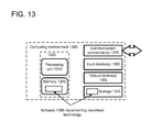
- FIG. 13 illustrates a generalized example of a suitable computing environment 1300 in which the described technologies can be implemented.
- the computing environment 1300 is not intended to suggest any limitation as to scope of use or functionality, as the technologies may be implemented in diverse general-purpose or special-purpose computing environments.
- the computing environment 1300 includes at least one processing unit 1310 coupled to memory 1320 .
- this basic configuration 1330 is included within a dashed line.
- the processing unit 1310 executes computer-executable instructions. In a multi-processing system, multiple processing units execute computer-executable instructions to increase processing power.
- the memory 1320 may be non-transitory memory, such as volatile memory (e.g., registers, cache, RAM), non-volatile memory (e.g., ROM, EEPROM, flash memory, etc.), or some combination of the two.
- the memory 1320 can store software 1380 implementing any of the technologies described herein.
- a computing environment may have additional features.
- the computing environment 1300 includes storage 1340 , one or more input devices 1350 , one or more output devices 1360 , and one or more communication connections 1370 .
- An interconnection mechanism such as a bus, controller, or network interconnects the components of the computing environment 1300 .
- operating system software provides an operating environment for other software executing in the computing environment 1300 , and coordinates activities of the components of the computing environment 1300 .
- the storage 1340 may be removable or non-removable, and includes magnetic disks, magnetic tapes or cassettes, CD-ROMs, CD-RWs, DVDs, or any other non-transitory computer-readable media which can be used to store information and which can be accessed within the computing environment 1300 .
- the storage 1340 can store software 1380 containing instructions for any of the technologies described herein.
- the input device(s) 1350 may be a touch input device such as a keyboard, touchscreen, mouse, pen, or trackball, a voice input device, a scanning device, or another device that provides input to the computing environment 1300 .
- the output device(s) 1360 may be a display, printer, speaker, CD- or DVD-writer, or another device that provides output from the computing environment 1300 .
- Some input/output devices, such as a touchscreen, may include both input and output functionality.
- the communication connection(s) 1370 enable communication over a communication mechanism to another computing entity.
- the communication mechanism conveys information such as computer-executable instructions, audio/video or other information, or other data.
- communication mechanisms include wired or wireless techniques implemented with an electrical, optical, RF, infrared, acoustic, or other carrier.
- program modules include routines, programs, libraries, objects, classes, components, data structures, etc., that perform particular tasks or implement particular abstract data types.
- the functionality of the program modules may be combined or split between program modules as desired in various embodiments.
- Computer-executable instructions for program modules may be executed within a local or distributed computing environment.
- Any of the storing actions described herein can be implemented by storing in one or more computer-readable media (e.g., non-transitory computer-readable storage media or other tangible media). Any of the things described as stored can be stored in one or more computer-readable media (e.g., computer-readable storage media or other tangible media).
- computer-readable media e.g., non-transitory computer-readable storage media or other tangible media.
- Any of the methods described herein can be implemented by computer-executable instructions in (e.g., encoded on) one or more computer-readable media (e.g., non-transitory computer-readable storage media or other tangible media). Such instructions can cause a computer to perform the method.
- the technologies described herein can be implemented in a variety of programming languages.
- Any of the methods described herein can be implemented by computer-executable instructions stored in one or more non-transitory computer-readable storage devices (e.g., memory, CD-ROM, CD-RW, DVD, or the like). Such instructions can cause a computer to perform the method.
- non-transitory computer-readable storage devices e.g., memory, CD-ROM, CD-RW, DVD, or the like.
- FIG. 14 illustrates a generalized example of a suitable implementation environment 1400 in which described embodiments, techniques, and technologies may be implemented.
- various types of services are provided by a cloud 1410 .
- the cloud 1410 can comprise a collection of computing devices, which may be located centrally or distributed, that provide cloud-based services to various types of users and devices connected via a network such as the Internet.
- the cloud computing environment 1400 can be used in different ways to accomplish computing tasks. For example, with reference to the described techniques and tools, some tasks, such as processing user input and presenting a user interface, can be performed on a local computing device, while other tasks, such as storage of data to be used in subsequent processing, can be performed elsewhere in the cloud.
- the cloud 1410 provides services for connected devices with a variety of screen capabilities 1420 A-N.
- Connected device 1420 A represents a device with a mid-sized screen.
- connected device 1420 A could be a personal computer such as desktop computer, laptop, notebook, netbook, or the like.
- Connected device 1420 B represents a device with a small-sized screen.
- connected device 1420 B could be a mobile phone, smart phone, personal digital assistant, tablet computer, and the like.
- Connected device 1420 N represents a device with a large screen.
- connected device 1420 N could be a television (e.g., a smart television) or another device connected to a television or projector screen (e.g., a set-top box or gaming console).
- a variety of services can be provided by the cloud 1410 through one or more service providers (not shown).
- the cloud 1410 can provide services related to mobile computing to one or more of the various connected devices 1420 A-N.
- Cloud services can be customized to the screen size, display capability, or other functionality of the particular connected device (e.g., connected devices 1420 A-N).
- cloud services can be customized for mobile devices by taking into account the screen size, input devices, and communication bandwidth limitations typically associated with mobile devices.
- FIG. 15 is a system diagram depicting an exemplary mobile device 1500 including a variety of optional hardware and software components, shown generally at 1502 . Any components 1502 in the mobile device can communicate with any other component, although not all connections are shown, for ease of illustration.
- the mobile device can be any of a variety of computing devices (e.g., cell phone, smartphone, handheld computer, personal digital assistant (PDA), etc.) and can allow wireless two-way communications with one or more mobile communications networks 1504 , such as a cellular or satellite network.
- PDA personal digital assistant
- the illustrated mobile device can include a controller or processor 1510 (e.g., signal processor, microprocessor, ASIC, or other control and processing logic circuitry) for performing such tasks as signal coding, data processing, input/output processing, power control, and/or other functions.
- An operating system 1512 can control the allocation and usage of the components 1502 and support for one or more application programs 1514 .
- the application programs can include common mobile computing applications (e.g., include email applications, calendars, contact managers, web browsers, messaging applications), or any other computing application.
- the mobile computing applications can further include an application for performing any of the disclosed techniques.
- the illustrated mobile device can include memory 1520 .
- Memory 1520 can include non-removable memory 1522 and/or removable memory 1524 .
- the non-removable memory 1522 can include RAM, ROM, flash memory, a disk drive, or other well-known non-transitory storage technologies.
- the removable memory 1524 can include flash memory or a Subscriber Identity Module (SIM) card, which is well known in GSM communication systems, or other well-known non-transitory storage technologies, such as smart cards.
- SIM Subscriber Identity Module
- the memory 1520 can be used for storing data and/or code for running the operating system 1512 and the application programs 1514 , including an application program for performing any of the disclosed techniques.
- Example data can include web pages, text, images, sound files, video data, or other data sets to be sent to and/or received from one or more network servers or other mobile devices via one or more wired or wireless networks.
- the memory 1520 can be used to store a subscriber identifier, such as an International Mobile Subscriber Identity (IMSI), and an equipment identifier, such as an International Mobile Equipment Identifier (IMEI).
- IMSI International Mobile Subscriber Identity
- IMEI International Mobile Equipment Identifier
- the mobile device can support one or more input devices 1530 , such as a touchscreen 1532 , microphone 1534 , camera 1536 , physical keyboard 1538 and/or trackball 1540 and one or more output devices 1550 , such as a speaker 1552 and a display device 1554 .
- input devices 1530 such as a touchscreen 1532 , microphone 1534 , camera 1536 , physical keyboard 1538 and/or trackball 1540
- output devices 1550 such as a speaker 1552 and a display device 1554 .
- Other possible output devices can include a piezoelectric or other haptic output device. Some devices can serve more than one input/output function.
- touchscreen 1532 and display 1554 can be combined in a single input/output device.
- Touchscreen 1532 can accept input in different ways. For example, capacitive touchscreens can detect touch input when an object (e.g., a fingertip) distorts or interrupts an electrical current running across the surface. As another example, resistive touchscreens can detect touch input when a pressure from an object (e.g., a fingertip or stylus) causes a compression of the physical surface. As another example, touchscreens can use optical sensors to detect touch input when beams from the optical sensors are interrupted. Physical contact with the surface of the screen is not necessary for input to be detected by some touchscreens.
- object e.g., a fingertip
- resistive touchscreens can detect touch input when a pressure from an object (e.g., a fingertip or stylus) causes a compression of the physical surface.
- touchscreens can use optical sensors to detect touch input when beams from the optical sensors are interrupted. Physical contact with the surface of the screen is not necessary for input to be detected by some touchscreens.
- a wireless modem 1560 can be coupled to an antenna (not shown) and can support two-way communications between the processor 1510 and external devices, as is well understood in the art.
- the modem 1560 is shown generically and can include a cellular modem for communicating with the mobile communication network 1504 and/or other radio-based modems (e.g., Bluetooth or Wi-Fi).
- the wireless modem 1560 is typically configured for communication with one or more cellular networks, such as a GSM network for data and voice communications within a single cellular network, between cellular networks, or between the mobile device and a public switched telephone network (PSTN).
- GSM Global System for Mobile communications
- PSTN public switched telephone network
- the mobile device can further include at least one input/output port 1580 , a power supply 1582 , a satellite navigation system receiver 1584 , such as a global positioning system (GPS) receiver, an accelerometer 1586 , a transceiver 1588 (for wirelessly transmitting analog or digital signals) and/or a physical connector 1590 , which can be a USB port, IEEE 1394 (FireWire) port, and/or RS-232 port.
- GPS global positioning system
- the illustrated components 1502 are not required or all-inclusive, as components can be deleted and other components can be added.
- Described techniques and tools can be used in different display orientations, such as portrait orientation or landscape orientation. Changes in display orientation can occur, for example, where a UI has been configured (e.g., by user preference) to be oriented in landscape fashion, or where a user has physically rotated a device.
- One or more sensors e.g., an accelerometer
- UI elements e.g., a web page
- a reorientation e.g., a new effective width of the display area, interpreting directions of user interactions differently, etc.
- distortion effects can be adjusted, such as by compressing UI elements in a horizontal dimension instead of a vertical dimension, to account for display reorientation.
- adjustments are not required. For example, if a display area has equal height and width, reorientation of the display area to a landscape orientation will not change the effective width of the display area.
Abstract
Description
(region_to_be_compressed−position_delta)/region_to_be_compressed,
which reduces to:
1−(position_delta/region_to_be_compressed).
Center=size_of_viewport*compression_percent+compression_offset.
Claims (20)
Priority Applications (1)
| Application Number | Priority Date | Filing Date | Title |
|---|---|---|---|
| US13/089,252 US8863039B2 (en) | 2011-04-18 | 2011-04-18 | Multi-dimensional boundary effects |
Applications Claiming Priority (1)
| Application Number | Priority Date | Filing Date | Title |
|---|---|---|---|
| US13/089,252 US8863039B2 (en) | 2011-04-18 | 2011-04-18 | Multi-dimensional boundary effects |
Publications (2)
| Publication Number | Publication Date |
|---|---|
| US20120266109A1 US20120266109A1 (en) | 2012-10-18 |
| US8863039B2 true US8863039B2 (en) | 2014-10-14 |
Family
ID=47007345
Family Applications (1)
| Application Number | Title | Priority Date | Filing Date |
|---|---|---|---|
| US13/089,252 Active 2032-10-30 US8863039B2 (en) | 2011-04-18 | 2011-04-18 | Multi-dimensional boundary effects |
Country Status (1)
| Country | Link |
|---|---|
| US (1) | US8863039B2 (en) |
Cited By (11)
| Publication number | Priority date | Publication date | Assignee | Title |
|---|---|---|---|---|
| US20140285507A1 (en) * | 2013-03-19 | 2014-09-25 | Canon Kabushiki Kaisha | Display control device, display control method, and computer-readable storage medium |
| US10283082B1 (en) | 2016-10-29 | 2019-05-07 | Dvir Gassner | Differential opacity position indicator |
| US10474344B2 (en) * | 2013-08-21 | 2019-11-12 | Samsung Electronics Co., Ltd. | Method, apparatus and recording medium for a scrolling screen |
| US10497161B1 (en) | 2018-06-08 | 2019-12-03 | Curious Company, LLC | Information display by overlay on an object |
| US20200082602A1 (en) * | 2018-09-06 | 2020-03-12 | Curious Company, LLC | Dynamic display of hidden information |
| US10650600B2 (en) | 2018-07-10 | 2020-05-12 | Curious Company, LLC | Virtual path display |
| CN111475088A (en) * | 2019-01-23 | 2020-07-31 | 百度在线网络技术(北京)有限公司 | Page scrolling method and device, storage medium and terminal equipment |
| US10818088B2 (en) | 2018-07-10 | 2020-10-27 | Curious Company, LLC | Virtual barrier objects |
| US10872584B2 (en) | 2019-03-14 | 2020-12-22 | Curious Company, LLC | Providing positional information using beacon devices |
| US10970935B2 (en) | 2018-12-21 | 2021-04-06 | Curious Company, LLC | Body pose message system |
| US10991162B2 (en) | 2018-12-04 | 2021-04-27 | Curious Company, LLC | Integrating a user of a head-mounted display into a process |
Families Citing this family (16)
| Publication number | Priority date | Publication date | Assignee | Title |
|---|---|---|---|---|
| KR101872865B1 (en) * | 2012-03-05 | 2018-08-02 | 엘지전자 주식회사 | Electronic Device And Method Of Controlling The Same |
| US11386257B2 (en) | 2012-10-15 | 2022-07-12 | Amaze Software, Inc. | Efficient manipulation of surfaces in multi-dimensional space using energy agents |
| US20190005146A1 (en) * | 2012-10-15 | 2019-01-03 | Famous Industries, Inc. | Manipulating Virtual Camera Dolly in Multi-Dimensional Space to Produce Visual Effect |
| WO2014063834A1 (en) * | 2012-10-22 | 2014-05-01 | Telefónica, S.A. | A computed implemented method and electronic device for providing visual feedback to a user when the edge of an object has been reached |
| JP6018474B2 (en) * | 2012-10-23 | 2016-11-02 | 任天堂株式会社 | Program, information processing apparatus, information processing method, and information processing system |
| US9696867B2 (en) * | 2013-01-15 | 2017-07-04 | Leap Motion, Inc. | Dynamic user interactions for display control and identifying dominant gestures |
| US10346025B2 (en) * | 2013-02-05 | 2019-07-09 | Microsoft Technology Licensing, Llc | Friction field for fluid margin panning in a webpage |
| TW201433971A (en) * | 2013-02-20 | 2014-09-01 | Phoenix Tech Ltd | Method of indicating an edge of an electronic document |
| US9329764B2 (en) * | 2013-03-15 | 2016-05-03 | Google Inc. | Overscroll visual effects |
| US9274701B2 (en) | 2013-07-10 | 2016-03-01 | Nvidia Corporation | Method and system for a creased paper effect on page limits |
| US20150066360A1 (en) * | 2013-09-04 | 2015-03-05 | Honda Motor Co., Ltd. | Dashboard display navigation |
| US20150089454A1 (en) * | 2013-09-25 | 2015-03-26 | Kobo Incorporated | Overscroll stretch animation |
| US10050949B2 (en) * | 2015-03-23 | 2018-08-14 | Amazon Technologies, Inc. | Accessing a secure network using a streaming device |
| EP3239811B1 (en) * | 2016-04-29 | 2021-11-03 | Nokia Technologies Oy | A method, apparatus or computer program for user control of access to displayed content |
| US10175941B2 (en) * | 2016-05-24 | 2019-01-08 | Oracle International Corporation | Audio feedback for continuous scrolled content |
| CN114911406B (en) * | 2022-06-01 | 2023-10-17 | 北京字节跳动网络技术有限公司 | Dynamic effect generation method, dynamic effect generation device, dynamic effect generation medium and dynamic effect generation equipment |
Citations (81)
| Publication number | Priority date | Publication date | Assignee | Title |
|---|---|---|---|---|
| US5581670A (en) | 1993-07-21 | 1996-12-03 | Xerox Corporation | User interface having movable sheet with click-through tools |
| US5860073A (en) | 1995-07-17 | 1999-01-12 | Microsoft Corporation | Style sheets for publishing system |
| US5874961A (en) | 1997-03-19 | 1999-02-23 | International Business Machines Corporation | Scroll bar amplification apparatus and method |
| US6028593A (en) | 1995-12-01 | 2000-02-22 | Immersion Corporation | Method and apparatus for providing simulated physical interactions within computer generated environments |
| US6157381A (en) | 1997-11-18 | 2000-12-05 | International Business Machines Corporation | Computer system, user interface component and method utilizing non-linear scroll bar |
| US6246406B1 (en) | 1998-02-06 | 2001-06-12 | Sun Microsystems, Inc. | Techniques for navigating layers of a user interface |
| US6366302B1 (en) | 1998-12-22 | 2002-04-02 | Motorola, Inc. | Enhanced graphic user interface for mobile radiotelephones |
| US20020135602A1 (en) | 2001-03-20 | 2002-09-26 | Jeffery Davis | Scrolling method using screen pointing device |
| US6469718B1 (en) | 1997-08-22 | 2002-10-22 | Sony Corporation | Recording medium retaining data for menu control, menu control method and apparatus |
| US20030095135A1 (en) | 2001-05-02 | 2003-05-22 | Kaasila Sampo J. | Methods, systems, and programming for computer display of images, text, and/or digital content |
| KR100400208B1 (en) | 1996-10-31 | 2003-12-31 | 삼성전자주식회사 | Apparatus for generating multi-step background picture in video game with real image background |
| US6714213B1 (en) | 1999-10-08 | 2004-03-30 | General Electric Company | System and method for providing interactive haptic collision detection |
| US20050149551A1 (en) | 2004-01-05 | 2005-07-07 | Jeffrey Fong | Systems and methods for co-axial navigation of a user interface |
| US6985149B2 (en) | 2002-07-31 | 2006-01-10 | Silicon Graphics, Inc. | System and method for decoupling the user interface and application window in a graphics application |
| US20060053048A1 (en) | 2004-09-03 | 2006-03-09 | Whenu.Com | Techniques for remotely delivering shaped display presentations such as advertisements to computing platforms over information communications networks |
| US7032181B1 (en) | 2002-06-18 | 2006-04-18 | Good Technology, Inc. | Optimized user interface for small screen devices |
| US20060095360A1 (en) | 1996-01-16 | 2006-05-04 | The Nasdaq Stock Market, Inc., A Delaware Corporation | Media wall for displaying financial information |
| US20060143577A1 (en) | 2004-12-24 | 2006-06-29 | Kuan-Hong Hsieh | Graphical user interface for manipulating graphic images and method thereof |
| US20060161863A1 (en) | 2004-11-16 | 2006-07-20 | Gallo Anthony C | Cellular user interface |
| US20060174214A1 (en) | 2003-08-13 | 2006-08-03 | Mckee Timothy P | System and method for navigation of content in multiple display regions |
| US20060210958A1 (en) | 2005-03-21 | 2006-09-21 | Microsoft Corporation | Gesture training |
| US20060277469A1 (en) | 2004-06-25 | 2006-12-07 | Chaudhri Imran A | Preview and installation of user interface elements in a display environment |
| WO2007017784A2 (en) | 2005-08-09 | 2007-02-15 | Koninklijke Philips Electronics N.V. | Scroll method with contextual scroll rate and feedback |
| US20070079246A1 (en) | 2005-09-08 | 2007-04-05 | Gilles Morillon | Method of selection of a button in a graphical bar, and receiver implementing the method |
| US7203901B2 (en) | 2002-11-27 | 2007-04-10 | Microsoft Corporation | Small form factor web browsing |
| US20070132789A1 (en) | 2005-12-08 | 2007-06-14 | Bas Ording | List scrolling in response to moving contact over list of index symbols |
| US20070150830A1 (en) | 2005-12-23 | 2007-06-28 | Bas Ording | Scrolling list with floating adjacent index symbols |
| US20070188444A1 (en) | 2006-02-10 | 2007-08-16 | Microsoft Corporation | Physical-virtual interpolation |
| US20070245260A1 (en) | 2006-04-12 | 2007-10-18 | Laas & Sonder Pty Ltd | Method and system for organizing and displaying data |
| US20080016471A1 (en) | 2006-07-14 | 2008-01-17 | Samsung Electronics Co., Ltd. | Electronic device for providing 3D user interface and method of providing a 3D user interface |
| US7337392B2 (en) | 2003-01-27 | 2008-02-26 | Vincent Wen-Jeng Lue | Method and apparatus for adapting web contents to different display area dimensions |
| US20080165210A1 (en) | 2007-01-07 | 2008-07-10 | Andrew Platzer | Animations |
| US20080168349A1 (en) | 2007-01-07 | 2008-07-10 | Lamiraux Henri C | Portable Electronic Device, Method, and Graphical User Interface for Displaying Electronic Documents and Lists |
| US20080178126A1 (en) | 2007-01-24 | 2008-07-24 | Microsoft Corporation | Gesture recognition interactive feedback |
| US20080215995A1 (en) | 2007-01-17 | 2008-09-04 | Heiner Wolf | Model based avatars for virtual presence |
| US7428709B2 (en) | 2005-04-13 | 2008-09-23 | Apple Inc. | Multiple-panel scrolling |
| US7430712B2 (en) | 2005-03-16 | 2008-09-30 | Ameriprise Financial, Inc. | System and method for dynamically resizing embeded web page content |
| US7461353B2 (en) | 2000-06-12 | 2008-12-02 | Gary Rohrabaugh | Scalable display of internet content on mobile devices |
| US20080307361A1 (en) | 2007-06-08 | 2008-12-11 | Apple Inc. | Selection user interface |
| US7469381B2 (en) | 2007-01-07 | 2008-12-23 | Apple Inc. | List scrolling and document translation, scaling, and rotation on a touch-screen display |
| US20090007017A1 (en) | 2007-06-29 | 2009-01-01 | Freddy Allen Anzures | Portable multifunction device with animated user interface transitions |
| US20090070711A1 (en) | 2007-09-04 | 2009-03-12 | Lg Electronics Inc. | Scrolling method of mobile terminal |
| US20090125836A1 (en) | 2006-04-20 | 2009-05-14 | Akihiro Yamamoto | Image output device |
| US20090125824A1 (en) | 2007-11-12 | 2009-05-14 | Microsoft Corporation | User interface with physics engine for natural gestural control |
| US20090138815A1 (en) | 2007-11-26 | 2009-05-28 | Palm, Inc. | Enhancing visual continuity in scrolling operations |
| US20090204928A1 (en) | 2008-02-11 | 2009-08-13 | Idean Enterprise Oy | Layer-based user interface |
| US20090231271A1 (en) | 2008-03-12 | 2009-09-17 | Immersion Corporation | Haptically Enabled User Interface |
| US20090284478A1 (en) | 2008-05-15 | 2009-11-19 | Microsoft Corporation | Multi-Contact and Single-Contact Input |
| US20090292989A1 (en) | 2008-05-23 | 2009-11-26 | Microsoft Corporation | Panning content utilizing a drag operation |
| US7634789B2 (en) | 2000-08-14 | 2009-12-15 | Corporate Media Partners | System and method for displaying advertising in an interactive program guide |
| US7636755B2 (en) | 2002-11-21 | 2009-12-22 | Aol Llc | Multiple avatar personalities |
| US20090315839A1 (en) | 2008-06-24 | 2009-12-24 | Microsoft Corporation | Physics simulation-based interaction for surface computing |
| US20090327938A1 (en) | 2001-04-09 | 2009-12-31 | Microsoft Corporation | Animation on object user interface |
| US20100009747A1 (en) | 2008-07-14 | 2010-01-14 | Microsoft Corporation | Programming APIS for an Extensible Avatar System |
| US20100011316A1 (en) | 2008-01-17 | 2010-01-14 | Can Sar | System for intelligent automated layout and management of interactive windows |
| US20100026698A1 (en) | 2008-08-01 | 2010-02-04 | Microsoft Corporation | Avatar items and animations |
| US7663620B2 (en) | 2005-12-05 | 2010-02-16 | Microsoft Corporation | Accessing 2D graphic content using axonometric layer views |
| US20100039447A1 (en) | 2008-08-18 | 2010-02-18 | Sony Corporation | Image processing apparatus, image processing method, and program |
| US20100073380A1 (en) | 2008-09-19 | 2010-03-25 | Pure Digital Technologies, Inc. | Method of operating a design generator for personalization of electronic devices |
| US20100083165A1 (en) | 2008-09-29 | 2010-04-01 | Microsoft Corporation | Panoramic graphical user interface |
| US7690997B2 (en) | 2005-10-14 | 2010-04-06 | Leviathan Entertainment, Llc | Virtual environment with formalized inter-character relationships |
| US7698658B2 (en) | 2004-03-19 | 2010-04-13 | Sony Corporation | Display controlling apparatus, display controlling method, and recording medium |
| US7707494B2 (en) | 2004-08-06 | 2010-04-27 | Canon Kabushiki Kaisha | Information processing apparatus, control method therefor, and program |
| US20100107068A1 (en) | 2008-10-23 | 2010-04-29 | Butcher Larry R | User Interface with Parallax Animation |
| US7724242B2 (en) | 2004-08-06 | 2010-05-25 | Touchtable, Inc. | Touch driven method and apparatus to integrate and display multiple image layers forming alternate depictions of same subject matter |
| US20100137031A1 (en) | 2008-12-01 | 2010-06-03 | Research In Motion Limited | Portable electronic device and method of controlling same |
| US20100134425A1 (en) | 2008-12-03 | 2010-06-03 | Microsoft Corporation | Manipulation of list on a multi-touch display |
| US7735004B2 (en) | 2004-01-30 | 2010-06-08 | Canon Kabushiki Kaisha | Layout control method, layout control apparatus, and layout control program |
| US20100175027A1 (en) | 2009-01-06 | 2010-07-08 | Microsoft Corporation | Non-uniform scrolling |
| US7779360B1 (en) | 2007-04-10 | 2010-08-17 | Google Inc. | Map user interface |
| US20110055752A1 (en) | 2009-06-04 | 2011-03-03 | Rubinstein Jonathan J | Method and Apparatus for Displaying and Auto-Correcting an Over-Scroll State on a Computing Device |
| US20110078597A1 (en) * | 2009-09-25 | 2011-03-31 | Peter William Rapp | Device, Method, and Graphical User Interface for Manipulation of User Interface Objects with Activation Regions |
| US20110080351A1 (en) | 2009-10-07 | 2011-04-07 | Research In Motion Limited | method of controlling touch input on a touch-sensitive display when a display element is active and a portable electronic device configured for the same |
| US20110093812A1 (en) | 2009-10-21 | 2011-04-21 | Microsoft Corporation | Displaying lists as reacting against barriers |
| US20110090255A1 (en) | 2009-10-16 | 2011-04-21 | Wilson Diego A | Content boundary signaling techniques |
| US20110107264A1 (en) | 2009-10-30 | 2011-05-05 | Motorola, Inc. | Method and Device for Enhancing Scrolling Operations in a Display Device |
| US20110181527A1 (en) * | 2010-01-26 | 2011-07-28 | Jay Christopher Capela | Device, Method, and Graphical User Interface for Resizing Objects |
| US20110202834A1 (en) | 2010-02-12 | 2011-08-18 | Microsoft Corporation | Visual motion feedback for user interface |
| US20110199318A1 (en) | 2010-02-12 | 2011-08-18 | Microsoft Corporation | Multi-layer user interface with flexible parallel movement |
| US8113951B2 (en) | 2006-11-15 | 2012-02-14 | Microsoft Corporation | Achievement incentives within a console-based gaming environment |
| US8127246B2 (en) | 2007-10-01 | 2012-02-28 | Apple Inc. | Varying user interface element based on movement |
-
2011
- 2011-04-18 US US13/089,252 patent/US8863039B2/en active Active
Patent Citations (88)
| Publication number | Priority date | Publication date | Assignee | Title |
|---|---|---|---|---|
| US5581670A (en) | 1993-07-21 | 1996-12-03 | Xerox Corporation | User interface having movable sheet with click-through tools |
| US5860073A (en) | 1995-07-17 | 1999-01-12 | Microsoft Corporation | Style sheets for publishing system |
| US6028593A (en) | 1995-12-01 | 2000-02-22 | Immersion Corporation | Method and apparatus for providing simulated physical interactions within computer generated environments |
| US20060095360A1 (en) | 1996-01-16 | 2006-05-04 | The Nasdaq Stock Market, Inc., A Delaware Corporation | Media wall for displaying financial information |
| KR100400208B1 (en) | 1996-10-31 | 2003-12-31 | 삼성전자주식회사 | Apparatus for generating multi-step background picture in video game with real image background |
| US5874961A (en) | 1997-03-19 | 1999-02-23 | International Business Machines Corporation | Scroll bar amplification apparatus and method |
| US6469718B1 (en) | 1997-08-22 | 2002-10-22 | Sony Corporation | Recording medium retaining data for menu control, menu control method and apparatus |
| US6157381A (en) | 1997-11-18 | 2000-12-05 | International Business Machines Corporation | Computer system, user interface component and method utilizing non-linear scroll bar |
| US6246406B1 (en) | 1998-02-06 | 2001-06-12 | Sun Microsystems, Inc. | Techniques for navigating layers of a user interface |
| US6366302B1 (en) | 1998-12-22 | 2002-04-02 | Motorola, Inc. | Enhanced graphic user interface for mobile radiotelephones |
| US6714213B1 (en) | 1999-10-08 | 2004-03-30 | General Electric Company | System and method for providing interactive haptic collision detection |
| US7461353B2 (en) | 2000-06-12 | 2008-12-02 | Gary Rohrabaugh | Scalable display of internet content on mobile devices |
| US20110231782A1 (en) * | 2000-06-12 | 2011-09-22 | Softview L.L.C. | Scalable Display of Internet Content on Mobile Devices |
| US7634789B2 (en) | 2000-08-14 | 2009-12-15 | Corporate Media Partners | System and method for displaying advertising in an interactive program guide |
| US20020135602A1 (en) | 2001-03-20 | 2002-09-26 | Jeffery Davis | Scrolling method using screen pointing device |
| US20090327938A1 (en) | 2001-04-09 | 2009-12-31 | Microsoft Corporation | Animation on object user interface |
| US20030095135A1 (en) | 2001-05-02 | 2003-05-22 | Kaasila Sampo J. | Methods, systems, and programming for computer display of images, text, and/or digital content |
| US7032181B1 (en) | 2002-06-18 | 2006-04-18 | Good Technology, Inc. | Optimized user interface for small screen devices |
| US6985149B2 (en) | 2002-07-31 | 2006-01-10 | Silicon Graphics, Inc. | System and method for decoupling the user interface and application window in a graphics application |
| US7636755B2 (en) | 2002-11-21 | 2009-12-22 | Aol Llc | Multiple avatar personalities |
| US7203901B2 (en) | 2002-11-27 | 2007-04-10 | Microsoft Corporation | Small form factor web browsing |
| US7337392B2 (en) | 2003-01-27 | 2008-02-26 | Vincent Wen-Jeng Lue | Method and apparatus for adapting web contents to different display area dimensions |
| US20060174214A1 (en) | 2003-08-13 | 2006-08-03 | Mckee Timothy P | System and method for navigation of content in multiple display regions |
| US20050149551A1 (en) | 2004-01-05 | 2005-07-07 | Jeffrey Fong | Systems and methods for co-axial navigation of a user interface |
| US7698654B2 (en) | 2004-01-05 | 2010-04-13 | Microsoft Corporation | Systems and methods for co-axial navigation of a user interface |
| US7735004B2 (en) | 2004-01-30 | 2010-06-08 | Canon Kabushiki Kaisha | Layout control method, layout control apparatus, and layout control program |
| US7698658B2 (en) | 2004-03-19 | 2010-04-13 | Sony Corporation | Display controlling apparatus, display controlling method, and recording medium |
| US20060277469A1 (en) | 2004-06-25 | 2006-12-07 | Chaudhri Imran A | Preview and installation of user interface elements in a display environment |
| US7707494B2 (en) | 2004-08-06 | 2010-04-27 | Canon Kabushiki Kaisha | Information processing apparatus, control method therefor, and program |
| US7724242B2 (en) | 2004-08-06 | 2010-05-25 | Touchtable, Inc. | Touch driven method and apparatus to integrate and display multiple image layers forming alternate depictions of same subject matter |
| US20060053048A1 (en) | 2004-09-03 | 2006-03-09 | Whenu.Com | Techniques for remotely delivering shaped display presentations such as advertisements to computing platforms over information communications networks |
| US20060161863A1 (en) | 2004-11-16 | 2006-07-20 | Gallo Anthony C | Cellular user interface |
| US20060143577A1 (en) | 2004-12-24 | 2006-06-29 | Kuan-Hong Hsieh | Graphical user interface for manipulating graphic images and method thereof |
| US7430712B2 (en) | 2005-03-16 | 2008-09-30 | Ameriprise Financial, Inc. | System and method for dynamically resizing embeded web page content |
| US20060210958A1 (en) | 2005-03-21 | 2006-09-21 | Microsoft Corporation | Gesture training |
| US7428709B2 (en) | 2005-04-13 | 2008-09-23 | Apple Inc. | Multiple-panel scrolling |
| WO2007017784A2 (en) | 2005-08-09 | 2007-02-15 | Koninklijke Philips Electronics N.V. | Scroll method with contextual scroll rate and feedback |
| US20070079246A1 (en) | 2005-09-08 | 2007-04-05 | Gilles Morillon | Method of selection of a button in a graphical bar, and receiver implementing the method |
| US7690997B2 (en) | 2005-10-14 | 2010-04-06 | Leviathan Entertainment, Llc | Virtual environment with formalized inter-character relationships |
| US7663620B2 (en) | 2005-12-05 | 2010-02-16 | Microsoft Corporation | Accessing 2D graphic content using axonometric layer views |
| US20070132789A1 (en) | 2005-12-08 | 2007-06-14 | Bas Ording | List scrolling in response to moving contact over list of index symbols |
| US20110022985A1 (en) | 2005-12-23 | 2011-01-27 | Bas Ording | Scrolling List with Floating Adjacent Index Symbols |
| US20070150830A1 (en) | 2005-12-23 | 2007-06-28 | Bas Ording | Scrolling list with floating adjacent index symbols |
| US7958456B2 (en) | 2005-12-23 | 2011-06-07 | Apple Inc. | Scrolling list with floating adjacent index symbols |
| US20070188444A1 (en) | 2006-02-10 | 2007-08-16 | Microsoft Corporation | Physical-virtual interpolation |
| US20070245260A1 (en) | 2006-04-12 | 2007-10-18 | Laas & Sonder Pty Ltd | Method and system for organizing and displaying data |
| US20090125836A1 (en) | 2006-04-20 | 2009-05-14 | Akihiro Yamamoto | Image output device |
| US20080016471A1 (en) | 2006-07-14 | 2008-01-17 | Samsung Electronics Co., Ltd. | Electronic device for providing 3D user interface and method of providing a 3D user interface |
| US8113951B2 (en) | 2006-11-15 | 2012-02-14 | Microsoft Corporation | Achievement incentives within a console-based gaming environment |
| US7469381B2 (en) | 2007-01-07 | 2008-12-23 | Apple Inc. | List scrolling and document translation, scaling, and rotation on a touch-screen display |
| US20080165210A1 (en) | 2007-01-07 | 2008-07-10 | Andrew Platzer | Animations |
| US8223134B1 (en) | 2007-01-07 | 2012-07-17 | Apple Inc. | Portable electronic device, method, and graphical user interface for displaying electronic lists and documents |
| US20090073194A1 (en) | 2007-01-07 | 2009-03-19 | Bas Ording | Device, Method, and Graphical User Interface for List Scrolling on a Touch-Screen Display |
| US20080168349A1 (en) | 2007-01-07 | 2008-07-10 | Lamiraux Henri C | Portable Electronic Device, Method, and Graphical User Interface for Displaying Electronic Documents and Lists |
| US20080215995A1 (en) | 2007-01-17 | 2008-09-04 | Heiner Wolf | Model based avatars for virtual presence |
| US20080178126A1 (en) | 2007-01-24 | 2008-07-24 | Microsoft Corporation | Gesture recognition interactive feedback |
| US7779360B1 (en) | 2007-04-10 | 2010-08-17 | Google Inc. | Map user interface |
| US20080307361A1 (en) | 2007-06-08 | 2008-12-11 | Apple Inc. | Selection user interface |
| US20090007017A1 (en) | 2007-06-29 | 2009-01-01 | Freddy Allen Anzures | Portable multifunction device with animated user interface transitions |
| US20090070711A1 (en) | 2007-09-04 | 2009-03-12 | Lg Electronics Inc. | Scrolling method of mobile terminal |
| US8127246B2 (en) | 2007-10-01 | 2012-02-28 | Apple Inc. | Varying user interface element based on movement |
| US20090125824A1 (en) | 2007-11-12 | 2009-05-14 | Microsoft Corporation | User interface with physics engine for natural gestural control |
| US20090138815A1 (en) | 2007-11-26 | 2009-05-28 | Palm, Inc. | Enhancing visual continuity in scrolling operations |
| US20100011316A1 (en) | 2008-01-17 | 2010-01-14 | Can Sar | System for intelligent automated layout and management of interactive windows |
| US20090204928A1 (en) | 2008-02-11 | 2009-08-13 | Idean Enterprise Oy | Layer-based user interface |
| US20090231271A1 (en) | 2008-03-12 | 2009-09-17 | Immersion Corporation | Haptically Enabled User Interface |
| US20090284478A1 (en) | 2008-05-15 | 2009-11-19 | Microsoft Corporation | Multi-Contact and Single-Contact Input |
| US20090292989A1 (en) | 2008-05-23 | 2009-11-26 | Microsoft Corporation | Panning content utilizing a drag operation |
| US20090315839A1 (en) | 2008-06-24 | 2009-12-24 | Microsoft Corporation | Physics simulation-based interaction for surface computing |
| US20100009747A1 (en) | 2008-07-14 | 2010-01-14 | Microsoft Corporation | Programming APIS for an Extensible Avatar System |
| US20100026698A1 (en) | 2008-08-01 | 2010-02-04 | Microsoft Corporation | Avatar items and animations |
| US20100039447A1 (en) | 2008-08-18 | 2010-02-18 | Sony Corporation | Image processing apparatus, image processing method, and program |
| US20100073380A1 (en) | 2008-09-19 | 2010-03-25 | Pure Digital Technologies, Inc. | Method of operating a design generator for personalization of electronic devices |
| US20100083165A1 (en) | 2008-09-29 | 2010-04-01 | Microsoft Corporation | Panoramic graphical user interface |
| US20100107068A1 (en) | 2008-10-23 | 2010-04-29 | Butcher Larry R | User Interface with Parallax Animation |
| US20100137031A1 (en) | 2008-12-01 | 2010-06-03 | Research In Motion Limited | Portable electronic device and method of controlling same |
| US20100134425A1 (en) | 2008-12-03 | 2010-06-03 | Microsoft Corporation | Manipulation of list on a multi-touch display |
| US20100175027A1 (en) | 2009-01-06 | 2010-07-08 | Microsoft Corporation | Non-uniform scrolling |
| US20110055752A1 (en) | 2009-06-04 | 2011-03-03 | Rubinstein Jonathan J | Method and Apparatus for Displaying and Auto-Correcting an Over-Scroll State on a Computing Device |
| US20110078597A1 (en) * | 2009-09-25 | 2011-03-31 | Peter William Rapp | Device, Method, and Graphical User Interface for Manipulation of User Interface Objects with Activation Regions |
| US20110080351A1 (en) | 2009-10-07 | 2011-04-07 | Research In Motion Limited | method of controlling touch input on a touch-sensitive display when a display element is active and a portable electronic device configured for the same |
| US20110090255A1 (en) | 2009-10-16 | 2011-04-21 | Wilson Diego A | Content boundary signaling techniques |
| US20110093812A1 (en) | 2009-10-21 | 2011-04-21 | Microsoft Corporation | Displaying lists as reacting against barriers |
| US20110107264A1 (en) | 2009-10-30 | 2011-05-05 | Motorola, Inc. | Method and Device for Enhancing Scrolling Operations in a Display Device |
| US20110181527A1 (en) * | 2010-01-26 | 2011-07-28 | Jay Christopher Capela | Device, Method, and Graphical User Interface for Resizing Objects |
| US20110202834A1 (en) | 2010-02-12 | 2011-08-18 | Microsoft Corporation | Visual motion feedback for user interface |
| US20110199318A1 (en) | 2010-02-12 | 2011-08-18 | Microsoft Corporation | Multi-layer user interface with flexible parallel movement |
| US20110202859A1 (en) | 2010-02-12 | 2011-08-18 | Microsoft Corporation | Distortion effects to indicate location in a movable data collection |
Non-Patent Citations (27)
| Title |
|---|
| "iPhone How to: Lists," www.apple.com, visited Apr. 15, 2010, 1 page. |
| "iPhone How to: Scrolling," www.apple.com, visited Apr. 15, 2010, 1 page. |
| "iPhone How to: Viewing in Landscape," www.apple.com, visited Apr. 15, 2010, 1 page. |
| "iPhone How to: Zooming In or Out," www.apple.com, visited Apr. 15, 2010, 1 page. |
| "iPod touch Technology," www.apple.com, visited Apr. 15, 2010, 3 pages. |
| "Windows Phone 7 Series Demo," http://www.youtube.com/watch?v=MdDAeyy1H0A, 2 pp. (Feb. 12, 2010). |
| "Windows Phone 7 Series Features Video," http://www.youtube.com/watch?v=7IOTrq1z4jo, 2 pp. (Feb. 12, 2010). |
| "Zune HD Is Real, Has Multitouch Web Browsing, OLED Screen and HD Video," gizmodo.com, dated May 26, 2009, visited Apr. 15, 2010, 3 pages. |
| Baudisch et al., "Fishnet, a fisheye web browser with search term popouts: a comparative evaluation with overview and linear view," AVI 2004: Advanced Visual Interfaces Int'l Working Conference, Gallipolli, Italy, May 2004, pp. 133-140. |
| Cerney and Vance, "Gesture Recognition in Virtual Environments: A Review and Framework for Future Development," Iowa State University Human Computer Interaction Technical Report ISU-HCI-2005-01, Mar. 28, 2005, 25 pages. |
| Coyier, "Scroll/Follow Sidebar, Multiple Techniques," 4 pp. (Nov. 30, 2009). |
| Fasig, "Windows 7: Inside Multitouch," PCMag.com, dated Oct. 26, 2009, visited Apr. 15, 2010, 4 pages. |
| Final Office action from U.S. Appl. No. 12/721,418, dated Feb. 14, 2014, 22 pages. |
| Final Office action from U.S. Appl. No. 12/773,803, dated Sep. 5, 2013, 20 pages. |
| Jeff Dion, "Creating a Floating HTML Menu Using jQuery and CSS," , 8 pp. (Jun. 2008). |
| Jeff Dion, "Creating a Floating HTML Menu Using jQuery and CSS," <http://net.tutsplus.com/html-css-techniques/creating-a-floating-html-menu-using-jquery-and-css/>, 8 pp. (Jun. 2008). |
| Kiriati et al., "Introducing Windows® 7 for Developers," 417 pages, Microsoft Press (2010). |
| Kratz and Ballagas, "Gesture Recognition Using Motion Estimation on Mobile Phones," 3rd Int'l Workshop on Pervasive Mobile Interaction Devices (PERMID 2007), May 13, 2007, 5 pages. |
| McCracken, "Windows 7 Review," , 6 pages. (Oct. 19, 2009). |
| McCracken, "Windows 7 Review," <http://www.pcworld.com/printable/article/id,172602/printable.html>, 6 pages. (Oct. 19, 2009). |
| Moussa, "Combining Expert Neural Networks Using Reinforcement Feedback for Learning Primitive Grasping Behavior," IEEE Transactions on Neural Networks, vol. 15, No. 3, May 3, 2004, pp. 629-638, 10 pages. |
| Niezen and Hancke, "Gesture Recognition as Ubiquitous Input for Mobile Phones," UbiComp '08 Workshop WI- Devices that Alter Perception (DAP 2008), Sep. 21, 2008, 5 pages. |
| Office action from U.S. Appl. No. 12/721,419, dated Jun. 10, 2013, 25 pages. |
| Office action from U.S. Appl. No. 12/773,803, dated Feb. 15, 2013, 25 pages. |
| Siena, "iPhone and the Dog Ears User Experience Model," http://headrush.typepad.com/creating-passionate-users/2007/01/iphone-and-the-.html, 10 pp. (Jan. 2007). |
| Weinberg, "Exclusive: Windows Mobile 7 to Focus on Touch and Motion Gestures," http://www.etenblog.com/2008/01/09/windows-mobile-7-to-focus-on-touch-and-motion-gestures/, 38 pp. (Jan. 2008). |
| Young, "All About Touch in Windows Media Center in Windows 7," Windows Media Center Team Blog, dated Sep. 15, 2009, visited Apr. 15, 2010, 6 pages. |
Cited By (26)
| Publication number | Priority date | Publication date | Assignee | Title |
|---|---|---|---|---|
| US9685143B2 (en) * | 2013-03-19 | 2017-06-20 | Canon Kabushiki Kaisha | Display control device, display control method, and computer-readable storage medium for changing a representation of content displayed on a display screen |
| US20140285507A1 (en) * | 2013-03-19 | 2014-09-25 | Canon Kabushiki Kaisha | Display control device, display control method, and computer-readable storage medium |
| US10474344B2 (en) * | 2013-08-21 | 2019-11-12 | Samsung Electronics Co., Ltd. | Method, apparatus and recording medium for a scrolling screen |
| US10283082B1 (en) | 2016-10-29 | 2019-05-07 | Dvir Gassner | Differential opacity position indicator |
| US10497161B1 (en) | 2018-06-08 | 2019-12-03 | Curious Company, LLC | Information display by overlay on an object |
| US11282248B2 (en) | 2018-06-08 | 2022-03-22 | Curious Company, LLC | Information display by overlay on an object |
| US10650600B2 (en) | 2018-07-10 | 2020-05-12 | Curious Company, LLC | Virtual path display |
| US10818088B2 (en) | 2018-07-10 | 2020-10-27 | Curious Company, LLC | Virtual barrier objects |
| US10636197B2 (en) * | 2018-09-06 | 2020-04-28 | Curious Company, LLC | Dynamic display of hidden information |
| US10861239B2 (en) * | 2018-09-06 | 2020-12-08 | Curious Company, LLC | Presentation of information associated with hidden objects |
| US11238666B2 (en) | 2018-09-06 | 2022-02-01 | Curious Company, LLC | Display of an occluded object in a hybrid-reality system |
| US20200082629A1 (en) * | 2018-09-06 | 2020-03-12 | Curious Company, LLC | Controlling presentation of hidden information |
| US20200082628A1 (en) * | 2018-09-06 | 2020-03-12 | Curious Company, LLC | Presentation of information associated with hidden objects |
| US10803668B2 (en) * | 2018-09-06 | 2020-10-13 | Curious Company, LLC | Controlling presentation of hidden information |
| US20200082601A1 (en) * | 2018-09-06 | 2020-03-12 | Curious Company, LLC | Virtual manipulation of hidden objects |
| US10636216B2 (en) * | 2018-09-06 | 2020-04-28 | Curious Company, LLC | Virtual manipulation of hidden objects |
| US20220139051A1 (en) * | 2018-09-06 | 2022-05-05 | Curious Company, LLC | Creating a viewport in a hybrid-reality system |
| US10902678B2 (en) | 2018-09-06 | 2021-01-26 | Curious Company, LLC | Display of hidden information |
| US20200082602A1 (en) * | 2018-09-06 | 2020-03-12 | Curious Company, LLC | Dynamic display of hidden information |
| US11055913B2 (en) | 2018-12-04 | 2021-07-06 | Curious Company, LLC | Directional instructions in an hybrid reality system |
| US10991162B2 (en) | 2018-12-04 | 2021-04-27 | Curious Company, LLC | Integrating a user of a head-mounted display into a process |
| US10970935B2 (en) | 2018-12-21 | 2021-04-06 | Curious Company, LLC | Body pose message system |
| CN111475088A (en) * | 2019-01-23 | 2020-07-31 | 百度在线网络技术(北京)有限公司 | Page scrolling method and device, storage medium and terminal equipment |
| US10955674B2 (en) | 2019-03-14 | 2021-03-23 | Curious Company, LLC | Energy-harvesting beacon device |
| US10901218B2 (en) | 2019-03-14 | 2021-01-26 | Curious Company, LLC | Hybrid reality system including beacons |
| US10872584B2 (en) | 2019-03-14 | 2020-12-22 | Curious Company, LLC | Providing positional information using beacon devices |
Also Published As
| Publication number | Publication date |
|---|---|
| US20120266109A1 (en) | 2012-10-18 |
Similar Documents
| Publication | Publication Date | Title |
|---|---|---|
| US8863039B2 (en) | Multi-dimensional boundary effects | |
| US9898180B2 (en) | Flexible touch-based scrolling | |
| US20110202834A1 (en) | Visual motion feedback for user interface | |
| US20120066638A1 (en) | Multi-dimensional auto-scrolling | |
| CA2787626C (en) | Multi-layer user interface with flexible parallel and orthogonal movement | |
| US10061997B2 (en) | Handwriting capture techniques | |
| JP5726908B2 (en) | Multi-layer user interface with flexible translation | |
| US20090002324A1 (en) | Method, Apparatus and Computer Program Product for Providing a Scrolling Mechanism for Touch Screen Devices | |
| US20120064946A1 (en) | Resizable filmstrip view of images | |
| KR20160060109A (en) | Presentation of a control interface on a touch-enabled device based on a motion or absence thereof | |
| US8762840B1 (en) | Elastic canvas visual effects in user interface | |
| WO2012164170A1 (en) | Method and apparatus for spatially indicating notifications | |
| US11928483B2 (en) | Devices, methods, and graphical user interfaces for seamless transition of user interface behaviors | |
| US20150261408A1 (en) | Multi-stage Cursor Control | |
| KR102135947B1 (en) | Method for resizing window area and electronic device for the same | |
| EP2725469B1 (en) | Information-processing device, program, information-processing method, and information-processing system | |
| US10185469B1 (en) | Method and system for advancing through a sequence of items using a touch-sensitive component | |
| KR101730381B1 (en) | Method, system and non-transitory computer-readable recording medium for controlling scroll based on context information | |
| US20170153788A1 (en) | A non-depth multiple implement input and a depth multiple implement input | |
| KR101848475B1 (en) | Method, system and non-transitory computer-readable recording medium for controlling scroll based on context information |
Legal Events
| Date | Code | Title | Description |
|---|---|---|---|
| AS | Assignment |
Owner name: MICROSOFT CORPORATION, WASHINGTON Free format text: ASSIGNMENT OF ASSIGNORS INTEREST;ASSIGNORS:LIM, YU-XI;LOBO, PHILOMENA;SIGNING DATES FROM 20110414 TO 20110415;REEL/FRAME:026688/0600 |
|
| FEPP | Fee payment procedure |
Free format text: PAYOR NUMBER ASSIGNED (ORIGINAL EVENT CODE: ASPN); ENTITY STATUS OF PATENT OWNER: LARGE ENTITY |
|
| STCF | Information on status: patent grant |
Free format text: PATENTED CASE |
|
| AS | Assignment |
Owner name: MICROSOFT TECHNOLOGY LICENSING, LLC, WASHINGTON Free format text: ASSIGNMENT OF ASSIGNORS INTEREST;ASSIGNOR:MICROSOFT CORPORATION;REEL/FRAME:034544/0001 Effective date: 20141014 |
|
| MAFP | Maintenance fee payment |
Free format text: PAYMENT OF MAINTENANCE FEE, 4TH YEAR, LARGE ENTITY (ORIGINAL EVENT CODE: M1551) Year of fee payment: 4 |
|
| MAFP | Maintenance fee payment |
Free format text: PAYMENT OF MAINTENANCE FEE, 8TH YEAR, LARGE ENTITY (ORIGINAL EVENT CODE: M1552); ENTITY STATUS OF PATENT OWNER: LARGE ENTITY Year of fee payment: 8 |