US8871391B2 - Lithium sulfide compositions for battery electrolyte and battery electrode coatings - Google Patents
Lithium sulfide compositions for battery electrolyte and battery electrode coatings Download PDFInfo
- Publication number
- US8871391B2 US8871391B2 US14/089,804 US201314089804A US8871391B2 US 8871391 B2 US8871391 B2 US 8871391B2 US 201314089804 A US201314089804 A US 201314089804A US 8871391 B2 US8871391 B2 US 8871391B2
- Authority
- US
- United States
- Prior art keywords
- shell
- lithium sulfide
- lithium
- carbon
- composite core
- Prior art date
- Legal status (The legal status is an assumption and is not a legal conclusion. Google has not performed a legal analysis and makes no representation as to the accuracy of the status listed.)
- Active
Links
Images


Classifications
-
- H—ELECTRICITY
- H01—ELECTRIC ELEMENTS
- H01M—PROCESSES OR MEANS, e.g. BATTERIES, FOR THE DIRECT CONVERSION OF CHEMICAL ENERGY INTO ELECTRICAL ENERGY
- H01M4/00—Electrodes
- H01M4/02—Electrodes composed of, or comprising, active material
- H01M4/36—Selection of substances as active materials, active masses, active liquids
- H01M4/362—Composites
- H01M4/366—Composites as layered products
-
- H—ELECTRICITY
- H01—ELECTRIC ELEMENTS
- H01M—PROCESSES OR MEANS, e.g. BATTERIES, FOR THE DIRECT CONVERSION OF CHEMICAL ENERGY INTO ELECTRICAL ENERGY
- H01M10/00—Secondary cells; Manufacture thereof
- H01M10/05—Accumulators with non-aqueous electrolyte
- H01M10/052—Li-accumulators
-
- H—ELECTRICITY
- H01—ELECTRIC ELEMENTS
- H01M—PROCESSES OR MEANS, e.g. BATTERIES, FOR THE DIRECT CONVERSION OF CHEMICAL ENERGY INTO ELECTRICAL ENERGY
- H01M10/00—Secondary cells; Manufacture thereof
- H01M10/05—Accumulators with non-aqueous electrolyte
- H01M10/056—Accumulators with non-aqueous electrolyte characterised by the materials used as electrolytes, e.g. mixed inorganic/organic electrolytes
-
- H—ELECTRICITY
- H01—ELECTRIC ELEMENTS
- H01M—PROCESSES OR MEANS, e.g. BATTERIES, FOR THE DIRECT CONVERSION OF CHEMICAL ENERGY INTO ELECTRICAL ENERGY
- H01M4/00—Electrodes
- H01M4/02—Electrodes composed of, or comprising, active material
- H01M4/13—Electrodes for accumulators with non-aqueous electrolyte, e.g. for lithium-accumulators; Processes of manufacture thereof
- H01M4/134—Electrodes based on metals, Si or alloys
-
- H—ELECTRICITY
- H01—ELECTRIC ELEMENTS
- H01M—PROCESSES OR MEANS, e.g. BATTERIES, FOR THE DIRECT CONVERSION OF CHEMICAL ENERGY INTO ELECTRICAL ENERGY
- H01M4/00—Electrodes
- H01M4/02—Electrodes composed of, or comprising, active material
- H01M4/13—Electrodes for accumulators with non-aqueous electrolyte, e.g. for lithium-accumulators; Processes of manufacture thereof
- H01M4/136—Electrodes based on inorganic compounds other than oxides or hydroxides, e.g. sulfides, selenides, tellurides, halogenides or LiCoFy
-
- H—ELECTRICITY
- H01—ELECTRIC ELEMENTS
- H01M—PROCESSES OR MEANS, e.g. BATTERIES, FOR THE DIRECT CONVERSION OF CHEMICAL ENERGY INTO ELECTRICAL ENERGY
- H01M4/00—Electrodes
- H01M4/02—Electrodes composed of, or comprising, active material
- H01M4/13—Electrodes for accumulators with non-aqueous electrolyte, e.g. for lithium-accumulators; Processes of manufacture thereof
- H01M4/139—Processes of manufacture
- H01M4/1397—Processes of manufacture of electrodes based on inorganic compounds other than oxides or hydroxides, e.g. sulfides, selenides, tellurides, halogenides or LiCoFy
-
- H—ELECTRICITY
- H01—ELECTRIC ELEMENTS
- H01M—PROCESSES OR MEANS, e.g. BATTERIES, FOR THE DIRECT CONVERSION OF CHEMICAL ENERGY INTO ELECTRICAL ENERGY
- H01M4/00—Electrodes
- H01M4/02—Electrodes composed of, or comprising, active material
- H01M4/36—Selection of substances as active materials, active masses, active liquids
- H01M4/38—Selection of substances as active materials, active masses, active liquids of elements or alloys
- H01M4/40—Alloys based on alkali metals
-
- H—ELECTRICITY
- H01—ELECTRIC ELEMENTS
- H01M—PROCESSES OR MEANS, e.g. BATTERIES, FOR THE DIRECT CONVERSION OF CHEMICAL ENERGY INTO ELECTRICAL ENERGY
- H01M4/00—Electrodes
- H01M4/02—Electrodes composed of, or comprising, active material
- H01M4/36—Selection of substances as active materials, active masses, active liquids
- H01M4/48—Selection of substances as active materials, active masses, active liquids of inorganic oxides or hydroxides
- H01M4/485—Selection of substances as active materials, active masses, active liquids of inorganic oxides or hydroxides of mixed oxides or hydroxides for inserting or intercalating light metals, e.g. LiTi2O4 or LiTi2OxFy
-
- H—ELECTRICITY
- H01—ELECTRIC ELEMENTS
- H01M—PROCESSES OR MEANS, e.g. BATTERIES, FOR THE DIRECT CONVERSION OF CHEMICAL ENERGY INTO ELECTRICAL ENERGY
- H01M4/00—Electrodes
- H01M4/02—Electrodes composed of, or comprising, active material
- H01M4/36—Selection of substances as active materials, active masses, active liquids
- H01M4/58—Selection of substances as active materials, active masses, active liquids of inorganic compounds other than oxides or hydroxides, e.g. sulfides, selenides, tellurides, halogenides or LiCoFy; of polyanionic structures, e.g. phosphates, silicates or borates
- H01M4/581—Chalcogenides or intercalation compounds thereof
- H01M4/5815—Sulfides
-
- H—ELECTRICITY
- H01—ELECTRIC ELEMENTS
- H01M—PROCESSES OR MEANS, e.g. BATTERIES, FOR THE DIRECT CONVERSION OF CHEMICAL ENERGY INTO ELECTRICAL ENERGY
- H01M4/00—Electrodes
- H01M4/02—Electrodes composed of, or comprising, active material
- H01M4/36—Selection of substances as active materials, active masses, active liquids
- H01M4/58—Selection of substances as active materials, active masses, active liquids of inorganic compounds other than oxides or hydroxides, e.g. sulfides, selenides, tellurides, halogenides or LiCoFy; of polyanionic structures, e.g. phosphates, silicates or borates
- H01M4/583—Carbonaceous material, e.g. graphite-intercalation compounds or CFx
-
- B—PERFORMING OPERATIONS; TRANSPORTING
- B82—NANOTECHNOLOGY
- B82Y—SPECIFIC USES OR APPLICATIONS OF NANOSTRUCTURES; MEASUREMENT OR ANALYSIS OF NANOSTRUCTURES; MANUFACTURE OR TREATMENT OF NANOSTRUCTURES
- B82Y30/00—Nanotechnology for materials or surface science, e.g. nanocomposites
-
- H—ELECTRICITY
- H01—ELECTRIC ELEMENTS
- H01M—PROCESSES OR MEANS, e.g. BATTERIES, FOR THE DIRECT CONVERSION OF CHEMICAL ENERGY INTO ELECTRICAL ENERGY
- H01M10/00—Secondary cells; Manufacture thereof
- H01M10/05—Accumulators with non-aqueous electrolyte
- H01M10/052—Li-accumulators
- H01M10/0525—Rocking-chair batteries, i.e. batteries with lithium insertion or intercalation in both electrodes; Lithium-ion batteries
-
- H—ELECTRICITY
- H01—ELECTRIC ELEMENTS
- H01M—PROCESSES OR MEANS, e.g. BATTERIES, FOR THE DIRECT CONVERSION OF CHEMICAL ENERGY INTO ELECTRICAL ENERGY
- H01M10/00—Secondary cells; Manufacture thereof
- H01M10/05—Accumulators with non-aqueous electrolyte
- H01M10/056—Accumulators with non-aqueous electrolyte characterised by the materials used as electrolytes, e.g. mixed inorganic/organic electrolytes
- H01M10/0564—Accumulators with non-aqueous electrolyte characterised by the materials used as electrolytes, e.g. mixed inorganic/organic electrolytes the electrolyte being constituted of organic materials only
- H01M10/0566—Liquid materials
- H01M10/0568—Liquid materials characterised by the solutes
-
- H—ELECTRICITY
- H01—ELECTRIC ELEMENTS
- H01M—PROCESSES OR MEANS, e.g. BATTERIES, FOR THE DIRECT CONVERSION OF CHEMICAL ENERGY INTO ELECTRICAL ENERGY
- H01M10/00—Secondary cells; Manufacture thereof
- H01M10/05—Accumulators with non-aqueous electrolyte
- H01M10/056—Accumulators with non-aqueous electrolyte characterised by the materials used as electrolytes, e.g. mixed inorganic/organic electrolytes
- H01M10/0564—Accumulators with non-aqueous electrolyte characterised by the materials used as electrolytes, e.g. mixed inorganic/organic electrolytes the electrolyte being constituted of organic materials only
- H01M10/0566—Liquid materials
- H01M10/0569—Liquid materials characterised by the solvents
-
- H—ELECTRICITY
- H01—ELECTRIC ELEMENTS
- H01M—PROCESSES OR MEANS, e.g. BATTERIES, FOR THE DIRECT CONVERSION OF CHEMICAL ENERGY INTO ELECTRICAL ENERGY
- H01M4/00—Electrodes
- H01M4/02—Electrodes composed of, or comprising, active material
- H01M2004/021—Physical characteristics, e.g. porosity, surface area
-
- H—ELECTRICITY
- H01—ELECTRIC ELEMENTS
- H01M—PROCESSES OR MEANS, e.g. BATTERIES, FOR THE DIRECT CONVERSION OF CHEMICAL ENERGY INTO ELECTRICAL ENERGY
- H01M4/00—Electrodes
- H01M4/02—Electrodes composed of, or comprising, active material
- H01M4/36—Selection of substances as active materials, active masses, active liquids
- H01M4/38—Selection of substances as active materials, active masses, active liquids of elements or alloys
- H01M4/386—Silicon or alloys based on silicon
-
- Y—GENERAL TAGGING OF NEW TECHNOLOGICAL DEVELOPMENTS; GENERAL TAGGING OF CROSS-SECTIONAL TECHNOLOGIES SPANNING OVER SEVERAL SECTIONS OF THE IPC; TECHNICAL SUBJECTS COVERED BY FORMER USPC CROSS-REFERENCE ART COLLECTIONS [XRACs] AND DIGESTS
- Y02—TECHNOLOGIES OR APPLICATIONS FOR MITIGATION OR ADAPTATION AGAINST CLIMATE CHANGE
- Y02E—REDUCTION OF GREENHOUSE GAS [GHG] EMISSIONS, RELATED TO ENERGY GENERATION, TRANSMISSION OR DISTRIBUTION
- Y02E60/00—Enabling technologies; Technologies with a potential or indirect contribution to GHG emissions mitigation
- Y02E60/10—Energy storage using batteries
-
- Y02E60/122—
-
- Y—GENERAL TAGGING OF NEW TECHNOLOGICAL DEVELOPMENTS; GENERAL TAGGING OF CROSS-SECTIONAL TECHNOLOGIES SPANNING OVER SEVERAL SECTIONS OF THE IPC; TECHNICAL SUBJECTS COVERED BY FORMER USPC CROSS-REFERENCE ART COLLECTIONS [XRACs] AND DIGESTS
- Y02—TECHNOLOGIES OR APPLICATIONS FOR MITIGATION OR ADAPTATION AGAINST CLIMATE CHANGE
- Y02T—CLIMATE CHANGE MITIGATION TECHNOLOGIES RELATED TO TRANSPORTATION
- Y02T10/00—Road transport of goods or passengers
- Y02T10/60—Other road transportation technologies with climate change mitigation effect
- Y02T10/70—Energy storage systems for electromobility, e.g. batteries
Definitions
- the present disclosure relates to materials for battery applications, such as solid state batteries and batteries including liquid electrolytes.
- Lithium-ion batteries have found widespread usage as electrical energy storage devices in various portable electronics because of their light weight relative to other types of batteries.
- high power applications such as electric vehicles
- Lithium-sulfur (Li/S) batteries hold great promise for high power applications.
- Lithium-sulfur batteries have a theoretical capacity of 1675 mAhg ⁇ 1 , nearly one magnitude higher than that of LiFePO 4 (theoretical capacity of 176 mAhg ⁇ 1 ).
- Li/S system has not yet been implemented in high power applications, because of two significant obstacles, the poor electrical conductivity of elemental sulfur and the intrinsic polysulfide shuttle.
- the present disclosure provides a method of forming a composite core shell material including lithium (Li).
- the method of forming the composite core shell material includes forming a first mixture including a solid component of a first portion of lithium sulfide (Li 2 S) and diphosphorus pentasulfide (P 2 S 5 ) in a ratio ranging from 0.75:1 to 1.25:1 with a liquid solvent comprising carbon and hydrogen to form a first shell on a core material of the composite core shell material.
- the core of the composite core shell material may be comprised of lithium sulfide (Li 2 S) and the first shell of the composite core shell material may be comprised of Li 4 P 2 S 7 .
- a second mixture of a second portion of lithium sulfide (Li 2 S) and a carbon (C) powder may then be formed.
- the second mixture may be combined with the first mixture after the first shell of the composite core shell material is formed.
- Combining the first mixture with the second mixture provides at least one second shell that is comprised of Li 4 P 2 S 7 and carbon (C), wherein the at least one second shell is in contact with the first shell.
- the liquid solvent may then be removed.
- the solid electrolyte may further include a conductive layer that is comprised of at least Li 4 P 2 S 7 and carbon (C).
- the conductive layer of the solid electrolyte is present on the diffusion barrier layer.
- the positive electrode may be positioned in the wet cell and is separated from the negative electrode.
- a method of forming a solid electrolyte material may include mixing lithium sulfide (Li 2 S) and diphosphorus pentasulfide (P 2 S 5 ) in a ratio ranging from 2.75:1 to 3.25:1 with a liquid solvent comprising tetrahydrofuran (THF) to form a precipitate of Li 3 PS 4 .
- the precipitate of Li 3 PS 4 may then be heated to provide at least one phase change to a recrystallized ⁇ -Li 3 PS 4 .
- the recrystallized ⁇ -Li 3 PS 4 has a crystallite size of 500 nm or less.
- a solid electrolyte material in one embodiment includes ⁇ -Li 3 PS 4 having a crystallite size of 100 nm or less.
- the ⁇ -Li 3 PS 4 may be a micro-strained structure characterized by a lattice strain ranging from 0.01% to 10%.
- the ⁇ -Li 3 PS 4 may further be a porous structure that is characterized by a surface area that ranges from 10 m 2 g ⁇ 1 to 20 m 2 g ⁇ 1 .
- the ⁇ -Li 3 PS 4 may have an ionic conductivity ranging from 1.5 ⁇ 10 ⁇ 4 Scm ⁇ 1 to 3.5 ⁇ 10 ⁇ 4 Scm ⁇ 1 .
- a method of forming a composite core shell material includes shells composed of ⁇ -Li 3 PS 4 .
- the method may include providing a first mixture including a solid component of a first portion of lithium sulfide (Li 2 S) and diphosphorus pentasulfide (P 2 S 5 ) in a ratio ranging from 2.75:1 to 3.25:1 with a liquid solvent comprising carbon and hydrogen to form a first shell of the composite core shell material.
- the core of the composite core shell material is comprised of lithium sulfide (Li 2 S) and the first shell of the composite core shell material is comprised of Li 3 PS 4 .
- a second mixture is formed of a second portion of lithium sulfide and carbon powder.
- the second mixture is combined with the first mixture after the first shell of the composite core shell material is formed.
- the combining of the first mixture with the second mixture provides at least one second shell that is comprised of Li 3 PS 4 and carbon (C), wherein the at least one second shell is in contact with the first shell.
- the solvent is then removed. Removing the solvent from the Li 3 PS 4 may produce at least one phase change to a recrystallized ⁇ -Li 3 PS 4 .
- a composite core shell material having at least one shell with a composition that includes ⁇ -Li 3 PS 4 .
- the composite core shell material includes a lithium sulfide (Li 2 S) core having a longest axis ranging from 0.01 micron to 100 microns.
- a first shell of the composite core shell material that is comprised of ⁇ -Li 3 PS 4 is in direct contact with an exterior surface of the lithium sulfide core (Li 2 S) and encapsulates the lithium sulfide core (Li 2 S).
- the first shell may have a thickness ranging from 1 nm to 100 nm.
- At least one second shell comprised of ⁇ -Li 3 PS 4 and carbon (C) is present in direct contact with an exterior surface of the first shell.
- Each of at least one second shell may have a thickness that ranges from 1 nm to 100 nm.
- a wet cell battery in a further aspect, includes a positive electrode including a composite core shell material, in which at least one shell has a composition that includes ⁇ -Li 3 PS 4 .
- the wet cell battery includes an ether based electrolyte, a negative electrode present in the ether based electrolyte, and a positive electrode present in the ether based electrolyte separated from the negative electrode.
- the positive electrode may include a conductive substrate coated with a composite core shell material.
- the composite core shell material includes a lithium sulfide core, a first shell comprised of ⁇ -Li 3 PS 4 in direct contact with an exterior surface of the lithium sulfide core and encapsulating the lithium sulfide core, and at least one second shell comprised of Li 3 PS 4 and carbon (C) in direct contact with an exterior surface of the first shell.
- FIG. 2 is a flow chart of one embodiment of a method of forming a composite core shell material having at least one shell including Li 4 P 2 S 7 , in accordance with the present disclosure.
- FIG. 6 is a flow chart of one embodiment of a method of forming a solid electrolyte of ⁇ -Li 3 PS 4 , in accordance with the present disclosure.
- FIG. 15 is a Williamson Hall plot (B cos ⁇ vs sin ⁇ ) that is derived from Rietveld refinement depicted in FIG. 14 .
- FIG. 18 is a plot of small angle X-ray scattering of recrystallized ⁇ -Li 3 PS 4 , in accordance with one embodiment of the present disclosure.
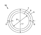
- a composite core shell material 100 including core 5 of lithium sulfide for storing energy and a first shell 10 composed of Li 4 P 2 S 7 that functions as a super ionic solid electrolyte that protects the core 5 from polysulfide shuttle.
- super ionic solid electrolyte it is meant that the Li 4 P 2 S 7 of the first shell 10 allows for the diffusion of lithium ions (Li + ) to and from the core 5 of the composite core shell material 100 .
- Carbon is typically added to the wet synthesis method to provide at least one second shell 15 that is composed of at least Li 4 P 2 S 7 and carbon (C).
- the lithium sulfide (Li 2 S) and diphosphorus pentasulfide (P 2 S 5 ) are mixed at a ratio of exactly 1:1.
- the lithium sulfide (Li 2 S) reacts with diphosphorus pentasulfide (P 2 S 5 ) to form a 1 to 1 stoichiometric complex that has a high solubility in acetonitrile.
- the acetonitrile dissolves at least 25 wt. % of the Li 2 S—P 2 S 5 complex.
- the acetonitrile dissolves from 10 wt. % of the Li 2 S—P 2 S 5 complex to 10 wt. % of the Li 2 S—P 2 S 5 complex.
- the mixing time for forming the first mixture may be reduced by increasing the mixing speed. In some embodiments, the mixing time for forming the first mixture may range from 0.5 minutes to 10 hours.
- the first mixture is formed at a temperature ranging from 20° C. to 25° C.
- the first mixture may further include additives for viscosity adjustments and pH adjustment.
- the timing for milling of the lithium sulfide (Li 2 S) and carbon (C) powder is typically dependent upon the original size of the raw material, the desired size for the milled product, and the milling mechanism.
- dry milling of the lithium sulfide (Li 2 S) and carbon (C) powder may include milling, e.g., dry ball milling, for a time period of 3 hours of less.
- dry milling of the lithium sulfide (Li 2 S) and carbon (C) powder may include milling, e.g., dry ball milling, for a time period of ranging from 1 hour to 3 hours.
- the second portion of lithium sulfide (Li 2 S) power and carbon (C) powder from the first mixture that includes a first component of the composite core shell material 100 that includes the first shell 10 of Li 4 P 2 S 7 encapsulating a core 5 of lithium sulfide (Li 2 S)
- possible damage to the first shell 10 of Li 4 P 2 S 7 by milling with carbon (C) can be eliminated.
- step 30 of the process flow depicted in FIG. 2 following the formation of the first shell 10 of Li 4 P 2 S 7 on the core 5 of lithium sulfide (Li 2 S), the first mixture that is formed at step 20 is mixed with the second mixture that is formed at step 25 .
- the addition of the second mixture of a second portion of lithium sulfide (Li 2 S) and carbon (C) powder to the first mixture that is formed at step 20 of the process flow depicted in FIG. 2 typically forms at least one second shell 15 composed of Li 4 P 2 S 7 and carbon (C) encapsulating the first shell 10 of Li 4 P 2 S 7 .
- the intimate contact of the second shell 15 composed of lithium sulfide (Li 2 S) and carbon (C) on the first shell 10 of Li 4 P 2 S 7 on the core 5 of lithium sulfide (Li 2 S) enables the conducting of electrons at the oxidation and reduction of the cathode materials during the operation of batteries.
- the mixing of the first mixture that is formed in step 20 with the second mixture that is formed in step 25 includes at least one of the mechanisms of convection, shear and diffusion to provide a homogenous mixture.
- Any mixer is suitable for mixing the second mixture including the second portion of lithium sulfide (Li 2 S) and carbon (C) powder with the solution of lithium sulfide (Li 2 S) and diphosphorus pentasulfide (P 2 S 5 ) in the organic solvent that comprises carbon (C) and hydrogen (H), e.g., acetonitrile, provided by the first mixture, so long as the mixer dissolves the second mixture within the solution of the first mixture.
- the mixer may include an impeller mixer, paddle type mixer, planetary mixer, flat blade turbine mixers, anchor mixer, wet ball mill and a combination or variation thereof.
- the mixing time for step 30 of the process flow depicted in FIG. 2 is selected to allow for the second mixture including the second portion of lithium sulfide (Li 2 S) and carbon (C) powder to dissolve in the organic solvent, e.g., acetonitrile, of the first mixture, which includes the first shell 10 of Li 4 P 2 S 7 on the core 5 of lithium sulfide (Li 2 S).
- the mixing time for combining the first mixture and the second mixture may be reduced by increasing the mixing speed.
- the mixing time for mixing the first mixture that was produced in step 20 with the second mixture that was produced in step 25 may range from 0.5 minutes to 10 hours.
- the solution of lithium sulfide (Li 2 S) and diphosphorus pentasulfide (P 2 S 5 ) in the organic solvent that comprises carbon and hydrogen, e.g., acetylene, provided by the first mixture is mixed with the second mixture of lithium sulfide (Li 2 S) and carbon (C) powder using a wet ball mill for a time period of about 2 hours.
- the first mixture and the second mixture may be combined at a temperature ranging from 20° C. to 25° C.
- Combining the first mixture and the second mixture at step 30 of the process flow depicted in FIG. 2 may further include additives for viscosity adjustments.
- the composition of the at least one second shell 15 includes 5% to 70% carbon with a remainder of Li 4 P 2 S 7 . In one embodiment, the composition of the at least one second shell 15 includes 50% Li 4 P 2 S 7 and 50% carbon (C).
- the carbon (C) content of the at least one second shell 15 of the composite core shell material 100 provides the electrical conductivity performance of the composite core shell material 100 . Therefore, in some embodiments, the carbon content of the composite core shell material 100 may be increased or decreased depending upon the intended application of the composite core shell material.
- Step 30 of the process flow depicted in FIG. 2 provides at least one second shell composed of Li 4 P 2 S 7 and carbon (C) powder.
- the third mixture is dried to remove the organic solvent and to provide a powder of composite core shell material 100 .
- the organic solvent e.g., acetonitrile
- the organic solvent e.g., acetonitrile
- heating the third mixture accelerates the removal of the organic solvent, e.g., acetonitrile.
- Any heat source may be employed to dry the third mixture.
- the heat source may me a furnace or heat lamps.
- the third mixture is heated to a temperature that ranges from 60° C. to 200° C. In another embodiment, the mixture is heated to a temperature that ranges from 120° C. to 160° C.
- the composite core shell material 100 includes lithium sulfide (Li 2 S) core 5 having a longest axis ranging from 1 micron to 100 microns, and a first shell 10 comprised of Li 4 P 2 S 7 in direct contact with an exterior surface of the lithium sulfide (Li 2 S) core 5 .
- the first shell 10 encapsulates the lithium sulfide (Li 2 S) core 5 .
- encapsulates it is meant that the core 5 of lithium sulfide (Li 2 S) is confined within the first shell 10 of Li 4 P 2 S 7 .
- the lithium sulfide (Li 2 S) core 5 may be composed entirely, i.e., 100%, of lithium sulfide (Li 2 S).
- the core 5 may be composed of lithium sulfide (Li 2 S) and incidental impurities.
- incident impurities refers to elements that are not purposeful additions to the core 5 , but that due to impurities and/or leaching from contact with manufacturing equipment, trace quantities of such elements being no greater than 0.05 wt % individually, and not grater than 1% when measured in combination, may find their way into the final core composition.
- the core 5 of the composite core shell material 100 may have a spherical geometry, in which the longest axis of the core is a diameter D1, which is equal to 1 micron to 100 microns. In another embodiment, the diameter D1 of the composite core shell material 11 ranges from 25 microns to 75 microns. In yet another embodiment, the diameter D1 of the composite core shell material 11 ranges from 35 microns to 55 microns.
- the geometry of the core 5 of the core shell material 100 is depicted as being spherical, it is not intended that the core 5 of lithium sulfide (Li 2 S) be limited to only this geometry, as other geometries for the core 5 are within the scope of the present disclosure.
- the core 5 may have a geometry that is oblong, cylindrical or multi-sided.
- the first shell 10 that is comprised of Li 4 P 2 S 7 is typically substantially free of carbon (C).
- substantially free it is meant that the maximum carbon content within the first shell is no greater than 1%.
- the first shell 10 of Li 4 P 2 S 7 is entirely free of carbon, i.e., the carbon content within the first shell 10 is 0%.
- the first shell 10 of Li 4 P 2 S 7 may have a thickness T1 ranging from 1 nm to 100 nm.
- the first shell 10 of Li 4 P 2 S 7 has a thickness T1 that ranges from 25 nm to 75 nm.
- the first shell 10 of Li 4 P 2 S 7 has a thickness T1 that ranges from 35 nm to 55 nm.
- each of the second shells 15 that is composed of Li 4 P 2 S 7 and carbon (C) in direct contact with an exterior surface of the first shell 10 of Li 4 P 2 S 7 .
- each of the second shells 15 has a composition that includes 70% to 99% of Li 4 P 2 S 7 and 1% to 30% carbon (C).
- each of the second shells 15 has a composition that includes 80% to 95% of Li 4 P 2 S 7 and 5% to 20% carbon (C).
- at least one of the second shells 15 encapsulates the first shell of Li 4 P 2 S 7 .
- each of the at least one second shell has a thickness ranging from 1 nm to 100 nm.
- the thickness of the at least one second shell ranges from 25 nm to 75 nm. In yet another embodiment, the thickness of each of the at one second shell ranges from 35 nm to 55 nm.
- FIG. 1 depicts a composite core shell material 100 having one second shell 15 of lithium sulfide (Li 2 S) and carbon (C), it is noted that any number of second shells 15 may be present.
- the final composition of the composite core shell material may have as great as 60 wt % lithium sulfide (Li 2 S) or as great as 60 wt % carbon (C).
- the final composition of the composite core shell material 100 may include 50 wt % to 70 wt % lithium sulfide (Li 2 S), 10 wt % to 30 wt % Li 4 P 2 S 7 , and 10 wt % to 30 wt % carbon.
- the final composition of the composite core shell material 100 includes 30 wt % Li 4 P 2 S 7 , 10 wt % carbon (C) and 60 wt % Li 2 S.
- the geometry of the composite core shell material 100 is depicted as being spherical, it is not intended that the composite core shell material 100 be limited to only this geometry, as other geometries for the composite core shell material 100 are within the scope of the present disclosure.
- the composite core shell material 100 may have a geometry that is oblong, cylindrical or multi-sided.
- One application for the composite core shell material 100 that is depicted in FIG. 1 which can be produced by the process flow depicted in FIG. 2 , is for the positive electrode of a wet cell lithium sulfur (Li—S) battery that employs an ether based wet (liquid) electrolyte. Because the portion of the composite core shell material 100 that is provided by the first shell 10 of Li 4 P 2 S 7 on the core 5 of lithium sulfide (Li 2 S) is not an electrical conductor, the rate of the performance of a positive electrode composed of the composite core shell material 100 provided by the present disclosure may depend upon the particle size of the composite core shell material 100 .
- the composite core shell material 100 instead of reducing the size of the composite core shell material 100 into the nanometer range, it has been determined that excellent cycling performance may be provided by sizing the composite core shell material 100 within the micrometer range, e.g., having a size ranging from 0.01 ⁇ m to 5 ⁇ m, with nanometer domains of Li 2 S@Li 4 P 2 S 7 and carbon (C).
- nanometer domains it is meant that agglomerates of core-shell particles are sized in the range of 10 nm to 100 nm.
- the longest axis L1 of the composite core shell material 100 may range from 0.01 ⁇ m to 100 ⁇ m. In another embodiment, the longest axis L1 of the composite core shell material 100 may range from 10 ⁇ m to 50 ⁇ m.
- the composite core shell material 100 is mixed with a solvent to provide a coating composition.
- the solvent may be an organic solvent.
- organic solvents that are suitable for being mixed with the composite core shell material 100 to form the coating composition include acetonitrile, acetone, dichloromethane (DCM), tetrahydrofuran (THF), ethyl acetate, dimethylformamide (DMF), dimethyl sulfoxide (DMSO), dimethoxyethane (DME) and a combinations thereof.
- the composite core shell material 100 is mixed with the organic solvent in an amount ranging from 20 wt % to 80 wt %.
- the composite core shell material 100 is mixed with the organic solvent in an amount ranging from 30 wt % to 70 wt %. It is noted that the above mixtures of composite core shell material 100 and organic solvent are provided for illustrative purposes only, the amount of composite core shell material 100 that is present in the mixture may be increased or decreased depending upon the amount of solid based electrolyte that is desired on the positive electrode of the battery. Further, the amount of composite core shell material 100 may also depend on the solubility of the composite core shell material 100 in the organic solvent.
- the composite core shell material 100 and the organic solvent may be mixed using any mechanical mixing apparatus, including but not limited to, an impeller mixer, a paddle type mixer, a planetary mixer, flat blade turbine mixers, an anchor mixer, a wet ball mill and a combination or variation thereof.
- the mixing time for forming the coating composition is selected so that the composite core shell material 100 is dissolved within the organic solvent.
- the coating composition may be applied to the conductive substrate using a deposition process, such as spray deposition, brushing, curtain flow coating, dipping and derivatives and combinations thereof. Following deposition, the coating composition may then be dried to provide the positive electrode for a lithium sulfur (Li—S) wet battery cell.
- the final composition of the coating for the positive electrode includes 60 lithium sulfide (Li 2 S):20Li 4 P 2 S 7 :20 carbon (C).
- FIG. 3 depicts one embodiment of a lithium sulfur (Li—S) wet cell battery 40 including a positive electrode 45 that includes the coating of the composite core shell material 100 .
- the carbon (C) within the at least one second shell 15 of the composite core shell material 100 that provides the positive electrode 45 conducts electrons and lithium ions (Li + ), and the first shell 10 of Li 4 P 2 S 7 of the composite core shell material 100 that provides the positive electrode 45 conducts lithium ions (Li + ).
- the first shell 10 of the Li 4 P 2 S 7 is a barrier to diffusion of polysulfides to the core 5 of the composite core shell material 100 that is comprised of the lithium sulfide (Li 2 S).
- FIG. 4 depicts a charge/discharge profile of a lithium sulfur (Li—S) wet cell battery 40 including a positive electrode 45 having a coating of the composite core shell material 100 , which includes a Li 2 S core, a first shell composed of Li 4 P 2 S 7 and a second shell of Li 4 P 2 S 7 and carbon (C).
- Plot 65 in FIG. 4 is the charge profile
- plot 70 in FIG. 4 is the discharge profile.
- the charge and discharge profiles depicted in FIG. 4 are consistent with the performance of lithium sulfur (Li—S) batteries.
- the coating of the composite core shell material 100 which provides the positive electrode 45 of the lithium sulfur (Li—S) wet cell battery 40 , typically has an excellent retention of capacity in repetitive cycling.
- the first shell 10 of Li 4 P 2 S 7 which provides a solid electrolyte for the lithium sulfur (Li—S) wet cell battery 40 , efficiently prevents the dissolution of sulfur (S), e.g., lithium sulfide (Li 2 S).
- S sulfur
- Li 2 S lithium sulfide
- step 86 of the process flow depicted in FIG. 6 is optional.
- the precipitate of Li 3 PS 4 may be allowed to precipitate from the liquid solvent by sedimentation without applying an additional force.
- the sedimentation of the precipitated Li 3 PS 4 may then be screened from the liquid solvent.
- the first temperature for the first phase change to an amorphous phase of the precipitate of Li 3 PS 4 may be a temperature ranging from 90° C. to 110° C. In another example, the first temperature for the first phase change to an amorphous phase of the precipitate of Li 3 PS 4 may be a temperature ranging from 95° C. to 105° C. In one example, the first temperature for the first phase change to an amorphous phase of the precipitate of Li 3 PS 4 may at 100° C.
- the recrystallized ⁇ -Li 3 PS 4 may range from 1.8 ⁇ 10 ⁇ 3 Scm ⁇ 1 to 1.5 ⁇ 10 ⁇ 4 Scm ⁇ 1 .
- the recrystallized ⁇ -Li 3 PS 4 formed using the wet chemical process that is described above with reference to FIG. 6 is stable at room temperature, e.g., 20° C. to 25° C.
- stable at room temperature it is meant that the recrystallized ⁇ -Li 3 PS 4 does not experience a phase change to ⁇ -Li 3 PS 4 at temperatures below 227° C., such as room temperature, e.g., 20° C.
- the lithium ionic conduction along this interfacial region is dominant in overall conduction in nanocrystalline samples, resulting in different activation energy.
- the nanoporous structure with micro strain creates a large number of lattice defects and a charge imbalance at the interfaces/grain boundaries, thus enhancing the ionic conductivity of the recrystallized ⁇ -Li 3 PS 4 significantly when compared to ⁇ -Li 3 PS 4 that is not formed using the wet chemical synthesis method described with reference to FIG. 6 .
- a solid state battery 200 that includes a negative electrode 97 comprised of lithium (Li), a positive electrode 99 comprised of platinum, and a solid electrolyte 98 of ⁇ -Li 3 PS 4 , as depicted in FIG. 7 .
- a solid-state battery 200 is a battery that has both solid electrodes and solid electrolytes.
- the solid electrolyte 98 of ⁇ -Li 3 PS 4 may have a crystallite size of 250 nm or less, wherein the ⁇ -Li 3 PS 4 is a micro-strained and a porous structure.
- the ratio of lithium sulfide (Li 2 S) to diphosphorus pentasulfide (P 2 S 5 ) for forming the first mixture at step 101 ranges from 2.75:1 to 3.25:1.
- the ratio of lithium sulfide (Li 2 S) to diphosphorus pentasulfide (P 2 S 5 ) for forming the first mixture at step 101 of the process flow depicted in FIG. 8 is selected for forming a first shell of Li 3 PS 4 on a core of lithium sulfide (Li 2 S).
- the ratio of lithium sulfide (Li 2 S) to diphosphorus pentasulfide (P 2 S 5 ) for forming the first mixture at step 101 of the process flow depicted in FIG. 8 is 3:1.
- the solvent may then removed.
- removing the solvent from the Li 3 PS 4 may produce at least one phase change to a recrystallized ⁇ -Li 3 PS 4 .
- Removal of the liquid containing solvent of carbon (C) and hydrogen (H), e.g., tetrahydrofuran (THF) may include a heat treatment that effectuates the phase change in the as synthesized Li 3 PS 4 to the beta phase of Li 3 PS 4 , i.e., ⁇ -Li 3 PS 4 .
- the dimensions and the geometry of the composite core shell material including at least one shell composed of ⁇ -Li 3 PS 4 that are provided by the process flow depicted in FIG. 8 are similar dimensions and geometries of the composite core shell material including at least one shell of Li 4 P 2 S 7 , which are described above with reference to FIGS. 1 and 3 .
- the composite core shell material produced by the process flow depicted in FIG. 8 includes a lithium sulfide (Li 2 S) core having a longest axis ranging from 0.01 micron to 100 microns.
- a first shell of the composite core shell material that is comprised of ⁇ -Li 3 PS 4 is in direct contact with an exterior surface of the lithium sulfide core (Li 2 S) and encapsulates the lithium sulfide core (Li 2 S).
- the first shell may have a thickness ranging from 1 nm to 100 nm.
- At least one second shell comprised of ⁇ -Li 3 PS 4 and carbon (C) is present in direct contact with an exterior surface of the first shell.
- Each of at least one second shell may have a thickness that ranges from 1 nm to 100 nm.
- the composite core shell material produced by the process flow depicted in FIG. 8 may include 50 wt % to 70 wt % lithium sulfide (Li 2 S), 10 wt % to 30 wt % ⁇ -Li 3 PS 4 , and 10 wt % to 30 wt % carbon.
- the composite core shell material including the ⁇ -Li 3 PS 4 shell composition has an ionic conductivity at room temperature, e.g., 20° C. to 25° C., ranging from 1.0 ⁇ 10 ⁇ 6 S/cm to 1.0 ⁇ 10 ⁇ 3 S/cm.
- the ionic conductivity for the composite core shell material including the ⁇ -Li 3 PS 4 shell composition may be suitable for battery components.
- a wet cell battery in one embodiment, includes a positive electrode including a composite core shell material, in which at least one shell has a composition that includes ⁇ -Li 3 PS 4 .
- the wet cell battery including the positive electrode of the composite core shell material having the ⁇ -Li 3 PS 4 shell composition is similar to the wet cell battery that is depicted in FIG. 3 . Details for forming a positive electrode using a composite core shell material are described above with reference to FIG. 3 .
- the mixture of solvent and the composite core shell material may be applied to a conductive substrate using a deposition method, such as spraying or brushing.
- a deposition method such as spraying or brushing.
- the description of the negative electrode 50 and the liquid electrolyte 55 that is depicted in FIG. 3 is suitable for the negative electrode and liquid electrolyte for the wet cell battery including the positive electrode of the composite core shell material having the ⁇ -Li 3 PS 4 shell composition.
- a first portion of the as-synthesized precipitation was retained for characterization (hereafter referred to as “as-synthesized precipitation of Li 3 PS 4 ”), and a second portion of the as-synthesized precipitation was heated to provide at least one phase change to a recrystallized ⁇ -Li 3 PS 4 (hereafter referred to as “recrystallized ⁇ -Li 3 PS 4 ”). More specifically, to provide the recrystallized ⁇ -Li 3 PS 4 , the as-synthesized precipitation was subject to elevated temperatures at 100° C., 120° C. and 140° C. under vacuum to remove the tetrahydrofuran (THF).
- THF tetrahydrofuran
- Test samples for characterization of the ionic conductivity for the recrystallized ⁇ -Li 3 PS 4 were formed into pellets (hereafter referred to as “recrystallized ⁇ -Li 3 PS 4 pellets”) having a diameter of approximately 12.5 mm and a thickness of approximately 1 mm.
- the recrystallized ⁇ -Li 3 PS 4 pellets were prepared by pressing the powder with carbon-coated aluminum foil on both sides in argon-filled glove box. The pellet was sealed in a cell using stainless steel disks as blocking electrodes.
- A.C. impedance measurements were conducted in the frequency range of 10 MHz to 1 Hz with the amplitude of 100 mV by using impedance analyzer (Solartron 1260). The temperature was controlled between ⁇ 10° C. to 90° C. in a temperature chamber (Maccor, ⁇ 0.5° C.).
- FIG. 11 is an enlarged image from section “A” of the ⁇ -Li 3 PS 4 that is depicted in FIG. 10 .
- the enlarged image from section “A” of the ⁇ -Li 3 PS 4 that is depicted in FIG. 11 exhibits nanoporous structure derived after the removal of solvent, i.e., tetrahydrofuran (THF).
- solvent i.e., tetrahydrofuran
- the samples i.e., the as-synthesized precipitate and the recrystallized ⁇ -Li 3 PS 4 , were characterized by X-ray diffraction (PANalytical Powder Diffractometer) and Raman spectroscopy (Princeton Instruments Acton Trivista 555).
- the inductively coupled plasma determined the Li/P ratio.
- Inductively coupled plasma spectroscopy determines the Li/P ratio, which is close to the stoichiometric Li/P ratio of 3:1 in Li 3 PS 4 .
- FIG. 12 is a plot of Raman spectroscopy for recrystallized ⁇ -Li 3 PS 4 , as indicated by plot 90 , and as synthesized samples of Li 3 PS 4 , as indicated by plot 89 .
- FIG. 13 depicts X-ray diffraction (XRD) patterns for recrystallized ⁇ -Li 3 PS 4 , as indicated by plot 92 , and as synthesized samples of Li 3 PS 4 , as indicated by plot 91 .
- Raman spectroscopy shows the characteristic peak of Li 3 PS 4 at 422 cm ⁇ 1 for the as-synthesized samples, which is in good agreement with that for pure Li 3 PS 4 , as depicted in plot 89 of FIG. 13 .
- the additional peaks at low wavelengths indicate the strong coordination of tetrahydrofuran (THF) with Li 3 PS 4 , which shows very different diffraction pattern, as depicted in plot 91 of FIG. 13 .
- the as-synthesized powders were well crystallized with a strong diffraction peak at about 8.4° (2 ⁇ ) and other diffraction peaks with significantly lower intensity, as illustrated by plot 91 of FIG. 13 .
- the Raman spectroscopy agrees well with that for single crystal Li 3 PS 4 , as illustrated by plot 89 in FIG. 12 .
- X-ray diffraction data for the heat treated as-synthesized powders illustrated a significant decrease in intensity with the increase of the temperature for the heat treatment, which was accompanied with a significant weight loss due to the removal of tetrahydrofuran (THF) solvated with Li 3 PS 4 .
- THF tetrahydrofuran
- the as-synthesized crystal phase transfers to amorphous phase. Recrystallization of the amorphous phase occurs at above 120° C. Referring to plot 92 of FIG.
- the X-ray diffraction pattern for the recrystallized i.e., heat treated as synthesized Li 3 PS 4
- can be indexed to ⁇ -Li 3 PS 4 which has an orthorhombic crystal structure having space group pnma.
- FIG. 14 illustrates a Rietveld refinement of x-ray diffraction of recrystallized ⁇ -Li 3 PS 4 .
- FIG. 15 is a Williamson Hall plot (B cos ⁇ vs sin ⁇ ) that is derived from Rietveld refinement depicted in FIG. 14 .
- the linear dependence of B cos ⁇ on sin ⁇ in the Williamson Hall plot confirm the existence of micro strain.
- Size and strain analysis gives the grain size of 92 nm, which is larger than that ( ⁇ 73 nm) obtained from size-only analysis.
- the size and strain data for the recrystallized ⁇ -Li 3 PS 4 provided using the Rietveld refinement was consistent with the grain size determined from the scanning electron microscopy (SEM) images for the recrystallized ⁇ -Li 3 PS 4 depicted in FIG. 10 , in which the recrystallized ⁇ -Li 3 PS 4 exhibited a grain size of about 100 nm.
- FIGS. 16 and 17 illustrate Brunauer-Emmett-Teller (BET) characterization of recrystallized ⁇ -Li 3 PS 4 .
- Plot 93 in FIG. 16 is a plot of N 2 desorption isotherms at a temperature of 77° K
- plot 94 is a plot of N 2 adsorption isotherms at a temperature of 77° K.
- N 2 adsorption/desorption isotherms were measure using a Micromeritic Gemini 275 system.
- the specific surface areas was calculated using the Brunauer-Emmett-Teller (BET) theory based on the adsorption branches of the isotherms.
- the high surface area of 15.6 m 2 g ⁇ 1 indicates the nanoporous structure of recrystallized ⁇ -Li 3 PS 4 .
- FIG. 17 is a plot of the pore size distribution that was calculated by using adsorption isotherm.
- the pore size distributions were calculated by using Barrett-Joyner-Halenda (BJH) method based on the adsorption branches of the isotherms.
- BJH Barrett-Joyner-Halenda
- the average pore size of 28 nm depicted in FIG. 17 was consistent with that 33 nm measurement that was obtained from small angle X-ray diffraction measurement.
- the as-synthesized precipitate of Li 3 PS 4 did not show any detectable surface area, while the heat-treated recrystallized ⁇ -Li 3 PS 4 samples provide a high BET surface area of 15.6 m 2 g ⁇ 1 , as depicted in FIG. 16 .
- the high surface area indicated that the recrystallized ⁇ -Li 3 PS 4 had a porous structure with the average pore size of 28 nm.
- the porous structure and micro-strain created by solvent removal, e.g., removal of tetrahydrofuran (THF), generates a large number of lattice defects, which can cause a charge imbalance.
- the increased surface energy may induce chemical lattice distortion, which in turn lowers the phase transition temperature.
- the stabilization of ⁇ -Li 3 PS 4 at room temperature can be attributed to the increased surface energy and the resulted charge imbalance.
- FIG. 18 is a plot of small angle x-ray scattering data that was collected using an Anton-Paar SAXSess instrument with Cu K ⁇ radiation in line mode.
- the sample of recrystallized ⁇ -Li 3 PS 4 was placed into a past cell and data was collected with a CDD operating in 1-dimensional mode. The data was treated with background subtraction, dark current substrate, desmearing and Guinier analysis.
- the plot identified by reference number 21 is the experimental data.
- the plot identified by reference number 22 is the Guinier fitting.
- the small angle x-ray scattering data indicated that the pore size was of the recrystallized ⁇ -Li 3 PS 4 sample was approximately 33 nm.
- FIGS. 19-21 illustrate the lithium ionic conductivity of recrystallized ⁇ -Li 3 PS 4 pellets that are formed in accordance with the procedures described above in the section of this paper titled “preparation of test samples”.
- FIG. 19 is temperature dependent Arrhenius plot.
- FIGS. 20 and 21 depict the impedance spectrum for Li 3 PS 4 measured from recrystallized ⁇ -Li 3 PS 4 pellets. The total conductivity is determined by using the intersection between the semiarc and straight line as the total resistance. The continuous linear relationship between the conductivity (log) and the reciprocal of absolute temperature (1/T) indicates that no phase transition occurs between ⁇ 10° C. and 90° C. Plot 95 of FIG.
- FIG. 22 is a cyclic voltammogram that was measured from a Li/Li 3 PS 4 /Pt cell at a scan rate of 100 mVs ⁇ 1 between ⁇ 0.2 V and 5 V at room temperature (20° C. to 25° C.) by using a potentiostat (EG&G).
- the lithium (Li) and platinum (Pt) serve as reference and working electrodes, respectively.
- the Li/Li 3 PS 4 /Li symmetric cell was tested on Maccor battery testing station with the current of 0.1 mAcm ⁇ 2 at room temperature (20° C. to 25° C.) and with the current of 0.5 mAcm ⁇ 2 at 80° C.
Abstract
Method of forming lithium-containing electrolytes are provided using wet chemical synthesis. In some examples, the lithium containing electrolytes are composed of β-Li3PS4 or Li4P2S7. The solid electrolyte may be a core shell material. In one embodiment, the core shell material includes a core of lithium sulfide (Li2S), a first shell of β-Li3PS4 or Li4P2S7, and a second shell including one of β-Li3PS4 or Li4P2S7 and carbon. The lithium containing electrolytes may be incorporated into wet cell batteries or solid state batteries.
Description
This application is a divisional of U.S. application Ser. No. 13/463,451 filed on May 3, 2012, the contents of which are incorporated herein by reference in their entirety.
This invention was made with government support under Contract Number DE-AC05-00OR22725 between the United States Department of Energy and UT-Battelle, LLC. The U.S. government has certain rights in this invention.
The present disclosure relates to materials for battery applications, such as solid state batteries and batteries including liquid electrolytes.
Lithium-ion batteries have found widespread usage as electrical energy storage devices in various portable electronics because of their light weight relative to other types of batteries. However, for high power applications such as electric vehicles, there has been a continuing effort to improve the energy output and useful lifetime in lithium ion batteries to better suit these high power applications. Lithium-sulfur (Li/S) batteries, in particular, hold great promise for high power applications. Lithium-sulfur batteries have a theoretical capacity of 1675 mAhg−1, nearly one magnitude higher than that of LiFePO4 (theoretical capacity of 176 mAhg−1). Nevertheless, the Li/S system has not yet been implemented in high power applications, because of two significant obstacles, the poor electrical conductivity of elemental sulfur and the intrinsic polysulfide shuttle.
In one aspect, the present disclosure provides a method of forming a composite core shell material including lithium (Li). In one embodiment, the method of forming the composite core shell material includes forming a first mixture including a solid component of a first portion of lithium sulfide (Li2S) and diphosphorus pentasulfide (P2S5) in a ratio ranging from 0.75:1 to 1.25:1 with a liquid solvent comprising carbon and hydrogen to form a first shell on a core material of the composite core shell material. The core of the composite core shell material may be comprised of lithium sulfide (Li2S) and the first shell of the composite core shell material may be comprised of Li4P2S7. A second mixture of a second portion of lithium sulfide (Li2S) and a carbon (C) powder may then be formed. The second mixture may be combined with the first mixture after the first shell of the composite core shell material is formed. Combining the first mixture with the second mixture provides at least one second shell that is comprised of Li4P2S7 and carbon (C), wherein the at least one second shell is in contact with the first shell. The liquid solvent may then be removed.
In another aspect, a composite core shell material is provided that in one embodiment includes a lithium sulfide core having a longest axis ranging from 1 micron to 100 microns, and a first shell comprised of Li4P2S7. The first shell is in direct contact with an exterior surface of the lithium sulfide core and encapsulates the lithium sulfide core. The first shell may have a thickness that ranges from 1 nm to 100 nm. The composite core shell material may also include at least one second shell comprised of lithium sulfide and carbon. The second shell of the composite core shell material may be in direct contact with an exterior surface of the first. The at least one second shell may have a thickness ranging from 1 nm to 100 nm.
In yet another aspect, the present disclosure provides a wet cell battery. In one embodiment, the wet cell battery may include a negative electrode of lithium (Li), an ether based electrolyte, and a positive electrode comprising a conductive substrate coated with a composite core shell material. The composite core shell material may include a lithium sulfide core, a first shell comprised of Li4P2S7 in direct contact with an exterior surface of the lithium sulfide core and encapsulating the lithium sulfide core, and at least one second shell comprised of Li4P2S7 and carbon (C) in direct contact with an exterior surface of the first shell.
In a further aspect, the present disclosure provides a method of reducing polysulfide shuttle in a lithium sulfur (Li—S) battery. In one embodiment, the method may include positioning a negative electrode comprised of lithium (Li) within a wet cell of an ether based electrolyte. A positive electrode may then be formed comprising a coating of a composite core shell material. The core of the composite core shell material may be composed of lithium sulfide (Li2S), and the shell of the composite core shell material is a solid electrolyte. The solid electrolyte may include a diffusion barrier layer to polysulfides that is comprised of Li4P2S7, which encapsulates the core of lithium sulfide (Li2S). The solid electrolyte may further include a conductive layer that is comprised of at least Li4P2S7 and carbon (C). The conductive layer of the solid electrolyte is present on the diffusion barrier layer. The positive electrode may be positioned in the wet cell and is separated from the negative electrode.
In another aspect of the present disclosure, a method of forming a solid electrolyte material is provided. In one embodiment, the method of forming the solid electrolyte material may include mixing lithium sulfide (Li2S) and diphosphorus pentasulfide (P2S5) in a ratio ranging from 2.75:1 to 3.25:1 with a liquid solvent comprising tetrahydrofuran (THF) to form a precipitate of Li3PS4. The precipitate of Li3PS4 may then be heated to provide at least one phase change to a recrystallized β-Li3PS4. The recrystallized β-Li3PS4 has a crystallite size of 500 nm or less.
In yet another aspect, a solid electrolyte material is provided that in one embodiment includes β-Li3PS4 having a crystallite size of 100 nm or less. The β-Li3PS4 may be a micro-strained structure characterized by a lattice strain ranging from 0.01% to 10%. The β-Li3PS4 may further be a porous structure that is characterized by a surface area that ranges from 10 m2g−1 to 20 m2g−1. The β-Li3PS4 may have an ionic conductivity ranging from 1.5×10⁻⁴ Scm−1 to 3.5×10⁻⁴ Scm−1.
In a further aspect of the present disclosure, a solid state battery is provided that includes a negative electrode comprised of lithium, a positive electrode comprised of platinum, and a solid electrolyte of β-Li3PS4. The solid electrolyte of β-Li3PS4 may have a particle size of 100 nm or less, wherein the β-Li3PS4 is a micro-strained and a porous structure. The micro-strained structure may be characterized by a lattice strain ranging from 0.01% to 10%. The porous structure may be characterized by a surface area that ranges from 10 m2g−1 to 20 m2g−1. In one embodiment, the β-Li3PS4 that provides the solid electrolyte of the solid state battery has an ionic conductivity ranging from 1.5×10⁻⁴ Scm−1 to 3.5×10⁻⁴ Scm−1.
In another aspect, a method of forming a composite core shell material is provided that includes shells composed of β-Li3PS4. The method may include providing a first mixture including a solid component of a first portion of lithium sulfide (Li2S) and diphosphorus pentasulfide (P2S5) in a ratio ranging from 2.75:1 to 3.25:1 with a liquid solvent comprising carbon and hydrogen to form a first shell of the composite core shell material. The core of the composite core shell material is comprised of lithium sulfide (Li2S) and the first shell of the composite core shell material is comprised of Li3PS4. A second mixture is formed of a second portion of lithium sulfide and carbon powder. The second mixture is combined with the first mixture after the first shell of the composite core shell material is formed. The combining of the first mixture with the second mixture provides at least one second shell that is comprised of Li3PS4 and carbon (C), wherein the at least one second shell is in contact with the first shell. The solvent is then removed. Removing the solvent from the Li3PS4 may produce at least one phase change to a recrystallized β-Li3PS4.
In yet another aspect, a composite core shell material is provided having at least one shell with a composition that includes β-Li3PS4. In one embodiment, the composite core shell material includes a lithium sulfide (Li2S) core having a longest axis ranging from 0.01 micron to 100 microns. A first shell of the composite core shell material that is comprised of β-Li3PS4 is in direct contact with an exterior surface of the lithium sulfide core (Li2S) and encapsulates the lithium sulfide core (Li2S). The first shell may have a thickness ranging from 1 nm to 100 nm. At least one second shell comprised of β-Li3PS4 and carbon (C) is present in direct contact with an exterior surface of the first shell. Each of at least one second shell may have a thickness that ranges from 1 nm to 100 nm.
In a further aspect, a wet cell battery is provided that includes a positive electrode including a composite core shell material, in which at least one shell has a composition that includes β-Li3PS4. In one embodiment, the wet cell battery includes an ether based electrolyte, a negative electrode present in the ether based electrolyte, and a positive electrode present in the ether based electrolyte separated from the negative electrode. The positive electrode may include a conductive substrate coated with a composite core shell material. The composite core shell material includes a lithium sulfide core, a first shell comprised of β-Li3PS4 in direct contact with an exterior surface of the lithium sulfide core and encapsulating the lithium sulfide core, and at least one second shell comprised of Li3PS4 and carbon (C) in direct contact with an exterior surface of the first shell.
The following detailed description, given by way of example and not intended to limit the disclosure solely thereto, will best be appreciated in conjunction with the accompanying drawings, wherein like reference numerals denote like elements and parts, in which:
Detailed embodiments of the present disclosure are described herein; however, it is to be understood that the disclosed embodiments are merely illustrative of the compositions, structures and methods of the disclosure that may be embodied in various forms. In addition, each of the examples given in connection with the various embodiments are intended to be illustrative, and not restrictive. Further, the figures are not necessarily to scale, some features may be exaggerated to show details of particular components. Therefore, specific structural and functional details disclosed herein are not to be interpreted as limiting, but merely as a representative basis for teaching one skilled in the art to variously employ the compositions, structures and methods disclosed herein. References in the specification to “one embodiment”, “an embodiment”, “an example embodiment”, etc., indicate that the embodiment described may include a particular feature, structure, or characteristic, but every embodiment may not necessarily include the particular feature, structure, or characteristic. Moreover, such phrases are not necessarily referring to the same embodiment. Further, when a particular feature, structure, or characteristic is described in connection with an embodiment, it is submitted that it is within the knowledge of one skilled in the art to affect such feature, structure, or characteristic in connection with other embodiments whether or not explicitly described.
In some embodiments, the composite core shell material 100 disclosed herein is suitable for a solid electrolyte that may be employed as a coating on the electrode of a wet cell battery, such as a lithium-sulfide battery (LiS). Lithium-ion battery (sometimes Li-ion battery or LIB) is a family of rechargeable battery types in which lithium ions move from the negative electrode to the positive electrode during discharge, and back when charging. Lithium-sulfur (Li—S) batteries can suffer from poor ionic and electronic conductivity for the sulfur containing components of the battery, e.g., sulfur containing electrodes, and their discharging byproducts. For example, the electrical conductivity of elemental sulfur is as low as 5×10⁻³⁰ S/cm at 25° C. Such a low conductivity causes poor electrochemical contact to the sulfur containing components of the battery and leads to low utilization of active materials in the positive electrode, e.g., cathode.
To compensate for the poor ionic and electronic conductivity for the sulfur containing electrodes, a liquid electrolyte is conventionally employed, which has a high solubility of lithium polysulfides and sulfide. The utilization of sulfur in batteries containing liquid electrolyte depends on the solubility of these sulfur species in the liquid electrolyte. Further, the sulfur in the positive electrode, e.g., cathode, except at the full charge state, is generally present as a solution of polysulfides in the electrolyte. The concentration of polysulfide species Sn 2− with n greater than 4 at the positive electrode is generally higher than that at the negative electrode, e.g., anode, and the concentration of Sn 2− with n smaller than 4 is generally higher at the negative electrode than the positive electrode. The concentration gradients of the polysulfide species drive the intrinsic polysulfide shuttle between the electrodes. Polysulfide shuttle transports sulfur species back and forth between the two electrodes, in which the sulfur species may be migrating within the battery all the time. Polysulfide shuttle leads to poor cyclability, high current leakage, and low charge-discharge efficiency. Further, a portion of the polysulfide is transformed into lithium sulfide (Li2S), which is deposited on the negative electrode. The deposited polysulfide may cause a “chemical short” of the battery. The “chemical short” leads to the loss of active materials, corrosion of the lithium containing negative electrode, i.e., anode, and a low columbic efficiency. Further, the mobile sulfur species causes the redistribution of sulfur in the battery and imposes a poor cycle-life for the battery, in which the poor cycle life directly relates to micro-structural changes of the electrodes. This deposition process occurs in each charge/discharge cycle, and eventually leads to the complete loss of capacity of the sulfur positive electrode. The deposition of lithium sulfide also leads to an increase of internal cell resistance within the battery due to the insulating nature of lithium sulfide. Progressive increases in charging voltage and decreases in discharge voltage are common phenomena in lithium-sulfur (Li—S) batteries, because of the increase of cell resistance in consecutive cycles. Hence, the energy efficiency decreases with the increase of cycle number.
In some embodiments, the composite core shell material 100 that is provided herein increases the ionic conductivity of the sulfur-containing positive electrode of wet cell lithium sulfur (Li—S) batteries by employing a lithium sulfide (Li2S) and diphosphorus pentasulfide (P2S5) based solid electrolyte. Referring to FIGS. 1 and 2 , in one embodiment a wet synthesis method has been provided in which lithium sulfide (Li2S) and diphosphorus pentasulfide (P2S5) are mixed in an organic solvent at room temperature, e.g., between 20° C. and 25° C., to form a composite core shell material 100 including core 5 of lithium sulfide for storing energy and a first shell 10 composed of Li4P2S7 that functions as a super ionic solid electrolyte that protects the core 5 from polysulfide shuttle. By “super ionic solid electrolyte” it is meant that the Li4P2S7 of the first shell 10 allows for the diffusion of lithium ions (Li+) to and from the core 5 of the composite core shell material 100. Carbon is typically added to the wet synthesis method to provide at least one second shell 15 that is composed of at least Li4P2S7 and carbon (C). The carbon increases the electronic conductivity of the composite core shell material 100 in comparison to a shell material of Li4P2S7 that does not include carbon (C). The details of at least one embodiment of a method of forming a composite core shell material 100 including Li4P2S7 are now described in more detail with reference to FIG. 2 . It is noted that the process sequence illustrated in FIG. 2 is not limited to only the steps that of the depicted process flow, as other initial and final process steps may be employed. Further, intermediate process steps have also been contemplated.
In one embodiment, the process flow depicted in FIG. 2 may begin with forming a first mixture including a solid component of a first portion of lithium sulfide (Li2S) and diphosphorus pentasulfide (P2S5) in a ratio ranging from 0.75:1 to 1.25:1 with a liquid solvent comprising carbon and hydrogen at step 20. Lithium sulfide (Li2S) and diphosphorus pentasulfide (P2S5) are both solids and typically have a low solubility in solvents, e.g., organic solvents. Therefore, it can be difficult to achieve practical concentrations of lithium sulfide (Li2S) and diphosphorus pentasulfide (P2S5) within an organic solvent to form a coating solution. Surprisingly, in some embodiments, it has been determined that lithium sulfide (Li2S) and diphosphorus pentasulfide (P2S5) may be dissolved in an organic solvent of acetonitrile (CH3CN), when the lithium sulfide (Li2S) and diphosphorus pentasulfide (P2S5) are mixed at a ratio of about 1:1. In one example, the lithium sulfide (Li2S) and diphosphorus pentasulfide (P2S5) are mixed at a ratio of exactly 1:1. The lithium sulfide (Li2S) reacts with diphosphorus pentasulfide (P2S5) to form a 1 to 1 stoichiometric complex that has a high solubility in acetonitrile. In one example of a typical reaction, the acetonitrile dissolves at least 25 wt. % of the Li2S—P2S5 complex. In another example of a typical reaction, the acetonitrile dissolves from 10 wt. % of the Li2S—P2S5 complex to 10 wt. % of the Li2S—P2S5 complex.
During mixing of the lithium sulfide (Li2S) and diphosphorus pentasulfide (P2S5) with the organic solvent of acetonitrile (CH3CN) at step 20 of the process flow depicted in FIG. 2 , the 1 to 1 (hereafter referred to as “1:1”) ratio Li2S—P2S5 solution reacts with lithium sulfide (Li2S) to form Li4P2S7, which is a 2 to 1 (hereafter referred to as “2:1”) ratio product of Li2S—P2S5. Li4P2S7 is a super-ionic solid electrolyte that is insoluble in organic solvents. Referring to FIG. 1 , the 1:1 ratio Li2S—P2S5 solution enables the coating of a core 5 of lithium sulfide (Li2S) with a first shell 10 of Li4P2S7, in which the first shell 10 is a 2:1 ratio product of Li2S—P2S5. The first shell 10 of Li4P2S7 is the product of a surface reaction between Li2S and the Li2S—P2S5 solution. In one embodiment, the first shell 10 of the composite core shell material 100 imparts excellent ion conductivity to the core 5 of Li2S. By “ion conductivity” it is meant that ions, such as lithium (Li+) ions, can diffuse through the first shell 10 to the core 5 of the composite core shell material 100, and that ions, such as lithium (Li+) ions, from the core 5 can diffuse through the first shell 10 to the exterior of the core shell material 100.
Forming the first mixture may include dry milling of the lithium sulfide (Li2S) and diphosphorus pentasulfide (P2S5) followed by mechanical mixing with the solvent comprising carbon (C) and hydrogen (H), e.g., acetonitrile. The lithium sulfide (Li2S) powder may have an average particle size ranging from 0.5 to 20 microns. The diphosphorus pentasulfide (P2S5) may have an average particle size ranging from 0.5 to 20 microns. Although, the solvent comprising carbon and hydrogen has been described above as acetonitrile, it is not intended that the present disclosure is not limited to only acetonitrile. The carbon and hydrogen solvent may be any solvent that is suitable for dissolving lithium sulfide (Li2S) and diphosphorus pentasulfide (P2S5). For example, in addition to acetonitrile, other examples of the solvents that are suitable for the process sequence illustrated in FIG. 2 include, but are not limited to, at least one of acetone, dichloromethane (DCM), tetrahydrofuran (THF), ethyl acetate, dimethylformamide (DMF), dimethyl sulfoxide (DMSO), dimethoxyethane (DME) and a combinations thereof.
Milling is a process that in some embodiments employs compression and/or shear forces to reduce the average particles size of a solid material, such as a powder. Some apparatus that may be employed for milling of lithium sulfide (Li2S) and diphosphorus pentasulfide (P2S5) include ball mills, vibratory mills, attrition mills, fluid energy mills and roller mills. The milled lithium sulfide (Li2S) and/or diphosphorus pentasulfide (P2S5) may have an average particle size ranging from 0.01 μm to 5 μm. In another embodiment, the milled lithium sulfide (Li2S) and/or diphosphorus pentasulfide (P2S5) may have an average particle size ranging from 0.01 μm to 5 μm. The timing for milling of the lithium sulfide (Li2S) and diphosphorus pentasulfide (P2S5) is typically dependent upon the original size of the raw material, the desired size for the milled product, and the milling mechanism. For example, a ball mill is typically a hollow rotating cylinder that is least partially filled with wear resistant media having the shapes or rods, short cylinders, and/or balls, wherein the tumbled media provides a grinding action by impacting and shearing the particles of lithium sulfide (Li2S) and diphosphorus pentasulfide (P2S5) on their surfaces. The ball mill media is only one factor that impacts the milling time for providing a desired size for the milled produced, e.g., milled lithium sulfide (Li2S) and/or diphosphorus pentasulfide (P2S5). In one example, dry milling of the lithium sulfide (Li2S) and/or diphosphorus pentasulfide (P2S5) may include milling, e.g., dry ball milling, for a time period of 3 hours of less. In another example, dry milling of the lithium sulfide (Li2S) and/or diphosphorus pentasulfide (P2S5) may include milling, e.g., dry ball milling, for a time period of ranging from 1 hour to 3 hours. In yet another example, the dry milling of the lithium sulfide (Li2S) and/or diphosphorus pentasulfide (P2S5) may include milling, e.g., dry ball milling, for a time period of 2 hours. In one embodiment, the lithium sulfide (Li2S) powder and diphosphorus pentasulfide (P2S5) powder are dry milled together to provide a homogeneous mixture of lithium sulfide (Li2S) and diphosphorus pentasulfide (P2S5). Milling of the lithium sulfide (Li2S) and/or diphosphorus pentasulfide (P2S5) may be at a temperature ranging from 20° C. to 25° C.
Following dry milling, the lithium sulfide (Li2S) and diphosphorus pentasulfide (P2S5) may be mechanical mixed with the solvent comprising carbon and hydrogen, e.g., acetonitrile, to provide the first mixture, as illustrated at step 20 of the process flow depicted in FIG. 2 . In one embodiment, the mixing of the lithium sulfide (Li2S) and diphosphorus pentasulfide (P2S5) with the solvent comprising carbon and hydrogen includes at least one of the mechanisms of convection, shear and diffusion to provide a homogenous mixture. Any mixer may be any type of mixer that is suitable for stirring the solution of Li2S—P2S5 and the organic solvent in a manner that causes the lithium sulfide (Li2S) and diphosphorus pentasulfide (P2Ss) to dissolve in the organic solvent, e.g., acetonitrile. For example, the mechanical mixer may include an impeller mixer, paddle type mixer, planetary mixer, flat blade turbine mixers, anchor mixer, wet ball mill and a combination or variation thereof. It is noted that the mixing time is selected to allow for the lithium sulfide (Li2S) and diphosphorus pentasulfide (P2S5) to dissolve in the organic solvent, e.g., acetonitrile. In some embodiments, the mixing time for forming the first mixture may be reduced by increasing the mixing speed. In some embodiments, the mixing time for forming the first mixture may range from 0.5 minutes to 10 hours. The first mixture is formed at a temperature ranging from 20° C. to 25° C. The first mixture may further include additives for viscosity adjustments and pH adjustment.
With the formation of the first mixture, a first shell 10 of Li4P2S7 is formed on a core 5 of lithium sulfide (Li2S). The first shell 10 of the composite core shell material 100 is substantially free of carbon (C). By “substantially free of carbon”, it is meant that the amount of carbon (C) that is present in the first shell 10 of the composite core shell material 100 is 5 wt. % or less. In one embodiment, a first shell 10 that is substantially free of carbon (C) has a carbon (C) content that is 2.5 wt % or less. Typically, the structure including the first shell 10 of Li4P2S7 on the core 5 of lithium sulfide (Li2S) that is formed in step 20 of the process flow depicted in FIG. 2 has a low electrical conductivity. In one embodiment, the structure including the first shell 10 of Li4P2S7 on the core 5 of lithium sulfide (Li2S) typically has a maximum ionic conductivity equal to 10−8 scm−1 or less. For example, the structure including the first shell 10 of Li4P2S7 on the core 5 of lithium sulfide (Li2S) may have an electrical conductivity that ranges from 2.5×10⁻⁴ S/cm to 1×10⁻⁶ S/cm.
Referring to FIG. 1 , to increase conductivity of the composite core shell material, at least one second shell 15 of Li4P2S7 and carbon (C) is formed on the first shell 10 of composite core shell material 100. To form the second shell 15 of Li4P2S7 and carbon (C), a second mixture is formed of Li4P2S7 and carbon (C), as step 25 of the process flow depicted in FIG. 2 . The second mixture is formed by mixing a second portion of lithium sulfide (Li2S) powder with carbon (C) powder. The second portion of lithium sulfide (Li2S) powder is similar to the first portion of lithium sulfide (Li2S) powder that is mixed with diphosphorus pentasulfide (P2S5) in step 20 of the process flow depicted in FIG. 2 . Therefore, the description of the lithium sulfide (Li2S) powder that is made above with reference to FIG. 1 is suitable for the lithium sulfide (Li2S) powder that is mixed with carbon (C) to form the second mixture at step 25 of the process flow depicted in FIG. 2 . In one example, the second portion of lithium sulfide (Li2S) powder has an average particle size ranging from 0.01 microns to 5 microns.
The carbon (C) powder may be carbon black, porous carbon, activated carbon, single layer graphene molecules, multilayer graphene molecules, carbon fiber, carbon nanotubes or a combination thereof. It is noted that the above examples of types of carbon (C) powder that are suitable for use with the present disclosure are provided for illustrative purposes only, and are not intended to limit the present disclosure, as any type of carbon (C) powder may be suitable for the methods and structures disclosed herein.
In one embodiment, the second mixture of the second portion of lithium sulfide (Li2S) and carbon (C) powder may be formed by dry milling lithium sulfide (Li2S) and the carbon (C) powder together to provide a homogenous mixture. The second portion of lithium sulfide (Li2S) and the carbon (C) powder may be mixed in a ratio of lithium sulfide (Li2S) to carbon (C) powder that ranges from 20:1 to 0.5:1. In another embodiment, the second portion of lithium sulfide (Li2S) and the carbon (C) powder may be mixed in a ratio of lithium sulfide (Li2S) to carbon (C) powder that ranges from 2:1 to 0.5:1.
The timing for milling of the lithium sulfide (Li2S) and carbon (C) powder is typically dependent upon the original size of the raw material, the desired size for the milled product, and the milling mechanism. In one example, dry milling of the lithium sulfide (Li2S) and carbon (C) powder may include milling, e.g., dry ball milling, for a time period of 3 hours of less. In another example, dry milling of the lithium sulfide (Li2S) and carbon (C) powder may include milling, e.g., dry ball milling, for a time period of ranging from 1 hour to 3 hours. Milling of the lithium sulfide (Li2S) and carbon (C) powder may be at a temperature ranging from 20° C. to 25° C. The dry milling method for forming the second mixture of lithium sulfide (Li2S) and carbon (C) powder may be formed using a ball mill, a vibratory mill, an attrition mill, a fluid energy mill, a roller mill, or a combination thereof. In one embodiment, the second portion of the lithium sulfide (Li2S) and the carbon (C) powder may be milled together. In another embodiment, the second portion of lithium sulfide (Li2S) and carbon (C) may be milled separately from one another and then mixed using mechanical mixing. In one embodiment, the milled lithium sulfide (Li2S) of the second mixture may have an average particle size ranging from 0.01 μm to 5 μm. In another embodiment, the lithium sulfide (Li2S) of the second mixture may have an average particle size ranging from 0.01 μm to 0.5 μm. In one embodiment, the milled carbon of the second mixture may have a particle size ranging from 0.01 μm to 5 μm. In another embodiment, the milled carbon of the second mixture may have an average particle size ranging from 0.01 μm to 0.5 μm. The second mixture is formed at a temperature ranging from 20° C. to 40° C.
Typically, the second portion of lithium sulfide (Li2S) powder and carbon (C) powder of the second mixture should be mixed, e.g., milled, separately from the first mixture that contains the first portion of lithium sulfide (Li2S) powder and diphosphorus pentasulfide (P2S5) powder. In one embodiment, by separately mixing, e.g., milling, the second portion of lithium sulfide (Li2S) power and carbon (C) powder from the first mixture that includes a first component of the composite core shell material 100 that includes the first shell 10 of Li4P2S7 encapsulating a core 5 of lithium sulfide (Li2S), possible damage to the first shell 10 of Li4P2S7 by milling with carbon (C) can be eliminated.
Turning to step 30 of the process flow depicted in FIG. 2 , following the formation of the first shell 10 of Li4P2S7 on the core 5 of lithium sulfide (Li2S), the first mixture that is formed at step 20 is mixed with the second mixture that is formed at step 25. The addition of the second mixture of a second portion of lithium sulfide (Li2S) and carbon (C) powder to the first mixture that is formed at step 20 of the process flow depicted in FIG. 2 , typically forms at least one second shell 15 composed of Li4P2S7 and carbon (C) encapsulating the first shell 10 of Li4P2S7. In some embodiments, the intimate contact of the second shell 15 composed of lithium sulfide (Li2S) and carbon (C) on the first shell 10 of Li4P2S7 on the core 5 of lithium sulfide (Li2S) enables the conducting of electrons at the oxidation and reduction of the cathode materials during the operation of batteries.
In one embodiment, the mixing of the first mixture that is formed in step 20 with the second mixture that is formed in step 25 includes at least one of the mechanisms of convection, shear and diffusion to provide a homogenous mixture. Any mixer is suitable for mixing the second mixture including the second portion of lithium sulfide (Li2S) and carbon (C) powder with the solution of lithium sulfide (Li2S) and diphosphorus pentasulfide (P2S5) in the organic solvent that comprises carbon (C) and hydrogen (H), e.g., acetonitrile, provided by the first mixture, so long as the mixer dissolves the second mixture within the solution of the first mixture. For example, the mixer may include an impeller mixer, paddle type mixer, planetary mixer, flat blade turbine mixers, anchor mixer, wet ball mill and a combination or variation thereof.
It is noted that the mixing time for step 30 of the process flow depicted in FIG. 2 is selected to allow for the second mixture including the second portion of lithium sulfide (Li2S) and carbon (C) powder to dissolve in the organic solvent, e.g., acetonitrile, of the first mixture, which includes the first shell 10 of Li4P2S7 on the core 5 of lithium sulfide (Li2S). In some embodiments, the mixing time for combining the first mixture and the second mixture may be reduced by increasing the mixing speed. In some embodiments, the mixing time for mixing the first mixture that was produced in step 20 with the second mixture that was produced in step 25 may range from 0.5 minutes to 10 hours. In one example, the solution of lithium sulfide (Li2S) and diphosphorus pentasulfide (P2S5) in the organic solvent that comprises carbon and hydrogen, e.g., acetylene, provided by the first mixture is mixed with the second mixture of lithium sulfide (Li2S) and carbon (C) powder using a wet ball mill for a time period of about 2 hours. The first mixture and the second mixture may be combined at a temperature ranging from 20° C. to 25° C. Combining the first mixture and the second mixture at step 30 of the process flow depicted in FIG. 2 may further include additives for viscosity adjustments.
In some embodiments, the composition of the at least one second shell 15 includes 5% to 70% carbon with a remainder of Li4P2S7. In one embodiment, the composition of the at least one second shell 15 includes 50% Li4P2S7 and 50% carbon (C). The carbon (C) content of the at least one second shell 15 of the composite core shell material 100 provides the electrical conductivity performance of the composite core shell material 100. Therefore, in some embodiments, the carbon content of the composite core shell material 100 may be increased or decreased depending upon the intended application of the composite core shell material.
Referring to step 35, in one embodiment, the third mixture is dried to remove the organic solvent and to provide a powder of composite core shell material 100. In one embodiment, the organic solvent, e.g., acetonitrile, is evaporated from the third mixture. In some embodiments, heating the third mixture accelerates the removal of the organic solvent, e.g., acetonitrile. Any heat source may be employed to dry the third mixture. For example, the heat source may me a furnace or heat lamps. In some embodiments, the third mixture is heated to a temperature that ranges from 60° C. to 200° C. In another embodiment, the mixture is heated to a temperature that ranges from 120° C. to 160° C.
Referring to FIG. 1 , following removal of the organic solvent, e.g., acetonitrile, from the third mixture, the composite core shell material 100 remains. The composite core shell material 100 includes lithium sulfide (Li2S) core 5 having a longest axis ranging from 1 micron to 100 microns, and a first shell 10 comprised of Li4P2S7 in direct contact with an exterior surface of the lithium sulfide (Li2S) core 5. Typically, the first shell 10 encapsulates the lithium sulfide (Li2S) core 5. By “encapsulates” it is meant that the core 5 of lithium sulfide (Li2S) is confined within the first shell 10 of Li4P2S7. The lithium sulfide (Li2S) core 5 may be composed entirely, i.e., 100%, of lithium sulfide (Li2S). In some embodiments, the core 5 may be composed of lithium sulfide (Li2S) and incidental impurities. As used herein, the term “incidental impurities” refers to elements that are not purposeful additions to the core 5, but that due to impurities and/or leaching from contact with manufacturing equipment, trace quantities of such elements being no greater than 0.05 wt % individually, and not grater than 1% when measured in combination, may find their way into the final core composition.
Referring to FIG. 1 , in some embodiments, the core 5 of the composite core shell material 100 may have a spherical geometry, in which the longest axis of the core is a diameter D1, which is equal to 1 micron to 100 microns. In another embodiment, the diameter D1 of the composite core shell material 11 ranges from 25 microns to 75 microns. In yet another embodiment, the diameter D1 of the composite core shell material 11 ranges from 35 microns to 55 microns. Although the geometry of the core 5 of the core shell material 100 is depicted as being spherical, it is not intended that the core 5 of lithium sulfide (Li2S) be limited to only this geometry, as other geometries for the core 5 are within the scope of the present disclosure. For example, the core 5 may have a geometry that is oblong, cylindrical or multi-sided.
Referring to FIG. 1 , the first shell 10 that is comprised of Li4P2S7 is typically substantially free of carbon (C). By “substantially free” it is meant that the maximum carbon content within the first shell is no greater than 1%. In some embodiments, the first shell 10 of Li4P2S7 is entirely free of carbon, i.e., the carbon content within the first shell 10 is 0%. The first shell 10 of Li4P2S7 may have a thickness T1 ranging from 1 nm to 100 nm. In another embodiment, the first shell 10 of Li4P2S7 has a thickness T1 that ranges from 25 nm to 75 nm. In yet another embodiment, the first shell 10 of Li4P2S7 has a thickness T1 that ranges from 35 nm to 55 nm.
The at least one second shell 15 that is composed of Li4P2S7 and carbon (C) in direct contact with an exterior surface of the first shell 10 of Li4P2S7. In one embodiment, each of the second shells 15 has a composition that includes 70% to 99% of Li4P2S7 and 1% to 30% carbon (C). In another embodiment, each of the second shells 15 has a composition that includes 80% to 95% of Li4P2S7 and 5% to 20% carbon (C). In some embodiments, at least one of the second shells 15 encapsulates the first shell of Li4P2S7. In some embodiments, each of the at least one second shell has a thickness ranging from 1 nm to 100 nm. In another embodiment, the thickness of the at least one second shell ranges from 25 nm to 75 nm. In yet another embodiment, the thickness of each of the at one second shell ranges from 35 nm to 55 nm. Although FIG. 1 depicts a composite core shell material 100 having one second shell 15 of lithium sulfide (Li2S) and carbon (C), it is noted that any number of second shells 15 may be present.
The final composition of the composite core shell material may have as great as 60 wt % lithium sulfide (Li2S) or as great as 60 wt % carbon (C). In one example, the final composition of the composite core shell material 100 may include 50 wt % to 70 wt % lithium sulfide (Li2S), 10 wt % to 30 wt % Li4P2S7, and 10 wt % to 30 wt % carbon. In another example, the final composition of the composite core shell material 100 includes 30 wt % Li4P2S7, 10 wt % carbon (C) and 60 wt % Li2S. Although the geometry of the composite core shell material 100 is depicted as being spherical, it is not intended that the composite core shell material 100 be limited to only this geometry, as other geometries for the composite core shell material 100 are within the scope of the present disclosure. For example, the composite core shell material 100 may have a geometry that is oblong, cylindrical or multi-sided.
One application for the composite core shell material 100 that is depicted in FIG. 1 , which can be produced by the process flow depicted in FIG. 2 , is for the positive electrode of a wet cell lithium sulfur (Li—S) battery that employs an ether based wet (liquid) electrolyte. Because the portion of the composite core shell material 100 that is provided by the first shell 10 of Li4P2S7 on the core 5 of lithium sulfide (Li2S) is not an electrical conductor, the rate of the performance of a positive electrode composed of the composite core shell material 100 provided by the present disclosure may depend upon the particle size of the composite core shell material 100. In some embodiments, instead of reducing the size of the composite core shell material 100 into the nanometer range, it has been determined that excellent cycling performance may be provided by sizing the composite core shell material 100 within the micrometer range, e.g., having a size ranging from 0.01 μm to 5 μm, with nanometer domains of Li2S@Li4P2S7 and carbon (C). By nanometer domains it is meant that agglomerates of core-shell particles are sized in the range of 10 nm to 100 nm. In one embodiment, the longest axis L1 of the composite core shell material 100 may range from 0.01 μm to 100 μm. In another embodiment, the longest axis L1 of the composite core shell material 100 may range from 10 μm to 50 μm.
In one embodiment, the composite core shell material 100 may be applied to a conductive substrate to provide a working electrode, e.g., positive electrode (also referred to as cathode), for a lithium sulfur (Li—S) wet battery cell. The conductive substrate may be composed of any material that is electrically conductive. The term “electrically conductive” means a material having a room temperature (20° C. to 25° C.) conductivity of greater than 10−8(Ω-m)−1. Examples of materials that are suitable for the electrically conductive include platinum, copper, aluminum, carbon and silicon. The silicon may be doped with carbon or an n-type dopant to provide the properties of an electrically conductive material.
To apply the composite core shell material 100 to the conductive substrate, the composite core shell material 100 is mixed with a solvent to provide a coating composition. The solvent may be an organic solvent. Examples of organic solvents that are suitable for being mixed with the composite core shell material 100 to form the coating composition include acetonitrile, acetone, dichloromethane (DCM), tetrahydrofuran (THF), ethyl acetate, dimethylformamide (DMF), dimethyl sulfoxide (DMSO), dimethoxyethane (DME) and a combinations thereof. In one embodiment, the composite core shell material 100 is mixed with the organic solvent in an amount ranging from 20 wt % to 80 wt %. In another embodiment, the composite core shell material 100 is mixed with the organic solvent in an amount ranging from 30 wt % to 70 wt %. It is noted that the above mixtures of composite core shell material 100 and organic solvent are provided for illustrative purposes only, the amount of composite core shell material 100 that is present in the mixture may be increased or decreased depending upon the amount of solid based electrolyte that is desired on the positive electrode of the battery. Further, the amount of composite core shell material 100 may also depend on the solubility of the composite core shell material 100 in the organic solvent. The composite core shell material 100 and the organic solvent may be mixed using any mechanical mixing apparatus, including but not limited to, an impeller mixer, a paddle type mixer, a planetary mixer, flat blade turbine mixers, an anchor mixer, a wet ball mill and a combination or variation thereof. The mixing time for forming the coating composition is selected so that the composite core shell material 100 is dissolved within the organic solvent. In one embodiment, the coating composition may be applied to the conductive substrate using a deposition process, such as spray deposition, brushing, curtain flow coating, dipping and derivatives and combinations thereof. Following deposition, the coating composition may then be dried to provide the positive electrode for a lithium sulfur (Li—S) wet battery cell. In one example, the final composition of the coating for the positive electrode includes 60 lithium sulfide (Li2S):20Li4P2S7:20 carbon (C).
The lithium sulfur (Li—S) wet cell battery 40 further includes a negative electrode 50. In one embodiment, the negative electrode 50 is composed of lithium (Li), silicon (Si), carbon (C) or a combination thereof. In one example, the negative electrode 50 may be composed of 100% lithium. In another example, the negative electrode 50 may be composed of carbon (C) that is coated with lithium (Li). A negative electrode 50 that is composed of carbon (C) may be employed in combination with the positive electrode 45 having the coating including the composite core shell material 100. In these embodiments, both the positive electrode and the negative electrode may provide the lithium ion (Li+) source for the lithium sulfur (Li—S) wet cell battery 40. In some embodiments, the coating of the composite core shell material 100 that is present on the positive electrode 45 provides the lithium ion (Li+) source of the composite core shell material 100. In these embodiments, the negative electrode 50 may be composed of an electrically conductive material, such as platinum (Pt) or carbon (C).
Still referring to FIG. 3 , the positive electrode 45 and the negative electrode 50 are positioned in a liquid electrolyte 55. Typically, carbonate based electrolytes can react with the Li4P2S7 of the composite core shell material 100. Considering the compatibility of the first shell 10 of Li4P2S7 in the composite core shell material 100 and liquid electrolytes, an ether based electrolyte 55 was selected for the lithium sulfur (Li—S) wet cell battery 40. The ether based electrolyte 55 may include a solvent that is selected from the group consisting of dimethylethane (DME), triethylenegycol dimethyl ether (TEGDME), 1,3-dioxolane (DOL), tetrahydrofuran (THF), trioxane (TO) and combinations thereof. Inorganic and organic lithium containing salts may be suitable for cycling the lithium sulfur (Li—S) wet cell battery 40 including a positive electrode 45 having a coating of the composite core shell material 100. Examples of lithium containing salts that can provide the electrolyte component of the ether based electrolyte 55 include at least one of lithium bis(trifluoromethanesulfonyl)imide (LITFSI), LiClO4, LiBr, LiNO3 and combinations thereof. In one embodiment, the lithium sulfur (Li—S) wet cell battery 40 further includes a perforated polymeric sheet 60 present between the positive electrode 45 and the negative electrode 50. The perforated polymeric sheet 60 may serve as a barrier to dendrite growth between the positive electrode 45 and the negative electrode 50 that can result in shorting between the electrodes.
The positive electrode 45 including the coating of the composite core shell material 100 including a core of lithium sulfide (Li2S), a first shell of Li4P2S7 and a second shell of Li4P2S7 and carbon (C) has a high initial charge and discharge capacity over 1000 mAh/g based on lithium sulfide (Li2S). The calculation of capacity is normalized to the weight of lithium sulfide (Li2S). FIG. 4 depicts a charge/discharge profile of a lithium sulfur (Li—S) wet cell battery 40 including a positive electrode 45 having a coating of the composite core shell material 100, which includes a Li2S core, a first shell composed of Li4P2S7 and a second shell of Li4P2S7 and carbon (C). Plot 65 in FIG. 4 is the charge profile, and plot 70 in FIG. 4 is the discharge profile. The charge and discharge profiles depicted in FIG. 4 are consistent with the performance of lithium sulfur (Li—S) batteries. The coating of the composite core shell material 100, which provides the positive electrode 45 of the lithium sulfur (Li—S) wet cell battery 40, typically has an excellent retention of capacity in repetitive cycling. FIG. 5 is a plot of capacity measured from the lithium sulfur (Li—S) wet cell battery 40 including a positive electrode having a coating of the composite core shell material 100 as a function of the charge and discharge cycles, i.e., cycle number, in which the composite core shell material 100 includes a lithium sulfide (Li2S) core, a first shell composed of Li4P2S7 and a second shell of Li4P2S7 and carbon (C). Plot 75 in FIG. 5 is the charge profile, and plot 80 in FIG. 5 is the discharge profile. Except for the first charge and discharge cycle, all cycles have a coulombic efficiency over 96%. A high coulombic efficiency at 0.1 C rate indicates no shuttle phenomenon in the cell.
The positive electrode 45 of the lithium sulfur (Li—S) wet cell battery 40 that is depicted in FIG. 3 reduces polysulfide shuttle. More specifically, in one embodiment, the first shell 10 of the composite core shell material 100 is a solid electrolyte of Li4P2S7 that encapsulates the core 5 of lithium sulfide and functions as a diffusion barrier layer to polysulfides. Lithium ions (Li+) diffuse through the diffusion barrier layer, i.e., first shell 10, to the core 5 of the lithium sulfide during discharging of the lithium sulfur (Li—S) wet cell battery 40. The second shell 15 is conductive layer comprising at least Li4P2S7 and carbon, which is present on the diffusion barrier layer provided by the first shell 10.
In contrast with conventional lithium sulfur (Li—S) batteries, i.e., lithium sulfur (Li—S) batteries employing a sulfur (S) positive electrode, the positive electrode including the composite core shell material 100 including the lithium sulfide (Li2S) core, a first shell composed of Li4P2S7 and a second shell of Li4P2S7 and carbon (C) does not show any sign of sulfur dissolution in ether based electrolytes, which are typically a good solvent to sulfur (S) containing materials. The ether based electrolytes of the lithium sulfur (Li—S) wet cell batteries 40 disclosed herein, which include a positive electrode 45 having a coating of the composite core shell material 100, does not include sulfur containing species after any number of charge or discharge cycles. This proves that the first shell 10 of Li4P2S7, which provides a solid electrolyte for the lithium sulfur (Li—S) wet cell battery 40, efficiently prevents the dissolution of sulfur (S), e.g., lithium sulfide (Li2S). By removing the soluble sulfur (S) species from the electrolyte 55 of the lithium sulfur (Li—S) wet cell battery 40, the potential of exhibiting the polysulfide shuttle phenomenon is eliminated. Further, self-discharge of the lithium sulfur (Li—S) wet cell battery 40 is minimized. Therefore, the lithium sulfur (Li—S) wet cell batteries 40 that are disclosed herein, which include a positive electrode 45 having a coating of the composite core shell material 100 including a core of lithium sulfide (Li2S), a first shell of Li4P2S7, and a second shell of Li4P2S7 and carbon (C) have an excellent shelf-life. For example, lithium sulfur (Li—S) wet cell batteries 40 including the positive electrode 45 with the coating of the composite core shell material 100 including at least one shell having Li4P2S7 maintain a full charged cell for over two weeks. In comparison, a conventional lithium sulfur (Li—S) battery including a positive electrode that is composed of sulfur (S) or lithium sulfide (Li2S), i.e., lithium sulfide (Li2S) without the solid electrolyte and polysulfide diffusion barrier of Li4P2S7, drops its potential by half after two weeks.
In another aspect of the present disclosure, a method of forming a lithium (Li) containing solid electrolyte material is provided. Lithium containing solid electrolytes are promising to eliminate the safety issues associated with organic liquid electrolytes employed in the commercial lithium ion (Li+) batteries. Lithium phosphorus oxynitride (LiPON) has been shown to be stable against lithium (Li) metal, but also exhibits a poor ionic conductivity on the order of 10−6 Scm−11. Further, sulfide-based glass or glass ceramic solid electrolytes typically exhibit an improved conductivity of 10−3 to 10−2 Scm−1 when compared to lithium phosphorus oxynitride (LiPON), but sulfide-based glass or glass ceramic solid electrolytes are not compatible with lithium (Li) metal.
Li3PS4 is stable in contact with lithium (Li) metal, and β-Li3PS4 has an ionic conductivity of 3.0×10⁻³ Scm−1 at 227° C. “β-Li3PS4” is beta phase Li3PS4. Beta phase Li3PS4 has an orthorhombic crystal structure with at least one embodiment having a unit cell size of a=12.8190(5), b=8.2195(4), and c=6.1236(2) A. But, with prior forms of β-Li3PS4 formed using high temperature methods, with a reduction of temperature to less than 227° C., the β-Li3PS4 is converted to γ-Li3PS4, and the ionic conductivity decreases by 4 orders of magnitude at room temperature, i.e., 20° C. to 25° C. “γ-Li3PS4” is gamma phase Li3PS4, which in at least one embodiment has an orthorhombic cell with a=7.70829(11), b=6.53521(10), and c=6.1365(7) A. In one embodiment, a wet chemical synthesis method is provided for nanocrystalline β-Li3PS4, which is stable down to room temperature.
Although, the liquid solvent has been described above as tetrahydrofuran (THF), it is not intended that the present disclosure is not limited to only tetrahydrofuran (THF). For example, in addition to tetrahydrofuran (THF), other examples of the solvents that are suitable for the process sequence illustrated in FIG. 6 can include, but are not limited to, at least one of acetone, dichloromethane (DCM), acetonitrile, ethyl acetate, dimethylformamide (DMF), dimethyl sulfoxide (DMSO), dimethoxyethane (DME) and a combinations thereof. The mixing of the lithium sulfide (Li2S) and diphosphorus pentasulfide (P2S5) at step 85 may be at a temperature ranging from 20° C. to 80° C. In another embodiment, the mixing of the lithium sulfide (Li2S) and diphosphorus pentasulfide (P2S5) at step 85 may be at room temperature, e.g., a temperature ranging from 20° C. to 25° C. The mixing time for mixing lithium sulfide (Li2S) and diphosphorus pentasulfide (P2S5) with a liquid solvent comprising tetrahydrofuran (THF) to form a precipitate of Li3PS4 may range from 0.1 hours to 72 hours. In another embodiment, the mixing time for mixing the lithium sulfide (Li2S), diphosphorus pentasulfide (P2S5) and tetrahydrofuran (THF) may range from 4 hours to 12 hours.
The precipitate of Li3PS4 that is formed at step 85 may be a single crystal material. As used herein, the term “single crystal material” means a crystalline solid, in which the crystal lattice of the crystallite is substantially continuous and substantially unbroken to the edges of the crystallite, with substantially no grain boundaries. In some embodiments, the precipitate of Li3PS4 that is formed at step 85 is a polycrystalline material. Contrary to a single crystal crystalline structure, a crystallite having a polycrystalline crystal structure is made up of randomly oriented crystallites and containing large-angle grain boundaries, twin boundaries or both. At this stage of the process flow, in some embodiments, the precipitate if Li3PS4 is in a solvated phase, in which the solvent, such as tetrahydrofuran (THF), is present in the material in amounts up to 50 wt. %.
Referring to FIG. 6 , in a following process step, the precipitate of Li3PS4 may be removed from the liquid solvent at step 86. In one embodiment, the precipitate of Li3PS4 may be removed from the liquid solvent by centrifuge. A centrifuge is a piece of equipment, generally driven by a motor, that puts an object in rotation around a fixed axis, applying a force perpendicular to the axis. The centrifuge works using sedimentation principles, where the centripetal acceleration causes more dense substances to separate out along the radial direction, i.e., toward the bottom of the centrifuge tube. By the same principle, lighter objects will tend to move to the top, i.e., to the top of the centrifuge tube (in the rotating picture, move to the center). In some embodiments, step 86 of the process flow depicted in FIG. 6 is optional. The precipitate of Li3PS4 may be allowed to precipitate from the liquid solvent by sedimentation without applying an additional force. The sedimentation of the precipitated Li3PS4 may then be screened from the liquid solvent.
In a following process step, the precipitate of Li3PS4 may be heated to provide at least one phase change to a recrystallized β-Li3PS4. By “recrystallized” it is meant that an amorphous phase of Li3PS4 is converted to a crystalline phase, such as a single crystal crystalline structure or a polycrystalline crystal structure. In one embodiment, heating of the precipitate of Li3PS4 to provide the at least one phase change to the recrystallized β-Li3PS4 includes a first phase change to an amorphous phase at a first temperature at step 87 of the process flow depicted in FIG. 6 . As used herein, the term “amorphous” denotes a non-crystalline solid. In one example, the first temperature for the first phase change to an amorphous phase of the precipitate of Li3PS4 may be a temperature ranging from 90° C. to 110° C. In another example, the first temperature for the first phase change to an amorphous phase of the precipitate of Li3PS4 may be a temperature ranging from 95° C. to 105° C. In one example, the first temperature for the first phase change to an amorphous phase of the precipitate of Li3PS4 may at 100° C.
In some embodiments, the β-Li3PS4 that is provided by the flow chart depicted in FIG. 6 is a solid electrolyte material having a crystallite size of 250 nm or less. As used herein, the term “crystallite” means a material having a single crystal crystalline structure or a polycrystalline material having an aggregate of crystal grains. In one embodiment, the recrystallized β-Li3PS4 has a crystallite size of 1 nm to 100 nm. In another embodiment, the recrystallized β-Li3PS4 has a crystallite size of 10 nm to 50 nm.
The β-Li3PS4 may be a micro-strained structure characterized by a lattice strain ranging from 0.01% to 10%. In one embodiment, the lattice strain of the β-Li3PS4 may range from 1% to 8%. In another embodiment, the lattice strain of the β-Li3PS4 may range from 2.5% to 5%.
The recrystallized β-Li3PS4 may further be a porous structure that is characterized by a surface area that ranges from 5 m2g−1 to 25 m2g−1. In one embodiment, the surface area of the recrystallized β-Li3PS4 may range from 10 m2g−1 to 20 m2g−1. In yet another one embodiment, the surface area of the recrystallized β-Li3PS4 may range from 15 m2g1 to 20 m2g−1. The pore size of the recrystallized β-Li3PS4 may range from 1 nm to 40 nm in diameter. In another embodiment, the pore size of the recrystallized β-Li3PS4 may range from 10 nm to 30 nm in diameter. In one example, the pore size of the recrystallized β-Li3PS4 is 28 nm.
The recrystallized β-Li3PS4 may have an ionic conductivity at room temperature, e.g., 20° C. to 25° C., ranging from 1.5×10⁻⁴ Scm−1 to 3.5×10⁻⁴ Scm−1. In one embodiment, the ionic conductivity at room temperature, e.g., 20° C. to 25° C., of the recrystallized β-Li3PS4 may range from 1.8×10⁻³ Scm−1 to 5×10⁻⁶ Scm−1. In yet another one embodiment, the ionic conductivity at room temperature, e.g., 20° C. to 25° C., of the recrystallized β-Li3PS4 may range from 1.8×10⁻³ Scm−1 to 1.5×10⁻⁴ Scm−1. In one embodiment, the recrystallized β-Li3PS4 formed using the wet chemical process that is described above with reference to FIG. 6 is stable at room temperature, e.g., 20° C. to 25° C. By “stable” at room temperature it is meant that the recrystallized β-Li3PS4 does not experience a phase change to γ-Li3PS4 at temperatures below 227° C., such as room temperature, e.g., 20° C. to 25° C., but instead remains in the beta phase, i.e., β-Li3PS4. Prior to the wet chemical process that is described herein, e.g., the process flow depicted in FIG. 6 , high temperature processing had to be employed to form β-Li3PS4, wherein the β-Li3PS4 underwent a phase change to γ-Li3PS4 at temperatures of 227° C. or below. Phase change from β-Li3PS4 to γ-Li3PS4 results in a change in ionic conductivity from a high ionic conductivity, e.g., 3.0×10⁻³ Scm−1, at the β-Li3PS4 phase to a low ionic conductivity, e.g., 3.0×10⁻⁷ Scm−1, with a phase change to γ-Li3PS4. In some embodiments, the stabilization of β-Li3PS4 with low temperature wet chemical processing can be attributed to an increase in the surface energy and charge imbalance at the surface. The increased surface energy induces chemical lattice distortion in the Li3PS4, which in turn lowers the phase transition temperature to the β phase of Li3PS4 (β-Li3PS4). The recrystallized β-Li3PS4 produced by the wet chemical synthesis method that is disclosed herein can be stabilized even to −10° C. by tuning the grain size to nanocrystals and by creating the nanoporous structure. More specifically, in some embodiments, the porous structure and micro-strain created by solvent removal, e.g., removal of tetrahydrofuran (THF), in forming the recrystallized β-Li3PS4 generates a large number of lattice defects, which can cause a charge imbalance. The smaller the grain size (nanocrystalline vs micro), the higher the surface energy of the system. The increased surface energy may induce chemical lattice distortion, which in turn lowers the phase transition temperature of the β-Li3PS4. Therefore, without be limited, it is believed that the stabilization of β-Li3PS4 at room temperature can be attributed to this increased surface energy and the resultant charge imbalance.
The enhancement in the conductivity for the recrystallized β-Li3PS4 may also originate from micro strain induced by solvent removal, e.g., removal of tetrahydrofuran (THF), and the space charge (size effect) at the interface created by the porous structure and the reduced grain size that is provided by the recrystallized β-Li3PS4. Lattice strain can be induced at the interface by highly dissimilar structures and atomic reconstruction. In some examples, it is believed that the as-synthesized particles, i.e., Li3PS4 that are not heat treated, are solvated (alloyed) with tetrahydrofuran (THF), which is removed during the heat-treatment (similar to de-alloying process), thus producing recrystallized β-Li3PS4 with micro-strain and a porous structure. Further, with the significant decrease in the grain size to nanometer scale, the thickness of inter-granular region decreases significantly, generating numerous grain boundaries (evidence by the high surface area). The grain boundary differs in structure from the bulk material, resulting in the charge separation, i.e., the space charge region exhibits enhanced lithium vacancy conductivity. The lithium ionic conduction along this interfacial region is dominant in overall conduction in nanocrystalline samples, resulting in different activation energy. The nanoporous structure with micro strain creates a large number of lattice defects and a charge imbalance at the interfaces/grain boundaries, thus enhancing the ionic conductivity of the recrystallized β-Li3PS4 significantly when compared to β-Li3PS4 that is not formed using the wet chemical synthesis method described with reference to FIG. 6 .
In one example, recrystallized β-Li3PS4 produced by the wet chemical synthesis method that is disclosed herein exhibits an ionic conductivity of 2.9×10⁻⁴ Scm−1 and 2.6×10⁻³ Scm−1 at 25° C. and 100° C., respectively. In some embodiments, the room temperature ionic conductivity of wet chemically synthesized β-Li3PS4 is improved significantly by 3 orders of magnitude as compared to γ-Li3PS4. In one example, the β-Li3PS4 exhibits an ionic conductivity of 4.5×10⁻⁵Scm−1 at −10° C., which opens a wide temperature window for lithium batteries.
In a further aspect of the present disclosure, a solid state battery 200 is provided that includes a negative electrode 97 comprised of lithium (Li), a positive electrode 99 comprised of platinum, and a solid electrolyte 98 of β-Li3PS4, as depicted in FIG. 7 . A solid-state battery 200 is a battery that has both solid electrodes and solid electrolytes. The solid electrolyte 98 of β-Li3PS4 may have a crystallite size of 250 nm or less, wherein the β-Li3PS4 is a micro-strained and a porous structure. The β-Li3PS4 that is used for the solid electrolyte 98 of the solid state battery 200 depicted in FIG. 7 is similar to the recrystallized β-Li3PS4 that is described above with reference to the flow chart depicted in FIG. 6 . Therefore, the characteristics for the solid electrolyte 98 of β-Li3PS4, such as the surface area, crystallite size and ionic conductivity, are described above with reference to FIG. 6 for the recrystallized β-Li3PS4. Other materials that are suitable for the negative electrode 97 may include graphite and silicon and a combination thereof. Other materials that are suitable fore the positive electrode 88 may include metal oxides, metal phosphates, metal sulfides and a combination thereof. It is noted that the solid state battery 200 that is depicted in FIG. 7 is only one embodiment of a battery that may incorporate a solid electrolyte 98 of β-Li3PS4 that is formed using a wet chemical synthesis method. Other geometries of solid state batteries have been contemplated and are within the scope of the present disclosure.
In another aspect of the present disclosure, a method of forming a composite core shell material is provided that includes shells composed of β-Li3PS4, as depicted in the process flow illustrated in FIG. 8 . In one embodiment, the composite core shell material that is formed by the process flow depicted in FIG. 8 includes a core of lithium sulfide (Li2S), a first shell composed of β-Li3PS4 (recrystallized β-Li3PS4), and at least one second shell composed of β-Li3PS4 (recrystallized β-Li3PS4) and carbon (C). The method for forming the composite core shell material including at least one shell including β-Li3PS4 is similar to the method of forming the composite core shell material having at least one shell including Li4P2S7 that is described above with reference to the process flow illustrated in FIG. 2 . Therefore, the description of the mixing the lithium sulfide (Li2S) and diphosphorus pentasulfide (P2S5) in step 20 of the process flow depicted in FIG. 2 is suitable for mixing the lithium sulfide (Li2S) and diphosphorus pentasulfide (P2S5) in step 101 of the process flow depicted in FIG. 8 . One difference between the process flow depicted in FIG. 2 and the process flow depicted in FIG. 8 is the ratio of lithium sulfide (Li2S) to diphosphorus pentasulfide (P2S5) that is employed in forming the first mixture of step 20 of FIG. 2 and the ratio of lithium sulfide (Li2S) to diphosphorus pentasulfide (P2S5) that is employed in forming the first mixture in step 101 of FIG. 8 . In the process flow illustrated with reference to FIG. 2 , the ratio of lithium sulfide (Li2S) to diphosphorus pentasulfide (P2S5) for forming the first mixture at step 20 ranges from 0.75:1 to 1.25:1. In the process flow illustrated in FIG. 8 , the ratio of lithium sulfide (Li2S) to diphosphorus pentasulfide (P2S5) for forming the first mixture at step 101 ranges from 2.75:1 to 3.25:1. In one embodiment, the ratio of lithium sulfide (Li2S) to diphosphorus pentasulfide (P2S5) for forming the first mixture at step 101 of the process flow depicted in FIG. 8 is selected for forming a first shell of Li3PS4 on a core of lithium sulfide (Li2S). In one example, the ratio of lithium sulfide (Li2S) to diphosphorus pentasulfide (P2S5) for forming the first mixture at step 101 of the process flow depicted in FIG. 8 is 3:1.
In one example, the liquid solvent comprising carbon and hydrogen that is mixed with the lithium sulfide (Li2S) and diphosphorus pentasulfide (P2S5) at step 101 is tetrahydrofuran (THF), but it is not intended that the present disclosure be limited to only tetrahydrofuran (THF). For example, in addition to tetrahydrofuran (THF), other examples of the solvents that are suitable for the process sequence illustrated in FIG. 8 can include, but are not limited to, at least one of acetone, dichloromethane (DCM), acetonitrile, ethyl acetate, dimethylformamide (DMF), dimethyl sulfoxide (DMSO), dimethoxyethane (DME) and combinations thereof.
Still referring to step 101 of FIG. 8 , mixing the lithium sulfide (Li2S) and diphosphorus pentasulfide (P2S5) in a ratio ranging from 2.75:1 to 3.25:1 with a liquid solvent comprising carbon and hydrogen, e.g., tetrahydrofuran (THF), provides a first shell of Li3PS4 on a core of lithium sulfide (Li2S). The first shell of Li3PS4 is substantially free of carbon (C). In one embodiment, a first shell that is substantially free of carbon (C) has a carbon (C) content that is 5 wt % or less. In another embodiment, a first shell that is substantially free of carbon (C) has a carbon (C) content that is 2.5 wt % or less. Further details regarding mixing the liquid containing solvent, the lithium sulfide (Li2S) and the diphosphorus pentasulfide (P2S5) are described above in the description of step 20 of the process flow depicted in FIG. 2 .
Referring to step 102 of the process flow depicted in FIG. 8 , in one embodiment, a second mixture is formed of a second portion of lithium sulfide (Li2S) and carbon (C) powder. Step 25 of the process flow depicted in FIG. 2 is similar to step 102 of the process flow depicted in FIG. 8 . Therefore, the above description of step 25 of the process flow depicted in FIG. 2 is suitable to provide the details for step 102 of the process flow depicted in FIG. 8 .
The second mixture may be combined with the first mixture after the first shell of the composite core shell material is formed at step 103 of the process flow that is depicted in FIG. 8 . The combining of the first mixture with the second mixture provides at least one second shell that is comprised of Li3PS4 and carbon (C), wherein the at least one second shell is in contact with the first shell. In some embodiments, the composition of the at least one second shell of Li3PS4 and carbon (C) includes 5% to 70% carbon (C) with a remainder of Li3PS4. In one embodiment, the composition of the at least one second shell includes 50% Li3PS4 and 50% carbon (C). The carbon (C) content of the at least one second shell of the composite core shell material provides the electrical conductivity performance of the composite core shell material. Therefore, in some embodiments, the carbon content of the composite core shell material may be increased or decreased depending upon the intended application of the composite core shell material. Step 30 of the process flow depicted in FIG. 2 is similar to step 103 of the process flow depicted in FIG. 8 . Therefore, the above description of step 30 of the process flow depicted in FIG. 2 is suitable to provide further details for step 103 of the process flow depicted in FIG. 8 with the exception that the second shell provided by the process flow depicted in FIG. 8 includes Li3PS4, and does not include Li4P2S7 (which is provided by the process flow depicted in FIG. 2 ).
Referring to step 104 of FIG. 8 , the solvent may then removed. In some embodiments, removing the solvent from the Li3PS4 may produce at least one phase change to a recrystallized β-Li3PS4. Removal of the liquid containing solvent of carbon (C) and hydrogen (H), e.g., tetrahydrofuran (THF), may include a heat treatment that effectuates the phase change in the as synthesized Li3PS4 to the beta phase of Li3PS4, i.e., β-Li3PS4. The details of the heat treatment for removing the liquid solvent of carbon (C) and hydrogen (H), e.g., tetrahydrofuran (THF), and effectuated a phase change in the as synthesized Li3PS4 to the beta phase are describe above with reference to steps 87 and 88 of the process flow that is depicted in FIG. 6 . The mechanism by which β-Li3PS4 is stabilized to room temperature, e.g., 20° C. to 25° C., is also described above with reference to the method of forming recrystallized β-Li3PS4 using the wet chemical process illustrated by the process flow depicted in FIG. 6 . The dimensions and the geometry of the composite core shell material including at least one shell composed of β-Li3PS4 that are provided by the process flow depicted in FIG. 8 are similar dimensions and geometries of the composite core shell material including at least one shell of Li4P2S7, which are described above with reference to FIGS. 1 and 3 .
In one embodiment, the composite core shell material produced by the process flow depicted in FIG. 8 includes a lithium sulfide (Li2S) core having a longest axis ranging from 0.01 micron to 100 microns. A first shell of the composite core shell material that is comprised of β-Li3PS4 is in direct contact with an exterior surface of the lithium sulfide core (Li2S) and encapsulates the lithium sulfide core (Li2S). The first shell may have a thickness ranging from 1 nm to 100 nm. At least one second shell comprised of β-Li3PS4 and carbon (C) is present in direct contact with an exterior surface of the first shell. Each of at least one second shell may have a thickness that ranges from 1 nm to 100 nm. The composite core shell material produced by the process flow depicted in FIG. 8 may include 50 wt % to 70 wt % lithium sulfide (Li2S), 10 wt % to 30 wt % β-Li3PS4, and 10 wt % to 30 wt % carbon. In one application, the composite core shell material including the β-Li3PS4 shell composition has an ionic conductivity at room temperature, e.g., 20° C. to 25° C., ranging from 1.0×10⁻⁶ S/cm to 1.0×10⁻³ S/cm. The ionic conductivity for the composite core shell material including the β-Li3PS4 shell composition may be suitable for battery components.
In one embodiment, a wet cell battery is provided that includes a positive electrode including a composite core shell material, in which at least one shell has a composition that includes β-Li3PS4. The wet cell battery including the positive electrode of the composite core shell material having the β-Li3PS4 shell composition is similar to the wet cell battery that is depicted in FIG. 3 . Details for forming a positive electrode using a composite core shell material are described above with reference to FIG. 3 . For example, to provide a positive electrode, the composite core shell material including β-Li3PS4 that is formed using the wet chemical synthesis method depicted in FIG. 8 is mixed with a solvent, wherein the mixture of solvent and the composite core shell material may be applied to a conductive substrate using a deposition method, such as spraying or brushing. The description of the negative electrode 50 and the liquid electrolyte 55 that is depicted in FIG. 3 is suitable for the negative electrode and liquid electrolyte for the wet cell battery including the positive electrode of the composite core shell material having the β-Li3PS4 shell composition.
The positive electrode of the composite core shell material having the β-Li3PS4 shell composition may reduce polysulfide shuttle in wet cell batteries. More specifically, in one embodiment, the first shell of the composite core shell material is a solid electrolyte of β-Li3PS4 that encapsulates the core of lithium sulfide (Li2S) and functions as a diffusion barrier layer to polysulfides. Lithium ions (Li+) diffuse through the diffusion barrier layer, i.e., first shell, to the core of the lithium sulfide (Li2S) during discharging of the lithium sulfur (Li—S) wet cell battery. The second shell is an electrically conductive layer comprising at least β-Li3PS4 and carbon (C), which is present on the diffusion barrier layer provided by the first shell.
The following examples are provided to further illustrate the some aspects of the present disclosure and demonstrate some advantages that arise there from. It is not intended that the present disclosure be limited to the specific examples disclosed.
In one example, Li2S (Aldrich 99%) and P2S5 (Sigman-Aldrich, 99%) having a stoichiometry of 3:1 were mixed in anhydrous tetrahydrofuran (THF, Sign-Aldrich) at room temperature, e.g., 20° C. to 25° C., in an argon (Ar) filled glove box. The mixture was then stirred for approximately 8 hours. Precipitation of Li3PS4, which was white in color, was then separated from the mixture by centrifuge and washed with tetrahydrofuran (THF) three times, and collected for characterization. A first portion of the as-synthesized precipitation was retained for characterization (hereafter referred to as “as-synthesized precipitation of Li3PS4”), and a second portion of the as-synthesized precipitation was heated to provide at least one phase change to a recrystallized β-Li3PS4 (hereafter referred to as “recrystallized β-Li3PS4”). More specifically, to provide the recrystallized β-Li3PS4, the as-synthesized precipitation was subject to elevated temperatures at 100° C., 120° C. and 140° C. under vacuum to remove the tetrahydrofuran (THF).
Test samples for characterization of the ionic conductivity for the recrystallized β-Li3PS4 were formed into pellets (hereafter referred to as “recrystallized β-Li3PS4 pellets”) having a diameter of approximately 12.5 mm and a thickness of approximately 1 mm. The recrystallized β-Li3PS4 pellets were prepared by pressing the powder with carbon-coated aluminum foil on both sides in argon-filled glove box. The pellet was sealed in a cell using stainless steel disks as blocking electrodes. A.C. impedance measurements were conducted in the frequency range of 10 MHz to 1 Hz with the amplitude of 100 mV by using impedance analyzer (Solartron 1260). The temperature was controlled between −10° C. to 90° C. in a temperature chamber (Maccor, ±0.5° C.).
Images of the as-synthesized precipitate and the recrystallized β-Li3PS4 were taken with a field-emission scanning electron microscopy (SEM) (Zeiss Merlin®). FIG. 9 is an SEM image taken from as-synthesized precipitate of Li3PS4. FIG. 10 is an image from a scanning electron microscope of recrystallized β-Li3PS4. The heat-treated powder, i.e., recrystallized β-Li3PS4, inherits the morphology of the as-synthesized powder, i.e., as-synthesized precipitate of Li3PS4. The SEM images in FIGS. 9 and 10 exhibit a grain size of about 100 nm. FIG. 11 is an enlarged image from section “A” of the β-Li3PS4 that is depicted in FIG. 10 . The enlarged image from section “A” of the β-Li3PS4 that is depicted in FIG. 11 exhibits nanoporous structure derived after the removal of solvent, i.e., tetrahydrofuran (THF).
The samples, i.e., the as-synthesized precipitate and the recrystallized β-Li3PS4, were characterized by X-ray diffraction (PANalytical Powder Diffractometer) and Raman spectroscopy (Princeton Instruments Acton Trivista 555). The inductively coupled plasma determined the Li/P ratio. Inductively coupled plasma spectroscopy determines the Li/P ratio, which is close to the stoichiometric Li/P ratio of 3:1 in Li3PS4.
X-ray diffraction data for the heat treated as-synthesized powders illustrated a significant decrease in intensity with the increase of the temperature for the heat treatment, which was accompanied with a significant weight loss due to the removal of tetrahydrofuran (THF) solvated with Li3PS4. At this stage, the as-synthesized crystal phase transfers to amorphous phase. Recrystallization of the amorphous phase occurs at above 120° C. Referring to plot 92 of FIG. 13 , the X-ray diffraction pattern for the recrystallized, i.e., heat treated as synthesized Li3PS4, can be indexed to β-Li3PS4, which has an orthorhombic crystal structure having space group pnma.
The as-synthesized precipitate of Li3PS4 did not show any detectable surface area, while the heat-treated recrystallized β-Li3PS4 samples provide a high BET surface area of 15.6 m2g−1, as depicted in FIG. 16 . Considering the grain size of about 100 nm, the high surface area indicated that the recrystallized β-Li3PS4 had a porous structure with the average pore size of 28 nm. The porous structure and micro-strain created by solvent removal, e.g., removal of tetrahydrofuran (THF), generates a large number of lattice defects, which can cause a charge imbalance. The smaller the grain size (nanocrystalline vs micro), the higher the surface energy of the system. The increased surface energy may induce chemical lattice distortion, which in turn lowers the phase transition temperature. The stabilization of β-Li3PS4 at room temperature can be attributed to the increased surface energy and the resulted charge imbalance.
Pellets of as-synthesized β-Li3PS4, i.e., not heat treated β-Li3PS4, were also tested for ionic conductivity. The pellets of as-synthesized β-Li3PS4 had large amounts of THF (about 50 wt. %), and exhibited an ionic conductivity of only 1.7×10⁻⁹Scm−1. This indicated that the tetrahydrofuran (THF) is strongly bonded with lithium ions as evidenced by the different Raman spectrum and XRD pattern from those of heat-treated samples, as depicted in FIGS. 12 and 13 .
In some examples, the tetrahydrofuran (THF) impedes the lithium ionic mobility, thus presenting very poor ionic conductivity. The amorphous phases of Li3PS4 show improved ionic conductivities, but undergoes crystallization during the impedance measurement at higher temperatures.
While the present disclosure has been particularly shown and described with respect to preferred embodiments thereof, it will be understood by those skilled in the art that the foregoing and other changes in forms and details can be made without departing from the spirit and scope of the present disclosure. It is therefore intended that the present disclosure not be limited to the exact forms and details described and illustrated, but fall within the scope of the appended claims.
Claims (11)
1. A composite core shell material comprising:
a lithium sulfide core having a longest axis ranging from 0.01 micron to 100 microns;
a first shell comprised of Li4P2S7 in direct contact with an exterior surface of the lithium sulfide core and encapsulating the lithium sulfide core, wherein the first shell comprises a thickness ranging from 1 nm to 100 nm; and
at least one second shell comprised of Li4P2S7 and carbon in direct contact with an exterior surface of the first shell, wherein at least one second shell comprises a thickness ranging from 1 nm to 100 nm.
2. The composite core shell material of claim 1 , wherein the composite core shell material comprises 50 wt % to 70 wt % lithium sulfide (Li2S), 10 wt % to 30 wt % Li4P2S7, and 10 wt % to 30 wt % carbon.
3. The composite core shell material of claim 1 , wherein the first shell of the composite core shell material is free of carbon.
4. The composite core shell material of claim 1 , wherein the at least one second shell of the composite core shell material comprises 80 wt % to 95 wt % Li4P2S7, and 5 wt % to 20 wt % carbon (C).
5. A wet cell battery comprising:
an ether solvent electrolyte;
a negative electrode present in the ether solvent electrolyte; and
a positive electrode present in the ether solvent electrolyte separated from the negative electrode, the positive electrode comprising a conductive substrate coated with a composite core shell material, wherein the composite core shell material comprises a lithium sulfide core, a first shell comprised of Li4P2S7 in direct contact with an exterior surface of the lithium sulfide core and encapsulating the lithium sulfide core, and at least one second shell comprised of Li4P2S7 and carbon (C) in direct contact with an exterior surface of the first shell.
6. The wet cell battery of claim 5 , wherein the composite core shell material comprises 50 wt % to 70 wt % lithium sulfide (Li2S), 10 wt % to 30 wt % Li4P2S7, and 10 wt % to 30 wt % carbon.
7. The wet cell battery of claim 5 , wherein the lithium sulfide core has a longest axis ranging from 1 micron to 100 microns, the first shell comprised of Li4P2S7 comprises a thickness ranging from 1 nm to 100 nm, and at least one second shell has a thickness ranging from 1 nm to 100 nm.
8. The wet cell battery of claim 5 , wherein the ether solvent electrolyte includes a solvent selected from the group consisting of dimethylethane (DME), triethyleneglycol dimethyl ether (TEGDME), 1,3-dioxolane (DOL), tetrahydrofuran (THF), tioxane (TO) and a combination thereof.
9. The wet cell battery of claim 5 , wherein the ether solvent electrolyte includes at least one inorganic lithium or organic lithium compound that is selected from the group consisting of lithium bis(trifluoromethanesulfonyl)Imide (LITFSI), LiClO4, LiBr, LiNO3 and a combination thereof.
10. The wet cell battery of claim 5 , wherein the carbon within the at least one second shell conducts electrons, the first shell of Li4P2S7 conducts lithium ions and the first shell of the Li4P2S7 is a barrier to diffusion of polysulfides to the core that is comprised of the lithium sulfide (Li2S).
11. The wet cell battery of claim 5 , wherein the negative electrode comprises lithium, silicon, carbon or a combination thereof.
Priority Applications (1)
| Application Number | Priority Date | Filing Date | Title |
|---|---|---|---|
| US14/089,804 US8871391B2 (en) | 2012-05-03 | 2013-11-26 | Lithium sulfide compositions for battery electrolyte and battery electrode coatings |
Applications Claiming Priority (2)
| Application Number | Priority Date | Filing Date | Title |
|---|---|---|---|
| US13/463,451 US8597838B2 (en) | 2012-05-03 | 2012-05-03 | Lithium sulfide compositions for battery electrolyte and battery electrode coatings |
| US14/089,804 US8871391B2 (en) | 2012-05-03 | 2013-11-26 | Lithium sulfide compositions for battery electrolyte and battery electrode coatings |
Related Parent Applications (1)
| Application Number | Title | Priority Date | Filing Date |
|---|---|---|---|
| US13/463,451 Division US8597838B2 (en) | 2012-05-03 | 2012-05-03 | Lithium sulfide compositions for battery electrolyte and battery electrode coatings |
Publications (2)
| Publication Number | Publication Date |
|---|---|
| US20140080009A1 US20140080009A1 (en) | 2014-03-20 |
| US8871391B2 true US8871391B2 (en) | 2014-10-28 |
Family
ID=49512757
Family Applications (2)
| Application Number | Title | Priority Date | Filing Date |
|---|---|---|---|
| US13/463,451 Active US8597838B2 (en) | 2012-05-03 | 2012-05-03 | Lithium sulfide compositions for battery electrolyte and battery electrode coatings |
| US14/089,804 Active US8871391B2 (en) | 2012-05-03 | 2013-11-26 | Lithium sulfide compositions for battery electrolyte and battery electrode coatings |
Family Applications Before (1)
| Application Number | Title | Priority Date | Filing Date |
|---|---|---|---|
| US13/463,451 Active US8597838B2 (en) | 2012-05-03 | 2012-05-03 | Lithium sulfide compositions for battery electrolyte and battery electrode coatings |
Country Status (1)
| Country | Link |
|---|---|
| US (2) | US8597838B2 (en) |
Cited By (11)
| Publication number | Priority date | Publication date | Assignee | Title |
|---|---|---|---|---|
| US9819024B2 (en) | 2013-05-15 | 2017-11-14 | Quantumscape Corporation | Solid state catholytes and electrolytes for energy storage devices |
| US9859560B2 (en) | 2014-06-04 | 2018-01-02 | Quantumscape Corporation | Electrode materials with mixed particle sizes |
| US10116001B2 (en) | 2015-12-04 | 2018-10-30 | Quantumscape Corporation | Lithium, phosphorus, sulfur, and iodine including electrolyte and catholyte compositions, electrolyte membranes for electrochemical devices, and annealing methods of making these electrolytes and catholytes |
| US10186730B2 (en) | 2015-07-15 | 2019-01-22 | Samsung Electronics Co., Ltd. | Electrolyte solution for secondary battery and secondary battery |
| US10374254B2 (en) | 2015-06-24 | 2019-08-06 | Quantumscape Corporation | Composite electrolytes |
| US20210032117A1 (en) * | 2019-08-02 | 2021-02-04 | Ut-Battelle, Llc | Ionically conductive powders and films, and methods of preparation |
| US10916802B1 (en) | 2020-04-29 | 2021-02-09 | Nanostar Inc. | Ionic conductivity in silicon electrolyte composite particles |
| US11342630B2 (en) | 2016-08-29 | 2022-05-24 | Quantumscape Battery, Inc. | Catholytes for solid state rechargeable batteries, battery architectures suitable for use with these catholytes, and methods of making and using the same |
| US11411211B2 (en) | 2020-05-07 | 2022-08-09 | Advano, Inc. | Solid electrolyte-secondary particle composites |
| EP4084019A4 (en) * | 2019-12-23 | 2024-03-06 | Idemitsu Kosan Co | Method for producing solid electrolyte |
| US11955603B2 (en) | 2021-09-02 | 2024-04-09 | Quantumscape Battery, Inc. | Composite electrolytes |
Families Citing this family (35)
| Publication number | Priority date | Publication date | Assignee | Title |
|---|---|---|---|---|
| JP5708467B2 (en) * | 2011-03-18 | 2015-04-30 | トヨタ自動車株式会社 | Slurry, solid electrolyte layer manufacturing method, electrode active material layer manufacturing method, and all solid state battery manufacturing method |
| US10505180B2 (en) * | 2012-11-07 | 2019-12-10 | The Regents Of The University Of California | Core-shell structured nanoparticles for lithium-sulfur cells |
| US8980471B2 (en) * | 2013-02-21 | 2015-03-17 | Toyota Motor Engineering & Manufacturing North America, Inc. | Carbon-sulfur composites encapsulated with polyelectrolyte multilayer membranes |
| US11888149B2 (en) | 2013-03-21 | 2024-01-30 | University Of Maryland | Solid state battery system usable at high temperatures and methods of use and manufacture thereof |
| EP3033795B1 (en) * | 2013-08-15 | 2018-12-26 | Robert Bosch GmbH | Lithium sulfur cell and preparation method |
| CN105830269B (en) * | 2013-12-26 | 2019-02-22 | 丰田自动车株式会社 | The manufacturing method of lithium solid state battery, lithium solid state battery module and lithium solid state battery |
| EP3103150B1 (en) | 2014-02-03 | 2019-04-03 | Ramot at Tel-Aviv University Ltd. | Anode compositions and alkali metal batteries comprising same |
| EP3103151B1 (en) * | 2014-02-03 | 2019-09-04 | Ramot at Tel-Aviv University Ltd. | Electrode compositions and alkali metal batteries comprising same |
| US10147966B2 (en) * | 2014-02-20 | 2018-12-04 | Sila Nanotechnologies, Inc. | Metal sulfide composite materials for batteries |
| US9864012B2 (en) * | 2014-02-20 | 2018-01-09 | NOHMs Technologies, Inc. | Charge control and termination of lithium sulfur cells and fuel gauging systems and methods |
| CN104953175A (en) * | 2014-03-28 | 2015-09-30 | 比亚迪股份有限公司 | Solid electrolyte for lithium ion battery, preparation method for solid electrolyte, and lithium ion battery |
| US9786915B2 (en) * | 2014-04-10 | 2017-10-10 | Ut-Battelle, Llc | All-solid state lithium carbon monofluoride batteries |
| KR101601415B1 (en) * | 2014-05-08 | 2016-03-09 | 현대자동차주식회사 | A secondary battery comprising sulfur particle having core-shell structure |
| KR20150131652A (en) * | 2014-05-15 | 2015-11-25 | 현대자동차주식회사 | A structure of complexed cathode using Li2S |
| CN104201347A (en) * | 2014-09-18 | 2014-12-10 | 大连海事大学 | Method for assisted synthesis of nano-nickel sulfur compounds by sulfur-containing biological amino acids |
| WO2016069749A1 (en) * | 2014-10-28 | 2016-05-06 | University Of Maryland, College Park | Interfacial layers for solid-state batteries methods of making same |
| US20160248084A1 (en) * | 2015-02-24 | 2016-08-25 | The Regents Of The University Of California | Durable carbon-coated li2s core-shell materials for high performance lithium/sulfur cells |
| WO2017139993A1 (en) * | 2016-02-21 | 2017-08-24 | 肖丽芳 | Method for preparing doped lithium sulfide composite coated with graphene/carbon and having core-shell structure |
| WO2017139997A1 (en) * | 2016-02-21 | 2017-08-24 | 肖丽芳 | Method for fabricating anode material doped with carbon lithium sulfide core-shell structure |
| CN107452983B (en) * | 2016-05-31 | 2020-05-22 | 比亚迪股份有限公司 | Lithium ion battery composite electrolyte, preparation method thereof and lithium ion battery |
| DE102016216253A1 (en) * | 2016-08-30 | 2018-03-01 | Robert Bosch Gmbh | Electrode material for a lithium-ion battery |
| WO2018054709A1 (en) | 2016-09-20 | 2018-03-29 | Basf Se | Solid lithium electrolytes and process of production |
| CN106129332A (en) * | 2016-09-30 | 2016-11-16 | 上海空间电源研究所 | A kind of macroion conductance all solid state anode composite sheet, the battery comprising this positive plate and preparation method |
| JP6780479B2 (en) * | 2016-12-09 | 2020-11-04 | トヨタ自動車株式会社 | Method for producing sulfide solid electrolyte |
| JP7077793B2 (en) * | 2017-08-09 | 2022-05-31 | トヨタ自動車株式会社 | Positive electrode mixture and its manufacturing method |
| KR102552142B1 (en) * | 2017-10-13 | 2023-07-05 | 현대자동차주식회사 | The fabrication method of composite material based on cathode active material and solid electrolyte, and the fabrication method of cathode for solid cell including the same |
| CN111886090B (en) | 2018-02-15 | 2023-07-04 | 马里兰大学派克分院 | Ordered porous solid electrolyte structure, electrochemical device having the same, and method of manufacturing the same |
| CN108899486B (en) * | 2018-06-14 | 2021-04-13 | 中国人民解放军国防科技大学 | Sulfur electrolyte-coated positive electrode active material and preparation method thereof, and all-solid-state lithium sulfur battery and preparation method thereof |
| CN109638360B (en) * | 2018-11-09 | 2022-03-08 | 哈尔滨工业大学无锡新材料研究院 | Preparation method and preparation mold of all-solid-state lithium-sulfur battery |
| KR20200065363A (en) * | 2018-11-30 | 2020-06-09 | 현대자동차주식회사 | Manufacturing method of high-ion conductive sulfide-based solid electrolyte using dissolution-deposition and composition used therein |
| CN111370653A (en) * | 2018-12-25 | 2020-07-03 | 深圳市比亚迪锂电池有限公司 | Positive electrode material precursor, preparation method thereof, positive electrode material and battery |
| US11444318B2 (en) * | 2019-01-11 | 2022-09-13 | Samsung Electronics Co., Ltd. | Garnet-type lithium-ion solid-state conductor |
| US11569527B2 (en) | 2019-03-26 | 2023-01-31 | University Of Maryland, College Park | Lithium battery |
| CN111403806A (en) * | 2020-04-17 | 2020-07-10 | 中国科学院物理研究所 | Carbon-coated solid electrolyte material and preparation method and application thereof |
| CN112125322B (en) * | 2020-08-03 | 2022-04-15 | 浙江工业大学 | Green and efficient preparation method of lithium sulfide |
Citations (9)
| Publication number | Priority date | Publication date | Assignee | Title |
|---|---|---|---|---|
| US4410609A (en) | 1980-09-19 | 1983-10-18 | Emanuel Peled | Electrochemical cell |
| US5686201A (en) | 1994-11-23 | 1997-11-11 | Polyplus Battery Company, Inc. | Rechargeable positive electrodes |
| US6017651A (en) | 1994-11-23 | 2000-01-25 | Polyplus Battery Company, Inc. | Methods and reagents for enhancing the cycling efficiency of lithium polymer batteries |
| US6025094A (en) | 1994-11-23 | 2000-02-15 | Polyplus Battery Company, Inc. | Protective coatings for negative electrodes |
| US6030720A (en) | 1994-11-23 | 2000-02-29 | Polyplus Battery Co., Inc. | Liquid electrolyte lithium-sulfur batteries |
| US6225002B1 (en) | 1999-02-05 | 2001-05-01 | Polyplus Battery Company, Inc. | Dioxolane as a proctector for lithium electrodes |
| US7358012B2 (en) | 2004-01-06 | 2008-04-15 | Sion Power Corporation | Electrolytes for lithium sulfur cells |
| US20110318651A1 (en) * | 2010-06-24 | 2011-12-29 | Basf Se | Thermoelectric generator |
| US20120196186A1 (en) | 2008-06-20 | 2012-08-02 | Toyota Motor Engineering & Manufacturing North America, Inc. | Electrode material with core-shell structure |
-
2012
- 2012-05-03 US US13/463,451 patent/US8597838B2/en active Active
-
2013
- 2013-11-26 US US14/089,804 patent/US8871391B2/en active Active
Patent Citations (9)
| Publication number | Priority date | Publication date | Assignee | Title |
|---|---|---|---|---|
| US4410609A (en) | 1980-09-19 | 1983-10-18 | Emanuel Peled | Electrochemical cell |
| US5686201A (en) | 1994-11-23 | 1997-11-11 | Polyplus Battery Company, Inc. | Rechargeable positive electrodes |
| US6017651A (en) | 1994-11-23 | 2000-01-25 | Polyplus Battery Company, Inc. | Methods and reagents for enhancing the cycling efficiency of lithium polymer batteries |
| US6025094A (en) | 1994-11-23 | 2000-02-15 | Polyplus Battery Company, Inc. | Protective coatings for negative electrodes |
| US6030720A (en) | 1994-11-23 | 2000-02-29 | Polyplus Battery Co., Inc. | Liquid electrolyte lithium-sulfur batteries |
| US6225002B1 (en) | 1999-02-05 | 2001-05-01 | Polyplus Battery Company, Inc. | Dioxolane as a proctector for lithium electrodes |
| US7358012B2 (en) | 2004-01-06 | 2008-04-15 | Sion Power Corporation | Electrolytes for lithium sulfur cells |
| US20120196186A1 (en) | 2008-06-20 | 2012-08-02 | Toyota Motor Engineering & Manufacturing North America, Inc. | Electrode material with core-shell structure |
| US20110318651A1 (en) * | 2010-06-24 | 2011-12-29 | Basf Se | Thermoelectric generator |
Non-Patent Citations (19)
Cited By (18)
| Publication number | Priority date | Publication date | Assignee | Title |
|---|---|---|---|---|
| US11211611B2 (en) | 2013-05-15 | 2021-12-28 | Quantumscape Battery, Inc. | Solid state catholyte or electrolyte for battery using LiaMPbSc (M=Si, Ge, and/or Sn) |
| US10535878B2 (en) | 2013-05-15 | 2020-01-14 | Quantumscape Corporation | Solid state catholyte or electrolyte for battery using LiaMPbSc (M=Si, Ge, and/or Sn) |
| US9819024B2 (en) | 2013-05-15 | 2017-11-14 | Quantumscape Corporation | Solid state catholytes and electrolytes for energy storage devices |
| US11139479B2 (en) | 2013-05-15 | 2021-10-05 | Quantumscape Battery, Inc. | Solid state catholyte or electrolyte for battery using LiaMPbSc (M=Si, Ge, and/or Sn) |
| US9859560B2 (en) | 2014-06-04 | 2018-01-02 | Quantumscape Corporation | Electrode materials with mixed particle sizes |
| US10374254B2 (en) | 2015-06-24 | 2019-08-06 | Quantumscape Corporation | Composite electrolytes |
| US11145898B2 (en) | 2015-06-24 | 2021-10-12 | Quantumscape Battery, Inc. | Composite electrolytes |
| US10186730B2 (en) | 2015-07-15 | 2019-01-22 | Samsung Electronics Co., Ltd. | Electrolyte solution for secondary battery and secondary battery |
| US10116001B2 (en) | 2015-12-04 | 2018-10-30 | Quantumscape Corporation | Lithium, phosphorus, sulfur, and iodine including electrolyte and catholyte compositions, electrolyte membranes for electrochemical devices, and annealing methods of making these electrolytes and catholytes |
| US10826115B2 (en) | 2015-12-04 | 2020-11-03 | Quantumscape Corporation | Lithium, phosphorus, sulfur, and iodine including electrolyte and catholyte compositions, electrolyte membranes for electrochemical devices, and annealing methods of making these electrolytes and catholytes |
| US11476496B2 (en) | 2015-12-04 | 2022-10-18 | Quantumscape Battery, Inc. | Lithium, phosphorus, sulfur, and iodine including electrolyte and catholyte compositions, electrolyte membranes for electrochemical devices, and annealing methods of making these electrolytes and catholytes |
| US11342630B2 (en) | 2016-08-29 | 2022-05-24 | Quantumscape Battery, Inc. | Catholytes for solid state rechargeable batteries, battery architectures suitable for use with these catholytes, and methods of making and using the same |
| US20210032117A1 (en) * | 2019-08-02 | 2021-02-04 | Ut-Battelle, Llc | Ionically conductive powders and films, and methods of preparation |
| US11807543B2 (en) * | 2019-08-02 | 2023-11-07 | Ut-Battelle, Llc | Ionically conductive powders and films, and methods of preparation |
| EP4084019A4 (en) * | 2019-12-23 | 2024-03-06 | Idemitsu Kosan Co | Method for producing solid electrolyte |
| US10916802B1 (en) | 2020-04-29 | 2021-02-09 | Nanostar Inc. | Ionic conductivity in silicon electrolyte composite particles |
| US11411211B2 (en) | 2020-05-07 | 2022-08-09 | Advano, Inc. | Solid electrolyte-secondary particle composites |
| US11955603B2 (en) | 2021-09-02 | 2024-04-09 | Quantumscape Battery, Inc. | Composite electrolytes |
Also Published As
| Publication number | Publication date |
|---|---|
| US8597838B2 (en) | 2013-12-03 |
| US20140080009A1 (en) | 2014-03-20 |
| US20130295469A1 (en) | 2013-11-07 |
Similar Documents
| Publication | Publication Date | Title |
|---|---|---|
| US8871391B2 (en) | Lithium sulfide compositions for battery electrolyte and battery electrode coatings | |
| US20200373570A1 (en) | Li4Ti5O12, Li(4-a)ZaTi5O12 OR Li4ZßTi(5-ß)O12, PARTICLES, PROCESSES FOR OBTAINING SAME AND USE AS ELECTROCHEMICAL GENERATORS | |
| Palaniyandy et al. | α-MnO2 nanorod/onion-like carbon composite cathode material for aqueous zinc-ion battery | |
| Yi et al. | Sub-micrometric Li4− xNaxTi5O12 (0≤ x≤ 0.2) spinel as anode material exhibiting high rate capability | |
| EP3043412B1 (en) | Solid-state battery and method for manufacturing electrode active material | |
| Zhao et al. | Nano LiMn 2 O 4 with spherical morphology synthesized by a molten salt method as cathodes for lithium ion batteries | |
| Park et al. | Electrochemical mechanism of Li insertion/extraction in ZnS and ZnS/C anodes for Li-ion batteries | |
| Zhang et al. | Hierarchical hollow microspheres assembled from N-doped carbon coated Li 4 Ti 5 O 12 nanosheets with enhanced lithium storage properties | |
| US10128489B2 (en) | Surface modifications for electrode compositions and their methods of making | |
| US10020493B2 (en) | Coating compositions for electrode compositions and their methods of making | |
| Yang et al. | Carbon-coated vanadium selenide as anode for lithium-ion batteries and sodium-ion batteries with enhanced electrochemical performance | |
| Kim et al. | Sb2Te3-TiC-C nanocomposites for the high-performance anode in lithium-ion batteries | |
| Liu et al. | Facile preparation of a V 2 O 3/carbon fiber composite and its application for long-term performance lithium-ion batteries | |
| Lin et al. | Improved the lithium storage capability of BaLi2Ti6O14 by electroless silver coating | |
| Wang et al. | Solid-state synthesis of graphite carbon-coated Li 4 Ti 5 O 12 anode for lithium ion batteries | |
| Gu et al. | Multi-core–shell-structured LiFePO 4@ Na 3 V 2 (PO 4) 3@ C composite for enhanced low-temperature performance of lithium-ion batteries | |
| Meng et al. | In situ nano-sized spinel Li4Ti5O12 powder fabricated by a one-step roasting process in molten salts | |
| KR102381363B1 (en) | Li6P2S8I SOLID ELECTROLYTE AND LITHIUM ION BATTERY INCLUDING THE SAME | |
| Kawade et al. | Surface modified Li 4 Ti 5 O 12 by paper templated approach for enhanced interfacial Li+ charge transfer in Li-ion batteries | |
| Nguyen et al. | Mixing amorphous carbon enhanced electrochemical performances of NiCo 2 O 4 nanoparticles as anode materials for sodium-ion batteries | |
| Yu et al. | Low-cost and highly safe solid-phase sodium ion battery with a Sn–C nanocomposite anode | |
| KR20180092150A (en) | Sulface modified Reduced Graphene Oxide-Sulfur Composite by Polydopamine for Lithium-Sulfur Battery and its Manufacturing Method | |
| Gou et al. | Facile synthesis of porous Mn 2 O 3/TiO 2 microspheres as anode materials for lithium-ion batteries with enhanced electrochemical performance | |
| Ding et al. | High performance of Pb-doped Li4Ti5O12 as an anode material for lithium ion batteries | |
| Xiao et al. | Layered LiNi 0.80 Co 0.15 Al 0.05 O 2 as cathode material for hybrid Li+/Na+ batteries |
Legal Events
| Date | Code | Title | Description |
|---|---|---|---|
| STCF | Information on status: patent grant |
Free format text: PATENTED CASE |
|
| MAFP | Maintenance fee payment |
Free format text: PAYMENT OF MAINTENANCE FEE, 4TH YR, SMALL ENTITY (ORIGINAL EVENT CODE: M2551) Year of fee payment: 4 |
|
| MAFP | Maintenance fee payment |
Free format text: PAYMENT OF MAINTENANCE FEE, 8TH YR, SMALL ENTITY (ORIGINAL EVENT CODE: M2552); ENTITY STATUS OF PATENT OWNER: SMALL ENTITY Year of fee payment: 8 |