US8883115B2 - TiO2 nanostructures, membranes and films, and methods of making same - Google Patents
TiO2 nanostructures, membranes and films, and methods of making same Download PDFInfo
- Publication number
- US8883115B2 US8883115B2 US11/653,189 US65318907A US8883115B2 US 8883115 B2 US8883115 B2 US 8883115B2 US 65318907 A US65318907 A US 65318907A US 8883115 B2 US8883115 B2 US 8883115B2
- Authority
- US
- United States
- Prior art keywords
- tio
- macro
- nanofibers
- mixture
- fsm
- Prior art date
- Legal status (The legal status is an assumption and is not a legal conclusion. Google has not performed a legal analysis and makes no representation as to the accuracy of the status listed.)
- Expired - Fee Related, expires
Links
- GWEVSGVZZGPLCZ-UHFFFAOYSA-N Titan oxide Chemical compound O=[Ti]=O GWEVSGVZZGPLCZ-UHFFFAOYSA-N 0.000 title claims abstract description 278
- 238000000034 method Methods 0.000 title claims abstract description 53
- 239000002086 nanomaterial Substances 0.000 title abstract description 90
- 239000012528 membrane Substances 0.000 title abstract description 51
- 239000010408 film Substances 0.000 title description 34
- 238000010438 heat treatment Methods 0.000 claims abstract description 33
- 239000000203 mixture Substances 0.000 claims abstract description 30
- 239000000843 powder Substances 0.000 claims abstract description 27
- 239000012670 alkaline solution Substances 0.000 claims abstract description 16
- 239000003513 alkali Substances 0.000 claims abstract description 15
- 230000002194 synthesizing effect Effects 0.000 claims abstract description 7
- 239000002070 nanowire Substances 0.000 claims description 39
- 239000000243 solution Substances 0.000 claims description 31
- HEMHJVSKTPXQMS-UHFFFAOYSA-M Sodium hydroxide Chemical compound [OH-].[Na+] HEMHJVSKTPXQMS-UHFFFAOYSA-M 0.000 claims description 30
- XLYOFNOQVPJJNP-UHFFFAOYSA-N water Substances O XLYOFNOQVPJJNP-UHFFFAOYSA-N 0.000 claims description 22
- 238000005266 casting Methods 0.000 claims description 16
- 229910003075 TiO2-B Inorganic materials 0.000 claims description 15
- WMFOQBRAJBCJND-UHFFFAOYSA-M Lithium hydroxide Chemical compound [Li+].[OH-] WMFOQBRAJBCJND-UHFFFAOYSA-M 0.000 claims description 12
- CPRMKOQKXYSDML-UHFFFAOYSA-M rubidium hydroxide Chemical compound [OH-].[Rb+] CPRMKOQKXYSDML-UHFFFAOYSA-M 0.000 claims description 10
- HUCVOHYBFXVBRW-UHFFFAOYSA-M caesium hydroxide Inorganic materials [OH-].[Cs+] HUCVOHYBFXVBRW-UHFFFAOYSA-M 0.000 claims description 8
- RTAQQCXQSZGOHL-UHFFFAOYSA-N Titanium Chemical compound [Ti] RTAQQCXQSZGOHL-UHFFFAOYSA-N 0.000 claims description 7
- KWYUFKZDYYNOTN-UHFFFAOYSA-M Potassium hydroxide Chemical compound [OH-].[K+] KWYUFKZDYYNOTN-UHFFFAOYSA-M 0.000 claims description 5
- RQPZNWPYLFFXCP-UHFFFAOYSA-L barium dihydroxide Chemical compound [OH-].[OH-].[Ba+2] RQPZNWPYLFFXCP-UHFFFAOYSA-L 0.000 claims description 5
- 239000012153 distilled water Substances 0.000 claims description 5
- VTHJTEIRLNZDEV-UHFFFAOYSA-L magnesium dihydroxide Chemical compound [OH-].[OH-].[Mg+2] VTHJTEIRLNZDEV-UHFFFAOYSA-L 0.000 claims description 5
- 239000000347 magnesium hydroxide Substances 0.000 claims description 5
- 229910001862 magnesium hydroxide Inorganic materials 0.000 claims description 5
- UUCCCPNEFXQJEL-UHFFFAOYSA-L strontium dihydroxide Chemical compound [OH-].[OH-].[Sr+2] UUCCCPNEFXQJEL-UHFFFAOYSA-L 0.000 claims description 5
- 229910001866 strontium hydroxide Inorganic materials 0.000 claims description 5
- 239000002253 acid Substances 0.000 claims description 4
- 239000000463 material Substances 0.000 claims description 4
- AXCZMVOFGPJBDE-UHFFFAOYSA-L calcium dihydroxide Chemical compound [OH-].[OH-].[Ca+2] AXCZMVOFGPJBDE-UHFFFAOYSA-L 0.000 claims description 3
- MFGOFGRYDNHJTA-UHFFFAOYSA-N 2-amino-1-(2-fluorophenyl)ethanol Chemical compound NCC(O)C1=CC=CC=C1F MFGOFGRYDNHJTA-UHFFFAOYSA-N 0.000 claims description 2
- 229910001863 barium hydroxide Inorganic materials 0.000 claims description 2
- 230000002269 spontaneous effect Effects 0.000 claims description 2
- 238000005406 washing Methods 0.000 claims description 2
- 238000007789 sealing Methods 0.000 claims 1
- 239000000758 substrate Substances 0.000 abstract description 13
- 238000002156 mixing Methods 0.000 abstract description 6
- 239000002121 nanofiber Substances 0.000 description 165
- 238000006243 chemical reaction Methods 0.000 description 26
- 238000001354 calcination Methods 0.000 description 19
- 239000003054 catalyst Substances 0.000 description 18
- 238000001035 drying Methods 0.000 description 17
- 239000010410 layer Substances 0.000 description 15
- 229910020293 Na2Ti3O7 Inorganic materials 0.000 description 14
- 150000001875 compounds Chemical class 0.000 description 14
- 230000001699 photocatalysis Effects 0.000 description 14
- 239000000376 reactant Substances 0.000 description 14
- 239000007795 chemical reaction product Substances 0.000 description 12
- 230000008569 process Effects 0.000 description 11
- 238000006555 catalytic reaction Methods 0.000 description 9
- 238000004519 manufacturing process Methods 0.000 description 8
- 238000009281 ultraviolet germicidal irradiation Methods 0.000 description 8
- 238000002441 X-ray diffraction Methods 0.000 description 7
- 230000003197 catalytic effect Effects 0.000 description 7
- 239000003814 drug Substances 0.000 description 7
- 239000002071 nanotube Substances 0.000 description 7
- 238000007146 photocatalysis Methods 0.000 description 7
- 229910003705 H2Ti3O7 Inorganic materials 0.000 description 6
- 239000004698 Polyethylene Substances 0.000 description 6
- 238000003917 TEM image Methods 0.000 description 6
- 239000003153 chemical reaction reagent Substances 0.000 description 6
- 238000000354 decomposition reaction Methods 0.000 description 6
- 229940079593 drug Drugs 0.000 description 6
- 238000000349 field-emission scanning electron micrograph Methods 0.000 description 6
- 238000001914 filtration Methods 0.000 description 6
- 230000012010 growth Effects 0.000 description 6
- -1 polyethylene Polymers 0.000 description 6
- 229920000573 polyethylene Polymers 0.000 description 6
- 239000000126 substance Substances 0.000 description 6
- 241000894006 Bacteria Species 0.000 description 5
- OKTJSMMVPCPJKN-UHFFFAOYSA-N Carbon Chemical compound [C] OKTJSMMVPCPJKN-UHFFFAOYSA-N 0.000 description 5
- 239000002041 carbon nanotube Substances 0.000 description 5
- 239000011777 magnesium Substances 0.000 description 5
- 239000002245 particle Substances 0.000 description 5
- 239000002957 persistent organic pollutant Substances 0.000 description 5
- 210000004027 cell Anatomy 0.000 description 4
- 239000003795 chemical substances by application Substances 0.000 description 4
- 239000002131 composite material Substances 0.000 description 4
- 238000013267 controlled drug release Methods 0.000 description 4
- 239000004744 fabric Substances 0.000 description 4
- 239000007789 gas Substances 0.000 description 4
- 150000007529 inorganic bases Chemical class 0.000 description 4
- 239000004005 microsphere Substances 0.000 description 4
- 230000004048 modification Effects 0.000 description 4
- 238000012986 modification Methods 0.000 description 4
- 210000005036 nerve Anatomy 0.000 description 4
- 239000011941 photocatalyst Substances 0.000 description 4
- 239000004033 plastic Substances 0.000 description 4
- 229920003023 plastic Polymers 0.000 description 4
- 238000007639 printing Methods 0.000 description 4
- 230000005855 radiation Effects 0.000 description 4
- 238000001878 scanning electron micrograph Methods 0.000 description 4
- 238000012360 testing method Methods 0.000 description 4
- 239000007900 aqueous suspension Substances 0.000 description 3
- 239000011230 binding agent Substances 0.000 description 3
- 229910021393 carbon nanotube Inorganic materials 0.000 description 3
- 239000000919 ceramic Substances 0.000 description 3
- 239000013078 crystal Substances 0.000 description 3
- 238000011161 development Methods 0.000 description 3
- 230000018109 developmental process Effects 0.000 description 3
- 229920001971 elastomer Polymers 0.000 description 3
- 238000001027 hydrothermal synthesis Methods 0.000 description 3
- 238000000926 separation method Methods 0.000 description 3
- 239000007787 solid Substances 0.000 description 3
- 238000001179 sorption measurement Methods 0.000 description 3
- 238000003860 storage Methods 0.000 description 3
- CURLTUGMZLYLDI-UHFFFAOYSA-N Carbon dioxide Chemical compound O=C=O CURLTUGMZLYLDI-UHFFFAOYSA-N 0.000 description 2
- UFHFLCQGNIYNRP-UHFFFAOYSA-N Hydrogen Chemical compound [H][H] UFHFLCQGNIYNRP-UHFFFAOYSA-N 0.000 description 2
- 239000004793 Polystyrene Substances 0.000 description 2
- VYPSYNLAJGMNEJ-UHFFFAOYSA-N Silicium dioxide Chemical compound O=[Si]=O VYPSYNLAJGMNEJ-UHFFFAOYSA-N 0.000 description 2
- QVGXLLKOCUKJST-UHFFFAOYSA-N atomic oxygen Chemical compound [O] QVGXLLKOCUKJST-UHFFFAOYSA-N 0.000 description 2
- 230000005540 biological transmission Effects 0.000 description 2
- 230000008859 change Effects 0.000 description 2
- 238000004140 cleaning Methods 0.000 description 2
- 238000005336 cracking Methods 0.000 description 2
- 230000007123 defense Effects 0.000 description 2
- 238000005516 engineering process Methods 0.000 description 2
- 230000007613 environmental effect Effects 0.000 description 2
- 239000013505 freshwater Substances 0.000 description 2
- 230000006870 function Effects 0.000 description 2
- 239000001257 hydrogen Substances 0.000 description 2
- 229910052739 hydrogen Inorganic materials 0.000 description 2
- 230000010354 integration Effects 0.000 description 2
- YIXJRHPUWRPCBB-UHFFFAOYSA-N magnesium nitrate Inorganic materials [Mg+2].[O-][N+]([O-])=O.[O-][N+]([O-])=O YIXJRHPUWRPCBB-UHFFFAOYSA-N 0.000 description 2
- 238000005259 measurement Methods 0.000 description 2
- 238000001471 micro-filtration Methods 0.000 description 2
- 239000002105 nanoparticle Substances 0.000 description 2
- 238000005457 optimization Methods 0.000 description 2
- 230000008520 organization Effects 0.000 description 2
- 150000002926 oxygen Chemical class 0.000 description 2
- 239000001301 oxygen Substances 0.000 description 2
- 229910052760 oxygen Inorganic materials 0.000 description 2
- 230000035699 permeability Effects 0.000 description 2
- 231100000719 pollutant Toxicity 0.000 description 2
- 229920000642 polymer Polymers 0.000 description 2
- 238000000634 powder X-ray diffraction Methods 0.000 description 2
- 239000000047 product Substances 0.000 description 2
- 230000002035 prolonged effect Effects 0.000 description 2
- 230000009467 reduction Effects 0.000 description 2
- 230000001172 regenerating effect Effects 0.000 description 2
- 230000008439 repair process Effects 0.000 description 2
- 230000000717 retained effect Effects 0.000 description 2
- 238000001338 self-assembly Methods 0.000 description 2
- 210000001519 tissue Anatomy 0.000 description 2
- 238000005303 weighing Methods 0.000 description 2
- 230000004580 weight loss Effects 0.000 description 2
- RNFJDJUURJAICM-UHFFFAOYSA-N 2,2,4,4,6,6-hexaphenoxy-1,3,5-triaza-2$l^{5},4$l^{5},6$l^{5}-triphosphacyclohexa-1,3,5-triene Chemical compound N=1P(OC=2C=CC=CC=2)(OC=2C=CC=CC=2)=NP(OC=2C=CC=CC=2)(OC=2C=CC=CC=2)=NP=1(OC=1C=CC=CC=1)OC1=CC=CC=C1 RNFJDJUURJAICM-UHFFFAOYSA-N 0.000 description 1
- 125000000954 2-hydroxyethyl group Chemical group [H]C([*])([H])C([H])([H])O[H] 0.000 description 1
- 208000024827 Alzheimer disease Diseases 0.000 description 1
- 241000802606 Entella Species 0.000 description 1
- WQZGKKKJIJFFOK-GASJEMHNSA-N Glucose Natural products OC[C@H]1OC(O)[C@H](O)[C@@H](O)[C@@H]1O WQZGKKKJIJFFOK-GASJEMHNSA-N 0.000 description 1
- 102000018997 Growth Hormone Human genes 0.000 description 1
- 108010051696 Growth Hormone Proteins 0.000 description 1
- 208000018737 Parkinson disease Diseases 0.000 description 1
- 229910000831 Steel Inorganic materials 0.000 description 1
- 229910003083 TiO6 Inorganic materials 0.000 description 1
- 230000001133 acceleration Effects 0.000 description 1
- 230000009471 action Effects 0.000 description 1
- 238000007605 air drying Methods 0.000 description 1
- 238000004458 analytical method Methods 0.000 description 1
- 230000003466 anti-cipated effect Effects 0.000 description 1
- 239000007864 aqueous solution Substances 0.000 description 1
- 230000035234 ascospore-type prospore membrane assembly Effects 0.000 description 1
- 238000000429 assembly Methods 0.000 description 1
- 230000000712 assembly Effects 0.000 description 1
- 230000008901 benefit Effects 0.000 description 1
- WQZGKKKJIJFFOK-VFUOTHLCSA-N beta-D-glucose Chemical compound OC[C@H]1O[C@@H](O)[C@H](O)[C@@H](O)[C@@H]1O WQZGKKKJIJFFOK-VFUOTHLCSA-N 0.000 description 1
- 230000015572 biosynthetic process Effects 0.000 description 1
- 210000000988 bone and bone Anatomy 0.000 description 1
- 244000309464 bull Species 0.000 description 1
- 239000000920 calcium hydroxide Substances 0.000 description 1
- 229910001861 calcium hydroxide Inorganic materials 0.000 description 1
- 239000006229 carbon black Substances 0.000 description 1
- 239000001569 carbon dioxide Substances 0.000 description 1
- 229910002092 carbon dioxide Inorganic materials 0.000 description 1
- 230000015556 catabolic process Effects 0.000 description 1
- 150000001768 cations Chemical class 0.000 description 1
- 229930002875 chlorophyll Natural products 0.000 description 1
- 235000019804 chlorophyll Nutrition 0.000 description 1
- ATNHDLDRLWWWCB-AENOIHSZSA-M chlorophyll a Chemical compound C1([C@@H](C(=O)OC)C(=O)C2=C3C)=C2N2C3=CC(C(CC)=C3C)=[N+]4C3=CC3=C(C=C)C(C)=C5N3[Mg-2]42[N+]2=C1[C@@H](CCC(=O)OC\C=C(/C)CCC[C@H](C)CCC[C@H](C)CCCC(C)C)[C@H](C)C2=C5 ATNHDLDRLWWWCB-AENOIHSZSA-M 0.000 description 1
- 238000013270 controlled release Methods 0.000 description 1
- 230000003247 decreasing effect Effects 0.000 description 1
- 230000007812 deficiency Effects 0.000 description 1
- 238000006731 degradation reaction Methods 0.000 description 1
- 230000008021 deposition Effects 0.000 description 1
- 238000013461 design Methods 0.000 description 1
- 238000001514 detection method Methods 0.000 description 1
- FBUXEPJJFVDUFE-UHFFFAOYSA-N diethoxyphosphorylmethylsulfanylbenzene Chemical compound CCOP(=O)(OCC)CSC1=CC=CC=C1 FBUXEPJJFVDUFE-UHFFFAOYSA-N 0.000 description 1
- 239000006185 dispersion Substances 0.000 description 1
- 238000012377 drug delivery Methods 0.000 description 1
- 239000003344 environmental pollutant Substances 0.000 description 1
- 238000002389 environmental scanning electron microscopy Methods 0.000 description 1
- 238000010304 firing Methods 0.000 description 1
- 239000003063 flame retardant Substances 0.000 description 1
- 239000013305 flexible fiber Substances 0.000 description 1
- 239000000446 fuel Substances 0.000 description 1
- 239000008103 glucose Substances 0.000 description 1
- 239000000122 growth hormone Substances 0.000 description 1
- 239000001963 growth medium Substances 0.000 description 1
- 238000007210 heterogeneous catalysis Methods 0.000 description 1
- 238000002173 high-resolution transmission electron microscopy Methods 0.000 description 1
- 238000003837 high-temperature calcination Methods 0.000 description 1
- 230000036571 hydration Effects 0.000 description 1
- 238000006703 hydration reaction Methods 0.000 description 1
- 239000011229 interlayer Substances 0.000 description 1
- 239000004816 latex Substances 0.000 description 1
- 229920000126 latex Polymers 0.000 description 1
- 238000011068 loading method Methods 0.000 description 1
- AMWRITDGCCNYAT-UHFFFAOYSA-L manganese oxide Inorganic materials [Mn].O[Mn]=O.O[Mn]=O AMWRITDGCCNYAT-UHFFFAOYSA-L 0.000 description 1
- PPNAOCWZXJOHFK-UHFFFAOYSA-N manganese(2+);oxygen(2-) Chemical class [O-2].[Mn+2] PPNAOCWZXJOHFK-UHFFFAOYSA-N 0.000 description 1
- 230000007514 neuronal growth Effects 0.000 description 1
- 231100000252 nontoxic Toxicity 0.000 description 1
- 230000003000 nontoxic effect Effects 0.000 description 1
- 230000006911 nucleation Effects 0.000 description 1
- 238000010899 nucleation Methods 0.000 description 1
- 239000011368 organic material Substances 0.000 description 1
- SOQBVABWOPYFQZ-UHFFFAOYSA-N oxygen(2-);titanium(4+) Chemical class [O-2].[O-2].[Ti+4] SOQBVABWOPYFQZ-UHFFFAOYSA-N 0.000 description 1
- 238000006303 photolysis reaction Methods 0.000 description 1
- 230000029553 photosynthesis Effects 0.000 description 1
- 238000010672 photosynthesis Methods 0.000 description 1
- 229920002223 polystyrene Polymers 0.000 description 1
- 238000002360 preparation method Methods 0.000 description 1
- 108090000623 proteins and genes Proteins 0.000 description 1
- 102000004169 proteins and genes Human genes 0.000 description 1
- 230000035484 reaction time Effects 0.000 description 1
- 238000011084 recovery Methods 0.000 description 1
- 238000004064 recycling Methods 0.000 description 1
- 230000004044 response Effects 0.000 description 1
- 239000000377 silicon dioxide Substances 0.000 description 1
- 238000002791 soaking Methods 0.000 description 1
- 241000894007 species Species 0.000 description 1
- 238000001228 spectrum Methods 0.000 description 1
- 210000000278 spinal cord Anatomy 0.000 description 1
- 239000010959 steel Substances 0.000 description 1
- 210000000130 stem cell Anatomy 0.000 description 1
- 238000006557 surface reaction Methods 0.000 description 1
- 239000004094 surface-active agent Substances 0.000 description 1
- 238000003786 synthesis reaction Methods 0.000 description 1
- 230000009897 systematic effect Effects 0.000 description 1
- 230000017423 tissue regeneration Effects 0.000 description 1
- 230000009466 transformation Effects 0.000 description 1
- 238000011282 treatment Methods 0.000 description 1
- 239000003981 vehicle Substances 0.000 description 1
- 239000002023 wood Substances 0.000 description 1
Images


Classifications
-
- C—CHEMISTRY; METALLURGY
- C01—INORGANIC CHEMISTRY
- C01G—COMPOUNDS CONTAINING METALS NOT COVERED BY SUBCLASSES C01D OR C01F
- C01G23/00—Compounds of titanium
- C01G23/003—Titanates
- C01G23/005—Alkali titanates
-
- A—HUMAN NECESSITIES
- A62—LIFE-SAVING; FIRE-FIGHTING
- A62D—CHEMICAL MEANS FOR EXTINGUISHING FIRES OR FOR COMBATING OR PROTECTING AGAINST HARMFUL CHEMICAL AGENTS; CHEMICAL MATERIALS FOR USE IN BREATHING APPARATUS
- A62D3/00—Processes for making harmful chemical substances harmless or less harmful, by effecting a chemical change in the substances
- A62D3/10—Processes for making harmful chemical substances harmless or less harmful, by effecting a chemical change in the substances by subjecting to electric or wave energy or particle or ionizing radiation
- A62D3/17—Processes for making harmful chemical substances harmless or less harmful, by effecting a chemical change in the substances by subjecting to electric or wave energy or particle or ionizing radiation to electromagnetic radiation, e.g. emitted by a laser
- A62D3/176—Ultraviolet radiations, i.e. radiation having a wavelength of about 3nm to 400nm
-
- B—PERFORMING OPERATIONS; TRANSPORTING
- B01—PHYSICAL OR CHEMICAL PROCESSES OR APPARATUS IN GENERAL
- B01D—SEPARATION
- B01D67/00—Processes specially adapted for manufacturing semi-permeable membranes for separation processes or apparatus
- B01D67/0039—Inorganic membrane manufacture
- B01D67/0046—Inorganic membrane manufacture by slurry techniques, e.g. die or slip-casting
-
- B—PERFORMING OPERATIONS; TRANSPORTING
- B01—PHYSICAL OR CHEMICAL PROCESSES OR APPARATUS IN GENERAL
- B01D—SEPARATION
- B01D71/00—Semi-permeable membranes for separation processes or apparatus characterised by the material; Manufacturing processes specially adapted therefor
- B01D71/02—Inorganic material
- B01D71/024—Oxides
-
- B—PERFORMING OPERATIONS; TRANSPORTING
- B82—NANOTECHNOLOGY
- B82Y—SPECIFIC USES OR APPLICATIONS OF NANOSTRUCTURES; MEASUREMENT OR ANALYSIS OF NANOSTRUCTURES; MANUFACTURE OR TREATMENT OF NANOSTRUCTURES
- B82Y30/00—Nanotechnology for materials or surface science, e.g. nanocomposites
-
- C—CHEMISTRY; METALLURGY
- C04—CEMENTS; CONCRETE; ARTIFICIAL STONE; CERAMICS; REFRACTORIES
- C04B—LIME, MAGNESIA; SLAG; CEMENTS; COMPOSITIONS THEREOF, e.g. MORTARS, CONCRETE OR LIKE BUILDING MATERIALS; ARTIFICIAL STONE; CERAMICS; REFRACTORIES; TREATMENT OF NATURAL STONE
- C04B35/00—Shaped ceramic products characterised by their composition; Ceramics compositions; Processing powders of inorganic compounds preparatory to the manufacturing of ceramic products
- C04B35/01—Shaped ceramic products characterised by their composition; Ceramics compositions; Processing powders of inorganic compounds preparatory to the manufacturing of ceramic products based on oxide ceramics
- C04B35/46—Shaped ceramic products characterised by their composition; Ceramics compositions; Processing powders of inorganic compounds preparatory to the manufacturing of ceramic products based on oxide ceramics based on titanium oxides or titanates
-
- C—CHEMISTRY; METALLURGY
- C04—CEMENTS; CONCRETE; ARTIFICIAL STONE; CERAMICS; REFRACTORIES
- C04B—LIME, MAGNESIA; SLAG; CEMENTS; COMPOSITIONS THEREOF, e.g. MORTARS, CONCRETE OR LIKE BUILDING MATERIALS; ARTIFICIAL STONE; CERAMICS; REFRACTORIES; TREATMENT OF NATURAL STONE
- C04B35/00—Shaped ceramic products characterised by their composition; Ceramics compositions; Processing powders of inorganic compounds preparatory to the manufacturing of ceramic products
- C04B35/622—Forming processes; Processing powders of inorganic compounds preparatory to the manufacturing of ceramic products
- C04B35/62227—Forming processes; Processing powders of inorganic compounds preparatory to the manufacturing of ceramic products obtaining fibres
- C04B35/62231—Forming processes; Processing powders of inorganic compounds preparatory to the manufacturing of ceramic products obtaining fibres based on oxide ceramics
- C04B35/62259—Fibres based on titanium oxide
-
- C—CHEMISTRY; METALLURGY
- C08—ORGANIC MACROMOLECULAR COMPOUNDS; THEIR PREPARATION OR CHEMICAL WORKING-UP; COMPOSITIONS BASED THEREON
- C08K—Use of inorganic or non-macromolecular organic substances as compounding ingredients
- C08K7/00—Use of ingredients characterised by shape
- C08K7/02—Fibres or whiskers
- C08K7/04—Fibres or whiskers inorganic
- C08K7/08—Oxygen-containing compounds
-
- C—CHEMISTRY; METALLURGY
- C08—ORGANIC MACROMOLECULAR COMPOUNDS; THEIR PREPARATION OR CHEMICAL WORKING-UP; COMPOSITIONS BASED THEREON
- C08L—COMPOSITIONS OF MACROMOLECULAR COMPOUNDS
- C08L21/00—Compositions of unspecified rubbers
-
- A—HUMAN NECESSITIES
- A41—WEARING APPAREL
- A41D—OUTERWEAR; PROTECTIVE GARMENTS; ACCESSORIES
- A41D13/00—Professional, industrial or sporting protective garments, e.g. surgeons' gowns or garments protecting against blows or punches
- A41D13/12—Surgeons' or patients' gowns or dresses
- A41D13/1236—Patients' garments
- A41D13/1281—Patients' garments with incorporated means for medical monitoring
-
- A41D31/0011—
-
- A—HUMAN NECESSITIES
- A41—WEARING APPAREL
- A41D—OUTERWEAR; PROTECTIVE GARMENTS; ACCESSORIES
- A41D31/00—Materials specially adapted for outerwear
- A41D31/04—Materials specially adapted for outerwear characterised by special function or use
- A41D31/30—Antimicrobial, e.g. antibacterial
-
- A—HUMAN NECESSITIES
- A62—LIFE-SAVING; FIRE-FIGHTING
- A62D—CHEMICAL MEANS FOR EXTINGUISHING FIRES OR FOR COMBATING OR PROTECTING AGAINST HARMFUL CHEMICAL AGENTS; CHEMICAL MATERIALS FOR USE IN BREATHING APPARATUS
- A62D2101/00—Harmful chemical substances made harmless, or less harmful, by effecting chemical change
- A62D2101/02—Chemical warfare substances, e.g. cholinesterase inhibitors
-
- B—PERFORMING OPERATIONS; TRANSPORTING
- B01—PHYSICAL OR CHEMICAL PROCESSES OR APPARATUS IN GENERAL
- B01D—SEPARATION
- B01D2323/00—Details relating to membrane preparation
- B01D2323/08—Specific temperatures applied
-
- B—PERFORMING OPERATIONS; TRANSPORTING
- B01—PHYSICAL OR CHEMICAL PROCESSES OR APPARATUS IN GENERAL
- B01D—SEPARATION
- B01D2323/00—Details relating to membrane preparation
- B01D2323/08—Specific temperatures applied
- B01D2323/081—Heating
-
- B—PERFORMING OPERATIONS; TRANSPORTING
- B01—PHYSICAL OR CHEMICAL PROCESSES OR APPARATUS IN GENERAL
- B01J—CHEMICAL OR PHYSICAL PROCESSES, e.g. CATALYSIS OR COLLOID CHEMISTRY; THEIR RELEVANT APPARATUS
- B01J35/00—Catalysts, in general, characterised by their form or physical properties
- B01J35/002—Catalysts characterised by their physical properties
- B01J35/004—Photocatalysts
-
- B01J35/39—
-
- C—CHEMISTRY; METALLURGY
- C01—INORGANIC CHEMISTRY
- C01P—INDEXING SCHEME RELATING TO STRUCTURAL AND PHYSICAL ASPECTS OF SOLID INORGANIC COMPOUNDS
- C01P2002/00—Crystal-structural characteristics
- C01P2002/70—Crystal-structural characteristics defined by measured X-ray, neutron or electron diffraction data
- C01P2002/72—Crystal-structural characteristics defined by measured X-ray, neutron or electron diffraction data by d-values or two theta-values, e.g. as X-ray diagram
-
- C—CHEMISTRY; METALLURGY
- C01—INORGANIC CHEMISTRY
- C01P—INDEXING SCHEME RELATING TO STRUCTURAL AND PHYSICAL ASPECTS OF SOLID INORGANIC COMPOUNDS
- C01P2004/00—Particle morphology
- C01P2004/01—Particle morphology depicted by an image
- C01P2004/03—Particle morphology depicted by an image obtained by SEM
-
- C—CHEMISTRY; METALLURGY
- C01—INORGANIC CHEMISTRY
- C01P—INDEXING SCHEME RELATING TO STRUCTURAL AND PHYSICAL ASPECTS OF SOLID INORGANIC COMPOUNDS
- C01P2004/00—Particle morphology
- C01P2004/01—Particle morphology depicted by an image
- C01P2004/04—Particle morphology depicted by an image obtained by TEM, STEM, STM or AFM
-
- C—CHEMISTRY; METALLURGY
- C01—INORGANIC CHEMISTRY
- C01P—INDEXING SCHEME RELATING TO STRUCTURAL AND PHYSICAL ASPECTS OF SOLID INORGANIC COMPOUNDS
- C01P2004/00—Particle morphology
- C01P2004/10—Particle morphology extending in one dimension, e.g. needle-like
- C01P2004/16—Nanowires or nanorods, i.e. solid nanofibres with two nearly equal dimensions between 1-100 nanometer
-
- C—CHEMISTRY; METALLURGY
- C04—CEMENTS; CONCRETE; ARTIFICIAL STONE; CERAMICS; REFRACTORIES
- C04B—LIME, MAGNESIA; SLAG; CEMENTS; COMPOSITIONS THEREOF, e.g. MORTARS, CONCRETE OR LIKE BUILDING MATERIALS; ARTIFICIAL STONE; CERAMICS; REFRACTORIES; TREATMENT OF NATURAL STONE
- C04B2235/00—Aspects relating to ceramic starting mixtures or sintered ceramic products
- C04B2235/02—Composition of constituents of the starting material or of secondary phases of the final product
- C04B2235/50—Constituents or additives of the starting mixture chosen for their shape or used because of their shape or their physical appearance
- C04B2235/52—Constituents or additives characterised by their shapes
- C04B2235/5208—Fibers
- C04B2235/5252—Fibers having a specific pre-form
-
- C—CHEMISTRY; METALLURGY
- C04—CEMENTS; CONCRETE; ARTIFICIAL STONE; CERAMICS; REFRACTORIES
- C04B—LIME, MAGNESIA; SLAG; CEMENTS; COMPOSITIONS THEREOF, e.g. MORTARS, CONCRETE OR LIKE BUILDING MATERIALS; ARTIFICIAL STONE; CERAMICS; REFRACTORIES; TREATMENT OF NATURAL STONE
- C04B2235/00—Aspects relating to ceramic starting mixtures or sintered ceramic products
- C04B2235/02—Composition of constituents of the starting material or of secondary phases of the final product
- C04B2235/50—Constituents or additives of the starting mixture chosen for their shape or used because of their shape or their physical appearance
- C04B2235/52—Constituents or additives characterised by their shapes
- C04B2235/5208—Fibers
- C04B2235/526—Fibers characterised by the length of the fibers
-
- C—CHEMISTRY; METALLURGY
- C04—CEMENTS; CONCRETE; ARTIFICIAL STONE; CERAMICS; REFRACTORIES
- C04B—LIME, MAGNESIA; SLAG; CEMENTS; COMPOSITIONS THEREOF, e.g. MORTARS, CONCRETE OR LIKE BUILDING MATERIALS; ARTIFICIAL STONE; CERAMICS; REFRACTORIES; TREATMENT OF NATURAL STONE
- C04B2235/00—Aspects relating to ceramic starting mixtures or sintered ceramic products
- C04B2235/02—Composition of constituents of the starting material or of secondary phases of the final product
- C04B2235/50—Constituents or additives of the starting mixture chosen for their shape or used because of their shape or their physical appearance
- C04B2235/52—Constituents or additives characterised by their shapes
- C04B2235/5208—Fibers
- C04B2235/5264—Fibers characterised by the diameter of the fibers
-
- C—CHEMISTRY; METALLURGY
- C04—CEMENTS; CONCRETE; ARTIFICIAL STONE; CERAMICS; REFRACTORIES
- C04B—LIME, MAGNESIA; SLAG; CEMENTS; COMPOSITIONS THEREOF, e.g. MORTARS, CONCRETE OR LIKE BUILDING MATERIALS; ARTIFICIAL STONE; CERAMICS; REFRACTORIES; TREATMENT OF NATURAL STONE
- C04B2235/00—Aspects relating to ceramic starting mixtures or sintered ceramic products
- C04B2235/60—Aspects relating to the preparation, properties or mechanical treatment of green bodies or pre-forms
- C04B2235/602—Making the green bodies or pre-forms by moulding
- C04B2235/6028—Shaping around a core which is removed later
-
- H—ELECTRICITY
- H01—ELECTRIC ELEMENTS
- H01G—CAPACITORS; CAPACITORS, RECTIFIERS, DETECTORS, SWITCHING DEVICES OR LIGHT-SENSITIVE DEVICES, OF THE ELECTROLYTIC TYPE
- H01G9/00—Electrolytic capacitors, rectifiers, detectors, switching devices, light-sensitive or temperature-sensitive devices; Processes of their manufacture
- H01G9/20—Light-sensitive devices
- H01G9/2027—Light-sensitive devices comprising an oxide semiconductor electrode
- H01G9/2031—Light-sensitive devices comprising an oxide semiconductor electrode comprising titanium oxide, e.g. TiO2
-
- Y—GENERAL TAGGING OF NEW TECHNOLOGICAL DEVELOPMENTS; GENERAL TAGGING OF CROSS-SECTIONAL TECHNOLOGIES SPANNING OVER SEVERAL SECTIONS OF THE IPC; TECHNICAL SUBJECTS COVERED BY FORMER USPC CROSS-REFERENCE ART COLLECTIONS [XRACs] AND DIGESTS
- Y10—TECHNICAL SUBJECTS COVERED BY FORMER USPC
- Y10S—TECHNICAL SUBJECTS COVERED BY FORMER USPC CROSS-REFERENCE ART COLLECTIONS [XRACs] AND DIGESTS
- Y10S977/00—Nanotechnology
- Y10S977/70—Nanostructure
- Y10S977/762—Nanowire or quantum wire, i.e. axially elongated structure having two dimensions of 100 nm or less
-
- Y—GENERAL TAGGING OF NEW TECHNOLOGICAL DEVELOPMENTS; GENERAL TAGGING OF CROSS-SECTIONAL TECHNOLOGIES SPANNING OVER SEVERAL SECTIONS OF THE IPC; TECHNICAL SUBJECTS COVERED BY FORMER USPC CROSS-REFERENCE ART COLLECTIONS [XRACs] AND DIGESTS
- Y10—TECHNICAL SUBJECTS COVERED BY FORMER USPC
- Y10S—TECHNICAL SUBJECTS COVERED BY FORMER USPC CROSS-REFERENCE ART COLLECTIONS [XRACs] AND DIGESTS
- Y10S977/00—Nanotechnology
- Y10S977/70—Nanostructure
- Y10S977/773—Nanoparticle, i.e. structure having three dimensions of 100 nm or less
- Y10S977/775—Nanosized powder or flake, e.g. nanosized catalyst
-
- Y—GENERAL TAGGING OF NEW TECHNOLOGICAL DEVELOPMENTS; GENERAL TAGGING OF CROSS-SECTIONAL TECHNOLOGIES SPANNING OVER SEVERAL SECTIONS OF THE IPC; TECHNICAL SUBJECTS COVERED BY FORMER USPC CROSS-REFERENCE ART COLLECTIONS [XRACs] AND DIGESTS
- Y10—TECHNICAL SUBJECTS COVERED BY FORMER USPC
- Y10S—TECHNICAL SUBJECTS COVERED BY FORMER USPC CROSS-REFERENCE ART COLLECTIONS [XRACs] AND DIGESTS
- Y10S977/00—Nanotechnology
- Y10S977/902—Specified use of nanostructure
- Y10S977/904—Specified use of nanostructure for medical, immunological, body treatment, or diagnosis
- Y10S977/906—Drug delivery
-
- Y—GENERAL TAGGING OF NEW TECHNOLOGICAL DEVELOPMENTS; GENERAL TAGGING OF CROSS-SECTIONAL TECHNOLOGIES SPANNING OVER SEVERAL SECTIONS OF THE IPC; TECHNICAL SUBJECTS COVERED BY FORMER USPC CROSS-REFERENCE ART COLLECTIONS [XRACs] AND DIGESTS
- Y10—TECHNICAL SUBJECTS COVERED BY FORMER USPC
- Y10T—TECHNICAL SUBJECTS COVERED BY FORMER US CLASSIFICATION
- Y10T428/00—Stock material or miscellaneous articles
- Y10T428/249921—Web or sheet containing structurally defined element or component
- Y10T428/249953—Composite having voids in a component [e.g., porous, cellular, etc.]
- Y10T428/249971—Preformed hollow element-containing
- Y10T428/249974—Metal- or silicon-containing element
-
- Y—GENERAL TAGGING OF NEW TECHNOLOGICAL DEVELOPMENTS; GENERAL TAGGING OF CROSS-SECTIONAL TECHNOLOGIES SPANNING OVER SEVERAL SECTIONS OF THE IPC; TECHNICAL SUBJECTS COVERED BY FORMER USPC CROSS-REFERENCE ART COLLECTIONS [XRACs] AND DIGESTS
- Y10—TECHNICAL SUBJECTS COVERED BY FORMER USPC
- Y10T—TECHNICAL SUBJECTS COVERED BY FORMER US CLASSIFICATION
- Y10T428/00—Stock material or miscellaneous articles
- Y10T428/25—Web or sheet containing structurally defined element or component and including a second component containing structurally defined particles
- Y10T428/256—Heavy metal or aluminum or compound thereof
Definitions
- the present invention relates generally to nanostructures and in particular to TiO 2 -containing, macro-sized nanostructures, methods of making same, and applications of same.
- inorganic nanofibers including nanowires and nanotubes can be assembled into a free standing membrane (FSM) for important applications at high temperatures and in harsh environments [2].
- FSM free standing membrane
- Such inorganic FSMs could then possess unique porosity, permeability, thermal stability, chemical inertness, robustness, and catalytic properties, all of which would largely differentiate the nanofiber FSMs from the monodispersed nanofibers and the bulk phases of the same/similar chemical formula.
- inorganic nanostructured FSM was demonstrated in 1996 on the growth of an oriented mesoporous silica film at the mica-water interface under the help of surfactant molecules [3]. Later, a different solution route to making a mesoporous FSM of anatase nanocrystallites has been developed [4]. Thereafter, fabrications of functional FSMs using 1D inorganic nanostructures have been discussed more often in literature. Recently, nanofibers of microporous manganese oxides have been cast into a paper-like FSM with a precisely controlled layer-by-layer alignment for the nanofibers [5].
- Sheets of entangled V 2 O 5 nanofibers were made to have the high Young's modulus, large actuator-generated stress, and significant actuator stroke at low applied voltage [6].
- carbon nanotubes (CNT) have been used for fabricating functional FSMs.
- the buckypaper containing coaxial carbon nanotubes with improved mechanical property, thermal conductivity, and structural stability has been first reported [7]. Lately, strong, transparent, and multifunctional sheets of orthogonally organized CNTs were made with the gravimetric strength better than that of sheets of high-strength steel [8].
- the abovementioned inorganic nanofiber FSMs may not be stable during a prolonged heating in air above 550° C. [5].
- CNTs may be fast oxidized in such a harsh calcination.
- the development of a thermal stable and chemically inert TiO 2 -based nanofiber FSM would be of great interest for advancing the existing technologies in high temperature catalysis, sensing, sorption and separation.
- large scale fabrication of robust, thermal-stable, and multifunctional macroscopic three-dimensional (3D) structures directly from the ID nanomaterials has remained as a challenge.
- the present invention relates to a method for synthesizing macro-sized nanostructures.
- the method includes the steps of mixing an amount of TiO 2 powders with a volume of an alkali or alkaline solution to form a mixture; and heating the mixture at a temperature higher than 160° C. for a period of time effective to allow TiO 2 -containing, macro-sized nanostructures to form, where the TiO 2 -containing, macro-sized nanostructures form in an environment that has no presence of a substrate that comprises Ti.
- the method further comprises the step of washing the TiO 2 -containing, macro-sized nanostructures with distilled water or a dilute acid.
- the TiO 2 -containing, macro-sized nanostructures comprise substantially nanofibers with a typical diameter in the range of about 20 nm to 150 nm. The nanofibers are substantially in the TiO 2 —B phase or titanate phase.
- the mixture is contained in a container and sealed therein.
- the heating step comprises the step of placing the sealed container containing the mixture in an oven for heating, where the temperature for heating the mixture is in the range of about 180-300° C., and the period of time of heating is in the range of about 3-960 hours.
- the alkali solution comprises one of sodium hydroxide (NaOH), potassium hydroxide (KOH), lithium hydroxide (LiOH), rubidium hydroxide (RbOH), cesium hydroxide (CsOH), and any combination of them
- the alkaline solution comprises one of magnesium hydroxide [Mg(OH) 2 ], or calcium hydroxide [Ca(OH) 2 ], strontium hydroxide [Sr(OH) 2 ], barium hydroxide [Ba(OH) 2 ], and any combination of them.
- the present invention relates to TiO 2 -containing, macro-sized nanostructures synthesized according to the above method.
- the present invention relates to a synthetic nanostructure.
- the synthetic nanostructure includes a reaction product of a chemical reaction according to the formula of: 2NaOH+3TiO 2 ⁇ Na 2 Ti 3 O 7 +H 2 O, where the chemical reaction takes place at a temperature higher than 160° C. for a period of time effective to allow the reaction product to form, and where the chemical reaction takes place in an environment that has no presence of a substrate that comprises Ti.
- the chemical reaction takes place in a sealed container.
- the effective temperature is in the range of about 180-300° C.
- the effective period of time is in the range of about 3-960 hours.
- a first reactant TiO 2 is provided in the form of powders, and a second reactant that comprises an inorganic base is provided in the form of solution.
- the second reactant comprises NaOH
- the reaction product comprises a compound of the formula Na 2 Ti 3 O 7 .
- the compound of the formula Na 2 Ti 3 O 7 in one embodiment, is in the form of nanofiber with a typical diameter in the range of 20 nm to 150 nm.
- the present invention relates to a synthetic nanostructure.
- the synthetic nanostructure includes a reaction product of several chemical reactions in sequence according to the formulae of: 2NaOH+3TiO 2 ⁇ Na 2 Ti 3 O 7 ; (a) Na 2 Ti 3 O 7 +2H + ⁇ 2Na + +H 2 Ti 3 O 7 ; and (b) H 2 Ti 3 O 7 ⁇ H 2 O+TiO 2 —B, (c) where at least chemical reaction (a) takes place at a temperature higher than 160° C. for a period of time effective to allow the reaction product to form, and where at least chemical reaction (a) takes place in an environment that has no presence of a substrate that comprises Ti.
- the effective temperature is in the range of about 180-300° C.
- the effective period of time is in the range of about 3-960 hours.
- a first reactant TiO 2 is provided in the form of powders
- a second reactant that comprises an inorganic base is provided in the form of solution.
- the second reactant in one embodiment comprises NaOH.
- the second reactant comprises OH ⁇ .
- the reaction product comprises a compound of the formula Na 2 Ti 3 O 7 , where the compound of the formula Na 2 Ti 3 O 7 is in the form of macro-sized nanofibers with a typical diameter in the range of 20 nm to 150 nm.
- At least chemical reaction (a) takes place in a sealed container.
- Chemical reaction (b) takes place substantially between 180° C. and 300° C. for a period of time effective to allow the compound of the formula H 2 Ti 3 O 7 is in the form of macro-sized nanofibers to form.
- Chemical reaction (c) takes place in a calcination process, where the calcination process comprises one of a step of heating in a furnace at a temperature in the range of 300-600° C. in air and a step of burning in air.
- the chemical reaction (c) causes the compound of the formula TiO 2 —B to form in the form of macro-sized nanofibers, where the compound of the formula TiO 2 —B is in the form of macro-sized nanofibers with a typical diameter in the range of 20 nm to 150 nm.
- the present invention relates to a method for synthesizing macro-sized nanostructures.
- the method includes the step of heating a mixture of a solution and a reagent at a heating temperature for a period of time effective for the growth of reagent-based, macro-sized nanostructures, where the reagent-based, macro-sized nanostructures grow in an environment that has no presence of a substrate that is seeded with the reagent.
- the heating temperature is greater than 160° C.
- the period of time of heating is in the range of about 3-960 hours.
- the macro-sized nanostructures comprise nanofibers, nanotubes, nanowires, or any combinations of them.
- the mixture of the solution and the reagent is contained in a container and sealed therein.
- the reagent comprises TiO 2 powders, and the solution comprises an alkali or alkaline solution.
- the present invention relates to macro-sized nanostructures synthesized according to the method as disclosed above.
- the present invention relates to a method for fabricating a free standing membrane.
- the method includes the steps of providing a plurality of TiO 2 -containing, macro-sized nanostructures; casting the plurality of TiO 2 -containing, macro-sized nanostructures over a template film to form a free standing membrane over the template film; and drying the free standing membrane over the template film at a temperature for a period of time.
- the free standing membrane is formed with multi-layers, and has a thickness in a range of about 10-1,000 micrometers.
- the free standing membrane is porous, permeable and zeolitic, chemically inert, biocompatible, and/or thermally stable.
- the method further includes the step of removing the dried free standing membrane from the template film, where the removing step comprises the step of calcining the dried free standing membrane over the template film at a temperature in the range of 300-600° C.
- the template film in one embodiment comprises one of an ashless filter paper and a polyethylene film.
- the providing step comprises the steps of mixing an amount of TiO 2 powders with a volume of an alkali or alkaline solution to form a mixture; and heating the mixture at a temperature higher than 160° C. for a period of time effective to allow TiO 2 -containing, macro-sized nanostructures to form, where the TiO 2 -containing, macro-sized nanostructures form in an environment that has no presence of a substrate that comprises Ti.
- the TiO 2 -containing, macro-sized nanostructures comprise substantially TiO 2 —B nanofibers with a typical diameter in the range of 20 nm to 150 nm.
- the casting step comprises the steps of casting a first plurality of TiO 2 -containing, macro-sized nanostructures over the template film; drying the first plurality of TiO 2 -containing, macro-sized nanostructures cast over the template film at RT for a first period of time; subsequently casting at least one additional plurality of TiO 2 -containing, macro-sized nanostructures over the dried first plurality of TiO 2 -containing, macro-sized nanostructures cast over the template film; and drying the at least one additional plurality of TiO 2 -containing, macro-sized nanostructures cast over the dried first collection of TiO 2 -containing, macro-sized nanostructures cast over the template film at RT for a second period of time that is substantially different from or equal to the first period of time.
- the temperature of drying is substantially in the range of about 0-180° C.
- the period of time of drying is substantially in the range of about 0.5-30 hours.
- the present invention relates to a free standing membrane fabricated according to the above method.
- the template film is substantially two-dimensional
- the free standing membrane as formed is substantially two-dimensional.
- the present invention relates to a free standing membrane.
- the free standing membrane has a plurality of layers of TiO 2 -containing, macro-sized nanostructures.
- the TiO 2 -containing, macro-sized nanostructures are synthesized by mixing an amount of TiO 2 powders with a volume of an alkali or alkaline solution to form a mixture; and heating the mixture at a temperature higher than 160° C. for a period of time effective to allow the TiO 2 -containing, macro-sized nanostructures to form, where the TiO 2 -containing, macro-sized nanostructures form in an environment that has no presence of a substrate that comprises Ti.
- the TiO 2 -containing, macro-sized nanostructures comprise substantially TiO 2 -containing nanofibers with a typical diameter in the range of 20 nm to 150 nm and a TiO 2 —B structure, where the TiO 2 -containing nanofibers in each layer are at least partially intertwined, thereby forming a plurality of voids therein.
- the free standing membrane has a thickness in a range of from tens to hundreds of micrometers.
- the free standing membrane is porous, permeable and zeolitic, chemically inert, biocompatible, and/or thermally stable.
- the present invention relates to a method for fabricating a 3D structure directly from nanostructures.
- the method includes the steps of providing a plurality of TiO 2 -containing, macro-sized nanostructures; casting the plurality of TiO 2 -containing, macro-sized nanostructures over a template for forming a 3D structure over the template, where the template has a configuration corresponding to the 3D structure to be formed; and drying the 3D structure over the template at a temperature for a period of time.
- the TiO 2 -containing, macro-sized nanostructures comprise nanofibers, nanotubes, nanowires, or any combinations of them.
- the method further includes the step of removing the dried 3D structure from the template, where the removing step comprises the step of calcining the dried 3D structure over the template at a temperature in the range of 300-600° C.
- the template is formed at least partially with one of an ashless filter paper and a polyethylene film.
- the casting step in one embodiment comprises the steps of casting a first plurality of TiO 2 -containing, macro-sized nanostructures over the template; drying the first plurality of TiO 2 -containing, macro-sized nanostructures cast over the template at RT for a first period of time; subsequently casting at least one additional plurality of TiO 2 -containing, macro-sized nanostructures over the dried first plurality of TiO 2 -containing, macro-sized nanostructures cast over the template; and drying the at least one additional collection of TiO 2 -containing, macro-sized nanostructures cast over the dried first plurality of TiO 2 -containing, macro-sized nanostructures cast over the template at RT for a second period of time that is substantially different from or equal to the first period of time.
- the temperature of drying is substantially in the range of about 0-180° C.
- the period of time of drying is substantially in the range of about 0.5-30 hours.
- At least a portion of the 3D structure has a thickness in a range of from tens to hundreds of micrometers. At least a portion of the 3D structure is porous, permeable and zeolitic. In one embodiment, the 3D structure is chemically inert, biocompatible, and/or thermally stable.
- the present invention relates to a 3D structure fabricated according to the method as disclosed above. At least a portion of the 3D structure is formed with multi-layers.
- the present invention relates to a 3D structure.
- the 3D structure includes a plurality of layers of TiO 2 -containing, macro-sized nanostructures.
- the TiO 2 -containing, macro-sized nanostructures are synthesized by the steps of mixing an amount of TiO 2 powders with a volume of an alkali or alkaline solution to form a mixture; and heating the mixture at a temperature higher than 160° C. for a period of time effective to allow TiO 2 -containing, macro-sized nanostructures to form, where the TiO 2 -containing, macro-sized nanostructures form in an environment that has no presence of a substrate that comprises Ti.
- the TiO 2 -containing, macro-sized nanostructures comprise substantially TiO 2 -containing nanofibers with a typical diameter in the range of 20 nm to 150 nm and a TiO 2 —B structure, where the TiO 2 -containing nanofibers in each layer are at least partially intertwined, thereby forming 3D voids therein.
- At least portion of the 3D structure has a thickness in a range of from tens to hundreds of micrometers. At least portion of the 3D structure is porous, permeable and zeolitic. The 3D structure is chemically inert and/or thermally stable.
- FIG. 1 shows schematically a process of fabrication of a nanofiber cup according to one embodiment of the present invention
- FIG. 2 shows images of flexible nanofiber-based FSMs and cups fabricated according to embodiments of the present invention: (a) a plane FSM and a folded FSM (inset), and (b) FSM cups made on a filter paper template and a plastic template (inset);
- FIG. 3 shows images of SEM (scanning electron microscope), FESEM (field emission scanning electron microscope) and TEM (transmission electron microscope) images of a nanofiber FSM according to one embodiment of the present invention: (a) an SEM image of the cross-section of the nanofiber FSM showing a multi-layered texture, (b) a high resolution FESEM image of the nanofiber FSM showing the intertwined nanofibers, and (c) a TEM image of the nanofibers of the nanofiber FSM;
- FIG. 4 shows SEM, FESEM and TEM images of a calcined nanofiber FSM according to one embodiment of the present invention: (a) an SEM image of the cross-section of the nanofiber FSM showing a multi-layered texture after the calcination at a temperature about 700° C., and (b) a high resolution FESEM image of the nanofiber FSM showing intertwined nanofibers after the calcination at a temperature about 700° C., and (inset) a TEM image of the calcined TiO 2 nanofibers, and (c) X-ray powder diffraction pattern of a paper of titanate nanofibers before and after calcined at about 700° C. for about 3 hours;
- FIG. 5 shows (a) a high resolution FESEM image of a nanofiber FSM having the intertwined nanofibers, and (b) images of nanofiber cups and tubes made of the nanofiber FSM according to one embodiment of the present invention
- FIG. 6 shows photoassisted information writing-erasing on a nanofiber FSM paper according to one embodiment of the present invention and a regular printing paper, (a) the fourth writing of information on the nanofiber FSM paper and the first writing of information on the printing paper using the ink of crystal violet, and (b) the fourth erasing of information by the UV irradiation;
- FIG. 7 shows photocatalytic decompositions of nerve agent simulants (NAS) by a TiO 2 -containing FSM in water at RT according to two embodiments (a) and (b) of the present invention
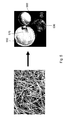
- FIG. 8 shows (a) an image of a nanofiber FSM having the TiO 2 -containing nanofibers intertwined to form porous nets, and (b) schematically a bacteria spores filter, according to one embodiment of the present invention
- FIG. 9 shows schematically an integration of the permeation and the photocatalysis of a TiO 2 -containing nanofiber membrane cup according to one embodiment of the present invention.
- FIG. 10 shows the concentration of drug released by a TiO 2 -containing nanofiber drug releaser in a solution according to one embodiment of the present invention.
- FIG. 11 shows schematically a multi-functional vest/coat made at least partially with the TiO 2 -containing, macro-sized nanofiber fabric according to one embodiment of the present invention.
- “about” or “approximately” shall generally mean within 20 percent, preferably within 10 percent, and more preferably within 5 percent of a given value or range. Numerical quantities given herein are approximate, meaning that the term “about” or “approximately” can be inferred if not expressly stated.
- photocatalysis refers to a process of the acceleration of a photoreaction in the presence of a photocatalyst.
- a photocatalyst TiO 2 captures ultraviolet light (UV) either from sunlight or fluorescent light, it forms activated oxygen from water or oxygen in the air.
- UV ultraviolet light
- chlorophyll captures sunlight to turn water and carbon dioxide into oxygen and glucose.
- the formed activated oxygen is strong enough to oxidize and decompose organic materials, pollutants or smelling gas, and kill bacteria.
- the present invention discloses methods of synthesis of macro-sized nanostructures and direct fabrications of FSMs and FSM-based 3D devices using the macro-sized nanostructures, and also potential applications in photocatalysis, writing-erasing-rewriting information, microfiltration, controlled drug release, and the likes.
- this invention in one aspect, relates to a method for synthesizing TiO 2 -containing, macro-sized nanostructures including nanofibers, nanotubes, nanowires, or any combination of them.
- TiO 2 -containing, macro-sized nanostructures are synthesized by mixing an amount of TiO 2 powders with a volume of an alkali or alkaline solution to form a mixture that is contained in a containers and sealed therein, placing the sealed container containing the mixture in an oven for heating, and then heating the mixture therein at a temperature higher than 160° C. for a period of time effective to allow TiO 2 -containing, macro-sized nanostructures to form.
- the temperature for heating the mixture is in the range of about 180-300° C.
- the period of time of heating is in the range of about 3-960 hours.
- the formed TiO 2 -containing, macro-sized nanostructures is then washed with distilled water or a dilute acid.
- the alkali solution can be one of NaOH, p KOH, LiOH, RbOH, CsOH, and any combinations of them.
- the alkaline solution can be one of Mg(OH) 2 , Ca(OH) 2 , Sr(OH) 2 , Ba(OH) 2 , and any combinations of them.
- the TiO 2 -containing, macro-sized nanostructures are formed in an environment that has no presence of a substrate that comprises Ti, such that the TiO 2 -containing, macro-sized nanostructures comprise substantially nanofibers with a typical diameter in the range of about 20 nm to 150 nm and a typical length in the range of about hundreds of micrometers to few millimeters, as shown in FIGS. 3 and 4 , for example.
- the nanofibers are substantially in the TiO 2 —B phase or titanate phase.
- TiO 2 -containing nanostructures are produced by treating the TiO 2 powders in a concentrated solution of NaOH at a temperature about 150° C. [10] or lower temperatures.
- the nanostructures were formed on a substrate that is seeded with TiO2 powders.
- the resultant nanostructures comprise substantially nanotubes that are typically about several to tens of micrometers in length.
- the synthetic process of the TiO 2 -containing, macro-sized nanostructures according to the present invention requires the heating temperature be greater than 160° C. for a period of time effective to allow TiO 2 -containing, macro-sized nanostructures to form, and therefore results in macro-sized nanofibers about hundreds of micrometers to few millimeters in length, where the macro-sized nanofibers grow in an environment that has no presence of a substrate that is seeded with TiO2 powders.
- the macro-sized nanofibers were synthesized by first adding about 0.3 g of the TiO 2 powders (Degussa P25) into about 40 mL of 10 M alkali or alkaline solution in a 150 mL Teflon-lined autoclave container. The container was then sealed and heated in an oven for about 1-7 days at a temperature substantially above 160° C. for the growth of macro-sized nanofibers in length. Other containers can also be used to practice the current invention. After the reaction (growth), the synthesized nanofibers were washed with distilled water. The synthesized nanofibers were white and pulp-like and could be used to form FSMs and/or 3D structures including cups and tubes.
- the present invention relates to TiO 2 -containing, macro-sized nanostructures synthesized according to the above method.
- the present invention relates to a synthetic nanostructure.
- the synthetic nanostructure includes a reaction product of a chemical reaction according to the formula of 2NaOH+3TiO 2 ⁇ Na 2 Ti 3 O 7 +H 2 O, where the chemical reaction takes place at a temperature higher than 160° C. for a period of time effective to allow the reaction product to form, and furthermore, the chemical reaction takes place in an environment that has no presence of a substrate that comprises Ti.
- the chemical reaction takes place in a sealed container.
- the effective temperature is in the range of about 180-300° C.
- the effective period of time is in the range of about 3-960 hours.
- a first reactant TiO 2 is provided in the form of powders, and a second reactant that comprises an inorganic base is provided in the form of solution.
- the second reactant comprises NaOH and the reaction product comprises a compound of the formula Na 2 Ti 3 O 7 .
- the compound of the formula Na 2 Ti 3 O 7 is in the form of nanofiber with a typical diameter in the range of 20 nm to 150 nm.
- the synthesized nanofibers can be used to form 2D FSMs and/or 3D structures including cups and tubes.
- a two-dimensional (2D) FSM can be formed by the following steps: at first, a plurality of TiO 2 -containing, macro-sized nanostructures are provided. Then the plurality of TiO 2 -containing, macro-sized nanostructures is cast over a template film to form a free standing membrane over the template film. Next, the free standing membrane cast over the template film is dried at a temperature for a period of time. The temperature of drying is substantially in the range of about 0-180° C. The period of time of drying is substantially in the range of about 0.5-30 hours. Finally, the dried free standing membrane is removed from the template film by calcining the dried free standing membrane over the template film at a temperature in the range of 300-600° C. for the template film of an ashless filter paper, or by hand for the template film of a polyethylene film. The template film is substantially 2D.
- the casting step has the steps of casting a first plurality of TiO 2 -containing, macro-sized nanostructures over the template film; drying the first plurality of TiO 2 -containing, macro-sized nanostructures cast over the template film at RT for a first period of time; subsequently casting at least one additional plurality of TiO 2 -containing, macro-sized nanostructures over the dried first plurality of TiO 2 -containing, macro-sized nanostructures cast over the template film; and drying the at least one additional plurality of TiO 2 -containing, macro-sized nanostructures cast over the dried first collection of TiO 2 -containing, macro-sized nanostructures cast over the template film at RT for a second period of time that is substantially different from or equal to the first period of time.
- the 2D FSM is formed with multi-layers and has a thickness in a range of from tens to hundreds of micrometers.
- the thickness of the 2D FSM is determined by the amount of TiO 2 -containing, macro-sized nanostructures cast over the template film.
- the TiO 2 -containing nanofibers in each layer are at least partially intertwined, thereby forming voids therein.
- the 2D FSM is porous, permeable and zeolitic, chemically inert, biocompatible, and/or thermally stable, as shown below.
- the above disclosed procedures can also be utility to fabricate a 3D structure directly from nanostructures.
- a template having a 3D configuration corresponding to the 3D structure to be formed is utilized, instead of a 2D film.
- the 3D structure has a wall portion formed with multi-layers.
- the TiO 2 -containing nanofibers in each layer are at least partially intertwined, thereby forming voids therein.
- the wall portion of the 3D structure has a thickness in a range of from tens to hundreds of micrometers.
- At least a portion of the 3D structure is porous, permeable and zeolitic.
- the 3D structure is chemically inert, biocompatible, and/or thermally stable.
- a process 100 for forming a nanofiber cup 150 is schematically shown according to one embodiment of the present invention.
- a macroscopic template or mold 110 is provided.
- the macroscopic template or mold 110 has a desired 3D structure and size and is made of an ashless filter-paper, a polyethylene film, or other materials.
- the macro-sized nanofibers synthesized according to the invented method(s) disclosed in this specification are cast over the macroscopic template or mold 110 .
- the cast nanofiber cup 150 cast over the macroscopic template or mold 110 is dried at a temperature in the range of about 0-180° C. in an oven for the period of time in the range of about 0.5-30 hours.
- the template or mold 110 is simply removed by hand for a plastic template or burning out via the calcination at a temperature about 500° C. for a filter paper template, thereby resulting in the nanofiber cup 150 made of the inorganic nanofibers.
- the wall (membrane) thickness of the nanofiber cup 150 varies from tens to hundreds of micrometers, depending on the amount of the nanofibers used.
- the present invention relates to a synthetic nanostructure.
- the synthetic nanostructure includes a reaction product of several chemical reactions in sequence according to the formulae of: 2NaOH+3TiO 2 ⁇ Na 2 Ti 3 O 7 ; (a) Na 2 Ti 3 O 7 +2H + ⁇ 2Na + +H 2 Ti 3 O 7 ; and (b) H 2 Ti 3 O 7 ⁇ H 2 O+TiO 2 —B, (c) where at least chemical reaction (a) takes place at a temperature higher than 160° C. for a period of time effective to allow the reaction product to form, and furthermore, the at least chemical reaction (a) takes place in an environment that has no presence of a substrate that comprises Ti.
- the effective temperature is in the range of about 180-300° C.
- the effective period of time is in the range of about 3-960 hours.
- a first reactant TiO 2 is provided in the form of powders, and a second reactant that comprises an inorganic base is provided in the form of solution.
- the second reactant in one embodiment comprises NaOH.
- the second reactant comprises OH ⁇ .
- the reaction product comprises a compound of the formula Na 2 Ti 3 O 7 .
- the compound of the formula Na 2 Ti 3 O 7 is in the form of macro-sized nanofibers with a typical diameter in the range of 20 nm to 150 nm.
- At least chemical reaction (a) takes place in a sealed container.
- Chemical reaction (b) takes place substantially between 180° C. and 300° C. for a period of time effective to allow the compound of the formula H 2 Ti 3 O 7 to form in the form of macro-sized nanofibers.
- Chemical reaction (c) takes place in a calcination process, where the calcination process can be a step of heating in a furnace at a temperature in the range of 300-600° C. in air and a step of burning in air.
- the chemical reaction (c) causes the compound of the formula TiO 2 —B to form in the form of macro-sized nanofibers, where the compound of the formula TiO 2 —B as formed in the form of macro-sized nanofibers is with a typical diameter in the range of 20 nm to 150 nm.
- the present invention can find many applications in a wide spectrum of fields, such as:
- a synthetic route for the hydrothermal synthesis of TiO 2 -containing, macro-sized nanofibers/nanowires at an effective temperature above 160° C. for an effective time period is disclosed.
- TiO 2 powder (Degussa P25) was introduced into about 40 mL of 10 M alkali solution in a 150 mL Teflon-lined autoclave container. The container was then sealed and placed in an oven for heating. After the hydrothermal reaction in the oven a temperature above 160° C. for about 7 days, a white pulp-like product of the TiO2-containing, macro-sized nanofibers was collected, washed with distilled water or a dilute acid. The washed white pulp-like product of the TiO2-containing, macro-sized nanofibers was cast on a macroscopic template made of either an ashless filter-paper (Whatman) or polyethylene film, and then dried at RT.
- a macroscopic template made of either an ashless filter-paper (Whatman) or polyethylene film, and then dried at RT.
- the casting-drying process was repeated for several times at RT, and followed thereafter by a heating at about 0-180° C. in an oven for about 0.5-30 hours. Accordingly, a 2D FSM paper or a 3D cup was formed with the TiO 2 -containing, macro-sized nanofibers on the macroscopic template. Then the macroscopic template was removed from the 2D FSM paper or the 3D cup.
- the macroscopic template includes a plastic plate or a cup.
- FIGS. 2 a and 2 b images of the nanofiber FSMs 210 and 220 , and nanofiber membrane cups 250 and 260 are shown, respectively.
- FIG. 2 a displays a plane FSM 210 and a folded FSM 220 .
- the membrane size can be varied from several to tens of centimeters, depending on the amount of the nanofiber used. In practice, it has been noticed that slowly deposited FSMs easily survived from multiple bends and folds, revealing the robust nature of the paper-like FSM formed typically by long and flexible fibers and indicating that a longer time for the nanofibers to settle on (cast over) the template would substantially increase the robustness of the FSM.
- the settling time was controlled by either the ratio of water to the nanofibers or the temperature for drying the nanofibers, or a combination of both.
- FIG. 2 a demonstrates that the plane FSM 210 could be readily folded like a piece of paper to form a folded FSM 220 , reflecting a flexible nature of the FSM formed by the long (macro-sized) nanofibers.
- the 1D nanostructure self-assembly is also shown in FIG. 14 .
- the image of a one cent coin 230 is also shown in FIG. 2 a.
- the FSM paper's flexibility could be controlled by optimizing (a) the ratio of water to the nanowires in the pulp and (b) the time for drying the nanowire pulp.
- the preparation of such robust FSM has enabled one to directly cast the long nanowires, under the help of the 3D templates or molds, into macroscopic 3D devices such as tube, bowl, and cup, as shown in FIG. 2 b .
- Such nanowire membrane devices each weighing about 0.2-0.3 g and with a nearly 500 ⁇ m wall thickness, can be freely handled by hands and trimmed with scissors, which is among the first attempts to cast at RT a pure inorganic nanofiber-containing 3D ceramic device that can be cut by scissors.
- macroscopic membrane nanofiber cups 250 and 260 were formed by casting the nanofibers over templates of an ashless filter-paper and a polyethylene film, respectively.
- the plastic template was detached by hand.
- the filter-paper template was removed by the calcination at a temperature about 500° C. or burnt out by open flames in air.
- the macroscopic membrane nanofiber cups 250 and 260 were white, weighing about 0.3 grams.
- Such inorganic nanofiber vessels were different from those cast by the traditional ceramic engineering processes involving a firing at the temperatures near or above 1,000° C.
- the image of a one cent coin 240 is also shown in FIG. 2 b.
- the successful casting of the FSMs or 3D membrane devices would depend on the morphology and spatial organization of the nanofibers.
- the long nanofibers can self-organize into the robust FSM and 3D membrane devices while nanoparticles or short nanofibers cannot. Further, the controlled assemblies of the nanofibers can determine the robustness of the 3D membrane device.
- TEM transmission electron microscope
- SEM scanning electron microscope
- FESEM field emission scanning electron microscope
- EDX energy-dispersive X-ray analyses
- XRD X-ray diffraction
- FIGS. 3 a - 3 c The SEM, FESEM and TEM images of the wall portion of a nanofiber cup according to one embodiment of the present invention were shown in FIGS. 3 a - 3 c , respectively.
- the wall portion of the nanofiber cup was formed with multi-layers of self-aggregated nanofibers.
- the number of the layers was in line with the number of times that the nanofibers had been added on the template.
- the multi-layer structure of the cup membrane indicated that the air-drying process was accompanied by a spontaneous self-organization for the nanofibers.
- the nanofibers shown in FIG. 3 a were less organized than those reported in literature [5, 8]. But, it could be anticipated that the nanofibers' organization would be improved by allowing a longer time for the self-organization at an elevated temperature, or by employing special techniques such as the “nano-logging” [11], magnetic field alignment [12], etc.
- a high resolution FESEM photographic image of the cup wall portion shown in FIG. 3 b revealed the microscopic details of the entangled nanofibers in the cup membrane, thereby forming 3D voids therein.
- the nanofibers had the diameters ranging from about 50 nm to about 100 nm, and the lengths most near about 1 mm or longer. Certain nanofibers, however, had the lengths about tens to hundreds of micrometers due probably to a continuous nucleation and/or an uneven growth commonly seen in a prolonged hydrothermal heating.
- the nanofibers in the cup wall portion were intertwined, thereby forming the 3D porous FSM with a controlled thickness about 0.1 mm. The thickness may be varied with the amount of nanofibers used.
- the 3D voids about 0.5 to 10 micrometers in size, would be ideal for the nanofibers to expand during the heating or to move around in response to a mechanical stress, thus improving the thermal stability and mechanical strength of the FSM. Practically, these 3D macropores are useful for fast mass transport in catalysis and gas storage over a wide temperature range, thus differentiating this FSM from those reported elsewhere.
- FIG. 3 c was a TEM image of the nanofibers in the cup wall portion shown in FIG. 3 b .
- the average diameter of the nanofibers was about 60 nm.
- no nanotubes could be seen in this sample under the TEM. This result was in line with what had been reported in literature that the heating temperature higher than 160° C. in the hydrothermal synthesis would mainly result in nanofibers rather than nanotubes [13].
- the hydrothermal heating temperatures above 160° C. were employed in the present invention for the purpose of forming the pulp-like and long nanofibers.
- XRD patterns of the nanofibers confirm that the 1D nanowire samples resemble the titanate in lattice structure [13].
- the titanate structure's basic building unit is a TiO 6 -octahedron [22].
- the edge-shared (TiO 6 ) octahedra would form a negatively charged layered structure.
- the countercations e.g., Na +
- sit in between the adjacent layers thus resulting in variable interlayer distances depending on the size and the hydration degree of the cation, which would explain the flexibility of the long nanofibers [23].
- FIG. 4 a shows that the inorganic nanofiber FSM retained the typical multi-layered texture after 3 hours of the calcination in a furnace at a temperature about 700° C. in air.
- FIG. 4 b displays a FESEM picture for the inorganic nanofiber FSM after the calcination at a temperature about 700° C., showing clearly the fibrous nanostructures identical to those shown in FIG. 3 b . Same results were obtained from samples being calcined at a temperature about 600° C.
- FIG. 4 b demonstrates that the calcined FSM was mainly composed of the nanofibers with the same structure shown in FIG. 3 c .
- the membrane nanofibers became much shorter and thicker than before, making the FSM no longer flexible that in turn suggested that the nanofiber structure experienced a phase transformation at about 800° C.
- the wall portion of the 3D objects still retained the characteristic multidecker structure of the entangled nanowires.
- the wall membrane became brittle. This is because the original nanowire morphology has changed to one that is typically 20 ⁇ m long and 100-400 nm wide.
- FIG. 4 c shows an X-ray powder diffraction pattern of a paper of the TiO 2 -containing long nanofibers before (410) and after (420) calcined at about 700° C. for about 3 hours.
- FIG. 5 a shows a high resolution FESEM image of a nanofiber FSM having the intertwined nanofibers.
- FIG. 5 b shows images of various 3D structures such as nanofiber cups 550 and 560 and tube 570 in comparison with an image of one cent coin 530 according to embodiments of the present invention.
- the present invention discloses methods of synthesizing TiO 2 -containing, macro-sized nanofibers and fabricating thermal-stable, robust, and multifunctional FSM-based 2D paper and 3D devices (e.g., tube, bowl, cup and so on) in nearly any macroscopic size and shape.
- Making long 1D nanostructures and then organizing them properly is critical in casting robust 2D FSMs directly out of the 1D nanomaterials.
- the inorganic 1D nanostructure is white, thermal stable, chemically inert, biocompatible, and capable of forming flexible mm-long nanofibers with the typical diameter less than 100 nm.
- Such inorganic nanofibers can form conformal membranes on macroscopic templates or molds of nearly any size for casting macroscopic vessels and tools by design.
- the nanofibers have attracted wide attentions due to their unique potentials in a wide range of applications including chemical sensing, photocatalysis, photovoltaics, varistors, gas sensors, and solar cells [9].
- the nanofiber FSM and cup vessels are easily scaled up, and ideal for mass productions due to the use of the inexpensive raw TiO 2 material. Due to the known thermal stability and chemical inertness, such inorganic nanofiber FSM catalysts can be recyclable and reusable over a wide temperature range.
- the cast inorganic nanofiber FSMs, vessels, and tools may find uses in hydrogen storage [18] and generation [19], environmental cleaning [20], sensing [21], catalytically splitting water and cracking oil, making protection mask and armor, fabricating flame-retardant fabric, filtering bacteria, photoassisted rewriting, controlled drug releases, and regenerating tissues, and the likes.
- TiO 2 -containing, macro-sized nanofibers An immediate application of the TiO 2 -containing, macro-sized nanofibers is to provide a writing-erasing-rewriting function for information storage under the help of the UV irradiation.
- TiO 2 is commonly utilized as an inexpensive and nontoxic photocatalyst. After being excited by UV light, the TiO 2 can catalyze dye degradation [25].
- TiO 2 -containing, macro-sized nanofibers Another application of the TiO 2 -containing, macro-sized nanofibers is in photocatalysis.
- the catalytic activity of the TiO 2 —B phase has been demonstrated to be better than that of other TiO 2 phases [27].
- Due to its macroporous nature, such robust nanowire-based membrane catalysts should have unique potentials for photocatalytic decompositions of organic pollutants [15] such as nerve agent simulants (NAS) [15], for example, (C2H5O) 2 P(O)(H2CSC6H5) (Aldrich).
- NAS nerve agent simulants
- the FSM made of the TiO 2 -containing, macro-sized nanofibers according to the present invention was soaked in about 10 mL of 1 mol/L Mg(NO 3 ) 2 solution at RT for about 12 hours.
- the soaked FSM was dried at RT, and then heated at a temperature above 100° C. for about 3 hours in air.
- the heated FSM is then placed in a solution containing a number of organic pollutants.
- the organic pollutants comprise NAS.
- a UV lamp Entella (model B100 AP/R) was positioned about 5 mm above the solution with the FSM for VU irradiation the solution.
- the concentrations (C t ) of the NAS were measured on a UV-visible spectrometer, for example, HP 8453 (Hewlett-Packard, Co.).
- the NAS concentration (C t ) was reduced by 67.8%, (1 ⁇ C t /C 0 ), from the initially NAS concentration (C 0 ) (about 50 mL, and 4.5 ⁇ 10 ⁇ 7 mol/L originally).
- the decomposition rate (1 ⁇ C t /C 0 ) of the NAS concentration in the case is indicated by bar 712 of FIG. 7 a , which is different from the literature results [17].
- TiO 2 is superb in photocatalytically decomposing organic pollutants including the nerve agent simulants (NAS) [15]. This is different from the catalyses on activated carbons [16] that have the dark color. Additionally, the TiO 2 photocatalytic activity can be greatly enhanced by the presence of Mg(II) [17].
- the photocatalytic properties of the nanofiber FSM were studied at the RT in the aqueous solutions of the NAS that was the diethyl phenylthiomethylphosphonate (DPTMP, C 11 H 17 O 3 PS) (Alfa Aesar).
- the nanofiber FSM was firstly pretreated through a soaking in the solution of about 1 mol/L Mg(NO 3 ) 2 for about 12 hours at RT, then dried at RT and heated in air at a temperature above 100° C. for about 3 hours.
- the NAS solution was prepared by dissolving about 45 ⁇ mol of the DPTMP into about 100 mL water containing about 10 mg of the pretreated FSM.
- the NAS concentration (C t ) in the solution was reduced by 98% (1 ⁇ C t /C 0 ), as indicated by bar 722 of FIG.
- This 98% catalytic conversion may be further improved by the optimizations of the reaction temperature, the time and the intensity of the UV radiation, and the structure and morphology as well as loading of the Mg-species.
- This 98% conversion is among the highest in the fast photocatalytic decomposition of the NAS in water at RT, indicating an unusual potential of the nanofiber FSM catalysts for making, for instance, new masks in civil defense applications.
- uses of the nanofiber FSM catalysts can minimize the downstream recovery of the powdery catalysts and at the same time eliminate the use of the catalytic supports and binders.
- the nanofiber FSMs and 3D devices according to the present invention can find applications in the filtration of particles.
- aqueous suspensions of polystyrene latex microspheres including Alfa Aesar microspheres with 0.75, 1, 2, and 2.5 ⁇ m in diameter were provided for investigating the permeability of the nanowire membrane [5].
- Each aqueous suspension had a concentration of 0.0025% (wt).
- the microfiltration using a TiO 2 -containing nanofiber cup (filter) was conducted within about 5 minutes. It had been shown that no 2- ⁇ m microspheres were detected in about 1 mL of the filtered sample (aqueous suspension). Those of 0.75 ⁇ m and 1 ⁇ m microspheres, however, penetrated the wall of the filter in the parallel tests, suggesting a size-exclusion function of the 3D devices in filtrations of micrometer-sized particles.
- the TiO 2 -containing nanofiber membrane can be used for filtrations of bacteria spores in civil defense, environmental cleaning, neuron growth media to repair injured spinal cord, treatments of Alzheimer's and Parkinson's diseases, inject-able bone repair, portable MEMS (Micro Electro Mechanical Sensor) biosensors and membrane chem-sensors.
- FIG. 8 a shows an image of a nanofiber FSM having the TiO 2 -containing nanofibers intertwined to form porous nets, which is used for the filtration of particles.
- FIG. 8 b shows schematically a bacteria spores filtration using intertwined nanofibers.
- the TiO 2 -containing nanofiber membrane cup 910 was pretreated in a Mg(II) solution according to the method as shown in EXAMPLES 3 and 4, and then was filled with a NAS solution 920 .
- the cup 910 containing the NAS solution 920 was irradiated by a UV light 930 emitted for a UV lamp (Entela, model B100 AP/R) from one side of the cup 910 , as shown in FIG. 9 .
- Macroporous 3D devices walled by the scaffolding nanowires/nanofibers, are useful in controlling drug release [29].
- a section of the TiO 2 -containing nanofiber FSM (74.0 mg) was pre-soaked in about 100 mL solution of about 0.001 mol/L crystal violet for about 12 hours at RT, and then placed in about 10 mL of fresh water at RT.
- the controlled drug release was monitored by the HP 8453 UV-visible spectrometer. After every 24 hours of the drug release, the TiO 2 -containing nanofiber FSM was transferred into another 10 mL of fresh water.
- FIG. 10 shows the concentration of drug released from the TiO 2 -containing nanofiber FSM in the solution, which indicated that the controlled drug release reached a maximum at about 24 hours, and was effective for at least 4 days.
- the 3D scaffolds of the TiO 2 -containing nanofiber/nanowires after being coated with growth hormone, is very useful in directing the growth of stem cells for potential applications in regenerative medicine [30, 31].
- Ceramic titanate nanowire is environmentally benign, biocompatible, chemically inert, surface functionalization easy, inexpensive, and thermally stable.
- a new composite is formed and usable for making tires.
- the new composite comprises TiO 2 -containing, macro-sized nanowires/nanofiber that are blended with rubber polymer.
- the NW-rubber composite can be grey in color, and may provide the new tire with better interfacing with polymer backbone, higher mechanical strength and lighter in weight or better gas mileage, and easier in handling on wet roadway.
- the NW could be short or long, depending on the application need.
- the short NW is made at a temperature around 150-160° C. within a few hours.
- the long NW is made at a temperature above 160° C. and with a reaction time longer than 1 day.
- the TiO 2 -containing, macro-sized nanofibers according to the present invention is also usable in making a multi-functional vest/coat for nanomedicine, battlefield, sports, space, firefighter, and the likes.
- a multi-functional vest/coat 1300 is made at least partially with the TiO 2 -containing, macro-sized nanofiber fabric.
- the multi-functional vest/coat 1300 has a plurality of areas 1330 in a front and back panel 1310 and 1320 of the vest/coat 1300 , which is made of the TiO 2 -containing, macro-sized nanofiber fabric.
- Each of the plurality of areas includes one or more of a minimum-invasion nanodrug delivery MEMS 1332 , heating-releasing cartridge of nanodrugs 1334 , electrochemical nanobiosensor 1336 , and the likes.
- These minimum-invasion nanodrug delivery MEMS 1332 , heating-releasing cartridge of nanodrugs 1334 , and electrochemical nanobiosensor 1336 are controllable, individually or in combination.
Abstract
Description
2NaOH+3TiO2═Na2Ti3O7+H2O,
where the chemical reaction takes place at a temperature higher than 160° C. for a period of time effective to allow the reaction product to form, and where the chemical reaction takes place in an environment that has no presence of a substrate that comprises Ti. In one embodiment, the chemical reaction takes place in a sealed container. The effective temperature is in the range of about 180-300° C. The effective period of time is in the range of about 3-960 hours.
2NaOH+3TiO2→Na2Ti3O7; (a)
Na2Ti3O7+2H+→2Na++H2Ti3O7; and (b)
H2Ti3O7→H2O+TiO2—B, (c)
where at least chemical reaction (a) takes place at a temperature higher than 160° C. for a period of time effective to allow the reaction product to form, and where at least chemical reaction (a) takes place in an environment that has no presence of a substrate that comprises Ti. In one embodiment, the effective temperature is in the range of about 180-300° C. The effective period of time is in the range of about 3-960 hours.
2NaOH+3TiO2═Na2Ti3O7+H2O,
where the chemical reaction takes place at a temperature higher than 160° C. for a period of time effective to allow the reaction product to form, and furthermore, the chemical reaction takes place in an environment that has no presence of a substrate that comprises Ti. In one embodiment, the chemical reaction takes place in a sealed container. The effective temperature is in the range of about 180-300° C. The effective period of time is in the range of about 3-960 hours.
2NaOH+3TiO2→Na2Ti3O7; (a)
Na2Ti3O7+2H+→2Na++H2Ti3O7; and (b)
H2Ti3O7→H2O+TiO2—B, (c)
where at least chemical reaction (a) takes place at a temperature higher than 160° C. for a period of time effective to allow the reaction product to form, and furthermore, the at least chemical reaction (a) takes place in an environment that has no presence of a substrate that comprises Ti. In one embodiment, the effective temperature is in the range of about 180-300° C. The effective period of time is in the range of about 3-960 hours.
-
- (1). membrane catalysts (no binders/supports/down-stream separations),
- (2). catalytic supports (membrane macropores support catalyst particles),
- (3). catalytically decomposing pollutants, e.g., nerve agents, in water under UV light, about 12 times more powerful than the commercial TiO2 powder,
- (4). drug delivery (DNA, protein, and organic drugs can be stored in the voids or macropores for slow or controlled releases),
- (5). tissue regeneration (tissue cells can grow in the biocompatible voids),
- (6). solar cell and water photo-splitting,
- (7). oil cracking,
- (8). making and storing hydrogen for fuel cells,
- (9). writing-erasing-rewriting of information,
- (10). making multi-functional vests/coats for nanomedicine, battlefield and firefighter, etc., and
- (11). making tire for vehicles.
- [1]. Xia, Y., Yang, P., Sun, Y., Wu, Y., Mayers, B., Gates, B., Yin, Y., Kim, F., Yan, H. Adv. Mater. 2003, 15, 353.
- [2]. (a) Whaley, S. R., English, D. S., Hu, E. L., Barbara, P. F., Belcher, A. M. Nature 2000, 405, 665. (b) Wei, B. Q., Vajtai, R., Jung, Y., Ward, J., Zhang, R., Ramanath, G., Ajayan, P. M. Chem. Mater. 2003, 15, 1598. (c) Yamaguchi, A., Uejo, F., Yoda, T., Uchida, T., Tanamura, Y., Yamashita, T., Teramae N. Nature Mater. 2004, 3, 337. (d) Jackson, A. M., Myerson, J. W., Stellacci F. Nature Mater. 2004, 3, 330.
- [3]. Yang, H., Kuperman, A., Coombs, N., Mamiche-A., S., Ozin, G. A. Nature, 1996, 379, 703.
- [4]. Ostomel, T. A., and Stucky, G. D. Chem. Commun. 2004, 1016
- [5]. Yuan J., Laubernds K., Villegas J., Gomez S., Suib S. L. Adv. Mat. 2004, 16, 1729.
- [6]. Gu G., Schmid M., Chiu P.-W., Minett A, Fraysse J., Kim G.-T., Roth S., Kozlov M., Muñoz E., Baughman R. H. Nature Mat. 2003, 2, 316.
- [7]. Endo M., Muramatsu H., Hayashi T., Kim Y. A., Terrones M., Dresselhaus M. S. Nature 2005, 433, 476.
- [8]. Zhang M., Fang S., Zakhidov A. A., Lee S. B., Aliev A. E., Williams C. D., Atkins K. R., Baughman R. H. Science, 2005, 309, 1215.
- [9]. (a) Adachi, M., Murata, Y., Yoshikawa, S. Chem. Lett. 2000, 8, 942. (b) Uchida, S., Chiba, R., Tomiha, M., Masaki, N., Shirai,
M. Electrochemistry 2002, 70, 418. (c) Adachi, M., Okada, I., Ngamsinlapasathian, S., Murata, Y., Yoshikawa,S. Electrochemistry 2002, 70, 449. (d) Hippe, C., Wark, M., Lork, E., Schulz-Ekloff, G. Microporous Mesoporous Mater. 1999, 31, 235. (e) Khitrov, G. MRS Bull. 2000, 25, 3. (f) Zhang, M., Bando, Y., Wada, K. J. Mater. Sci. Lett. 2001, 20, 167. (g) Zhang, M., Bando, Y., Wada, K. J. Mater. Res. 2001, 16, 1408. (h) Li, D., Xia, Y. N. Nano Lett. 2003, 3, 555. (i) Hoyer,P. Langmuir 1996, 12, 1411. (j) Liu, S. M., Gan, L. M., Liu, L. H., Zhang, W. D., Zeng, H. C. Chem. Mater. 2002, 14, 1391. (k) Kasuga, T., Hiramatsu, M., Hoson, A., Sekino, T., Niihara, K. Langmuir 1998, 14, 3160. (l) Kasuga, T., Hiramatsu, M., Hoson, A., Sekino, T., Niihara, K. Adv. Mater. 1999, 11, 1307. (m) Imai, H., Takei, Y., Shimizu, K., Matsuda, M., Hirashima, H. J. Mater. Chem. 1999, 9, 2971. - [10]. Tian, Z. R., Voigt, J, A., Liu, J., Mckenzie, B., Xu, H., J. Am. Chem. Soc., 2003, 125, 12384.
- [11]. Whang, D., Jin, S., Wu, Y. & Lieber, C. M. Nano Lett. 2003, 3, 1255.
- [12]. Tolbert, S. H., Firouzi, A., Stucky, G. D., Chmelka, B. F., Science 1997, 278: 264.
- [13]. (a) Armstrong, A. R., Armstrong, G., Canales, J., Garcia, R., Bruce, P. G., Adv. Mater. 2005, 17, 862, (b) Armstrong, A. R., Armstrong, G., Canales, J., Bruce, P. G., Angew. Chem. Int. Ed. 2004, 43, 2286, (c) Yoshida, R., Suzuki, Y., Yoshikawa, S., J. Solid State Chem. 2005, 178, 2179,
- [14]. (a) Marchand, R., Brohan, L., Tournoux, M., Mater. Res. Bull., 1980, 15, 1129, (b) Feist, T. P., Davies, P. K. J. Solid State Chem. 1992, 101, 275, (c) Yoshida, R., Suzuki, Y., Yoshikawa, S. J Solid State Chem. 2005, 178, 2179.
- [15]. (a) Thompson, T. L., Yates, J. T., Jr. Topics in Catalysis 2005, 35(3-4), 197, (b) Thompson, T. L., Panayotov, D. A., Yates, J. T., Jr J. Phys. Chem. B 2004, 108(43), 16825, (c) Rusu, C. N., Yates, J. T., Jr J. Phys. Chem. B 2000, 104(51), 12299, (d) Rusu, C. N., Yates, J. T., Jr. J. Phys. Chem. B 2000, 104(51), 12292. (e) Moss, J. A., Szczepankiewicz, S. H., Park, E., Hoffman, M. R. J. Phys. Chem. B. 2005, 109, 19779.
- [16]. 16. Surface and bulk measurements of metals deposited on activated carbon, S. H. Park, S. McClain, Z. R. Tian, O. Giraldo, H. Zhou, S. L. Suib, C. Karwacki, Chem. Mater. 1997, 9, 176
- [17]. (a) Machli, M., Lemonidou, A. A. Catalysis Lett. 2005, 99, 221. (b) Tanabe, K., Hattori, H., Sumiyoshi, T., Tamaru, K., Kondo, T. J.
Catalysis 1978, 53, 1. - [18]. (a) Bavykin, D. V., Lapkin, A. A., Plucinski, P. K., Friedrich, J. M., Walsh, F. C. J. Phys. Chem. B 2005, 109, 19422. (b) Lim, S. H., Luo, J., Zhong, Zi., Ji, W., Lin, J. Inorg. Chem. 2005, 44, 4124.
- [19]. (a) Lin, C.-H., Lee, C.-H., Chao, J.-H., Kuo, C.-Y., Cheng, Y.-C., Huang, W.-N., Chang, H.-W., Huang, Y.-M., Shih, M.-K. Catalysis Lett. 2004, 98, 61. (b) Yin, S. F., Xu, B. Q., Zhu, W. X., Ng, C. F., Zhou, X. P., Au, C. T. Catalysis Today 2004, 93, 27. (c) Zein, S. H. S., Mohamed, A. R. Energy &
Fuels 2004, 18, 1336. - [20]. Mor, G. K., Carvalho, M. A., Varghese, O. K., Pishko, M. V., Grimes, C. A. J. Mater. Res. 2004, 19, 628.
- [21]. (a) Liu, S., Chen, A. Langmuir 2005, 21, 8409. (b) Varghese, O. K., Grimes, C. A. J. Nanosci. Nanotech. 2003, 3, 277. (c) Grimes, C. A., Ong, K. G., Varghese, O. K., Yang, X., Paulose, M., Dickey, E. C., Ruan, C., Pishko, M. V., Kendig, J. W., Mason, A. J. Sensors. 2003, 3, 69.
- [22]. (a) Kim, Y. I., Salim, S., Huq, M., Mallouk, T. E. J. Am. Chem. Soc. 1991, 113, 9561. (b) Sasaki, T., Watanabe, M., Hashizume, H., Yamada, H., Nakazawa, H. J. Am. Chem. Soc. 1996, 118, 8329. (c) Sukpirom, N., Lerner, M. M. Chem. Mater. 2001, 13, 2179. (d) Izawa, H., Kikkawa, S., Koizumi, M. J. Phys. Chem. 1982, 86, 5023.
- [23]. (a) Andersson, S., Wadsley, A. D. Acta Crystallogr. 1961, 14, 1245. (b) Andersson, S., Wadsley, A. D. Acta Crystallogr. 1962, 15, 194.
- [24]. (a) Feist, T., Davies, P. K. J. Solid State Chem. 1992, 101, 275. (b) Zukalova, M., Kalbac, M., Kavan, L., Exnar, I., Graetzel, M., Zukalova, M. Chem. Mater. 2005, 17, 1248.
- [25]. Senthilkumaar, S., Porkodi, K. J. Colloid Interface Sci. 2005, 288, 184.
- [26]. Kishimura, A., Yamashita, T., Yamaguchi, K., Aida, T. Nature Mater. 2005, 4, 546.
- [27]. Papachryssanthou, J., Bordes, E., Vejux, A., Courtine, P., Marchand R., Tournoux, M. Catal.
Today 1987, 1, 219. - [28]. Thompson, T. L., Yates, J. T., Jr. Top. Catal. 2005, 35, 197.
- [29]. Brokx, R. D., Bisland, S. K., Gariepy, J. J. Controlled Release 2002, 78, 115.
- [30]. Silva, G. A., Czeisler, C, Niece, K. L., Beniash, E., Harrington, D. A., Kessler, J. A., Stupp, S. I. Science 2004, 303, 1352.
- [31]. Stevens, M. M., Marini, R. P., Schaefer, D., Aronson, J., Langer, R., Shastri, V. P. Proc. Natl. Acad. Sci. U.S.A. 2005, 102, 11450.
Claims (11)
Priority Applications (4)
| Application Number | Priority Date | Filing Date | Title |
|---|---|---|---|
| US11/653,189 US8883115B2 (en) | 2006-01-12 | 2007-01-12 | TiO2 nanostructures, membranes and films, and methods of making same |
| EP07814882A EP2101687A2 (en) | 2007-01-12 | 2007-09-17 | Biocompatible scaffold for sensing proteins |
| CN2007800497563A CN101646401B (en) | 2007-01-12 | 2007-09-17 | Biocompatible scaffold for sensing proteins |
| PCT/US2007/078634 WO2008088588A2 (en) | 2007-01-12 | 2007-09-17 | Biocompatible scaffold for sensing proteins |
Applications Claiming Priority (3)
| Application Number | Priority Date | Filing Date | Title |
|---|---|---|---|
| US75849206P | 2006-01-12 | 2006-01-12 | |
| US78564906P | 2006-03-23 | 2006-03-23 | |
| US11/653,189 US8883115B2 (en) | 2006-01-12 | 2007-01-12 | TiO2 nanostructures, membranes and films, and methods of making same |
Publications (2)
| Publication Number | Publication Date |
|---|---|
| US20100255285A1 US20100255285A1 (en) | 2010-10-07 |
| US8883115B2 true US8883115B2 (en) | 2014-11-11 |
Family
ID=38846147
Family Applications (3)
| Application Number | Title | Priority Date | Filing Date |
|---|---|---|---|
| US11/653,192 Expired - Fee Related US7931812B2 (en) | 2006-01-12 | 2007-01-12 | TiO2 nanostructures, membranes and films, and applications of same |
| US11/653,189 Expired - Fee Related US8883115B2 (en) | 2006-01-12 | 2007-01-12 | TiO2 nanostructures, membranes and films, and methods of making same |
| US13/080,592 Abandoned US20120051973A1 (en) | 2006-01-12 | 2011-04-05 | TiO2 NANOSTRUCTURES, MEMBRANES AND FILMS, AND APPLICATIONS OF SAME |
Family Applications Before (1)
| Application Number | Title | Priority Date | Filing Date |
|---|---|---|---|
| US11/653,192 Expired - Fee Related US7931812B2 (en) | 2006-01-12 | 2007-01-12 | TiO2 nanostructures, membranes and films, and applications of same |
Family Applications After (1)
| Application Number | Title | Priority Date | Filing Date |
|---|---|---|---|
| US13/080,592 Abandoned US20120051973A1 (en) | 2006-01-12 | 2011-04-05 | TiO2 NANOSTRUCTURES, MEMBRANES AND FILMS, AND APPLICATIONS OF SAME |
Country Status (3)
| Country | Link |
|---|---|
| US (3) | US7931812B2 (en) |
| EP (2) | EP1993675A4 (en) |
| WO (2) | WO2008060309A2 (en) |
Cited By (1)
| Publication number | Priority date | Publication date | Assignee | Title |
|---|---|---|---|---|
| US10828400B2 (en) | 2014-06-10 | 2020-11-10 | The Research Foundation For The State University Of New York | Low temperature, nanostructured ceramic coatings |
Families Citing this family (11)
| Publication number | Priority date | Publication date | Assignee | Title |
|---|---|---|---|---|
| JP4579935B2 (en) * | 2007-01-17 | 2010-11-10 | セイコーエプソン株式会社 | Photoelectric conversion element and electronic device |
| ES2375187T3 (en) * | 2007-08-29 | 2012-02-27 | Vito Nv | PROCEDURE TO PRODUCE A CONSTRUCTION OF THREE-DIMENSIONAL MACROPOROUS FILAMENTS BASED ON PHASE INVESTMENT AND CONSTRUCTION OBTAINED FROM THAT MODE. |
| KR101332526B1 (en) * | 2008-06-20 | 2013-11-22 | 오사까 가스 가부시키가이샤 | Titanium oxide structure and porous titanium oxide composition |
| PL2459282T3 (en) * | 2009-07-31 | 2013-11-29 | Council Scient Ind Res | Removal of organic dyes and organic pollutants by titanium peroxide gel |
| WO2012058517A2 (en) * | 2010-10-28 | 2012-05-03 | Novarials Corporation | Ceramic nanowire membranes and methods of making the same |
| US20140076404A1 (en) * | 2010-12-15 | 2014-03-20 | Mei-Chee Tan | Ir-activated photoelectric systems |
| EP3002013A1 (en) * | 2014-10-02 | 2016-04-06 | Aero Engineering, S.L. | Air sterilizing unit |
| CN105032499A (en) * | 2015-06-26 | 2015-11-11 | 铱格斯曼航空科技集团有限公司 | Novel FexTiO2-yCy nano fiber preparation method |
| CN109718856A (en) * | 2019-01-14 | 2019-05-07 | 武汉工程大学 | Photochemical catalyst and its preparation method and application based on phosphonic acid ligand |
| US20220290085A1 (en) * | 2019-08-09 | 2022-09-15 | Board Of Trustees Of The University Of Arkansas | Cell-sensory bioscaffolds, fabrication methods and applications of same |
| CN113511638B (en) * | 2021-06-30 | 2022-12-06 | 南京邮电大学 | Preparation method of TiN-S composite anode material by plasma chemical vapor codeposition |
Citations (25)
| Publication number | Priority date | Publication date | Assignee | Title |
|---|---|---|---|---|
| US6113861A (en) | 1996-07-02 | 2000-09-05 | Tao, Inc. | Photocatalyst sheet |
| US6162755A (en) | 1997-09-29 | 2000-12-19 | Elf Atochem North American, Inc. | Heterogeneous organotin catalysts |
| US6409928B1 (en) | 1997-01-31 | 2002-06-25 | Lynntech, Inc. | Photocatalytic oxidation of organics using a porous titanium dioxide membrane and an efficient oxidant |
| US6409961B1 (en) | 1996-12-26 | 2002-06-25 | Sumitomo Chemical Co., Ltd. | Titania fiber, method for producing the fiber and method for using the fiber |
| US20020098977A1 (en) | 2000-11-28 | 2002-07-25 | Korea Research Institute Of Chemical Technology | Titania photocatalyst and its preparing method |
| US6503831B2 (en) | 1997-10-14 | 2003-01-07 | Patterning Technologies Limited | Method of forming an electronic device |
| CN1400169A (en) | 2002-08-19 | 2003-03-05 | 西安华创纳米化合物技术研究发展有限责任公司 | Preparation method of titanium oxide nano fibre |
| US6551536B1 (en) | 2001-07-30 | 2003-04-22 | Saehan Industries Incorporation | Reverse osmosis membrane having excellent anti-fouling property and method for manufacturing the same |
| US6576589B1 (en) | 1999-09-20 | 2003-06-10 | Lg Electronics Inc. | Method for making anatase type titanium dioxide photocatalyst |
| US6613301B2 (en) | 2000-04-07 | 2003-09-02 | Korea Institute Of Geosciencie And Mineral Resources | Method for producing nanometer-sized ultrafine titanium dioxide |
| US20030183576A1 (en) | 2001-03-19 | 2003-10-02 | Tomomi Ohara | Composite semipermeable membrane,method for preparing the same, and method for water treatment using the same |
| US20030215355A1 (en) | 2002-05-14 | 2003-11-20 | Nanoscale Materials, Inc. | Method and apparatus for control of chemical or biological warfare agents |
| US20040131934A1 (en) * | 2001-03-20 | 2004-07-08 | Francois Sugnaux | Mesoporous network electrode for electrochemical cell |
| US6808561B2 (en) | 2000-10-16 | 2004-10-26 | University Of South Carolina | Biocompatible cement containing reactive calcium phosphate nanoparticles and methods for making and using such cement |
| US6855202B2 (en) | 2001-11-30 | 2005-02-15 | The Regents Of The University Of California | Shaped nanocrystal particles and methods for making the same |
| US20050061732A1 (en) | 2001-09-26 | 2005-03-24 | Andre Grangeon | Novel inorganic nanofiltration membranes |
| US6872249B2 (en) | 2000-10-04 | 2005-03-29 | The Board Of Trustees Of The University Of Arkansas | Synthesis of colloidal nanocrystals |
| US6902653B2 (en) | 1999-11-22 | 2005-06-07 | Titan Technologies | Apparatus and method for photocatalytic purification and disinfection of fluids |
| US6914279B2 (en) | 2002-06-06 | 2005-07-05 | Rutgers, The State University Of New Jersey | Multifunctional biosensor based on ZnO nanostructures |
| US20050158207A1 (en) | 2002-05-14 | 2005-07-21 | Lanz Bret E. | Method and apparatus for control of chemical or biological warfare agents |
| US6921476B2 (en) | 2002-09-11 | 2005-07-26 | Kabushiki Kaisha Toshiba | UV-assisted advanced-ozonation water treatment system and advanced-ozonation module |
| US20060078726A1 (en) | 2003-10-10 | 2006-04-13 | Antonio Jose A T | Nanostructured titanium oxide material and its synthesis procedure |
| US20060188774A1 (en) | 2004-12-09 | 2006-08-24 | Nanosys, Inc. | Nanowire-based membrane electrode assemblies for fuel cells |
| US20060193766A1 (en) | 2003-04-15 | 2006-08-31 | Akira Hasegawa | Titania nanotube and method for producing same |
| US20070284303A1 (en) | 2004-08-23 | 2007-12-13 | Christopher Drew | Nanometer scale structures |
Family Cites Families (9)
| Publication number | Priority date | Publication date | Assignee | Title |
|---|---|---|---|---|
| US5174877A (en) * | 1986-07-24 | 1992-12-29 | Photo-Catalytics, Inc. | Apparatus for photocatalytic treatment of liquids |
| US5035784A (en) * | 1987-07-27 | 1991-07-30 | Wisconsin Alumni Research Foundation | Degradation of organic chemicals with titanium ceramic membranes |
| US5759939A (en) * | 1994-04-08 | 1998-06-02 | Kansas State University Research Foundation | Composite metal oxide adsorbents |
| US6027775A (en) * | 1996-09-30 | 2000-02-22 | Chubu Electric Power Co., Inc. | Crystalline titania and process for producing the same |
| US5849201A (en) * | 1997-06-02 | 1998-12-15 | Mva Inc. | Oxidation of aromatic hydrocarbons |
| IL129564A (en) * | 1999-04-23 | 2004-06-20 | Atlantium Lasers Ltd | Method for disinfecting and purifying liquids and gases and a device to use therein |
| US6403653B1 (en) * | 2000-06-02 | 2002-06-11 | The United States Of America As Represented By The Secretary Of The Army | Active topical skin protectants using reactive nanoparticles |
| US6686594B2 (en) * | 2001-10-29 | 2004-02-03 | Air Products And Chemicals, Inc. | On-line UV-Visible light halogen gas analyzer for semiconductor processing effluent monitoring |
| US7579077B2 (en) * | 2003-05-05 | 2009-08-25 | Nanosys, Inc. | Nanofiber surfaces for use in enhanced surface area applications |
-
2007
- 2007-01-12 WO PCT/US2007/000885 patent/WO2008060309A2/en active Application Filing
- 2007-01-12 US US11/653,192 patent/US7931812B2/en not_active Expired - Fee Related
- 2007-01-12 EP EP07866983A patent/EP1993675A4/en not_active Withdrawn
- 2007-01-12 US US11/653,189 patent/US8883115B2/en not_active Expired - Fee Related
- 2007-01-12 EP EP07835659A patent/EP1993717A4/en not_active Withdrawn
- 2007-01-12 WO PCT/US2007/000952 patent/WO2008002333A2/en active Application Filing
-
2011
- 2011-04-05 US US13/080,592 patent/US20120051973A1/en not_active Abandoned
Patent Citations (25)
| Publication number | Priority date | Publication date | Assignee | Title |
|---|---|---|---|---|
| US6113861A (en) | 1996-07-02 | 2000-09-05 | Tao, Inc. | Photocatalyst sheet |
| US6409961B1 (en) | 1996-12-26 | 2002-06-25 | Sumitomo Chemical Co., Ltd. | Titania fiber, method for producing the fiber and method for using the fiber |
| US6409928B1 (en) | 1997-01-31 | 2002-06-25 | Lynntech, Inc. | Photocatalytic oxidation of organics using a porous titanium dioxide membrane and an efficient oxidant |
| US6162755A (en) | 1997-09-29 | 2000-12-19 | Elf Atochem North American, Inc. | Heterogeneous organotin catalysts |
| US6503831B2 (en) | 1997-10-14 | 2003-01-07 | Patterning Technologies Limited | Method of forming an electronic device |
| US6576589B1 (en) | 1999-09-20 | 2003-06-10 | Lg Electronics Inc. | Method for making anatase type titanium dioxide photocatalyst |
| US6902653B2 (en) | 1999-11-22 | 2005-06-07 | Titan Technologies | Apparatus and method for photocatalytic purification and disinfection of fluids |
| US6613301B2 (en) | 2000-04-07 | 2003-09-02 | Korea Institute Of Geosciencie And Mineral Resources | Method for producing nanometer-sized ultrafine titanium dioxide |
| US6872249B2 (en) | 2000-10-04 | 2005-03-29 | The Board Of Trustees Of The University Of Arkansas | Synthesis of colloidal nanocrystals |
| US6808561B2 (en) | 2000-10-16 | 2004-10-26 | University Of South Carolina | Biocompatible cement containing reactive calcium phosphate nanoparticles and methods for making and using such cement |
| US20020098977A1 (en) | 2000-11-28 | 2002-07-25 | Korea Research Institute Of Chemical Technology | Titania photocatalyst and its preparing method |
| US20030183576A1 (en) | 2001-03-19 | 2003-10-02 | Tomomi Ohara | Composite semipermeable membrane,method for preparing the same, and method for water treatment using the same |
| US20040131934A1 (en) * | 2001-03-20 | 2004-07-08 | Francois Sugnaux | Mesoporous network electrode for electrochemical cell |
| US6551536B1 (en) | 2001-07-30 | 2003-04-22 | Saehan Industries Incorporation | Reverse osmosis membrane having excellent anti-fouling property and method for manufacturing the same |
| US20050061732A1 (en) | 2001-09-26 | 2005-03-24 | Andre Grangeon | Novel inorganic nanofiltration membranes |
| US6855202B2 (en) | 2001-11-30 | 2005-02-15 | The Regents Of The University Of California | Shaped nanocrystal particles and methods for making the same |
| US20030215355A1 (en) | 2002-05-14 | 2003-11-20 | Nanoscale Materials, Inc. | Method and apparatus for control of chemical or biological warfare agents |
| US20050158207A1 (en) | 2002-05-14 | 2005-07-21 | Lanz Bret E. | Method and apparatus for control of chemical or biological warfare agents |
| US6914279B2 (en) | 2002-06-06 | 2005-07-05 | Rutgers, The State University Of New Jersey | Multifunctional biosensor based on ZnO nanostructures |
| CN1400169A (en) | 2002-08-19 | 2003-03-05 | 西安华创纳米化合物技术研究发展有限责任公司 | Preparation method of titanium oxide nano fibre |
| US6921476B2 (en) | 2002-09-11 | 2005-07-26 | Kabushiki Kaisha Toshiba | UV-assisted advanced-ozonation water treatment system and advanced-ozonation module |
| US20060193766A1 (en) | 2003-04-15 | 2006-08-31 | Akira Hasegawa | Titania nanotube and method for producing same |
| US20060078726A1 (en) | 2003-10-10 | 2006-04-13 | Antonio Jose A T | Nanostructured titanium oxide material and its synthesis procedure |
| US20070284303A1 (en) | 2004-08-23 | 2007-12-13 | Christopher Drew | Nanometer scale structures |
| US20060188774A1 (en) | 2004-12-09 | 2006-08-24 | Nanosys, Inc. | Nanowire-based membrane electrode assemblies for fuel cells |
Non-Patent Citations (42)
| Title |
|---|
| Armstrong, A.R., et al., "TiO2-B Nanowires", Angewandte Chemie. International Edition, Apr. 19, 2004, pp. 2286-2288, vol. 43, Wiley-VCH Verlag GmbH & Company. |
| Armstrong, Graham, et al., "Nanotubes with the TiO2-B Structure", Chemical Communications, Jan. 1, 2005, pp. 2454-2456, No. 19, The Royal Society of Chemistry. |
| Baglioni, P. et al., "Structrual arrest in concentrated cytochrome C solutions: the effect of pH and salts", J. Phys: Condens. Matter, 2004, 16, S5003. |
| Bard, A. J. et al., "Electrochemistry and Electrogenerated Chemiluminescence from Silicon Nanocrystal Quantum Dots", Electrochemical Methods, Fundamentals and Applications, 2nd ed.; Wiley: New York, 2001. |
| Barker, P. D. et al., "pH-Linked Conformational Regulation of a Metalloprotein Oxidation-Reduction Equilibrium: Electrochemical Analysis of the Alkaline Form of Cytochrome c", J. Am. Chem. Soc., 1992, 114, 3619. |
| Bavykin, Dmitry, et al., "The Effect of Hydrothermal Conditions on the Mesoporous Structure of TiO2 Nanotubes", Journal of Materials Chemistry, Jan. 1, 2004, pp. 3370-3377, vol. 14, The Royal Society of Chemistry. |
| Cosnier, S. et al., "Mesoporous TiO2 Films: New Catalytic Electode Materials for Fabricating Amperometric Biosensors Based on Oxidases", Electroanalysis., 1997, vol. 9, No. 18, 1387. |
| D.V. Bavykin et al., A novel cation-binding TiO2 nanotube substrate for electro- and bioelectro-catalysis, Electrochemistry Communications, 2005, p. 1050-1058, vol. 7, No. 10. |
| Dong, W. et al., "Multifunctional, Catalytic Nanowire Membranes and the Membrane-Based 3D Devices", J. Phys. Chem. 2006, 16819. |
| Ellis-Behnke, R. G. et al., "Nano neuro knitting: Peptide nanofiber scaffold for brain repair and axon regeneration with functional return of vision", Proc. Natl. Acad. Sci. USA, 2006, vol. 103. No. 13, 5054-5059. |
| Emmanuel Topoglidis et al., Direct Electrochemistry and Nitric Oxide Interaction of Heme Proteins Adsorbed on Nanocyrstalline Tin Oxide Electrodes, Langmuir, 2003, p. 6894-6900, vol. 19, No. 17. |
| Gu, Gang, "V2O5 Nanofibre Sheet Actuators", Nature Materials, Jan. 1, 2003, pp. 316-319, vol. 2, No. 5, Nature Publishing Group. |
| Heimburg, T. et al., "Investigation of Secondary and Tertiary Structural Changes of Cytochrome c in Complexes with Anionic Lipids Using Amide Hydrogen Exchange Measurements: An FTIR Study", Biophys. J., 1993, 65, 2408. |
| Kokubo, T. et al., "Novel bioactive materials with different mechanical properties", Biomaterials, 2003, 24, 2161. |
| Leng, Y. et al., "Deformation behavior of titanium nitride film prepared by plasma immersion ion implantation and deposition", Surf. Coat. Technol., 2002, 156(1-3), 295. |
| Liao, S. S. et al., "Hierarchiaclly Biomimetic Bone Scaffold Materials: Nano-HA/Collagen/PLA Composite", J. Biomed. Mater. Res., 2004, 69B(2) , 158. |
| Liu, A. et al., "Direct Electrochemistry of Myoglobin in Titanate Nanotubes Film", Anal.Chem., 2005, 77, 8068. |
| McKenzie, K. J. et al., "Accumulation and Reactivity of the Redox Protein Cytochrome c in Mesoporous Films of TiO2 Phytate", Langmuir, 2003, 19, 4327. |
| Murugan, R. et al., "Nano-Featured Scaffolds for Tissue Engineering: A Reiew of Spinning Methodologies", Tissue Engineering, 2006, 12(3), 435-447. |
| Onda, K. et al., "wet Electrons at the H2O/TiO2(110) Surface", Science, 2005, 308, 1154. |
| O'Regan, B. et al., "A low-cost, high-efficiency solar cell based on dye-sensitized colloidal TiO2 films", Nature, 1991, vol. 353, 737. |
| Paddon, C. A. et al., "Hemoglobin adsorption into TiO2 phytate multi-layer films: particle size and conductivity effects", Eletrochem. Commun., 2004, 6, 1249. |
| Paquet, M-J. et al., "Two-Dimensional Infrared Correlation Spectroscopy Study of the Aggregation of Cytochrome c in the Presence of Dimyristoylphosphatidylglycerol", Biophys. J., 2001, 81, 305. |
| Patolsky, F. et al., "Electrical detection of single viruses", Proc. Natl. Acad. Sci. USA, 2004, vol. 101, 14017. |
| Pavasupree et al., "Synthesis of titanate, TiO2 (B), and anatase TiO2 nanofibers from natural rutile sand", Journal of Solid State Chemistry, 178, 3110-3116 (2005). |
| Perroud, D.T. et al., "Cytochrome c conformations resolved by the photon counting histogram: Watching the alkaline transition with single-molecule sensitivity", Proc. Natl. Acad. Sci. USA, 2005, 102, 17570. |
| Pinheiro, T. J. T. et al., "Structural and Kinetic Description of Cytochrome C Unfolding Induced by the Interaction iwht Lipid Vesicles", Biochemistry., 1997, 36, 13122. |
| Pondel et al., Formation fo crystallized titania nanotubes and their transformation into nanowires, 2005, Nanotechnology, 16, 1935-1940. * |
| Sanghera, N. et al., "Unfolding and refolding of cytochrome c driven by the interaction with lipid micelles", Protein Sci. 2000, 9, 1194. |
| Shinohara, H. et al., Bioelectrochem. Bioenerg. 1991, 26, 307. |
| Stellwagen, E., "Haem exposure as the determinate of oxidation-reduction potential of haem proteins", Nature, 1978, 275, 73. |
| Suzuki et al., "Synthesis and Thermal Analysis of TiO2-Derived Nanotubes Prepared by Hydrothermal Method," J. Mater. Res., 19 [4] 982-985 (2004). |
| Thomas J. Webster et al., Increased osteoblast function on PLGA composites containing nanophase titania, Journal of Biomedical Materials Research, 2005, p. 677-686, vol. 74A, No. 4. |
| Tian et al., "Large Oriented Arrays and Continuous Films of TiO2-Based Nanotubes," J. Am. Chem. Soc., 125, 12384-12385 (2003). |
| Topoglidis, E. et al., "Factors that Affect Protein Adsorptio and Nanostructured Titania Films. A Novel Spectroelectrochemical Application to Sensing", Langmuir, 2001, 17, 7899. |
| Topoglidis, E. et al., "Immobilisation and bioelectrochemistry of proteins on nanoporous TiO2 and ZnO film", J. Electroanal. Chem., 2001, 517, 20-27. |
| Wen at al., Solvothermal synthesis of ultralong single-crystalline TiO2 nanowires, NewJ.Chem.,2005,29, 969-971. * |
| Yao, B.D., et al., "Formation Mechanism of TiO2 Nanotubes", Applied Physics Letters, Jan. 13, 2003, pp. 281-283, vol. 82, No. 2, American Institute of Physics, Melville, NY, United States. |
| Yoshida, R., et al., "Syntheses of TiO2(B) Nanowires and TiO2 Anatase Nanowires by Hydrothermal and Post-Heat Treatments", Journal of Solid State Chemistry, Jul. 1, 2005, pp. 2179-2185, vol. 178, No. 7, Elsevier, Inc., Orlando, Florida, United States. |
| Yuan et al., Hierarchical interlinked structure of titanium oxide nanofibers, 2002, Chem. Commun., 1202-1203. * |
| Zhengrong, R. Tian, et al., "Large Oriented Arrays and Continuous Films of TiO2-Based Nanotubes", Oct. 1, 2003, pp. 12384-12385, vol. 125, No. 41, Journal of the American Chemical Society, Albuquerque, New Mexico, United States. |
| Zhou, H. et al., "Hemoglobin-Based Hydrogen Peroxide Biosenseor Tuned by the Photovoltaic Effect of Nano Titanium Dioxide", Anal. Chem., 2005, vol. 77, No. 18, 6102. |
Cited By (1)
| Publication number | Priority date | Publication date | Assignee | Title |
|---|---|---|---|---|
| US10828400B2 (en) | 2014-06-10 | 2020-11-10 | The Research Foundation For The State University Of New York | Low temperature, nanostructured ceramic coatings |
Also Published As
| Publication number | Publication date |
|---|---|
| US7931812B2 (en) | 2011-04-26 |
| WO2008002333A2 (en) | 2008-01-03 |
| EP1993675A4 (en) | 2013-02-27 |
| WO2008002333A3 (en) | 2008-08-28 |
| US20100255583A1 (en) | 2010-10-07 |
| EP1993717A4 (en) | 2011-11-09 |
| US20120051973A1 (en) | 2012-03-01 |
| EP1993675A2 (en) | 2008-11-26 |
| US20100255285A1 (en) | 2010-10-07 |
| WO2008060309A9 (en) | 2009-07-09 |
| EP1993717A2 (en) | 2008-11-26 |
| WO2008060309A2 (en) | 2008-05-22 |
| WO2008060309A3 (en) | 2009-04-09 |
Similar Documents
| Publication | Publication Date | Title |
|---|---|---|
| US8883115B2 (en) | TiO2 nanostructures, membranes and films, and methods of making same | |
| Ma et al. | Fiber composites of metal–organic frameworks | |
| US20200316577A1 (en) | Metal oxide nanofibrous materials for photodegradation of environmental toxins | |
| Mondal et al. | Recent advances in the synthesis and application of photocatalytic metal–metal oxide core–shell nanoparticles for environmental remediation and their recycling process | |
| Ismail et al. | Ease synthesis of mesoporous WO3–TiO2 nanocomposites with enhanced photocatalytic performance for photodegradation of herbicide imazapyr under visible light and UV illumination | |
| US8460547B2 (en) | Hollow porous microspheres | |
| US9441324B2 (en) | Textile fibers having photocatalytic properties for degrading chemical or biological agents, method for preparing same and use thereof in photocatalysis | |
| Shi et al. | A general strategy to fabricate soft magnetic CuFe2O4@ SiO2 nanofibrous membranes as efficient and recyclable Fenton-like catalysts | |
| Bai et al. | Hierarchical heteroarchitectures functionalized membrane for high efficient water purification | |
| Sun et al. | BiOClxBryIz (x+ y+ z= 1) solid solutions with controllable band gap and highly enhanced visible light photocatalytic performances | |
| Adhikari et al. | Synthesis of high porous electrospun hollow TiO2 nanofibers for bone tissue engineering application | |
| KR101562254B1 (en) | Macromolecular nanofiber having photocatalystic activity in visible light region and manufacturing method thereof | |
| Zhao et al. | Yolk-porous shell nanospheres from siliver-decorated titanium dioxide and silicon dioxide as an enhanced visible-light photocatalyst with guaranteed shielding for organic carrier | |
| Zhu | Multifunctional Fire‐Resistant Paper Based on Ultralong Hydroxyapatite Nanowires | |
| Chatterjee et al. | Efficient photocatalytic degradation of rhodamine B dye by aligned arrays of self-assembled hydrogen titanate nanotubes | |
| CN101484977B (en) | Tio2 nanostructures, membranes and films, and applications of same | |
| Liao et al. | Flexible Porous SiO2–Bi2WO6 Nanofibers Film for Visible‐Light Photocatalytic Water Purification | |
| Chakraborty et al. | Engineering Fe-doped highly oxygenated solvothermal carbon from glucose-based eutectic system as active microcleaner and efficient carbocatalyst | |
| Baysal et al. | Nanofibrous MgO composites: Structures, properties, and applications | |
| Xu et al. | One stone two birds: a sinter-resistant TiO 2 nanofiber-based unbroken mat enables PM capture and in situ elimination | |
| US10363553B2 (en) | Nanocomposite hollow sphere as a photocatalyst and methods thereof | |
| Atighi et al. | Metal–Organic Framework@ Graphene Oxide Composite-Incorporated Polyacrylonitrile Nanofibrous Filters for Highly Efficient Particulate Matter Removal and Breath Monitoring | |
| Zhang et al. | Efficient mineralization of toluene by W-doped TiO2 nanofibers under visible light irradiation | |
| Nair et al. | Surface Mineralization of Cellulose by Metal Chloride–an Original Pathway for the Synthesis of Hierarchical Urchin and Needle Carpetlike TiO2 Superstructures | |
| Mansournia et al. | New one-step hydrothermal synthesis of hydroxyapatite@ titania nanocomposite: an approach to thermal phase durability and photocatalytic activity preservation of anatase |
Legal Events
| Date | Code | Title | Description |
|---|---|---|---|
| AS | Assignment |
Owner name: UNIVERSITY OF ARKANSAS TECHNOLOGY DEVELOPMENT FOUN Free format text: ASSIGNMENT OF ASSIGNORS INTEREST;ASSIGNOR:TIAN, Z. RYAN;REEL/FRAME:019030/0933 Effective date: 20070125 |
|
| STCF | Information on status: patent grant |
Free format text: PATENTED CASE |
|
| FEPP | Fee payment procedure |
Free format text: PAYER NUMBER DE-ASSIGNED (ORIGINAL EVENT CODE: RMPN); ENTITY STATUS OF PATENT OWNER: SMALL ENTITY Free format text: PAYOR NUMBER ASSIGNED (ORIGINAL EVENT CODE: ASPN); ENTITY STATUS OF PATENT OWNER: SMALL ENTITY |
|
| MAFP | Maintenance fee payment |
Free format text: PAYMENT OF MAINTENANCE FEE, 4TH YR, SMALL ENTITY (ORIGINAL EVENT CODE: M2551) Year of fee payment: 4 |
|
| FEPP | Fee payment procedure |
Free format text: MAINTENANCE FEE REMINDER MAILED (ORIGINAL EVENT CODE: REM.); ENTITY STATUS OF PATENT OWNER: SMALL ENTITY |
|
| LAPS | Lapse for failure to pay maintenance fees |
Free format text: PATENT EXPIRED FOR FAILURE TO PAY MAINTENANCE FEES (ORIGINAL EVENT CODE: EXP.); ENTITY STATUS OF PATENT OWNER: SMALL ENTITY |
|
| STCH | Information on status: patent discontinuation |
Free format text: PATENT EXPIRED DUE TO NONPAYMENT OF MAINTENANCE FEES UNDER 37 CFR 1.362 |
|
| FP | Lapsed due to failure to pay maintenance fee |
Effective date: 20221111 |