US8888173B2 - Vehicle side body structure - Google Patents

Vehicle side body structure Download PDF

Info

Publication number
US8888173B2
US8888173B2 US13/852,717 US201313852717A US8888173B2 US 8888173 B2 US8888173 B2 US 8888173B2 US 201313852717 A US201313852717 A US 201313852717A US 8888173 B2 US8888173 B2 US 8888173B2
Authority
US
United States
Prior art keywords
sill
pillar
internal
space
reinforcement member
Prior art date
Legal status (The legal status is an assumption and is not a legal conclusion. Google has not performed a legal analysis and makes no representation as to the accuracy of the status listed.)
Active
Application number
US13/852,717
Other versions
US20140292031A1 (en
Inventor
Scott Nydam
Kenneth Ameloot
Current Assignee (The listed assignees may be inaccurate. Google has not performed a legal analysis and makes no representation or warranty as to the accuracy of the list.)
Nissan Motor Co Ltd
Original Assignee
Nissan North America Inc
Priority date (The priority date is an assumption and is not a legal conclusion. Google has not performed a legal analysis and makes no representation as to the accuracy of the date listed.)
Filing date
Publication date
Application filed by Nissan North America Inc filed Critical Nissan North America Inc
Priority to US13/852,717 priority Critical patent/US8888173B2/en
Assigned to NISSAN NORTH AMERICA, INC. reassignment NISSAN NORTH AMERICA, INC. ASSIGNMENT OF ASSIGNORS INTEREST (SEE DOCUMENT FOR DETAILS). Assignors: AMELOOT, KENNETH, NYDAM, SCOTT
Priority to US14/315,027 priority patent/US8960780B2/en
Publication of US20140292031A1 publication Critical patent/US20140292031A1/en
Application granted granted Critical
Publication of US8888173B2 publication Critical patent/US8888173B2/en
Assigned to NISSAN MOTOR CO., LTD. reassignment NISSAN MOTOR CO., LTD. ASSIGNMENT OF ASSIGNORS INTEREST (SEE DOCUMENT FOR DETAILS). Assignors: NISSAN NORTH AMERICA, INC.
Active legal-status Critical Current
Anticipated expiration legal-status Critical

Links

Images

Classifications

    • BPERFORMING OPERATIONS; TRANSPORTING
    • B62LAND VEHICLES FOR TRAVELLING OTHERWISE THAN ON RAILS
    • B62DMOTOR VEHICLES; TRAILERS
    • B62D25/00Superstructure or monocoque structure sub-units; Parts or details thereof not otherwise provided for
    • B62D25/02Side panels
    • B62D25/025Side sills thereof
    • BPERFORMING OPERATIONS; TRANSPORTING
    • B62LAND VEHICLES FOR TRAVELLING OTHERWISE THAN ON RAILS
    • B62DMOTOR VEHICLES; TRAILERS
    • B62D25/00Superstructure or monocoque structure sub-units; Parts or details thereof not otherwise provided for
    • B62D25/04Door pillars ; windshield pillars
    • BPERFORMING OPERATIONS; TRANSPORTING
    • B62LAND VEHICLES FOR TRAVELLING OTHERWISE THAN ON RAILS
    • B62DMOTOR VEHICLES; TRAILERS
    • B62D21/00Understructures, i.e. chassis frame on which a vehicle body may be mounted
    • B62D21/09Means for mounting load bearing surfaces
    • BPERFORMING OPERATIONS; TRANSPORTING
    • B62LAND VEHICLES FOR TRAVELLING OTHERWISE THAN ON RAILS
    • B62DMOTOR VEHICLES; TRAILERS
    • B62D21/00Understructures, i.e. chassis frame on which a vehicle body may be mounted
    • B62D21/15Understructures, i.e. chassis frame on which a vehicle body may be mounted having impact absorbing means, e.g. a frame designed to permanently or temporarily change shape or dimension upon impact with another body
    • BPERFORMING OPERATIONS; TRANSPORTING
    • B62LAND VEHICLES FOR TRAVELLING OTHERWISE THAN ON RAILS
    • B62DMOTOR VEHICLES; TRAILERS
    • B62D27/00Connections between superstructure or understructure sub-units
    • B62D27/02Connections between superstructure or understructure sub-units rigid
    • B62D27/023Assembly of structural joints

Definitions

  • the present invention generally relates to a vehicle side body structure. More specifically, the present invention relates to a vehicle side body structure where the area between an A-pillar and a sill also includes a reinforcement member.
  • FIGS. 1 , 2 and 3 schematically show an example of a conventional vehicle C undergoing an impact event with a fixed barrier B in accordance with the small overlap test.
  • FIG. 1 shows the conventional vehicle C approaching the rigid barrier B in the small overlap test.
  • FIG. 2 shows the conventional vehicle C just after initial impact with the rigid barrier B showing initial deformation and the velocity of the vehicle C being partially transformed into rotational displacement about the rigid barrier B.
  • FIG. 3 shows the conventional vehicle C undergoing further deformation as a result of the impact event, and undergoing further rotational displacement about the rigid barrier B such that a rear end of the conventional vehicle C swings laterally and outwardly away from the rigid barrier B.
  • One object is to reinforce the intersection between an A-pillar and a sill of a vehicle side body structure.
  • one aspect of the present disclosure is to provide a vehicle side body structure with a sill, an A-pillar and a reinforcement member.
  • the sill includes an inner sill panel having an inner sill outboard surface and an outer sill panel having an outer sill inboard surface.
  • the inner and outer sill panels are rigidly connected together to define an internal sill space between the inner sill outboard surface and the outer sill inboard surface.
  • the A-pillar includes an inner A-pillar panel having an inner A-pillar outboard surface and an outer A-pillar panel having an outer A-pillar inboard surface.
  • the inner and outer A-pillar panels are rigidly connected together to define an internal A-pillar space between the inner A-pillar outboard surface and the outer A-pillar inboard surface.
  • the A-pillar is rigidly connected to the sill with the internal sill space and the internal A-pillar space being connected.
  • the reinforcement member is located within both the internal sill space and the internal A-pillar space.
  • the reinforcement member has a forward end fixedly attached to at least one of the sill and the A-pillar at a front attachment point and a rearward end fixedly attached to at least one of the sill and the A-pillar at a rear attachment point that is laterally offset from the front attachment point.
  • the reinforcement member includes a main bracing part that extends diagonally between the front and rear attachment points within both the internal sill space and the internal A-pillar space with respect to a vehicle longitudinal direction.
  • FIG. 1 is a schematic view of a conventional moving vehicle showing its response to a small overlap test where a front corner of the vehicle is aligned with a fixed, rigid barrier for eventual impact with the barrier;
  • FIG. 2 is another schematic view of the conventional vehicle showing its response to the small overlap test at the beginning of an impact event with the front corner of the conventional vehicle impacting the barrier and beginning to undergo deformation;
  • FIG. 3 is still another schematic view of the conventional vehicle showing its response to the small overlap test with the conventional vehicle undergoing further deformation during the impact event;
  • FIG. 4 is a side view of a front end of the vehicle in accordance with a first embodiment
  • FIG. 5 is a perspective view of the front end of the vehicle with fenders removed showing structural features of the vehicle including an A-pillar and a sill in accordance with the first embodiment;
  • FIG. 6 is another side view of the front end of the vehicle with fenders removed showing details of the A-pillar and the sill in accordance with the first embodiment
  • FIG. 7 is another perspective view of the front end of the vehicle showing the A-pillar and the sill in accordance with the first embodiment
  • FIG. 8 is a cross-sectional view of the A-pillar taken along the line 8 - 8 in FIG. 6 , showing details of the A-pillar, the sill and a reinforcement member in accordance with the first embodiment;
  • FIG. 9 is an exploded perspective view showing a portion of an inner side panel and an outer side panel that together define the A-pillar and the sill with the reinforcement member disposed therebetween in accordance with the first embodiment;
  • FIG. 10 is a cross-sectional view of the A-pillar similar to FIG. 8 , showing details of the A-pillar, the sill, a first reinforcement member and a second reinforcement member in accordance with a second embodiment;
  • FIG. 11 is an exploded perspective view showing the portion of the inner side panel and the outer side panel that define the A-pillar and the sill with the first and second reinforcement members disposed therebetween in accordance with the second embodiment;
  • FIG. 12 is a cross-sectional view of the A-pillar similar to FIG. 8 , showing details of the A-pillar, the sill and a reinforcement member in accordance with a third embodiment;
  • FIG. 13 is an exploded perspective view showing a portion of the inner side panel and the outer side panel that define the A-pillar and the sill with the reinforcement member disposed therebetween in accordance with the third embodiment;
  • FIG. 14 is a cross-sectional view of the A-pillar similar to FIG. 8 , showing details of the A-pillar, the sill and a reinforcement member in accordance with a fourth embodiment;
  • FIG. 15 is an exploded perspective view showing a portion of the inner side panel and the outer side panel that define the A-pillar and the sill with the reinforcement member disposed therebetween in accordance with the fourth embodiment;
  • FIG. 16 is a cross-sectional view of the A-pillar similar to FIG. 8 , showing details of the A-pillar, the sill and a reinforcement member in accordance with a fifth embodiment.
  • FIG. 17 is an exploded perspective view showing a portion of the inner side panel and the outer side panel that define the A-pillar and the sill with the reinforcement member disposed therebetween in accordance with the fifth embodiment.
  • the vehicle 10 has a body structure 12 that includes various features such as, among other things, a bumper assembly 14 , fenders 16 (only one fender 16 is shown in FIG. 4 ), a hood 18 , a front side member 20 , an engine cradle 22 , a dash wall 24 , a hood ledge 26 , a sill 28 and an A-pillar 30 .
  • the bumper assembly 14 , the fenders 16 , the hood 18 , the front side member 20 , the engine cradle 22 , the dash wall 24 and the hood ledge 26 are all conventional elements, and therefore, description of these portions of the body structure 12 is limited for the sake of brevity.
  • the bumper assembly 14 is attached to a front end of the front side member 20 .
  • the fenders 16 and the hood 18 are exterior panels and are not necessarily structural elements of the vehicle 10 .
  • the front side member 20 is a structural member. There are two front side members 20 (only one front side member 20 is shown) located on either side of an engine compartment area of the vehicle 10 . The two front side members 20 are the same and therefore description of one applies equally to both.
  • the front side member 20 extends rearward from the bumper assembly 14 below the dash wall 24 and under the floor (not shown) of the passenger compartment of the vehicle 10 .
  • the hood ledge 26 is a curved member that extends upward and rearward from an outboard front area of the front side member 20 to the A-pillar 30 .
  • the engine cradle 22 supports an engine assembly 36 (see FIG. 5 ) and is removably fastened to an underside of each of the front side members 20 in a conventional manner.
  • the dash wall 24 separates the engine compartment and the passenger compartment of the vehicle 10 from one another.
  • a description of the sill 28 and the A-pillar 30 is provided below after a brief description of a recently developed vehicle test.
  • the Insurance Institute for Highway Safety has developed various tests where vehicles are provided with forward velocity V F and impacted against fixed, rigid barriers, like the rigid barrier B depicted in FIGS. 1-3 .
  • the conventional vehicle C is aimed at the rigid barrier B such that approximately 25 percent of the front of the conventional vehicle C impacts the rigid barrier B.
  • This IIHS test is also known as a narrow offset, or small overlap test. In such tests, a front bumper assembly of the conventional vehicle C is either not impacted, or undergoes only limited contact with the rigid barrier B during the impact event.
  • the rapid deceleration of the vehicle C transforms the kinetic energy associated with the mass and velocity of the vehicle C into deformation of the vehicle C and counter movement of the vehicle C.
  • the kinetic energy of the vehicle C is partially deflected by structures of the vehicle, absorbed by structures of the vehicle, and partially transformed into, for instance further motion and/or deformation of portions of the vehicle C. Therefore, structures at the front of the conventional vehicle C that impact the rigid barrier B absorb at least some of the impacting force that results from the impact event. For example, a majority of the impacting force is absorbed by the A-pillar and transferred to non-impacted structures of the vehicle C, such as cross members within the vehicle C.
  • FIGS. 1-3 The small overlap test is represented schematically in FIGS. 1-3 .
  • a variety of structures undergo deformation. This deformation is not explicitly depicted in FIGS. 2 and 3 with any degree of accuracy because such deformation varies from conventional vehicle to conventional vehicle, depending upon the overall design of the front structure of the conventional vehicle C. Instead, in FIG. 3 , the conventional vehicle C is depicted with a generic degree of deformation as a result of the impact event.
  • an area A where the sill and A-pillar of the vehicle C area may lie along a path coinciding with the rigid barrier B. Therefore, the area A of the vehicle C may absorb at least a portion of the kinetic energy associated with the velocity of the vehicle C.
  • the vehicle 10 of the various embodiments described below includes a reinforcement member 40 shown in FIGS. 8 and 9 (described below) that strengthens the area at an intersection of the sill 28 and the A-pillar 30 .
  • the body structure 12 includes an inner side panel 50 and an outer side panel 52 .
  • the inner side panel 50 is formed, molded, cut and/or stamped using a plurality sheet metal panels that are welded or otherwise fixed together, to define various inboard shapes and surfaces of the vehicle 10 .
  • the outer side panel 52 is formed, molded, cut and/or stamped from a plurality of single sheet metal panels that are welded or otherwise fixed to each other to define outboard shapes and surfaces of the vehicle 10 .
  • Various portions of the inner side panel 50 and outer side panel 52 together define a roof rail 54 ( FIG. 7 ), a B-pillar 56 ( FIG. 7 ), a C-pillar (not shown), the sill 28 and the A-pillar 30 .
  • the sill 28 and A-pillar 30 are each constructed from a plurality of separate panels welded or otherwise rigidly fixed to one another.
  • each of the inner side panel 50 and the outer side panel 52 can each be made of a single sheet metal plate, cut and pressed into the depicted overall shape.
  • the inner side panel 50 and the outer side panel 52 can each be a single, unitary, monolithic element.
  • a seam 58 is depicted showing a seam between the sill 28 and the A-pillar 30 .
  • the seam 58 between the sill 28 and the A-pillar 30 can be located at any of a variety of locations.
  • the seam 58 is an overlapping of two sheet metal portions, welded together.
  • the area where the sill 28 and the A-pillar 30 join together is an intersection that defines a front lower corner of a door opening of the body structure 12 .
  • the sill 28 extends in a generally horizontal direction and the A-pillar 30 extends in a generally vertical direction. Therefore the intersection between the sill 28 and the A-pillar 30 substantially defines a right angle (plus or minus a couple of degrees) in the overall construction of the body structure 12 .
  • the portion of the inner side panel 50 that corresponds to the sill 28 is hereinafter referred to as an inner sill panel 50 a .
  • the inner sill panel 50 a has an upper flange 50 c and a lower flange 50 d .
  • the portion of the inner side panel 50 that corresponds to the A-pillar 30 is hereinafter referred to an inner A-pillar panel 50 b .
  • the inner A-pillar panel 50 b has a rearward flange 50 e and a forward flange 50 f.
  • outer sill panel 52 a the portion of the outer side panel 52 that corresponds to the sill 28 is hereinafter referred to as an outer sill panel 52 a .
  • the outer sill panel 52 a has an upper flange 52 c and a lower flange 52 d .
  • outer A-pillar panel 52 b the portion of the outer side panel 52 that corresponds to the A-pillar 30 is hereinafter referred to an outer A-pillar panel 52 b .
  • the outer A-pillar panel 52 b has a rearward flange 52 e and a forward flange 52 f.
  • the sill 28 includes the inner sill panel 50 a and the outer sill panel 52 a fixedly attached to one another.
  • the upper flange 50 c is welded to the upper flange 52 c and the lower flange 50 d can be welded to the lower flange 52 d .
  • the inner sill panel 50 a has an inner sill outboard surface 60 and the outer sill panel 52 a has an outer sill inboard surface 62 .
  • the inner and outer sill panels 50 a and 52 a define an internal sill space S 1 between the inner sill outboard surface 60 and the outer sill inboard surface 62 .
  • the A-pillar 30 includes the inner A-pillar panel 50 b and the outer A-pillar panel 52 b that are fixedly attached to one another.
  • the rearward flange 50 e can be welded to the rearward flange 52 e and the forward flange 50 f is welded to the forward flange 52 f .
  • the inner A-pillar panel 50 b has an inner A-pillar outboard surface 64 .
  • the outer A-pillar panel 52 b has an outer A-pillar inboard surface 66 .
  • the inner and outer A-pillar panels 50 b and 52 b are rigidly connected together to define an internal A-pillar space S 2 between the inner A-pillar outboard surface 64 and the outer A-pillar inboard surface 66 .
  • the A-pillar 28 is rigidly connected to the sill 30 with the internal sill space S 1 and the internal A-pillar S 2 space being connected and/or open to one another.
  • the reinforcement member 40 is a contoured panel shaped to include a forward end 70 , a rearward end 72 and a main bracing part 74 extending therebetween.
  • the forward end 70 basically defines a flange that is inserted between the forward flange 50 f of the inner A-pillar panel 50 b and the forward flange 52 f of the outer A-pillar panel 52 b .
  • the forward flange 50 f , the forward flange 52 f and the forward end 70 of the reinforcement member 40 are rigidly fixed to one another (for example, welded together), as indicated in FIG. 8 , thereby defining a front attachment point.
  • the rearward end 72 includes an upper end 72 a and a lower end 72 b .
  • the rearward end 72 of the reinforcement member 40 basically defines a flange that extends from the upper end 72 a to the lower end 72 b .
  • the rearward end 72 is rigidly fixed to both the outer sill inboard surface 62 and the outer A-pillar inboard surface 66 by, for example, fasteners and/or welding. More specifically, the upper end 72 a is fixedly attached to the outer A-pillar inboard surface 66 of the outer A-pillar panel 52 b and the lower end 72 b is fixedly attached to the outer sill inboard surface 62 of the outer sill panel 52 a .
  • the contact area between the flange defined by the rearward end 72 of the reinforcement member 40 , the outer sill inboard surface 62 , and the outer A-pillar inboard surface 66 define a rear attachment point that is laterally offset from the front attachment point.
  • the main bracing part 74 has a contoured shape and extends diagonally between the front and rear attachment points within both the internal sill space S 1 and the internal A-pillar space S 2 with respect to a vehicle longitudinal direction L.
  • the reinforcement member 40 is therefore located within both the internal sill space S 1 and the internal A-pillar space S 2 . More specifically, a portion of the reinforcement member 40 extends into the internal sill space S 1 and a portion of the reinforcement member 40 extends into the internal A-pillar space S 2 .
  • the main bracing part 74 is inclined relative to the vehicle longitudinal direction L by an angle ⁇ 1 of at least 25 degrees, measured at an upper end of the reinforcement member 40 , as indicated in FIG. 8 .
  • the angle ⁇ 1 can be between 15 and 60 degrees.
  • main bracing part 74 can be contoured such that the angle ⁇ 1 measured at the top of the main bracing part 74 can differ from an angle ⁇ 2 measured at the bottom of the main bracing part 74 . In the depicted embodiment, the angle ⁇ 1 is greater than the angle ⁇ 2 .
  • the distance between the upper end 72 a of the rearward end 72 of the main bracing part 74 and the forward end 70 is less than the distance between the lower end 72 b of the rearward end 72 of the main bracing part 74 and the forward end 70 . Consequently the upper end 72 a of the main bracing part 74 is dimensioned to fit within the A-pillar 30 , whereas the lower end 72 b of the main bracing part 74 is dimensioned to extend within the sill 28 under the vehicle door opening, with the rear attachment point of the reinforcement member being located under the vehicle door opening of the body structure 12 . More specifically, the rear attachment point of the reinforcement member 40 is located adjacent to a forward end of the vehicle door opening.
  • the upper flange 50 c and the upper flange 52 c are welded to one another defining a connection area therebetween.
  • the upper flange 50 c and the upper flange 52 c (and the connection area) extend in the vehicle longitudinal direction L.
  • the rearward end 72 of the reinforcement member 40 which defines the rear attachment point of the reinforcement member 40 to the outer sill inboard surface 62 , is located outboard of the connection area defined by the upper flange 50 c and the upper flange 52 c.
  • the reinforcement member 40 When installed within the internal sill space S 1 and the internal A-pillar space S 2 , the reinforcement member 40 reinforces the intersection between the sill 28 and the A-pillar 30 .
  • the addition of the reinforcement member 40 enables transfer of kinetic energy from the impact event, from the A-pillar 30 to the sill 28 and the dash wall 24 , as well as other elements of the body structure 12 , such that there can be a reduction of the overall deformation experienced by the A-pillar 30 during the impact event of the small overlap test.
  • the body structure 12 in accordance with a second embodiment will now be explained.
  • the parts of the second embodiment that are identical to the parts of the first embodiment will be given the same reference numerals as the parts of the first embodiment.
  • the descriptions of the parts of the second embodiment that are identical to the parts of the first embodiment may be omitted for the sake of brevity.
  • the body structure 12 of the second embodiment includes all of the features of the first embodiment, such as the structures that define the sill 28 , the A-pillar 30 and the reinforcement member 40 .
  • a second reinforcement member 80 is also included.
  • the second reinforcement member 80 has a first end 82 fixedly attached to the main bracing part 74 of the reinforcement member 40 and a second end 84 fixedly attached to the inner sill outboard surface 60 of the inner sill panel 50 a and the inner A-pillar outboard surface 64 .
  • the second reinforcement member 80 is a contoured panel that includes a main bracing part 80 a that extends between the first end 82 and the second end 84 .
  • the main bracing part 80 a is angularly offset from the inner A-pillar outboard surface 64 and the main bracing part 74 of the reinforcement member 40 . More specifically, the main bracing part 80 a extends diagonally away from the main bracing part 74 . More specifically, the main bracing part 80 a and the main bracing part 74 define an angle that is less than 90 degrees but is close to being perpendicular.
  • the reinforcement member 80 has approximately the same overall height as the reinforcement member 40 .
  • the first end 82 is fixed along its entire height to the main bracing part 74 of the reinforcement member 40 .
  • the second end 84 is contoured to follow and lie against the shape of a rearward end of the inner A-pillar outboard surface 64 of the inner A-pillar panel 50 b , and shaped to follow and lie against the inner sill outboard surface 60 of the inner sill panel 50 a.
  • the second reinforcement member 80 is therefore located within both the internal sill space S 1 and the internal A-pillar space S 2 . More specifically, a portion of the second reinforcement member 80 extends into the internal sill space S 1 and a portion of the second reinforcement member 80 extends into the internal A-pillar space S 2 .
  • the second reinforcement member 80 is provided to reinforce the reinforcement member 40 to increase cross vehicle kinetic energy transfer during an impact event.
  • FIGS. 12 and 13 a body structure 112 in accordance with a third embodiment will now be explained.
  • the parts of the third embodiment that are identical to the parts of the first embodiment will be given the same reference numerals as the parts of the first embodiment.
  • the descriptions of the parts of the third embodiment that are identical to the parts of the first embodiment may be omitted for the sake of brevity.
  • the body structure 112 of the third embodiment includes all of the features of the first embodiment, such as the structures that define the sill 28 and the A-pillar 30 .
  • the reinforcement member 40 has been replaced with a reinforcement member 140 .
  • the forward flange 50 f of the inner A-pillar panel 50 b is directly welded to the forward flange 52 f of the outer A-pillar panel 52 b.
  • the reinforcement member 140 includes a vertical section 142 , a horizontal section 144 and a main bracing part 146 .
  • the vertical section 142 has a lower end 142 a and an upper end 142 b .
  • the horizontal section 144 has a forward end 144 a and a rearward end 144 b .
  • the forward end 144 a of the horizontal section 144 is rigidly fixed to the lower end 142 a of the vertical section 142 .
  • the horizontal section 144 and the vertical section 142 can be separate metal plates welded together, or can be made from a single metal plate material, bent such that the horizontal section 144 and the vertical section 142 define a right angle therebetween.
  • the main bracing part 146 has a cylindrical shape with a forward end 146 a and a rearward end 146 b .
  • the forward end 146 a of the main bracing part 146 is fixedly attached to the upper end 142 b of the vertical section 142 by, for example, welding.
  • the rearward end 146 b of the main bracing part 146 is fixedly attached to the rearward end 144 b of the horizontal section 144 by, for example, welding.
  • the horizontal section 144 is fixedly attached to upwardly facing surfaces of the inner sill panel 50 a and the outer sill panel 52 a .
  • the horizontal section 144 can be mechanically fastened or welded to the inner sill panel 50 a and the outer sill panel 52 a .
  • the vertical section 142 is fixedly attached to rearwardly facing surfaces of the inner A-pillar panel 50 b and the outer A-pillar panel 52 b .
  • the vertical section 142 can mechanically fastened or welded to the inner A-pillar panel 50 b and the outer A-pillar panel 52 b.
  • the forward end 146 a of the main bracing part 146 and the upper end 142 b of the vertical section 142 define the front attachment point between the reinforcement member 140 and the A-pillar 30 .
  • the rearward end 146 b of the main bracing part 146 and the rearward end 144 b of the horizontal section 144 define the rear attachment point between the reinforcement member 140 and the sill 28 .
  • the front attachment point of the reinforcement member 140 (the main bracing part 146 ) is located vertically higher than the rear attachment point of the reinforcement member 140 (the main bracing part 146 ).
  • the reinforcement member 140 is therefore located within both the internal sill space S 1 and the internal A-pillar space S 2 . More specifically, a portion of the reinforcement member 140 extends into the internal sill space S 1 and a portion of the reinforcement member 140 extends into the internal A-pillar space S 2 .
  • FIGS. 14 and 15 a body structure 212 in accordance with a fourth embodiment will now be explained.
  • the parts of the fourth embodiment that are identical to the parts of the first embodiment will be given the same reference numerals as the parts of the first embodiment.
  • the descriptions of the parts of the fourth embodiment that are identical to the parts of the first embodiment may be omitted for the sake of brevity.
  • the body structure 212 of the fourth embodiment includes all of the features of the first embodiment, such as the structures that define the sill 28 and the A-pillar 30 .
  • the reinforcement member 40 has been replaced with a reinforcement member 240 .
  • the forward flange 50 f of the inner A-pillar panel 50 b is directly welded to the forward flange 52 f of the outer A-pillar panel 52 b.
  • the reinforcement member 240 includes a vertical section 242 , a horizontal section 244 and a main bracing part 246 .
  • the vertical section 242 , the horizontal section 244 and the main bracing part 246 are formed from a single piece of sheet metal. More specifically, the vertical section 242 , the horizontal section 244 and the main bracing part 246 are formed from a single piece of sheet metal, and therefore are formed as a single monolithic unitary member.
  • the horizontal section 244 is fixedly attached to upwardly facing surfaces of the inner sill panel 50 a and the outer sill panel 52 a .
  • the horizontal section 244 can be mechanically fastened or welded to the inner sill panel 50 a and the outer sill panel 52 a .
  • the vertical section 242 is fixedly attached to rearwardly facing surfaces of the inner A-pillar panel 50 b and the outer A-pillar panel 52 b .
  • the vertical section 242 can be mechanically fastened or welded to the inner A-pillar panel 50 b and the outer A-pillar panel 52 b .
  • the attachment between the vertical section 242 and the A-pillar 30 defines a front attachment point.
  • the attachment between the horizontal section 244 and the sill 28 basically defines a rear attachment point.
  • the main bracing part 246 is basically a flat panel section that extends from the vertical section 242 to the horizontal section 244 .
  • the main bracing part 246 (the flat panel section) of the reinforcing member 240 extends from the front attachment point to the rear attachment point.
  • the reinforcement member 240 is therefore located within both the internal sill space S 1 and the internal A-pillar space S 2 . More specifically, a portion of the reinforcement member 240 extends into the internal sill space S 1 and a portion of the reinforcement member 240 extends into the internal A-pillar space S 2 .
  • the body structure 312 of the fifth embodiment includes all of the features of the first embodiment, such as the structures that define the sill 28 and the A-pillar 30 .
  • the reinforcement member 40 has been replaced with a reinforcement member 340 .
  • the reinforcement member 340 has many of the features of the reinforcement member 40 of the first embodiment, but includes more attachment locations and is longer in the vehicle longitudinal direction than the reinforcement member 40 .
  • the reinforcement member 340 includes a forward end 370 , rearward end 372 and a main bracing part 374 .
  • the forward end 370 defines a flange that extends downward and joins with a lower flange 370 a .
  • the forward end 370 is welded to and between the forward flange 50 f of the inner A-pillar panel 50 b and the forward flange 52 f of the outer A-pillar panel 52 b .
  • the lower flange 370 a is welded to and between the lower flange 50 d of the inner sill panel 50 a and the lower flange 52 d of the outer sill panel 50 b.
  • the rearward end 372 of the reinforcement member 340 defines an upper flange that extends forward to a rearward flange 372 a .
  • the rearward end 372 and the rearward flange 372 a are welded to and between the upper flange 50 c of the inner sill panel 50 a , the rearward flange 50 e of the inner A-pillar panel 50 b , and the upper flange 52 c of the outer sill panel 52 a and the rearward flange 52 e of the outer A-pillar panel 52 b , respectively.
  • the main bracing part 374 includes an upper section 374 a and a rear section 374 b .
  • the upper section 374 a defines an inclined angle ⁇ 3 that is similar to the angle ⁇ 1 of the first embodiment.
  • the rear section 374 b includes a plurality of contoured surfaces that serve to rigidify the intersection between the sill 18 and the A-pillar 30 .
  • the reinforcement member 340 is therefore located within both the internal sill space S 1 and the internal A-pillar space S 2 . More specifically, a portion of the reinforcement member 340 extends into the internal sill space S 1 and a portion of the reinforcement member 340 extends into the internal A-pillar space S 2 .
  • the vehicle 10 includes a variety of conventional components that are well known in the art. Since these components are well known in the art, these structures will not be discussed or illustrated in detail herein. Rather, it will be apparent to those skilled in the art from this disclosure that the components can be any type of structure and/or programming that can be used to carry out the present invention.
  • the term “comprising” and its derivatives, as used herein, are intended to be open ended terms that specify the presence of the stated features, elements, components, groups, integers, and/or steps, but do not exclude the presence of other unstated features, elements, components, groups, integers and/or steps.
  • the foregoing also applies to words having similar meanings such as the terms, “including”, “having” and their derivatives.
  • the terms “part,” “section,” “portion,” “member” or “element” when used in the singular can have the dual meaning of a single part or a plurality of parts.

Abstract

A vehicle side body structure includes a sill, an A-pillar and a reinforcement member. The sill defines an internal sill space and the A-pillar defines an internal A-pillar space. The A-pillar is rigidly connected to the sill with the internal sill space and the internal A-pillar space being connected. The reinforcement member is located within the internal sill space and the internal A-pillar space. The reinforcement member has a forward end fixedly attached to the sill at a front attachment point and a rearward end fixedly attached to the A-pillar at a rear attachment point that is laterally offset from the front attachment point. The reinforcement member includes a main bracing part that extends diagonally between the front and rear attachment points within both the internal sill space and the internal A-pillar space with respect to a vehicle longitudinal direction.

Description

BACKGROUND
1. Field of the Invention
The present invention generally relates to a vehicle side body structure. More specifically, the present invention relates to a vehicle side body structure where the area between an A-pillar and a sill also includes a reinforcement member.
2. Background Information
Vehicle body structures are regularly being redesigned to include structural features that absorb impact forces in response to impact events. Recently introduced impact event tests include a small overlap test where a vehicle is provided with velocity in a vehicle longitudinal direction such that a front corner of the vehicle (approximately 25 percent of the overall width of the vehicle) impacts a fixed, rigid barrier. FIGS. 1, 2 and 3 schematically show an example of a conventional vehicle C undergoing an impact event with a fixed barrier B in accordance with the small overlap test.
FIG. 1 shows the conventional vehicle C approaching the rigid barrier B in the small overlap test. FIG. 2 shows the conventional vehicle C just after initial impact with the rigid barrier B showing initial deformation and the velocity of the vehicle C being partially transformed into rotational displacement about the rigid barrier B. FIG. 3 shows the conventional vehicle C undergoing further deformation as a result of the impact event, and undergoing further rotational displacement about the rigid barrier B such that a rear end of the conventional vehicle C swings laterally and outwardly away from the rigid barrier B.
SUMMARY
One object is to reinforce the intersection between an A-pillar and a sill of a vehicle side body structure.
In view of the state of the known technology, one aspect of the present disclosure is to provide a vehicle side body structure with a sill, an A-pillar and a reinforcement member. The sill includes an inner sill panel having an inner sill outboard surface and an outer sill panel having an outer sill inboard surface. The inner and outer sill panels are rigidly connected together to define an internal sill space between the inner sill outboard surface and the outer sill inboard surface. The A-pillar includes an inner A-pillar panel having an inner A-pillar outboard surface and an outer A-pillar panel having an outer A-pillar inboard surface. The inner and outer A-pillar panels are rigidly connected together to define an internal A-pillar space between the inner A-pillar outboard surface and the outer A-pillar inboard surface. The A-pillar is rigidly connected to the sill with the internal sill space and the internal A-pillar space being connected. The reinforcement member is located within both the internal sill space and the internal A-pillar space. The reinforcement member has a forward end fixedly attached to at least one of the sill and the A-pillar at a front attachment point and a rearward end fixedly attached to at least one of the sill and the A-pillar at a rear attachment point that is laterally offset from the front attachment point. The reinforcement member includes a main bracing part that extends diagonally between the front and rear attachment points within both the internal sill space and the internal A-pillar space with respect to a vehicle longitudinal direction.
BRIEF DESCRIPTION OF THE DRAWINGS
Referring now to the attached drawings which form a part of this original disclosure:
FIG. 1 is a schematic view of a conventional moving vehicle showing its response to a small overlap test where a front corner of the vehicle is aligned with a fixed, rigid barrier for eventual impact with the barrier;
FIG. 2 is another schematic view of the conventional vehicle showing its response to the small overlap test at the beginning of an impact event with the front corner of the conventional vehicle impacting the barrier and beginning to undergo deformation;
FIG. 3 is still another schematic view of the conventional vehicle showing its response to the small overlap test with the conventional vehicle undergoing further deformation during the impact event;
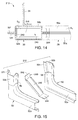
FIG. 4 is a side view of a front end of the vehicle in accordance with a first embodiment;
FIG. 5 is a perspective view of the front end of the vehicle with fenders removed showing structural features of the vehicle including an A-pillar and a sill in accordance with the first embodiment;
FIG. 6 is another side view of the front end of the vehicle with fenders removed showing details of the A-pillar and the sill in accordance with the first embodiment;
FIG. 7 is another perspective view of the front end of the vehicle showing the A-pillar and the sill in accordance with the first embodiment;
FIG. 8 is a cross-sectional view of the A-pillar taken along the line 8-8 in FIG. 6, showing details of the A-pillar, the sill and a reinforcement member in accordance with the first embodiment;
FIG. 9 is an exploded perspective view showing a portion of an inner side panel and an outer side panel that together define the A-pillar and the sill with the reinforcement member disposed therebetween in accordance with the first embodiment;
FIG. 10 is a cross-sectional view of the A-pillar similar to FIG. 8, showing details of the A-pillar, the sill, a first reinforcement member and a second reinforcement member in accordance with a second embodiment;
FIG. 11 is an exploded perspective view showing the portion of the inner side panel and the outer side panel that define the A-pillar and the sill with the first and second reinforcement members disposed therebetween in accordance with the second embodiment;
FIG. 12 is a cross-sectional view of the A-pillar similar to FIG. 8, showing details of the A-pillar, the sill and a reinforcement member in accordance with a third embodiment;
FIG. 13 is an exploded perspective view showing a portion of the inner side panel and the outer side panel that define the A-pillar and the sill with the reinforcement member disposed therebetween in accordance with the third embodiment;
FIG. 14 is a cross-sectional view of the A-pillar similar to FIG. 8, showing details of the A-pillar, the sill and a reinforcement member in accordance with a fourth embodiment;
FIG. 15 is an exploded perspective view showing a portion of the inner side panel and the outer side panel that define the A-pillar and the sill with the reinforcement member disposed therebetween in accordance with the fourth embodiment;
FIG. 16 is a cross-sectional view of the A-pillar similar to FIG. 8, showing details of the A-pillar, the sill and a reinforcement member in accordance with a fifth embodiment; and
FIG. 17 is an exploded perspective view showing a portion of the inner side panel and the outer side panel that define the A-pillar and the sill with the reinforcement member disposed therebetween in accordance with the fifth embodiment.
DETAILED DESCRIPTION OF EMBODIMENTS
Selected embodiments will now be explained with reference to the drawings. It will be apparent to those skilled in the art from this disclosure that the following descriptions of the embodiments are provided for illustration only and not for the purpose of limiting the invention as defined by the appended claims and their equivalents.
Referring initially to FIGS. 4-7, a vehicle 10 is illustrated in accordance with various embodiments. The vehicle 10 has a body structure 12 that includes various features such as, among other things, a bumper assembly 14, fenders 16 (only one fender 16 is shown in FIG. 4), a hood 18, a front side member 20, an engine cradle 22, a dash wall 24, a hood ledge 26, a sill 28 and an A-pillar 30.
The bumper assembly 14, the fenders 16, the hood 18, the front side member 20, the engine cradle 22, the dash wall 24 and the hood ledge 26 are all conventional elements, and therefore, description of these portions of the body structure 12 is limited for the sake of brevity.
The bumper assembly 14 is attached to a front end of the front side member 20. The fenders 16 and the hood 18 are exterior panels and are not necessarily structural elements of the vehicle 10. The front side member 20 is a structural member. There are two front side members 20 (only one front side member 20 is shown) located on either side of an engine compartment area of the vehicle 10. The two front side members 20 are the same and therefore description of one applies equally to both. The front side member 20 extends rearward from the bumper assembly 14 below the dash wall 24 and under the floor (not shown) of the passenger compartment of the vehicle 10. The hood ledge 26 is a curved member that extends upward and rearward from an outboard front area of the front side member 20 to the A-pillar 30.
The engine cradle 22 supports an engine assembly 36 (see FIG. 5) and is removably fastened to an underside of each of the front side members 20 in a conventional manner. The dash wall 24 separates the engine compartment and the passenger compartment of the vehicle 10 from one another.
A description of the sill 28 and the A-pillar 30 is provided below after a brief description of a recently developed vehicle test.
The Insurance Institute for Highway Safety (IIHS) has developed various tests where vehicles are provided with forward velocity VF and impacted against fixed, rigid barriers, like the rigid barrier B depicted in FIGS. 1-3. In the IIHS offset tests, the conventional vehicle C is aimed at the rigid barrier B such that approximately 25 percent of the front of the conventional vehicle C impacts the rigid barrier B. In other words, as indicated in FIGS. 1-3, only a front corner of the conventional vehicle C impacts the rigid barrier B. This IIHS test is also known as a narrow offset, or small overlap test. In such tests, a front bumper assembly of the conventional vehicle C is either not impacted, or undergoes only limited contact with the rigid barrier B during the impact event. When the vehicle C is provided with velocity and impacts the rigid barrier B, the rapid deceleration of the vehicle C transforms the kinetic energy associated with the mass and velocity of the vehicle C into deformation of the vehicle C and counter movement of the vehicle C. During the small offset test, the kinetic energy of the vehicle C is partially deflected by structures of the vehicle, absorbed by structures of the vehicle, and partially transformed into, for instance further motion and/or deformation of portions of the vehicle C. Therefore, structures at the front of the conventional vehicle C that impact the rigid barrier B absorb at least some of the impacting force that results from the impact event. For example, a majority of the impacting force is absorbed by the A-pillar and transferred to non-impacted structures of the vehicle C, such as cross members within the vehicle C.
The small overlap test is represented schematically in FIGS. 1-3. During the impact event, a variety of structures undergo deformation. This deformation is not explicitly depicted in FIGS. 2 and 3 with any degree of accuracy because such deformation varies from conventional vehicle to conventional vehicle, depending upon the overall design of the front structure of the conventional vehicle C. Instead, in FIG. 3, the conventional vehicle C is depicted with a generic degree of deformation as a result of the impact event. During the impact event with the rigid barrier B, a portion of the kinetic energy of the vehicle C is partially absorbed by deformation of structures of the vehicle C and another portion of the kinetic energy of the vehicle C is transformed into rotational or lateral movement of the conventional vehicle C such that it swings laterally away from the rigid barrier B, as indicated in FIG. 3.
As is indicated in FIG. 3, an area A where the sill and A-pillar of the vehicle C area may lie along a path coinciding with the rigid barrier B. Therefore, the area A of the vehicle C may absorb at least a portion of the kinetic energy associated with the velocity of the vehicle C.
The vehicle 10 of the various embodiments described below, includes a reinforcement member 40 shown in FIGS. 8 and 9 (described below) that strengthens the area at an intersection of the sill 28 and the A-pillar 30.
A description of the sill 28 and the A-pillar 30 is now provided with specific reference to FIGS. 8 and 9. In the depicted embodiment, the body structure 12 includes an inner side panel 50 and an outer side panel 52. The inner side panel 50 is formed, molded, cut and/or stamped using a plurality sheet metal panels that are welded or otherwise fixed together, to define various inboard shapes and surfaces of the vehicle 10. Similarly, the outer side panel 52 is formed, molded, cut and/or stamped from a plurality of single sheet metal panels that are welded or otherwise fixed to each other to define outboard shapes and surfaces of the vehicle 10. Various portions of the inner side panel 50 and outer side panel 52 together define a roof rail 54 (FIG. 7), a B-pillar 56 (FIG. 7), a C-pillar (not shown), the sill 28 and the A-pillar 30.
Hence, the sill 28 and A-pillar 30 (as well as the roof rail 54, the B-pillar 56 and the C-pillar) are each constructed from a plurality of separate panels welded or otherwise rigidly fixed to one another. However, it should be understood from the drawings and the description herein that each of the inner side panel 50 and the outer side panel 52 can each be made of a single sheet metal plate, cut and pressed into the depicted overall shape. In other words, the inner side panel 50 and the outer side panel 52 can each be a single, unitary, monolithic element. In FIG. 6, a seam 58 is depicted showing a seam between the sill 28 and the A-pillar 30. It should be understood from the drawings and the description herein that the seam 58 between the sill 28 and the A-pillar 30 can be located at any of a variety of locations. In the depicted embodiments, the seam 58 is an overlapping of two sheet metal portions, welded together. The seam 58 located above the sill 28 near the bottom of the A-pillar 30.
The area where the sill 28 and the A-pillar 30 join together is an intersection that defines a front lower corner of a door opening of the body structure 12. In the vicinity of this intersection, the sill 28 extends in a generally horizontal direction and the A-pillar 30 extends in a generally vertical direction. Therefore the intersection between the sill 28 and the A-pillar 30 substantially defines a right angle (plus or minus a couple of degrees) in the overall construction of the body structure 12.
Since the inner side panel 50 can alternatively be made of a plurality of smaller panels fitted together, the portion of the inner side panel 50 that corresponds to the sill 28 is hereinafter referred to as an inner sill panel 50 a. The inner sill panel 50 a has an upper flange 50 c and a lower flange 50 d. Similarly, the portion of the inner side panel 50 that corresponds to the A-pillar 30 is hereinafter referred to an inner A-pillar panel 50 b. The inner A-pillar panel 50 b has a rearward flange 50 e and a forward flange 50 f.
As well, the portion of the outer side panel 52 that corresponds to the sill 28 is hereinafter referred to as an outer sill panel 52 a. The outer sill panel 52 a has an upper flange 52 c and a lower flange 52 d. Similarly, the portion of the outer side panel 52 that corresponds to the A-pillar 30 is hereinafter referred to an outer A-pillar panel 52 b. The outer A-pillar panel 52 b has a rearward flange 52 e and a forward flange 52 f.
Hence, the sill 28 includes the inner sill panel 50 a and the outer sill panel 52 a fixedly attached to one another. For instance, the upper flange 50 c is welded to the upper flange 52 c and the lower flange 50 d can be welded to the lower flange 52 d. The inner sill panel 50 a has an inner sill outboard surface 60 and the outer sill panel 52 a has an outer sill inboard surface 62. The inner and outer sill panels 50 a and 52 a define an internal sill space S1 between the inner sill outboard surface 60 and the outer sill inboard surface 62.
Similarly, the A-pillar 30 includes the inner A-pillar panel 50 b and the outer A-pillar panel 52 b that are fixedly attached to one another. For instance, the rearward flange 50 e can be welded to the rearward flange 52 e and the forward flange 50 f is welded to the forward flange 52 f. The inner A-pillar panel 50 b has an inner A-pillar outboard surface 64. The outer A-pillar panel 52 b has an outer A-pillar inboard surface 66. The inner and outer A-pillar panels 50 b and 52 b are rigidly connected together to define an internal A-pillar space S2 between the inner A-pillar outboard surface 64 and the outer A-pillar inboard surface 66. The A-pillar 28 is rigidly connected to the sill 30 with the internal sill space S1 and the internal A-pillar S2 space being connected and/or open to one another.
The reinforcement member 40 is a contoured panel shaped to include a forward end 70, a rearward end 72 and a main bracing part 74 extending therebetween. The forward end 70 basically defines a flange that is inserted between the forward flange 50 f of the inner A-pillar panel 50 b and the forward flange 52 f of the outer A-pillar panel 52 b. The forward flange 50 f, the forward flange 52 f and the forward end 70 of the reinforcement member 40 are rigidly fixed to one another (for example, welded together), as indicated in FIG. 8, thereby defining a front attachment point.
The rearward end 72 includes an upper end 72 a and a lower end 72 b. The rearward end 72 of the reinforcement member 40 basically defines a flange that extends from the upper end 72 a to the lower end 72 b. The rearward end 72 is rigidly fixed to both the outer sill inboard surface 62 and the outer A-pillar inboard surface 66 by, for example, fasteners and/or welding. More specifically, the upper end 72 a is fixedly attached to the outer A-pillar inboard surface 66 of the outer A-pillar panel 52 b and the lower end 72 b is fixedly attached to the outer sill inboard surface 62 of the outer sill panel 52 a. The contact area between the flange defined by the rearward end 72 of the reinforcement member 40, the outer sill inboard surface 62, and the outer A-pillar inboard surface 66 define a rear attachment point that is laterally offset from the front attachment point.
The main bracing part 74 has a contoured shape and extends diagonally between the front and rear attachment points within both the internal sill space S1 and the internal A-pillar space S2 with respect to a vehicle longitudinal direction L.
As shown in FIG. 8, the reinforcement member 40 is therefore located within both the internal sill space S1 and the internal A-pillar space S2. More specifically, a portion of the reinforcement member 40 extends into the internal sill space S1 and a portion of the reinforcement member 40 extends into the internal A-pillar space S2.
The main bracing part 74 is inclined relative to the vehicle longitudinal direction L by an angle α1 of at least 25 degrees, measured at an upper end of the reinforcement member 40, as indicated in FIG. 8. However, the angle α1 can be between 15 and 60 degrees. Further, main bracing part 74 can be contoured such that the angle α1 measured at the top of the main bracing part 74 can differ from an angle α2 measured at the bottom of the main bracing part 74. In the depicted embodiment, the angle α1 is greater than the angle α2.
As is shown in FIG. 9, the distance between the upper end 72 a of the rearward end 72 of the main bracing part 74 and the forward end 70 is less than the distance between the lower end 72 b of the rearward end 72 of the main bracing part 74 and the forward end 70. Consequently the upper end 72 a of the main bracing part 74 is dimensioned to fit within the A-pillar 30, whereas the lower end 72 b of the main bracing part 74 is dimensioned to extend within the sill 28 under the vehicle door opening, with the rear attachment point of the reinforcement member being located under the vehicle door opening of the body structure 12. More specifically, the rear attachment point of the reinforcement member 40 is located adjacent to a forward end of the vehicle door opening.
As is shown in FIG. 8, the upper flange 50 c and the upper flange 52 c are welded to one another defining a connection area therebetween. The upper flange 50 c and the upper flange 52 c (and the connection area) extend in the vehicle longitudinal direction L. The rearward end 72 of the reinforcement member 40, which defines the rear attachment point of the reinforcement member 40 to the outer sill inboard surface 62, is located outboard of the connection area defined by the upper flange 50 c and the upper flange 52 c.
When installed within the internal sill space S1 and the internal A-pillar space S2, the reinforcement member 40 reinforces the intersection between the sill 28 and the A-pillar 30. During the small overlap test described with respect to FIG. 1-3, the addition of the reinforcement member 40 enables transfer of kinetic energy from the impact event, from the A-pillar 30 to the sill 28 and the dash wall 24, as well as other elements of the body structure 12, such that there can be a reduction of the overall deformation experienced by the A-pillar 30 during the impact event of the small overlap test.
Second Embodiment
Referring now to FIGS. 10 and 11, the body structure 12 in accordance with a second embodiment will now be explained. In view of the similarity between the first and second embodiments, the parts of the second embodiment that are identical to the parts of the first embodiment will be given the same reference numerals as the parts of the first embodiment. Moreover, the descriptions of the parts of the second embodiment that are identical to the parts of the first embodiment may be omitted for the sake of brevity.
The body structure 12 of the second embodiment includes all of the features of the first embodiment, such as the structures that define the sill 28, the A-pillar 30 and the reinforcement member 40. However, in the second embodiment, a second reinforcement member 80 is also included. The second reinforcement member 80 has a first end 82 fixedly attached to the main bracing part 74 of the reinforcement member 40 and a second end 84 fixedly attached to the inner sill outboard surface 60 of the inner sill panel 50 a and the inner A-pillar outboard surface 64.
The second reinforcement member 80 is a contoured panel that includes a main bracing part 80 a that extends between the first end 82 and the second end 84. The main bracing part 80 a is angularly offset from the inner A-pillar outboard surface 64 and the main bracing part 74 of the reinforcement member 40. More specifically, the main bracing part 80 a extends diagonally away from the main bracing part 74. More specifically, the main bracing part 80 a and the main bracing part 74 define an angle that is less than 90 degrees but is close to being perpendicular.
The reinforcement member 80 has approximately the same overall height as the reinforcement member 40. The first end 82 is fixed along its entire height to the main bracing part 74 of the reinforcement member 40. The second end 84 is contoured to follow and lie against the shape of a rearward end of the inner A-pillar outboard surface 64 of the inner A-pillar panel 50 b, and shaped to follow and lie against the inner sill outboard surface 60 of the inner sill panel 50 a.
As shown in FIG. 10, the second reinforcement member 80 is therefore located within both the internal sill space S1 and the internal A-pillar space S2. More specifically, a portion of the second reinforcement member 80 extends into the internal sill space S1 and a portion of the second reinforcement member 80 extends into the internal A-pillar space S2. The second reinforcement member 80 is provided to reinforce the reinforcement member 40 to increase cross vehicle kinetic energy transfer during an impact event.
Third Embodiment
Referring now to FIGS. 12 and 13, a body structure 112 in accordance with a third embodiment will now be explained. In view of the similarity between the first and third embodiments, the parts of the third embodiment that are identical to the parts of the first embodiment will be given the same reference numerals as the parts of the first embodiment. Moreover, the descriptions of the parts of the third embodiment that are identical to the parts of the first embodiment may be omitted for the sake of brevity.
The body structure 112 of the third embodiment includes all of the features of the first embodiment, such as the structures that define the sill 28 and the A-pillar 30. However, in the third embodiment, the reinforcement member 40 has been replaced with a reinforcement member 140. Further, the forward flange 50 f of the inner A-pillar panel 50 b is directly welded to the forward flange 52 f of the outer A-pillar panel 52 b.
The reinforcement member 140 includes a vertical section 142, a horizontal section 144 and a main bracing part 146. The vertical section 142 has a lower end 142 a and an upper end 142 b. The horizontal section 144 has a forward end 144 a and a rearward end 144 b. The forward end 144 a of the horizontal section 144 is rigidly fixed to the lower end 142 a of the vertical section 142. The horizontal section 144 and the vertical section 142 can be separate metal plates welded together, or can be made from a single metal plate material, bent such that the horizontal section 144 and the vertical section 142 define a right angle therebetween.
In the depicted embodiment, the main bracing part 146 has a cylindrical shape with a forward end 146 a and a rearward end 146 b. The forward end 146 a of the main bracing part 146 is fixedly attached to the upper end 142 b of the vertical section 142 by, for example, welding. The rearward end 146 b of the main bracing part 146 is fixedly attached to the rearward end 144 b of the horizontal section 144 by, for example, welding.
The horizontal section 144 is fixedly attached to upwardly facing surfaces of the inner sill panel 50 a and the outer sill panel 52 a. The horizontal section 144 can be mechanically fastened or welded to the inner sill panel 50 a and the outer sill panel 52 a. The vertical section 142 is fixedly attached to rearwardly facing surfaces of the inner A-pillar panel 50 b and the outer A-pillar panel 52 b. The vertical section 142 can mechanically fastened or welded to the inner A-pillar panel 50 b and the outer A-pillar panel 52 b.
Structurally, the forward end 146 a of the main bracing part 146 and the upper end 142 b of the vertical section 142 define the front attachment point between the reinforcement member 140 and the A-pillar 30. Similarly, the rearward end 146 b of the main bracing part 146 and the rearward end 144 b of the horizontal section 144 define the rear attachment point between the reinforcement member 140 and the sill 28. As is shown in FIG. 13, the front attachment point of the reinforcement member 140 (the main bracing part 146) is located vertically higher than the rear attachment point of the reinforcement member 140 (the main bracing part 146).
As shown in FIG. 12, the reinforcement member 140 is therefore located within both the internal sill space S1 and the internal A-pillar space S2. More specifically, a portion of the reinforcement member 140 extends into the internal sill space S1 and a portion of the reinforcement member 140 extends into the internal A-pillar space S2.
Fourth Embodiment
Referring now to FIGS. 14 and 15, a body structure 212 in accordance with a fourth embodiment will now be explained. In view of the similarity between the first and fourth embodiments, the parts of the fourth embodiment that are identical to the parts of the first embodiment will be given the same reference numerals as the parts of the first embodiment. Moreover, the descriptions of the parts of the fourth embodiment that are identical to the parts of the first embodiment may be omitted for the sake of brevity.
The body structure 212 of the fourth embodiment includes all of the features of the first embodiment, such as the structures that define the sill 28 and the A-pillar 30. However, in the fourth embodiment, the reinforcement member 40 has been replaced with a reinforcement member 240. Further, the forward flange 50 f of the inner A-pillar panel 50 b is directly welded to the forward flange 52 f of the outer A-pillar panel 52 b.
The reinforcement member 240 includes a vertical section 242, a horizontal section 244 and a main bracing part 246. The vertical section 242, the horizontal section 244 and the main bracing part 246 are formed from a single piece of sheet metal. More specifically, the vertical section 242, the horizontal section 244 and the main bracing part 246 are formed from a single piece of sheet metal, and therefore are formed as a single monolithic unitary member.
The horizontal section 244 is fixedly attached to upwardly facing surfaces of the inner sill panel 50 a and the outer sill panel 52 a. The horizontal section 244 can be mechanically fastened or welded to the inner sill panel 50 a and the outer sill panel 52 a. The vertical section 242 is fixedly attached to rearwardly facing surfaces of the inner A-pillar panel 50 b and the outer A-pillar panel 52 b. The vertical section 242 can be mechanically fastened or welded to the inner A-pillar panel 50 b and the outer A-pillar panel 52 b. The attachment between the vertical section 242 and the A-pillar 30 defines a front attachment point. The attachment between the horizontal section 244 and the sill 28 basically defines a rear attachment point.
In the depicted embodiment, the main bracing part 246 is basically a flat panel section that extends from the vertical section 242 to the horizontal section 244. Thus, the main bracing part 246 (the flat panel section) of the reinforcing member 240 extends from the front attachment point to the rear attachment point.
As shown in FIG. 14, the reinforcement member 240 is therefore located within both the internal sill space S1 and the internal A-pillar space S2. More specifically, a portion of the reinforcement member 240 extends into the internal sill space S1 and a portion of the reinforcement member 240 extends into the internal A-pillar space S2.
Fifth Embodiment
Referring now to FIGS. 16 and 17, a body structure 312 in accordance with a fifth embodiment will now be explained. In view of the similarity between the first and fifth embodiments, the parts of the fifth embodiment that are identical to the parts of the first embodiment will be given the same reference numerals as the parts of the first embodiment. Moreover, the descriptions of the parts of the fifth embodiment that are identical to the parts of the first embodiment may be omitted for the sake of brevity.
The body structure 312 of the fifth embodiment includes all of the features of the first embodiment, such as the structures that define the sill 28 and the A-pillar 30. However, in the fourth embodiment, the reinforcement member 40 has been replaced with a reinforcement member 340.
The reinforcement member 340 has many of the features of the reinforcement member 40 of the first embodiment, but includes more attachment locations and is longer in the vehicle longitudinal direction than the reinforcement member 40. Specifically, the reinforcement member 340 includes a forward end 370, rearward end 372 and a main bracing part 374. The forward end 370 defines a flange that extends downward and joins with a lower flange 370 a. The forward end 370 is welded to and between the forward flange 50 f of the inner A-pillar panel 50 b and the forward flange 52 f of the outer A-pillar panel 52 b. Further, the lower flange 370 a is welded to and between the lower flange 50 d of the inner sill panel 50 a and the lower flange 52 d of the outer sill panel 50 b.
The rearward end 372 of the reinforcement member 340 defines an upper flange that extends forward to a rearward flange 372 a. The rearward end 372 and the rearward flange 372 a are welded to and between the upper flange 50 c of the inner sill panel 50 a, the rearward flange 50 e of the inner A-pillar panel 50 b, and the upper flange 52 c of the outer sill panel 52 a and the rearward flange 52 e of the outer A-pillar panel 52 b, respectively.
The main bracing part 374 includes an upper section 374 a and a rear section 374 b. The upper section 374 a defines an inclined angle α3 that is similar to the angle α1 of the first embodiment. The rear section 374 b includes a plurality of contoured surfaces that serve to rigidify the intersection between the sill 18 and the A-pillar 30.
As shown in FIG. 16, the reinforcement member 340 is therefore located within both the internal sill space S1 and the internal A-pillar space S2. More specifically, a portion of the reinforcement member 340 extends into the internal sill space S1 and a portion of the reinforcement member 340 extends into the internal A-pillar space S2.
The vehicle 10 includes a variety of conventional components that are well known in the art. Since these components are well known in the art, these structures will not be discussed or illustrated in detail herein. Rather, it will be apparent to those skilled in the art from this disclosure that the components can be any type of structure and/or programming that can be used to carry out the present invention.
GENERAL INTERPRETATION OF TERMS
In understanding the scope of the present invention, the term “comprising” and its derivatives, as used herein, are intended to be open ended terms that specify the presence of the stated features, elements, components, groups, integers, and/or steps, but do not exclude the presence of other unstated features, elements, components, groups, integers and/or steps. The foregoing also applies to words having similar meanings such as the terms, “including”, “having” and their derivatives. Also, the terms “part,” “section,” “portion,” “member” or “element” when used in the singular can have the dual meaning of a single part or a plurality of parts. Also as used herein to describe the above embodiments, the following directional terms “forward”, “rearward”, “above”, “downward”, “vertical”, “horizontal”, “below” and “transverse” as well as any other similar directional terms refer to those directions of a vehicle equipped with the vehicle side body structure. Accordingly, these terms, as utilized to describe the present invention should be interpreted relative to a vehicle equipped with the vehicle side body structure.
The terms of degree such as “substantially”, “about” and “approximately” as used herein mean a reasonable amount of deviation of the modified term such that the end result is not significantly changed.
While only selected embodiments have been chosen to illustrate the present invention, it will be apparent to those skilled in the art from this disclosure that various changes and modifications can be made herein without departing from the scope of the invention as defined in the appended claims. For example, the size, shape, location or orientation of the various components can be changed as needed and/or desired. Components that are shown directly connected or contacting each other can have intermediate structures disposed between them. The functions of one element can be performed by two, and vice versa. The structures and functions of one embodiment can be adopted in another embodiment. It is not necessary for all advantages to be present in a particular embodiment at the same time. Every feature which is unique from the prior art, alone or in combination with other features, also should be considered a separate description of further inventions by the applicant, including the structural and/or functional concepts embodied by such features. Thus, the foregoing descriptions of the embodiments according to the present invention are provided for illustration only, and not for the purpose of limiting the invention as defined by the appended claims and their equivalents.

Claims (20)

What is claimed is:
1. A vehicle side body structure comprising:
a sill including an inner sill panel having an inner sill outboard surface and an outer sill panel having an outer sill inboard surface, the inner and outer sill panels being rigidly connected together to define an internal sill space between the inner sill outboard surface and the outer sill inboard surface;
an A-pillar including an inner A-pillar panel having an inner A-pillar outboard surface and an outer A-pillar panel having an outer A-pillar inboard surface, the inner and outer A-pillar panels being rigidly connected together to define an internal A-pillar space between the inner A-pillar outboard surface and the outer A-pillar inboard surface, the A-pillar being rigidly connected to the sill with the internal sill space and the internal A-pillar space being connected; and
a reinforcement member located within both the internal sill space and the internal A-pillar space, the reinforcement member having a forward end fixedly attached to at least one of the sill and the A-pillar at a front attachment point and a rearward end fixedly attached to at least one of the sill and the A-pillar at a rear attachment point that is laterally offset from the front attachment point, the reinforcement member includes a main bracing part extending diagonally between the front and rear attachment points within both the internal sill space and the internal A-pillar space with respect to a vehicle longitudinal direction, with the main bracing part of the reinforcing member extending in an outboard direction from the front attachment point to the rear attachment point.
2. The vehicle side body structure according to claim 1, wherein
the main bracing part is laterally inclined relative to the vehicle longitudinal direction by an angle of at least 25 degrees.
3. The vehicle side body structure according to claim 2, wherein
the angle is 45 degrees.
4. The vehicle side body structure according to claim 1, wherein
the sill extends under a vehicle door opening with the rear attachment point of the reinforcement member being located under the vehicle door opening.
5. The vehicle side body structure according to claim 1, wherein
the sill extends under a vehicle door opening with the rear attachment point of the reinforcement member being located adjacent to a forward end of the vehicle door opening.
6. The vehicle side body structure according to claim 1, wherein
the inner A-pillar panel, the outer A-pillar panel and the reinforcement member are fixedly attached to one another at the forward end of the reinforcement member.
7. The vehicle side body structure according to claim 1, further comprising
a second reinforcement member having a first end fixedly attached to the main bracing part of the reinforcement member and a second end fixedly attached to the inner sill outboard surface of the inner sill panel.
8. The vehicle side body structure according to claim 1, wherein
the front attachment point is located vertically higher than the rear attachment point.
9. The vehicle side body structure according to claim 1, wherein
an upper edge of the main bracing part is vertically inclined relative to the vehicle longitudinal direction.
10. A vehicle side body structure comprising:
a sill including an inner sill panel having an inner sill outboard surface and an outer sill panel having an outer sill inboard surface, the inner and outer sill panels being rigidly connected together to define an internal sill space between the inner sill outboard surface and the outer sill inboard surface;
an A-pillar including an inner A-pillar panel having an inner A-pillar outboard surface and an outer A-pillar panel having an outer A-pillar inboard surface, the inner and outer A-pillar panels being rigidly connected together to define an internal A-pillar space between the inner A-pillar outboard surface and the outer A-pillar inboard surface, the A-pillar being rigidly connected to the sill with the internal sill space and the internal A-pillar space being connected; and
a reinforcement member located within both the internal sill space and the internal A-pillar space, the reinforcement member having a forward end fixedly attached to at least one of the sill and the A-pillar at a front attachment point and a rearward end fixedly attached to at least one of the sill and the A-pillar at a rear attachment point that is laterally offset from the front attachment point, the reinforcement member includes a main bracing part extending diagonally between the front and rear attachment points within both the internal sill space and the internal A-pillar space with respect to a vehicle longitudinal direction, the forward end of the reinforcement member includes an upper section and a lower section,
the inner A-pillar panel, the outer A-pillar panel and the upper section of the forward end of the reinforcement member being fixedly attached to one another, and
a forward part of the inner sill panel, a forward part of the outer sill panel and the lower section of the forward end of the reinforcement member being fixedly attached to one another.
11. The vehicle side body structure according to claim 10, wherein
the sill extends under a vehicle door opening with the rear attachment point of the reinforcement member being located under the vehicle door opening.
12. The vehicle side body structure according to claim 10, wherein
the inner sill panel and the outer sill panel are fixedly attached to one another defining a connection area that extends in the vehicle longitudinal direction and the rear attachment point of the reinforcement member is located laterally outboard of the connection area.
13. The vehicle side body structure according to claim 10, further comprising
a second reinforcement member having a first end fixedly attached to the main bracing part of the reinforcement member and a second end fixedly attached to the inner sill outboard surface of the inner sill panel.
14. The vehicle side body structure according to claim 10, wherein
the main bracing part of the reinforcement member includes a substantially flat panel section that extends from the front attachment point to the rear attachment point.
15. A vehicle side body structure comprising
a sill including an inner sill panel having an inner sill outboard surface and an outer sill panel having an outer sill inboard surface, the inner and outer sill panels being rigidly connected together to define an internal sill space between the inner sill outboard surface and the outer sill inboard surface;
an A-pillar including an inner A-pillar panel having an inner A-pillar outboard surface and an outer A-pillar panel having an outer A-pillar inboard surface, the inner and outer A-pillar panels being rigidly connected together to define an internal A-pillar space between the inner A-pillar outboard surface and the outer A-pillar inboard surface, the A-pillar being rigidly connected to the sill with the internal sill space and the internal A-pillar space being connected; and
a reinforcement member located within both the internal sill space and the internal A-pillar space, the reinforcement member having a forward end fixedly attached to at least one of the sill and the A-pillar at a front attachment point and a rearward end fixedly attached to at least one of the sill and the A-pillar at a rear attachment point that is laterally offset from the front attachment point, the reinforcement member includes a main bracing part extending diagonally between the front and rear attachment points within both the internal sill space and the internal A-pillar space with respect to a vehicle longitudinal direction,
the inner sill panel and the outer sill panel are fixedly attached to one another defining a connection area that extends in the vehicle longitudinal direction and the rear attachment point of the reinforcement member is located laterally outboard of the connection area.
16. The vehicle side body structure according to claim 15, wherein
the sill extends under a vehicle door opening with the rear attachment point of the reinforcement member being located under the vehicle door opening.
17. The vehicle side body structure according to claim 15, further comprising
a second reinforcement member having a first end fixedly attached to the main bracing part of the reinforcement member and a second end fixedly attached to the inner sill outboard surface of the inner sill panel.
18. The vehicle side body structure according to claim 15, wherein
the main bracing part of the reinforcement member includes a substantially flat panel section that extends from the front attachment point to the rear attachment point.
19. A vehicle side body structure comprising:
a sill including an inner sill panel having an inner sill outboard surface and an outer sill panel having an outer sill inboard surface, the inner and outer sill panels being rigidly connected together to define an internal sill space between the inner sill outboard surface and the outer sill inboard surface;
an A-pillar including an inner A-pillar panel having an inner A-pillar outboard surface and an outer A-pillar panel having an outer A-pillar inboard surface, the inner and outer A-pillar panels being rigidly connected together to define an internal A-pillar space between the inner A-pillar outboard surface and the outer A-pillar inboard surface, the A-pillar being rigidly connected to the sill with the internal sill space and the internal A-pillar space being connected; and
a reinforcement member located within both the internal sill space and the internal A-pillar space, the reinforcement member having a forward end fixedly attached to at least one of the sill and the A-pillar at a front attachment point and a rearward end fixedly attached to at least one of the sill and the A-pillar at a rear attachment point that is laterally offset from the front attachment point, the reinforcement member includes a main bracing part extending diagonally between the front and rear attachment points within both the internal sill space and the internal A-pillar space with respect to a vehicle longitudinal direction, and the main bracing part of the reinforcement member includes a flat panel section that extends from the front attachment point to the rear attachment point.
20. A vehicle side body structure comprising
a sill including an inner sill panel having an inner sill outboard surface and an outer sill panel having an outer sill inboard surface, the inner and outer sill panels being rigidly connected together to define an internal sill space between the inner sill outboard surface and the outer sill inboard surface;
an A-pillar including an inner A-pillar panel having an inner A-pillar outboard surface and an outer A-pillar panel having an outer A-pillar inboard surface, the inner and outer A-pillar panels being rigidly connected together to define an internal A-pillar space between the inner A-pillar outboard surface and the outer A-pillar inboard surface, the A-pillar being rigidly connected to the sill with the internal sill space and the internal A-pillar space being connected;
a reinforcement member located within both the internal sill space and the internal A-pillar space, the reinforcement member having a forward end fixedly attached to at least one of the sill and the A-pillar at a front attachment point and a rearward end fixedly attached to at least one of the sill and the A-pillar at a rear attachment point that is laterally offset from the front attachment point, the reinforcement member includes a main bracing part extending diagonally between the front and rear attachment points within both the internal sill space and the internal A-pillar space with respect to a vehicle longitudinal direction; and
a second reinforcement member having a first end fixedly attached to the main bracing part of the reinforcement member and a second end fixedly attached to the inner sill outboard surface of the inner sill panel.
US13/852,717 2013-03-28 2013-03-28 Vehicle side body structure Active US8888173B2 (en)

Priority Applications (2)

Application Number Priority Date Filing Date Title
US13/852,717 US8888173B2 (en) 2013-03-28 2013-03-28 Vehicle side body structure
US14/315,027 US8960780B2 (en) 2013-03-28 2014-06-25 Vehicle side body structure

Applications Claiming Priority (1)

Application Number Priority Date Filing Date Title
US13/852,717 US8888173B2 (en) 2013-03-28 2013-03-28 Vehicle side body structure

Related Child Applications (1)

Application Number Title Priority Date Filing Date
US14/315,027 Division US8960780B2 (en) 2013-03-28 2014-06-25 Vehicle side body structure

Publications (2)

Publication Number Publication Date
US20140292031A1 US20140292031A1 (en) 2014-10-02
US8888173B2 true US8888173B2 (en) 2014-11-18

Family

ID=51620069

Family Applications (2)

Application Number Title Priority Date Filing Date
US13/852,717 Active US8888173B2 (en) 2013-03-28 2013-03-28 Vehicle side body structure
US14/315,027 Active US8960780B2 (en) 2013-03-28 2014-06-25 Vehicle side body structure

Family Applications After (1)

Application Number Title Priority Date Filing Date
US14/315,027 Active US8960780B2 (en) 2013-03-28 2014-06-25 Vehicle side body structure

Country Status (1)

Country Link
US (2) US8888173B2 (en)

Cited By (12)

* Cited by examiner, † Cited by third party
Publication number Priority date Publication date Assignee Title
US20150048654A1 (en) * 2011-12-06 2015-02-19 Daimler Ag Body Component
US9187135B1 (en) 2015-01-09 2015-11-17 Nissan North America, Inc. Vehicle body structure
US9248862B1 (en) 2015-01-09 2016-02-02 Nissan North America, Inc. Vehicle body structure
US20160194034A1 (en) * 2013-09-03 2016-07-07 Honda Motor Co., Ltd. Vehicle body structure
US20160325697A1 (en) * 2015-05-08 2016-11-10 GM Global Technology Operations LLC Motor vehicle body with filler piece
US9988087B2 (en) * 2013-03-26 2018-06-05 Toyota Jidosha Kabushiki Kaisha Vehicle body side structure of automobile
US10023238B2 (en) * 2014-02-04 2018-07-17 Nippon Steel & Sumitomo Metal Corporation Skeletal component for automobile and front pillar lower including the same
US10053152B2 (en) * 2015-08-20 2018-08-21 Dr. Ing. H.C. F. Porsche Aktiengesellschaft Sill for a vehicle
CN109421817A (en) * 2017-08-23 2019-03-05 马自达汽车株式会社 Body Structure
US10407104B2 (en) * 2016-02-17 2019-09-10 Hyundai Motor Company Integral type hot-stamping vehicle body structure and vehicle applying the same
US20210163073A1 (en) * 2018-04-16 2021-06-03 Tesseract Structural Innovations, Inc. Uniform deceleration unit
US11097782B2 (en) 2014-11-24 2021-08-24 Tesseract Structural Innovations, Inc. Sill beam uniform deceleration unit

Families Citing this family (16)

* Cited by examiner, † Cited by third party
Publication number Priority date Publication date Assignee Title
US9766355B2 (en) * 2013-05-09 2017-09-19 Robert H. Brune Use of vector rotational measurements and vector pressure gradient measurements to enhance spatial sampling of dual-sensor water bottom seismic data
JP6176227B2 (en) * 2014-12-11 2017-08-09 マツダ株式会社 Front body structure of the vehicle
US9751567B2 (en) * 2015-12-07 2017-09-05 GM Global Technology Operations LLC Rail assembly for controlled lateral deformation
US9884648B1 (en) 2016-10-31 2018-02-06 Nissan North America, Inc. Vehicle structure
US10029732B2 (en) 2016-10-31 2018-07-24 Nissan North America, Inc. Vehicle structure
US10093358B2 (en) 2016-10-31 2018-10-09 Nissan North America, Inc. Vehicle structure
US10093357B2 (en) 2016-10-31 2018-10-09 Nissan North America, Inc. Vehicle structure
US10150509B2 (en) 2016-10-31 2018-12-11 Nissan North America, Inc. Vehicle structure
US9956991B1 (en) 2016-10-31 2018-05-01 Nissan North America, Inc. Vehicle structure
US9956992B1 (en) 2016-10-31 2018-05-01 Nissan North America, Inc. Vehicle structure
US9988091B2 (en) 2016-10-31 2018-06-05 Nissan North America, Inc. Vehicle structure
US10086875B2 (en) 2016-10-31 2018-10-02 Nissan North America, Inc. Vehicle structure
KR102567277B1 (en) * 2016-12-07 2023-08-16 현대자동차주식회사 Structure of side sill for vehicle
US10513294B2 (en) * 2017-11-07 2019-12-24 Cnh Industrial America Llc Boxed plate construction frame with plates of varying thicknesses
EP3722185B1 (en) * 2019-04-11 2023-06-07 Volvo Car Corporation Lateral push element
DE102020113690B3 (en) 2020-05-20 2021-10-21 Bayerische Motoren Werke Aktiengesellschaft Body for a passenger car as well as passenger cars

Citations (21)

* Cited by examiner, † Cited by third party
Publication number Priority date Publication date Assignee Title
US4550948A (en) 1983-09-12 1985-11-05 Toyota Jidosha Kabushiki Kaisha Reinforced side door support structure
US5246264A (en) * 1991-08-02 1993-09-21 Mazda Motor Corporation Side body structure of automotive vehicle
US5370438A (en) * 1991-10-31 1994-12-06 Toyota Jidosha Kabushiki Kaisha Structural member of automobile
US5443297A (en) * 1993-01-22 1995-08-22 Toyoda Jidosha Kabushiki Kaisha Structure of side portion of vehicle body
US5586799A (en) * 1992-11-11 1996-12-24 Mazda Motor Corporation Upper body structure of a vehicle
US5653495A (en) * 1992-09-11 1997-08-05 Saab Automobile Aktiebolag Reinforced door aperture frame for reducing deformation from offset collisions
US5810428A (en) * 1994-07-15 1998-09-22 Nissan Motor Co., Ltd. Framework of vehicle body structure
US5860694A (en) * 1994-03-01 1999-01-19 Mercedes-Benz Ag Integral bodyshell structure for a motor vehicle and method of producing the bodyshell structure
US5984402A (en) * 1996-03-19 1999-11-16 Fuji Jukogyo Kabushiki Kaisha Sidebody structure of motor vehicle
US6053564A (en) * 1996-08-21 2000-04-25 Mitsubishi Jidosha Kogyo K.K. Vehicle body side sill reinforcing bulkhead
US20010020797A1 (en) * 2000-03-10 2001-09-13 Nissan Motor Co., Ltd. Body structure for vehicle
US6293617B1 (en) 1998-10-15 2001-09-25 Honda Giken Kogyo Kabushiki Kaisha Extruded material frame connection structure for vehicle
US20030102697A1 (en) * 2001-10-25 2003-06-05 Mitsubishi Jidosha Kogyo Kabushiki Kaisha Vehicle body side structure
US6698823B2 (en) * 2002-02-06 2004-03-02 Hyundai Motor Company Front pillar panel assembly structure of a vehicle
US7510234B2 (en) 2006-08-09 2009-03-31 Nissan Technical Center North America, Inc. Vehicle frame structure
FR2933059A1 (en) 2008-06-25 2010-01-01 Peugeot Citroen Automobiles Sa Metallic stiffening insert for motor vehicle body, has baseplate supporting reinforcement wall arranged on baseplate by extending near edge of baseplate along baseplate so as to define reinforcement box opened opposite to baseplate
US20100270828A1 (en) * 2009-04-23 2010-10-28 Ford Global Technologies, Llc Vehicle frame with offset load path to a hinge pillar and rocker
US20120119546A1 (en) * 2010-11-11 2012-05-17 Mazda Motor Corporation Frame structure for vehicle
US20130200650A1 (en) * 2012-02-08 2013-08-08 Mazda Motor Corporation Lower vehicle-body structure of vehicle
US8662575B2 (en) * 2009-12-22 2014-03-04 Honda Motor Co., Ltd. Vehicle chassis side structure
US8678481B2 (en) * 2009-12-22 2014-03-25 Honda Motor Co., Ltd. Structure for side portion of vehicle body

Family Cites Families (5)

* Cited by examiner, † Cited by third party
Publication number Priority date Publication date Assignee Title
JP3422574B2 (en) * 1994-08-31 2003-06-30 富士重工業株式会社 Side collision prevention structure for car bodies
US6926351B2 (en) * 2003-09-17 2005-08-09 Daimlerchrysler Corporation Convertible vehicle uni-body having and internal supplemental support structure
JP5562701B2 (en) * 2010-03-30 2014-07-30 ユニプレス株式会社 Connection structure of front pillar and side sill of automobile
JP2012111338A (en) * 2010-11-24 2012-06-14 Toyota Motor Corp Vehicle body side part structure
EP2711272B1 (en) * 2011-05-17 2015-04-22 Toyota Jidosha Kabushiki Kaisha Vehicle body framework structure

Patent Citations (24)

* Cited by examiner, † Cited by third party
Publication number Priority date Publication date Assignee Title
US4550948A (en) 1983-09-12 1985-11-05 Toyota Jidosha Kabushiki Kaisha Reinforced side door support structure
US5246264A (en) * 1991-08-02 1993-09-21 Mazda Motor Corporation Side body structure of automotive vehicle
US5370438A (en) * 1991-10-31 1994-12-06 Toyota Jidosha Kabushiki Kaisha Structural member of automobile
US5653495A (en) * 1992-09-11 1997-08-05 Saab Automobile Aktiebolag Reinforced door aperture frame for reducing deformation from offset collisions
US5586799A (en) * 1992-11-11 1996-12-24 Mazda Motor Corporation Upper body structure of a vehicle
US5443297A (en) * 1993-01-22 1995-08-22 Toyoda Jidosha Kabushiki Kaisha Structure of side portion of vehicle body
US5860694A (en) * 1994-03-01 1999-01-19 Mercedes-Benz Ag Integral bodyshell structure for a motor vehicle and method of producing the bodyshell structure
US5810428A (en) * 1994-07-15 1998-09-22 Nissan Motor Co., Ltd. Framework of vehicle body structure
US5984402A (en) * 1996-03-19 1999-11-16 Fuji Jukogyo Kabushiki Kaisha Sidebody structure of motor vehicle
US6053564A (en) * 1996-08-21 2000-04-25 Mitsubishi Jidosha Kogyo K.K. Vehicle body side sill reinforcing bulkhead
US6293617B1 (en) 1998-10-15 2001-09-25 Honda Giken Kogyo Kabushiki Kaisha Extruded material frame connection structure for vehicle
US6447052B2 (en) * 2000-03-10 2002-09-10 Nissan Motor Co., Ltd. Body structure for vehicle
US20010020797A1 (en) * 2000-03-10 2001-09-13 Nissan Motor Co., Ltd. Body structure for vehicle
US20030102697A1 (en) * 2001-10-25 2003-06-05 Mitsubishi Jidosha Kogyo Kabushiki Kaisha Vehicle body side structure
US6648404B2 (en) * 2001-10-25 2003-11-18 Mitsubishi Jidosha Kogyo Kabushiki Kaisha Vehicle body side structure
US6698823B2 (en) * 2002-02-06 2004-03-02 Hyundai Motor Company Front pillar panel assembly structure of a vehicle
US7510234B2 (en) 2006-08-09 2009-03-31 Nissan Technical Center North America, Inc. Vehicle frame structure
FR2933059A1 (en) 2008-06-25 2010-01-01 Peugeot Citroen Automobiles Sa Metallic stiffening insert for motor vehicle body, has baseplate supporting reinforcement wall arranged on baseplate by extending near edge of baseplate along baseplate so as to define reinforcement box opened opposite to baseplate
US20100270828A1 (en) * 2009-04-23 2010-10-28 Ford Global Technologies, Llc Vehicle frame with offset load path to a hinge pillar and rocker
US8662575B2 (en) * 2009-12-22 2014-03-04 Honda Motor Co., Ltd. Vehicle chassis side structure
US8678481B2 (en) * 2009-12-22 2014-03-25 Honda Motor Co., Ltd. Structure for side portion of vehicle body
US20120119546A1 (en) * 2010-11-11 2012-05-17 Mazda Motor Corporation Frame structure for vehicle
US20130200650A1 (en) * 2012-02-08 2013-08-08 Mazda Motor Corporation Lower vehicle-body structure of vehicle
US8690227B2 (en) * 2012-02-08 2014-04-08 Mazda Motor Corporation Lower vehicle-body structure of vehicle

Cited By (17)

* Cited by examiner, † Cited by third party
Publication number Priority date Publication date Assignee Title
US9162707B2 (en) * 2011-12-06 2015-10-20 Daimler Ag Body component
US20150048654A1 (en) * 2011-12-06 2015-02-19 Daimler Ag Body Component
US9988087B2 (en) * 2013-03-26 2018-06-05 Toyota Jidosha Kabushiki Kaisha Vehicle body side structure of automobile
US20160194034A1 (en) * 2013-09-03 2016-07-07 Honda Motor Co., Ltd. Vehicle body structure
US9809258B2 (en) * 2013-09-03 2017-11-07 Honda Motor Co., Ltd. Vehicle body structure
US10023238B2 (en) * 2014-02-04 2018-07-17 Nippon Steel & Sumitomo Metal Corporation Skeletal component for automobile and front pillar lower including the same
US11097782B2 (en) 2014-11-24 2021-08-24 Tesseract Structural Innovations, Inc. Sill beam uniform deceleration unit
US9187135B1 (en) 2015-01-09 2015-11-17 Nissan North America, Inc. Vehicle body structure
US9248862B1 (en) 2015-01-09 2016-02-02 Nissan North America, Inc. Vehicle body structure
US9630653B2 (en) 2015-01-09 2017-04-25 Nissan North America, Inc. Vehicle body structure
US9821855B2 (en) * 2015-05-08 2017-11-21 GM Global Technology Operations LLC Motor vehicle body with filler piece
US20160325697A1 (en) * 2015-05-08 2016-11-10 GM Global Technology Operations LLC Motor vehicle body with filler piece
US10053152B2 (en) * 2015-08-20 2018-08-21 Dr. Ing. H.C. F. Porsche Aktiengesellschaft Sill for a vehicle
US10407104B2 (en) * 2016-02-17 2019-09-10 Hyundai Motor Company Integral type hot-stamping vehicle body structure and vehicle applying the same
CN109421817A (en) * 2017-08-23 2019-03-05 马自达汽车株式会社 Body Structure
US10676134B2 (en) * 2017-08-23 2020-06-09 Mazda Motor Corporation Vehicle-body structure
US20210163073A1 (en) * 2018-04-16 2021-06-03 Tesseract Structural Innovations, Inc. Uniform deceleration unit

Also Published As

Publication number Publication date
US20140306490A1 (en) 2014-10-16
US20140292031A1 (en) 2014-10-02
US8960780B2 (en) 2015-02-24

Similar Documents

Publication Publication Date Title
US8888173B2 (en) Vehicle side body structure
US8876194B2 (en) Vehicle front body structure
US9981695B2 (en) Vehicle lower-body structure
JP4286884B2 (en) Auto body structure
US9381952B2 (en) Vehicle body bottom structure
US8585134B2 (en) Vehicle body lower structure
US5115878A (en) Hood structure for a vehicle
CN104619579B (en) Vehicle front body structure
JP6185437B2 (en) Vehicle front structure
US8967701B2 (en) Integrated shotgun rail deflector
CN107336748B (en) Side body structure of vehicle
CN112660244B (en) Offset collision-prevention vehicle body structure
US9045166B2 (en) Short offset sheet metal reinforcement to limit rotation during crash
CN108556924B (en) A post structure for improving 40% offset collision safety performance
JP2003118639A (en) Fender supporting structure
CN214138710U (en) Vehicle body side structure
US11433834B2 (en) Vehicle front end structure
CN109421821A (en) Bottom cover component including bottom cover stiffener
JP5783147B2 (en) Vehicle lower structure
US10486628B2 (en) Vehicle body structure
KR20200117277A (en) Front pillar structure for vehicle
CN214295849U (en) Mounting structure of rear anti-collision beam
JP2014091422A (en) Floor structure of motor vehicle
JP2019202637A (en) Vehicle body structure for vehicle
KR20190136787A (en) Vehicle cowl structure

Legal Events

Date Code Title Description
AS Assignment

Owner name: NISSAN NORTH AMERICA, INC., TENNESSEE

Free format text: ASSIGNMENT OF ASSIGNORS INTEREST;ASSIGNORS:NYDAM, SCOTT;AMELOOT, KENNETH;REEL/FRAME:030109/0209

Effective date: 20130328

STCF Information on status: patent grant

Free format text: PATENTED CASE

AS Assignment

Owner name: NISSAN MOTOR CO., LTD., JAPAN

Free format text: ASSIGNMENT OF ASSIGNORS INTEREST;ASSIGNOR:NISSAN NORTH AMERICA, INC.;REEL/FRAME:034936/0255

Effective date: 20150209

MAFP Maintenance fee payment

Free format text: PAYMENT OF MAINTENANCE FEE, 4TH YEAR, LARGE ENTITY (ORIGINAL EVENT CODE: M1551)

Year of fee payment: 4

MAFP Maintenance fee payment

Free format text: PAYMENT OF MAINTENANCE FEE, 8TH YEAR, LARGE ENTITY (ORIGINAL EVENT CODE: M1552); ENTITY STATUS OF PATENT OWNER: LARGE ENTITY

Year of fee payment: 8