US8888665B2 - Exercise device - Google Patents
Exercise device Download PDFInfo
- Publication number
- US8888665B2 US8888665B2 US13/802,925 US201313802925A US8888665B2 US 8888665 B2 US8888665 B2 US 8888665B2 US 201313802925 A US201313802925 A US 201313802925A US 8888665 B2 US8888665 B2 US 8888665B2
- Authority
- US
- United States
- Prior art keywords
- main body
- exercise device
- chamber
- component
- disposed
- Prior art date
- Legal status (The legal status is an assumption and is not a legal conclusion. Google has not performed a legal analysis and makes no representation as to the accuracy of the status listed.)
- Active
Links
Images


Classifications
-
- A—HUMAN NECESSITIES
- A63—SPORTS; GAMES; AMUSEMENTS
- A63B—APPARATUS FOR PHYSICAL TRAINING, GYMNASTICS, SWIMMING, CLIMBING, OR FENCING; BALL GAMES; TRAINING EQUIPMENT
- A63B21/00—Exercising apparatus for developing or strengthening the muscles or joints of the body by working against a counterforce, with or without measuring devices
- A63B21/06—User-manipulated weights
- A63B21/0618—User-manipulated weights moving in a horizontal plane without substantial friction, i.e. using inertial forces
-
- A—HUMAN NECESSITIES
- A63—SPORTS; GAMES; AMUSEMENTS
- A63B—APPARATUS FOR PHYSICAL TRAINING, GYMNASTICS, SWIMMING, CLIMBING, OR FENCING; BALL GAMES; TRAINING EQUIPMENT
- A63B21/00—Exercising apparatus for developing or strengthening the muscles or joints of the body by working against a counterforce, with or without measuring devices
- A63B21/06—User-manipulated weights
- A63B21/0601—Special physical structures of used masses
- A63B21/0602—Fluids, e.g. water
-
- A—HUMAN NECESSITIES
- A63—SPORTS; GAMES; AMUSEMENTS
- A63B—APPARATUS FOR PHYSICAL TRAINING, GYMNASTICS, SWIMMING, CLIMBING, OR FENCING; BALL GAMES; TRAINING EQUIPMENT
- A63B21/00—Exercising apparatus for developing or strengthening the muscles or joints of the body by working against a counterforce, with or without measuring devices
- A63B21/06—User-manipulated weights
- A63B21/0601—Special physical structures of used masses
- A63B21/0603—Fluid-like particles, e.g. gun shot or sand
-
- A—HUMAN NECESSITIES
- A63—SPORTS; GAMES; AMUSEMENTS
- A63B—APPARATUS FOR PHYSICAL TRAINING, GYMNASTICS, SWIMMING, CLIMBING, OR FENCING; BALL GAMES; TRAINING EQUIPMENT
- A63B21/00—Exercising apparatus for developing or strengthening the muscles or joints of the body by working against a counterforce, with or without measuring devices
- A63B21/06—User-manipulated weights
- A63B21/0608—Eccentric weights put into orbital motion by nutating movement of the user
-
- A—HUMAN NECESSITIES
- A63—SPORTS; GAMES; AMUSEMENTS
- A63B—APPARATUS FOR PHYSICAL TRAINING, GYMNASTICS, SWIMMING, CLIMBING, OR FENCING; BALL GAMES; TRAINING EQUIPMENT
- A63B21/00—Exercising apparatus for developing or strengthening the muscles or joints of the body by working against a counterforce, with or without measuring devices
- A63B21/06—User-manipulated weights
- A63B21/072—Dumb-bells, bar-bells or the like, e.g. weight discs having an integral peripheral handle
- A63B21/0724—Bar-bells; Hand bars
-
- A—HUMAN NECESSITIES
- A63—SPORTS; GAMES; AMUSEMENTS
- A63B—APPARATUS FOR PHYSICAL TRAINING, GYMNASTICS, SWIMMING, CLIMBING, OR FENCING; BALL GAMES; TRAINING EQUIPMENT
- A63B21/00—Exercising apparatus for developing or strengthening the muscles or joints of the body by working against a counterforce, with or without measuring devices
- A63B21/06—User-manipulated weights
- A63B21/072—Dumb-bells, bar-bells or the like, e.g. weight discs having an integral peripheral handle
- A63B21/0728—Dumb-bells, bar-bells or the like, e.g. weight discs having an integral peripheral handle with means for fixing weights on bars, i.e. fixing olympic discs or bumper plates on bar-bells or dumb-bells
-
- A—HUMAN NECESSITIES
- A63—SPORTS; GAMES; AMUSEMENTS
- A63B—APPARATUS FOR PHYSICAL TRAINING, GYMNASTICS, SWIMMING, CLIMBING, OR FENCING; BALL GAMES; TRAINING EQUIPMENT
- A63B21/00—Exercising apparatus for developing or strengthening the muscles or joints of the body by working against a counterforce, with or without measuring devices
- A63B21/06—User-manipulated weights
- A63B21/072—Dumb-bells, bar-bells or the like, e.g. weight discs having an integral peripheral handle
- A63B21/075—Dumb-bells, bar-bells or the like, e.g. weight discs having an integral peripheral handle with variable weights, e.g. weight systems with weight selecting means for bar-bells or dumb-bells
-
- A—HUMAN NECESSITIES
- A63—SPORTS; GAMES; AMUSEMENTS
- A63B—APPARATUS FOR PHYSICAL TRAINING, GYMNASTICS, SWIMMING, CLIMBING, OR FENCING; BALL GAMES; TRAINING EQUIPMENT
- A63B23/00—Exercising apparatus specially adapted for particular parts of the body
- A63B23/035—Exercising apparatus specially adapted for particular parts of the body for limbs, i.e. upper or lower limbs, e.g. simultaneously
- A63B23/03575—Apparatus used for exercising upper and lower limbs simultaneously
-
- A—HUMAN NECESSITIES
- A63—SPORTS; GAMES; AMUSEMENTS
- A63B—APPARATUS FOR PHYSICAL TRAINING, GYMNASTICS, SWIMMING, CLIMBING, OR FENCING; BALL GAMES; TRAINING EQUIPMENT
- A63B71/00—Games or sports accessories not covered in groups A63B1/00 - A63B69/00
- A63B71/06—Indicating or scoring devices for games or players, or for other sports activities
- A63B71/0619—Displays, user interfaces and indicating devices, specially adapted for sport equipment, e.g. display mounted on treadmills
- A63B2071/065—Visualisation of specific exercise parameters
- A63B2071/0652—Visualisation or indication relating to symmetrical exercise, e.g. right-left performance related to spinal column
-
- A—HUMAN NECESSITIES
- A63—SPORTS; GAMES; AMUSEMENTS
- A63B—APPARATUS FOR PHYSICAL TRAINING, GYMNASTICS, SWIMMING, CLIMBING, OR FENCING; BALL GAMES; TRAINING EQUIPMENT
- A63B71/00—Games or sports accessories not covered in groups A63B1/00 - A63B69/00
- A63B71/06—Indicating or scoring devices for games or players, or for other sports activities
- A63B71/0619—Displays, user interfaces and indicating devices, specially adapted for sport equipment, e.g. display mounted on treadmills
- A63B2071/0655—Tactile feedback
Definitions
- the invention relates to an exercise device and more particularly to an exercise device having a chamber formed therein for containing at least one displaceable component.
- Exercise devices can be an important aid to individuals seeking to maintain and improve a level of physical fitness.
- One type of exercise device is often called a slosh pipe or a slosh tube.
- the slosh pipe includes a chamber formed therein.
- a flowable material such as water or sand, for example, is disposed within the chamber.
- a person uses legs or arms, for example, to raise and lower the slosh pipe while trying to maintain the slosh pipe in a level position to militate against a flow of the flowable material within the chamber.
- the person senses a change in the distribution of the flowable material through a change in the balance of the weight of the slosh pipe. The person must adjust movement in an attempt to return the exercise devise to a level position and restore the uniform distribution of the flowable material therein.
- the slosh pipe may be employed to promote muscle coordination and overall balance of a user. Additionally, fine muscle control often needed to maintain the slosh pipe in a level position may provide targeted exercise of certain muscle groups that are not exercised or difficult to exercise employing traditional exercise devices such as free weights, dumbbells, and the like, for example.
- the slosh pipe typically only provides tactile feedback to a user. Providing feedback to the user through other senses such as the sense of sight, for example, may provide additional fitness benefits and minimize the perceived or actual difficulty of exercising with the slosh pipe.
- an exercise device including at least one displaceable component disposed therein, wherein tactile and visual feedback are provided to a user in respect of maintaining an even distribution of the at least one displaceable component while using the exercise device.
- an exercise device including at least one displaceable component disposed therein, wherein tactile and visual feedback are provided to a user in respect of maintaining an even distribution of the at least one displaceable component while using the exercise device, has surprisingly been discovered.
- an exercise device comprises: a main body including at least one chamber formed therein, at least a portion of the main body configured to be grasped by a user; and a first displaceable component disposed within the at least one chamber, wherein the first displaceable component is at least one rolling component.
- an exercise device comprises: a main body including a plurality of hubs disposed thereon and at least one chamber formed therein, at least a portion of the main body configured to be grasped by a user; and at least one containment article extending between the hubs of the main body, the at least one containment article including at least one chamber formed therein, wherein at least one displaceable component is disposed within at least one of the at least one chamber of the main body and the at least one chamber of the at least one containment article.
- an exercise device comprises: a main body including a plurality of hubs disposed thereon and at least one chamber formed therein, at least a portion of the main body configured to be grasped by a user; a first displaceable component disposed within the at least one chamber of the main body, wherein the first displaceable component is at least one of a flowable component, a slidable component, and a rolling component; and at least one containment article extending between the hubs of the main body.
- the present invention is advantageous over prior art exercise devices by providing the benefit of functional training.
- Functional training enables a body of a user to react quickly, as well as enhances the ability of the body to perform designated tasks.
- functional training provides a neurological adaptation component to a workout which is lacking in traditional machine or dumbbell training.
- the nervous system is required to adapt to new stimuli when the body adjusts quickly or reacts to an unpredictable outside influence such as the movement of the displaceable component inside the exercise device of the present invention.
- the present invention trains the user to be multifunctional, preparing the user for activities of daily life.
- FIG. 1 is a perspective view of an exercise device according to an embodiment of the invention
- FIG. 2 is an exploded perspective view of an exercise device according to another embodiment of the invention.
- FIG. 3 is a perspective view of an exercise device according to another embodiment of the invention, having a portion thereof cutaway;
- FIG. 4 is an exploded perspective view of an exercise device according to another embodiment of the invention.
- FIG. 5 is an exploded perspective view of an exercise device according to another embodiment of the invention.
- FIG. 6 is a perspective view of an exercise device according to another embodiment of the invention.
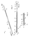
- FIG. 7 is a perspective view of an exercise device according to another embodiment of the invention.
- FIG. 8 is a cross-sectional elevational view of the exercise device illustrated in FIG. 7 taken along section line 8 - 8 ;
- FIG. 9 is an enlarged fragmentary cross-sectional view of a portion of the exercise device illustrated in FIGS. 7-8 ;
- FIG. 10 is a perspective view of an exercise device according to yet another embodiment of the invention.
- FIG. 11 is a partially exploded view of the exercise device illustrated in FIG. 10 ;
- FIG. 12 is a perspective view of an exercise device according to yet another embodiment of the invention.
- FIG. 13 is a cross-sectional elevational view of the exercise device illustrated in FIG. 12 taken along section line 12 - 12 .
- the exercise device 10 includes an elongate hollow main body 12 having end caps 14 , 16 disposed on opposing ends thereof.
- the main body 12 is formed from a substantially transparent material. It should be understood that the main body 12 may be formed from translucent materials and opaque materials.
- the main body 12 and end caps 14 , 16 form a substantially media tight chamber 18 within the main body 12 . It should be understood that the end caps 14 , 16 can include a sealing member such as an O-ring, a flat gasket, and the like, for example.
- At least one of the end caps 14 , 16 is removably disposed on the main body 12 to provide an opening into the hollow interior of the main body 12 .
- the main body 12 can be adapted to receive weight plates and the like thereon.
- a level indicator 20 is disposed within the chamber 18 .
- the level indicator 20 is an elongate spirit level, often referred to as a bubble level. Ends of the level indicator 20 are coupled to the respective end caps 14 , 16 to position the level indicator 20 substantially co-axially with the main body 12 .
- the level indicator 20 is visible through the substantially transparent main body 12 .
- the level indicator 20 can be formed from an elongate support member having a level indicator such as a spirit level attached thereto. It should also be understood that the level indicator 20 can be coupled to the main body 12 on an inner surface or an outer surface thereof.
- At least one displaceable component 22 such as a flowable component (e.g. at least one fluid or granular material), a slidable component (e.g. at least one linear slide), a rolling component (e.g. at least one generally spherical body), or any combination thereof, for example, is disposed within the chamber 18 .
- One or more displaceable components 22 fill at least a portion of the chamber 18 , wherein the displaceable component 22 can move between the inner surface of the main body 12 and an outer surface of the level indicator 20 and the ends of the main body 12 . It should be understood that a selected number or amount of the displaceable component 22 can be disposed within the chamber 18 to provide a selected total weight to the exercise device 10 .
- At least a portion of the main body 12 and/or the end caps 14 , 16 may include at least one dampening member (not shown) disposed thereon or formed therein such as a rubber mount, for example, to attenuate a noise and vibration produced when the displaceable component 22 contacts the main body 12 and/or the end caps 14 , 16 during operation.
- at least one dampening member (not shown) disposed thereon or formed therein such as a rubber mount, for example, to attenuate a noise and vibration produced when the displaceable component 22 contacts the main body 12 and/or the end caps 14 , 16 during operation.
- baffles 24 may be disposed within the chamber 18 to restrict a movement of the displaceable component 22 within the chamber 18 or dampen the movement thereof.
- the baffles 24 are disk shaped members having a central opening 26 , wherein the central opening of the disk receives the level indicator 20 to position the disk between the level indicator 20 and the inner surface of the chamber 18 to reduce an area of movement therebetween.
- the baffle 24 may include a plurality of openings 28 formed therein to allow the displaceable component 22 to move through the baffle 24 . It should be understood that other baffles 24 can be used such as a fibrous material, for example. It should also be understood that the baffles 24 can be removed from or inserted into the chamber 18 as desired to provide a desired level of resistance of the displaceable component 22 .
- one of the end caps 14 , 16 is removed from the end of the main body 12 to provide access to the chamber 18 formed therein.
- the selected number or amount of the displaceable component 22 is disposed within the chamber 18 .
- the chamber 18 is partially filled with the displaceable component 22 to allow the displaceable component 22 to freely move within the chamber 18 .
- One or more of the baffles 24 may be disposed within the chamber 18 to restrict the movement of the displaceable component 22 .
- the one of the end caps 14 , 16 is attached to the main body 12 to retain the displaceable component 22 within the chamber 18 and facilitate securing the level indicator 20 to the main body 12 .
- weight plates can be attached to the main body 12 to cooperate with the displaceable component 22 to provide a desired total weight for the exercise device 10 .
- the displaceable component 22 will move toward one of the ends of the chamber 18 creating an uneven distribution of the displaceable component 22 along a length of the exercise device 10 .
- Tactile feedback is provided to the user as the uneven distribution of the displaceable component 22 will be felt as an imbalance of the exercise device 10 .
- the exercise device 10 is positioned by the user so that the level indicator 20 can be viewed by the user while performing the exercise movement.
- the level indicator 20 provides a visual input to the user as to the level position of the exercise device 10 .
- the user employs the tactile input provided by the movement of the displaceable component 22 and the visual input provided by the level indicator 20 to coordinate body movement to maintain the exercise device 10 in a level position throughout the exercise movement.
- the baffles 24 may be employed by users that are not experienced performing exercise movements with the exercise device 10 to minimize the tactile feedback resulting from not maintaining the exercise device 10 in the level position. As a user improves an ability to maintain the level position of the exercise device 10 , fewer or no baffles 24 may be employed to maximize the tactile feedback.
- FIG. 2 shows an alternate embodiment of the exercise device 10 shown in FIG. 1 .
- Structure similar to that illustrated in FIG. 1 includes the same reference numeral and a prime (′) symbol for clarity.
- an exercise device 10 ′ is shown having an elongate hollow main body 30 including opposing ends 32 , 34 and a central portion 36 between the ends 32 , 34 .
- End caps 14 ′, 16 ′ are disposed on the respective ends 32 , 34 of the main body 30 .
- the main body 30 and the end caps 14 ′, 16 ′ form a substantially media tight chamber 18 ′ within the main body 30 .
- a diameter of the central portion 36 of the main body 30 is smaller than a diameter of the ends 32 , 34 to facilitate a user grasping the central portion 36 of the main body 30 .
- the ends 32 , 34 can be adapted to receive weight plates 38 and the like thereon. It should be understood that the weight plates 38 can be substantially secured to the ends 32 , 34 employing an interference fit or a retaining collar, as is commonly known in the art. Further, a thread can be formed in each of the ends 32 , 34 to facilitate receiving the weight plates 38 or the retaining collar.
- One or more baffles (not shown) can be disposed within the chamber 18 ′. The remaining structure and use of the exercise device 10 ′ is substantially the same as the structure and use of the exercise device 10 shown in FIG. 1 and described herein above.
- an exercise device 50 is illustrated showing another embodiment of the invention.
- the exercise device 50 includes a main body 52 including a bar 54 having opposing ends 56 , 58 .
- a pair of hollow substantially media tight chambers 60 , 62 is disposed on the ends 56 , 58 , respectively, of the bar 54 .
- the bar 54 is substantially linear. It should be understood that the bar 54 can include bends and curved portions such as an exercise bar commonly known as an E-Z curl bar, for example.
- the chambers 60 , 62 may be removably disposed on the ends 56 , 58 to allow for the use of different sized and shaped chambers 60 , 62 .
- the chambers 60 , 62 can be adapted to receive weight plates and the like thereon.
- the chambers 60 , 62 include end caps 64 , 66 , respectively, disposed on an end thereof.
- the end caps 64 , 66 are removably disposed on the chambers 60 , 62 to provide an opening into the hollow interior thereof.
- the end caps 64 , 66 facilitate forming a substantially media tight seal between the chambers 60 , 62 and the end caps 64 , 66 .
- the end caps 64 , 66 can include a sealing member such as an O-ring, a flat gasket, and the like, for example.
- Level indicators 68 are provided on an exterior surface of the bar 54 and an exterior surface of the chambers 60 , 62 . It should be understood that a single level indicator 68 can be used and attached to one of the bar 54 and the chambers 60 , 62 . Further, the level indicators 68 can be disposed in the bar 54 and the chambers 60 , 62 such as within a countersink and a cavity formed therein, for example.
- At least one displaceable component 70 such as a flowable component (e.g. at least one fluid or a granular material), a slidable component (e.g. at least one linear slide), a rolling component (e.g. at least one generally spherical body), or any combination thereof, for example, is disposed within the chambers 60 , 62 .
- One or more displaceable components 70 fill at least a portion of the chambers 60 , 62 , wherein the displaceable component 70 can move therein. It should be understood that a selected number or amount of the displaceable component 70 can be disposed within the chambers 60 , 62 to provide a selected total weight to the exercise device 50 .
- One or more baffles (not shown) can be disposed within the chamber 60 , 62 to restrict the movement of the displaceable component 70 therein.
- the remaining structure and use of the exercise device 50 is substantially the same as the structure and use of the exercise device 10 shown in FIG. 1 and described hereinabove.
- an exercise device 72 is illustrated showing another embodiment of the invention.
- the exercise device 72 includes a main body 74 including a bar 76 having opposing ends 78 , 80 .
- the bar 76 is similar in size and shape to a conventional Olympic barbell. However, it is understood that the bar 76 can have any shape and size. Further, the bar 76 can be adapted to receive a plurality of weight plates 82 and locking collars 84 as appreciated by one skilled in the art.
- a substantially media tight chamber 86 is substantially centrally formed along a longitudinal axis A-A of the bar 76 .
- the bar 76 and the chamber 86 are substantially linear. It should be understood that the bar can include bends and curved portions such as an exercise bar commonly known as an E-Z curl bar, for example.
- the bar 76 typically includes end caps 88 , 90 , respectively disposed on the opposing ends 78 , 80 .
- the end caps 88 , 90 are removably disposed on the bar 76 to provide an opening into the chamber 86 .
- the end caps 88 , 90 facilitate forming a substantially media tight seal between the bar 76 and the end caps 88 , 90 .
- end caps 88 , 90 can include a sealing member such as an O-ring, a flat gasket, and the like, for example. It is further understood that the chamber 86 can be sealed using other means. In certain embodiments, a level indicator (not shown) is coupled to an exterior surface of the bar 76 .
- At least one displaceable component 92 such as a flowable component (e.g. at least one fluid or granular material), a slidable component (e.g. at least one linear slide), a rolling component (e.g. at least one generally spherical body), or any combination thereof, for example, is disposed within the chamber 86 .
- One or more displaceable components 92 fill at least a portion of the chamber 86 , wherein the displaceable component 92 can move therein. It should be understood that a selected number or amount of the displaceable component 92 can be disposed within the chamber 86 to provide a selected total weight to the exercise device 72 .
- One or more baffles can be disposed within the chamber 86 to restrict the movement of the displaceable component 92 therein. It is also contemplated that at least a portion of the bar 76 and/or the end caps 88 , 90 may include at least one dampening member (not shown) disposed thereon or formed therein such as a rubber mount, for example, to attenuate a noise and vibration produced when the displaceable component 92 contacts the bar 76 and/or the end caps 88 , 90 during operation.
- the remaining structure and use of the exercise device 72 is substantially the same as the structure and use of the exercise device 10 shown in FIG. 1 and described herein above.
- an exercise device 100 is illustrated showing another embodiment of the invention.
- the exercise device 100 includes a main body 101 having opposing ends 102 , 104 .
- the main body 101 is a hollow tube.
- the main body 101 can have any shape and size.
- the main body 101 can be adapted to receive a plurality of weight plates (not shown) as appreciated by one skilled in the art.
- a substantially media tight chamber 106 is substantially centrally formed along a longitudinal axis B-B of the main body 101 .
- the main body 101 and the chamber 106 are substantially linear.
- the main body 101 typically includes end caps 108 , 110 or inserts disposed in/on the opposing ends 102 , 104 thereof. At least one of the end caps 108 , 110 is removably disposed in the main body 101 to facilitate forming a substantially media tight seal between the main body 101 and the at least one of the end caps 108 , 110 .
- the end caps 108 , 110 can include a sealing member such as an O-ring, a flat gasket, and the like, for example.
- each of the end caps 108 , 110 includes a main body 112 having an integral hub 114 circumferentially disposed around the main body 112 and extending radially outwardly therefrom.
- the integral hub 114 is disposed intermediate opposing ends of the respective main body 112 of each of the end caps 108 , 110 .
- the integral hubs 114 have a generally hexagonal shape.
- the integral hubs 114 can have any size and shape, as desired.
- the main body 112 (e.g. formed polyvinyl chloride) of each of the end caps 108 , 110 includes an interior portion 116 and an exterior portion 118 extending axially outwardly in generally opposing directions from the integral hub 114 .
- each of the interior portion 116 and the exterior portion 118 has a substantially cylindrical shape.
- the interior portion 116 has a diameter W 1 that is greater than a diameter W 2 of the exterior portion 118 .
- the interior portion 116 and the exterior portion 118 can have any size and shape relative to each other.
- an outer hub 120 is disposed adjacent the integral hub 114 of the main body 112 of each of the end caps 108 , 110 .
- the outer hubs 120 each include a main body 122 having an aperture 124 formed therein and a recessed portion 126 circumferentially formed adjacent the aperture 124 .
- the aperture 124 is generally circular to receive the exterior portion 118 of an associated one of the end caps 108 , 110 .
- the recessed portion 126 has a shape (e.g. generally hexagonal) to receive the integral hub 114 of one of the end caps 108 , 110 and thereby secure the outer hub 120 to the integral 114 .
- the outer hubs 120 can be bonded to the integral hubs 114 .
- the outer hubs 120 can be formed from polyurethane to optimize a bonding with the integral hubs 114 . However, other materials can be used.
- At least one of the end caps 108 , 110 includes a channel 128 formed therethrough to allow a displaceable component to pass therethrough.
- a plug 130 is removeably received in an end of the channel 128 to provide a fluid tight seal and to militate against a fluid passing through the channel 128 .
- a port 132 or purge hole is in fluid communication with the channel 128 to allow air from the chamber 106 to pass therethrough, as understood in the art.
- the exterior portions 118 of each of the end caps 108 , 110 are adapted to receive a retaining element 134 or collar.
- the exterior portions 118 are threaded to threadably engage the retaining element 134 to militate against undesired movement of the retaining element 134 relative to the end caps 108 , 110 .
- a plurality of weight plates (not shown) can be releasably disposed around the exterior portion 118 of the end caps 108 , 110 and adjacent the integral hub 114 .
- the retaining element 134 can be positioned to secure the weight plates against the integral hub 114 . It is understood when the outer hub 120 is disposed adjacent the integral hub 114 , the weight plates are disposed adjacent the outer hub 120 and secured against the outer hub 120 .
- At least one displaceable component 136 such as a flowable component (e.g. at least one fluid or granular material), a slidable component (e.g. at least one linear slide), a rolling component (e.g. at least one generally spherical body), or any combination thereof, for example, is disposed within the chamber 106 .
- a flowable component e.g. at least one fluid or granular material
- a slidable component e.g. at least one linear slide
- a rolling component e.g. at least one generally spherical body
- At least a portion of the main body 102 and/or the end caps 108 , 110 may include at least one dampening member (not shown) disposed thereon or formed therein such as a rubber mount, for example, to attenuate a noise and vibration produced when the displaceable components 136 contact the main body 102 and/or the end caps 108 , 110 during operation.
- at least one dampening member (not shown) disposed thereon or formed therein such as a rubber mount, for example, to attenuate a noise and vibration produced when the displaceable components 136 contact the main body 102 and/or the end caps 108 , 110 during operation.
- each of the end caps 108 , 110 are inserted into the opposing ends 102 , 104 of the main body 101 .
- the first end cap 108 is solid and effectively seals the first end 102 of the main body 101
- the second end cap 110 includes the channel 128 to allow the displaceable component 136 to be exchanged within the chamber 106 .
- the integral hubs 114 abut the main body 101 .
- the outer hubs 120 are disposed adjacent the integral hubs 114 and secured in position by the retaining elements 134 . It is understood that a desired number of weight plates can be positioned between the retaining elements 134 and the outer hubs 120 .
- gaskets or O-rings can be positioned between the retaining elements 134 and the outer hubs 120 to provide a friction therebetween to militate against an undesired relative rotation.
- the chamber 106 of the exercise device 100 Prior to, during, or after assembly, the chamber 106 of the exercise device 100 can be filled with the displaceable component 136 . It should be understood that a selected number or amount of the displaceable component 136 can be disposed within the chamber 106 to provide a selected total weight to the exercise device 100 .
- One or more baffles (not shown) can be disposed within the chamber 106 to restrict the movement of the displaceable component 136 therein.
- an exercise device 200 is illustrated showing another embodiment of the invention.
- the exercise device 200 includes a main body 201 having a substantially media tight chamber 202 formed therein.
- the chamber 202 is substantially centrally formed along a longitudinal axis of the main body 201 .
- the main body 201 has a generally cylindrical shape and the chamber 202 is substantially linear.
- the main body 201 can include bends and curved portions, for example.
- a plug 204 is removeably received in an opening 206 formed in the main body 201 to selectively allow a fluid to pass into/out of the chamber 202 .
- a port 208 or purge hole is in fluid communication with the chamber 202 to allow air from the chamber 202 to pass therethrough during a filling operation, as understood in the art.
- a plurality of interface elements 210 is coupled to the main body 201 to allow a user to directly and/or indirectly engage the exercise device 200 to execute a lifting and/or a lateral motion.
- each of the interface elements 210 includes a main body 212 receiving at least a portion of the main body 201 therethrough to facilitate coupling the main body 201 to the interface elements 210 .
- at least one of the interface elements 210 includes an aperture 213 formed therethrough to receive the main body 201 to slidably couple the main body 201 to the at least one of the interface elements 210 .
- the slidable engagement between the at least one of the interface elements 210 and the main body 201 allows adjustment of a spacing between the at least one of the interface elements 210 and the other of the interface elements 210 .
- a pair of the interface elements 210 is fixedly disposed adjacent opposing ends of the main body 201 and another of the interface elements 210 is slidably coupled to the main body 201 intermediate the pair of the interface elements 210 .
- each of the interface elements 210 includes a handle portion 214 and a through-hole 215 .
- the handle portions 214 provide a means for a user to grasp the interface elements 210 to lift or move the exercise device 200 . It is understood that the size, shape, and position of the handle portions 214 can be varied.
- the through-holes 215 are shown interposed between the handle portions 214 of the respective interface element 210 and the main body 201 .
- the through-holes 215 are sized to receive at least a portion of a conventional barbell 216 therethrough to couple the exercise device 200 to the barbell 216 in a manner consistent with a conventional weight plate.
- the at least one of the interface elements 210 that is slidably coupled to the main body 201 can be positioned to facilitate a secure coupling of the exercise device 200 and the barbell 216 .
- At least one displaceable component 218 such as a flowable component (e.g. at least one fluid or granular material), a slidable component (e.g. at least one linear slide), a rolling component (e.g. at least one generally spherical body), or any combination thereof, for example, is disposed within the chamber 202 .
- One or more displaceable components 218 fill at least a portion of the chamber 202 , wherein the displaceable components 218 can move therein. It should be understood that a selected number and amount of the displaceable component 218 can be disposed within the chamber 202 to provide a selected total weight to the exercise device 200 .
- baffles can be disposed within the chamber 202 to restrict the movement of the displaceable component 218 therein. It is also contemplated that at least a portion of the main body 201 may include at least one dampening member (not shown) disposed thereon or formed therein such as a rubber mount, for example, to attenuate a noise and vibration produced when the displaceable component 218 contacts portions of the main body 201 during operation.
- the exercise device 200 can be directly (e.g. via the handle portions 214 ) and/or indirectly (e.g. via the barbell 216 coupled to the exercise device 200 ) engaged by a user. Accordingly, the displaceable component 218 provides sensory feedback to the user in respect of maintaining the exercise device 200 in a substantially level position while in use.
- an exercise device 300 is illustrated showing another embodiment of the invention.
- the exercise device 300 includes a main body 301 having opposing ends 302 , 304 .
- the main body 301 is a substantially cylindrical hollow tube having a length of about forty-eight (48) inches.
- the main body 301 is a substantially cylindrical hollow tube having a length of about eighty-four (84) inches.
- the main body 301 is similar in size and shape to a conventional Olympic barbell. However, it is understood that the main body 301 can have any shape and size as desired.
- main body 301 can include additional features to enhance a grip of the user onto the exercise device 300 such as knurls 305 (shown in FIG. 7 ) formed therein, for example. Further, the main body 301 can be configured to receive a plurality of weight plates (not shown) as appreciated by one skilled in the art.
- a chamber 306 (shown in FIGS. 8-9 ) is substantially centrally formed within the main body 301 along a longitudinal axis thereof.
- the main body 301 and the chamber 306 are substantially linear.
- the main body 301 typically includes end caps 308 , 310 or inserts disposed in/on the opposing ends 302 , 304 thereof.
- the end caps 308 , 310 can be formed from any suitable material (e.g. a metal material or a non-metal material) and by any suitable process as desired.
- the end caps 308 , 310 are threadably engaged with the respective ends 302 , 304 .
- At least one of the end caps 308 , 310 is removably disposed in the main body 301 to facilitate forming a substantially media tight seal between the main body 301 and the at least one of the end caps 308 , 310 .
- the end caps 308 , 310 can include a sealing member such as an O-ring, a flat gasket, and the like, for example.
- each of the end caps 308 , 310 includes a main body 312 having a shoulder 314 circumferentially disposed around the main body 312 and extending radially outwardly therefrom.
- a pair of spaced apart hubs 318 , 320 is circumferentially disposed around the main body 301 extending radially outwardly therefrom.
- each of the hubs 318 , 320 is disposed adjacent one of the respective ends 302 , 304 of the main body 301 .
- Each of the hubs 318 , 320 can be integrally formed with the main body 301 or separately formed as distinct components if desired.
- the hubs 318 , 320 are separate components that are coupled to the main body 301 by a weld. It is understood, however, that the hubs 318 , 320 can be coupled to the main body 301 by any means (e.g. a fastener, an adhesive, etc.) as desired.
- the hubs 318 , 320 each have a generally hexagonal shape. However, the hubs 318 , 320 can have any size and shape, as desired.
- Each of the ends 302 , 304 of the main body 301 may be configured to receive a retaining element or collar (not shown). In certain embodiments, at least a portion of each of the ends 302 , 304 is configured to threadably engage the retaining element and militate against undesired movement of the retaining element relative to the ends 302 , 304 .
- a plurality of weight plates not shown can be releasably disposed on the main body 301 between the ends 302 , 304 and the respective hubs 318 , 320 . Accordingly, the retaining elements can be positioned to secure the weight plates against the hubs 318 , 320 . It is understood that the hubs 318 , 320 may be coupled to the main body 301 so that the weight plates can be positioned substantially flush against the hubs 318 , 320 when the weight plates are disposed on the main body 301 .
- At least one displaceable component 336 such as a flowable component (e.g. at least one fluid or granular material), a slidable component (e.g. at least one linear slide), a rolling component (e.g. at least one generally spherical body shown in FIGS. 8-9 ), or any combination thereof, for example, is disposed within the chamber 306 .
- the displaceable component 336 is a plurality of generally spherical bodies each having a weight of about 0.5 pounds and a diameter of about forty-four (44) millimeters or one and three-fourths (1.75) inches. It is understood that the generally spherical bodies can have any shape and size as desired.
- the generally spherical bodies can be formed from any suitable material as desired such as a metal material (e.g. a steel material), a non-metal material (e.g. a silicon material), a ceramic material, a polymeric material, or any combination thereof, for example.
- a metal material e.g. a steel material
- a non-metal material e.g. a silicon material
- a ceramic material e.g. a ceramic material
- polymeric material e.g. a polymeric material, or any combination thereof, for example.
- the forty-eight (48) inch main body 301 includes about ten (10) pounds (i.e. twenty (20) generally spherical bodies).
- the eighty-four (84) inch main body 301 includes about twenty (20) pounds, and more specifically seventeen and one-half (17.5) pounds (i.e. thirty-five (35) generally spherical bodies).
- the displaceable component 336 is a solid cylindrical linear slide having a weight of about 28.0 pounds and a length of about three-fourths the length of the main body 301 . It is understood, however, that the linear slide can have any shape, size, and contour as desired and can be formed from any suitable material as desired such as a metal material (e.g. a steel material), a non-metal material (e.g. a silicon material), a ceramic material, a polymeric material, or any combination thereof, for example.
- One or more displaceable components 336 fill at least a portion of the chamber 306 , wherein the displaceable components 336 can move therein.
- the main body 312 of each of the end caps 308 , 310 may include at least one dampening member 316 extending axially outwardly from the main body 312 .
- the dampening member 316 can be integrally formed with the main body 312 or separately formed as a distinct component if desired. As shown in FIGS. 8-9 , the dampening member 316 is a separate component that is coupled to the main body 312 by a fastener (not shown). It is understood, however, that the dampening member 316 can be coupled to the main body 312 by any means (e.g. a weld, an adhesive, press fitting, etc.) as desired.
- each of the dampening members 316 has a substantially cylindrical shape and a diameter that is smaller than an internal diameter of the main body 301 of the exercise device 300 .
- the dampening member 316 can have any size and shape as desired. It is also understood that the dampening member 316 can be any dampening member as desired such as a rubber mount, for example, to attenuate a noise and vibration produced when the displaceable component 336 contacts portions of the main body 301 and/or the end caps 308 , 310 during operation.
- At least one of the main body 301 and the displaceable component 336 is configured to provide visual feedback to the user of the exercise device 300 .
- the main body 301 can be formed from a substantially transparent or translucent material or include an aperture formed therein to permit the user to view the displaceable component 336 and a movement thereof within the main body 301 .
- each of the displaceable components 336 can be a different color or include coded indicia to provide the visual feedback to the user.
- the displaceable component 336 also provides sensory feedback to the user in respect of maintaining the exercise device 300 in a substantially level position while in use.
- one of the end caps 308 , 310 is inserted into one of the ends 302 , 304 of the main body 301 to provide a closure thereto.
- the chamber 306 of the exercise device 300 may be filled with the displaceable component 336 if desired. It is understood that a selected number and amount of the displaceable component 336 can be disposed within the chamber 306 to provide a selected total weight to the exercise device 300 .
- One or more baffles (not shown) can be disposed within the chamber 306 to restrict the movement of the displaceable component 336 therein. Alternatively, the chamber 306 of the exercise device 300 may remain empty.
- end caps 308 , 310 is inserted into another one of the ends 302 , 304 of the main body 301 to provide a closure thereto.
- a desired number of weight plates can be positioned between the ends 302 , 304 and the respective hubs 318 , 320 .
- an exercise device 400 is illustrated showing another embodiment of the invention.
- the exercise device 400 includes a main body 401 having opposing ends 402 , 404 .
- the main body 401 is a substantially cylindrical hollow tube having a length of about forty-eight (48) inches.
- the main body 401 is a substantially cylindrical hollow tube having a length of about eighty-four (84) inches.
- the main body 401 is similar in size and shape to a conventional Olympic barbell. However, it is understood that the main body 401 can have any shape and size as desired.
- main body 401 can include additional features to enhance a grip of the user onto the exercise device 400 such as knurls (not shown) formed therein, for example. Further, the main body 401 can be configured to receive a plurality of weight plates (not shown) as appreciated by one skilled in the art.
- a chamber 406 (shown in FIG. 11 ) is substantially centrally formed within the main body 401 along a longitudinal axis thereof.
- the main body 401 and the chamber 406 are substantially linear. It should be understood that the main body 401 can include bends and curved portions, for example.
- the main body 401 typically includes end caps 408 , 410 or inserts disposed in/on the opposing ends 402 , 404 thereof. In certain embodiments, the end caps 408 , 410 are threadably engaged with the respective ends 402 , 404 .
- At least one of the end caps 408 , 410 is removably disposed in the main body 401 to facilitate forming a substantially media tight seal between the main body 401 and the at least one of the end caps 408 , 410 .
- the end caps 408 , 410 can include a sealing member such as an O-ring, a flat gasket, and the like, for example.
- the end caps 408 , 410 can be formed from any suitable material (e.g. a metal material or a non-metal material) and by any suitable process as desired.
- each of the end caps 408 , 410 includes a main body 412 having a shoulder 414 circumferentially disposed around the main body 412 and extending radially outwardly therefrom.
- the main body 412 of each of the end caps 408 , 410 includes an interior portion 416 extending axially outwardly from the shoulder 414 .
- the interior portion 416 can be integrally formed with the main body 412 or separately formed as a distinct component if desired. It is understood that the interior portion 416 can be coupled to the main body 412 by any means (e.g. a weld, a fastener, an adhesive, etc.) as desired.
- each of the interior portions 416 has a substantially cylindrical shape and a diameter that is smaller than an internal diameter of the main body 401 of the exercise device 400 . However, the interior portion 416 can have any size and shape as desired.
- a pair of spaced apart inner hubs 418 , 420 is circumferentially disposed around the main body 401 extending radially outwardly therefrom.
- each of the inner hubs 418 , 420 is disposed adjacent one of the respective ends 402 , 404 of the main body 401 .
- Each of the inner hubs 418 , 420 can be integrally formed with the main body 401 or separately formed as distinct components if desired. It is understood that the inner hubs 418 , 420 can be coupled to the main body 401 by any means (e.g. a fastener, a weld, an adhesive, etc.) as desired.
- the inner hubs 418 , 420 each have a generally hexagonal shape. However, the inner hubs 418 , 420 can have any size and shape, as desired.
- an outer hub 422 is disposed adjacent the inner hub 418 and an outer hub 424 is disposed adjacent the inner hub 420 . It is understood that the outer hubs 422 , 424 can be formed from any suitable material as desired.
- Each of the outer hubs 422 , 424 includes a main body 426 . As shown in FIG. 11 , the main body 426 has a central aperture 428 formed therein and a recessed portion 430 circumferentially formed adjacent the central aperture 428 . As a non-limiting example, the central aperture 428 is generally circular to receive an associated one of the ends 402 , 404 therethrough. As a further non-limiting example, the recessed portion 430 has a shape (e.g.
- outer hubs 422 , 424 can be bonded to the inner hubs 418 , 420 if desired.
- each of the outer hubs 422 , 424 may also include one or more lobe portions 432 extending radially outwardly from the central aperture 428 of the main body 426 .
- a supplemental containment article 433 extends between each associated pair of the lobe portions 432 of opposing outer hubs 422 , 424 .
- the supplemental containment article 433 is a substantially cylindrical hollow tube.
- a chamber 435 (shown in FIG. 11 ) is substantially centrally formed within the supplemental containment article 433 along a longitudinal axis thereof. In the illustrated embodiment, the supplemental containment article 433 and the chamber 435 are substantially linear.
- the supplemental containment article 433 and the chamber 435 can include bends and curved portions if desired.
- the outer hubs 422 , 424 include three lobe portions 432 each having one of the supplemental containment articles 433 extending therebetween. It is understood that the outer hubs 422 , 424 can have any shape and size as desired and include fewer or additional lobe portions 432 than shown.
- each of the lobe portions 432 includes an aperture 434 formed therein and a recessed portion 436 circumferentially formed adjacent the aperture 434 .
- the aperture 434 is generally circular and configured to receive a fastener 438 therethrough.
- the recessed portion 436 has a shape (e.g. generally circular) to receive at least a portion of an interior portion 440 therein.
- the interior portions 440 extend axially outwardly from the lobe portions 432 .
- the interior portions 440 can be integrally formed with the main body 426 of the outer hubs 422 , 424 or separately formed as distinct components if desired. As shown in FIG. 11 , the interior portions 440 are separate components that are coupled to the main body 426 of the outer hubs 422 , 424 by the fasteners 438 . It is understood, however, that the interior portions 440 can be coupled to the main body 426 by any means (e.g. a weld, an adhesive, etc.) as desired. In certain embodiments, each of the interior portions 440 has a substantially cylindrical shape.
- each of the interior portions 440 has a diameter that is smaller than an internal diameter of the chamber 435 of the associated supplemental containment article 433 .
- the interior portions 440 can have any size and shape as desired.
- Each of the interior portions 440 is configured to be removably disposed in the supplemental containment article 433 to facilitate forming a substantially media tight seal between the supplemental containment article 433 and the outer hubs 422 , 424 .
- the interior portions 440 or the outer hubs 422 , 424 can include a sealing member such as an O-ring, a flat gasket, and the like, for example, to further facilitate forming the substantially media tight seal.
- at least one of the interior portions 440 can be formed integrally with the supplemental containment article 433 if desired.
- each of the ends 402 , 404 of the main body 401 may be configured to receive a retaining element or collar 444 thereon. As shown in FIG. 11 , at least a portion of each of the ends 402 , 404 is configured to threadably engage the retaining element 444 and militate against undesired movement of the outer hubs 422 , 424 and the retaining elements 444 relative to the ends 402 , 404 .
- a plurality of weight plates can be releasably disposed on the main body 401 between the ends 402 , 404 and the outer hubs 422 , 424 . Accordingly, the retaining elements 444 can be positioned to secure the weight plates against the outer hubs 422 , 424 . It is understood that the outer hubs 422 , 424 may be received on the main body 401 so that the weight plates can be positioned substantially flush against the outer hubs 422 , 424 when the weight plates are disposed on the main body 401 .
- At least one displaceable component 446 such as a flowable component (e.g. at least one fluid or granular material), a slidable component (e.g. at least one linear slide), a rolling component (e.g. at least one generally spherical body shown in FIG. 11 ), or a combination thereof, for example, is disposed within the chambers 406 , 435 .
- the displaceable component 446 is a plurality of generally spherical bodies each having a weight of about 0.5 pounds and a diameter of about forty-four (44) millimeters or one and three-fourths (1.75) inches. It is understood that the generally spherical bodies can have any shape and size as desired.
- the generally spherical bodies can be formed from any suitable material as desired such as a metal material (e.g. a steel material), a non-metal material (e.g. a silicon material), a ceramic material, a polymeric material, or any combination thereof, for example.
- a metal material e.g. a steel material
- a non-metal material e.g. a silicon material
- a ceramic material e.g. a ceramic material
- polymeric material e.g. a polymeric material
- the forty-eight (48) inch main body 401 includes about ten (10) pounds (i.e. twenty (20) generally spherical bodies).
- the eighty-four (84) inch main body 401 includes about twenty (20) pounds, and more specifically seventeen and one-half (17.5) pounds (i.e. thirty-five (35) generally spherical bodies).
- each of the supplemental containment articles 433 includes about ten (10) pounds (i.e. twenty (20) generally spherical bodies).
- the displaceable component 446 is a solid cylindrical linear slide having a weight of about 28.0 pounds and a length of about three-fourths the length of the respective main body 401 or supplemental containment article 433 .
- the linear slide can have any shape, size, and contour as desired and can be formed from any suitable material as desired such as a metal material (e.g. a steel material), a non-metal material (e.g. a silicon material), a ceramic material, a polymeric material, or any combination thereof, for example.
- One or more displaceable components 446 fill at least a portion of at least one of the chambers 406 , 435 , wherein the displaceable components 446 can move therein. It is also contemplated that at least a portion of the main body 401 , the supplemental containment articles 433 , the end caps 408 , 401 , and/or the interior portions 440 may include at least one dampening member (not shown) disposed thereon or formed therein such as a rubber mount, for example, to attenuate a noise and vibration produced when the displaceable components 446 contact portions thereof during operation.
- At least one of the main body 401 , the supplemental containment articles 433 , and the displaceable component 446 is configured to provide visual feedback to the user of the exercise device 400 .
- the main body 401 and/or at least one of the supplemental containment articles 433 can be formed from a substantially transparent or translucent material or include an aperture formed therein to permit the user to view the displaceable component 446 and a movement thereof within the main body 401 .
- each of the displaceable components 446 can be a different color or include coded indicia to provide the visual feedback to the user.
- the displaceable component 446 also provides sensory feedback to the user in respect of maintaining the exercise device 400 in a substantially level position while in use.
- the interior portion 416 of one of the end caps 408 , 410 is inserted into one of the ends 402 , 404 of the main body 401 to provide a closure thereto.
- the chamber 406 of the exercise device 400 may be filled with the displaceable component 446 if desired.
- the chamber 406 of the exercise device 400 may remain empty. Thereafter, the interior portion 416 of another one of the end caps 408 , 410 is inserted into another one of the ends 402 , 404 of the main body 401 to provide a closure thereto.
- the outer hubs 422 , 424 are disposed adjacent the inner hubs 418 , 420 having one or more of the supplemental containment articles 433 extending therebetween. More particularly, the interior portions 440 of the outer hubs 422 , 424 are inserted into the chamber 435 of the supplemental containment articles 433 to support and maintain a position thereof.
- the chamber 435 of each of the supplemental containment articles 433 can be filled with the displaceable component 446 if desired. Alternatively, the chamber 435 may remain empty.
- the outer hubs 422 , 424 are secured in position by the retaining elements 444 .
- a selected amount of the displaceable component 446 can be disposed within the chambers 406 , 435 to provide a selected total weight to the exercise device 400 .
- One or more baffles (not shown) can be disposed within the chambers 406 , 435 to restrict the movement of the displaceable component 446 therein if desired.
- an exercise device 500 is illustrated showing another embodiment of the invention.
- the exercise device 500 includes a main body 501 .
- the main body 501 has a generally cylindrical shape and a length of about forty-eight (48) inches.
- the main body 501 has a generally cylindrical shape and a length of about eighty-four (84) inches.
- the main body 501 is similar in size and shape to a conventional Olympic barbell. However, it is understood that the main body 501 can have any shape and size as desired.
- the main body 501 includes a bar 502 having opposing ends 503 , 504 and a pair of opposing end extensions 505 , 506 coupled to the respective ends 503 , 504 of the bar 502 .
- the end extensions 505 , 506 can be coupled to the bar 502 by any means as desired such as welding, brazing, soldering, adhesive, fasteners, and the like, for example.
- the end extensions 505 , 506 are joined to the bar 502 using a pair of couplers 508 , 509 .
- Each of the couplers 508 , 509 is interposed between one of the end extensions 505 , 506 and the respective one of the ends 503 , 504 of the bar 502 .
- the couplers 508 , 509 can be any size and shape as desired to militate against an undesired decoupling of the end extensions 505 , 506 from the bar 502 .
- each of the couplers 508 , 509 is welded to a corresponding one of the ends 503 , 504 of the bar 502 and a corresponding one of the end extensions 505 , 506 .
- the end extensions 505 , 506 can be configured to receive a plurality of weight plates (not shown) as appreciated by one skilled in the art.
- the bar 502 can include additional features to enhance a grip of the user onto the exercise device 500 such as knurls 510 (shown in FIG. 12 ) formed therein, for example.
- the bar 502 includes bends and curved portions such as an E-Z curl bar, for example. It is understood, however, that the bar 502 can be substantially linear if desired.
- the main body 501 further includes a pair of hollow substantially media tight chambers 512 , 514 formed therein.
- the chamber 512 is formed in the end extension 505 and the chamber 514 is formed in the end extension 506 . It is understood that fewer or additional chambers than shown can be formed in the main body 501 such as at least one chamber formed in the bar 502 .
- the chambers 512 , 514 shown are substantially linear. However, it is also contemplated that the chambers 512 , 514 can include bends and curved portions if desired.
- Each of the chambers 512 , 514 typically includes end caps 516 , 518 or inserts disposed in/on respective ends 520 , 522 of the end extensions 505 , 506 .
- the end caps 516 , 518 can be formed from any suitable material (e.g. a metal material or a non-metal material) and by any suitable process as desired.
- the end caps 516 , 518 are threadably engaged with the respective ends 520 , 522 .
- the end caps 516 , 518 include a sealing member such as an O-ring, a flat gasket, and the like, for example.
- each of the end caps 516 , 518 includes a main body 524 having a shoulder 526 circumferentially disposed around the main body 524 and extending radially outwardly therefrom.
- a pair of spaced apart hubs 528 , 530 is circumferentially disposed around the main body 501 extending radially outwardly therefrom.
- each of the hubs 528 , 530 is interposed between the ends 503 , 504 of the bar 502 and the ends 520 , 522 of the end extensions 505 , 506 .
- Each of the hubs 528 , 530 can be integrally formed with the main body 501 or separately formed as distinct components if desired.
- the hubs 528 , 530 are separate components that are coupled to the end extensions 505 , 506 by a weld.
- the hubs 528 , 530 can be coupled to the end extensions 506 , 507 by any means (e.g. a fastener, an adhesive, etc.) as desired.
- the hubs 528 , 530 each have a generally hexagonal shape.
- the hubs 528 , 530 can have any size and shape, as desired.
- Each of the ends 520 , 522 of the end extensions 505 , 506 may be configured to receive a retaining element or collar (not shown). In certain embodiments, at least a portion of each of the ends 520 , 522 is configured to threadably engage the retaining element and militate against undesired movement of the retaining element relative to the ends 520 , 522 .
- a plurality of weight plates not shown can be releasably disposed on the end extensions 505 , 506 between the ends 520 , 522 and the respective hubs 528 , 530 . Accordingly, the retaining elements can be positioned to secure the weight plates against the hubs 528 , 530 . It is understood that the hubs 528 , 530 may be coupled to the end extensions 505 , 506 so that the weight plates can be positioned substantially flush against the hubs 528 , 530 when the weight plates are disposed on the main body 501 .
- At least one displaceable component 536 such as a flowable component (e.g. at least one fluid or granular material), a slidable component (e.g. at least one linear slide), a rolling component (e.g. at least one generally spherical body shown in FIG. 13 ), or any combination thereof, for example, is disposed within one or more of the chambers 512 , 514 .
- the displaceable component 536 is a plurality of generally spherical bodies each having a weight of about 0.5 pounds and a diameter of about forty-four (44) millimeters or one and three-fourths (1.75) inches. It is understood that the generally spherical bodies can have any shape and size as desired.
- each of the chambers 512 , 514 includes about five (5) pounds (i.e. twenty (10) generally spherical bodies).
- the displaceable component 536 is a solid cylindrical linear slide having a weight of about five (5) pounds and a length of about three-fourths the length of the associated one of the chambers 512 , 514 .
- the linear slide can have any shape, size, and contour as desired and can be formed from any suitable material as desired such as a metal material (e.g. a steel material), a non-metal material (e.g. a silicon material), a ceramic material, a polymeric material, or any combination thereof, for example.
- a metal material e.g. a steel material
- a non-metal material e.g. a silicon material
- a ceramic material e.g. a ceramic material
- polymeric material e.g. a polymeric material
- the main body 501 of each of the end caps 516 , 518 may include at least one dampening member 540 extending axially outwardly from the main body 524 of the end caps 516 , 518 .
- the dampening member 540 can be integrally formed with the main body 524 or separately formed as a distinct component if desired. As shown, the dampening member 540 is a separate component that is coupled to the main body 524 by a fastener (not shown). It is understood, however, that the dampening member 540 can be coupled to the main body 524 by any means (e.g. a weld, an adhesive, press fitting, etc.) as desired.
- each of the dampening members 540 has a substantially cylindrical shape and a diameter that is smaller than an internal diameter of the main body 501 of the exercise device 500 .
- the dampening member 540 can have any size and shape as desired. It is also understood that the dampening member 540 can be any dampening member as desired such as a rubber mount, for example, to attenuate a noise and vibration produced when the displaceable component 536 contacts portions of the main body 501 and/or the end caps 516 , 518 during operation.
- At least one of the main body 501 and the displaceable component 536 is configured to provide visual feedback to the user of the exercise device 500 .
- the end extensions 505 , 506 of the main body 501 can be formed from a substantially transparent or translucent material or include an aperture formed therein to permit the user to view the displaceable component 536 and a movement thereof within the chambers 512 , 514 .
- each of the displaceable components 536 can be a different color or include coded indicia to provide the visual feedback to the user.
- the displaceable component 536 also provides sensory feedback to the user in respect of maintaining the exercise device 500 in a substantially level position while in use.
- the chamber 512 of the exercise device 500 may be filled with the displaceable component 536 if desired. It is understood that a selected number and amount of the displaceable component 536 can be disposed within the chamber 512 to provide a selected total weight to the exercise device 500 .
- One or more baffles can be disposed within the chamber 512 to restrict the movement of the displaceable component 536 therein.
- the chamber 512 of the exercise device 500 may remain empty. Thereafter, the end cap 516 is inserted into the end 520 of the end extension 505 to provide a closure thereto.
- the chamber 514 of the exercise device 500 may be filled with the displaceable component 536 if desired. It is understood that a selected number and amount of the displaceable component 536 can be disposed within the chamber 514 to provide a selected total weight to the exercise device 500 .
- One or more baffles (not shown) can be disposed within the chamber 514 to restrict the movement of the displaceable component 536 therein.
- the chamber 514 of the exercise device 500 may remain empty. Thereafter, the end cap 518 is inserted into the end 522 of the end extension 506 to provide a closure thereto. When the end caps 516 , 518 are in position, a desired number of weight plates can be positioned between the ends 520 , 522 and the respective hubs 528 , 530 .
Abstract
Description
Claims (19)
Priority Applications (1)
| Application Number | Priority Date | Filing Date | Title |
|---|---|---|---|
| US13/802,925 US8888665B2 (en) | 2010-04-07 | 2013-03-14 | Exercise device |
Applications Claiming Priority (3)
| Application Number | Priority Date | Filing Date | Title |
|---|---|---|---|
| US32153510P | 2010-04-07 | 2010-04-07 | |
| US13/079,832 US8870717B2 (en) | 2010-04-07 | 2011-04-05 | Exercise device |
| US13/802,925 US8888665B2 (en) | 2010-04-07 | 2013-03-14 | Exercise device |
Related Parent Applications (1)
| Application Number | Title | Priority Date | Filing Date |
|---|---|---|---|
| US13/079,832 Continuation-In-Part US8870717B2 (en) | 2010-04-07 | 2011-04-05 | Exercise device |
Publications (2)
| Publication Number | Publication Date |
|---|---|
| US20130196830A1 US20130196830A1 (en) | 2013-08-01 |
| US8888665B2 true US8888665B2 (en) | 2014-11-18 |
Family
ID=48870714
Family Applications (1)
| Application Number | Title | Priority Date | Filing Date |
|---|---|---|---|
| US13/802,925 Active US8888665B2 (en) | 2010-04-07 | 2013-03-14 | Exercise device |
Country Status (1)
| Country | Link |
|---|---|
| US (1) | US8888665B2 (en) |
Cited By (13)
| Publication number | Priority date | Publication date | Assignee | Title |
|---|---|---|---|---|
| US20160051856A1 (en) * | 2014-08-19 | 2016-02-25 | Fluorotek USA Inc. | Dead Blow Weight Control System |
| KR101648044B1 (en) * | 2015-02-27 | 2016-08-23 | 남부대학교산학협력단 | Training system of squat exercise |
| US9526941B2 (en) * | 2015-02-06 | 2016-12-27 | Azuni International Co., Ltd. | Barbell |
| US20170296105A1 (en) * | 2016-04-14 | 2017-10-19 | Thomas William Quintel | Diagnostic measurement devices and methods |
| WO2019150314A1 (en) * | 2018-02-01 | 2019-08-08 | Reaxing S.R.L. | Kettlebell-type device |
| US20190275369A1 (en) * | 2018-03-09 | 2019-09-12 | Christopher Eugene Beddoe | Physical therapy device for pelvic realignment and reducing lower back pain |
| US10974090B1 (en) * | 2018-07-06 | 2021-04-13 | Zacerous Jones | Fitness bar with motion internal weights |
| US11040232B1 (en) * | 2020-07-07 | 2021-06-22 | Consumer Wellness, LLC | Hydrodynamic exercise device and method |
| US11110314B1 (en) * | 2021-01-11 | 2021-09-07 | Pvolve, LLC | Exercise bar |
| US20210331019A1 (en) * | 2020-04-23 | 2021-10-28 | Simon Werner | Exercising device for stimulating deep muscles and method for operating the exercising device |
| US20210331021A1 (en) * | 2018-07-18 | 2021-10-28 | Abraham Freig | Weight Bar Assembly |
| USD987741S1 (en) | 2021-02-01 | 2023-05-30 | Vonda K Morris | Workout bar |
| US11698253B1 (en) * | 2020-12-08 | 2023-07-11 | Kyle A. Axe | Weight bar level attachment |
Families Citing this family (22)
| Publication number | Priority date | Publication date | Assignee | Title |
|---|---|---|---|---|
| US8727951B2 (en) * | 2011-05-02 | 2014-05-20 | Rogue Wave Industries, Llc | Weight training device and method of use |
| US9044642B2 (en) * | 2011-05-26 | 2015-06-02 | Innovative Xercise Solutions, Llc | Weight-lifting bar |
| CA3071812C (en) * | 2012-07-17 | 2020-10-06 | Guy Murray | Compressible barbell adapter |
| US10369401B2 (en) * | 2013-12-13 | 2019-08-06 | Gordon L. Brown, Jr. | Apparatus and methods of using a flexible barbell for enhancing the benefits of weightlifting |
| US10610738B2 (en) * | 2014-06-18 | 2020-04-07 | iBalanS LLC | Sensorimotor device for exercise and rehabilitation |
| US20170095688A1 (en) * | 2014-11-14 | 2017-04-06 | Tyler Scott STILSON | Clamping Device |
| US9855458B2 (en) | 2014-11-14 | 2018-01-02 | Tyler Scott STILSON | Clamping device |
| EP3090784A1 (en) * | 2015-04-08 | 2016-11-09 | Amer Sport Italia SpA | Fitness training aid |
| US10220237B2 (en) * | 2015-09-23 | 2019-03-05 | LeCharles Bentley | Exercise training device |
| US9254410B1 (en) | 2015-10-28 | 2016-02-09 | Abdullah Ayman Abd Alrasoul Mirza | Multi-grip exercise bar |
| DE102016113567A1 (en) * | 2016-07-22 | 2018-01-25 | SLASHPIPE GmbH & Co. KG | Exercise machine for physical exercises |
| US11154744B2 (en) * | 2017-03-24 | 2021-10-26 | Coulter Ventures, LLC | Loadable dumbbell assembly and bumper weights for a loadable dumbbell |
| USD862617S1 (en) * | 2018-04-23 | 2019-10-08 | Coulter Ventures, Llc. | Barbell |
| USD873356S1 (en) * | 2018-04-23 | 2020-01-21 | Coulter Ventures, Llc. | Barbell |
| USD895745S1 (en) | 2018-11-30 | 2020-09-08 | Coulter Ventures, Llc. | Collar |
| US11565143B2 (en) | 2018-11-30 | 2023-01-31 | Coulter Ventures, Llc. | Clamping device |
| USD919422S1 (en) * | 2019-09-04 | 2021-05-18 | Coulter Ventures, Llc. | Clamping device |
| US11497955B2 (en) | 2019-09-26 | 2022-11-15 | Coulter Ventures, Llc. | Barbell |
| US11324992B2 (en) | 2019-11-22 | 2022-05-10 | Blake Kassel | Exercise bar |
| USD971720S1 (en) | 2020-01-09 | 2022-12-06 | Coulter Ventures, Llc. | Collar |
| US11260259B2 (en) * | 2020-04-29 | 2022-03-01 | Benoit Built MFG., L.L.C. | Weight plate |
| USD980926S1 (en) | 2020-09-01 | 2023-03-14 | Coulter Ventures, Llc. | Barbell |
Citations (41)
| Publication number | Priority date | Publication date | Assignee | Title |
|---|---|---|---|---|
| US4480828A (en) * | 1980-08-25 | 1984-11-06 | Kifferstein Harry P | Muted rhythm indicating exercisers |
| US4567668A (en) | 1985-01-25 | 1986-02-04 | Accra 300 | Archery bow sight |
| JPH0239763U (en) | 1988-09-09 | 1990-03-16 | ||
| US5178597A (en) | 1987-06-11 | 1993-01-12 | Jones Arthur A | Method of testing and/or exercising the cervical muscles of the human body |
| US5212314A (en) * | 1983-11-03 | 1993-05-18 | Merrell Dow Pharmaceuticals Inc. | Alkoxyimino ether derivatives of 5-acyl-2(1H)-pyridinones |
| US5244445A (en) * | 1986-07-14 | 1993-09-14 | Robert Amesquita | Exercise wand and method |
| US5364325A (en) * | 1993-06-18 | 1994-11-15 | Matthews Douglas R | Leveraged weight compounding system |
| US5393285A (en) | 1992-10-30 | 1995-02-28 | Mohawk Sports, Inc. | Exercise apparatus |
| US5445587A (en) | 1994-02-22 | 1995-08-29 | Brown; Lori | Liquid fillable dumbell |
| US5509877A (en) | 1995-01-27 | 1996-04-23 | Adams; Charles L. | Portable weight lifting device |
| US5509880A (en) | 1993-05-26 | 1996-04-23 | Yogi Pogi Inc. | Apparatus for exercise, body stretching, neuromuscular and other orthopedic movements |
| US5653664A (en) | 1995-12-19 | 1997-08-05 | Jennings; David C. | Variable weight exercise stick |
| DE29800445U1 (en) | 1998-01-13 | 1998-03-05 | Thieme Sport Gmbh | Balance bar |
| US5857946A (en) | 1995-03-03 | 1999-01-12 | Brown; Claudia D. | Variable resistance refillable exercise dumbbell |
| US5876312A (en) | 1997-04-28 | 1999-03-02 | Mcclendon; Gilbert M | Exercise walking stick |
| JP2001145706A (en) | 1999-11-19 | 2001-05-29 | Tsuneyuki Tanaka | Action time countable dumbbell |
| USD449863S1 (en) | 2001-01-08 | 2001-10-30 | Kenneth Kinde | Water filled barbell |
| US6379286B1 (en) | 2001-01-08 | 2002-04-30 | David S. Scopino | Exercise baton with removable internal weights |
| WO2002051505A2 (en) | 2000-12-22 | 2002-07-04 | Kevin Wince | Encapsulated weight system |
| JP2002191717A (en) | 2000-12-22 | 2002-07-10 | Shinichi Umeda | Exercise tool having two springs in cylindrical bar, and iron ball between springs |
| US20040063554A1 (en) | 2001-12-20 | 2004-04-01 | Kevin Wince | Encapsulated weight system |
| US6758795B2 (en) | 2000-08-22 | 2004-07-06 | Stephen Barber | Adjustable water-fillable exercise weights |
| US6981933B2 (en) | 2003-07-10 | 2006-01-03 | Bobby Joe Scafidel | Exercise device |
| US7090625B2 (en) | 2002-09-25 | 2006-08-15 | Darren Patrick Chermack | Dumbbell adjustable in weight |
| USD544554S1 (en) | 2004-08-18 | 2007-06-12 | Larry Brun | Exercise tube |
| US20070287600A1 (en) | 2006-06-08 | 2007-12-13 | Jerry Prenatt | Exercise device |
| US7364536B2 (en) | 2004-11-12 | 2008-04-29 | Bell Foundry Company | Weight bar with internally-threaded axial ends |
| US7455621B1 (en) | 2004-08-12 | 2008-11-25 | Anthony Donald D | Free-weight exercise monitoring and feedback system and method |
| US20080312053A1 (en) | 2007-06-12 | 2008-12-18 | Kay Scott A | Therapeutic shoulder apparatus |
| US7563216B1 (en) | 2008-09-12 | 2009-07-21 | Bodipro Technologies, Inc. | Push-up exercise device |
| US20090298606A1 (en) | 2008-06-03 | 2009-12-03 | Seok Ki Kim | Golf Club With Level Indicator |
| DE202009017604U1 (en) | 2009-12-29 | 2010-05-20 | Epp, Michael | MI-KA dumbbells |
| US7749145B2 (en) | 2005-08-25 | 2010-07-06 | Karen Joy Allen | Rhythmic exercise device and method of conducting an exercise program |
| CN201519423U (en) | 2009-10-13 | 2010-07-07 | 陈日明 | Improved barbell rod structure |
| US7798944B2 (en) | 2007-12-17 | 2010-09-21 | Edward H. Suber, III | Liquid weight system for bench press and stations of home gym |
| USD633155S1 (en) | 2009-11-02 | 2011-02-22 | Larry Brun | Exercise tube |
| US8038585B1 (en) * | 2008-09-17 | 2011-10-18 | Brown Jr Gordon L | Flexible elongated handheld exercise bars |
| US8162808B2 (en) | 2009-03-05 | 2012-04-24 | Cook Matthew R | Compressible curl bar |
| US20120129653A1 (en) | 2009-08-05 | 2012-05-24 | Pinchas Shalev | Vibratory exercise device |
| US8262546B1 (en) | 2007-09-16 | 2012-09-11 | Charles Mark Lashinske | Inertial weight for physical conditioning |
| US20120302409A1 (en) | 2011-05-26 | 2012-11-29 | Innovative Xercise Solutions, Llc | Weight-lifting bars, methods of manufacturing the weight-lifting bars, and a method of weight-lifting |
-
2013
- 2013-03-14 US US13/802,925 patent/US8888665B2/en active Active
Patent Citations (42)
| Publication number | Priority date | Publication date | Assignee | Title |
|---|---|---|---|---|
| US4480828A (en) * | 1980-08-25 | 1984-11-06 | Kifferstein Harry P | Muted rhythm indicating exercisers |
| US5212314A (en) * | 1983-11-03 | 1993-05-18 | Merrell Dow Pharmaceuticals Inc. | Alkoxyimino ether derivatives of 5-acyl-2(1H)-pyridinones |
| US4567668A (en) | 1985-01-25 | 1986-02-04 | Accra 300 | Archery bow sight |
| US5244445A (en) * | 1986-07-14 | 1993-09-14 | Robert Amesquita | Exercise wand and method |
| US5178597A (en) | 1987-06-11 | 1993-01-12 | Jones Arthur A | Method of testing and/or exercising the cervical muscles of the human body |
| JPH0239763U (en) | 1988-09-09 | 1990-03-16 | ||
| US5393285A (en) | 1992-10-30 | 1995-02-28 | Mohawk Sports, Inc. | Exercise apparatus |
| US5509880A (en) | 1993-05-26 | 1996-04-23 | Yogi Pogi Inc. | Apparatus for exercise, body stretching, neuromuscular and other orthopedic movements |
| US5364325A (en) * | 1993-06-18 | 1994-11-15 | Matthews Douglas R | Leveraged weight compounding system |
| US5445587A (en) | 1994-02-22 | 1995-08-29 | Brown; Lori | Liquid fillable dumbell |
| US5509877A (en) | 1995-01-27 | 1996-04-23 | Adams; Charles L. | Portable weight lifting device |
| US5857946A (en) | 1995-03-03 | 1999-01-12 | Brown; Claudia D. | Variable resistance refillable exercise dumbbell |
| US5653664A (en) | 1995-12-19 | 1997-08-05 | Jennings; David C. | Variable weight exercise stick |
| US5876312A (en) | 1997-04-28 | 1999-03-02 | Mcclendon; Gilbert M | Exercise walking stick |
| DE29800445U1 (en) | 1998-01-13 | 1998-03-05 | Thieme Sport Gmbh | Balance bar |
| JP2001145706A (en) | 1999-11-19 | 2001-05-29 | Tsuneyuki Tanaka | Action time countable dumbbell |
| US6758795B2 (en) | 2000-08-22 | 2004-07-06 | Stephen Barber | Adjustable water-fillable exercise weights |
| US6599222B2 (en) | 2000-12-22 | 2003-07-29 | Kevin Wince | Encapsulated weight system |
| WO2002051505A2 (en) | 2000-12-22 | 2002-07-04 | Kevin Wince | Encapsulated weight system |
| JP2002191717A (en) | 2000-12-22 | 2002-07-10 | Shinichi Umeda | Exercise tool having two springs in cylindrical bar, and iron ball between springs |
| USD449863S1 (en) | 2001-01-08 | 2001-10-30 | Kenneth Kinde | Water filled barbell |
| US6379286B1 (en) | 2001-01-08 | 2002-04-30 | David S. Scopino | Exercise baton with removable internal weights |
| US20040063554A1 (en) | 2001-12-20 | 2004-04-01 | Kevin Wince | Encapsulated weight system |
| US7090625B2 (en) | 2002-09-25 | 2006-08-15 | Darren Patrick Chermack | Dumbbell adjustable in weight |
| US6981933B2 (en) | 2003-07-10 | 2006-01-03 | Bobby Joe Scafidel | Exercise device |
| US7455621B1 (en) | 2004-08-12 | 2008-11-25 | Anthony Donald D | Free-weight exercise monitoring and feedback system and method |
| USD544554S1 (en) | 2004-08-18 | 2007-06-12 | Larry Brun | Exercise tube |
| US7364536B2 (en) | 2004-11-12 | 2008-04-29 | Bell Foundry Company | Weight bar with internally-threaded axial ends |
| US7749145B2 (en) | 2005-08-25 | 2010-07-06 | Karen Joy Allen | Rhythmic exercise device and method of conducting an exercise program |
| US20070287600A1 (en) | 2006-06-08 | 2007-12-13 | Jerry Prenatt | Exercise device |
| US20080312053A1 (en) | 2007-06-12 | 2008-12-18 | Kay Scott A | Therapeutic shoulder apparatus |
| US8262546B1 (en) | 2007-09-16 | 2012-09-11 | Charles Mark Lashinske | Inertial weight for physical conditioning |
| US7798944B2 (en) | 2007-12-17 | 2010-09-21 | Edward H. Suber, III | Liquid weight system for bench press and stations of home gym |
| US20090298606A1 (en) | 2008-06-03 | 2009-12-03 | Seok Ki Kim | Golf Club With Level Indicator |
| US7563216B1 (en) | 2008-09-12 | 2009-07-21 | Bodipro Technologies, Inc. | Push-up exercise device |
| US8038585B1 (en) * | 2008-09-17 | 2011-10-18 | Brown Jr Gordon L | Flexible elongated handheld exercise bars |
| US8162808B2 (en) | 2009-03-05 | 2012-04-24 | Cook Matthew R | Compressible curl bar |
| US20120129653A1 (en) | 2009-08-05 | 2012-05-24 | Pinchas Shalev | Vibratory exercise device |
| CN201519423U (en) | 2009-10-13 | 2010-07-07 | 陈日明 | Improved barbell rod structure |
| USD633155S1 (en) | 2009-11-02 | 2011-02-22 | Larry Brun | Exercise tube |
| DE202009017604U1 (en) | 2009-12-29 | 2010-05-20 | Epp, Michael | MI-KA dumbbells |
| US20120302409A1 (en) | 2011-05-26 | 2012-11-29 | Innovative Xercise Solutions, Llc | Weight-lifting bars, methods of manufacturing the weight-lifting bars, and a method of weight-lifting |
Cited By (23)
| Publication number | Priority date | Publication date | Assignee | Title |
|---|---|---|---|---|
| US9682268B2 (en) * | 2014-08-19 | 2017-06-20 | Fluorotek USA Inc. | Dead blow weight control system |
| US20160051856A1 (en) * | 2014-08-19 | 2016-02-25 | Fluorotek USA Inc. | Dead Blow Weight Control System |
| US9526941B2 (en) * | 2015-02-06 | 2016-12-27 | Azuni International Co., Ltd. | Barbell |
| KR101648044B1 (en) * | 2015-02-27 | 2016-08-23 | 남부대학교산학협력단 | Training system of squat exercise |
| US10869618B2 (en) * | 2016-04-14 | 2020-12-22 | Thomas William Quintel | Diagnostic measurement devices and methods |
| US20170296105A1 (en) * | 2016-04-14 | 2017-10-19 | Thomas William Quintel | Diagnostic measurement devices and methods |
| JP2021511905A (en) * | 2018-02-01 | 2021-05-13 | リアクシング・ソチエタ・ア・レスポンサビリタ・リミタータREAXING S.r.l. | Kettlebell type device |
| WO2019150314A1 (en) * | 2018-02-01 | 2019-08-08 | Reaxing S.R.L. | Kettlebell-type device |
| JP7454242B2 (en) | 2018-02-01 | 2024-03-22 | リアクシング・ソチエタ・ア・レスポンサビリタ・リミタータ | kettlebell type device |
| US11446537B2 (en) | 2018-02-01 | 2022-09-20 | Reaxing S.R.L. | Kettlebell-type device |
| US20190275369A1 (en) * | 2018-03-09 | 2019-09-12 | Christopher Eugene Beddoe | Physical therapy device for pelvic realignment and reducing lower back pain |
| US10751566B2 (en) * | 2018-03-09 | 2020-08-25 | Christopher Eugene Beddoe | Physical therapy device for pelvic realignment and reducing lower back pain |
| US10974090B1 (en) * | 2018-07-06 | 2021-04-13 | Zacerous Jones | Fitness bar with motion internal weights |
| US11918840B2 (en) | 2018-07-06 | 2024-03-05 | Zacerous Jones | Fitness bar with motion internal weights |
| US20210331021A1 (en) * | 2018-07-18 | 2021-10-28 | Abraham Freig | Weight Bar Assembly |
| US11839787B2 (en) * | 2020-04-23 | 2023-12-12 | Simon Werner | Exercising device for stimulating deep muscles and method for operating the exercising device |
| US20210331019A1 (en) * | 2020-04-23 | 2021-10-28 | Simon Werner | Exercising device for stimulating deep muscles and method for operating the exercising device |
| US11040232B1 (en) * | 2020-07-07 | 2021-06-22 | Consumer Wellness, LLC | Hydrodynamic exercise device and method |
| US11698253B1 (en) * | 2020-12-08 | 2023-07-11 | Kyle A. Axe | Weight bar level attachment |
| US20220219034A1 (en) * | 2021-01-11 | 2022-07-14 | Pvolve, LLC | Exercise bar |
| US11813494B2 (en) * | 2021-01-11 | 2023-11-14 | Pvolve, LLC | Exercise bar |
| US11110314B1 (en) * | 2021-01-11 | 2021-09-07 | Pvolve, LLC | Exercise bar |
| USD987741S1 (en) | 2021-02-01 | 2023-05-30 | Vonda K Morris | Workout bar |
Also Published As
| Publication number | Publication date |
|---|---|
| US20130196830A1 (en) | 2013-08-01 |
Similar Documents
| Publication | Publication Date | Title |
|---|---|---|
| US8888665B2 (en) | Exercise device | |
| US8870717B2 (en) | Exercise device | |
| US9364704B1 (en) | Multi-grip exercise weight apparatus | |
| CN202173731U (en) | Exercise device | |
| JP7454242B2 (en) | kettlebell type device | |
| US20050107229A1 (en) | Partially stabilized exercise device | |
| US20120283073A1 (en) | Apparatus and method for strength conditioning | |
| US7491156B1 (en) | Fixed weight dumbbell and barbell system | |
| US5056778A (en) | Liquid filled dumbbell | |
| EP0621797A4 (en) | Exercise apparatus. | |
| US10918898B1 (en) | Hoop form personal exercise device | |
| WO2006086604A3 (en) | Abdominal exercise device | |
| US9468790B1 (en) | Oval exercise hoop | |
| US980025A (en) | Dumb-bell. | |
| US20180140894A1 (en) | Suspension trainer | |
| GB2474062A (en) | An unstable weight | |
| CN102580285A (en) | Exercise device for weightlifting and other fitness activities | |
| US20040063554A1 (en) | Encapsulated weight system | |
| CN106823249B (en) | Squatting and lying thrust quantity exerciser | |
| CA2772377A1 (en) | Multi-grip dumbbell | |
| KR101017675B1 (en) | Health machine using a spinning wheel | |
| GB2577059A (en) | Dumbbell | |
| KR101109183B1 (en) | Pressure regulator of sports apparatus | |
| RU184065U1 (en) | Bottle bar for classes on the development of motor functions of the hands in patients with a neurological clinic | |
| US10610738B2 (en) | Sensorimotor device for exercise and rehabilitation |
Legal Events
| Date | Code | Title | Description |
|---|---|---|---|
| AS | Assignment |
Owner name: FITNESS STABILITY DYNAMICS, LLC, OHIO Free format text: ASSIGNMENT OF ASSIGNORS INTEREST;ASSIGNOR:PFITZER, DANIEL L.;REEL/FRAME:031946/0889 Effective date: 20131113 |
|
| STCF | Information on status: patent grant |
Free format text: PATENTED CASE |
|
| MAFP | Maintenance fee payment |
Free format text: PAYMENT OF MAINTENANCE FEE, 4TH YR, SMALL ENTITY (ORIGINAL EVENT CODE: M2551) Year of fee payment: 4 |
|
| AS | Assignment |
Owner name: PFITZER, DANIEL L., OHIO Free format text: NUNC PRO TUNC ASSIGNMENT;ASSIGNOR:FITNESS STABILITY DYNMICS, LLC;REEL/FRAME:058594/0445 Effective date: 20220106 |
|
| AS | Assignment |
Owner name: PFITZER, DANIEL L., OHIO Free format text: CORRECTIVE ASSIGNMENT TO CORRECT THE THE WORD DYNAMICS IN THE CONVEYING PARTY NAME PREVIOUSLY RECORDED AT REEL: 058594 FRAME: 0445. ASSIGNOR(S) HEREBY CONFIRMS THE ASSIGNMENT;ASSIGNOR:FITNESS STABILITY DYNAMICS, LLC;REEL/FRAME:058785/0311 Effective date: 20220106 |
|
| MAFP | Maintenance fee payment |
Free format text: PAYMENT OF MAINTENANCE FEE, 8TH YR, SMALL ENTITY (ORIGINAL EVENT CODE: M2552); ENTITY STATUS OF PATENT OWNER: SMALL ENTITY Year of fee payment: 8 |