US8892222B2 - Fume extraction system with automatic fume hood positioning - Google Patents
Fume extraction system with automatic fume hood positioning Download PDFInfo
- Publication number
- US8892222B2 US8892222B2 US13/383,767 US201013383767A US8892222B2 US 8892222 B2 US8892222 B2 US 8892222B2 US 201013383767 A US201013383767 A US 201013383767A US 8892222 B2 US8892222 B2 US 8892222B2
- Authority
- US
- United States
- Prior art keywords
- photoelectric sensors
- pair
- fume hood
- arc
- axis
- Prior art date
- Legal status (The legal status is an assumption and is not a legal conclusion. Google has not performed a legal analysis and makes no representation as to the accuracy of the status listed.)
- Expired - Fee Related, expires
Links
Images


Classifications
-
- B—PERFORMING OPERATIONS; TRANSPORTING
- B08—CLEANING
- B08B—CLEANING IN GENERAL; PREVENTION OF FOULING IN GENERAL
- B08B15/00—Preventing escape of dirt or fumes from the area where they are produced; Collecting or removing dirt or fumes from that area
- B08B15/04—Preventing escape of dirt or fumes from the area where they are produced; Collecting or removing dirt or fumes from that area from a small area, e.g. a tool
-
- B—PERFORMING OPERATIONS; TRANSPORTING
- B08—CLEANING
- B08B—CLEANING IN GENERAL; PREVENTION OF FOULING IN GENERAL
- B08B15/00—Preventing escape of dirt or fumes from the area where they are produced; Collecting or removing dirt or fumes from that area
- B08B15/002—Preventing escape of dirt or fumes from the area where they are produced; Collecting or removing dirt or fumes from that area using a central suction system, e.g. for collecting exhaust gases in workshops
-
- B—PERFORMING OPERATIONS; TRANSPORTING
- B23—MACHINE TOOLS; METAL-WORKING NOT OTHERWISE PROVIDED FOR
- B23K—SOLDERING OR UNSOLDERING; WELDING; CLADDING OR PLATING BY SOLDERING OR WELDING; CUTTING BY APPLYING HEAT LOCALLY, e.g. FLAME CUTTING; WORKING BY LASER BEAM
- B23K9/00—Arc welding or cutting
- B23K9/32—Accessories
- B23K9/325—Devices for supplying or evacuating shielding gas
Definitions
- the technical field relates to fume extraction systems for use in workplaces such as welding shops, industrial plants, etc.
- fumes In workplaces where manufacturing processes such as welding are carried out, there may be significant quantities of fumes, gases, vapors, dusts or the like (all of which are generically referred to herein as “fumes”) being produced at various locations.
- a work tool such as a welding gun working against a workpiece can produce fumes which need be extracted from the work area.
- fumes be extracted from a point that is as close as possible from their source. This way, the proportion of fumes being captured can be maximized while the overall air quantity removed from the work area is minimized.
- the position of the fume source can change during the operation of the work tool.
- One example is the arc of an electric welding gun that often moves relative to the workpiece as the weld is being formed.
- the fume hood of a fume extraction system through which air and fumes are aspirated, may need to be repositioned to remain effective until the welds are completed.
- WO 00/25948 published on 11 May 2000, includes an automatic motorized arm for aspirating welding fumes and light sensors for detecting the electric welding arc.
- a single light sensor with a variable sensitivity is used for the up and down motion of the aspirating hood.
- This arrangement can only work at a single arc intensity.
- the arc intensity not only varies while working on a same workpiece, it also varies greatly from one type of welding process to another.
- a second limitation of the disclosed arrangement is that it can often cause undesirable erratic motions of the aspirating hood, especially when the arc is initially off centered with reference to the aspirating hood. Hence, the arrangement was not found to be satisfactory.
- a fume extraction system capable of automatically following an electric welding arc, the system being characterized in that it includes: a base; a fume hood; an articulated exhaust duct robotic arm mounted between the base and the fume hood; a first pair of photoelectric sensors provided on the fume hood to sense the presence of the electric welding arc, the photoelectric sensors of the first pair being spaced apart from one another along a first axis; a second pair of photoelectric sensors provided on the fume hood to sense the presence of the electric welding arc, the photoelectric sensors of the second pair being spaced apart from one another along a second axis; a third pair of photoelectric sensors provided on the fume hood to sense the presence of the electric welding arc, the photoelectric sensors of the third pair being spaced apart from one another along a third axis, which third axis is substantially parallel to the first axis; and a control unit that generates command signals for the articulated exhaust duct robotic arm so as to automatically position the fume hood over
- a method of automatically positioning a fume hood above an electric welding arc during a welding operation on a workpiece the fume hood being mounted at the free end of a robotic arm, the method being characterized in that it includes: sensing the light level received from the arc at a first and a second location under the fume hood, the first and the second location being spaced apart along a first axis; sensing the light level received from the arc at a third and a fourth location under the fume hood, the third and the fourth location being spaced apart along a second axis that is orthogonal to the first axis; sensing the light level received from the arc at a fifth and a sixth location under the fume hood, the fifth location being adjacent to the first location and the sixth location being adjacent to the second location; and generating command signals for the robotic arm based on the light levels sensed at the six locations such that the fume hood is moved to a given height distance right above the arc and automatically follows the arc
- FIG. 1 is a side view illustrating an example of a fume extraction system incorporating the proposed concept
- FIG. 2 is a top view of the system shown in FIG. 1 ;
- FIG. 3 is a front view of the system shown in FIG. 1 ;
- FIG. 4 is a semi-schematic top view of the fume hood illustrating an example of the relative positions of the photoelectric sensors of the system shown in FIG. 1 ;
- FIG. 5 is a block diagram depicting an example of the connections between the photoelectric sensors, the control unit and the joint motors of the system shown in FIG. 1 ;
- FIG. 6 is an example of a semi-schematic front view of the fume hood of the system shown in FIG. 1 ;
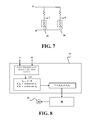
- FIG. 7 is an example of an electrical diagram for the photoelectric sensors of the first pair of the system shown in FIG. 1 ;
- FIG. 8 is a block diagram depicting an example of how command signals are generated in the first control subunit of the system shown in FIG. 1 ;
- FIG. 9 is an example of an electrical diagram for the photoelectric sensors of the second pair of the system shown in FIG. 1 ;
- FIG. 10 is a block diagram depicting an example of how command signals are generated in the second control subunit of the system shown in FIG. 1 ;
- FIG. 11 is an example of an electrical diagram for the photoelectric sensors of the third pair of the system shown in FIG. 1 ;
- FIG. 12 is a block diagram depicting an example of how command signals are generated in the third control subunit of the system shown in FIG. 1 .
- FIGS. 1 to 3 illustrate an example of a fume extraction system 10 incorporating the proposed concept.
- FIG. 1 is a side view of the system 10 .
- FIGS. 2 and 3 are respectively a top view and a front view of the system 10 shown in FIG. 1 .
- the system 10 includes a fume hood 12 provided at the free end of an articulated exhaust duct robotic arm 14 .
- the fume hood 12 of the illustrated example is generally in the form of a truncated cone, having a wide mouth 13 and a narrow top 15 . Other shapes and configurations are possible.
- the arm 14 of the illustrated example includes two juxtaposed segments, namely a distal segment 16 and a proximal segment 18 .
- the distal segment 16 and the proximal segment 18 can have equal or unequal lengths. Also, it is possible to design the arm 14 with more than two juxtaposed segments.
- the fume hood 12 at the free end of the arm 14 is in fluid communication with a source of vacuum.
- the source of vacuum is a blower 20 provided within a base 22 of the system 10 .
- the base 22 is provided on a movable cart but other configurations and arrangement are possible. Air and fumes aspirated through the fume hood 12 flow inside the segments 16 , 18 of the arm 14 before reaching the base 22 .
- the blower 20 can be powered by an electric motor or by another source of power.
- the air and fumes circulating through the blower 20 are conducted elsewhere in the workplace through an external air duct (not shown) for further handling or scrubbing, or for being discharge into the atmosphere. It is also possible that the air and fumes be filtered or otherwise treated within the base 22 itself.
- the vacuum source can be provided at a remote location.
- proximal segment 18 One end of the proximal segment 18 is connected to the base 22 .
- the opposite end of the proximal segment 18 is pivotally connected to a corresponding end of the distal segment 16 .
- This pivot joint allows the distal segment 16 to be moved in a vertical plane relative to the proximal segment 18 .
- An electric actuator joint motor 24 is provided at the joint to change the relative angle A between the two segments 16 , 18 . It thus permits a pitch motion of the distal segment 16 of the arm 14 , thereby moving the fume hood 12 along a circular path in a vertical plane.
- the angle A can have a range between about 5 and 180 degrees. Other configurations, arrangements and kinds of actuators are also possible.
- the illustrated system 10 further includes a pivot joint between the proximal segment 18 of the arm 14 and the base 22 .
- An electric actuator joint motor 30 is provided to change the pitch angle of the proximal segment 18 , thereby moving the fume hood 12 along a circular path in a vertical plane.
- the proximal segment 18 is mounted to the base 22 using a carriage 25 , which carriage 25 is itself mounted on another pivot joint allowing the arm 14 to be pivoted around a vertical axis 32 .
- An electric actuator joint motor 28 on the side of the carriage 25 is provided to rotate the carriage 25 so as to change the yaw angle of the arm 14 , thereby moving the fume hood 12 along a circular path in a horizontal plane.
- the photoelectric sensors 36 , 38 , 40 , 42 , 44 and 46 are provided under the fume hood 12 , near the open mouth 13 , to sense the presence of the electric welding arc. In the illustrated example, the sensors are located adjacent to the periphery of the open mouth 13 .
- the photoelectric sensors 36 , 38 , 40 , 42 , 44 and 46 can be cadmium sulfide cells.
- a cadmium sulfide cell is a resistor whose resistance decreases with increasing incident light intensity.
- FIG. 4 is a semi-schematic top view of the fume hood 12 .
- the front side is at the top of the figure, as indicated.
- FIG. 4 illustrates an example of the relative positions of the various photoelectric sensors 36 , 38 , 40 , 42 , 44 and 46 of the system 10 shown in FIG. 1 .
- the photoelectric sensors 36 and 38 form a first pair and are spaced apart from one another along a first axis 60 .
- the photoelectric sensors 40 and 42 form a second pair and are spaced apart from one another along a second axis 62 .
- both axes 60 , 62 are orthogonal. They intersect one another substantially at the center of the fume hood 12 .
- the system 10 will seek to maintain the position of the electric welding arc, depicted at 64 , approximately at the center of the fume hood 12 .
- the photoelectric sensors 44 and 46 form a third pair and are spaced apart from one another along a third axis that is substantially parallel to the first axis 60 . In the illustrated example, this third axis is coincident with the first axis 60 .
- the photoelectric sensor 44 is located adjacent to the photoelectric sensor 36 and the photoelectric sensor 46 is located adjacent to the photoelectric sensor 38 .
- FIG. 5 is a block diagram depicting an example of the connections between the photoelectric sensors 36 , 38 , 40 , 42 , 44 and 46 , the control unit 50 and the joint motors 24 , 28 and 30 of the system 10 shown in FIG. 1 . It illustrates that the photoelectric sensors 36 , 38 , 40 , 42 , 44 and 46 are connected to a control unit 50 .
- the control unit 50 generates command signals for the articulated exhaust duct robotic arm 14 so as to automatically position the fume hood 12 over the electric welding arc 64 and maintain a predetermined distance between the fume hood 12 and the electric welding arc 64 without the intervention of the operator of the work tool.
- the command signals are based on signals received from the three pairs of photoelectric sensors 36 , 38 , 40 , 42 , 44 and 46 .
- the control unit 50 of the illustrated example is located within the base 22 , as schematically illustrated in FIG. 1 . Other arrangements and configurations are also possible.
- the control unit 50 is designed to receive the signals from the various photoelectric sensors 36 , 38 , 40 , 42 , 44 and 46 , process the information and determine if the fume hood 12 needs to be repositioned over the electric welding arc 64 . If the fume hood 12 needs to be repositioned, the control unit 50 sends command signals to one or more of the joint motors 24 , 28 , and 30 .
- control unit 50 can be designed so that no command signal is sent to the joint motors 24 , 28 , and 30 if no arc is detected by one or more of the photoelectric sensors 36 , 38 , 40 , 42 , 44 and 46 .
- This arrangement permits arc sensing well outside the immediate perimeter of the fume hood 12 .
- a higher gain on the associated joint motor is used to bring the fume hood 12 quickly to the desired location.
- a lower gain is used for more stable operation and the remaining sensors will come into play.
- the control unit 50 includes a first control subunit 52 that generates command signals for a motion of the fume hood 12 along a first path above the electric welding arc 64 based on the signals received from the photoelectric sensors 36 , 38 of the first pair.
- the first axis 60 is tangential to the first path.
- the motion of the fume hood 12 along the first path can be considered to be substantially parallel to the first axis 60 .
- the control unit 50 also includes a second control subunit 54 that generates command signals for a motion of the fume hood 12 along a second path above the electric welding arc 64 based on signals received from the photoelectric sensors 40 , 42 of the second pair.
- the second axis 62 is tangential to the second path.
- the motion of the fume hood 12 along the second path can be considered to be substantially parallel to the second axis 62 .
- the control unit 50 further includes a third control subunit 56 that generates command signals for a motion of the fume hood 12 along a third path based on the signals received from the photoelectric sensors 36 , 38 of the first pair and the photoelectric sensors 44 , 46 of third pair.
- the motion along the third path substantially corresponds to a height distance variation between the fume hood 12 and the electric welding arc 64 .
- the photoelectric sensors 36 and 38 of the first pair provide side to side arc location feedback to the joint motor 28 through the first control subunit 52 .
- the photoelectric sensors 40 and 42 of the second pair provide forward and rearward arc location feedback to the joint motor 24 through the second control subunit 54 .
- Vertical tracking is achieved using the photoelectric sensor pairs 36 / 44 and 38 / 46 .
- Each joint motor 24 , 28 and 30 operates independently of the other two.
- the salient features of this arrangement are twofold: simpler controls and the ability to track the arc 64 in both horizontal and vertical planes.
- FIG. 6 is an example of a semi-schematic front view of the fume hood 12 of the system 10 shown in FIG. 1 . It illustrates that the first and third pair of photoelectric sensors are each symmetrically disposed with reference to a medial plane, which medial plane extends vertically at the center of the fume hood 12 in FIG. 6 .
- the photoelectric sensors 36 , 38 of the first pair define an angle with reference to the medial plane that differs from an angle that the photoelectric sensors 44 , 46 of the third pair define with the medial plane.
- the adjacent photoelectric sensors 36 , 44 as well as the adjacent photoelectric sensors 38 , 46 define a relative angle between them.
- the photoelectric sensor 44 is located adjacent to the photoelectric sensor 36 to provide arc location information along their common sides between which extends axis 90 .
- the photoelectric sensor 46 is located adjacent to the photoelectric sensor 38 to provide arc location information along their common sides between which extends axis 92 .
- These converging axes 90 , 92 provide vertical arc location feedback to joint motor 30 through the third control subunit 56 .
- the photoelectric sensors 36 , 38 , 40 , 42 , 44 and 46 can be mounted in a tube or the like so as to gather light from a specific direction. Light comes from a cone-like area, as depicted in FIG. 6 .
- the central axes of the cone-like area of the photoelectric sensors 36 , 38 , 44 and 46 are depicted at 70 , 72 , 74 and 76 , respectively.
- FIG. 7 is an example of an electrical diagram for the photoelectric sensors 36 , 38 of the first pair of the system 10 shown in FIG. 1 .
- the signals of the photoelectric sensor 36 are read at terminal A and the signals of the photoelectric sensor 38 are read at terminal B.
- the signals are obtained by reading the voltage at terminals A and B.
- FIG. 8 is a block diagram depicting an example an example of how command signals are generated in the first control subunit 52 of the system 10 shown in FIG. 1 .
- the signals from terminals A and B are first checked to see if one of the photoelectric sensors 36 , 38 senses light above a minimum level.
- the minimum light level can be set as a voltage such as 4.5 V.
- the resistance of a photoelectric sensor generally decreases as it receives more light, a very bright light may yield a voltage such as 0.5 V.
- the first control subunit 52 will compare the signal from A and B by subtracting them. This will give a value ⁇ 1 . If ⁇ 1 ⁇ 0, this means that the two photoelectric sensors 36 , 38 are not receiving the same amount of light from the arc 64 . The system 10 assumes that the arc 64 is closer to the one receiving more light and the fume hood 12 will be moved towards the side receiving more light.
- the value of ⁇ 1 can be positive or negative, which will indicate the direction of the motion to the joint motor 28 .
- the illustrated example further includes a selection between two possible motion speeds.
- the first control subunit 52 checks if the value of ⁇ 1 is lower or higher than a predetermined value ⁇ .
- a relatively high value of ⁇ 1 indicates that arc 64 is relatively distant from one of the photoelectric sensors 36 , 38 .
- the motion speed will then be higher so as to position the fume hood 12 more quickly over the arc 64 .
- the gain k 1 is higher than the gain k 2 .
- the value of ⁇ 1 will be lower.
- the motion speed will be reduced by using a lower gain k 2 .
- the command signals go through an amplifier 80 from which electrical power is supplied to the joint motor 28 .
- FIG. 9 is an example of an electrical diagram for the photoelectric sensors 40 , 42 of the second pair of the system 10 shown in FIG. 1 .
- the signals of the photoelectric sensor 40 are read at terminal C and the signals of the photoelectric sensor 42 are read at terminal D.
- the signals are obtained by reading the voltage at terminals C and D.
- FIG. 10 is a block diagram depicting an example an example of how command signals are generated in the second control subunit 54 in the system 10 shown in FIG. 1 .
- the signals from terminals C and D are first checked to see if one of them sense light above a minimum level, for instance using the same manner as for the first control subunit 52 .
- the second control subunit 54 will compare the signal from C and D by subtracting them. This will give a value ⁇ 2 . If ⁇ 2 ⁇ 0, this means that the two photoelectric sensors 40 , 42 are not receiving the same amount of light from the arc 64 . The system 10 assumes that the arc 64 is then closer to the one receiving more light, thus that the fume hood 12 needs to be moved towards the side receiving more light.
- the value of ⁇ 2 can be positive or negative, which will indicate the direction of the motion to the joint motor 24 .
- the illustrated example further includes a selection between two possible motion speeds.
- the second control subunit 54 checks if the value of ⁇ 2 is lower or higher than a predetermined value ⁇ .
- a relatively high value of ⁇ 2 indicates that arc 64 is relatively distant from one of the photoelectric sensors 40 , 42 .
- the motion speed will then be higher so as to position the fume hood 12 more quickly.
- the gain k 1 is higher than the gain k 2 .
- the motion speed will be reduced to the gain k 2 for the fine adjustments.
- the gains k 1 and k 2 can also be different in the two control subunits 52 , 54 .
- the command signals go through an amplifier 82 from which electrical power is supplied to the joint motor 24 .
- FIG. 11 is an example of an electrical diagram for the photoelectric sensors 44 , 46 of the third pair of the system 10 shown in FIG. 1 .
- the signals of the photoelectric sensor 44 are read at terminal E and the signals of the photoelectric sensor 46 are read at terminal F.
- the signals are obtained by reading the voltage at terminals E and F.
- FIG. 12 is a block diagram depicting an example an example of how command signals are generated in the third control subunit 56 of the system 10 shown in FIG. 1 .
- the third control subunit 56 first checks if the first control subunit 52 has a k 2 gain. This is indicative of the presence of the arc 64 and that the fume hood 12 is also at or close to the desired position above the arc 64 .
- the third control subunit 56 does not generate command signals if no arc is detected or if the fume hood 12 is being moved at the high motion speed.
- Other configurations and arrangements are also possible.
- the third control subunit 56 will compare the signal from A and E by subtracting them and will compare the signal from B and F by subtracting them.
- the first comparison yields a first value ⁇ 3A and the second comparison yields a second value ⁇ 3B .
- the first and second values are then added together.
- the result is a value indicative of the need to change the height distance h between the fume hood 12 and the arc 64 .
- the command signals go through an amplifier 84 from which electrical power is supplied to the joint motor 30 .
- control subunits 52 , 54 and 56 can be done through software and/or hardware components.
- the comparators and the adder can be included in a dedicated control circuit or programmed in a computer.
- the goal of the system 10 is to center the arc 64 under the fume hood 12 and keep the height distance h constant.
- This height distance h substantially corresponds to the point where axes 90 , 92 meet, plus or minus any possible adjustments in height.
- This arrangement is able to compensate for a variation in the light intensity received at the photoelectric sensors 36 , 38 , 44 and 46 simply because the arc 64 is off centered.
- point Y and point Z are both at the same height distance h than the electric welding arc 64 depicted at the center. If the arc 64 would initially appear at point Y, the intensity of the light sensed by the photoelectric sensors 36 , 44 will be greater than that sensed by the photoelectric sensors 38 , 46 . However, the difference between the light sensed by the photoelectric sensors 36 , 44 on one side is proportional to the difference between the light sensed by the photoelectric sensors 38 , 46 on the other side. Since point Y is at the correct height, no command signals will be generated to the joint motor 30 for changing the height distance h of the fume hood 12 . A similar explanation also applies to point Z.
- the height distance h between the hood 12 and the arc 64 can be adjusted by the operator via an adjustment knob on the fume hood 12 or elsewhere on the system 10 . Turning the knob varies a biasing voltage. This biasing voltage is added to the sum of ⁇ 3A and ⁇ 3B , as shown in FIG. 12 .
- the magnitude of the signals from the photoelectric sensors 36 , 38 , 40 , 42 , 44 and 46 to the control unit 50 is directly proportional to the magnitude of the arc displacement.
- a welding gun as schematically illustrated in FIG. 1 at 34
- at least one of the photoelectric sensors 36 , 38 , 40 and 42 of the first two pairs will sense the electric welding arc 64 if needed. This initiates the tracking operation.
- the fume hood 12 is then quickly centered over the arc 64 .
- all of the photoelectric sensors 36 , 38 , 40 , 42 , 44 and 46 are feeding arc location information to the control unit 50 .
- the photoelectric sensors 36 , 38 , 40 , 42 , 44 and 46 detect the change in position of the arc 64 .
- the magnitude of the signal sent by each of the photoelectric sensors 36 , 38 , 40 , 42 , 44 and 46 to the control unit 50 is directly proportional to the light intensity from the arc 64 received at each photoelectric sensor 36 , 38 , 40 , 42 , 44 and 46 .
- the control unit 50 analyzes the change in position by comparing the output signals of the photoelectric sensors.
- the control unit 50 then sends commands to the joint motors 24 , 28 , and 30 so as to reposition the fume hood 12 over the arc 64 in a direction that will bring the sensors output at the same level.
- the fume hood 12 can be kept centered and at a predetermined height distance h from the arc 64 . Since only the difference in intensity (as seen by the respective photoelectric sensors) is used to control the positioning of the fume hood 12 , the arc intensity or even the nature of the arc is transparent to the system 10 .
- Each of the joint motors 24 , 28 , and 30 may be fitted with an internal slip clutch.
- Each slip clutch is designed to allow the corresponding joint motor 24 , 28 , and 30 to rotate even if the corresponding joint connection cannot be pivoted. This way, if the fume hood 12 or any other part of the articulated exhaust duct robotic arm 14 encounters an obstacle, the slip clutches can preclude further movements of the arm 14 and/or the joint motors 24 , 28 and 30 to be damaged.
- the slip clutches can also allow the operator to position the fume hood 12 manually before operating the work tool without damaging the joint motors 24 , 28 , and 30 .
- a stop button 48 FIG. 1
- the present concept further provides a method of automatically positioning a fume hood 12 above an electric welding arc 64 during a welding operation on a workpiece 34 , the fume hood 12 being mounted at the free end of a robotic arm 14 .
- the method includes:
- Generating command signals for the robotic arm 14 may include generating a first set of command signals based on a difference between the light levels sensed at the first and the second location, the first set of command signals controlling movements of the fume hood 12 along a first path above the arc 64 so as to center the arc 64 in-between the first and the second location. It may also include generating a second set of command signals based on a difference between the light levels sensed at the third and the fourth location, the second set of command signals controlling movements of the fume hood 12 along a second path above the arc 64 so as to center the arc 64 in-between the third and the fourth location.
- generating command signals for the robotic arm 14 may include:
- (c) generating a third set of command signals based on the results in (a) and (b), the third set of command signals controlling movements of the fume hood 12 so as to set the height distance h between the fume hood 12 and the arc 64 .
- the third set of command signals can be based on an addition of the results in (a) and (b).
- Sensing the light level received from the arc at the fifth and the sixth location under the fume hood 12 may include sensing light at the fifth location along an axis 74 defining a first relative angle with reference to an axis 70 along which the light is sensed at the first location; and sensing light at the sixth location along an axis 76 defining a second relative angle with reference to an axis 72 along which the light is sensed at the second location.
- the first and the second relative angle can be substantially equal.
- a fume extraction system incorporating the proposed concept, as well as a method of extracting fumes from a work area using the proposed concept, will not be affected by the relative orientation of the work tool or the nature of the welding process and can provide a more dependable operation than ever before without the need of a complex construction. Using this arrangement also considerably reduces the likelihood of faults due for instance to the presence of dense fumes to be exhausted from around the workpiece.
- the articulated exhaust duct robotic arm can be constructed differently than what is shown and described.
- the arm may be constructed with one or more flexible tubes supported by rigid beam-like arm segments to which the motorized joints are mounted. Many other constructions are also possible.
- the photoelectric sensors 44 , 46 can be located adjacent to the photoelectric sensors 40 , 42 instead of the photoelectric sensors 36 , 38 .
- the photoelectric sensors 40 , 42 would constitute the first pair of photoelectric sensors and the photoelectric sensors 36 , 38 would constitute the second pair of photoelectric sensors.
- the third axis along which the third pair of photoelectric sensors is disposed does not necessarily need to be coincident with the first axis along which the first pair of photoelectric sensors is disposed.
- the photoelectric sensors do not necessarily need to be cadmium sulfide cells. Other suitable kinds of photoelectric sensors could be used as well, for instance photodiodes.
- the base does not need to be a mobile device as shown and described. Other configurations and arrangements are possible.
- the base can be a fixed device or even be a structure, such as a wall, a floor or a ceiling.
Abstract
Description
-
- sensing the light level received from the
arc 64 at a first and a second location under thefume hood 12, the first and the second location being spaced apart along afirst axis 60; - sensing the light level received from the arc at a third and a fourth location under the
fume hood 12, the third and the fourth location being spaced apart along asecond axis 62 that is orthogonal to thefirst axis 60; - sensing the light level received from the arc at a fifth and a sixth location under the
fume hood 12, the fifth location being adjacent to the first location and the sixth location being adjacent to the second location; and - generating command signals for the
robotic arm 14 based on the light levels sensed at the six locations such that thefume hood 12 is moved to a given height distance h right above thearc 64 and automatically follows thearc 64 when thearc 64 moves over the workpiece 34.
- sensing the light level received from the
Claims (8)
Priority Applications (1)
| Application Number | Priority Date | Filing Date | Title |
|---|---|---|---|
| US13/383,767 US8892222B2 (en) | 2009-07-17 | 2010-07-16 | Fume extraction system with automatic fume hood positioning |
Applications Claiming Priority (3)
| Application Number | Priority Date | Filing Date | Title |
|---|---|---|---|
| US22641009P | 2009-07-17 | 2009-07-17 | |
| PCT/CA2010/001095 WO2011006245A1 (en) | 2009-07-17 | 2010-07-16 | Fume extraction system with automatic fume hood positioning |
| US13/383,767 US8892222B2 (en) | 2009-07-17 | 2010-07-16 | Fume extraction system with automatic fume hood positioning |
Publications (2)
| Publication Number | Publication Date |
|---|---|
| US20120111845A1 US20120111845A1 (en) | 2012-05-10 |
| US8892222B2 true US8892222B2 (en) | 2014-11-18 |
Family
ID=43448835
Family Applications (1)
| Application Number | Title | Priority Date | Filing Date |
|---|---|---|---|
| US13/383,767 Expired - Fee Related US8892222B2 (en) | 2009-07-17 | 2010-07-16 | Fume extraction system with automatic fume hood positioning |
Country Status (4)
| Country | Link |
|---|---|
| US (1) | US8892222B2 (en) |
| EP (1) | EP2454031A4 (en) |
| CA (1) | CA2764308A1 (en) |
| WO (1) | WO2011006245A1 (en) |
Cited By (12)
| Publication number | Priority date | Publication date | Assignee | Title |
|---|---|---|---|---|
| US20150000232A1 (en) * | 2013-06-28 | 2015-01-01 | Illinois Tool Works Inc. | Three-phase portable airborne component extractor with rotational direction control |
| US9468958B2 (en) | 2012-03-16 | 2016-10-18 | Illinois Tool Works Inc. | Airborne component extractor with adjustable flow rates |
| US9821351B2 (en) | 2011-11-11 | 2017-11-21 | Illinois Tool Works Inc. | Welding fume extractor |
| US9839948B2 (en) | 2013-01-29 | 2017-12-12 | Illinois Tool Works Inc. | Fume evacuation system |
| US20190076135A1 (en) * | 2006-10-06 | 2019-03-14 | Covidien Lp | System and method for non-contact electronic articulation sensing |
| US10242317B2 (en) | 2014-11-25 | 2019-03-26 | Illinois Tool Works Inc. | System for estimating the amount and content of fumes |
| US10808953B2 (en) | 2013-06-28 | 2020-10-20 | Illinois Tool Works Inc. | Airborne component extractor with baffled debris collection |
| US11014132B2 (en) | 2015-07-16 | 2021-05-25 | Illinois Tool Works Inc. | Extractor with end-mounted positive pressure system |
| US11141808B2 (en) | 2011-02-01 | 2021-10-12 | Illinois Tool Works Inc. | Fume extractor for welding applications |
| US11324847B2 (en) * | 2018-05-07 | 2022-05-10 | Dalian University Of Technology | Automatic source-seeking indoor pollution purifying and removing device and method |
| US11530826B2 (en) | 2015-07-16 | 2022-12-20 | Illinois Tool Works Inc. | Extractor with segmented positive pressure airflow system |
| US20230204204A1 (en) * | 2020-06-02 | 2023-06-29 | Reno2Blu Inc. | Lighting System With Vacuum Intake |
Families Citing this family (10)
| Publication number | Priority date | Publication date | Assignee | Title |
|---|---|---|---|---|
| US9981351B2 (en) * | 2014-11-07 | 2018-05-29 | RSV Welder Repair, Inc. | Welding accessory apparatus |
| WO2017211362A1 (en) * | 2016-06-06 | 2017-12-14 | Fractum 2012 Aps | Exhaust and filtering system and method for dividing metal by-products process |
| CN106863327A (en) * | 2017-03-29 | 2017-06-20 | 国家电网公司 | A kind of intelligent machine arm dust pelletizing system based on human bioequivalence |
| RU2722712C1 (en) * | 2019-07-23 | 2020-06-03 | Павел Геннадьевич Владимиров | Device for air cleaning in working zone of nail master |
| CN111545547A (en) * | 2020-05-19 | 2020-08-18 | 青岛铭宏智能装备科技有限公司 | Novel dust removal equipment |
| CN112453002B (en) * | 2020-10-31 | 2021-11-26 | 江苏科技大学 | Automatic tracking welding fume collecting and processing device |
| CN112317922A (en) * | 2020-11-17 | 2021-02-05 | 内蒙古北方重型汽车股份有限公司 | Automatic arc light tracking device for electric welding and use method thereof |
| CN112958967B (en) * | 2021-03-25 | 2022-12-02 | 机械工业第九设计研究院股份有限公司 | Double-layer fan cover of automatic station welding smoke dust processing system of welding workshop robot |
| US11179666B1 (en) * | 2021-04-07 | 2021-11-23 | Larry Young | Systems and methods for removal of pollutants |
| CN114227071A (en) * | 2021-12-17 | 2022-03-25 | 武汉科沃斯风机有限公司 | Automatic forming and processing device for fan frame |
Citations (81)
| Publication number | Priority date | Publication date | Assignee | Title |
|---|---|---|---|---|
| US1000000A (en) * | 1910-04-25 | 1911-08-08 | Francis H Holton | Vehicle-tire. |
| US2994763A (en) * | 1959-12-10 | 1961-08-01 | Gen Electric | Arc stray control |
| US3209121A (en) * | 1962-09-04 | 1965-09-28 | Union Carbide Corp | Electrode proximity control |
| US3233076A (en) * | 1964-09-21 | 1966-02-01 | Welding Research Inc | Welding control system |
| US3303321A (en) * | 1965-04-08 | 1967-02-07 | Chicago Bridge & Iron Co | Position control device for welding apparatus |
| US3370151A (en) * | 1964-05-13 | 1968-02-20 | Air Reduction | Control system using radiant-energy detector scanning |
| US3555235A (en) * | 1967-11-13 | 1971-01-12 | Ibm | Metallic surface fusion apparatus |
| US3588466A (en) * | 1969-01-16 | 1971-06-28 | Air Reduction | Pulsed power welding system with suppressed pulse start |
| US3594542A (en) * | 1969-07-11 | 1971-07-20 | Sumikin Welding Electrode Co | Continuous lay down arc welding method |
| US3602687A (en) * | 1969-06-23 | 1971-08-31 | Battelle Development Corp | Arc length control |
| US3702915A (en) * | 1970-10-23 | 1972-11-14 | Astro Arc Co | Automatic melt-thru welding method and apparatus |
| US3818817A (en) * | 1972-01-04 | 1974-06-25 | B Nederman | Adjustable assembly for exhausting out fumes |
| US3819902A (en) * | 1971-10-04 | 1974-06-25 | North American Rockwell | Pattern welding control device |
| US3826894A (en) * | 1973-06-06 | 1974-07-30 | Harnischfeger Corp | Spot welding apparatus for welding end conductors in cylindrical electrical machine elements |
| US3858025A (en) * | 1971-10-04 | 1974-12-31 | North American Rockwell | Pattern welding process and control device |
| US4058299A (en) * | 1975-08-07 | 1977-11-15 | Erik Allan Lindkvist | Apparatus for removing polluting matter arising in flame cutting and like operations |
| US4093844A (en) * | 1976-09-14 | 1978-06-06 | Arcair Company | Arc length measurement and control by optical scanning |
| US4151395A (en) * | 1976-07-06 | 1979-04-24 | CRC-Crose, International, Inc. | Method and apparatus for electric arc and analogous welding under precision control |
| GB1546067A (en) | 1976-06-30 | 1979-05-16 | Marshall D | Apparatus for drawing off noxious gases and fumes |
| US4163650A (en) * | 1978-07-24 | 1979-08-07 | Tepco, Incorporated | Portable electronic precipitator |
| US4192986A (en) * | 1976-08-18 | 1980-03-11 | Hitachi, Ltd. | Method and apparatus for automatic weld line tracing |
| US4287405A (en) * | 1979-10-02 | 1981-09-01 | Mitsubishi Jukogyo Kabushiki Kaisha | Process and apparatus for exhausting fumes produced by arc welding |
| US4358471A (en) * | 1978-07-11 | 1982-11-09 | Trw Inc. | Control apparatus |
| US4359622A (en) * | 1980-05-19 | 1982-11-16 | Vanzetti Infrared & Computer Systems, Inc. | Controller for spot welding |
| US4379548A (en) * | 1980-03-07 | 1983-04-12 | Estel Hoogovens Bv. | Exhaust system especially for use in the cast house of a blast furnace |
| US4399346A (en) * | 1981-05-29 | 1983-08-16 | Kearney Frank W | Optoelectronic weld travel speed sensor |
| JPS58154462A (en) | 1982-03-09 | 1983-09-13 | Amano Corp | Method and apparatus for collecting welding fume |
| JPS6078198A (en) | 1983-09-30 | 1985-05-02 | 高丸工業株式会社 | Hume dust collecting method for manual welding and device thereof |
| US4649426A (en) * | 1984-06-12 | 1987-03-10 | The United States Of America As Represented By The United States Department Of Energy | Electronic imaging system and technique |
| US4675501A (en) * | 1983-10-29 | 1987-06-23 | Trumpf Gmbh & Co. | Laser apparatus with novel beam aligning means and method of laser processing of workpieces using same |
| US4706553A (en) * | 1984-03-05 | 1987-11-17 | Phoenix Controls Corp. | Fume hood controller |
| US4724751A (en) * | 1985-07-16 | 1988-02-16 | Horst Jentzsch | System for exhausting and collecting gases, in particular motor vehicle exhaust gases in assembly or factory halls |
| US4797528A (en) * | 1987-12-08 | 1989-01-10 | Arcair Company | Vacuum carbon arc metal removal process and apparatus |
| US4860644A (en) * | 1988-02-29 | 1989-08-29 | Donaldson Company, Inc. | Articulatable fume exhauster trunk |
| US4881018A (en) * | 1987-12-18 | 1989-11-14 | Nippondenso Co., Ltd. | Manually assistable electric driving device |
| US5015822A (en) * | 1989-11-13 | 1991-05-14 | Mig Vac Inc. | Nozzle structure in welding gun |
| US5036754A (en) * | 1990-04-17 | 1991-08-06 | Diversitech Equipment & Sales (1984) Ltd. | Autotracking fume extraction exhaust hood |
| US5051599A (en) * | 1989-01-26 | 1991-09-24 | Leybold Aktiengesellschaft | Device for recognizing the impact site of a charge carrier beam on a target |
| JPH03291170A (en) | 1990-04-04 | 1991-12-20 | Matsushita Electric Ind Co Ltd | Weld fume collector |
| US5079404A (en) * | 1990-10-24 | 1992-01-07 | Frank Zamuner | Welding torch with fume-extraction hood |
| US5159737A (en) * | 1988-10-05 | 1992-11-03 | Nippon Metal Co., Ltd. | Dust collection apparatus |
| US5211602A (en) * | 1989-04-13 | 1993-05-18 | J H Plymoth Ab | Arrangement in fume extraction arms |
| US5336130A (en) * | 1993-03-04 | 1994-08-09 | Metal-Fab, Inc. | Adjustable exhauster arm assembly |
| US5398978A (en) * | 1993-12-02 | 1995-03-21 | Henlex Inc. | Adjustable coupling for linking conduits |
| US5499946A (en) * | 1993-09-09 | 1996-03-19 | Euromate Industrial Air Cleaning Systems B.V. | Device for exhausting gas or the like |
| US5514851A (en) * | 1994-04-11 | 1996-05-07 | The United States Of America As Represented By The Secretary Of Commerce | Prevention of contact tube melting in arc welding |
| US5591244A (en) * | 1995-06-07 | 1997-01-07 | Simon Roofing And Sheet Metal Corp. | System for removal of noxious fumes |
| US5702493A (en) * | 1996-10-31 | 1997-12-30 | Everetts; Randy Roger | Welding fume funnel with magnetic coupling means |
| US5738148A (en) * | 1995-06-27 | 1998-04-14 | Coral S.P.A. | Universal connector hose for joining an extractor to an element for extracting fumes from a factory workplace |
| US5762664A (en) * | 1996-12-18 | 1998-06-09 | National Tool And Equipment, Inc. | Mobile vessel for removal of noxious fumes |
| US5951725A (en) * | 1995-06-07 | 1999-09-14 | National Tool And Equipment, Inc. | System for removal of noxious fumes |
| WO2000025948A1 (en) | 1998-10-30 | 2000-05-11 | Giuseppe Poggioni | Automatic motorised arm for aspirating welding fumes |
| US6109826A (en) * | 1999-06-03 | 2000-08-29 | Cimline, Inc. | Melter and applicator for applying filling material to paved surfaces |
| US6290740B1 (en) * | 1999-09-15 | 2001-09-18 | Sportsman, Inc. | Large size clean air workstation |
| US6322618B1 (en) * | 1998-10-19 | 2001-11-27 | Texas Electroniques Canada Inc. | Adjustable duct assembly for fume and dust removal and filter cleaner |
| US6358137B1 (en) * | 2000-04-17 | 2002-03-19 | Siemens Building Technologies, Inc. | Laboratory fume hood control apparatus having rotary sash door position sensor |
| US20020050061A1 (en) * | 2000-06-29 | 2002-05-02 | Daido Komyoji | Method and apparatus for forming pattern onto panel substrate |
| US6503139B2 (en) * | 1997-03-04 | 2003-01-07 | Coral S.P.A. | All-purpose conduit for conveying harmful fumes or gases away from a work station |
| US6506139B2 (en) * | 1998-10-02 | 2003-01-14 | Luk Lamellen Und Kupplungsbau Beteiligungs Kg | Transmission with an electro-mechanical energy converter |
| US6534020B1 (en) * | 1997-07-09 | 2003-03-18 | Garlock Equipment Co. | Fume recovery methods |
| US6540603B1 (en) * | 1999-02-15 | 2003-04-01 | Juha Koskinen | Method and system for the regulation of ventilation in a welding workshop |
| US6548783B1 (en) * | 2001-10-03 | 2003-04-15 | General Electric Company | Apparatus for electric arc overlay welding |
| US20030117596A1 (en) * | 2001-04-06 | 2003-06-26 | Nikon Corporation | Exposure apparatus, substrate processing system, and device meanufacturing method |
| US20030126962A1 (en) * | 2002-01-04 | 2003-07-10 | Bland William E. | Digital photofinishing mehtod and apparatus |
| US6617547B1 (en) * | 2002-09-10 | 2003-09-09 | Ilich Abdurachmanov | Arc stray controlling welding apparatus |
| US6626813B1 (en) * | 1997-10-27 | 2003-09-30 | Ranpak Corp. | Cushioning conversion system and method for making a coil of cushioning product |
| US6648748B1 (en) * | 2002-06-11 | 2003-11-18 | Keith Ferlin | Vacuum conduit system for removal of fumes and air borne particulate matter |
| US6744012B2 (en) * | 2000-12-07 | 2004-06-01 | Honda Giken Kogyo Kabushiki Kaisha | Control method of arc welding and arc welder |
| US6770834B1 (en) * | 2000-03-02 | 2004-08-03 | Kent Deshotel | Welding machine |
| US6772932B1 (en) * | 2002-11-25 | 2004-08-10 | Scott P. Halstead | Automated welding system utilizing overhead robots |
| US6994619B2 (en) * | 2003-03-04 | 2006-02-07 | Triatek, Inc. | Optical sash sensing system for fume hoods |
| US20060032692A1 (en) * | 2004-08-12 | 2006-02-16 | Akihiro Ima | Transaxle of multi-wheel drive vehicle |
| US7248940B2 (en) * | 2001-06-01 | 2007-07-24 | Thyssen Laser-Technik Gmbh | Method and device for the robot-controlled cutting of workpieces to be assembled by means of laser radiation |
| US20070187378A1 (en) * | 2004-10-13 | 2007-08-16 | Erdogan Karakas | Device for carrying out a joint, separation, or suface treatment process, particularly a welding process |
| US20080218713A1 (en) * | 2006-08-31 | 2008-09-11 | Nikon Corporation | Movable body drive method and movable body drive system, pattern formation method and apparatus, exposure method and apparatus, and device manufacturing method |
| US7513922B2 (en) * | 2006-03-29 | 2009-04-07 | Yuan-Tai Cheng | Air filter for electric welding |
| US20090295258A1 (en) * | 2008-05-21 | 2009-12-03 | Caliendo Guy P | Actuator arrangement with worm gear and rotational output |
| US20100010672A1 (en) * | 2008-07-10 | 2010-01-14 | Yulun Wang | Docking system for a tele-presence robot |
| US20100030379A1 (en) * | 2006-12-19 | 2010-02-04 | Koninklijke Philips Electronics N.V. | Method of controlling an autonomous device |
| US7677961B2 (en) * | 2004-09-30 | 2010-03-16 | JMP Aquisition Corp. | Fume hood drive system to prevent cocking of a sash |
| US7954451B2 (en) * | 2004-11-09 | 2011-06-07 | Nordson Corporation | Closed loop adhesive registration system |
-
2010
- 2010-07-16 EP EP10799319.8A patent/EP2454031A4/en not_active Withdrawn
- 2010-07-16 WO PCT/CA2010/001095 patent/WO2011006245A1/en active Application Filing
- 2010-07-16 US US13/383,767 patent/US8892222B2/en not_active Expired - Fee Related
- 2010-07-16 CA CA2764308A patent/CA2764308A1/en not_active Abandoned
Patent Citations (85)
| Publication number | Priority date | Publication date | Assignee | Title |
|---|---|---|---|---|
| US1000000A (en) * | 1910-04-25 | 1911-08-08 | Francis H Holton | Vehicle-tire. |
| US2994763A (en) * | 1959-12-10 | 1961-08-01 | Gen Electric | Arc stray control |
| US3209121A (en) * | 1962-09-04 | 1965-09-28 | Union Carbide Corp | Electrode proximity control |
| US3370151A (en) * | 1964-05-13 | 1968-02-20 | Air Reduction | Control system using radiant-energy detector scanning |
| US3233076A (en) * | 1964-09-21 | 1966-02-01 | Welding Research Inc | Welding control system |
| US3303321A (en) * | 1965-04-08 | 1967-02-07 | Chicago Bridge & Iron Co | Position control device for welding apparatus |
| US3555235A (en) * | 1967-11-13 | 1971-01-12 | Ibm | Metallic surface fusion apparatus |
| US3588466A (en) * | 1969-01-16 | 1971-06-28 | Air Reduction | Pulsed power welding system with suppressed pulse start |
| US3602687A (en) * | 1969-06-23 | 1971-08-31 | Battelle Development Corp | Arc length control |
| US3594542A (en) * | 1969-07-11 | 1971-07-20 | Sumikin Welding Electrode Co | Continuous lay down arc welding method |
| US3702915A (en) * | 1970-10-23 | 1972-11-14 | Astro Arc Co | Automatic melt-thru welding method and apparatus |
| US3819902A (en) * | 1971-10-04 | 1974-06-25 | North American Rockwell | Pattern welding control device |
| US3858025A (en) * | 1971-10-04 | 1974-12-31 | North American Rockwell | Pattern welding process and control device |
| US3818817A (en) * | 1972-01-04 | 1974-06-25 | B Nederman | Adjustable assembly for exhausting out fumes |
| US3826894A (en) * | 1973-06-06 | 1974-07-30 | Harnischfeger Corp | Spot welding apparatus for welding end conductors in cylindrical electrical machine elements |
| US4058299A (en) * | 1975-08-07 | 1977-11-15 | Erik Allan Lindkvist | Apparatus for removing polluting matter arising in flame cutting and like operations |
| GB1546067A (en) | 1976-06-30 | 1979-05-16 | Marshall D | Apparatus for drawing off noxious gases and fumes |
| US4151395A (en) * | 1976-07-06 | 1979-04-24 | CRC-Crose, International, Inc. | Method and apparatus for electric arc and analogous welding under precision control |
| US4192986A (en) * | 1976-08-18 | 1980-03-11 | Hitachi, Ltd. | Method and apparatus for automatic weld line tracing |
| US4093844A (en) * | 1976-09-14 | 1978-06-06 | Arcair Company | Arc length measurement and control by optical scanning |
| US4358471A (en) * | 1978-07-11 | 1982-11-09 | Trw Inc. | Control apparatus |
| US4163650A (en) * | 1978-07-24 | 1979-08-07 | Tepco, Incorporated | Portable electronic precipitator |
| US4287405A (en) * | 1979-10-02 | 1981-09-01 | Mitsubishi Jukogyo Kabushiki Kaisha | Process and apparatus for exhausting fumes produced by arc welding |
| US4379548A (en) * | 1980-03-07 | 1983-04-12 | Estel Hoogovens Bv. | Exhaust system especially for use in the cast house of a blast furnace |
| US4359622A (en) * | 1980-05-19 | 1982-11-16 | Vanzetti Infrared & Computer Systems, Inc. | Controller for spot welding |
| US4399346A (en) * | 1981-05-29 | 1983-08-16 | Kearney Frank W | Optoelectronic weld travel speed sensor |
| JPS58154462A (en) | 1982-03-09 | 1983-09-13 | Amano Corp | Method and apparatus for collecting welding fume |
| JPS6078198A (en) | 1983-09-30 | 1985-05-02 | 高丸工業株式会社 | Hume dust collecting method for manual welding and device thereof |
| US4675501A (en) * | 1983-10-29 | 1987-06-23 | Trumpf Gmbh & Co. | Laser apparatus with novel beam aligning means and method of laser processing of workpieces using same |
| US4706553A (en) * | 1984-03-05 | 1987-11-17 | Phoenix Controls Corp. | Fume hood controller |
| US4706553B1 (en) * | 1984-03-05 | 1991-07-23 | Phoenix Controls Corp | |
| US4649426A (en) * | 1984-06-12 | 1987-03-10 | The United States Of America As Represented By The United States Department Of Energy | Electronic imaging system and technique |
| US4724751A (en) * | 1985-07-16 | 1988-02-16 | Horst Jentzsch | System for exhausting and collecting gases, in particular motor vehicle exhaust gases in assembly or factory halls |
| US4797528A (en) * | 1987-12-08 | 1989-01-10 | Arcair Company | Vacuum carbon arc metal removal process and apparatus |
| US4881018A (en) * | 1987-12-18 | 1989-11-14 | Nippondenso Co., Ltd. | Manually assistable electric driving device |
| US4860644A (en) * | 1988-02-29 | 1989-08-29 | Donaldson Company, Inc. | Articulatable fume exhauster trunk |
| US5159737A (en) * | 1988-10-05 | 1992-11-03 | Nippon Metal Co., Ltd. | Dust collection apparatus |
| US5051599A (en) * | 1989-01-26 | 1991-09-24 | Leybold Aktiengesellschaft | Device for recognizing the impact site of a charge carrier beam on a target |
| US5211602A (en) * | 1989-04-13 | 1993-05-18 | J H Plymoth Ab | Arrangement in fume extraction arms |
| US5015822A (en) * | 1989-11-13 | 1991-05-14 | Mig Vac Inc. | Nozzle structure in welding gun |
| JPH03291170A (en) | 1990-04-04 | 1991-12-20 | Matsushita Electric Ind Co Ltd | Weld fume collector |
| US5036754A (en) * | 1990-04-17 | 1991-08-06 | Diversitech Equipment & Sales (1984) Ltd. | Autotracking fume extraction exhaust hood |
| US5079404A (en) * | 1990-10-24 | 1992-01-07 | Frank Zamuner | Welding torch with fume-extraction hood |
| US5336130A (en) * | 1993-03-04 | 1994-08-09 | Metal-Fab, Inc. | Adjustable exhauster arm assembly |
| US5499946A (en) * | 1993-09-09 | 1996-03-19 | Euromate Industrial Air Cleaning Systems B.V. | Device for exhausting gas or the like |
| US5398978A (en) * | 1993-12-02 | 1995-03-21 | Henlex Inc. | Adjustable coupling for linking conduits |
| US5514851A (en) * | 1994-04-11 | 1996-05-07 | The United States Of America As Represented By The Secretary Of Commerce | Prevention of contact tube melting in arc welding |
| US5591244A (en) * | 1995-06-07 | 1997-01-07 | Simon Roofing And Sheet Metal Corp. | System for removal of noxious fumes |
| US5873919A (en) * | 1995-06-07 | 1999-02-23 | Simon Roofing & Sheet Metal Corp. | System for removal of noxious fumes |
| US5951725A (en) * | 1995-06-07 | 1999-09-14 | National Tool And Equipment, Inc. | System for removal of noxious fumes |
| US6022389A (en) * | 1995-06-07 | 2000-02-08 | Simon Roofing & Sheet Metal Corp. | System for removal of noxious fumes |
| US5738148A (en) * | 1995-06-27 | 1998-04-14 | Coral S.P.A. | Universal connector hose for joining an extractor to an element for extracting fumes from a factory workplace |
| US5702493A (en) * | 1996-10-31 | 1997-12-30 | Everetts; Randy Roger | Welding fume funnel with magnetic coupling means |
| US5762664A (en) * | 1996-12-18 | 1998-06-09 | National Tool And Equipment, Inc. | Mobile vessel for removal of noxious fumes |
| US6503139B2 (en) * | 1997-03-04 | 2003-01-07 | Coral S.P.A. | All-purpose conduit for conveying harmful fumes or gases away from a work station |
| US6709637B2 (en) * | 1997-07-09 | 2004-03-23 | Garlock Equipment Co. | Fume recovery apparatus and methods |
| US6534020B1 (en) * | 1997-07-09 | 2003-03-18 | Garlock Equipment Co. | Fume recovery methods |
| US6626813B1 (en) * | 1997-10-27 | 2003-09-30 | Ranpak Corp. | Cushioning conversion system and method for making a coil of cushioning product |
| US6506139B2 (en) * | 1998-10-02 | 2003-01-14 | Luk Lamellen Und Kupplungsbau Beteiligungs Kg | Transmission with an electro-mechanical energy converter |
| US6322618B1 (en) * | 1998-10-19 | 2001-11-27 | Texas Electroniques Canada Inc. | Adjustable duct assembly for fume and dust removal and filter cleaner |
| WO2000025948A1 (en) | 1998-10-30 | 2000-05-11 | Giuseppe Poggioni | Automatic motorised arm for aspirating welding fumes |
| US6540603B1 (en) * | 1999-02-15 | 2003-04-01 | Juha Koskinen | Method and system for the regulation of ventilation in a welding workshop |
| US6109826A (en) * | 1999-06-03 | 2000-08-29 | Cimline, Inc. | Melter and applicator for applying filling material to paved surfaces |
| US6290740B1 (en) * | 1999-09-15 | 2001-09-18 | Sportsman, Inc. | Large size clean air workstation |
| US6770834B1 (en) * | 2000-03-02 | 2004-08-03 | Kent Deshotel | Welding machine |
| US6358137B1 (en) * | 2000-04-17 | 2002-03-19 | Siemens Building Technologies, Inc. | Laboratory fume hood control apparatus having rotary sash door position sensor |
| US20020050061A1 (en) * | 2000-06-29 | 2002-05-02 | Daido Komyoji | Method and apparatus for forming pattern onto panel substrate |
| US6744012B2 (en) * | 2000-12-07 | 2004-06-01 | Honda Giken Kogyo Kabushiki Kaisha | Control method of arc welding and arc welder |
| US20030117596A1 (en) * | 2001-04-06 | 2003-06-26 | Nikon Corporation | Exposure apparatus, substrate processing system, and device meanufacturing method |
| US7248940B2 (en) * | 2001-06-01 | 2007-07-24 | Thyssen Laser-Technik Gmbh | Method and device for the robot-controlled cutting of workpieces to be assembled by means of laser radiation |
| US6548783B1 (en) * | 2001-10-03 | 2003-04-15 | General Electric Company | Apparatus for electric arc overlay welding |
| US20030126962A1 (en) * | 2002-01-04 | 2003-07-10 | Bland William E. | Digital photofinishing mehtod and apparatus |
| US6648748B1 (en) * | 2002-06-11 | 2003-11-18 | Keith Ferlin | Vacuum conduit system for removal of fumes and air borne particulate matter |
| US6617547B1 (en) * | 2002-09-10 | 2003-09-09 | Ilich Abdurachmanov | Arc stray controlling welding apparatus |
| US6772932B1 (en) * | 2002-11-25 | 2004-08-10 | Scott P. Halstead | Automated welding system utilizing overhead robots |
| US6994619B2 (en) * | 2003-03-04 | 2006-02-07 | Triatek, Inc. | Optical sash sensing system for fume hoods |
| US20060032692A1 (en) * | 2004-08-12 | 2006-02-16 | Akihiro Ima | Transaxle of multi-wheel drive vehicle |
| US7677961B2 (en) * | 2004-09-30 | 2010-03-16 | JMP Aquisition Corp. | Fume hood drive system to prevent cocking of a sash |
| US20070187378A1 (en) * | 2004-10-13 | 2007-08-16 | Erdogan Karakas | Device for carrying out a joint, separation, or suface treatment process, particularly a welding process |
| US7954451B2 (en) * | 2004-11-09 | 2011-06-07 | Nordson Corporation | Closed loop adhesive registration system |
| US7513922B2 (en) * | 2006-03-29 | 2009-04-07 | Yuan-Tai Cheng | Air filter for electric welding |
| US20080218713A1 (en) * | 2006-08-31 | 2008-09-11 | Nikon Corporation | Movable body drive method and movable body drive system, pattern formation method and apparatus, exposure method and apparatus, and device manufacturing method |
| US20100030379A1 (en) * | 2006-12-19 | 2010-02-04 | Koninklijke Philips Electronics N.V. | Method of controlling an autonomous device |
| US20090295258A1 (en) * | 2008-05-21 | 2009-12-03 | Caliendo Guy P | Actuator arrangement with worm gear and rotational output |
| US20100010672A1 (en) * | 2008-07-10 | 2010-01-14 | Yulun Wang | Docking system for a tele-presence robot |
Cited By (20)
| Publication number | Priority date | Publication date | Assignee | Title |
|---|---|---|---|---|
| US11406368B2 (en) * | 2006-10-06 | 2022-08-09 | Covidien Lp | System and method for non-contact electronic articulation sensing |
| US20190076135A1 (en) * | 2006-10-06 | 2019-03-14 | Covidien Lp | System and method for non-contact electronic articulation sensing |
| US11141808B2 (en) | 2011-02-01 | 2021-10-12 | Illinois Tool Works Inc. | Fume extractor for welding applications |
| US9821351B2 (en) | 2011-11-11 | 2017-11-21 | Illinois Tool Works Inc. | Welding fume extractor |
| US9498805B2 (en) | 2012-03-16 | 2016-11-22 | Illinois Tool Works Inc. | Airborne component extractor with improved flow paths |
| US9505041B2 (en) | 2012-03-16 | 2016-11-29 | Illinois Tool Works Inc. | Optimized airborne component extractor |
| US9604266B2 (en) | 2012-03-16 | 2017-03-28 | Illinois Tool Works Inc. | Airborne component extractor manifold |
| US9505042B2 (en) | 2012-03-16 | 2016-11-29 | Illinois Tool Works Inc. | Airborne component extractor with improved power and pressure performance |
| US10603698B2 (en) | 2012-03-16 | 2020-03-31 | Illinois Tool Works Inc. | Airborne component extractor hood |
| US9468958B2 (en) | 2012-03-16 | 2016-10-18 | Illinois Tool Works Inc. | Airborne component extractor with adjustable flow rates |
| US9839948B2 (en) | 2013-01-29 | 2017-12-12 | Illinois Tool Works Inc. | Fume evacuation system |
| US11376642B2 (en) | 2013-01-29 | 2022-07-05 | Illinois Tool Works Inc. | Fume evacuation system |
| US20150000232A1 (en) * | 2013-06-28 | 2015-01-01 | Illinois Tool Works Inc. | Three-phase portable airborne component extractor with rotational direction control |
| US10808953B2 (en) | 2013-06-28 | 2020-10-20 | Illinois Tool Works Inc. | Airborne component extractor with baffled debris collection |
| US9272237B2 (en) * | 2013-06-28 | 2016-03-01 | Illinois Tool Works Inc. | Three-phase portable airborne component extractor with rotational direction control |
| US10242317B2 (en) | 2014-11-25 | 2019-03-26 | Illinois Tool Works Inc. | System for estimating the amount and content of fumes |
| US11014132B2 (en) | 2015-07-16 | 2021-05-25 | Illinois Tool Works Inc. | Extractor with end-mounted positive pressure system |
| US11530826B2 (en) | 2015-07-16 | 2022-12-20 | Illinois Tool Works Inc. | Extractor with segmented positive pressure airflow system |
| US11324847B2 (en) * | 2018-05-07 | 2022-05-10 | Dalian University Of Technology | Automatic source-seeking indoor pollution purifying and removing device and method |
| US20230204204A1 (en) * | 2020-06-02 | 2023-06-29 | Reno2Blu Inc. | Lighting System With Vacuum Intake |
Also Published As
| Publication number | Publication date |
|---|---|
| WO2011006245A1 (en) | 2011-01-20 |
| US20120111845A1 (en) | 2012-05-10 |
| EP2454031A4 (en) | 2014-08-20 |
| CA2764308A1 (en) | 2011-01-20 |
| EP2454031A1 (en) | 2012-05-23 |
Similar Documents
| Publication | Publication Date | Title |
|---|---|---|
| US8892222B2 (en) | Fume extraction system with automatic fume hood positioning | |
| EP0524983B1 (en) | Autotracking fume extraction exhaust hood | |
| KR101850386B1 (en) | Robot cleaner and controlling method of the same | |
| JP5803155B2 (en) | Robot position detection device and robot system | |
| US20120296469A1 (en) | Sucking-conveying device having vision sensor and suction unit | |
| CN101378877A (en) | Carriage for automating welding, brazing, cutting and surface treatment processes | |
| SE449313B (en) | MANIPULATOR WELDING AND MANUFACTURING MANUAL | |
| JPWO2017150551A1 (en) | Substrate transport apparatus and teaching method for substrate transport robot | |
| JP2012166314A5 (en) | Position detecting apparatus and position detecting method | |
| CN105246386A (en) | Robot cleaner and control method therefor | |
| JP2016086906A (en) | Self-propelled vacuum cleaner | |
| Nagumo et al. | Human following behavior of an autonomous mobile robot using light-emitting device | |
| JP6924112B2 (en) | A method for obtaining the positional relationship between the board transfer device and the board transfer robot and the board mounting portion. | |
| JP2020116687A (en) | Following robot and work robot system | |
| JP2022541103A (en) | Apparatus for thermally bonding at least one workpiece, comprising a torch and a suction device | |
| JP2019188508A (en) | Working robot system and working robot | |
| JP5579541B2 (en) | Welding method and automatic welding system in automatic welding system | |
| CN102049636A (en) | Welding fume processing device and method for detecting arc light sensing signal | |
| KR101854337B1 (en) | Cleaner and controlling method | |
| JP2020502680A (en) | Method of operating an autonomous mobile vacuum cleaner and such a vacuum cleaner | |
| JPH0631666A (en) | Intelligent robot | |
| CN201537620U (en) | Welding fume processing device | |
| Le et al. | The system design of an autonomous mobile welding robot | |
| JP6955414B2 (en) | Welding robot system and welding method using welding robot system | |
| WO2020045277A1 (en) | Robot and origin position adjustment method therefor |
Legal Events
| Date | Code | Title | Description |
|---|---|---|---|
| AS | Assignment |
Owner name: DIVERSITECH EQUIPMENT AND SALES (1984) LTD., QUEBE Free format text: ASSIGNMENT OF ASSIGNORS INTEREST;ASSIGNORS:SIMMS, MARVIN;SIMMS, JARED;SANTOIANNI, MARIO;REEL/FRAME:027527/0079 Effective date: 20100709 Owner name: DIVERSITECH EQUIPMENT AND SALES (1984) LTD., QUEBE Free format text: ASSIGNMENT OF ASSIGNORS INTEREST;ASSIGNOR:VAN VLIET, MARK;REEL/FRAME:027527/0091 Effective date: 20100709 |
|
| STCF | Information on status: patent grant |
Free format text: PATENTED CASE |
|
| MAFP | Maintenance fee payment |
Free format text: PAYMENT OF MAINTENANCE FEE, 4TH YR, SMALL ENTITY (ORIGINAL EVENT CODE: M2551) Year of fee payment: 4 |
|
| FEPP | Fee payment procedure |
Free format text: ENTITY STATUS SET TO UNDISCOUNTED (ORIGINAL EVENT CODE: BIG.); ENTITY STATUS OF PATENT OWNER: LARGE ENTITY |
|
| FEPP | Fee payment procedure |
Free format text: MAINTENANCE FEE REMINDER MAILED (ORIGINAL EVENT CODE: REM.); ENTITY STATUS OF PATENT OWNER: LARGE ENTITY |
|
| LAPS | Lapse for failure to pay maintenance fees |
Free format text: PATENT EXPIRED FOR FAILURE TO PAY MAINTENANCE FEES (ORIGINAL EVENT CODE: EXP.); ENTITY STATUS OF PATENT OWNER: LARGE ENTITY |
|
| STCH | Information on status: patent discontinuation |
Free format text: PATENT EXPIRED DUE TO NONPAYMENT OF MAINTENANCE FEES UNDER 37 CFR 1.362 |
|
| FP | Lapsed due to failure to pay maintenance fee |
Effective date: 20221118 |