US8893689B2 - Crankcase ventilation self-cleaning coalescer with intermittent rotation - Google Patents
Crankcase ventilation self-cleaning coalescer with intermittent rotation Download PDFInfo
- Publication number
- US8893689B2 US8893689B2 US13/752,535 US201313752535A US8893689B2 US 8893689 B2 US8893689 B2 US 8893689B2 US 201313752535 A US201313752535 A US 201313752535A US 8893689 B2 US8893689 B2 US 8893689B2
- Authority
- US
- United States
- Prior art keywords
- coalescing filter
- rotation
- oil
- engine
- coalescer
- Prior art date
- Legal status (The legal status is an assumption and is not a legal conclusion. Google has not performed a legal analysis and makes no representation as to the accuracy of the status listed.)
- Active
Links
Images


Classifications
-
- F—MECHANICAL ENGINEERING; LIGHTING; HEATING; WEAPONS; BLASTING
- F02—COMBUSTION ENGINES; HOT-GAS OR COMBUSTION-PRODUCT ENGINE PLANTS
- F02M—SUPPLYING COMBUSTION ENGINES IN GENERAL WITH COMBUSTIBLE MIXTURES OR CONSTITUENTS THEREOF
- F02M25/00—Engine-pertinent apparatus for adding non-fuel substances or small quantities of secondary fuel to combustion-air, main fuel or fuel-air mixture
- F02M25/06—Engine-pertinent apparatus for adding non-fuel substances or small quantities of secondary fuel to combustion-air, main fuel or fuel-air mixture adding lubricant vapours
-
- F—MECHANICAL ENGINEERING; LIGHTING; HEATING; WEAPONS; BLASTING
- F01—MACHINES OR ENGINES IN GENERAL; ENGINE PLANTS IN GENERAL; STEAM ENGINES
- F01M—LUBRICATING OF MACHINES OR ENGINES IN GENERAL; LUBRICATING INTERNAL COMBUSTION ENGINES; CRANKCASE VENTILATING
- F01M13/00—Crankcase ventilating or breathing
- F01M13/04—Crankcase ventilating or breathing having means for purifying air before leaving crankcase, e.g. removing oil
-
- F—MECHANICAL ENGINEERING; LIGHTING; HEATING; WEAPONS; BLASTING
- F01—MACHINES OR ENGINES IN GENERAL; ENGINE PLANTS IN GENERAL; STEAM ENGINES
- F01M—LUBRICATING OF MACHINES OR ENGINES IN GENERAL; LUBRICATING INTERNAL COMBUSTION ENGINES; CRANKCASE VENTILATING
- F01M1/00—Pressure lubrication
- F01M1/10—Lubricating systems characterised by the provision therein of lubricant venting or purifying means, e.g. of filters
- F01M2001/1007—Lubricating systems characterised by the provision therein of lubricant venting or purifying means, e.g. of filters characterised by the purification means combined with other functions
- F01M2001/1021—Lubricating systems characterised by the provision therein of lubricant venting or purifying means, e.g. of filters characterised by the purification means combined with other functions comprising self cleaning systems
-
- F—MECHANICAL ENGINEERING; LIGHTING; HEATING; WEAPONS; BLASTING
- F01—MACHINES OR ENGINES IN GENERAL; ENGINE PLANTS IN GENERAL; STEAM ENGINES
- F01M—LUBRICATING OF MACHINES OR ENGINES IN GENERAL; LUBRICATING INTERNAL COMBUSTION ENGINES; CRANKCASE VENTILATING
- F01M13/00—Crankcase ventilating or breathing
- F01M2013/0038—Layout of crankcase breathing systems
- F01M2013/005—Layout of crankcase breathing systems having one or more deoilers
- F01M2013/0061—Layout of crankcase breathing systems having one or more deoilers having a plurality of deoilers
- F01M2013/0072—Layout of crankcase breathing systems having one or more deoilers having a plurality of deoilers in series
-
- F—MECHANICAL ENGINEERING; LIGHTING; HEATING; WEAPONS; BLASTING
- F01—MACHINES OR ENGINES IN GENERAL; ENGINE PLANTS IN GENERAL; STEAM ENGINES
- F01M—LUBRICATING OF MACHINES OR ENGINES IN GENERAL; LUBRICATING INTERNAL COMBUSTION ENGINES; CRANKCASE VENTILATING
- F01M13/00—Crankcase ventilating or breathing
- F01M13/04—Crankcase ventilating or breathing having means for purifying air before leaving crankcase, e.g. removing oil
- F01M2013/0422—Separating oil and gas with a centrifuge device
-
- F—MECHANICAL ENGINEERING; LIGHTING; HEATING; WEAPONS; BLASTING
- F01—MACHINES OR ENGINES IN GENERAL; ENGINE PLANTS IN GENERAL; STEAM ENGINES
- F01M—LUBRICATING OF MACHINES OR ENGINES IN GENERAL; LUBRICATING INTERNAL COMBUSTION ENGINES; CRANKCASE VENTILATING
- F01M13/00—Crankcase ventilating or breathing
- F01M13/04—Crankcase ventilating or breathing having means for purifying air before leaving crankcase, e.g. removing oil
- F01M2013/0438—Crankcase ventilating or breathing having means for purifying air before leaving crankcase, e.g. removing oil with a filter
-
- Y—GENERAL TAGGING OF NEW TECHNOLOGICAL DEVELOPMENTS; GENERAL TAGGING OF CROSS-SECTIONAL TECHNOLOGIES SPANNING OVER SEVERAL SECTIONS OF THE IPC; TECHNICAL SUBJECTS COVERED BY FORMER USPC CROSS-REFERENCE ART COLLECTIONS [XRACs] AND DIGESTS
- Y02—TECHNOLOGIES OR APPLICATIONS FOR MITIGATION OR ADAPTATION AGAINST CLIMATE CHANGE
- Y02T—CLIMATE CHANGE MITIGATION TECHNOLOGIES RELATED TO TRANSPORTATION
- Y02T10/00—Road transport of goods or passengers
- Y02T10/10—Internal combustion engine [ICE] based vehicles
- Y02T10/12—Improving ICE efficiencies
-
- Y02T10/121—
Definitions
- the invention relates to internal combustion engine crankcase ventilation separators, particularly coalescers.
- crankcase ventilation separators are known in the prior art.
- One type of separator uses inertial impaction air-oil separation for removing oil particles from the crankcase blowby gas or aerosol by accelerating the blowby gas stream to high velocities through nozzles or orifices and directing same against an impactor, causing a sharp directional change effecting the oil separation.
- Another type of separator uses coalescence in a coalescing filter for removing oil droplets.
- the present invention arose during continuing development efforts in the latter noted air-oil separation technology, namely removal of oil from the crankcase blowby gas stream by coalescence using a coalescing filter.
- FIG. 1 is a sectional view of a coalescing filter assembly.
- FIG. 2 is a sectional view of another coalescing filter assembly.
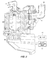
- FIG. 3 is like FIG. 2 and shows another embodiment.
- FIG. 4 is a sectional view of another coalescing filter assembly.
- FIG. 5 is a schematic view illustrating operation of the assembly of FIG. 4 .
- FIG. 6 is a schematic system diagram illustrating an engine intake system.
- FIG. 7 is a schematic diagram illustrating a control option for the system of FIG. 6 .
- FIG. 8 is a flow diagram illustrating an operational control for the system of FIG. 6 .
- FIG. 9 is like FIG. 8 and shows another embodiment.
- FIG. 10 is a schematic sectional view show a coalescing filter assembly.
- FIG. 11 is an enlarged view of a portion of FIG. 10 .
- FIG. 12 is a schematic sectional view of a coalescing filter assembly.
- FIG. 13 is a schematic sectional view of a coalescing filter assembly.
- FIG. 14 is a schematic sectional view of a coalescing filter assembly.
- FIG. 15 is a schematic sectional view of a coalescing filter assembly.
- FIG. 16 is a schematic sectional view of a coalescing filter assembly.
- FIG. 17 is a schematic view of a coalescing filter assembly.
- FIG. 18 is a schematic sectional view of a coalescing filter assembly.
- FIG. 19 is a schematic diagram illustrating a control system.
- FIG. 20 is a schematic diagram illustrating a control system.
- FIG. 21 is a schematic diagram illustrating a control system.
- FIG. 22 is a graph showing efficiency vs. particle size.
- FIG. 23 shows a control system for intermittent operation.
- FIG. 24 shows one form of intermittent operation.
- FIG. 25 is a graph showing restriction vs. flow.
- FIG. 1 shows an internal combustion engine crankcase ventilation rotating coalescer 20 separating air from oil in blowby gas 22 from engine crankcase 24 .
- a coalescing filter assembly 26 includes an annular rotating coalescing filter element 28 having an inner periphery 30 defining a hollow interior 32 , and an outer periphery 34 defining an exterior 36 .
- inlet port 38 supplies blowby gas 22 from crankcase 24 to hollow interior 32 as shown at arrows 40 .
- An outlet port 42 delivers cleaned separated air from the noted exterior zone 36 as shown at arrows 44 .
- the direction of blowby gas flow is inside-out, namely radially outwardly from hollow interior 32 to exterior 36 as shown at arrows 46 .
- Oil in the blowby gas is forced radially outwardly from inner periphery 30 by centrifugal force, to reduce clogging of the coalescing filter element 28 otherwise caused by oil sitting on inner periphery 30 .
- This also opens more area of the coalescing filter element to flow-through, whereby to reduce restriction and pressure drop.
- Centrifugal force drives oil radially outwardly from inner periphery 30 to outer periphery 34 to clear a greater volume of coalescing filter element 28 open to flow-through, to increase coalescing capacity.
- Separated oil drains from outer periphery 34 .
- Drain port 48 communicates with exterior 36 and drains separated oil from outer periphery 34 as shown at arrow 50 , which oil may then be returned to the engine crankcase as shown at arrow 52 from drain 54 .
- Centrifugal force pumps blowby gas from the crankcase to hollow interior 32 The pumping of blowby gas from the crankcase to hollow interior 32 increases with increasing speed of rotation of coalescing filter element 28 .
- the increased pumping of blowby gas 22 from crankcase 24 to hollow interior 32 reduces restriction across coalescing filter element 28 .
- a set of vanes may be provided in hollow interior 32 as shown in dashed line at 56 , enhancing the noted pumping.
- the noted centrifugal force creates a reduced pressure zone in hollow interior 32 , which reduced pressure zone sucks blowby gas 22 from crankcase 24 .
- coalescing filter element 28 is driven to rotate by a mechanical coupling to a component of the engine, e.g. axially extending shaft 58 connected to a gear or drive pulley of the engine.
- coalescing filter element 28 is driven to rotate by a fluid motor, e.g. a pelton or turbine drive wheel 60 , FIG. 2 , driven by pumped pressurized oil from the engine oil pump 62 and returning same to engine crankcase sump 64 .
- FIG. 2 uses like reference numerals from FIG. 1 where appropriate to facilitate understanding. Separated cleaned air is supplied through pressure responsive valve 66 to outlet 68 which is an alternate outlet to that shown at 42 in FIG. 1 .
- coalescing filter element 28 is driven to rotate by an electric motor 70 , FIG. 3 , having a drive output rotary shaft 72 coupled to shaft 58 .
- coalescing filter element 28 is driven to rotate by magnetic coupling to a component of the engine, FIGS. 4 , 5 .
- An engine driven rotating gear 74 has a plurality of magnets such as 76 spaced around the periphery thereof and magnetically coupling to a plurality of magnets 78 spaced around inner periphery 30 of the coalescing filter element such that as gear or driving wheel 74 rotates, magnets 76 move past, FIG. 5 , and magnetically couple with magnets 78 , to in turn rotate the coalescing filter element as a driven member.
- FIG. 1 an electric motor 70
- FIG. 3 having a drive output rotary shaft 72 coupled to shaft 58 .
- coalescing filter element 28 is driven to rotate by magnetic coupling to a component of the engine, FIGS. 4 , 5 .
- FIG. 5 provides a gearing-up effect to rotate the coalescing filter assembly at a greater rotational speed (higher angular velocity) than driving gear or wheel 74 , e.g. where it is desired to provide a higher rotational speed of the coalescing filter element.
- Oil saturation of coalescing filter element 28 decreases with increasing rotational speed of the coalescing filter element. Oil drains from outer periphery 34 , and the amount of oil drained increases with increasing rotational speed of coalescing filter element 28 . Oil particle settling velocity in coalescing filter element 28 acts in the same direction as the direction of air flow through the coalescing filter element. The noted same direction enhances capture and coalescence of oil particles by the coalescing filter element.
- the system provides a method for separating air from oil in internal combustion engine crankcase ventilation blowby gas by introducing a G force in coalescing filter element 28 to cause increased gravitational settling in the coalescing filter element, to improve particle capture and coalescence of submicron oil particles by the coalescing filter element.
- the method includes providing an annular coalescing filter element 28 , rotating the coalescing filter element, and providing inside-out flow through the rotating coalescing filter element.
- the system provides a method for reducing crankcase pressure in an internal combustion engine crankcase generating blowby gas.
- the method includes providing a crankcase ventilation system including a coalescing filter element 28 separating air from oil in the blowby gas, providing the coalescing filter element as an annular element having a hollow interior 32 , supplying the blowby gas to the hollow interior, and rotating the coalescing filter element to pump blowby gas out of crankcase 24 and into hollow interior 32 due to centrifugal force forcing the blowby gas to flow radially outwardly as shown at arrows 46 through coalescing filter element 28 , which pumping effects reduced pressure in crankcase 24 .
- crankcase ventilation system provides open crankcase ventilation (OCV), wherein the cleaned air separated from the blowby gas is discharged to the atmosphere.
- OCV open crankcase ventilation
- CCV closed crankcase ventilation
- the cleaned air separated from the blowby gas is returned to the engine, e.g. is returned to the combustion air intake system to be mixed with the incoming combustion air supplied to the engine.
- FIG. 6 shows a closed crankcase ventilation (CCV) system 100 for an internal combustion engine 102 generating blowby gas 104 in a crankcase 106 .
- the system includes an air intake duct 108 supplying combustion air to the engine, and a return duct 110 having a first segment 112 supplying the blowby gas from the crankcase to air-oil coalescer 114 to clean the blowby gas by coalescing oil therefrom and outputting cleaned air at output 116 , which may be outlet 42 of FIG. 1 , 68 of FIG. 2 , 82 of FIG. 4 .
- Return duct 110 includes a second segment 118 supplying the cleaned air from coalescer 114 to air intake duct 108 to join the combustion air being supplied to the engine.
- Coalescer 114 is variably controlled according to a given condition of the engine, to be described.
- Coalescer 114 has a variable efficiency variably controlled according to a given condition of the engine.
- coalescer 114 is a rotating coalescer, as above, and the speed of rotation of the coalescer is varied according to the given condition of the engine.
- the given condition is engine speed.
- the coalescer is driven to rotate by an electric motor, e.g. 70 , FIG. 3 .
- the electric motor is a variable speed electric motor to vary the speed of rotation of the coalescer.
- the coalescer is hydraulically driven to rotate, e.g. FIG. 2 .
- the speed of rotation of the coalescer is hydraulically varied.
- the engine oil pump 62 FIGS.
- a turbocharger system 140 for the internal combustion 102 generating blowby gas 104 in crankcase 106 .
- the system includes the noted air intake duct 108 having a first segment 142 supplying combustion air to a turbocharger 144 , and a second segment 146 supplying turbocharged combustion air from turbocharger 144 to engine 102 .
- Return duct 110 has the noted first segment 112 supplying the blowby gas 104 from crankcase 106 to air-oil coalescer 114 to clean the blowby gas by coalescing oil therefrom and outputting cleaned air at 116 .
- the return duct has the noted second segment 118 supplying cleaned air from coalescer 114 to first segment 142 of air intake duct 108 to join combustion air supplied to turbocharger 144 .
- Coalescer 114 is variably controlled according to a given condition of at least one of turbocharger 144 and engine 102 .
- the given condition is a condition of the turbocharger.
- the coalescer is a rotating coalescer, as above, and the speed of rotation of the coalescer is varied according to turbocharger efficiency. In a further embodiment, the speed of rotation of the coalescer is varied according to turbocharger boost pressure.
- the speed of rotation of the coalescer is varied according to turbocharger boost ratio, which is the ratio of pressure at the turbocharger outlet versus pressure at the turbocharger inlet.
- the coalescer is driven to rotate by an electric motor, e.g. 70 , FIG. 3 .
- the electric motor is a variable speed electric motor to vary the speed of rotation of the coalescer.
- the coalescer is hydraulically driven to rotate, FIG. 2 .
- the speed of rotation of the coalescer is hydraulically varied, FIG. 7 .
- the system provides a method for improving turbocharger efficiency in a turbocharger system 140 for an internal combustion engine 102 generating blowby gas 104 in a crankcase 106 , the system having an air intake duct 108 having a first segment 142 supplying combustion air to a turbocharger 144 , and a second segment 146 supplying turbocharged combustion air from the turbocharger 144 to the engine 102 , and having a return duct 110 having a first segment 112 supplying the blowby gas 104 to air-oil coalescer 114 to clean the blowby gas by coalescing oil therefrom and outputting cleaned air at 116 , the return duct having a second segment 118 supplying the cleaned air from the coalescer 114 to the first segment 142 of the air intake duct to join combustion air supplied to turbocharger 144 .
- the method includes variably controlling coalescer 114 according to a given condition of at least one of turbocharger 144 and engine 102 .
- One embodiment variably controls coalescer 114 according to a given condition of turbocharger 144 .
- a further embodiment provides the coalescer as a rotating coalescer, as above, and varies the speed of rotation of the coalescer according to turbocharger efficiency.
- a further method varies the speed of rotation of coalescer 114 according to turbocharger boost pressure.
- turbocharger boost ratio which is the ratio of pressure at the turbocharger outlet versus pressure at the turbocharger inlet.
- FIG. 8 shows a control scheme for CCV implementation.
- turbocharger efficiency is monitored, and if the turbo efficiency is ok as determined at step 162 , then rotor speed of the coalescing filter element is reduced at step 164 . If the turbocharger efficiency is not ok, then engine duty cycle is checked at step 166 , and if the engine duty cycle is severe then rotor speed is increased at step 168 , and if engine duty cycle is not severe then no action is taken at step 170 .
- FIG. 9 shows a control scheme for OCV implementation.
- Crankcase pressure is monitored at step 172 , and if it is ok as determined at step 174 then rotor speed is reduced at step 176 , and if not ok then ambient temperature is checked at step 178 and if less than 0° C., then at step 180 rotor speed is increased to a maximum to increase warm gas pumping and increase oil-water slinging. If ambient temperature is not less than 0° C., then engine idling is checked at step 182 , and if the engine is idling then at step 184 rotor speed is increased and maintained, and if the engine is not idling, then at step 186 rotor speed is increased to a maximum for five minutes.
- the flow path through the coalescing filter assembly is from upstream to downstream, e.g. in FIG. 1 from inlet port 38 to outlet port 42 , e.g. in FIG. 2 from inlet port 38 to outlet port 68 , e.g. in FIG. 10 from inlet port 190 to outlet port 192 .
- a rotary cone stack separator 194 located in the flow path and separating air from oil in the blowby gas. Cone stack separators are known in the prior art. The direction of blowby gas flow through the rotating cone stack separator is inside-out, as shown at arrows 196 , FIGS. 10-12 .
- Rotating cone stack separator 194 is upstream of rotating coalescer filter element 198 .
- Rotating cone stack separator 194 is in hollow interior 200 of rotating coalescer filter element 198 .
- an annular shroud 202 is provided in hollow interior 200 and is located radially between rotating cone stack separator 194 and rotating coalescer filter element 198 such that shroud 202 is downstream of rotating cone stack separator 194 and upstream of rotating coalescer filter element 198 and such that shroud 202 provides a collection and drain surface 204 along which separated oil drains after separation by the rotating cone stack separator, which oil drains as shown at droplet 206 through drain hole 208 , which oil then joins the oil separated by coalescer 198 as shown at 210 and drains through main drain 212 .
- FIG. 13 shows a further embodiment and uses like reference numerals from above where appropriate to facilitate understanding.
- Rotating cone stack separator 214 is downstream of rotating coalescer filter element 198 .
- the direction of flow through rotating cone stack separator 214 is inside-out.
- Rotating cone stack separator 214 is located radially outwardly of and circumscribes rotating coalescer filter element 198 .
- FIG. 14 shows another embodiment and uses like reference numerals from above where appropriate to facilitate understanding.
- Rotating cone stack separator 216 is downstream of rotating coalescer filter element 198 .
- the direction of flow through rotating cone stack separator 216 is outside-in, as shown at arrows 218 .
- Rotating coalescer filter element 198 and rotating cone stack separator 216 rotate about a common axis 220 and are axially adjacent each other. Blowby gas flows radially outwardly through rotating coalescer filter element 198 as shown at arrows 222 then axially as shown at arrows 224 to rotating cone stack separator 216 then radially inwardly as shown at arrows 218 through rotating cone stack separator 216 .
- FIG. 15 shows another embodiment and uses like reference numerals from above where appropriate to facilitate understanding.
- a second annular rotating coalescer filter element 230 is provided in the noted flow path from inlet 190 to outlet 192 and separates air from oil in the blowby gas. The direction of flow through second rotating coalescer filter element 230 is outside-in as shown at arrow 232 .
- Second rotating coalescer filter element 230 is downstream of first rotating coalescer element 198 .
- First and second rotating coalescer filter elements 198 and 230 rotate about a common axis 234 and are axially adjacent each other.
- Blowby gas flows radially outwardly as shown at arrow 222 through first rotating coalescer filter element 198 then axially as shown at arrow 236 to second rotating coalescer filter element 230 then radially inwardly as shown at arrow 232 through second rotating coalescer filter element 230 .
- the rotating cone stack separator may be perforated with a plurality of drain holes, e.g. 238 , FIG. 13 , allowing drainage therethrough of separated oil.
- FIG. 16 shows another embodiment and uses like reference numerals from above where appropriate to facilitate understanding.
- An annular shroud 240 is provided along the exterior 242 of rotating coalescer filter element 198 and radially outwardly thereof and downstream thereof such that shroud 240 provides a collection and drain surface 244 along which separated oil drains as shown at droplets 246 after coalescence by rotating coalescer filter element 198 .
- Shroud 240 is a rotating shroud and may be part of the filter frame or end cap 248 .
- Shroud 240 circumscribes rotating coalescer filter element 198 and rotates about a common axis 250 therewith.
- Shroud 240 is conical and tapers along a conical taper relative to the noted axis.
- Shroud 240 has an inner surface at 244 radially facing rotating coalescer filter element 198 and spaced therefrom by a radial gap 252 which increases as the shroud extends axially downwardly and along the noted conical taper.
- Inner surface 244 may have ribs such as 254 , FIG. 17 , circumferentially spaced therearound and extending axially and along the noted conical taper and facing rotating coalescer filter element 198 and providing channeled drain paths such as 256 therealong guiding and draining separated oil flow therealong.
- Inner surface 244 extends axially downwardly along the noted conical taper from a first upper axial end 258 to a second lower axial end 260 .
- Second axial end 260 is radially spaced from rotating coalescer filter element 198 by a radial gap greater than the radial spacing of first axial end 258 from rotating coalescer filter element 198 .
- second axial end 260 has a scalloped lower edge 262 , also focusing and guiding oil drainage.
- FIG. 18 shows a further embodiment and uses like reference numerals from above where appropriate to facilitate understanding.
- an upper inlet port 270 is provided, and a pair of possible or alternate outlet ports are shown at 272 and 274 .
- Oil drainage through drain 212 may be provided through a one-way check valve such as 276 to drain hose 278 , for return to the engine crankcase, as above.
- the coalescer can be variably controlled according to a given condition, which may be a given condition of at least one of the engine, the turbocharger, and the coalescer.
- the noted given condition is a given condition of the engine, as above noted.
- the given condition is a given condition of the turbocharger, as above noted.
- the given condition is a given condition of the coalescer.
- the noted given condition is pressure drop across the coalescer.
- the coalescer is a rotating coalescer, as above, and is driven at higher rotational speed when pressure drop across the coalescer is above a predetermined threshold, to prevent accumulation of oil on the coalescer, e.g.
- FIG. 19 shows a control scheme wherein the pressure drop, dP, across the rotating coalescer is sensed, and monitored by the ECM (engine control module), at step 290 , and then it is determined at step 292 whether dP is above a certain value at low engine RPM, and if not, then rotational speed of the coalescer is kept the same at step 294 , and if dP is above a certain value then the coalescer is rotated at a higher speed at step 296 until dP drops down to a certain point.
- the noted given condition is pressure drop across the coalescer, and the noted predetermined threshold is a predetermined pressure drop threshold.
- the coalescer is an intermittently rotating coalescer having two modes of operation, and is in a first stationary mode when a given condition is below a predetermined threshold, and is in a second rotating mode when the given condition is above the predetermined threshold, with hysteresis if desired.
- the first stationary mode provides energy efficiency and reduction of parasitic energy loss.
- the second rotating mode provides enhanced separation efficiency removing oil from the air in the blowby gas.
- the given condition is engine speed
- the predetermined threshold is a predetermined engine speed threshold.
- the given condition is pressure drop across the coalescer
- the predetermined threshold is a predetermined pressure drop threshold.
- the given condition is turbocharger efficiency
- the predetermined threshold is a predetermined turbocharger efficiency threshold.
- the given condition is turbocharger boost pressure
- the predetermined threshold is a predetermined turbocharger boost pressure threshold.
- the given condition is turbocharger boost ratio
- the predetermined threshold is a predetermined turbocharger boost ratio threshold, where, as above noted, turbocharger boost ratio is the ratio of pressure at the turbocharger outlet vs. pressure at the turbocharger inlet.
- FIG. 20 shows a control scheme for an electrical version wherein engine RPM or coalescer pressure drop is sensed at step 298 and monitored by the ECM at step 300 and then at step 302 if the RPM or pressure is above a threshold then rotation of the coalescer is initiated at step 304 , and if the RPM or pressure is not above the threshold then the coalescer is left in the stationary mode at step 306 .
- FIG. 21 shows a mechanical version and uses like reference numerals from above where appropriate to facilitate understanding.
- a check valve, spring or other mechanical component at step 308 senses RPM or pressure and the decision process is carried out at steps 302 , 304 , 306 as above.
- the noted method for improving turbocharger efficiency includes variably controlling the coalescer according to a given condition of at least one of the turbocharger, the engine, and the coalescer.
- One embodiment variably controls the coalescer according to a given condition of the turbocharger.
- the coalescer is provided as a rotating coalescer, and the method includes varying the speed of rotation of the coalescer according to turbocharger efficiency, and in another embodiment according to turbocharger boost pressure, and in another embodiment according to turbocharger boost ratio, as above noted.
- a further embodiment variably controls the coalescer according to a given condition of the engine, and in a further embodiment according to engine speed.
- the coalescer is provided as a rotating coalescer, and the method involves varying the speed of rotation of the coalescer according to engine speed.
- a further embodiment variably controls the coalescer according to a given condition of the coalescer, and in a further version according to pressure drop across the coalescer.
- the coalescer is provided as a rotating coalescer, and the method involves varying the speed of rotation of the coalescer according to pressure drop across the coalescer.
- a further embodiment involves intermittently rotating the coalescer to have two modes of operation including a first stationary mode and a second rotating mode, as above.
- the coalescer coalesces oil from the blowby gas.
- the method includes regenerating and cleaning the coalescer by intermittent rotation thereof.
- FIG. 22 shows fractional efficiency vs. particle size. At particle size greater than about 1.5 ⁇ , efficiency is roughly the same, e.g. 100%, whether the coalescer filter is rotated or not. As particle size decreases, efficiency drops, particularly for lower RPM (revolutions per minute).
- FIG. 23 shows a control system including a pressure drop (dP) sensor or regulator 320 sensing pressure drop across the coalescer and sending a signal to the ECM 322 (engine control module) which in turn outputs a signal to a frequency generator or rotating unit 324 to rotate the coalescer when pressure drop across the latter rises above a given threshold.
- FIG. 24 illustrates intermittent operation wherein the coalescer is stationary at 326 and the pressure drop thereacross increases. When the pressure drop reaches a given threshold such as 328 , the coalescer is rotated, and the pressure drop thereacross decreases as shown at 330 . When the pressure drop reaches a lower threshold such as 332 , the rotation is stopped. The pressure drop then begins increasing again at 334 , and the cycle repeats.
- dP pressure drop
- FIG. 25 shows restriction levels of the same coalescer element after a series of static and rotating modes.
- the first bar indicates the restriction after 2000 hours of operation in a static mode. Rotating the coalescer reduces the restriction from bar 1 to bar 2 , whereafter the rotation is stopped and the restriction increases from bar 2 to bar 3 , whereafter the coalescer element is again rotated and the restriction decreases from bar 3 to bar 4 .
- Various other intermittent operational patterns may be followed.
- Regeneration of the coalescer by intermittent rotation retains high efficiency and clean coalescing filter media and low pressure drop for the life of the coalescer.
- the high efficiency is produced by efficiently draining the liquid from the filter media with intermittent rotation.
- Static coalescers have a finite life and must be serviced and replaced.
- Rotating coalescers provide higher efficiency at a lower pressure drop than static coalescers and can potentially last the life of the engine, but require energy input to cause or drive the rotation, and may be more complex and costly from a first fit point of view.
- Customers are increasingly demanding a crankcase ventilation separator system that will last the life of the engine, provide high oil mist removal efficiency with low restriction, and with minimal to no parasitic energy loss from the engine.
- coalescer fibrous media saturates with contaminants such as soot and oil in the engine crankcase ventilation blowby gas, reducing the life of the coalescer filter element. Fibrous polymer media traps the oil within the fiber matrix, and the build-up of trapped oil ultimately results in a saturated coalescer element condition which raises the crankcase pressure to the point where the coalescer element needs to be changed. Intermittent rotation extends coalescer filter life and reduces parasitic energy loss otherwise needed to accomplish continuous rotation.
- the present method regenerates and cleans the coalescer by applying centrifugal force thereto by intermittent rotation thereof.
- the intermittent rotation is controlled according to a given parameter.
- the given parameter is a condition of the coalescer.
- the given parameter is a condition of the engine.
- the given parameter is crankcase pressure of the engine.
- the given parameter is operational service time of the engine.
- the given parameter is mileage of a vehicle driven by the engine.
- the method includes regenerating and cleaning the coalescer by intermittent operation driven by a rotary shaft.
- the rotary shaft is driven by the engine.
- the method includes regenerating and cleaning the coalescer by intermittent rotation driven by an electric motor.
- the method includes regenerating and cleaning the coalescer by intermittent rotation driven by a hydraulic motor.
- the method includes regenerating and cleaning the coalescer by intermittent rotation driven by pressurized engine oil.
- the method includes regenerating and cleaning the coalescer by intermittent rotation driven by pressurized engine oil driving a pelton turbine.
- the engine has an oil pump pumping lubricating oil to components of the engine, and the method includes regenerating and cleaning the coalescer by intermittent rotation driven by pumped oil from the oil pump.
- the oil pump has a relief valve returning excess oil to a sump to protect against overpressure, and the method includes regenerating and cleaning the coalescer by intermittent rotation driven by excess oil from the relief valve.
- the method includes regenerating and cleaning the coalescer by intermittent rotation commanded when to spin and when not to spin. In one embodiment, the method includes regenerating and cleaning the coalescer by intermittent rotation at a commanded frequency having a plurality of cycles, each cycle having an off interval during which the coalescer is stationary and nonrotated, and an on interval during which the coalescer is rotated. In one embodiment, at least one of a) the commanded frequency, b) the duty cycle of the commanded frequency between the off and on intervals, and c) the speed of rotation during the on interval, is controlled according to a given parameter.
- the method includes pulsing the rotation of the coalescer to provide pulsed rotation thereof, including a plurality of centrifugal force impulses thereto during rotation during the on interval. In one embodiment, during the on interval, the method includes pulsing the rotation of the coalescer to provide a plurality of accelerational bursts during rotation thereof. In one embodiment, the method includes regenerating and cleaning the coalescer by intermittent rotation while the coalescer is mounted to the engine.
- the noted given parameter or trigger for rotation is excess oil flow from the noted relief valve of the oil pump.
- rotation of the coalescer takes place only when the system oil pressure reaches a higher or excess level above that needed to lubricate engine components, and thus the coalescer rotational system would not “steal” oil from the lube system otherwise needed at lower engine RPMs or system pressures.
- the parameter or trigger for coalescer rotation is crankcase pressure.
- the coalescer element is integrated with a pressure sensor on a rotating driveshaft, with the sensor sensing pressure drop across the coalescer media.
Abstract
Description
Claims (24)
Priority Applications (5)
| Application Number | Priority Date | Filing Date | Title |
|---|---|---|---|
| US13/752,535 US8893689B2 (en) | 2010-01-27 | 2013-01-29 | Crankcase ventilation self-cleaning coalescer with intermittent rotation |
| DE112013006531.2T DE112013006531B4 (en) | 2013-01-29 | 2013-04-12 | System and method for regenerating and cleaning an air-oil coalescing filter of a crankcase ventilation system |
| CN201380071163.2A CN104937223B (en) | 2013-01-29 | 2013-04-12 | The crankcase ventilation self-cleaning coalescer of intermittent rotary |
| PCT/US2013/036278 WO2014120257A1 (en) | 2013-01-29 | 2013-04-12 | Crankcase ventilation self-cleaning coalescer with intermittent rotation |
| US14/526,257 US9574469B2 (en) | 2010-01-27 | 2014-10-28 | Crankcase ventilation self-cleaning coalescer with intermittent rotation |
Applications Claiming Priority (9)
| Application Number | Priority Date | Filing Date | Title |
|---|---|---|---|
| US29863510P | 2010-01-27 | 2010-01-27 | |
| US29863010P | 2010-01-27 | 2010-01-27 | |
| US35919210P | 2010-06-28 | 2010-06-28 | |
| US38378710P | 2010-09-17 | 2010-09-17 | |
| US38379010P | 2010-09-17 | 2010-09-17 | |
| US38379310P | 2010-09-17 | 2010-09-17 | |
| US12/969,755 US8807097B2 (en) | 2010-01-27 | 2010-12-16 | Closed crankcase ventilation system |
| US12/969,742 US8794222B2 (en) | 2010-01-27 | 2010-12-16 | Crankcase ventilation inside-out flow rotating coalescer |
| US13/752,535 US8893689B2 (en) | 2010-01-27 | 2013-01-29 | Crankcase ventilation self-cleaning coalescer with intermittent rotation |
Related Parent Applications (2)
| Application Number | Title | Priority Date | Filing Date |
|---|---|---|---|
| US12/969,755 Continuation-In-Part US8807097B2 (en) | 2010-01-27 | 2010-12-16 | Closed crankcase ventilation system |
| US12/969,742 Continuation-In-Part US8794222B2 (en) | 2010-01-27 | 2010-12-16 | Crankcase ventilation inside-out flow rotating coalescer |
Related Child Applications (1)
| Application Number | Title | Priority Date | Filing Date |
|---|---|---|---|
| US14/526,257 Continuation US9574469B2 (en) | 2010-01-27 | 2014-10-28 | Crankcase ventilation self-cleaning coalescer with intermittent rotation |
Publications (2)
| Publication Number | Publication Date |
|---|---|
| US20130167816A1 US20130167816A1 (en) | 2013-07-04 |
| US8893689B2 true US8893689B2 (en) | 2014-11-25 |
Family
ID=48693824
Family Applications (2)
| Application Number | Title | Priority Date | Filing Date |
|---|---|---|---|
| US13/752,535 Active US8893689B2 (en) | 2010-01-27 | 2013-01-29 | Crankcase ventilation self-cleaning coalescer with intermittent rotation |
| US14/526,257 Active US9574469B2 (en) | 2010-01-27 | 2014-10-28 | Crankcase ventilation self-cleaning coalescer with intermittent rotation |
Family Applications After (1)
| Application Number | Title | Priority Date | Filing Date |
|---|---|---|---|
| US14/526,257 Active US9574469B2 (en) | 2010-01-27 | 2014-10-28 | Crankcase ventilation self-cleaning coalescer with intermittent rotation |
Country Status (1)
| Country | Link |
|---|---|
| US (2) | US8893689B2 (en) |
Cited By (7)
| Publication number | Priority date | Publication date | Assignee | Title |
|---|---|---|---|---|
| US20150047582A1 (en) * | 2010-01-27 | 2015-02-19 | Cummins Filtration Ip, Inc. | Crankcase ventilation self-cleaning coalescer with intermittent rotation |
| US20150135663A1 (en) * | 2013-11-19 | 2015-05-21 | Rolls-Royce Deutschland Ltd. & Co., KG | Jet engine comprising a device for spraying oil |
| US9545591B2 (en) | 2010-01-27 | 2017-01-17 | Cummins Filtration Ip, Inc. | Rotating separator with housing preventing separated liquid carryover |
| US9885265B2 (en) | 2010-01-27 | 2018-02-06 | Cummins Filtration Ip Inc. | Crankcase ventilation inside-out flow rotating coalescer |
| US11174764B2 (en) * | 2017-04-13 | 2021-11-16 | Volvo Truck Corporation | Method for controlling the oil pressure of an oil pump in a combustion engine and an oil pressure arrangement |
| US11318403B2 (en) | 2015-08-17 | 2022-05-03 | Cummins Filtration Ip, Inc. | Auto drain system for vacuum and pressure side fuel water separator |
| US11434857B2 (en) | 2017-10-20 | 2022-09-06 | Cummins Filtration Ip, Inc. | Gas/liquid coalescing filter auto drain |
Families Citing this family (15)
| Publication number | Priority date | Publication date | Assignee | Title |
|---|---|---|---|---|
| EP2431583A1 (en) * | 2010-09-15 | 2012-03-21 | Alfa Laval Corporate AB | A device and method for cleaning crankcase gas |
| DE102014222505A1 (en) * | 2014-06-10 | 2015-12-17 | Mahle International Gmbh | oil separator |
| DE102014220157A1 (en) * | 2014-10-06 | 2016-04-07 | Elringklinger Ag | separating |
| WO2016159951A1 (en) * | 2015-03-30 | 2016-10-06 | Cummins Filtration Ip, Inc. | Multiple stage rotating coalescer devices |
| DE112016001918T5 (en) * | 2015-06-09 | 2018-01-11 | Cummins Filtration Ip, Inc. | Systems and methods for rotary separators that maintain positive feedback via a dynamic seal |
| US10537842B2 (en) | 2015-06-09 | 2020-01-21 | Cummins Filtration Ip, Inc. | Systems and methods for utilizing a low-friction rotating coalescer contact seal |
| GB201511321D0 (en) * | 2015-06-29 | 2015-08-12 | Rolls Royce Plc | A de-oiler and a method of using the same |
| CN106468193B (en) * | 2015-08-14 | 2019-05-14 | 科勒公司 | Internal combustion engine and the oil treatment provisions being used therewith |
| WO2017034976A1 (en) | 2015-08-21 | 2017-03-02 | Cummins Filtration Ip, Inc. | High speed rotating crankcase ventilation filter media and media pack |
| CN111389151A (en) * | 2015-08-25 | 2020-07-10 | 康明斯过滤Ip公司 | Filter pre-cleaning machine |
| WO2017040256A1 (en) | 2015-08-28 | 2017-03-09 | Cummins Filtration Ip, Inc | Rotating coalescing element with directed liquid drainage and gas outlet |
| CN112901310B (en) | 2016-04-28 | 2022-12-02 | 康明斯滤清系统知识产权公司 | Inside-out rotating coalescer with gas discharge through hollow shaft |
| DE102016124098A1 (en) * | 2016-12-12 | 2018-06-14 | Hengst Se & Co. Kg | Method for protecting a rotary separator against icing |
| CN110917744A (en) * | 2019-12-10 | 2020-03-27 | 西安圣华农业科技股份有限公司 | Primary filtering device for heat recovery of coke tail gas |
| CN114458415B (en) * | 2022-01-28 | 2024-03-15 | 东风商用车有限公司 | Controllable oil-gas separation system |
Citations (148)
| Publication number | Priority date | Publication date | Assignee | Title |
|---|---|---|---|---|
| US630365A (en) | 1899-01-05 | 1899-08-08 | Ulysse Laplace | Filter attachment for centrifugal machines. |
| US881723A (en) | 1906-05-29 | 1908-03-10 | Robert Scheibe | Separator. |
| US2104683A (en) | 1933-07-06 | 1938-01-04 | Rosen Van | Dust separator |
| US2443875A (en) * | 1943-03-13 | 1948-06-22 | Avco Mfg Corp | Lubricating system for engines |
| US2713960A (en) | 1950-11-22 | 1955-07-26 | Irvin Swartzberg | Feeding and handling mechanism for container filling machines |
| US2714960A (en) | 1952-10-07 | 1955-08-09 | Byron C Schmid | Wet-magnetic separator |
| US2795291A (en) | 1954-07-28 | 1957-06-11 | Gen Motors Corp | Air filter |
| US3073516A (en) | 1959-08-06 | 1963-01-15 | Dorr Oliver Inc | Centrifuges |
| US3234716A (en) | 1961-11-22 | 1966-02-15 | Sevin Roger Joseph | Apparatus for separating dust and other particles from suspension in a gas |
| US3289397A (en) | 1964-03-31 | 1966-12-06 | Gen Dynamics Corp | Aerosol filter |
| US3299335A (en) | 1963-03-12 | 1967-01-17 | Philips Corp | Self-starting direct-current motors having no commutator |
| US3333703A (en) | 1963-06-12 | 1967-08-01 | Purolator Products Inc | Filter housing |
| US3343342A (en) | 1964-05-11 | 1967-09-26 | Rocher Lionel J Du | Filter assembly |
| US3363771A (en) | 1966-08-03 | 1968-01-16 | Brown Charles H | Liquid filter |
| US3447290A (en) | 1967-09-18 | 1969-06-03 | Frick Co | Separator for disentrainment of material from a gaseous fluid stream |
| US3631272A (en) | 1969-04-04 | 1971-12-28 | Daiko Electronics Ind Co Ltd | Dc electric motor using hall elements |
| US3753492A (en) | 1970-06-19 | 1973-08-21 | V Aiello | Separating apparatus |
| US3857687A (en) | 1973-10-09 | 1974-12-31 | W Cook | Centrifugal filter |
| US3935487A (en) | 1974-05-06 | 1976-01-27 | Czerniak Leonard C | Permanent magnet motor |
| US4138234A (en) | 1977-03-17 | 1979-02-06 | Uop Inc. | Holder for annular filter |
| US4189310A (en) | 1977-01-26 | 1980-02-19 | Kabushiki Kaisha Sanetsu | Apparatus for removing oil mist |
| US4223909A (en) | 1979-03-01 | 1980-09-23 | Trak Incorporated | Ski with improved three-dimensional running surface |
| US4249221A (en) | 1979-04-23 | 1981-02-03 | Sli Industries, Inc. | Method and apparatus for preventing contamination of a rotating magnetic disc |
| US4288030A (en) * | 1979-04-12 | 1981-09-08 | The Glacier Metal Company Limited | Centrifugal separator |
| US4311933A (en) | 1979-08-27 | 1982-01-19 | North American Philips Corporation | Brushless direct current motor |
| US4329968A (en) | 1979-04-16 | 1982-05-18 | Nissan Motor Co., Ltd. | Oil separating system for blowby gas |
| US4411675A (en) | 1981-08-03 | 1983-10-25 | Castella Pierre De | Apparatus for the purification of gases |
| US4482365A (en) * | 1982-03-01 | 1984-11-13 | Pall Corporation | Vortex air cleaner and self-cleaning barrier filter assembly for supercharged engines |
| US4561409A (en) | 1984-10-26 | 1985-12-31 | Fernandez John J | Self-cleaning smog control filter for internal combustion engines |
| US4714139A (en) | 1985-10-02 | 1987-12-22 | Mtu Motoren-Und Turbinen Union Muenchen Gmbh | Lubricating system for gas turbine engines and pump for such a system |
| US4871455A (en) | 1986-06-03 | 1989-10-03 | Facet Enterprises, Inc. | Filter assembly with lockable lug means |
| US4908050A (en) | 1987-08-31 | 1990-03-13 | Tabai Espec Co. Ltd. | Oil mist remover |
| US4922604A (en) | 1989-03-13 | 1990-05-08 | Pacific Scientific Company | Method of fabricating an encapsulated motor |
| US4981502A (en) | 1987-11-03 | 1991-01-01 | Mtu Motoren -Und Turbinen-Union | Oil-air separator |
| US5035797A (en) | 1990-02-14 | 1991-07-30 | Stanadyne Automotive Corp. | Key system for filter assembly |
| US5045192A (en) | 1986-06-03 | 1991-09-03 | Facet Enterprises, Inc. | Filter assembly with lockable lug means |
| US5090873A (en) | 1989-12-18 | 1992-02-25 | Copeland Corporation | Crankcase oil separator |
| US5095238A (en) | 1990-04-03 | 1992-03-10 | Minebea Co., Ltd. | Brushless dc motor and rotor magnet |
| US5171430A (en) | 1991-05-17 | 1992-12-15 | Fleetguard, Inc. | Plastic filter |
| US5205848A (en) | 1991-03-29 | 1993-04-27 | Pall France Services | Device ensuring filtration and communication between the atmosphere and the inside of a crankcase |
| US5229671A (en) | 1989-08-16 | 1993-07-20 | Robert Bosch Gmbh | Electromagnetic rotary actuator |
| US5300223A (en) | 1992-01-27 | 1994-04-05 | Allied-Signal Inc. | Quick connect/disconnect oil filter |
| US5342519A (en) | 1993-07-30 | 1994-08-30 | Donaldson Company, Inc. | Fluid filter cartridge with replaceable filter element |
| US5429101A (en) | 1993-02-19 | 1995-07-04 | Filterwerk Mann & Hummel Gmbh | Oil separator for the gases of the crankcase of an internal-combustion engine |
| US5450835A (en) | 1994-11-15 | 1995-09-19 | Cummins Engine Company, Inc. | Oil separator for reducing oil losses from crankcase ventilation |
| US5471966A (en) | 1995-01-25 | 1995-12-05 | Feuling; James J. | Engine air intake filter and crankcase breather oil collection assembly |
| US5536289A (en) * | 1994-02-15 | 1996-07-16 | Firma Carl Freudenberg | Gas-liquid separator |
| US5538626A (en) | 1994-07-13 | 1996-07-23 | Ing, Walter Hengst Gmbh & Co. Kg | Liquid filter |
| US5548893A (en) | 1995-03-20 | 1996-08-27 | Koelfgen; Douglas F. | Spin-on oil filter replacement element |
| US5549821A (en) | 1993-09-29 | 1996-08-27 | Fleetguard, Inc. | Fluid filter assembly for vehicles |
| US5556542A (en) | 1993-09-29 | 1996-09-17 | Fleetguard, Inc. | Fluid filter assembly |
| US5575511A (en) | 1995-04-07 | 1996-11-19 | Flexon, Inc. | Fuel filter coupling bracket |
| US5643448A (en) | 1994-09-26 | 1997-07-01 | Glacier Metal Company Limited | Spin-on filter assembly incorporating a re-usable tubular filter screen |
| US5681461A (en) | 1996-01-31 | 1997-10-28 | Caterpillar Inc. | Fluid filter having a reusable filter housing and central core and a replaceable coreless filter element |
| US5685985A (en) | 1995-12-20 | 1997-11-11 | Baldwin Filters, Inc. | Environmentally friendly filter cartridge |
| US5702602A (en) | 1995-12-20 | 1997-12-30 | Baldwin Filters, Inc. | Filter system with environmentally friendly filter cartridge |
| US5737378A (en) | 1996-06-21 | 1998-04-07 | General Electric Company | Reactor shroud joint |
| US5738785A (en) | 1995-12-20 | 1998-04-14 | Baldwin Filters, Inc. | Oil filter housing |
| US5755842A (en) | 1995-07-05 | 1998-05-26 | Air-Maze Corporation | Air cleaner having removable end cap |
| US5762671A (en) | 1997-02-13 | 1998-06-09 | Farrow; James V. | Multi-size threaded adapter |
| US5770065A (en) | 1993-09-15 | 1998-06-23 | Parker Hannifin Corporation | Fuel filter assembly with replacement element |
| US5837137A (en) | 1996-08-21 | 1998-11-17 | Stanadyne Automotive Corp. | Base/cartridge location and key system for fuel filter assembly |
| US5846416A (en) | 1996-05-24 | 1998-12-08 | Caterpillar Inc. | Fluid filter having a reusable filter housing and a replaceable coreless filter element |
| US5911213A (en) | 1995-08-12 | 1999-06-15 | Firma Ing. Walter Hengst Gmbh & Co. Kg | Process for operating an electric filter for a crankcase ventilator |
| BE1011567A3 (en) | 1997-11-25 | 1999-11-09 | Atlas Copco Airpower Nv | Filter unit and filter element for this |
| US6006924A (en) | 1997-05-14 | 1999-12-28 | Pti Technologies, Inc. | Multi-media filtration system with reusable and demountable filter cartridge |
| US6019717A (en) | 1998-08-19 | 2000-02-01 | Fleetguard, Inc. | Nozzle inlet enhancement for a high speed turbine-driven centrifuge |
| US6068763A (en) | 1997-09-12 | 2000-05-30 | Purolator Products Company | Spin-on oil filter with replaceable element |
| US6123061A (en) | 1997-02-25 | 2000-09-26 | Cummins Engine Company, Inc. | Crankcase ventilation system |
| US6139738A (en) | 1999-03-10 | 2000-10-31 | Parker-Hannifin Corporation | Cartridge filter with integrated threading having anti-rotation feature |
| US6139595A (en) | 1998-09-18 | 2000-10-31 | Fleetguard, Inc. | Air/oil coalescer with centrifugally assisted drainage |
| US6146527A (en) | 1998-04-21 | 2000-11-14 | Parker-Hannifin Corporation | Spin-on filter cartridge with replaceable element |
| US6152120A (en) * | 1999-06-04 | 2000-11-28 | Caterpillar Inc. | Diesel engine system with oil-air separator and method of operation |
| US6213929B1 (en) * | 1998-09-25 | 2001-04-10 | Analytical Engineering, Inc. | Motor driven centrifugal filter |
| US20010012814A1 (en) | 1999-07-12 | 2001-08-09 | May David F. | Motor driven centrifugal filter |
| US6281319B1 (en) | 1999-04-12 | 2001-08-28 | Surgidev Corporation | Water plasticized high refractive index polymer for ophthalmic applications |
| US6364822B1 (en) | 2000-12-07 | 2002-04-02 | Fleetguard, Inc. | Hero-turbine centrifuge with drainage enhancing baffle devices |
| US6506302B2 (en) | 2000-02-16 | 2003-01-14 | Stanadyne Corporation | Key system for ecological filter cartridge and element |
| US20030024870A1 (en) | 2001-07-31 | 2003-02-06 | Reinhart David Matthew | Cartridge filter with integrated threading having anti-rotation feature |
| US6517612B1 (en) | 2001-10-29 | 2003-02-11 | Gore Enterprise Holdings, Inc. | Centrifugal filtration device |
| US20030034016A1 (en) | 2001-08-16 | 2003-02-20 | Harvey William Bernard | Air/oil coalescer with an improved centrifugally assisted drainage |
| US6527821B2 (en) | 1998-11-25 | 2003-03-04 | Msp Corporation | Automatic condensed oil remover |
| EP0844012B1 (en) | 1996-11-20 | 2003-08-13 | Denso Corporation | Oil filter |
| US20030233939A1 (en) | 2002-06-24 | 2003-12-25 | Alfa Laval Corporate Ab | Method of cleaning crankcase gas and a gas cleaning separator |
| US6701580B1 (en) | 2002-12-05 | 2004-03-09 | 3M Innovative Properties Company | Interlocking fastener including adhesive portions |
| US6709477B1 (en) * | 1999-06-30 | 2004-03-23 | Volvo Lastvagnar Ab | Oil separator for small particles |
| US6752924B2 (en) | 2001-04-02 | 2004-06-22 | Donaldson Company, Inc. | Bowl-cartridge filter having interlock mechanism and methods |
| US20040168415A1 (en) * | 2002-11-20 | 2004-09-02 | Mann & Hummel Gmbh | Centrifugal separator |
| US20040206083A1 (en) | 2003-04-16 | 2004-10-21 | Toyota Jidosha Kabushiki Kaisha | Control apparatus for internal combustion engine having motor-driven supercharger |
| US20040214710A1 (en) | 2003-04-23 | 2004-10-28 | Herman Peter K. | Integral air/oil coalescer for a centrifuge |
| US20040226442A1 (en) | 2003-02-17 | 2004-11-18 | Alfa Laval Corporate Ab | Method of treating air on board on a vehicle, and a device for use when performing the method |
| US6821319B1 (en) | 1999-11-15 | 2004-11-23 | Alfa Laval Ab | Method and an apparatus for cleaning of gas |
| US6858056B2 (en) | 2001-09-28 | 2005-02-22 | Rolls-Royce Deutschland Ltd & Co Kg | Oil separator |
| US20050060970A1 (en) | 2003-09-09 | 2005-03-24 | Polderman Hugo Gerardus | Gas/liquid separator |
| US6893478B2 (en) | 2002-03-16 | 2005-05-17 | Rolls-Royce Plc | Air/oil separator |
| US20050120685A1 (en) | 2003-08-23 | 2005-06-09 | Mann & Hummel Gmbh | Centrifugal separator |
| US6925993B1 (en) * | 2004-04-15 | 2005-08-09 | Alfa Laval Corporate Ab | Apparatus for cleaning of crankcase gas |
| US20050223687A1 (en) | 2000-05-18 | 2005-10-13 | Miller Robert K | Filter and forming system |
| US6986805B2 (en) | 2000-12-04 | 2006-01-17 | Donaldson Company, Inc. | Filter system; element configuration; and methods |
| US7000894B2 (en) | 2003-04-25 | 2006-02-21 | Pur Water Purification Products, Inc. | Fluidic cartridges and end pieces thereof |
| US20060048761A1 (en) * | 2002-06-20 | 2006-03-09 | Alfa Laval Corporate Ab | Method and a device for cleaning of crankcase gas |
| US20060090738A1 (en) * | 2003-05-23 | 2006-05-04 | Michael Hoffmann | Centrifugal oil separator for blow-by gases of an internal combustion engine |
| US20060145555A1 (en) | 2004-10-25 | 2006-07-06 | Petro John P | Rotor-stator structure for electrodynamic machines |
| US7081145B2 (en) | 1997-06-27 | 2006-07-25 | Donaldson Company, Inc. | Aerosol separator; and method |
| US20060162305A1 (en) | 2000-08-11 | 2006-07-27 | Reid Roger P | Keyed system for connection of filter cartridge to filter holder |
| CN2809233Y (en) | 2005-04-28 | 2006-08-23 | 新乡县七里营液压件厂 | Oil-gas separator for diesel engine |
| US7104239B2 (en) | 2003-07-22 | 2006-09-12 | Honda Motor Co., Ltd. | Engine crankcase structure |
| US7185643B2 (en) | 2004-10-19 | 2007-03-06 | International Engine Intellectual Property Company, Llc | Combined filter and fill tube |
| US20070062887A1 (en) | 2005-09-20 | 2007-03-22 | Schwandt Brian W | Space optimized coalescer |
| US20070084194A1 (en) | 2005-10-13 | 2007-04-19 | Thomas Holm | Crankcase ventilation system |
| CN1961139A (en) | 2004-06-03 | 2007-05-09 | 阿尔法拉瓦尔股份有限公司 | A device and a method for cleaning of a gas |
| US20070107703A1 (en) | 2005-11-14 | 2007-05-17 | Robert Natkin | Boost control for internal combustion engine using substantially carbon-free fuel |
| US20070163215A1 (en) | 2003-10-07 | 2007-07-19 | Lagerstadt Torgny | Centrifugal separator for cleaning gases |
| US7258111B2 (en) | 2005-05-06 | 2007-08-21 | Toyota Motor Engineering & Manufacturing North America, Inc. | Oil separator |
| US7294948B2 (en) | 2004-10-25 | 2007-11-13 | Novatorque, Inc. | Rotor-stator structure for electrodynamic machines |
| US20070289632A1 (en) | 2004-07-08 | 2007-12-20 | Della Casa Luigi P | Centrifugal Separator for Mixtures in a Liquid or Gaseous Medium Technical Filed |
| US20080009402A1 (en) * | 2006-07-06 | 2008-01-10 | Kane John E | Method and apparatus for separating particles |
| US7338546B2 (en) * | 2006-04-19 | 2008-03-04 | Alfa Laval Corporate Ab | Centrifugal separator for cleaning gas generated by an internal combustion engine and a method for operating the same |
| US20080250772A1 (en) | 2006-04-12 | 2008-10-16 | Mann & Hummel Gmbh | Multi-stage apparatus for separating liquid droplets from gases |
| US20080290018A1 (en) | 2000-08-17 | 2008-11-27 | Bayne Carew | Filter apparatus |
| US7465341B2 (en) * | 2003-04-16 | 2008-12-16 | Alfa Laval Corporate Ab | Apparatus for cleaning of a gas |
| US20090000258A1 (en) | 2006-02-13 | 2009-01-01 | Alfa Laval Corporate Ab | Centrifugal Separator |
| US7473034B2 (en) | 2005-07-28 | 2009-01-06 | Panasonic Corporation | Hydrodynamic bearing device, motor, and disk driving apparatus |
| WO2009005355A1 (en) | 2007-07-03 | 2009-01-08 | Evodos B.V. | Separating device and method |
| US20090013658A1 (en) | 2006-02-13 | 2009-01-15 | Alfa Laval Corporate Ab | Centrifugal separator |
| US20090025562A1 (en) | 2005-06-08 | 2009-01-29 | Alfa Laaval Corporate Ab | Centrifugal separator for cleaning of gas |
| US20090025662A1 (en) | 2007-07-26 | 2009-01-29 | Herman Peter K | Crankcase Ventilation System with Pumped Scavenged Oil |
| US20090050121A1 (en) | 2007-08-23 | 2009-02-26 | Holzmann Mark V | Two Stage Drainage Gas-Liquid Separator |
| US20090126324A1 (en) | 2007-11-15 | 2009-05-21 | Smith Guillermo A | Authorized Filter Servicing and Replacement |
| US20090178964A1 (en) * | 2008-01-14 | 2009-07-16 | Purolator Filters Na Llc | One Piece Combination Anti-Drain Back and Relief Valve |
| US20090186752A1 (en) | 2006-05-15 | 2009-07-23 | Alfa Laval Corporate Ab | Centrifugal separator |
| US20090223496A1 (en) * | 2004-11-29 | 2009-09-10 | Alfa Laval Corporate Ab | Device for cleaning of crankcase gases |
| US20090249756A1 (en) | 2005-05-03 | 2009-10-08 | Donaldson Company, Inc. | Air cleaner; air filter cartridge and method of manufacturing |
| WO2009138872A1 (en) * | 2008-05-16 | 2009-11-19 | Toyota Jidosha Kabushiki Kaisha | Oil mist separator for internal combustion engine |
| US20100011723A1 (en) | 2008-07-16 | 2010-01-21 | Alfa Laval Corporate Ab | Centrifugal separator |
| US20100043734A1 (en) | 2007-07-26 | 2010-02-25 | Cummins Filtration Ip, Inc. | Crankcase Ventilation System with Engine Driven Pumped Scavenged Oil |
| WO2010051994A1 (en) | 2008-11-06 | 2010-05-14 | Hengst Gmbh & Co. Kg | Centrifugal separator |
| CN101189414B (en) | 2005-05-09 | 2010-05-19 | 阿法拉伐特木堡公司 | Apparatus for the purification of gas while bleeding a crank housing |
| US7723887B2 (en) | 2008-02-04 | 2010-05-25 | System General Corporation | Motor rotor |
| US20100180854A1 (en) | 2007-07-13 | 2010-07-22 | Dieter Baumann | Separator for separating oil mist from the crankcase ventilation gas of an internal combustion engine, and functional module and internal combustion engine comprising a separator |
| US7824459B2 (en) | 2006-02-13 | 2010-11-02 | Alfa Laval Corporate Ab | Centrifugal separator |
| CN101549331B (en) | 2009-04-22 | 2010-12-08 | 吉林大学 | Composite oil gas separation method and composite oil gas separator |
| US20110005160A1 (en) | 2008-02-13 | 2011-01-13 | Kazuhiro Nihei | Movable tensegrity structure |
| US20110017155A1 (en) * | 2007-08-02 | 2011-01-27 | Donaldson Company, Inc. | Crank case ventilation filter assembly; and methods |
| US20110180051A1 (en) | 2010-01-27 | 2011-07-28 | Cummins Filtration Ip Inc. | Crankcase Ventilation Inside-Out Flow Rotating Coalescer |
| US20110247309A1 (en) | 2010-01-27 | 2011-10-13 | Cummins Filtration Ip Inc. | Magnetically Driven Rotating Separator |
| US20110252974A1 (en) | 2010-01-27 | 2011-10-20 | Cummins Filtration Ip Inc. | Rotating Coalescer with Keyed Drive |
| US8177875B2 (en) | 2005-02-04 | 2012-05-15 | Donaldson Company, Inc. | Aerosol separator; and method |
Family Cites Families (28)
| Publication number | Priority date | Publication date | Assignee | Title |
|---|---|---|---|---|
| US1306421A (en) | 1919-06-10 | Breathes for internal-combustion engines | ||
| US2553742A (en) | 1948-05-22 | 1951-05-22 | Universal Oil Prod Co | Deposit resistant manifold |
| US3680305A (en) | 1970-09-28 | 1972-08-01 | Raymond S Miller | Clean combustion engine system |
| US4222755A (en) | 1978-11-17 | 1980-09-16 | Grotto Lavon P | Air filter arrangement to permit cleaning without removing element |
| US4298465A (en) | 1979-06-07 | 1981-11-03 | Racor Industries, Inc. | Fuel filter and water separator apparatus |
| US4302517A (en) | 1980-06-26 | 1981-11-24 | Union Carbide Corporation | Unitary seal and cover support gasket for miniature button cells |
| US4643158A (en) | 1982-06-11 | 1987-02-17 | Giannotti Hugo V | Vortex particle separator |
| IT214566Z2 (en) | 1988-06-10 | 1990-05-09 | Leini Torino A | FILTER FOR SEPARATION OF OIL MIST |
| EP0525366B1 (en) | 1991-06-18 | 1995-11-08 | Kuraco Limited | Grease extractor |
| US5564401A (en) | 1995-07-21 | 1996-10-15 | Diesel Research Inc. | Crankcase emission control system |
| US6183407B1 (en) | 1998-04-02 | 2001-02-06 | Alfa Laval Ab | Centrifugal separator having axially-extending, angled separation discs |
| SE514779C2 (en) | 1998-08-20 | 2001-04-23 | Alfa Laval Ab | Carrying means for a centrifugal separator |
| US6337213B1 (en) | 1998-12-21 | 2002-01-08 | The Regents Of The University Of California | Apparatus and method for collection and concentration of respirable particles into a small fluid volume |
| DE10044615A1 (en) | 2000-09-09 | 2002-04-04 | Mahle Filtersysteme Gmbh | Ventilation device for a crankcase |
| SE520453C2 (en) | 2001-11-01 | 2003-07-15 | Alfa Laval Corp Ab | An apparatus for simultaneously purifying a liquid and a gas |
| SE520952C2 (en) | 2002-01-25 | 2003-09-16 | Alfa Laval Corp Ab | An apparatus for simultaneously purifying a liquid and a gas |
| AU2002250018A1 (en) | 2002-02-06 | 2004-02-25 | Pall Corporation | Coalescing and separating arrangements, systems, and methods for liquid mixtures |
| DE10300729A1 (en) | 2003-01-11 | 2004-07-22 | Mann + Hummel Gmbh | Centrifugal oil separator |
| DE20302824U1 (en) | 2003-02-21 | 2004-07-08 | Hengst Gmbh & Co.Kg | Oil separator for cleaning crankcase ventilation gas of an internal combustion engine containing oil mist |
| US7842459B2 (en) | 2004-01-27 | 2010-11-30 | Compugen Ltd. | Nucleotide and amino acid sequences, and assays and methods of use thereof for diagnosis |
| ATE442893T1 (en) | 2005-02-22 | 2009-10-15 | Donaldson Co Inc | AEROSOL SEPARATOR |
| CA2621834A1 (en) | 2005-09-09 | 2007-03-15 | Btu International, Inc. | Microwave combustion system for internal combustion engines |
| US7597809B1 (en) | 2006-03-27 | 2009-10-06 | David Roberts | Methods for removal of oil and other contaminants from water |
| US7789950B2 (en) | 2007-06-15 | 2010-09-07 | Bendix Commercial Vehicle Systems Llc | Air dryer with oil removal filter |
| FR2933626B1 (en) | 2008-07-10 | 2011-01-21 | Filtrauto | DEVICE WITH ROTOR WITH MEDIA COALESCER FOR SEPARATING THE OIL FROM THE CASING GASES OF AN INTERNAL COMBUSTION ENGINE. |
| RU2492935C1 (en) | 2009-07-10 | 2013-09-20 | Альфа Лаваль Корпорейт Аб | Gas cleaner |
| US9194265B2 (en) | 2010-01-27 | 2015-11-24 | Cummins Filtration Ip, Inc. | Rotating separator with housing preventing separated liquid carryover |
| US8893689B2 (en) * | 2010-01-27 | 2014-11-25 | Cummins Filtration Ip, Inc. | Crankcase ventilation self-cleaning coalescer with intermittent rotation |
-
2013
- 2013-01-29 US US13/752,535 patent/US8893689B2/en active Active
-
2014
- 2014-10-28 US US14/526,257 patent/US9574469B2/en active Active
Patent Citations (166)
| Publication number | Priority date | Publication date | Assignee | Title |
|---|---|---|---|---|
| US630365A (en) | 1899-01-05 | 1899-08-08 | Ulysse Laplace | Filter attachment for centrifugal machines. |
| US881723A (en) | 1906-05-29 | 1908-03-10 | Robert Scheibe | Separator. |
| US2104683A (en) | 1933-07-06 | 1938-01-04 | Rosen Van | Dust separator |
| US2443875A (en) * | 1943-03-13 | 1948-06-22 | Avco Mfg Corp | Lubricating system for engines |
| US2713960A (en) | 1950-11-22 | 1955-07-26 | Irvin Swartzberg | Feeding and handling mechanism for container filling machines |
| US2714960A (en) | 1952-10-07 | 1955-08-09 | Byron C Schmid | Wet-magnetic separator |
| US2795291A (en) | 1954-07-28 | 1957-06-11 | Gen Motors Corp | Air filter |
| US3073516A (en) | 1959-08-06 | 1963-01-15 | Dorr Oliver Inc | Centrifuges |
| US3234716A (en) | 1961-11-22 | 1966-02-15 | Sevin Roger Joseph | Apparatus for separating dust and other particles from suspension in a gas |
| US3299335A (en) | 1963-03-12 | 1967-01-17 | Philips Corp | Self-starting direct-current motors having no commutator |
| US3333703A (en) | 1963-06-12 | 1967-08-01 | Purolator Products Inc | Filter housing |
| US3289397A (en) | 1964-03-31 | 1966-12-06 | Gen Dynamics Corp | Aerosol filter |
| US3343342A (en) | 1964-05-11 | 1967-09-26 | Rocher Lionel J Du | Filter assembly |
| US3363771A (en) | 1966-08-03 | 1968-01-16 | Brown Charles H | Liquid filter |
| US3447290A (en) | 1967-09-18 | 1969-06-03 | Frick Co | Separator for disentrainment of material from a gaseous fluid stream |
| US3631272A (en) | 1969-04-04 | 1971-12-28 | Daiko Electronics Ind Co Ltd | Dc electric motor using hall elements |
| US3753492A (en) | 1970-06-19 | 1973-08-21 | V Aiello | Separating apparatus |
| US3857687A (en) | 1973-10-09 | 1974-12-31 | W Cook | Centrifugal filter |
| US3935487A (en) | 1974-05-06 | 1976-01-27 | Czerniak Leonard C | Permanent magnet motor |
| US4189310A (en) | 1977-01-26 | 1980-02-19 | Kabushiki Kaisha Sanetsu | Apparatus for removing oil mist |
| US4138234A (en) | 1977-03-17 | 1979-02-06 | Uop Inc. | Holder for annular filter |
| US4223909A (en) | 1979-03-01 | 1980-09-23 | Trak Incorporated | Ski with improved three-dimensional running surface |
| US4288030A (en) * | 1979-04-12 | 1981-09-08 | The Glacier Metal Company Limited | Centrifugal separator |
| US4329968A (en) | 1979-04-16 | 1982-05-18 | Nissan Motor Co., Ltd. | Oil separating system for blowby gas |
| US4249221A (en) | 1979-04-23 | 1981-02-03 | Sli Industries, Inc. | Method and apparatus for preventing contamination of a rotating magnetic disc |
| US4311933A (en) | 1979-08-27 | 1982-01-19 | North American Philips Corporation | Brushless direct current motor |
| US4411675A (en) | 1981-08-03 | 1983-10-25 | Castella Pierre De | Apparatus for the purification of gases |
| US4482365A (en) * | 1982-03-01 | 1984-11-13 | Pall Corporation | Vortex air cleaner and self-cleaning barrier filter assembly for supercharged engines |
| US4561409A (en) | 1984-10-26 | 1985-12-31 | Fernandez John J | Self-cleaning smog control filter for internal combustion engines |
| US4714139A (en) | 1985-10-02 | 1987-12-22 | Mtu Motoren-Und Turbinen Union Muenchen Gmbh | Lubricating system for gas turbine engines and pump for such a system |
| US4871455A (en) | 1986-06-03 | 1989-10-03 | Facet Enterprises, Inc. | Filter assembly with lockable lug means |
| US5045192A (en) | 1986-06-03 | 1991-09-03 | Facet Enterprises, Inc. | Filter assembly with lockable lug means |
| US4908050A (en) | 1987-08-31 | 1990-03-13 | Tabai Espec Co. Ltd. | Oil mist remover |
| US4981502A (en) | 1987-11-03 | 1991-01-01 | Mtu Motoren -Und Turbinen-Union | Oil-air separator |
| US4922604A (en) | 1989-03-13 | 1990-05-08 | Pacific Scientific Company | Method of fabricating an encapsulated motor |
| US5229671A (en) | 1989-08-16 | 1993-07-20 | Robert Bosch Gmbh | Electromagnetic rotary actuator |
| US5090873A (en) | 1989-12-18 | 1992-02-25 | Copeland Corporation | Crankcase oil separator |
| US5035797A (en) | 1990-02-14 | 1991-07-30 | Stanadyne Automotive Corp. | Key system for filter assembly |
| US5095238A (en) | 1990-04-03 | 1992-03-10 | Minebea Co., Ltd. | Brushless dc motor and rotor magnet |
| US5205848A (en) | 1991-03-29 | 1993-04-27 | Pall France Services | Device ensuring filtration and communication between the atmosphere and the inside of a crankcase |
| US5171430A (en) | 1991-05-17 | 1992-12-15 | Fleetguard, Inc. | Plastic filter |
| US5300223A (en) | 1992-01-27 | 1994-04-05 | Allied-Signal Inc. | Quick connect/disconnect oil filter |
| US5429101A (en) | 1993-02-19 | 1995-07-04 | Filterwerk Mann & Hummel Gmbh | Oil separator for the gases of the crankcase of an internal-combustion engine |
| US5342519A (en) | 1993-07-30 | 1994-08-30 | Donaldson Company, Inc. | Fluid filter cartridge with replaceable filter element |
| US5770065A (en) | 1993-09-15 | 1998-06-23 | Parker Hannifin Corporation | Fuel filter assembly with replacement element |
| US5549821A (en) | 1993-09-29 | 1996-08-27 | Fleetguard, Inc. | Fluid filter assembly for vehicles |
| US5556542A (en) | 1993-09-29 | 1996-09-17 | Fleetguard, Inc. | Fluid filter assembly |
| US5536289A (en) * | 1994-02-15 | 1996-07-16 | Firma Carl Freudenberg | Gas-liquid separator |
| US5538626A (en) | 1994-07-13 | 1996-07-23 | Ing, Walter Hengst Gmbh & Co. Kg | Liquid filter |
| US5643448A (en) | 1994-09-26 | 1997-07-01 | Glacier Metal Company Limited | Spin-on filter assembly incorporating a re-usable tubular filter screen |
| US5450835A (en) | 1994-11-15 | 1995-09-19 | Cummins Engine Company, Inc. | Oil separator for reducing oil losses from crankcase ventilation |
| US5471966A (en) | 1995-01-25 | 1995-12-05 | Feuling; James J. | Engine air intake filter and crankcase breather oil collection assembly |
| US5548893A (en) | 1995-03-20 | 1996-08-27 | Koelfgen; Douglas F. | Spin-on oil filter replacement element |
| US5575511A (en) | 1995-04-07 | 1996-11-19 | Flexon, Inc. | Fuel filter coupling bracket |
| US5755842A (en) | 1995-07-05 | 1998-05-26 | Air-Maze Corporation | Air cleaner having removable end cap |
| US5911213A (en) | 1995-08-12 | 1999-06-15 | Firma Ing. Walter Hengst Gmbh & Co. Kg | Process for operating an electric filter for a crankcase ventilator |
| US5702602A (en) | 1995-12-20 | 1997-12-30 | Baldwin Filters, Inc. | Filter system with environmentally friendly filter cartridge |
| US5685985A (en) | 1995-12-20 | 1997-11-11 | Baldwin Filters, Inc. | Environmentally friendly filter cartridge |
| US5738785A (en) | 1995-12-20 | 1998-04-14 | Baldwin Filters, Inc. | Oil filter housing |
| US5681461A (en) | 1996-01-31 | 1997-10-28 | Caterpillar Inc. | Fluid filter having a reusable filter housing and central core and a replaceable coreless filter element |
| US5846416A (en) | 1996-05-24 | 1998-12-08 | Caterpillar Inc. | Fluid filter having a reusable filter housing and a replaceable coreless filter element |
| US5737378A (en) | 1996-06-21 | 1998-04-07 | General Electric Company | Reactor shroud joint |
| US5837137A (en) | 1996-08-21 | 1998-11-17 | Stanadyne Automotive Corp. | Base/cartridge location and key system for fuel filter assembly |
| EP0844012B1 (en) | 1996-11-20 | 2003-08-13 | Denso Corporation | Oil filter |
| US5762671A (en) | 1997-02-13 | 1998-06-09 | Farrow; James V. | Multi-size threaded adapter |
| US6123061A (en) | 1997-02-25 | 2000-09-26 | Cummins Engine Company, Inc. | Crankcase ventilation system |
| US6006924A (en) | 1997-05-14 | 1999-12-28 | Pti Technologies, Inc. | Multi-media filtration system with reusable and demountable filter cartridge |
| EP0880987B1 (en) | 1997-05-14 | 2004-12-29 | PTI Technologies, Inc. | Filtration unit |
| US7081145B2 (en) | 1997-06-27 | 2006-07-25 | Donaldson Company, Inc. | Aerosol separator; and method |
| US6068763A (en) | 1997-09-12 | 2000-05-30 | Purolator Products Company | Spin-on oil filter with replaceable element |
| BE1011567A3 (en) | 1997-11-25 | 1999-11-09 | Atlas Copco Airpower Nv | Filter unit and filter element for this |
| US6146527A (en) | 1998-04-21 | 2000-11-14 | Parker-Hannifin Corporation | Spin-on filter cartridge with replaceable element |
| US6019717A (en) | 1998-08-19 | 2000-02-01 | Fleetguard, Inc. | Nozzle inlet enhancement for a high speed turbine-driven centrifuge |
| US6139595A (en) | 1998-09-18 | 2000-10-31 | Fleetguard, Inc. | Air/oil coalescer with centrifugally assisted drainage |
| US6213929B1 (en) * | 1998-09-25 | 2001-04-10 | Analytical Engineering, Inc. | Motor driven centrifugal filter |
| US6527821B2 (en) | 1998-11-25 | 2003-03-04 | Msp Corporation | Automatic condensed oil remover |
| US6139738A (en) | 1999-03-10 | 2000-10-31 | Parker-Hannifin Corporation | Cartridge filter with integrated threading having anti-rotation feature |
| US6281319B1 (en) | 1999-04-12 | 2001-08-28 | Surgidev Corporation | Water plasticized high refractive index polymer for ophthalmic applications |
| US6152120A (en) * | 1999-06-04 | 2000-11-28 | Caterpillar Inc. | Diesel engine system with oil-air separator and method of operation |
| US6709477B1 (en) * | 1999-06-30 | 2004-03-23 | Volvo Lastvagnar Ab | Oil separator for small particles |
| US20010012814A1 (en) | 1999-07-12 | 2001-08-09 | May David F. | Motor driven centrifugal filter |
| US6821319B1 (en) | 1999-11-15 | 2004-11-23 | Alfa Laval Ab | Method and an apparatus for cleaning of gas |
| US6506302B2 (en) | 2000-02-16 | 2003-01-14 | Stanadyne Corporation | Key system for ecological filter cartridge and element |
| US20050223687A1 (en) | 2000-05-18 | 2005-10-13 | Miller Robert K | Filter and forming system |
| US20060162305A1 (en) | 2000-08-11 | 2006-07-27 | Reid Roger P | Keyed system for connection of filter cartridge to filter holder |
| US20080290018A1 (en) | 2000-08-17 | 2008-11-27 | Bayne Carew | Filter apparatus |
| US6986805B2 (en) | 2000-12-04 | 2006-01-17 | Donaldson Company, Inc. | Filter system; element configuration; and methods |
| US20090272085A1 (en) | 2000-12-04 | 2009-11-05 | Donaldson Company, Inc. | Filter system; element configuration; and methods |
| US6364822B1 (en) | 2000-12-07 | 2002-04-02 | Fleetguard, Inc. | Hero-turbine centrifuge with drainage enhancing baffle devices |
| US6752924B2 (en) | 2001-04-02 | 2004-06-22 | Donaldson Company, Inc. | Bowl-cartridge filter having interlock mechanism and methods |
| US20030024870A1 (en) | 2001-07-31 | 2003-02-06 | Reinhart David Matthew | Cartridge filter with integrated threading having anti-rotation feature |
| US20030034016A1 (en) | 2001-08-16 | 2003-02-20 | Harvey William Bernard | Air/oil coalescer with an improved centrifugally assisted drainage |
| US6640792B2 (en) | 2001-08-16 | 2003-11-04 | Commins Engine Company, Inc. | Air/oil coalescer with an improved centrifugally assisted drainage |
| US6858056B2 (en) | 2001-09-28 | 2005-02-22 | Rolls-Royce Deutschland Ltd & Co Kg | Oil separator |
| US6517612B1 (en) | 2001-10-29 | 2003-02-11 | Gore Enterprise Holdings, Inc. | Centrifugal filtration device |
| US6893478B2 (en) | 2002-03-16 | 2005-05-17 | Rolls-Royce Plc | Air/oil separator |
| US20060048761A1 (en) * | 2002-06-20 | 2006-03-09 | Alfa Laval Corporate Ab | Method and a device for cleaning of crankcase gas |
| US7152589B2 (en) * | 2002-06-20 | 2006-12-26 | Alfa Laval Corporate Ab | Method and a device for cleaning of crankcase gas |
| CN1671952B (en) | 2002-06-24 | 2010-11-10 | 阿尔法拉瓦尔股份有限公司 | Method of cleaning crankcase gas and a gas cleaning separator |
| US20030233939A1 (en) | 2002-06-24 | 2003-12-25 | Alfa Laval Corporate Ab | Method of cleaning crankcase gas and a gas cleaning separator |
| US6755896B2 (en) | 2002-06-24 | 2004-06-29 | Alfa Laval Corporate Ab | Method of cleaning crankcase gas and a gas cleaning separator |
| US20040168415A1 (en) * | 2002-11-20 | 2004-09-02 | Mann & Hummel Gmbh | Centrifugal separator |
| US6701580B1 (en) | 2002-12-05 | 2004-03-09 | 3M Innovative Properties Company | Interlocking fastener including adhesive portions |
| US7022163B2 (en) | 2003-02-17 | 2006-04-04 | Alfa Laval Corporate Ab | Method of treating air on board on a vehicle, and a device for use when performing the method |
| US20040226442A1 (en) | 2003-02-17 | 2004-11-18 | Alfa Laval Corporate Ab | Method of treating air on board on a vehicle, and a device for use when performing the method |
| US20040206083A1 (en) | 2003-04-16 | 2004-10-21 | Toyota Jidosha Kabushiki Kaisha | Control apparatus for internal combustion engine having motor-driven supercharger |
| US7465341B2 (en) * | 2003-04-16 | 2008-12-16 | Alfa Laval Corporate Ab | Apparatus for cleaning of a gas |
| US20040214710A1 (en) | 2003-04-23 | 2004-10-28 | Herman Peter K. | Integral air/oil coalescer for a centrifuge |
| US7235177B2 (en) | 2003-04-23 | 2007-06-26 | Fleetguard, Inc. | Integral air/oil coalescer for a centrifuge |
| US7000894B2 (en) | 2003-04-25 | 2006-02-21 | Pur Water Purification Products, Inc. | Fluidic cartridges and end pieces thereof |
| US20060090738A1 (en) * | 2003-05-23 | 2006-05-04 | Michael Hoffmann | Centrifugal oil separator for blow-by gases of an internal combustion engine |
| US7377271B2 (en) * | 2003-05-23 | 2008-05-27 | Daimler Ag | Centrifugal oil separator for blow-by gases of an internal combustion engine |
| US7104239B2 (en) | 2003-07-22 | 2006-09-12 | Honda Motor Co., Ltd. | Engine crankcase structure |
| US20050120685A1 (en) | 2003-08-23 | 2005-06-09 | Mann & Hummel Gmbh | Centrifugal separator |
| US20050060970A1 (en) | 2003-09-09 | 2005-03-24 | Polderman Hugo Gerardus | Gas/liquid separator |
| US20070163215A1 (en) | 2003-10-07 | 2007-07-19 | Lagerstadt Torgny | Centrifugal separator for cleaning gases |
| US7396373B2 (en) | 2003-10-07 | 2008-07-08 | 3Nine Ab | Centrifugal separator for cleaning gases |
| US6925993B1 (en) * | 2004-04-15 | 2005-08-09 | Alfa Laval Corporate Ab | Apparatus for cleaning of crankcase gas |
| US20080264251A1 (en) | 2004-06-03 | 2008-10-30 | Alfa Laval Corporate Ab | Device and a Method for Cleaning of a Gas |
| CN1961139A (en) | 2004-06-03 | 2007-05-09 | 阿尔法拉瓦尔股份有限公司 | A device and a method for cleaning of a gas |
| US20070289632A1 (en) | 2004-07-08 | 2007-12-20 | Della Casa Luigi P | Centrifugal Separator for Mixtures in a Liquid or Gaseous Medium Technical Filed |
| US7185643B2 (en) | 2004-10-19 | 2007-03-06 | International Engine Intellectual Property Company, Llc | Combined filter and fill tube |
| US7294948B2 (en) | 2004-10-25 | 2007-11-13 | Novatorque, Inc. | Rotor-stator structure for electrodynamic machines |
| US20060145555A1 (en) | 2004-10-25 | 2006-07-06 | Petro John P | Rotor-stator structure for electrodynamic machines |
| US20090223496A1 (en) * | 2004-11-29 | 2009-09-10 | Alfa Laval Corporate Ab | Device for cleaning of crankcase gases |
| US8177875B2 (en) | 2005-02-04 | 2012-05-15 | Donaldson Company, Inc. | Aerosol separator; and method |
| CN2809233Y (en) | 2005-04-28 | 2006-08-23 | 新乡县七里营液压件厂 | Oil-gas separator for diesel engine |
| US20090249756A1 (en) | 2005-05-03 | 2009-10-08 | Donaldson Company, Inc. | Air cleaner; air filter cartridge and method of manufacturing |
| US7258111B2 (en) | 2005-05-06 | 2007-08-21 | Toyota Motor Engineering & Manufacturing North America, Inc. | Oil separator |
| CN101189414B (en) | 2005-05-09 | 2010-05-19 | 阿法拉伐特木堡公司 | Apparatus for the purification of gas while bleeding a crank housing |
| US20090025562A1 (en) | 2005-06-08 | 2009-01-29 | Alfa Laaval Corporate Ab | Centrifugal separator for cleaning of gas |
| US7473034B2 (en) | 2005-07-28 | 2009-01-06 | Panasonic Corporation | Hydrodynamic bearing device, motor, and disk driving apparatus |
| US20070062887A1 (en) | 2005-09-20 | 2007-03-22 | Schwandt Brian W | Space optimized coalescer |
| US20100229537A1 (en) | 2005-10-13 | 2010-09-16 | Thomas Holm | Crankcase Ventilation System |
| US20070084194A1 (en) | 2005-10-13 | 2007-04-19 | Thomas Holm | Crankcase ventilation system |
| US20070107703A1 (en) | 2005-11-14 | 2007-05-17 | Robert Natkin | Boost control for internal combustion engine using substantially carbon-free fuel |
| US20090013658A1 (en) | 2006-02-13 | 2009-01-15 | Alfa Laval Corporate Ab | Centrifugal separator |
| US7824459B2 (en) | 2006-02-13 | 2010-11-02 | Alfa Laval Corporate Ab | Centrifugal separator |
| US20090000258A1 (en) | 2006-02-13 | 2009-01-01 | Alfa Laval Corporate Ab | Centrifugal Separator |
| US20080250772A1 (en) | 2006-04-12 | 2008-10-16 | Mann & Hummel Gmbh | Multi-stage apparatus for separating liquid droplets from gases |
| US7338546B2 (en) * | 2006-04-19 | 2008-03-04 | Alfa Laval Corporate Ab | Centrifugal separator for cleaning gas generated by an internal combustion engine and a method for operating the same |
| US20090186752A1 (en) | 2006-05-15 | 2009-07-23 | Alfa Laval Corporate Ab | Centrifugal separator |
| US20080009402A1 (en) * | 2006-07-06 | 2008-01-10 | Kane John E | Method and apparatus for separating particles |
| US20090266235A1 (en) * | 2006-07-06 | 2009-10-29 | Kane John E | Method and Apparatus for Separating Particles |
| WO2009005355A1 (en) | 2007-07-03 | 2009-01-08 | Evodos B.V. | Separating device and method |
| US20100180854A1 (en) | 2007-07-13 | 2010-07-22 | Dieter Baumann | Separator for separating oil mist from the crankcase ventilation gas of an internal combustion engine, and functional module and internal combustion engine comprising a separator |
| US20090025662A1 (en) | 2007-07-26 | 2009-01-29 | Herman Peter K | Crankcase Ventilation System with Pumped Scavenged Oil |
| US20100043734A1 (en) | 2007-07-26 | 2010-02-25 | Cummins Filtration Ip, Inc. | Crankcase Ventilation System with Engine Driven Pumped Scavenged Oil |
| US20110017155A1 (en) * | 2007-08-02 | 2011-01-27 | Donaldson Company, Inc. | Crank case ventilation filter assembly; and methods |
| US7614390B2 (en) | 2007-08-23 | 2009-11-10 | Cummins Filtration Ip Inc. | Two stage drainage gas-liquid separator |
| US20090050121A1 (en) | 2007-08-23 | 2009-02-26 | Holzmann Mark V | Two Stage Drainage Gas-Liquid Separator |
| US20090126324A1 (en) | 2007-11-15 | 2009-05-21 | Smith Guillermo A | Authorized Filter Servicing and Replacement |
| US20090178964A1 (en) * | 2008-01-14 | 2009-07-16 | Purolator Filters Na Llc | One Piece Combination Anti-Drain Back and Relief Valve |
| US7723887B2 (en) | 2008-02-04 | 2010-05-25 | System General Corporation | Motor rotor |
| US20110005160A1 (en) | 2008-02-13 | 2011-01-13 | Kazuhiro Nihei | Movable tensegrity structure |
| US20110056455A1 (en) | 2008-05-16 | 2011-03-10 | Naoto Koyamaishi | Oil mist separator for internal combustion engine |
| WO2009138872A1 (en) * | 2008-05-16 | 2009-11-19 | Toyota Jidosha Kabushiki Kaisha | Oil mist separator for internal combustion engine |
| US8499750B2 (en) * | 2008-05-16 | 2013-08-06 | Toyota Jidosha Kabushiki Kaisha | Oil mist separator for internal combustion engine |
| US20100011723A1 (en) | 2008-07-16 | 2010-01-21 | Alfa Laval Corporate Ab | Centrifugal separator |
| US20110281712A1 (en) | 2008-11-06 | 2011-11-17 | Hengst Gmbh & Co., Kg | Centrifugal separator |
| WO2010051994A1 (en) | 2008-11-06 | 2010-05-14 | Hengst Gmbh & Co. Kg | Centrifugal separator |
| CN101549331B (en) | 2009-04-22 | 2010-12-08 | 吉林大学 | Composite oil gas separation method and composite oil gas separator |
| US20110180051A1 (en) | 2010-01-27 | 2011-07-28 | Cummins Filtration Ip Inc. | Crankcase Ventilation Inside-Out Flow Rotating Coalescer |
| US20110180052A1 (en) | 2010-01-27 | 2011-07-28 | Cummins Filtration Ip Inc. | Closed Crankcase Ventilation System |
| US20110247309A1 (en) | 2010-01-27 | 2011-10-13 | Cummins Filtration Ip Inc. | Magnetically Driven Rotating Separator |
| US20110252974A1 (en) | 2010-01-27 | 2011-10-20 | Cummins Filtration Ip Inc. | Rotating Coalescer with Keyed Drive |
Non-Patent Citations (2)
| Title |
|---|
| Example of Simplified Squirrel Cage Motor, www.animations.physics.unsw.edu.au, p. 5, website visited Apr. 25, 2011. |
| Haldex, Alfdex Oil Mist Separator, www.haldex.com, Stockholm, Sweden, Sep. 2004, 6 pgs. |
Cited By (11)
| Publication number | Priority date | Publication date | Assignee | Title |
|---|---|---|---|---|
| US20150047582A1 (en) * | 2010-01-27 | 2015-02-19 | Cummins Filtration Ip, Inc. | Crankcase ventilation self-cleaning coalescer with intermittent rotation |
| US9545591B2 (en) | 2010-01-27 | 2017-01-17 | Cummins Filtration Ip, Inc. | Rotating separator with housing preventing separated liquid carryover |
| US9574469B2 (en) * | 2010-01-27 | 2017-02-21 | Cummins Filtration Ip, Inc | Crankcase ventilation self-cleaning coalescer with intermittent rotation |
| US9802146B2 (en) | 2010-01-27 | 2017-10-31 | Cummins Filtration Ip, Inc. | Rotating separator with housing preventing separated liquid carryover |
| US9885265B2 (en) | 2010-01-27 | 2018-02-06 | Cummins Filtration Ip Inc. | Crankcase ventilation inside-out flow rotating coalescer |
| US10913023B2 (en) | 2010-01-27 | 2021-02-09 | Cummins Filtration Ip, Inc | Rotating separator with housing preventing separated liquid carryover |
| US20150135663A1 (en) * | 2013-11-19 | 2015-05-21 | Rolls-Royce Deutschland Ltd. & Co., KG | Jet engine comprising a device for spraying oil |
| US9988938B2 (en) * | 2013-11-19 | 2018-06-05 | Rolls-Royce Deutschland Ltd & Co Kg | Jet engine comprising a device for spraying oil |
| US11318403B2 (en) | 2015-08-17 | 2022-05-03 | Cummins Filtration Ip, Inc. | Auto drain system for vacuum and pressure side fuel water separator |
| US11174764B2 (en) * | 2017-04-13 | 2021-11-16 | Volvo Truck Corporation | Method for controlling the oil pressure of an oil pump in a combustion engine and an oil pressure arrangement |
| US11434857B2 (en) | 2017-10-20 | 2022-09-06 | Cummins Filtration Ip, Inc. | Gas/liquid coalescing filter auto drain |
Also Published As
| Publication number | Publication date |
|---|---|
| US20150047582A1 (en) | 2015-02-19 |
| US20130167816A1 (en) | 2013-07-04 |
| US9574469B2 (en) | 2017-02-21 |
Similar Documents
| Publication | Publication Date | Title |
|---|---|---|
| US9574469B2 (en) | Crankcase ventilation self-cleaning coalescer with intermittent rotation | |
| EP2528674B1 (en) | Crankcase ventilation inside-out flow rotating coalescer | |
| US10913023B2 (en) | Rotating separator with housing preventing separated liquid carryover | |
| US9194265B2 (en) | Rotating separator with housing preventing separated liquid carryover | |
| US8940068B2 (en) | Magnetically driven rotating separator | |
| US8974567B2 (en) | Rotating coalescer with keyed drive | |
| US6213929B1 (en) | Motor driven centrifugal filter | |
| KR101971842B1 (en) | centrifugal | |
| WO2014120257A1 (en) | Crankcase ventilation self-cleaning coalescer with intermittent rotation |
Legal Events
| Date | Code | Title | Description |
|---|---|---|---|
| AS | Assignment |
Owner name: CUMMINS FILTRATION IP, INC., INDIANA Free format text: ASSIGNMENT OF ASSIGNORS INTEREST;ASSIGNORS:DAWAR, SARU;SCHWARTZ, SCOTT W.;SCHWANDT, BRIAN W.;AND OTHERS;SIGNING DATES FROM 20130123 TO 20130124;REEL/FRAME:029742/0049 |
|
| STCF | Information on status: patent grant |
Free format text: PATENTED CASE |
|
| MAFP | Maintenance fee payment |
Free format text: PAYMENT OF MAINTENANCE FEE, 4TH YEAR, LARGE ENTITY (ORIGINAL EVENT CODE: M1551) Year of fee payment: 4 |
|
| MAFP | Maintenance fee payment |
Free format text: PAYMENT OF MAINTENANCE FEE, 8TH YEAR, LARGE ENTITY (ORIGINAL EVENT CODE: M1552); ENTITY STATUS OF PATENT OWNER: LARGE ENTITY Year of fee payment: 8 |