US8917748B2 - Amplitude and phase modulation of a laser by modulation of an output coupler - Google Patents
Amplitude and phase modulation of a laser by modulation of an output coupler Download PDFInfo
- Publication number
- US8917748B2 US8917748B2 US13/634,295 US201113634295A US8917748B2 US 8917748 B2 US8917748 B2 US 8917748B2 US 201113634295 A US201113634295 A US 201113634295A US 8917748 B2 US8917748 B2 US 8917748B2
- Authority
- US
- United States
- Prior art keywords
- laser
- output
- output coupler
- coupler
- optical resonator
- Prior art date
- Legal status (The legal status is an assumption and is not a legal conclusion. Google has not performed a legal analysis and makes no representation as to the accuracy of the status listed.)
- Active, expires
Links
Images


Classifications
-
- H—ELECTRICITY
- H01—ELECTRIC ELEMENTS
- H01S—DEVICES USING THE PROCESS OF LIGHT AMPLIFICATION BY STIMULATED EMISSION OF RADIATION [LASER] TO AMPLIFY OR GENERATE LIGHT; DEVICES USING STIMULATED EMISSION OF ELECTROMAGNETIC RADIATION IN WAVE RANGES OTHER THAN OPTICAL
- H01S3/00—Lasers, i.e. devices using stimulated emission of electromagnetic radiation in the infrared, visible or ultraviolet wave range
- H01S3/10—Controlling the intensity, frequency, phase, polarisation or direction of the emitted radiation, e.g. switching, gating, modulating or demodulating
- H01S3/105—Controlling the intensity, frequency, phase, polarisation or direction of the emitted radiation, e.g. switching, gating, modulating or demodulating by controlling the mutual position or the reflecting properties of the reflectors of the cavity, e.g. by controlling the cavity length
-
- H—ELECTRICITY
- H01—ELECTRIC ELEMENTS
- H01S—DEVICES USING THE PROCESS OF LIGHT AMPLIFICATION BY STIMULATED EMISSION OF RADIATION [LASER] TO AMPLIFY OR GENERATE LIGHT; DEVICES USING STIMULATED EMISSION OF ELECTROMAGNETIC RADIATION IN WAVE RANGES OTHER THAN OPTICAL
- H01S3/00—Lasers, i.e. devices using stimulated emission of electromagnetic radiation in the infrared, visible or ultraviolet wave range
- H01S3/10—Controlling the intensity, frequency, phase, polarisation or direction of the emitted radiation, e.g. switching, gating, modulating or demodulating
- H01S3/10038—Amplitude control
-
- H—ELECTRICITY
- H04—ELECTRIC COMMUNICATION TECHNIQUE
- H04B—TRANSMISSION
- H04B10/00—Transmission systems employing electromagnetic waves other than radio-waves, e.g. infrared, visible or ultraviolet light, or employing corpuscular radiation, e.g. quantum communication
- H04B10/50—Transmitters
- H04B10/501—Structural aspects
- H04B10/503—Laser transmitters
- H04B10/504—Laser transmitters using direct modulation
-
- H—ELECTRICITY
- H04—ELECTRIC COMMUNICATION TECHNIQUE
- H04L—TRANSMISSION OF DIGITAL INFORMATION, e.g. TELEGRAPHIC COMMUNICATION
- H04L27/00—Modulated-carrier systems
- H04L27/32—Carrier systems characterised by combinations of two or more of the types covered by groups H04L27/02, H04L27/10, H04L27/18 or H04L27/26
- H04L27/34—Amplitude- and phase-modulated carrier systems, e.g. quadrature-amplitude modulated carrier systems
-
- H—ELECTRICITY
- H01—ELECTRIC ELEMENTS
- H01S—DEVICES USING THE PROCESS OF LIGHT AMPLIFICATION BY STIMULATED EMISSION OF RADIATION [LASER] TO AMPLIFY OR GENERATE LIGHT; DEVICES USING STIMULATED EMISSION OF ELECTROMAGNETIC RADIATION IN WAVE RANGES OTHER THAN OPTICAL
- H01S3/00—Lasers, i.e. devices using stimulated emission of electromagnetic radiation in the infrared, visible or ultraviolet wave range
- H01S3/05—Construction or shape of optical resonators; Accommodation of active medium therein; Shape of active medium
- H01S3/08—Construction or shape of optical resonators or components thereof
- H01S3/081—Construction or shape of optical resonators or components thereof comprising three or more reflectors
- H01S3/083—Ring lasers
-
- H—ELECTRICITY
- H01—ELECTRIC ELEMENTS
- H01S—DEVICES USING THE PROCESS OF LIGHT AMPLIFICATION BY STIMULATED EMISSION OF RADIATION [LASER] TO AMPLIFY OR GENERATE LIGHT; DEVICES USING STIMULATED EMISSION OF ELECTROMAGNETIC RADIATION IN WAVE RANGES OTHER THAN OPTICAL
- H01S3/00—Lasers, i.e. devices using stimulated emission of electromagnetic radiation in the infrared, visible or ultraviolet wave range
- H01S3/10—Controlling the intensity, frequency, phase, polarisation or direction of the emitted radiation, e.g. switching, gating, modulating or demodulating
- H01S3/106—Controlling the intensity, frequency, phase, polarisation or direction of the emitted radiation, e.g. switching, gating, modulating or demodulating by controlling devices placed within the cavity
- H01S3/107—Controlling the intensity, frequency, phase, polarisation or direction of the emitted radiation, e.g. switching, gating, modulating or demodulating by controlling devices placed within the cavity using electro-optic devices, e.g. exhibiting Pockels or Kerr effect
Definitions
- Embodiments of the present invention relate generally to lasers, and more particularly to a controllable output coupler for a laser that enables direct amplitude and phase modulation of emitted optical signals.
- Optical communication systems use light to transmit information and outperform other types of communication systems, such as electrical wire line communication systems, in certain respects.
- optical communication systems tend to have larger bandwidths and lower losses, which makes them suitable for longer distance, high bit rate transmission links.
- the transmitter used in the optical system will commonly be a form of light emitting diode or a laser diode whose output is coupled into a downstream fiber optic cable.
- the light wave is modulated (i.e. varied) to encode the transmission data signal.
- Different techniques for modulating laser output have been developed, which include both direct and external modulation schemes.
- the physical properties of the optical transmitter will generally impose limits on the available modulation schemes. Much remains in the way of optimizing laser design for optical data modulation.
- a modulated laser in accordance with an aspect of embodiments of the present invention, there is provided a modulated laser.
- the laser includes an optical resonator for light to circulate within.
- a gain medium is housed within the optical resonator in the path of the circulating light, and a pump delivers excitation energy to the gain medium above a laser threshold of the optical resonator to bring the circulating light into coherent oscillation.
- the optical resonator further includes an output coupler in the path of the circulating light. The output coupler is responsive to a control signal to selectively allow a fraction of the circulating light to exit the optical resonator as a modulated optical signal.
- the output coupler can have an input port through which the circulating light is received into the output coupler and an output-coupled port through which the modulated optical signal is emitted.
- a through port of the output coupler is also included in the output coupler through which to retain unemitted light within the optical resonator.
- the through port can be complementary to the output-coupled port.
- the output-coupler can further include an interference section that optically couples the input port with each of the output-coupled port and through port.
- An operating characteristic of the interference section can be controllable by the control signal to provide selective optical interference in the interference section, generating the modulated optical signal at the output-coupled port and an optical signal complementary to the modulated optical signal at the through port.
- the operating characteristic of the interference section can be one of a refractive index and/or a gain/attenuation change.
- the interference section of the output coupler can be formed integrally with the optical resonator.
- the output coupler can include at least one Mach-Zehnder Interferometer (MZI).
- MZI Mach-Zehnder Interferometer
- the output coupler can further include a directional coupler, a cross-switch coupler, a multi-mode interference coupler, a waveguide junction and splitter, a Bragg reflector, or a resonator.
- the output coupler can modulate at least one of amplitude and phase in the modulated optical signal.
- the output coupler can apply any of an amplitude modulation, a Phase-Shift Keying (PSK), and a Quadrature Amplitude Modulation (QAM) scheme to the modulated output signal.
- PSK Phase-Shift Keying
- QAM Quadrature Amplitude Modulation
- the output coupler and the pump are jointly controllable to decouple the modulation response of the laser from the intrinsic response of the light circulating within the optical resonator due to interaction with the gain medium. In this way, the laser can thereby substantially inherit the modulation response of the output coupler.
- the output coupler and the pump are jointly controllable to maintain a power level of the circulating light within an operable range around at a selected, steady-state power level.
- the output coupler can be controllable at a modulation rate selected to exceed a relaxation resonance frequency of the laser, and to provide amplitude changes in a coefficient of output-coupling.
- the pump can be configured to deliver excitation energy to the gain medium to maintain a power level of the circulating light within an operable range around a selected, steady-state power level.
- the excitation energy can be dc excitation energy.
- the modulated output signal can be free of chirp or have controllable chirp.
- the optical resonator can include a ring structure having opposite ends optically coupled with the input and through ports of the output coupler, thereby defining a ring resonator for the circulating light.
- the optical resonator can further comprise a reflector optically coupled to each of the input port and through port of the output coupler, thereby creating a standing wave pattern for the circulating light in the optical resonator.
- the reflectors can be distributed feedback (DFB) gratings or distributed Bragg reflector (DBR) geometries.
- DBR distributed Bragg reflector
- the modulated laser can further include at least one wavelength tuning section included in the optical resonator in the path of the circulating light or alternatively in the reflectors.
- the wavelength tuning section can selectively adjust a refractive index or optical feedback of the optical resonator to control the wavelength of the modulated optical signal.
- One or more of the reflectors can provide the wavelength tuning section.
- the output coupler can be formed monolithically on a semiconductor die. Alternatively, the output coupler can be integrated heterogeneously within the optical resonator.
- the optical resonator can be a high-finesse, micron or millimeter scale resonator.
- a method of modulating a laser comprising an optical resonator for light to circulate within, and a gain medium housed within the optical resonator in the path of the circulating light.
- the method includes delivering excitation energy to the gain medium above a laser threshold of the optical resonator to bring the circulating light into coherent oscillation, providing an output coupler in the optical resonator in the path of the circulating light, and determining a control signal for the output coupler.
- the output coupler which is responsive to the control signal, is caused to selectively allow a portion of the circulating light to exit the optical resonator.
- the method further includes controlling the output coupler using the control signal to generate a modulated optical signal.
- Controlling the output coupler can involve receiving the light circulating in the optical resonator into an input port of the output coupler, generating the modulated optical signal at an output-coupled port of the output coupler in response to the control signal, and directing unemitted light to a through port of the output coupler to be retained within the optical resonator.
- An interference section can optically couple the input port with each of the output-coupled port and the through port.
- An operating characteristic of the interference section can be controlled using the control signal to provide selective optical interference in the interference section. Controlling the operating characteristic of the interference section can generate the modulated optical signal at the output-coupled port and an optical signal complementary to the modulated optical signal at the through port.
- the operating characteristic of the interference section can be one of refractive index and/or gain/attenuation change.
- Controlling the output coupler can comprise modulating at least one of amplitude and phase in the modulated optical signal in response to the control signal.
- the output coupler can be controlled to apply any of an amplitude modulation, a Phase-Shift Keying (PSK), and a Quadrature Amplitude Modulation (QAM) scheme to the modulated output signal.
- PSK Phase-Shift Keying
- QAM Quadrature Amplitude Modulation
- the method can further include jointly controlling the output coupler and the pump to decouple the modulation response of the laser from the intrinsic response of the light circulating within the optical resonator due to interaction with the gain medium. In this way, the laser can thereby substantially inherit the modulation response of the output coupler.
- the method can further include jointly controlling the output coupler and the pump to maintain a power level of the circulating light within an operable range around at a selected, steady-state power level.
- Controlling the output coupler can comprise selecting a modulation rate that exceeds a relaxation resonance frequency of the laser, and controlling the output coupler at the selected modulation rate. Controlling the output coupler can further comprise controlling amplitude changes in a coefficient of output-coupling.
- the excitation energy delivered to the gain medium can be dc excitation energy.
- the modulated output signal can be free of chirp or have controllable chirp.
- the method can further include controlling a wavelength of the modulated optical signal by selectively adjusting a refractive index or optical feedback of the optical resonator using at least one wavelength tuning section included in the optical resonator in the path of the circulating light.
- FIG. 1 is a schematic diagram illustrating the components of a laser.
- FIG. 2 is a schematic diagram illustrating direct pump-modulation of a laser.
- FIG. 3 is a graph illustrating an exemplary small signal modulation response of the pump-modulated laser shown in FIG. 2 .
- FIG. 4 is a schematic diagram illustrating external modulation of a laser.
- FIG. 5 is a schematic diagram illustrating a ring laser with a modulated output coupler, according to embodiments of the present invention.
- FIG. 6 is a schematic diagram illustrating the modulated output coupler shown in FIG. 5 .
- FIG. 7 is a schematic diagram illustrating an embodiment of the modulated output coupler shown in FIG. 6 that is suitable for implementing amplitude and Phase-Shift Keying (PSK) modulation schemes.
- PSK Phase-Shift Keying
- FIG. 8 is a schematic diagram illustrating an embodiment of the modulated output coupler shown in FIG. 6 that is suitable for implementing a Quadrature Amplitude Modulation (QAM) scheme.
- QAM Quadrature Amplitude Modulation
- FIG. 9 is a schematic diagram illustrating an alternative embodiment of the laser shown in FIG. 5 that includes a wavelength tuning section.
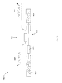
- FIG. 10 is a schematic diagram illustrating a standing wave laser with a modulated output coupler, according to embodiments of the present invention.
- FIG. 11 is a schematic diagram illustrating an alternative embodiment of the laser shown in FIG. 10 in which the gain medium is housed in a reflector.
- FIG. 12 is a schematic diagram illustrating an alternative embodiment of the laser shown in FIG. 10 that includes a directional coupler.
- FIG. 13 is a schematic diagram illustrating an alternative embodiment of the laser shown in FIG. 10 that includes a directional coupler.
- FIG. 14 is a schematic diagram illustrating an alternative embodiment of the laser shown in FIG. 10 that includes a directional coupler and in which the gain medium is housed in a reflector.
- the laser 20 includes an optical resonator 22 that defines a circulation path for light confined within the optical resonator 22 . It should be understood that confinement of light could be provided in the optical resonator 22 according to different mechanisms, for example by a boundary between a higher refractive index material and a lower refractive index material.
- a gain medium 25 housed inside the optical resonator 22 is pumped with a suitable excitation source, such as pump 26 .
- the gain medium 25 can be made from any suitable optically amplifying material and, without limitation, can be made from a solid, a liquid, a gas, or plasma.
- the gain medium 25 can comprise suitable semiconductor materials.
- the pump 26 can be configured to deliver different forms of energy to the gain medium 25 .
- the pump 26 can be configured to deliver electrical energy (e.g. an applied voltage), optical energy (including either laser light or incoherent light), or any other suitable energy form as the skilled person would appreciate.
- electrical energy e.g. an applied voltage
- optical energy including either laser light or incoherent light
- optical resonator should be understood to include optical cavities.
- Light of a characteristic wavelength passing through the gain medium 25 is coherently amplified through stimulated emission.
- the gain medium 25 is pumped to and above a laser threshold of the optical resonator 22 , light circulating in the optical resonator 22 reaches laser oscillation and the laser 20 outputs a coherent light wave.
- the balance between the gain saturation of the gain medium 25 and the excitation energy delivered by the pump 26 produces a steady-state power inside the optical resonator 22 ; this steady-state power determines the operating point of the laser 20 and is selectable by controlling the output of the pump 26 .
- the laser 20 also includes an output coupler 28 that allows a portion of the light circulating within the optical resonator 22 to exit.
- the output coupler 28 is a passive (i.e. not actively controlled) element, such as a partially transparent mirror. Most of the light striking the surface of the mirror is reflected back into the optical resonator 22 , while a small fraction of the light (perhaps ⁇ 1-5% of the internal steady-state power) transmits through the mirror and becomes the laser output signal 30 .
- the output coupler 28 would not be directly controlled. To modulate the output signal 30 would require active control over some other system component. For example, as the skilled person will appreciate, direct pump-modulation and external modulation schemes may be employed.
- the laser 20 could also be operated in a mode-locked or Q-switched configuration to provide variable laser output.
- a modulated output coupler included in the optical resonator 22 can be used to achieve pseudo-direct modulation of the laser output signal 30 .
- Such arrangement can confer significant advantages over these other modulation schemes in terms of available operating bandwidth, signal distortion (e.g., chirp), power efficiency, and size.
- FIG. 2 schematically illustrates a pump-modulated laser.
- the laser 120 is similar to the laser 20 shown in FIG. 1 , but controller 132 generating a control signal 134 for the pump 126 is also included.
- the controller 132 can be integrated within the laser 120 or provided as a separate circuit as the case may be.
- the control signal 134 determines the rate and magnitude of the pump excitation signal 136 delivered to the gain medium 125 .
- the gain medium 125 is housed inside an optical resonator 122 , and the laser output signal 130 is allowed by the output coupler 128 to exit the optical resonator 122 .
- the response of the gain medium 125 to the varying excitation signal 136 causes a controllable variation in the amount of power circulating in the optical resonator 122 , which is then passively coupled through the output coupler 128 to generate a modulated output signal 130 .
- the modulated output signal 130 inherits the modulation response of the gain medium 125 due to the direct pump modulation.
- the useful range of operation of the pump-modulated laser 120 is limited by, among other things, the physical properties of the optical resonator 122 and gain medium 125 .
- the laser 120 is characterized by its relaxation resonance frequency, which for semiconductors is approximately
- ⁇ R AP 0 ⁇ p , ( 1 )
- A represents the differential gain constant of the gain medium 125
- P 0 represents steady-state photon density within the optical resonator 122
- ⁇ p represents photon lifetime within the optical resonator 122 .
- the relaxation resonance frequency ⁇ R provides a measure of how fast the gain medium 125 can respond to variations of the internal circulating power and vice-versa. In practical terms, the relaxation resonance frequency ⁇ R sets an effective upper limit on the modulation rate of the pump 126 before the response of the modulated output signal 130 will be too distorted and/or too small to encode a transmission data signal.
- FIG. 3 shows a graph of an exemplary small signal modulation response of the pump-modulated laser 120 shown in FIG. 2 .
- the graph 140 plots modulation frequency (in GHZ) on the x-axis against modulation response (in dB) on the y-axis. It should be understood that the graph 140 is but one exemplary modulation response of a pump-modulated laser 120 , and that different pump-modulation configurations could produce different responses. No numerical range or feature of the graph 140 is limiting.
- Curve 142 includes a generally flat region 144 over a range of low modulation frequencies, in which the modulation response of the optical resonator 122 shows a large response to the modulation signal and no appreciable dependence on modulation frequency. Within this low frequency range, modulating the excitation energy signal 136 produces corresponding variations in the intra-cavity field strength of the optical resonator 122 , which are then passively coupled out of the optical resonator 122 to generate the modulated output signal 130 .
- Generally flat region 144 can therefore represent the useful operating region of the pump-modulated laser 120 .
- the modulation response exhibits a dependence on modulation frequency once curve 142 enters into the roll-off region 146 .
- the modulation response to variations in the excitation energy signal 136 begins to diminish for larger modulation frequencies in the frequency range defined by roll-off region 146 .
- the gain medium 125 is no longer able to respond quickly enough to the variations in the excitation energy signal 136 .
- the modulated output signal 130 no longer inherits the modulation response to variations in the excitation energy signal 136 .
- the transition point between the generally flat region 144 and roll-off region 146 is the relaxation resonance frequency ⁇ R of the optical resonator 122 , indicated by a knee-point 148 in curve 142 .
- relaxation resonance frequency ⁇ R represents an effective upper frequency limit for the modulation rate of the pump-modulated laser 120 .
- the relaxation resonance frequency ⁇ R is dictated largely by the physical properties of the optical resonator 122 , gain medium 125 , and operation bias of the laser 120 .
- these techniques include engineering of the quantum confinement in the active medium, utilizing injection locking techniques, and leveraging cavity quantum electrodynamics effects.
- relaxation resonance frequency ⁇ R tends to be inversely related to the resonator quality factor (“Q factor”), as suggested in Eq. 1, increasing the relaxation resonance frequency ⁇ R often decreases the Q factor by a corresponding amount.
- Q factor resonator quality factor
- Direct-pump modulation of the laser 120 can also suffer unavoidably from chirp in the modulated optical signal 130 .
- both the gain and refractive index of the gain medium 125 inside the optical resonator 122 will vary in response.
- unwanted phase shifts or “chirp”
- chirp represents another potentially significant limitation on the utility of direct pump-modulation schemes.
- the laser 220 is similar to the laser 20 but includes external modulator 250 responsive to a control signal 254 generated by controller 252 .
- pump 226 delivers relatively constant excitation energy to the gain medium 225 , thereby maintaining a relatively constant, steady-state power circulating internally within the optical resonator 222 .
- Output coupler 228 may again be a passive element, but this time providing a continuous-wave (CW) optical signal 256 to the external modulator 250 for amplitude and/or phase modulation.
- CW continuous-wave
- external modulator 250 transforms the CW optical signal 256 into the modulated output signal 230 .
- external modulator 250 can comprise one or more variable switches, for example based on Mach-Zehnder Interferometers (MZI) or electro-absorption modulators, which are configurable by the control signal 254 to modulate the CW optical signal 256 .
- the external modulator 250 can provide one or more of gain, absorption, constructive interference, or destructive interference of the CW optical signal 256 to achieve modulation.
- the modulated output signal 230 can optically encode a transmission data signal according to one or more different modulation schemes.
- the external modulator 250 overcomes some of the limitations inherent to the pump-modulated laser 120 as described herein. For example, configuring an MZI in the external modulator 250 for push-pull operation can produce modulated output that is ideally free of chirp. Quadrature amplitude modulation (QAM), involving simultaneous modulation of both amplitude and phase, can also be realized by including a nested MZI in each arm of the MZI in the external modulator 250 . The modulation rate of the external modulator 250 can also greatly exceed the relaxation resonance frequency ⁇ R of the laser 220 . These various considerations make the external modulator 250 suitable for use in high data rate optical transmission links.
- QAM Quadrature amplitude modulation
- the modulator 250 will tend to require relatively large amplitude input drive.
- the power of the CW optical signal 256 already represents a significant reduction of the internal steady-state power of the optical resonator 222 due to the low transmission coefficient of the output coupler 228 .
- the output optical power from the laser 220 i.e. the power of the CW optical signal 256
- the modulated optical signal 230 will be transmitted error-free over the transmission link.
- large differential phase delays or alternatively gains/absorptions
- modulation of the laser output coupler rather than an external switch, such as modulator 250 leverages the comparatively large internal power circulating in the optical resonator 222 to achieve significant efficiency gains in the modulation, while at the same time retaining a large modulation bandwidth and enabling amplitude-phase modulation of the modulated output signal 230 .
- high-finesse micron-scale resonators can also be used, which additionally provides an increased free spectral range (FSR).
- FIG. 5 shows a schematic representation of a ring laser incorporating a modulated output coupler in accordance with embodiments of the present invention.
- the laser 320 comprises an optical resonator 322 defining a confinement path for light to circulate therewithin, a pump 326 and a modulated output coupler 360 .
- a gain medium 325 is housed inside the optical resonator 322 and situated in the path of the laser light circulating within the optical resonator 322 . As illustrated in FIG.
- opposite ends of the output coupler 360 may be optically coupled to corresponding opposite ends of the ring structure 358 to define a circular confinement path in the optical resonator 322 , such that each of the ring structure 358 and the output coupler 360 provides a portion of the optical resonator 322 .
- the connections between the output coupler 360 and ring structure 358 provide optical coupling therebetween, defining a ring geometry for the optical resonator 322 , i.e. a ring resonator.
- the output coupler 360 can be formed monolithically on a semiconductor die. Alternatively, the output coupler 360 can be integrated heterogeneously with the ring structure 358 within the optical resonator 322 .
- the optical resonator 322 can also be a high-finesse, micron-scale resonator in some embodiments. For example, the optical resonator 322 can be micron or millimeter scale.
- the gain medium 325 housed in the optical resonator 322 enables laser operation.
- Pump 326 delivers excitation energy to the gain medium 325 above the laser threshold to achieve coherent oscillation in the optical resonator 322 and generate laser output.
- the optical resonator 322 formed, in part, by the ring structure 358 and the output coupler 360 provides a continuous path for the laser light confined within the optical resonator 322 to circulate.
- laser light circulates in the optical resonator 322 in a traveling wave manner.
- the output coupler 360 is included in the optical resonator 322 in the path of the circulating wave of laser light and is responsive to control signal 364 generated by the controller 362 .
- Light received from the ring structure 358 into the output coupler 360 is either coupled to the laser output or back into the ring structure 358 in response to the control signal 364 .
- a portion of the circulating light is selectively allowed by the output coupler 360 to exit from the optical resonator 322 as the modulated output signal 330 .
- Light received into the output coupler 360 but not emitted from the optical resonator 322 is retained in the optical resonator 322 where it continues to circulate.
- the output coupler 360 can be a variable coupler that is selectively configurable by the control signal 364 to modulate the output signal 330 .
- the output signal 330 can be modulated in one or both of amplitude and phase, and according to simple or more advanced modulation schemes.
- This enables the laser 320 to operate by applying both Phase-Shift Keying (PSK) and Quadrature Amplitude Modulation (QAM) schemes to the modulated output signal 330 .
- PSK Phase-Shift Keying
- QAM Quadrature Amplitude Modulation
- other modulation schemes may be applied as well, including for example Amplitude-Shift Keying (ASK) and simple amplitude modulation. This list of schemes is not understood to be limiting.
- FIG. 6 schematically illustrates the output coupler 360 shown in FIG. 5 in greater detail.
- An input port 370 of the coupler 360 is connected and optically coupled to the corresponding first end of the ring structure 358 adjacent the input port 370 , and provides a low loss interface for light to be received therefrom into the output coupler 360 .
- the output coupler 360 also includes an output-coupled port 372 from which the modulated optical signal 330 is emitted, for example to a downstream optical communication link, such as an optical fiber.
- a through port 374 of the output coupler 360 is also connected and optically coupled to a corresponding opposite end of the ring structure 358 adjacent the through port 374 , and provides another low loss interface for light to be transmitted back thereto.
- the input port 370 feeds an interference section 376 , the downstream end of which is optically coupled with both the output-coupled and through ports 372 , 374 .
- the interference section 376 of the output coupler 360 can be formed integrally within the optical resonator 322 , as opposed to being provided externally to the optical resonator 322 (as may be the case in external modulation schemes).
- the control signal 364 generated by the controller 362 and provided to the output coupler 360 configures the interference section 376 so that the input optical power received at the input port 370 is apportioned between the output-coupled and through ports 372 , 374 .
- the circulating power inside the optical resonator is proportional to
- the input power P in (t) will be conserved between the output-coupled and through ports 372 , 374 , such that
- 2 1, (3)
- the absolute value squared represents power.
- the signal provided to the through port 374 can be complementary to the modulated output signal 330 emitted from the output-coupled port 372 .
- the relationship specified in Eq. 3 can also be modified depending on whether the output coupler 360 is lossy or has net gain. In the lossy case, the left side of Eq. 3 can sum to a value less than 1. In the case of net gain, it can sum to a value greater than 1.
- the pump 326 can be configured to deliver excitation energy to the gain medium 325 to maintain a quasi-constant amplitude of the circulating field.
- the excitation energy delivered to the gain medium 325 can be dc excitation energy, but can also have a time-varying compensation component as described below.
- the modulation rate of the output coupler 360 can be selected to be much greater than the relaxation resonance frequency ⁇ R of the optical resonator 322 .
- the photon density within the optical resonator 322 will no longer be able to respond to changes in its operating conditions, and thus will remain largely unaffected by small changes in the output-coupling coefficient ⁇ (t).
- large changes in the output-coupling ⁇ (t) could disturb the internally circulating field from its approximately steady-state value.
- the internally circulating field within the optical resonator 322 remains essentially at E in,0 and essentially undisturbed by modulation of the output coupler 360 . Under these conditions, the modulation response of the laser can be decoupled from the intrinsic response of the optical resonator 322 due to interactions between the circulating laser light and the gain medium 325 .
- the amplitude of the internally circulating field can be held relatively constant (or “quasi-constant”), with only minor fluctuations around a selected, steady-state level.
- the internally circulating field is ideally maintained at a selected, steady-state amplitude E in,0 .
- the pump 326 delivers dc excitation energy to the gain medium 325 .
- the pump 326 can optionally be controlled to provide time-varying excitation energy to compensate for some of the fluctuations in the internally circulating field in the optical resonator 322 . But even in this case, complete stabilization may not be possible.
- some fluctuation within an operable range defined around the desired steady-state value may be tolerable, which can be about 5%, but perhaps even as much as 20%, of the desired steady-state value in some cases.
- the exact size of the operable range may depend upon the physical parameters of the optical resonator 322 as well as characteristics of the downstream optical transmission link.
- the specified range can be small enough so that fluctuation of the internally circulating field around the desired steady-state value is not so large that the resulting distortion in the modulated optical signal 330 exceeds tolerances specified for the transmission link. Different tolerances for different transmission links can suggest different specified ranges.
- the fluctuation of the internally circulating field in the optical resonator 322 should also not be so large that the optical resonator 322 experiences laser turn-on/off dynamics.
- the output-coupling coefficient ⁇ (t) can be selected so that changes in its amplitude are small enough to maintain the internally circulating field within an operable range around a desired steady-state value in which the distortion effects herein described are avoided.
- the selected modulation rate and desired steady-state power can also influence how much amplitude change in the output-coupling coefficient ⁇ (t) will be acceptable.
- the range of modulation frequencies over which distortion in the modulated output signal 330 is significant can also be minimized by reducing ⁇ R and by reducing the magnitude of the changes in the output-coupling coefficient ⁇ (t).
- the relaxation resonance frequency ⁇ R tends to be related inversely to the resonator Q factor.
- Q factor often will be sacrificed for higher modulation rates in pump-modulated laser applications, the opposite holds true for the coupler modulated laser 320 .
- the optical resonator 322 can be designed to maximize its Q factor and thereby to also reduce distortions in the modulated output signal 330 by reducing the relaxation resonance frequency ⁇ R .
- Resonator finesse is another commonly utilized performance metric for optical resonators.
- finesse provides a combined indication of expected loss in the resonator (similar to the Q factor) and resonator free spectral range (FSR), which is defined as the frequency difference between the resonator centre frequency and the nearest resonance modes.
- FSR resonator free spectral range
- the optical resonator 322 is a micro-resonator formed monolithically with the modulated output coupler 360 on a semiconductor die. As mentioned, micron or millimeter sized resonators are suitable, for example.
- Small high-Q, i.e. high finesse, resonators also have the benefit of exhibiting comparatively large internally circulating power
- 2 The magnitude of the output-coupling coefficient ⁇ (t) to optimize the laser output power also decreases with increasing finesse.
- the output coupler 360 leverages the large amplitude of the internal field E in,0 circulating in optical resonator 322 to enable only a very small output-coupling coefficient ⁇ (t), and small changes thereof, to generate the modulated output signal 330 at sufficient transmission power levels.
- the pump 326 can be configured to deliver an excitation signal to the gain medium 325 that maintains a quasi-constant amplitude of the circulating field, and the output coupler 360 can be modulated at modulation rates well in excess of the relaxation resonance frequency ⁇ R , to maintain a relatively constant power P in,0 circulating internally in the optical resonator 322 .
- the output coupler 360 can also be designed and operated such that the modulated output signal 330 will be chirp free or at least have controllable chirp.
- the output coupler 360 is also configurable for implementing many common data modulation schemes, as will now be described in more detail.
- a modulated output coupler 360 ′ which is suitable for implementing any of an amplitude, binary phase-shift keying (BPSK), and differential phase-shift keying (DPSK) modulation scheme.
- An MZI 380 included in output coupler 360 ′ is optically coupled at one end to the input port 370 , and comprises a top branch 381 and bottom branch 382 .
- top branch and bottom branch are used only for convenience of reference to FIG. 7 and are not intended to be limiting.
- the relative positioning of the top and bottom branches 381 , 382 could be reversed without affecting the operation of the output coupler 360 ′. Equally these elements could be referred to simply as first and second branches.
- An optical field splitter at the input port 370 splits the incident light between the top branch 381 and the bottom branch 382 .
- the optical field splitter can be a directional coupler, a cross-switch coupler, a multi-mode interference coupler, a y-junction, or some other suitable type of coupler.
- the energy splitting between the top and bottom branches 381 , 382 can be equal (as in the case of an appropriately designed y-junction, for example), but can also be arbitrary.
- the optical field splitter can couple light to the top and bottom branches 381 , 382 in phase, but can also impose a relative phase shift between the light coupled to the top branch 381 and the light coupled to bottom branch 382 .
- the top and bottom branches 381 , 382 are also optically coupled to a coupler 383 at an opposite end of the MZI 380 .
- the coupler 383 can be a 3 dB coupler having four distinct ports, including a first input port 384 coupled to the top branch 381 , a second input port 385 coupled to the bottom branch 382 , as well as a first output port 386 and a second output port 387 , which are coupled respectively to the output-coupled port 372 and the through port 374 of the output coupler 360 ′.
- the coupler 383 can be a directional coupler, a cross-switch coupler, a multi-mode interference coupler, or some other suitable type of coupler.
- PSK is a digital modulation scheme that encodes data by controlling (i.e. modulating) the phase of a reference carrier signal.
- PSK will map unique binary patterns to corresponding discrete phases in the reference carrier signal.
- the encoded binary patterns can be reconstructed at the receiver end of the optical transmission link.
- the set of discrete phases will be evenly distributed over the range (0,2 ⁇ ).
- BPSK Binary Phase-Shift Keying
- phase-shift keying can be implemented in the modulated output coupler 360 ′.
- the MZI 380 and coupler 383 can be included in the interference section 376 of the modulated output coupler 360 ′.
- Light received into the MZI 380 from the input port 370 splits between the top and bottom branches 381 , 382 .
- part of the power input to the MZI 380 is directed to the top branch 381 and part of the input power is directed to the bottom branch 382 .
- Power splitting may be equal between the top branch 381 and bottom branch 382 , though it can also be unequal as will be appreciated.
- the respective phase shifts experienced by optical signals through the top and bottom branches 381 , 382 are independently controllable using the control signal 364 .
- control signal 364 comprises voltages applied to materials housed in the branches 381 , 382 whose refractive indices change in response to the applied voltage. Controlling the amplitude of the applied voltage thereby controls the effective optical path length of each respective branch 381 , 382 and allows for optical signals of generally different phases to be coupled together in coupler 383 to provide controlled optical interference.
- controllably varying refractive index in the top and bottom branches 381 , 382 to provide output modulation it is also possible instead to controllably vary gain and/or attenuation (“gain/attenuation”) in the top and bottom branches 381 , 382 .
- the control signal 364 comprises voltages applied to materials housed in the top and bottom branches 381 , 382 , only now whose gain/attenuation change in response to the applied voltage.
- optical signals of generally different amplitude can be coupled together in coupler 383 to provide controlled optical interference.
- Control over one or more of refractive index and gain/attenuation in the interference section 376 using the control signal 364 is possible according to embodiments of the present invention. Control over other operating characteristics of the interference section 376 may also be possible to the same effect.
- the top branch 381 and bottom branch 382 are coupled respectively to the first and second input ports 384 , 385 of the coupler 383 , wherein signals transmitted through these branches are optically interfered.
- the interference can be destructive or constructive, but also partially destructive if desired.
- the coupler 383 will cross-couple the optically interfered signal to the output-coupled port 372 and, according to Eq. 3, a signal complementary to the optically interfered signal to the through port 374 .
- a lossless coupler 360 ′ light which is not emitted from the output-coupled port 372 will be routed to the through port 374 and thereby retained within the optical resonator 322 .
- the coupler 383 can realize the different output-coupling coefficients ⁇ (t) required to generate the modulated output signal 330 at the output-coupled port 372 .
- Complementary through-coupling coefficients ⁇ (t) can also be realized at the through-coupled port 374 for retaining laser light within the optical resonator 322 to continue circulating.
- Simple amplitude modulation can be achieved in the output coupler 360 ′ by biasing the MZI 380 so that the modulated output signal 330 emitted from the output-coupled port 372 has an initially non-zero amplitude, and so that the modulated output signal 330 is not significantly phase-shifted upon modulation.
- the non-zero amplitude of the modulated output signal 330 can represent some fractional part of the internally circulating power in the optical resonator 322 .
- the power from the input port 370 can be split equally between the top and bottom branches 381 , 382 , and the top and bottom branches 381 , 382 can be controlled by the control signal 364 to provide equal but opposite phase shifts, respectively, of
- the top and bottom branches 381 , 382 can act as phase-advance and phase-delay branches. This is sometimes referred to as push-pull operation.
- Amplitude modulation can be achieved by time-varying the size of the incremental phase-shift ⁇ (t) around the bias point of the MZI 380 . Thereby the output coupler 360 will selectively emit more or less laser light from the optical resonator 322 .
- the controlled incremental phase-shift ⁇ (t) represents, or is at least relatable to, the encoded data signal.
- simple amplitude modulation can be applied to the modulated output signal 330 , can also be achieved, by controllably varying the respective gain/attenuation of the top and bottom branches 381 , 382 around the bias point of the MZI 380 .
- the MZI 380 is biased for zero transmission to the output-coupled port 372 .
- the top and bottom branches 381 , 382 are again controlled by the control signal 364 in push-pull configuration to phase-shifts of
- the top branch 381 can provide the phase-delay and the bottom branch 382 the phase advance.
- modulation of the incremental phase shift ⁇ (t) around the bias point drives the MZI 380 through its maximum extinction point, and thereby produces a controllable phase shift in the output modulated signal 330 of either 0 or ⁇ , as required for BPSK or DPSK.
- the optical field splitter between the input port 370 and the top and bottom branches 381 , 382 is a y-junction. It is assumed that the optical splitter provides equal power splitting between the top and bottom branches 381 , 382 , and additionally imposes no phase shift between light coupled to the top branch and the bottom branch. It is also assumed for illustrative purposes only that the coupler 383 provides equal cross-coupling and through-coupling of optical power, and additionally imposes a
- phase shift between through-coupled and cross-coupled light As will be understood, the term through-coupling describes the amount of light incident at input port 384 that is coupled to output port 386 , and likewise between input port 385 and output port 387 .
- the term output-coupling similarly describes the amount of light incident at input port 384 that is coupled to output port 387 , and likewise between input port 385 and output port 386 . This coupling is typical of a 3-dB directional coupler. In this illustrative case, phase shifts of
- ⁇ ⁇ 4 can be applied to the top and bottom branches 381 , 382 to set the zero transmission bias point of the MZI 380 , thereby resulting in total phase-shifts of
- the amount of the resulting phase shift, 0 or ⁇ , in the output modulated signal 330 is controllable depending on the polarity of the incremental phase shift ⁇ (t) in the MZI 380 .
- Eq. 4a assumes lossless operation of the output coupler 360 ′. Accordingly, as will be appreciated, these expressions for ⁇ (t) and ⁇ (t) may only be approximate and not general expressions. Of course, the exact form of Eq. 4a may differ for other configurations or assumptions made of the output coupler 360 ′.
- the output modulated coupler 360 ′ is able to realize large efficiency gains over the external modulator 250 .
- the external modulator 250 requires comparatively much larger phase shifts (and thus also input drive amplitude) to achieve the same phase inversion for BPSK with a comparable output amplitude.
- the powers savings realized by the output coupler 360 ′ can be as high as 2 or 3 orders of magnitude.
- the output coupler 360 ′′ comprises first MZI 400 , first coupler 401 , second MZI 402 , and second coupler 403 .
- First and second couplers 401 , 403 can be 3 dB couplers.
- the first MZI 400 is optically coupled at one end to the input port 370 to receive circulating light into the output coupler 360 ′′.
- Top branch 404 and bottom branch 405 of the first MZI 400 couple into respective input ports of the first coupler 401 .
- first output port 406 and second output port 407 of the first coupler 401 respectively couple into a top branch 408 and bottom branch 409 of the second MZI 402 .
- the top and bottom branches 408 , 409 couple into respective input ports of the second coupler 403 .
- the output-coupled port 372 of the output coupler 360 ′′ is coupled to the first output port 410 of the second coupler 403 , while the through port 374 is coupled to the second output port 411 .
- top branch and “bottom branch” are again used for convenient reference to FIG. 8 only. As with FIG.
- one or both of the first and second couplers 401 , 403 can be a directional coupler, a cross-switched coupler, a multi-mode interference coupler, or some other suitable coupler.
- the arrangement of MZIs 400 , 402 and couplers 401 , 403 in the interference section 376 is configurable for applying QAM to the modulated output signal 330 .
- the top and bottom branches in the first and second MZIs 400 , 402 are controllable, through proper calculation of the control signal 364 , to provide respective phase shifts that apply QAM to the modulated output signal 330 .
- the first MZI 400 is controllable to provide a phase-advance
- the second MZI 402 is similarly controllable to provide a phase-advance
- the modulated optical signal 330 emitted from the output-coupled port 372 will comprise both in-phase and quadrature modulated signal components as required in QAM.
- a signal complementary to the modulated output signal 330 will be directed to the through port 374 for internal circulation within the optical resonator 322 , as seen before.
- QAM (either analog or digital) imparts information (in the form of a transmission data signal) onto both the amplitude and phase of the modulated optical signal 330 , implying that the modulated output signal 330 should have arbitrary and controllable magnitude and phase.
- This condition is met in the output coupler 360 ′′ when two optical signals of different amplitudes are provided to the second MZI 402 , wherein they are subjected to a differential phase shift and then coupled to the output-coupled port 372 ; the combination of the first MZI 400 and the first coupler 401 can be configured to generate the necessary different amplitude optical signals.
- the top branch 404 is controlled through the control signal 364 to provide an incremental phase-advance of
- the size of the incremental phase shift ⁇ 1 determines the splitting ratio between the two signals appearing at the output ports 406 , 407 that couple the second MZI 402 .
- the control signal 364 moreover controls the top branch 408 to provide an incremental phase-advance of
- both the first MZI 400 and second MZI 402 can be operated in push-pull configuration as well.
- the signal directed by the second coupler 403 to the output-coupled port 372 i.e. the modulated output signal 330 , is then a summation of the two different amplitude signals generated by the first coupler 401 and phase-shifted in the second MZI 402 .
- extra phase shifts are applied to the output coupler 360 ′′ for a small output-coupling coefficient ⁇ (t) relative to the internally circulating field E in,0 , as is desirable for high Q or high finesse optical resonators.
- the configuration of the modulated output coupler 360 ′′ shown in FIG. 8 will generate both an in-phase and quadrature component in the modulated output signal 330 as required for QAM.
- the optical field splitter between the input port 370 and the top and bottom branches 404 , 405 provides equal power splitting between the top and bottom branches 404 , 405 , and additionally imposes no phase shift between light coupled to the top branch 404 and the bottom branch 405 , which is typical of an appropriately designed y-junction.
- each of the couplers 401 , 403 provide cross-coupling and through-coupling, as described above, which again is typical of 3-dB directional couplers.
- ⁇ (t) extra phase shifts of
- ⁇ ⁇ 2 can be applied to the top and bottom branches 404 , 405 , respectively, together with extra phase shifts of
- the modulated output coupler 360 ′′ can be shown to achieve output-coupling and through-coupling coefficients given by
- FIG. 9 is a schematic diagram illustrating an alternative embodiment of the coupler modulated laser 320 shown in FIG. 5 that is wavelength tunable.
- the coupler modulated laser 420 comprises optical resonator 422 implemented with the output coupler 360 ′ of FIG. 7 , although it should be appreciated that the output coupler of 360 ′′ of FIG. 8 could be included instead.
- Gain medium 425 is housed inside the optical resonator 422 and supplied with excitation energy from a suitable pump (not shown).
- the coupler modulated laser 420 further comprises wavelength tuning section 429 included in the path of the laser light circulating internally within the optical resonator 422 .
- the wavelength tuning section 429 In response to a wavelength tuning control signal provided by a wavelength controller (not shown), the wavelength tuning section 429 selectively adjusts a refractive index of the optical resonator 422 , thereby altering the resonant wavelengths of the optical resonator 422 . Accordingly, the wavelength of the modulated output signal 330 can be tuned.
- the wavelength of the modulated output signal 330 can depend on other physical properties of the optical resonator 422 as well, and that the degree of tuning possible may be limited. For larger variations in wavelength, therefore, it may be necessary to adjust or otherwise reconfigure the optical resonator 422 .
- FIG. 10 is a schematic diagram illustrating a standing wave laser incorporating a modulated output coupler in accordance with embodiments of the present invention.
- the coupler modulated laser 520 comprises the output coupler 360 ′ included in the optical resonator 522 .
- the output coupler 360 ′′ could be included instead.
- a first reflector 521 which can be a distributed feedback (DFB) grating or a Bragg reflector, for example, is optically coupled to the input port 370 of the output coupler 360 ′.
- a second reflector 523 is optically coupled to the through port 374 of the output coupler 360 ′.
- DFB distributed feedback
- One or both of reflectors 521 , 523 can be tunable with a tunable reflection spectrum.
- gain medium 525 can be housed within the optical resonator 522 , which defines a confinement path for the light circulating therein.
- the gain medium 525 can be housed in one or both of the reflectors 521 , 523 .
- the reflectors 521 , 523 can also be tunable to control the wavelength of the modulated output signal 330 by affecting an amount of optical feedback in the optical resonator 522 .
- the modulated output coupler 360 ′ in the laser 520 can otherwise function as described herein.
- FIG. 11 is a schematic diagram illustrating an alternative embodiment of the coupler modulated laser 520 shown in FIG. 10 .
- the coupler modulated laser 620 comprises output coupler 360 ′′′ included in optical resonator 622 .
- the output coupler 360 ′′′ is similar to the output coupler 360 ′ but includes a corresponding input port for each of the top branch 381 and bottom branch 382 .
- a first reflector 621 e.g. a DFB grating or Bragg reflector
- a second reflector 623 is optically coupled to a through port of the output coupler 360 ′′′.
- a third reflector 625 is also optically coupled to the bottom branch input port.
- One or more of the reflectors 621 , 623 , 625 can be tunable with a tunable reflection spectrum.
- the output coupler 360 ′′ and the reflectors 621 , 623 and 625 can all be formed in the optical resonator 622 .
- the gain medium for the optical resonator 622 is housed in the reflector 625 , but could alternatively be housed in any or all of the reflectors 621 , 623 , 625 .
- reflections in the reflectors 621 , 623 , 625 create a standing wave pattern in the optical resonator 622 . Controlling the output coupler 360 ′′′ using the control signal 364 will therefore generate the modulated optical signal 330 , substantially as described herein.
- FIG. 12 is a schematic diagram illustrating an alternative embodiment of the coupler modulated laser 420 shown in FIG. 9 in which the output coupler includes a directional coupler.
- the coupler modulated laser 720 comprises optical resonator 722 implemented in this case using a directional coupler 760 , or perhaps a cross-switch coupler, instead of a combination MZI-3 dB coupler.
- Gain medium 725 is housed inside the optical resonator 722 in the path of the circulating light and is supplied with excitation energy from a suitable pump (not shown).
- the optical resonator 722 further includes optional wavelength tuning section 729 , which is also included in the path of the circulating laser light.
- control signal 364 By application of the control signal 364 to the directional coupler 760 , laser light circulating in the optical resonator 722 is controllably coupled into the directional coupler 760 , wherein through modulation of the output coupler 760 , the output coupled light exits the directional coupler 760 as the modulated optical signal 330 .
- a different control signal 364 can be required to modulate the output coupler 760 , as compared to the control signal used to modulated output coupler 360 ′. Otherwise the output coupler 760 can function substantially according to embodiments of the invention described herein.
- FIG. 13 is a schematic diagram illustrating an alternative embodiment of the coupler modulated laser 520 shown in FIG. 10 that includes a directional coupler.
- the coupler modulated laser 820 comprises directional coupler 760 instead of a combination MZI-3 dB coupler.
- a first reflector 821 (again e.g. a DFB grating or Bragg reflector) is optically coupled to a second reflector 823 .
- Reflectors 821 , 823 can again be tunable with a wavelength tunable reflection spectrum.
- the first reflector 821 and second reflector 823 can provide terminal reflection points for the optical resonator 822 in which gain medium 825 is again housed in a waveguide defined therein and supplied with excitation energy.
- the reflectors 821 , 823 can be wavelength tunable and can house the gain medium 825 .
- Light circulating in the optical resonator 822 will form a standing wave pattern between the two reflectors 821 , 823 , some of which is controllably coupled into the directional coupler 760 .
- the control signal 364 can be applied to control an operating characteristic of the directional coupler 760 , such as its refractive index, to selectively couple light energy.
- the directional coupler 760 is a 4-port device, if desired, modulated output signal 330 ′ can be emitted from one end of the directional coupler 760 , while a second modulated signal 330 ′′ can be emitted from an opposite end thereof. Alternatively, only one modulated output signal can be generated. Otherwise the output coupler 760 can function substantially accordingly to embodiments of the invention described herein.
- FIG. 14 is a schematic diagram illustrating an alternative embodiment of the coupler modulated laser 520 shown in FIG. 10 that includes a directional coupler and in which the gain medium is housed in a reflector or waveguide.
- the coupler modulated laser 920 comprises the directional coupler 760 instead of a combination MZI-3 dB coupler.
- a first reflector 921 e.g. a DFB grating
- the gain medium is illustrated as being housed in the reflector 925 , though it could be housed in a waveguide defined in the optical resonator 922 instead.
- the first reflector 921 and second reflector 925 can provide terminal reflection points for the optical resonator 922 , as well as wavelength tuning for the modulated output signal 330 .
- Light circulating in the optical resonator 922 will form a standing wave pattern between the two reflectors 921 , 932 .
- a suitable control signal 364 By locating the directional coupler 760 in close proximity to the second reflector 925 , and in response to application of a suitable control signal 364 , some of the light reflected in the reflector 925 can be controllably coupled into the directional coupler 760 . Again the control signal 364 can be applied to control an operating characteristic of the directional coupler 760 , such as its refractive index.
- modulated output signal 330 ′ can be emitted from one end of the directional coupler 760 , while a second modulated signal 330 ′′ can be emitted from an opposite end thereof.
- only one output can be provided. Otherwise the output coupler 760 can function substantially according to embodiments of the invention described herein.
- the modulated output coupler can be suitable for operation with many different configurations of lasers.
- the detailed description of embodiments presented herein is intended to be illustrative of the invention, the scope of which is limited only by the language of the claims appended hereto.
Abstract
Description
where A represents the differential gain constant of the
to the CW
E out(t)=κ(t)·E in(t), (2)
where κ(t) represents a coupling coefficient between the
|κ(t)|2+|σ(t)|2=1, (3)
where σ(t) represents a coupling coefficient between the
can be quite significant.
can be used to encode two-bit binary patterns (00, 01, 10, 11), and is sometimes called Quaternary Phase-Shift Keying (QPSK). Limited perhaps only by the signal-to-range ratios of practical optical communication systems, any number of discrete phases can be mapped to different bit patterns. Increasing the order of the encoded bit patterns by specifying larger phase sets can increase the data rate of information encoded through phase-shift keying because each phase shift can represent a longer bit sequence. In other instances, instead of mapping discrete phases to bit patterns, differences in phase shift can be mapped to different bit patterns. Thus, in this type of differential PSK, a certain change in the phase shift represents a corresponding bit pattern. Either type of phase-shift keying can be implemented in the modulated
applied to the bias point of the
respectively, about the zero transmission bias point. It should be appreciated that the reverse configuration is possible as well, in which the
incremental phase-shifts, depending on the specific implementation of the
phase shift between through-coupled and cross-coupled light. As will be understood, the term through-coupling describes the amount of light incident at
can be applied to the top and
respectively. Under these conditions, the amount of the resulting phase shift, 0 or π, in the output modulated
which through satisfaction of Eq. 3 are indeed complementary expressions. It is noted that Eq. 4a assumes lossless operation of the
using the well known approximation of the sine function for small arguments. It is at least in part due to the small incremental phase shifts capable of providing BPSK or DPSK that the output modulated
in the
in the
in the
in the
while the
The size of the incremental phase shift Δθ1 determines the splitting ratio between the two signals appearing at the
and the
Thus, both the
incremental phase-shifts, which depend on the specific implementation of the
can be applied to the top and
applied to the top and
in the
where again κ(t) represents the coefficient of output-coupling, σ(t) represents the coefficient of through-coupling, and from Eq. 3, κ(t) is complementary to σ(t). For small angles Δθ1(t) and ΔθQ(t), again the expression for the output-coupling coefficient κ(t) can be simplified to
which is perhaps a more useful form. It is apparent from Eq. 5b that variation of Δθ1(t) and ΔθQ(t) allows for arbitrary and controllable modulation of the real and imaginary components of κ(t), in turn enabling arbitrary and controllable modulation of amplitude and phase in the modulated
Claims (34)
Priority Applications (1)
| Application Number | Priority Date | Filing Date | Title |
|---|---|---|---|
| US13/634,295 US8917748B2 (en) | 2010-03-19 | 2011-03-21 | Amplitude and phase modulation of a laser by modulation of an output coupler |
Applications Claiming Priority (3)
| Application Number | Priority Date | Filing Date | Title |
|---|---|---|---|
| US31568610P | 2010-03-19 | 2010-03-19 | |
| PCT/CA2011/000291 WO2011113150A1 (en) | 2010-03-19 | 2011-03-21 | Amplitude and phase modulation of a laser by modulation of an output coupler |
| US13/634,295 US8917748B2 (en) | 2010-03-19 | 2011-03-21 | Amplitude and phase modulation of a laser by modulation of an output coupler |
Publications (2)
| Publication Number | Publication Date |
|---|---|
| US20120327961A1 US20120327961A1 (en) | 2012-12-27 |
| US8917748B2 true US8917748B2 (en) | 2014-12-23 |
Family
ID=44648386
Family Applications (1)
| Application Number | Title | Priority Date | Filing Date |
|---|---|---|---|
| US13/634,295 Active 2031-05-29 US8917748B2 (en) | 2010-03-19 | 2011-03-21 | Amplitude and phase modulation of a laser by modulation of an output coupler |
Country Status (7)
| Country | Link |
|---|---|
| US (1) | US8917748B2 (en) |
| EP (1) | EP2548269A4 (en) |
| KR (1) | KR20130020777A (en) |
| CN (1) | CN103038956B (en) |
| CA (1) | CA2792957A1 (en) |
| SG (1) | SG184133A1 (en) |
| WO (1) | WO2011113150A1 (en) |
Families Citing this family (12)
| Publication number | Priority date | Publication date | Assignee | Title |
|---|---|---|---|---|
| US8569675B1 (en) * | 2011-03-10 | 2013-10-29 | Hrl Laboratories, Llc | Optical analog PPM demodulator |
| CN105190385A (en) | 2013-03-13 | 2015-12-23 | 惠普发展公司,有限责任合伙企业 | Coupled ring resonator system |
| US9209603B2 (en) * | 2013-05-21 | 2015-12-08 | Futurewei Technologies, Inc. | Laser with full C-band tunability and narrow linewidth |
| FR3007535A1 (en) * | 2013-06-19 | 2014-12-26 | Commissariat Energie Atomique | WAVE LENGTH SELECTIVE OPTICAL DEVICE AND LASER SOURCE THEREFOR |
| US10294778B2 (en) * | 2013-11-01 | 2019-05-21 | Halliburton Energy Services, Inc. | Downhole optical communication |
| CN107210816B (en) * | 2015-03-19 | 2019-11-12 | 华为技术有限公司 | The Apparatus and method for of the modulation format of transmitting photo-signal |
| WO2018172183A1 (en) * | 2017-03-17 | 2018-09-27 | Rockley Photonics Limited | Optical modulator and method of use |
| US11848537B2 (en) * | 2018-07-25 | 2023-12-19 | Synergy Microwave Corporation | Optoelectronic oscillator using monolithically integrated multi-quantum well laser and phase modulator |
| CN111931939B (en) * | 2019-05-13 | 2024-02-09 | 本源量子计算科技(合肥)股份有限公司 | Single-amplitude quantum computing simulation method |
| KR102442710B1 (en) * | 2021-01-28 | 2022-09-08 | 경북대학교 산학협력단 | LASER Light source Based on Micro-Optic Mach-Zehnder Interferometer |
| WO2023009198A1 (en) * | 2021-07-28 | 2023-02-02 | Wi-LAN Research Inc. | Passive class of modulators for mm-wave applications (5g/6g and radar) |
| US20230184885A1 (en) * | 2021-12-10 | 2023-06-15 | Infineon Technologies Ag | Transmit Power Reduction for Radio Frequency Transmitters |
Citations (11)
| Publication number | Priority date | Publication date | Assignee | Title |
|---|---|---|---|---|
| US4104598A (en) * | 1975-06-09 | 1978-08-01 | Hughes Aircraft Company | Laser internal coupling modulation arrangement with wire grid polarizer serving as a reflector and coupler |
| US5621560A (en) | 1995-06-07 | 1997-04-15 | Lucent Technologies Inc. | Method and system for reducing chirp in external modulation |
| US5723856A (en) | 1995-08-01 | 1998-03-03 | California Institute Of Technology | Opto-electronic oscillator having a positive feedback with an open loop gain greater than one |
| US5793782A (en) | 1996-11-15 | 1998-08-11 | Ericsson, Inc. | Linearized external modulator transmitter with improved dynamic range |
| US5917179A (en) | 1997-05-12 | 1999-06-29 | California Institute Of Technology | Brillouin opto-electronic oscillators |
| US6052495A (en) | 1997-10-01 | 2000-04-18 | Massachusetts Institute Of Technology | Resonator modulators and wavelength routing switches |
| US20010004411A1 (en) | 1999-12-07 | 2001-06-21 | California Institute Of Technology | Optical routing/switching based on control of waveguide-ring resonator coupling6/023 |
| US20030099273A1 (en) | 2001-01-09 | 2003-05-29 | Murry Stefan J. | Method and apparatus for coupling a surface-emitting laser to an external device |
| US6834134B2 (en) | 2000-04-11 | 2004-12-21 | 3M Innovative Properties Company | Method and apparatus for generating frequency modulated pulses |
| US7106917B2 (en) | 1998-11-13 | 2006-09-12 | Xponent Photonics Inc | Resonant optical modulators |
| US7835646B2 (en) * | 2004-12-13 | 2010-11-16 | Raydiance, Inc. | High-order Bragg fiber dispersion correction |
Family Cites Families (1)
| Publication number | Priority date | Publication date | Assignee | Title |
|---|---|---|---|---|
| US7123800B2 (en) * | 2004-03-02 | 2006-10-17 | Celight, Inc. | Integrated loop resonator with adjustable couplings and methods of using the same |
-
2011
- 2011-03-21 CN CN201180024446.2A patent/CN103038956B/en active Active
- 2011-03-21 SG SG2012069183A patent/SG184133A1/en unknown
- 2011-03-21 CA CA2792957A patent/CA2792957A1/en not_active Abandoned
- 2011-03-21 US US13/634,295 patent/US8917748B2/en active Active
- 2011-03-21 WO PCT/CA2011/000291 patent/WO2011113150A1/en active Application Filing
- 2011-03-21 EP EP11755597.9A patent/EP2548269A4/en not_active Withdrawn
- 2011-03-21 KR KR1020127027206A patent/KR20130020777A/en not_active Application Discontinuation
Patent Citations (12)
| Publication number | Priority date | Publication date | Assignee | Title |
|---|---|---|---|---|
| US4104598A (en) * | 1975-06-09 | 1978-08-01 | Hughes Aircraft Company | Laser internal coupling modulation arrangement with wire grid polarizer serving as a reflector and coupler |
| US5621560A (en) | 1995-06-07 | 1997-04-15 | Lucent Technologies Inc. | Method and system for reducing chirp in external modulation |
| US5723856A (en) | 1995-08-01 | 1998-03-03 | California Institute Of Technology | Opto-electronic oscillator having a positive feedback with an open loop gain greater than one |
| US5793782A (en) | 1996-11-15 | 1998-08-11 | Ericsson, Inc. | Linearized external modulator transmitter with improved dynamic range |
| US5917179A (en) | 1997-05-12 | 1999-06-29 | California Institute Of Technology | Brillouin opto-electronic oscillators |
| US6052495A (en) | 1997-10-01 | 2000-04-18 | Massachusetts Institute Of Technology | Resonator modulators and wavelength routing switches |
| US7106917B2 (en) | 1998-11-13 | 2006-09-12 | Xponent Photonics Inc | Resonant optical modulators |
| US6633696B1 (en) | 1998-12-07 | 2003-10-14 | California Institute Of Technology | Resonant optical wave power control devices and methods |
| US20010004411A1 (en) | 1999-12-07 | 2001-06-21 | California Institute Of Technology | Optical routing/switching based on control of waveguide-ring resonator coupling6/023 |
| US6834134B2 (en) | 2000-04-11 | 2004-12-21 | 3M Innovative Properties Company | Method and apparatus for generating frequency modulated pulses |
| US20030099273A1 (en) | 2001-01-09 | 2003-05-29 | Murry Stefan J. | Method and apparatus for coupling a surface-emitting laser to an external device |
| US7835646B2 (en) * | 2004-12-13 | 2010-11-16 | Raydiance, Inc. | High-order Bragg fiber dispersion correction |
Non-Patent Citations (5)
| Title |
|---|
| Arpad L. Scholtz et al., "Single-mode Laser Intracavity Coupling Modulation" IEEE Journal of Quantum Electronics, vol. QE-17, No. 3, Mar. 1981. |
| Office Action dated Mar. 3, 2014, Chinese Application No. 2011800244446.2 to The Governing Council of the University of Toronto. |
| Wesley D. Sacher et al., "Characteristics of Microring Resonators with Waveguide-Resonator Coupling Modulation", Journal of lightwave technology, vol. 27, No. 17, Sep. 1, 2009. |
| Written Opinion mailed Jan. 30, 2014, Singapore Patent Application No. 201206918-3. |
| Yariv, "Universal relations for coupling of optical power between the microresonators and dielectric waveguides", Electronics Letters, Feb. 17, 2000, vol. 36, No. 4, pp. 321-322. |
Also Published As
| Publication number | Publication date |
|---|---|
| US20120327961A1 (en) | 2012-12-27 |
| EP2548269A1 (en) | 2013-01-23 |
| KR20130020777A (en) | 2013-02-28 |
| CN103038956A (en) | 2013-04-10 |
| WO2011113150A1 (en) | 2011-09-22 |
| CA2792957A1 (en) | 2011-09-22 |
| EP2548269A4 (en) | 2017-12-13 |
| SG184133A1 (en) | 2012-10-30 |
| CN103038956B (en) | 2015-06-03 |
Similar Documents
| Publication | Publication Date | Title |
|---|---|---|
| US8917748B2 (en) | Amplitude and phase modulation of a laser by modulation of an output coupler | |
| US9887780B2 (en) | Chip-based advanced modulation format transmitter | |
| US9436022B2 (en) | Modulated light source | |
| US7907648B2 (en) | Optical FM source based on intra-cavity phase and amplitude modulation in lasers | |
| US10965094B2 (en) | Wavelength-tunable laser device | |
| US8619824B2 (en) | Low white frequency noise tunable semiconductor laser source | |
| US20080285977A1 (en) | Method and apparatus for transmitting optical signals | |
| US20020159668A1 (en) | High power fiber optic modulator system and method | |
| de Valicourt et al. | Photonic integrated circuit based on hybrid III–V/silicon integration | |
| US11044018B1 (en) | Optical modulator and methods of making and using the same | |
| US20210119707A1 (en) | Data transmission on phase components of an optical carrier by direct modulation of reflectors of a laser | |
| US9735540B2 (en) | Laser | |
| US11476631B2 (en) | Photonic chip integrated with a fiber laser | |
| TWI379478B (en) | Electroabsorption-modulated fabry-perot laser and methods of making the same | |
| US4638483A (en) | High speed intensity modulated light source | |
| US20210328683A1 (en) | Phase modulator for optical signal using multimode interference couplers | |
| US10693275B2 (en) | Directly modulated laser having a variable light reflector | |
| Zhu | Semiconductor lasers for high-speed information technologies | |
| Dong et al. | Generating two optical signals from a single directly reflectivity modulated laser | |
| EP3903146A1 (en) | Interferometric enhancement of an electroabsorptive modulated laser | |
| JP2012114163A (en) | Wavelength variable semiconductor laser light source for optical fiber communication | |
| US11855412B1 (en) | Tunable laser | |
| Peng et al. | Vertical-cavity surface-emitting laser for tunable microwave photonic filter | |
| US20230187903A1 (en) | Tunable Laser Diode | |
| Laperle et al. | Microwave generation with monolithic dual-wavelength DFB lasers |
Legal Events
| Date | Code | Title | Description |
|---|---|---|---|
| AS | Assignment |
Owner name: UNIVERSITY OF TORONTO, CANADA Free format text: ASSIGNMENT OF ASSIGNORS INTEREST;ASSIGNORS:POON, JOYCE KAI SEE;SACHER, WESLEY DAVID;REEL/FRAME:028997/0113 Effective date: 20110510 |
|
| AS | Assignment |
Owner name: THE GOVERNING COUNCIL OF THE UNIVERSITY OF TORONTO Free format text: CORRECTIVE ASSIGNMENT TO CORRECT THE ASSIGNEE PREVIOUSLY RECORDED ON REEL 028997 FRAME 0113. ASSIGNOR(S) HEREBY CONFIRMS THE CORRECT ASSIGNEE IS THE GOVERNING COUNCIL OF THE UNIVERSITY OF TORONTO;ASSIGNORS:POON, JOYCE KAI SEE;SACHER, WESLEY DAVID;REEL/FRAME:029427/0061 Effective date: 20110510 |
|
| STCF | Information on status: patent grant |
Free format text: PATENTED CASE |
|
| MAFP | Maintenance fee payment |
Free format text: PAYMENT OF MAINTENANCE FEE, 4TH YR, SMALL ENTITY (ORIGINAL EVENT CODE: M2551) Year of fee payment: 4 |
|
| MAFP | Maintenance fee payment |
Free format text: PAYMENT OF MAINTENANCE FEE, 8TH YR, SMALL ENTITY (ORIGINAL EVENT CODE: M2552); ENTITY STATUS OF PATENT OWNER: SMALL ENTITY Year of fee payment: 8 |