US8918108B2 - Methods and systems for frequency reuse in multi-cell deployment model of a wireless backhaul network - Google Patents
Methods and systems for frequency reuse in multi-cell deployment model of a wireless backhaul network Download PDFInfo
- Publication number
- US8918108B2 US8918108B2 US13/427,472 US201213427472A US8918108B2 US 8918108 B2 US8918108 B2 US 8918108B2 US 201213427472 A US201213427472 A US 201213427472A US 8918108 B2 US8918108 B2 US 8918108B2
- Authority
- US
- United States
- Prior art keywords
- cell
- cells
- cluster
- backhaul network
- wireless backhaul
- Prior art date
- Legal status (The legal status is an assumption and is not a legal conclusion. Google has not performed a legal analysis and makes no representation as to the accuracy of the status listed.)
- Active, expires
Links
Images


Classifications
-
- H—ELECTRICITY
- H04—ELECTRIC COMMUNICATION TECHNIQUE
- H04W—WIRELESS COMMUNICATION NETWORKS
- H04W16/00—Network planning, e.g. coverage or traffic planning tools; Network deployment, e.g. resource partitioning or cells structures
- H04W16/02—Resource partitioning among network components, e.g. reuse partitioning
Definitions
- the present invention relates to implementation of a communication network, and more specifically to frequency reuse in wireless backhaul networks.
- Communication between nodes in a communication network requires the connection of end customers to their respective telecommunication providers. In that manner, end customers are able to communicate with each other no matter which provider is used by a respective customer. Communication between customers is implemented through a telecommunications infrastructure (e.g., wireless core network for packet and circuit switch voice or data) supporting each of the providers.
- a telecommunications infrastructure e.g., wireless core network for packet and circuit switch voice or data
- a backhaul network connects remote nodes back to their respective hubs to effect communication between the remote nodes and respective telecommunication providers.
- Remote nodes facilitate communication with end customers (e.g., mobile units, fixed units, etc.), such as within small cells (e.g., picocells).
- end customers e.g., mobile units, fixed units, etc.
- small cells e.g., picocells.
- this connection can be configured over a wireless connection, as opposed to a more typical wired connection.
- more hubs and remote nodes can be added to service the increase in demand.
- a particular geographic area may be supported by multiple hubs, each of which supports multiple remotes.
- a wireless backhaul network includes a plurality of cells, each of which includes one or more hubs supporting wireless backhaul communication utilizing a cell deployment geometry and wireless communication frequency assignments adapted to facilitate heterogeneous cell configurations within the wireless backhaul network.
- embodiments provide frequency planning for initial deployment, build out, and expansion of a plurality of cells providing wireless backhaul communication so as to implement a predetermined wireless frequency reuse pattern providing alternating utilization of a plurality of wireless communication frequencies by the cells of the backhaul network.
- Frequency reuse patterns provided according to embodiments are adapted to accommodate heterogeneous deployment and expansion in the wireless backhaul network by dividing each cell of a selected cluster of cells to provide added sectors. Frequency assignments are made according to embodiments such that adjacent cells provide orthogonal frequency faces with respect to one another.
- orthogonal frequency face as used herein means a cell edge of a cell associated with a frequency of the plurality of wireless communication frequencies which is adjacent to a cell edge of another cell associated with a different frequency of the plurality of wireless communication frequencies to thereby mitigate mutual interference.
- the frequency assignments are further made according to embodiments such that, where orthogonal frequency faces are not maintained between adjacent cell edges as sectors are added, non-broadside common frequency views are provided with respect to the particular opposing sectors for which orthogonal frequency faces are not provided.
- Such non-broadside common frequency views comprise the azimuthal direction of the opposing sectors being offset, such as by 20° or more, to thereby mitigate mutual interference.
- the foregoing frequency reuse patterns are adapted to accommodate heterogeneous expansion in the wireless backhaul network by dividing each cell of a selected cluster of cells to provide added sectors while mitigating interference by maintaining the orthogonal frequency face relationships and/or providing non-broadside common frequency views between opposing sectors in the wireless backhaul network.
- cells of a wireless backhaul network may be initially deployed in a lower capacity configuration and selected portions of the wireless backhaul network expanded (e.g., to provide increased capacity and/or more frequency robust configuration) as need or desire dictates.
- a cluster of cells e.g., cells serving an area of increased communication traffic, with additional subscriber deployments, etc.
- omni-directional cells each utilizing a single wireless communication frequency within their respective cell service area
- a plurality of geographic sectors e.g., two, four, etc.
- a cluster of cells previously deployed as multi-sectored cells each utilizing a plurality of wireless communication frequencies within their respective cell service area may each be divided into still more geographic sectors (e.g., four sectors, eight sectors, etc.).
- the orthogonal frequency face relationship between each cluster cell and corresponding cell external to the cluster is maintained as the cells of the cluster are expanded using the network expansion frequency reuse adaptation techniques in accordance with embodiments of the invention.
- Frequency reuse patterns utilized according to embodiments of the invention for providing network expansion frequency reuse adaptation techniques may be used in various combinations, such as to provide increased capacity and/or frequency robust configurations.
- a second frequency reuse pattern herein may be overlaid, or partially overlaid, over a first frequency reuse pattern for assigning additional wireless communication frequencies to hubs in a manner adapted to accommodate expansion in the wireless backhaul network.
- Embodiments of the invention preferably implement frequency reuse patterns which are adapted to provide the aforementioned orthogonal frequency faces with respect to cells of the network.
- a frequency reuse pattern including cell frequency assignment layouts which differ from cell to cell within the wireless backhaul network, although providing alternating utilization of a plurality of wireless communication frequencies by the cells may be used according to embodiments of the invention.
- a backhaul network includes a plurality of cells, each of which includes one or more hubs supporting wireless backhaul communication over four geographic sectors.
- a first tier of the plurality of cells includes a center cell configured to support a first alternating frequency reuse pattern of a first channel and a second channel over four corresponding geographic sectors.
- a second tier of the plurality of cells surrounds the first tier.
- the second tier includes a first cell configured to support the first alternating reuse pattern over four corresponding geographic sectors, and wherein the first cell is horizontally adjacent to the center cell.
- the second tier also includes a second cell configured to support a second alternating reuse pattern over four corresponding geographic sectors, wherein the second alternating frequency reuse pattern includes the first alternating frequency reuse pattern rotated by ninety degrees.
- the second cell is vertically adjacent to the center cell, and offset the center cell by half an edge.
- a wireless backhaul network in another embodiment, includes a first cell configured to support a first alternating frequency reuse pattern of a first channel and a second channel over four corresponding geographic sectors. The four corresponding geographic sectors are represented by a square pattern.
- the network includes a second cell configured to support a second alternating reuse pattern over four corresponding geographic sectors.
- the second alternating frequency reuse pattern comprises the first alternating frequency reuse pattern, that is rotated by ninety degrees.
- the second cell is vertically adjacent to the center cell. Also, the second cell is offset from the center cell by half an edge.
- a backhaul network includes a plurality of cells, each of which includes one or more hubs supporting wireless backhaul communication over four geographic sectors.
- the network includes a first row of the plurality of cells. More specifically, the first row includes a plurality of first cells, each of which is configured to support a first alternating frequency reuse pattern of a first channel and a second channel over four corresponding geographic sectors. In the first row, edges of two adjacent first cells are aligned without any offset.
- the network includes a second row of the plurality of cells. More specifically, the second row includes a plurality of second cells, each of which is configured to support a second alternating reuse pattern over four corresponding geographic sectors. In the second row, edges of two adjacent second cells are aligned without any offset.
- the second alternating frequency reuse pattern comprises the first alternating frequency reuse pattern that is rotated by ninety degrees.
- the second row is adjacent to the first row, such that a corresponding second cell in the second row is adjacent to a corresponding first cell in the first row with an offset of half an edge of the first cell.
- a method for configuring a backhaul network includes defining two types of cell configurations.
- a first cell is defined that is configured to support a first alternating frequency reuse pattern utilizing a first channel and a second channel over four corresponding geographic sectors.
- the first cell comprises one or more hubs supporting wireless backhaul communication over four geographic sectors.
- a second cell is defined that is configured to support a second alternating frequency reuse pattern over four corresponding geographic sectors, wherein the second alternating frequency reuse pattern comprises the first alternating frequency reuse pattern that is rotated by ninety degrees.
- the second cell includes one or more hubs supporting wireless backhaul communication over four geographic sectors.
- a first cell is deployed.
- a second cell is also deployed, wherein the second cell is vertically adjacent to the first cell, and offset the first cell by half an edge.
- FIG. 1 is an illustration of a communication network that includes a wireless backhaul network, in accordance with one embodiment of the present invention.
- FIG. 2A is an illustration of a cell of a network implementing a wireless backhaul network, in accordance with one embodiment of the present invention.
- FIG. 2B is an illustration of a backhaul network providing wireless backhaul throughout a sector of a cell, in accordance with one embodiment of the present invention.
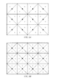
- FIG. 3 is an illustration of a multi-cell layout, wherein all cells have similar frequency reuse patterns.
- FIG. 4 is an illustration of a multi-cell deployment model, wherein the hub grid is shifted by a cell radius between two rows of cells, and where the frequency reuse patterns between cell rows are rotated by ninety-degrees, in accordance with one embodiment of the present invention.
- FIG. 5 is a flow diagram illustrating a method for deploying a multi-cell deployment model, wherein the hub grid is shifted by a cell radius between two rows of cells, and where the frequency reuse patterns between cell rows are differentiated or rotated by ninety-degrees, in accordance with one embodiment of the present invention.
- FIGS. 6A-6C are an illustration of a square cell deployment geometry wireless backhaul network implementing heterogeneous wireless backhaul network expansion techniques in accordance with embodiments of the present invention.
- FIGS. 7A-7C are an illustration of a tier offset cell deployment geometry wireless backhaul network implementing heterogeneous wireless backhaul network expansion techniques in accordance with embodiments of the present invention.
- FIGS. 8A-8C are an illustration of a homogeneous build out of a square cell deployment geometry wireless backhaul network implementing heterogeneous wireless backhaul network expansion techniques in accordance with embodiments of the present invention.
- FIGS. 9A-9C are an illustration of a homogeneous build out of a tier offset cell deployment geometry wireless backhaul network implementing heterogeneous wireless backhaul network expansion techniques in accordance with embodiments of the present invention.
- FIG. 10 is an illustration of a heterogeneous cell deployment geometry wireless backhaul network in accordance with embodiments of the present invention.
- Embodiments of the present invention provide for frequency reuse in a multi-cell deployment model of a wireless backhaul network, wherein the same pair of channels are used in a 1:2 frequency reuse pattern.
- Other embodiments of the present invention provide the above advantage and also provide for improved data rates, uniform distribution of the data throughput (e.g., downlink data rate) peak rate across a single cell, less interference from adjacent sectors in a multi-cell deployment model, less outage at the sector boundaries, and improved carrier to noise plus interference (CINR) ratios.
- data throughput e.g., downlink data rate
- CINR carrier to noise plus interference
- embodiments of the invention provide a backhaul network including a plurality of cells, each of which includes one or more hubs supporting wireless backhaul communication utilizing wireless communication frequency assignments adapted to facilitate expansion of the backhaul network by maintaining an orthogonal frequency face relationship between each cell of a cluster of cells having a number of sectors thereof being expanded and corresponding cell external to the cluster.
- a base station, an access point or a subscriber box form the connection with the end customer.
- the challenge is the connectivity between the base station, access point or subscriber box and the telecommunication infrastructure.
- This connectivity is often referred to as wireless backhaul.
- Wireless backhaul can be provided by a center node, or hub, that controls the wireless communication with one or more remote nodes, or remote stations. These remote nodes and hub connect small base stations, access points or subscriber boxes to their telecommunications provider. Remote nodes are spread out through a community to wirelessly connect small base stations, access points or subscriber boxes to their provider.
- remote nodes are paired with a corresponding base station, access point, or subscriber box, and fixed to a point in space.
- the pair may be deployed on a wall of a building, lamp post, street sign pole, utility pole or any other object that is capable of supporting the pair of devices at street level.
- a wireless backhaul network provides an alternative communication platform over the more typical wired connection back to small base stations, access points or subscriber boxes through buried or suspended telephone lines.
- the network of remote nodes, and corresponding hubs that support the remote nodes is scalable to quickly meet the increase in demand.
- a layout of remote nodes and corresponding hubs is capable of providing wireless backhaul to small base stations, access points or subscriber boxes that is more economical than a service that provides a wired connection to the small base stations, access points or subscriber boxes.
- the network of remote nodes is able to provide telecommunication service to small base stations, access points, or subscriber boxes that cannot be serviced by a fixed-point wired connection.
- FIG. 1 is an illustration of an exemplary communication system 100 that includes a wireless backhaul network, in accordance with one embodiment of the present invention.
- System 100 generally represents a communication network implementing one or more wireless backhaul networks of embodiments of the present invention, and for purposes of clarity and illustration may not include all of the components necessary for a fully functional communication system.
- communication system 100 supports one or more communication protocols suitable for providing communication between one or more end customers 160 and their respective telecommunication infrastructure 120 , and is not intended to be limited to any one particular communication protocol.
- system 100 provides for broadband communication through the delivery of packets between various elements and components providing communication between end customers.
- the same or different communication protocols may be used between different components of communication system 100 .
- the Ethernet protocol may be used between two components of system 100
- the transmission control protocol/internet protocol (TCP/IP) standard may be used between another two components of system 100
- further one of the IEEE 802.16 substandards or fourth generation (4G) long term evolution (LIE) substandards may be also be used between other components of system 100 .
- 4G fourth generation
- LIE long term evolution
- the wireless backhaul network in communication system 100 includes one or more aggregation backhaul modules 110 (hereinafter referred to as “hubs”) that provide access to a telecommunications infrastructure 120 over a wired or wireless interface 105 .
- the telecommunications infrastructure 120 supports telecommunication providers, that in turn support the linking together of various end customers 160 .
- the telecommunications infrastructure 120 supports one or more governmental or commercial providers that support telecommunication services for multiple end customers 160 .
- infrastructure 120 may include a wireless core network for packet and circuit switch voice or data, as well as other communication networks.
- the telecommunications infrastructure 120 links together all customers of the communication system 100 such that a customer from one provider may communicate with another customer from another provider through infrastructure 120 .
- Each of the hubs 110 support a cluster 130 of one or more remote nodes 135 to provide for wireless backhaul.
- the hub 110 controls communication with each of remote nodes 135 within its dedicated cluster 130 of remote nodes, and provides connectivity back to the telecommunication infrastructure 120 .
- hub 110 is a center hub, a sector hub, or a combination of the above.
- Communication with remote nodes 135 requires the communicative coupling of the remote nodes 135 to corresponding hubs 110 through a wireless backhaul network. That is, the backhaul network communicatively couples a remote station 135 with a corresponding hub 110 , which in turn provides for communicative coupling back to the telecommunication infrastructure 120 . More specifically, in one embodiment for increased scalability the backhaul network provides for non-line-of-sight (NLOS) wireless communications between a remote node 135 and a corresponding hub 110 .
- NLOS non-line-of-sight
- a telecommunications provider utilizes a backhaul network to provide communication to its end customers 160 .
- a picocell 139 which is an example of a small base station, access point or subscriber box, provides for wireless communication to one or more end customers 160 , that may or may not be mobile.
- Picocell 139 may support third generation (3G), fourth generation (4G), Wi-Fi and other types and generations of communication networks and/or standards.
- picocell deployment within a geographic area provides for increased coverage in areas that are difficult to service, and provides for increased data throughput in higher traffic areas that need increased bandwidth to support its customers.
- the configuration shown in FIG. 1 utilizing wireless connectivity to end customers through a picocell network may be achieved at a more attractive cost than other services providing connectivity, or last mile coverage, to end customers. For instance, because of its smaller size, typical deployment of one or more picocells may occur on a wall of a building, lamp post, street sign pole, utility pole or any other object that is capable of supporting the device at street level.
- embodiments of the present invention are described within the context of providing a wireless backhaul network providing picocell coverage, other embodiments of the present invention support backhaul networks that communicatively couple end-customers of the remote stations 135 to their telecommunication providers through any type of platform, to include macrocells, femtocells, superfemtocells, outdoor femtocells, access points, compact base stations, etc.
- Embodiments of the invention may, for example, provide wireline links to the end customers, such as by providing Ethernet network links coupled to a remote node herein (e.g., using a router, switch, or other Ethernet network device in place of a picocell shown in FIG. 1 ), to thereby provide wireless backhaul for a wireline network.
- a remote node e.g., using a router, switch, or other Ethernet network device in place of a picocell shown in FIG. 1
- combinations of wireless and wireline end customer equipment may be supported according to embodiments of the invention.
- each picocell 139 is communicatively coupled to a corresponding remote station 135 .
- This may be achieved through a wired or wireless connection.
- a remote station 135 and picocell are deployed together in a single location, such as on a lamppost.
- the devices may be coupled together through a wired connection to provide the best performance over a wired connection.
- a wireless connection may be implemented.
- the end customer 160 is communicatively coupled to its telecommunication provider through a path including a corresponding picocell 139 , remote station 135 , wireless backhaul link to a corresponding hub 110 , and through the telecommunication infrastructure 120 .
- FIG. 2A is an illustration of the deployment of clusters of remote nodes in a cell 250 in a network 200 A providing wireless backhaul throughout cell 250 , in accordance with one embodiment of the present invention.
- the cell 250 in FIG. 2A provides a more detailed illustration of the relationship between hubs and remote nodes provided in FIG. 1 .
- the cell 250 defines a geographic area over which a wireless backhaul network is supported. That is, cell 250 defines the coverage area in which wireless backhaul is available as supported by one or more hubs and remote nodes. More specifically, cell 250 is divided into four sectors, sector 250 A in the upper right corner, sector 250 B in the upper left corner, sector 250 C in the lower left corner, and sector 250 D in the lower right corner.
- cell 250 shows a wireless backhaul coverage area that includes three roads 295 , 297 , and 299 .
- the area defined by cell 250 is representative of any area that requires wireless backhaul services.
- the area may be a downtown region of a small or large town, a suburban area populated by residential homes and small retail businesses, a remote area that is sparsely populated, or a combination of the above.
- cell 250 includes a center hub 210 of a backhaul network 200 A that supports wireless backhaul throughout at least cell 250 .
- a cell, or a sector thereof is not required to have a hub (and correspondingly, need not have remotes deployed therein) if there is insufficient traffic or coverage is otherwise not needed.
- the cell and sector(s) thereof should be planned to ensure optimal performance when, in the future, a hub and remotes are deployed. Such advanced planning of frequency reuse is provided according to embodiments of the present invention.
- center hub 210 is approximately located in the center of cell 250 so that all sectors of cell 250 may be supported equally.
- the center hub 210 supports one or more clusters of remote nodes in order to provide wireless backhaul coverage in the geographic area defined by cell 250 .
- sector 250 A defines a geographic area in cell 250 over which coverage is provided for wireless backhaul by the combination of center hub 210 and a cluster 235 A of remote nodes.
- Cluster 235 A includes remote node 235 A- 1 and remote node 235 A- 2 .
- sector 250 A may be a mountainous area traversed by road 297 , wherein remote nodes in the cluster 235 A are positioned to provide mobile service to users traveling on road 297 .
- sector 250 B defines a geographic area in cell 250 over which coverage is provided for wireless backhaul by center hub 210 and a cluster 235 B of remote nodes.
- Cluster 235 B includes one remote node.
- Sector 250 B may be an area with concentrated usage areas in which the demand for service can be covered using one remote node in cluster 235 B.
- sector 250 C defines a geographic area in cell 250 over which coverage is provided for wireless backhaul by center hub 210 and a cluster 235 C of remote nodes.
- Cluster 235 C includes three remote nodes.
- sector 250 C may be a residential area.
- sector 250 D defines a geographic area in cell 250 over which coverage is provided for wireless backhaul by center hub 210 and a cluster 235 D of remote nodes.
- Cluster 235 D includes four remote nodes.
- sector 250 D may be a more populated area, such as a downtown area, or major commute corridor.
- each cluster providing wireless backhaul to sectors 250 A-D is not fixed.
- cluster 235 A providing. wireless backhaul coverage to sector 250 A includes two remote nodes
- remote nodes may be added or deleted depending on the demand for bandwidth by end customers. That is, if there is an increase in demand, more remote stations may be deployed into sector 250 A, or if already deployed in anticipation may be brought on-line into the wireless backhaul network 200 A.
- the number of customers grows, or as demand for bandwidth grows, throughout a geographic area, more remote nodes can be added to a cluster in a scalable fashion to quickly service the increase in customers and/or demand.
- center hub 210 supports wireless backhaul over the geographic area defined at least by cell 250 . That is, center hub 210 controls and coordinates wireless backhaul with one or more of the clusters of remote nodes 235 A-D in cell 250 . As such, center hub 210 is configured to handle wireless backhaul traffic to one or more sectors throughout cell 250 . In other embodiments, center hub 210 includes one or more sector hubs that are dedicated to control and coordinate wireless backhaul with a corresponding cluster of remote nodes in a particular sector. For instance, as shown in FIG.
- center hub 210 includes sector hubs 210 A- 210 D, where sector hub 210 A provides wireless backhaul to cluster 235 A in sector 250 A, sector hub 210 B provides wireless backhaul to cluster 235 B in sector 250 B, sector hub 210 C provides wireless backhaul to cluster 235 C in sector 250 C, and sector hub 210 D provides wireless backhaul to cluster 235 D in sector 250 D.
- a sector hub provides wireless backhaul to one or more clusters of remote nodes in one or more sectors in cell 250 .
- FIG. 2B is an illustration of part of a network 200 B providing wireless backhaul throughout sector 250 A of cell 250 , in accordance with one embodiment of the present invention.
- sector hub 210 A of center hub 210 provides dedicated wireless backhaul throughout sector 250 A in combination with cluster 235 A of remote nodes.
- the functions provided by sector hub 210 A may be provided solely by center hub 210 .
- Sector hub 210 A includes, in part, radio frequency (RF) equipment 210 A- 1 , as well as other control units for controlling wireless backhaul traffic between the sector hub 210 A and the cluster of remote nodes 235 A.
- Sector hub 210 A also includes one or more antennas 210 A- 2 that spread a corresponding beam pattern 270 throughout sector 250 A.
- the one or more antennas 210 A- 2 are configured such that the beam pattern 270 is focused to primarily provide coverage within sector 250 A. For instance, the main lobe of beam pattern 270 may be concentrated within sector 250 A.
- one or more remote nodes are located within sector 250 A and interact with sector hub 210 A to provide wireless backhaul communication.
- two remote nodes 235 A- 1 and 235 A- 2 are shown in cluster 235 A, although any number of remote nodes may be used.
- the remote nodes in cluster 235 A in combination with sector hub 210 A provide wireless backhaul throughout sector 250 A.
- the remote nodes in cluster 235 A are deployed in a particular pattern to achieve the best signal coverage of the demand exhibited within sector 250 A.
- remote nodes 235 A- 1 and 235 A- 2 may be deployed near road 297 to provide wireless backhaul coverage in support of end customers who may be traveling on road 297 . Additional remote nodes may be included within sector 250 A to provide even better wireless backhaul coverage.
- FIG. 3 is an illustration of a multiple-cell (multi-cell) deployment 300 , wherein all cells have similar frequency reuse patterns.
- a cell consists of multiple sectors that are deployed throughout a geographic area.
- cell 310 is representative of one of the cells, and illustrates a backhaul network that includes a center hub and several remote nodes that are spread across four geographic sectors.
- center hub is approximately located in a center location 315 of cell 310 , depending on constraints due to geographic and physical environment conditions.
- Center hub may include one or more sector hubs, each of which is dedicated to providing wireless backhaul to a corresponding sector of the cell 310 .
- Each sector is capable of supporting one or more remote nodes.
- Cell 310 is generally represented by a square in FIG. 3 . More specifically, the footprint for cell 310 represents a geographic area over which center hub and/or sector hubs and their corresponding remote nodes form a backhaul network.
- cell 310 includes an alternating 1:2 frequency reuse pattern, where two frequency bands or channels (e.g., channels 1 and 2 ) are reused within a single cell, such as cell 310 , to improve the spectral efficiency of the available bandwidth.
- the two channels are alternated between adjacent sectors of cell 310 in an effort to reduce interference problems.
- the frequency reuse pattern is described starting with the sector located in the top-right corner of the cell. As such, starting with sector 313 in the top-right corner of cell 310 , moving in a counter-clockwise direction 319 , the 1:2 frequency reuse pattern is 1-2-1-2.
- cell 310 is used in a repeating pattern throughout the multi-cell deployment 300 .
- a row of cells comprises one or more cells 310 configured such that two adjacent cells 310 in the row share a common edge.
- a common edge 337 is shared by cells defined by hub 334 and hub 339 .
- a column of cells comprises one or more cells 310 configured such that two adjacent cells in the column also share a common edge.
- the hubs in the multi-cell deployment 300 approximately form a uniform grid.
- the deployment 300 is merely representative of the layout of multiple cells 310 over a geographic area.
- the physical layout of hubs of corresponding cells may vary slightly from that depicted in deployment 300 depending on physical and geographic limitations.
- some sectors in deployment 300 may not be populated with corresponding sector hubs and remote nodes. That is, in a particular cell in deployment 300 some sectors may have wireless backhaul coverage while other sector or sectors are without backhaul coverage.
- some cells in deployment 300 may not be populated with corresponding center hubs and remote nodes. In that case, a corresponding cell does not have backhaul coverage. Holes in backhaul coverage within cells or sectors of a cell will often occur while the overall wireless backhaul network is being developed.
- FIG. 3 illustrates a 1:2 frequency reuse pattern in the multi-cell deployment 300
- the interference problem exists in other frequency reuse patterns, such as a 1:1 frequency reuse patter, or 1:3 frequency reuse pattern.
- the interference is further evidenced in the multi-cell deployment model 300 .
- a center cell defined by center location 340 there is interference that is, in part, due to center hub configurations of neighboring cells that lie on a line defining the mid-line of a corresponding sector, or a bore sight of the center cell.
- Neighboring cells include those defined by center location 334 and center location 345 .
- sectors supporting channel “2” lie on a diagonal line Z-Z of the multi-cell deployment 300 running from the top left corner to the lower right corner and through the center hub located at center location 340 , and other hubs located at center locations 334 and 345 .
- any remote station located on the bore sight of the center cell on line Z-Z will see more than one hub from neighboring cells all supporting the same channel. This leads to CINR degradation, especially on the edges and bore sights of the sectors of the center cell defined by center location 340 .
- FIG. 4 is an illustration of a multi-cell deployment 400 , wherein the hub grid is shifted by a cell radius between two cells and/or two rows of cells, and where the frequency reuse patterns between cell rows are rotated by ninety-degrees, in accordance with embodiments of the present invention.
- the multi-cell deployment 400 of FIG. 4 exhibits reduced interference between hubs of neighboring cells, thereby increasing CINR, in one embodiment.
- the multi-cell deployment 400 having a 1:2 frequency reuse pattern outperforms other frequency reuse patterns across the same frequency channels in both single cell and multi-cell scenarios, in other embodiments.
- the multi-cell deployment 400 exhibited in FIG. 4 exhibits a more uniform distribution of data throughput (e.g., downlink) peak rate across a cell, compared to other frequency reuse patterns on the same frequency channels.
- data throughput e.g., downlink
- a first cell 410 and a second cell 420 each of which illustrate a corresponding backhaul network including a center location populated with a center hub, that may include one or more sector hubs, and one or more remote nodes spread throughout sectors of a corresponding cell.
- the frequency pattern of the second cell 420 is similar in configuration to the frequency pattern of the first cell 410 , but is rotated by ninety degrees within deployment 400 , as will be described below.
- First cell 410 illustrates part of a backhaul network that includes a center hub and/or one or more sector hubs approximately located at center location 415 , and one or more remote nodes spread across four geographic sectors. That is, each sector is capable of supporting one or more remote nodes for purposes of forming part of a backhaul network.
- First cell 410 is generally represented by a square in FIG. 4 . More specifically, the footprint for cell 410 represents a geographic area over which a center hub approximately located at a center location 415 communicates with corresponding remote nodes located within the sectors of the cell 410 in order to form a backhaul network.
- center hub at center location 415 includes one or more directional antennas to form corresponding beam patterns into each of the sectors.
- a center and/or sector hub at center location 415 includes a 90 degree horizontal beamwidth antenna having 16 dBi gain that radiates a beam pattern into one of the four sectors of the first cell 410 .
- a remote node located in one of the sectors of the first cell 410 includes a highly directional antenna pointed to a corresponding center and/or sector hub to form a communicative link between the two nodes for providing wireless backhaul.
- the hub to which the antenna is pointed is at the center location 415 of the cell.
- the hub to which the antenna of the remote station is pointed is located in an adjacent cell.
- the remote antenna may form a 15 degree antenna beam with 18 dBi gain.
- the antennas described above are equally applicable to remote node configurations of the second cell 420 .
- first cell 410 is representative of a first 1:2 alternating frequency reuse pattern, where two frequency bands or channels are reused within a single cell to improve the spectral efficiency of the available bandwidth, and is used in the multi-cell deployment 400 .
- the two channels are alternated between adjacent sectors of cell 210 in an effort to reduce interference problems.
- sector 413 is supported by a first channel (represented by the number “I”), and adjacent sectors in cell 410 to sector 413 are supported by a second channel (represented by the number “2”).
- the 1:2 frequency reuse pattern is 1-2-1-2.
- multi-cell deployment 400 includes a second cell 420 that is representative of a second alternating frequency reuse pattern.
- Cell 420 is generally represented by a square footprint including four geographic sectors, each of which may support one or more remote nodes to form a backhaul network with a corresponding hub.
- the second alternating frequency reuse pattern exhibits a 1:2 frequency reuse pattern, where two frequency bands or channels are alternated between adjacent sectors within the second cell 420 .
- the second alternating frequency reuse pattern is similar to the first alternating frequency reuse pattern of the first cell 410 , but is rotated by ninety degrees, such that the first channel is now in the top left sector 421 and lower right sector 425 .
- the second alternating frequency reuse pattern provides a 2-1-2-1 pattern, again where a first channel “1” and a second channel “2” alternate between adjacent sectors.
- the frequency bandwidth allocated to the first cell 410 and the second cell 420 is a combined total of approximately 20 MHz.
- the total bandwidth is allocated equally between the two channels.
- the first channel includes a bandwidth of 10 MHz
- the second channel includes a bandwidth of 10 MHz.
- the first channel and the second channel do not have contiguous frequencies.
- the combined frequency bandwidth allocated to the first cell 410 and the second cell 420 combined is less than 20 MHz.
- the first channel could include a bandwidth of 3, 5, 7 or 10 MHz (as examples), and the second channel includes a bandwidth of 3, 5, 7 or 10 MHz (as examples).
- the total bandwidth may or may not be allocated equally between the two channels.
- the first channel and the second channel do not have contiguous frequencies.
- the combined frequency bandwidth allocated to both the first cell 410 and the second cell 420 is more than 20 MHz.
- the first channel includes a bandwidth of 3, 5, 7, 10, 15 or 20 MHz (as examples)
- the second channel includes a bandwidth of 3, 5, 7, 10, 15 or 20 MHz (as examples).
- the total bandwidth may or may not be allocated equally between the two channels.
- the first channel and the second channel do not have contiguous frequencies.
- the configuration of hubs in the backhaul network includes a first cell and a second cell, as previously described, in accordance with one embodiment of the present invention.
- one first cell 410 includes a center hub, that may include one or more sector hubs, and is centrally located approximately at center location 430 .
- This first cell may also be referred to as the center cell, and is outlined by a bolded and solid line.
- the backhaul network layout includes one second cell 420 including a center hub, that may include one or more sector hubs, wherein the second cell 420 is centrally located approximately at center location 440 , and is outlined by a bolded and dotted line.
- the second cell located at center location 440 is vertically adjacent to the center cell defined by center location 430 . That is, as shown in FIG. 4 , the second cell located approximately at center location 440 is located geographically above the center cell located approximately at center location 430 .
- the second cell is offset the first cell by a cell radius. More particularly, a vertical line D-D through the center hub located at center location 440 of the second cell is offset from a parallel vertical line A-A through the center hub located at center location 430 of the first cell by a cell radius 485 (i.e., cell 440 is offset horizontally with respect to call 430 ), in one embodiment. As shown in FIG. 4 , the cell radius 485 is one-half of the full edge 480 of a representative cell. Put another way, cell radius 485 is half the distance between the center locations of two adjacent cells in a row of cells, such as the row defined by line B-B, in another embodiment.
- the center hub located at center location 440 of the second cell is offset from the vertical line A-A by cell radius 485 , and is located on vertical line D-D.
- the second cell 420 as defined by center location 440 shares one-half of a full edge with the first cell 410 defined by center location 430 , in another embodiment.
- the second cell 420 that is vertically adjacent to the first cell 410 or center cell defined by center location 440 could be located in anyone of four locations. Specifically, the second cell 420 could be vertically located above the center cell and offset to the right by a cell radius 485 to include center location 440 , as described above. In addition, the second cell 420 could be vertically located above the center cell defined by center location 430 and offset to the left by a cell radius 485 to include center location 443 . Also, the second cell 420 in the backhaul network could be vertically located below the center cell defined by center location 430 and offset to the right by a cell radius 485 to include center location 445 . Further, the second cell 420 in the backhaul network could be vertically located below the center cell defined by center location 430 , and offset to the left by a cell radius 485 to include center location 447 .
- the multi-cell deployment 400 illustrates another backhaul network.
- the backhaul network includes a plurality of cells, and more specifically, includes first cells 410 and second cells 420 .
- each of the first or second cells comprises a center hub, that may include one or more sector hubs, supporting wireless backhaul communication over four corresponding geographic sectors.
- the backhaul network includes a first row 460 of the plurality of cells.
- the first row 460 comprises a plurality of first cells 410 previously described. That is, each of the first cells 410 is configured to support a first alternating frequency reuse pattern of a first channel and a second channel over four corresponding geographic sectors.
- adjacent first cells 410 in the first row 460 are aligned without any offset. That is, edges of two adjacent cells are aligned without any offset, such that the two adjacent first cells 410 share an edge.
- center hubs in the first cells 410 of the first row 460 lie approximately on a horizontal line (e.g., line B-B). For instance, as shown in FIG. 4 , the center cell defined by center location 430 is adjacent to another first cell 410 located directly to the right, and to another first cell 410 located directly to the left. Row 460 includes other first cells 410 (not shown) following the same configuration described above, in one embodiment.
- the backhaul network includes a second row 450 of the plurality of cells.
- the second row comprises a plurality of second cells 420 previously described. That is, each of the second cells is configured to support a second alternating frequency reuse pattern over four corresponding geographic sectors.
- the second alternating frequency reuse pattern comprises the first alternating frequency reuse pattern that is rotated by ninety degrees.
- adjacent second cells 420 in the second row 450 are aligned without any offset. That is, edges of the two adjacent cells are aligned without any offset, such that the two adjacent second cells 420 share an edge.
- center hubs in the second cells of the second row 450 lie approximately on a horizontal line, that is approximately parallel to line B-B. For instance, as shown in FIG. 4 , the cell defined by center location 443 is adjacent to another second cell 420 located to the right that is defined by center location 440 .
- Row 450 includes additional second cells 420 (not shown) following the same configuration described above, in one embodiment.
- the second row 450 is adjacent to the first row 460 . As shown in FIG. 4 , second row 450 is located above first row 460 , but could be located below first row 460 , as evidenced by row 470 that also includes a plurality of second cells 420 . In addition, the second row 450 is offset by a cell radius 485 from the first row 460 , such that a corresponding second cell in the second row 450 is adjacent to a corresponding first cell 410 in the first row 460 , and is offset by a cell radius 485 , or offset by half a full edge 480 of the corresponding first cell 410 or second cell 420 .
- the second cell 420 in the second row 450 is vertically adjacent to a corresponding first cell 410 in the first row 460 (such as the second cell defined by center location 440 and the first cell defined by center location 430 ).
- a vertical line D-D through the center location 440 of the second cell 420 in the second row 450 is offset from a vertical line A-A through the center location 430 of the corresponding first cell 410 in the first row 460 by a cell radius 485 .
- This relationship is repeated for corresponding first cells 310 and corresponding second cells 320 in both first and second rows 460 and 450 , respectively.
- the backhaul network includes a third row of cells, in one embodiment.
- the third row comprises another plurality of second cells 420 , each of which is configured to support the second alternating reuse pattern over four corresponding geographic sectors.
- adjacent second cells 420 in the third row 470 are aligned without any offset. That is, edges of the two adjacent cells are aligned without any offset, such that the two adjacent second cells 420 share an edge.
- center hubs in the cells of the third row 470 lie approximately on a horizontal line, that is approximately parallel to lines B-B and C-C. For instance, as shown in FIG. 4 , the second cell defined by center location 447 is adjacent to another second cell 420 located to the right that is defined by center location 445 .
- Row 470 includes additional second cells 420 (not shown) following the same configuration described above, in one embodiment.
- the third row 470 is adjacent to the first row 460 , such that the first row 460 is between the second row 450 and the third row 470 .
- a corresponding second cell 420 in the third row 470 is aligned to a corresponding first cell 410 in the first row 460 with an offset of a cell radius 485 , or half an edge of the first cell 410 .
- third row 470 is located below first row 460 .
- the third row 470 is offset by a cell radius 485 from the first row 460 , such that a corresponding second cell in the third row 470 is adjacent to a corresponding first cell 310 in the first row 460 , and is offset by a cell radius 485 , or offset by half a full edge 480 of the first cell 410 or second cell 420 .
- the second cell 420 in the third row 470 is vertically adjacent to a corresponding first cell 410 in the first row 460 (such as the second cell 420 defined by center location 447 and the first cell 410 defined by center location 430 ).
- the center hub(s) of second cells 420 in the third row 470 is offset from the center hub(s) of corresponding first cells 410 in the first row 460 by a cell radius 485 .
- a vertical line D-D through the center location 445 of the second cell 420 in the third row 470 is offset from a vertical line A-A through the center location 430 of the corresponding first cell 410 in the first row 460 by a cell radius 485 . This relationship is repeated for corresponding first cells 410 and corresponding second cells 420 in both first and third rows.
- the backhaul network includes a fourth row of cells (not shown), in one embodiment.
- the fourth row comprises another plurality of first cells 410 , each of which is configured to support the first alternating reuse pattern over four corresponding geographic sectors.
- adjacent first cells 410 in the fourth row are aligned without any offset. That is, edges of the two adjacent cells are aligned without any offset, such that the two adjacent first cells 410 share an edge.
- hubs in the cells of the fourth row lie approximately on a horizontal line that is approximately parallel to line B-B and to line C-C.
- the fourth row is adjacent to the second row 450 , such that the second row 450 is between the first row 460 and the fourth row (not shown), and wherein a corresponding first cell in the fourth row is aligned to a corresponding second cell in the second row 450 with an offset of a cell radius 485 , or half a full edge 480 , as previously described.
- the fourth row could be adjacent to the third row 470 , such that the third row 470 is between the first row 460 and the fourth row (not shown), and wherein a corresponding first cell in the fourth row is aligned to a corresponding second cell in the third row 470 with an offset of a cell radius 485 , or half a full edge 480 , as previously described.
- the multi-cell deployment 300 illustrates another backhaul network.
- the backhaul network includes a plurality of cells, and more specifically, includes first cells 410 and second cells 420 .
- each of the first or second cells comprises one or more hubs supporting wireless backhaul communication over four corresponding geographic sectors.
- the backhaul network is comprised of two or more tiers of cells.
- a first tier of cells comprises a center cell that is configured to support a first alternating frequency reuse pattern of a first channel and a second channel over four corresponding geographic sectors.
- the center cell comprises a first cell 410 , and includes center location 430 .
- a second tier of cells surrounds the first tier.
- the second tier includes a first cell 410 configured to support the first alternating reuse pattern, and wherein the first cell 410 is located horizontally adjacent to the center cell defined by center location 430 .
- the second tier includes both the first cells 410 located to the right and left of the center cell defined by center location 430 , such as the first cell 410 defined by center location 435 and first cell 410 defined by center location 437 .
- the second tier of cells includes at least one second cell 420 that is configured to support the second alternating frequency reuse pattern.
- the second cell 420 is located vertically adjacent to the center cell defined by center location 430 .
- the second cell 420 is located above and below the center cell.
- the second cell 420 is offset from the center cell by a cell radius 485 , as previously described, and for example, such that the second cell 420 and the center cell share one half of a full edge 480 of a representative cell.
- the second tier could include second cells defined by hubs 440 , 443 , 445 , and 447 .
- the second tier includes each of the cells defined by hubs 435 , 437 , 440 , 443 , 445 , and 447 .
- the second tier of cells includes 6 cells comprising both first cells 410 and second cells 420 , in one embodiment.
- the backhaul network includes a third tier of cells of 12 cells (not shown) surrounding the second tier of cells, and comprises both first cells 410 and second cells 420 that maintain the cell configuration and layout described above.
- the deployment 400 is merely representative of the layout of multiple cells over a geographic area.
- the physical layout of center hubs of corresponding cells may vary slightly from that depicted in deployment 400 depending on physical and geographic limitations.
- some sectors in deployment 400 may not be populated with corresponding sector hubs and remote nodes. That is, in a particular cell in deployment 400 some sectors may have wireless backhaul coverage while other sector or sectors are without backhaul coverage.
- some cells in deployment 400 may not be populated with corresponding center hubs and remote nodes. In that case, a corresponding cell does not have backhaul coverage. Holes in backhaul coverage within cells or sectors of a cell will often occur while the overall wireless backhaul network is being developed.
- CINR degradation is greatly reduced along sector bore sights, and along vertical edges of sectors for a corresponding cell. This is mainly due to the offset of hubs of neighboring cells, since interference stems mostly from the sidelobe of a corresponding beam pattern radiating into one of those sectors, and not from the main beam.
- hubs between first and second tiers do not lie on any of the diagonals of the center cell defining the first tier, wherein the diagonals are formed between the corners of the center cell and the center location that is occupied by the hub.
- hubs for neighboring cells in the second tier do not lie on any of these diagonals, thereby reducing interference between beam patterns of center hubs in the first and second tier.
- FIG. 5 is a flow diagram 500 illustrating a method for deploying a multi-cell deployment model, wherein the hub grid is shifted by a cell radius between two rows of cells, and where the frequency reuse patterns between cell rows are rotated by ninety-degrees, in accordance with one embodiment of the present invention.
- the method outlined in FIG. 5 is implementable for deploying various embodiments of the multi-cell deployment 400 illustrated in FIG. 4 , in accordance with embodiments of the present invention.
- the method includes defining 510 a first cell (e.g., cell 410 ) that includes a center hub, that may include one or more sector hubs, and one or more remote nodes spread across four geographic sectors. Also, the first cell is configured to support a first alternating frequency reuse pattern, previously described, that utilizes a first channel and a second channel over the four corresponding geographic sectors.
- the footprint for the first cell represents a geographic area over which the center hub extends corresponding beam patterns for communication with corresponding remote nodes located within corresponding sectors deployed in a first cell in order to form a backhaul network.
- the method also includes defining 520 a second cell (e.g., cell 420 ) that includes a center hub, that may include one or more sector hubs, and one or more remote nodes spread across four geographic sectors.
- the second cell is configured to support a second alternating frequency reuse pattern, previously described.
- the second alternating frequency reuse pattern comprises the first alternating frequency reuse pattern that is rotated by ninety degrees.
- the footprint for the second cell represents a geographic area over which the center hub extends corresponding beam patterns for communication with corresponding remote nodes located in corresponding sectors deployed in a second cell in order to form a backhaul network.
- the first cell is deployed 530 over a geographic area. That is, the center hub of the first cell is deployed with one or more directional antennas that form corresponding beam patterns into each of the four sectors defining the geographic area. As such, the center hub is able to communicate with one more remote nodes spread throughout four sectors of the first cell to form a backhaul network.
- the second cell is deployed 540 over a geographic area. That is, a corresponding center hub of the second cell is deployed with one or more directional antennas that form corresponding beam patterns into each of the four sectors defining the geographic area. As such, the center hub of the second cell is able to communicate with one or more remote nodes spread throughout four sectors to form a backhaul network.
- the second cell is vertically adjacent to the first cell. That is, the second cell is located geographically above or below the center cell in a vertical direction.
- the second cell is offset from the first cell by a cell radius, or one-half a full edge of representative cell, as previously described. That is, the second cell could be offset to the left or right, and above or below the first cell. As such, the first cell and the second cell share one half of a full edge of a respective one of the cells.
- the backhaul network formed by the method outlined in FIG. 5 is extendable to create rows of cells.
- a first row is deployed, wherein the first row comprises a plurality of first cells, and includes the first cell that is deployed.
- Adjacent first cells in the first row are aligned without any offset. That is, edges of the two adjacent cells are aligned without any offset, such that the two adjacent first cells share an edge.
- center hubs in the cells of the first row lie approximately on a horizontal line.
- the backhaul network is extendable to create another row of cells.
- a second row is deployed, wherein the second row comprises a plurality of second cells, and includes the second cell that is deployed.
- Adjacent second cells in the second row are aligned without any offset. That is, edges of the two adjacent cells are aligned without any offset, such that the two adjacent second cells share an edge.
- center hubs in the cells of the second row lie approximately on a horizontal line, that is approximately parallel to the horizontal line defined as intersecting center hubs for first cells in the first row above.
- the second row is deployed adjacent to the first row. Also, the second row is offset by a cell radius from the first row, such that a corresponding second cell in the second row is adjacent to a corresponding first cell in the first row, and is offset by a cell radius, such that the second cell and the first cell share one half of a full edge of a representative cell.
- a third row is deployed that comprises another plurality of second cells. Edges of two adjacent second cells in the third row are aligned without any offset.
- the third row is adjacent to the first row, and opposite the second row such that the first row is between the second and third rows. Also, the third row is offset by a cell radius from the first row, such that a corresponding second cell in the third row is adjacent to a corresponding first cell in the first row, and is offset by a cell radius, as previously described. For instance, a second cell in the third row and a first cell in the first row share one half of a full edge of a representative cell.
- a fourth row is deployed that comprises another plurality of first cells. Edges of two adjacent first cells in the fourth row are aligned without any offset.
- the fourth row is adjacent to the third row, and opposite the first row, such that the third row is between the fourth and the first rows.
- the fourth row is offset by a cell radius from the third row, such that a corresponding first cell in the fourth row is adjacent to a corresponding second cell in the third row, and is offset by a cell radius, as previously described. For instance, a corresponding first cell in the fourth row and a corresponding second cell in the third row share one half of a full edge of a representative cell.
- Frequency reuse patterns such as one or more of the foregoing exemplary frequency reuse patterns, may be utilized in accordance with embodiments of the invention to facilitate frequency planning for initial deployment, build out, and expansion (e.g., increased sectorization and channel reuse to provide increased communication capacity and/or more frequency robustness) in wireless backhaul networks which include a plurality of cells as described herein.
- embodiments comprise a plurality of cells providing wireless backhaul communication implementing a predetermined wireless frequency reuse pattern providing alternating utilization of a plurality of wireless communication frequencies by the cells of the backhaul network.
- the cell deployment geometry and frequency assignments are preferably made to accommodate the aforementioned expansion within the wireless backhaul network, such as to facilitate expansion of cell configurations from omni-directional to bi-sectored, from bi-sectored to quad-sectored, from quad-sectored to octal-sectored, etc. as demand, usage patterns, and/or other conditions change.
- a plurality of hubs are disposed in a predetermined cell deployment geometry to provide communication services within a composite service area.
- Cells such as those of the exemplary embodiments of FIGS. 6A and 7A , may comprise one or more sectors that are deployed throughout a geographic area.
- a hub is approximately located in a center location of a cell, depending on constraints due to geographic and physical environment conditions.
- Such a hub may include one or more sector hubs, each of which is dedicated to providing wireless backhaul to a corresponding sector of the cell. Each such sector is capable of supporting one or more remote nodes.
- the footprint for a cell such as shown in FIGS.
- FIG. 6A represents a geographic area over which the hub, or the sector hubs thereof, provides wireless communications for remote nodes served by the wireless backhaul network.
- FIG. 6A shows wireless backhaul network 600 including hubs 601 - 616 disposed in a square cell deployment (i.e., cell centers aligned in rows and columns) geometry to define respective cells 621 - 636 , wherein cells 621 - 636 cooperate to provide communication services within the composite service area of wireless backhaul network 600 .
- FIG. 6A shows wireless backhaul network 600 including hubs 601 - 616 disposed in a square cell deployment (i.e., cell centers aligned in rows and columns) geometry to define respective cells 621 - 636 , wherein cells 621 - 636 cooperate to provide communication services within the composite service area of wireless backhaul network 600 .
- FIG. 6A shows wireless backhaul network 600 including hubs 601 - 616 disposed in a square cell deployment (i.e., cell centers aligned in rows
- wireless backhaul network 700 including hubs 701 - 716 disposed in a tier offset cell deployment geometry (cells of different rows of cells are adjacent but center offset by half an edge) to define respective cells 721 - 736 , wherein cells 721 - 736 cooperate to provide communication services within the composite service area of wireless backhaul network 700 .
- the cells of the wireless backhaul networks implement alternating frequency assignments, as described herein.
- two frequency bands or channels e.g., channels 1 and 2
- the two channels are alternated between adjacent cells in an effort to reduce interference problems.
- cells of the present invention which are expanded to multi-sectored cells themselves implement an alternating frequency reuse pattern, where the two frequency bands or channels (e.g., channels 1 and 2 ) are reused within a single cell, such as to improve the spectral efficiency of the available bandwidth.
- the alternating frequency assignments provide orthogonal frequency faces (i.e., adjacent cell edges, wherein the cells having the adjacent cell edges utilize different frequencies within those sectors) which mitigate mutual interference with respect to the adjacent cells.
- the adjacent cell edges of cells 621 and 622 provide orthogonal frequency face 651 due to the omni-sector of cell 621 (providing one of the adjacent cell edges) having frequency 2 assigned thereto and the omni-sector of cell 622 (providing the other of the adjacent cell edges) having frequency 1 assigned thereto.
- the adjacent cell edges of cells 621 and 625 provide orthogonal frequency face 652 due to the omni-sector of cell 621 (providing one of the adjacent cell edges) having frequency 2 assigned thereto and the omni-sector of cell 625 (providing the other of the adjacent cell edges) having frequency 1 assigned thereto. Accordingly, although the opposing omni-sectors of these cells present broadside views with respect to each other (i.e., the azimuthal direction of the sectors, here omni-directional, are aimed directly at each other), their assignment of orthogonal wireless communication frequencies mitigates their mutual interference.
- the tier offset cell deployment geometry of wireless backhaul network 700 shown in FIG. 7A provides orthogonal frequency faces which mitigate mutual interference with respect to adjacent cells.
- the adjacent cell edges of cells 721 and 722 provide orthogonal frequency face 751 due to the omni-sector of cell 721 (providing one of the adjacent cell edges) having frequency 2 assigned thereto and the omni-sector of cell 722 (providing the other of the adjacent cell edges) having frequency 1 assigned thereto.
- the adjacent cell edges of cells 721 and 725 provide orthogonal frequency face 752 due to the omni-sector of cell 721 (providing one of the adjacent cell edges) having frequency 2 assigned thereto and the omni-sector of cell 725 (providing the other of the adjacent cell edges) having frequency 1 assigned thereto.
- the adjacent cell edges of cells 721 and 726 provide non-orthogonal frequency face 753 due to the omni-sector of cell 721 (providing one of the adjacent cell edges) having frequency 2 assigned thereto and the omni-sector of cell 726 (providing the other of the adjacent cell edges) also having frequency 2 assigned thereto.
- the tier offset configuration of these cells disposes their hubs apart from each other a distance greater than their cell radius, thereby mitigating at least to some extent their mutual interference.
- the tier offset cell deployment geometry provides satisfactory wireless communication operation in various instances and provides a cell geometry option that may be desirable in particular situations (e.g., where cell site locations for square cell or other deployment configurations are not available).
- a tier offset cell deployment geometry may facilitate particular wireless backhaul expansion growth paths (e.g., sector division and frequency assignments) which are desired over other cell geometries, such as the aforementioned square cell deployment geometry.
- the omni-sector configurations of FIGS. 6A and 7A provide wireless communication coverage of the composite service areas of the respective wireless backhaul networks.
- adequate wireless communication service may not be provided to the remote nodes disposed within the cells of the wireless backhaul networks.
- a multiple access technique e.g., time division multiple access (TDMA), code division multiple access (CDMA), orthogonal frequency division multiple access (OFDMA), etc.
- TDMA time division multiple access
- CDMA code division multiple access
- OFDMA orthogonal frequency division multiple access
- a need for expansion in the wireless backhaul network may be presented during the operational life of the network.
- cells having any number of sectors may initially provide satisfactory service, a need for expansion in the wireless backhaul network may be presented during the operational life of that particular configuration.
- frequency reuse patterns of embodiments herein are adapted to facilitate heterogeneous expansion in wireless backhaul networks (i.e., expansion in only a portion of the wireless backhaul network).
- the frequency reuse pattern of embodiments is adapted to accommodate heterogeneous expansion in the wireless backhaul network by dividing each cell of a selected cluster of cells to provide added sectors.
- Frequency assignments are made according to embodiments such that adjacent cells provide orthogonal frequency faces with respect to one another. Such orthogonal frequency faces comprise a cell edge of a cell associated with a frequency of the plurality of wireless communication frequencies which is adjacent to a cell edge of another cell associated with a different frequency of the plurality of wireless communication frequencies to thereby mitigate mutual interference.
- the frequency assignments are further made according to embodiments such that, where orthogonal frequency faces are not maintained between adjacent cell edges as sectors are added, non-broadside common frequency views are provided with respect to the particular opposing sectors for which orthogonal frequency faces are not provided. Such non-broadside common frequency views comprise the azimuthal direction of the opposing sectors being offset, such as by 20° or more, to thereby mitigate mutual interference.
- the foregoing frequency reuse patterns are adapted to accommodate heterogeneous expansion in the wireless backhaul network by dividing each cell of a selected cluster of cells to provide added sectors while mitigating interference by maintaining the orthogonal frequency face relationships and/or providing non-broadside common frequency views between opposing sectors of the wireless backhaul network.
- FIGS. 6B and 7B illustrate heterogeneous expansion in the wireless backhaul networks of FIGS. 6A and 7A , respectively, using frequency reuse patterns in accordance with the concepts of the present invention.
- a cluster of cells within the respective wireless backhaul network is selected for expansion by dividing each cell of a selected cluster of cells to provide added sectors.
- cells 626 , 627 , 630 , and 631 were selected as a cluster of cells (shown as cluster 600 B) for expansion in FIG. 6B .
- cells 726 , 727 , 730 , and 731 were selected as a cluster of cells (shown as cluster 700 B) for expansion.
- the cluster cells are expanded (as compared to their previous configuration shown in FIGS. 6A and 7A ) by dividing each cell of a selected cluster of cells to provide added sectors (shown here as omni-sectored to bi-sectored expansion).
- the cells external to the selected cluster of cells selected for expansion i.e., cells 621 - 624 , 625 , 628 , 629 , and 632 - 636 in FIG. 6B and cells 721 - 724 , 725 , 728 , 729 , and 732 - 736 in FIG. 7B
- the expansion of the cluster cells within these exemplary wireless backhaul networks is heterogeneous.
- Selection of the particular cells within a wireless backhaul network for expansion using heterogeneous wireless backhaul network expansion techniques of the present invention is preferably based upon a plurality of criteria.
- at least one cell of the cluster of cells is selected based upon a wireless backhaul network operational goal and at least one cell of the cluster of cells is selected based upon a heterogeneous expansion goal.
- a wireless backhaul network operational goal may be to provide additional wireless communication capacity (e.g., to serve an increase in demand) within one or more selected cell of the wireless backhaul network through expanding the number of sectors and frequency assignments in the selected cell or cells.
- a heterogeneous expansion goal may be to expand the number of sectors and frequency assignments of one or more cells adjacent to a cell or cells selected for service goal expansion in order to provide orthogonal frequency faces and/or non-broadside common frequency views with respect to the cluster cells and external cells after expansion.
- the configuration of cells comprising clusters 600 B and 700 B are selected according to embodiments based upon both network operational goals and heterogeneous expansion goals.
- FIGS. 6B and 7B show clusters 600 B and 700 B comprising 4 cells
- the concepts of the invention are not limited to clusters of 4 cells.
- cell 726 may be selected for service goal expansion and cell 727 may be selected for expansion goal expansion (as will be better understood from the discussion which follows) to thereby define a cluster of cells for heterogeneous expansion wherein suitable interference mitigation is provided by maintaining the orthogonal frequency face relationships and/or providing non-broadside common frequency views between opposing sectors of the wireless backhaul network.
- suitable interference mitigation is provided by maintaining the orthogonal frequency face relationships and/or providing non-broadside common frequency views between opposing sectors of the wireless backhaul network.
- cell 7B may, for example, be a result of cells 726 and 730 being selected for service goal expansion and cells 727 and 731 correspondingly being for expansion goal expansion.
- cell 626 may be selected for service goal expansion and cells 627 , 630 , and 631 may be selected for expansion goal expansion to thereby define a cluster of cells for heterogeneous expansion wherein suitable interference mitigation is provided by maintaining the orthogonal frequency face relationships and/or providing non-broadside common frequency views between opposing sectors of the wireless backhaul network.
- cluster configurations i.e., the number cluster cells, the relative positions of the cluster cells, etc.
- various cluster configurations may be utilized according to embodiments of the invention, such as based upon cell deployment geometry, sector dividing techniques used, service goals, etc.
- the cluster cells of FIGS. 6B and 7B having been expanded to multi-sectored cells, are assigned wireless communication frequencies implementing an alternating frequency reuse pattern, where the two frequency bands or channels (e.g., channels 1 and 2 ) are reused within each such cell.
- cell 626 is divided diagonally to provide a bi-sectored cell configuration for the aforementioned service goal expansion.
- cells 627 , 630 , and 631 are divided diagonally to provide bi-sectored cell configurations for the aforementioned expansion goal expansion.
- the frequency assignments for the sectors of the expanded cells are made to maintain the orthogonal frequency faces around the periphery of cluster 600 B. That is, the frequency assignments made in the embodiment illustrated in FIG.
- the frequency reuse plan implemented with respect to the heterogeneous expansion in wireless backhaul network 600 of FIG. 6B mitigates interference by maintaining the orthogonal frequency face relationships between the cluster cells and the adjacent external cells.
- cells 726 and 730 are divided perpendicular (divided vertically in the illustrated embodiment) to the to the row offset (horizontal offset in the illustrated embodiment) to provide a bi-sectored cell configuration for the aforementioned service goal expansion.
- cells 727 and 731 are divided perpendicular to the row offset to provide the aforementioned expansion goal expansion.
- the frequency assignments for the sectors of the expanded cells are made to maintain the orthogonal frequency face relationships and/or provide non-broadside common frequency views between opposing sectors in wireless backhaul network 700 .
- the frequency assignments made with respect to the left most sectors of cells 726 and 730 and the right most sectors of cells 727 and 731 maintain the orthogonal frequency faces with adjacent external cells 725 , 728 , 729 , and 732 .
- the frequency assignments made with respect to the right most sectors of cells 726 and 730 and the left most sectors of cells 727 and 731 provide both orthogonal frequency faces with respect to adjacent cluster cells and non-broadside common frequency views (i.e., the azimuthal direction of opposing sectors having the same frequency assignment are offset, as represented by sector beam directional vectors 751 and 752 not pointing directly at the hub of adjacent cells 722 and 735 using a common frequency) with respect to adjacent external cells 722 and 735 .
- the frequency reuse plan implemented with respect to the heterogeneous expansion in wireless backhaul network 700 of FIG. 7B mitigates interference by maintaining the orthogonal frequency face relationships and by providing non-broadside common frequency views between opposing sectors in the wireless backhaul network.
- the dividing of the cluster cells may be performed in various configurations for maintaining the orthogonal frequency face relationships and/or providing non-broadside common frequency views between opposing sectors in the wireless backhaul network.
- a particular sector division configuration used to provide heterogeneous wireless backhaul network expansion may be selected depending upon cell deployment geometry, the number of existing sectors and the number of added sectors, the configurations of adjacent cell sectors, etc.
- Different sector division configurations e.g., vertical, horizontal, diagonal, slant, etc.
- FIG. 7C shows heterogeneous expansion from bi-sector cells to quad-sector cells
- FIG. 6C shows heterogeneous expansion from quad-sector cells to octo-sector cells, all using heterogeneous wireless backhaul network expansion techniques as described above.
- the frequency assignments for the sectors of the expanded cells in the bi-sector to quad-sector heterogeneous expansion of FIG. 7C are made to maintain the orthogonal frequency face relationships and/or provide non-broadside common frequency views between opposing sectors in wireless backhaul network 700 .
- the frequency assignments made with respect to the upper left most sector of cell 726 and the lower left most sector of cell 726 maintain the orthogonal frequency faces with adjacent external cells 721 and 725 , respectively.
- the frequency assignments made with respect to the upper left most sector of cell 772 and the lower left most sector of cell 726 provide non-broadside common frequency views (i.e., the azimuthal direction of opposing sectors having the same frequency assignment are offset, as represented by sector beam directional vectors 761 and 762 as well as 763 and 764 not pointing directly at one another) with respect to adjacent external cells 725 and 729 , respectively.
- the frequency reuse plan implemented with respect to the heterogeneous expansion in wireless backhaul network 700 of FIG. 7C mitigates interference by maintaining the orthogonal frequency face relationships and by providing non-broadside common frequency views between opposing sectors in the wireless backhaul network according to the concepts herein.
- the frequency assignments for the sectors of the expanded cells in the quad-sector to octo-sector heterogeneous expansion of FIG. 6C are made to maintain the orthogonal frequency face relationships and/or provide non-broadside common frequency views between opposing sectors in wireless backhaul network 600 .
- the frequency assignments made with respect to the lower left most sector of cell 626 in which frequency 2 is assigned maintains the orthogonal frequency face with adjacent external cell 625 .
- the frequency assignments made with respect to the upper left most sector of cell 626 in which frequency 1 is assigned provides non-broadside common frequency views (i.e., the azimuthal direction of opposing sectors having the same frequency assignment are offset, as represented by sector beam directional vectors 661 and 662 not pointing directly at one another) with respect to adjacent external cell 625 .
- the frequency reuse plan implemented with respect to the heterogeneous expansion in wireless backhaul network 600 of FIG. 6C mitigates interference by maintaining the orthogonal frequency face relationships and by providing non-broadside common frequency views between opposing sectors in the wireless backhaul network according to the concepts herein.
- the frequency assignments made in implementing heterogeneous wireless backhaul network expansion techniques may utilize various frequency reuse patterns to implement alternating frequency assignments as described herein.
- alternating frequency reuse patterns such as the aforementioned technique wherein a second tier includes a second cell configured to support a second alternating reuse pattern wherein the second alternating frequency reuse pattern includes a first alternating frequency reuse pattern rotated by ninety degrees, may be utilized when implementing heterogeneous wireless backhaul network expansion techniques according to embodiments of the invention.
- FIGS. 8A-9C Examples of homogeneous networks as may be built out using the foregoing heterogeneous wireless backhaul network expansion techniques are shown in FIGS. 8A-9C .
- FIG. 8A square cell deployment geometry
- 9 A tier offset cell deployment geometry
- FIGS. 8B and 9B show wireless backhaul networks homogeneously built out to include quad-sector cells
- FIGS. 8A-9C show wireless backhaul networks homogeneously built out to include quad-sector cells
- 8C and 9C show wireless backhaul networks homogeneously built out to include octo-sector cells. It should be appreciated that the frequency assignments implemented in the wireless backhaul network of FIG. 9C utilizes various frequency reuse patterns to implement the alternating frequency assignments.
- the aforementioned technique wherein the second tier includes a second cell configured to support a second alternating reuse pattern wherein the second alternating frequency reuse pattern includes the first alternating frequency reuse pattern rotated by ninety degrees is implemented.
- wireless backhaul networks implementing concepts of the present invention are not limited to the network configurations illustrated in the exemplary embodiments.
- wireless backhaul networks in accordance with embodiments herein may comprise any number of cells deployed within any size and shape of geographic region, and thus are not limited to the relatively small, square configurations illustrated herein.
- hubs (or sector hubs) of one or more cells of any cell deployment geometry need not be deployed where no remote node is present, thereby leaving one or more wireless communication gaps within the service area of the wireless backhaul network.
- cell deployment geometries other than those of the foregoing exemplary embodiments may implement heterogeneous wireless backhaul network expansion techniques of the present invention.
- a tier offset cell deployment geometry may implement an offset with respect to cells of different columns rather than the row offset configuration illustrated in FIG. 7A .
- cell deployment geometries may be combined, such as to dispose some cells of a first cell deployment geometry within a wireless backhaul network having cells of a second cell deployment geometry, to thereby provide a heterogeneous cell deployment geometry.
- FIG. 10 shows a tier offset cell deployment geometry of cells (cells 1027 - 1033 ) disposed within cells of a square cell deployment geometry of cells (cells 1021 - 1026 and 1031 - 1036 ), wherein cells 1027 and 1030 provide a reduced cell footprint to accommodate the tier offset cell deployment geometry being disposed within the square cell deployment geometry.
- frequency 1 as utilized by various sectors of a wireless backhaul network may comprise wireless communication channels of different bandwidths (e.g., 5 MHz, 7 MHz, 10 MHz, etc.) as appropriate to the demand within the particular sector.
- wireless communication channels designated as a particular frequency reference e.g., frequency 1 and frequency 2
- communication channels of different sectors designated as frequency 1 may each comprise a different frequency band, as long as those frequency bands are non-overlapping with respect to the frequency bands utilized by sectors designated as frequency 2 .
- the sectors of embodiments herein are not limited to the use of a single wireless communication channel.
- a second frequency reuse pattern herein may be overlaid, or partially overlaid, over a first frequency reuse pattern for assigning additional wireless communication frequencies to sectors in a manner adapted to accommodate expansion in the wireless backhaul network.
- the one or more present inventions include components, methods, processes, systems and/or apparatus substantially as depicted and described herein, including various embodiments, subcombinations, and subsets thereof. Those of skill in the art will understand how to make and use the present invention after understanding the present disclosure.
- the present invention in various embodiments, includes providing devices and processes in the absence of items not depicted and/or described herein or in various embodiments hereof, including in the absence of such items as may have been used in previous devices or processes (e.g., for improving performance, achieving ease and/or reducing cost of implementation).
Abstract
Description
Claims (28)
Priority Applications (2)
| Application Number | Priority Date | Filing Date | Title |
|---|---|---|---|
| US13/427,472 US8918108B2 (en) | 2010-11-19 | 2012-03-22 | Methods and systems for frequency reuse in multi-cell deployment model of a wireless backhaul network |
| PCT/US2012/060335 WO2013141899A1 (en) | 2012-03-22 | 2012-10-16 | Methods and systems for frequency reuse in multi-cell deployment model of a wireless backhaul network |
Applications Claiming Priority (2)
| Application Number | Priority Date | Filing Date | Title |
|---|---|---|---|
| US12/950,006 US8326307B2 (en) | 2010-11-19 | 2010-11-19 | Method and system for frequency reuse in multi-cell deployment model of a wireless backhaul network |
| US13/427,472 US8918108B2 (en) | 2010-11-19 | 2012-03-22 | Methods and systems for frequency reuse in multi-cell deployment model of a wireless backhaul network |
Related Parent Applications (1)
| Application Number | Title | Priority Date | Filing Date |
|---|---|---|---|
| US12/950,006 Continuation-In-Part US8326307B2 (en) | 2010-11-19 | 2010-11-19 | Method and system for frequency reuse in multi-cell deployment model of a wireless backhaul network |
Publications (2)
| Publication Number | Publication Date |
|---|---|
| US20130029674A1 US20130029674A1 (en) | 2013-01-31 |
| US8918108B2 true US8918108B2 (en) | 2014-12-23 |
Family
ID=47597609
Family Applications (1)
| Application Number | Title | Priority Date | Filing Date |
|---|---|---|---|
| US13/427,472 Active 2031-05-27 US8918108B2 (en) | 2010-11-19 | 2012-03-22 | Methods and systems for frequency reuse in multi-cell deployment model of a wireless backhaul network |
Country Status (1)
| Country | Link |
|---|---|
| US (1) | US8918108B2 (en) |
Cited By (168)
| Publication number | Priority date | Publication date | Assignee | Title |
|---|---|---|---|---|
| US9209902B2 (en) | 2013-12-10 | 2015-12-08 | At&T Intellectual Property I, L.P. | Quasi-optical coupler |
| US9312919B1 (en) | 2014-10-21 | 2016-04-12 | At&T Intellectual Property I, Lp | Transmission device with impairment compensation and methods for use therewith |
| US9461706B1 (en) | 2015-07-31 | 2016-10-04 | At&T Intellectual Property I, Lp | Method and apparatus for exchanging communication signals |
| US9467870B2 (en) | 2013-11-06 | 2016-10-11 | At&T Intellectual Property I, L.P. | Surface-wave communications and methods thereof |
| US9490869B1 (en) | 2015-05-14 | 2016-11-08 | At&T Intellectual Property I, L.P. | Transmission medium having multiple cores and methods for use therewith |
| US9503189B2 (en) | 2014-10-10 | 2016-11-22 | At&T Intellectual Property I, L.P. | Method and apparatus for arranging communication sessions in a communication system |
| US9509415B1 (en) | 2015-06-25 | 2016-11-29 | At&T Intellectual Property I, L.P. | Methods and apparatus for inducing a fundamental wave mode on a transmission medium |
| US9520945B2 (en) | 2014-10-21 | 2016-12-13 | At&T Intellectual Property I, L.P. | Apparatus for providing communication services and methods thereof |
| US9525524B2 (en) | 2013-05-31 | 2016-12-20 | At&T Intellectual Property I, L.P. | Remote distributed antenna system |
| US9525210B2 (en) | 2014-10-21 | 2016-12-20 | At&T Intellectual Property I, L.P. | Guided-wave transmission device with non-fundamental mode propagation and methods for use therewith |
| US9531427B2 (en) | 2014-11-20 | 2016-12-27 | At&T Intellectual Property I, L.P. | Transmission device with mode division multiplexing and methods for use therewith |
| US9564947B2 (en) | 2014-10-21 | 2017-02-07 | At&T Intellectual Property I, L.P. | Guided-wave transmission device with diversity and methods for use therewith |
| US9577306B2 (en) | 2014-10-21 | 2017-02-21 | At&T Intellectual Property I, L.P. | Guided-wave transmission device and methods for use therewith |
| US9608740B2 (en) | 2015-07-15 | 2017-03-28 | At&T Intellectual Property I, L.P. | Method and apparatus for launching a wave mode that mitigates interference |
| US9608692B2 (en) | 2015-06-11 | 2017-03-28 | At&T Intellectual Property I, L.P. | Repeater and methods for use therewith |
| US9615269B2 (en) | 2014-10-02 | 2017-04-04 | At&T Intellectual Property I, L.P. | Method and apparatus that provides fault tolerance in a communication network |
| US9628116B2 (en) | 2015-07-14 | 2017-04-18 | At&T Intellectual Property I, L.P. | Apparatus and methods for transmitting wireless signals |
| US9628854B2 (en) | 2014-09-29 | 2017-04-18 | At&T Intellectual Property I, L.P. | Method and apparatus for distributing content in a communication network |
| US9640850B2 (en) | 2015-06-25 | 2017-05-02 | At&T Intellectual Property I, L.P. | Methods and apparatus for inducing a non-fundamental wave mode on a transmission medium |
| US9654173B2 (en) | 2014-11-20 | 2017-05-16 | At&T Intellectual Property I, L.P. | Apparatus for powering a communication device and methods thereof |
| US9653770B2 (en) | 2014-10-21 | 2017-05-16 | At&T Intellectual Property I, L.P. | Guided wave coupler, coupling module and methods for use therewith |
| US9667317B2 (en) | 2015-06-15 | 2017-05-30 | At&T Intellectual Property I, L.P. | Method and apparatus for providing security using network traffic adjustments |
| US9680670B2 (en) | 2014-11-20 | 2017-06-13 | At&T Intellectual Property I, L.P. | Transmission device with channel equalization and control and methods for use therewith |
| US9685992B2 (en) | 2014-10-03 | 2017-06-20 | At&T Intellectual Property I, L.P. | Circuit panel network and methods thereof |
| US9692101B2 (en) | 2014-08-26 | 2017-06-27 | At&T Intellectual Property I, L.P. | Guided wave couplers for coupling electromagnetic waves between a waveguide surface and a surface of a wire |
| US9699785B2 (en) | 2012-12-05 | 2017-07-04 | At&T Intellectual Property I, L.P. | Backhaul link for distributed antenna system |
| US9705561B2 (en) | 2015-04-24 | 2017-07-11 | At&T Intellectual Property I, L.P. | Directional coupling device and methods for use therewith |
| US9705571B2 (en) | 2015-09-16 | 2017-07-11 | At&T Intellectual Property I, L.P. | Method and apparatus for use with a radio distributed antenna system |
| US9722318B2 (en) | 2015-07-14 | 2017-08-01 | At&T Intellectual Property I, L.P. | Method and apparatus for coupling an antenna to a device |
| US9729197B2 (en) | 2015-10-01 | 2017-08-08 | At&T Intellectual Property I, L.P. | Method and apparatus for communicating network management traffic over a network |
| US9735833B2 (en) | 2015-07-31 | 2017-08-15 | At&T Intellectual Property I, L.P. | Method and apparatus for communications management in a neighborhood network |
| US9742462B2 (en) | 2014-12-04 | 2017-08-22 | At&T Intellectual Property I, L.P. | Transmission medium and communication interfaces and methods for use therewith |
| US9748626B2 (en) | 2015-05-14 | 2017-08-29 | At&T Intellectual Property I, L.P. | Plurality of cables having different cross-sectional shapes which are bundled together to form a transmission medium |
| US9749013B2 (en) | 2015-03-17 | 2017-08-29 | At&T Intellectual Property I, L.P. | Method and apparatus for reducing attenuation of electromagnetic waves guided by a transmission medium |
| US9749053B2 (en) | 2015-07-23 | 2017-08-29 | At&T Intellectual Property I, L.P. | Node device, repeater and methods for use therewith |
| US9755697B2 (en) | 2014-09-15 | 2017-09-05 | At&T Intellectual Property I, L.P. | Method and apparatus for sensing a condition in a transmission medium of electromagnetic waves |
| US9762289B2 (en) | 2014-10-14 | 2017-09-12 | At&T Intellectual Property I, L.P. | Method and apparatus for transmitting or receiving signals in a transportation system |
| US9769128B2 (en) | 2015-09-28 | 2017-09-19 | At&T Intellectual Property I, L.P. | Method and apparatus for encryption of communications over a network |
| US9769020B2 (en) | 2014-10-21 | 2017-09-19 | At&T Intellectual Property I, L.P. | Method and apparatus for responding to events affecting communications in a communication network |
| US9780834B2 (en) | 2014-10-21 | 2017-10-03 | At&T Intellectual Property I, L.P. | Method and apparatus for transmitting electromagnetic waves |
| US9793955B2 (en) | 2015-04-24 | 2017-10-17 | At&T Intellectual Property I, Lp | Passive electrical coupling device and methods for use therewith |
| US9793954B2 (en) | 2015-04-28 | 2017-10-17 | At&T Intellectual Property I, L.P. | Magnetic coupling device and methods for use therewith |
| US9793951B2 (en) | 2015-07-15 | 2017-10-17 | At&T Intellectual Property I, L.P. | Method and apparatus for launching a wave mode that mitigates interference |
| US9800327B2 (en) | 2014-11-20 | 2017-10-24 | At&T Intellectual Property I, L.P. | Apparatus for controlling operations of a communication device and methods thereof |
| US9820146B2 (en) | 2015-06-12 | 2017-11-14 | At&T Intellectual Property I, L.P. | Method and apparatus for authentication and identity management of communicating devices |
| US9838896B1 (en) | 2016-12-09 | 2017-12-05 | At&T Intellectual Property I, L.P. | Method and apparatus for assessing network coverage |
| US9836957B2 (en) | 2015-07-14 | 2017-12-05 | At&T Intellectual Property I, L.P. | Method and apparatus for communicating with premises equipment |
| US9847850B2 (en) | 2014-10-14 | 2017-12-19 | At&T Intellectual Property I, L.P. | Method and apparatus for adjusting a mode of communication in a communication network |
| US9847566B2 (en) | 2015-07-14 | 2017-12-19 | At&T Intellectual Property I, L.P. | Method and apparatus for adjusting a field of a signal to mitigate interference |
| US9853342B2 (en) | 2015-07-14 | 2017-12-26 | At&T Intellectual Property I, L.P. | Dielectric transmission medium connector and methods for use therewith |
| US9860075B1 (en) | 2016-08-26 | 2018-01-02 | At&T Intellectual Property I, L.P. | Method and communication node for broadband distribution |
| US9865911B2 (en) | 2015-06-25 | 2018-01-09 | At&T Intellectual Property I, L.P. | Waveguide system for slot radiating first electromagnetic waves that are combined into a non-fundamental wave mode second electromagnetic wave on a transmission medium |
| US9866309B2 (en) | 2015-06-03 | 2018-01-09 | At&T Intellectual Property I, Lp | Host node device and methods for use therewith |
| US9871282B2 (en) | 2015-05-14 | 2018-01-16 | At&T Intellectual Property I, L.P. | At least one transmission medium having a dielectric surface that is covered at least in part by a second dielectric |
| US9871283B2 (en) | 2015-07-23 | 2018-01-16 | At&T Intellectual Property I, Lp | Transmission medium having a dielectric core comprised of plural members connected by a ball and socket configuration |
| US9876605B1 (en) | 2016-10-21 | 2018-01-23 | At&T Intellectual Property I, L.P. | Launcher and coupling system to support desired guided wave mode |
| US9876570B2 (en) | 2015-02-20 | 2018-01-23 | At&T Intellectual Property I, Lp | Guided-wave transmission device with non-fundamental mode propagation and methods for use therewith |
| US9876264B2 (en) | 2015-10-02 | 2018-01-23 | At&T Intellectual Property I, Lp | Communication system, guided wave switch and methods for use therewith |
| US9882277B2 (en) | 2015-10-02 | 2018-01-30 | At&T Intellectual Property I, Lp | Communication device and antenna assembly with actuated gimbal mount |
| US9882257B2 (en) | 2015-07-14 | 2018-01-30 | At&T Intellectual Property I, L.P. | Method and apparatus for launching a wave mode that mitigates interference |
| US9893795B1 (en) | 2016-12-07 | 2018-02-13 | At&T Intellectual Property I, Lp | Method and repeater for broadband distribution |
| US9906269B2 (en) | 2014-09-17 | 2018-02-27 | At&T Intellectual Property I, L.P. | Monitoring and mitigating conditions in a communication network |
| US9904535B2 (en) | 2015-09-14 | 2018-02-27 | At&T Intellectual Property I, L.P. | Method and apparatus for distributing software |
| US9912381B2 (en) | 2015-06-03 | 2018-03-06 | At&T Intellectual Property I, Lp | Network termination and methods for use therewith |
| US9912027B2 (en) | 2015-07-23 | 2018-03-06 | At&T Intellectual Property I, L.P. | Method and apparatus for exchanging communication signals |
| US9913139B2 (en) | 2015-06-09 | 2018-03-06 | At&T Intellectual Property I, L.P. | Signal fingerprinting for authentication of communicating devices |
| US9912419B1 (en) | 2016-08-24 | 2018-03-06 | At&T Intellectual Property I, L.P. | Method and apparatus for managing a fault in a distributed antenna system |
| US9911020B1 (en) | 2016-12-08 | 2018-03-06 | At&T Intellectual Property I, L.P. | Method and apparatus for tracking via a radio frequency identification device |
| US9917341B2 (en) | 2015-05-27 | 2018-03-13 | At&T Intellectual Property I, L.P. | Apparatus and method for launching electromagnetic waves and for modifying radial dimensions of the propagating electromagnetic waves |
| US9927517B1 (en) | 2016-12-06 | 2018-03-27 | At&T Intellectual Property I, L.P. | Apparatus and methods for sensing rainfall |
| US9948354B2 (en) | 2015-04-28 | 2018-04-17 | At&T Intellectual Property I, L.P. | Magnetic coupling device with reflective plate and methods for use therewith |
| US9948333B2 (en) | 2015-07-23 | 2018-04-17 | At&T Intellectual Property I, L.P. | Method and apparatus for wireless communications to mitigate interference |
| US9954287B2 (en) | 2014-11-20 | 2018-04-24 | At&T Intellectual Property I, L.P. | Apparatus for converting wireless signals and electromagnetic waves and methods thereof |
| US9967173B2 (en) | 2015-07-31 | 2018-05-08 | At&T Intellectual Property I, L.P. | Method and apparatus for authentication and identity management of communicating devices |
| US9973940B1 (en) | 2017-02-27 | 2018-05-15 | At&T Intellectual Property I, L.P. | Apparatus and methods for dynamic impedance matching of a guided wave launcher |
| US9991580B2 (en) | 2016-10-21 | 2018-06-05 | At&T Intellectual Property I, L.P. | Launcher and coupling system for guided wave mode cancellation |
| US9998870B1 (en) | 2016-12-08 | 2018-06-12 | At&T Intellectual Property I, L.P. | Method and apparatus for proximity sensing |
| US9997819B2 (en) | 2015-06-09 | 2018-06-12 | At&T Intellectual Property I, L.P. | Transmission medium and method for facilitating propagation of electromagnetic waves via a core |
| US9999038B2 (en) | 2013-05-31 | 2018-06-12 | At&T Intellectual Property I, L.P. | Remote distributed antenna system |
| US10009067B2 (en) | 2014-12-04 | 2018-06-26 | At&T Intellectual Property I, L.P. | Method and apparatus for configuring a communication interface |
| US10009065B2 (en) | 2012-12-05 | 2018-06-26 | At&T Intellectual Property I, L.P. | Backhaul link for distributed antenna system |
| US10009063B2 (en) | 2015-09-16 | 2018-06-26 | At&T Intellectual Property I, L.P. | Method and apparatus for use with a radio distributed antenna system having an out-of-band reference signal |
| US10009901B2 (en) | 2015-09-16 | 2018-06-26 | At&T Intellectual Property I, L.P. | Method, apparatus, and computer-readable storage medium for managing utilization of wireless resources between base stations |
| US10020844B2 (en) | 2016-12-06 | 2018-07-10 | T&T Intellectual Property I, L.P. | Method and apparatus for broadcast communication via guided waves |
| US10020587B2 (en) | 2015-07-31 | 2018-07-10 | At&T Intellectual Property I, L.P. | Radial antenna and methods for use therewith |
| US10027397B2 (en) | 2016-12-07 | 2018-07-17 | At&T Intellectual Property I, L.P. | Distributed antenna system and methods for use therewith |
| US10033108B2 (en) | 2015-07-14 | 2018-07-24 | At&T Intellectual Property I, L.P. | Apparatus and methods for generating an electromagnetic wave having a wave mode that mitigates interference |
| US10033107B2 (en) | 2015-07-14 | 2018-07-24 | At&T Intellectual Property I, L.P. | Method and apparatus for coupling an antenna to a device |
| US10044409B2 (en) | 2015-07-14 | 2018-08-07 | At&T Intellectual Property I, L.P. | Transmission medium and methods for use therewith |
| US10051629B2 (en) | 2015-09-16 | 2018-08-14 | At&T Intellectual Property I, L.P. | Method and apparatus for use with a radio distributed antenna system having an in-band reference signal |
| US10051483B2 (en) | 2015-10-16 | 2018-08-14 | At&T Intellectual Property I, L.P. | Method and apparatus for directing wireless signals |
| US10069535B2 (en) | 2016-12-08 | 2018-09-04 | At&T Intellectual Property I, L.P. | Apparatus and methods for launching electromagnetic waves having a certain electric field structure |
| US10074890B2 (en) | 2015-10-02 | 2018-09-11 | At&T Intellectual Property I, L.P. | Communication device and antenna with integrated light assembly |
| US10079661B2 (en) | 2015-09-16 | 2018-09-18 | At&T Intellectual Property I, L.P. | Method and apparatus for use with a radio distributed antenna system having a clock reference |
| US10090606B2 (en) | 2015-07-15 | 2018-10-02 | At&T Intellectual Property I, L.P. | Antenna system with dielectric array and methods for use therewith |
| US10090594B2 (en) | 2016-11-23 | 2018-10-02 | At&T Intellectual Property I, L.P. | Antenna system having structural configurations for assembly |
| US10103422B2 (en) | 2016-12-08 | 2018-10-16 | At&T Intellectual Property I, L.P. | Method and apparatus for mounting network devices |
| US10103801B2 (en) | 2015-06-03 | 2018-10-16 | At&T Intellectual Property I, L.P. | Host node device and methods for use therewith |
| US10135145B2 (en) | 2016-12-06 | 2018-11-20 | At&T Intellectual Property I, L.P. | Apparatus and methods for generating an electromagnetic wave along a transmission medium |
| US10135146B2 (en) | 2016-10-18 | 2018-11-20 | At&T Intellectual Property I, L.P. | Apparatus and methods for launching guided waves via circuits |
| US10135147B2 (en) | 2016-10-18 | 2018-11-20 | At&T Intellectual Property I, L.P. | Apparatus and methods for launching guided waves via an antenna |
| US10136434B2 (en) | 2015-09-16 | 2018-11-20 | At&T Intellectual Property I, L.P. | Method and apparatus for use with a radio distributed antenna system having an ultra-wideband control channel |
| US10139820B2 (en) | 2016-12-07 | 2018-11-27 | At&T Intellectual Property I, L.P. | Method and apparatus for deploying equipment of a communication system |
| US10142086B2 (en) | 2015-06-11 | 2018-11-27 | At&T Intellectual Property I, L.P. | Repeater and methods for use therewith |
| US10144036B2 (en) | 2015-01-30 | 2018-12-04 | At&T Intellectual Property I, L.P. | Method and apparatus for mitigating interference affecting a propagation of electromagnetic waves guided by a transmission medium |
| US10148016B2 (en) | 2015-07-14 | 2018-12-04 | At&T Intellectual Property I, L.P. | Apparatus and methods for communicating utilizing an antenna array |
| US10154493B2 (en) | 2015-06-03 | 2018-12-11 | At&T Intellectual Property I, L.P. | Network termination and methods for use therewith |
| US10170840B2 (en) | 2015-07-14 | 2019-01-01 | At&T Intellectual Property I, L.P. | Apparatus and methods for sending or receiving electromagnetic signals |
| US10168695B2 (en) | 2016-12-07 | 2019-01-01 | At&T Intellectual Property I, L.P. | Method and apparatus for controlling an unmanned aircraft |
| US10178445B2 (en) | 2016-11-23 | 2019-01-08 | At&T Intellectual Property I, L.P. | Methods, devices, and systems for load balancing between a plurality of waveguides |
| US10205655B2 (en) | 2015-07-14 | 2019-02-12 | At&T Intellectual Property I, L.P. | Apparatus and methods for communicating utilizing an antenna array and multiple communication paths |
| US10225025B2 (en) | 2016-11-03 | 2019-03-05 | At&T Intellectual Property I, L.P. | Method and apparatus for detecting a fault in a communication system |
| US10224634B2 (en) | 2016-11-03 | 2019-03-05 | At&T Intellectual Property I, L.P. | Methods and apparatus for adjusting an operational characteristic of an antenna |
| US10243270B2 (en) | 2016-12-07 | 2019-03-26 | At&T Intellectual Property I, L.P. | Beam adaptive multi-feed dielectric antenna system and methods for use therewith |
| US10243784B2 (en) | 2014-11-20 | 2019-03-26 | At&T Intellectual Property I, L.P. | System for generating topology information and methods thereof |
| US10264586B2 (en) | 2016-12-09 | 2019-04-16 | At&T Mobility Ii Llc | Cloud-based packet controller and methods for use therewith |
| US10291334B2 (en) | 2016-11-03 | 2019-05-14 | At&T Intellectual Property I, L.P. | System for detecting a fault in a communication system |
| US10291311B2 (en) | 2016-09-09 | 2019-05-14 | At&T Intellectual Property I, L.P. | Method and apparatus for mitigating a fault in a distributed antenna system |
| US10298293B2 (en) | 2017-03-13 | 2019-05-21 | At&T Intellectual Property I, L.P. | Apparatus of communication utilizing wireless network devices |
| US10305190B2 (en) | 2016-12-01 | 2019-05-28 | At&T Intellectual Property I, L.P. | Reflecting dielectric antenna system and methods for use therewith |
| US10312567B2 (en) | 2016-10-26 | 2019-06-04 | At&T Intellectual Property I, L.P. | Launcher with planar strip antenna and methods for use therewith |
| US10320586B2 (en) | 2015-07-14 | 2019-06-11 | At&T Intellectual Property I, L.P. | Apparatus and methods for generating non-interfering electromagnetic waves on an insulated transmission medium |
| US10326494B2 (en) | 2016-12-06 | 2019-06-18 | At&T Intellectual Property I, L.P. | Apparatus for measurement de-embedding and methods for use therewith |
| US10326689B2 (en) | 2016-12-08 | 2019-06-18 | At&T Intellectual Property I, L.P. | Method and system for providing alternative communication paths |
| US10340600B2 (en) | 2016-10-18 | 2019-07-02 | At&T Intellectual Property I, L.P. | Apparatus and methods for launching guided waves via plural waveguide systems |
| US10340573B2 (en) | 2016-10-26 | 2019-07-02 | At&T Intellectual Property I, L.P. | Launcher with cylindrical coupling device and methods for use therewith |
| US10341142B2 (en) | 2015-07-14 | 2019-07-02 | At&T Intellectual Property I, L.P. | Apparatus and methods for generating non-interfering electromagnetic waves on an uninsulated conductor |
| US10340601B2 (en) | 2016-11-23 | 2019-07-02 | At&T Intellectual Property I, L.P. | Multi-antenna system and methods for use therewith |
| US10340983B2 (en) | 2016-12-09 | 2019-07-02 | At&T Intellectual Property I, L.P. | Method and apparatus for surveying remote sites via guided wave communications |
| US10340603B2 (en) | 2016-11-23 | 2019-07-02 | At&T Intellectual Property I, L.P. | Antenna system having shielded structural configurations for assembly |
| US10348391B2 (en) | 2015-06-03 | 2019-07-09 | At&T Intellectual Property I, L.P. | Client node device with frequency conversion and methods for use therewith |
| US10355367B2 (en) | 2015-10-16 | 2019-07-16 | At&T Intellectual Property I, L.P. | Antenna structure for exchanging wireless signals |
| CN110034829A (en) * | 2019-03-13 | 2019-07-19 | 深圳大学 | A kind of anti-interference method and device of multi-user wireless communication system |
| US10361489B2 (en) | 2016-12-01 | 2019-07-23 | At&T Intellectual Property I, L.P. | Dielectric dish antenna system and methods for use therewith |
| US10359749B2 (en) | 2016-12-07 | 2019-07-23 | At&T Intellectual Property I, L.P. | Method and apparatus for utilities management via guided wave communication |
| US10374316B2 (en) | 2016-10-21 | 2019-08-06 | At&T Intellectual Property I, L.P. | System and dielectric antenna with non-uniform dielectric |
| US10382976B2 (en) | 2016-12-06 | 2019-08-13 | At&T Intellectual Property I, L.P. | Method and apparatus for managing wireless communications based on communication paths and network device positions |
| US10389037B2 (en) | 2016-12-08 | 2019-08-20 | At&T Intellectual Property I, L.P. | Apparatus and methods for selecting sections of an antenna array and use therewith |
| US10389029B2 (en) | 2016-12-07 | 2019-08-20 | At&T Intellectual Property I, L.P. | Multi-feed dielectric antenna system with core selection and methods for use therewith |
| US10396887B2 (en) | 2015-06-03 | 2019-08-27 | At&T Intellectual Property I, L.P. | Client node device and methods for use therewith |
| US10411356B2 (en) | 2016-12-08 | 2019-09-10 | At&T Intellectual Property I, L.P. | Apparatus and methods for selectively targeting communication devices with an antenna array |
| US10439675B2 (en) | 2016-12-06 | 2019-10-08 | At&T Intellectual Property I, L.P. | Method and apparatus for repeating guided wave communication signals |
| US10446936B2 (en) | 2016-12-07 | 2019-10-15 | At&T Intellectual Property I, L.P. | Multi-feed dielectric antenna system and methods for use therewith |
| US10498044B2 (en) | 2016-11-03 | 2019-12-03 | At&T Intellectual Property I, L.P. | Apparatus for configuring a surface of an antenna |
| US10530505B2 (en) | 2016-12-08 | 2020-01-07 | At&T Intellectual Property I, L.P. | Apparatus and methods for launching electromagnetic waves along a transmission medium |
| US10535928B2 (en) | 2016-11-23 | 2020-01-14 | At&T Intellectual Property I, L.P. | Antenna system and methods for use therewith |
| US10547348B2 (en) | 2016-12-07 | 2020-01-28 | At&T Intellectual Property I, L.P. | Method and apparatus for switching transmission mediums in a communication system |
| US10601494B2 (en) | 2016-12-08 | 2020-03-24 | At&T Intellectual Property I, L.P. | Dual-band communication device and method for use therewith |
| US10637149B2 (en) | 2016-12-06 | 2020-04-28 | At&T Intellectual Property I, L.P. | Injection molded dielectric antenna and methods for use therewith |
| US10650940B2 (en) | 2015-05-15 | 2020-05-12 | At&T Intellectual Property I, L.P. | Transmission medium having a conductive material and methods for use therewith |
| US10665942B2 (en) | 2015-10-16 | 2020-05-26 | At&T Intellectual Property I, L.P. | Method and apparatus for adjusting wireless communications |
| US10679767B2 (en) | 2015-05-15 | 2020-06-09 | At&T Intellectual Property I, L.P. | Transmission medium having a conductive material and methods for use therewith |
| US10694379B2 (en) | 2016-12-06 | 2020-06-23 | At&T Intellectual Property I, L.P. | Waveguide system with device-based authentication and methods for use therewith |
| US10727599B2 (en) | 2016-12-06 | 2020-07-28 | At&T Intellectual Property I, L.P. | Launcher with slot antenna and methods for use therewith |
| US10755542B2 (en) | 2016-12-06 | 2020-08-25 | At&T Intellectual Property I, L.P. | Method and apparatus for surveillance via guided wave communication |
| US10777873B2 (en) | 2016-12-08 | 2020-09-15 | At&T Intellectual Property I, L.P. | Method and apparatus for mounting network devices |
| US10784670B2 (en) | 2015-07-23 | 2020-09-22 | At&T Intellectual Property I, L.P. | Antenna support for aligning an antenna |
| US10811767B2 (en) | 2016-10-21 | 2020-10-20 | At&T Intellectual Property I, L.P. | System and dielectric antenna with convex dielectric radome |
| US10819035B2 (en) | 2016-12-06 | 2020-10-27 | At&T Intellectual Property I, L.P. | Launcher with helical antenna and methods for use therewith |
| US10916969B2 (en) | 2016-12-08 | 2021-02-09 | At&T Intellectual Property I, L.P. | Method and apparatus for providing power using an inductive coupling |
| US10938108B2 (en) | 2016-12-08 | 2021-03-02 | At&T Intellectual Property I, L.P. | Frequency selective multi-feed dielectric antenna system and methods for use therewith |
| US11032819B2 (en) | 2016-09-15 | 2021-06-08 | At&T Intellectual Property I, L.P. | Method and apparatus for use with a radio distributed antenna system having a control channel reference signal |
| US11064382B1 (en) | 2020-05-07 | 2021-07-13 | T-Mobile Usa, Inc. | Management of telecommunications network congestion on roadways |
| US11146974B2 (en) | 2019-08-01 | 2021-10-12 | T-Mobile Usa, Inc. | Optimum network performance improvement solutions selection systems and methods |
| US11153765B1 (en) | 2020-05-15 | 2021-10-19 | T-Mobile Usa, Inc. | Capacity planning of telecommunications network by detecting anomalies in site behavior |
| US11337082B2 (en) * | 2018-04-24 | 2022-05-17 | Beijing Xiaomi Mobile Software Co., Ltd. | Wireless backhaul connection method and device |
| US11343683B2 (en) | 2020-04-22 | 2022-05-24 | T-Mobile Usa, Inc. | Identification and prioritization of optimum capacity solutions in a telecommunications network |
| US11350289B2 (en) | 2020-05-14 | 2022-05-31 | T-Mobile Usa, Inc. | Identification of indoor and outdoor traffic usage of customers of a telecommunications network |
Families Citing this family (6)
| Publication number | Priority date | Publication date | Assignee | Title |
|---|---|---|---|---|
| US20110230219A1 (en) * | 2010-03-16 | 2011-09-22 | Motorola, Inc. | Method and apparatus forinter-cell itnerference mitgation through enhanced preferred frequency reuse mechanisms |
| US9485668B2 (en) * | 2012-09-14 | 2016-11-01 | Telefonaktiebolaget Lm Ericsson (Publ) | Method and arrangement for configuring managed object model for combined cell |
| WO2014161198A1 (en) * | 2013-04-03 | 2014-10-09 | Broadcom Corporation | Method and apparatus for managing cell clustering and de-clustering |
| US10426637B2 (en) * | 2015-05-11 | 2019-10-01 | The Hong Kong Polytechnic University | Exoskeleton ankle robot |
| WO2017146793A1 (en) * | 2016-02-25 | 2017-08-31 | Arizona Board Of Regents On Behalf Of Arizona State University | Systems and methods for a layered sdn-based backhaul architecture for small cells |
| US10492082B2 (en) * | 2017-10-16 | 2019-11-26 | T-Mobile Usa, Inc. | Wireless communication network including Linear Front-to-Back small cell configurations |
Citations (11)
| Publication number | Priority date | Publication date | Assignee | Title |
|---|---|---|---|---|
| US20020072373A1 (en) * | 2000-12-08 | 2002-06-13 | Mitsuru Muramoto | Wireless communication system and method of maximizing the use of communication signal resource |
| US20020159405A1 (en) | 2000-06-29 | 2002-10-31 | Garrison G. Jack | Frequency re-use for point to multipoint applications |
| US20030050067A1 (en) | 2001-09-10 | 2003-03-13 | Jack Rozmaryn | Wireless systems frequency reuse planning using simulated annealing |
| US6600921B1 (en) * | 2000-02-16 | 2003-07-29 | Hughes Electronics Corporation | Dual coverage grid method |
| US20040063433A1 (en) * | 2000-12-08 | 2004-04-01 | G. Jack Garrison | System and method for frequency re-use in a sectorized cell pattern in a wireless communication system |
| US20050245265A1 (en) | 2002-09-13 | 2005-11-03 | Telefonaktiebolaget Lm Ericsson (Publ) | Optimisation mechanism for frequency reuse |
| US20080232320A1 (en) * | 2005-08-19 | 2008-09-25 | Inha-Industry Partnership Institute | Dynamic Resource Allocation Method Based on Frequency Reuse Partitioning For Ofdma/Fdd System, and Frame Transmission Method Therefor |
| US20080248803A1 (en) * | 2007-04-03 | 2008-10-09 | Samsung Electronics Co. Ltd. | Apparatus and method for allocating frequency resource in a communication system |
| US20090197588A1 (en) | 2008-02-01 | 2009-08-06 | Qualcomm Incorporated | Backhaul signaling for interference avoidance |
| US7689228B2 (en) | 2006-05-15 | 2010-03-30 | Motorola, Inc. | Method and apparatus for providing in-band wireless backhaul |
| US20100265913A1 (en) | 2009-04-17 | 2010-10-21 | Qualcomm Incorporated | Inter-frequency indication of association data for multi-carrier wireless deployments |
-
2012
- 2012-03-22 US US13/427,472 patent/US8918108B2/en active Active
Patent Citations (11)
| Publication number | Priority date | Publication date | Assignee | Title |
|---|---|---|---|---|
| US6600921B1 (en) * | 2000-02-16 | 2003-07-29 | Hughes Electronics Corporation | Dual coverage grid method |
| US20020159405A1 (en) | 2000-06-29 | 2002-10-31 | Garrison G. Jack | Frequency re-use for point to multipoint applications |
| US20020072373A1 (en) * | 2000-12-08 | 2002-06-13 | Mitsuru Muramoto | Wireless communication system and method of maximizing the use of communication signal resource |
| US20040063433A1 (en) * | 2000-12-08 | 2004-04-01 | G. Jack Garrison | System and method for frequency re-use in a sectorized cell pattern in a wireless communication system |
| US20030050067A1 (en) | 2001-09-10 | 2003-03-13 | Jack Rozmaryn | Wireless systems frequency reuse planning using simulated annealing |
| US20050245265A1 (en) | 2002-09-13 | 2005-11-03 | Telefonaktiebolaget Lm Ericsson (Publ) | Optimisation mechanism for frequency reuse |
| US20080232320A1 (en) * | 2005-08-19 | 2008-09-25 | Inha-Industry Partnership Institute | Dynamic Resource Allocation Method Based on Frequency Reuse Partitioning For Ofdma/Fdd System, and Frame Transmission Method Therefor |
| US7689228B2 (en) | 2006-05-15 | 2010-03-30 | Motorola, Inc. | Method and apparatus for providing in-band wireless backhaul |
| US20080248803A1 (en) * | 2007-04-03 | 2008-10-09 | Samsung Electronics Co. Ltd. | Apparatus and method for allocating frequency resource in a communication system |
| US20090197588A1 (en) | 2008-02-01 | 2009-08-06 | Qualcomm Incorporated | Backhaul signaling for interference avoidance |
| US20100265913A1 (en) | 2009-04-17 | 2010-10-21 | Qualcomm Incorporated | Inter-frequency indication of association data for multi-carrier wireless deployments |
Non-Patent Citations (2)
| Title |
|---|
| International Search Report and Written Opinion issued for PCT/US2011/061500, dated May 10, 2012, 10 pages. |
| International Search Report and Written Opinion issued for PCT/US2012/060335, dated Apr. 1, 2013, 11 pages. |
Cited By (238)
| Publication number | Priority date | Publication date | Assignee | Title |
|---|---|---|---|---|
| US10194437B2 (en) | 2012-12-05 | 2019-01-29 | At&T Intellectual Property I, L.P. | Backhaul link for distributed antenna system |
| US9788326B2 (en) | 2012-12-05 | 2017-10-10 | At&T Intellectual Property I, L.P. | Backhaul link for distributed antenna system |
| US10009065B2 (en) | 2012-12-05 | 2018-06-26 | At&T Intellectual Property I, L.P. | Backhaul link for distributed antenna system |
| US9699785B2 (en) | 2012-12-05 | 2017-07-04 | At&T Intellectual Property I, L.P. | Backhaul link for distributed antenna system |
| US10051630B2 (en) | 2013-05-31 | 2018-08-14 | At&T Intellectual Property I, L.P. | Remote distributed antenna system |
| US9999038B2 (en) | 2013-05-31 | 2018-06-12 | At&T Intellectual Property I, L.P. | Remote distributed antenna system |
| US10091787B2 (en) | 2013-05-31 | 2018-10-02 | At&T Intellectual Property I, L.P. | Remote distributed antenna system |
| US9525524B2 (en) | 2013-05-31 | 2016-12-20 | At&T Intellectual Property I, L.P. | Remote distributed antenna system |
| US9930668B2 (en) | 2013-05-31 | 2018-03-27 | At&T Intellectual Property I, L.P. | Remote distributed antenna system |
| US9661505B2 (en) | 2013-11-06 | 2017-05-23 | At&T Intellectual Property I, L.P. | Surface-wave communications and methods thereof |
| US9467870B2 (en) | 2013-11-06 | 2016-10-11 | At&T Intellectual Property I, L.P. | Surface-wave communications and methods thereof |
| US9674711B2 (en) | 2013-11-06 | 2017-06-06 | At&T Intellectual Property I, L.P. | Surface-wave communications and methods thereof |
| US9209902B2 (en) | 2013-12-10 | 2015-12-08 | At&T Intellectual Property I, L.P. | Quasi-optical coupler |
| US9876584B2 (en) | 2013-12-10 | 2018-01-23 | At&T Intellectual Property I, L.P. | Quasi-optical coupler |
| US9794003B2 (en) | 2013-12-10 | 2017-10-17 | At&T Intellectual Property I, L.P. | Quasi-optical coupler |
| US9479266B2 (en) | 2013-12-10 | 2016-10-25 | At&T Intellectual Property I, L.P. | Quasi-optical coupler |
| US9692101B2 (en) | 2014-08-26 | 2017-06-27 | At&T Intellectual Property I, L.P. | Guided wave couplers for coupling electromagnetic waves between a waveguide surface and a surface of a wire |
| US10096881B2 (en) | 2014-08-26 | 2018-10-09 | At&T Intellectual Property I, L.P. | Guided wave couplers for coupling electromagnetic waves to an outer surface of a transmission medium |
| US9755697B2 (en) | 2014-09-15 | 2017-09-05 | At&T Intellectual Property I, L.P. | Method and apparatus for sensing a condition in a transmission medium of electromagnetic waves |
| US9768833B2 (en) | 2014-09-15 | 2017-09-19 | At&T Intellectual Property I, L.P. | Method and apparatus for sensing a condition in a transmission medium of electromagnetic waves |
| US9906269B2 (en) | 2014-09-17 | 2018-02-27 | At&T Intellectual Property I, L.P. | Monitoring and mitigating conditions in a communication network |
| US10063280B2 (en) | 2014-09-17 | 2018-08-28 | At&T Intellectual Property I, L.P. | Monitoring and mitigating conditions in a communication network |
| US9628854B2 (en) | 2014-09-29 | 2017-04-18 | At&T Intellectual Property I, L.P. | Method and apparatus for distributing content in a communication network |
| US9973416B2 (en) | 2014-10-02 | 2018-05-15 | At&T Intellectual Property I, L.P. | Method and apparatus that provides fault tolerance in a communication network |
| US9615269B2 (en) | 2014-10-02 | 2017-04-04 | At&T Intellectual Property I, L.P. | Method and apparatus that provides fault tolerance in a communication network |
| US9998932B2 (en) | 2014-10-02 | 2018-06-12 | At&T Intellectual Property I, L.P. | Method and apparatus that provides fault tolerance in a communication network |
| US9685992B2 (en) | 2014-10-03 | 2017-06-20 | At&T Intellectual Property I, L.P. | Circuit panel network and methods thereof |
| US9866276B2 (en) | 2014-10-10 | 2018-01-09 | At&T Intellectual Property I, L.P. | Method and apparatus for arranging communication sessions in a communication system |
| US9503189B2 (en) | 2014-10-10 | 2016-11-22 | At&T Intellectual Property I, L.P. | Method and apparatus for arranging communication sessions in a communication system |
| US9973299B2 (en) | 2014-10-14 | 2018-05-15 | At&T Intellectual Property I, L.P. | Method and apparatus for adjusting a mode of communication in a communication network |
| US9762289B2 (en) | 2014-10-14 | 2017-09-12 | At&T Intellectual Property I, L.P. | Method and apparatus for transmitting or receiving signals in a transportation system |
| US9847850B2 (en) | 2014-10-14 | 2017-12-19 | At&T Intellectual Property I, L.P. | Method and apparatus for adjusting a mode of communication in a communication network |
| US9954286B2 (en) | 2014-10-21 | 2018-04-24 | At&T Intellectual Property I, L.P. | Guided-wave transmission device with non-fundamental mode propagation and methods for use therewith |
| US9871558B2 (en) | 2014-10-21 | 2018-01-16 | At&T Intellectual Property I, L.P. | Guided-wave transmission device and methods for use therewith |
| US9948355B2 (en) | 2014-10-21 | 2018-04-17 | At&T Intellectual Property I, L.P. | Apparatus for providing communication services and methods thereof |
| US9577306B2 (en) | 2014-10-21 | 2017-02-21 | At&T Intellectual Property I, L.P. | Guided-wave transmission device and methods for use therewith |
| US9705610B2 (en) | 2014-10-21 | 2017-07-11 | At&T Intellectual Property I, L.P. | Transmission device with impairment compensation and methods for use therewith |
| US9912033B2 (en) | 2014-10-21 | 2018-03-06 | At&T Intellectual Property I, Lp | Guided wave coupler, coupling module and methods for use therewith |
| US9571209B2 (en) | 2014-10-21 | 2017-02-14 | At&T Intellectual Property I, L.P. | Transmission device with impairment compensation and methods for use therewith |
| US9876587B2 (en) | 2014-10-21 | 2018-01-23 | At&T Intellectual Property I, L.P. | Transmission device with impairment compensation and methods for use therewith |
| US9564947B2 (en) | 2014-10-21 | 2017-02-07 | At&T Intellectual Property I, L.P. | Guided-wave transmission device with diversity and methods for use therewith |
| US9577307B2 (en) | 2014-10-21 | 2017-02-21 | At&T Intellectual Property I, L.P. | Guided-wave transmission device and methods for use therewith |
| US9596001B2 (en) | 2014-10-21 | 2017-03-14 | At&T Intellectual Property I, L.P. | Apparatus for providing communication services and methods thereof |
| US9960808B2 (en) | 2014-10-21 | 2018-05-01 | At&T Intellectual Property I, L.P. | Guided-wave transmission device and methods for use therewith |
| US9525210B2 (en) | 2014-10-21 | 2016-12-20 | At&T Intellectual Property I, L.P. | Guided-wave transmission device with non-fundamental mode propagation and methods for use therewith |
| US9520945B2 (en) | 2014-10-21 | 2016-12-13 | At&T Intellectual Property I, L.P. | Apparatus for providing communication services and methods thereof |
| US9627768B2 (en) | 2014-10-21 | 2017-04-18 | At&T Intellectual Property I, L.P. | Guided-wave transmission device with non-fundamental mode propagation and methods for use therewith |
| US9312919B1 (en) | 2014-10-21 | 2016-04-12 | At&T Intellectual Property I, Lp | Transmission device with impairment compensation and methods for use therewith |
| US9653770B2 (en) | 2014-10-21 | 2017-05-16 | At&T Intellectual Property I, L.P. | Guided wave coupler, coupling module and methods for use therewith |
| US9780834B2 (en) | 2014-10-21 | 2017-10-03 | At&T Intellectual Property I, L.P. | Method and apparatus for transmitting electromagnetic waves |
| US9769020B2 (en) | 2014-10-21 | 2017-09-19 | At&T Intellectual Property I, L.P. | Method and apparatus for responding to events affecting communications in a communication network |
| US9800327B2 (en) | 2014-11-20 | 2017-10-24 | At&T Intellectual Property I, L.P. | Apparatus for controlling operations of a communication device and methods thereof |
| US9544006B2 (en) | 2014-11-20 | 2017-01-10 | At&T Intellectual Property I, L.P. | Transmission device with mode division multiplexing and methods for use therewith |
| US9531427B2 (en) | 2014-11-20 | 2016-12-27 | At&T Intellectual Property I, L.P. | Transmission device with mode division multiplexing and methods for use therewith |
| US9749083B2 (en) | 2014-11-20 | 2017-08-29 | At&T Intellectual Property I, L.P. | Transmission device with mode division multiplexing and methods for use therewith |
| US9712350B2 (en) | 2014-11-20 | 2017-07-18 | At&T Intellectual Property I, L.P. | Transmission device with channel equalization and control and methods for use therewith |
| US10243784B2 (en) | 2014-11-20 | 2019-03-26 | At&T Intellectual Property I, L.P. | System for generating topology information and methods thereof |
| US9742521B2 (en) | 2014-11-20 | 2017-08-22 | At&T Intellectual Property I, L.P. | Transmission device with mode division multiplexing and methods for use therewith |
| US9680670B2 (en) | 2014-11-20 | 2017-06-13 | At&T Intellectual Property I, L.P. | Transmission device with channel equalization and control and methods for use therewith |
| US9654173B2 (en) | 2014-11-20 | 2017-05-16 | At&T Intellectual Property I, L.P. | Apparatus for powering a communication device and methods thereof |
| US9954287B2 (en) | 2014-11-20 | 2018-04-24 | At&T Intellectual Property I, L.P. | Apparatus for converting wireless signals and electromagnetic waves and methods thereof |
| US9742462B2 (en) | 2014-12-04 | 2017-08-22 | At&T Intellectual Property I, L.P. | Transmission medium and communication interfaces and methods for use therewith |
| US10009067B2 (en) | 2014-12-04 | 2018-06-26 | At&T Intellectual Property I, L.P. | Method and apparatus for configuring a communication interface |
| US10144036B2 (en) | 2015-01-30 | 2018-12-04 | At&T Intellectual Property I, L.P. | Method and apparatus for mitigating interference affecting a propagation of electromagnetic waves guided by a transmission medium |
| US9876570B2 (en) | 2015-02-20 | 2018-01-23 | At&T Intellectual Property I, Lp | Guided-wave transmission device with non-fundamental mode propagation and methods for use therewith |
| US9876571B2 (en) | 2015-02-20 | 2018-01-23 | At&T Intellectual Property I, Lp | Guided-wave transmission device with non-fundamental mode propagation and methods for use therewith |
| US9749013B2 (en) | 2015-03-17 | 2017-08-29 | At&T Intellectual Property I, L.P. | Method and apparatus for reducing attenuation of electromagnetic waves guided by a transmission medium |
| US9831912B2 (en) | 2015-04-24 | 2017-11-28 | At&T Intellectual Property I, Lp | Directional coupling device and methods for use therewith |
| US9705561B2 (en) | 2015-04-24 | 2017-07-11 | At&T Intellectual Property I, L.P. | Directional coupling device and methods for use therewith |
| US9793955B2 (en) | 2015-04-24 | 2017-10-17 | At&T Intellectual Property I, Lp | Passive electrical coupling device and methods for use therewith |
| US10224981B2 (en) | 2015-04-24 | 2019-03-05 | At&T Intellectual Property I, Lp | Passive electrical coupling device and methods for use therewith |
| US9793954B2 (en) | 2015-04-28 | 2017-10-17 | At&T Intellectual Property I, L.P. | Magnetic coupling device and methods for use therewith |
| US9948354B2 (en) | 2015-04-28 | 2018-04-17 | At&T Intellectual Property I, L.P. | Magnetic coupling device with reflective plate and methods for use therewith |
| US9748626B2 (en) | 2015-05-14 | 2017-08-29 | At&T Intellectual Property I, L.P. | Plurality of cables having different cross-sectional shapes which are bundled together to form a transmission medium |
| US9887447B2 (en) | 2015-05-14 | 2018-02-06 | At&T Intellectual Property I, L.P. | Transmission medium having multiple cores and methods for use therewith |
| US9871282B2 (en) | 2015-05-14 | 2018-01-16 | At&T Intellectual Property I, L.P. | At least one transmission medium having a dielectric surface that is covered at least in part by a second dielectric |
| US9490869B1 (en) | 2015-05-14 | 2016-11-08 | At&T Intellectual Property I, L.P. | Transmission medium having multiple cores and methods for use therewith |
| US10650940B2 (en) | 2015-05-15 | 2020-05-12 | At&T Intellectual Property I, L.P. | Transmission medium having a conductive material and methods for use therewith |
| US10679767B2 (en) | 2015-05-15 | 2020-06-09 | At&T Intellectual Property I, L.P. | Transmission medium having a conductive material and methods for use therewith |
| US9917341B2 (en) | 2015-05-27 | 2018-03-13 | At&T Intellectual Property I, L.P. | Apparatus and method for launching electromagnetic waves and for modifying radial dimensions of the propagating electromagnetic waves |
| US9935703B2 (en) | 2015-06-03 | 2018-04-03 | At&T Intellectual Property I, L.P. | Host node device and methods for use therewith |
| US10103801B2 (en) | 2015-06-03 | 2018-10-16 | At&T Intellectual Property I, L.P. | Host node device and methods for use therewith |
| US10396887B2 (en) | 2015-06-03 | 2019-08-27 | At&T Intellectual Property I, L.P. | Client node device and methods for use therewith |
| US9912382B2 (en) | 2015-06-03 | 2018-03-06 | At&T Intellectual Property I, Lp | Network termination and methods for use therewith |
| US10154493B2 (en) | 2015-06-03 | 2018-12-11 | At&T Intellectual Property I, L.P. | Network termination and methods for use therewith |
| US10812174B2 (en) | 2015-06-03 | 2020-10-20 | At&T Intellectual Property I, L.P. | Client node device and methods for use therewith |
| US10348391B2 (en) | 2015-06-03 | 2019-07-09 | At&T Intellectual Property I, L.P. | Client node device with frequency conversion and methods for use therewith |
| US9866309B2 (en) | 2015-06-03 | 2018-01-09 | At&T Intellectual Property I, Lp | Host node device and methods for use therewith |
| US9967002B2 (en) | 2015-06-03 | 2018-05-08 | At&T Intellectual I, Lp | Network termination and methods for use therewith |
| US10797781B2 (en) | 2015-06-03 | 2020-10-06 | At&T Intellectual Property I, L.P. | Client node device and methods for use therewith |
| US9912381B2 (en) | 2015-06-03 | 2018-03-06 | At&T Intellectual Property I, Lp | Network termination and methods for use therewith |
| US10050697B2 (en) | 2015-06-03 | 2018-08-14 | At&T Intellectual Property I, L.P. | Host node device and methods for use therewith |
| US9997819B2 (en) | 2015-06-09 | 2018-06-12 | At&T Intellectual Property I, L.P. | Transmission medium and method for facilitating propagation of electromagnetic waves via a core |
| US9913139B2 (en) | 2015-06-09 | 2018-03-06 | At&T Intellectual Property I, L.P. | Signal fingerprinting for authentication of communicating devices |
| US10027398B2 (en) | 2015-06-11 | 2018-07-17 | At&T Intellectual Property I, Lp | Repeater and methods for use therewith |
| US9608692B2 (en) | 2015-06-11 | 2017-03-28 | At&T Intellectual Property I, L.P. | Repeater and methods for use therewith |
| US10142010B2 (en) | 2015-06-11 | 2018-11-27 | At&T Intellectual Property I, L.P. | Repeater and methods for use therewith |
| US10142086B2 (en) | 2015-06-11 | 2018-11-27 | At&T Intellectual Property I, L.P. | Repeater and methods for use therewith |
| US9820146B2 (en) | 2015-06-12 | 2017-11-14 | At&T Intellectual Property I, L.P. | Method and apparatus for authentication and identity management of communicating devices |
| US9667317B2 (en) | 2015-06-15 | 2017-05-30 | At&T Intellectual Property I, L.P. | Method and apparatus for providing security using network traffic adjustments |
| US9787412B2 (en) | 2015-06-25 | 2017-10-10 | At&T Intellectual Property I, L.P. | Methods and apparatus for inducing a fundamental wave mode on a transmission medium |
| US9882657B2 (en) | 2015-06-25 | 2018-01-30 | At&T Intellectual Property I, L.P. | Methods and apparatus for inducing a fundamental wave mode on a transmission medium |
| US9509415B1 (en) | 2015-06-25 | 2016-11-29 | At&T Intellectual Property I, L.P. | Methods and apparatus for inducing a fundamental wave mode on a transmission medium |
| US10069185B2 (en) | 2015-06-25 | 2018-09-04 | At&T Intellectual Property I, L.P. | Methods and apparatus for inducing a non-fundamental wave mode on a transmission medium |
| US10090601B2 (en) | 2015-06-25 | 2018-10-02 | At&T Intellectual Property I, L.P. | Waveguide system and methods for inducing a non-fundamental wave mode on a transmission medium |
| US9640850B2 (en) | 2015-06-25 | 2017-05-02 | At&T Intellectual Property I, L.P. | Methods and apparatus for inducing a non-fundamental wave mode on a transmission medium |
| US9865911B2 (en) | 2015-06-25 | 2018-01-09 | At&T Intellectual Property I, L.P. | Waveguide system for slot radiating first electromagnetic waves that are combined into a non-fundamental wave mode second electromagnetic wave on a transmission medium |
| US9847566B2 (en) | 2015-07-14 | 2017-12-19 | At&T Intellectual Property I, L.P. | Method and apparatus for adjusting a field of a signal to mitigate interference |
| US10044409B2 (en) | 2015-07-14 | 2018-08-07 | At&T Intellectual Property I, L.P. | Transmission medium and methods for use therewith |
| US10320586B2 (en) | 2015-07-14 | 2019-06-11 | At&T Intellectual Property I, L.P. | Apparatus and methods for generating non-interfering electromagnetic waves on an insulated transmission medium |
| US10205655B2 (en) | 2015-07-14 | 2019-02-12 | At&T Intellectual Property I, L.P. | Apparatus and methods for communicating utilizing an antenna array and multiple communication paths |
| US9722318B2 (en) | 2015-07-14 | 2017-08-01 | At&T Intellectual Property I, L.P. | Method and apparatus for coupling an antenna to a device |
| US9853342B2 (en) | 2015-07-14 | 2017-12-26 | At&T Intellectual Property I, L.P. | Dielectric transmission medium connector and methods for use therewith |
| US9929755B2 (en) | 2015-07-14 | 2018-03-27 | At&T Intellectual Property I, L.P. | Method and apparatus for coupling an antenna to a device |
| US10170840B2 (en) | 2015-07-14 | 2019-01-01 | At&T Intellectual Property I, L.P. | Apparatus and methods for sending or receiving electromagnetic signals |
| US10341142B2 (en) | 2015-07-14 | 2019-07-02 | At&T Intellectual Property I, L.P. | Apparatus and methods for generating non-interfering electromagnetic waves on an uninsulated conductor |
| US10033107B2 (en) | 2015-07-14 | 2018-07-24 | At&T Intellectual Property I, L.P. | Method and apparatus for coupling an antenna to a device |
| US9628116B2 (en) | 2015-07-14 | 2017-04-18 | At&T Intellectual Property I, L.P. | Apparatus and methods for transmitting wireless signals |
| US10033108B2 (en) | 2015-07-14 | 2018-07-24 | At&T Intellectual Property I, L.P. | Apparatus and methods for generating an electromagnetic wave having a wave mode that mitigates interference |
| US9836957B2 (en) | 2015-07-14 | 2017-12-05 | At&T Intellectual Property I, L.P. | Method and apparatus for communicating with premises equipment |
| US9882257B2 (en) | 2015-07-14 | 2018-01-30 | At&T Intellectual Property I, L.P. | Method and apparatus for launching a wave mode that mitigates interference |
| US10148016B2 (en) | 2015-07-14 | 2018-12-04 | At&T Intellectual Property I, L.P. | Apparatus and methods for communicating utilizing an antenna array |
| US9947982B2 (en) | 2015-07-14 | 2018-04-17 | At&T Intellectual Property I, Lp | Dielectric transmission medium connector and methods for use therewith |
| US9608740B2 (en) | 2015-07-15 | 2017-03-28 | At&T Intellectual Property I, L.P. | Method and apparatus for launching a wave mode that mitigates interference |
| US9793951B2 (en) | 2015-07-15 | 2017-10-17 | At&T Intellectual Property I, L.P. | Method and apparatus for launching a wave mode that mitigates interference |
| US10090606B2 (en) | 2015-07-15 | 2018-10-02 | At&T Intellectual Property I, L.P. | Antenna system with dielectric array and methods for use therewith |
| US9806818B2 (en) | 2015-07-23 | 2017-10-31 | At&T Intellectual Property I, Lp | Node device, repeater and methods for use therewith |
| US10784670B2 (en) | 2015-07-23 | 2020-09-22 | At&T Intellectual Property I, L.P. | Antenna support for aligning an antenna |
| US9948333B2 (en) | 2015-07-23 | 2018-04-17 | At&T Intellectual Property I, L.P. | Method and apparatus for wireless communications to mitigate interference |
| US9749053B2 (en) | 2015-07-23 | 2017-08-29 | At&T Intellectual Property I, L.P. | Node device, repeater and methods for use therewith |
| US9912027B2 (en) | 2015-07-23 | 2018-03-06 | At&T Intellectual Property I, L.P. | Method and apparatus for exchanging communication signals |
| US10074886B2 (en) | 2015-07-23 | 2018-09-11 | At&T Intellectual Property I, L.P. | Dielectric transmission medium comprising a plurality of rigid dielectric members coupled together in a ball and socket configuration |
| US9871283B2 (en) | 2015-07-23 | 2018-01-16 | At&T Intellectual Property I, Lp | Transmission medium having a dielectric core comprised of plural members connected by a ball and socket configuration |
| US9838078B2 (en) | 2015-07-31 | 2017-12-05 | At&T Intellectual Property I, L.P. | Method and apparatus for exchanging communication signals |
| US9967173B2 (en) | 2015-07-31 | 2018-05-08 | At&T Intellectual Property I, L.P. | Method and apparatus for authentication and identity management of communicating devices |
| US9735833B2 (en) | 2015-07-31 | 2017-08-15 | At&T Intellectual Property I, L.P. | Method and apparatus for communications management in a neighborhood network |
| US10020587B2 (en) | 2015-07-31 | 2018-07-10 | At&T Intellectual Property I, L.P. | Radial antenna and methods for use therewith |
| US9461706B1 (en) | 2015-07-31 | 2016-10-04 | At&T Intellectual Property I, Lp | Method and apparatus for exchanging communication signals |
| US9904535B2 (en) | 2015-09-14 | 2018-02-27 | At&T Intellectual Property I, L.P. | Method and apparatus for distributing software |
| US9705571B2 (en) | 2015-09-16 | 2017-07-11 | At&T Intellectual Property I, L.P. | Method and apparatus for use with a radio distributed antenna system |
| US10009063B2 (en) | 2015-09-16 | 2018-06-26 | At&T Intellectual Property I, L.P. | Method and apparatus for use with a radio distributed antenna system having an out-of-band reference signal |
| US10931330B2 (en) | 2015-09-16 | 2021-02-23 | At&T Intellectual Property I, L.P. | Method and apparatus for use with a radio distributed antenna system having an out-of- band reference signal |
| US9973242B2 (en) | 2015-09-16 | 2018-05-15 | At&T Intellectual Property I, L.P. | Method and apparatus for use with a radio distributed antenna system |
| US10772102B2 (en) | 2015-09-16 | 2020-09-08 | At&T Intellectual Property I, L.P. | Method and apparatus for managing utilization of wireless resources via use of a reference signal to reduce distortion |
| US10736117B2 (en) | 2015-09-16 | 2020-08-04 | At&T Intellectual Property I, L.P. | Method and base station for managing utilization of wireless resources using multiple carrier frequencies |
| US10298371B2 (en) | 2015-09-16 | 2019-05-21 | At&T Intellectual Property I, L.P. | Method and apparatus for use with a radio distributed antenna system having an in-band reference signal |
| US10051629B2 (en) | 2015-09-16 | 2018-08-14 | At&T Intellectual Property I, L.P. | Method and apparatus for use with a radio distributed antenna system having an in-band reference signal |
| US10314047B2 (en) | 2015-09-16 | 2019-06-04 | At&T Intellectual Property I, L.P. | Method and apparatus for managing utilization of wireless resources |
| US10547349B2 (en) | 2015-09-16 | 2020-01-28 | At&T Intellectual Property I, L.P. | Method and apparatus for use with a radio distributed antenna system having an out-of-band reference signal |
| US10516515B2 (en) | 2015-09-16 | 2019-12-24 | At&T Intellectual Property I, L.P. | Method and apparatus for use with a radio distributed antenna system having an in-band reference signal |
| US10136434B2 (en) | 2015-09-16 | 2018-11-20 | At&T Intellectual Property I, L.P. | Method and apparatus for use with a radio distributed antenna system having an ultra-wideband control channel |
| US10512092B2 (en) | 2015-09-16 | 2019-12-17 | At&T Intellectual Property I, L.P. | Modulated signals in spectral segments for managing utilization of wireless resources |
| US10396954B2 (en) | 2015-09-16 | 2019-08-27 | At&T Intellectual Property I, L.P. | Method and apparatus for use with a radio distributed antenna system having a clock reference |
| US10349418B2 (en) | 2015-09-16 | 2019-07-09 | At&T Intellectual Property I, L.P. | Method and apparatus for managing utilization of wireless resources via use of a reference signal to reduce distortion |
| US10009901B2 (en) | 2015-09-16 | 2018-06-26 | At&T Intellectual Property I, L.P. | Method, apparatus, and computer-readable storage medium for managing utilization of wireless resources between base stations |
| US10225842B2 (en) | 2015-09-16 | 2019-03-05 | At&T Intellectual Property I, L.P. | Method, device and storage medium for communications using a modulated signal and a reference signal |
| US10079661B2 (en) | 2015-09-16 | 2018-09-18 | At&T Intellectual Property I, L.P. | Method and apparatus for use with a radio distributed antenna system having a clock reference |
| US10356786B2 (en) | 2015-09-16 | 2019-07-16 | At&T Intellectual Property I, L.P. | Method and apparatus for use with a radio distributed antenna system having an ultra-wideband control channel |
| US9769128B2 (en) | 2015-09-28 | 2017-09-19 | At&T Intellectual Property I, L.P. | Method and apparatus for encryption of communications over a network |
| US9729197B2 (en) | 2015-10-01 | 2017-08-08 | At&T Intellectual Property I, L.P. | Method and apparatus for communicating network management traffic over a network |
| US9882277B2 (en) | 2015-10-02 | 2018-01-30 | At&T Intellectual Property I, Lp | Communication device and antenna assembly with actuated gimbal mount |
| US9876264B2 (en) | 2015-10-02 | 2018-01-23 | At&T Intellectual Property I, Lp | Communication system, guided wave switch and methods for use therewith |
| US10074890B2 (en) | 2015-10-02 | 2018-09-11 | At&T Intellectual Property I, L.P. | Communication device and antenna with integrated light assembly |
| US10355367B2 (en) | 2015-10-16 | 2019-07-16 | At&T Intellectual Property I, L.P. | Antenna structure for exchanging wireless signals |
| US10665942B2 (en) | 2015-10-16 | 2020-05-26 | At&T Intellectual Property I, L.P. | Method and apparatus for adjusting wireless communications |
| US10051483B2 (en) | 2015-10-16 | 2018-08-14 | At&T Intellectual Property I, L.P. | Method and apparatus for directing wireless signals |
| US9912419B1 (en) | 2016-08-24 | 2018-03-06 | At&T Intellectual Property I, L.P. | Method and apparatus for managing a fault in a distributed antenna system |
| US9860075B1 (en) | 2016-08-26 | 2018-01-02 | At&T Intellectual Property I, L.P. | Method and communication node for broadband distribution |
| US10291311B2 (en) | 2016-09-09 | 2019-05-14 | At&T Intellectual Property I, L.P. | Method and apparatus for mitigating a fault in a distributed antenna system |
| US11032819B2 (en) | 2016-09-15 | 2021-06-08 | At&T Intellectual Property I, L.P. | Method and apparatus for use with a radio distributed antenna system having a control channel reference signal |
| US10340600B2 (en) | 2016-10-18 | 2019-07-02 | At&T Intellectual Property I, L.P. | Apparatus and methods for launching guided waves via plural waveguide systems |
| US10135146B2 (en) | 2016-10-18 | 2018-11-20 | At&T Intellectual Property I, L.P. | Apparatus and methods for launching guided waves via circuits |
| US10135147B2 (en) | 2016-10-18 | 2018-11-20 | At&T Intellectual Property I, L.P. | Apparatus and methods for launching guided waves via an antenna |
| US9876605B1 (en) | 2016-10-21 | 2018-01-23 | At&T Intellectual Property I, L.P. | Launcher and coupling system to support desired guided wave mode |
| US9991580B2 (en) | 2016-10-21 | 2018-06-05 | At&T Intellectual Property I, L.P. | Launcher and coupling system for guided wave mode cancellation |
| US10811767B2 (en) | 2016-10-21 | 2020-10-20 | At&T Intellectual Property I, L.P. | System and dielectric antenna with convex dielectric radome |
| US10374316B2 (en) | 2016-10-21 | 2019-08-06 | At&T Intellectual Property I, L.P. | System and dielectric antenna with non-uniform dielectric |
| US10312567B2 (en) | 2016-10-26 | 2019-06-04 | At&T Intellectual Property I, L.P. | Launcher with planar strip antenna and methods for use therewith |
| US10340573B2 (en) | 2016-10-26 | 2019-07-02 | At&T Intellectual Property I, L.P. | Launcher with cylindrical coupling device and methods for use therewith |
| US10291334B2 (en) | 2016-11-03 | 2019-05-14 | At&T Intellectual Property I, L.P. | System for detecting a fault in a communication system |
| US10224634B2 (en) | 2016-11-03 | 2019-03-05 | At&T Intellectual Property I, L.P. | Methods and apparatus for adjusting an operational characteristic of an antenna |
| US10225025B2 (en) | 2016-11-03 | 2019-03-05 | At&T Intellectual Property I, L.P. | Method and apparatus for detecting a fault in a communication system |
| US10498044B2 (en) | 2016-11-03 | 2019-12-03 | At&T Intellectual Property I, L.P. | Apparatus for configuring a surface of an antenna |
| US10178445B2 (en) | 2016-11-23 | 2019-01-08 | At&T Intellectual Property I, L.P. | Methods, devices, and systems for load balancing between a plurality of waveguides |
| US10340603B2 (en) | 2016-11-23 | 2019-07-02 | At&T Intellectual Property I, L.P. | Antenna system having shielded structural configurations for assembly |
| US10535928B2 (en) | 2016-11-23 | 2020-01-14 | At&T Intellectual Property I, L.P. | Antenna system and methods for use therewith |
| US10340601B2 (en) | 2016-11-23 | 2019-07-02 | At&T Intellectual Property I, L.P. | Multi-antenna system and methods for use therewith |
| US10090594B2 (en) | 2016-11-23 | 2018-10-02 | At&T Intellectual Property I, L.P. | Antenna system having structural configurations for assembly |
| US10305190B2 (en) | 2016-12-01 | 2019-05-28 | At&T Intellectual Property I, L.P. | Reflecting dielectric antenna system and methods for use therewith |
| US10361489B2 (en) | 2016-12-01 | 2019-07-23 | At&T Intellectual Property I, L.P. | Dielectric dish antenna system and methods for use therewith |
| US10439675B2 (en) | 2016-12-06 | 2019-10-08 | At&T Intellectual Property I, L.P. | Method and apparatus for repeating guided wave communication signals |
| US10637149B2 (en) | 2016-12-06 | 2020-04-28 | At&T Intellectual Property I, L.P. | Injection molded dielectric antenna and methods for use therewith |
| US9927517B1 (en) | 2016-12-06 | 2018-03-27 | At&T Intellectual Property I, L.P. | Apparatus and methods for sensing rainfall |
| US10382976B2 (en) | 2016-12-06 | 2019-08-13 | At&T Intellectual Property I, L.P. | Method and apparatus for managing wireless communications based on communication paths and network device positions |
| US10819035B2 (en) | 2016-12-06 | 2020-10-27 | At&T Intellectual Property I, L.P. | Launcher with helical antenna and methods for use therewith |
| US10755542B2 (en) | 2016-12-06 | 2020-08-25 | At&T Intellectual Property I, L.P. | Method and apparatus for surveillance via guided wave communication |
| US10020844B2 (en) | 2016-12-06 | 2018-07-10 | T&T Intellectual Property I, L.P. | Method and apparatus for broadcast communication via guided waves |
| US10727599B2 (en) | 2016-12-06 | 2020-07-28 | At&T Intellectual Property I, L.P. | Launcher with slot antenna and methods for use therewith |
| US10694379B2 (en) | 2016-12-06 | 2020-06-23 | At&T Intellectual Property I, L.P. | Waveguide system with device-based authentication and methods for use therewith |
| US10326494B2 (en) | 2016-12-06 | 2019-06-18 | At&T Intellectual Property I, L.P. | Apparatus for measurement de-embedding and methods for use therewith |
| US10135145B2 (en) | 2016-12-06 | 2018-11-20 | At&T Intellectual Property I, L.P. | Apparatus and methods for generating an electromagnetic wave along a transmission medium |
| US10139820B2 (en) | 2016-12-07 | 2018-11-27 | At&T Intellectual Property I, L.P. | Method and apparatus for deploying equipment of a communication system |
| US10446936B2 (en) | 2016-12-07 | 2019-10-15 | At&T Intellectual Property I, L.P. | Multi-feed dielectric antenna system and methods for use therewith |
| US9893795B1 (en) | 2016-12-07 | 2018-02-13 | At&T Intellectual Property I, Lp | Method and repeater for broadband distribution |
| US10359749B2 (en) | 2016-12-07 | 2019-07-23 | At&T Intellectual Property I, L.P. | Method and apparatus for utilities management via guided wave communication |
| US10243270B2 (en) | 2016-12-07 | 2019-03-26 | At&T Intellectual Property I, L.P. | Beam adaptive multi-feed dielectric antenna system and methods for use therewith |
| US10389029B2 (en) | 2016-12-07 | 2019-08-20 | At&T Intellectual Property I, L.P. | Multi-feed dielectric antenna system with core selection and methods for use therewith |
| US10547348B2 (en) | 2016-12-07 | 2020-01-28 | At&T Intellectual Property I, L.P. | Method and apparatus for switching transmission mediums in a communication system |
| US10027397B2 (en) | 2016-12-07 | 2018-07-17 | At&T Intellectual Property I, L.P. | Distributed antenna system and methods for use therewith |
| US10168695B2 (en) | 2016-12-07 | 2019-01-01 | At&T Intellectual Property I, L.P. | Method and apparatus for controlling an unmanned aircraft |
| US10103422B2 (en) | 2016-12-08 | 2018-10-16 | At&T Intellectual Property I, L.P. | Method and apparatus for mounting network devices |
| US10069535B2 (en) | 2016-12-08 | 2018-09-04 | At&T Intellectual Property I, L.P. | Apparatus and methods for launching electromagnetic waves having a certain electric field structure |
| US10916969B2 (en) | 2016-12-08 | 2021-02-09 | At&T Intellectual Property I, L.P. | Method and apparatus for providing power using an inductive coupling |
| US10411356B2 (en) | 2016-12-08 | 2019-09-10 | At&T Intellectual Property I, L.P. | Apparatus and methods for selectively targeting communication devices with an antenna array |
| US10601494B2 (en) | 2016-12-08 | 2020-03-24 | At&T Intellectual Property I, L.P. | Dual-band communication device and method for use therewith |
| US9911020B1 (en) | 2016-12-08 | 2018-03-06 | At&T Intellectual Property I, L.P. | Method and apparatus for tracking via a radio frequency identification device |
| US10326689B2 (en) | 2016-12-08 | 2019-06-18 | At&T Intellectual Property I, L.P. | Method and system for providing alternative communication paths |
| US9998870B1 (en) | 2016-12-08 | 2018-06-12 | At&T Intellectual Property I, L.P. | Method and apparatus for proximity sensing |
| US10777873B2 (en) | 2016-12-08 | 2020-09-15 | At&T Intellectual Property I, L.P. | Method and apparatus for mounting network devices |
| US10938108B2 (en) | 2016-12-08 | 2021-03-02 | At&T Intellectual Property I, L.P. | Frequency selective multi-feed dielectric antenna system and methods for use therewith |
| US10530505B2 (en) | 2016-12-08 | 2020-01-07 | At&T Intellectual Property I, L.P. | Apparatus and methods for launching electromagnetic waves along a transmission medium |
| US10389037B2 (en) | 2016-12-08 | 2019-08-20 | At&T Intellectual Property I, L.P. | Apparatus and methods for selecting sections of an antenna array and use therewith |
| US10264586B2 (en) | 2016-12-09 | 2019-04-16 | At&T Mobility Ii Llc | Cloud-based packet controller and methods for use therewith |
| US9838896B1 (en) | 2016-12-09 | 2017-12-05 | At&T Intellectual Property I, L.P. | Method and apparatus for assessing network coverage |
| US10340983B2 (en) | 2016-12-09 | 2019-07-02 | At&T Intellectual Property I, L.P. | Method and apparatus for surveying remote sites via guided wave communications |
| US9973940B1 (en) | 2017-02-27 | 2018-05-15 | At&T Intellectual Property I, L.P. | Apparatus and methods for dynamic impedance matching of a guided wave launcher |
| US10298293B2 (en) | 2017-03-13 | 2019-05-21 | At&T Intellectual Property I, L.P. | Apparatus of communication utilizing wireless network devices |
| US11337082B2 (en) * | 2018-04-24 | 2022-05-17 | Beijing Xiaomi Mobile Software Co., Ltd. | Wireless backhaul connection method and device |
| CN110034829A (en) * | 2019-03-13 | 2019-07-19 | 深圳大学 | A kind of anti-interference method and device of multi-user wireless communication system |
| CN110034829B (en) * | 2019-03-13 | 2020-11-06 | 深圳大学 | Anti-interference method and device for multi-user wireless communication system |
| US11146974B2 (en) | 2019-08-01 | 2021-10-12 | T-Mobile Usa, Inc. | Optimum network performance improvement solutions selection systems and methods |
| US11343683B2 (en) | 2020-04-22 | 2022-05-24 | T-Mobile Usa, Inc. | Identification and prioritization of optimum capacity solutions in a telecommunications network |
| US11792662B2 (en) | 2020-04-22 | 2023-10-17 | T-Mobile Usa, Inc. | Identification and prioritization of optimum capacity solutions in a telecommunications network |
| US11064382B1 (en) | 2020-05-07 | 2021-07-13 | T-Mobile Usa, Inc. | Management of telecommunications network congestion on roadways |
| US11418993B2 (en) | 2020-05-07 | 2022-08-16 | T-Mobile Usa, Inc. | Management of telecommunications network congestion on roadways |
| US11350289B2 (en) | 2020-05-14 | 2022-05-31 | T-Mobile Usa, Inc. | Identification of indoor and outdoor traffic usage of customers of a telecommunications network |
| US11678200B2 (en) | 2020-05-14 | 2023-06-13 | T-Mobile Usa, Inc. | Identification of indoor and outdoor traffic usage of customers of a telecommunications network |
| US11153765B1 (en) | 2020-05-15 | 2021-10-19 | T-Mobile Usa, Inc. | Capacity planning of telecommunications network by detecting anomalies in site behavior |
Also Published As
| Publication number | Publication date |
|---|---|
| US20130029674A1 (en) | 2013-01-31 |
Similar Documents
| Publication | Publication Date | Title |
|---|---|---|
| US8918108B2 (en) | Methods and systems for frequency reuse in multi-cell deployment model of a wireless backhaul network | |
| US8326307B2 (en) | Method and system for frequency reuse in multi-cell deployment model of a wireless backhaul network | |
| US7756519B2 (en) | Interference mitigation technique | |
| Islam et al. | Investigation of performance in integrated access and backhaul networks | |
| JP3407671B2 (en) | Wireless communication system and base station thereof | |
| EP1152627A2 (en) | Method of frequency reuse in a fixed access wireless network | |
| BRPI0708796A2 (en) | asymmetric beams for spectrum efficiency | |
| EP2290889B1 (en) | Wireless communication user terminal | |
| Kaya et al. | On the performance of stadium high density carrier Wi-Fi enabled LTE small cell deployments | |
| Zhao et al. | TD-LTE network evolution with in-band and out-band micro cells deployment | |
| US7221962B2 (en) | Telecommunications radio system for mobile communication services | |
| WO2013141899A1 (en) | Methods and systems for frequency reuse in multi-cell deployment model of a wireless backhaul network | |
| Katiyar et al. | Green cellular network deployment to reduce RF pollution | |
| Zhang et al. | Study on mobile data offloading in high rise building scenario | |
| Gougeon et al. | Energy efficiency of heterogeneous network using on/off small cells in real large scale environment | |
| US7372829B2 (en) | Point to multipoint cell plan and migration | |
| Kumar et al. | Study on improving coverage area by cell splitting and cell sectoring method in cellular system | |
| KR102061499B1 (en) | Wireless communication system using semi mobile base station and method for providing wireless communication service | |
| Jasim et al. | LTE heterogeneous network: a case study | |
| Calin | Technologies for future broadband wireless evolution | |
| Claussen et al. | Multi-carrier cell structures with offset sectorization for heterogeneous networks | |
| Shaddad et al. | Planning of 5G Heterogonous Wireless Local Network Based on Millimeter Wave Signals for University Campus | |
| Yunas et al. | Planning Guidelines and Principles for 5G RAN | |
| RU2312468C2 (en) | Circuit of cells for connecting one client to several and a transition | |
| Georgas et al. | Relay vs. repeater architectures in WiMAX |
Legal Events
| Date | Code | Title | Description |
|---|---|---|---|
| AS | Assignment |
Owner name: TAQUA WBH, LLC, TEXAS Free format text: ASSIGNMENT OF ASSIGNORS INTEREST;ASSIGNORS:ARAD, SEYED MOHAMMAD ALI;VAN HEESWYK, FRANK;REEL/FRAME:027917/0494 Effective date: 20120316 |
|
| AS | Assignment |
Owner name: SILICON VALLEY BANK, CALIFORNIA Free format text: SECURITY AGREEMENT;ASSIGNOR:TAQUA WBH, LLC;REEL/FRAME:029358/0749 Effective date: 20121115 |
|
| AS | Assignment |
Owner name: TAQUA WBH, LLC, TEXAS Free format text: TERMINATION AND RELEASE OF SECURITY INTEREST IN INTELLECTUAL PROPERTY (RECORDED 11/27/2012 AT REEL/FRAME 029358/0749);ASSIGNOR:SILICON VALLEY BANK;REEL/FRAME:033493/0369 Effective date: 20140730 Owner name: BUSINESS DEVELOPMENT CORPORATION OF AMERICA, AS AD Free format text: NOTICE OF GRANT OF SECURITY INTEREST IN INTELLECTUAL PROPERTY;ASSIGNOR:TAQUA WBH, LLC;REEL/FRAME:033493/0061 Effective date: 20140731 |
|
| STCF | Information on status: patent grant |
Free format text: PATENTED CASE |
|
| FEPP | Fee payment procedure |
Free format text: PAT HOLDER NO LONGER CLAIMS SMALL ENTITY STATUS, ENTITY STATUS SET TO UNDISCOUNTED (ORIGINAL EVENT CODE: STOL); ENTITY STATUS OF PATENT OWNER: LARGE ENTITY |
|
| AS | Assignment |
Owner name: TAQUA WBH, LLC, TEXAS Free format text: RELEASE BY SECURED PARTY;ASSIGNOR:BUSINESS DEVELOPMENT CORPORATION OF AMERICA, AS ADMINISTRATIVE AGENT;REEL/FRAME:040173/0100 Effective date: 20160926 |
|
| AS | Assignment |
Owner name: SONUS NETWORKS, INC., MASSACHUSETTS Free format text: ASSIGNMENT OF ASSIGNORS INTEREST;ASSIGNOR:TAQUA WBH, LLC;REEL/FRAME:040222/0245 Effective date: 20161031 |
|
| AS | Assignment |
Owner name: BANK OF AMERICA, N.A., AS ADMINISTRATIVE AGENT, MA Free format text: SECURITY INTEREST;ASSIGNORS:TAQUA LLC;SONUS NETWORKS, INC.;SONUS FEDERAL, INC.;AND OTHERS;REEL/FRAME:042578/0683 Effective date: 20161209 |
|
| AS | Assignment |
Owner name: NETWORK EQUIPMENT TECHNOLOGIES, INC., CALIFORNIA Free format text: RELEASE BY SECURED PARTY;ASSIGNOR:BANK OF AMERICA, N.A.;REEL/FRAME:044283/0361 Effective date: 20170701 Owner name: TAQUA, INC., TEXAS Free format text: RELEASE BY SECURED PARTY;ASSIGNOR:BANK OF AMERICA, N.A.;REEL/FRAME:044283/0361 Effective date: 20170701 Owner name: SONUS NETWORKS, INC., MASSACHUSETTS Free format text: RELEASE BY SECURED PARTY;ASSIGNOR:BANK OF AMERICA, N.A.;REEL/FRAME:044283/0361 Effective date: 20170701 Owner name: SONUS INTERNATIONAL, INC., MASSACHUSETTS Free format text: RELEASE BY SECURED PARTY;ASSIGNOR:BANK OF AMERICA, N.A.;REEL/FRAME:044283/0361 Effective date: 20170701 Owner name: PERFORMANCE TECHNOLOGIES, INCORPORATED, NEW YORK Free format text: RELEASE BY SECURED PARTY;ASSIGNOR:BANK OF AMERICA, N.A.;REEL/FRAME:044283/0361 Effective date: 20170701 Owner name: SONUS FEDERAL, INC., VIRGINIA Free format text: RELEASE BY SECURED PARTY;ASSIGNOR:BANK OF AMERICA, N.A.;REEL/FRAME:044283/0361 Effective date: 20170701 |
|
| AS | Assignment |
Owner name: SONUS NETWORKS, INC., MASSACHUSETTS Free format text: CHANGE OF NAME;ASSIGNOR:SONUS, INC.;REEL/FRAME:044957/0213 Effective date: 20171128 Owner name: SONUS, INC., MASSACHUSETTS Free format text: MERGER AND CHANGE OF NAME;ASSIGNORS:SOLSTICE SAPPHIRE, INC.;SONUS NETWORKS, INC.;SONUS NETWORKS, INC.;REEL/FRAME:044957/0243 Effective date: 20171027 |
|
| AS | Assignment |
Owner name: SILICON VALLEY BANK, AS ADMINISTRATIVE AGENT, CALIFORNIA Free format text: SECURITY INTEREST;ASSIGNORS:GENBAND US LLC;SONUS NETWORKS, INC.;REEL/FRAME:044978/0801 Effective date: 20171229 Owner name: SILICON VALLEY BANK, AS ADMINISTRATIVE AGENT, CALI Free format text: SECURITY INTEREST;ASSIGNORS:GENBAND US LLC;SONUS NETWORKS, INC.;REEL/FRAME:044978/0801 Effective date: 20171229 |
|
| MAFP | Maintenance fee payment |
Free format text: PAYMENT OF MAINTENANCE FEE, 4TH YEAR, LARGE ENTITY (ORIGINAL EVENT CODE: M1551) Year of fee payment: 4 |
|
| AS | Assignment |
Owner name: RIBBON COMMUNICATIONS OPERATING COMPANY, INC., MASSACHUSETTS Free format text: CHANGE OF NAME;ASSIGNOR:SONUS NETWORKS, INC.;REEL/FRAME:048078/0036 Effective date: 20181220 Owner name: RIBBON COMMUNICATIONS OPERATING COMPANY, INC., MAS Free format text: CHANGE OF NAME;ASSIGNOR:SONUS NETWORKS, INC.;REEL/FRAME:048078/0036 Effective date: 20181220 |
|
| AS | Assignment |
Owner name: CITIZENS BANK, N.A., AS ADMINISTRATIVE AGENT, MASSACHUSETTS Free format text: SECURITY INTEREST;ASSIGNOR:RIBBON COMMUNICATIONS OPERATING COMPANY, INC.;REEL/FRAME:052076/0905 Effective date: 20200303 |
|
| AS | Assignment |
Owner name: RIBBON COMMUNICATIONS OPERATING COMPANY, INC. (F/K/A GENBAND US LLC AND SONUS NETWORKS, INC.), MASSACHUSETTS Free format text: TERMINATION AND RELEASE OF PATENT SECURITY AGREEMENT AT R/F 044978/0801;ASSIGNOR:SILICON VALLEY BANK, AS ADMINISTRATIVE AGENT;REEL/FRAME:058949/0497 Effective date: 20200303 |
|
| MAFP | Maintenance fee payment |
Free format text: PAYMENT OF MAINTENANCE FEE, 8TH YEAR, LARGE ENTITY (ORIGINAL EVENT CODE: M1552); ENTITY STATUS OF PATENT OWNER: LARGE ENTITY Year of fee payment: 8 |