US8926134B2 - Lighting module for mounting onto a rail having an electrical contact - Google Patents
Lighting module for mounting onto a rail having an electrical contact Download PDFInfo
- Publication number
- US8926134B2 US8926134B2 US13/567,871 US201213567871A US8926134B2 US 8926134 B2 US8926134 B2 US 8926134B2 US 201213567871 A US201213567871 A US 201213567871A US 8926134 B2 US8926134 B2 US 8926134B2
- Authority
- US
- United States
- Prior art keywords
- housing
- light source
- lighting module
- source board
- rail
- Prior art date
- Legal status (The legal status is an assumption and is not a legal conclusion. Google has not performed a legal analysis and makes no representation as to the accuracy of the status listed.)
- Expired - Fee Related
Links
Images


Classifications
-
- F—MECHANICAL ENGINEERING; LIGHTING; HEATING; WEAPONS; BLASTING
- F21—LIGHTING
- F21V—FUNCTIONAL FEATURES OR DETAILS OF LIGHTING DEVICES OR SYSTEMS THEREOF; STRUCTURAL COMBINATIONS OF LIGHTING DEVICES WITH OTHER ARTICLES, NOT OTHERWISE PROVIDED FOR
- F21V19/00—Fastening of light sources or lamp holders
- F21V19/001—Fastening of light sources or lamp holders the light sources being semiconductors devices, e.g. LEDs
-
- F—MECHANICAL ENGINEERING; LIGHTING; HEATING; WEAPONS; BLASTING
- F21—LIGHTING
- F21V—FUNCTIONAL FEATURES OR DETAILS OF LIGHTING DEVICES OR SYSTEMS THEREOF; STRUCTURAL COMBINATIONS OF LIGHTING DEVICES WITH OTHER ARTICLES, NOT OTHERWISE PROVIDED FOR
- F21V17/00—Fastening of component parts of lighting devices, e.g. shades, globes, refractors, reflectors, filters, screens, grids or protective cages
- F21V17/10—Fastening of component parts of lighting devices, e.g. shades, globes, refractors, reflectors, filters, screens, grids or protective cages characterised by specific fastening means or way of fastening
- F21V17/16—Fastening of component parts of lighting devices, e.g. shades, globes, refractors, reflectors, filters, screens, grids or protective cages characterised by specific fastening means or way of fastening by deformation of parts; Snap action mounting
- F21V17/162—Fastening of component parts of lighting devices, e.g. shades, globes, refractors, reflectors, filters, screens, grids or protective cages characterised by specific fastening means or way of fastening by deformation of parts; Snap action mounting the parts being subjected to traction or compression, e.g. coil springs
-
- F—MECHANICAL ENGINEERING; LIGHTING; HEATING; WEAPONS; BLASTING
- F21—LIGHTING
- F21V—FUNCTIONAL FEATURES OR DETAILS OF LIGHTING DEVICES OR SYSTEMS THEREOF; STRUCTURAL COMBINATIONS OF LIGHTING DEVICES WITH OTHER ARTICLES, NOT OTHERWISE PROVIDED FOR
- F21V21/00—Supporting, suspending, or attaching arrangements for lighting devices; Hand grips
- F21V21/34—Supporting elements displaceable along a guiding element
-
- F—MECHANICAL ENGINEERING; LIGHTING; HEATING; WEAPONS; BLASTING
- F21—LIGHTING
- F21Y—INDEXING SCHEME ASSOCIATED WITH SUBCLASSES F21K, F21L, F21S and F21V, RELATING TO THE FORM OR THE KIND OF THE LIGHT SOURCES OR OF THE COLOUR OF THE LIGHT EMITTED
- F21Y2115/00—Light-generating elements of semiconductor light sources
- F21Y2115/10—Light-emitting diodes [LED]
Definitions
- the description relates to lighting modules.
- Various embodiments can refer to a lighting module intended to be mounted onto a rail.
- One object of the present invention is to overcome, at least partly, the drawbacks outlined above.
- a lighting module for mounting onto a C-shaped rail having a bottom wall with electrical line means extending along the rail, the module comprising a light source board having a first face carrying at least one light radiation source and a second face carrying electrical contact means to supply said at least one light radiation source from said electrical line means.
- the light source board has opposed longitudinal edges.
- a channel-shaped housing is provided for the light source board, the housing having a web wall for emitting the light radiation and opposed side walls each facing one of the longitudinal edges of the light source board.
- a pair of opposed guide members are provided, each extending along one of the longitudinal edges of the light source board and facing a corresponding side wall of the housing.
- Each of said guide members and the corresponding side wall of said housing have complementary, mutually cooperating ramp-like surfaces to retain said light source board within said housing.
- Elastic means urge said light source board away from the web wall of the housing.
- the complementary ramp-like surfaces are elastically urged against each other.
- the useful life of the electrical contacts of the module is not affected negatively by the sliding of the module, in particular if the module is properly disconnected from the rail;
- the electrical lines (track/wires) of the rail are not subjected to wear, and so there is no risk of having a localized increase in resistance of these electrical lines;
- FIG. 1 is a general perspective view of an embodiment of a lighting module illustrated as being mounted on a corresponding rail,
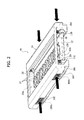
- FIG. 2 illustrates an embodiment of a module, reproduced in slightly enlarged scale
- FIGS. 3 and 4 are cross-section views of FIG. 2 .
- FIGS. 5 to 7 illustrate various details of embodiments.
- the numerical reference 10 indicates as a whole a lighting module intended to be mounted onto a rail R.
- the rail R can be for example a rail having a general C-shape with:
- Rails having the characteristics described are known and are being used in present-day technology, in a wide range of different types, and they lend themselves to being produced, for example, in the form of aluminum sections or similar.
- the rail R (to be understood in general as a component of indefinite length) can include, for example, five electrical lines W; naturally, the number of lines in question can be different.
- the module 10 can include two basic components, i.e.:
- a board 12 (for example in the form of a printed circuit board) carrying one or more light radiation sources formed, for example, by LEDs 14 , and
- a housing 16 produced, for example, from plastic material or another deformable material according to criteria better described below.
- the board 12 can be produced in the form of a printed circuit board (PCB) provided with plated holes, according to the plated through-holes printed circuit board (PTH PCB) solution.
- PCB printed circuit board
- PTH PCB plated through-holes printed circuit board
- a first face 12 a (facing upward in the appended drawings, with the exception of FIG. 5 , in which the face 12 a is instead facing downward), on which the light radiation sources 14 are fitted and on which the associated supply and driver circuits can also be fitted, which are not explicitly visible in the drawings, and
- a second face 12 b (facing downward in the appended drawings, with the exception of FIG. 5 , in which the face 12 b is instead facing upward), carrying a structure 18 with one or more electrical contacts 180 intended to cooperate—according to a general sliding-block configuration, so as to allow the module 10 to move along the rail R—with the electrical line or lines W provided on the rail.
- the contact or contacts 180 of the structure 18 can have a flexing structure, being produced for example in the form of metal strips.
- two longitudinal lateral edges can be distinguished, indicated by the label 120 .
- the housing 16 also has a channel shape which, with the module 10 mounted onto the rail R, is opposed to the C-configuration of the rail R.
- a top or web wall 16 a and two opposed side walls 16 b each of which faces one of the longitudinal edges 120 of the board 12 , can be distinguished.
- the web wall 16 a can be produced in such a way as to allow outward propagation from the module 10 of the light radiation produced by the sources 14 which are located on the board 12 .
- this result can be achieved, for example, by providing in the web wall 16 a a portion of transparent material (for example providing an insert of transparent material inserted in the housing 16 at the web wall 16 a ) or simply by producing the web wall 16 a as a windowed, i.e. open (with one or more openings), wall located at the light sources 14 .
- the side walls 16 b , or the housing 16 as a whole can be produced with an elastically deformable material (for example plastic material), so as to allow the coupling of the housing 16 (and of the module 10 as a whole) to the rail R according to snap-fit coupling methods.
- an elastically deformable material for example plastic material
- the coupling configuration can nevertheless be different and provide, for example, a frontal joint or a condition of coupling in which the side walls 16 b are coupled to the side walls R of the rail on the outside of the latter.
- the example embodiments of the drawings provide that, with the module 10 coupled to the rail R, the side walls 16 b of the housing 16 and the side walls R 2 of the rail R be substantially aligned with each other, i.e. with the module 10 not projecting laterally with respect to the rail R.
- the side walls 16 b of the housing can be provided with toothed formations 160 (see in particular the cross-section views of FIGS. 3 and 4 ) capable of clipping onto the inside of corresponding grooves made in the side walls R 2 of the rail R.
- guide members. 20 can be coupled and are likely to be produced, for example, in the form of sections with a C-shape transverse profile which “embraces” the corresponding longitudinal edge 120 of the board 12 .
- the members 20 and longitudinal edges 120 of the board 12 can be provided with complementary formations, for example openings or notches 20 a and pins 20 b which engage in these notches so as to prevent the longitudinal sliding of the guide members 20 with respect to the edges 120 .
- the guide members 20 can be separate members coupled to the longitudinal edges 120 of the board 12 . In various embodiments, it can nevertheless be possible to produce the guide members 20 as parts in one piece with the board 12 .
- each guide member 20 is extended along one of the longitudinal edges 120 of the board 12 in a position facing a corresponding side wall 16 b of the housing 16 .
- the guide members 20 and the side walls 16 b can be provided with mutually cooperating ramp-like surfaces, indicated by the labels 200 and 1600 respectively, which produce a sort of wedge coupling between, on the one hand, the board 12 , with the guide members 20 coupled to it, or produced in one piece with it, for example with the surfaces 200 forming lateral chamfering of the board 12 and, on the other hand, the housing 16 .
- the ramp-like surfaces 200 and 1600 can define, in various embodiments: each surface 200 , a surface of the respective guide member 120 facing outward and in the opposite direction to the board 12 , and
- each surface 1600 a surface of the corresponding side wall 16 b facing toward the inside of the housing 16 , toward the board 12 .
- the numerical references 30 indicate elastic elements, capable of being produced, for example, in the form of helical springs 30 worn, for example, on corresponding centering pins projecting from the web wall 16 a of the housing 16 .
- these elastic elements can be intended to act between the housing 16 and the guide members 20 (therefore in general between the housing 16 and the board 12 ) in the sense of urging the board 12 away from the web wall 16 a , therefore in a condition such that the ramp-like surfaces 200 and 1600 are forced into a condition of contact with each other.
- the wedge coupling that is elastically (pre-)charged by the elastic elements (springs) 30 ensures that, from an undeformed condition, represented in FIG. 3 , the housing 16 can be laterally compressed (making it contract), for example by acting on portions of the outer surface of the side walls 16 b made rough on the surface (see the labels 160 b in FIG. 2 ), as is schematically represented in FIG. 4 .
- the effect of the cooperation of the surfaces 200 and 1600 and their orientation ensures that this contraction (capable of being derived from the elastic deformability of the walls 16 b and/or of the housing 16 as a whole), in addition to allowing the disengaging of the side walls 16 b of the housing 16 from the side walls R 2 of the rail R, also determines a pulling of the board 12 close to the web wall 16 a against the force of the elastic elements (springs) 30 , with a resulting removal of the contact structure 18 from the bottom wall R 1 of the rail so as to disconnect (separate) the contacts 180 from the electrical lines W provided on this bottom wall.
- the module 10 can be coupled to the rail R so as to couple the side walls 16 b of the housing with the side walls R 2 of the rail.
- the housing 16 assumes the undeformed condition represented in FIG. 3 , in which the side walls 16 b of the housing 16 are coupled with the side walls R 2 of the rail R, with the toothed formations 160 (where present) which engage the abovementioned side walls R 2 and with the elastic elements 30 which urge the board 12 away from the web wall 16 a keeping the contacts 180 of the structure 18 in electrical contact with the lines W provided in the bottom wall R 1 of the rail R.
- the module 10 thus coupled to the rail R can be made to slide along the same rail by exerting on the walls 16 b a light lateral compression so as to make the coupling with the side walls R 2 of the rail less tight.
- the ramp-like shaping of the surfaces 200 and 1600 also determines as a result the moving-away of the board 12 from the bottom wall R 1 of the rail and the moving-away of the contacts 180 from the lines W, preventing, when the module 10 is sliding along the rail R, the contacts 180 from dragging against the lines W with a consequent risk of wear.
- the lateral contraction of the housing has the effect of moving the contacts 180 away from the line W breaking the electrical contact, likely to be restored only when returned to the undeformed condition of FIG. 3 .
- This allows the module 10 to be easily removed from or inserted into the rail R without needing to deactivate the electrical supply of the rail.
- FIG. 5 corresponding to an ideal view “from beneath” of the module 10 , highlights the possible presence, for example on the surface 200 , of formations so as to prevent the lateral sliding of the parts involved (surfaces 200 and 1600 ), in such a way as to ensure that the movement of the board 12 relative to the housing 16 takes place only in the direction of the board 12 moving closer to and away from the web wall 16 a .
- This can facilitate the execution of the self-centering function of the board 12 relative to the housing 16 , carried out by the ramp-like walls 200 and 1600 .
Abstract
Description
Claims (9)
Applications Claiming Priority (3)
| Application Number | Priority Date | Filing Date | Title |
|---|---|---|---|
| ITTO2011A000727 | 2011-08-04 | ||
| ITTO2011A0727 | 2011-08-04 | ||
| ITTO20110727 | 2011-08-04 |
Publications (2)
| Publication Number | Publication Date |
|---|---|
| US20130058091A1 US20130058091A1 (en) | 2013-03-07 |
| US8926134B2 true US8926134B2 (en) | 2015-01-06 |
Family
ID=44584501
Family Applications (1)
| Application Number | Title | Priority Date | Filing Date |
|---|---|---|---|
| US13/567,871 Expired - Fee Related US8926134B2 (en) | 2011-08-04 | 2012-08-06 | Lighting module for mounting onto a rail having an electrical contact |
Country Status (3)
| Country | Link |
|---|---|
| US (1) | US8926134B2 (en) |
| EP (1) | EP2557359B1 (en) |
| CN (1) | CN102913782B (en) |
Cited By (8)
| Publication number | Priority date | Publication date | Assignee | Title |
|---|---|---|---|---|
| US20150070884A1 (en) * | 2013-09-11 | 2015-03-12 | Lai-Fu Wu | Multifunctional lamp |
| US20150124463A1 (en) * | 2012-05-21 | 2015-05-07 | Osram Gmbh | Mounting device for lighting sources and associated method |
| US20160018092A1 (en) * | 2013-03-07 | 2016-01-21 | Koninklijke Philips N.V. | Lighting system, track and lighting module therefore |
| US10627082B1 (en) * | 2019-02-25 | 2020-04-21 | Eaton Intelligent Power Limited | Row mountable modular flat panel luminaire |
| US10690306B2 (en) | 2017-03-01 | 2020-06-23 | H4X E.U. | Luminaire |
| US10718498B1 (en) | 2019-02-25 | 2020-07-21 | Eaton Intelligent Power Limited | Recessed flat panel slot luminaire |
| US11004584B2 (en) * | 2018-10-17 | 2021-05-11 | Kang Yao | Electric track system for various appliances via magnetic positioning |
| US11374339B2 (en) * | 2020-09-18 | 2022-06-28 | TE Connectivity Services Gmbh | Circuit card locating features for pluggable module |
Families Citing this family (11)
| Publication number | Priority date | Publication date | Assignee | Title |
|---|---|---|---|---|
| DE102010062331B4 (en) * | 2010-12-02 | 2012-07-05 | Osram Ag | Manufacturing method for an LED lamp and a corresponding LED lamp |
| JP5945725B2 (en) * | 2012-09-13 | 2016-07-05 | パナソニックIpマネジメント株式会社 | Lighting device and lighting device unit using the same |
| DE102013207175B4 (en) * | 2013-04-19 | 2023-07-13 | Trilux Gmbh & Co. Kg | Luminaire housing corresponding to a luminaire module, luminaire and method for producing a luminaire |
| CN104696798A (en) * | 2013-12-06 | 2015-06-10 | 广东凯西欧照明有限公司 | Track lamp convenient to replace and mount |
| DE202014100951U1 (en) * | 2014-03-03 | 2015-06-09 | Zumtobel Lighting Gmbh | Luminaire with support element and releasably attachable light module |
| JP2015173084A (en) * | 2014-03-12 | 2015-10-01 | パイオニア株式会社 | Power supply device |
| DE202014101986U1 (en) * | 2014-04-28 | 2015-07-30 | Zumtobel Lighting Gmbh | Lighting system |
| US10066817B2 (en) * | 2015-03-13 | 2018-09-04 | Beta-Calco Inc. | Recessed track lighting fixture |
| TWI629434B (en) * | 2017-07-05 | 2018-07-11 | 基元高效科技有限公司 | Lamp device |
| IT201900012570A1 (en) * | 2019-07-22 | 2021-01-22 | Aec Illuminazione S R L | LED LIGHTING MODULE AND INSTALLATION SYSTEM OF THE LED BOARD OF SAID MODULE |
| KR102644955B1 (en) * | 2022-03-15 | 2024-03-07 | 온앤오프엘이디 주식회사 | LED lighting apparatus to easily attach and detach |
Citations (3)
| Publication number | Priority date | Publication date | Assignee | Title |
|---|---|---|---|---|
| EP1733653A2 (en) | 2005-06-13 | 2006-12-20 | SARNO S.p.A. | Lighting device for display cabinets and/or display areas |
| US20070285949A1 (en) | 2006-06-08 | 2007-12-13 | Ledtronics Inc. | LED track lighting system |
| DE102008017614B3 (en) | 2008-04-04 | 2009-09-17 | Insta Elektro Gmbh | lighting device |
Family Cites Families (8)
| Publication number | Priority date | Publication date | Assignee | Title |
|---|---|---|---|---|
| JP2000106027A (en) * | 1998-09-30 | 2000-04-11 | Matsushita Electric Works Ltd | Lamp socket fixing structure |
| EP1376166B1 (en) * | 2002-06-19 | 2011-05-25 | Kabushiki Kaisha Tokai-Rika-Denki-Seisakusho | Sheet-switch device |
| JP4337651B2 (en) * | 2004-06-25 | 2009-09-30 | パナソニック電工株式会社 | Spot lighting fixtures |
| US20070236946A1 (en) * | 2006-03-30 | 2007-10-11 | John Petrakis | Lighting Assembly Having An Integrated Solid-State Light Emitting Device |
| BRPI0810964B1 (en) * | 2007-05-02 | 2019-04-24 | Philips Lighting Holding B.V. | SOLID STATUS LIGHTING DEVICE |
| CN201527953U (en) * | 2009-10-22 | 2010-07-14 | 郑联盟 | Lighting tube clamping structure of spot light |
| CN201599752U (en) * | 2009-12-21 | 2010-10-06 | 东莞华明灯具有限公司 | Magnetic rail lamp |
| CN201724088U (en) * | 2010-06-12 | 2011-01-26 | 深圳市三能低碳照明有限公司 | LED street lamp capable of adjusting projection angle |
-
2012
- 2012-07-30 EP EP12178459.9A patent/EP2557359B1/en not_active Not-in-force
- 2012-08-03 CN CN201210276408.2A patent/CN102913782B/en not_active Expired - Fee Related
- 2012-08-06 US US13/567,871 patent/US8926134B2/en not_active Expired - Fee Related
Patent Citations (3)
| Publication number | Priority date | Publication date | Assignee | Title |
|---|---|---|---|---|
| EP1733653A2 (en) | 2005-06-13 | 2006-12-20 | SARNO S.p.A. | Lighting device for display cabinets and/or display areas |
| US20070285949A1 (en) | 2006-06-08 | 2007-12-13 | Ledtronics Inc. | LED track lighting system |
| DE102008017614B3 (en) | 2008-04-04 | 2009-09-17 | Insta Elektro Gmbh | lighting device |
Cited By (10)
| Publication number | Priority date | Publication date | Assignee | Title |
|---|---|---|---|---|
| US20150124463A1 (en) * | 2012-05-21 | 2015-05-07 | Osram Gmbh | Mounting device for lighting sources and associated method |
| US9541265B2 (en) * | 2012-05-21 | 2017-01-10 | Osram Gmbh | Mounting device for lighting sources and associated method |
| US20160018092A1 (en) * | 2013-03-07 | 2016-01-21 | Koninklijke Philips N.V. | Lighting system, track and lighting module therefore |
| US9810409B2 (en) * | 2013-03-07 | 2017-11-07 | Philips Lighting Holding B.V. | Lighting system, track and lighting module therefore |
| US20150070884A1 (en) * | 2013-09-11 | 2015-03-12 | Lai-Fu Wu | Multifunctional lamp |
| US10690306B2 (en) | 2017-03-01 | 2020-06-23 | H4X E.U. | Luminaire |
| US11004584B2 (en) * | 2018-10-17 | 2021-05-11 | Kang Yao | Electric track system for various appliances via magnetic positioning |
| US10627082B1 (en) * | 2019-02-25 | 2020-04-21 | Eaton Intelligent Power Limited | Row mountable modular flat panel luminaire |
| US10718498B1 (en) | 2019-02-25 | 2020-07-21 | Eaton Intelligent Power Limited | Recessed flat panel slot luminaire |
| US11374339B2 (en) * | 2020-09-18 | 2022-06-28 | TE Connectivity Services Gmbh | Circuit card locating features for pluggable module |
Also Published As
| Publication number | Publication date |
|---|---|
| CN102913782A (en) | 2013-02-06 |
| CN102913782B (en) | 2016-03-16 |
| US20130058091A1 (en) | 2013-03-07 |
| EP2557359A1 (en) | 2013-02-13 |
| EP2557359B1 (en) | 2014-07-30 |
Similar Documents
| Publication | Publication Date | Title |
|---|---|---|
| US8926134B2 (en) | Lighting module for mounting onto a rail having an electrical contact | |
| EP2615700B1 (en) | Lighting module | |
| US9894788B2 (en) | Field replaceable power supply cartridge | |
| EP3296619B1 (en) | A lighting device and corresponding fixing system | |
| JP2009199924A (en) | Illuminating device | |
| US8226280B2 (en) | LED socket assembly | |
| US8853942B1 (en) | Multiple waveguide edge lit structure | |
| CA2974291C (en) | Arrangement of multiple latching feet for an assembly, and assembly | |
| US9765952B2 (en) | Mounting device for lighting sources | |
| US20140146529A1 (en) | LED lamp fixture | |
| US20140078770A1 (en) | Warning Light Assembly | |
| WO2005099323A3 (en) | Light-emitting diode arrangement and method for the production thereof | |
| CN107002983B (en) | Luminous mechanism support for light belt lamp | |
| CN204084003U (en) | Assembly type guide rail cabinet lamp | |
| JP2012230864A (en) | Pair of sockets and lighting fixture having the same | |
| CN104235778A (en) | Lamp and installation base thereof | |
| GB2476610A (en) | Luminaires | |
| JP6444255B2 (en) | Lighting device | |
| KR200409283Y1 (en) | PCB plate with through hole for vehicle room lamp | |
| JP2016031857A (en) | Lighting fitting | |
| CN105530840A (en) | Showcase member with direct-mounted led light source | |
| JP6528235B2 (en) | LED light source unit, body unit, and LED lighting apparatus | |
| TW201509001A (en) | Electrical connection clip for board with lighting LED | |
| KR20100088372A (en) | Socket apparatus of led lamp | |
| CN205351220U (en) | Component and illumination lamps and lanterns are held to knot |
Legal Events
| Date | Code | Title | Description |
|---|---|---|---|
| AS | Assignment |
Owner name: OSRAM GMBH, GERMANY Free format text: CHANGE OF NAME;ASSIGNOR:OSRAM AG;REEL/FRAME:030452/0167 Effective date: 20121025 Owner name: OSRAM AG, GERMANY Free format text: ASSIGNMENT OF ASSIGNORS INTEREST;ASSIGNORS:HAST, MICHAEL;TREVISANELLO, LORENZO ROBERTO;ZANON, FRANCO;SIGNING DATES FROM 20120921 TO 20121023;REEL/FRAME:030443/0925 |
|
| AS | Assignment |
Owner name: OSRAM GMBH, GERMANY Free format text: CHANGE OF NAME;ASSIGNOR:OSRAM AG;REEL/FRAME:033217/0178 Effective date: 20121025 |
|
| FEPP | Fee payment procedure |
Free format text: PAYOR NUMBER ASSIGNED (ORIGINAL EVENT CODE: ASPN); ENTITY STATUS OF PATENT OWNER: LARGE ENTITY |
|
| FEPP | Fee payment procedure |
Free format text: MAINTENANCE FEE REMINDER MAILED (ORIGINAL EVENT CODE: REM.); ENTITY STATUS OF PATENT OWNER: LARGE ENTITY |
|
| LAPS | Lapse for failure to pay maintenance fees |
Free format text: PATENT EXPIRED FOR FAILURE TO PAY MAINTENANCE FEES (ORIGINAL EVENT CODE: EXP.); ENTITY STATUS OF PATENT OWNER: LARGE ENTITY |
|
| STCH | Information on status: patent discontinuation |
Free format text: PATENT EXPIRED DUE TO NONPAYMENT OF MAINTENANCE FEES UNDER 37 CFR 1.362 |
|
| FP | Lapsed due to failure to pay maintenance fee |
Effective date: 20190106 |