US8929494B2 - Systems and methods for joint beamforming and preamble detection - Google Patents
Systems and methods for joint beamforming and preamble detection Download PDFInfo
- Publication number
- US8929494B2 US8929494B2 US13/307,819 US201113307819A US8929494B2 US 8929494 B2 US8929494 B2 US 8929494B2 US 201113307819 A US201113307819 A US 201113307819A US 8929494 B2 US8929494 B2 US 8929494B2
- Authority
- US
- United States
- Prior art keywords
- rfid
- preamble
- reader system
- rfid reader
- rate
- Prior art date
- Legal status (The legal status is an assumption and is not a legal conclusion. Google has not performed a legal analysis and makes no representation as to the accuracy of the status listed.)
- Expired - Fee Related, expires
Links
Images


Classifications
-
- G—PHYSICS
- G06—COMPUTING; CALCULATING OR COUNTING
- G06K—GRAPHICAL DATA READING; PRESENTATION OF DATA; RECORD CARRIERS; HANDLING RECORD CARRIERS
- G06K7/00—Methods or arrangements for sensing record carriers, e.g. for reading patterns
- G06K7/10—Methods or arrangements for sensing record carriers, e.g. for reading patterns by electromagnetic radiation, e.g. optical sensing; by corpuscular radiation
- G06K7/10009—Methods or arrangements for sensing record carriers, e.g. for reading patterns by electromagnetic radiation, e.g. optical sensing; by corpuscular radiation sensing by radiation using wavelengths larger than 0.1 mm, e.g. radio-waves or microwaves
- G06K7/10316—Methods or arrangements for sensing record carriers, e.g. for reading patterns by electromagnetic radiation, e.g. optical sensing; by corpuscular radiation sensing by radiation using wavelengths larger than 0.1 mm, e.g. radio-waves or microwaves using at least one antenna particularly designed for interrogating the wireless record carriers
- G06K7/10356—Methods or arrangements for sensing record carriers, e.g. for reading patterns by electromagnetic radiation, e.g. optical sensing; by corpuscular radiation sensing by radiation using wavelengths larger than 0.1 mm, e.g. radio-waves or microwaves using at least one antenna particularly designed for interrogating the wireless record carriers using a plurality of antennas, e.g. configurations including means to resolve interference between the plurality of antennas
Definitions
- the present invention relates to Radio Frequency Identification (RFID) systems and more specifically to beamforming and preamble detection in RFID systems that include antenna arrays.
- RFID Radio Frequency Identification
- RFID Radio Frequency Identification
- RFID tag is typically used to refer to a technology that uses radio waves to transfer data from an electronic tag, commonly referred to as RFID tag or transponder, to a reader for the purpose of identifying and tracking an object to which the RFID tag is affixed.
- the RFID tag's information is stored electronically and the RFID tag includes a small RF transmitter and receiver.
- An RFID reader transmits an encoded radio signal to interrogate the RFID tag.
- the RFID tag receives the message and responds with its identification information.
- a class of RFID tag referred to as passive RFID tags does not use a battery. Instead, a passive RFID tag harvests energy from the transmitted RF interrogation signal and uses the harvested energy to power its electronics.
- RFID tags that include batteries are typically referred to as active RFID tags.
- EPCglobal Gen 2 UHF Class 1 Gen 2 Standard developed by EPCglobal Inc.
- EPCglobal Gen 2 UHF Class 1 Gen 2 Standard developed by EPCglobal Inc.
- ITF interrogator-talks-first
- RFID radio-frequency identification
- the EPCglobal Gen 2 standard specifies that RFID tag backscatter can use Amplitude Shift Keying (ASK) and/or Phase Shift Keying (PSK) modulation.
- ASK Amplitude Shift Keying
- PSK Phase Shift Keying
- the standard requires RFID tags to encode data using FM0 (bi-phase space) baseband or Miller modulation of a subcarrier at the data rate. Under the standard, the reader specifies the encoding to be used by the RFID tag.
- FM0 encoding inverts the baseband phase at every symbol boundary.
- a data 0 has an additional mid-symbol phase inversion.
- the EPCglobal Gen 2 standard specifies that FM0 signaling shall begin with one of a standard or an extended preamble (specified by the reader).
- Baseband Miller encoding inverts its phase between two data-0s in sequence. Baseband Miller encoding also places a phase inversion in the middle of a data-1 symbol.
- the Miller-modulated subcarrier sequences contain two, four, or eight subcarrier cycles per bit, depending on the M value specified by the reader.
- the EPCglobal Gen 2 standard specifies that Miller-modulated subcarrier signaling begin with either a standard or an extended preamble.
- the standard preamble includes a pilot tone having a duration of 4 symbol periods and the extended preamble includes a pilot tone with an additional duration of 12 symbol periods.
- One embodiment includes an antenna array comprising a plurality of antenna elements, a joint beamformer and preamble detector configured to receive inputs from each of the plurality of antenna elements, and a decoder configured to receive the resampled signal from the joint beamformer and preamble detector and to decode data using the resampled signal.
- the joint beamformer and preamble detector is configured to correlate the inputs from the plurality of antenna elements against a correlation sequence at a plurality of starting sample positions and a plurality of predetermined rates, use the correlations to select a starting sample position and rate for decoding the received signal, use the correlations to determine beamforming coefficients for combining the inputs from each of the plurality of antenna elements, and resample the combined inputs from each of the plurality of antenna elements based upon the selected starting sample position and rate.
- the RFID reader system comprises a plurality of exciters and an RFID receiver system including the antenna array, the joint beamformer and preamble detector and the decoder.
- the joint former and preamble detector comprises a skipping based correlator configured to correlate the inputs from the plurality of antenna elements against a correlation sequence at a plurality of starting sample positions and plurality of predetermined rates.
- the skipping based correlator comprises a symbol accumulator circuit and a tapped delay line, and correlations for different starting sample positions and rates can be determined using the outputs of different taps from the tapped delay line.
- the inputs from each of the plurality of antenna elements comprises samples of the in-phase and quadrature channels of each antenna element.
- the joint beamformer and preamble detector is configured to use the complex correlations of each of the antenna elements at the selected starting sample and rate to determine the beamforming coefficients.
- the joint beamformer and preamble detector is configured to determine the complex beamforming coefficient (b i ) of an antenna element i in an array of n antenna elements can be generated as follows:
- b i c i ⁇ max ⁇ ⁇ c o , ... ⁇ , c n - 1 ⁇
- c i is the complex correlation value of channel I at the selected starting sample position and rate.
- An embodiment of the method of the invention includes receiving sampled streams from each antenna element in the antenna array using the RFID receiver, correlating each stream against a predetermined correlation sequence for each of a plurality of possible starting samples and at each of a plurality of predetermined rates using the joint beamformer and preamble detector, summing the magnitude of the correlation value of each sample position and rate across each of the antenna streams using the joint beamformer and preamble detector, selecting the sample position and rate having the highest sum of correlation value magnitudes using the joint beamformer and preamble detector, determining beamforming coefficients based on the correlations of each stream at the selected sample position using the joint beamformer and preamble detector, combining the antenna outputs based upon the beamforming coefficients using the joint beamformer and preamble detector, resampling the combined antenna outputs based upon the selected starting sample and rate using the joint beamformer and preamble detector to produce a resampled signal, and decoding the transmitted data based upon the resampled signal using the RFID receiver.
- FIG. 1 conceptually illustrates an RFID reader system including a distributed exciter architecture and an RFID receiver system including a receiver antenna array in accordance with an embodiment of the invention.
- FIG. 2 conceptually illustrates an RFID receiver system including a joint beamformer and preamble detector in accordance with an embodiment of the invention.
- FIG. 3 is a block circuit diagram illustrating a joint beamformer and preamble detector configured to receive inputs from an antenna array including four antenna elements in accordance with an embodiment of the invention.
- FIGS. 4A-4C conceptually illustrate skipping based correlation in accordance with embodiments of the invention.
- FIG. 5 is a circuit diagram illustrating a circuit configured to accumulate FM0 data-0 and data-1 values in accordance with embodiments of the invention.
- FIG. 6 illustrates a tapped delay line utilized to calculate various rate correlations in accordance with embodiments of the invention.
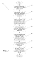
- FIG. 7 is a flow chart illustrating a process for performing joint beamforming and preamble detection in accordance with embodiments of the invention.
- an RFID reader system includes an antenna array and utilizes adaptive beamforming to achieve increased sensitivity to signals transmitted by RFID tags. Instead of conducting beamforming and preamble detection independently in a serial manner, RFID reader systems in accordance with embodiments of the invention perform joint beamforming and preamble detection. In several embodiments, preamble detection is performed on the outputs of each of the antenna elements, which finds the best starting sample and data rate for decoding the received data and generates the beamforming coefficient for combining the outputs of the antenna elements.
- a “skipping” based correlator is utilized to perform joint beamforming and preamble detection. Instead of interpolating, which utilizes multipliers, a skipping based correlator achieves fine rate correlations by skipping samples.
- RFID reader systems that perform joint beamforming and preamble detection in accordance with embodiments of the invention can provide reduced latency and increased performance relative to a system that performs beamforming and preamble detection independently.
- the use of skipping based correlators can reduce the complexity of an RFID reader system's implementation.
- RFID reader systems that perform joint beamforming and preamble detection in accordance with embodiments of the invention are discussed further below.
- a variety of RFID reader system configurations including antenna arrays can utilize joint beamformer and preamble detectors in accordance with embodiments of the invention including systems in which the RFID reader system includes a single reader that both generates interrogation signals and receives backscattered information from RFID tags and distributed RFID reader systems where a set of exciters generate interrogation signals and an RFID receiver receives backscattered information from RFID tags.
- Both RFID reader system configurations are disclosed in U.S. Pat. No. 7,633,377 entitled “RFID Receiver” to Sadr and U.S. patent application Ser. No. 12/054,331 entitled “RFID Systems Using Distributed Exciter Network” to Sadr et al.
- the disclosures of U.S. Pat. No. 7,633,377 and U.S. patent application Ser. No. 12/054,331 are incorporated by reference herein in their entirety.
- the RFID reader system 10 includes an RFID receiver system 12 connected to an antenna array 14 and a plurality of exciters 16 that are daisy chained to the RFID receiver system via cables 18 .
- the RFID receiver system is also connected to an RFID application server 20 via a network 22 .
- the plurality of exciters are shown as wired, in many embodiments exciters communicate wirelessly with the RFID receiver system.
- the RFID receiver system 12 controls the activation of exciters.
- the cable segments 18 carry both direct current (DC) power and control commands from the RFID receiver system 12 to each exciter 16 .
- the transmitted “backhaul signal” from the RFID receiver system 12 to the exciters embeds all the necessary signal characteristics and parameters to generate a desired waveform output form the exciter module to an RFID tag.
- the exciters 16 can be operated sequentially or concurrently, depending on the number of possible beams the RFID receiver system can support.
- the RFID receiver system 12 includes a single antenna array 14 and is capable of generating a single beam. In other embodiments, the RFID receiver system includes multiple antenna arrays and is capable of generating multiple beams.
- the RFID receiver system 12 receives data backscattered by RFID tags using the antenna array 14 .
- the RFID receiver system utilizes beamforming to increase the signal to noise ratio of the received signal.
- the RFID receiver also performs preamble detection to determine the data rate of the backscattered transmission and to locate the best starting sample for decoding the packet of data within the backscattered transmission.
- the data rate of RFID tags can vary considerably.
- RFID tags manufactured in accordance with the EPCglobal Gen2 specification can include rate variations of ⁇ 15%. Therefore, accurate preamble detection can significantly improve decoder performance.
- RFID receiver systems in accordance with embodiments of the invention perform joint beamforming and preamble detection, which involves performing preamble detection on each of the antenna outputs to identify the best rate and starting sample and using the information generated during the preamble detection to determine the beamforming coefficients.
- FIG. 1 a specific RFID reader system configuration is illustrated in FIG. 1 , any of a variety of RFID reader system configurations can be utilized involving receiving backscattered signals using an antenna array including (but not limited) to an RFID reader system in which the reader also generates interrogation signals in accordance with embodiments of the invention.
- Systems and methods for reading data transformed by RFID tags using joint beamforming and preamble detection in accordance with embodiments of the invention are discussed further below.
- a joint beamformer and preamble detector can be incorporated into a variety of RFID reader systems that include antenna arrays in accordance with embodiments of the invention.
- An RFID receiver system configured to decode data modulated onto signals backscattered by RFID tags using a joint beamformer and preamble detector in accordance with an embodiment of the invention is illustrated in FIG. 2 .
- the RFID receiver system 40 includes a joint beamformer and preamble detector 42 that receives as inputs the complex in-phase and quadrature (I/Q) channels of each antenna element in the antenna array.
- the antenna array includes four antenna elements. In other embodiments, any number of antenna array inputs can be processed by a joint beamformer and preamble detector in accordance with an embodiment of the invention.
- the joint beamformer and preamble detector 42 includes a preamble detector 44 , which performs preamble detection on all of the complex I/Q channels received from the antenna array.
- the preamble detector 44 determines the beamforming coefficients for combining each of the I/Q channels.
- the preamble detector 44 computes the correlation magnitude for different rates and sample positions for each I and Q channel. The correlation magnitudes for each sample position and rate are summed across all of the I and Q channels and the sample position and rate that gives the highest sum of correlation magnitudes is chosen as the best starting sample and data rate for decoding the transmitted packet. The correlations generated for each complex I/Q channel can then be utilized to generate the beamforming coefficients (see discussion below).
- the beamforming coefficients generated by the preamble detector 44 are provided to a combiner 46 and the combined signal is resampled based upon the starting sample and data rate determined by the preamble detector are provided to a decoder 48 to decode the modulated data.
- any of a variety of RFID reader systems incorporating a joint beamformer and preamble detector can be utilized in accordance with embodiments of the invention. Joint beamformer and preamble detectors in accordance with embodiments of the invention are discussed further below.
- Joint beamformer and preamble detectors in accordance with many embodiments of the invention utilize a single correlation process to both identify the best starting sample and data rate for the data backscattered by the RFID tag and determine the beamforming coefficients.
- a joint beamformer and preamble detector configured to receive complex I/Q inputs from four antenna elements in accordance with an embodiment of the invention is illustrated in FIG. 3 .
- the joint beamformer and preamble detector 60 receives incoming streams from each antenna element in the antenna array.
- the incoming data is sampled using a 16-bit analog to digital converter at 78.125 MHz with the 8 streams (i.e. 4 complex I/Q channels) time multiplexed.
- the number of incoming channels and the sampling rate of the incoming data can be determined as appropriate to the requirements of a specific application.
- the incoming data is provided to a number of rate correlators 62 , which computes the correlation values for different sample positions and different data rates using a correlation sequence that is chosen based upon the pilot and/or preamble symbols transmitted by an RFID tag.
- the rate correlator correlates the input against 28 rates that cover the ⁇ 15% variation in the data rate allowed within the EPCglobal Gen2 specification. In other embodiments, any number of rates appropriate to the requirements of a specific application can be utilized. Implementation of rate correlators in accordance with embodiments of the invention is discussed further below.
- the correlator 62 output at each of the rates is provided to circuitry 64 that selects the best position and correlation value for each rate.
- the best position and correlation value for each rate is provided to a best rate selector 66 .
- the best rate selector is circuitry configured to use the best correlation value at each rate to select the overall best starting sample and data rate.
- the best starting sample and data rate is provided to a resampler 68 to enable resampling of the combined data output generated by the adaptive beamforming circuitry within the joint beamformer and preamble detector (see discussion below).
- the best rate selector 66 also provides the best correlation values for each channel to a beamform coefficient generator 70 .
- the beamform coefficient generator generates the complex beamforming coefficients.
- the complex beamforming coefficient (b i ) of an antenna element output i in an array of n antenna elements can be generated as follows:
- b i c i ⁇ max ⁇ ⁇ c o , ... ⁇ , c n - 1 ⁇
- c i is the complex correlation value of channel i.
- the beamforming coefficients are utilized to perform adaptive beamforming on the antenna inputs.
- the incoming data for each channel is provided to a buffer write controller 72 , which writes the data for each complex channel to a separate buffer 74 .
- a combiner 76 performs complex multiplication with the buffered data and the corresponding beamforming coefficients.
- the combined data is then resampled using the best sample position and rate information determined by the best rate selector 66 and the payload data provided to a decoder. In a number of embodiments, the resampling is performed using linear interpolation. In other embodiments, any of a variety of resampling processes appropriate to a specific application can be utilized in accordance with embodiments of the invention.
- any of a variety of joint beamformer and preamble detector implementations that determine the correlation of input data with different rates and generate beamforming coefficients utilized to combine the input data can be utilized in accordance with embodiments of the invention.
- the buffer write controller 72 , buffers 74 , combiner 76 , beamform coefficient generator 70 and resampler 68 can all be implemented in a manner similar to the manner in which the equivalent components are implemented in a conventional adaptive beamformer.
- the best position selectors 64 and the best rate selector 66 can also be implemented in a similar manner to the manner in which they are implemented in a conventional preamble detector. The implementation of rate correlators in accordance with embodiments of the invention are discussed further below.
- the core of the joint beamformer and preamble detector is a rate correlator, which is capable of handling the extreme rate variations experienced in RFID systems.
- correlators are designed using interpolators.
- the incoming stream is interpolated for different rates and correlation is performed on each of the interpolated streams.
- Interpolation can be expensive to implement using devices such as Field Programmable Gate Arrays (FPGAs) due to the use of multipliers.
- FPGAs Field Programmable Gate Arrays
- a preamble detector operating on four complex channels can involve a correlator including 224 multipliers to achieve 28 rates across the ⁇ 15% rate variation experienced when using EPCglobal Gen2 compliant RFID tags.
- a “skipping” correlator is utilized to perform the rate correlations.
- a skipping correlator achieves different rates by skipping samples when performing correlation.
- the concepts underlying a skipping correlator are illustrated in FIGS. 4A-4C .
- 12 samples are correlated per symbol at a first rate equal to the sampling rate.
- two samples are skipped between each symbol resulting in a correlation for a second slower rate.
- the third example illustrated in FIG. 4C performs a correlation at a rate between the first rate and the second rate by skipping one sample in one symbol and two samples in the next symbol. Using different combinations of sample skipping across multiple symbols, very fine rate correlations are achievable.
- the following table shows a skipping scheme that can be used in a skipping correlator configured to be utilized in a joint beamformer and preamble detector similar to the one illustrated in FIG. 3 .
- 28 rate correlators cover the ⁇ 15% rate variation.
- Each rate correlator correlates 12 samples per FM0 symbol with a different number of samples skipped after each symbol, as indicated in the second column.
- the skipping sequence simply repeats every six symbols.
- the time and frequency variations are computed knowing that the nominal rate, i.e. rate variation of 0%, has 16*(125/128) 2 samples per symbol.
- Time Time Frequency Frequency Rate Variation Variation Variation Index Skipping (%) Delta (%) (%) Delta (%) 0 1, 1, 1, 1, 2, 2 ⁇ 12.62 N/A 14.44 N/A 1 1, 1, 1, 2, 2, 2, 2 ⁇ 11.53 1.09 13.03 1.41 2 1, 1, 2, 2, 2, 2 ⁇ 10.43 1.09 11.65 1.38 3 1, 2, 2, 2, 2, 2, 2 ⁇ 9.34 1.09 10.30 1.35 4 2, 2, 2, 2, 2, 2, 2 ⁇ 8.25 1.09 8.99 1.31 5 2, 2, 2, 2, 2, 2, 3 ⁇ 7.16 1.09 7.71 1.28 6 2, 2, 2, 2, 2, 3, 3 ⁇ 6.07 1.09 6.46 1.25 7 2, 2, 2, 3, 3, 3 ⁇ 4.97 1.09 5.23 1.22 8 2, 2, 3, 3, 3, 3, 3 ⁇ 3.88 1.09 4.04 1.20 9 2, 3, 3, 3, 3, 3 ⁇ 2.79 1.09 2.87 1.17 10 3, 3, 3, 3, 3 ⁇ 1.70 1.09 1.72 1.14 11 3, 3, 3, 3, 3, 3, 4 ⁇ 0.60 1.09 0.61 1.12 12
- skipping based rate correlators are discussed above, any correlator including an interpolation based correlator can be utilized as appropriate to the requirements of a specific application in accordance with embodiments of the invention.
- the use of the skipping correlator discussed above in joint beamforming and preamble detection of data encoded in accordance with the EPCglobal Gen2 specification is discussed further below.
- the EPCglobal Gen2 specification enables an RFID reader system to specify the encoding utilized by an RFID tag.
- the rate correlator utilizes the portion of the Miller-2 pilot and preamble that corresponds to the latter 20 FM0 symbols as the correlation sequence.
- the portion of the Miller-4 pilot and preamble corresponding to the latter 40 FM0 symbols can be utilized as the correlation sequence and the portion of the Miller-8 pilot and preamble corresponding to the latter 48 FM0 symbols can be utilized as the correlation sequence.
- specific portions of the pilot and preamble are indicated above, any portion appropriate to a specific application can be utilized by a rate correlator as a correlation sequence in accordance with embodiments of the invention.
- the initial step in performing the correlation is to accumulate FM0 data-0 or data-1 symbols (i.e. 12 samples with a transition in the middle or without a transition).
- a circuit that can be utilized to accumulate FM0 data-0 and data-1 symbols in accordance with embodiments of the invention is illustrated in FIG. 5 .
- the first part of the circuit computes the half symbol accumulations and the latter part uses the half symbol accumulations to generate a zero or a one accumulation.
- the y output is capable of generating either data-0 or data-1s depending on the sign of the operand, and the z output generates data-0s only.
- a circuit for computing different correlation values by summing different delayed versions of the y and z outputs in accordance with embodiments of the invention is illustrated in FIG.
- the y and z outputs simply enter a long chain of shift registers from which different taps are taken.
- the taps that are taken to determine the correlation at a specific data rate are a function of the modulation type and skipping pattern for the particular rate. Depending upon the modulation type, some taps are negated (to obtain an inverse data-0 or a data-1) or are reset (to discard taps that are not needed).
- the resulting values can be summed using any of a variety of techniques to obtain the correlation at each of the rates. As discussed above, the correlations can then be utilized to determine the best starting sample and rate and the beamforming coefficients utilized to combine the data from each of the antenna elements.
- FIG. 7 A process for performing joint beamforming and preamble detection in accordance with an embodiment of the invention is illustrated in FIG. 7 .
- the process 80 involves receiving ( 82 ) oversampled I and Q streams from each of the antenna elements in an antenna array. Each of the streams is correlated ( 84 ) against a correlation sequence for a plurality of potential starting samples and predetermined data rates. The magnitudes of the resulting correlations are summed ( 86 ) across each of the streams for each starting sample position and data rate.
- the starting sample position and data rate with the highest sum is selected ( 88 ) as the best starting sample and data rate for decoding the received data.
- the correlations for each of the streams at the selected starting sample and data rate can be used to determine ( 90 ) beamforming coefficients for combining ( 92 ) the complex outputs of each of the antenna elements.
- the beamforming coefficient is determined as the ratio of the complex correlation of a particular antenna element relative to the maximum complex correlation across all of the antenna elements at the selected starting sample and data rate.
- any of a variety of processes involving using a single correlation process to both identify the best starting sample and data rate for decoding the received data and the beamforming coefficients that can be used to combine the complex antenna outputs can be utilized in accordance with embodiments of the invention.
Abstract
Description
where ci is the complex correlation value of channel I at the selected starting sample position and rate.
| TABLE 1 |
| Skipping sequences used for different rate correlators. |
| Time | Time | Frequency | Frequency | ||
| Rate | Variation | Variation | Variation | Variation | |
| Index | Skipping | (%) | Delta (%) | (%) | Delta (%) |
| 0 | 1, 1, 1, 1, 2, 2 | −12.62 | N/A | 14.44 | N/A |
| 1 | 1, 1, 1, 2, 2, 2 | −11.53 | 1.09 | 13.03 | 1.41 |
| 2 | 1, 1, 2, 2, 2, 2 | −10.43 | 1.09 | 11.65 | 1.38 |
| 3 | 1, 2, 2, 2, 2, 2 | −9.34 | 1.09 | 10.30 | 1.35 |
| 4 | 2, 2, 2, 2, 2, 2 | −8.25 | 1.09 | 8.99 | 1.31 |
| 5 | 2, 2, 2, 2, 2, 3 | −7.16 | 1.09 | 7.71 | 1.28 |
| 6 | 2, 2, 2, 2, 3, 3 | −6.07 | 1.09 | 6.46 | 1.25 |
| 7 | 2, 2, 2, 3, 3, 3 | −4.97 | 1.09 | 5.23 | 1.22 |
| 8 | 2, 2, 3, 3, 3, 3 | −3.88 | 1.09 | 4.04 | 1.20 |
| 9 | 2, 3, 3, 3, 3, 3 | −2.79 | 1.09 | 2.87 | 1.17 |
| 10 | 3, 3, 3, 3, 3, 3 | −1.70 | 1.09 | 1.72 | 1.14 |
| 11 | 3, 3, 3, 3, 3, 4 | −0.60 | 1.09 | 0.61 | 1.12 |
| 12 | 3, 3, 3, 3, 4, 4 | 0.49 | 1.09 | −0.49 | 1.09 |
| 13 | 3, 3, 3, 4, 4, 4 | 1.58 | 1.09 | −1.56 | 1.07 |
| 14 | 3, 3, 4, 4, 4, 4 | 2.67 | 1.09 | −2.60 | 1.05 |
| 15 | 3, 4, 4, 4, 4, 4 | 3.77 | 1.09 | −3.63 | 1.03 |
| 16 | 4, 4, 4, 4, 4, 4 | 4.86 | 1.09 | −4.63 | 1.00 |
| 17 | 4, 4, 4, 4, 4, 5 | 5.95 | 1.09 | −5.62 | 0.98 |
| 18 | 4, 4, 4, 4, 5, 5 | 7.04 | 1.09 | −6.58 | 0.96 |
| 19 | 4, 4, 4, 5, 5, 5 | 8.13 | 1.09 | −7.52 | 0.94 |
| 20 | 4, 4, 5, 5, 5, 5 | 9.23 | 1.09 | −8.45 | 0.92 |
| 21 | 4, 5, 5, 5, 5, 5 | 10.32 | 1.09 | −9.35 | 0.91 |
| 22 | 5, 5, 5, 5, 5, 5 | 11.41 | 1.09 | −10.24 | 0.89 |
| 23 | 5, 5, 5, 5, 5, 6 | 12.50 | 1.09 | −11.11 | 0.87 |
| 24 | 5, 5, 5, 5, 6, 6 | 13.60 | 1.09 | −11.97 | 0.85 |
| 25 | 5, 5, 5, 6, 6, 6 | 14.69 | 1.09 | −12.81 | 0.84 |
| 26 | 5, 5, 6, 6, 6, 6 | 15.78 | 1.09 | −13.63 | 0.82 |
| 27 | 5, 6, 6, 6, 6, 6 | 16.87 | 1.09 | −14.44 | 0.81 |
Claims (16)
Priority Applications (2)
| Application Number | Priority Date | Filing Date | Title |
|---|---|---|---|
| US13/307,819 US8929494B2 (en) | 2010-11-30 | 2011-11-30 | Systems and methods for joint beamforming and preamble detection |
| US14/575,975 US9268981B2 (en) | 2010-11-30 | 2014-12-18 | Systems and methods for joint beamforming and preamble detection |
Applications Claiming Priority (2)
| Application Number | Priority Date | Filing Date | Title |
|---|---|---|---|
| US41812010P | 2010-11-30 | 2010-11-30 | |
| US13/307,819 US8929494B2 (en) | 2010-11-30 | 2011-11-30 | Systems and methods for joint beamforming and preamble detection |
Related Child Applications (1)
| Application Number | Title | Priority Date | Filing Date |
|---|---|---|---|
| US14/575,975 Continuation US9268981B2 (en) | 2010-11-30 | 2014-12-18 | Systems and methods for joint beamforming and preamble detection |
Publications (2)
| Publication Number | Publication Date |
|---|---|
| US20120188058A1 US20120188058A1 (en) | 2012-07-26 |
| US8929494B2 true US8929494B2 (en) | 2015-01-06 |
Family
ID=46543764
Family Applications (2)
| Application Number | Title | Priority Date | Filing Date |
|---|---|---|---|
| US13/307,819 Expired - Fee Related US8929494B2 (en) | 2010-11-30 | 2011-11-30 | Systems and methods for joint beamforming and preamble detection |
| US14/575,975 Expired - Fee Related US9268981B2 (en) | 2010-11-30 | 2014-12-18 | Systems and methods for joint beamforming and preamble detection |
Family Applications After (1)
| Application Number | Title | Priority Date | Filing Date |
|---|---|---|---|
| US14/575,975 Expired - Fee Related US9268981B2 (en) | 2010-11-30 | 2014-12-18 | Systems and methods for joint beamforming and preamble detection |
Country Status (1)
| Country | Link |
|---|---|
| US (2) | US8929494B2 (en) |
Cited By (4)
| Publication number | Priority date | Publication date | Assignee | Title |
|---|---|---|---|---|
| US9268981B2 (en) * | 2010-11-30 | 2016-02-23 | Mojix, Inc. | Systems and methods for joint beamforming and preamble detection |
| US20160308599A1 (en) * | 2013-12-04 | 2016-10-20 | Teknologian Tutkimuskeskus Vtt Oy | Decoupling Antenna Elements |
| US9729119B1 (en) * | 2016-03-04 | 2017-08-08 | Atmel Corporation | Automatic gain control for received signal strength indication |
| US20200220707A1 (en) * | 2019-01-09 | 2020-07-09 | Electronics And Telecommunications Research Institute | Method and apparatus for backscatter communication of pattern-based demodulation |
Families Citing this family (21)
| Publication number | Priority date | Publication date | Assignee | Title |
|---|---|---|---|---|
| US8064408B2 (en) | 2008-02-20 | 2011-11-22 | Hobbit Wave | Beamforming devices and methods |
| US10447094B2 (en) * | 2016-05-03 | 2019-10-15 | Origin Wireless, Inc. | Method, system, and apparatus for wireless power transmission based on power waveforming |
| US9780435B2 (en) | 2011-12-05 | 2017-10-03 | Adasa Inc. | Aerial inventory antenna |
| US10476130B2 (en) | 2011-12-05 | 2019-11-12 | Adasa Inc. | Aerial inventory antenna |
| US10050330B2 (en) | 2011-12-05 | 2018-08-14 | Adasa Inc. | Aerial inventory antenna |
| US10846497B2 (en) | 2011-12-05 | 2020-11-24 | Adasa Inc. | Holonomic RFID reader |
| US11093722B2 (en) | 2011-12-05 | 2021-08-17 | Adasa Inc. | Holonomic RFID reader |
| US9747480B2 (en) | 2011-12-05 | 2017-08-29 | Adasa Inc. | RFID and robots for multichannel shopping |
| US8690057B2 (en) | 2012-03-06 | 2014-04-08 | A-I Packaging Solutions, Inc. | Radio frequency identification system for tracking and managing materials in a manufacturing process |
| US9154353B2 (en) | 2012-03-07 | 2015-10-06 | Hobbit Wave, Inc. | Devices and methods using the hermetic transform for transmitting and receiving signals using OFDM |
| WO2013134506A2 (en) | 2012-03-07 | 2013-09-12 | Hobbit Wave, Inc. | Devices and methods using the hermetic transform |
| US9531431B2 (en) | 2013-10-25 | 2016-12-27 | Hobbit Wave, Inc. | Devices and methods employing hermetic transforms for encoding and decoding digital information in spread-spectrum communications systems |
| US9829568B2 (en) | 2013-11-22 | 2017-11-28 | VertoCOMM, Inc. | Radar using hermetic transforms |
| US11304661B2 (en) | 2014-10-23 | 2022-04-19 | VertoCOMM, Inc. | Enhanced imaging devices, and image construction methods and processes employing hermetic transforms |
| US9871684B2 (en) | 2014-11-17 | 2018-01-16 | VertoCOMM, Inc. | Devices and methods for hermetic transform filters |
| US10305717B2 (en) | 2016-02-26 | 2019-05-28 | VertoCOMM, Inc. | Devices and methods using the hermetic transform for transmitting and receiving signals using multi-channel signaling |
| EP3226499B1 (en) * | 2016-03-31 | 2019-09-04 | Intel IP Corporation | Apparatuses and methods for generating a second digital signal based on a first digital signal |
| FR3055461B1 (en) * | 2016-08-23 | 2018-08-31 | STMicroelectronics (Alps) SAS | METHOD FOR PROCESSING SIGNALS, ESPECIALLY ACOUSTIC SIGNALS, AND CORRESPONDING DEVICE |
| US11023851B2 (en) | 2018-03-30 | 2021-06-01 | A-1 Packaging Solutions, Inc. | RFID-based inventory tracking system |
| US11348067B2 (en) | 2018-03-30 | 2022-05-31 | A-1 Packaging Solutions, Inc. | RFID-based inventory tracking system |
| WO2020219537A1 (en) | 2019-04-22 | 2020-10-29 | A-1 Packaging Solutions, Inc. | Rfid-based inventory tracking system |
Citations (23)
| Publication number | Priority date | Publication date | Assignee | Title |
|---|---|---|---|---|
| US6127981A (en) | 1995-10-13 | 2000-10-03 | Lockheed Martin Corporation | Phased array antenna for radio frequency identification |
| US6184841B1 (en) | 1996-12-31 | 2001-02-06 | Lucent Technologies Inc. | Antenna array in an RFID system |
| US6396438B1 (en) | 1999-09-24 | 2002-05-28 | Slc Technologies | System and method for locating radio frequency identification tags using three-phase antenna |
| US6903656B1 (en) | 2003-05-27 | 2005-06-07 | Applied Wireless Identifications Group, Inc. | RFID reader with multiple antenna selection and automated antenna matching |
| US20050237953A1 (en) | 2000-06-06 | 2005-10-27 | Carrender Curtis L | Distance/ranging determination using relative phase data |
| US6982670B2 (en) | 2003-06-04 | 2006-01-03 | Farrokh Mohamadi | Phase management for beam-forming applications |
| US7002461B2 (en) | 2001-08-09 | 2006-02-21 | Edgar Alan Duncan | Passive RFID transponder/machine-mounted antenna and reader system and method for hidden obstacle detection and avoidance |
| US20060117066A1 (en) * | 2003-11-07 | 2006-06-01 | Smith John S | RFID handshaking |
| US20060279458A1 (en) | 2004-06-03 | 2006-12-14 | Farrokh Mohamadi | RFID reader and active tag |
| US20070025475A1 (en) * | 2005-07-28 | 2007-02-01 | Symbol Technologies, Inc. | Method and apparatus for data signal processing in wireless RFID systems |
| US20070069864A1 (en) * | 2005-09-29 | 2007-03-29 | Ji-Hoon Bae | Apparatus and method for receiving tag signal in mobile RFID reader |
| US7212116B2 (en) | 2003-12-10 | 2007-05-01 | Motia, Inc. | RFID system with an adaptive array antenna |
| US20070096873A1 (en) | 2005-10-28 | 2007-05-03 | Ramin Sadr | Rfid receiver |
| US20080012710A1 (en) * | 2006-07-11 | 2008-01-17 | Ramin Sadr | Rfid beam forming system |
| US20080042847A1 (en) | 2006-08-14 | 2008-02-21 | Allen Hollister | Method for reading RFID tags using directional antennas |
| US7432874B2 (en) | 2004-07-22 | 2008-10-07 | Feig Electronic Gmbh | Antenna array |
| US20090146792A1 (en) | 2007-03-23 | 2009-06-11 | Ramin Sadr | Rfid systems using distributed exciter network |
| US7561053B2 (en) | 2005-08-10 | 2009-07-14 | Cias, Inc. | Sequenced antenna array for determining where gaming chips with embedded RFID tags are located on a blackjack, poker or other gaming table and for myriad other RFID applications |
| US7652577B1 (en) | 2006-02-04 | 2010-01-26 | Checkpoint Systems, Inc. | Systems and methods of beamforming in radio frequency identification applications |
| US20100026496A1 (en) * | 2007-01-23 | 2010-02-04 | Tallinn University Of Technology | Method and device for synchronization of a decoder of a rfid receiver |
| US20100039228A1 (en) * | 2008-04-14 | 2010-02-18 | Ramin Sadr | Radio frequency identification tag location estimation and tracking system and method |
| US7667652B2 (en) * | 2006-07-11 | 2010-02-23 | Mojix, Inc. | RFID antenna system |
| US8325014B1 (en) * | 2008-09-29 | 2012-12-04 | Impinj, Inc. | RFID readers mitigating colored noise |
Family Cites Families (1)
| Publication number | Priority date | Publication date | Assignee | Title |
|---|---|---|---|---|
| US8929494B2 (en) | 2010-11-30 | 2015-01-06 | Mojix, Inc. | Systems and methods for joint beamforming and preamble detection |
-
2011
- 2011-11-30 US US13/307,819 patent/US8929494B2/en not_active Expired - Fee Related
-
2014
- 2014-12-18 US US14/575,975 patent/US9268981B2/en not_active Expired - Fee Related
Patent Citations (26)
| Publication number | Priority date | Publication date | Assignee | Title |
|---|---|---|---|---|
| US6127981A (en) | 1995-10-13 | 2000-10-03 | Lockheed Martin Corporation | Phased array antenna for radio frequency identification |
| US6184841B1 (en) | 1996-12-31 | 2001-02-06 | Lucent Technologies Inc. | Antenna array in an RFID system |
| US6396438B1 (en) | 1999-09-24 | 2002-05-28 | Slc Technologies | System and method for locating radio frequency identification tags using three-phase antenna |
| US20050237953A1 (en) | 2000-06-06 | 2005-10-27 | Carrender Curtis L | Distance/ranging determination using relative phase data |
| US7002461B2 (en) | 2001-08-09 | 2006-02-21 | Edgar Alan Duncan | Passive RFID transponder/machine-mounted antenna and reader system and method for hidden obstacle detection and avoidance |
| US6903656B1 (en) | 2003-05-27 | 2005-06-07 | Applied Wireless Identifications Group, Inc. | RFID reader with multiple antenna selection and automated antenna matching |
| US6982670B2 (en) | 2003-06-04 | 2006-01-03 | Farrokh Mohamadi | Phase management for beam-forming applications |
| US20060117066A1 (en) * | 2003-11-07 | 2006-06-01 | Smith John S | RFID handshaking |
| US7212116B2 (en) | 2003-12-10 | 2007-05-01 | Motia, Inc. | RFID system with an adaptive array antenna |
| US20060279458A1 (en) | 2004-06-03 | 2006-12-14 | Farrokh Mohamadi | RFID reader and active tag |
| US7432855B2 (en) | 2004-06-03 | 2008-10-07 | Farrokh Mohamadi | RFID reader and active tag |
| US7432874B2 (en) | 2004-07-22 | 2008-10-07 | Feig Electronic Gmbh | Antenna array |
| US20070025475A1 (en) * | 2005-07-28 | 2007-02-01 | Symbol Technologies, Inc. | Method and apparatus for data signal processing in wireless RFID systems |
| US7561053B2 (en) | 2005-08-10 | 2009-07-14 | Cias, Inc. | Sequenced antenna array for determining where gaming chips with embedded RFID tags are located on a blackjack, poker or other gaming table and for myriad other RFID applications |
| US20070069864A1 (en) * | 2005-09-29 | 2007-03-29 | Ji-Hoon Bae | Apparatus and method for receiving tag signal in mobile RFID reader |
| US20070096873A1 (en) | 2005-10-28 | 2007-05-03 | Ramin Sadr | Rfid receiver |
| US7633377B2 (en) | 2005-10-28 | 2009-12-15 | Mojix, Inc. | RFID receiver |
| US7652577B1 (en) | 2006-02-04 | 2010-01-26 | Checkpoint Systems, Inc. | Systems and methods of beamforming in radio frequency identification applications |
| US20080012710A1 (en) * | 2006-07-11 | 2008-01-17 | Ramin Sadr | Rfid beam forming system |
| US7667652B2 (en) * | 2006-07-11 | 2010-02-23 | Mojix, Inc. | RFID antenna system |
| US20080042847A1 (en) | 2006-08-14 | 2008-02-21 | Allen Hollister | Method for reading RFID tags using directional antennas |
| US20100026496A1 (en) * | 2007-01-23 | 2010-02-04 | Tallinn University Of Technology | Method and device for synchronization of a decoder of a rfid receiver |
| US20090146792A1 (en) | 2007-03-23 | 2009-06-11 | Ramin Sadr | Rfid systems using distributed exciter network |
| US8395482B2 (en) | 2007-03-23 | 2013-03-12 | Mojix, Inc. | RFID systems using distributed exciter network |
| US20100039228A1 (en) * | 2008-04-14 | 2010-02-18 | Ramin Sadr | Radio frequency identification tag location estimation and tracking system and method |
| US8325014B1 (en) * | 2008-09-29 | 2012-12-04 | Impinj, Inc. | RFID readers mitigating colored noise |
Cited By (8)
| Publication number | Priority date | Publication date | Assignee | Title |
|---|---|---|---|---|
| US9268981B2 (en) * | 2010-11-30 | 2016-02-23 | Mojix, Inc. | Systems and methods for joint beamforming and preamble detection |
| US20160308599A1 (en) * | 2013-12-04 | 2016-10-20 | Teknologian Tutkimuskeskus Vtt Oy | Decoupling Antenna Elements |
| US10516467B2 (en) * | 2013-12-04 | 2019-12-24 | Teknologian Tutkimuskeskus Vtt Oy | Decoupling antenna elements |
| US9729119B1 (en) * | 2016-03-04 | 2017-08-08 | Atmel Corporation | Automatic gain control for received signal strength indication |
| US20180041179A1 (en) * | 2016-03-04 | 2018-02-08 | Atmel Corporation | Automatic Gain Control for Received Signal Strength Indication |
| US10158336B2 (en) * | 2016-03-04 | 2018-12-18 | Atmel Corporation | Automatic gain control for received signal strength indication |
| US20200220707A1 (en) * | 2019-01-09 | 2020-07-09 | Electronics And Telecommunications Research Institute | Method and apparatus for backscatter communication of pattern-based demodulation |
| US10944539B2 (en) * | 2019-01-09 | 2021-03-09 | Electronics And Telecommunications Research Institute | Method and apparatus for backscatter communication of pattern-based demodulation |
Also Published As
| Publication number | Publication date |
|---|---|
| US9268981B2 (en) | 2016-02-23 |
| US20150102912A1 (en) | 2015-04-16 |
| US20120188058A1 (en) | 2012-07-26 |
Similar Documents
| Publication | Publication Date | Title |
|---|---|---|
| US9268981B2 (en) | Systems and methods for joint beamforming and preamble detection | |
| CN108594233B (en) | Speed ambiguity resolving method based on MIMO automobile radar | |
| KR102202600B1 (en) | Apparatus and method for forming beam for radar signal processing | |
| US9966989B2 (en) | Array antenna system and spread spectrum beamformer method | |
| US7602293B2 (en) | Interrogator for RFID tag | |
| KR100444822B1 (en) | Apparatus for Calibration in Adaptive Array Antenna and Method Thereof | |
| Mishra et al. | A cognitive sub-Nyquist MIMO radar prototype | |
| US6529745B1 (en) | Radio wave arrival direction estimating antenna apparatus | |
| CN101416416B (en) | Adaptive beam-steering methods to maximize wireless link budget and reduce delay-spread using multiple transmit and receive antennas | |
| US6850190B2 (en) | Combined beamforming-diversity wireless fading channel demodulator using adaptive sub-array group antennas, signal receiving system and method for mobile communications | |
| US20050269408A1 (en) | RFID joint acquisition of time sync and timebase | |
| US8195098B2 (en) | Method for beamforming training and communications apparatuses utilizing the same | |
| US7477192B1 (en) | Direction finding system and method | |
| US20070224942A1 (en) | Radio-Frequency Receiver Device | |
| CN114325679A (en) | Perception communication integration method based on time delay Doppler domain signal processing | |
| US20070111692A1 (en) | Radio-frequency receiver device, radio-frequency communication device, and interrogator | |
| US7339979B1 (en) | Adaptive beamforming methods and systems that enhance performance and reduce computations | |
| JP4392109B2 (en) | Direction of arrival estimation device | |
| CN109327249A (en) | Angle-of- arrival estimation method in mimo system | |
| WO2009076223A1 (en) | Transforming signals using passive circuits | |
| US20060215740A1 (en) | Receiving device and signal demodulating method | |
| US11431400B2 (en) | Method and apparatus for forming a plurality of beamformed signals using a plurality of received signals | |
| US20070155192A1 (en) | Module and method for estimating signal direction of arrival | |
| CN114731182A (en) | Method and system for generating at least one backscatter region of an ambient signal and/or for receiving a backscatter ambient signal | |
| Galler et al. | SDR based EPC UHF RFID reader DS-SS localization testbed |
Legal Events
| Date | Code | Title | Description |
|---|---|---|---|
| AS | Assignment |
Owner name: MOJIX, INC., CALIFORNIA Free format text: ASSIGNMENT OF ASSIGNORS INTEREST;ASSIGNORS:LEE, DONG-U;JONES, CHRISTOPHER;REEL/FRAME:028021/0819 Effective date: 20120404 |
|
| AS | Assignment |
Owner name: SQUARE 1 BANK, NORTH CAROLINA Free format text: SECURITY AGREEMENT;ASSIGNOR:MOJIX, INC.;REEL/FRAME:031031/0479 Effective date: 20130520 |
|
| STCF | Information on status: patent grant |
Free format text: PATENTED CASE |
|
| AS | Assignment |
Owner name: GSV GROWTH CREDIT FUND INC., CALIFORNIA Free format text: SECURITY INTEREST;ASSIGNORS:MOJIX, INC.;TIERCONNECT, INC.;REEL/FRAME:042400/0539 Effective date: 20170516 |
|
| AS | Assignment |
Owner name: MOJIX, INC., CALIFORNIA Free format text: RELEASE BY SECURED PARTY;ASSIGNOR:PACIFIC WESTERN BANK;REEL/FRAME:042672/0241 Effective date: 20170531 |
|
| FEPP | Fee payment procedure |
Free format text: MAINTENANCE FEE REMINDER MAILED (ORIGINAL EVENT CODE: REM.); ENTITY STATUS OF PATENT OWNER: SMALL ENTITY |
|
| FEPP | Fee payment procedure |
Free format text: SURCHARGE FOR LATE PAYMENT, SMALL ENTITY (ORIGINAL EVENT CODE: M2554); ENTITY STATUS OF PATENT OWNER: SMALL ENTITY |
|
| MAFP | Maintenance fee payment |
Free format text: PAYMENT OF MAINTENANCE FEE, 4TH YR, SMALL ENTITY (ORIGINAL EVENT CODE: M2551); ENTITY STATUS OF PATENT OWNER: SMALL ENTITY Year of fee payment: 4 |
|
| AS | Assignment |
Owner name: TIERCONNECT, INC., CALIFORNIA Free format text: RELEASE BY SECURED PARTY;ASSIGNOR:RUNWAY GROWTH FINANCE CORP. (FORMERLY KNOWN AS GSV GROWTH CREDIT FUND INC.);REEL/FRAME:060312/0325 Effective date: 20220505 Owner name: MOJIX, INC., CALIFORNIA Free format text: RELEASE BY SECURED PARTY;ASSIGNOR:RUNWAY GROWTH FINANCE CORP. (FORMERLY KNOWN AS GSV GROWTH CREDIT FUND INC.);REEL/FRAME:060312/0325 Effective date: 20220505 |
|
| FEPP | Fee payment procedure |
Free format text: MAINTENANCE FEE REMINDER MAILED (ORIGINAL EVENT CODE: REM.); ENTITY STATUS OF PATENT OWNER: SMALL ENTITY |
|
| AS | Assignment |
Owner name: SUSSER BANK, TEXAS Free format text: SECURITY INTEREST;ASSIGNOR:MOJIX, INC.;REEL/FRAME:061358/0966 Effective date: 20221007 |
|
| LAPS | Lapse for failure to pay maintenance fees |
Free format text: PATENT EXPIRED FOR FAILURE TO PAY MAINTENANCE FEES (ORIGINAL EVENT CODE: EXP.); ENTITY STATUS OF PATENT OWNER: SMALL ENTITY |
|
| STCH | Information on status: patent discontinuation |
Free format text: PATENT EXPIRED DUE TO NONPAYMENT OF MAINTENANCE FEES UNDER 37 CFR 1.362 |
|
| FP | Lapsed due to failure to pay maintenance fee |
Effective date: 20230106 |