US8930029B2 - Methods and apparatus for differential energy based airside economizer changeover - Google Patents
Methods and apparatus for differential energy based airside economizer changeover Download PDFInfo
- Publication number
- US8930029B2 US8930029B2 US14/246,308 US201414246308A US8930029B2 US 8930029 B2 US8930029 B2 US 8930029B2 US 201414246308 A US201414246308 A US 201414246308A US 8930029 B2 US8930029 B2 US 8930029B2
- Authority
- US
- United States
- Prior art keywords
- air
- dry
- air source
- enthalpy
- economizer
- Prior art date
- Legal status (The legal status is an assumption and is not a legal conclusion. Google has not performed a legal analysis and makes no representation as to the accuracy of the status listed.)
- Active
Links
Images


Classifications
-
- F—MECHANICAL ENGINEERING; LIGHTING; HEATING; WEAPONS; BLASTING
- F24—HEATING; RANGES; VENTILATING
- F24F—AIR-CONDITIONING; AIR-HUMIDIFICATION; VENTILATION; USE OF AIR CURRENTS FOR SCREENING
- F24F11/00—Control or safety arrangements
- F24F11/0008—Control or safety arrangements for air-humidification
-
- F24F11/0015—
-
- F24F11/006—
-
- F—MECHANICAL ENGINEERING; LIGHTING; HEATING; WEAPONS; BLASTING
- F24—HEATING; RANGES; VENTILATING
- F24F—AIR-CONDITIONING; AIR-HUMIDIFICATION; VENTILATION; USE OF AIR CURRENTS FOR SCREENING
- F24F11/00—Control or safety arrangements
- F24F11/30—Control or safety arrangements for purposes related to the operation of the system, e.g. for safety or monitoring
-
- F—MECHANICAL ENGINEERING; LIGHTING; HEATING; WEAPONS; BLASTING
- F24—HEATING; RANGES; VENTILATING
- F24F—AIR-CONDITIONING; AIR-HUMIDIFICATION; VENTILATION; USE OF AIR CURRENTS FOR SCREENING
- F24F11/00—Control or safety arrangements
- F24F11/62—Control or safety arrangements characterised by the type of control or by internal processing, e.g. using fuzzy logic, adaptive control or estimation of values
-
- F—MECHANICAL ENGINEERING; LIGHTING; HEATING; WEAPONS; BLASTING
- F24—HEATING; RANGES; VENTILATING
- F24F—AIR-CONDITIONING; AIR-HUMIDIFICATION; VENTILATION; USE OF AIR CURRENTS FOR SCREENING
- F24F7/00—Ventilation
- F24F7/04—Ventilation with ducting systems, e.g. by double walls; with natural circulation
- F24F7/06—Ventilation with ducting systems, e.g. by double walls; with natural circulation with forced air circulation, e.g. by fan positioning of a ventilator in or against a conduit
- F24F7/08—Ventilation with ducting systems, e.g. by double walls; with natural circulation with forced air circulation, e.g. by fan positioning of a ventilator in or against a conduit with separate ducts for supplied and exhausted air with provisions for reversal of the input and output systems
-
- G—PHYSICS
- G05—CONTROLLING; REGULATING
- G05B—CONTROL OR REGULATING SYSTEMS IN GENERAL; FUNCTIONAL ELEMENTS OF SUCH SYSTEMS; MONITORING OR TESTING ARRANGEMENTS FOR SUCH SYSTEMS OR ELEMENTS
- G05B13/00—Adaptive control systems, i.e. systems automatically adjusting themselves to have a performance which is optimum according to some preassigned criterion
- G05B13/02—Adaptive control systems, i.e. systems automatically adjusting themselves to have a performance which is optimum according to some preassigned criterion electric
- G05B13/0205—Adaptive control systems, i.e. systems automatically adjusting themselves to have a performance which is optimum according to some preassigned criterion electric not using a model or a simulator of the controlled system
- G05B13/024—Adaptive control systems, i.e. systems automatically adjusting themselves to have a performance which is optimum according to some preassigned criterion electric not using a model or a simulator of the controlled system in which a parameter or coefficient is automatically adjusted to optimise the performance
-
- F—MECHANICAL ENGINEERING; LIGHTING; HEATING; WEAPONS; BLASTING
- F24—HEATING; RANGES; VENTILATING
- F24F—AIR-CONDITIONING; AIR-HUMIDIFICATION; VENTILATION; USE OF AIR CURRENTS FOR SCREENING
- F24F11/00—Control or safety arrangements
- F24F11/30—Control or safety arrangements for purposes related to the operation of the system, e.g. for safety or monitoring
- F24F11/46—Improving electric energy efficiency or saving
-
- F—MECHANICAL ENGINEERING; LIGHTING; HEATING; WEAPONS; BLASTING
- F24—HEATING; RANGES; VENTILATING
- F24F—AIR-CONDITIONING; AIR-HUMIDIFICATION; VENTILATION; USE OF AIR CURRENTS FOR SCREENING
- F24F11/00—Control or safety arrangements
- F24F11/62—Control or safety arrangements characterised by the type of control or by internal processing, e.g. using fuzzy logic, adaptive control or estimation of values
- F24F11/63—Electronic processing
- F24F11/65—Electronic processing for selecting an operating mode
-
- F—MECHANICAL ENGINEERING; LIGHTING; HEATING; WEAPONS; BLASTING
- F24—HEATING; RANGES; VENTILATING
- F24F—AIR-CONDITIONING; AIR-HUMIDIFICATION; VENTILATION; USE OF AIR CURRENTS FOR SCREENING
- F24F11/00—Control or safety arrangements
- F24F11/0001—Control or safety arrangements for ventilation
- F24F2011/0006—Control or safety arrangements for ventilation using low temperature external supply air to assist cooling
-
- F24F2011/0016—
-
- F24F2011/0064—
-
- F24F2011/0075—
-
- F—MECHANICAL ENGINEERING; LIGHTING; HEATING; WEAPONS; BLASTING
- F24—HEATING; RANGES; VENTILATING
- F24F—AIR-CONDITIONING; AIR-HUMIDIFICATION; VENTILATION; USE OF AIR CURRENTS FOR SCREENING
- F24F2110/00—Control inputs relating to air properties
- F24F2110/20—Humidity
-
- F—MECHANICAL ENGINEERING; LIGHTING; HEATING; WEAPONS; BLASTING
- F24—HEATING; RANGES; VENTILATING
- F24F—AIR-CONDITIONING; AIR-HUMIDIFICATION; VENTILATION; USE OF AIR CURRENTS FOR SCREENING
- F24F2110/00—Control inputs relating to air properties
- F24F2110/20—Humidity
- F24F2110/22—Humidity of the outside air
Definitions
- the present invention relates generally to the energy efficient operation of a ventilation and air conditioning system and, more particularly, to systems and methods for determining when outside air can be used to lower mechanical cooling energy requirements.
- AHUs air handler units
- AHUs packaged rooftop units
- An airside economizer (hereafter referred to as an “economizer”) is a system that typically incorporates a linked damper assembly (mechanically connecting together the outside, return, and building exhaust dampers common to an air handler) or dampers that are controlled in unison through other control means, and control logic that determines the amount of outside air to introduce in order to reduce mechanical cooling needs. If done properly, the result can lead to substantial energy savings.
- ASHRAE standard 90.1-2010 (“Energy Standard for Buildings Except Low-Rise Residential Buildings”) lists the airside economizer as a conditional requirement (assuming a water-side economizer is not specified) for systems having a cooling capacity of 54,000 Btu/h or more.
- a means of sensing the “heat” or energy level present in the outside air and, often times, return air is applied which, as known in the art, may involve one of several control strategies including: fixed dry-bulb temperature measurement, dual or differential dry-bulb measurement, fixed enthalpy measurement, dual or differential enthalpy measurement, or combinations of these measurement strategies.
- control strategies including: fixed dry-bulb temperature measurement, dual or differential dry-bulb measurement, fixed enthalpy measurement, dual or differential enthalpy measurement, or combinations of these measurement strategies.
- the economizer is enabled when the return air enthalpy exceeds that of the outside air.
- An example of a commercially available sensor product used for this purpose includes the Honeywell C7400A1004.
- lockout function or high-limit controls may include additional lockout settings that automatically disable the economizer when the outdoor air dry-bulb temperature goes above or below pre-determined values in order to provide freeze protection when outdoor conditions become very cold and, for fixed dry-bulb or differential dry-bulb economizers, to prevent the introduction of air that is too moist at higher temperatures.
- an economizer When a system is equipped with an economizer, savings can be realized on the cooling costs associated with the load posed by return air, because the economizer acts by increasing the outdoor air percentage to the building when it requires less energy, and therefore is more economical to use the outdoor air in lieu of the return air.
- an economizer incorporates a damper system that controls outside air and return air in an inverse fashion: as the outside air volume (flow rate) is increased the return air volume is decreased by the same amount.
- FIG. 1 illustrates the heating and cooling operation of a typical prior art AHU with an economizer which generally involves four functional modes that are dependent on the thermal demand for heating or cooling and the suitability of using outside air for cooling purposes.
- region “A” the outdoor air temperature is below a point where, for the minimum setting of the outdoor air damper the resultant air mixture at the intake of the Air Handler Unit (AHU) has to be heated in order to realize the desired AHU discharge air temperature (typically 55° F.).
- the operating state of the system in this region generally involves an active heating coil at the AHU.
- the boundary between Region A and Region B is often referred to in the art as the pivot point temperature of the building, and is the normal point at which the outdoor air temperature is sufficiently low to require heat to be added at the AHU. This is the case whether there is an economizer or not. Notice that if the outdoor air percentage is reduced it will increase the operative free cooling range, which can add to the energy savings.
- region “B” the outdoor air damper is automatically adjusted to provide the correct mixture with return airflow to satisfy all of the cooling demand imposed by the return air. Because of this, this is referred to as “free cooling”, since the AHU cooling coil will be off in that mode. However, as the outdoor air percentage is increased the free cooling range will decrease and the added load due to sensible and especially latent heat can become a major factor in total energy costs at higher outdoor air temperatures.
- Region “C” of FIG. 1 signifies the range where mechanical cooling is applied and the system is operating at 100% outdoor air. This is also known as the assisted cooling range, where energy savings is realized, even though mechanical cooling is applied, because in this range less cooling is required to condition outdoor air than that for return air.
- region C and region D The boundary between region C and region D is the point at which assisted, cooling with outdoor air becomes non-economical due primarily to the latent energy realized at these higher temperatures.
- a dry bulb economizer this is typically taken to be 65° F. to 70° F., conditional on geographic location, but can be lower based on the actual return air temperature.
- variations in both return air latent energy, as well as that of outside air often makes economizers based only on dry bulb or differential dry bulb ineffective, often realizing only a fraction of the potential savings, as well as being potential wasters of energy.
- the economizer control function needs to account for latent heat and, when this is done properly, typically using an enthalpy measurement, an optimal switchover point can be provided to yield good energy savings.
- a sensor or a single set of multiple sensors, may be used to sense a plurality of locations.
- multiple tubes may be used to bring air samples from multiple locations to a centralized sensor(s).
- Centrally located air switches and/or solenoid valves may be used in this approach to sequentially switch the air from these locations through the different tubes to the sensor to measure the air from the multiple remote locations.
- These octopus-like systems sometimes known as star-configured or home run systems use considerable amounts of tubing.
- An example of such a star-configured system is described in U.S. Pat. No. 6,241,950, which is incorporated herein by reference.
- Other types of systems known to the art of air monitoring include those that are designed to monitor refrigerants and other toxic gases, which also are star-configured systems.
- U.S. Pat. No. 6,125,710 An exemplary shared sensor multipoint sampling system known as a Networked Air Sampling System, is described in U.S. Pat. No. 6,125,710, which is incorporated herein by reference.
- U.S. Pat. No. 7,421,91,182 describes an exemplary duct probe assembly system that can be used in conjunction with a shared sensor multipoint sampling system, such as that described within U.S. Pat. No. 6,125,710, in order to create enthalpy signal that is precise and not subject to many of the accuracy errors common to discrete enthalpy sensors.
- the combined teachings of U.S. Pat. Nos. 6,125,710 and 7,421,911 can be applied to greatly improve the performance of a differential enthalpy economizer.
- FIG. 2 is a psychrometric chart that illustrates two different conditions where the outside air enthalpy is higher than that of the building's return air.
- the conditions represented by the outside air and return air states OA# 1 and RA# 1 are both conditions that will involve both latent and sensible cooling, because the process of cooling each air source to the shown supply air condition (SA# 1 ) involves both a dry-bulb temperature change, as well as a dewpoint temperature change. Because there is a dewpoint temperature change for each, the cooling process for both RA# 1 and OA# 1 both result in a “wet-coil” condition. This is because to cool either to the supply air state SA# 1 , water must be removed from the air. In this case, using enthalpy to determine which air source (OA# 1 or RA# 1 ) requires more cooling would be an accurate way to gage whether or not to enable the economizer.
- the economizer since the return air enthalpy is lower than that of the outside air, the economizer should be disabled.
- the conditions represented by the outside air and return air states OA# 2 and RA# 2 , respectively, are both conditions that will only involve sensible cooling, because the process of cooling each air source to the shown supply air condition (SA# 2 and SA# 3 ) involves only a dry-bulb temperature change.
- SA# 2 and SA# 3 the enthalpy of the outside air state OA# 2 is higher than that of the return air state RA# 2 it will actually take less energy to cool the outside air. This is because the energy required to cool OA# 2 and RA# 2 to the supply air state SA# 2 is proportional only to the thy-bulb temperature change. This is referred to as a “thy-coil” condition for each. Therefore., in this ease, if enthalpy were used to evaluate each, the economizer would be incorrectly disabled.
- a solid state “electronic enthalpy” controller such as the H705A made by Honeywell Corporation, provides compensation for dry-coil versus wet coil conditions, based on assumed response curves for combinations of relative humidity and dry-bulb temperature that may be selected based on operating conditions. Each response curve defines the conditions where the economizer will be enabled/disabled and different curves may he selected, for different geographic location and supply air conditions.
- the performance of electronic enthalpy controls such as this are limited in that they provide a fixed curve to which outside air is compared and, they do not account for variations in return air conditions, as well as supply discharge air temperature conditions, which can greatly influence when enabling an economizer will save energy.
- the present invention provides methods and apparatus for enabling an economizer during conditions where the outside air enthalpy is higher than that of the return air, but yet, because only sensible cooling will take place, the cooling load placed on an Air Handler Unit (AHU) by the outside air is less than that of the return air.
- AHU Air Handler Unit
- a method of controlling an economizer in a ventilation system comprises measuring a moisture related property of the first input air source to determine if conditioning of the first air source to a desired output air temperature results in a wet-coil or a dry-coil condition, measuring a moisture related property of the second input air source to determine if conditioning of the second air source to the desired output air temperature results in a wet-coil or a dry-coil condition, determining a measure indicative of energy associated with the conditioning of the first input air source for the wet-coil condition and for the dry-coil condition, determining a measure indicative of energy associated with the conditioning of the second input air source for the wet-coil condition and for the dry-coil condition, wherein the measure indicative of energy for the first and second input air sources includes sensible energy change associated with the conditioning of the first and second air sources when the dry-coil condition is determined and, includes sensible and latent energy change associated with the conditioning of the first and second air sources when the wet-coil condition is determined
- the method can further include one or more of the following features: the measure indicative of energy comprises energy rate as a function of volumetric flow rate, the first input air source includes return air and the second input air source includes outside air, the moisture related property comprises dewpoint temperature, the moisture related property comprises humidity ratio, the desired output temperature is determined as supply temperature setpoint, and/or the desired output temperature is determined as measured supply dry-bulb temperature.
- a method of controlling an economizer in a ventilation system comprises measuring a moisture related property of a first input air source to determine if conditioning of the first input air source to a desired output air temperature results in a wet-coil or a dry-coil condition, measuring a moisture related property of a second input air source to determine if conditioning of the second input air source to the desired output air temperature results in a wet-coil or a dry-coil condition, determining a moisture related lockout value and a dry-bulb temperature lockout value based or a cooling load presented by the first input air source, comparing the measured moisture related property of the second input air source to the moisture related lockout value if the conditioning of the second input air source results in a wet-coil condition, comparing the measured dry-bulb temperature of the second air source to the dry-bulb temperature lockout value if the conditioning of the second air source results in a dry-coil condition, and selectively enabling the economizer based upon the comparisons
- the method can further include one or more of the following features: the first input air source corresponds to outside air and the second input air source corresponds to return air, the first input air source corresponds to return air and the second input air source corresponds to outside air, the moisture related property of the first and second input air source measured to determine if a wet-coil condition results includes dewpoint temperature, the moisture related lockout value is calculated as the enthalpy value that when compared to an estimate of the supply air enthalpy is indicative of the energy associated with conditioning the first input air source, the measured enthalpy of the second input air source is compared to the enthalpy lockout value, when it is determined that the conditioning of the second input air source results in a wet-coil condition, the first input air source is outside air and the second air source is return air, and the economizer is enabled when the return air enthalpy exceeds the enthalpy lockout value, the dry-bulb temperature related lockout value is calculated such that, when compared to an estimate of
- an article comprises a computer readable medium comprising non-transitory stored instructions that enable a machine to control an economizer in a ventilation system, by: receiving a measurement of a moisture related property of the first input air source to determine if conditioning of the first air source to a desired output air temperature results in a we-coil or a dry-coil condition, receiving a measurement of a moisture related property of the second input air source to determine if conditioning of the second air source to the desired output air temperature results in a wet-coil or a dry-coil condition, determining a measure indicative of energy associated with the conditioning of the first input air source for the wet-coil condition and for the dry-coil condition, determining a measure indicative of energy associated with the conditioning of the second input air source for the wet-coil condition and for the dry coil condition, wherein the measure indicative of energy for the first and second input air sources includes sensible energy change associated with the conditioning of the first and second air sources when the dry coil condition is determined and, includes sensible and
- a system comprises an economizer, a first sensor to measure a moisture related property of the first input air source, a control module to determine, from the moisture related property of the first input air source, if conditioning of the first air source to a desired output air temperature results in a wet-coil or a dry-coil condition, a second sensor to measure a moisture related property of the second input air source to enable the control module to determine if conditioning of the second air source to the desired output air temperature results in a wet-coil or a dry-coil condition, wherein the control module includes a processor and circuitry to: determine a measure indicative of energy associated with the conditioning of the first input air source for the wet-coil condition and for the dry-coil condition, and to determine a measure indicative of energy associated with the conditioning of the second input air source for the wet-coil condition and for the dry-coil condition, wherein the measure indicative of energy for the first and second input air sources includes sensible energy change associated with the conditioning of the first and second
- FIG. 1 is a graphical representation of a prior art integrated economizer operation
- FIG. 2 is a prior art psychrometric chart illustrating two different conditions where the outside air enthalpy is higher than that of building return air
- FIG. 3 is a schematic representation of an exemplary ventilation system 100 having economizer control in accordance with exemplary embodiments of the invention
- FIG. 4 is a schematic representation of a further exemplary ventilation system 100 having economizer control in accordance with exemplary embodiments of the invention
- FIG. 5 is a flow diagram showing an exemplary sequence of steps for controlling a ventilation system economizer in accordance with exemplary embodiments of the invention
- FIG. 6 is a graphical representation of suboptimal operation of an economizer
- FIG. 7 is a flow diagram showing an exemplary sequence of steps for addressing the suboptimal economizer operation of FIG. 6 ;
- FIG. 8 is a graphical representation of the functionality of the processing in FIG. 7 ;
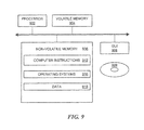
- FIG. 9 is a schematic representation of an exemplary computer that can perform at least a portion of the processing shown in FIGS. 5 and 7 ;
- FIG. 10 is a schematic representation of an exemplary HVAC system coupled to a processing environment in a cloud configuration.
- a ventilation system for a building typically includes one or more air handling units and associated fan systems which, together, perform HVAC functions including: maintaining building pressurization, providing sufficient amounts of fresh air to occupants, controlling moisture levels with the building, controlling airborne dust or particulate levels, and the control of building air temperature.
- exemplary embodiments of the invention are applicable to any ventilation system that can benefit from the application of an airside economizer.
- This generally includes, but is not limited to, multiple pass air handling systems, which are also typically referred to as recirculating air systems.
- FIG. 3 shows an exemplary multiple pass air handling system 300 having economizer control in accordance with exemplary embodiments of the invention.
- the air handling system 300 can form a part of a structure 5 , such as a building.
- the system 300 has a so-called ‘H-type’ fan system topology, which is a well-known type of multiple pass air handling system.
- the system 300 supplies conditioned supply air 314 to spaces or rooms that form zones within the building.
- a given building can have one or more zones and that a single system, such as system 300 , can be applied to multiple zones.
- systems can be dedicated to a large single zone.
- a multiplicity of systems within a building can have multiple zones.
- the supply to fan 311 may comprise any practical number of supply fans that draw from the same mixed air 309 , providing either separate supply air 314 serving different sets of one or more zones.
- the supply fans 311 may be connected in parallel supplying a common set of zones.
- system 300 may include one or more outside air sources 307 , which may be derived from one or more locations and combine with an aggregate of recirculated air 305 to form the mixed air 309 .
- damper assemblies 308 and 306 are controlled by way of damper assemblies 308 and 306 , respectively.
- damper 306 will be closed in a proportionate manner to reduce the recirculated air component 305 .
- recirculated air component 305 is increased, outside air 307 will be proportionately reduced.
- the economizer function when, enabled, the economizer function will be implemented using logic within AHU Controls 316 , or it may be a separate controller known to the art as a Proportional Integral Derivative or PID controller, or this logic may be performed using a Programmable Logic Controller (PLC).
- PLC Programmable Logic Controller
- the system will be in its “mechanical assist” mode, in which the cooling coil 313 will be enabled to provide partial cooling to achieve the desired temperature setpoint.
- Ventiler system that could benefit from an airside economizer that is efficiently enabled and disabled.
- Exemplary ventilation system topologies include, but are not limited to, dual duct supply air systems, recirculating air handling systems with dedicated outside air, and recirculating air handling systems with relief fans.
- the ventilation system 300 includes sensor locations 319 , 320 to determine latent and sensible heat properties of the return air and the outside air, respectively.
- the sensor location 319 pertains to the recirculated air 305 , unless stated otherwise, that airstream is substantially the same as the return air 301 , which allows us to assume the sensor location 319 is monitoring the return air. It is understood that exemplary embodiments of the invention are not limited to monitoring recirculated air 305 as return air 301 , rather, sensor location 319 could be any suitable location within the ventilation system to sample return air 301 , including locations on both the inlet and discharge side of return air fan 302 .
- exemplary embodiments of the invention provide methods and apparatus for determining when conditions are suitable for operating an economizer by establishing comparable measurements using the same units of measurement (one measurement for the return air and one for the outside air) that are indicative of the predicted cooling load placed on the AHU as each air source is separately introduced.
- An exemplary system determines whether moisture removal takes place as return or outside air is introduced to the AHU, and uses this information to determine whether the measurement indicative of cooling load relates only to sensible cooling or a combination of sensible and latent cooling. If moisture removal is predicted, then the comparable measurement will be indicative of both the sensible and latent energy associated with the cooling process. If moisture removal is not predicted, then the comparable measurement will be indicative of only the sensible energy associated, with the cooling process.
- the economizer is enabled when the comparable measurement established for the return air is numerically larger than that established for the outside air.
- determining whether moisture removal takes place as the air source is introduced is accomplished by either measuring or deriving the dewpoint temperature of the air source and comparing it to the measured supply air discharge temperature. Moisture removal is expected to take place if the dewpoint temperature of the air source numerically exceeds the measured supply air temperature.
- sensor locations 319 and 320 can be used to establish dewpoint temperature measurements of the return air stream 305 and outside air 307 , respectively.
- the dewpoint temperature readings can then be individually compared to the dry-bulb temperature of the supply discharge air 314 in order to predict if moisture removal will take place for each air source 305 and 307 .
- this invention is not restricted to the use of de point temperature to predict if a dry- or wet-coil condition will result.
- the measured humidity ratio of each air source 305 and 307 can be compared to the predicted humidity ratio value of the supply air 314 . If the measured humidity ratio of an input air source 305 or 307 exceeds the predicted maximum value for the supply air 314 , then the conditioning of that air source will result in a wet-coil.
- determining whether moisture removal takes place as the air source is introduced is accomplished by either measuring or deriving the dewpoint temperature of the air source and comparing it to the expected supply air discharge temperature.
- the expected supply air discharge temperature is the temperature to which the AHU 316 controls the temperature of supply air 314 . This expected temperature is often referred to in the art as the temperature setpoint.
- the sensor locations 319 and 320 are capable of providing either derived or directly measured characteristics of the airstream sufficient to establish, a measurement that is indicative of the dewpoint temperature of the air source, the dry-bulb temperature of the air source, and a measurement that accounts for the moisture-related or latent energy of the air source.
- each sensor location is capable of producing a measurement or calculation that is processed either locally or remotely that includes: dewpoint temperature, dry-bulb temperature, and enthalpy.
- remote measurements are made, such as by using a multipoint air sampling system, such the exemplary networked air sampling system described in U.S. Pat. No. 6,125,710 and/or the duct probe assembly system described in U.S. Pat. No. 7,421,911, which are herein incorporated by reference.
- a multipoint air sampling system such as the exemplary networked air sampling system described in U.S. Pat. No. 6,125,710 and/or the duct probe assembly system described in U.S. Pat. No. 7,421,911, which are herein incorporated by reference.
- the teachings of U.S. Pat. No. 6,125,710 enable highly accurate dewpoint temperature measurements to be made with minimal tolerance stacking errors between measured locations, which is useful in exemplary embodiments of the invention, given the comparative function that is performed when assessing which air source (return 305 or outside air 307 ) poses the least cooling load on the AHU. Further, the teachings of U.S. Pat. No.
- 7,421,911 are useful for combining the precise remote measurement of dewpoint temperature from the system described in U.S. Pat. No. 6,125,710 and combining it with a local dry-bulb temperature measurement from locations 319 and 320 to produce a highly accurate virtual measurement of enthalpy.
- the sensor locations 319 and 320 incorporate dry-bulb temperature measurements and moisture related measurements which sense physically different locations of the return or outside air sources 305 , 302 , 307 .
- this may be appropriate when it is desirable to minimize the number of sensors involved to produce the economizer changeover function and it is desired to use a return air dry-bulb temperature measurement that is being performed for the purpose of another function within the building.
- FIG. 4 illustrates an exemplary embodiment of a system used to provide the economizer switchover function according to an exemplary embodiment of the invention.
- the sensor locations 319 and 320 utilize duct probes like those described in U.S. Pat. No. 7,421,911 to provide a dry-bulb temperature measurement at the physical locations where the probes 319 and 320 are mounted.
- Moisture measurements are performed by a multipoint air sampling system, such as that described in U.S. Pat. No. 6,125,710.
- air samples are drawn through structured cable 402 , which are sequenced through a node controller 401 , conveyed through a common backbone 403 , which can be identical or similar to structured cable 402 , and sensed via sensor suite 404 .
- An exemplary structured cable 402 and 403 is described in U.S. Pat. No. 7,360,461 B2, which includes tubing that enables air samples to be transported with minimal loss to the properties of interest.
- the property of interest is the moisture concentration within the air sample that should not degrade or change, as it is conveyed from probes 319 or 320 through the structured cable 402 , the node controller 401 , and structured cable 403 , to the sensor suite 404 .
- Structured cable 402 and 403 also provide power, control, and communications wiring to support the interconnection of the elements of this system,
- the central controller can be separate from the sensor suite and that there may be any practical number of sensor suites operated by the central controller, which is the main CPU or computer that operates the multipoint air sampling system and may also be the device which performs the logic to determine what the state of the economizer should be. This logic may produce the economizer changeover signal that will be communicated to the economizer controls,
- a network connection 405 allows the central controller 404 to communicate with the AHU controls 316 , where the AHU controls 316 are responsible for implementing the economizer control function.
- AHU controls 316 are responsible for implementing the economizer control function.
- BACnet Building Automation and Control Networking protocol specified by the American Society of Heating, Refrigeration and Air Conditioning Engineers (ASHRAE).
- the network connection 405 can support BACnet communications over a TCP/IP network between central controller 404 and MILT controls 316 .
- the central controller 404 can communicate to the specific economizer controls using a variety of methods, including other networking schemes and analog signals.
- some AHU types are relatively simple packaged rooftop units (RTUs) that may have separate controls for controlling the economizer function and are capable of interfacing with analog signals or external relays in order to obtain a changeover or lockout signal to enable or disable the economizer.
- RTUs relatively simple packaged rooftop units
- FIG. 5 shows an exemplary sequence of steps 500 for generating an economizer lockout signal in accordance with exemplary embodiments of the invention.
- the processing 500 to generate the lockout signal is performed by the central controller 404 ( FIG. 4 ) as a part of system 400 .
- this arrangement is preferred because the processing described below includes signal conditioning, scaling, and significant programming.
- AHU controls 316 which could form a part of a building automation system (BAS), or other system or device. Further, the processing of FIG. 5 could be implemented using a Programmable Logic Controller (PLC), or other programmable device that is not part of the AHU controls.
- BAS building automation system
- PLC Programmable Logic Controller
- the system determines if the return or outside air sources will be subject to latent cooling (testing for a wet coil condition) by comparing the dewpoint temperature of each air source ( 305 and 307 ) to the supply air temperature.
- the measurements can be made via a duct probe at location 405 through the node controller 401 , or it could be measured through a separate probe 317 through AHU controls 316 .
- the temperature measured by probe 405 or 317 to include what is known in the art as a duct averaging temperature sensor, which provides temperature measurements that are indicative of the average temperature of the air flowing through the duct or plenum cross section. This can be helpful, given the stratification that can take place as the return and outside airstreams mix, resulting in non-uniform temperature across a given cross section of the supply flow stream.
- a wet coil/dry coil test is accomplished for the outside air to source 307 in step 502 .
- the supply air temperature setpoint which may include an assumed value (for example 55 degrees F.) or an actual value that is read from the system that is responsible for controlling the supply air temperature of the AHU providing supply air 314 .
- the AHU controls 316 are responsible for is controlling the supply air temperature
- the current setpoint (which is often a variable) could be conveyed through a network connection 405 , such as via. BACnet. This information can be dynamically inserted into the processing of FIG.
- supply air temperature setpoints are often varied as cooling load conditions within a building vary influencing when it is best to operate the economizer.
- the temperature setpoint in some systems may be increased during evening hours when the cooling load within a building is generally lower.
- the supply air temperature setpoint may be varied seasonally, so that there is a higher temperature setpoint during colder months and a lower temperature setpoint during warmer months.
- the anticipated setpoint that will prevail as the economizer is enabled should be used.
- the system estimates the cooling load presented by each air source to create a comparable measurement indicative of the energy associated with conditioning each that can be used to assess whether or not the economizer should be enabled. If the outcome of the test for a wet coil condition is “yes”, then the approximation of the cooling load associated with the respective air source needs to include both a sensible and latent energy term. Those who are skilled in the art of psychrometrics will recognize that one way to simultaneously account for both sensible and latent energy is by way of an enthalpy measurement. Further, in order to understand both the sensible and latent cooling provided by cooling coil 313 , one can calculate the enthalpy difference between the air source and supply air 314 .
- the supply air enthalpy is approximated by considering that this state is a wet coil condition and, therefore, with that knowledge and the knowledge of the supply air temperature (or, alternatively, the supply air temperature setpoint), the expected supply air enthalpy under this condition (predicted wet coil enthalpy) can be calculated.
- the objective here is to create a comparable measurement that is indicative of the cooling load presented by each air source for both dry-coil and wet-coil conditions.
- One consideration is to be able to handle the case where one air source ( 305 or 307 ) is subject to latent cooling while the other ( 305 or 307 ) is subject to sensible cooling, and to be able to compare the two with the same unit of measurement.
- One convenient unit of measurement germane to this process is energy rate as a function of volumetric flow rate. For example, the energy associated with either sensible cooling or a cooling process involving both sensible and latent cooling can easily be converted to units of BTUs/Hour per CFM.
- Equation 4 the application of Equation 4 to estimate a comparable measurement of cooling rate when there is a wet coil condition is illustrated as logic steps 504 and 506 .
- logic steps 503 and 505 utilize Equation 5. More particularly, step 503 is the return air dry coil determination (no path) from step 501 and step 504 is the return air wet coil determination (yes path) from step 501 . Similarly, step 505 is the outside air dry coil determination from step 502 and step 506 is the outside air wet coil determination from step 502 .
- the outside air and return air cooling rate values are compared in step 507 to determine if the outside air cooling rate estimate is less than that of the return air. If not, then the economizer will be locked out or disabled in step 510 . If, on the other hand, the estimated cooling rate for the outside air is less than that of the return air, it may be economical to enable the economizer, barring other potential lockout conditions as determined in step 508 .
- Exemplary lockout conditions for step 508 include a provision for freeze protection and other conditions well known to one of ordinary skill in the art. It is understood that in colder climates there can be conditions where the outside air is simply too cold to operate an economizer. This is due to the limitations of the effectiveness with which the return air and outside air are mixed, giving rise to stratified layers of unmixed air that can enter the AHU. When it is very cold outside, particularly when it's below freezing temperatures, these stratified layers of air can damage the cooling cool 313 . Therefore, to avoid this, the economizer can be locked out when it is below freezing temperatures outside.
- step 509 the economizer is enabled.
- any practical signal well known to one of ordinary skill in the art can be used to enable or disable the economizer.
- Exemplary signal communication includes, but is not limited to, a command sent through BACnet over communication link 405 to the AHU controls, which contain the economizer function.
- a similar command can be sent over a network (such as 405 ) connecting directly or indirectly to the system that performs the economizer function.
- an enabling signal can be relay contact or other signal which connects to an input on the control, device for economizer control.
- Exemplary embodiments of the invention provide significant advantages over prior art differential enthalpy economizers, particularly during certain dry-coil conditions where the enthalpy difference between return air and outside air is not representative of which air source presents the greatest cooling load, as illustrated in FIG. 6 .
- thy coil outside air condition 601 80 degrees F. dry-bulb and 50 degrees F.
- a differential enthalpy measurement incorrectly disables the economizer for any combination of drier and warmer return air conditions signified by region 602 , which is bounded by dry-bulb temperature line 608 (the dry-bulb temperature of outside air 601 ) and enthalpy line 606 (the enthalpy of outside air 601 which, in this case is 27.6 BTUs/lb).
- Region 603 illustrates, for the outside air condition 601 , the cooler and moister return air conditions where the economizer would be incorrectly enabled using the prior art differential enthalpy approach.
- Region 603 is bounded by outside air dry-bulb temperature 608 , outside air enthalpy 606 , and enthalpy line 607 .
- Enthalpy line 607 is the enthalpy at which the return air cooling load under wet-coil conditions (which may be calculated using equation 4) is equal to the cooling load presented by outside air 601 (which in this case may be calculated using equation 5).
- region 603 includes dewpoint temperatures above the supply maximum dewpoint, where a wet-coil condition would result, yet, the outside air condition 601 is not one that would result in a wet-coil condition.
- the differential enthalpy approach can result in erroneous economizer hours.
- Sikh errors are addressed in exemplary embodiments of the invention which properly estimate the cooling load presented by the outside air and return air, regardless of the state of each air source.
- regions 602 and 603 of FIG. 6 can be dynamically compensated for, at various values of outside air condition 601 , using a differential enthalpy approach based on an estimated lockout enthalpy value for return air wet-coil conditions and a differential dry-bulb approach based on an estimated lockout dry-bulb temperature value for return air dry coil conditions, as shown in FIG. 7 .
- processing 700 is such that when the return air source 305 results in a wet-coil condition, the system performs an enthalpy comparison between the return air 305 enthalpy and enthalpy line 607 (a calculated effective enthalpy lockout value based on outside air cooling load) in order to establish if the economizer should be enabled.
- the return air 305 results in a dry coil condition, the return air 305 is compared to an estimated effective dry-bulb lockout value based on outside air 307 cooling load.
- step 701 the system determines if the outside air 307 will result in a wet-coil or a dry-coil condition. This is again based on whether the outside air dewpoint temperature exceeds the supply air 317 dry-bulb temperature, or in an alternate embodiment, the supply air 314 temperature setpoint. If the outside air 307 results in a wet-coil condition, then in step 702 the enthalpy lockout value (enthalpy line 607 ) is set equal to the outside air 307 enthalpy.
- the lockout dry-bulb temperature is calculated based on Equation 6 below, which determines the return air ( 305 ) dry-bulb temperature at which the return air cooling load is equivalent to the cooling load presented by the outside air ( 307 ).
- Lockout Drybulb Temperature 4.17 (Outside Air Enthalpy ⁇ Apply Air Enthalpy+Supply Air Drybulb Temperature (Eq. 6)
- the return air dry-coil dry-bulb lockout value is equivalent to the outside air thy-bulb temperature.
- the enthalpy lockout value (enthalpy line 607 ) is calculated based on the following equation (Equation 7), as shown in step 703 , which determines the wet-coil return air ( 305 ) enthalpy value at which the return air cooling load is equal to the cooling load presented by the outside air.
- Enthalpy Lockout Value 0.24(Outside Air Drybulb Temperature ⁇ Supply air Drybulb Temperature+Supply Air Enthalpy (Eq. 7)
- step 704 the system determines whether the return air 305 will produce a wet-coil or dry-coil condition. This is again based on whether the return air dewpoint temperature exceeds the supply air 317 dry-bulb temperature, or, as an alternate embodiment, the supply air 314 temperature setpoint.
- step 704 establishes that the return air 305 will produce a wet-coil condition then in step 705 the system determines if the return air enthalpy exceeds enthalpy line 607 (the enthalpy lockout value). If not, then the return air cooling load is less than that of the outside air 307 , and the economizer will be locked out via step 709 . If the return air enthalpy does exceed enthalpy line 607 , then the return air cooling load will be greater than that of the outside air 307 , and the economizer will be enabled in step 707 , assuming other lockout conditions do not exist as determined in step 706 .
- enthalpy line 607 the enthalpy lockout value
- step 708 the system compares the return air 305 dry-bulb temperature to the lockout dry-bulb temperature established by step 702 or 703 , if not, then the cooling load presented by the return air 305 is less than that presented by the outside air 307 , and the economizer will be locked out in step 709 . If the return air dry-bulb temperature does exceed the lockout dry-bulb temperature, then the cooling load presented by the return air 305 is greater than that presented by the outside air 307 , and the economizer will be enabled in step 707 , assuming other lockout conditions do not apply, as evaluated in step 706 .
- FIG. 8 further illustrates the functionality of FIG. 7 .
- the outside air 307 would result in a wet coil condition, given that its dewpoint temperature exceeds the maximum supply air dewpoint temperature (the supply air temperature).
- the outside air state is depicted by 801 which, for this example, is at 70 degrees Fahrenheit (dry-bulb temperature) and 58 degrees Fahrenheit (dewpoint temperature). This corresponds with an enthalpy value of about 28 BTUs/pound of dry air, and this enthalpy line is drawn as 805 . From processing 700 , because in this case the outside air source 307 will result in a wet-coil condition, the enthalpy line 607 will be equal to enthalpy line 805 .
- the economizer will be enabled when the return air source 305 enthalpy exceeds that of the outside air; again, depicted by enthalpy line 805 which, in this example is the enthalpy lockout value.
- the lockout dry-bulb temperature (calculated within 702 and equation 6) is approximately 75 degrees Fahrenheit, depicted as 806 . This means that for return air conditions that result in a dry coil., according to processing 700 , the economizer will be enabled when the return air source 305 dry-bulb temperature exceeds 75 degrees Fahrenheit.
- region 802 which is bounded by enthalpy line 805 and dry-bulb temperature line 806 .
- Region 802 represents the range of return air 305 conditions which are drier and warmer than the stated outside air condition 801 for which the prior-art differential enthalpy changeover logic will produce erroneous results.
- the prior-art differential enthalpy changeover logic would incorrectly disable the economizer because any return air enthalpy value falling within region 802 is less than that of outside air 801 signified by 805 .
- Not enabling the economizer when the return air conditions fall within region 802 results in a waste of energy because it requires more cooling energy to condition the return air 305 under any of these conditions than it does to condition outside air 801 to achieve supply air condition 804 .
- the dry-bulb and enthalpy lockout values that are calculated from equations 6 and 7 as a part of processing 700 illustrate the adaptive nature of exemplary embodiments of the invention, as these parameters are highly variable with outside air and supply air conditions. This illustrates the deficiencies of the prior-art differential dry-bulb and differential enthalpy changeover approaches, which do not compensate for dry or wet coil conditions or account for the conditions where the return air results in a wet coil conditions while the outside air results in a dry-coil condition, and vice versa.
- Prior-art solid state enthalpy controllers such as that described within U.S. Pat. No. 3,949,607 attempt to provide a hybrid lockout curve (sometimes called a combination high-limit) that approaches a fixed enthalpy line at certain high relative humidity conditions and a fixed dry-bulb temperature line at low relative humidity conditions, but does not take the dynamic supply air conditions into account.
- the '607 patent also does not properly account for the return air conditions, particularly as it relates to dry and wet coil operation.
- prior art solid state enthalpy controllers do not adaptively adjust the enthalpy dry-bulb lockout curve as outside air and supply air conditions vary which, aside from sensor accuracy issues, can result in substantial energy waste.
- exemplary embodiments of the invention provide a variable combination high-limit curve that, in one embodiment, will vary with outside air conditions and wet or dry coil conditions or, conversely, adapted to provide a variable combination high-limit curve that will vary with return air conditions and wet or dry coil conditions.
- the exemplary processing 700 of FIG. 7 is one of many possible methods that can be used to create a highly accurate economizer changeover signal.
- Other alternative embodiments will become apparent to one of ordinary skill in the art without departing from the scope of the present invention.
- step 701 the system checks to see if the return air source 305 results in a wet or dry coil condition and, processing in steps 702 and 703 establishes the enthalpy and dry-bulb lockout values that the outside air can be compared against in order to establish whether or not to enable or disable the economizer.
- a computer includes a processor 902 , a volatile memory 904 , a non-volatile memory 906 , and a graphical user interface (GUI) 908 (e.g., a mouse, a keyboard, a display, for example).
- the non-volatile memory 906 stores computer instructions 912 , an operating system 916 and data 918 .
- the computer instructions 912 are executed by the processor 902 out of volatile memory 904 to perform all or part of the processing, such as processing 500 and 700 .
- a disk 909 comprises a machine-readable medium that stores executable instructions to implement processing, such as processing 500 and 700 . It is understood that processing 500 and 700 are exemplary processing embodiments and that other embodiments comprising other processing at least partly performed by the computer are within the scope of the invention.
- the computer of FIG. 9 is a part of the sensor suite and central controller 404 .
- Processing 500 and 700 are not limited to use with the hardware and software of FIG. 9 ; they may find applicability in any computing or processing environment and with any type of machine or set of machines that is capable of running a computer program. Processing 500 and 700 and/or other processing may be implemented in hardware, software, or a combination of the two. Processes 500 and 700 may be implemented in computer programs executed on programmable computers/machines that each includes a processor, a storage medium or other article of manufacture that is readable by the processor (including volatile and non-volatile memory and/or storage elements), at least one input device, and one or more output devices. Program code may be applied to data entered using an input device to perform process 500 and/or process 700 and to generate output information.
- the system may be implemented, at least in part, via a computer program product, (e.g., in a machine-readable storage device), for execution by, or to control the operation of, data processing apparatus (e.g., a programmable processor, a computer, or multiple computers)).
- data processing apparatus e.g., a programmable processor, a computer, or multiple computers
- Each such program may be implemented in a high level procedural or object-oriented programming language to communicate with a computer system.
- the programs may be implemented in assembly or machine language.
- the language may be a compiled or an interpreted language and it may be deployed in any form, including as a stand-alone program or as a module, component, subroutine, or other unit suitable for use in a computing environment.
- a computer program may be deployed to be executed on one computer or on multiple computers at one site or distributed across multiple sites and interconnected by a communication network.
- a computer program may be stored on a storage medium or device (e.g., CD-ROM, hard disk, or magnetic diskette) that is readable by a general or special purpose programmable computer for configuring and operating the computer when the storage medium or device is read by the computer to perform processes 500 and 700 .
- Processes 500 and 700 may also be implemented as a machine-readable storage medium, configured with a computer program, where upon execution, instructions in the computer program cause the computer to operate in accordance with processes 500 and 700 .
- FIGS. 5 and 7 associated with implementing the system may be performed by one or more programmable processors executing one or more computer programs to perform the functions of the system. All or part of the system may be implemented as, special purpose logic circuitry (e.g., FPGA (field programmable gate array) and/or ASIC (application-specific integrated circuit)).
- FPGA field programmable gate array
- ASIC application-specific integrated circuit
- an HVAC system 1000 is coupled to a remote processing environment 1002 via a network 1004 , in a so-called cloud configuration.
- the processing environment 1002 performs the processing, such as processing 500 and 700 , to generate control signals for controlling an economizer.
- the processing environment 1002 includes an article, such as a non-volatile memory, containing stored instructions that enable a machine, such as HVAC system 1000 , to control an economizer in accordance with exemplary embodiments of the invention. It is understood that an article containing non-transitory stored instructions can comprise any memory that can form a part of a system, as well as a disk.
Abstract
Description
h(BTU/lb)=0.240T sa +W lb(1061+0.444T sa) (Eq. 1)
where, h=enthalpy in BTU/lb, Tsa=Supply Discharge Temp (deg F.), and Wlb=humidity ratio in units of pounds water per pound of dry air. The humidity ratio can be calculated as follows:
where, Pwsd=saturation vapor pressure at the dew point temperature in psia. Pwsd can be evaluated using Equation (3) for Pbar=barometric pressure in psia. (assume 14.64 psia)
P wsd =e C
where, T=supply dewpoint Temp in ° R=T sa_sat temp (deg F.)±459.67,
Cooling Rate=4.5(Δh) BTU's per hour per CFM (Eq 4)
where, Δh=air source enthalpy minus anticipated supply air enthalpy.
Cooling Rate=1.08 (ΔT) BTU's per hour per CFM (Eq 5)
where, ΔT=air source dry-bulb temperature minus anticipated supply air dry-bulb temperature.
Lockout Drybulb Temperature=4.17 (Outside Air Enthalpy−Apply Air Enthalpy+Supply Air Drybulb Temperature (Eq. 6)
Enthalpy Lockout Value=0.24(Outside Air Drybulb Temperature−Supply air Drybulb Temperature+Supply Air Enthalpy (Eq. 7)
Claims (10)
Priority Applications (1)
| Application Number | Priority Date | Filing Date | Title |
|---|---|---|---|
| US14/246,308 US8930029B2 (en) | 2011-07-08 | 2014-04-07 | Methods and apparatus for differential energy based airside economizer changeover |
Applications Claiming Priority (2)
| Application Number | Priority Date | Filing Date | Title |
|---|---|---|---|
| US13/178,600 US8725300B2 (en) | 2011-07-08 | 2011-07-08 | Methods and apparatus for differential energy based airside economizer changeover |
| US14/246,308 US8930029B2 (en) | 2011-07-08 | 2014-04-07 | Methods and apparatus for differential energy based airside economizer changeover |
Related Parent Applications (1)
| Application Number | Title | Priority Date | Filing Date |
|---|---|---|---|
| US13/178,600 Division US8725300B2 (en) | 2011-07-08 | 2011-07-08 | Methods and apparatus for differential energy based airside economizer changeover |
Publications (2)
| Publication Number | Publication Date |
|---|---|
| US20140216707A1 US20140216707A1 (en) | 2014-08-07 |
| US8930029B2 true US8930029B2 (en) | 2015-01-06 |
Family
ID=46149015
Family Applications (2)
| Application Number | Title | Priority Date | Filing Date |
|---|---|---|---|
| US13/178,600 Active 2032-07-08 US8725300B2 (en) | 2011-07-08 | 2011-07-08 | Methods and apparatus for differential energy based airside economizer changeover |
| US14/246,308 Active US8930029B2 (en) | 2011-07-08 | 2014-04-07 | Methods and apparatus for differential energy based airside economizer changeover |
Family Applications Before (1)
| Application Number | Title | Priority Date | Filing Date |
|---|---|---|---|
| US13/178,600 Active 2032-07-08 US8725300B2 (en) | 2011-07-08 | 2011-07-08 | Methods and apparatus for differential energy based airside economizer changeover |
Country Status (4)
| Country | Link |
|---|---|
| US (2) | US8725300B2 (en) |
| EP (1) | EP2729737B1 (en) |
| CA (1) | CA2836461C (en) |
| WO (1) | WO2013009390A1 (en) |
Cited By (2)
| Publication number | Priority date | Publication date | Assignee | Title |
|---|---|---|---|---|
| US11243004B1 (en) * | 2015-05-26 | 2022-02-08 | Alarm.Com Incorporated | Enthalpy measurement and system control |
| US11300302B2 (en) * | 2016-10-24 | 2022-04-12 | Mitsubishi Electric Corporation | Air conditioner system, air conditioner control device, air conditioner method, and program for control using water circulation and based on indoor latent and sensible heat loads |
Families Citing this family (18)
| Publication number | Priority date | Publication date | Assignee | Title |
|---|---|---|---|---|
| JP5759808B2 (en) * | 2011-06-30 | 2015-08-05 | 株式会社東芝 | Air conditioning system and air conditioning control method for server room management |
| US9435557B2 (en) | 2013-01-24 | 2016-09-06 | Belimo Holding Ag | Control unit for an HVAC system comprising an economizer and method for operating such control unit |
| US9416987B2 (en) | 2013-07-26 | 2016-08-16 | Honeywell International Inc. | HVAC controller having economy and comfort operating modes |
| US9581350B2 (en) * | 2013-10-29 | 2017-02-28 | Lennox Industries Inc. | Mixed air temperature sensor bypass |
| US10119711B2 (en) | 2013-12-17 | 2018-11-06 | Optimum Energy Llc | Air handler unit including a smart valve |
| US10060642B2 (en) | 2014-10-22 | 2018-08-28 | Honeywell International Inc. | Damper fault detection |
| WO2016150663A1 (en) * | 2015-03-24 | 2016-09-29 | Danfoss A/S | A method for controlling an air handling unit |
| US10816229B2 (en) * | 2015-06-24 | 2020-10-27 | Termotera Ltd | Harvesting energy from humidity fluctuations |
| CN106468471A (en) * | 2016-11-24 | 2017-03-01 | 安徽皖拓自动化有限公司 | A kind of Air-conditioning system |
| RU176378U1 (en) * | 2017-02-09 | 2018-01-17 | Волкаст Лимитед | Air handling unit |
| US11326795B2 (en) * | 2017-04-21 | 2022-05-10 | Smac Technologies Pty Ltd | Air conditioning system with reduced mould growth conditions |
| CN107367939A (en) * | 2017-08-22 | 2017-11-21 | 东华大学 | The control method being combined based on combined integral controller with dual control system |
| US10948214B2 (en) * | 2018-05-07 | 2021-03-16 | Johnson Controls Technology Company | HVAC system with economizer switchover control |
| CN109058132B (en) * | 2018-07-12 | 2020-10-16 | 芜湖拓达电子科技有限公司 | Diesel generator air inlet processing apparatus |
| US11181409B2 (en) | 2018-08-09 | 2021-11-23 | General Electric Company | Monitoring and control system for a flow duct |
| US11460202B2 (en) | 2019-04-30 | 2022-10-04 | Gary Gerard Powers | Roof mounted ventilation assembly |
| CN114265442B (en) * | 2021-11-19 | 2023-02-24 | 青岛海尔空调电子有限公司 | Method for determining outdoor wet bulb temperature, fan control method and electronic equipment |
| US20240003568A1 (en) * | 2022-06-30 | 2024-01-04 | Schneider Electric Industries Sas | Systems and methods for optimizing control of an air handling unit (ahu) to minimize electrical and thermal energy consumption of the ahu |
Citations (16)
| Publication number | Priority date | Publication date | Assignee | Title |
|---|---|---|---|---|
| US3949607A (en) * | 1974-10-03 | 1976-04-13 | Honeywell Inc. | Enthalpy control apparatus for air conditioning |
| US3979922A (en) * | 1974-12-30 | 1976-09-14 | Honeywell Inc. | Energy conservation air conditioning system |
| US4182180A (en) * | 1977-05-26 | 1980-01-08 | Honeywell Inc. | Enthalpy comparator |
| US4186564A (en) * | 1977-09-23 | 1980-02-05 | Melvin Myers | Air ventilation system |
| US4312226A (en) | 1979-11-30 | 1982-01-26 | Mark Controls Corporation | Comparator |
| US4362026A (en) * | 1980-10-27 | 1982-12-07 | Miller Lloyd W | Enthalpy control |
| US4457357A (en) * | 1982-01-12 | 1984-07-03 | Arnhem Peter D Van | Air-conditioning apparatus |
| US5276630A (en) * | 1990-07-23 | 1994-01-04 | American Standard Inc. | Self configuring controller |
| US5791408A (en) | 1996-02-12 | 1998-08-11 | Johnson Service Company | Air handling unit including control system that prevents outside air from entering the unit through an exhaust air damper |
| US6125710A (en) * | 1997-04-15 | 2000-10-03 | Phoenix Controls Corporation | Networked air measurement system |
| US7421911B2 (en) * | 2005-12-20 | 2008-09-09 | Desrochers Eric M | Duct probe assembly system for multipoint air sampling |
| US7434413B2 (en) * | 2005-01-10 | 2008-10-14 | Honeywell International Inc. | Indoor air quality and economizer control methods and controllers |
| US20090210096A1 (en) * | 2008-02-19 | 2009-08-20 | Liebert Corporation | Climate control system for data centers |
| US20100083682A1 (en) * | 2008-10-03 | 2010-04-08 | Koehler Michael J | Air Conditioning Unit with Economizer and Filter Assembly |
| US20100126208A1 (en) * | 2008-11-12 | 2010-05-27 | Scott Dean Stammer | AC Unit with Economizer and Sliding Damper Assembly |
| US7890215B2 (en) * | 2006-12-22 | 2011-02-15 | Duncan Scot M | Optimized control system for cooling systems |
Family Cites Families (2)
| Publication number | Priority date | Publication date | Assignee | Title |
|---|---|---|---|---|
| US6241950B1 (en) | 1998-02-13 | 2001-06-05 | Airxpert Systems, Inc. | Fluid sampling system |
| US7360461B2 (en) | 2004-09-23 | 2008-04-22 | Aircuity, Inc. | Air monitoring system having tubing with an electrically conductive inner surface for transporting air samples |
-
2011
- 2011-07-08 US US13/178,600 patent/US8725300B2/en active Active
-
2012
- 2012-05-17 CA CA2836461A patent/CA2836461C/en active Active
- 2012-05-17 EP EP12723351.8A patent/EP2729737B1/en active Active
- 2012-05-17 WO PCT/US2012/038322 patent/WO2013009390A1/en active Application Filing
-
2014
- 2014-04-07 US US14/246,308 patent/US8930029B2/en active Active
Patent Citations (16)
| Publication number | Priority date | Publication date | Assignee | Title |
|---|---|---|---|---|
| US3949607A (en) * | 1974-10-03 | 1976-04-13 | Honeywell Inc. | Enthalpy control apparatus for air conditioning |
| US3979922A (en) * | 1974-12-30 | 1976-09-14 | Honeywell Inc. | Energy conservation air conditioning system |
| US4182180A (en) * | 1977-05-26 | 1980-01-08 | Honeywell Inc. | Enthalpy comparator |
| US4186564A (en) * | 1977-09-23 | 1980-02-05 | Melvin Myers | Air ventilation system |
| US4312226A (en) | 1979-11-30 | 1982-01-26 | Mark Controls Corporation | Comparator |
| US4362026A (en) * | 1980-10-27 | 1982-12-07 | Miller Lloyd W | Enthalpy control |
| US4457357A (en) * | 1982-01-12 | 1984-07-03 | Arnhem Peter D Van | Air-conditioning apparatus |
| US5276630A (en) * | 1990-07-23 | 1994-01-04 | American Standard Inc. | Self configuring controller |
| US5791408A (en) | 1996-02-12 | 1998-08-11 | Johnson Service Company | Air handling unit including control system that prevents outside air from entering the unit through an exhaust air damper |
| US6125710A (en) * | 1997-04-15 | 2000-10-03 | Phoenix Controls Corporation | Networked air measurement system |
| US7434413B2 (en) * | 2005-01-10 | 2008-10-14 | Honeywell International Inc. | Indoor air quality and economizer control methods and controllers |
| US7421911B2 (en) * | 2005-12-20 | 2008-09-09 | Desrochers Eric M | Duct probe assembly system for multipoint air sampling |
| US7890215B2 (en) * | 2006-12-22 | 2011-02-15 | Duncan Scot M | Optimized control system for cooling systems |
| US20090210096A1 (en) * | 2008-02-19 | 2009-08-20 | Liebert Corporation | Climate control system for data centers |
| US20100083682A1 (en) * | 2008-10-03 | 2010-04-08 | Koehler Michael J | Air Conditioning Unit with Economizer and Filter Assembly |
| US20100126208A1 (en) * | 2008-11-12 | 2010-05-27 | Scott Dean Stammer | AC Unit with Economizer and Sliding Damper Assembly |
Non-Patent Citations (6)
| Title |
|---|
| European Application No. 12723351.8 Response to Office Action dated Aug. 29, 2014, 43 pages. |
| Notification Concerning Transmittal of International Preliminary Report on Patentability (Chapter I of the Patent Cooperation Treaty), PCT/US2012/038322, date of mailing Jan. 23, 2014, 8 pages. |
| PCT Search Report and Written Opinion of the ISA; mailed Jul. 20, 2012; for PCT Pat. App. No. PCT/US2012/038322; 10 pages. |
| Steven T. Taylor, P.E., C. Hwakong Cheng, "Economizer High Limit Controls and Why Enthalpy Economizers Don't Work", Nov. 2010, ASHRAE Journal, pp. 1-11. |
| U.S. Appl. No. 13/178,600, filed Jul. 8, 2011, Desrochers. |
| U.S. Appl. No. 13/178,600, filed Jul. 8, 2011, IFW downloaded May 22, 2014, 168 pages. |
Cited By (2)
| Publication number | Priority date | Publication date | Assignee | Title |
|---|---|---|---|---|
| US11243004B1 (en) * | 2015-05-26 | 2022-02-08 | Alarm.Com Incorporated | Enthalpy measurement and system control |
| US11300302B2 (en) * | 2016-10-24 | 2022-04-12 | Mitsubishi Electric Corporation | Air conditioner system, air conditioner control device, air conditioner method, and program for control using water circulation and based on indoor latent and sensible heat loads |
Also Published As
| Publication number | Publication date |
|---|---|
| US20130013117A1 (en) | 2013-01-10 |
| CA2836461C (en) | 2016-03-29 |
| US20140216707A1 (en) | 2014-08-07 |
| EP2729737A1 (en) | 2014-05-14 |
| WO2013009390A1 (en) | 2013-01-17 |
| CA2836461A1 (en) | 2013-01-17 |
| US8725300B2 (en) | 2014-05-13 |
| EP2729737B1 (en) | 2018-10-24 |
Similar Documents
| Publication | Publication Date | Title |
|---|---|---|
| US8930029B2 (en) | Methods and apparatus for differential energy based airside economizer changeover | |
| JP5848578B2 (en) | Outside air cooling system and data center | |
| US11262092B2 (en) | Air conditioning system including a ventilator that supplies humidified outdoor air | |
| JP5185319B2 (en) | Air conditioning system and air conditioning control method for server room management | |
| US9185829B2 (en) | Air-conditioning system and air-conditioning method for server room management | |
| JP3310118B2 (en) | Humidification method and air conditioning system | |
| JP5759808B2 (en) | Air conditioning system and air conditioning control method for server room management | |
| US20110146651A1 (en) | Altitude Adjustment for Heating, Ventilating and Air Conditioning Systems | |
| US20150060557A1 (en) | Energy saving apparatus, system and method | |
| US9091454B2 (en) | Air change rate measurement and control | |
| Zhang et al. | A museum storeroom air-conditioning system employing the temperature and humidity independent control device in the cooling coil | |
| US10948214B2 (en) | HVAC system with economizer switchover control | |
| US20220090813A1 (en) | Outside air treatment device and air conditioning system | |
| Dhillon et al. | Comparison of steady-state and dynamic load-based performance evaluation methodologies for a residential air conditioner | |
| CN108105965A (en) | A kind of air-conditioning system and its control method for controlling air-out humidity | |
| CN112902393B (en) | Energy-saving control method and system for air conditioner heat balance laboratory | |
| JP7002918B2 (en) | Ventilation system, air conditioning system, ventilation method and program | |
| Shoukas et al. | Performance Assessment of High Efficiency Variable Speed Air-Source Heat Pump in Cold Climate Applications | |
| CN109237700A (en) | A kind of online change temperature control method of water of air conditioner refrigerating device | |
| JP2003148782A (en) | Outside air cooling system | |
| JP2006064258A (en) | Air conditioning system, air conditioning control device, and air conditioning control method | |
| Dhillon et al. | Comparisons of load-based and AHRI 210/240 testing and rating for residential heat pumps | |
| Proctor et al. | Two-stage high efficiency air conditioners: Laboratory ratings vs. residential installation performance | |
| CN109522662B (en) | Method for calculating mixed air temperature of roof type air conditioner | |
| Kone | SPASPACE HUMIDITY CONTROL THROUGH A SINGLE SPEED VERSUS A VARIABLE SPEED HVAC SOLUTION |
Legal Events
| Date | Code | Title | Description |
|---|---|---|---|
| AS | Assignment |
Owner name: AIRCUITY, INC., MASSACHUSETTS Free format text: ASSIGNMENT OF ASSIGNORS INTEREST;ASSIGNOR:DESROCHERS, ERIC;REEL/FRAME:032621/0968 Effective date: 20110707 |
|
| STCF | Information on status: patent grant |
Free format text: PATENTED CASE |
|
| AS | Assignment |
Owner name: PRIDES CROSSING CAPITAL FUNDING, L.P., MASSACHUSET Free format text: SECURITY INTEREST;ASSIGNOR:AIRCUITY, INC;REEL/FRAME:038179/0616 Effective date: 20160331 |
|
| AS | Assignment |
Owner name: PACIFIC WESTERN BANK, NORTH CAROLINA Free format text: SECURITY INTEREST;ASSIGNOR:AIRCUITY, INC.;REEL/FRAME:044384/0659 Effective date: 20160629 |
|
| MAFP | Maintenance fee payment |
Free format text: PAYMENT OF MAINTENANCE FEE, 4TH YR, SMALL ENTITY (ORIGINAL EVENT CODE: M2551) Year of fee payment: 4 |
|
| AS | Assignment |
Owner name: AIRCUITY, INC., MASSACHUSETTS Free format text: RELEASE BY SECURED PARTY;ASSIGNOR:PACIFIC WESTERN BANK;REEL/FRAME:047009/0660 Effective date: 20180928 |
|
| MAFP | Maintenance fee payment |
Free format text: PAYMENT OF MAINTENANCE FEE, 8TH YR, SMALL ENTITY (ORIGINAL EVENT CODE: M2552); ENTITY STATUS OF PATENT OWNER: SMALL ENTITY Year of fee payment: 8 |
|
| AS | Assignment |
Owner name: PRIDES CROSSING CAPITAL III, L.P, MASSACHUSETTS Free format text: SECURITY INTEREST;ASSIGNOR:AIRCUITY, INC.;REEL/FRAME:063825/0374 Effective date: 20230523 |