US8930116B2 - On-board real-time speed control setpoint variation using stochastic optimization - Google Patents
On-board real-time speed control setpoint variation using stochastic optimization Download PDFInfo
- Publication number
- US8930116B2 US8930116B2 US13/777,049 US201313777049A US8930116B2 US 8930116 B2 US8930116 B2 US 8930116B2 US 201313777049 A US201313777049 A US 201313777049A US 8930116 B2 US8930116 B2 US 8930116B2
- Authority
- US
- United States
- Prior art keywords
- vehicle
- speed
- transition probability
- control policy
- control
- Prior art date
- Legal status (The legal status is an assumption and is not a legal conclusion. Google has not performed a legal analysis and makes no representation as to the accuracy of the status listed.)
- Active, expires
Links
Images


Classifications
-
- B—PERFORMING OPERATIONS; TRANSPORTING
- B60—VEHICLES IN GENERAL
- B60K—ARRANGEMENT OR MOUNTING OF PROPULSION UNITS OR OF TRANSMISSIONS IN VEHICLES; ARRANGEMENT OR MOUNTING OF PLURAL DIVERSE PRIME-MOVERS IN VEHICLES; AUXILIARY DRIVES FOR VEHICLES; INSTRUMENTATION OR DASHBOARDS FOR VEHICLES; ARRANGEMENTS IN CONNECTION WITH COOLING, AIR INTAKE, GAS EXHAUST OR FUEL SUPPLY OF PROPULSION UNITS IN VEHICLES
- B60K31/00—Vehicle fittings, acting on a single sub-unit only, for automatically controlling vehicle speed, i.e. preventing speed from exceeding an arbitrarily established velocity or maintaining speed at a particular velocity, as selected by the vehicle operator
-
- B—PERFORMING OPERATIONS; TRANSPORTING
- B60—VEHICLES IN GENERAL
- B60W—CONJOINT CONTROL OF VEHICLE SUB-UNITS OF DIFFERENT TYPE OR DIFFERENT FUNCTION; CONTROL SYSTEMS SPECIALLY ADAPTED FOR HYBRID VEHICLES; ROAD VEHICLE DRIVE CONTROL SYSTEMS FOR PURPOSES NOT RELATED TO THE CONTROL OF A PARTICULAR SUB-UNIT
- B60W30/00—Purposes of road vehicle drive control systems not related to the control of a particular sub-unit, e.g. of systems using conjoint control of vehicle sub-units, or advanced driver assistance systems for ensuring comfort, stability and safety or drive control systems for propelling or retarding the vehicle
- B60W30/14—Adaptive cruise control
- B60W30/143—Speed control
-
- B—PERFORMING OPERATIONS; TRANSPORTING
- B60—VEHICLES IN GENERAL
- B60W—CONJOINT CONTROL OF VEHICLE SUB-UNITS OF DIFFERENT TYPE OR DIFFERENT FUNCTION; CONTROL SYSTEMS SPECIALLY ADAPTED FOR HYBRID VEHICLES; ROAD VEHICLE DRIVE CONTROL SYSTEMS FOR PURPOSES NOT RELATED TO THE CONTROL OF A PARTICULAR SUB-UNIT
- B60W50/00—Details of control systems for road vehicle drive control not related to the control of a particular sub-unit, e.g. process diagnostic or vehicle driver interfaces
- B60W50/0097—Predicting future conditions
-
- B—PERFORMING OPERATIONS; TRANSPORTING
- B60—VEHICLES IN GENERAL
- B60K—ARRANGEMENT OR MOUNTING OF PROPULSION UNITS OR OF TRANSMISSIONS IN VEHICLES; ARRANGEMENT OR MOUNTING OF PLURAL DIVERSE PRIME-MOVERS IN VEHICLES; AUXILIARY DRIVES FOR VEHICLES; INSTRUMENTATION OR DASHBOARDS FOR VEHICLES; ARRANGEMENTS IN CONNECTION WITH COOLING, AIR INTAKE, GAS EXHAUST OR FUEL SUPPLY OF PROPULSION UNITS IN VEHICLES
- B60K2310/00—Arrangements, adaptations or methods for cruise controls
- B60K2310/24—Speed setting methods
- B60K2310/244—Speed setting methods changing target speed or setting a new target speed, e.g. changing algorithms
-
- B—PERFORMING OPERATIONS; TRANSPORTING
- B60—VEHICLES IN GENERAL
- B60W—CONJOINT CONTROL OF VEHICLE SUB-UNITS OF DIFFERENT TYPE OR DIFFERENT FUNCTION; CONTROL SYSTEMS SPECIALLY ADAPTED FOR HYBRID VEHICLES; ROAD VEHICLE DRIVE CONTROL SYSTEMS FOR PURPOSES NOT RELATED TO THE CONTROL OF A PARTICULAR SUB-UNIT
- B60W50/00—Details of control systems for road vehicle drive control not related to the control of a particular sub-unit, e.g. process diagnostic or vehicle driver interfaces
- B60W2050/0062—Adapting control system settings
- B60W2050/0075—Automatic parameter input, automatic initialising or calibrating means
- B60W2050/0083—Setting, resetting, calibration
-
- B60W2550/142—
-
- B60W2550/20—
-
- B60W2550/402—
-
- B—PERFORMING OPERATIONS; TRANSPORTING
- B60—VEHICLES IN GENERAL
- B60W—CONJOINT CONTROL OF VEHICLE SUB-UNITS OF DIFFERENT TYPE OR DIFFERENT FUNCTION; CONTROL SYSTEMS SPECIALLY ADAPTED FOR HYBRID VEHICLES; ROAD VEHICLE DRIVE CONTROL SYSTEMS FOR PURPOSES NOT RELATED TO THE CONTROL OF A PARTICULAR SUB-UNIT
- B60W2552/00—Input parameters relating to infrastructure
- B60W2552/15—Road slope
-
- B—PERFORMING OPERATIONS; TRANSPORTING
- B60—VEHICLES IN GENERAL
- B60W—CONJOINT CONTROL OF VEHICLE SUB-UNITS OF DIFFERENT TYPE OR DIFFERENT FUNCTION; CONTROL SYSTEMS SPECIALLY ADAPTED FOR HYBRID VEHICLES; ROAD VEHICLE DRIVE CONTROL SYSTEMS FOR PURPOSES NOT RELATED TO THE CONTROL OF A PARTICULAR SUB-UNIT
- B60W2554/00—Input parameters relating to objects
-
- B—PERFORMING OPERATIONS; TRANSPORTING
- B60—VEHICLES IN GENERAL
- B60W—CONJOINT CONTROL OF VEHICLE SUB-UNITS OF DIFFERENT TYPE OR DIFFERENT FUNCTION; CONTROL SYSTEMS SPECIALLY ADAPTED FOR HYBRID VEHICLES; ROAD VEHICLE DRIVE CONTROL SYSTEMS FOR PURPOSES NOT RELATED TO THE CONTROL OF A PARTICULAR SUB-UNIT
- B60W2556/00—Input parameters relating to data
- B60W2556/45—External transmission of data to or from the vehicle
- B60W2556/50—External transmission of data to or from the vehicle for navigation systems
-
- Y—GENERAL TAGGING OF NEW TECHNOLOGICAL DEVELOPMENTS; GENERAL TAGGING OF CROSS-SECTIONAL TECHNOLOGIES SPANNING OVER SEVERAL SECTIONS OF THE IPC; TECHNICAL SUBJECTS COVERED BY FORMER USPC CROSS-REFERENCE ART COLLECTIONS [XRACs] AND DIGESTS
- Y02—TECHNOLOGIES OR APPLICATIONS FOR MITIGATION OR ADAPTATION AGAINST CLIMATE CHANGE
- Y02T—CLIMATE CHANGE MITIGATION TECHNOLOGIES RELATED TO TRANSPORTATION
- Y02T10/00—Road transport of goods or passengers
- Y02T10/10—Internal combustion engine [ICE] based vehicles
- Y02T10/40—Engine management systems
-
- Y—GENERAL TAGGING OF NEW TECHNOLOGICAL DEVELOPMENTS; GENERAL TAGGING OF CROSS-SECTIONAL TECHNOLOGIES SPANNING OVER SEVERAL SECTIONS OF THE IPC; TECHNICAL SUBJECTS COVERED BY FORMER USPC CROSS-REFERENCE ART COLLECTIONS [XRACs] AND DIGESTS
- Y02—TECHNOLOGIES OR APPLICATIONS FOR MITIGATION OR ADAPTATION AGAINST CLIMATE CHANGE
- Y02T—CLIMATE CHANGE MITIGATION TECHNOLOGIES RELATED TO TRANSPORTATION
- Y02T10/00—Road transport of goods or passengers
- Y02T10/80—Technologies aiming to reduce greenhouse gasses emissions common to all road transportation technologies
- Y02T10/84—Data processing systems or methods, management, administration
Definitions
- the present invention relates in general to vehicle speed control systems, and, more specifically, to optimizing energy efficiency of a speed-controlled vehicle without advance knowledge of actual road grade variations along a route of travel or any pre-planning of a route.
- Vehicle manufacturers continually strive to minimize energy consumption for driving a vehicle (e.g., maximizing the distance driven per unit of gas for a gasoline vehicle or unit of electrical charge for an electrically-driven vehicle).
- Important influences on efficiency include the speed at which the vehicle is driven, road grade variations over the driven route, and traffic conditions.
- Automatic speed control (i.e., cruise control) systems can have a beneficial impact on fuel economy by reducing the amount of time spent accelerating the vehicle, especially during highway driving. Maintaining a single speed setting during uphill and downhill road grades, however, consumes more fuel than if the vehicle is allowed to vary in order to take advantage of road grade variations to optimize fuel consumption.
- Stochastic dynamic programming generates the control policy off-line (i.e., off-board the vehicle during the design phase of the vehicle using independent characterization of the terrain) based on a value function which is included as a terminal cost in the optimization of another cost function that reflects predicted fuel consumption and speed.
- the resulting control policy is then loaded into the vehicle for use when it is driven in the corresponding region.
- KL divergence between transition probability matrices to differentiate between similar or dissimilar driving conditions. Based on a TPM corresponding to a vehicle's current driving conditions, KL divergence could be used to interpolate control policies developed for a discrete set of typical driving cycles for adaptation of vehicle powertrain operation to the terrain and traffic conditions.
- the proposed systems depend heavily upon a priori data collection (to characterize various regions and driving conditions) and analysis (to create the control policies to be pre-loaded into target vehicles).
- a more practical approach is needed for deploying optimizations across a large and diverse fleet of vehicle models being driven over a diverse set of regions and driving conditions.
- a vehicle apparatus comprises a speed control for adjusting a vehicle powertrain of the vehicle in response to a speed setpoint.
- An optimizer selects a control policy to periodically generate speed adjustments for applying to the speed setpoint to operate the vehicle powertrain at increased efficiency.
- the control policy is based on a value function providing an optimized solution for a cost model and a transition probability model.
- the transition probability model corresponds to a driving state defined according to a plurality of dimensions including a time-of-day dimension and a geographic region dimension.
- the transition probability model and the control policy have inputs based on road grade and speed.
- the optimizer collects road grade data during routine driving of the vehicle to construct an observed transition probability model and uses divergence between the observed transition probability model and a set of predetermined transition probability models to identify a control policy for use during the routine driving.
- FIG. 1 is a block diagram of a vehicle apparatus of the invention.
- FIG. 2 is a diagram showing a roadway carrying traffic around a host vehicle.
- FIG. 3 is a block diagram showing a basic modeling process underlying the invention.
- FIG. 4 is a three-dimensional graph depicting a transition probability model for road grade corresponding to highway driving in a particular region.
- FIG. 5 is a three-dimensional graph depicting a transition probability model for road grade corresponding to city driving in a particular region.
- FIG. 6 is a three-dimensional graph depicting a transition probability model for vehicle speed during off-peak driving in a particular region.
- FIG. 7 is a three-dimensional graph depicting a value function for a particular set of driving conditions.
- FIG. 8 is a three-dimensional graph depicting a control policy resulting from the value function of FIG. 7 .
- FIG. 9 is a block diagram showing a system in greater detail for performing a real-time, on-board selection and formation of appropriate control policies.
- FIG. 10 depicts a database index for identifying sets of driving conditions each having a distinct control policy.
- FIG. 11 is a flowchart showing a first embodiment of an on-board method of the present invention.
- FIG. 12 is a flowchart showing a method of the invention in greater detail.
- FIG. 13 is a flowchart showing a method for data collection and control policy implementation in greater detail.
- FIG. 14 is a flowchart showing the comparison of transition probability models in greater detail.
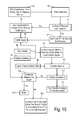
- FIG. 15 is a flowchart showing control policy execution in greater detail.
- a vehicle apparatus 10 includes various components for implementing a speed advisory and/or control system for achieving improved fuel economy.
- a sensors and data collection block 11 uses commonly available devices and interconnections to supply and communicate various items of information as described below.
- a block 12 is a road grade and speed/traffic estimator that characterizes the current driving conditions of the vehicle for use by a speed set-point calculator 13 .
- Road grade may be determined by GPS measurements, by using other sensors such as an inclinometer or pitch sensor or calculated from accelerometer measurements, or by estimating it from other commonly available vehicle data such as from load and vehicle speed information provided by the powertrain control strategy.
- Speed or density of surrounding traffic can be measured using a radar or camera that may be provided as part of an adaptive cruise control system or vehicle guidance system, or may be obtained from an off-board information source via a wireless data network, for example.
- Calculator 13 implements a control policy that determines periodic changes to a speed set-point which are communicated to an adaptive cruise control block 14 .
- Block 14 compares actual vehicle speed with the speed set-point and sends corresponding commands to a throttle control 15 (in the case of a spark-ignited internal combustion engine).
- FIG. 2 depicts a driving situation in which host vehicle 10 is traveling on a roadway 16 behind a lead vehicle 17 and in the presence of other traffic 18 .
- vehicle 10 may follow an operator determined speed set-point until it is deactivated by the operator.
- vehicle 10 may detect the presence of vehicle 17 and then reduce the speed set-point to prevent a close approach to lead vehicle 17 .
- a particular speed set-point may be followed without regard to optimizing fuel economy which is affected by variations in road grade and/or traffic conditions as the vehicle travels.
- FIG. 3 shows an approach to vehicle control wherein an optimized speed profile can be generated which improves fuel efficiency.
- the approach is known as a stochastic optimal control that applies stochastic dynamic programming (SDP) to models of fuel consumption, travel time and following distance, and the various grade and traffic conditions that affect efficiency, time, and following distance.
- SDP stochastic dynamic programming
- a transition probability model is made as a characterization of the predictable patterns in traffic speed and road grade for a particular region.
- Models of fuel consumption (e.g., for a particular model of vehicle) and travel time to reach a destination are constructed in step 21 based on road grade, a driver specified vehicle speed setpoint, traffic speed and other conditions.
- SDP stochastic dynamic programming
- a benefit of this approach is that it does not assume advanced knowledge of the route to be travelled, only that the vehicle is being driven in a specific geographic region.
- the objective is to determine a control policy which, on one hand, is responsive only to current operating conditions (as is the case for the conventional powertrain control strategy), but on the other hand, provides best on-average performance when travelling frequently in this region.
- a vehicle speed set-point is desired which achieves an optimal trade-off between expected average fuel economy and expected average travel speed.
- the region's terrain and traffic properties are characterized in the transition probabilities of a Markov chain.
- the next state of the process only depends on the current state of the process.
- the next state can be predicted using just the probability distribution of the current state and conditional probabilities of the transition between the current state and all possible next states.
- the transition probabilities can be assembled into a square matrix, called the Transition Probability Matrix (TPM), with the dimension equal to the number of states. Each row of this matrix corresponds to a specific state and contains the transition probabilities from this state to all other states.
- TPM Transition Probability Matrix
- the transition probability between two states can be approximated from the observed frequencies of the transitions in the experimental data.
- the parameters to be modeled using the TPMs can be any that are used as inputs to the models for fuel efficiency, travel time, or other performance measures to be optimized.
- the modeled parameters may typically include road grade, vehicle speed, and vehicle acceleration.
- the formation of discrete Markov chains from continuously varying parameters may be done as described in Filev et al., “A Generalized Markov Chain Modeling Approach for On Board Applications,” The 2010 International Joint Conference on Neural Networks ( IJCNN ), pp. 1-8, July 2010.
- FIGS. 4 and 5 illustrate example transition probabilities in the form of transition probability models (TPM) of road grade for a specific geographical region.
- FIG. 4 corresponds to road grade transition probabilities while driving on highways
- FIG. 5 corresponds to road grade transition probabilities for city (i.e., non-highway) driving in the geographic region. Since the majority of transitions occur between states that are near each other, both TPMs generally show peaks coinciding with a vertical plane passing through the origin and having a slope of 1. Since (for this example) highway grades tend to be lower, TPM 24 in FIG. 4 has a relatively higher peak close to the origin as compared to TPM 25 in FIG. 5 . TPMs 24 and 25 have previously been developed during test drives by test vehicles so that the data could be used to calculate on optimized control policy to be stored in a vehicle and used when driving in the corresponding region.
- TPMs 24 and 25 have previously been developed during test drives by test vehicles so that the data could be used to calculate on optimized control policy to be stored in a vehicle and used when
- FIG. 6 shows a TPM 26 showing transition probabilities between a current speed and a next speed based on data collected during an off-peak drive time (i.e., not during the rush hour).
- the resulting TPM would look different for data collected during times of a high traffic volume such as rush hour.
- W f f ( v,v + , ⁇ , ⁇ + )
- W f f ( v,v + , ⁇ , ⁇ + )
- W f f ( v,v + , ⁇ , ⁇ + )
- W f f ( v,v + , ⁇ , ⁇ + )
- W f f ( v,v + , ⁇ , ⁇ + )
- v + is the next vehicle speed (i.e., speed at the beginning of the next 30 meter segment)
- ⁇ is the current grade
- ⁇ + is the next grade (i.e., grade at the beginning of the next 30 meter segment).
- the Bayesian regularization back propagation training function trainbr available from the Neural Network tool box in MATLAB, can be applied for training the neural network model using the TPM data.
- the parameter ⁇ >0 is a weight used to trade off the fuel consumption versus the travel time.
- the SDP problem can be solved numerically by using the value iteration approach.
- V n + 1 ⁇ ( v t , ⁇ , u , ⁇ ) min u + ⁇ Q n ⁇ ( v t , ⁇ , u , u + , ⁇ ) .
- ⁇ Q n ⁇ ( v t , ⁇ , u , u + , ⁇ ) R + ⁇ v t + ⁇ ⁇ + ⁇ ⁇ qV ⁇ ( v t + , ⁇ + , u + , ⁇ ) ⁇ P ⁇ ( v t + , ⁇ +
- the value function is a function of traffic speed (i.e., a reference speed of other traffic or a speed limit if no significant traffic is present), road grade, and traffic speed offset.
- a similar “high” and “low” value for the next offset is seen for each of the other current control offset swatches.
- a matrix of all mappings covering the range of speed offsets is stored as the control policy in the vehicle and can be used to periodically update a speed set-point to achieve the desired optimization of fuel economy and travel time.
- the cost models used in calculating an optimal control policy preferably include a representation of the vehicle transmission/torque converter and the speed control system operation.
- a torque filter structure may be applied to limit the rate of change of the policy's output.
- the policy can be constructed such that its output is a constrained speed offset request to be applied to the current vehicle speed.
- KL Kullback-Leibeler
- the KL divergence is a measure of the error if process B were to be estimated by probability distribution P.
- the entries in Q can be assumed to be greater than zero if the corresponding entries of P are greater than zero. If Q is constructed using experimental data and does not satisfy this property, we replace it with
- KL divergence to zero is a measure of the expected error if using one TPM to predict the states evolving according to the transition probabilities of the other TPM.
- a vehicle control system 30 is coupled to a human machine interface (HMI) 31 , and includes sensors 32 , powertrain control module (PCM) 33 , data memory 34 , and an optional external data communication interface 35 .
- a database 36 which may be on-board or off-board of the vehicle, includes a plurality of transition probability matrices 37 and a plurality of corresponding control policies 38 .
- a current TPM Host of the host vehicle is used in conjunction with TPM database 37 in order to select or create a control policy CP Host for the host from control policy database 38 .
- Sensors 32 include any devices necessary for characterizing the driving conditions associated with TPM selection/creation such as any necessary for characterizing road grade, time of day, vehicle speed, and/or traffic speed and density.
- Memory 34 may store databases 37 and 38 and/or may provide working memory when compiling data for constructing new TPMs during routine driving of the vehicle. As described in more detail below, once sufficient data exists to create a host TPM (TPM Host ), then it may be compared using KL divergence with a plurality of transition probability models TPM a through TPM n . If a matching TPM is found, a corresponding control policy CP a through CP n is used to select a host control policy CP Host to use in optimizing a speed control during the routine driving for which the selected TPM holds true.
- FIG. 10 shows some preferred dimensions that can be used for defining a driving state to be represented in a particular transition probability model.
- a table 40 includes columns for each respective dimension, including geographic region, city/highway driving, time of day, vehicle type, and follow distance behind lead vehicle (i.e., aggressive or passive driving style).
- Each row in table 40 contains a particular value for each of the dimensions (i.e., defines a driving state which is used as an index to a respective TPM).
- a first row corresponds to the geographic region being a City A, the type of driving being City driving, the time of day being rush hour, the particular vehicle model being Model Z, and the target following distance being expressed as C seconds.
- Some of the dimensions may be constant for a particular control unit such as a vehicle type.
- Others may be measured on-board the vehicle using sensors, and some such as geographic region and time of day may be selected manually by the vehicle operator, or may be determined in response to other variables (e.g., following distance which may be determined based on the user selection of a desired vehicle spacing or may be calculated by the controller according to variables such as traffic density or time of day).
- Each particular row in table 40 identifies a corresponding TPM which may already be contained within a stored database or may be constructed in real time onboard a vehicle.
- FIG. 11 One preferred method of the invention is shown in FIG. 11 wherein a current driving state of the vehicle is determined in step 41 . This determination is based on identifying each of the dimensions such as time of day and geographic region in order to try to identify an applicable TPM. If a TPM exists for the current driving conditions, then a corresponding control policy is obtained in step 42 . Thus, optimization of the fuel economy can begin as soon as an appropriate control policy is found.
- an onboard observed TPM is populated with collected sensor data in step 43 so that the TPM database can be refined and/or expanded over time.
- the building up of the onboard TPM database may include off-board data obtained by the vehicle from a centralized database location. This database may include transition events for the matching driving state (i.e., same region, time of day, etc.) determined by other consumers' vehicles or by the vehicle manufacturer using test vehicles. If a control policy has not already been identified for the current driving state, a check is made in step 44 to determine whether adequate TPM data has been collected. If not, then a return is made to step 43 .
- step 45 determines whether the TPM is close to an existing TPM in the database. The check for similarity is based on the KL divergence described above. If the KL divergence is sufficiently small with another existing TPM, then a control policy corresponding to that similar TPM is implemented in step 46 . If there is no existing control policy sufficiently close to the current driving state, then stochastic dynamic programming is used in step 47 to create a new control policy according to the optimization process described above. Sufficient computing resources can be provided on vehicle to perform the optimization or off-board resources can be used if wireless data communication is available in the vehicle. Once a new control policy is created, it is stored and implemented in step 48 .
- a vehicle system After a vehicle system checks its GPS coordinates and the time of day, it locates an appropriate control policy to use. Once the policy is found, the vehicle will load it and begin to use it. The vehicle will read in current vehicle speed, road grade, and relative distance between it and a leading traffic vehicle, and, using the policy, will decide on a speed adjustment to make in order to obtain improved fuel economy. Using its current offset from the traffic (calculated as the difference between the lead vehicle and the host vehicle speed) to determine a next command traffic speed offset as specified by the control policy, the system determines the necessary input to supply to the vehicle throttle control to obtain the specified speed offset.
- FIG. 12 An embodiment of a general process by which an actual control policy may be computed and refined onboard a vehicle according to the driving state (e.g., a given location and time of day) is shown in FIG. 12 .
- the system looks at where the vehicle is, what the time of day is, and what type of vehicle it is. This provides a means to reference and index the control policies for later use. The system then checks whether or not a control policy already exists for these conditions in step 53 . If the policy does exist, then the system will load this policy in step 54 and update it if necessary. Such updating essentially checks how accurate the TPM is for the given region.
- TPM already exists for the region but it was developed with a set of data that was not particularly rich (e.g., not enough grade information or the traffic patterns in the given region have shifted over time) then the existing TPM can be expanded with new data collected on-board the vehicle. After the TPM is updated, a new control policy would then have to be calculated.
- step 55 When no policy currently exists for a given region, time of day, and vehicle type, the system will collect data regarding the terrain is step 55 . This data will be used to calculate the grade along a route and then the grade will be used to generate statistical models that stochastically represent the grade in step 56 . If previously collected data (from step 57 ) or data from an online database (from step 58 ) are available, this data will be incorporated into the current data and will be used in generating the statistical model in step 56 . Once the statistical model is generated, the next step is to calculate the control policy and the value function associated with the control policy.
- a cost function is calculated in step 61 as a function of fuel consumption mapping W f , travel time T f , and relative distance D between the following host vehicle and the leading traffic vehicle from steps 62 - 64 , respectively.
- the fuel consumption mapping is itself a function of vehicle speeds and road grade.
- a control policy is calculated using stochastic dynamic programming in step 60 .
- the policy will be indexed by current road grade, current vehicle speed, and current relative distance.
- the policy output is preferably generated as an offset from the current traffic speed. After calculating the control policy, it is stored for later use in step 65 .
- step 70 the vehicle collects terrain and traffic flow data.
- the vehicle system generates and updates Markov chains from this data in step 71 .
- the data must stabilize and converge.
- the vehicle system will periodically compare current versions of the Markov chain with older versions of itself in step 72 using the Kullback-Leibler (KL) divergence. When the KL divergence is sufficiently small, the chain will have converged. If the chain has not converged, the vehicle will continue collecting data in step 73 and check for convergence at a later time.
- KL Kullback-Leibler
- the vehicle system will again use the KL divergence in step 74 to see if this new chain has a similarity to any previously recorded Markov chains on-board the vehicle. If there is a chain that is suitably similar (e.g., the divergence is less than a threshold), the vehicle system will load this chain and the associated control policy or policies in step 76 . If no chain exists that is suitably similar, the vehicle will save this chain for use at a later time in step 75 .
- the vehicle will assess whether the traffic flow is continuing to be regularly predictable and is, in fact, safe for using the policy in step 77 .
- the required regularity may be detected according to the accelerations of the surrounding traffic vehicles and comparing the predicted output from the vehicle speed Markov models to the actual vehicle speeds of the traffic flow. If the traffic vehicles are accelerating a lot, this could indicate a traffic flow that is not statistically regular and could, perhaps, be a problem for operating this system in. Likewise, if the traffic speed is not consistent with what the Markov model is predicting, this could indicate that the traffic pattern has shifted over time or that the initial collection of the data was not sufficiently rich to properly model the traffic dynamics.
- step 78 If traffic is behaving out of the ordinary (due to an accident, construction, etc) that is affecting what would be considered the statistically regular flow, then this system might not accurately predict what traffic will do next. If the traffic flow continues to be safe, the policy will continue to be implemented in step 78 and periodic safety checks will be made. If the traffic flow is potentially not safe for using the control policy, the driver will be advised to move to a safer location in the traffic flow in step 79 .
- FIG. 14 shows one embodiment of a general method for updating both the centralized TPM (Markov chain) database and the vehicle control system in the event that a full-time data connection is not available in the vehicle.
- TPM Markov chain
- the designated update station can be a dealership when servicing the vehicle or can be the driver's home or any other location where a LAN connection can be made with the vehicle system so that it can connect to the central database.
- step 80 it will assess in step 80 whether an update is necessary (i.e., whether there are any new Markov chains stored on the vehicle). If not, then no update will take place as shown in step 81 . If yes, the vehicle will connect with the database in step 82 . Once a connection is established, the vehicle will check for similarity between the new chain or chains with the chains stored on the database. If suitably similar chains exist, the vehicle will download these chains and the control policies associated with them in step 83 . If there are no suitably similar Markov chains, the central database will save the new chain and then may perform an optimization for the new statistical model in step 84 . The resulting new control policy is downloaded to the vehicle in step 85 while also saving the policy in the central database for sharing with other vehicles that subsequently perform routine driving in the same driving state (e.g., region, time of day, vehicle type).
- the vehicle will connect with the database in step 82 . Once a connection is established, the vehicle will check for similarity between the new chain or chains with the chains stored on the database. If suit
- FIG. 15 One preferred embodiment of in-vehicle, real-time execution of a control policy is shown in greater detail in FIG. 15 .
- the vehicle checks its GPS coordinates, time of day, and city or highway driving conditions in order to find the appropriate policy to use in steps 89 and 90 . Once the policy is found, the vehicle will load it and begin to use it.
- the vehicle system then checks to see if there is a physical lead vehicle in front of it in step 91 . This check may preferably be made regardless of whether the vehicle has an adaptive cruise control engaged, because even if the speed is not being actively controlled it may still be desirable to provide messages to the driver to inform them of actions that could be taken to improve their fuel economy.
- step 92 the vehicle system will adopt the lead vehicle's speed as the traffic speed in step 92 . If no lead vehicle is present (or the vehicle does not have a sensor for detecting a lead vehicle), then in step 93 the vehicle system uses a driver-specified speed setpoint, historical data for the traffic speed, or the posted speed limit if no driver-specified setpoint or historical data are available. In step 95 , the vehicle will then read in the current traffic speed from step 94 , road grade from step 96 , and relative distance (between the following host vehicle and the leading traffic vehicle) from step 97 . Using the selected control policy, the system determines in step 95 the next speed offset to be executed or suggested to the driver.
- the vehicle system uses its current offset from traffic from step 99 (calculated as the difference between the lead vehicle speed and the follow vehicle speed) together with the commanded traffic speed offset given by the policy in step 95 in order to calculate an input for the vehicle's speed control in step 98 .
- the system controller Before sending this input to the speed control, the system controller will first gauge whether this action is executable (i.e., ensures that the speed offset falls within safe boundaries) in step 100 . The decision may be based on an arbitration algorithm that evaluates the outcome of the SDP optimization algorithm with respect to safety and feasibility rules and thresholds so that the resulting vehicle travel will not violate any distance constraints for vehicle separation. If the action is safe, a corresponding command will be sent to the throttle control in step 101 .
- the action is not safe, the input will be held and the vehicle will attempt to deduce why this action would be unsafe to pursue. There are two potential reasons why this action would not be safe to pursue.
- the first case is the relative distance between the lead and follow vehicles (i.e., either the current distance or the expected distance after actuating this command will be too short)—which is detected in step 102 . If this is the case, the vehicle will apply the brakes in step 103 so that it moves to a safe distance.
- the second case is when the traffic flow is not moving according to the predictions made by the current statistical model of the traffic flow (such as due to road construction, an accident, an inaccurate model, or anything other factor that would change the flow of traffic). If this is the case, the vehicle advises the driver in step 104 to relocate to a safer area of the traffic flow or to wait for the traffic flow to become statistically regular to return to using the policy output.
Abstract
Description
W f =f(v,v +,θ,θ+)
where Wf is the fuel consumption over some specified segment of distance or time (taken as a 30 meter segment in this example), where is the current vehicle speed, v+ is the next vehicle speed (i.e., speed at the beginning of the next 30 meter segment), θ is the current grade, and θ+ is the next grade (i.e., grade at the beginning of the next 30 meter segment).
W f=σ2(w 2σ1(w 1 u+b 1)+b 2),
where σ1 and σ2 are hyperbolic and linear activation functions respectively, w2 and w1, b2 and b1 are the corresponding vectors of weights and biases of the hyperbolic and linear activation functions, and u=(v, v+, v+−v, θ, θ+)′ is the vector of TPM model inputs. The Bayesian regularization back propagation training function trainbr, available from the Neural Network tool box in MATLAB, can be applied for training the neural network model using the TPM data.
where u+ (next vehicle speed offset relative to traffic) is the decision variable (i.e., control variable). The approximation is justified given that the transition probability matrix for traffic speed is close to being diagonal. The transitional cost is of the form,
R=
where
The parameter λ>0 is a weight used to trade off the fuel consumption versus the travel time.
and q, 0<q<1 is a discount factor. By assuming statistical independence of traffic speed and road grade,
P(v t +,θ+ |v t,θ)=P(v t + |v t)P(θ+|θ).
The optimal control policy is a minimizer of the above, which is
The value function iterations have the following form,
with O(vt,θ,u) denoting the set of feasible next speeds offsets. Under typical assumptions, the function will converge. The computational iterations are performed until a termination criterion
∥V n-1(•)−V n(•)∥≦CT,
is satisfied where CT is a defined convergence threshold.
where P* denotes the steady-state probability distribution of the TPM P, x and x+ are the current and next states respectively, and the summations occur over all possible states. The distribution P* can be associated with the eigenvector of the matrix P corresponding to the eigenvalue of 1, i.e.,
(P*)T P=(P*)T
where (P*)T denotes the transpose of P*.
where is a parameter between 0 and 1 (=0.0001 is used herein), n is the number of states in the TPM, and E is an n by n matrix of ones. In the replacement, a non-zero transition probability is guaranteed between any two states, even though this transition probability may be vanishingly small.
-
- 1. The KL divergence is always non-negative;
- 2. KL(P,Q)=0 if, and only if, P=Q;
- 3. KL(P, Q)≠KL(Q, P), in general. That is, the KL divergence is not symmetric.
Claims (15)
Priority Applications (1)
| Application Number | Priority Date | Filing Date | Title |
|---|---|---|---|
| US13/777,049 US8930116B2 (en) | 2013-02-26 | 2013-02-26 | On-board real-time speed control setpoint variation using stochastic optimization |
Applications Claiming Priority (1)
| Application Number | Priority Date | Filing Date | Title |
|---|---|---|---|
| US13/777,049 US8930116B2 (en) | 2013-02-26 | 2013-02-26 | On-board real-time speed control setpoint variation using stochastic optimization |
Publications (2)
| Publication Number | Publication Date |
|---|---|
| US20140244130A1 US20140244130A1 (en) | 2014-08-28 |
| US8930116B2 true US8930116B2 (en) | 2015-01-06 |
Family
ID=51388983
Family Applications (1)
| Application Number | Title | Priority Date | Filing Date |
|---|---|---|---|
| US13/777,049 Active 2033-07-15 US8930116B2 (en) | 2013-02-26 | 2013-02-26 | On-board real-time speed control setpoint variation using stochastic optimization |
Country Status (1)
| Country | Link |
|---|---|
| US (1) | US8930116B2 (en) |
Cited By (7)
| Publication number | Priority date | Publication date | Assignee | Title |
|---|---|---|---|---|
| CN105740793A (en) * | 2016-01-26 | 2016-07-06 | 哈尔滨工业大学深圳研究生院 | Road bump condition and road type identification based automatic speed adjustment method and system |
| US9637111B2 (en) * | 2015-06-09 | 2017-05-02 | Mitsubishi Electric Research Laboratories, Inc. | Method and system for selecting power sources in hybrid electric vehicles |
| US10406917B2 (en) | 2017-08-28 | 2019-09-10 | Ford Global Technologies, Llc | Systems and methods for vehicle cruise control smoothness adaptation |
| US10839302B2 (en) | 2015-11-24 | 2020-11-17 | The Research Foundation For The State University Of New York | Approximate value iteration with complex returns by bounding |
| US11022981B2 (en) | 2017-10-31 | 2021-06-01 | Cummins Inc. | Control architecture for predictive and optimal vehicle operations in a single vehicle environment |
| US11068815B2 (en) | 2018-04-10 | 2021-07-20 | Beijing Didi Infinity Technology And Development Co., Ltd. | Systems and methods for vehicle scheduling |
| US11186277B2 (en) * | 2018-10-09 | 2021-11-30 | Peter H. Bauer | Energy-optimal adaptive cruise controller |
Families Citing this family (22)
| Publication number | Priority date | Publication date | Assignee | Title |
|---|---|---|---|---|
| US9352650B2 (en) | 2013-12-12 | 2016-05-31 | Ford Global Technologies, Llc | Rule-based cruise control system and method |
| US9616898B2 (en) * | 2013-12-12 | 2017-04-11 | Ford Global Technologies, Llc | System and method for determining effective road grade characteristic |
| US9764812B1 (en) | 2014-05-16 | 2017-09-19 | Brunswick Corporation | Systems and methods for setting engine speed using a feed forward signal |
| DE102014214140A1 (en) * | 2014-07-21 | 2016-01-21 | Zf Friedrichshafen Ag | Method for the predictive control of a cruise control system of a motor vehicle |
| US9643616B2 (en) * | 2014-08-13 | 2017-05-09 | Toyota Motor Engineering & Manufacturing North America, Inc. | Systems and methods for providing predictive vehicle dynamics |
| DE102015202216A1 (en) * | 2014-09-19 | 2016-03-24 | Robert Bosch Gmbh | Method and device for operating a motor vehicle by specifying a desired speed |
| US20160148136A1 (en) * | 2014-11-24 | 2016-05-26 | Boyi Ni | Multiple sequential planning and allocation of time-divisible resources |
| US10054062B1 (en) | 2014-12-15 | 2018-08-21 | Brunswick Corporation | Systems and methods for controlling an electronic throttle valve |
| US9555869B1 (en) | 2015-01-30 | 2017-01-31 | Brunswick Corporation | Systems and methods for setting engine speed in a marine propulsion device |
| DE102015109680B4 (en) * | 2015-06-17 | 2021-07-01 | Technische Hochschule Ingolstadt | AUTOMATIC LENGTH CONTROL OF MOTOR VEHICLES |
| EP3144197B1 (en) * | 2015-09-15 | 2021-07-14 | Ford Global Technologies, LLC | Method for automatically adapting acceleration in a motor vehicle |
| US10699566B2 (en) * | 2016-03-11 | 2020-06-30 | Ford Global Technologies, Llc | Method and apparatus for congestion reduction through cooperative adaptive cruise control |
| US9957028B1 (en) * | 2016-07-15 | 2018-05-01 | Brunswick Corporation | Methods for temporarily elevating the speed of a marine propulsion system's engine |
| DE102016214822B4 (en) * | 2016-08-10 | 2022-06-09 | Audi Ag | Method for assisting a driver in driving a motor vehicle |
| US11285927B2 (en) | 2018-09-26 | 2022-03-29 | Uatc, Llc | Brake preload system for autonomous vehicles |
| US11161465B2 (en) * | 2018-10-15 | 2021-11-02 | Ford Global Technologies, Llc | Method and apparatus for improved vehicle control accommodating fuel economy |
| JP7176376B2 (en) * | 2018-11-30 | 2022-11-22 | トヨタ自動車株式会社 | vehicle controller |
| JP7205383B2 (en) * | 2019-05-28 | 2023-01-17 | 株式会社デンソー | vehicle controller |
| WO2020259828A1 (en) * | 2019-06-26 | 2020-12-30 | Volvo Truck Corporation | A method for controlling a vehicle |
| US11257387B2 (en) * | 2020-03-20 | 2022-02-22 | Honeywell International Inc. | Systems and methods for automatic sequencing behind preceding aircraft on approach |
| CN113682302B (en) * | 2021-08-03 | 2023-04-18 | 中汽创智科技有限公司 | Driving state estimation method and device, electronic equipment and storage medium |
| US20230048365A1 (en) * | 2021-08-11 | 2023-02-16 | Here Global B.V. | Corrected trajectory mapping |
Citations (25)
| Publication number | Priority date | Publication date | Assignee | Title |
|---|---|---|---|---|
| US5933100A (en) | 1995-12-27 | 1999-08-03 | Mitsubishi Electric Information Technology Center America, Inc. | Automobile navigation system with dynamic traffic data |
| US6321162B1 (en) | 1997-10-25 | 2001-11-20 | Robert Bosch Gmbh | Method for taking into account supplementary traffic information in an onboard travel control system |
| US6374173B1 (en) | 1999-05-28 | 2002-04-16 | Freightliner Llc | Terrain adaptive cruise control |
| US6480783B1 (en) | 2000-03-17 | 2002-11-12 | Makor Issues And Rights Ltd. | Real time vehicle guidance and forecasting system under traffic jam conditions |
| US6990401B2 (en) | 2002-10-04 | 2006-01-24 | Daimlerchrysler Ag | Predictive speed control for a motor vehicle |
| US7289039B2 (en) | 2004-09-10 | 2007-10-30 | Xanavi Informatics Corporation | Apparatus and method for processing and displaying traffic information in an automotive navigation system |
| US20070265759A1 (en) | 2006-05-09 | 2007-11-15 | David Salinas | Method and system for utilizing topographical awareness in an adaptive cruise control |
| US20080114521A1 (en) | 2006-11-13 | 2008-05-15 | Jeff Doering | Engine Response Adjustment Based on Traffic Conditions |
| US7383154B2 (en) | 2005-12-14 | 2008-06-03 | Gm Global Technology Operations, Inc. | Method for assessing models of vehicle driving style or vehicle usage model detector |
| US7440843B2 (en) | 2003-07-29 | 2008-10-21 | Aisin Aw Co., Ltd. | Car traffic information notification system, car traffic information notification method, and navigation system |
| US20090271084A1 (en) | 2008-04-28 | 2009-10-29 | Toyota Jidosha Kabushiki Kaisha | Cruise control system and cruise control method |
| US20090276135A1 (en) | 2005-06-07 | 2009-11-05 | Markus Hagemann | Adaptive cruise controller having dynamics matching as a function of the situation |
| US7706966B2 (en) * | 2005-12-26 | 2010-04-27 | Aisin Aw Co., Ltd. | Navigation systems, methods, and programs |
| US7774123B2 (en) | 2002-11-21 | 2010-08-10 | Lucas Automotive Gmbh | System for influencing the speed of a motor vehicle |
| US20100204896A1 (en) | 2009-02-06 | 2010-08-12 | Gm Global Technology Operations, Inc. | Cruise control systems and methods with adaptive speed adjustment rates |
| US7859392B2 (en) | 2006-05-22 | 2010-12-28 | Iwi, Inc. | System and method for monitoring and updating speed-by-street data |
| US7899610B2 (en) | 2006-10-02 | 2011-03-01 | Inthinc Technology Solutions, Inc. | System and method for reconfiguring an electronic control unit of a motor vehicle to optimize fuel economy |
| US8023883B1 (en) * | 2005-12-28 | 2011-09-20 | The Directv Group, Inc. | Method and apparatus for controlling handoffs in a mobile system |
| US8060606B2 (en) | 1999-05-03 | 2011-11-15 | Digital Envoy, Inc. | Geo-intelligent traffic reporter |
| GB2480877A (en) | 2010-06-04 | 2011-12-07 | Mir Immad Uddin | Engine control unit which uses vehicle position data to control the engine speed |
| US20120176234A1 (en) | 2011-01-10 | 2012-07-12 | Bendix Commercial Vehicle Systems, Llc | Acc and am braking range variable based on internal and external factors |
| US20120197504A1 (en) | 2010-12-23 | 2012-08-02 | Cummins Intellectual Property, Inc. | System and method of vehicle speed-based operational cost optimization |
| US8265850B2 (en) | 2009-02-02 | 2012-09-11 | GM Global Technology Operations LLC | Method and apparatus for target vehicle following control for adaptive cruise control |
| US20120239282A1 (en) | 2009-12-17 | 2012-09-20 | Toyota Jidosha Kabushiki Kaisha | Vehicle control device |
| US8825369B2 (en) * | 2008-10-14 | 2014-09-02 | Lg Electronics Inc. | Telematics terminal and method for controlling vehicle using the same |
-
2013
- 2013-02-26 US US13/777,049 patent/US8930116B2/en active Active
Patent Citations (25)
| Publication number | Priority date | Publication date | Assignee | Title |
|---|---|---|---|---|
| US5933100A (en) | 1995-12-27 | 1999-08-03 | Mitsubishi Electric Information Technology Center America, Inc. | Automobile navigation system with dynamic traffic data |
| US6321162B1 (en) | 1997-10-25 | 2001-11-20 | Robert Bosch Gmbh | Method for taking into account supplementary traffic information in an onboard travel control system |
| US8060606B2 (en) | 1999-05-03 | 2011-11-15 | Digital Envoy, Inc. | Geo-intelligent traffic reporter |
| US6374173B1 (en) | 1999-05-28 | 2002-04-16 | Freightliner Llc | Terrain adaptive cruise control |
| US6480783B1 (en) | 2000-03-17 | 2002-11-12 | Makor Issues And Rights Ltd. | Real time vehicle guidance and forecasting system under traffic jam conditions |
| US6990401B2 (en) | 2002-10-04 | 2006-01-24 | Daimlerchrysler Ag | Predictive speed control for a motor vehicle |
| US7774123B2 (en) | 2002-11-21 | 2010-08-10 | Lucas Automotive Gmbh | System for influencing the speed of a motor vehicle |
| US7440843B2 (en) | 2003-07-29 | 2008-10-21 | Aisin Aw Co., Ltd. | Car traffic information notification system, car traffic information notification method, and navigation system |
| US7289039B2 (en) | 2004-09-10 | 2007-10-30 | Xanavi Informatics Corporation | Apparatus and method for processing and displaying traffic information in an automotive navigation system |
| US20090276135A1 (en) | 2005-06-07 | 2009-11-05 | Markus Hagemann | Adaptive cruise controller having dynamics matching as a function of the situation |
| US7383154B2 (en) | 2005-12-14 | 2008-06-03 | Gm Global Technology Operations, Inc. | Method for assessing models of vehicle driving style or vehicle usage model detector |
| US7706966B2 (en) * | 2005-12-26 | 2010-04-27 | Aisin Aw Co., Ltd. | Navigation systems, methods, and programs |
| US8023883B1 (en) * | 2005-12-28 | 2011-09-20 | The Directv Group, Inc. | Method and apparatus for controlling handoffs in a mobile system |
| US20070265759A1 (en) | 2006-05-09 | 2007-11-15 | David Salinas | Method and system for utilizing topographical awareness in an adaptive cruise control |
| US7859392B2 (en) | 2006-05-22 | 2010-12-28 | Iwi, Inc. | System and method for monitoring and updating speed-by-street data |
| US7899610B2 (en) | 2006-10-02 | 2011-03-01 | Inthinc Technology Solutions, Inc. | System and method for reconfiguring an electronic control unit of a motor vehicle to optimize fuel economy |
| US20080114521A1 (en) | 2006-11-13 | 2008-05-15 | Jeff Doering | Engine Response Adjustment Based on Traffic Conditions |
| US20090271084A1 (en) | 2008-04-28 | 2009-10-29 | Toyota Jidosha Kabushiki Kaisha | Cruise control system and cruise control method |
| US8825369B2 (en) * | 2008-10-14 | 2014-09-02 | Lg Electronics Inc. | Telematics terminal and method for controlling vehicle using the same |
| US8265850B2 (en) | 2009-02-02 | 2012-09-11 | GM Global Technology Operations LLC | Method and apparatus for target vehicle following control for adaptive cruise control |
| US20100204896A1 (en) | 2009-02-06 | 2010-08-12 | Gm Global Technology Operations, Inc. | Cruise control systems and methods with adaptive speed adjustment rates |
| US20120239282A1 (en) | 2009-12-17 | 2012-09-20 | Toyota Jidosha Kabushiki Kaisha | Vehicle control device |
| GB2480877A (en) | 2010-06-04 | 2011-12-07 | Mir Immad Uddin | Engine control unit which uses vehicle position data to control the engine speed |
| US20120197504A1 (en) | 2010-12-23 | 2012-08-02 | Cummins Intellectual Property, Inc. | System and method of vehicle speed-based operational cost optimization |
| US20120176234A1 (en) | 2011-01-10 | 2012-07-12 | Bendix Commercial Vehicle Systems, Llc | Acc and am braking range variable based on internal and external factors |
Non-Patent Citations (7)
| Title |
|---|
| Desjardins, et al., Cooperative Adaptive Cruise Control: A Reinforcement Learning Approach, IEEE Transactions on Intelligent Transporation Systems, vol. 12, No. 4, Dec. 2011, pp. 1248-1260. |
| Filev, et al., "A generalized Markov Chain modeling approach for on board applications," Neural Networks (IJCNN), The 2010 International Joint Conference on , vol., No., pp. 1-8, Jul. 18-23, 2010. |
| Kolmanovsky, et al., "Stochastic optimal control of systems with soft constraints and opportunities for automotive applicants," Control Applications, (CCA) & Intelligent Control, (ISIC), 2009 IEEE, vol., No., pp. 1265-1270, Jul. 8-10, 2009. |
| Kolmanovsky, et al., Terrain and Traffic Optimized Vehicle Speed Control, 2010, pp. 378-383. |
| Lin, et al., "A stochastic control strategy for hybrid electric vehicles," American Control Conference, 2004. Proceedings of the 2004, vol. 5, No., pp. 4710-4715 vol. 5, Jun. 30, 2004-Jul. 2, 2004. |
| McDonogh, et al., "Stochastic dynamic programming control policies for fuel efficient in-traffic driving," American Control Conference (ACC), 2012, vol., No., pp. 3986-3991, Jun. 27-29, 2012. |
| McDonough, et al., "Modeling of vehicle driving conditions using transition probability models," Control Applications (CCA), 2011 IEEE International Conference on, vol., No., pp. 544-549, Sep. 28-30, 2011. |
Cited By (7)
| Publication number | Priority date | Publication date | Assignee | Title |
|---|---|---|---|---|
| US9637111B2 (en) * | 2015-06-09 | 2017-05-02 | Mitsubishi Electric Research Laboratories, Inc. | Method and system for selecting power sources in hybrid electric vehicles |
| US10839302B2 (en) | 2015-11-24 | 2020-11-17 | The Research Foundation For The State University Of New York | Approximate value iteration with complex returns by bounding |
| CN105740793A (en) * | 2016-01-26 | 2016-07-06 | 哈尔滨工业大学深圳研究生院 | Road bump condition and road type identification based automatic speed adjustment method and system |
| US10406917B2 (en) | 2017-08-28 | 2019-09-10 | Ford Global Technologies, Llc | Systems and methods for vehicle cruise control smoothness adaptation |
| US11022981B2 (en) | 2017-10-31 | 2021-06-01 | Cummins Inc. | Control architecture for predictive and optimal vehicle operations in a single vehicle environment |
| US11068815B2 (en) | 2018-04-10 | 2021-07-20 | Beijing Didi Infinity Technology And Development Co., Ltd. | Systems and methods for vehicle scheduling |
| US11186277B2 (en) * | 2018-10-09 | 2021-11-30 | Peter H. Bauer | Energy-optimal adaptive cruise controller |
Also Published As
| Publication number | Publication date |
|---|---|
| US20140244130A1 (en) | 2014-08-28 |
Similar Documents
| Publication | Publication Date | Title |
|---|---|---|
| US8930116B2 (en) | On-board real-time speed control setpoint variation using stochastic optimization | |
| US8930115B2 (en) | Efficiency-based speed control with traffic-compatible speed offsets | |
| CN108698595B (en) | For controlling the method for vehicle movement and the control system of vehicle | |
| US20210213933A1 (en) | Systems, apparatus and methods to improve plug-in hybrid electric vehicle energy performance by using v2c connectivity | |
| US8965597B2 (en) | Road grade auto-mapping | |
| CN112292646B (en) | Control system for a vehicle, method for controlling a vehicle and non-transitory computer readable memory | |
| US10838423B2 (en) | Intelligent vehicle navigation systems, methods, and control logic for deriving road segment speed limits | |
| US20200339159A1 (en) | Automatic driving track obtaining method and apparatus | |
| CN112498366B (en) | Autonomous vehicle, control method, device, equipment and storage medium | |
| US9517771B2 (en) | Autonomous vehicle modes | |
| US10179589B2 (en) | System and method for optimizing fuel economy using predictive environment and driver behavior information | |
| US10065654B2 (en) | Online learning and vehicle control method based on reinforcement learning without active exploration | |
| US9081651B2 (en) | Route navigation with optimal speed profile | |
| CN105599768B (en) | Vehicle control including dynamic vehicle quality and road grade estimation during vehicle is run | |
| JP4952268B2 (en) | Travel control plan generator | |
| Kamal et al. | Model predictive control of vehicles on urban roads for improved fuel economy | |
| KR102461831B1 (en) | System and Method for Improving of Advanced Deep Reinforcement Learning Based Traffic in Non signalalized Intersections for the Multiple Self driving Vehicles | |
| US20130297174A1 (en) | Method and System For Utilizing The Energy Storage Provided By A Vehicle's Mass In The Form Of Potential And Kinetic Energy To Optimize Fuel Consumption | |
| JP6856575B2 (en) | Control policy learning and vehicle control method based on reinforcement learning without active search | |
| CN104010911A (en) | Method and module for determining of at least one reference value for vehicle control system | |
| CN113370987B (en) | System and method for enabling motor vehicle autopilot control in a motor vehicle | |
| Menéndez-Romero et al. | Maneuver planning for highly automated vehicles | |
| KR20230010074A (en) | System and method for controlling hybrid electric vehicle | |
| KR20220095286A (en) | Apparatus and method for determining optimal velocity of vehicle | |
| CN114987433A (en) | Hybrid electric vehicle hierarchical control method based on MPC and Q-Learning algorithm |
Legal Events
| Date | Code | Title | Description |
|---|---|---|---|
| AS | Assignment |
Owner name: THE REGENTS OF THE UNIVERSITY OF MICHIGAN, MICHIGA Free format text: ASSIGNMENT OF ASSIGNORS INTEREST;ASSIGNORS:FILEV, DIMITAR P.;MICHELINI, JOHN O.;SZWABOWSKI, STEVEN J.;AND OTHERS;SIGNING DATES FROM 20130214 TO 20130222;REEL/FRAME:029876/0062 Owner name: FORD GLOBAL TECHNOLOGIES, LLC, MICHIGAN Free format text: ASSIGNMENT OF ASSIGNORS INTEREST;ASSIGNORS:FILEV, DIMITAR P.;MICHELINI, JOHN O.;SZWABOWSKI, STEVEN J.;AND OTHERS;SIGNING DATES FROM 20130214 TO 20130222;REEL/FRAME:029876/0062 |
|
| STCF | Information on status: patent grant |
Free format text: PATENTED CASE |
|
| MAFP | Maintenance fee payment |
Free format text: PAYMENT OF MAINTENANCE FEE, 4TH YEAR, LARGE ENTITY (ORIGINAL EVENT CODE: M1551) Year of fee payment: 4 |
|
| MAFP | Maintenance fee payment |
Free format text: PAYMENT OF MAINTENANCE FEE, 8TH YEAR, LARGE ENTITY (ORIGINAL EVENT CODE: M1552); ENTITY STATUS OF PATENT OWNER: LARGE ENTITY Year of fee payment: 8 |