US8934327B2 - MBS with outer coding and adjusted frame reference - Google Patents
MBS with outer coding and adjusted frame reference Download PDFInfo
- Publication number
- US8934327B2 US8934327B2 US13/061,648 US200913061648A US8934327B2 US 8934327 B2 US8934327 B2 US 8934327B2 US 200913061648 A US200913061648 A US 200913061648A US 8934327 B2 US8934327 B2 US 8934327B2
- Authority
- US
- United States
- Prior art keywords
- transmission interval
- data blocks
- coding transmission
- encoded data
- encoded
- Prior art date
- Legal status (The legal status is an assumption and is not a legal conclusion. Google has not performed a legal analysis and makes no representation as to the accuracy of the status listed.)
- Expired - Fee Related, expires
Links
Images


Classifications
-
- H—ELECTRICITY
- H04—ELECTRIC COMMUNICATION TECHNIQUE
- H04L—TRANSMISSION OF DIGITAL INFORMATION, e.g. TELEGRAPHIC COMMUNICATION
- H04L1/00—Arrangements for detecting or preventing errors in the information received
- H04L1/0078—Avoidance of errors by organising the transmitted data in a format specifically designed to deal with errors, e.g. location
- H04L1/0083—Formatting with frames or packets; Protocol or part of protocol for error control
-
- H—ELECTRICITY
- H04—ELECTRIC COMMUNICATION TECHNIQUE
- H04L—TRANSMISSION OF DIGITAL INFORMATION, e.g. TELEGRAPHIC COMMUNICATION
- H04L1/00—Arrangements for detecting or preventing errors in the information received
- H04L1/0001—Systems modifying transmission characteristics according to link quality, e.g. power backoff
- H04L1/0023—Systems modifying transmission characteristics according to link quality, e.g. power backoff characterised by the signalling
- H04L1/0025—Transmission of mode-switching indication
-
- H—ELECTRICITY
- H04—ELECTRIC COMMUNICATION TECHNIQUE
- H04L—TRANSMISSION OF DIGITAL INFORMATION, e.g. TELEGRAPHIC COMMUNICATION
- H04L1/00—Arrangements for detecting or preventing errors in the information received
- H04L1/0001—Systems modifying transmission characteristics according to link quality, e.g. power backoff
- H04L1/0023—Systems modifying transmission characteristics according to link quality, e.g. power backoff characterised by the signalling
- H04L1/0028—Formatting
-
- H—ELECTRICITY
- H04—ELECTRIC COMMUNICATION TECHNIQUE
- H04L—TRANSMISSION OF DIGITAL INFORMATION, e.g. TELEGRAPHIC COMMUNICATION
- H04L1/00—Arrangements for detecting or preventing errors in the information received
- H04L1/004—Arrangements for detecting or preventing errors in the information received by using forward error control
- H04L1/0056—Systems characterized by the type of code used
- H04L1/0064—Concatenated codes
- H04L1/0065—Serial concatenated codes
-
- H—ELECTRICITY
- H04—ELECTRIC COMMUNICATION TECHNIQUE
- H04L—TRANSMISSION OF DIGITAL INFORMATION, e.g. TELEGRAPHIC COMMUNICATION
- H04L1/00—Arrangements for detecting or preventing errors in the information received
- H04L1/0001—Systems modifying transmission characteristics according to link quality, e.g. power backoff
- H04L1/0002—Systems modifying transmission characteristics according to link quality, e.g. power backoff by adapting the transmission rate
- H04L1/0003—Systems modifying transmission characteristics according to link quality, e.g. power backoff by adapting the transmission rate by switching between different modulation schemes
-
- H—ELECTRICITY
- H04—ELECTRIC COMMUNICATION TECHNIQUE
- H04L—TRANSMISSION OF DIGITAL INFORMATION, e.g. TELEGRAPHIC COMMUNICATION
- H04L1/00—Arrangements for detecting or preventing errors in the information received
- H04L1/0001—Systems modifying transmission characteristics according to link quality, e.g. power backoff
- H04L1/0009—Systems modifying transmission characteristics according to link quality, e.g. power backoff by adapting the channel coding
-
- H—ELECTRICITY
- H04—ELECTRIC COMMUNICATION TECHNIQUE
- H04W—WIRELESS COMMUNICATION NETWORKS
- H04W28/00—Network traffic management; Network resource management
- H04W28/02—Traffic management, e.g. flow control or congestion control
- H04W28/04—Error control
Definitions
- This disclosure relates to communication systems, and more particularly to a method and apparatus providing MBS (multicast broadcast service) with outer coding and adjusted frame reference indexing.
- MBS multicast broadcast service
- a BS Base Station
- UE User Equipment
- 802.16 and LTE
- the BS includes in its message an absolute frame number to refer to a frame where the specific activity needs to take place.
- the desired frame is indicated by the BS using a frame offset with respect to the current frame.
- absolute frame numbers has shortcoming.
- conventional base stations in a network may not synchronize their frame numbering. That is, when one BS transmits a frame numbered M 1 , a neighboring BS may be transmitting a frame numbered M 2 . Therefore, absolute frame numbers can only be used when the BS with respect to which the reference is given is known to the UE (a fixed, nomadic or mobile station). This is not always the case.
- Some examples include the following: (1) when the UE exits Idle Mode; (2) when the UE is listening to pages or broadcast announcements; and (3) when the UE is receiving an allocation at a target BS and there are several potential target BSs (as is the case in, for example, macro-diversity reception from multiple BSs).
- the frame offset method also has short comings. For example, the message that contains the frame offset needs to be received in a particular frame. This imposes constraints on the BS scheduler, which needs to ensure that the message is transmitted and received in a particular frame, as delaying transmission would result in the offset information being invalid. Furthermore, if the message is fragmented, or if the message requires multiple HARQ or ARQ retransmissions, the receiver must be able to determine when the first fragment or HARQ/ARQ transmission occurred, which complicates the implementation of the receiver.
- MCS Multicast and Broadcast Services
- IEEE802.16 and LTE support MBS (LTE uses the term MBMS (Multimedia Broadcast/Multicast Service)).
- PER Packet Error Rates
- MCS Modulation and Coding Schemes
- the subject matter disclosed herein provides methods and apparatus for wireless communications and, more particularly, MBS (multicast broadcast service) with outer coding and adjusted frame reference indexing.
- MBS multicast broadcast service
- the method includes receiving data packets from a network, dividing the data packets into one or more data streams, applying outer encoding on the one or more data streams and providing the one or more encoded data streams to an air interface for transmission to a user equipment over a wireless communication system.
- the user equipment including a receiving unit configured to receive one or more encoded data streams from a base station and a processor coupled to the receivers and configured to apply outer decoding on the one or more encoded data streams and provide the decoded data streams to a user equipment application.
- the apparatus including a controller for dividing data packets into one or more streams, applying outer encoding on the one or more streams and determining the scheduling details including MCS for simultaneous transmission of data streams by one or more base stations and a transmitter for transmitting the encoded data streams to a user equipment.
- FIG. 1 depicts a block diagram of a network including Base Stations and User Equipments;
- FIG. 2 depicts a block diagram of a User Equipment
- FIG. 3 depicts a block diagram of a Base Station
- FIG. 4 depicts an overview of the protocol stack from application to physical layer with outer-coding of application data
- FIG. 5 depicts an overview of the frame structure from application to physical layer with outer-coding of application packet data
- FIG. 6 depicts the Outer Coding Transmission Interval mapping message as it could be applied to a wireless air interface using a Time Division Duplex mode of operation.
- FIG. 1 depicts a simplified functional block diagram of an embodiment of a wireless communication system 100 .
- the wireless communication system 100 includes a plurality of base stations 110 A and 110 B, each supporting a corresponding service or coverage area 112 A and 112 B.
- the base stations are capable of communicating with wireless devices within their coverage areas.
- the first base station 110 A is capable of wirelessly communicating with a first UE 114 A and a second UE 114 B within the coverage area 112 A.
- the first UE 114 A is also within the coverage area 112 B (Sector 118 A) and is capable of communicating with the second base station 110 B.
- the communication path from the base station to the UE is referred to as a downlink 116 A and 116 B and the communication path from the UE to the base station is referred to as an uplink 116 C.
- the base stations 110 A and 110 B can be configured as cellular base station transceiver subsystems, gateways, access points, radio frequency (RF) repeaters, frame repeaters, nodes, or any wireless network entry point.
- the base stations 110 A and 110 B can be configured to support either an omnidirectional coverage area or a sectored coverage area.
- the second base station 110 B is depicted as supporting the sectored coverage area 112 B.
- the coverage area 112 B is depicted as having three sectors, 118 A, 118 B, and 118 C.
- the second base station 110 B treats each sector 118 A, B, C as effectively a distinct coverage area.
- the User Equipment 114 A and 114 B can be mobile, nomadic, or stationary units.
- the User Equipment 114 A and 114 B are often referred using alternative terminology, for example, client stations, mobile stations, mobile units, subscriber stations, wireless terminals, or the like; in this specification the term UE encompasses all these definitions.
- a User Equipment can be, for example, a wireless handheld device, a vehicle mounted device, a portable device, user or subscriber premise equipment, a fixed location device, a wireless plug-in accessory or the like.
- a User Equipment can take the form of a handheld computer, notebook computer, wireless telephone, personal digital assistant, wireless email device, personal media player, meter reading equipment or the like and may include a display mechanism, microphone, speaker and memory.
- the base stations 110 A and 110 B communicate with each other using a Network Control Module 124 over backhaul links 122 A and 122 B and in some embodiments the base stations 110 A and 110 B may also communicate directly with each other.
- the backhaul links 122 A and 122 B may include wired and wireless communication links.
- the network control module 124 provides network administration and coordination as well as other overhead, coupling, and supervisory functions including, in some embodiments, such functions as the allocation of resources and base station (e.g. BS 110 A, B) radio configuration in the wireless communication system 100 .
- the wireless communication system 100 can be configured to support both bidirectional communication and unidirectional communication.
- the UE is capable of both receiving information from and providing information to the wireless communications network.
- Applications operating over the bidirectional communications channel include traditional voice and data applications.
- a unidirectional network the UE is capable of receiving information from the wireless communications network but may have limited or no ability to provide information to the network.
- Applications operating over the unidirectional communications channel include broadcast and multicast applications.
- the wireless system 100 supports both bidirectional and unidirectional communications.
- the network control module 124 also acts as a gateway; it may be coupled to external entities via, for example, a content link 126 (e.g., a source of digital video and/or multimedia) and a two-way traffic link 128 which in turn are connected to a network 130 .
- a content link 126 e.g., a source of digital video and/or multimedia
- a two-way traffic link 128 which in turn are connected to a network 130 .
- a typical system incorporates a Management System 129 whereby the system parameters can be set and performance monitored and may be used to set parameters corresponding to data on the content link 126 and two-way traffic link 128 .
- the wireless communication system 100 can be configured (through a Network Management System 129 ).
- a Network Management System 129 typically systems used to distribute multicast and broadcast that rely on the use of Stream Identification and transmission areas are split into different zones each covering a defined geographic area, for MBS operation.
- Such zones known as MBS Zones in IEEE802.16 (or the equivalent concept in LTE known as MBMS Zones)
- Each MBS Zone has a MBS Zone ID through which it can be identified.
- MBS Zone ID may be set by the Network Control Module 124 .
- Data such as streaming data, can be marked either in the Network Control Module 124 or elsewhere in the Network 130 with a Stream Identification Code (Stream ID) to enable a stream within a given zone to be uniquely identified by receiving apparatus (e.g. UE 114 B).
- Stream ID Stream Identification Code
- the wireless communication system 100 can be configured to use Orthogonal Frequency Division Multiple Access (OFDMA) communication techniques.
- OFDMA Orthogonal Frequency Division Multiple Access
- the wireless communication system 100 can be configured to substantially comply with a standard system specification, such as IEEE 802.16 and its progeny or some other wireless standard such as, for example, WiBro, WiFi, Third Generation Partnership Project (3GPP) Long Term Evolution (LTE), or it may be a proprietary system.
- the wireless system may be operated in Frequency Division Duplex Mode (FDD) or Time Division Mode (TDD) or Hybrid FDD/TDD mode or Downlink Only Mode in paired or unpaired spectrum as appropriate.
- FDD Frequency Division Duplex Mode
- TDD Time Division Mode
- Hybrid FDD/TDD mode Hybrid FDD/TDD mode
- Downlink Only Mode in paired or unpaired spectrum as appropriate.
- a two-way mode of operation may be complemented by a one-way (downlink only) mode which may be used for MBS and
- Network Control Module 124 may be integrated into the Base Station 110 or split into two or more modules performing the functions described herein. Alternatively one or more functions described as being within the scope of the BS ( 110 A) may be distributed to a centralised module such as the Network Control Module ( 124 ). Furthermore, other network entities not depicted or described herein but known to those skilled in the art, may be required to implement a practical wireless communication system.
- IEEE 802.16 refers to one or more Institute of Electrical and Electronic Engineers (IEEE) Standard for Local and metropolitan area networks, Part 16: Air Interface for Fixed Broadband Wireless Access Systems, 1 Oct. 2004, IEEE Standard for Local and metropolitan area networks, Part 16: Air Interface for Fixed and Mobile Broadband Wireless Access Systems, 26 Feb. 2006, and any subsequent additions or revisions to the IEEE 802.16 series of standards.
- IEEE Institute of Electrical and Electronic Engineers
- LTE refers to the Long Term Evolution for UMTS being developed by the Third Generation Partnership Project (3GPP) and any subsequent revisions
- downlinks 116 A and 116 B and uplink 116 C each represent a radio frequency (RF) signal.
- the RF signal may include data, such as voice, video, images, Internet Protocol (IP) packets, control information, and any other type of information.
- IP Internet Protocol
- the RF signal may use OFDMA.
- OFDMA is a multi-user version of orthogonal frequency division multiplexing (OFDM). In OFDMA, multiple access is achieved by assigning to individual users, groups of (subcarrier, timeslot) pairs.
- the subcarriers are modulated using one or more of the following techniques: BPSK (binary phase shift keying), QPSK (quadrature phase shift keying), QAM (quadrature amplitude modulation), and carry symbols (also referred to as OFDMA symbols) and typically includes data coded using FEC (forward error-correction code) or both inner and outer FEC.
- BPSK binary phase shift keying
- QPSK quadrature phase shift keying
- QAM quadrature amplitude modulation
- carry symbols also referred to as OFDMA symbols
- FEC forward error-correction code
- FIG. 2 depicts an exemplary UE (User Equipment), which may be part of a handheld, portable or fixed station.
- the UE 114 B includes a one or more antennas 220 A-B for receiving the downlinks 116 A-B.
- the UE 114 B also includes a radio interface 240 , which may include other components, such as filters, converters (e.g., digital-to-analog converters and the like), symbol de-mappers, an Inverse Fast Fourier Transform (IFFT) module, and the like, to process symbols, such as OFDMA symbols, carried by downlinks 116 A-B.
- IFFT Inverse Fast Fourier Transform
- the UE 114 B includes means for implementing a CS to interface between the radio MAC layer and the function necessary for decoding the outer-coded application data and processing the Application Data Streams.
- the UE 114 B is also compatible with IEEE 802.16 and OFDMA.
- the UE 114 B further includes a processor 220 for controlling said UE 114 B and for accessing and executing program code stored in memory 225 .
- FIG. 3 depicts an exemplary BS according to an aspect of the present disclosure.
- the Base Station 110 A includes one or more antennas 320 A-B configured to transmit downlink signals (and in a bi-directional system also configured to receive uplink signals).
- Antenna radiation patterns may be directional or omnidirectional. More than one transmission antenna may be used for the purposes of Transmit Diversity or Multiple Input Multiple Output (MIMO) or other signal or spatial processing techniques.
- MIMO Multiple Input Multiple Output
- the Base Station also includes a radio interface 340 coupled to the antennas 320 A-B; a processor 330 for controlling the base station 110 A and for accessing and executing program code stored in memory 335 ; a Backhaul Interface module 360 that acts as an interface to the incoming backhaul link 122 between the base station 110 A and other network elements (e.g. 124 ); and a synchronisation and timing module 370 .
- the synchronization and timing module 340 may, depending upon deployment option, derive its timing from the backhaul 122 via the backhaul interface 360 or from an optional Global Positioning System module or similar satellite system module 350 when connected to its associated Antenna 351 .
- the timing module 340 provides a reference timing signal to the Controller 330 and Radio Interface 340 .
- the Outer-Coding function and Convergence Sublayer may be implemented as part of the Controller 330 or within the Radio Interface 340 or as part of a separate module (not shown).
- a ‘Stream’ is defined as a flow of information which in its entirety carries information for a media stream such as a video stream or audio stream or a combination of video, audio and hypertext.
- a Stream may be composed of several sub-streams; each sub-stream carries packets that are identically modulated and encoded at the same inner and outer code rates.
- a sub-stream may also contain the information required for extracting the application packets from all the decoded outer-code data blocks (for example packet delineation information) of a particular stream.
- An OCTI (Outer-Coding Transmission Interval) is defined as an interval of N (OFDMA) consecutive frames which every N (OFDMA) frames recur.
- the sequence of OCTIs is specific to an MBS Zone and is specified in terms of the number of frames in each OCTI (length) and the start frame of each OCTI.
- Each outer coded data block is transmitted within one OCTI.
- the OCTINS (OCTI Numbering System) is used for referencing and numbering a subset of symbols in the frames transmitted during one OCTI and the OCTINS Domain is the set of symbols within an OCTI that are referenced by the OCTINS.
- one way of referencing a particular MAC (Media Access Control) frame is the use an OCTI-MAP message to signal the mapping of outer-coded data blocks.
- This method is more robust and efficient than for example, the current MBS-MAP message used in IEEE standard 802.16.
- integration of the new message will require limited PHY changes and can co-exist with the current 16e bi-directional data services and MBS services.
- the OCTI_MAP message does not rely on DL-MAP message or the “daisy-chaining” mechanism, but is rather transmitted at configurable a-priori known locations. Furthermore, the OCTI_MAP message provides the mapping information for an entire outer-coding interval, rather than for one frame at a time, and thereby encodes the mapping information more efficiently. Next, the OCTI_MAP message specifies the MAC PDU delineation, thereby enabling the suppression of the MAC PDU headers. Also, the OCI_MAP message may optionally be re-transmitted one or more times during the outer-coding intervals, and thereby become more robust.
- the OCTI_MAP message specifies MCS and allocations in a manner that complements the outer-coding in an optimized way. For example, some aspects of the OCTI_MAP, such as the frame numbering system, could be made optional. Finally, the OCTI_MAP message provides support for sub-streams, thereby allowing for unequal protection of the application packets belonging to the same MBS stream.
- some of the parameters related to the OCTI structure are static in nature. These parameters include but are not limited to the MBS Zone ID, the fixed length of the OCTIs, a reference start frame for one OCTI with subsequent OCTIs occur at an integer multiples of the fixed OCTI length after that frame, the number and locations of the OCTI_MAP messages transmitted during an OCTI, the maximum number of symbols that the OCTI_MAP may occupy and finally, the MCS and the permutation type (PUSC or FUSC) used to encode the OCTI_MAP message.
- MCS permutation type
- MBS Zone IDs may be reused, i.e., two non-adjacent and non-overlapping zones may be identified by the same MBS Zone ID, it is assumed that the MBS Zone IDs are allocated to MBS zones in such a way that within any geographic area of adequate size for which the user equipment may be configured, each MBS zone ID identifies at most one MBS zone.
- a reference start frame for one OCTI is specified using an adjusted reference to overcome the problem that BSs within an MBS zone may not have their frame numbering synchronized.
- the OCTI-MAP message relies on the concept of a Stream ID. It is assumed that an operator allocates Stream IDs is such a way that every (MBS Zone ID, Stream ID) identifies a stream and that the mapping of (MBS Zone IDs, Stream IDs) to streams within a geographic area of adequate size is available at the application layer at the SS.
- the OCTI MAP message also allows for streams to comprise several sub-streams.
- the sub-streams are encoded into separate outer-code data blocks.
- a sub-stream may be a subset of the stream's application packets which requires a different (e.g., a more robust) outer-coding.
- a sub-stream may also contain the information required for extracting the application packets from all the decoded outer-code data blocks (such as the application packet delineation information) of a particular stream.
- one way of achieving PER suitable for broadcast or multicast video and audio applications is to add an optional outer-coding scheme to MBS/MBMS data.
- Use of this outer-coding scheme adds significant time-diversity with the purpose to operate at a higher MCS (employing higher order modulation and/or less powerful coding).
- FIG. 4 illustrates an embodiment of the outer-coding solution. It comprises processing the Application Data Streams prior to transmission in two steps; outer-coding and interfacing to the MAC layer prior to being wirelessly transmitted and subsequent reception at the UE.
- the incoming aggregate data stream 400 is divided into individual streams.
- a network element such as the Network Control Module 124 may also divide the incoming aggregate data stream into individual streams.
- Each individual incoming Application Data Packet Steam 401 A, 401 B, . . . 401 N is then outer-coded 410 , using a code such as a Reed-Solomon code, as appropriate; different codes ( 410 A, 410 B, . . . 410 N) may be used to encode different streams and within a stream unequal protection may be provided to sub-streams.
- each row of the outer code block is a Reed-Solomon (RS) codeword.
- RS codewords may be generated on a GF (Galois Field).
- a GF(256) finite field may be used.
- the systematic bytes of the codeword shall be prefixed with 255 ⁇ N 0x00 bytes.
- the encoder generates a RS(255,255 ⁇ N+K) codeword of length 255 and drops the leading 255 ⁇ N 0x00 bytes.
- the application layer packets are written into the Reed-Solomon code such that packets are interleaved across multiple Reed-Solomon codewords. They are preceded by a control block that aids in packet delineation without error propagation.
- RS Random Solomon
- padding bytes are added to the last few bytes of the data section of the table if necessary to fill the data section of the table. These are assigned the value 0x00 and are not transmitted over the air interface.
- the data from the Reed-Solomon code block is transmitted according to a method to ensure that the Reed-Solomon codewords are interleaved in time.
- column shuffling may be used to improve frequency diversity.
- this is be done in such as way as it occurs prior to the insertion of standard MAC and PHY signaling such that the standards' defined positions and formats are retained.
- the data in a column of the Reed-Solomon table must be shuffled prior to delivery of the SDU (Service Data Unit) to the MAC layer for insertion of GMH, calculation of CRC-16, and transmission.
- the presence or absence of column shuffling is indicated within a transmitted signaling message.
- the additional outer-coding such as the RS code described, enables the system to operate at lower SINR (Signal to Interference plus Noise Ratio); SINR that would otherwise result in unacceptable PER (Packet Error Rate) at the UE.
- SINR Signal to Interference plus Noise Ratio
- SINR Packet Error Rate
- a CS Convergence Sublayer
- OCD-CS Outer Coded Data Convergence Sublayer
- the BS OCD-CS supports the following: accepting the outer-coded data packets; classifying the received data packets and mapping them to the appropriate MCID (Multicast Connection ID) or equivalent; passing the data packets and associated signalling to the MAC CPS (Common Part Sublayer) or equivalent.
- the MAC layer passes the information to the PHY (Physical) Layer 440 where the resulting data is transmitted wirelessly 445 .
- PHY Physical
- MBS packets that have not been outer-coded may also be transmitted by the BS 110 A and received by UE 114 B.
- FIG. 4 depicts the UE recovering Stream 401 A and 401 B.
- a CS is used to interface the UE MAC 460 with the Outer-decoding function 490 A, B (which undoes the coding applied to the transmitted stream).
- the UE OCD-CS 470 transparently passes the received data packets and their Stream IDs (stream indications) to the outer-coding decoding function, the output of which comprise the wanted application data stream or streams.
- 495 A is the recovered version of 401 A
- 495 B is the recovered version of 401 B; assuming error free decoding the input streams and output streams will be identical
- all User Equipment designed to receive the outer-code MBS mode described herein support RS decoding on blocks of length up to 255 (in each row) with different possible combinations of systematic data and parity bytes having up to 64 parity bytes. This allows for support of different Reed Solomon combinations where the total number of data bytes plus the number of parity bytes (including possible puncturing) is less than or equal to 255.
- the UE unshuffles the data using an appropriate de-shuffling process. This is performed according to the shuffling previously applied by the BS, prior to passing the Application Data to the higher layers of the protocol stack.
- the UE 114 may combine streams from more than one BS ( 110 A, 110 B) that are time aligned and contain the same content (as indicated by for example, Stream ID, MBS Zone ID and Frame Number such as can be determined from the adjusted frame reference).
- the combination of streams transmitted from different BS in the same MBS Zone 110 A, B would have the beneficial effect of reducing PER or enabling operation at lower SINR than otherwise possible.
- FIG. 5 An embodiment using outer-coding solution is further depicted in FIG. 5 and described by way of example with reference to 802.16. Similar procedures could be applied to other standards.
- a stream of Application Packets 500 in an OCTI (‘outer-coding time interval’) 501 (time duration “TOUTER”) are outer-coded 510 and formatted to form an outer-coded MAC Packet Service Data Unit (SDU) 520 .
- the typical duration of the OCTI is on the order of hundreds of milliseconds; recognising the trade-off between processing gain and delay in a practical system a range of one hundred ms up to two seconds is envisaged.
- the application data is mapped to the MAC and PHY such that data and signaling that either does not benefit from outer-coding or is not necessary for retrieving the outer-coded data is not subject to outer-coding.
- data that is necessary for retrieving the outer-code should be very robustly coded (in the standard MAC/PHY). Further standard MAC and/or PHY layer data may be added prior to transmission.
- GMH Generic MAC Header
- PDU Protocol Data Unit
- CRC Cyclic Redundancy Check
- the stream of FEC Blocks 540 is mapped into the appropriate positions in the MBS region of the PHY layer prior to transmission 550 .
- the MBS mapping information is in region 551
- the processed Application Data group of FEC Packets 541 A is mapped to position 552
- FEC Packet 541 B is mapped to position 553 .
- Other mappings are possible.
- the effect of the above method is that data that has been outer-coded during the outer-coding interval is combined with any other coding dependent information and passed to the MAC/PHY such that information (as illustrated by the insertion of GMH and CRC in the description above) that is not outer-coded is in deterministic locations and of deterministic size.
- outer-coding can recover from missing the reception of an entire MAC PDU fragment of the outer-coder packet, unlike conventional fragmentation of SDUs into MAC PDUs, it is important to know which bytes were lost rather than merely that a particular fragment was lost. Moreover, this information can be sent as robustly as either the MBS_MAP or the outer-coded data.
- the fragmentation of outer-coder packets (MAC SDUs for the outer-coding function) into MAC PDUs does not necessarily use the fragmentation or packing subheaders, but instead uses a fragmentation byte number (FBN) in the MBS_OUTER_CODED_DATA_IE TLV in the MBS_MAP to indicate which byte of the outer-coder packet maps to the first byte of an allocation for the MCID.
- FBN fragmentation byte number
- the number of sub-burst padding bytes is included in the MBS_OUTER_CODED_DATA_IE TLV. This allows the MAC layer to use this information to strip the padding bytes before delivery to higher layers.
- the outer-coded data is transmitted along with a message specifying the outer-coded MBS allocations.
- the message includes: the length of the OCTIs (outer coded transmission interval); a reference start frame for one OCTI using the previously described method using an adjusted reference, subsequent OCTIs occurring at integer multiples of the OCTI length; the number and location of messages relevant to receiving and decoding the outer coded data during an OCTI; the MCS (Modulation and Coding Scheme) and any other information used to encode the message or necessary to locate and decode the outer-coded application data.
- MCS Modulation and Coding Scheme
- the OCTI mapping message specifies the allocations for each stream using the OCTI Numbering System (OCTINS).
- OCTINS is used to index a subset of all symbols in all Downlink sub-frames that are transmitted during one OCTI. This subset of symbols is referred to as the OCTINS domain.
- the BS schedules all the streams that belong to the MBS zone within the subset of symbols that constitute the OCTINS domain.
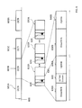
- FIG. 6 illustrates elements of the OCTI mapping message transmitted by the base station to enable the UEs to locate and decode the desired outer-coded application data.
- the OCTI mapping message is shown in the context of an OFDMA TDD system; where base station downlink transmission and uplink reception occur alternately within a physical layer frame. The principle can be equally applied to FDD systems or Downlink only systems.
- a sequence of OCTI 600 comprises individual OCTI 601 A, B, . . . n each with a fixed number of OFDMA Frames which are MBS Zone specific, contain outer-coded blocks from multiple streams and the allocations of which are specified by the OCTI Mapping message transmitted during the previous OCTI.
- Each OCTI 601 A comprises one or more OFDMA Frames 615 some of which contain the OCTINS domain data 620 .
- the OCTINS domain is made up of an integer number of OFDMA symbols and contains the outer-coded data of the streams allocated in the frame.
- An OFDMA frame 615 comprising downlink and uplink portions is illustrated.
- the OCTINS domain occupies part of the downlink allocation this results in the downlink 630 A (which may be used for purposes other than outer-coded MBS including the support of conventional MBS, the downlink of two-way services, unicast transmission, etc.) being shorter than the downlink 630 B where no OCTINS domain is present.
- the OCTINS domain may be specified by a vector, V, whose length N is less than or equal to the number of frames of the OCTI and each element is a non-negative integer less than or equal to the total number of symbols in the Downlink sub-frame.
- the OCTINS vector V signals the number of symbols in each frame that are contained in the OCTINS domain. If B is the number of frames in the OCTI and k is the number of a frame within the OCTI, thus 0 ⁇ k ⁇ B, then the OCTINS domain contains the V(k mod N) last symbols of the kth subframe. The symbols in the OCTINS domain are numbered in increasing order starting with 0.
- the BS signals the OCTINS vector in the OCTI mapping message, which enables the UE to determine which frame k and which symbol s in frame k a given number m references and, thereby, interpret the mapping information in that message.
- the UE Given an OCTINS domain symbol number m, the UE can identify which symbol s in which DL sub-frame k (where the first symbol of a DL sub-frame is numbered 0) this number references. The following steps may be used to calculate k and s given m.
- Symbols in the OCTINS domain that are not allocated to any stream may be used for other allocations, such as allocations for unicast transport.
- the uplink time durations 640 A and 640 B are unaffected by the presence or absence of the OCTINS domain.
- the OTCI sequence is MBS zone specific; each outer-coded block of each stream that is transmitted in an MBS zone is transmitted over the air interface within one OCTI.
- the OCTI period in a practical embodiment is likely to be on the order of hundreds of milliseconds; typically 100 ms to 2 seconds.
- the OCTINS is a system for numbering a subset of the symbols in one OCTI.
- a message is transmitted which specifies the mapping of outer-coded data blocks transmitted in the next outer-coding interval (rather than one frame at a time); this message may be transmitted one or more times to improve robustness; the message allows for sub-streams thereby allowing unequal protection to be applied to packets belonging to the same MBS stream.
- Resources leftover after all the MBS streams within the MBS zone are allocated may be allocated for other purposes.
- the BS periodically transmits a field to indicate the burst profile including the MCS (Modulation and Coding Scheme) in use.
- MCS Modulation and Coding Scheme
- the insertion of the adjusted (frame) reference number will be described in the context of IEEE802.16 and assuming the use of GPS timing. In IEEE802.16 this periodic field is referred to as the DCD (Downlink Channel Descriptor).
- a TLV (Type Length Value) descriptor with a Type field of 1 byte and a Value Field of 3 bytes (24 bits) representing an integer number N set to the frame number of the frame transmitted at time to, where, as previously described, to is expressed with reference to GPS time and is such that t0 mod(24 ⁇ Tf) 0 ms, where Tf is the frame duration, which is typically 5 ms and a Length field of 1 byte is contained within the DCD message.
- Other standards use different terminology; other embodiments may use different timing methods, reference clock sources including IEEE1588 and reference times; field sizes, frame duration and other parameters may differ.
- the MCS (Modulation and Coding Scheme) allocations in the PHY may be specified in a manner to optimally complement the outer-coding scheme.
- Base station 110 A (or one or more components therein) can be implemented using one or more of the following: a processor executing program code, an application-specific integrated circuit (ASIC), a digital signal processor (DSP), an embedded processor, a field programmable gate array (FPGA), and/or combinations thereof.
- User Equipment 114 B (or one or more components therein) can be implemented using one or more of the following: a processor executing program code, an application-specific integrated circuit (ASIC), a digital signal processor (DSP), an embedded processor, a field programmable gate array (FPGA), and/or combinations thereof.
- These various implementations may include implementation in one or more computer programs that are executable and/or interpretable on a programmable system including at least one programmable processor, which may be special or general purpose, coupled to receive data and instructions from, and to transmit data and instructions to, a storage system, at least one input device, and at least one output device.
- These computer programs also known as programs, software, software applications, applications, components, program code, or code
- machine-readable medium refers to any computer program product, computer-readable medium, apparatus and/or device (e.g., magnetic discs, optical disks, memory, Programmable Logic Devices (PLDs)) used to provide machine instructions and/or data to a programmable processor, including a machine readable medium that receives machine instructions as a machine-readable signal.
- PLDs Programmable Logic Devices
- systems are also described herein that may include a processor and a memory coupled to the processor.
- the memory may include one or more programs that cause the processor to perform one or more of the operations described herein.
Abstract
Description
p(x)=x 8 +x 4 +x 3 +x 2+1
Claims (18)
Priority Applications (1)
| Application Number | Priority Date | Filing Date | Title |
|---|---|---|---|
| US13/061,648 US8934327B2 (en) | 2008-09-03 | 2009-09-03 | MBS with outer coding and adjusted frame reference |
Applications Claiming Priority (4)
| Application Number | Priority Date | Filing Date | Title |
|---|---|---|---|
| US9402708P | 2008-09-03 | 2008-09-03 | |
| US61/094027 | 2008-09-03 | ||
| US13/061,648 US8934327B2 (en) | 2008-09-03 | 2009-09-03 | MBS with outer coding and adjusted frame reference |
| PCT/US2009/055916 WO2010028167A1 (en) | 2008-09-03 | 2009-09-03 | Mbs with outer coding and adjusted frame reference |
Publications (2)
| Publication Number | Publication Date |
|---|---|
| US20120033598A1 US20120033598A1 (en) | 2012-02-09 |
| US8934327B2 true US8934327B2 (en) | 2015-01-13 |
Family
ID=41797482
Family Applications (1)
| Application Number | Title | Priority Date | Filing Date |
|---|---|---|---|
| US13/061,648 Expired - Fee Related US8934327B2 (en) | 2008-09-03 | 2009-09-03 | MBS with outer coding and adjusted frame reference |
Country Status (2)
| Country | Link |
|---|---|
| US (1) | US8934327B2 (en) |
| WO (1) | WO2010028167A1 (en) |
Families Citing this family (5)
| Publication number | Priority date | Publication date | Assignee | Title |
|---|---|---|---|---|
| EP2380287B1 (en) | 2008-12-18 | 2014-09-24 | Nec Corporation | Methods and systems for conveying scheduling information of overlapping users in an OFDMA MU-MIMO system |
| CN103297183B (en) * | 2012-03-05 | 2016-02-03 | 腾讯科技(深圳)有限公司 | Data communications method and device |
| IT201700055080A1 (en) * | 2017-05-22 | 2018-11-22 | Teko Telecom S R L | WIRELESS COMMUNICATION SYSTEM AND ITS METHOD FOR THE TREATMENT OF FRONTHAUL DATA BY UPLINK |
| US11595943B2 (en) * | 2020-02-11 | 2023-02-28 | Qualcomm Incorporated | Outer coding schemes in downlink control information |
| CN115804131A (en) * | 2020-06-28 | 2023-03-14 | 高通股份有限公司 | UE assisted Single Frequency Network (SFN) management |
Citations (10)
| Publication number | Priority date | Publication date | Assignee | Title |
|---|---|---|---|---|
| US20050169205A1 (en) | 2003-08-21 | 2005-08-04 | Francesco Grilli | Methods for seamless delivery of broadcast and multicast content across cell borders and/or between different transmission schemes and related apparatus |
| US20050193309A1 (en) * | 2003-08-21 | 2005-09-01 | Francesco Grilli | Methods for forward error correction coding above a radio link control layer and related apparatus |
| US20070177631A1 (en) | 2004-02-17 | 2007-08-02 | Huawei Technologies Co., Ltd. | Multiplexing scheme in a communication system |
| US20070177627A1 (en) * | 2006-01-06 | 2007-08-02 | Kartik Raju | Processors for network communications |
| US20070253367A1 (en) * | 2004-11-01 | 2007-11-01 | Huawei Technologies Co., Ltd. | Method, System And Apparatus Of Realizing Indicating Resource Of Multicast And Broadcast Service (MBS) |
| US20070268933A1 (en) | 2004-11-16 | 2007-11-22 | Jianjun Wu | Method, system and apparatus for receiving multicast and broadcast service |
| US20080080474A1 (en) | 2006-09-29 | 2008-04-03 | Duncan Kitchin | Techniques To Communication MAP Information Elements In a Wireless Network |
| US20080186935A1 (en) * | 2003-09-02 | 2008-08-07 | Qualcomm Incorporated | Multiplexing and transmission of multiple data streams in a wireless multi-carrier communication system |
| US20090147877A1 (en) * | 2007-12-11 | 2009-06-11 | Dennis Connors | Network Entry and Recovery |
| US7688902B1 (en) * | 2003-04-16 | 2010-03-30 | Marvell International Ltd. | Joint space-time block decoding and viterbi decoding |
-
2009
- 2009-09-03 WO PCT/US2009/055916 patent/WO2010028167A1/en active Application Filing
- 2009-09-03 US US13/061,648 patent/US8934327B2/en not_active Expired - Fee Related
Patent Citations (10)
| Publication number | Priority date | Publication date | Assignee | Title |
|---|---|---|---|---|
| US7688902B1 (en) * | 2003-04-16 | 2010-03-30 | Marvell International Ltd. | Joint space-time block decoding and viterbi decoding |
| US20050169205A1 (en) | 2003-08-21 | 2005-08-04 | Francesco Grilli | Methods for seamless delivery of broadcast and multicast content across cell borders and/or between different transmission schemes and related apparatus |
| US20050193309A1 (en) * | 2003-08-21 | 2005-09-01 | Francesco Grilli | Methods for forward error correction coding above a radio link control layer and related apparatus |
| US20080186935A1 (en) * | 2003-09-02 | 2008-08-07 | Qualcomm Incorporated | Multiplexing and transmission of multiple data streams in a wireless multi-carrier communication system |
| US20070177631A1 (en) | 2004-02-17 | 2007-08-02 | Huawei Technologies Co., Ltd. | Multiplexing scheme in a communication system |
| US20070253367A1 (en) * | 2004-11-01 | 2007-11-01 | Huawei Technologies Co., Ltd. | Method, System And Apparatus Of Realizing Indicating Resource Of Multicast And Broadcast Service (MBS) |
| US20070268933A1 (en) | 2004-11-16 | 2007-11-22 | Jianjun Wu | Method, system and apparatus for receiving multicast and broadcast service |
| US20070177627A1 (en) * | 2006-01-06 | 2007-08-02 | Kartik Raju | Processors for network communications |
| US20080080474A1 (en) | 2006-09-29 | 2008-04-03 | Duncan Kitchin | Techniques To Communication MAP Information Elements In a Wireless Network |
| US20090147877A1 (en) * | 2007-12-11 | 2009-06-11 | Dennis Connors | Network Entry and Recovery |
Non-Patent Citations (1)
| Title |
|---|
| LAN/MAN Standards Committee of the IEEE Computer Society and the IEEE Microwave Theory and Techniques Society, "DRAFT Standard for Local and metropolitan area networks, Part 16: Air Interface for Broadband Wireless Access Systems," P802.16Rev2/D5 (Jun. 2008). |
Also Published As
| Publication number | Publication date |
|---|---|
| US20120033598A1 (en) | 2012-02-09 |
| WO2010028167A1 (en) | 2010-03-11 |
Similar Documents
| Publication | Publication Date | Title |
|---|---|---|
| US8261164B2 (en) | Packet error rate correlation minimization | |
| RU2419211C2 (en) | Method of joint retranslation of data in cellular networks for broadcasting multi-address services | |
| CN1864359B (en) | Methods for seamless delivery of broadcast and multicast content across cell borders and/or between different transmission schemes and related apparatus | |
| KR101456528B1 (en) | Acknowledgement resource allocation and scheduling for wlans | |
| EP3481095B1 (en) | Terminal apparatus, base station apparatus and corresponding methods | |
| JP6333983B2 (en) | Method and apparatus for transmitting and receiving broadcast signals including a robust header compressed packet stream | |
| JP6453460B2 (en) | Broadcast signal receiving apparatus and broadcast signal receiving method | |
| US20080298336A1 (en) | macro-diversity technique for multicast transmission in a wireless communication system | |
| KR100896991B1 (en) | Apparatus and method for link performance improvement of multicast service in wireless system | |
| CN101107790A (en) | Multi-carrier incremental redundancy for packet-based wireless communications | |
| KR20160018536A (en) | Apparatus for transmitting broadcast signals, apparatus for receiving broadcast signals, method for transmitting broadcast signals and method for receiving broadcast signals | |
| JP2017500825A (en) | Broadcast signal transmitting apparatus, broadcast signal receiving apparatus, broadcast signal transmitting method, and broadcast signal receiving method | |
| TW200847679A (en) | Method and apparatus for distinguishing broadcast messages in wireless signals | |
| CN101171787A (en) | Multi-carrier scheduling | |
| US20220086873A1 (en) | Communications devices, infrastructure equipment and methods | |
| US8934327B2 (en) | MBS with outer coding and adjusted frame reference | |
| CN105556978A (en) | Method and apparatus for transmitting/receiving broadcasting signal including robust header compression packet stream and fast information | |
| US10057100B2 (en) | Method and apparatus for transmitting and receiving broadcast signal | |
| CN115211065A (en) | Method and apparatus for soft buffer management of a terminal in a communication system | |
| US10547330B2 (en) | Method and device in user equipment and base station for wireless communication | |
| JP5150530B2 (en) | Radio base station apparatus and radio communication method | |
| TW201012119A (en) | Methods for subblock generation, apparatuses for performing point-to-multipoint (PTM) transmission and apparatuses for performing subblock generation in a wireless communication system | |
| US8780781B2 (en) | Method and apparatus for receiving multicast and broadcast service in a broadband wireless communication system | |
| CN102013965A (en) | Method for transmitting broadcast service by utilizing carrier aggregation technology and retransmitting by utilizing network coding | |
| JP5032678B2 (en) | Multi-carrier scheduling |
Legal Events
| Date | Code | Title | Description |
|---|---|---|---|
| AS | Assignment |
Owner name: WI-LAN INC., CANADA Free format text: ASSIGNMENT OF ASSIGNORS INTEREST;ASSIGNOR:NEXTWAVE BROADBAND INC.;REEL/FRAME:027164/0730 Effective date: 20090716 Owner name: NEXTWAVE BROADBAND INC., CALIFORNIA Free format text: NUNC PRO TUNC ASSIGNMENT;ASSIGNORS:COLBAN, ERIK;CONNORS, DENNIS;NEBAT, YOAV;AND OTHERS;SIGNING DATES FROM 20110621 TO 20111025;REEL/FRAME:027162/0308 |
|
| AS | Assignment |
Owner name: MONUMENT BANK OF INTELLECTUAL PROPERTY, LLC, TEXAS Free format text: ASSIGNMENT OF ASSIGNORS INTEREST;ASSIGNOR:WI-LAN INC.;REEL/FRAME:046867/0766 Effective date: 20160209 |
|
| FEPP | Fee payment procedure |
Free format text: MAINTENANCE FEE REMINDER MAILED (ORIGINAL EVENT CODE: REM.); ENTITY STATUS OF PATENT OWNER: LARGE ENTITY |
|
| LAPS | Lapse for failure to pay maintenance fees |
Free format text: PATENT EXPIRED FOR FAILURE TO PAY MAINTENANCE FEES (ORIGINAL EVENT CODE: EXP.); ENTITY STATUS OF PATENT OWNER: LARGE ENTITY |
|
| STCH | Information on status: patent discontinuation |
Free format text: PATENT EXPIRED DUE TO NONPAYMENT OF MAINTENANCE FEES UNDER 37 CFR 1.362 |
|
| FP | Lapsed due to failure to pay maintenance fee |
Effective date: 20190113 |