US8941278B2 - Method and apparatus for hybrid suspension system - Google Patents
Method and apparatus for hybrid suspension system Download PDFInfo
- Publication number
- US8941278B2 US8941278B2 US13/185,418 US201113185418A US8941278B2 US 8941278 B2 US8941278 B2 US 8941278B2 US 201113185418 A US201113185418 A US 201113185418A US 8941278 B2 US8941278 B2 US 8941278B2
- Authority
- US
- United States
- Prior art keywords
- outer portion
- axial
- suspension
- assembly
- bearing members
- Prior art date
- Legal status (The legal status is an assumption and is not a legal conclusion. Google has not performed a legal analysis and makes no representation as to the accuracy of the status listed.)
- Expired - Fee Related, expires
Links
- 239000000725 suspension Substances 0.000 title claims abstract description 74
- 238000000034 method Methods 0.000 title claims description 11
- 239000000463 material Substances 0.000 claims abstract description 18
- 239000012530 fluid Substances 0.000 claims description 45
- 229910003460 diamond Inorganic materials 0.000 claims description 13
- 239000010432 diamond Substances 0.000 claims description 13
- 230000037361 pathway Effects 0.000 claims description 13
- 239000000919 ceramic Substances 0.000 claims description 6
- 230000010355 oscillation Effects 0.000 claims description 6
- 230000000712 assembly Effects 0.000 description 4
- 238000000429 assembly Methods 0.000 description 4
- 238000005516 engineering process Methods 0.000 description 3
- 238000005461 lubrication Methods 0.000 description 3
- XUIMIQQOPSSXEZ-UHFFFAOYSA-N Silicon Chemical compound [Si] XUIMIQQOPSSXEZ-UHFFFAOYSA-N 0.000 description 2
- 230000006835 compression Effects 0.000 description 2
- 238000007906 compression Methods 0.000 description 2
- 238000013016 damping Methods 0.000 description 2
- 230000003247 decreasing effect Effects 0.000 description 2
- 239000000696 magnetic material Substances 0.000 description 2
- 230000013011 mating Effects 0.000 description 2
- 238000005086 pumping Methods 0.000 description 2
- 230000001105 regulatory effect Effects 0.000 description 2
- 229910052710 silicon Inorganic materials 0.000 description 2
- 239000010703 silicon Substances 0.000 description 2
- UONOETXJSWQNOL-UHFFFAOYSA-N tungsten carbide Chemical compound [W+]#[C-] UONOETXJSWQNOL-UHFFFAOYSA-N 0.000 description 2
- 230000005611 electricity Effects 0.000 description 1
- 238000004519 manufacturing process Methods 0.000 description 1
- 239000007787 solid Substances 0.000 description 1
Images


Classifications
-
- F—MECHANICAL ENGINEERING; LIGHTING; HEATING; WEAPONS; BLASTING
- F16—ENGINEERING ELEMENTS AND UNITS; GENERAL MEASURES FOR PRODUCING AND MAINTAINING EFFECTIVE FUNCTIONING OF MACHINES OR INSTALLATIONS; THERMAL INSULATION IN GENERAL
- F16C—SHAFTS; FLEXIBLE SHAFTS; ELEMENTS OR CRANKSHAFT MECHANISMS; ROTARY BODIES OTHER THAN GEARING ELEMENTS; BEARINGS
- F16C32/00—Bearings not otherwise provided for
- F16C32/04—Bearings not otherwise provided for using magnetic or electric supporting means
- F16C32/0406—Magnetic bearings
- F16C32/0408—Passive magnetic bearings
- F16C32/0423—Passive magnetic bearings with permanent magnets on both parts repelling each other
-
- F—MECHANICAL ENGINEERING; LIGHTING; HEATING; WEAPONS; BLASTING
- F16—ENGINEERING ELEMENTS AND UNITS; GENERAL MEASURES FOR PRODUCING AND MAINTAINING EFFECTIVE FUNCTIONING OF MACHINES OR INSTALLATIONS; THERMAL INSULATION IN GENERAL
- F16C—SHAFTS; FLEXIBLE SHAFTS; ELEMENTS OR CRANKSHAFT MECHANISMS; ROTARY BODIES OTHER THAN GEARING ELEMENTS; BEARINGS
- F16C17/00—Sliding-contact bearings for exclusively rotary movement
- F16C17/02—Sliding-contact bearings for exclusively rotary movement for radial load only
-
- F—MECHANICAL ENGINEERING; LIGHTING; HEATING; WEAPONS; BLASTING
- F16—ENGINEERING ELEMENTS AND UNITS; GENERAL MEASURES FOR PRODUCING AND MAINTAINING EFFECTIVE FUNCTIONING OF MACHINES OR INSTALLATIONS; THERMAL INSULATION IN GENERAL
- F16C—SHAFTS; FLEXIBLE SHAFTS; ELEMENTS OR CRANKSHAFT MECHANISMS; ROTARY BODIES OTHER THAN GEARING ELEMENTS; BEARINGS
- F16C32/00—Bearings not otherwise provided for
- F16C32/04—Bearings not otherwise provided for using magnetic or electric supporting means
- F16C32/0402—Bearings not otherwise provided for using magnetic or electric supporting means combined with other supporting means, e.g. hybrid bearings with both magnetic and fluid supporting means
-
- F—MECHANICAL ENGINEERING; LIGHTING; HEATING; WEAPONS; BLASTING
- F16—ENGINEERING ELEMENTS AND UNITS; GENERAL MEASURES FOR PRODUCING AND MAINTAINING EFFECTIVE FUNCTIONING OF MACHINES OR INSTALLATIONS; THERMAL INSULATION IN GENERAL
- F16C—SHAFTS; FLEXIBLE SHAFTS; ELEMENTS OR CRANKSHAFT MECHANISMS; ROTARY BODIES OTHER THAN GEARING ELEMENTS; BEARINGS
- F16C32/00—Bearings not otherwise provided for
- F16C32/04—Bearings not otherwise provided for using magnetic or electric supporting means
- F16C32/0406—Magnetic bearings
- F16C32/0408—Passive magnetic bearings
- F16C32/0423—Passive magnetic bearings with permanent magnets on both parts repelling each other
- F16C32/0427—Passive magnetic bearings with permanent magnets on both parts repelling each other for axial load mainly
-
- F—MECHANICAL ENGINEERING; LIGHTING; HEATING; WEAPONS; BLASTING
- F16—ENGINEERING ELEMENTS AND UNITS; GENERAL MEASURES FOR PRODUCING AND MAINTAINING EFFECTIVE FUNCTIONING OF MACHINES OR INSTALLATIONS; THERMAL INSULATION IN GENERAL
- F16C—SHAFTS; FLEXIBLE SHAFTS; ELEMENTS OR CRANKSHAFT MECHANISMS; ROTARY BODIES OTHER THAN GEARING ELEMENTS; BEARINGS
- F16C33/00—Parts of bearings; Special methods for making bearings or parts thereof
- F16C33/02—Parts of sliding-contact bearings
- F16C33/04—Brasses; Bushes; Linings
- F16C33/043—Sliding surface consisting mainly of ceramics, cermets or hard carbon, e.g. diamond like carbon [DLC]
-
- F—MECHANICAL ENGINEERING; LIGHTING; HEATING; WEAPONS; BLASTING
- F16—ENGINEERING ELEMENTS AND UNITS; GENERAL MEASURES FOR PRODUCING AND MAINTAINING EFFECTIVE FUNCTIONING OF MACHINES OR INSTALLATIONS; THERMAL INSULATION IN GENERAL
- F16C—SHAFTS; FLEXIBLE SHAFTS; ELEMENTS OR CRANKSHAFT MECHANISMS; ROTARY BODIES OTHER THAN GEARING ELEMENTS; BEARINGS
- F16C2380/00—Electrical apparatus
- F16C2380/26—Dynamo-electric machines or combinations therewith, e.g. electro-motors and generators
Definitions
- rotating structures have been supported by a series of radial and axial thrust bearings placed along and at the ends of the rotating assembly. Both radial and axial thrust bearings have typically been supplied by a roller bearing technology. Although quite successful for terrestrial clean environments, this technology fails in harsh fluid environments.
- Each magnet member 140 , 145 , 150 , 155 in the axial bearing assembly 110 includes a north magnetic pole (N) and a south magnetic pole (S).
- the magnet members may be arranged such that the magnetic poles for adjacent magnet members are the same. For instance, the south magnetic pole of the first magnet member 140 is facing the south magnetic pole of the second magnet member 145 , and as such a repulsive force is generated between the first and second magnet members 140 , 145 .
- a similar arrangement may be established between the other magnet members such that the magnet members may be effectively held in balance between the repulsive forces of the other magnet members.
- the magnet members are arranged such that the outer structure 130 is automatically centralized relative to the inner structure 135 .
- FIGS. 4 a - 4 c are views illustrating a radial bearing assembly 250 .
- the radial bearing 250 includes an inner portion in the form of a plurality of blocks 255 and an outer portion 275 having a plurality of bearing members 280 .
- the blocks 255 and the bearing members 280 are made from engineering materials.
- the blocks 255 are configured to be attached to the inner structure 135 (see FIG. 2 ).
- the inner portion 255 and the blocks 255 have been flattened in FIGS. 4 a - 4 c .
- the outer portion 275 is positioned such that the bearing members 280 face the blocks 255 . As shown, the outer portion 275 includes one row of bearing members 280 .
- the widths of the gaps 365 and/or grooves 380 (or increasing the number of gaps 365 and/or grooves 380 ) fluid will flow more freely through the interstitial space between the inner structure 135 and the outer structure 130 which results in a decrease of damping of the axial oscillation and resonance of the axial bearing assembly 110 .
- decreasing the widths of the gaps 365 and/or grooves 380 (or decreasing the number of gaps 365 and/or grooves 380 ) there will be less fluid flow through the interstitial space between the inner structure 135 and the outer structure 130 which results in an increase of damping of the axial oscillation and resonance of the axial bearing assembly 110 . In this manner, the axial oscillation and resonance of the magnetic axial bearing assembly 110 can be managed accordingly.
Abstract
A system for suspending a rotating body consisting of a combination of magnetic and engineered materials. The suspension system allows for some axial motion to account for varying system loads.
Description
This application claims benefit of U.S. provisional patent application Ser. No. 61/365,691, filed Jul. 19, 2010, which is herein incorporated by reference.
1. Field of the Invention
This invention relates to the suspension of rotating structures. More particularly, the invention relates to both radial and axial stability with a minimum of rotating resistance.
2. Description of the Related Art
Historically, rotating structures have been supported by a series of radial and axial thrust bearings placed along and at the ends of the rotating assembly. Both radial and axial thrust bearings have typically been supplied by a roller bearing technology. Although quite successful for terrestrial clean environments, this technology fails in harsh fluid environments.
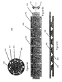
Recently a new class of bearing has been introduced which replaces the earlier roller technology with engineered materials such as ceramic and diamond. These bearings are designed to run against each other for long periods of time in harsh environments. FIG. 1 is a view of a radial bearing assembly 10 with engineered materials. The radial bearing assembly 10 includes an inner race 20 and an outer race 30 that are lined with one row of manufactured diamond buttons 25. When the inner race 20 is placed within the outer race 30 the manufactured diamond buttons 25 run against each other. As shown, the manufactured diamond buttons 25 on the inner race 20 and the outer race 30 are the same size (e.g., diameter). Although the manufactured diamond buttons 25 are specifically chosen to minimize friction, they still have friction which is a function of the applied load and, for this reason, are not applicable in all applications.
This invention generally relates to the suspension of rotating structures. In one aspect, a suspension system for use with rotating machinery is provided. The suspension system includes a first suspension assembly disposed between an inner structure and an outer structure of the rotating machinery for providing axial support. The first suspension assembly comprises an array of magnets. The suspension system further includes a second suspension assembly disposed between the structures for providing radial support. The second suspension assembly comprises at least one bearing member disposed between an inner portion and an outer portion.
In another aspect, a method of supporting an inner structure and an outer structure of rotating machinery is provided. The outer structure is configured to rotate relative to the inner structure. The method includes the step of providing a first suspension assembly between the inner structure and the outer structure for axially supporting the structures. The first suspension assembly comprises an array of magnets. The method further includes the step of providing a second suspension assembly for radially supporting the structures. The second suspension assembly comprises a bearing member.
In yet a further aspect, a rotating assembly is provided. The rotating assembly includes an inner structure and an outer structure, wherein the outer structure rotates relative to the inner structure. The rotating assembly further includes a first suspension assembly comprising an array of magnets for providing axial support to the structures. Additionally, the rotating assembly includes a second suspension assembly comprising an outer portion, an inner portion and at least one bearing member for providing radial support to the structures.
So that the manner in which the above recited features of the present invention can be understood in detail, a more particular description of the invention, briefly summarized above, may be had by reference to embodiments, some of which are illustrated in the appended drawings. It is to be noted, however, that the appended drawings illustrate only typical embodiments of this invention and are therefore not to be considered limiting of its scope, for the invention may admit to other equally effective embodiments.
This present invention generally relates to a method of suspension of rotating structures utilizing both engineered materials and magnetic material to optimize the system. Engineered materials are used in the radial direction where lateral forces are minimum, providing low friction losses, and magnetic material is used to create the axial suspension member where loads are high and variable, resulting in no friction contribution to the axial system. The present invention will be described herein in relation to rotating machinery, such as turbines, generators or any rotating shaft systems. It is to be understood, however, that the suspension assembly may also be used for other types of applications without departing from principles of the present invention. To better understand the novelty of the suspension assembly of the present invention and the methods of use thereof, reference is hereafter made to the accompanying drawings.
The axial bearing assembly 110 includes an array of magnet members comprising a first magnet member 140, a second magnet member 145, a third magnet member 150 and a fourth magnet member 155. The first magnet member 140 and the third magnet member 150 are attached to the inner structure 135, and the second magnet member 145 and fourth magnet member 155 are attached to the outer structure 130. In an alternative embodiment, the first magnet member 140 and the third magnet member 150 are attached to the outer structure 130, and the second magnet member 145 and fourth magnet member 155 are attached to the inner structure 135. The magnet members 140, 145, 150, 155 are shown as rings with a rectangular cross-section. It should be understood, however, that the magnet members 140, 145, 150, 155 may have any geometrical shape and cross-section, without departing from principles of the present invention. The present invention depicts the use of permanent magnets, however the present invention can also use electromagnets or a combination of permanent and electromagnets. The combination of electromagnets allows for controlled axial positioning with variable loading.
Each magnet member 140, 145, 150, 155 in the axial bearing assembly 110 includes a north magnetic pole (N) and a south magnetic pole (S). The magnet members may be arranged such that the magnetic poles for adjacent magnet members are the same. For instance, the south magnetic pole of the first magnet member 140 is facing the south magnetic pole of the second magnet member 145, and as such a repulsive force is generated between the first and second magnet members 140, 145. A similar arrangement may be established between the other magnet members such that the magnet members may be effectively held in balance between the repulsive forces of the other magnet members. As a result, the magnet members are arranged such that the outer structure 130 is automatically centralized relative to the inner structure 135. However, upon application of an axial force that is greater than the repulsive forces of the magnet members, the structures 130, 135 will move in an axial direction relative to each other (see arrow 105 or arrow 115). The axial force may be generated by fluid flow through the hybrid suspension system 100 or any other means.
The array of magnet members in the axial bearing assembly 110 may be arranged in other configurations. For example, the magnet members may be selected and arranged such that the outer structure 130 requires an axial load to be centralized relative to the inner structure 135. In another example, the magnet members may be selected and arranged such that the outer structure 130 is automatically offset relative to the inner structure 135. In other words, magnetic directions, strength and face-to-face spacing would be chosen to yield the desired response of the outer structure 130. An example of an axial magnetic suspension is described in U.S. patent application Ser. No. 13/163,136 filed on Jun. 17, 2011, which is incorporated herein by reference.
As shown in FIG. 2 , the radial bearing assembly 120 includes an inner portion 170 and an outer portion 180 having a plurality of bearing members 175. In the embodiment shown in FIG. 2 , the inner portion 170 and the bearing members 175 are made from engineered materials, such as ceramic or diamond. The inner portion 170 is attached to the inner structure 135, and the outer portion 180 is attached to the outer structure 130. As described herein, the radial bearing assembly 120 is configured to maintain contact between the bearing members 175 and the inner portion 170 even as the outer structure 130 and the inner structure 135 move axially relative to each other (see arrow 105 or arrow 115).
To illustrate the function of the radial bearing assembly 30, the inner portion 305 and the outer portion 325 have been flattened in FIGS. 5 b-5 c. Under no axial load, the inner portion 305 would be positioned as shown in FIG. 5 b, riding over the continuous outer portion 325. As axial load is applied to the system, the inner portion 305 will still be riding over the continuous outer portion 325. In a similar manner as the other embodiments, the radial bearing assembly 300 allows continuous radial support throughout the range of axial motion allowed between the inner portion 305 and the outer portion 325.
As shown in FIG. 9 , the outer structure 130 has moved in an axial direction illustrated by arrow 105 which causes the inner portion 170 of the radial bearing assembly 120 to move relative to the outer portion 180. The reason the outer structure 130 has moved in the axial direction illustrated by arrow 105 is because the magnetic directions, strength and face-to-face spacing of the magnet members 140, 145, 150, 155 in the axial bearing assembly 110 have been selected and arranged such that the outer structure 130 is automatically offset relative to the inner structure 135 when the rotating assembly 400 is in the off position (e.g., without fluid flow).
As shown in FIG. 10 , fluid flow 425 is applied to the rotating assembly 400, which places the electric generator in the on-position. As the fluid flow 425 impinges on the plurality of vanes 415, the outer structure 130 rotates relative to the inner structure 135. As the outer structure 130 rotates, field magnets 410 alternately pass coils 405, thus generating an electric current in the coils, and such current is then drawn off for other useful purposes. This same fluid flow 425 applies a force to the outer structure 130, pushing it in the axial direction indicated by arrow 115. The axial bearings 110 adjust their balance position, shifting the operating point on the radial bearings 120 to the direction indicated by arrow 115. In FIG. 10 , the radial bearings 120 are shown in their loaded position. In this manner the suspension system 100 can maintain the rotating assembly 400 through a wide range of variable flow conditions. To allow for the motion, the coils 405 in the rotating assembly 400 may be designed to be larger than the field magnets 410 to prevent any loss of electrical efficiency in the rotating assembly 400.
As with any magnetic bearing system there is a potential for axial oscillation and resonance. In the case illustrated in FIGS. 9 and 10 , this instability can be managed by regulating the rate at which the fluid can leave the interstitial space between the inner structure 135 and the outer structure 130, by managing the size and the spacing of the gaps 365 between the bearing members 360 and/or the grooves 380 in the outer portion 375 (see FIG. 6 a). For example, enlarging the widths of the gaps 365 and/or grooves 380 (or increasing the number of gaps 365 and/or grooves 380) fluid will flow more freely through the interstitial space between the inner structure 135 and the outer structure 130 which results in a decrease of damping of the axial oscillation and resonance of the axial bearing assembly 110. In contrast, decreasing the widths of the gaps 365 and/or grooves 380 (or decreasing the number of gaps 365 and/or grooves 380) there will be less fluid flow through the interstitial space between the inner structure 135 and the outer structure 130 which results in an increase of damping of the axial oscillation and resonance of the axial bearing assembly 110. In this manner, the axial oscillation and resonance of the magnetic axial bearing assembly 110 can be managed accordingly.
In the present examples, the outer structure 130 is designated as the rotating unit. In other embodiments, the outer structure 130 is fixed, allowing the inner structure 135 to rotate and placing the driving vanes on the inside of the inner structure 135.
There are numerous applications which can be attached to the connecting structures 130, 135 between the bearing structures 110, 120, including various sensor means. In an alternate embodiment, the suspension system 100 could also be used for linear axial support of a non-rotating structure.
In one aspect, a hybrid suspension system is provided. The hybrid suspension system includes a magnetic axial suspension, a radial suspension of engineered materials and interconnection structure allowing for useful work. In one embodiment, the radial suspension is diamond-on-diamond inserts. In another embodiment, the radial suspension consists of inserts running on a continuous race of hardened material. The continuous race is grooved to allow fluid to pass through the radial suspension. The continuous race has grooves machined at an angle to the axis to allow fluid pressure to alter the operating functionality. In a further embodiment, the radial suspension is diamond on silicon or tungsten carbide. In another embodiment, the radial suspension member has races of different widths allowing for motion in the axial direction without loss of function. In a further embodiment, fluid pumping ramps are used to maintain fluid on the bearing faces of the radial suspension. In another embodiment, the useful work is the generation of electricity. In a further embodiment, the useful work is a sensor means. In an additional embodiment, the application is linear axial support. In another embodiment, the application is support of rotating structures. In a further embodiment, the axial instability or oscillation is managed by regulating the flow of fluid in the suspension system.
While the foregoing is directed to embodiments of the present invention, other and further embodiments of the invention may be devised without departing from the basic scope thereof, and the scope thereof is determined by the claims that follow.
Claims (18)
1. A suspension system for use with rotating machinery, the system comprising:
a first suspension assembly disposed between an inner structure and an outer structure of the rotating machinery for providing axial support, the first suspension assembly comprising an array of magnets; and
a second suspension assembly disposed between the structures for providing radial support, the second suspension assembly comprising an inner portion in contact with the inner structure, an outer portion in contact with the outer structure, and at least one ceramic, diamond, or other non-metallic bearing member disposed between the inner portion and the outer portion, wherein the outer portion moves between a first axial position and a second axial position relative to the inner portion in response to receiving an axial load, wherein the inner portion includes a plurality of bearing members aligned in a row and the outer portion comprises a continuous piece of hardened material, wherein the outer portion includes a plurality of fluid pathways configured to supply fluid to the plurality of bearing members, and wherein the fluid pathways are grooves formed in an inner surface of the continuous piece of hardened material.
2. The suspension system of claim 1 , wherein the array of magnets causes the outer structure to move axially relative to the inner structure, thereby causing the outer portion of the second bearing member to move between the first axial position and the second axial position relative to the inner portion, and wherein the at least one bearing member is made from ceramic.
3. The suspension system of claim 2 , wherein the second suspension assembly allows continuous radial support throughout the range of axial motion allowed between the inner portion and the outer portion.
4. The suspension system of claim 1 , wherein the at least one bearing member is attached to the outer portion.
5. The suspension system of claim 1 , wherein the inner portion includes a plurality of bearing members having a circular shape with a first diameter and the outer portion includes a plurality of bearing members having a circular shape with a second larger diameter.
6. The suspension system of claim 5 , wherein the plurality of bearing members on the outer portion are aligned in a row along an inner circumference of the outer portion and the plurality of bearing members on the inner portion are aligned is a first row and a second row along an outer circumference of the inner portion.
7. The suspension system of claim 1 , wherein the outer portion includes a plurality of bearing members having circular shape and the inner portion comprises a plurality of block members.
8. The suspension system of claim 1 , wherein a width of each groove and spacing between each pair of bearing members is selected to control the axial oscillation of the first suspension assembly.
9. The suspension system of claim 1 , wherein the grooves are disposed at an angle relative to a longitudinal axis of the second suspension assembly.
10. The suspension system of claim 9 , wherein the grooves are configured to allow fluid energy to be converted into a rotational force.
11. A method of supporting an inner structure and an outer structure of rotating machinery, the outer structure being configured to rotate relative to the inner structure, the method comprising:
providing a first suspension assembly between the inner structure and the outer structure for axially supporting the structures, the first suspension assembly comprising an array of magnets; and
providing a second suspension assembly for radially supporting the structures, the second suspension assembly comprising an inner portion in contact with the inner structure, an outer portion in contact with the outer structure, and a ceramic, diamond, or other non-metallic bearing member, wherein the outer portion moves between a first axial position and a second axial position relative to the inner portion in response to receiving an axial load, wherein the inner portion includes a plurality of bearing members aligned in a row and the outer portion comprises a continuous piece of hardened material, wherein the outer portion includes a plurality of fluid pathways configured to supply fluid to the plurality of bearing members, and wherein the fluid pathways are grooves formed in an inner surface of the continuous piece of hardened material.
12. The method of claim 11 , wherein the array of magnets are configured to move the outer structure relative to the inner structure in a first direction to the first axial position.
13. The method of claim 12 , wherein a fluid pressure applied to the outer structure causes the outer structure to move relative to the inner structure in a second opposite direction to a second axial position.
14. The method of claim 13 , wherein the second suspension assembly is configured to provide radial support to the outer structure in the first axial position and the second axial position, and wherein the at least one bearing member is made from diamond.
15. A rotating assembly comprising:
an inner structure and an outer structure, wherein the outer structure rotates relative to the inner structure;
a first suspension assembly comprising an array of magnets for providing axial support to the structures; and
a second suspension assembly comprising an outer portion, an inner portion and at least one ceramic, diamond, or other non-metallic bearing member for providing radial support to the structures, wherein the outer portion moves between a first axial position and a second axial position relative to the inner portion in response to receiving an axial load, wherein the inner portion includes a plurality of bearing members aligned in a row and the outer portion comprises a continuous piece of hardened material, wherein the outer portion includes a plurality of fluid pathways configured to supply fluid to the plurality of bearing members, and wherein the fluid pathways are grooves formed in an inner surface of the continuous piece of hardened material.
16. The rotating assembly of claim 15 , further comprising a plurality of coils and field magnets arrayed around the inner and outer structures for generating electric current as the outer structure rotates relative to the inner structure.
17. The rotating assembly of claim 15 , further comprising a plurality of vanes disposed around the outer structure that are configured to cause the outer structure to rotate when fluid flow impinges on the plurality of vanes.
18. The rotating assembly of claim 15 , wherein the outer portion includes a first array of bearings and the inner portion includes a second array of bearings.
Priority Applications (4)
| Application Number | Priority Date | Filing Date | Title |
|---|---|---|---|
| US13/185,418 US8941278B2 (en) | 2010-07-19 | 2011-07-18 | Method and apparatus for hybrid suspension system |
| PCT/US2011/044575 WO2012012459A1 (en) | 2010-07-19 | 2011-07-19 | Method and apparatus for hybrid suspension system |
| NO20130127A NO20130127A1 (en) | 2010-07-19 | 2013-01-24 | Method and apparatus for hybrid suspension system |
| US14/605,932 US9765815B2 (en) | 2010-07-19 | 2015-01-26 | Method and apparatus for hybrid suspension system |
Applications Claiming Priority (2)
| Application Number | Priority Date | Filing Date | Title |
|---|---|---|---|
| US36569110P | 2010-07-19 | 2010-07-19 | |
| US13/185,418 US8941278B2 (en) | 2010-07-19 | 2011-07-18 | Method and apparatus for hybrid suspension system |
Related Child Applications (1)
| Application Number | Title | Priority Date | Filing Date |
|---|---|---|---|
| US14/605,932 Continuation US9765815B2 (en) | 2010-07-19 | 2015-01-26 | Method and apparatus for hybrid suspension system |
Publications (2)
| Publication Number | Publication Date |
|---|---|
| US20120013215A1 US20120013215A1 (en) | 2012-01-19 |
| US8941278B2 true US8941278B2 (en) | 2015-01-27 |
Family
ID=44511502
Family Applications (2)
| Application Number | Title | Priority Date | Filing Date |
|---|---|---|---|
| US13/185,418 Expired - Fee Related US8941278B2 (en) | 2010-07-19 | 2011-07-18 | Method and apparatus for hybrid suspension system |
| US14/605,932 Expired - Fee Related US9765815B2 (en) | 2010-07-19 | 2015-01-26 | Method and apparatus for hybrid suspension system |
Family Applications After (1)
| Application Number | Title | Priority Date | Filing Date |
|---|---|---|---|
| US14/605,932 Expired - Fee Related US9765815B2 (en) | 2010-07-19 | 2015-01-26 | Method and apparatus for hybrid suspension system |
Country Status (3)
| Country | Link |
|---|---|
| US (2) | US8941278B2 (en) |
| NO (1) | NO20130127A1 (en) |
| WO (1) | WO2012012459A1 (en) |
Cited By (4)
| Publication number | Priority date | Publication date | Assignee | Title |
|---|---|---|---|---|
| US20150008676A1 (en) * | 2012-02-06 | 2015-01-08 | Ge Energy Power Conversion Technology Limited | Marine turbine comprising a stator, a rotor, a first magnetic bearing supporting the rotor and a second support bearing with rolling element (s) |
| US20150130313A1 (en) * | 2010-07-19 | 2015-05-14 | Peter S. Aronstam | Method and Apparatus For Hybrid Suspension System |
| US20180100543A1 (en) * | 2016-10-11 | 2018-04-12 | Ge Oil & Gas Esp, Inc. | Permanent Magnet Thrust Bearing |
| US10533393B2 (en) | 2016-12-06 | 2020-01-14 | Saudi Arabian Oil Company | Modular thru-tubing subsurface completion unit |
Families Citing this family (5)
| Publication number | Priority date | Publication date | Assignee | Title |
|---|---|---|---|---|
| US8317651B2 (en) | 2008-05-07 | 2012-11-27 | Fallbrook Intellectual Property Company Llc | Assemblies and methods for clamping force generation |
| WO2014020593A1 (en) | 2012-07-30 | 2014-02-06 | Chakratec Ltd. | Magnetically coupled flywheel |
| CN106763183A (en) * | 2017-01-12 | 2017-05-31 | 陈科枫 | Permanent-magnet suspension bearing based on gyroscopic effect |
| US11532416B1 (en) * | 2021-09-13 | 2022-12-20 | Te-Wei Liu | Magnetic levitation device |
| CN115045914B (en) * | 2022-06-30 | 2023-10-31 | 中国铁建重工集团股份有限公司 | Non-contact slewing bearing |
Citations (22)
| Publication number | Priority date | Publication date | Assignee | Title |
|---|---|---|---|---|
| US3221389A (en) * | 1964-09-22 | 1965-12-07 | Ind Tectonics Inc | Textile spindle |
| US4065234A (en) * | 1975-12-22 | 1977-12-27 | Nihon Kagaku Kizai Kabushiki Kaisha | Magnetically driven rotary pumps |
| US4756631A (en) | 1987-07-24 | 1988-07-12 | Smith International, Inc. | Diamond bearing for high-speed drag bits |
| US5559381A (en) * | 1993-11-08 | 1996-09-24 | Rosen Motors, L.P. | Flywheel support system for mobile energy storage |
| US5587617A (en) * | 1994-08-12 | 1996-12-24 | Seagate Technology, Inc. | Integrated passive magnetic bearing system and spindle magnet for use in an axial magnet spindle motor |
| US5627421A (en) * | 1994-10-28 | 1997-05-06 | Barber-Colman Company | High efficiency drive circuit for an active magnetic bearing system |
| US5834870A (en) * | 1994-04-28 | 1998-11-10 | Hitachi, Ltd. | Oil impregnated porous bearing units and motors provided with same |
| US5856719A (en) * | 1994-12-12 | 1999-01-05 | De Armas; Jorge | Electromagnetic-coupled/levitated apparatus and method for rotating equipment |
| US5867979A (en) * | 1996-03-28 | 1999-02-09 | Rolls-Royce Plc | Gas turbine engine system |
| US6215218B1 (en) * | 1998-04-09 | 2001-04-10 | Koyo Seiko Co., Ltd. | Control magnetic bearing |
| US6218751B1 (en) * | 1997-05-26 | 2001-04-17 | Global Hemostasis Institute Mgr | Bearing device |
| US20010048257A1 (en) * | 1997-04-28 | 2001-12-06 | Ntn Corporation. | Combined externally pressurized gas-magnetic bearing assembly and spindle device utilizing the same |
| US6340854B1 (en) * | 2000-03-27 | 2002-01-22 | Samsung-Electro-Mechanics Co., Ltd. | Scanner motor |
| US6420810B1 (en) * | 2000-03-29 | 2002-07-16 | Samsung Electro-Mechanics Co., Ltd. | Non-contact driving motor |
| US20030015930A1 (en) * | 2001-07-23 | 2003-01-23 | Yoshikazu Ichiyama | Motor having single cone air dynamic bearing balanced with shaft end magnetic attraction |
| US20030155830A1 (en) * | 2000-05-06 | 2003-08-21 | Christian Beyer | Magnetic bearing with damping |
| US6710489B1 (en) * | 2001-08-30 | 2004-03-23 | Indigo Energy, Inc. | Axially free flywheel system |
| US20040190804A1 (en) * | 2003-03-26 | 2004-09-30 | Baker Hughes Incorporated | Diamond bearing with cooling/lubrication channels |
| EP1770284A2 (en) | 2005-09-29 | 2007-04-04 | JTEKT Corporation | Fuell-cell compressed-air supplying device |
| US20070081749A1 (en) | 2005-10-11 | 2007-04-12 | Sexton Timothy N | Bearing apparatuses, systems including same, and related methods |
| DE202010002867U1 (en) | 2009-02-27 | 2010-07-15 | U.S. Synthetic Corp., Orem | Storage facilities and installations containing them |
| US20110291507A1 (en) * | 2010-06-01 | 2011-12-01 | Post Richard F | Magnetic bearing element with adjustable stiffness |
Family Cites Families (1)
| Publication number | Priority date | Publication date | Assignee | Title |
|---|---|---|---|---|
| US8941278B2 (en) * | 2010-07-19 | 2015-01-27 | Peter S. Aronstam | Method and apparatus for hybrid suspension system |
-
2011
- 2011-07-18 US US13/185,418 patent/US8941278B2/en not_active Expired - Fee Related
- 2011-07-19 WO PCT/US2011/044575 patent/WO2012012459A1/en active Application Filing
-
2013
- 2013-01-24 NO NO20130127A patent/NO20130127A1/en not_active Application Discontinuation
-
2015
- 2015-01-26 US US14/605,932 patent/US9765815B2/en not_active Expired - Fee Related
Patent Citations (22)
| Publication number | Priority date | Publication date | Assignee | Title |
|---|---|---|---|---|
| US3221389A (en) * | 1964-09-22 | 1965-12-07 | Ind Tectonics Inc | Textile spindle |
| US4065234A (en) * | 1975-12-22 | 1977-12-27 | Nihon Kagaku Kizai Kabushiki Kaisha | Magnetically driven rotary pumps |
| US4756631A (en) | 1987-07-24 | 1988-07-12 | Smith International, Inc. | Diamond bearing for high-speed drag bits |
| US5559381A (en) * | 1993-11-08 | 1996-09-24 | Rosen Motors, L.P. | Flywheel support system for mobile energy storage |
| US5834870A (en) * | 1994-04-28 | 1998-11-10 | Hitachi, Ltd. | Oil impregnated porous bearing units and motors provided with same |
| US5587617A (en) * | 1994-08-12 | 1996-12-24 | Seagate Technology, Inc. | Integrated passive magnetic bearing system and spindle magnet for use in an axial magnet spindle motor |
| US5627421A (en) * | 1994-10-28 | 1997-05-06 | Barber-Colman Company | High efficiency drive circuit for an active magnetic bearing system |
| US5856719A (en) * | 1994-12-12 | 1999-01-05 | De Armas; Jorge | Electromagnetic-coupled/levitated apparatus and method for rotating equipment |
| US5867979A (en) * | 1996-03-28 | 1999-02-09 | Rolls-Royce Plc | Gas turbine engine system |
| US20010048257A1 (en) * | 1997-04-28 | 2001-12-06 | Ntn Corporation. | Combined externally pressurized gas-magnetic bearing assembly and spindle device utilizing the same |
| US6218751B1 (en) * | 1997-05-26 | 2001-04-17 | Global Hemostasis Institute Mgr | Bearing device |
| US6215218B1 (en) * | 1998-04-09 | 2001-04-10 | Koyo Seiko Co., Ltd. | Control magnetic bearing |
| US6340854B1 (en) * | 2000-03-27 | 2002-01-22 | Samsung-Electro-Mechanics Co., Ltd. | Scanner motor |
| US6420810B1 (en) * | 2000-03-29 | 2002-07-16 | Samsung Electro-Mechanics Co., Ltd. | Non-contact driving motor |
| US20030155830A1 (en) * | 2000-05-06 | 2003-08-21 | Christian Beyer | Magnetic bearing with damping |
| US20030015930A1 (en) * | 2001-07-23 | 2003-01-23 | Yoshikazu Ichiyama | Motor having single cone air dynamic bearing balanced with shaft end magnetic attraction |
| US6710489B1 (en) * | 2001-08-30 | 2004-03-23 | Indigo Energy, Inc. | Axially free flywheel system |
| US20040190804A1 (en) * | 2003-03-26 | 2004-09-30 | Baker Hughes Incorporated | Diamond bearing with cooling/lubrication channels |
| EP1770284A2 (en) | 2005-09-29 | 2007-04-04 | JTEKT Corporation | Fuell-cell compressed-air supplying device |
| US20070081749A1 (en) | 2005-10-11 | 2007-04-12 | Sexton Timothy N | Bearing apparatuses, systems including same, and related methods |
| DE202010002867U1 (en) | 2009-02-27 | 2010-07-15 | U.S. Synthetic Corp., Orem | Storage facilities and installations containing them |
| US20110291507A1 (en) * | 2010-06-01 | 2011-12-01 | Post Richard F | Magnetic bearing element with adjustable stiffness |
Non-Patent Citations (1)
| Title |
|---|
| PCT/US2011/044575 International Search Report (Oct. 7, 2011). |
Cited By (17)
| Publication number | Priority date | Publication date | Assignee | Title |
|---|---|---|---|---|
| US20150130313A1 (en) * | 2010-07-19 | 2015-05-14 | Peter S. Aronstam | Method and Apparatus For Hybrid Suspension System |
| US9765815B2 (en) * | 2010-07-19 | 2017-09-19 | Peter S. Aronstam | Method and apparatus for hybrid suspension system |
| US20150008676A1 (en) * | 2012-02-06 | 2015-01-08 | Ge Energy Power Conversion Technology Limited | Marine turbine comprising a stator, a rotor, a first magnetic bearing supporting the rotor and a second support bearing with rolling element (s) |
| US9611831B2 (en) * | 2012-02-06 | 2017-04-04 | Ge Energy Power Conversion Technology Ltd | Marine turbine comprising a stator, a rotor, a first magnetic bearing supporting the rotor and a second support bearing with rolling element(s) |
| US20180100543A1 (en) * | 2016-10-11 | 2018-04-12 | Ge Oil & Gas Esp, Inc. | Permanent Magnet Thrust Bearing |
| US10598221B2 (en) * | 2016-10-11 | 2020-03-24 | Baker Hughes Oilfield Operations, Llc | Permanent magnet thrust bearing |
| US10584556B2 (en) | 2016-12-06 | 2020-03-10 | Saudi Arabian Oil Company | Thru-tubing subsurface completion unit employing detachable anchoring seals |
| US10570696B2 (en) | 2016-12-06 | 2020-02-25 | Saudi Arabian Oil Company | Thru-tubing retrievable intelligent completion system |
| US10563478B2 (en) | 2016-12-06 | 2020-02-18 | Saudi Arabian Oil Company | Thru-tubing retrievable subsurface completion system |
| US10533393B2 (en) | 2016-12-06 | 2020-01-14 | Saudi Arabian Oil Company | Modular thru-tubing subsurface completion unit |
| US10641060B2 (en) | 2016-12-06 | 2020-05-05 | Saudi Arabian Oil Company | Thru-tubing retrievable subsurface completion system |
| US10655429B2 (en) | 2016-12-06 | 2020-05-19 | Saudi Arabian Oil Company | Thru-tubing retrievable intelligent completion system |
| US10724329B2 (en) | 2016-12-06 | 2020-07-28 | Saudi Arabian Oil Company | Thru-tubing retrievable subsurface completion system |
| US10781660B2 (en) | 2016-12-06 | 2020-09-22 | Saudi Arabian Oil Company | Thru-tubing retrievable intelligent completion system |
| US10907442B2 (en) | 2016-12-06 | 2021-02-02 | Saudi Arabian Oil Company | Thru-tubing retrievable subsurface completion system |
| US11078751B2 (en) | 2016-12-06 | 2021-08-03 | Saudi Arabian Oil Company | Thru-tubing retrievable intelligent completion system |
| US11156059B2 (en) | 2016-12-06 | 2021-10-26 | Saudi Arabian Oil Company | Thru-tubing subsurface completion unit employing detachable anchoring seals |
Also Published As
| Publication number | Publication date |
|---|---|
| US9765815B2 (en) | 2017-09-19 |
| US20120013215A1 (en) | 2012-01-19 |
| US20150130313A1 (en) | 2015-05-14 |
| NO20130127A1 (en) | 2013-04-19 |
| WO2012012459A1 (en) | 2012-01-26 |
Similar Documents
| Publication | Publication Date | Title |
|---|---|---|
| US9765815B2 (en) | Method and apparatus for hybrid suspension system | |
| US8803392B2 (en) | Axial magnetic suspension | |
| US8157539B2 (en) | Artificial heart pump | |
| CN108591257B (en) | Permanent magnet biased axial magnetic suspension bearing with radial passive suspension force | |
| US7876010B2 (en) | Passive magnetic bearing configurations | |
| KR20190005161A (en) | An electric machine including an axial thrust bearing | |
| JP2015090218A (en) | Bearing structure for fluid machine device | |
| CN101515774B (en) | High-temperature superconducting permanent magnetic hybrid magnetic suspension variable-frequency motor | |
| JP3057047B2 (en) | Magnetic suspension | |
| US5588754A (en) | Backup bearings for extreme speed touch down applications | |
| WO2006022554A1 (en) | Bearing with permanent magnetic elements | |
| KR101552350B1 (en) | Thrust Magnetic Bearing for Bias Compensation | |
| US10584765B2 (en) | Dynamic force generator comprising at least two unbalanced masses and actuator comprising said generators | |
| CN110748562A (en) | Surrounding permanent magnet biased axial-radial magnetic suspension bearing | |
| CN110332235B (en) | Passive permanent magnet repulsion type magnetic bearing structure | |
| WO2014007851A1 (en) | Active magnetic bearing assembly and arrangement of magnets therefor | |
| KR102208324B1 (en) | Axial gap electromechanical with permanent magnets arranged between the posts | |
| CA2940967C (en) | Rotary machine having magnetic and mechanical bearings | |
| CN102588434A (en) | Permanent magnet suspension bearing and installation structure thereof | |
| TWI484106B (en) | Hybrid type of magnet bearing system | |
| WO2001084693A1 (en) | Full levitation bearing system with improved passive radial magnetic bearings | |
| CN110300859B (en) | Magnetic bearing and method for operating a magnetic bearing | |
| EP3825563B1 (en) | Magnetic bearing | |
| WO2018150192A1 (en) | Electric motor | |
| WO2012154066A1 (en) | Magnetic bearing and magnetic bearing mode of action |
Legal Events
| Date | Code | Title | Description |
|---|---|---|---|
| FEPP | Fee payment procedure |
Free format text: MAINTENANCE FEE REMINDER MAILED (ORIGINAL EVENT CODE: REM.); ENTITY STATUS OF PATENT OWNER: SMALL ENTITY |
|
| LAPS | Lapse for failure to pay maintenance fees |
Free format text: PATENT EXPIRED FOR FAILURE TO PAY MAINTENANCE FEES (ORIGINAL EVENT CODE: EXP.); ENTITY STATUS OF PATENT OWNER: SMALL ENTITY |
|
| STCH | Information on status: patent discontinuation |
Free format text: PATENT EXPIRED DUE TO NONPAYMENT OF MAINTENANCE FEES UNDER 37 CFR 1.362 |
|
| FP | Lapsed due to failure to pay maintenance fee |
Effective date: 20190127 |