US8942778B2 - Analyte monitoring sensor system for monitoring a constituent in body tissue - Google Patents

Analyte monitoring sensor system for monitoring a constituent in body tissue Download PDF

Info

Publication number
US8942778B2
US8942778B2 US13/110,335 US201113110335A US8942778B2 US 8942778 B2 US8942778 B2 US 8942778B2 US 201113110335 A US201113110335 A US 201113110335A US 8942778 B2 US8942778 B2 US 8942778B2
Authority
US
United States
Prior art keywords
sensor
sensor system
body tissue
fluid channel
support
Prior art date
Legal status (The legal status is an assumption and is not a legal conclusion. Google has not performed a legal analysis and makes no representation as to the accuracy of the status listed.)
Active, expires
Application number
US13/110,335
Other versions
US20110218490A1 (en
Inventor
Gregor Ocvirk
Helmut Rinne
Arnulf Staib
Current Assignee (The listed assignees may be inaccurate. Google has not performed a legal analysis and makes no representation or warranty as to the accuracy of the list.)
Roche Diabetes Care Inc
Original Assignee
Roche Diagnostics Operations Inc
Priority date (The priority date is an assumption and is not a legal conclusion. Google has not performed a legal analysis and makes no representation as to the accuracy of the date listed.)
Filing date
Publication date
Application filed by Roche Diagnostics Operations Inc filed Critical Roche Diagnostics Operations Inc
Priority to US13/110,335 priority Critical patent/US8942778B2/en
Assigned to ROCHE DIAGNOSTICS GMBH reassignment ROCHE DIAGNOSTICS GMBH ASSIGNMENT OF ASSIGNORS INTEREST (SEE DOCUMENT FOR DETAILS). Assignors: RINNE, HELMUT, OCVIRK, GREGOR, STAIB, ARNULF
Assigned to ROCHE DIAGNOSTICS OPERATIONS, INC. reassignment ROCHE DIAGNOSTICS OPERATIONS, INC. ASSIGNMENT OF ASSIGNORS INTEREST (SEE DOCUMENT FOR DETAILS). Assignors: ROCHE DIAGNOSTICS GMBH
Publication of US20110218490A1 publication Critical patent/US20110218490A1/en
Application granted granted Critical
Publication of US8942778B2 publication Critical patent/US8942778B2/en
Assigned to ROCHE DIABETES CARE, INC. reassignment ROCHE DIABETES CARE, INC. ASSIGNMENT OF ASSIGNORS INTEREST (SEE DOCUMENT FOR DETAILS). Assignors: ROCHE DIAGNOSTICS OPERATIONS, INC.
Active legal-status Critical Current
Adjusted expiration legal-status Critical

Links

Images

Classifications

    • AHUMAN NECESSITIES
    • A61MEDICAL OR VETERINARY SCIENCE; HYGIENE
    • A61BDIAGNOSIS; SURGERY; IDENTIFICATION
    • A61B5/00Measuring for diagnostic purposes; Identification of persons
    • A61B5/145Measuring characteristics of blood in vivo, e.g. gas concentration, pH value; Measuring characteristics of body fluids or tissues, e.g. interstitial fluid, cerebral tissue
    • A61B5/1486Measuring characteristics of blood in vivo, e.g. gas concentration, pH value; Measuring characteristics of body fluids or tissues, e.g. interstitial fluid, cerebral tissue using enzyme electrodes, e.g. with immobilised oxidase
    • A61B5/14865Measuring characteristics of blood in vivo, e.g. gas concentration, pH value; Measuring characteristics of body fluids or tissues, e.g. interstitial fluid, cerebral tissue using enzyme electrodes, e.g. with immobilised oxidase invasive, e.g. introduced into the body by a catheter or needle or using implanted sensors
    • AHUMAN NECESSITIES
    • A61MEDICAL OR VETERINARY SCIENCE; HYGIENE
    • A61BDIAGNOSIS; SURGERY; IDENTIFICATION
    • A61B5/00Measuring for diagnostic purposes; Identification of persons
    • A61B5/145Measuring characteristics of blood in vivo, e.g. gas concentration, pH value; Measuring characteristics of body fluids or tissues, e.g. interstitial fluid, cerebral tissue
    • A61B5/14532Measuring characteristics of blood in vivo, e.g. gas concentration, pH value; Measuring characteristics of body fluids or tissues, e.g. interstitial fluid, cerebral tissue for measuring glucose, e.g. by tissue impedance measurement

Definitions

  • the invention generally relates to a sensor system.
  • a sensor for glucose monitoring In particular to a sensor for glucose monitoring.
  • the invention also also relates to an arrangement and a method for monitoring a constituent and in particular glucose in body tissue using a sensor system.
  • Body tissue consists of cells and a tissue structure in a liquid environment in which metabolic products are transported between the cells and the blood vessels.
  • glucose monitoring especially in the case of diabetic patients it is possible to insert a probe into tissue for long periods in order to continuously collect constituents from the tissue fluid by means of diffusion processes and to determine the glucose content in the tissue from the effusate. This can be closely correlated with the blood glucose content without requiring an invasive access to the blood circulation.
  • the construction is very complex and the system inserted into the body tissue is not realized in an integrated and miniaturized design.
  • there is a risk with rigid needle sensors that additional injuries to the surrounding tissue may occur while it remains in the body and as a result of which significant errors may occur in the determination of the analyte concentration.
  • the object of the invention is to avoid the disadvantages occurring in the prior art and to enable the determination of a constituent in the surrounding matrix and passage of a liquid in a simple manner using an implantable device and an appropriate method.
  • the invention is generally based on the idea of integrating a sensor and a separate liquid passage on a substrate. Accordingly, it is proposed according to the invention that the sensor is arranged on the support separately from the fluid channel for a direct contact with the body tissue. Information on a constituent can thus be obtained directly from the tissue outside of the liquid that is fed in and out. This enables an optimization of the response time and overall time behaviour of the system while simplifying the manufacture due to the integrated design. In addition, storage, transport and collection of perfusion fluids is also dispensed with allowing a substantial reduction in the size of the system especially for applications that can be carried on the body.
  • the senor In order to make a direct contact with the body tissue i.e. with the cells, the vessels and the supporting matrix, the sensor is located on a surface of the support that is in contact with the body tissue in the inserted state.
  • the sensor is designed to detect the constituent substantially independently of the amount of extracellular fluid that is present. Hence the sensor responds to an analyte without a measuring volume having to be previously completely filled with liquid at the local site of measurement.
  • the sensor is in contact with the body tissue at a distance from the opening of the fluid channel on the tissue side. This allows various applications to be achieved in a simple manner which require only one puncture site.
  • the sensor system provides a calibration device for the sensor to be located outside body tissue.
  • the calibration device can be loaded with interstitial fluid via the fluid channel, wherein the calibration device has a reference sensor for calibrating the output signals of the sensor.
  • a calibration solution can optionally also be delivered to the calibration device via the fluid channel.
  • the fluid channel is connected to a pump unit for removing interstitial fluid from the body tissue.
  • the fluid channel is connected to a metering unit for feeding a medication liquid and especially one which contains insulin into the body tissue.
  • the fluid channel is connected to a conveying device for feeding a calibration solution of known composition into the body tissue.
  • the senor For a direct acquisition of measured values, the sensor has an active sensor region that can be brought into contact or is in contact with the body tissue.
  • the sensor is designed to continuously detect glucose as the constituent in the interstitial fluid.
  • the sensor in a multielectrode design has several electrodes arranged on a surface of the support that engages with the body tissue.
  • the support consists of a flexible substrate where the fluid channel and sensor are integrated into the substrate.
  • the flexible and blunt-edged support can be inserted into the body tissue by means of an insertion aid.
  • the fluid channel has at least one opening on the tissue side, at least one opening located outside the body tissue and at least one flow path between the openings that is closed or half open on the longitudinal side and is in particular a capillary flow path.
  • the fluid channel is integrated into the optionally multi-part support by laser treatment, hot stamping or photolithography.
  • Another improvement is attained by the fluid channel having a flow cross-section of less than 1 mm 2 .
  • the fluid channel flows into the detection area of the sensor on a surface of the support carrying the sensor, or that the fluid channel flows into a part of the support that faces away from or is distant from the sensor which is outside of the detection area of the sensor.
  • At least two single sensors can be provided as a sensor at different distances from a tissue-side opening of the fluid channel.
  • the senor has a single sensor for an analyte and a single sensor for an active substance that can be passed into the body tissue through the fluid channel.
  • the invention also concerns an arrangement for monitoring a constituent and especially glucose in body tissue comprising one of the sensor systems described above.
  • the sensor system is coupled to a signal processing unit for the quantitative determination of the constituent.
  • the quantity of liquid which in particular contains insulin that is passed through the fluid channel can be controlled by a control or regulating device.
  • the object mentioned above is achieved by arranging the sensor on the support separately from the fluid channel and by bringing it into direct contact with the body tissue.
  • the present also provides to regulate or control the liquid transport through the fluid channel as a function of an output signal of the sensor.
  • FIG. 1 shows a block diagram of an arrangement for monitoring glucose in body tissue
  • FIG. 2 shows a sensor system arranged according to FIG. 1 in a top-view
  • FIGS. 3 to 5 show sections along the lines 3 - 3 , 4 - 4 and 5 - 5 of FIG. 2 .
  • the monitoring system shown in FIG. 1 comprises a sensor system 10 , a conveying unit 12 with a liquid reservoir 14 , a signal processing unit 16 with an alarm trigger 18 , a control unit 20 for the conveying unit 12 and a calibration device 22 .
  • the arrangement enables constituents (glucose) to be determined in the surrounding matrix by means of the subcutaneously implantable sensor system 10 and allows passage of a liquid.
  • the sensor system 10 has a support 24 , an electrochemical sensor 26 mounted thereon and an integrated fluid channel 28 .
  • the flexible support 24 is for example made from a flexible foil material as a substrate and at least a shaft region 30 thereof can be implanted into body tissue.
  • An insertion aid (not shown) is used for this purpose which creates the necessary tissue opening.
  • the support is made of an inflexible material in a needle-like design and can be directly inserted into the body tissue.
  • the sensor 26 comprises a working electrode 32 , a counter electrode 34 and a reference electrode 36 .
  • the electrodes are in an electrically conducting contact with associated contact tongues 40 via respective conducting paths 38 , said tongues being located on a connecting part 42 of the support 24 that is located outside the body tissue.
  • the working electrode 32 is characterized as an enzyme electrode in that an intermediate product is formed by the reaction of the analyte (glucose) with a specific enzyme and the intermediate product is converted electrochemically on the working electrode by applying a constant potential between the reference electrode and working electrode. As a result a measurement signal can be detected in a known manner which correlates with the glucose concentration.
  • the potential between the reference electrode and working electrode can be kept constant by means of the reference electrode 36 using a potentiostat to prevent the electrochemical conversion of interfering substances.
  • the working electrode 32 can be provided with additional layers which serve as a diffusion barrier layer for glucose, as a barrier layer for interfering substances and as a biocompatible layer facing the tissue.
  • the size of the counter electrode 34 is selected such that the current density and thus excess voltage is minimized.
  • the shape of the electrodes There are no constraints on the shape of the electrodes; rectangular or round electrode shapes are can be used. It is also possible that the electrodes intermesh. In each case the free surface of the electrodes forms an active sensor region 44 that can be brought into direct contact with the body tissue, said sensor area being arranged on the support 24 spatially separated from the fluid channel 28 . It is also conceivable that several single sensors also have common electrodes in the form of a multielectrode system.
  • a liquid can be removed from or supplied to the body tissue through the fluid channel 28 .
  • the fluid channel 28 has at least one opening 46 on the tissue side, at least one opening 48 located outside of the body tissue and at least one flow path 50 between the openings.
  • the side of the flow path 50 is closed and the flow path can have a capillary-active cross-section of for example less than 1 mm 2 . Hence the liquid volume contained in the fluid channel 28 can also be kept low.
  • the opening 46 on the tissue side should be designed such that no significant increase in the hydrodynamic resistance relative to the flow path 50 due to body reactions in this region is detectable during the implantation time.
  • the physical and chemical properties, the microstructure and the morphology of the surface should be selected such that protein and cell adsorption is kept small.
  • a low surface charge is particularly advantageous.
  • the support 24 can be composed of multiple layers and in particular consists of a base foil 52 , an insulating layer 54 and a cover layer 56 .
  • the flow path 50 or rather the liquid passage is produced by laser ablation, hot stamping or photolithography and is closed in a liquid-tight manner by the cover layer 56 with the exception of the openings 46 , 48 .
  • the subcutaneously implanted glucose sensor 26 is connected via the contact tongues 40 to the extracorporeal signal processing unit 16 in order to display a measuring result to the user that correlates with the glucose content of the interstitial fluid and thus also with the blood glucose and optionally to trigger an alarm via the alarm trigger 18 when it is outside the normoglycaemic range.
  • interstitial fluid can be removed or calibration solution can be supplied via the fluid channel 28 and the downstream conveying unit 12 such that their glucose content or constituent can be determined in parallel by means of the external calibration device 22 or the concentration is known.
  • the calibration device 22 has a reference sensor 58 to which the tissue fluid can be applied. Hence it is possible to automatically carry out a calibration of the output signal of the body sensor 26 that is processed in the signal processing unit 16 at specified time intervals.
  • a conveying unit 60 may be connected to the fluid channel 28 to feed a calibration solution into the body tissue or a metering unit 62 may be connected to the fluid channel 28 to administer a medication liquid which in particular contains insulin into the body tissue.
  • a metering unit 62 may be connected to the fluid channel 28 to administer a medication liquid which in particular contains insulin into the body tissue.
  • a closed control loop can be provided for the liquid transport.
  • the distance of the sensor 26 from the opening 46 of the fluid channel 28 on the tissue side can be varied depending on the composition of the delivered liquid. If a solution of a known analyte content is delivered, the distance should be as small as possible so that a direct change of the measured signal occurs after the liquid flows out from the opening 46 . If a solution of an active substance (insulin) is supplied which influences the analyte concentration (glucose) in the tissue, the distance is selected such that at the given pressure difference between the opening 46 and tissue environment, at the given colloid osmotic pressure, at the given time period of liquid supply and at the given diffusion coefficient of the analyte no measurable change in the analyte concentration of the body fluid occurs in the direct vicinity of the sensor.
  • an active substance insulin
  • Another embodiment which is not specifically shown comprises two single sensors for the analyte which are spaced apart, one of the single sensors being located nearer to the tissue-side opening 46 .
  • This allows a detection of two different subcutaneous sites which is advantageous due to the inhomogeneity of the subcutaneous tissue and of the respective tissue reaction.
  • solutions of active substances are delivered via the fluid channel 28
  • an interaction of the active substance with the surrounding tissue can be determined with the aid of one of the single sensors in order to detect a disease state or for therapeutic monitoring, while the delivery of the solution of active substance can be controlled by means of the other single sensor.
  • Using the said single sensors it is also possible to separately determine an analyte and an active substance fed in via the fluid channel 28 .
  • the analyte sensor should be at a greater distance from the opening 46 than the active substance sensor. In addition to determining the analyte concentration, this also enables the active substance to be determined in the surrounding tissue thus allowing a detection of a disease state and therapeutic monitoring.
  • first analyte sensor is at a greater distance from the opening 46 on the tissue side than the second analyte sensor and than the active substance sensor.
  • a tissue capsule forms around an object implanted in tissue in the process of wound healing.
  • the thickness of the fibrous tissue capsule depends on the size of the object itself. It may be assumed that the fibrous capsule represents a diffusion barrier for an implanted sensor.
  • the success of the measurement does not depend on the amount of interstitial fluid which is hardly present particularly in subcutaneous tissue. Hence the measurement is hardly affected by other influencing factors such as pressure, movement and position of the tissue, which influence the tissue content of interstitial fluid.
  • An insertion set that can be cost-effectively manufactured, that is miniaturized and thus causes minimum damage to the body tissue is created for the improved use of flexible thin layer sensors for measuring constituents in a body tissue.
  • it is not necessary to pass through a dialysis fluid because the implanted sensor is directly contacted with the tissue i.e. with the cells, the vessels and the supporting matrix. This makes measurement in interstitial fluid obsolete.
  • the term “substantially” is utilized herein to represent the inherent degree of uncertainty that may be attributed to any quantitative comparison, value, measurement, or other representation.
  • the term “substantially” is also utilized herein to represent the degree by which a quantitative representation may vary from a stated reference without resulting in a change in the basic function of the subject matter at issue.

Abstract

The invention generally relates to a sensor system. In particular to a sensor for glucose monitoring. The invention also also relates to an arrangement and a method for monitoring a constituent and in particular glucose in body tissue using a sensor system.

Description

REFERENCE TO RELATED APPLICATIONS
This application is a continuation of prior Application Ser. No. 11/425,020, filed Jun. 19, 2006 now U.S. Pat. No. 7,967,752, and claims priority to European Patent Application No. 05 013 063.2, filed Jun. 17, 2005, both of which are hereby incorporated by reference in their entirety.
TECHNICAL FIELD
The invention generally relates to a sensor system. In particular to a sensor for glucose monitoring. The invention also also relates to an arrangement and a method for monitoring a constituent and in particular glucose in body tissue using a sensor system.
BACKGROUND
Body tissue consists of cells and a tissue structure in a liquid environment in which metabolic products are transported between the cells and the blood vessels. For glucose monitoring especially in the case of diabetic patients it is possible to insert a probe into tissue for long periods in order to continuously collect constituents from the tissue fluid by means of diffusion processes and to determine the glucose content in the tissue from the effusate. This can be closely correlated with the blood glucose content without requiring an invasive access to the blood circulation. At the same time it is possible to administer an insulin-containing medication solution depending on the detected glucose concentration in order to thus create a sort of artificial pancreas. In the known systems with active substance dosing the construction is very complex and the system inserted into the body tissue is not realized in an integrated and miniaturized design. In particular there is a risk with rigid needle sensors that additional injuries to the surrounding tissue may occur while it remains in the body and as a result of which significant errors may occur in the determination of the analyte concentration.
On this basis the object of the invention is to avoid the disadvantages occurring in the prior art and to enable the determination of a constituent in the surrounding matrix and passage of a liquid in a simple manner using an implantable device and an appropriate method.
SUMMARY
The invention is generally based on the idea of integrating a sensor and a separate liquid passage on a substrate. Accordingly, it is proposed according to the invention that the sensor is arranged on the support separately from the fluid channel for a direct contact with the body tissue. Information on a constituent can thus be obtained directly from the tissue outside of the liquid that is fed in and out. This enables an optimization of the response time and overall time behaviour of the system while simplifying the manufacture due to the integrated design. In addition, storage, transport and collection of perfusion fluids is also dispensed with allowing a substantial reduction in the size of the system especially for applications that can be carried on the body.
In order to make a direct contact with the body tissue i.e. with the cells, the vessels and the supporting matrix, the sensor is located on a surface of the support that is in contact with the body tissue in the inserted state.
The sensor is designed to detect the constituent substantially independently of the amount of extracellular fluid that is present. Hence the sensor responds to an analyte without a measuring volume having to be previously completely filled with liquid at the local site of measurement.
The sensor is in contact with the body tissue at a distance from the opening of the fluid channel on the tissue side. This allows various applications to be achieved in a simple manner which require only one puncture site.
In one embodiment of the present invention, the sensor system provides a calibration device for the sensor to be located outside body tissue. The calibration device can be loaded with interstitial fluid via the fluid channel, wherein the calibration device has a reference sensor for calibrating the output signals of the sensor. A calibration solution can optionally also be delivered to the calibration device via the fluid channel.
The fluid channel is connected to a pump unit for removing interstitial fluid from the body tissue. In yet another embodiment, the fluid channel is connected to a metering unit for feeding a medication liquid and especially one which contains insulin into the body tissue.
The fluid channel is connected to a conveying device for feeding a calibration solution of known composition into the body tissue.
For a direct acquisition of measured values, the sensor has an active sensor region that can be brought into contact or is in contact with the body tissue. The sensor is designed to continuously detect glucose as the constituent in the interstitial fluid.
The sensor in a multielectrode design has several electrodes arranged on a surface of the support that engages with the body tissue.
In order to make it more comfortable for the test subject to carry and to avoid additional injury to the surrounding tissue while it is being carried, the support consists of a flexible substrate where the fluid channel and sensor are integrated into the substrate. The flexible and blunt-edged support can be inserted into the body tissue by means of an insertion aid.
In order to remove and supply liquid it is proposed that the fluid channel has at least one opening on the tissue side, at least one opening located outside the body tissue and at least one flow path between the openings that is closed or half open on the longitudinal side and is in particular a capillary flow path.
For the production process the fluid channel is integrated into the optionally multi-part support by laser treatment, hot stamping or photolithography.
Another improvement is attained by the fluid channel having a flow cross-section of less than 1 mm2.
In yet another embodiment, the fluid channel flows into the detection area of the sensor on a surface of the support carrying the sensor, or that the fluid channel flows into a part of the support that faces away from or is distant from the sensor which is outside of the detection area of the sensor.
In order to be able to determine a constituent at two different subcutaneous measuring sites at least two single sensors can be provided as a sensor at different distances from a tissue-side opening of the fluid channel.
In yet another embodiment the sensor has a single sensor for an analyte and a single sensor for an active substance that can be passed into the body tissue through the fluid channel.
The invention also concerns an arrangement for monitoring a constituent and especially glucose in body tissue comprising one of the sensor systems described above. In this case the sensor system is coupled to a signal processing unit for the quantitative determination of the constituent. The quantity of liquid which in particular contains insulin that is passed through the fluid channel can be controlled by a control or regulating device.
With regard to the process the object mentioned above is achieved by arranging the sensor on the support separately from the fluid channel and by bringing it into direct contact with the body tissue.
In order to compensate a signal drift, when interstitial fluid is removed via the fluid channel and the constituent is detected by means of a calibration device, and when the sensor that is in contact with the body tissue is calibrated in accordance with the calibration device. It is also possible that a calibration solution having a known concentration of a constituent is delivered via the fluid channel. It is expedient to automatically carry out the calibration at defined time intervals.
The present also provides to regulate or control the liquid transport through the fluid channel as a function of an output signal of the sensor.
BRIEF DESCRIPTION OF THE DRAWINGS
The following detailed description of the embodiments of the present invention can be best understood when read in conjunction with the following drawings, where like structure is indicated with like reference numerals and in which:
FIG. 1 shows a block diagram of an arrangement for monitoring glucose in body tissue;
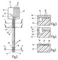
FIG. 2 shows a sensor system arranged according to FIG. 1 in a top-view; and
FIGS. 3 to 5 show sections along the lines 3-3, 4-4 and 5-5 of FIG. 2.
Skilled artisans appreciate that elements in the figures are illustrated for simplicity and clarity and have not necessarily been drawn to scale. For example, the dimensions of some of the elements in the figure may be exaggerated relative to other elements to help improve understanding of the embodiment(s) of the present invention.
DETAILED DESCRIPTION
The following description of the preferred embodiment is merely exemplary in nature and is in no way intended to limit the invention or its application or uses.
The monitoring system shown in FIG. 1 comprises a sensor system 10, a conveying unit 12 with a liquid reservoir 14, a signal processing unit 16 with an alarm trigger 18, a control unit 20 for the conveying unit 12 and a calibration device 22. The arrangement enables constituents (glucose) to be determined in the surrounding matrix by means of the subcutaneously implantable sensor system 10 and allows passage of a liquid.
As shown in FIG. 2 the sensor system 10 has a support 24, an electrochemical sensor 26 mounted thereon and an integrated fluid channel 28. The flexible support 24 is for example made from a flexible foil material as a substrate and at least a shaft region 30 thereof can be implanted into body tissue. An insertion aid (not shown) is used for this purpose which creates the necessary tissue opening. It is basically also possible that the support is made of an inflexible material in a needle-like design and can be directly inserted into the body tissue.
The sensor 26 comprises a working electrode 32, a counter electrode 34 and a reference electrode 36. The electrodes are in an electrically conducting contact with associated contact tongues 40 via respective conducting paths 38, said tongues being located on a connecting part 42 of the support 24 that is located outside the body tissue.
The working electrode 32 is characterized as an enzyme electrode in that an intermediate product is formed by the reaction of the analyte (glucose) with a specific enzyme and the intermediate product is converted electrochemically on the working electrode by applying a constant potential between the reference electrode and working electrode. As a result a measurement signal can be detected in a known manner which correlates with the glucose concentration. The potential between the reference electrode and working electrode can be kept constant by means of the reference electrode 36 using a potentiostat to prevent the electrochemical conversion of interfering substances.
The working electrode 32 can be provided with additional layers which serve as a diffusion barrier layer for glucose, as a barrier layer for interfering substances and as a biocompatible layer facing the tissue. The size of the counter electrode 34 is selected such that the current density and thus excess voltage is minimized. There are no constraints on the shape of the electrodes; rectangular or round electrode shapes are can be used. It is also possible that the electrodes intermesh. In each case the free surface of the electrodes forms an active sensor region 44 that can be brought into direct contact with the body tissue, said sensor area being arranged on the support 24 spatially separated from the fluid channel 28. It is also conceivable that several single sensors also have common electrodes in the form of a multielectrode system.
A liquid can be removed from or supplied to the body tissue through the fluid channel 28. For this purpose the fluid channel 28 has at least one opening 46 on the tissue side, at least one opening 48 located outside of the body tissue and at least one flow path 50 between the openings. The side of the flow path 50 is closed and the flow path can have a capillary-active cross-section of for example less than 1 mm2. Hence the liquid volume contained in the fluid channel 28 can also be kept low.
The opening 46 on the tissue side should be designed such that no significant increase in the hydrodynamic resistance relative to the flow path 50 due to body reactions in this region is detectable during the implantation time. For this purpose it is advantageous to design the surface around this opening 46 in such a manner that its permeability to the analyte or the active substance that is supplied in each case remains essentially unchanged during the period of implantation. For this purpose the physical and chemical properties, the microstructure and the morphology of the surface should be selected such that protein and cell adsorption is kept small. With regard to the chemical properties of the surface, a low surface charge is particularly advantageous.
As shown in FIGS. 3 to 5, the support 24 can be composed of multiple layers and in particular consists of a base foil 52, an insulating layer 54 and a cover layer 56. The flow path 50 or rather the liquid passage is produced by laser ablation, hot stamping or photolithography and is closed in a liquid-tight manner by the cover layer 56 with the exception of the openings 46, 48.
In the embodiment shown the subcutaneously implanted glucose sensor 26 is connected via the contact tongues 40 to the extracorporeal signal processing unit 16 in order to display a measuring result to the user that correlates with the glucose content of the interstitial fluid and thus also with the blood glucose and optionally to trigger an alarm via the alarm trigger 18 when it is outside the normoglycaemic range.
In order to carry out an automatic self calibration interstitial fluid can be removed or calibration solution can be supplied via the fluid channel 28 and the downstream conveying unit 12 such that their glucose content or constituent can be determined in parallel by means of the external calibration device 22 or the concentration is known. The calibration device 22 has a reference sensor 58 to which the tissue fluid can be applied. Hence it is possible to automatically carry out a calibration of the output signal of the body sensor 26 that is processed in the signal processing unit 16 at specified time intervals.
Whereas in the previously described embodiment the conveying unit 12 is provided as a pump for removing interstitial fluid, alternatively or in addition thereto a conveying unit 60 may be connected to the fluid channel 28 to feed a calibration solution into the body tissue or a metering unit 62 may be connected to the fluid channel 28 to administer a medication liquid which in particular contains insulin into the body tissue. This also allows the liquid flow rate or the dosage to be adjusted by means of control device 20. Optionally instead of a simple control chain, a closed control loop can be provided for the liquid transport.
The distance of the sensor 26 from the opening 46 of the fluid channel 28 on the tissue side can be varied depending on the composition of the delivered liquid. If a solution of a known analyte content is delivered, the distance should be as small as possible so that a direct change of the measured signal occurs after the liquid flows out from the opening 46. If a solution of an active substance (insulin) is supplied which influences the analyte concentration (glucose) in the tissue, the distance is selected such that at the given pressure difference between the opening 46 and tissue environment, at the given colloid osmotic pressure, at the given time period of liquid supply and at the given diffusion coefficient of the analyte no measurable change in the analyte concentration of the body fluid occurs in the direct vicinity of the sensor.
Another embodiment which is not specifically shown comprises two single sensors for the analyte which are spaced apart, one of the single sensors being located nearer to the tissue-side opening 46. This allows a detection of two different subcutaneous sites which is advantageous due to the inhomogeneity of the subcutaneous tissue and of the respective tissue reaction. Furthermore, when solutions of active substances are delivered via the fluid channel 28, an interaction of the active substance with the surrounding tissue can be determined with the aid of one of the single sensors in order to detect a disease state or for therapeutic monitoring, while the delivery of the solution of active substance can be controlled by means of the other single sensor. Using the said single sensors it is also possible to separately determine an analyte and an active substance fed in via the fluid channel 28. In this case the analyte sensor should be at a greater distance from the opening 46 than the active substance sensor. In addition to determining the analyte concentration, this also enables the active substance to be determined in the surrounding tissue thus allowing a detection of a disease state and therapeutic monitoring.
It is also conceivable that two analyte sensors and one active substance sensor are provided where the first analyte sensor is at a greater distance from the opening 46 on the tissue side than the second analyte sensor and than the active substance sensor.
As shown by numerous studies, a tissue capsule forms around an object implanted in tissue in the process of wound healing. The thickness of the fibrous tissue capsule depends on the size of the object itself. It may be assumed that the fibrous capsule represents a diffusion barrier for an implanted sensor. These problems become particularly pronounced when an adequate amount of a fluid transport medium is necessary to deliver the analyte from the tissue environment to the sensor.
In contrast with the measures according to the invention the success of the measurement does not depend on the amount of interstitial fluid which is hardly present particularly in subcutaneous tissue. Hence the measurement is hardly affected by other influencing factors such as pressure, movement and position of the tissue, which influence the tissue content of interstitial fluid. An insertion set that can be cost-effectively manufactured, that is miniaturized and thus causes minimum damage to the body tissue is created for the improved use of flexible thin layer sensors for measuring constituents in a body tissue. In addition to measurement with an optimized response time it is possible to feed liquids into or out of a separate area of body tissue. This avoids the disadvantages of the prior art and above all the significant measurement errors due to body tissue injury caused by rigid and macroscopic needle sensors and the high manufacturing costs due to the complex construction. In particular it is not necessary to pass through a dialysis fluid because the implanted sensor is directly contacted with the tissue i.e. with the cells, the vessels and the supporting matrix. This makes measurement in interstitial fluid obsolete.
It is noted that terms like “preferably”, “commonly”, and “typically” are not utilized herein to limit the scope of the claimed invention or to imply that certain features are critical, essential, or even important to the structure or function of the claimed invention. Rather, these terms are merely intended to highlight alternative or additional features that may or may not be utilized in a particular embodiment of the present invention.
For the purposes of describing and defining the present invention it is noted that the term “substantially” is utilized herein to represent the inherent degree of uncertainty that may be attributed to any quantitative comparison, value, measurement, or other representation. The term “substantially” is also utilized herein to represent the degree by which a quantitative representation may vary from a stated reference without resulting in a change in the basic function of the subject matter at issue.
Having described the invention in detail and by reference to specific embodiments thereof, it will be apparent that modification and variations are possible without departing from the scope of the invention defined in the appended claims. More specifically, although some aspects of the present invention are identified herein as preferred or particularly advantageous, it is contemplated that the present invention is not necessarily limited to these preferred aspects of the invention.

Claims (22)

What is claimed is:
1. An analyte monitoring sensor system comprising:
a support that can be at least partially inserted into body tissue;
a fluid channel arranged on the support for passing through a liquid; and
a sensor that responds to a constituent of the liquid and/or the body tissue, wherein the sensor is arranged on the support and configured for direct contact with the body tissue separately from the fluid channel, and wherein the fluid channel is in fluid communication with a metering unit to feed a liquid into the body tissue.
2. The sensor system of claim 1, wherein the sensor is arranged on a surface of the support which, when inserted, is in contact with the body tissue.
3. The sensor system of claim 2, wherein the sensor in a multielectrode configuration has several electrodes arranged on the surface of the support which engages with the body tissue.
4. The sensor system of claim 1, wherein the sensor responds directly to the constituent independently of the amount of the locally present tissue fluid.
5. The sensor system of claim 1, wherein the sensor is in direct engagement with the body tissue at a distance from an opening of the fluid channel on an active sensor region side.
6. The sensor system of claim 1, wherein an interstitial fluid and/or a calibration solution can be fed via the fluid channel to a calibration device for the sensor that is located outside of the body tissue.
7. The sensor system of claim 6, wherein the calibration device has a reference sensor to calibrate the output signals of the sensor.
8. The sensor system of claim 1, wherein the fluid channel is connected to a pumping unit to remove interstitial fluid from the body tissue.
9. The sensor system of claim 1, wherein the analyte is glucose and the liquid fed into the body tissue is insulin.
10. The sensor system of claim 1, wherein the fluid channel is connected to a conveying unit to feed a calibration solution into the body tissue.
11. The sensor system of claim 1, wherein the sensor has an active sensor region that can be brought into contact with the body tissue.
12. The sensor system of claim 1, wherein the sensor is designed to continuously detect glucose as a constituent in the interstitial fluid.
13. The sensor system of claim 1, wherein the support is formed by a flexible flat substrate and wherein the fluid channel and the sensor are designed as a thin layer structure integrated on the substrate as a composite part.
14. The sensor system of claim 13, wherein the flexible support is configured for insertion into the body tissue by utilizing an insertion aid.
15. The sensor system of claim 1, wherein the fluid channel has at least one opening on an active region side, at least one opening located outside of the body tissue and at least one flow path between the openings that is a capillary flow path.
16. The sensor system of claim 1, wherein the fluid channel is integrated into an optionally multi-part support by laser treatment, hot stamping or photolithography.
17. The sensor system of claim 1, wherein the fluid channel has a flow cross-section of less than 1 mm2.
18. The sensor system of claim 1, wherein the fluid channel opens onto the surface of the support carrying the sensor in a detection area of the sensor.
19. The sensor system of claim 1, wherein the fluid channel flows into a part of the support that faces away from or is distant from the sensor and is outside of the detection area of the sensor.
20. The sensor system of claim 1, wherein the sensor comprises at least two single sensors that are at different distances from an opening of the fluid channel on the tissue side.
21. The sensor system of claim 1, wherein the sensor has a single sensor for glucose and a single sensor for an active substance that can be passed into the body tissue through the fluid channel.
22. The sensor system of claim 1, wherein the support is configured for partial insertion into a subcutaneous tissue.
US13/110,335 2005-06-17 2011-05-18 Analyte monitoring sensor system for monitoring a constituent in body tissue Active 2028-07-12 US8942778B2 (en)

Priority Applications (1)

Application Number Priority Date Filing Date Title
US13/110,335 US8942778B2 (en) 2005-06-17 2011-05-18 Analyte monitoring sensor system for monitoring a constituent in body tissue

Applications Claiming Priority (5)

Application Number Priority Date Filing Date Title
EP05013063.2 2005-06-17
EP05013063A EP1733676B1 (en) 2005-06-17 2005-06-17 Sensor system, arrangement and method for monitoring a compound, in particular glucose in body tissue.
EP05013063 2005-06-17
US11/425,020 US7967752B2 (en) 2005-06-17 2006-06-19 Sensor system as well as an arrangement and method for monitoring a constituent and in particular glucose in body tissue
US13/110,335 US8942778B2 (en) 2005-06-17 2011-05-18 Analyte monitoring sensor system for monitoring a constituent in body tissue

Related Parent Applications (1)

Application Number Title Priority Date Filing Date
US11/425,020 Continuation US7967752B2 (en) 2005-06-17 2006-06-19 Sensor system as well as an arrangement and method for monitoring a constituent and in particular glucose in body tissue

Publications (2)

Publication Number Publication Date
US20110218490A1 US20110218490A1 (en) 2011-09-08
US8942778B2 true US8942778B2 (en) 2015-01-27

Family

ID=35478764

Family Applications (2)

Application Number Title Priority Date Filing Date
US11/425,020 Expired - Fee Related US7967752B2 (en) 2005-06-17 2006-06-19 Sensor system as well as an arrangement and method for monitoring a constituent and in particular glucose in body tissue
US13/110,335 Active 2028-07-12 US8942778B2 (en) 2005-06-17 2011-05-18 Analyte monitoring sensor system for monitoring a constituent in body tissue

Family Applications Before (1)

Application Number Title Priority Date Filing Date
US11/425,020 Expired - Fee Related US7967752B2 (en) 2005-06-17 2006-06-19 Sensor system as well as an arrangement and method for monitoring a constituent and in particular glucose in body tissue

Country Status (6)

Country Link
US (2) US7967752B2 (en)
EP (2) EP1733676B1 (en)
JP (1) JP2006346454A (en)
CA (1) CA2550171A1 (en)
DK (1) DK2260759T3 (en)
PL (1) PL2260759T3 (en)

Cited By (5)

* Cited by examiner, † Cited by third party
Publication number Priority date Publication date Assignee Title
US20130245401A1 (en) * 2012-03-16 2013-09-19 Dexcom, Inc. Systems and methods for processing analyte sensor data
US9801575B2 (en) 2011-04-15 2017-10-31 Dexcom, Inc. Advanced analyte sensor calibration and error detection
US11000215B1 (en) 2003-12-05 2021-05-11 Dexcom, Inc. Analyte sensor
US11331022B2 (en) 2017-10-24 2022-05-17 Dexcom, Inc. Pre-connected analyte sensors
US11350862B2 (en) 2017-10-24 2022-06-07 Dexcom, Inc. Pre-connected analyte sensors

Families Citing this family (53)

* Cited by examiner, † Cited by third party
Publication number Priority date Publication date Assignee Title
US7381184B2 (en) 2002-11-05 2008-06-03 Abbott Diabetes Care Inc. Sensor inserter assembly
US20040253736A1 (en) * 2003-06-06 2004-12-16 Phil Stout Analytical device with prediction module and related methods
USD914881S1 (en) 2003-11-05 2021-03-30 Abbott Diabetes Care Inc. Analyte sensor electronic mount
US8333714B2 (en) 2006-09-10 2012-12-18 Abbott Diabetes Care Inc. Method and system for providing an integrated analyte sensor insertion device and data processing unit
US7697967B2 (en) 2005-12-28 2010-04-13 Abbott Diabetes Care Inc. Method and apparatus for providing analyte sensor insertion
US7883464B2 (en) 2005-09-30 2011-02-08 Abbott Diabetes Care Inc. Integrated transmitter unit and sensor introducer mechanism and methods of use
US8029441B2 (en) 2006-02-28 2011-10-04 Abbott Diabetes Care Inc. Analyte sensor transmitter unit configuration for a data monitoring and management system
US8512243B2 (en) 2005-09-30 2013-08-20 Abbott Diabetes Care Inc. Integrated introducer and transmitter assembly and methods of use
US10226207B2 (en) 2004-12-29 2019-03-12 Abbott Diabetes Care Inc. Sensor inserter having introducer
US9788771B2 (en) 2006-10-23 2017-10-17 Abbott Diabetes Care Inc. Variable speed sensor insertion devices and methods of use
US9636450B2 (en) 2007-02-19 2017-05-02 Udo Hoss Pump system modular components for delivering medication and analyte sensing at seperate insertion sites
US9398882B2 (en) 2005-09-30 2016-07-26 Abbott Diabetes Care Inc. Method and apparatus for providing analyte sensor and data processing device
US9259175B2 (en) 2006-10-23 2016-02-16 Abbott Diabetes Care, Inc. Flexible patch for fluid delivery and monitoring body analytes
US9572534B2 (en) 2010-06-29 2017-02-21 Abbott Diabetes Care Inc. Devices, systems and methods for on-skin or on-body mounting of medical devices
US20090105569A1 (en) 2006-04-28 2009-04-23 Abbott Diabetes Care, Inc. Introducer Assembly and Methods of Use
US9521968B2 (en) 2005-09-30 2016-12-20 Abbott Diabetes Care Inc. Analyte sensor retention mechanism and methods of use
US8880138B2 (en) 2005-09-30 2014-11-04 Abbott Diabetes Care Inc. Device for channeling fluid and methods of use
US11298058B2 (en) 2005-12-28 2022-04-12 Abbott Diabetes Care Inc. Method and apparatus for providing analyte sensor insertion
US7826879B2 (en) 2006-02-28 2010-11-02 Abbott Diabetes Care Inc. Analyte sensors and methods of use
US20080199894A1 (en) 2007-02-15 2008-08-21 Abbott Diabetes Care, Inc. Device and method for automatic data acquisition and/or detection
US20080275326A1 (en) * 2007-05-01 2008-11-06 Joachim Kasielke Sensor for monitoring a condition of a patient
JP5680960B2 (en) 2007-06-21 2015-03-04 アボット ダイアベティス ケア インコーポレイテッドAbbott Diabetes Care Inc. Health care device and method
US8000918B2 (en) * 2007-10-23 2011-08-16 Edwards Lifesciences Corporation Monitoring and compensating for temperature-related error in an electrochemical sensor
WO2010009172A1 (en) 2008-07-14 2010-01-21 Abbott Diabetes Care Inc. Closed loop control system interface and methods
EP2163190A1 (en) * 2008-09-11 2010-03-17 Roche Diagnostics GmbH Electrode system for measurement of an analyte concentration in-vivo
US9402544B2 (en) 2009-02-03 2016-08-02 Abbott Diabetes Care Inc. Analyte sensor and apparatus for insertion of the sensor
US9184490B2 (en) 2009-05-29 2015-11-10 Abbott Diabetes Care Inc. Medical device antenna systems having external antenna configurations
DK3689237T3 (en) 2009-07-23 2021-08-16 Abbott Diabetes Care Inc Method of preparation and system for continuous analyte measurement
WO2011014704A2 (en) 2009-07-30 2011-02-03 Tandem Diabetes Care, Inc. Infusion pump system with disposable cartridge having pressure venting and pressure feedback
EP3923295A1 (en) 2009-08-31 2021-12-15 Abbott Diabetes Care, Inc. Medical devices and methods
EP2545853B1 (en) * 2010-03-09 2017-10-25 ARKRAY, Inc. Electrochemical sensor
ES2881798T3 (en) 2010-03-24 2021-11-30 Abbott Diabetes Care Inc Medical device inserters and medical device insertion and use procedures
US11064921B2 (en) 2010-06-29 2021-07-20 Abbott Diabetes Care Inc. Devices, systems and methods for on-skin or on-body mounting of medical devices
CN103619255B (en) 2011-02-28 2016-11-02 雅培糖尿病护理公司 The device that associates with analyte monitoring device, system and method and combine their device
US20140235974A1 (en) * 2011-10-11 2014-08-21 Edward Lifesciences Corporation Integrated calibrant measurement system for analyte sensors
WO2013066873A1 (en) 2011-10-31 2013-05-10 Abbott Diabetes Care Inc. Electronic devices having integrated reset systems and methods thereof
FI3300658T3 (en) 2011-12-11 2024-03-01 Abbott Diabetes Care Inc Analyte sensor methods
WO2014007890A2 (en) * 2012-03-29 2014-01-09 California Institute Of Technology Sensor probe for bio-sensing and chemical-sensing applications
US9180242B2 (en) 2012-05-17 2015-11-10 Tandem Diabetes Care, Inc. Methods and devices for multiple fluid transfer
WO2014018286A1 (en) 2012-07-25 2014-01-30 California Institute Of Technology Nanopillar field-effect and junction transistors with functionalized gate and base electrodes
US20140190839A1 (en) * 2012-08-06 2014-07-10 Google Inc. Contact lenses having two-electrode electrochemical sensors
US8883645B2 (en) 2012-11-09 2014-11-11 California Institute Of Technology Nanopillar field-effect and junction transistors
WO2014093021A1 (en) * 2012-12-12 2014-06-19 Edwards Lifesciences Corporation System for controlling presentation of an estimated analyte value
US9173998B2 (en) 2013-03-14 2015-11-03 Tandem Diabetes Care, Inc. System and method for detecting occlusions in an infusion pump
US9770196B2 (en) * 2013-11-27 2017-09-26 Universiteit Gent Sensing of components in liquids
WO2016183493A1 (en) 2015-05-14 2016-11-17 Abbott Diabetes Care Inc. Compact medical device inserters and related systems and methods
US10213139B2 (en) 2015-05-14 2019-02-26 Abbott Diabetes Care Inc. Systems, devices, and methods for assembling an applicator and sensor control device
US10780222B2 (en) 2015-06-03 2020-09-22 Pacific Diabetes Technologies Inc Measurement of glucose in an insulin delivery catheter by minimizing the adverse effects of insulin preservatives
CN105445345B (en) * 2015-11-12 2018-06-05 三诺生物传感股份有限公司 A kind of preparation method of flexibility implant electrode
CN110461217B (en) 2017-01-23 2022-09-16 雅培糖尿病护理公司 Systems, devices, and methods for analyte sensor insertion
EP3890608A4 (en) * 2018-12-03 2022-08-24 Laxmi Therapeutic Devices, Inc. Needles for measurement of body fluid analytes such as glucose
USD1002852S1 (en) 2019-06-06 2023-10-24 Abbott Diabetes Care Inc. Analyte sensor device
USD999913S1 (en) 2020-12-21 2023-09-26 Abbott Diabetes Care Inc Analyte sensor inserter

Citations (17)

* Cited by examiner, † Cited by third party
Publication number Priority date Publication date Assignee Title
WO1981001794A1 (en) 1979-12-28 1981-07-09 S Ash System for demand-based administration of insulin
US5269891A (en) * 1989-03-09 1993-12-14 Novo Nordisk A/S Method and apparatus for determination of a constituent in a fluid
WO1996014026A1 (en) 1994-11-04 1996-05-17 Elan Medical Technologies Limited Analyte-controlled liquid delivery device and analyte monitor
US5586553A (en) 1995-02-16 1996-12-24 Minimed Inc. Transcutaneous sensor insertion set
WO1999065388A1 (en) 1998-06-19 1999-12-23 Alfred E. Mann Foundation For Scientific Research Substrate sensor
WO2001093930A1 (en) 2000-06-02 2001-12-13 The University Of Utah Research Foundation Active needle devices with integrated functionality
US20020022782A1 (en) * 1999-03-03 2002-02-21 Kiepen Horst F. Flexible elongate member having one or more electrical contacts
WO2002039086A2 (en) 2000-11-13 2002-05-16 Nipro Diabetes Systems Glucose sensor system
US20020137998A1 (en) 2001-03-26 2002-09-26 Wilson Smart Silicon microprobe with integrated biosensor
US6558351B1 (en) 1999-06-03 2003-05-06 Medtronic Minimed, Inc. Closed loop system for controlling insulin infusion
US20030125613A1 (en) 2001-12-27 2003-07-03 Medtronic Minimed, Inc. Implantable sensor flush sleeve
US20030130616A1 (en) * 1999-06-03 2003-07-10 Medtronic Minimed, Inc. Closed loop system for controlling insulin infusion
US20050033133A1 (en) 2003-08-06 2005-02-10 Clifford Kraft Implantable chip medical diagnostic device for bodily fluids
US20060258959A1 (en) * 2003-09-02 2006-11-16 Koji Sode Glucose sensor and glucose level measuring apparatus
US7169117B2 (en) * 2003-03-28 2007-01-30 Lifescan, Inc. Integrated lance and strip for analyte measurement
US7415299B2 (en) * 2003-04-18 2008-08-19 The Regents Of The University Of California Monitoring method and/or apparatus
US7445766B2 (en) * 2000-03-02 2008-11-04 Microchips, Inc. Medical device and method for diagnostic sensing

Patent Citations (18)

* Cited by examiner, † Cited by third party
Publication number Priority date Publication date Assignee Title
WO1981001794A1 (en) 1979-12-28 1981-07-09 S Ash System for demand-based administration of insulin
US5269891A (en) * 1989-03-09 1993-12-14 Novo Nordisk A/S Method and apparatus for determination of a constituent in a fluid
WO1996014026A1 (en) 1994-11-04 1996-05-17 Elan Medical Technologies Limited Analyte-controlled liquid delivery device and analyte monitor
US5586553A (en) 1995-02-16 1996-12-24 Minimed Inc. Transcutaneous sensor insertion set
WO1999065388A1 (en) 1998-06-19 1999-12-23 Alfred E. Mann Foundation For Scientific Research Substrate sensor
US20020022782A1 (en) * 1999-03-03 2002-02-21 Kiepen Horst F. Flexible elongate member having one or more electrical contacts
US6558351B1 (en) 1999-06-03 2003-05-06 Medtronic Minimed, Inc. Closed loop system for controlling insulin infusion
US20030130616A1 (en) * 1999-06-03 2003-07-10 Medtronic Minimed, Inc. Closed loop system for controlling insulin infusion
US7445766B2 (en) * 2000-03-02 2008-11-04 Microchips, Inc. Medical device and method for diagnostic sensing
US20040176732A1 (en) * 2000-06-02 2004-09-09 Frazier A Bruno Active needle devices with integrated functionality
WO2001093930A1 (en) 2000-06-02 2001-12-13 The University Of Utah Research Foundation Active needle devices with integrated functionality
WO2002039086A2 (en) 2000-11-13 2002-05-16 Nipro Diabetes Systems Glucose sensor system
US20020137998A1 (en) 2001-03-26 2002-09-26 Wilson Smart Silicon microprobe with integrated biosensor
US20030125613A1 (en) 2001-12-27 2003-07-03 Medtronic Minimed, Inc. Implantable sensor flush sleeve
US7169117B2 (en) * 2003-03-28 2007-01-30 Lifescan, Inc. Integrated lance and strip for analyte measurement
US7415299B2 (en) * 2003-04-18 2008-08-19 The Regents Of The University Of California Monitoring method and/or apparatus
US20050033133A1 (en) 2003-08-06 2005-02-10 Clifford Kraft Implantable chip medical diagnostic device for bodily fluids
US20060258959A1 (en) * 2003-09-02 2006-11-16 Koji Sode Glucose sensor and glucose level measuring apparatus

Non-Patent Citations (1)

* Cited by examiner, † Cited by third party
Title
JP Office Action received Sep. 7, 2009 in counterpart JP application.

Cited By (28)

* Cited by examiner, † Cited by third party
Publication number Priority date Publication date Assignee Title
US11627900B2 (en) 2003-12-05 2023-04-18 Dexcom, Inc. Analyte sensor
US11020031B1 (en) 2003-12-05 2021-06-01 Dexcom, Inc. Analyte sensor
US11000215B1 (en) 2003-12-05 2021-05-11 Dexcom, Inc. Analyte sensor
US10980461B2 (en) 2008-11-07 2021-04-20 Dexcom, Inc. Advanced analyte sensor calibration and error detection
US10682084B2 (en) 2011-04-15 2020-06-16 Dexcom, Inc. Advanced analyte sensor calibration and error detection
US10722162B2 (en) 2011-04-15 2020-07-28 Dexcom, Inc. Advanced analyte sensor calibration and error detection
US10004442B2 (en) 2011-04-15 2018-06-26 Dexcom, Inc. Advanced analyte sensor calibration and error detection
US10327688B2 (en) 2011-04-15 2019-06-25 Dexcom, Inc. Advanced analyte sensor calibration and error detection
US10448873B2 (en) 2011-04-15 2019-10-22 Dexcom, Inc. Advanced analyte sensor calibration and error detection
US10555695B2 (en) 2011-04-15 2020-02-11 Dexcom, Inc. Advanced analyte sensor calibration and error detection
US10561354B2 (en) 2011-04-15 2020-02-18 Dexcom, Inc. Advanced analyte sensor calibration and error detection
US20210369149A1 (en) * 2011-04-15 2021-12-02 Dexcom, Inc. Advanced analyte sensor calibration and error detection
US10610141B2 (en) 2011-04-15 2020-04-07 Dexcom, Inc. Advanced analyte sensor calibration and error detection
US10624568B2 (en) 2011-04-15 2020-04-21 Dexcom, Inc. Advanced analyte sensor calibration and error detection
US9801575B2 (en) 2011-04-15 2017-10-31 Dexcom, Inc. Advanced analyte sensor calibration and error detection
US9848809B2 (en) 2011-04-15 2017-12-26 Dexcom, Inc. Advanced analyte sensor calibration and error detection
US10835162B2 (en) 2011-04-15 2020-11-17 Dexcom, Inc. Advanced analyte sensor calibration and error detection
US9808190B2 (en) 2011-04-15 2017-11-07 Dexcom, Inc. Advanced analyte sensor calibration and error detection
US10987040B2 (en) 2012-03-16 2021-04-27 Dexcom, Inc. Systems and methods for processing analyte sensor data
US20130245401A1 (en) * 2012-03-16 2013-09-19 Dexcom, Inc. Systems and methods for processing analyte sensor data
US9700253B2 (en) 2012-03-16 2017-07-11 Dexcom, Inc. Systems and methods for processing analyte sensor data
US10588557B2 (en) 2012-03-16 2020-03-17 Dexcom, Inc. Systems and methods for processing analyte sensor data
US9433376B2 (en) * 2012-03-16 2016-09-06 Dexcom, Inc. Systems and methods for processing analyte sensor data
US11331022B2 (en) 2017-10-24 2022-05-17 Dexcom, Inc. Pre-connected analyte sensors
US11350862B2 (en) 2017-10-24 2022-06-07 Dexcom, Inc. Pre-connected analyte sensors
US11382540B2 (en) 2017-10-24 2022-07-12 Dexcom, Inc. Pre-connected analyte sensors
US11706876B2 (en) 2017-10-24 2023-07-18 Dexcom, Inc. Pre-connected analyte sensors
US11943876B2 (en) 2017-10-24 2024-03-26 Dexcom, Inc. Pre-connected analyte sensors

Also Published As

Publication number Publication date
EP1733676A1 (en) 2006-12-20
PL2260759T3 (en) 2015-10-30
CA2550171A1 (en) 2006-12-17
US7967752B2 (en) 2011-06-28
EP1733676B1 (en) 2012-08-01
DK2260759T3 (en) 2015-08-17
JP2006346454A (en) 2006-12-28
EP2260759A3 (en) 2010-12-29
EP2260759A2 (en) 2010-12-15
EP2260759B1 (en) 2015-05-06
US20110218490A1 (en) 2011-09-08
US20060287591A1 (en) 2006-12-21

Similar Documents

Publication Publication Date Title
US8942778B2 (en) Analyte monitoring sensor system for monitoring a constituent in body tissue
US6013029A (en) Monitoring the concentration of a substance or a group of substances in a body fluid
US20070151868A1 (en) Implantable electrode system, method and apparatus for measuring an analyte concentration in a human or animal body
JP5624322B2 (en) Liquid supply with in-vivo electrochemical analyte sensing
US8382700B2 (en) Medical device for glucose monitoring or regulation
KR101115272B1 (en) System and method for operating an electrochemical analyte sensor
US10060877B2 (en) Electrochemical sensor for determining an analyte concentration
US11859231B2 (en) Multilayer electrochemical analyte sensors and methods for making and using them
Kyle et al. Measurement of delivery and metabolism of tirapazamine to tumour tissue using the multilayered cell culture model
WO2002039086A9 (en) Glucose sensor system
JP2011507556A5 (en)
NZ295458A (en) Liquid delivery device attached to patient's skin, liquid injected by gas from microprocessor controlled gas generator
US20180020981A1 (en) Modular biofluid sensing subsystems and devices
US11718865B2 (en) Methods to improve oxygen delivery to implantable sensors
US20210212605A1 (en) Biocompatible sleeve for glucose sensors
US20230080129A1 (en) Glucose sensor based on open circuit potential (ocp) signal
WO2011034629A1 (en) Devices and methods for metering insoluble active agent particles

Legal Events

Date Code Title Description
AS Assignment

Owner name: ROCHE DIAGNOSTICS OPERATIONS, INC., INDIANA

Free format text: ASSIGNMENT OF ASSIGNORS INTEREST;ASSIGNOR:ROCHE DIAGNOSTICS GMBH;REEL/FRAME:026307/0538

Effective date: 20060713

Owner name: ROCHE DIAGNOSTICS GMBH, GERMANY

Free format text: ASSIGNMENT OF ASSIGNORS INTEREST;ASSIGNORS:OCVIRK, GREGOR;RINNE, HELMUT;STAIB, ARNULF;SIGNING DATES FROM 20060704 TO 20060713;REEL/FRAME:026307/0512

STCF Information on status: patent grant

Free format text: PATENTED CASE

AS Assignment

Owner name: ROCHE DIABETES CARE, INC., INDIANA

Free format text: ASSIGNMENT OF ASSIGNORS INTEREST;ASSIGNOR:ROCHE DIAGNOSTICS OPERATIONS, INC.;REEL/FRAME:036008/0670

Effective date: 20150302

MAFP Maintenance fee payment

Free format text: PAYMENT OF MAINTENANCE FEE, 4TH YEAR, LARGE ENTITY (ORIGINAL EVENT CODE: M1551)

Year of fee payment: 4

MAFP Maintenance fee payment

Free format text: PAYMENT OF MAINTENANCE FEE, 8TH YEAR, LARGE ENTITY (ORIGINAL EVENT CODE: M1552); ENTITY STATUS OF PATENT OWNER: LARGE ENTITY

Year of fee payment: 8