US8948222B1 - Laser diode light source - Google Patents
Laser diode light source Download PDFInfo
- Publication number
- US8948222B1 US8948222B1 US14/042,094 US201314042094A US8948222B1 US 8948222 B1 US8948222 B1 US 8948222B1 US 201314042094 A US201314042094 A US 201314042094A US 8948222 B1 US8948222 B1 US 8948222B1
- Authority
- US
- United States
- Prior art keywords
- dithering
- light
- light source
- peak
- laser
- Prior art date
- Legal status (The legal status is an assumption and is not a legal conclusion. Google has not performed a legal analysis and makes no representation as to the accuracy of the status listed.)
- Active
Links
Images


Classifications
-
- H—ELECTRICITY
- H01—ELECTRIC ELEMENTS
- H01S—DEVICES USING THE PROCESS OF LIGHT AMPLIFICATION BY STIMULATED EMISSION OF RADIATION [LASER] TO AMPLIFY OR GENERATE LIGHT; DEVICES USING STIMULATED EMISSION OF ELECTROMAGNETIC RADIATION IN WAVE RANGES OTHER THAN OPTICAL
- H01S5/00—Semiconductor lasers
- H01S5/06—Arrangements for controlling the laser output parameters, e.g. by operating on the active medium
- H01S5/062—Arrangements for controlling the laser output parameters, e.g. by operating on the active medium by varying the potential of the electrodes
- H01S5/06233—Controlling other output parameters than intensity or frequency
- H01S5/0624—Controlling other output parameters than intensity or frequency controlling the near- or far field
-
- H—ELECTRICITY
- H01—ELECTRIC ELEMENTS
- H01S—DEVICES USING THE PROCESS OF LIGHT AMPLIFICATION BY STIMULATED EMISSION OF RADIATION [LASER] TO AMPLIFY OR GENERATE LIGHT; DEVICES USING STIMULATED EMISSION OF ELECTROMAGNETIC RADIATION IN WAVE RANGES OTHER THAN OPTICAL
- H01S5/00—Semiconductor lasers
- H01S5/06—Arrangements for controlling the laser output parameters, e.g. by operating on the active medium
- H01S5/062—Arrangements for controlling the laser output parameters, e.g. by operating on the active medium by varying the potential of the electrodes
- H01S5/0625—Arrangements for controlling the laser output parameters, e.g. by operating on the active medium by varying the potential of the electrodes in multi-section lasers
- H01S5/06251—Amplitude modulation
-
- H—ELECTRICITY
- H01—ELECTRIC ELEMENTS
- H01S—DEVICES USING THE PROCESS OF LIGHT AMPLIFICATION BY STIMULATED EMISSION OF RADIATION [LASER] TO AMPLIFY OR GENERATE LIGHT; DEVICES USING STIMULATED EMISSION OF ELECTROMAGNETIC RADIATION IN WAVE RANGES OTHER THAN OPTICAL
- H01S5/00—Semiconductor lasers
- H01S5/06—Arrangements for controlling the laser output parameters, e.g. by operating on the active medium
- H01S5/062—Arrangements for controlling the laser output parameters, e.g. by operating on the active medium by varying the potential of the electrodes
- H01S5/06209—Arrangements for controlling the laser output parameters, e.g. by operating on the active medium by varying the potential of the electrodes in single-section lasers
- H01S5/06213—Amplitude modulation
-
- H—ELECTRICITY
- H01—ELECTRIC ELEMENTS
- H01S—DEVICES USING THE PROCESS OF LIGHT AMPLIFICATION BY STIMULATED EMISSION OF RADIATION [LASER] TO AMPLIFY OR GENERATE LIGHT; DEVICES USING STIMULATED EMISSION OF ELECTROMAGNETIC RADIATION IN WAVE RANGES OTHER THAN OPTICAL
- H01S5/00—Semiconductor lasers
- H01S5/40—Arrangement of two or more semiconductor lasers, not provided for in groups H01S5/02 - H01S5/30
- H01S5/4012—Beam combining, e.g. by the use of fibres, gratings, polarisers, prisms
-
- H—ELECTRICITY
- H01—ELECTRIC ELEMENTS
- H01S—DEVICES USING THE PROCESS OF LIGHT AMPLIFICATION BY STIMULATED EMISSION OF RADIATION [LASER] TO AMPLIFY OR GENERATE LIGHT; DEVICES USING STIMULATED EMISSION OF ELECTROMAGNETIC RADIATION IN WAVE RANGES OTHER THAN OPTICAL
- H01S3/00—Lasers, i.e. devices using stimulated emission of electromagnetic radiation in the infrared, visible or ultraviolet wave range
- H01S3/09—Processes or apparatus for excitation, e.g. pumping
- H01S3/091—Processes or apparatus for excitation, e.g. pumping using optical pumping
- H01S3/094—Processes or apparatus for excitation, e.g. pumping using optical pumping by coherent light
- H01S3/0941—Processes or apparatus for excitation, e.g. pumping using optical pumping by coherent light of a laser diode
-
- H—ELECTRICITY
- H01—ELECTRIC ELEMENTS
- H01S—DEVICES USING THE PROCESS OF LIGHT AMPLIFICATION BY STIMULATED EMISSION OF RADIATION [LASER] TO AMPLIFY OR GENERATE LIGHT; DEVICES USING STIMULATED EMISSION OF ELECTROMAGNETIC RADIATION IN WAVE RANGES OTHER THAN OPTICAL
- H01S5/00—Semiconductor lasers
- H01S5/005—Optical components external to the laser cavity, specially adapted therefor, e.g. for homogenisation or merging of the beams or for manipulating laser pulses, e.g. pulse shaping
-
- H—ELECTRICITY
- H01—ELECTRIC ELEMENTS
- H01S—DEVICES USING THE PROCESS OF LIGHT AMPLIFICATION BY STIMULATED EMISSION OF RADIATION [LASER] TO AMPLIFY OR GENERATE LIGHT; DEVICES USING STIMULATED EMISSION OF ELECTROMAGNETIC RADIATION IN WAVE RANGES OTHER THAN OPTICAL
- H01S5/00—Semiconductor lasers
- H01S5/02—Structural details or components not essential to laser action
- H01S5/022—Mountings; Housings
- H01S5/0225—Out-coupling of light
- H01S5/02251—Out-coupling of light using optical fibres
-
- H—ELECTRICITY
- H01—ELECTRIC ELEMENTS
- H01S—DEVICES USING THE PROCESS OF LIGHT AMPLIFICATION BY STIMULATED EMISSION OF RADIATION [LASER] TO AMPLIFY OR GENERATE LIGHT; DEVICES USING STIMULATED EMISSION OF ELECTROMAGNETIC RADIATION IN WAVE RANGES OTHER THAN OPTICAL
- H01S5/00—Semiconductor lasers
- H01S5/06—Arrangements for controlling the laser output parameters, e.g. by operating on the active medium
- H01S5/065—Mode locking; Mode suppression; Mode selection ; Self pulsating
- H01S5/0651—Mode control
- H01S5/0653—Mode suppression, e.g. specific multimode
-
- H—ELECTRICITY
- H01—ELECTRIC ELEMENTS
- H01S—DEVICES USING THE PROCESS OF LIGHT AMPLIFICATION BY STIMULATED EMISSION OF RADIATION [LASER] TO AMPLIFY OR GENERATE LIGHT; DEVICES USING STIMULATED EMISSION OF ELECTROMAGNETIC RADIATION IN WAVE RANGES OTHER THAN OPTICAL
- H01S5/00—Semiconductor lasers
- H01S5/40—Arrangement of two or more semiconductor lasers, not provided for in groups H01S5/02 - H01S5/30
- H01S5/4025—Array arrangements, e.g. constituted by discrete laser diodes or laser bar
- H01S5/4031—Edge-emitting structures
Definitions
- the present invention relates to light sources, and in particular to light sources utilizing laser diodes, and methods of operating such light sources.
- Laser diodes are inexpensive and efficient sources of coherent light at high power density and spectral brightness. They are widely used in electro-optical devices ranging from CD players to concrete-cutting industrial lasers. In industrial lasers, laser diodes are frequently used as a pump source for rare earth doped fibers or rods. Laser diodes are also widespread in optical fiber amplifiers, where they are used to pump erbium doped optical fibers.
- Reliability is one of the most important parameters of laser diodes. Many factors impact reliability. For example, chip construction, packaging, and heat sinking of laser diode chips can be big factors. When the laser diode chips and packages are properly constructed, the life expectancy of the laser diodes can reach hundreds of thousands of hours.
- a common location of failure of a laser diode is its light-emitting end facet, where light intensity is extremely high. Even a minute contamination of the facet, or a minor defect of its crystalline structure, can lead to a catastrophic thermal runaway, forming a melted area or a micro-explosion at the facet, degrading or even completely disabling the laser diode.
- Non-radiative electric currents generated in vicinity of laser diode end facets can generate heat, which causes the end facets degradation.
- Yamanaka in U.S. Pat. No. 6,678,303 discloses a laser diode, in which recesses are formed in the doped layers above and below the p-n junction, to prevent the non-radiative currents from reaching the end facet.
- Schmidt et al. in US Patent Application Publication 2008/0273563 disclose a ridge-type laser diode, in which degradation of a front section of a ridge-type laser diode is lessened by providing a trench or gap on the ridge between an active section and the front section. The gap limits the carrier injection into the p-n junction to the active section, preventing the carriers from reaching the end facet, thereby lessening chances of a catastrophic failure of the end facet.
- Harder et al. in US Patent Application Publication 2010/0189152 disclose a laser diode, in which the end facet degradation due to non-radiative carriers is lessened by controlling the currents flowing in the laser diode by providing a plurality of current-injecting electrodes along the longitudinal axis of the laser diode, and by regulating the current separately in each electrode to generate a desired longitudinal profile of current injection.
- the light-emitting end facets have been protected by including protective coatings or forming trenches or gaps on ridge structures, or by providing multiple electrodes to create a pre-defined current distribution inside the laser chip. It is a goal of the invention to lessen a rate of degradation of an end facet of a multimode laser diode chip without having to modify or otherwise complicate the structure of the laser diode chip.
- a multimode laser diode In a multimode laser diode, several optical modes are formed inside the active area of a laser diode chip. Interference and instabilities of these optical modes combined with non-uniformities in the structure cause the light to break up into narrow filaments resulting in formation of sharp peaks in a spatial near-field light intensity distribution along the light-emitting end facet(s) of the chip. At the sharp peaks in the spatial intensity distribution, the local near-field intensity or power density is very high.
- a common failure mode of a laser diode includes melting of a few micrometers wide section of the end facet due to a comparatively high local absorption of light.
- the melted section causes the local absorption to increase, eventually extending the damage into the laser cavity.
- the inventors have realized that the initial high local absorption can be caused by a prolonged exposure of the end facet to the high-intensity peaks formed by the filamentation.
- the exposure to the high-intensity peaks creates defects in the semiconductor at or near the end facet, and/or in the dielectric passivation coating deposited on the end facet.
- the portion of the output aperture exposed to the highest intensity peaks fails first, and then propagates into the laser cavity.
- the inventors have determined that the spiky near-field intensity distribution at the laser diode end facets can be perturbed, or smoothed out, merely by dithering the laser diode's dc driving current.
- the driving current dithering causes the near-field high-intensity peaks to “play”, that is, to periodically shift and redistribute on the end facets.
- the high-intensity peaks smooth out, and the reliability of the laser diode is improved. This improvement can increase a useful lifetime of a laser diode without any modification of the laser diode structure, thus providing a considerable advantage over the prior art.
- a method of operating a light source comprising a first multimode laser diode, the method comprising (a) providing a first dc driving current to the first multimode laser diode to cause a first end facet of the first multimode laser diode to emit first laser light, wherein light emitted by the light source comprises the first laser light, and (b) dithering the first dc driving current.
- a peak-to-peak amplitude of dithering of step (b) is selected to be high enough to periodically perturb a near-field light intensity distribution at the first end facet, thereby reducing a time-averaged local intensity of the first laser light at the first end facet.
- the peak-to-peak amplitude of dithering is low enough to keep a time-domain modulation of the light emitted by the light source under 25%.
- the amplitude of the dithering is selected to be high enough to periodically perturb the near-field light intensity distribution, thereby reducing a time-averaged local intensity of the second laser light at the second end facet.
- the peak-to-peak amplitude of dithering is between 2% and 25% of the first dc driving current, and/or a time period of the dithering is at least 150 microseconds.
- the time period can be made larger than a thermal time constant of the multimode laser diode.
- An embodiment of the above method can be used to drive a pair of multimode laser diodes.
- the above method can include:
- step (c) providing a second dc driving current to the second multimode laser diode to cause a second end facet of the second multimode laser diode to emit second laser light, wherein the light emitted by the light source comprises the second laser light, and (d) dithering the second dc driving current in counter-phase with the first dc driving current dithered in step (b).
- An amplitude of the dithering of step (d) is selected to be high enough to periodically perturb a near-field light intensity distribution at the second end facet, thereby reducing a time-averaged local intensity of the second laser light at the second end facet. Since the two laser diodes are dithered in counter-phase, the output beam optical power can remain substantially unchanged. Two, four, or more laser diodes can be driven this way.
- a light source comprising: a first multimode laser diode having a first end facet for emitting first laser light; and a driver for providing a first dc driving current to the first multimode laser diode, the driver comprising a ditherer for dithering the first driving current at a peak-to-peak amplitude high enough to periodically perturb a near-field light intensity distribution at the first end facet, thereby reducing a time-averaged local intensity of the first laser light at the first end facet.
- Light emitted by the light source includes the first laser light.
- the peak-to-peak amplitude is selected to be low enough to keep a time-domain modulation of the light emitted by the light source low, for example under 25%.
- the time period of dithering provided by the ditherer is preferably larger than a thermal time constant of the first multimode laser diode, for a more efficient dithering.
- the light source can include a second multimode laser diode having a second end facet for emitting second laser light, wherein the light emitted by the light source comprises the second laser light.
- the driver can be configured to provide a second dc driving current to the second multimode laser diode.
- the ditherer can be configured for dithering the second driving current at a peak-to-peak amplitude high enough to periodically perturb a near-field light intensity distribution at the second end facet, thereby reducing a time-averaged local intensity of the second laser light at the second end facet.
- the dithering of the second driving current is in counter phase with the dithering of the first driving current.
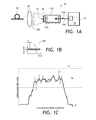
- FIG. 1A is a schematic view of a light source of the invention including a multimode laser diode
- FIG. 1B is a time trace of a driving current of the laser diode of FIG. 1A ;
- FIG. 1C is a time-averaged light intensity distribution on an end facet of the multimode laser diode of FIG. 1A with and without dithering;
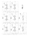
- FIG. 2 is the distributions of FIG. 1C at different dithering currents
- FIG. 3 is a difference between an ideally smooth distribution and the time-averaged distributions of FIG. 2 at the different dithering currents;
- FIG. 4 is a dependence of a peak intensity reduction due to the smoothing of the time-averaged light intensity distributions on the peak-to-peak amplitude of the dithering at the dc driving current of 12 A;
- FIG. 5 is a dependence of an average peak intensity reduction due to the smoothing of time-averaged light intensity distributions of 11 laser diodes on the peak-to-peak amplitude of the dithering at different values of the dc driving current;
- FIG. 6A is a schematic view of an embodiment of a light source of the invention including two laser diodes;
- FIG. 6B is a time trace of driving currents of the laser diodes of FIG. 6A ;
- FIG. 7A is a schematic view of an embodiment of a light source of the invention including four laser diodes;
- FIG. 7B is a time trace of driving currents of the laser diodes of FIG. 7A ;
- FIG. 8 is a flow chart of an exemplary method of operating a light source according to the invention.
- a light source 10 includes a first multimode laser diode 11 A having a first end facet 12 A for emitting first laser light 13 A, and a driver 14 coupled to the laser diode 11 A by a cable 19 A for providing a first dc driving current 15 A to the first multimode laser diode 11 A.
- the driver 14 includes a ditherer 16 for dithering the first driving current 15 A.
- the driving current 15 A has an amplitude I 0 of its dc component, and at a peak-to-peak amplitude ⁇ of its dithering component.
- the amplitude ⁇ of the dithering is high enough to periodically perturb a near-field light intensity or power density distribution 17 at the first end facet 12 A, thereby reducing a time-averaged local intensity of the first laser light 13 A at the first end facet 12 A.
- the time-averaged local intensity forms a distribution 18 .
- the near-field light intensity or power density distribution 17 without dithering, and the time-averaged local intensity or power density distribution 18 with dithering are better seen in FIG. 1C .
- the near-field light intensity distribution without dithering 17 is rich with small sharp peaks. It is obtained at the dc driving current of 12 Amperes.
- the time-averaged local intensity distribution with dithering 18 is obtained at the dc driving current amplitude I 0 of 12 A, and the peak-to-peak dithering amplitude ⁇ of 3030 mA, or 25%, at the frequency of 25 kHz, and the output power level of 11 W.
- the peak-to-peak dithering amplitude ⁇ is selected to be low enough to keep a time-domain modulation of the first laser light 13 A low, preferably under 25%, In many practical cases, the peak-to-peak amplitude of dithering is between 7% and 25% of the amplitude I 0 of the first driving current 15 A.
- a time period T of the dithered current 15 A is larger than a thermal time constant of the first multimode laser diode 11 A, so that the dithering will effectively modulate the temperature of the first multimode laser diode 11 A.
- the time period can be at least 150 microseconds.
- the driving profile can be triangular as shown in FIG. 1B for more uniform smoothing, or it can be sinusoidal or any other suitable shape.
- the peak intensity averaging is more efficient in multimode laser diodes having the front facet 12 A at least 50 micrometers wide. At the emission wavelength of between 800 nm and 1000 nm, more than 4-5 lateral optical modes are present at the 50 micrometers wide front facet 12 A. The more modes are present, the more efficient the smoothing action of the dithering generally becomes.
- the laser diode 10 has the width of the laser aperture 12 A of 100 micrometers and is driven at the dc current 15 A amplitude I 0 of 12 Amperes to produce 11 W of optical power.
- the horizontal axes denote the laser aperture 12 A width coordinate, and the vertical axes denote light intensity in arbitrary units.
- the distributions 21 , 22 , 23 , 24 , 25 , 26 , 27 , and 28 correspond to the peak-to-peak dithering amplitudes ⁇ of 30 mA, 180 mA, 330 mA, 780 mA, 1080 mA, 1530 mA, 2280 mA, and 3030 mA, respectively; or 0.25%; 1.5%; 2.75%; 6.5%; 9%; 12.75%; 19% and 25.3% of the dc current amplitude I 0 , respectively.
- the ratio of the dithering current amplitude ⁇ to the dc current amplitude I 0 increases, the time-averaged optical power distributions 21 to 28 become more and more smooth.
- FIG. 3 The smoothing effect is better seen in FIG. 3 , wherein differences 31 , 32 , 33 , 34 , 35 , 36 , 37 , and 38 between time-averaged 18 light intensity distributions 21 , 22 , 23 , 24 , 25 , 26 , 27 , and 28 of FIG. 2 , and an ideally smooth distribution, are shown for the same dithering current amplitudes ⁇ of 30 mA, 180 mA, 330 mA, 780 mA, 1080 mA, 1530 mA, 2280 mA, and 3030 mA, respectively.
- the horizontal axes denote the laser aperture width coordinate
- the vertical axes denote light intensity difference in arbitrary units.
- the light source 10 can be used to pump rare-earth doped laser rods and optical waveguides.
- the light source 10 in FIG. 1A is shown to include an optional rare-earth doped optical fiber 41 , for example erbium (Er) or ytterbium (Yb) doped fiber, which is optically coupled to the multimode laser diode 11 A via an optional coupling lens 42 .
- the multimode laser diode 11 A emits the laser light 13 A, which pumps the rare-earth doped optical fiber 41 .
- the dithering of the driving current 15 A allows one to extend the lifetime of the light source 10 by preserving the laser diode 11 A.
- the laser diode 11 A can lase in the 800 nm-1000 nm wavelength range.
- Such lasers frequently utilize GaAs—InAlGaAs material system including GaAs material.
- FIG. 4 a normalized root-mean-square (RMS) reduction of light intensity for the single laser diode 11 A is plotted vs. peak-to-peak dithering current amplitude 6 in percents, at the dithering frequency of 25 kHz, and the dc driving current amplitude I 0 of 12 A.
- RMS root-mean-square
- FIG. 5 a dependence of mean normalized RMS reduction is plotted at the dc driving current amplitude L of 12 Amperes (curve 51 ), 13 Amperes (curve 52 ), and 14.4 Amperes (curve 53 ).
- FIG. 5 shows mean values averaged over 11 diodes.
- a light source 60 is similar to the light source 10 of FIG. 1A .
- the light source 60 has not one but two multimode laser diodes, specifically the first laser diode 11 A and a second laser diode 11 B.
- the second laser diode has a second facet 12 B for emitting a second laser beam 13 B.
- a laser driver 64 is configured to provide not only the first 15 A but also a second 15 B dc driving current to the first 11 A and second 11 B multimode laser diodes, via cables 19 A and 19 B, respectively, or via other means such as a common cable, not shown.
- the first 13 A and second 13 B laser beams are collected by first 61 A and second 61 B fast-axis collimated cylindrical lenses, and is directed towards a slow-axis collimating lens 62 , which focuses the first 13 A and second 13 B laser beams into a multimode optical fiber 63 , to combine into light 65 emitted by the light source 60 .
- Other beam-combining optics including prisms or mirrors, can be used, as known to a person skilled in the art.
- the driver 64 includes a ditherer 66 configured for dithering the first 15 A and second 15 B driving currents.
- the first 15 A and second 15 B driving currents having amplitudes I 0A and I 0B are dithered at peak-to-peak amplitudes ⁇ A and ⁇ B , respectively, which are high enough to periodically perturb near-field light intensity distributions, not shown, at the first 12 A and second 12 B end facets, respectively, thereby reducing a time-averaged local intensity of the first 13 A and second 13 B laser light at the first 12 A and second 12 B end facets, respectively, as explained above on the example of the first laser diode 11 A with reference to FIG. 1C , FIG. 2 , and FIG. 3 .
- the dithering of the second driving current 15 B is in counter phase with the dithering of the first driving current 15 A. Due to the counter-phase dithering, the time domain modulation (TDM) i.e., variation in the emitted optical power of the first 13 A and second 13 B laser beams is also in counter-phase, and thus tend to cancel or at least partially compensate each other, lessening the TDM of the combined output light 65 of the light source 60 .
- TDM time domain modulation
- the dithering amplitudes ⁇ A and ⁇ B can be further increased to better average out sharp peaks in the near-field light intensity distributions of the laser diodes 11 A and 11 B, substantially without increasing TDM of the combined output light 65 of the light source 60 .
- the output multimode fiber 63 can be replaced with another waveguide optically coupled to the first 12 A and second 12 B end facets, or omitted entirely for free-space coupling to another optical element, such as an active laser fiber or a laser rod, to be pumped by the light source 60 .
- a light source 70 is similar to the light source 60 of FIG. 6A .
- the light source 70 includes not two but four multimode laser diodes 11 A, 11 B, 11 C, and 11 D having four facets 12 A, 12 B, 12 C, and 12 D, respectively, for emitting four laser beams 13 A, 13 B, 13 C, and 13 D, respectively.
- a laser driver 74 is configured to provide four driving currents 15 A, 15 B, 15 C, and 15 D to the multimode laser diodes 11 A, 11 B, 11 C, and 11 D, via cables 19 A, 19 B, 19 C, and 19 D, respectively, or via other means such as a common cable.
- FIG. 1 A laser driver 74 is configured to provide four driving currents 15 A, 15 B, 15 C, and 15 D to the multimode laser diodes 11 A, 11 B, 11 C, and 11 D, via cables 19 A, 19 B, 19 C, and 19 D, respectively, or via other means such as a common cable.
- the laser beams 13 A, 13 B, 13 C, and 13 D are collected by fast-axis collimated cylindrical lenses 61 A, 61 B, 61 C, and 61 D, and is directed towards a slow-axis collimating lens 72 , which focuses the laser beams 13 A to 13 D into a multimode optical fiber 73 , to combine the laser beams 13 A to 13 D into a light beam 75 emitted by the light source 70 .
- Other beam-combining optics, and/or other beam delivery waveguides can be used, as known to a person skilled in the art.
- the driver 74 includes a ditherer 76 configured for dithering the driving currents 15 A to 15 D.
- the four driving currents 15 A, 15 B, 15 C, and 15 D having amplitudes I 0A , I 0B , I 0C , and I 0D are dithered at peak-to-peak amplitudes ⁇ A , ⁇ B , ⁇ C , and ⁇ D , respectively, which are high enough to periodically perturb near-field light intensity distributions, not shown, at the four end facets 12 A, 12 B, 12 C, and 12 D, respectively, thereby reducing a time-averaged near-field light intensity of the laser beams 13 A to 13 D at the end facets 12 A to 12 D, respectively.
- the dithering of the second driving current 15 B is in counter phase with the dithering of the first driving current 15 A; the dithering of the fourth driving current 15 D is in counter phase with the dithering of the third driving current 15 C; and the dithering of the third 15 C and fourth 15 D driving currents is at 90 degrees phase shift with respect to the dithering of the first driving current 15 A. Due to the counter-phase dithering, the TDM of the first 13 A and second 13 B laser beams; and second 13 B and fourth 13 D laser beams is in counter-phase, and thus tends to cancel or at least partially compensate each other, lessening the TDM of the combined output light 75 of the light source 70 .
- a method 80 of operating a laser source is presented.
- the first dc driving current 15 A is applied to the first multimode laser diode 11 A to cause the first end facet 12 A to emit the first laser light 13 A.
- the first dc driving current 15 A is dithered.
- the peak-to-peak amplitude ⁇ of dithering of step 82 is selected to be high enough to periodically perturb the near-field light intensity distribution 17 at the first end facet 12 A, thereby reducing a time-averaged local intensity 18 of the first laser light 13 A at the first end facet 12 A.
- the peak-to-peak amplitude ⁇ of dithering is also low enough to keep a time-domain modulation of the light emitted by the light source under 25%, and more preferably under 7%. As explained above, it is preferable that the peak-to-peak amplitude of dithering be between 2% and 25% of the first dc driving current.
- a general goal is to modulate the driving current 15 A just enough to provide an appreciable, for example at least 15%, reduction of the averaged local peak intensity of the first laser light at the first end facet, with as little perturbation of the output optical power as practical.
- first laser diode 15 A be driven with the dithering provided by step 82 , to reduce a chance of catastrophic failure, especially at high currents.
- first laser diode 15 A can be driven with the dithering turned on at least for 10% of its expected lifetime. For a 10,000 hours of a lifetime, that means driving the first laser diode 15 A for at least 1000 hours.
- the first laser diode 15 A, once installed into the light source 10 of FIG. 1A is always driven with the dithering turned on.
- the next two steps of the method 80 are optional, being applicable to the light sources 60 of FIG. 6A and 70 of FIG. 7B .
- the second dc driving current 15 B is provided to the second multimode laser diode 11 B to cause its end facet 12 B to emit second laser light or beam 13 B.
- the second dc driving current 15 B is dithered in counter-phase with the first dc driving current 15 A dithered in step 82 .
- the peak-to-peak amplitude ⁇ of dithering of the second dc driving current 15 B is selected to be high enough to periodically perturb a near-field light intensity distribution at the second end facet 12 B, thereby reducing a time-averaged local intensity of the second laser light 13 B at the second end facet 12 B.
- next two steps of the method 80 are optional, being applicable to the light source 70 of FIG. 7B .
- the third 15 C and fourth 15 D dc driving currents are applied to the third 11 C and fourth 11 D multimode laser diodes, respectively, to cause their respective end facets 12 C and 12 D to emit third and fourth laser beams 13 C and 13 D, respectively.
- the third and fourth dc driving currents 15 C and 15 D are dithered in counter-phase with respect to each other and at 90 degrees (in quadrature) with respect to the first dc driving current 15 A dithered in the step 82 .
- the amplitudes ⁇ of dithering of the third and fourth dc driving currents 15 C and 15 D are selected to be high enough to periodically perturb near-field light intensity distributions at the third 12 C and fourth 12 D end facets, thereby reducing averaged local peak intensities of the third 13 C and fourth 13 D laser beams at the third 12 C and fourth 12 D end facets, respectively.
Abstract
Description
Claims (20)
Priority Applications (1)
| Application Number | Priority Date | Filing Date | Title |
|---|---|---|---|
| US14/042,094 US8948222B1 (en) | 2013-09-30 | 2013-09-30 | Laser diode light source |
Applications Claiming Priority (1)
| Application Number | Priority Date | Filing Date | Title |
|---|---|---|---|
| US14/042,094 US8948222B1 (en) | 2013-09-30 | 2013-09-30 | Laser diode light source |
Publications (1)
| Publication Number | Publication Date |
|---|---|
| US8948222B1 true US8948222B1 (en) | 2015-02-03 |
Family
ID=52395733
Family Applications (1)
| Application Number | Title | Priority Date | Filing Date |
|---|---|---|---|
| US14/042,094 Active US8948222B1 (en) | 2013-09-30 | 2013-09-30 | Laser diode light source |
Country Status (1)
| Country | Link |
|---|---|
| US (1) | US8948222B1 (en) |
Cited By (1)
| Publication number | Priority date | Publication date | Assignee | Title |
|---|---|---|---|---|
| US20180013257A1 (en) * | 2015-01-20 | 2018-01-11 | Nam Seong Kim | Highly efficient laser ignition device |
Citations (14)
| Publication number | Priority date | Publication date | Assignee | Title |
|---|---|---|---|---|
| US4656638A (en) | 1983-02-14 | 1987-04-07 | Xerox Corporation | Passivation for surfaces and interfaces of semiconductor laser facets or the like |
| US5144634A (en) | 1989-09-07 | 1992-09-01 | International Business Machines Corporation | Method for mirror passivation of semiconductor laser diodes |
| US5473625A (en) * | 1994-09-26 | 1995-12-05 | At&T Corp. | Tunable distributed Bragg reflector laser for wavelength dithering |
| US5477368A (en) * | 1994-12-29 | 1995-12-19 | At&T Corp. | High power lightwave transmitter using highly saturated amplifier for residual AM suppression |
| US6208678B1 (en) | 1998-11-24 | 2001-03-27 | Nortel Networks Limited | Laser pump source and method of operation thereof |
| US6317235B1 (en) | 1998-08-28 | 2001-11-13 | Zilog, Inc. | Method and system for preventing burn-out of infrared transmitter diodes |
| US6331908B1 (en) * | 1999-11-22 | 2001-12-18 | Lucent Technologies Inc. | Optical system for reduced SBS |
| US20020163945A1 (en) | 2001-03-16 | 2002-11-07 | Bongsin Kwark | Modulation current compensation of laser for controlled extinction ratio using dither signal |
| US6678303B2 (en) | 2001-06-22 | 2004-01-13 | Fuji Photo Film Co., Ltd. | Semiconductor laser device in which end of electric-to-optical conversion layer protrudes outward from shortest current path between end facets of cladding layers |
| US7065117B2 (en) | 2001-12-25 | 2006-06-20 | Fuji Photo Film Co., Ltd. | Semiconductor laser element having end-facet protection layer which includes unoxidized or unnitrided first sublayer formed on end facet and second sublayer produced by oxidizing or nitriding the surface of the first sublayer |
| WO2007000615A2 (en) | 2005-06-28 | 2007-01-04 | Bookham Technology Plc | High power semiconductor laser diode |
| US20080273563A1 (en) | 2005-11-21 | 2008-11-06 | Berthold Schmidt | High Power Semiconductor Laser Diode |
| US20090180500A1 (en) | 2007-10-23 | 2009-07-16 | Ipg Photonics Corporation | Method and device for controlling optical output of laser diode |
| US8319249B2 (en) | 2008-09-30 | 2012-11-27 | Lg Innotek Co., Ltd. | Semiconductor light emitting device |
-
2013
- 2013-09-30 US US14/042,094 patent/US8948222B1/en active Active
Patent Citations (15)
| Publication number | Priority date | Publication date | Assignee | Title |
|---|---|---|---|---|
| US4656638A (en) | 1983-02-14 | 1987-04-07 | Xerox Corporation | Passivation for surfaces and interfaces of semiconductor laser facets or the like |
| US5144634A (en) | 1989-09-07 | 1992-09-01 | International Business Machines Corporation | Method for mirror passivation of semiconductor laser diodes |
| US5473625A (en) * | 1994-09-26 | 1995-12-05 | At&T Corp. | Tunable distributed Bragg reflector laser for wavelength dithering |
| US5477368A (en) * | 1994-12-29 | 1995-12-19 | At&T Corp. | High power lightwave transmitter using highly saturated amplifier for residual AM suppression |
| US6317235B1 (en) | 1998-08-28 | 2001-11-13 | Zilog, Inc. | Method and system for preventing burn-out of infrared transmitter diodes |
| US6208678B1 (en) | 1998-11-24 | 2001-03-27 | Nortel Networks Limited | Laser pump source and method of operation thereof |
| US6331908B1 (en) * | 1999-11-22 | 2001-12-18 | Lucent Technologies Inc. | Optical system for reduced SBS |
| US20020163945A1 (en) | 2001-03-16 | 2002-11-07 | Bongsin Kwark | Modulation current compensation of laser for controlled extinction ratio using dither signal |
| US6678303B2 (en) | 2001-06-22 | 2004-01-13 | Fuji Photo Film Co., Ltd. | Semiconductor laser device in which end of electric-to-optical conversion layer protrudes outward from shortest current path between end facets of cladding layers |
| US7065117B2 (en) | 2001-12-25 | 2006-06-20 | Fuji Photo Film Co., Ltd. | Semiconductor laser element having end-facet protection layer which includes unoxidized or unnitrided first sublayer formed on end facet and second sublayer produced by oxidizing or nitriding the surface of the first sublayer |
| WO2007000615A2 (en) | 2005-06-28 | 2007-01-04 | Bookham Technology Plc | High power semiconductor laser diode |
| US20100189152A1 (en) | 2005-06-28 | 2010-07-29 | Bookham Technology Plc | High power semiconductor laser diode |
| US20080273563A1 (en) | 2005-11-21 | 2008-11-06 | Berthold Schmidt | High Power Semiconductor Laser Diode |
| US20090180500A1 (en) | 2007-10-23 | 2009-07-16 | Ipg Photonics Corporation | Method and device for controlling optical output of laser diode |
| US8319249B2 (en) | 2008-09-30 | 2012-11-27 | Lg Innotek Co., Ltd. | Semiconductor light emitting device |
Cited By (2)
| Publication number | Priority date | Publication date | Assignee | Title |
|---|---|---|---|---|
| US20180013257A1 (en) * | 2015-01-20 | 2018-01-11 | Nam Seong Kim | Highly efficient laser ignition device |
| US10554009B2 (en) * | 2015-01-20 | 2020-02-04 | Nam Seong Kim | Highly efficient laser ignition device |
Similar Documents
| Publication | Publication Date | Title |
|---|---|---|
| Nagai et al. | High‐power, high‐efficiency 1.3 μm superluminescent diode with a buried bent absorbing guide structure | |
| US10534128B2 (en) | Pulsed laser device | |
| US10971897B2 (en) | Semiconductor laser device, semiconductor laser module, and laser light source system for welding | |
| JP2009295680A (en) | Semiconductor laser device | |
| US8693514B2 (en) | Pulse generation method and laser light source apparatus | |
| EP1243055A2 (en) | Semiconductor laser element having a diverging region | |
| US10439361B2 (en) | Semiconductor laser device and laser light irradiation apparatus | |
| US20230231629A1 (en) | Light source, light source device, method of driving light source, raman amplifier, and raman amplification system | |
| Adachi et al. | 100° C, 25 Gbit/s direct modulation of 1.3 µm surface emitting laser | |
| US8948222B1 (en) | Laser diode light source | |
| US20100284435A1 (en) | Red-Shifted Optical Feedback Laser | |
| Yamagata et al. | Performance and reliability of high power, high brightness 8xx-9xx nm semiconductor laser diodes | |
| US20040057485A1 (en) | Semiconductor laser device, semiconductor laser module, and optical fiber amplifier | |
| JP2021525962A (en) | Large Optical Resonator (LOC) Laser Diode with Quantum Well Offset and Efficient Single Mode Laser Emission Along the Fast Axis | |
| US7194014B2 (en) | Semiconductor laser device, semiconductor laser module, and optical fiber amplifier using the semiconductor laser module | |
| Kelemen et al. | High-brightness 1040-nm tapered diode lasers | |
| US20110206082A1 (en) | Semiconductor laser and semiconductor laser module | |
| EP2661794B1 (en) | Method for stabilizing optical output power of fiber laser | |
| JP2002374037A (en) | Semiconductor laser module, fiber-optic amplifier using the same and optical communication system | |
| KR20060089740A (en) | Surface-emitting semiconductor laser comprising a structured waveguide | |
| JP2007227723A (en) | Device and controlling method for variable-wavelength light source | |
| KR100731687B1 (en) | Laser diode and manufacturing method thereof | |
| KR100848759B1 (en) | Semiconductor laser diode chip having a plurality of waveguide | |
| Zibik et al. | Novel single-mode fiber coupled broadband seed source for pulsed fiber laser systems | |
| WO2003100930A1 (en) | Laser module |
Legal Events
| Date | Code | Title | Description |
|---|---|---|---|
| AS | Assignment |
Owner name: JDS UNIPHASE CORPORATION, CALIFORNIA Free format text: ASSIGNMENT OF ASSIGNORS INTEREST;ASSIGNORS:VENABLES, DAVID;ZUCKER, ERIK PAUL;ROSSIN, VICTOR;AND OTHERS;SIGNING DATES FROM 20130924 TO 20130926;REEL/FRAME:031312/0072 |
|
| STCF | Information on status: patent grant |
Free format text: PATENTED CASE |
|
| AS | Assignment |
Owner name: LUMENTUM OPERATIONS LLC, CALIFORNIA Free format text: ASSIGNMENT OF ASSIGNORS INTEREST;ASSIGNOR:JDS UNIPHASE CORPORATION;REEL/FRAME:036420/0340 Effective date: 20150731 |
|
| FEPP | Fee payment procedure |
Free format text: PAYOR NUMBER ASSIGNED (ORIGINAL EVENT CODE: ASPN); ENTITY STATUS OF PATENT OWNER: LARGE ENTITY |
|
| AS | Assignment |
Owner name: LUMENTUM OPERATIONS LLC, CALIFORNIA Free format text: CORRECTIVE ASSIGNMENT TO CORRECT THE PATENTS LISTED ON PAGE A-A33 PREVIOUSLY RECORDED ON REEL 036420 FRAME 0340. ASSIGNOR(S) HEREBY CONFIRMS THE PATENT NUMBERS 7,868,247 AND 6,476,312 WERE LISTED IN ERROR AND SHOULD BE REMOVED;ASSIGNOR:JDS UNIPHASE CORPORATION;REEL/FRAME:037562/0513 Effective date: 20150731 Owner name: LUMENTUM OPERATIONS LLC, CALIFORNIA Free format text: CORRECTIVE ASSIGNMENT TO CORRECT INCORRECT PATENTS 7,868,247 AND 6,476,312 ON PAGE A-A33 PREVIOUSLY RECORDED ON REEL 036420 FRAME 0340. ASSIGNOR(S) HEREBY CONFIRMS THE ASSIGNMENT;ASSIGNOR:JDS UNIPHASE CORPORATION;REEL/FRAME:037562/0513 Effective date: 20150731 |
|
| AS | Assignment |
Owner name: LUMENTUM OPERATIONS LLC, CALIFORNIA Free format text: CORRECTIVE ASSIGNMENT TO CORRECT THE PATENTS LISTED ON PAGE A-A33 PATENT NUMBERS 7,868,247 AND 6,476,312 WERE LISTED IN ERROR AND SHOULD BE REMOVED. PREVIOUSLY RECORDED ON REEL 036420 FRAME 0340. ASSIGNOR(S) HEREBY CONFIRMS THE ASSIGNMENT;ASSIGNOR:JDS UNIPHASE CORPORATION;REEL/FRAME:037627/0641 Effective date: 20150731 Owner name: LUMENTUM OPERATIONS LLC, CALIFORNIA Free format text: CORRECTIVE ASSIGNMENT TO CORRECT PATENTS 7,868,247 AND 6,476,312 LISTED ON PAGE A-A33 PREVIOUSLY RECORDED ON REEL 036420 FRAME 0340. ASSIGNOR(S) HEREBY CONFIRMS THE ASSIGNMENT;ASSIGNOR:JDS UNIPHASE CORPORATION;REEL/FRAME:037627/0641 Effective date: 20150731 |
|
| MAFP | Maintenance fee payment |
Free format text: PAYMENT OF MAINTENANCE FEE, 4TH YEAR, LARGE ENTITY (ORIGINAL EVENT CODE: M1551) Year of fee payment: 4 |
|
| AS | Assignment |
Owner name: DEUTSCHE BANK AG NEW YORK BRANCH, AS COLLATERAL AGENT, NEW YORK Free format text: PATENT SECURITY AGREEMENT;ASSIGNORS:LUMENTUM OPERATIONS LLC;OCLARO FIBER OPTICS, INC.;OCLARO, INC.;REEL/FRAME:047788/0511 Effective date: 20181210 Owner name: DEUTSCHE BANK AG NEW YORK BRANCH, AS COLLATERAL AG Free format text: PATENT SECURITY AGREEMENT;ASSIGNORS:LUMENTUM OPERATIONS LLC;OCLARO FIBER OPTICS, INC.;OCLARO, INC.;REEL/FRAME:047788/0511 Effective date: 20181210 |
|
| AS | Assignment |
Owner name: OCLARO, INC., CALIFORNIA Free format text: RELEASE BY SECURED PARTY;ASSIGNOR:DEUTSCHE AG NEW YORK BRANCH;REEL/FRAME:051287/0556 Effective date: 20191212 Owner name: OCLARO FIBER OPTICS, INC., CALIFORNIA Free format text: RELEASE BY SECURED PARTY;ASSIGNOR:DEUTSCHE AG NEW YORK BRANCH;REEL/FRAME:051287/0556 Effective date: 20191212 Owner name: LUMENTUM OPERATIONS LLC, CALIFORNIA Free format text: RELEASE BY SECURED PARTY;ASSIGNOR:DEUTSCHE AG NEW YORK BRANCH;REEL/FRAME:051287/0556 Effective date: 20191212 |
|
| MAFP | Maintenance fee payment |
Free format text: PAYMENT OF MAINTENANCE FEE, 8TH YEAR, LARGE ENTITY (ORIGINAL EVENT CODE: M1552); ENTITY STATUS OF PATENT OWNER: LARGE ENTITY Year of fee payment: 8 |