US8961439B2 - System and method for analyzing gait using fabric sensors - Google Patents
System and method for analyzing gait using fabric sensors Download PDFInfo
- Publication number
- US8961439B2 US8961439B2 US13/412,286 US201213412286A US8961439B2 US 8961439 B2 US8961439 B2 US 8961439B2 US 201213412286 A US201213412286 A US 201213412286A US 8961439 B2 US8961439 B2 US 8961439B2
- Authority
- US
- United States
- Prior art keywords
- gait
- sensor
- sensors
- sock
- signal
- Prior art date
- Legal status (The legal status is an assumption and is not a legal conclusion. Google has not performed a legal analysis and makes no representation as to the accuracy of the status listed.)
- Active - Reinstated, expires
Links
- 230000005021 gait Effects 0.000 title claims abstract description 147
- 238000000034 method Methods 0.000 title claims description 37
- 239000004744 fabric Substances 0.000 title description 14
- 230000033001 locomotion Effects 0.000 claims abstract description 43
- 239000004753 textile Substances 0.000 claims abstract description 29
- 238000004458 analytical method Methods 0.000 claims description 96
- 238000005452 bending Methods 0.000 claims description 38
- 230000008859 change Effects 0.000 claims description 31
- 230000001133 acceleration Effects 0.000 claims description 30
- 239000004020 conductor Substances 0.000 claims description 27
- 210000000629 knee joint Anatomy 0.000 claims description 14
- 239000003990 capacitor Substances 0.000 claims description 13
- 238000006073 displacement reaction Methods 0.000 claims description 10
- 210000004394 hip joint Anatomy 0.000 claims description 9
- 230000008569 process Effects 0.000 claims description 9
- 239000000463 material Substances 0.000 claims description 8
- 210000002683 foot Anatomy 0.000 description 154
- 210000003127 knee Anatomy 0.000 description 82
- 238000010586 diagram Methods 0.000 description 56
- 230000036544 posture Effects 0.000 description 33
- 210000002414 leg Anatomy 0.000 description 18
- 230000005540 biological transmission Effects 0.000 description 17
- 230000005484 gravity Effects 0.000 description 15
- 229910001220 stainless steel Inorganic materials 0.000 description 9
- 210000003813 thumb Anatomy 0.000 description 8
- 210000004247 hand Anatomy 0.000 description 7
- 210000003371 toe Anatomy 0.000 description 7
- 230000000694 effects Effects 0.000 description 6
- 238000005516 engineering process Methods 0.000 description 6
- 210000001624 hip Anatomy 0.000 description 6
- 230000004044 response Effects 0.000 description 6
- 0 C[C@@](C1)C(CC2CCCC2)[C@@]1C1=C(CCC2CCCC2)C=C1CCCCC(C1N)C=C(C)C1[C@](C1)C(CCC2CCCC2)[C@@](*)C1C1CCCC1 Chemical compound C[C@@](C1)C(CC2CCCC2)[C@@]1C1=C(CCC2CCCC2)C=C1CCCCC(C1N)C=C(C)C1[C@](C1)C(CCC2CCCC2)[C@@](*)C1C1CCCC1 0.000 description 5
- 230000009471 action Effects 0.000 description 5
- 238000006243 chemical reaction Methods 0.000 description 5
- 230000035790 physiological processes and functions Effects 0.000 description 5
- 230000002618 waking effect Effects 0.000 description 5
- 230000006399 behavior Effects 0.000 description 4
- 210000001503 joint Anatomy 0.000 description 4
- 238000012544 monitoring process Methods 0.000 description 4
- 230000001360 synchronised effect Effects 0.000 description 4
- 230000009194 climbing Effects 0.000 description 3
- 239000006260 foam Substances 0.000 description 3
- 230000036541 health Effects 0.000 description 3
- 230000001939 inductive effect Effects 0.000 description 3
- 230000003993 interaction Effects 0.000 description 3
- 230000007659 motor function Effects 0.000 description 3
- 230000035479 physiological effects, processes and functions Effects 0.000 description 3
- 229920001296 polysiloxane Polymers 0.000 description 3
- 238000012545 processing Methods 0.000 description 3
- 230000029058 respiratory gaseous exchange Effects 0.000 description 3
- 230000002123 temporal effect Effects 0.000 description 3
- 238000012360 testing method Methods 0.000 description 3
- RYGMFSIKBFXOCR-UHFFFAOYSA-N Copper Chemical compound [Cu] RYGMFSIKBFXOCR-UHFFFAOYSA-N 0.000 description 2
- XEEYBQQBJWHFJM-UHFFFAOYSA-N Iron Chemical compound [Fe] XEEYBQQBJWHFJM-UHFFFAOYSA-N 0.000 description 2
- 241001465754 Metazoa Species 0.000 description 2
- 208000018737 Parkinson disease Diseases 0.000 description 2
- 229920002334 Spandex Polymers 0.000 description 2
- PPBRXRYQALVLMV-UHFFFAOYSA-N Styrene Chemical compound C=CC1=CC=CC=C1 PPBRXRYQALVLMV-UHFFFAOYSA-N 0.000 description 2
- 229910052770 Uranium Inorganic materials 0.000 description 2
- 230000002159 abnormal effect Effects 0.000 description 2
- 210000000544 articulatio talocruralis Anatomy 0.000 description 2
- 210000001099 axilla Anatomy 0.000 description 2
- 230000008901 benefit Effects 0.000 description 2
- 239000008280 blood Substances 0.000 description 2
- 210000004369 blood Anatomy 0.000 description 2
- 230000036760 body temperature Effects 0.000 description 2
- 230000037396 body weight Effects 0.000 description 2
- 238000004891 communication Methods 0.000 description 2
- 230000000994 depressogenic effect Effects 0.000 description 2
- 238000013461 design Methods 0.000 description 2
- 238000001514 detection method Methods 0.000 description 2
- 238000007599 discharging Methods 0.000 description 2
- 208000014674 injury Diseases 0.000 description 2
- 230000002452 interceptive effect Effects 0.000 description 2
- 230000007774 longterm Effects 0.000 description 2
- 239000000696 magnetic material Substances 0.000 description 2
- 238000005259 measurement Methods 0.000 description 2
- 239000007769 metal material Substances 0.000 description 2
- 210000001872 metatarsal bone Anatomy 0.000 description 2
- 230000000737 periodic effect Effects 0.000 description 2
- 238000000819 phase cycle Methods 0.000 description 2
- 238000005381 potential energy Methods 0.000 description 2
- 238000007781 pre-processing Methods 0.000 description 2
- 238000012552 review Methods 0.000 description 2
- 239000004759 spandex Substances 0.000 description 2
- 210000004243 sweat Anatomy 0.000 description 2
- 238000013519 translation Methods 0.000 description 2
- 238000011282 treatment Methods 0.000 description 2
- 238000002604 ultrasonography Methods 0.000 description 2
- 206010000117 Abnormal behaviour Diseases 0.000 description 1
- 208000012260 Accidental injury Diseases 0.000 description 1
- 208000024827 Alzheimer disease Diseases 0.000 description 1
- DCEHVBLXWODXCW-UHFFFAOYSA-N CCC(C)C1CCCC1 Chemical compound CCC(C)C1CCCC1 DCEHVBLXWODXCW-UHFFFAOYSA-N 0.000 description 1
- OKTJSMMVPCPJKN-UHFFFAOYSA-N Carbon Chemical compound [C] OKTJSMMVPCPJKN-UHFFFAOYSA-N 0.000 description 1
- 229920000742 Cotton Polymers 0.000 description 1
- 241000282326 Felis catus Species 0.000 description 1
- 208000014770 Foot disease Diseases 0.000 description 1
- 208000017899 Foot injury Diseases 0.000 description 1
- 241000282412 Homo Species 0.000 description 1
- 206010061225 Limb injury Diseases 0.000 description 1
- BQCADISMDOOEFD-UHFFFAOYSA-N Silver Chemical compound [Ag] BQCADISMDOOEFD-UHFFFAOYSA-N 0.000 description 1
- 208000006011 Stroke Diseases 0.000 description 1
- 208000027418 Wounds and injury Diseases 0.000 description 1
- 210000003423 ankle Anatomy 0.000 description 1
- QVGXLLKOCUKJST-UHFFFAOYSA-N atomic oxygen Chemical compound [O] QVGXLLKOCUKJST-UHFFFAOYSA-N 0.000 description 1
- 230000003542 behavioural effect Effects 0.000 description 1
- -1 blood pressure Chemical compound 0.000 description 1
- 230000036772 blood pressure Effects 0.000 description 1
- 210000004556 brain Anatomy 0.000 description 1
- 239000003575 carbonaceous material Substances 0.000 description 1
- 206010008129 cerebral palsy Diseases 0.000 description 1
- 238000001816 cooling Methods 0.000 description 1
- 238000012937 correction Methods 0.000 description 1
- 230000008878 coupling Effects 0.000 description 1
- 238000010168 coupling process Methods 0.000 description 1
- 238000005859 coupling reaction Methods 0.000 description 1
- 230000006378 damage Effects 0.000 description 1
- 230000003247 decreasing effect Effects 0.000 description 1
- 230000007547 defect Effects 0.000 description 1
- 238000003745 diagnosis Methods 0.000 description 1
- 238000009826 distribution Methods 0.000 description 1
- 230000035622 drinking Effects 0.000 description 1
- 239000003814 drug Substances 0.000 description 1
- 210000005069 ears Anatomy 0.000 description 1
- 210000004177 elastic tissue Anatomy 0.000 description 1
- 210000001513 elbow Anatomy 0.000 description 1
- 230000005520 electrodynamics Effects 0.000 description 1
- 238000002474 experimental method Methods 0.000 description 1
- 230000004907 flux Effects 0.000 description 1
- 229910002804 graphite Inorganic materials 0.000 description 1
- 239000010439 graphite Substances 0.000 description 1
- 210000001255 hallux Anatomy 0.000 description 1
- 238000010438 heat treatment Methods 0.000 description 1
- 230000001771 impaired effect Effects 0.000 description 1
- 230000010354 integration Effects 0.000 description 1
- 229910052742 iron Inorganic materials 0.000 description 1
- 230000001788 irregular Effects 0.000 description 1
- 210000004936 left thumb Anatomy 0.000 description 1
- 238000012417 linear regression Methods 0.000 description 1
- 238000004519 manufacturing process Methods 0.000 description 1
- 239000002184 metal Substances 0.000 description 1
- 229910052751 metal Inorganic materials 0.000 description 1
- 210000003205 muscle Anatomy 0.000 description 1
- 230000000399 orthopedic effect Effects 0.000 description 1
- 229910052760 oxygen Inorganic materials 0.000 description 1
- 239000001301 oxygen Substances 0.000 description 1
- 239000002245 particle Substances 0.000 description 1
- 230000010399 physical interaction Effects 0.000 description 1
- 238000003825 pressing Methods 0.000 description 1
- 230000002441 reversible effect Effects 0.000 description 1
- 210000000614 rib Anatomy 0.000 description 1
- 238000005096 rolling process Methods 0.000 description 1
- 238000005070 sampling Methods 0.000 description 1
- 230000036421 sense of balance Effects 0.000 description 1
- 238000001228 spectrum Methods 0.000 description 1
- 239000010935 stainless steel Substances 0.000 description 1
- 238000003860 storage Methods 0.000 description 1
- 230000009182 swimming Effects 0.000 description 1
- 238000010998 test method Methods 0.000 description 1
- 238000012549 training Methods 0.000 description 1
- 210000000689 upper leg Anatomy 0.000 description 1
- 230000000007 visual effect Effects 0.000 description 1
Images


Classifications
-
- A—HUMAN NECESSITIES
- A61—MEDICAL OR VETERINARY SCIENCE; HYGIENE
- A61B—DIAGNOSIS; SURGERY; IDENTIFICATION
- A61B5/00—Measuring for diagnostic purposes; Identification of persons
- A61B5/103—Detecting, measuring or recording devices for testing the shape, pattern, colour, size or movement of the body or parts thereof, for diagnostic purposes
- A61B5/1036—Measuring load distribution, e.g. podologic studies
- A61B5/1038—Measuring plantar pressure during gait
-
- A—HUMAN NECESSITIES
- A61—MEDICAL OR VETERINARY SCIENCE; HYGIENE
- A61B—DIAGNOSIS; SURGERY; IDENTIFICATION
- A61B5/00—Measuring for diagnostic purposes; Identification of persons
- A61B5/68—Arrangements of detecting, measuring or recording means, e.g. sensors, in relation to patient
- A61B5/6801—Arrangements of detecting, measuring or recording means, e.g. sensors, in relation to patient specially adapted to be attached to or worn on the body surface
- A61B5/6802—Sensor mounted on worn items
- A61B5/6804—Garments; Clothes
- A61B5/6807—Footwear
-
- A—HUMAN NECESSITIES
- A61—MEDICAL OR VETERINARY SCIENCE; HYGIENE
- A61B—DIAGNOSIS; SURGERY; IDENTIFICATION
- A61B5/00—Measuring for diagnostic purposes; Identification of persons
- A61B5/103—Detecting, measuring or recording devices for testing the shape, pattern, colour, size or movement of the body or parts thereof, for diagnostic purposes
- A61B5/11—Measuring movement of the entire body or parts thereof, e.g. head or hand tremor, mobility of a limb
- A61B5/112—Gait analysis
Definitions
- Embodiments of the present invention can be applied to rehabilitation, physical training, long-term care, orthopedic and sports medicine, health, entertainment and other fields.
- Embodiments of the present invention relate to a system and a method for sensing and analyzing the wearer's foot movements and understanding the physiological state of the wearer by using textile sensor being fixed to the clothing.
- Gait analysis is commonly used to help athletes and patients with impaired motor function, such as patients with cerebral palsy, Parkinson's disease, stroke or accidental injury. Gait analysis of existing technologies is often conducted in specialized laboratories or physicians' consulting rooms and can only be completed by using many sophisticated devices and complex methods. However, the optimal gait analysis system should be able to achieve continuous real time monitoring at low cost and easy to operate and obtain. Existing technology has another defect: it cannot reflect the motor function of the user in the daily life. Therefore, experts and patients need a low-cost system to achieve quantitative and reproducible results. Gait analysis is currently mostly used to help athletes and the injured which is mainly conducted in laboratories or physicians' consulting rooms through visual observation. Clinicians rely on a wide range of gait analysis, diagnosis and treatment, but are facing many complex factors. Gait analysis systems and procedures for general users have the benefits of continuous monitoring, low price and easy to use and obtain. However, the traditional gait analysis equipment usually requires field tests, or comprehensive gait analysis experiments in laboratories, which goes against the popularity of gait analysis system.
- U.S. Pat. No. 6,984,208 discloses a method of testing user's posture and movement states with ultrasound and analyzing related data of gait analysis.
- ultrasound equipment is rather expensive, it is not conducive to the promotion of gait analysis system.
- U.S. patent No. 20080108913A1 discloses a method of detecting the user's fall with pressure sensor.
- each shoe or sock has to be equipped with an independent power supply, but not digital sensor.
- signal processing feedback method has to be adopted for signal analysis. The process is too cumbersome, lengthy and complex and needs to use fuzzy logics for preventing falls.
- the system can neither show the user's gait parameters nor sense the body posture or movement.
- accelerometer can be used for measuring the gait speed, stride length and gait time.
- Feedback value is no longer needed.
- Sock sensors may directly calculate the gait parameters or body posture and movement.
- U.S. patent No. US20090012433A1 discloses a method of detecting user's gait parameters with cameras, microphones and a sensor and analyzing relevant data. However, the analysis method is too cumbersome and not conducive to the promotion of gait analysis.
- U.S. patent No. US200610282021A1 discloses a method of detecting user's posture and gait with a sensor and a remote monitoring system and analyzing relevant data. However, the system has distance constraints. The monitor cannot process the relevant information when the user is too far away from it.
- U.S. patent No. US2007/0112287 A1 discloses a method of handing accelerometers and gyroscopes on the ears of users so as to detect the gait analysis data of users. However, too high cost is not conducive to the promotion.
- sensor is set in socks and thus comfortable and washable. Relevant data for gait analysis may be measured even a user wears different shoes. It is suitable for different users because socks have no such accurate size requirements as shoes. Instead, socks can completely fit the feet of users and obtain more accurate gait analysis results.
- the sock sensor in embodiments of the present invention may sense different shoes a user wears when he is walking and learn the style of shoes with the aid of gait analysis signal, such as high heels, low cutters, slippers, sneakers and skating shoes etc.
- Embodiments of the present invention sock sensor can be configured in different shoes and is easy to use for users and ergonomic.
- the sock sensors can be applied in a variety of shoes.
- An objective of the present invention is to sense gait analysis and posture changes, such as angle of bending of knee joint, stride length, the number of steps per minute and walking speed and if the heel is upon the earth or not, arms are swinging or not and the waist is bent or not with sensors in clothes and pants besides sensors in socks. Sequence and cycle of changes of various postures and other parameters are used to observe the health condition or rehabilitation treatment effects of users, or determine the posture of users (such as walking forward, walking backward, running, climbing stairs, walking down the stairs, climbing up, climbing down hill, walking sideways, falling).
- the invention may be used as an input of interactive computer games, other than just virtual computer games in which the player shows no actual interactive action with the game software.
- Embodiments of the present invention relate to a wearable gait analysis system with the following structure characteristics: first, the gait analysis device is wearable and comfortable and can be installed directly on general pants or socks and thus rather convenient in daily life; second, using wireless transmission technology, the user will not be disturbed in test; third, the wearable gait analysis system has the following features: washable, durable, elastic, flexible and squeezable, thus being convenient for use in daily life; fourth, with digital output and Bluetooth interfaces, the measured data can be sent directly to common instruments in daily life for signal analysis, such as PDA or notebook computer.
- Such electronic devices that can be easily obtained may be used for testing a user's posture and relevant data for gait analysis and the variability and stability of each parameter can also be presented with Power Spectrum; and fifth, the user's body weight and changes could be detected.
- Another objective of the present invention is, another reference area is set in the surrounding area where the transmission line is not insulated for detecting leakage of fabrics, for example, the fabric is wet or the transmission line and the reference area suffer from short circuit.
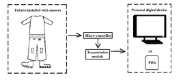
- FIG. 1 illustrates a block diagram of a gait analysis system using textile sensors in accordance with one embodiment of the present invention.
- FIG. 2 illustrates a sensor block diagram of first preferred embodiment of a gait analysis system using textile sensors in accordance with one embodiment of the present invention.
- FIG. 3A illustrates a location plan of a sensor in a sock in accordance with one embodiment of the present invention.
- FIG. 3B illustrates a relative location plan of a sensor in a sock in accordance with one embodiment of the present invention.
- FIG. 4A illustrates a location plan of a sensor on a knee in accordance with one embodiment of the present invention.
- FIG. 4B illustrates a location plan of a tension sensor being installed in pants in accordance with one embodiment of the present invention.
- FIG. 5 illustrates a typical timing sequence diagram and sensor location plan in accordance with one embodiment of the present invention.
- FIG. 6 illustrates a diagram of the first four phases in analysis of gait phase in accordance with one embodiment of the present invention.
- FIG. 7 illustrates a diagram of the last three phases in analysis of gait phase in accordance with one embodiment of the present invention.
- FIG. 8A illustrates a gait analysis diagram after completion in accordance with one embodiment of the present invention.
- FIG. 8B illustrates a method flow chart of phase of gait in accordance with one embodiment of the present invention.
- FIG. 9 illustrates a diagram used for analysis of temporal parameters in accordance with one embodiment of the present invention.
- FIG. 10A illustrates an analysis chart about the pressure center in normal walking.
- FIG. 10B illustrates an analysis chart about the mass center in normal walking.
- FIG. 10C illustrate a sagittal and horizontal view of the center of mass during walking
- FIG. 10D illustrates an analysis chart about the pressure center and mass center during going upstairs.
- FIG. 10E illustrates an analysis chart about the pressure center and mass center during running
- FIG. 10F illustrates an analysis chart about the pressure center and mass center during going downstairs in accordance with one embodiment of the present invention.
- FIG. 11 illustrates a timing sequence diagram of gait during running in accordance with one embodiment of the present invention.
- FIG. 12 illustrates a timing sequence diagram of gait during waking forward in accordance with one embodiment of the present invention.
- FIG. 13 illustrates a timing sequence diagram of gait during waking backward in accordance with one embodiment of the present invention.
- FIG. 14 illustrates a timing sequence diagram of gait during going upstairs in accordance with one embodiment of the present invention.
- FIG. 15 illustrates a timing sequence diagram of gait during going downstairs in accordance with one embodiment of the present invention.
- FIG. 16 illustrates a diagram of the first sock sensing system in accordance with one embodiment of the present invention.
- FIG. 17 illustrates a diagram of the second sock sensing system in accordance with one embodiment of the present invention.
- FIG. 18 illustrates a diagram of the third sock sensing system in accordance with one embodiment of the present invention.
- FIG. 19A illustrates a circuit diagram of installing a resistor next to the sensor and connecting in parallel.
- FIG. 19B illustrates a circuit diagram of installing a resistor next to the sensor and connecting in series.
- FIG. 19C illustrates a charging/discharging circuit to measure the Req of the resistors and switch network.
- FIG. 19D illustrates charging curves by pressing different switches in accordance with one embodiment of the present invention.
- FIG. 20 illustrates a sequence diagram obtained from knight's walking in accordance with one embodiment of the present invention.
- FIG. 21 illustrates a sequence diagram obtained from knight's riding a bicycle in accordance with one embodiment of the present invention.
- FIG. 22 illustrates a diagram of pressure sensor output in multiple phases in accordance with one embodiment of the present invention.
- FIG. 23 illustrates a diagram of setting two sensors in the position of heel for observing the time difference between inside and outside contact to earth in accordance with one embodiment of the present invention.
- FIG. 24 illustrates a diagram of using the time difference of sensor to estimate the walking speed in accordance with one embodiment of the present invention.
- FIG. 25 illustrates a sequence diagram during walking on a treadmill (speed set to 2 km/hr) in accordance with one embodiment of the present invention.
- FIG. 26A , FIG. 26B illustrate slope detection diagrams in accordance with one embodiment of the present invention.
- FIG. 27 illustrates a flow chart of gait analysis in accordance with one embodiment of the present invention.
- FIG. 28 illustrates a diagram of posture identification in accordance with one embodiment of the present invention.
- FIG. 29 illustrates a diagram of another embodiment of socks and insoles in accordance with one embodiment of the present invention.
- FIG. 30 illustrates a diagram of connecting pants and socks with Velcro in accordance with one embodiment of the present invention.
- FIG. 1 A system block diagram of one embodiment of the present invention is as shown in FIG. 1 .
- a number of switches, pressure, tension sensors or sensors are installed in socks, clothes or pants, depending on the applications (refer to PCT/CN2008/001570 Cloth comprising separable sensitive area, PCT/CN2005/001520 Electronic switch, PCT/CN2008/001571 Fabric able to form electronic element, and PCT/CN2009/000118 sensing device patent application).
- the above sensor may comprise a conductive material digital sensor, for example metal materials (such as: iron), non-metallic materials (such as rubber, silicone, foam) and conductive carbon materials (such as: graphite).
- textile sensors may be connected with an input end of a microcontroller with a guide line. Once sensing posture change, the sensor may generate an input digital signal to the microcontroller.
- a program processing modules in the microcontroller may then simultaneously analyze, display and store the digital signal from all sensors or raise alarm as necessary, or the communication module transmits the signal to other personal digital devices such as smart phone or computer, for analysis, display, storage or raise alarm.
- a textile sensor may be connected to a physiological sensor, so that the textile sensor may sense external force and produce reaction when the wearer moves and the physiological sensor may also sense the physiological signals of the wearer. n particular, when the wearer doesn't move, for example, he just stands or lies and shows no change in posture and gait, the physiological sensor may sense a physiological signal of wearer and detect his state.
- the microcontroller may also be connected with a camera, an accelerometer or a gyroscope, depending on applications.
- the cameras, accelerometers or gyroscopes may be set in clothes, shoes, socks, control boxes or cell phones, in order to increase the accuracy of sensing body movement.
- a sensor block diagram of a first preferred embodiment of the present invention may have four digital sensors respectively below socks of two soles of feet.
- a threshold value e.g. 200 grams
- FIG. 3A shows a location plan of sensors in socks
- FIG. 3B shows a relative location plan of sensors in socks
- ( 12 ) corresponds to the heel of foot
- ( 11 ) corresponds to foot side
- ( 10 ) corresponds to the metatarsal
- ( 9 ) corresponds to the big toe.
- two digital tension sensors may be installed in pants in areas above the knee caps and switch the output local state respectively at the flexion angles of 45° and 60°.
- FIG. 4A illustrates a plan of tension sensor being installed in pants. The angle of 60° is chosen as shown in FIG. 4B .
- a small angle sensor and a large angle sensor may be installed around the position of a knee, in which the small angle sensor may change an output state within a range of the knee's bending for 30 to 50°, preferably chosen as 40°; and the large scale angle sensor will change an output state within a range of the knee's bending for 60 to 100°, preferably chosen as 60°.
- FIG. 5 For a normal healthy person who is walking forward, the logical state sequence diagrams output by various digital sensors are as shown in FIG. 5 , where sensors 1 to 4 are tension sensors and sensors 5 to 12 are pressure sensors.
- sensor 3 switches the first (right knee 45°) from “0” to “1”; meanwhile, the right leg is starting to raise and thus four sensors on the right foot are lift off successively (sensors 12 to 9 switch from logical “0” to “1”), the sensors on the left foot fall to the ground successively (sensors 8 to 5 switch from logical “1” to “0”).
- the timing of gait is generally divided into seven phases, namely, loading response, mid-stance, terminal stance, pre-swing, initial swing, mid-swing and terminal swing, with the right heel's touching the ground as a starting point.
- the first four phases are collectively known as the stance phase.
- embodiments of the present invention may complete with digital sensors installed on the toes and heels of both feet (sensors 5 , 8 , 9 , 12 ), as shown in FIG. 6 . Take (a) and (f) as the initial contact of the right foot, (b) as the left toe tip being lift off, (c) as the right heel being lift off, (d) as the left heel touching the ground and (e) as the left toe tip touching the ground.
- (a) to (b) demonstrates loading response; (b) to (c) is the mid-stance; (c) to (d) is the terminal stance; (d) to (e) is the pre-swing; and (e) to (f) is the swing phase (see details in the next paragraph).
- the time of the first four phases as shown in FIG. 6 is successively 0.09, 0.23, 0.20, and 0.62 second. Meanwhile, the time required by double support, stance phase and swing phase of each foot and their respective proportion in the entire pace can be obtained.
- the last three phases are known as the swing phase.
- embodiments of the present invention may complete with four tension digital sensors installed on the knees of both feet (sensors 1 , 2 , 3 , 4 ), as shown in FIG. 7 .
- the initial swing should start from the right foot's being lift of the ground (g) and end at the most bending point (h) of the right knee.
- the bending angle of the right knee is 45° and sensors on the foot may sense the angle of the knee joint.
- the swing direction of the left arm and the swing change of the right foot are synchronous, namely, when the right foot swings forward, the left hand also swings back to front, the right foot changes from heel to toe and moves forward and the left arm swings front to back, namely, when the thumb of the right foot is lift off the ground, the right hand swings to the rear and the left hand swings to the front and when the right foot swings forward after lifting off the ground, the left hand also swings forward.
- the movements of hands, feet and joints and the body demonstrate corresponding change.
- So signal of a position may be used for sensing changes in other parts of the body as human body is an entire system. On the premise of balanced gravity, another part will move backward when a part moves forward so as to achieve dynamic balance.
- sensors in socks or those between socks and shoes or insoles may be used for sensing the changes in other joints.
- the time and frequency of changes in gravity will be different from the ordinary ones and the normal and abnormal behaviors can thus be differentiated.
- changes in hands and feet while walking backward and going upstairs and upstairs are regular.
- the signal change of another part may be observed from signal change of other parts.
- it is replaced with the middle (h′) of the right knee 60° tension sensor (sensor 4 ) when the output is “1”.
- (g) to (h′) is initial swing; (h′) to (i) is mid-swing (in which “i” is the point where the 45° sensor switches from “1” to “0”), and (i) to (f) is terminal swing.
- the time of the last three phases as shown in FIG. 7 is successively 0.12, 0.21, and 0.09 second. Meanwhile, we can learn the state of the knee joint or hip joint according to the sensor signal of the left and right feet.
- the most bending point (h) of the right knee may be replaced by the time mid-point when sensors being installed to the left foot thumb and sole of foot are on the ground, namely, when the left foot is placed on the ground and the right leg knee is the most bending, the person achieves dynamic balance and the left hand and right hand swing symmetrically. Therefore, the movement of hands may be sensed by the sock sensors and sock sensors could evaluate the behavior of a person. Adding knee sensor, the results could be more accurate. We could predict the changes of angles of the hip or knee joint with sensors being installed on foot and the posture changes of feet according to the results of hip or knee joint sensors.
- FIG. 8A illustrates a gait analysis diagram after completion of integration between the stance phase and the swing phase.
- the microcontroller reads the logical state of each sensor at the sampling rate of 100 times per second.
- sufficient high temporal resolution can be used for measuring the time occupied in each gait phase, where all gait parameters and proportion can be presented.
- Embodiments of the present invention may continuously record the cycle of all phases of each step in several minutes, calculate the average value and standard deviation of each parameter and meanwhile obtain the average value and average value and standard deviation of double support, stance phase and swing phase. Too great standard deviation of a person might represent that the person may have injuries on motor function. Though t his is a very important indicator, it could be completed through simple operation at very low cost by using embodiments of the present invention.
- the microcontroller may also be used for predicting the gait of the next step according to the current gait change information.
- Embodiments of the present invention then can raise an alarm.
- Acoustic wave and RF are applied in the transmitting and receiving system in socks.
- the right sock reflects the electromagnetic wave back to the left sock or directly receives the electromagnetic wave and hence obtains three important correlative time parameters, namely, the stride length, cadence and walking speed.
- stride length can be obtained by measuring the actual distance a user walks and divide by the number of steps or measured by the user himself. Otherwise, set in accordance with the average stride length found from the statistical data according to the human height or length of leg.
- the walking speed is obtained by multiplying the cadence by the stride length.
- GPS Global Positioning System
- RF radio infinite
- One stride length equals to the step length of two steps.
- Gait sequence diagram can clearly illustrate the switching sequence of sensors.
- COP Central of pressure
- Center of Mass namely the analysis method of center of gravity so that the analyst can quickly and easily analyze large amount of gait information.
- Dynamic changes in the centre of pressure (COP) of the user's left or right foot can be obtained in accordance with the center of pressure (COP); and changes of the whole body as a point on the ground can be observed in accordance with the center of mass (COM).
- FIG. 10A The sequence diagram generated by digital sensors installed to both feet is as shown in FIG. 10A , in which, (a) shows that the four parts of the left foot are all on the ground while the four parts of the right foot are all off the ground, the following (b) shows that half of the left foot is off the ground with only the tiptoe and arch on the ground; comparing with (b), the following (c) has one more metatarsal of the right foot on the ground.
- the gait stability of a person can be observed from the changes in center of pressure, for example: even if the user does not move with both feet touching the ground, the center of pressure will still change over time and we can see the user's sense of balance and ability to control feet with brain.
- the center of pressure indicates the body weight.
- Embodiments of the present invention defines the sensor signal when the left foot is on the ground as positive signal and the sensor signal when the right foot is on the ground as negative signal. Sum of these two roughly refers to the center of mass of human body.
- the FIG. 10B and (a), (b), (c), (d) and (e) in FIG. 10A all represent the gait of the same person. It can be seen from the analysis diagram of the center of pressure and center of mass (gravity) that when the left foot is completely on the ground while the right foot is completely lift off, the sum of both is +4, indicating that the center of mass of the body is inclined left. When both feet are completely touching the ground, the sum of both is 0, indicating that the center of mass of the body is in the middle. From changes in the center of mass over time as shown in the diagram, it can be analyzed whether the gait of the person is normal and regular.
- the changes in the center of mass can be divided into two dimensions, the horizontal view and the sagittal view, as shown in FIG. 10C , where the frequency of one curve may be multiple times of the other.
- the changes of sagittal view can be estimated from that of horizontal view, and vice versa.
- the center of pressure of user's left or right foot is obtained in accordance with the center of pressure COP.
- the center of pressure (COP) or center of mass (COM) is within the projection range of two feet on the ground, the user is stable.
- the center of pressure (COP) or center of mass (COM) is closer to the center of the projection range of two feet on the ground, the user is more stable and where the center of pressure (COP) or center of mass (COM) is closer to the edge region of the projection range of two feet, the user is more unstable and easier to fall.
- the central of gravity is within the range of two feet with accelerometers, gyroscopes or inclinometers. Where the central of gravity is outside the range of two feet for longer time or greater distance, the user is more unstable. Meanwhile, the accelerometers and gyroscopes may use the sensors below feet as reference points for correcting user's signal and reading the angle, signal of COP and COM or displacement.
- Total pressure The total number of sensor signal for foot pressure is all positive, regardless of positive or negative signal or signal of the left or right foot; greater value indicates that the contact area between feet and the ground is greater or the pressure of feet on the ground is greater. This is mainly used for distinguishing the pressure changes in user's contact with the ground, namely, pressure changes in both feet's contact with the ground. When the user stands on the ground and doesn't move, total pressure indicates the weight of human body
- Posture state when changed of body sensors by external force, the posture state is the value of all the sensors of the user, indicating that there is force on the human body model which shows the change of the body posture or action. For example, when the sensor on the left side of the body senses external force and changes, it is set as positive and when the sensor on the right side of the body senses external force and changes, it is set as negative.
- Posture state is the sum of all sensor values. Where the value remains unchanged and be close to a stable value, it indicates that the left heel moves as the right arm swings and the right heel moves as the left arm swings. Where the value changes irregularly and be not close to a stable value “zero”, it indicates that the user is unstable and likely to fall. When the user doesn't move, total pressure indicates the weight of human body.
- COP and COM also exist in the process of going upstairs, running and going downstairs, as shown in diagrams 10 D, 10 E, and 10 F.
- the COP and COM analysis diagram is as shown in FIG. 10D , where points a ⁇ h in FIG. 7 show the time points of gait analysis for going upstairs: point a refers to the signal when the right sole of foot is just stepped on the stair and also the starting point as defined in the analysis.
- point b refers to the signal when the left sole is just lift off, and the bending angle of the left knee is just greater than 45° but less than 60°
- point c refer to the signal when the bending angle of the left knee is just greater than 60°.
- time point d is the time point when the right knee just reverts to small angle.
- Point e refers to the signal when the left heel just steps on the stair.
- the bending angle of left knee at this time point is greater than 60° while the bending angle of the right knee is still less than 45°.
- Point f refers to the signal when the right heel is lifting off and the bending angle of knee is greater than 60°.
- Point g refers to the signal when the entire right sole is lifting off.
- Point h refers to the signal when the right sole steps on the stair for going upstairs. This is also the end point as defined in the analysis.
- the signal points a ⁇ h present the cycled gait analysis movement for going upstairs. In the analysis example, the right foot is taken as the focus of analysis.
- Time between point a and point b refers to the time when both feet support the body for the first time; time from point b to point e refers to the time when the right foot supports the body for the first time; time from point e to point g refers to the time when both feet support the body for the second time; and time from point g to point h refers to the time when the right foot swings in the air.
- the COP and COM analysis diagram for running is as shown in FIG. 10E , where points a ⁇ e in FIG. 7 show the time points of gait analysis for running: point a refers to the signal when the right heel just steps on the ground and also the starting point as defined in the analysis.
- point b refers to the signal when the right tiptoe is just lift off, the bending angle of the right knee is just greater than 60° and that of the left knee is still 60° but in the state of reverting to bending angle less than 45°
- point a refers to the signal when the right sole of foot just steps on the stair for going downstairs and also the starting point as defined in the analysis. It can be obviously seen from the vertical line drawing from the time point that, the bending angle of the right knee is less than 45° while the bending angle of the left knee is greater than 60°; point b refers to the signal when the right heel just steps on the stair for going downstairs and at this moment, the bending angle of the right knee is still less than 45° and that of the left knee is still greater than 60°; point c refers to the signal when the left tiptoe is lift off the stair while going downstairs, and at this moment the bending angle of the right knee is just greater than 60° and the right sole of foot is still on the stair; point d refers to the time point when the left tiptoe just steps on the stair for going downstairs, and at this moment the bending angle of the left knee is less than
- FIG. 11 illustrates the simplified gait during running. Compared with normal walking, it can be measured that the stance phase (a) is shortened, the swing phase (b) is increased and the time (c) when both feet touch the ground is very short and almost invisible in FIG. 11 .
- sensors are installed to the position of arm in clothes, they can be used for further analyzing the user's exercise physiology. Under normal circumstances, the greater wing of hands indicates the faster movement of feet and they are synchronous: generally speaking, the left hand and the right foot are synchronous and meanwhile the right hand and the left foot are synchronous. When running faster, the bending angle of the elbow is greater. These may be used to assist gait analysis and analysis of the accuracy of exercise physiology and make it easier to determine the user's posture changes.
- FIG. 12 illustrates the simplified gait sequence diagram during waking forward.
- FIG. 13 illustrates the simplified gait sequence diagram during waking backward. Compared with normal walking, the phase change is reversible
- FIG. 14 illustrates the simplified gait sequence diagram during going upstairs. This is of significant differences compared to phases of normal walking. For example, when the left leg starts to go upstairs, the left knee is bent for more than 45° but not straight (refer to point (a) in FIG. 14 ) for the purpose of going upstairs. The right heel is on the next step ((b) in FIG. 13 ) and similarly the bending angle of the right knee is greater than 45°. On the other hand, the landing time difference between the heel and foot thumb is very small, as they almost touch the ground simultaneously. The bending time of knee is about twice as much as that of waking on flat ground.
- FIG. 15 illustrates the simplified gait sequence diagram during going downstairs. This is of significant differences compared to phases of normal walking.
- step (a) shows the signal when the right foot tiptoe just steps on the next step after completion of the swing phase, rather than the heel's stepping on the ground first.
- the bending angle of the left knee is greater than 45°. It is also the left foot tiptoe that steps on the next step (b) first.
- the time that sensor at the 60° position of knee generates “1” is longer than that during walking forward and backward.
- the knee sensor can detect greater inclination during going upstairs or downstairs, or uphill or downhill, instead of concluding a misjudgment.
- the 60° sensor with greater inclination for going upstairs or downstairs, or uphill or downhill may last for the same time as that of 45° sensor.
- the 75° sensor may detect greater response to changes during going upstairs or downstairs, or uphill or downhill in the area of knees.
- the user's movement of walking forward or backward or going upstairs or downstairs can be identified by checking item A or item b in the following table.
- the principles of going uphill and downhill and going upstairs and downstairs are same.
- signal obtained by sensors can be used for assessing the situation on ground.
- more sensors may be installed in pants, socks or clothing so as to improve the correct rate of identification.
- two sensors are installed in the area of hip in pants
- two socks sensors two sensors in the knee area of pants and two sensors in the hip area in pants are all demonstrated as “1”, that means that the user is sitting with two legs hanging in the air as the chair height is greater than the length of leg.
- most users wear shorts.
- the sensors being installed in area of knee joint are replaced with those being installed in the thigh area in pants or those being installed in the hip joint area in pants for detecting the leg movement when a people is moving.
- the gait measuring accuracy could be higher if sensors are installed in all locations in pants.
- sensors in socks are combined with shoes or insoles, as shown in FIG. 16 .
- Four conductive threads a 1 , a 2 , a 3 , and a 4 are sewed on socks, and they are corresponding to conductive material b 1 , b 2 , b 3 and b 4 in shoes or insoles.
- a 1 connects both ends of b 1 and switch the state “1” of b 1 to “0”.
- microprocessors are installed to shoes or insoles for analyzing, displaying, storing or sending out signal.
- Wireless communication means such as RFID or Zigbee are used for information transmission. This may also realize interaction with microprocessors such as controller on clothes or cell phone and finally achieve interaction with external control system by means of wireless transmission.
- sensors being installed in socks, shoes or insoles may also be multiple stage type, as shown in FIG. 17 .
- the wire space of b 1 is less than of b 2 .
- c 1 is installed in the lining of shoes or insoles, with one end being corresponding to the center of socks hemisphere to measure the resistance at both ends of the c 1 .
- the greater pressure indicates more contact between hemisphere a 1 and c 1 , leading to decreased resistance at both ends of c 1 as the gravity increases. It can also be measured when c 1 is piezoelectric material or variable capacitor.
- the signal sensed by each sensor is analog signal.
- shoes or insoles such as in shoes or inner part of insoles or socks; surface of socks and shoes or inner part of insoles; or inner part of socks and shoes or surface of insoles for sensing user's gait changes.
- Variable material or piezoelectric material as shown in FIG. 18 can also be set on socks.
- camera accelerometer or gyroscope may also be set on shoes so as to detect the accelerated speed and angular velocity of movement and make the detected information more accurate.
- the following rules can be summarized from the phases of the various aforementioned gaits and such rules can also be used to identify gaits such as walking forward, walking backward, going upstairs and going downstairs.
- stainless steel wire which is flexible and washable is used in the invention to connect sensors and micro-controllers. That is, stainless steel wire is used as transmission line. Of course, other conductive material can also be used as transmission line for transmitting signals or current and use socks, clothing, or pants as the circuit board. Connect stainless steel wire and micro-controller or, socks, clothing and pants with common press buttons or snap buttons. For ensuring the comfort of clothing, there should not be too many stainless steel wires, press buttons or snap buttons. If multiple sensors are needed in practical application, embodiments of the present invention may have one electric resistor being installed separately beside each textile sensor at the resistance ratio of 2 and connect the resistors in series ( FIG. 19B ) or in parallel ( FIG.
- FIG. 19A demonstrates the measurement of the electric current output I, from which we can calculate the equivalent resistance of the four sensors.
- FIG. 19B demonstrates the measurement of the voltage output V, from which we can calculate the equivalent resistance of the four sensors.
- the above-mentioned resistors in FIG. 19A and FIG. 19B are changed to capacitors or inductors, in coordination with also changing the constant voltage source and the constant electric current source into an alternating current (AC) voltage source and an AC electric current source, we can read the equivalent capacitance or inductance of the four sensors based on the same principle.
- AC alternating current
- the equivalent resistance Req of the circuit in the multiple sensors in FIG. 19A or FIG. 19B aside from the measured electric current output or the measured voltage output as shown in FIG. 19A or FIG. 19B , we can also connect in series a capacitor C to form the electric circuit as shown in FIG. 19C to charge the sensor circuit by pulse wave.
- the third method is to continuously capture the voltage of the capacitor C when charging starts, and obtaining its charging curve, for example, curve 1 , curve 2 of FIG. 19D , etc., then we can use current digital signal processing technology (for example, a Butterworth low-pass filter) to reduce noise, and obtain the equivalent resistance Req by taking logarithm of the curve and then calculate its linear regression, and then we can learn the status of the sensor when pressure is being applied, at the same time obtaining the gait status.
- the above the three methods can also be used in combination, such as the second method and the third method.
- the microcontroller After charging has been completed, the microcontroller will turn on the electronic switch S 1 as shown in FIG. 19C , and let out the electric charge of C to the ground, enabling it to be ready to measure again.
- the benefit of connecting in series a capacitor C lies in the fact that when a capacitor and a resistor are combined into a low-pass filter, it inhibits the sensor from the bouncing that accompanies it during switching.
- the microcontroller can accomplish several thousand times of charging and discharging in order to read the equivalent resistance Req to achieve a rapid, real-time gait detection.
- the micro-controller can carry out digital signal processing through firmware in order to suppress the noise interference caused by bouncing and electromagnetic interference.
- the electronic components that are connected in series or parallel to textile sensors may not only be in the form of resistors, capacitors, or inductors, but can also be other more complex components such as diodes.
- the SW 1 in FIG. 19A to be connected in series to one diode instead of the original resistor R, allow the current to flow from left to right instead
- alter the SW 2 to be connected in series to one diode instead of the original resistor 2R allow the current to flow from right to left instead, change the original voltage source to an AC voltage source; so when the power supply is a half cycle and SW 1 is depressed and electrically conducted, only then will the current flow through SW 1 ;
- the power supply is at negative half cycle and SW 2 is depressed and electrically conducted, only then will current will flow through SW 2 .
- the processor will be able to segregate different sensors.
- the textile sensors can have both amplifying and rectifying actions when connected to a transistor
- the textile sensors can be connected to an op amp, such that the SW 1 in FIG. 19A is altered to first connect to the input terminal of an op-amp with Schmidt trigger, then followed by the output terminal of the Schmidt trigger connecting to the resistor R, and SW 2 , SW 3 , SW 4 also connecting to the Schmidt trigger in similar fashion, so we can reduce the interference of SW 1 caused by bouncing using the Schmidt trigger, and also segregate different sensors through the resistors R, 2R, 4R, and 8R.
- the above-mentioned electronic components can be accomplished using the method of integrated circuit (IC).
- the method of textile sensors connecting to electronic components as described above can not only can be implemented independently but also in combination with others.
- embodiments of the present invention also can be applied to bicycle rider, for calculating the pedal turns.
- R the radius of tire
- a circle is 2 ⁇ R and hence the movement distance and speed can be estimated because the spent time can be learnt from the processor.
- an embodiment of the present invention may install a 40° digital sensor and a 90° digital sensor on both knee joints.
- the sequence diagrams obtained during bicycle rider's walking and riding are as shown in FIG. 20 and FIG. 21 , in which the right sensor No. 1 and left sensor No. 1 are 40° sensors and the right sensor No. 2 and left sensor No. 2 are 90° sensors.
- the two 90° digital sensors on knees as shown in FIG.
- the gait during walking or riding a bicycle will definitely be affected by the road conditions.
- Cameras, accelerometers or gyroscopes may be used in embodiments of the present invention to detect road conditions and improve the accuracy of gait recognition.
- the accelerometers or gyroscopes will gain considerable acceleration (such as a gravitational acceleration or above) or change in angle and images taken by the camera will present dramatic changes.
- the microcontroller can suspend gait recognition at this moment, in order to avoid misjudgment and meanwhile record the road conditions.
- a digital sensor can output in some three stages, as shown in FIG. 22 .
- the center of the digital sensor is a spherical raised conductive material embedded with circular conductive rubber or silicone. Below it there is cross-shaped conductor and there is no conductor in the middle part. When the sphere is lightly pressed, the lowest circular conductive rubber in the sphere contacts the lower conductor but the higher circular conductive rubber in the sphere doesn't contact the lower conductor and thus only one set of conductors are conducted; when the raised part is heavily pressed, both the two raised higher and lower circular conductive rubber components will contact the lower conductor and thus two sets of conductors are conducted; and the raised part is pressed more heavily, three sets of spherical raised conductive materials will be connected.
- the same point for example the heel, doesn't only present results “0” or “1” but different performance due to different pressure or force.
- the pressure is greater than 20 kg
- the first set of spherical raised conductive material is conducted
- the pressure is greater than 40 kg
- two sets of spherical raised conductive material are conducted
- the pressure is greater than 60 kg
- three sets of spherical raised conductive material are conducted.
- the gait analysis results may be better presented and the performance of the center of pressure (COP) could be more meaningful. Every point in FIG. 10A can present pressure changes.
- the weight is 0 when there is no external force, 1 when there is pressure of 20-40 kg, 2 when there is pressure of 40-60 kg and 3 when there is pressure greater than 60 kg.
- the center of mass (COM) will be more meaningful too.
- COM center of mass
- COP center of pressure
- Two or more digital sensors can be mounted to the position of heel for identifying if the inner side or outside contacts the ground first (intoed gait or out-toe gait) during walking, as shown in FIG. 23 .
- the time difference in both heels as shown by digital sensors should be within a very small range. Too great time difference may suggest foot injury or disease.
- more sensors may be put in socks so that we may detect a three-dimensional gait analysis diagram for each foot rather than a straight line of signal.
- Embodiments of the present invention may also be applied in computer games in connection with physical interaction to input body movements into computer and increase the player's pleasure. For example, show the signals of the arms and the body with jacket. Some gaits that will rarely occur in daily life might occur in games. For example, when we walk to the left or right side, four sensors on both feet almost touch the ground or are lift off simultaneously; for example, for high jump, with knees being bent, the four sensors on both feet are normal; and when we sit down with both knees being bent, the sensors on both feet are abnormal, for example, fall which is common for the elderly or children. Therefore the system can analyze the behavior patterns of users or animals and raise a warning if there is any danger.
- clothes, socks, shoes, control boxes, or mobile phone may be installed with camera, accelerometer, magnetometer or gyroscope, to increase the strength feeling of game analog and compensate for the shortcomings of digital sensing. Meanwhile, this can increase the accuracy of real gait analysis or exercise physiology.
- the retuning to zero and calibration of accelerometer, magnetometer or gyroscope should have a reference point.
- the sensing signal for both feet is “0”, which means that both feet are on the ground and the center of gravity is the center of the left and right feet.
- embodiments of the present invention define the pre-processing procedure of signals from all sensors as follows:
- Embodiments of the present invention estimates the walking speed and obtains an approximate value based on the touchdown time difference between heel and tiptoe.
- digital sensors S 2 and S 1
- the distance between both sensors is the foot length d.
- t refers to the time difference between the left foot and right foot
- V′ refers to the measured speed of the left foot
- V′′ refer to the measured touchdown speed of the right foot.
- the state of user can then be available based on analysis of such information.
- the user may record the time difference of at least two different speeds by using fixed speed treadmill.
- the sequence diagram ( FIG. 25 ) of a user's walking on a treadmill (with speed being set as 2 km/hr) as an example: the time differences between sensors S 1 and S 2 in steps 1 to 6 are 0.32, 0.50, 0.15, 0.35, 0.31, 0.30 second in order, the difference between sensors S 1 and S 2 is 20 cm, the converted walk rates are 2.0, 1.28, 4.26, 1.83, 2.06, 2.13 km/hr.
- the time required by each step among the six steps is respectively: 0.8, 0.88, 0.57, 0.57, and 1.15 seconds.
- the acceleration of each step is: ⁇ 0.9, 3.39, ⁇ 4.26, 0.4, 0.06 Km/hr ⁇ sec.
- the corresponding step length is: 0.52, 0.67, 0.48, 0.34, and 0.69 meters.
- the measured acceleration from step 1 to step 2 is ⁇ 0.9, the acceleration from step 2 to step 3 is 3.39.
- the increased step of step 2 is 0.67, more than step 1 as a result of greater imbalance of human body for achieving synchronism with the treadmill.
- the acceleration of step 6 is 0.06, which indicates that the user has adapted to the speed of the treadmill and achieved synchronism with the treadmill.
- the angular velocity of joint can also be assessed.
- L*W can be used for calculating the swing angular velocity of feet.
- the sensor at the hip joint we can also detect the angular velocity of the foot, and the whole hip joint angular acceleration by L*W, where L is the length of the whole foot.
- the ankles we can place two sensors to detect the angles.
- two sensors (S 1 and S 2 ) in the positions of heel and the side respectively represent the time difference ⁇ t of start between two sensors when the heel is down (10°) and the foot is on the ground (0 degree).
- part of the sensors can be installed in socks and other part in shoes or insoles. For other locations such as ribs, knees and so on, the same result will be obtained.
- the variability of the angle, angular velocity, angular acceleration, swing distance, swing angle, swing angular velocity or swing angular acceleration can also be detected. Therefore, we can set a tension or pressure sensor in socks or part of the socks and the other part in shoes or insoles, so as to detect the angle, angular velocity and angular acceleration. For other locations such as rib, elbow, knees, hip joint and so on, the same result will be obtained.
- Going uphill will be affected by slope as it is no longer the same as walking on flat ground.
- the movement of going uphill may be judged based on the time difference.
- the foot conducts constant circular motion during the period from the heel's touching the ground to the tiptoe's touching the ground and the sole of foot and the ground is angle ⁇ (10°) when the heel touches the ground in normal walking state
- the ground touching time difference of the sensors S 1 and S 2 is ⁇ t
- the uphill time difference is ⁇ t′
- the ground slope can be obtained as ⁇ *( ⁇ t ⁇ t′)/ ⁇ t.
- the foot velocity V may be obtained based on the landing time difference between S 1 and S 2 on two points in the sole of foot.
- the landing time difference ⁇ t 1 of both feet, velocity V 2 of the right foot and velocity V 1 of the left foot can be measured.
- ⁇ t 2 is approximately equal to 2* ⁇ t 1 .
- embodiments of the present invention may measure the acceleration during movement and speed of each time and carry out statistics to obtain the variability.
- the variability may be used to determine if the gait of user is stable and predict the gait of the next step because the velocity will remain stable if the acceleration and variability velocity are fixed and changeless, the velocity also remained stable.
- the acceleration, velocity, distance and other values vary greatly, it might suggest that the gait of the user is abnormal and warning has to be raised. For example, the user might have suffered from falls or run into other people or things.
- At least two stages of angle sensors in the position of a joint may be used to measure the angular velocity of the joint.
- the angular acceleration ( ⁇ ) can be calculated based on the value of the current and next time angular velocities and time differences. In such circumstances, if the variability of angular acceleration or angular velocity is very small, the angular velocity of the next joint movement may be predicted based on the current time angular velocity.
- the swing length L can be predicted if the angular velocity and angular acceleration remained stable (low variability).
- the total kinetic energy of rolling human body is the sum of the translational energy of the center of mass and kinetic energy of rotation around the center of mass.
- K 1 ⁇ 2 I ⁇ 2+1 ⁇ 2 m v 2
- the body move with both rotation and translation at the same time, for example, when the right foot just leaves off the ground, left foot acted as a fulcrum and the center of gravity in this fulcrum of rotation, and the right foot translateed forward.
- W K (translation kinetic energy)+KR (rotation kinetic energy)
- Embodiments of the present invention can be used to estimate the slope of going uphill or downhill or slope of going upstairs or downstairs and get an approximation based on the length of time when sensor at the knee joint is opened. Where the slope is greater, legs have to be lift up higher, the knee joints have to be bent greater, and the sensor at the knee joint has to be opened for a longer time.
- the process of gait analysis is as shown in FIG. 27 .
- a user walks forward, his/her heels touch the ground at first while when he is going uphill, the touchdown time difference between the heel and the tiptoe is shorter.
- the tiptoe touches the ground first if a user is walking downhill, and in case of greater downhill angle, the pressure distribution of tiptoe and heel would be opposite, namely, the pressure is transferred to the tiptoe, just like wearing high heels.
- A means that sensor may show corresponding reaction when the posture of user is changed and on/off and other associated signals are received based on information provided by various sensors (installed to the body); B means that a database is provided to compare on/off and other associated signals so as to determine the changes in user's posture; and C refers to 3D three-dimensional information about the simultaneous posture changes of a user being provided to ensure that the detected posture changes of user are more accurate and the posture state of the person may be learnt, as shown in Table 3.
- the 8-bit strings from right to left respectively stand for right axilla, right elbow, left axilla, left elbow, right hip, right knee, left hip, and left knee.
- right axilla right elbow
- left axilla left elbow
- right hip right knee
- left hip left hip
- left knee left knee
- the present shoes may learn the style of shoes with the aid of gait analysis signal, such as high heels, low cutters, slippers, sneakers and skating shoes etc.
- gait analysis signal such as high heels, low cutters, slippers, sneakers and skating shoes etc.
- high heels touch the ground
- the thumbs of feet touch the ground first and the weight of body is kept in front of feet.
- Most signals are obtained from digital switches and tension and pressure sensors.
- part of the sensors can be separately installed in socks or one sock and the other part in shoes or insoles to form analog switches and tension or pressure sensors.
- the inductive sensors are as shown in PCT/CN2008/001520 or PCT/CN2008/001571. If a magnetic material is located in a sock, shoe, or insole, and a conductive material such as coil is winded outside the sock, upper of shoe or insole, the induced electrodynamics force is not the same if the magnetic flux is different by external force. Thus, we can also obtain the value of energy generated by related movement.
- Sensors in all the above-mentioned embodiments can be installed with part in socks and the other part in shoes or insoles, so do the analog switches, tension or pressure sensors, such as capacitive or inductive switches or tension or pressure sensors.
- tension or pressure sensors such as capacitive or inductive switches or tension or pressure sensors.
- sensors when all sensors are installed in socks, they should also be capacitive or inductive switches, or tension or pressure sensors.
- Reference area can be set beside any guide wire of the circuit installed in fabrics for detecting electrical leakage.
- the reference area itself can also be used as electrodes, heater wire or antenna. Positions of the sensing components in socks and shoes or insoles as shown in above FIG. 29 , FIG. 16 , FIG. 17 and FIG. 18 are interchangeable.
- Stainless steel wire and other conductive material can be used as transmission line and socks, clothing, or pants can be used as circuit board. Connect stainless steel wire and micro-controller or, socks, clothing and pants with common press buttons or snap buttons.
- Velcro to connect transmission lines between socks and pants, or pants and clothing or inner and outer clothing.
- Velcro is used to fabrics textiles such as socks, pants, clothing, bed sheets, chairs and shoes to the control box (containing the processor). For example, as shown in FIG. 30 , the output lines (one ground wire and one signal wire) of sensors in socks are connected to Velcro. The corresponding ground wire and one signal wire in pants may transmit sensor signal to pants through Velcro.
- set one Velcro with at least one transmission line such as stainless steel wire or other conductive material in socks
- at least one transmission line such as stainless steel wire or copper wire in pants
- Transmission lines between socks and pants can be connected after the Velcros of socks and pants are connected and thereby the signal or current between them can be connected with each other and the Velcro can be used as connector.
- Velcro is also connected to socks or other clothing with a strap, so as to increase the ° of freedom between the socks and pants.
- the above-mentioned sensors can be sensors that output physiological signals such as heartbeat or breathing or sensors that output posture signals such as tension or pressure sensors or switches. Velcro can be used to transmit the above mentioned signals or current, such as heating or cooling clothing TENS. Similarly, it can be set between pants and clothing or bed sheet and clothing.
Abstract
Description
-
- First, the timer will reset at the beginning;
- Keep time when the right heel touches the ground (A);
- As the left toe is lifting off the ground (b), time is recorded as loading response and the timer then returns to zero before start;
- As the right heel is lifting off the ground, time is recorded as the mid-stance and the timer then returns to zero before start;
- As the left heel is touching the ground, time is recorded as the terminal stance and the timer then returns to zero before start;
- As the right toe is lifting off the ground, time is recorded as the pre-swing and the timer then returns to zero before start;
- Take the right knee 60°, tension sensor output “1” as the mid-point. Time is recorded as the initial swing and the timer then returns to zero before start;
- Take the right knee 45°. Tension sensor output switches from “1” to “0”. Time is recorded as the mid-swing and the timer then returns to zero before start;
- As the right heel is touching the ground, time is recorded as the terminal swing;
- Then repeat the whole process.
| TABLE 1 |
| The logic state table of walking forward, walking |
| backward, going upstairs and going downstairs |
| Walking | Walking | Going | Going | |
| forward | backward | upstairs | downstairs |
| A | B | A | B | A | B | A | B | ||
| (60°)Left knee (60°) | 0 | 0 | 0 | 0 | 0 | 1 | 1 | 1 |
| |
1 | 0 | 1 | 1 | 1 | 1 | 0 | 1 |
| |
0 | 0 | 0 | 1 | 1 | 1 | 1 | 1 |
| (60°)Right knee (60°) | 0 | 1 | 0 | 0 | 1 | 0 | 0 | 0 |
| |
0 | 1 | 0 | 0 | 0 | 0 | 0 | 0 |
| |
1 | 1 | 1 | 0 | 0 | 0 | 1 | 0 |
-
- 1. In general, heel touches the ground first when we walk forward. Thus, the heel signal appears earlier than that of the tiptoe.
- 2. When the heel touches the ground, knee of the leg is bent for less than 45°.
-
- 1. In general, the tiptoe touches the ground first when we walk backward. Thus, the tiptoe signal appears earlier than that of the heel.
- 2. The signal when knee is bent for more than 60° is usually closer to signal of tiptoe.
-
- 1. Before signal of the foot's touching the ground, signal representing that the knee of the leg is bent for more than 60° appears.
- 2. When signal of the foot's touching the ground appears, signal of the knee remains to be more than 60°.
- 3. The signal representing that the knee just turns to be straight appears during the period when the foot touches the ground.
- 4. Heel usually touches the ground first. Thus, signal of the heel appears earlier.
-
- 1. As the tiptoe touches the ground first, the tiptoe signal appears earlier.
- 2. When the tiptoe signal appears, the knee signal of the leg is less than 45° bending.
- 3. The signal representing that the knee just turns to be bent for more than 60° appears during the period when the foot touches the ground.
- In addition, heart rate, body temperature, sweat, blood oxygen, ECG, blood pressure, breathing and other physiological sensors can be installed to clothing and socks and connected with the textile sensors for sensing the physiological functions.
- Also, though the gait analysis is different when users are using crutches, cart or stand, the changes in center of gravity and changes between the left and right feet can be estimated.
-
- 1. When the large-angle joint sensors are opened, the small-angle joint sensors must have been opened;
- 2. With the body's inertia and the strength of ordinary people, extending legs, bending knees, lifting feet, stepping on ground and other movements cannot be completed within K seconds; for young people, K=0.1 second; for the elderly, K=0.15 second, and for Alzheimer's disease patients, K=0.2 second.
-
- 1. All positive and negative pulses of less than K seconds in the aforementioned movement cycle are eliminated. K here is set as 0.001 second.
- 2. For small angle joint sensors, if any signal indicates that it is not opened while the greater angle joint sensors are opened, modify the signal of small angle joint sensors as being opened.
S=S0+V0t+½at2;
V2=V02+2a(S−S0);
ω=ω0+αt;
θ=θ0+ω0t+½αt2;
ω2=ω02+2α(θ−θ0);
∫w*Δt=θ, thus we can get the angle and time analysis diagram.
In a rotating system, relationship between force (F) and torque (τ); and that between momentum (p) and angular momentum (L) are as follows, the angular momentum (L) remains changeless when the combined external torque (τ) carried by the system is zero.
And the angular momentum (L) doesn't change over time when the right torque (τ) is zero. The angular momentum L=r*mv=constant when the combined external torque (τ) carried by a human body is zero.
K=½Iω2+½ m v2
The body move with both rotation and translation at the same time, for example, when the right foot just leaves off the ground, left foot acted as a fulcrum and the center of gravity in this fulcrum of rotation, and the right foot translateed forward. The work can be written as W=K (translation kinetic energy)+KR (rotation kinetic energy)
| TABLE 2 |
| A comparison of movement and rotation kinetic equations a |
| Rotation along | Translational | ||
| a fixed axis | movement | ||
| Kinetic energy | KR = ½ Iω2 | K = ½ mv2 | ||
| Balance | Στ = 0 | ΣF = 0 | ||
| Newton's second | Στ = Iα | ΣF = ma | ||
| law | ||||
| Newton's second | Στ = dL/dt | ΣF = dp/dt | ||
| law | ||||
| Momentum | L = Iω | p = mv | ||
| Conservative | Li = Lf | pi = pf | ||
| Theorem | ||||
| Power | P = τω | P = Fv | ||
| Both movement and rotation kinetic equations are expressed in vector based form. Only part of rotation equations are expressed in non-vector based form. | ||||
The total rotation kinetic energy of rigid body is the sum of rotation kinetic energy for all particles in the rigid body.
Where I refers to the momentum of inertia (moment of inertia)
Law of conservation of moment of inertia I1ω1=I2ω2
| TABLE 3 | |||
| Database | Posture | ||
| 11110000 | Sitting, hands naturally hang | ||
| 11111010 | Sitting, with elbows being bent | ||
| 00000000 | Standing, hands naturally hang | ||
| 00001010 | Standing, with elbows being bent | ||
Claims (18)
Applications Claiming Priority (2)
| Application Number | Priority Date | Filing Date | Title |
|---|---|---|---|
| PCT/CN2009/000999 WO2011026257A1 (en) | 2009-09-03 | 2009-09-03 | System and method for analyzing gait by fabric sensors |
| PCT/CN2010/001341 WO2011026316A1 (en) | 2009-09-03 | 2010-09-03 | System and method for analyzing gait using fabric sensors |
Related Parent Applications (1)
| Application Number | Title | Priority Date | Filing Date |
|---|---|---|---|
| PCT/CN2009/000999 Continuation-In-Part WO2011026257A1 (en) | 2009-09-03 | 2009-09-03 | System and method for analyzing gait by fabric sensors |
Publications (2)
| Publication Number | Publication Date |
|---|---|
| US20120253234A1 US20120253234A1 (en) | 2012-10-04 |
| US8961439B2 true US8961439B2 (en) | 2015-02-24 |
Family
ID=43648825
Family Applications (1)
| Application Number | Title | Priority Date | Filing Date |
|---|---|---|---|
| US13/412,286 Active - Reinstated 2030-03-20 US8961439B2 (en) | 2009-09-03 | 2012-03-05 | System and method for analyzing gait using fabric sensors |
Country Status (3)
| Country | Link |
|---|---|
| US (1) | US8961439B2 (en) |
| JP (1) | JP5747034B2 (en) |
| WO (2) | WO2011026257A1 (en) |
Cited By (44)
| Publication number | Priority date | Publication date | Assignee | Title |
|---|---|---|---|---|
| US20130110475A1 (en) * | 2011-10-27 | 2013-05-02 | Intel-Ge Care Innovations Llc | System and method for quantative assessment of fraility |
| US20150051515A1 (en) * | 2010-04-16 | 2015-02-19 | Thomas J. Cunningham | Sensing device |
| US9078478B2 (en) * | 2012-07-09 | 2015-07-14 | Medlab, LLC | Therapeutic sleeve device |
| US20150196231A1 (en) * | 2014-01-07 | 2015-07-16 | Purdue Research Foundation | Gait pattern analysis for predicting falls |
| US20150254992A1 (en) * | 2014-03-06 | 2015-09-10 | Maneesh SETHI | Memory-enhancing and habit-training methods and devices |
| US9452287B2 (en) | 2013-01-21 | 2016-09-27 | Cala Health, Inc. | Devices and methods for controlling tremor |
| US9524424B2 (en) | 2011-09-01 | 2016-12-20 | Care Innovations, Llc | Calculation of minimum ground clearance using body worn sensors |
| US20170277138A1 (en) * | 2014-09-04 | 2017-09-28 | Leomo, Inc. | Information terminal device, motion capture system and motion capture method |
| US9802041B2 (en) | 2014-06-02 | 2017-10-31 | Cala Health, Inc. | Systems for peripheral nerve stimulation to treat tremor |
| US9877667B2 (en) | 2012-09-12 | 2018-01-30 | Care Innovations, Llc | Method for quantifying the risk of falling of an elderly adult using an instrumented version of the FTSS test |
| US20180140225A1 (en) * | 2015-09-21 | 2018-05-24 | Figur8, Inc. | Body part deformation analysis using wearable body sensors |
| US10026292B2 (en) | 2016-07-13 | 2018-07-17 | Palarum Llc | Patient monitoring system |
| US10117204B2 (en) | 2008-12-07 | 2018-10-30 | Apdm, Inc | Wireless synchronized apparatus and system |
| US10278883B2 (en) | 2014-02-05 | 2019-05-07 | President And Fellows Of Harvard College | Systems, methods, and devices for assisting walking for developmentally-delayed toddlers |
| US10279212B2 (en) | 2013-03-14 | 2019-05-07 | Icon Health & Fitness, Inc. | Strength training apparatus with flywheel and related methods |
| US10325472B1 (en) | 2018-03-16 | 2019-06-18 | Palarum Llc | Mount for a patient monitoring device |
| US20190275372A1 (en) * | 2016-11-30 | 2019-09-12 | Leomo, Inc. | Motion capture system, motion capture program and motion capture method |
| US10427293B2 (en) | 2012-09-17 | 2019-10-01 | Prisident And Fellows Of Harvard College | Soft exosuit for assistance with human motion |
| US10434030B2 (en) | 2014-09-19 | 2019-10-08 | President And Fellows Of Harvard College | Soft exosuit for assistance with human motion |
| US10471299B2 (en) | 2016-07-01 | 2019-11-12 | Icon Health & Fitness, Inc. | Systems and methods for cooling internal exercise equipment components |
| US10500473B2 (en) | 2016-10-10 | 2019-12-10 | Icon Health & Fitness, Inc. | Console positioning |
| US10561894B2 (en) | 2016-03-18 | 2020-02-18 | Icon Health & Fitness, Inc. | Treadmill with removable supports |
| US10661114B2 (en) | 2016-11-01 | 2020-05-26 | Icon Health & Fitness, Inc. | Body weight lift mechanism on treadmill |
| US10716495B1 (en) | 2016-03-11 | 2020-07-21 | Fortify Technologies, LLC | Accelerometer-based gait analysis |
| US10729965B2 (en) | 2017-12-22 | 2020-08-04 | Icon Health & Fitness, Inc. | Audible belt guide in a treadmill |
| US10758160B2 (en) | 2017-01-20 | 2020-09-01 | Figur8, Inc. | Body part motion analysis with wearable sensors |
| US10765856B2 (en) | 2015-06-10 | 2020-09-08 | Cala Health, Inc. | Systems and methods for peripheral nerve stimulation to treat tremor with detachable therapy and monitoring units |
| US10814130B2 (en) | 2016-07-08 | 2020-10-27 | Cala Health, Inc. | Dry electrodes for transcutaneous nerve stimulation |
| US10842413B2 (en) * | 2019-04-19 | 2020-11-24 | National Taiwan University | Piezoelectric patch sensor |
| US10843332B2 (en) | 2013-05-31 | 2020-11-24 | President And Fellow Of Harvard College | Soft exosuit for assistance with human motion |
| US10864100B2 (en) | 2014-04-10 | 2020-12-15 | President And Fellows Of Harvard College | Orthopedic device including protruding members |
| US10953305B2 (en) | 2015-08-26 | 2021-03-23 | Icon Health & Fitness, Inc. | Strength exercise mechanisms |
| US11014804B2 (en) | 2017-03-14 | 2021-05-25 | President And Fellows Of Harvard College | Systems and methods for fabricating 3D soft microstructures |
| US11253173B1 (en) * | 2017-05-30 | 2022-02-22 | Verily Life Sciences Llc | Digital characterization of movement to detect and monitor disorders |
| US11324655B2 (en) | 2013-12-09 | 2022-05-10 | Trustees Of Boston University | Assistive flexible suits, flexible suit systems, and methods for making and control thereof to assist human mobility |
| US11331480B2 (en) | 2017-04-03 | 2022-05-17 | Cala Health, Inc. | Systems, methods and devices for peripheral neuromodulation for treating diseases related to overactive bladder |
| US11344722B2 (en) | 2016-01-21 | 2022-05-31 | Cala Health, Inc. | Systems, methods and devices for peripheral neuromodulation for treating diseases related to overactive bladder |
| US11498203B2 (en) | 2016-07-22 | 2022-11-15 | President And Fellows Of Harvard College | Controls optimization for wearable systems |
| US11518205B2 (en) | 2018-11-29 | 2022-12-06 | Grote Industries, Inc. | Smart cable system for a truck trailer |
| US11590046B2 (en) | 2016-03-13 | 2023-02-28 | President And Fellows Of Harvard College | Flexible members for anchoring to the body |
| US11596785B2 (en) | 2015-09-23 | 2023-03-07 | Cala Health, Inc. | Systems and methods for peripheral nerve stimulation in the finger or hand to treat hand tremors |
| US11672480B2 (en) | 2018-07-09 | 2023-06-13 | V Reuben F. Burch | Wearable flexible sensor motion capture system |
| US11857778B2 (en) | 2018-01-17 | 2024-01-02 | Cala Health, Inc. | Systems and methods for treating inflammatory bowel disease through peripheral nerve stimulation |
| US11890468B1 (en) | 2019-10-03 | 2024-02-06 | Cala Health, Inc. | Neurostimulation systems with event pattern detection and classification |
Families Citing this family (93)
| Publication number | Priority date | Publication date | Assignee | Title |
|---|---|---|---|---|
| CN106418870B (en) * | 2011-02-07 | 2019-10-22 | 新平衡运动公司 | System and method for monitoring athletic performance |
| JP5728689B2 (en) * | 2011-05-17 | 2015-06-03 | 株式会社国際電気通信基礎技術研究所 | Walking signal generation device and walking signal generation system |
| FR2976700B1 (en) * | 2011-06-17 | 2013-07-12 | Inst Nat Rech Inf Automat | METHOD FOR GENERATING COMMAND COORDINATION CONTROL ORDERS FOR DISPLACING AN ANIMATED PLATFORM AND CORRESPONDING GENERATOR. |
| US9339691B2 (en) | 2012-01-05 | 2016-05-17 | Icon Health & Fitness, Inc. | System and method for controlling an exercise device |
| US8983637B2 (en) | 2012-07-30 | 2015-03-17 | Mapmyfitness, Inc. | Determining authenticity of reported fitness-related activities |
| US10042893B2 (en) | 2012-10-31 | 2018-08-07 | Under Armour, Inc. | System and method for personal and peer performance ranking of outdoor activities |
| US9700241B2 (en) | 2012-12-04 | 2017-07-11 | Under Armour, Inc. | Gait analysis system and method |
| US9864780B2 (en) * | 2012-12-06 | 2018-01-09 | Autonomous_Id Canada Inc. | Gait-based biometric data analysis system |
| US9043004B2 (en) | 2012-12-13 | 2015-05-26 | Nike, Inc. | Apparel having sensor system |
| KR101428325B1 (en) * | 2012-12-27 | 2014-08-07 | 현대자동차주식회사 | Robot foot apparatus |
| JP5811360B2 (en) * | 2012-12-27 | 2015-11-11 | カシオ計算機株式会社 | Exercise information display system, exercise information display method, and exercise information display program |
| WO2014104360A1 (en) * | 2012-12-28 | 2014-07-03 | 株式会社東芝 | Motion information processing device and method |
| US11857331B1 (en) * | 2013-01-19 | 2024-01-02 | Bertec Corporation | Force measurement system |
| CN105210067B (en) * | 2013-03-04 | 2021-04-30 | 博能电子公司 | Computing a physiological state of a user related to physical exercise |
| RU2531697C1 (en) * | 2013-03-05 | 2014-10-27 | Общество С Ограниченной Ответственностью "Хилби" | Method for determining individual's weight and inner sole for implementing it |
| RU2531689C1 (en) * | 2013-03-05 | 2014-10-27 | Общество С Ограниченной Ответственностью "Хилби" | Method for monitoring individual's motion load and inner sole for implementing it |
| EP2783630A1 (en) * | 2013-03-27 | 2014-10-01 | ETH Zurich | Human motion analysis method and device |
| US8736439B1 (en) * | 2013-04-06 | 2014-05-27 | Kenneth Feng Shinozuka | Sock for bed-departure detection |
| TWI562100B (en) * | 2013-05-03 | 2016-12-11 | Ind Tech Res Inst | Device and method for monitoring postural and movement balance for fall prevention |
| CN103211604A (en) * | 2013-05-07 | 2013-07-24 | 河北工程大学 | Sitting-position psychological state detecting device and detecting method |
| JP6359343B2 (en) * | 2013-07-01 | 2018-07-18 | キヤノンメディカルシステムズ株式会社 | Motion information processing apparatus and method |
| US20150068069A1 (en) * | 2013-07-27 | 2015-03-12 | Alexander Bach Tran | Personally powered appliance |
| JP5888309B2 (en) * | 2013-10-31 | 2016-03-22 | カシオ計算機株式会社 | Training support apparatus and system, form analysis apparatus and method, and program |
| US9443063B2 (en) * | 2013-12-06 | 2016-09-13 | President And Fellows Of Harvard College | Method and apparatus for using gait analysis to determine a health quality measure |
| US9445769B2 (en) * | 2013-12-06 | 2016-09-20 | President And Fellows Of Harvard College | Method and apparatus for detecting disease regression through network-based gait analysis |
| EP3974036A1 (en) | 2013-12-26 | 2022-03-30 | iFIT Inc. | Magnetic resistance mechanism in a cable machine |
| WO2015138339A1 (en) | 2014-03-10 | 2015-09-17 | Icon Health & Fitness, Inc. | Pressure sensor to quantify work |
| CN104027107A (en) * | 2014-05-23 | 2014-09-10 | 浙江大学 | Wearable electrocardio measurement device |
| TWI559144B (en) * | 2014-06-05 | 2016-11-21 | zhi-zhen Chen | Scale - guided limb rehabilitation system |
| US10426989B2 (en) | 2014-06-09 | 2019-10-01 | Icon Health & Fitness, Inc. | Cable system incorporated into a treadmill |
| US9288556B2 (en) * | 2014-06-18 | 2016-03-15 | Zikto | Method and apparatus for measuring body balance of wearable device |
| WO2015195965A1 (en) | 2014-06-20 | 2015-12-23 | Icon Health & Fitness, Inc. | Post workout massage device |
| JP6080078B2 (en) * | 2014-08-18 | 2017-02-15 | 高知県公立大学法人 | Posture and walking state estimation device |
| US10126427B2 (en) * | 2014-08-20 | 2018-11-13 | Polar Electro Oy | Estimating local motion of physical exercise |
| JP6113934B2 (en) * | 2014-09-18 | 2017-04-12 | 一博 椎名 | Recording device, portable terminal, analysis device, program, and storage medium |
| CN104287743B (en) * | 2014-10-23 | 2016-03-23 | 东南大学 | A kind of integration of the multi-joint angle based on flexible fabric serial detection system |
| KR20160075118A (en) * | 2014-12-19 | 2016-06-29 | 한국산업기술대학교산학협력단 | System for Estimating the Center of Pressure in Gait Rehabilitation Robots and method thereof |
| US10258828B2 (en) | 2015-01-16 | 2019-04-16 | Icon Health & Fitness, Inc. | Controls for an exercise device |
| US20160253891A1 (en) * | 2015-02-27 | 2016-09-01 | Elwha Llc | Device that determines that a subject may contact a sensed object and that warns of the potential contact |
| US10391361B2 (en) | 2015-02-27 | 2019-08-27 | Icon Health & Fitness, Inc. | Simulating real-world terrain on an exercise device |
| CN104799862B (en) * | 2015-04-02 | 2018-06-19 | 中国海洋大学 | A kind of human body is unbalance method for early warning and system |
| TWI554266B (en) * | 2015-04-24 | 2016-10-21 | Univ Nat Yang Ming | Wearable gait rehabilitation training device and gait training method using the same |
| JP6552875B2 (en) * | 2015-05-28 | 2019-07-31 | 株式会社早稲田エルダリーヘルス事業団 | Moving motion analysis apparatus, method and program |
| US10248188B2 (en) * | 2015-06-03 | 2019-04-02 | James M. O'Neil | System and method for generating wireless signals and controlling digital responses from physical movement |
| US9836118B2 (en) | 2015-06-16 | 2017-12-05 | Wilson Steele | Method and system for analyzing a movement of a person |
| JP6554996B2 (en) | 2015-08-17 | 2019-08-07 | トヨタ自動車株式会社 | Walking training apparatus and walking training method thereof |
| US9978247B2 (en) | 2015-09-24 | 2018-05-22 | Microsoft Technology Licensing, Llc | Smart fabric that detects events and generates notifications |
| CN108028021B (en) * | 2015-09-29 | 2021-10-15 | 索尼公司 | Information processing apparatus, information processing method, and program |
| TWI582389B (en) * | 2015-10-26 | 2017-05-11 | 行政院原子能委員會核能研究所 | Navigation system for inertial positioning with gait detection method |
| CN105476639A (en) * | 2015-11-20 | 2016-04-13 | 南京中科创达软件科技有限公司 | Electronic equipment for detecting and correcting splayfeet |
| US20190099113A1 (en) * | 2016-01-07 | 2019-04-04 | Gunther Röder | Method and device for detecting a fall |
| TWI615129B (en) * | 2016-02-19 | 2018-02-21 | 財團法人資訊工業策進會 | Gait analysis system and method thereof |
| US10272317B2 (en) | 2016-03-18 | 2019-04-30 | Icon Health & Fitness, Inc. | Lighted pace feature in a treadmill |
| US10493349B2 (en) | 2016-03-18 | 2019-12-03 | Icon Health & Fitness, Inc. | Display on exercise device |
| US10625137B2 (en) | 2016-03-18 | 2020-04-21 | Icon Health & Fitness, Inc. | Coordinated displays in an exercise device |
| US10293211B2 (en) | 2016-03-18 | 2019-05-21 | Icon Health & Fitness, Inc. | Coordinated weight selection |
| CN109310177B (en) | 2016-05-04 | 2023-04-04 | 艾伦·泽尔纳 | Instrumented orthosis |
| US10252109B2 (en) | 2016-05-13 | 2019-04-09 | Icon Health & Fitness, Inc. | Weight platform treadmill |
| US10441844B2 (en) | 2016-07-01 | 2019-10-15 | Icon Health & Fitness, Inc. | Cooling systems and methods for exercise equipment |
| US20180049671A1 (en) * | 2016-08-18 | 2018-02-22 | Timothy W. Markison | Wireless in-shoe physical activity monitoring dongle |
| US10671705B2 (en) | 2016-09-28 | 2020-06-02 | Icon Health & Fitness, Inc. | Customizing recipe recommendations |
| US10376736B2 (en) | 2016-10-12 | 2019-08-13 | Icon Health & Fitness, Inc. | Cooling an exercise device during a dive motor runway condition |
| US10207148B2 (en) | 2016-10-12 | 2019-02-19 | Icon Health & Fitness, Inc. | Systems and methods for reducing runaway resistance on an exercise device |
| DE102016220660B4 (en) * | 2016-10-21 | 2019-03-07 | Robert Bosch Gmbh | Device, control unit, electric bicycle and method for detecting a movement sequence of a two-wheeled driver, as well as for controlling a motor |
| TWI646997B (en) | 2016-11-01 | 2019-01-11 | 美商愛康運動與健康公司 | Distance sensor for console positioning |
| JP6508174B2 (en) * | 2016-11-29 | 2019-05-08 | カシオ計算機株式会社 | Running analysis device, running analysis method and running analysis program |
| TWI680782B (en) | 2016-12-05 | 2020-01-01 | 美商愛康運動與健康公司 | Offsetting treadmill deck weight during operation |
| TWI628524B (en) * | 2016-12-12 | 2018-07-01 | 長庚大學 | Somatosensory control system and method thereof |
| US10272293B2 (en) * | 2016-12-23 | 2019-04-30 | Industrial Technology Research Institute | Body motion analysis system, portable device and body motion analysis method |
| KR101924441B1 (en) * | 2017-01-26 | 2018-12-03 | 주식회사 제윤메디컬 | Method, Apparatus and System for measuring body balance using Smart Insole |
| KR101909743B1 (en) * | 2017-01-26 | 2018-10-18 | 주식회사 제윤메디컬 | Method and system for controlling electrical equipment for vehicles based on Smart Insole |
| JP6834553B2 (en) * | 2017-02-09 | 2021-02-24 | セイコーエプソン株式会社 | Motion analysis system, motion analysis device, motion analysis program and motion analysis method |
| CN108567196A (en) * | 2017-03-09 | 2018-09-25 | 清远广硕技研服务有限公司 | Capacitive pressure detects insole and its operation method |
| KR101856077B1 (en) * | 2017-03-21 | 2018-05-09 | 스피나 시스템즈 주식회사 | Walking Calibrator Using Smart Insole |
| TWI655931B (en) * | 2017-05-12 | 2019-04-11 | 美思科技股份有限公司 | Wearable physiological monitoring device |
| US11122994B2 (en) | 2017-06-16 | 2021-09-21 | Medstar Health | Systems and methods for injury prevention and rehabilitation |
| KR102064563B1 (en) * | 2017-07-28 | 2020-01-09 | 충남대학교산학협력단 | Smart shoes system for judging ambulation condition of a wearer |
| US11298079B2 (en) | 2017-07-31 | 2022-04-12 | The Industry & Academic Cooperation In Chungnam National University (Iac) | Smart shoe system for calculating energy expenditure |
| TWI722450B (en) | 2017-08-16 | 2021-03-21 | 美商愛康運動與健康公司 | System for opposing axial impact loading in a motor |
| KR101899129B1 (en) * | 2017-11-07 | 2018-10-31 | 전자부품연구원 | Apparatus and method for analysis of exercising posture using textile sensor |
| WO2019165056A2 (en) * | 2018-02-21 | 2019-08-29 | Georgia Tech Research Corporation | Gait-pace meter and methods of determining gait speed |
| JP7304079B2 (en) * | 2018-02-26 | 2023-07-06 | 国立大学法人お茶の水女子大学 | ACTION DETERMINATION DEVICE, ACTION DETERMINATION SYSTEM, ACTION DETERMINATION METHOD AND PROGRAM |
| KR20200131217A (en) * | 2018-03-13 | 2020-11-23 | 퀴온 아게 | Gait-correction system to prevent degenerative diseases of joints and ligaments in dogs |
| US10716492B2 (en) * | 2018-03-30 | 2020-07-21 | Bay West Veterinary Surgery, Inc. | Quadruped lameness detection |
| ES2736261B2 (en) * | 2018-06-25 | 2021-04-29 | Univ Coruna | PROCEDURE, CONTROL MODULE, AND COMPUTER PROGRAM PRODUCT TO CONTROL A SYSTEM TO MEASURE THE AMOUNT OF SCAFOID DISPLACEMENT OF A SUBJECT |
| US11373452B2 (en) * | 2018-08-07 | 2022-06-28 | Georgetown University | Multidimensional analysis of gait in rodent |
| US11039761B2 (en) * | 2018-12-14 | 2021-06-22 | At&T Intellectual Property I, L.P. | Fall prediction based on electroencephalography and gait analysis data |
| WO2020240752A1 (en) | 2019-05-29 | 2020-12-03 | 日本電気株式会社 | Information processing device, body weight estimation device, body weight estimation system, information processing method, and storage medium |
| WO2020240749A1 (en) * | 2019-05-29 | 2020-12-03 | 日本電気株式会社 | Information processing device, walking environment determination device, walking environment determination system, information processing method and storage medium |
| TWI749343B (en) | 2019-07-23 | 2021-12-11 | 緯創資通股份有限公司 | Wearable device and method of operating the same |
| JP7283422B2 (en) * | 2020-03-06 | 2023-05-30 | 豊田合成株式会社 | Gait diagnosis system |
| WO2022266247A1 (en) * | 2021-06-15 | 2022-12-22 | My Medical Hub Corporation | Abnormal gait detection based on 2d human pose estimation |
| EP4154811A1 (en) * | 2021-09-22 | 2023-03-29 | Industrial Technology Research Institute | Gait evaluating system and gait evaluating method |
Citations (14)
| Publication number | Priority date | Publication date | Assignee | Title |
|---|---|---|---|---|
| CN2040365U (en) | 1988-08-20 | 1989-07-05 | 中国人民解放军北京军区总医院 | Inertia walking state tester |
| US5546955A (en) * | 1992-06-18 | 1996-08-20 | Wilk; Peter J. | Medical stocking for temperature detection |
| WO2001039655A2 (en) | 1999-12-06 | 2001-06-07 | Trustees Of Boston University | In-shoe remote telemetry gait analysis system |
| WO2005037103A1 (en) | 2003-10-17 | 2005-04-28 | M.B.T.L. Limited | Measuring forces in athletics |
| US6922592B2 (en) * | 2000-04-04 | 2005-07-26 | Medtronic, Inc. | Implantable medical device controlled by a non-invasive physiological data measurement device |
| CN200994779Y (en) | 2006-12-06 | 2007-12-26 | 国家体育总局体育科学研究所 | Human-body gait motor measuring shoes and its energy consumption realtime monitor |
| WO2008058048A2 (en) | 2006-11-06 | 2008-05-15 | Colorado Seminary, Which Owns And Operates The University Of Denver | Smart apparatus for gait monitoring and fall prevention |
| US20080146968A1 (en) | 2006-12-14 | 2008-06-19 | Masuo Hanawaka | Gait analysis system |
| CN201135440Y (en) | 2007-07-24 | 2008-10-22 | 中国科学院理化技术研究所 | Minitype measurement device for recording the human walking information |
| US20080287832A1 (en) | 2006-11-02 | 2008-11-20 | Eric Collins | Foot pressure alert and sensing system |
| US7770473B2 (en) * | 2005-11-23 | 2010-08-10 | Alpha-Fit Gmbh | Pressure sensor |
| US7771371B2 (en) * | 2004-08-11 | 2010-08-10 | Andante Medical Devices Ltd | Sports shoe with sensing and control |
| US8028443B2 (en) * | 2005-06-27 | 2011-10-04 | Nike, Inc. | Systems for activating and/or authenticating electronic devices for operation with footwear |
| US8188868B2 (en) * | 2006-04-20 | 2012-05-29 | Nike, Inc. | Systems for activating and/or authenticating electronic devices for operation with apparel |
Family Cites Families (1)
| Publication number | Priority date | Publication date | Assignee | Title |
|---|---|---|---|---|
| JP4374596B2 (en) * | 2004-01-30 | 2009-12-02 | 学校法人同志社 | Load measurement method |
-
2009
- 2009-09-03 WO PCT/CN2009/000999 patent/WO2011026257A1/en active Application Filing
-
2010
- 2010-09-03 WO PCT/CN2010/001341 patent/WO2011026316A1/en active Application Filing
- 2010-09-03 JP JP2012527179A patent/JP5747034B2/en active Active
-
2012
- 2012-03-05 US US13/412,286 patent/US8961439B2/en active Active - Reinstated
Patent Citations (14)
| Publication number | Priority date | Publication date | Assignee | Title |
|---|---|---|---|---|
| CN2040365U (en) | 1988-08-20 | 1989-07-05 | 中国人民解放军北京军区总医院 | Inertia walking state tester |
| US5546955A (en) * | 1992-06-18 | 1996-08-20 | Wilk; Peter J. | Medical stocking for temperature detection |
| WO2001039655A2 (en) | 1999-12-06 | 2001-06-07 | Trustees Of Boston University | In-shoe remote telemetry gait analysis system |
| US6922592B2 (en) * | 2000-04-04 | 2005-07-26 | Medtronic, Inc. | Implantable medical device controlled by a non-invasive physiological data measurement device |
| WO2005037103A1 (en) | 2003-10-17 | 2005-04-28 | M.B.T.L. Limited | Measuring forces in athletics |
| US7771371B2 (en) * | 2004-08-11 | 2010-08-10 | Andante Medical Devices Ltd | Sports shoe with sensing and control |
| US8028443B2 (en) * | 2005-06-27 | 2011-10-04 | Nike, Inc. | Systems for activating and/or authenticating electronic devices for operation with footwear |
| US7770473B2 (en) * | 2005-11-23 | 2010-08-10 | Alpha-Fit Gmbh | Pressure sensor |
| US8188868B2 (en) * | 2006-04-20 | 2012-05-29 | Nike, Inc. | Systems for activating and/or authenticating electronic devices for operation with apparel |
| US20080287832A1 (en) | 2006-11-02 | 2008-11-20 | Eric Collins | Foot pressure alert and sensing system |
| WO2008058048A2 (en) | 2006-11-06 | 2008-05-15 | Colorado Seminary, Which Owns And Operates The University Of Denver | Smart apparatus for gait monitoring and fall prevention |
| CN200994779Y (en) | 2006-12-06 | 2007-12-26 | 国家体育总局体育科学研究所 | Human-body gait motor measuring shoes and its energy consumption realtime monitor |
| US20080146968A1 (en) | 2006-12-14 | 2008-06-19 | Masuo Hanawaka | Gait analysis system |
| CN201135440Y (en) | 2007-07-24 | 2008-10-22 | 中国科学院理化技术研究所 | Minitype measurement device for recording the human walking information |
Non-Patent Citations (2)
| Title |
|---|
| International Search Report w/translation from PCT/CN2009/000999 dated Jun. 10, 2010 ( 4 pages). |
| International Search Report w/translation from PCT/CN2010/001341 dated Dec. 9, 2010 (7 pages). |
Cited By (67)
| Publication number | Priority date | Publication date | Assignee | Title |
|---|---|---|---|---|
| US10117204B2 (en) | 2008-12-07 | 2018-10-30 | Apdm, Inc | Wireless synchronized apparatus and system |
| US20150051515A1 (en) * | 2010-04-16 | 2015-02-19 | Thomas J. Cunningham | Sensing device |
| US9668675B2 (en) * | 2010-04-16 | 2017-06-06 | Thomas J. Cunningham | Sensing device |
| US9524424B2 (en) | 2011-09-01 | 2016-12-20 | Care Innovations, Llc | Calculation of minimum ground clearance using body worn sensors |
| US9165113B2 (en) * | 2011-10-27 | 2015-10-20 | Intel-Ge Care Innovations Llc | System and method for quantitative assessment of frailty |
| US20130110475A1 (en) * | 2011-10-27 | 2013-05-02 | Intel-Ge Care Innovations Llc | System and method for quantative assessment of fraility |
| US9078478B2 (en) * | 2012-07-09 | 2015-07-14 | Medlab, LLC | Therapeutic sleeve device |
| US9877667B2 (en) | 2012-09-12 | 2018-01-30 | Care Innovations, Llc | Method for quantifying the risk of falling of an elderly adult using an instrumented version of the FTSS test |
| US10427293B2 (en) | 2012-09-17 | 2019-10-01 | Prisident And Fellows Of Harvard College | Soft exosuit for assistance with human motion |
| US11464700B2 (en) | 2012-09-17 | 2022-10-11 | President And Fellows Of Harvard College | Soft exosuit for assistance with human motion |
| US10625074B2 (en) | 2013-01-21 | 2020-04-21 | Cala Health, Inc. | Devices and methods for controlling tremor |
| US10850090B2 (en) | 2013-01-21 | 2020-12-01 | Cala Health, Inc. | Devices and methods for controlling tremor |
| US9452287B2 (en) | 2013-01-21 | 2016-09-27 | Cala Health, Inc. | Devices and methods for controlling tremor |
| US10279212B2 (en) | 2013-03-14 | 2019-05-07 | Icon Health & Fitness, Inc. | Strength training apparatus with flywheel and related methods |
| US10843332B2 (en) | 2013-05-31 | 2020-11-24 | President And Fellow Of Harvard College | Soft exosuit for assistance with human motion |
| US11324655B2 (en) | 2013-12-09 | 2022-05-10 | Trustees Of Boston University | Assistive flexible suits, flexible suit systems, and methods for making and control thereof to assist human mobility |
| US9801568B2 (en) * | 2014-01-07 | 2017-10-31 | Purdue Research Foundation | Gait pattern analysis for predicting falls |
| US20150196231A1 (en) * | 2014-01-07 | 2015-07-16 | Purdue Research Foundation | Gait pattern analysis for predicting falls |
| US10278883B2 (en) | 2014-02-05 | 2019-05-07 | President And Fellows Of Harvard College | Systems, methods, and devices for assisting walking for developmentally-delayed toddlers |
| US20150254992A1 (en) * | 2014-03-06 | 2015-09-10 | Maneesh SETHI | Memory-enhancing and habit-training methods and devices |
| US10864100B2 (en) | 2014-04-10 | 2020-12-15 | President And Fellows Of Harvard College | Orthopedic device including protruding members |
| US10561839B2 (en) | 2014-06-02 | 2020-02-18 | Cala Health, Inc. | Systems for peripheral nerve stimulation |
| US10173060B2 (en) | 2014-06-02 | 2019-01-08 | Cala Health, Inc. | Methods for peripheral nerve stimulation |
| US9802041B2 (en) | 2014-06-02 | 2017-10-31 | Cala Health, Inc. | Systems for peripheral nerve stimulation to treat tremor |
| US10960207B2 (en) | 2014-06-02 | 2021-03-30 | Cala Health, Inc. | Systems for peripheral nerve stimulation |
| US10905879B2 (en) | 2014-06-02 | 2021-02-02 | Cala Health, Inc. | Methods for peripheral nerve stimulation |
| US10179238B2 (en) | 2014-06-02 | 2019-01-15 | Cala Health, Inc. | Systems for peripheral nerve stimulation |
| US10549093B2 (en) | 2014-06-02 | 2020-02-04 | Cala Health, Inc. | Method for peripheral nerve stimulation |
| US10725435B2 (en) * | 2014-09-04 | 2020-07-28 | Leomo, Inc. | Motion capture apparatus |
| US20170277138A1 (en) * | 2014-09-04 | 2017-09-28 | Leomo, Inc. | Information terminal device, motion capture system and motion capture method |
| AU2017239619B2 (en) * | 2014-09-04 | 2019-01-17 | Leomo, Inc. | Information terminal device, motion capture system, and motion capture method |
| US20190107812A1 (en) * | 2014-09-04 | 2019-04-11 | Leomo, Inc. | Motion capture apparatuas |
| US10434030B2 (en) | 2014-09-19 | 2019-10-08 | President And Fellows Of Harvard College | Soft exosuit for assistance with human motion |
| US10765856B2 (en) | 2015-06-10 | 2020-09-08 | Cala Health, Inc. | Systems and methods for peripheral nerve stimulation to treat tremor with detachable therapy and monitoring units |
| US10953305B2 (en) | 2015-08-26 | 2021-03-23 | Icon Health & Fitness, Inc. | Strength exercise mechanisms |
| US20180140225A1 (en) * | 2015-09-21 | 2018-05-24 | Figur8, Inc. | Body part deformation analysis using wearable body sensors |
| US11596785B2 (en) | 2015-09-23 | 2023-03-07 | Cala Health, Inc. | Systems and methods for peripheral nerve stimulation in the finger or hand to treat hand tremors |
| US11918806B2 (en) | 2016-01-21 | 2024-03-05 | Cala Health, Inc. | Systems, methods and devices for peripheral neuromodulation of the leg |
| US11344722B2 (en) | 2016-01-21 | 2022-05-31 | Cala Health, Inc. | Systems, methods and devices for peripheral neuromodulation for treating diseases related to overactive bladder |
| US10716495B1 (en) | 2016-03-11 | 2020-07-21 | Fortify Technologies, LLC | Accelerometer-based gait analysis |
| US11590046B2 (en) | 2016-03-13 | 2023-02-28 | President And Fellows Of Harvard College | Flexible members for anchoring to the body |
| US10561894B2 (en) | 2016-03-18 | 2020-02-18 | Icon Health & Fitness, Inc. | Treadmill with removable supports |
| US10471299B2 (en) | 2016-07-01 | 2019-11-12 | Icon Health & Fitness, Inc. | Systems and methods for cooling internal exercise equipment components |
| US10814130B2 (en) | 2016-07-08 | 2020-10-27 | Cala Health, Inc. | Dry electrodes for transcutaneous nerve stimulation |
| US10657787B2 (en) | 2016-07-13 | 2020-05-19 | Palarum Llc | Patient monitoring system |
| US10026292B2 (en) | 2016-07-13 | 2018-07-17 | Palarum Llc | Patient monitoring system |
| US11727781B2 (en) | 2016-07-13 | 2023-08-15 | Palarum Llc | Patient monitoring system |
| US10403114B2 (en) | 2016-07-13 | 2019-09-03 | Palarum Llc | Patient monitoring system |
| US11498203B2 (en) | 2016-07-22 | 2022-11-15 | President And Fellows Of Harvard College | Controls optimization for wearable systems |
| US10500473B2 (en) | 2016-10-10 | 2019-12-10 | Icon Health & Fitness, Inc. | Console positioning |
| US10661114B2 (en) | 2016-11-01 | 2020-05-26 | Icon Health & Fitness, Inc. | Body weight lift mechanism on treadmill |
| US20190275372A1 (en) * | 2016-11-30 | 2019-09-12 | Leomo, Inc. | Motion capture system, motion capture program and motion capture method |
| US10835778B2 (en) * | 2016-11-30 | 2020-11-17 | Leomo, Inc. | Motion capture system, motion capture program and motion capture method |
| US10758160B2 (en) | 2017-01-20 | 2020-09-01 | Figur8, Inc. | Body part motion analysis with wearable sensors |
| US11014804B2 (en) | 2017-03-14 | 2021-05-25 | President And Fellows Of Harvard College | Systems and methods for fabricating 3D soft microstructures |
| US11331480B2 (en) | 2017-04-03 | 2022-05-17 | Cala Health, Inc. | Systems, methods and devices for peripheral neuromodulation for treating diseases related to overactive bladder |
| US11253173B1 (en) * | 2017-05-30 | 2022-02-22 | Verily Life Sciences Llc | Digital characterization of movement to detect and monitor disorders |
| US10729965B2 (en) | 2017-12-22 | 2020-08-04 | Icon Health & Fitness, Inc. | Audible belt guide in a treadmill |
| US11857778B2 (en) | 2018-01-17 | 2024-01-02 | Cala Health, Inc. | Systems and methods for treating inflammatory bowel disease through peripheral nerve stimulation |
| US11037424B2 (en) | 2018-03-16 | 2021-06-15 | Palarum Llc | Mount for a patient monitoring device |
| US10559184B2 (en) | 2018-03-16 | 2020-02-11 | Palarum Llc | Mount for a patient monitoring device |
| US10325472B1 (en) | 2018-03-16 | 2019-06-18 | Palarum Llc | Mount for a patient monitoring device |
| US11694535B2 (en) | 2018-03-16 | 2023-07-04 | Palarum Llc | Mount for a patient monitoring device |
| US11672480B2 (en) | 2018-07-09 | 2023-06-13 | V Reuben F. Burch | Wearable flexible sensor motion capture system |
| US11518205B2 (en) | 2018-11-29 | 2022-12-06 | Grote Industries, Inc. | Smart cable system for a truck trailer |
| US10842413B2 (en) * | 2019-04-19 | 2020-11-24 | National Taiwan University | Piezoelectric patch sensor |
| US11890468B1 (en) | 2019-10-03 | 2024-02-06 | Cala Health, Inc. | Neurostimulation systems with event pattern detection and classification |
Also Published As
| Publication number | Publication date |
|---|---|
| US20120253234A1 (en) | 2012-10-04 |
| WO2011026316A1 (en) | 2011-03-10 |
| JP5747034B2 (en) | 2015-07-08 |
| JP2013503660A (en) | 2013-02-04 |
| WO2011026257A1 (en) | 2011-03-10 |
Similar Documents
| Publication | Publication Date | Title |
|---|---|---|
| US8961439B2 (en) | System and method for analyzing gait using fabric sensors | |
| CN102781319B (en) | System and method for analyzing gait using fabric sensors | |
| US10024660B2 (en) | Method to determine physical properties of the ground | |
| US10194837B2 (en) | Devices for measuring human gait and related methods of use | |
| TWI438018B (en) | System and method for estimating the dynamic behavior of human lower extremity | |
| Lee et al. | Portable activity monitoring system for temporal parameters of gait cycles | |
| Shu et al. | In-shoe plantar pressure measurement and analysis system based on fabric pressure sensing array | |
| US10376155B2 (en) | Method and system for generating physiological signals with fabric capacitive sensors | |
| CN107277453B (en) | Method and apparatus for estimating energy expenditure of a user performing an exercise | |
| JP3871247B2 (en) | Center-of-gravity detection device that can evaluate motor ability | |
| CN105705092A (en) | Motion sensor and analysis | |
| CN108338447B (en) | Sports shoes with foot information acquisition and pressure measurement system | |
| JPWO2019035444A1 (en) | Sole pressure measuring device, information providing device and information providing method | |
| Pfaffen et al. | Planipes: Mobile foot pressure analysis | |
| TW201114408A (en) | Wireless gait analysis system by using fabric sensor | |
| CN208242992U (en) | A kind of band foot information collection and pressure-measuring system sport footwear | |
| TWI796035B (en) | Biochemical evaluation system and biomechanical sensor and biomechanical evaluation platform thereof | |
| TWI830517B (en) | Foot sensor and analysis device | |
| US20240115214A1 (en) | Measurement device, measurement system, measurement method, and recording medium | |
| WO2022219905A1 (en) | Measurement device, measurement system, measurement method, and recording medium | |
| US20240090796A1 (en) | Foot Sensor and Analysis Device | |
| WO2023127013A1 (en) | Static balance estimation device, static balance estimation system, static balance estimation method, and recording medium | |
| CA3193792A1 (en) | System and method for generating a virtual avatar representing a plurality of users | |
| Sayeed | Methods and models in signal processing for gait analysis using waist-worn accelerometer: A contribution to Parkinson’s disease | |
| Sazonov | Footwear-based wearable sensors for physical activity monitoring |
Legal Events
| Date | Code | Title | Description |
|---|---|---|---|
| AS | Assignment |
Owner name: MING YOUNG BIOMEDICAL CORP., TAIWAN Free format text: ASSIGNMENT OF ASSIGNORS INTEREST;ASSIGNORS:YANG, CHANG-MING;YANG, TZU-LIN;YANG, CHING-WEN;AND OTHERS;REEL/FRAME:027823/0347 Effective date: 20120305 |
|
| STCF | Information on status: patent grant |
Free format text: PATENTED CASE |
|
| MAFP | Maintenance fee payment |
Free format text: PAYMENT OF MAINTENANCE FEE, 4TH YR, SMALL ENTITY (ORIGINAL EVENT CODE: M2551) Year of fee payment: 4 |
|
| FEPP | Fee payment procedure |
Free format text: MAINTENANCE FEE REMINDER MAILED (ORIGINAL EVENT CODE: REM.); ENTITY STATUS OF PATENT OWNER: SMALL ENTITY |
|
| LAPS | Lapse for failure to pay maintenance fees |
Free format text: PATENT EXPIRED FOR FAILURE TO PAY MAINTENANCE FEES (ORIGINAL EVENT CODE: EXP.); ENTITY STATUS OF PATENT OWNER: SMALL ENTITY |
|
| STCH | Information on status: patent discontinuation |
Free format text: PATENT EXPIRED DUE TO NONPAYMENT OF MAINTENANCE FEES UNDER 37 CFR 1.362 |
|
| FP | Lapsed due to failure to pay maintenance fee |
Effective date: 20230224 |
|
| PRDP | Patent reinstated due to the acceptance of a late maintenance fee |
Effective date: 20240104 |
|
| FEPP | Fee payment procedure |
Free format text: PETITION RELATED TO MAINTENANCE FEES FILED (ORIGINAL EVENT CODE: PMFP); ENTITY STATUS OF PATENT OWNER: SMALL ENTITY Free format text: PETITION RELATED TO MAINTENANCE FEES GRANTED (ORIGINAL EVENT CODE: PMFG); ENTITY STATUS OF PATENT OWNER: SMALL ENTITY Free format text: SURCHARGE, PETITION TO ACCEPT PYMT AFTER EXP, UNINTENTIONAL. (ORIGINAL EVENT CODE: M2558); ENTITY STATUS OF PATENT OWNER: SMALL ENTITY |
|
| MAFP | Maintenance fee payment |
Free format text: PAYMENT OF MAINTENANCE FEE, 8TH YR, SMALL ENTITY (ORIGINAL EVENT CODE: M2552); ENTITY STATUS OF PATENT OWNER: SMALL ENTITY Year of fee payment: 8 |
|
| STCF | Information on status: patent grant |
Free format text: PATENTED CASE |