US8978956B2 - Jaw closure arrangements for surgical instruments - Google Patents
Jaw closure arrangements for surgical instruments Download PDFInfo
- Publication number
- US8978956B2 US8978956B2 US12/894,327 US89432710A US8978956B2 US 8978956 B2 US8978956 B2 US 8978956B2 US 89432710 A US89432710 A US 89432710A US 8978956 B2 US8978956 B2 US 8978956B2
- Authority
- US
- United States
- Prior art keywords
- distal
- end effector
- closure tube
- staple
- spine
- Prior art date
- Legal status (The legal status is an assumption and is not a legal conclusion. Google has not performed a legal analysis and makes no representation as to the accuracy of the status listed.)
- Active, expires
Links
Images


Classifications
-
- A—HUMAN NECESSITIES
- A61—MEDICAL OR VETERINARY SCIENCE; HYGIENE
- A61B—DIAGNOSIS; SURGERY; IDENTIFICATION
- A61B17/00—Surgical instruments, devices or methods, e.g. tourniquets
- A61B17/068—Surgical staplers, e.g. containing multiple staples or clamps
- A61B17/072—Surgical staplers, e.g. containing multiple staples or clamps for applying a row of staples in a single action, e.g. the staples being applied simultaneously
-
- A—HUMAN NECESSITIES
- A61—MEDICAL OR VETERINARY SCIENCE; HYGIENE
- A61B—DIAGNOSIS; SURGERY; IDENTIFICATION
- A61B17/00—Surgical instruments, devices or methods, e.g. tourniquets
- A61B17/00234—Surgical instruments, devices or methods, e.g. tourniquets for minimally invasive surgery
-
- A—HUMAN NECESSITIES
- A61—MEDICAL OR VETERINARY SCIENCE; HYGIENE
- A61B—DIAGNOSIS; SURGERY; IDENTIFICATION
- A61B17/00—Surgical instruments, devices or methods, e.g. tourniquets
- A61B17/00491—Surgical glue applicators
-
- A—HUMAN NECESSITIES
- A61—MEDICAL OR VETERINARY SCIENCE; HYGIENE
- A61B—DIAGNOSIS; SURGERY; IDENTIFICATION
- A61B17/00—Surgical instruments, devices or methods, e.g. tourniquets
- A61B17/064—Surgical staples, i.e. penetrating the tissue
-
- A—HUMAN NECESSITIES
- A61—MEDICAL OR VETERINARY SCIENCE; HYGIENE
- A61B—DIAGNOSIS; SURGERY; IDENTIFICATION
- A61B17/00—Surgical instruments, devices or methods, e.g. tourniquets
- A61B17/064—Surgical staples, i.e. penetrating the tissue
- A61B17/0643—Surgical staples, i.e. penetrating the tissue with separate closing member, e.g. for interlocking with staple
-
- A—HUMAN NECESSITIES
- A61—MEDICAL OR VETERINARY SCIENCE; HYGIENE
- A61B—DIAGNOSIS; SURGERY; IDENTIFICATION
- A61B17/00—Surgical instruments, devices or methods, e.g. tourniquets
- A61B17/068—Surgical staplers, e.g. containing multiple staples or clamps
-
- A—HUMAN NECESSITIES
- A61—MEDICAL OR VETERINARY SCIENCE; HYGIENE
- A61B—DIAGNOSIS; SURGERY; IDENTIFICATION
- A61B17/00—Surgical instruments, devices or methods, e.g. tourniquets
- A61B17/068—Surgical staplers, e.g. containing multiple staples or clamps
- A61B17/072—Surgical staplers, e.g. containing multiple staples or clamps for applying a row of staples in a single action, e.g. the staples being applied simultaneously
- A61B17/07207—Surgical staplers, e.g. containing multiple staples or clamps for applying a row of staples in a single action, e.g. the staples being applied simultaneously the staples being applied sequentially
-
- A—HUMAN NECESSITIES
- A61—MEDICAL OR VETERINARY SCIENCE; HYGIENE
- A61B—DIAGNOSIS; SURGERY; IDENTIFICATION
- A61B17/00—Surgical instruments, devices or methods, e.g. tourniquets
- A61B17/068—Surgical staplers, e.g. containing multiple staples or clamps
- A61B17/072—Surgical staplers, e.g. containing multiple staples or clamps for applying a row of staples in a single action, e.g. the staples being applied simultaneously
- A61B17/07292—Reinforcements for staple line, e.g. pledgets
-
- A—HUMAN NECESSITIES
- A61—MEDICAL OR VETERINARY SCIENCE; HYGIENE
- A61B—DIAGNOSIS; SURGERY; IDENTIFICATION
- A61B17/00—Surgical instruments, devices or methods, e.g. tourniquets
- A61B17/08—Wound clamps or clips, i.e. not or only partly penetrating the tissue ; Devices for bringing together the edges of a wound
-
- A—HUMAN NECESSITIES
- A61—MEDICAL OR VETERINARY SCIENCE; HYGIENE
- A61B—DIAGNOSIS; SURGERY; IDENTIFICATION
- A61B17/00—Surgical instruments, devices or methods, e.g. tourniquets
- A61B17/11—Surgical instruments, devices or methods, e.g. tourniquets for performing anastomosis; Buttons for anastomosis
- A61B17/115—Staplers for performing anastomosis in a single operation
- A61B17/1155—Circular staplers comprising a plurality of staples
-
- A—HUMAN NECESSITIES
- A61—MEDICAL OR VETERINARY SCIENCE; HYGIENE
- A61B—DIAGNOSIS; SURGERY; IDENTIFICATION
- A61B17/00—Surgical instruments, devices or methods, e.g. tourniquets
- A61B17/28—Surgical forceps
- A61B17/29—Forceps for use in minimally invasive surgery
-
- A—HUMAN NECESSITIES
- A61—MEDICAL OR VETERINARY SCIENCE; HYGIENE
- A61B—DIAGNOSIS; SURGERY; IDENTIFICATION
- A61B17/00—Surgical instruments, devices or methods, e.g. tourniquets
- A61B17/28—Surgical forceps
- A61B17/29—Forceps for use in minimally invasive surgery
- A61B17/2909—Handles
-
- A—HUMAN NECESSITIES
- A61—MEDICAL OR VETERINARY SCIENCE; HYGIENE
- A61B—DIAGNOSIS; SURGERY; IDENTIFICATION
- A61B90/00—Instruments, implements or accessories specially adapted for surgery or diagnosis and not covered by any of the groups A61B1/00 - A61B50/00, e.g. for luxation treatment or for protecting wound edges
- A61B90/90—Identification means for patients or instruments, e.g. tags
- A61B90/92—Identification means for patients or instruments, e.g. tags coded with colour
-
- A—HUMAN NECESSITIES
- A61—MEDICAL OR VETERINARY SCIENCE; HYGIENE
- A61B—DIAGNOSIS; SURGERY; IDENTIFICATION
- A61B1/00—Instruments for performing medical examinations of the interior of cavities or tubes of the body by visual or photographical inspection, e.g. endoscopes; Illuminating arrangements therefor
- A61B1/00064—Constructional details of the endoscope body
-
- A—HUMAN NECESSITIES
- A61—MEDICAL OR VETERINARY SCIENCE; HYGIENE
- A61B—DIAGNOSIS; SURGERY; IDENTIFICATION
- A61B1/00—Instruments for performing medical examinations of the interior of cavities or tubes of the body by visual or photographical inspection, e.g. endoscopes; Illuminating arrangements therefor
- A61B1/005—Flexible endoscopes
- A61B1/0051—Flexible endoscopes with controlled bending of insertion part
-
- A—HUMAN NECESSITIES
- A61—MEDICAL OR VETERINARY SCIENCE; HYGIENE
- A61B—DIAGNOSIS; SURGERY; IDENTIFICATION
- A61B1/00—Instruments for performing medical examinations of the interior of cavities or tubes of the body by visual or photographical inspection, e.g. endoscopes; Illuminating arrangements therefor
- A61B1/005—Flexible endoscopes
- A61B1/008—Articulations
-
- A—HUMAN NECESSITIES
- A61—MEDICAL OR VETERINARY SCIENCE; HYGIENE
- A61B—DIAGNOSIS; SURGERY; IDENTIFICATION
- A61B17/00—Surgical instruments, devices or methods, e.g. tourniquets
- A61B17/064—Surgical staples, i.e. penetrating the tissue
- A61B17/0642—Surgical staples, i.e. penetrating the tissue for bones, e.g. for osteosynthesis or connecting tendon to bone
-
- A—HUMAN NECESSITIES
- A61—MEDICAL OR VETERINARY SCIENCE; HYGIENE
- A61B—DIAGNOSIS; SURGERY; IDENTIFICATION
- A61B17/00—Surgical instruments, devices or methods, e.g. tourniquets
- A61B17/064—Surgical staples, i.e. penetrating the tissue
- A61B17/0644—Surgical staples, i.e. penetrating the tissue penetrating the tissue, deformable to closed position
-
- A—HUMAN NECESSITIES
- A61—MEDICAL OR VETERINARY SCIENCE; HYGIENE
- A61B—DIAGNOSIS; SURGERY; IDENTIFICATION
- A61B17/00—Surgical instruments, devices or methods, e.g. tourniquets
- A61B17/28—Surgical forceps
- A61B17/29—Forceps for use in minimally invasive surgery
- A61B17/295—Forceps for use in minimally invasive surgery combined with cutting implements
-
- A—HUMAN NECESSITIES
- A61—MEDICAL OR VETERINARY SCIENCE; HYGIENE
- A61B—DIAGNOSIS; SURGERY; IDENTIFICATION
- A61B17/00—Surgical instruments, devices or methods, e.g. tourniquets
- A61B2017/00004—(bio)absorbable, (bio)resorbable, resorptive
-
- A—HUMAN NECESSITIES
- A61—MEDICAL OR VETERINARY SCIENCE; HYGIENE
- A61B—DIAGNOSIS; SURGERY; IDENTIFICATION
- A61B17/00—Surgical instruments, devices or methods, e.g. tourniquets
- A61B17/00234—Surgical instruments, devices or methods, e.g. tourniquets for minimally invasive surgery
- A61B2017/00292—Surgical instruments, devices or methods, e.g. tourniquets for minimally invasive surgery mounted on or guided by flexible, e.g. catheter-like, means
- A61B2017/003—Steerable
- A61B2017/00305—Constructional details of the flexible means
- A61B2017/00314—Separate linked members
-
- A—HUMAN NECESSITIES
- A61—MEDICAL OR VETERINARY SCIENCE; HYGIENE
- A61B—DIAGNOSIS; SURGERY; IDENTIFICATION
- A61B17/00—Surgical instruments, devices or methods, e.g. tourniquets
- A61B17/00234—Surgical instruments, devices or methods, e.g. tourniquets for minimally invasive surgery
- A61B2017/00292—Surgical instruments, devices or methods, e.g. tourniquets for minimally invasive surgery mounted on or guided by flexible, e.g. catheter-like, means
- A61B2017/003—Steerable
- A61B2017/00318—Steering mechanisms
- A61B2017/00323—Cables or rods
- A61B2017/00327—Cables or rods with actuating members moving in opposite directions
-
- A—HUMAN NECESSITIES
- A61—MEDICAL OR VETERINARY SCIENCE; HYGIENE
- A61B—DIAGNOSIS; SURGERY; IDENTIFICATION
- A61B17/00—Surgical instruments, devices or methods, e.g. tourniquets
- A61B2017/00526—Methods of manufacturing
-
- A—HUMAN NECESSITIES
- A61—MEDICAL OR VETERINARY SCIENCE; HYGIENE
- A61B—DIAGNOSIS; SURGERY; IDENTIFICATION
- A61B17/00—Surgical instruments, devices or methods, e.g. tourniquets
- A61B2017/00526—Methods of manufacturing
- A61B2017/0053—Loading magazines or sutures into applying tools
-
- A—HUMAN NECESSITIES
- A61—MEDICAL OR VETERINARY SCIENCE; HYGIENE
- A61B—DIAGNOSIS; SURGERY; IDENTIFICATION
- A61B17/00—Surgical instruments, devices or methods, e.g. tourniquets
- A61B2017/00831—Material properties
- A61B2017/00884—Material properties enhancing wound closure
-
- A—HUMAN NECESSITIES
- A61—MEDICAL OR VETERINARY SCIENCE; HYGIENE
- A61B—DIAGNOSIS; SURGERY; IDENTIFICATION
- A61B17/00—Surgical instruments, devices or methods, e.g. tourniquets
- A61B2017/00831—Material properties
- A61B2017/00946—Material properties malleable
-
- A—HUMAN NECESSITIES
- A61—MEDICAL OR VETERINARY SCIENCE; HYGIENE
- A61B—DIAGNOSIS; SURGERY; IDENTIFICATION
- A61B17/00—Surgical instruments, devices or methods, e.g. tourniquets
- A61B17/068—Surgical staplers, e.g. containing multiple staples or clamps
- A61B17/072—Surgical staplers, e.g. containing multiple staples or clamps for applying a row of staples in a single action, e.g. the staples being applied simultaneously
- A61B2017/07214—Stapler heads
- A61B2017/07221—Stapler heads curved
-
- A—HUMAN NECESSITIES
- A61—MEDICAL OR VETERINARY SCIENCE; HYGIENE
- A61B—DIAGNOSIS; SURGERY; IDENTIFICATION
- A61B17/00—Surgical instruments, devices or methods, e.g. tourniquets
- A61B17/068—Surgical staplers, e.g. containing multiple staples or clamps
- A61B17/072—Surgical staplers, e.g. containing multiple staples or clamps for applying a row of staples in a single action, e.g. the staples being applied simultaneously
- A61B2017/07214—Stapler heads
- A61B2017/07228—Arrangement of the staples
-
- A—HUMAN NECESSITIES
- A61—MEDICAL OR VETERINARY SCIENCE; HYGIENE
- A61B—DIAGNOSIS; SURGERY; IDENTIFICATION
- A61B17/00—Surgical instruments, devices or methods, e.g. tourniquets
- A61B17/068—Surgical staplers, e.g. containing multiple staples or clamps
- A61B17/072—Surgical staplers, e.g. containing multiple staples or clamps for applying a row of staples in a single action, e.g. the staples being applied simultaneously
- A61B2017/07214—Stapler heads
- A61B2017/07235—Stapler heads containing different staples, e.g. staples of different shapes, sizes or materials
-
- A—HUMAN NECESSITIES
- A61—MEDICAL OR VETERINARY SCIENCE; HYGIENE
- A61B—DIAGNOSIS; SURGERY; IDENTIFICATION
- A61B17/00—Surgical instruments, devices or methods, e.g. tourniquets
- A61B17/068—Surgical staplers, e.g. containing multiple staples or clamps
- A61B17/072—Surgical staplers, e.g. containing multiple staples or clamps for applying a row of staples in a single action, e.g. the staples being applied simultaneously
- A61B2017/07214—Stapler heads
- A61B2017/07242—Stapler heads achieving different staple heights during the same shot, e.g. using an anvil anvil having different heights or staples of different sizes
-
- A—HUMAN NECESSITIES
- A61—MEDICAL OR VETERINARY SCIENCE; HYGIENE
- A61B—DIAGNOSIS; SURGERY; IDENTIFICATION
- A61B17/00—Surgical instruments, devices or methods, e.g. tourniquets
- A61B17/068—Surgical staplers, e.g. containing multiple staples or clamps
- A61B17/072—Surgical staplers, e.g. containing multiple staples or clamps for applying a row of staples in a single action, e.g. the staples being applied simultaneously
- A61B2017/07214—Stapler heads
- A61B2017/0725—Stapler heads with settable gap between anvil and cartridge, e.g. for different staple heights at different shots
-
- A—HUMAN NECESSITIES
- A61—MEDICAL OR VETERINARY SCIENCE; HYGIENE
- A61B—DIAGNOSIS; SURGERY; IDENTIFICATION
- A61B17/00—Surgical instruments, devices or methods, e.g. tourniquets
- A61B17/068—Surgical staplers, e.g. containing multiple staples or clamps
- A61B17/072—Surgical staplers, e.g. containing multiple staples or clamps for applying a row of staples in a single action, e.g. the staples being applied simultaneously
- A61B2017/07214—Stapler heads
- A61B2017/07257—Stapler heads characterised by its anvil
- A61B2017/07264—Stapler heads characterised by its anvil characterised by its staple forming cavities, e.g. geometry or material
-
- A—HUMAN NECESSITIES
- A61—MEDICAL OR VETERINARY SCIENCE; HYGIENE
- A61B—DIAGNOSIS; SURGERY; IDENTIFICATION
- A61B17/00—Surgical instruments, devices or methods, e.g. tourniquets
- A61B17/068—Surgical staplers, e.g. containing multiple staples or clamps
- A61B17/072—Surgical staplers, e.g. containing multiple staples or clamps for applying a row of staples in a single action, e.g. the staples being applied simultaneously
- A61B2017/07214—Stapler heads
- A61B2017/07271—Stapler heads characterised by its cartridge
-
- A—HUMAN NECESSITIES
- A61—MEDICAL OR VETERINARY SCIENCE; HYGIENE
- A61B—DIAGNOSIS; SURGERY; IDENTIFICATION
- A61B17/00—Surgical instruments, devices or methods, e.g. tourniquets
- A61B17/068—Surgical staplers, e.g. containing multiple staples or clamps
- A61B17/072—Surgical staplers, e.g. containing multiple staples or clamps for applying a row of staples in a single action, e.g. the staples being applied simultaneously
- A61B2017/07214—Stapler heads
- A61B2017/07278—Stapler heads characterised by its sled or its staple holder
-
- A—HUMAN NECESSITIES
- A61—MEDICAL OR VETERINARY SCIENCE; HYGIENE
- A61B—DIAGNOSIS; SURGERY; IDENTIFICATION
- A61B17/00—Surgical instruments, devices or methods, e.g. tourniquets
- A61B17/068—Surgical staplers, e.g. containing multiple staples or clamps
- A61B17/072—Surgical staplers, e.g. containing multiple staples or clamps for applying a row of staples in a single action, e.g. the staples being applied simultaneously
- A61B2017/07214—Stapler heads
- A61B2017/07285—Stapler heads characterised by its cutter
-
- A—HUMAN NECESSITIES
- A61—MEDICAL OR VETERINARY SCIENCE; HYGIENE
- A61B—DIAGNOSIS; SURGERY; IDENTIFICATION
- A61B17/00—Surgical instruments, devices or methods, e.g. tourniquets
- A61B17/28—Surgical forceps
- A61B17/29—Forceps for use in minimally invasive surgery
- A61B2017/2901—Details of shaft
- A61B2017/2902—Details of shaft characterized by features of the actuating rod
-
- A—HUMAN NECESSITIES
- A61—MEDICAL OR VETERINARY SCIENCE; HYGIENE
- A61B—DIAGNOSIS; SURGERY; IDENTIFICATION
- A61B17/00—Surgical instruments, devices or methods, e.g. tourniquets
- A61B17/28—Surgical forceps
- A61B17/29—Forceps for use in minimally invasive surgery
- A61B2017/2901—Details of shaft
- A61B2017/2905—Details of shaft flexible
-
- A—HUMAN NECESSITIES
- A61—MEDICAL OR VETERINARY SCIENCE; HYGIENE
- A61B—DIAGNOSIS; SURGERY; IDENTIFICATION
- A61B17/00—Surgical instruments, devices or methods, e.g. tourniquets
- A61B17/28—Surgical forceps
- A61B17/29—Forceps for use in minimally invasive surgery
- A61B2017/2901—Details of shaft
- A61B2017/2908—Multiple segments connected by articulations
-
- A—HUMAN NECESSITIES
- A61—MEDICAL OR VETERINARY SCIENCE; HYGIENE
- A61B—DIAGNOSIS; SURGERY; IDENTIFICATION
- A61B17/00—Surgical instruments, devices or methods, e.g. tourniquets
- A61B17/28—Surgical forceps
- A61B17/29—Forceps for use in minimally invasive surgery
- A61B17/2909—Handles
- A61B2017/291—Handles the position of the handle being adjustable with respect to the shaft
-
- A—HUMAN NECESSITIES
- A61—MEDICAL OR VETERINARY SCIENCE; HYGIENE
- A61B—DIAGNOSIS; SURGERY; IDENTIFICATION
- A61B17/00—Surgical instruments, devices or methods, e.g. tourniquets
- A61B17/28—Surgical forceps
- A61B17/29—Forceps for use in minimally invasive surgery
- A61B17/2909—Handles
- A61B2017/2912—Handles transmission of forces to actuating rod or piston
- A61B2017/2919—Handles transmission of forces to actuating rod or piston details of linkages or pivot points
- A61B2017/292—Handles transmission of forces to actuating rod or piston details of linkages or pivot points connection of actuating rod to handle, e.g. ball end in recess
-
- A—HUMAN NECESSITIES
- A61—MEDICAL OR VETERINARY SCIENCE; HYGIENE
- A61B—DIAGNOSIS; SURGERY; IDENTIFICATION
- A61B17/00—Surgical instruments, devices or methods, e.g. tourniquets
- A61B17/28—Surgical forceps
- A61B17/29—Forceps for use in minimally invasive surgery
- A61B17/2909—Handles
- A61B2017/2912—Handles transmission of forces to actuating rod or piston
- A61B2017/2923—Toothed members, e.g. rack and pinion
-
- A—HUMAN NECESSITIES
- A61—MEDICAL OR VETERINARY SCIENCE; HYGIENE
- A61B—DIAGNOSIS; SURGERY; IDENTIFICATION
- A61B17/00—Surgical instruments, devices or methods, e.g. tourniquets
- A61B17/28—Surgical forceps
- A61B17/29—Forceps for use in minimally invasive surgery
- A61B2017/2926—Details of heads or jaws
- A61B2017/2927—Details of heads or jaws the angular position of the head being adjustable with respect to the shaft
-
- A—HUMAN NECESSITIES
- A61—MEDICAL OR VETERINARY SCIENCE; HYGIENE
- A61B—DIAGNOSIS; SURGERY; IDENTIFICATION
- A61B17/00—Surgical instruments, devices or methods, e.g. tourniquets
- A61B17/28—Surgical forceps
- A61B17/29—Forceps for use in minimally invasive surgery
- A61B2017/2926—Details of heads or jaws
- A61B2017/2931—Details of heads or jaws with releasable head
-
- A—HUMAN NECESSITIES
- A61—MEDICAL OR VETERINARY SCIENCE; HYGIENE
- A61B—DIAGNOSIS; SURGERY; IDENTIFICATION
- A61B17/00—Surgical instruments, devices or methods, e.g. tourniquets
- A61B17/28—Surgical forceps
- A61B17/29—Forceps for use in minimally invasive surgery
- A61B2017/2926—Details of heads or jaws
- A61B2017/2932—Transmission of forces to jaw members
- A61B2017/2933—Transmission of forces to jaw members camming or guiding means
- A61B2017/2936—Pins in guiding slots
-
- A—HUMAN NECESSITIES
- A61—MEDICAL OR VETERINARY SCIENCE; HYGIENE
- A61B—DIAGNOSIS; SURGERY; IDENTIFICATION
- A61B17/00—Surgical instruments, devices or methods, e.g. tourniquets
- A61B17/28—Surgical forceps
- A61B17/29—Forceps for use in minimally invasive surgery
- A61B2017/2946—Locking means
-
- Y—GENERAL TAGGING OF NEW TECHNOLOGICAL DEVELOPMENTS; GENERAL TAGGING OF CROSS-SECTIONAL TECHNOLOGIES SPANNING OVER SEVERAL SECTIONS OF THE IPC; TECHNICAL SUBJECTS COVERED BY FORMER USPC CROSS-REFERENCE ART COLLECTIONS [XRACs] AND DIGESTS
- Y10—TECHNICAL SUBJECTS COVERED BY FORMER USPC
- Y10T—TECHNICAL SUBJECTS COVERED BY FORMER US CLASSIFICATION
- Y10T29/00—Metal working
- Y10T29/49—Method of mechanical manufacture
- Y10T29/49826—Assembling or joining
- Y10T29/49863—Assembling or joining with prestressing of part
Definitions
- the present invention relates to surgical instruments and, in various embodiments, to surgical cutting and stapling instruments and staple cartridges therefor that are designed to cut and staple tissue.
- Endoscopic surgical instruments are often preferred over traditional open surgical devices since a smaller incision tends to reduce the post-operative recovery time and complications. Consequently, significant development has gone into a range of endoscopic surgical instruments that are suitable for precise placement of a distal end effector at a desired surgical site through a cannula of a trocar. These distal end effectors engage the tissue in a number of ways to achieve a diagnostic or therapeutic effect (e.g., endocutter, grasper, cutter, staplers, clip applier, access device, drug/gene therapy delivery device, and energy device using ultrasound, RF, laser, etc.).
- a diagnostic or therapeutic effect e.g., endocutter, grasper, cutter, staplers, clip applier, access device, drug/gene therapy delivery device, and energy device using ultrasound, RF, laser, etc.
- end effectors In many endoscopic surgical applications, it is desirable to employ end effectors that are only as large as necessary to complete a particular surgical procedure. Smaller end effectors provide better visualization of the surgical site. Smaller end effectors also allow for better access and manipulation in tight spaces. Designers of such end effectors face many challenges when trying to develop small end effectors.
- the ability to manufacture small end effectors and, more particularly, small endocutters that are designed to cut and staple tissue is hampered by the magnitude of the actuation forces that are generally required to form lines of staples and cut tissue. Such actuation forces can also vary with the thickness and composition of the tissue being treated. For example, larger actuation forces are commonly required to cut and staple thick tissues.
- Prior endocutter devices also generally cut the tissue as the staples are driven and formed in the tissue on each side of the cut. While such devices are very effective for those procedures that require the tissue to be cut and fastened, they do not provide the surgeon with the option of installing fasteners without cutting tissue. Likewise, while various forms of articulating endocutters have been developed to improve access, the components generally employed in such devices must be substantial enough to accommodate structures that can generate and transmit sufficient firing and closure forces to the end effector from the handle of the device. Thus, such end effectors are often too large to effectively access tight spaces in the body.
- a surgical instrument that has a handle assembly with a spine assembly operably coupled thereto.
- the spine assembly protrudes from the handle assembly to define a longitudinal axis.
- a closure tube assembly is movably received on the spine assembly for selective axial travel thereon in a distal direction away from the handle assembly and in a proximal direction towards the handle assembly.
- a firing system is operably supported by the handle assembly and interfaces with the closure tube assembly to selectively cause the closure tube assembly to move in the distal and proximal directions.
- An end effector is coupled to the spine assembly and has first and second jaw members that are movable relative to each other from an open position to closed positions.
- the first jaw member is configured to support a staple cartridge therein.
- the first and second jaw members are configured for actuatable engagement with the closure tube assembly such that the first and second jaw members are moved to the closed positions when the closure tube assembly moves in the proximal direction.
- an end effector for attachment to a spine member of a surgical instrument that has a closure tube supported thereon that is movable in proximal and distal directions in response to firing motions applied thereto.
- the end effector comprises a distal spine segment that is removably couplable to the spine member of the surgical instrument.
- An elongated channel is pivotally coupled to the distal spine segment.
- An anvil is movably supported relative to the elongated channel and is movable from an open position to closed positions relative to the elongated channel.
- a distal closure tube segment is movably supported on the distal spine segment and is removably attachable to the closure tube of the surgical instrument.
- the distal closure tube is configured to interact with portions of the elongated channel and the anvil such that the distal closure tube segment causes the anvil to move from the open position to the closed positions as the distal closure tube segment is pulled in the proximal direction by the closure tube of the surgical instrument.
- a surgical instrument that comprises a handle assembly that has a spine member coupled thereto.
- the spine member defines a longitudinal axis and is coupled to the handle assembly for selective rotation about the longitudinal axis relative to the handle assembly.
- a closure tube is supported on the proximal spine member for axial travel thereon in a proximal direction and a distal direction in response to firing motions applied thereto by a firing system that is operably supported by the handle assembly.
- the closure tube is also configured for rotational travel about the longitudinal axis relative to the handle assembly.
- Various embodiments also include an end effector that comprises a distal spine segment that is removably couplable to a distal end of the spine member.
- a distal closure tube segment is movably supported on the distal spine segment and is removably couplable to a distal end of the closure tube.
- An elongated channel is movably coupled to the distal spine segment and is configured to support a staple cartridge therein.
- the elongated channel has a channel actuation portion that is configured for actuation engagement with the distal closure tube.
- An anvil is movably supported relative to the elongated channel.
- the anvil has an anvil actuation portion that is configured for actuation engagement with the distal closure tube such that movement of the distal closure tube segment in a proximal direction causes the anvil and elongated channel to move toward each other.
- FIG. 1 is a cross-sectional view of a surgical instrument embodiment of the present invention
- FIG. 1A is a perspective view of one embodiment of an implantable staple cartridge of the present invention.
- FIG. 1B-1E illustrate portions of an end effector of various embodiments of the present invention clamping and stapling tissue with an implantable staple cartridge embodiment of the present invention
- FIG. 2 is an exploded assembly view of an end effector embodiment and a portion of a surgical stapling instrument embodiment of the present invention shown in cross-section;
- FIG. 3 is a side elevational view of an anvil embodiment of the present invention.
- FIG. 4 is a is a cross-sectional view of a portion of the handle assembly depicted in FIG. 1 ;
- FIG. 5 is a partial cross-sectional view of the handle assembly of FIG. 1 taken along line 5 - 5 in FIG. 1 ;
- FIG. 6 is a perspective view of a portion of firing transmission embodiment of the present invention.
- FIG. 7 is a partial cross-sectional view of the handle assembly of FIG. 1 taken along line 7 - 7 in FIG. 1 ;
- FIG. 8 is a partial cross-sectional view of a portion of the handle assembly of FIG. 7 taken along line 8 - 8 in FIG. 7 ;
- FIG. 9 is a cross-sectional view of a surgical instrument embodiment of the present invention after an end effector has been coupled to a spine portion of the surgical instrument and prior to being locked thereto;
- FIG. 9A is an enlarged view of the end effector and a portion of the surgical instrument of FIG. 10 ;
- FIG. 10 is a cross-sectional view of the surgical instrument of FIG. 9 after the end effector has been locked to the spine portion of the surgical instrument;
- FIG. 10A is an enlarged view of the end effector and a portion of the surgical instrument of FIG. 10 ;
- FIG. 11 is a cross-sectional view of the surgical instrument of FIGS. 9 and 10 after the first firing adapter has been advanced to the beginning of the clamping ramp portions of the anvil;
- FIG. 11A is an enlarged view of the end effector and a portion of the surgical instrument of FIG. 11 with tissue received between the anvil and staple cartridge thereof;
- FIG. 12 is a is a cross-sectional view of the surgical instrument of FIGS. 9-11 after the first firing adapter has been advanced over the clamping ramp portions of the anvil;
- FIG. 12A is an enlarged view of the end effector and a portion of the surgical instrument of FIG. 12 ;
- FIG. 13 is a cross-sectional view of the surgical instrument of FIGS. 9-12 after the first firing adapter has been advanced over the staple forming ramp to fully form the staples within the implantable staple cartridge;
- FIG. 13A is an enlarged view of the end effector and a portion of the surgical instrument of FIG. 13 ;
- FIG. 14 is a cross-sectional view of the surgical instrument of FIGS. 9-13 after the first firing adapter has been advanced over the staple forming ramp to fully form the staples within the implantable staple cartridge and after the knife bar has been longitudinally advanced through the end effector;
- FIG. 14A is an enlarged view of the end effector and a portion of the surgical instrument of FIG. 14 ;
- FIG. 15 is an exploded view of another end effector embodiment of the present invention with a portion of the spine member of a surgical instrument embodiment of the present invention shown in cross-section;
- FIG. 16 is a partial cross-sectional view of the end effector embodiment of FIG. 15 in the open position and attached to the surgical instrument embodiment;
- FIG. 17 is another partial cross-sectional view of the end effector embodiment of FIGS. 15 and 16 in the fully clamped position;
- FIG. 18 is another partial cross-sectional view of the end effector embodiment of FIGS. 15-17 in the fully fired position and prior to advancement of the distal knife member;
- FIG. 19 is another partial cross-sectional view of the end effector embodiment of FIGS. 15-18 in the fully fired position and after complete advancement of the distal knife member;
- FIG. 20 is a cross-sectional view of a portion of another handle assembly embodiment of the present invention.
- FIG. 21 is a partial cross-sectional view of a portion of the handle assembly of FIG. 20 taken along line 21 - 21 in FIG. 20 ;
- FIG. 22 is a partial cross-sectional view of a portion of the handle assembly of FIG. 20 taken along line 22 - 22 in FIG. 20 ;
- FIG. 23 is a partial cross-sectional view of a portion of the handle assembly of FIG. 20 taken along line 23 - 23 in FIG. 20 ;
- FIG. 24 is a cross-sectional view of a portion of another handle assembly embodiment of the present invention.
- FIG. 25 is a partial cross-sectional side view of another end effector embodiment of the present invention coupled to a portion of a surgical instrument embodiment of the present invention with the end effector supporting a surgical staple cartridge embodiment of the present invention and with the anvil thereof in an open position;
- FIG. 26 is another partial cross-sectional side view of the end effector of FIG. 25 in a closed position
- FIG. 27 is another partial cross-sectional side view of the end effector of FIGS. 25 and 26 as the knife bar is starting to advance through the end effector;
- FIG. 28 is another partial cross-sectional side view of the end effector of FIGS. 25-27 with the knife bar partially advanced therethrough;
- FIG. 29 is a partial cross-sectional side view of another end effector embodiment of the present invention coupled to a portion of a surgical instrument embodiment of the present invention with the end effector supporting another surgical staple cartridge embodiment of the present invention and with the anvil thereof in an open position;
- FIG. 30 is another partial cross-sectional side view of the end effector of FIG. 29 with the knife bar partially advanced therethrough;
- FIG. 31 is a cross-sectional view of another surgical instrument embodiment of the present invention with the anvil of the end effector thereof in an open position;
- FIG. 32 is an exploded assembly view of the end effector embodiment and a portion of the surgical stapling instrument embodiment of FIG. 31 shown in cross-section;
- FIG. 33 is a top view of the end effector and a portion of the elongated shaft assembly of the surgical instrument of FIG. 31 with portions thereof shown in cross-section taken along line 33 - 33 in FIG. 31 ;
- FIG. 34 is a top view of the end effector and a portion of the elongated shaft assembly of the surgical instrument of FIG. 31 with portions thereof shown in cross-section;
- FIG. 35 is another top view of the end effector and a portion of the elongated shaft assembly of the surgical instrument of FIG. 31 with the end effector in articulated orientation and with the end effector in an open position;
- FIG. 36 is another top view of the end effector of FIG. 35 with the end effector in a closed or clamped position;
- FIG. 37 is an enlarged view of a portion of the end effector and surgical instrument embodiment depicted in FIG. 36 ;
- FIG. 38 is a cross-sectional view of a portion of the handle assembly of the surgical instrument of FIG. 31 ;
- FIG. 39 is another cross-sectional view of the portion of the handle assembly of FIG. 38 taken along line 39 - 39 in FIG. 38 ;
- FIG. 40 is a partial perspective exploded view of an articulation ball and socket arrangement of various embodiments of the present invention.
- FIG. 41 is a top view of an end effector and a portion of an elongated shaft assembly of another surgical instrument embodiment of the present invention in an unarticulated orientation;
- FIG. 42 is another top view of the end effector and portion of elongated shaft assembly of FIG. 41 in an articulated position;
- FIG. 43 is cross-sectional view of another surgical instrument embodiment of the present invention.
- FIG. 44 is partial cross-sectional view of a portion of the articulated shaft assembly of the surgical instrument embodiment of FIG. 43 ;
- FIG. 44A is a cross-sectional view of a portion of the articulated shaft assembly of FIG. 44 ;
- FIG. 44B is another cross-sectional view of another portion of the articulated shaft assembly of FIG. 44 ;
- FIG. 44C is another cross-sectional view of another portion of the articulated shaft assembly of FIG. 44 ;
- FIG. 44D is another cross-sectional view of another portion of the articulated shaft assembly of FIG. 44 ;
- FIG. 44E is another cross-sectional view of another portion of the articulated shaft assembly of FIG. 44 ;
- FIG. 44F is another cross-sectional view of another portion of the articulated shaft assembly of FIG. 44 ;
- FIG. 45 is a partial cross-sectional view of the articulated shaft assembly of FIG. 44 taken along line 45 - 45 in FIG. 44 ;
- FIG. 46 is a partial cross-sectional view of the articulated shaft assembly of FIG. 44 taken along line 46 - 46 in FIG. 44 ;
- FIG. 47 is another cross-sectional view of the surgical instrument of FIG. 43 with the end effector thereof shown in a fully articulated position;
- FIG. 48 is a cross-sectional view of the end effector of FIG. 47 with a bellows-like cover extending over the articulation joint;
- FIG. 49 is a cross-section view of a handle assembly of another surgical instrument embodiment of the present invention.
- FIG. 50 is a cross-sectional exploded assembly view of an end effector and the distal end of the elongated shaft assembly of FIG. 49 ;
- FIG. 51 is another cross-sectional view of the end effector and portion of elongated shaft assembly of FIG. 50 with the end effector in an open position;
- FIG. 52 is another cross-sectional view of the end effector and portion of the elongated shaft assembly with the end effector in a closed position;
- FIG. 53 is another cross-sectional view of the end effector and portion of the elongated shaft of FIGS. 49-52 with the knife member in a fully fired position;
- FIG. 54 is a perspective view of the end effector of FIGS. 51-53 in an open position
- FIG. 55 is a cross-sectional view of the end effector of FIGS. 51-54 taken along line 55 - 55 in FIG. 51 ;
- FIG. 56 is a partial perspective view of an elongated shaft assembly of another embodiment of the present invention attached to an end effector embodiment of the present invention
- FIG. 57 is a partial cross-sectional view of a handle assembly of another surgical instrument embodiment of the present invention.
- FIG. 58 is a cross-sectional view of a portion of the elongated shaft assembly of FIGS. 56 and 57 taken along line 58 - 58 in FIG. 57 ;
- FIG. 59 is an enlarged view of a portion of the handle assembly of FIG. 57 ;
- FIG. 60 is a cross-sectional view of a distal end portion of the elongated shaft assembly of FIGS. 56-59 ;
- FIG. 61 is a partial perspective view of an elongated shaft assembly of another embodiment of the present invention attached to an end effector embodiment of the present invention
- FIG. 62 is a cross-sectional view of a portion of a reconfigurable shaft segment of the elongated shaft of FIG. 61 ;
- FIG. 63 is a partial perspective view of an elongated shaft assembly of another embodiment of the present invention attached to an end effector embodiment of the present invention
- FIG. 64 is a cross-sectional view of a handle assembly of another surgical instrument embodiment of the present invention.
- FIG. 65 is a cross-sectional view of a portion of the elongated shaft assembly of FIGS. 63 and 64 taken along line 65 - 65 in FIG. 64 ;
- FIG. 66 is an enlarged view of a portion of the handle assembly of FIG. 64 ;
- FIG. 67 is a cross-sectional view of a portion of the reconfigurable shaft segment depicted in FIG. 63 with the tubular link portions thereof aligned in a substantially straight line;
- FIG. 68 is a cross-sectional view of a portion of the reconfigurable shaft segment depicted in FIGS. 63 and 67 with the tubular link portions thereof aligned in a substantially curved (non-coaxial) orientation;
- FIG. 69 is a perspective view of an alternative staple cartridge embodiment of the present invention installed in a surgical cutting and stapling device embodiment of the present invention
- FIG. 70 is a top view of the surgical staple cartridge and elongated channel of the device depicted in FIG. 69 ;
- FIG. 71 is a top view of another surgical staple cartridge embodiment of the present invention installed in an elongated channel of an end effector embodiment of the present invention
- FIG. 72 is a bottom view of an anvil embodiment of the present invention.
- FIG. 73 is a partial perspective view of a plurality of staples forming a portion of a staple line embodiment of the present invention.
- FIG. 74 is another partial perspective view of the staple line embodiment of FIG. 73 with the staples thereof after being formed by being contacted by the anvil of the surgical cutting and stapling device;
- FIG. 75 is a partial perspective view of alternative staples forming a portion of another staple line embodiment of the present invention.
- FIG. 76 is a partial perspective view of alternative staples forming a portion of another staple line embodiment of the present invention.
- FIG. 77 is a partial perspective view of alternative staples forming a portion of another staple line embodiment of the present invention.
- FIG. 78 is a cross-sectional view of an end effectors embodiment of the present invention supporting a staple cartridge embodiment of the present invention
- FIG. 79 is a cross-sectional view of the elongated channel portion of the end effector of FIG. 78 after the implantable staple cartridge body portion and staples have been removed therefrom;
- FIG. 80 is a cross-sectional view of an end effectors embodiment of the present invention supporting another staple cartridge embodiment of the present invention.
- FIG. 81 is a partial cross-sectional view of a surgical stapling instrument embodiment of the present invention with a staple cartridge supported in the end effector thereof to move the cartridge locking system to an unlocked position;
- FIG. 82 is another partial cross-sectional view of the surgical stapling instrument of FIG. 81 with the staple cartridge being removed from the end effector and the cartridge locking system in a locked position;
- FIGS. 83A-83D diagram the deformation of a surgical staple positioned within a collapsible staple cartridge body in accordance with at least one embodiment
- FIG. 84A is a diagram illustrating a staple positioned in a crushable staple cartridge body
- FIG. 84B is a diagram illustrating the crushable staple cartridge body of FIG. 84A being crushed by an anvil
- FIG. 84C is a diagram illustrating the crushable staple cartridge body of FIG. 84A being further crushed by the anvil;
- FIG. 84D is a diagram illustrating the staple of FIG. 84A in a fully formed configuration and the crushable staple cartridge of FIG. 84A in a fully crushed condition;
- FIG. 85 is a diagram depicting a staple positioned against a staple cartridge support surface and illustrating potential relative movement therebetween;
- FIG. 86 is a cross-sectional view of a staple cartridge support surface comprising a slot, or trough, configured to stabilize the base of the staple of FIG. 85 ;
- FIG. 87 is a cross-sectional view of a staple comprising an overmolded crown and a slot, or trough, configured to receive a portion of the crown in accordance with at least one alternative embodiment
- FIG. 88 is a top view of a staple cartridge in accordance with at least one embodiment comprising staples embedded in a collapsible staple cartridge body;
- FIG. 89 is an elevational view of the staple cartridge of FIG. 88 ;
- FIG. 90 is an elevational view of a staple cartridge in accordance with at least one embodiment comprising a protective layer surrounding staples positioned within a collapsible staple cartridge body;
- FIG. 91 is a cross-sectional view of the staple cartridge of FIG. 90 taken along line 91 - 91 in FIG. 90 ;
- FIG. 92 is an elevational view of a staple cartridge in accordance with at least one embodiment comprising staples at least partially extending outside of a collapsible staple cartridge body and a protective layer surrounding the staple cartridge body;
- FIG. 93 is a cross-sectional view of the staple cartridge of FIG. 92 taken along line 93 - 93 in FIG. 92 ;
- FIG. 94 is a partial break-away view of a staple cartridge in accordance with at least one embodiment comprising staples at least partially embedded in a collapsible staple cartridge body, the staples being at least partially positioned in a staple cavity void in the staple cartridge body;
- FIG. 95 is a cross-sectional view of the staple cartridge of FIG. 94 taken along line 95 - 95 in FIG. 94 ;
- FIG. 96 is a partial break-away view of a staple cartridge in accordance with at least one embodiment
- FIG. 97 is a partial break-away view of a staple cartridge in accordance with at least one embodiment comprising staples at least partially embedded within a collapsible staple cartridge body and an alignment matrix connecting the staples and aligning the staples with respect to each other;
- FIG. 98 is a cross-sectional view of the staple cartridge of FIG. 97 taken along line 98 - 98 in FIG. 97 ;
- FIG. 99 is partial cut-away view of an inner layer of a compressible staple cartridge body
- FIG. 100 is a diagram illustrating the inner layer of FIG. 99 compressed between a transfer plate and a support plate;
- FIG. 101 is a diagram illustrating staples being inserted into the compressed inner layer of FIG. 100 ;
- FIG. 102 is a diagram of the support plate of FIG. 100 being removed away from the inner layer
- FIG. 103 is a diagram of a subassembly comprising the inner layer of FIG. 99 and the staples of FIG. 101 being inserted into an outer layer;
- FIG. 104 is a diagram illustrating the outer layer of FIG. 103 being sealed to form a sealed staple cartridge
- FIG. 105 is a cross-sectional view of the sealed staple cartridge of FIG. 104 ;
- FIG. 106 is a cross-sectional view of a staple cartridge and staple cartridge channel in accordance with at least one embodiment
- FIG. 107 is a diagram illustrating a portion of the staple cartridge of FIG. 106 in a deformed state
- FIG. 108 is an elevational view of an end effector of a surgical stapler comprising an anvil in an open position and a staple cartridge positioned within a staple cartridge channel;
- FIG. 109 is an elevational view of the end effector of FIG. 108 illustrating the anvil in a closed position and the staple cartridge compressed between the anvil and the staple cartridge channel;
- FIG. 110 is an elevational view of the end effector of FIG. 108 illustrating the staple cartridge of FIG. 108 positioned within the staple cartridge channel in an alternative manner;
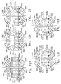
- FIG. 111 is a cross-sectional view of an end effector of a surgical stapler comprising a compressible staple cartridge positioned within a staple cartridge channel and a piece of buttress material attached to an anvil;
- FIG. 112 is a cross-sectional view of the end effector of FIG. 111 illustrating the anvil in a closed position
- FIG. 113 is a cross-sectional view of an alternative embodiment of an end effector of a surgical stapler comprising a staple cartridge comprising a water impermeable layer;
- FIG. 114 is a cross-sectional view of another alternative embodiment of an end effector of a surgical stapler
- FIG. 115 is a cross-sectional view of an alternative embodiment of an end effector of a surgical stapler comprising a stepped anvil and a staple cartridge comprising a stepped cartridge body;
- FIG. 116 is a cross-sectional view of another alternative embodiment of an end effector of a surgical stapler
- FIG. 117 is a cross-sectional view of an alternative embodiment of an end effector of a surgical stapler comprising inclined tissue-contacting surfaces;
- FIG. 118 is a cross-sectional view of another alternative embodiment of an end effector of a surgical stapler comprising inclined tissue-contacting surfaces;
- FIG. 119 is a cross-sectional view of an alternative embodiment of an end effector of a surgical stapler comprising a support insert configured to support a staple cartridge;
- FIG. 120 is a cross-sectional view of an alternative embodiment of an end effector of a surgical stapler comprising a staple cartridge comprising a plurality of compressible layers;
- FIG. 121 is a cross-sectional view of an alternative embodiment of an end effector of a surgical stapler comprising a staple cartridge comprising a stepped compressible cartridge body;
- FIG. 122 is a cross-sectional view of another alternative embodiment of an end effector of a surgical stapler comprising a staple cartridge comprising a stepped compressible cartridge body;
- FIG. 123 is a cross-sectional view of an alternative embodiment of an end effector of a surgical stapler comprising a staple cartridge comprising a curved tissue-contacting surface;
- FIG. 124 is a cross-sectional view of an alternative embodiment of an end effector of a surgical stapler comprising a staple cartridge having an inclined tissue-contacting surface;
- FIG. 125 is a cross-sectional view of a compressible staple cartridge comprising staples and at least one medicament stored therein;
- FIG. 126 is a diagram illustrating the compressible staple cartridge of FIG. 125 after it has been compressed and the staples contained therein have been deformed;
- FIG. 127 is a partial cut-away view of a staple cartridge in accordance with at least one embodiment
- FIG. 128 is a cross-sectional view of the staple cartridge of FIG. 127 ;
- FIG. 129 is a perspective view of an implanted staple cartridge in accordance with at least one alternative embodiment
- FIG. 130 is a cross-sectional view of the implanted staple cartridge of FIG. 129 ;
- FIG. 131 is a perspective view of an alternative embodiment of a staple cartridge comprising deformable members extending from an outer layer of the staple cartridge;
- FIG. 132 is a perspective view of an alternative embodiment of a staple cartridge comprising an outer layer of the staple cartridge being assembled to an inner layer;
- FIG. 133 is a cross-sectional view of an alternative embodiment of a staple cartridge comprising a plurality of staples, a compressible layer, and a pledget layer;
- FIG. 134 is a perspective view of the pledget layer of FIG. 133 ;
- FIG. 135 is a perspective view of a pledget singulated from the pledget layer of FIG. 133 and a staple aligned with a groove in the pledget;
- FIG. 136 is a perspective view of two connected pledgets from the pledget layer of FIG. 133 ;
- FIG. 137 is a perspective view of a pledget support frame of the pledget layer of FIG. 133 being removed from the singulated pledgets;
- FIG. 138 is an exploded perspective view of an alternative embodiment of a compressible staple cartridge comprising staples therein and a system for driving the staples against an anvil;
- FIG. 138A is a partial cut-away view of an alternative embodiment of the staple cartridge of FIG. 138 ;
- FIG. 139 is a cross-sectional view of the staple cartridge of FIG. 138 ;
- FIG. 140 is an elevational view of a sled configured to traverse the staple cartridge of FIG. 138 and move the staples to toward the anvil;
- FIG. 141 is a diagram of a staple driver which can be lifted toward the anvil by the sled of FIG. 140 ;
- FIG. 142 is a break-away view of a staple cartridge in accordance with at least one alternative embodiment comprising staples positioned within staple drivers;
- FIG. 143 is a cross-sectional view of the staple cartridge of FIG. 142 positioned within a staple cartridge channel;
- FIG. 144 is a cross-sectional view of the staple cartridge of FIG. 142 illustrating an anvil moved into a closed position and staples contained within the staple cartridge deformed by the anvil;
- FIG. 145 is a cross-sectional view of the staple cartridge of FIG. 142 illustrating the staples moved upwardly toward the anvil;
- FIG. 146 is a perspective view of an alternative embodiment of a staple cartridge comprising straps connecting the flexible sides of the staple cartridge;
- FIG. 147 is a perspective view of a sled and cutting member assembly
- FIG. 148 is a diagram of the sled and cutting member assembly of FIG. 147 being used to lift the staples of the staple cartridge of FIG. 142 ;
- FIG. 149 is a diagram illustrating a sled configured to engage and lift staples toward an anvil and a lock-out system configured to selectively permit the sled to move distally;
- FIGS. 150A-150C illustrate the progression of a staple being inserted into a staple crown
- FIG. 151 is a cross-sectional view of a staple cartridge comprising a support pan or retainer
- FIG. 152 is a partial cross-sectional view of a compressible staple cartridge in accordance with at least one alternative embodiment
- FIG. 153 is a diagram illustrating the staple cartridge of FIG. 152 in an implanted condition
- FIG. 154 is a partial cut-away view of a compressible staple cartridge in accordance with at least one alternative embodiment
- FIG. 155 is a partial cross-sectional view of the staple cartridge of FIG. 154 ;
- FIG. 156 is a diagram illustrating the staple cartridge of FIG. 154 in an implanted condition
- FIG. 157 is a partial cross-sectional view of a crushable staple cartridge in accordance with at least one alternative embodiment
- FIG. 158 is a partial cut-away view of a collapsible staple cartridge in accordance with at least one embodiment comprising a plurality of collapsible elements
- FIG. 159 is a perspective view of a collapsible element of FIG. 158 in an uncollapsed state
- FIG. 160 is a perspective view of the collapsible element of FIG. 159 in a collapsed state
- FIG. 161A is a partial cross-sectional view of an end effector of a surgical stapling instrument comprising a jaw, a staple cartridge channel positioned opposite the jaw, and a staple cartridge positioned within the staple cartridge channel, wherein the jaw comprises a retention matrix attached thereto;
- FIG. 161B is a partial cross-sectional view of the end effector of FIG. 161A illustrating the jaw being moved toward the staple cartridge channel, the staple cartridge being compressed by the anvil and the retention matrix, and a staple at least partially extending through tissue positioned intermediate the retention matrix and the staple cartridge;
- FIG. 161C is a partial cross-sectional view of the end effector of FIG. 161A illustrating the jaw in a final position and the retention matrix engaged with the staple of FIG. 161B ;
- FIG. 161D is a partial cross-sectional view of the end effector of FIG. 161A illustrating the jaw and the staple cartridge channel being moved away from the implanted staple cartridge and retention matrix;
- FIG. 162 is a perspective view of a retention aperture of a retention matrix in accordance with at least one alternative embodiment comprising a plurality of retention members configured to engage a fastener leg extending therethrough;
- FIG. 163 is a perspective view of a retention aperture of a retention matrix in accordance with at least one alternative embodiment comprising six retention members;
- FIG. 164 is a perspective view of a retention aperture of a retention matrix in accordance with at least one alternative embodiment comprising eight retention members;
- FIG. 165 is a perspective view of a retention aperture of a retention matrix in accordance with at least one alternative embodiment comprising a plurality of retention members configured to engage a fastener leg extending therethrough;
- FIG. 166 is a perspective view of a retention aperture of a retention matrix in accordance with at least one alternative embodiment comprising six retention members;
- FIG. 167 is a perspective view of a retention aperture of a retention matrix in accordance with at least one alternative embodiment comprising eight retention members;
- FIG. 168 is a perspective view of a retention aperture of a retention matrix in accordance with at least one alternative embodiment comprising a plurality of retention members that have been stamped from a sheet of metal;
- FIG. 169 is a perspective view of a retention aperture of a retention matrix in accordance with at least one alternative embodiment comprising a plurality of apertures extending around the perimeter of the retention aperture;
- FIG. 170 is a top view of a retention aperture of a retention matrix in accordance with at least one alternative embodiment
- FIG. 171 is a top view of a retention aperture of a retention matrix in accordance with at least one alternative embodiment
- FIG. 172 is a top view of a retention aperture of a retention matrix in accordance with at least one alternative embodiment
- FIG. 173 is a top view of a retention aperture of a retention matrix in accordance with at least one alternative embodiment
- FIG. 174 is a top view of a retention aperture of a retention matrix in accordance with at least one alternative embodiment
- FIG. 175 is a top view of a retention aperture of a retention matrix comprising a retention tab extending into the retention aperture in accordance with at least one embodiment
- FIG. 176 is a top view of a retention aperture of a retention matrix comprising a retention tab extending into the retention aperture in accordance with at least one alternative embodiment
- FIG. 177 is a perspective view of a fastening system comprising a plurality of staples, a retention matrix engaged with the staples, and an alignment matrix configured to align the staples;
- FIG. 178 is a perspective view of the retention matrix of FIG. 177 ;
- FIG. 179 is a perspective view of the alignment matrix of FIG. 177 ;
- FIG. 180 is a partial top view of the retention matrix of FIG. 177 engaged with the staples of FIG. 177 ;
- FIG. 181 is a partial bottom view of the retention matrix of FIG. 177 engaged with the staples of FIG. 177 ;
- FIG. 182 is a partial elevational view of the fastening system of FIG. 177 ;
- FIG. 183 is a partial perspective view of the fastening system of FIG. 177 ;
- FIG. 184 is a partial cross-sectional view of the retention matrix of FIG. 177 engaged with the staples of FIG. 177 ;
- FIG. 185 is a partial cross-sectional view of the fastening system of FIG. 177 ;
- FIG. 186 is a perspective view of the fastening system of FIG. 177 further comprising protective caps assembled to the legs of the staples;
- FIG. 187 is a bottom perspective view of the fastening system arrangement of FIG. 186 ;
- FIG. 188 is a partial perspective view of the fastening system arrangement of FIG. 186 ;
- FIG. 189 is a partial cross-sectional view of the fastening system arrangement of FIG. 186 ;
- FIG. 190 is an elevational view of an end effector in accordance with at least one embodiment comprising a jaw in an open position, a retention matrix and a plurality of protective caps positioned in the jaw, and a staple cartridge positioned in a staple cartridge channel;
- FIG. 191 is an elevational view of the end effector of FIG. 190 in a closed position
- FIG. 192 is an elevational view of the end effector of FIG. 190 in a fired position
- FIG. 193 is an elevational view of the retention matrix and protective caps of FIG. 190 assembled to the staple cartridge of FIG. 190 ;
- FIG. 194 is a detail view of the arrangement of FIG. 193 ;
- FIG. 195 is an elevational view of the end effector of FIG. 190 illustrating the jaw in an open position with thinner tissue positioned between the retention matrix and the staple cartridge;
- FIG. 196 is an elevational view of the end effector of FIG. 190 illustrating the jaw in a closed position against the thinner tissue of FIG. 195 ;
- FIG. 197 is an elevational view of the end effector of FIG. 190 illustrating the jaw in a fired position to capture the thinner tissue of FIG. 195 between the retention matrix and the staple cartridge;
- FIG. 198 is an elevational view of the retention matrix and the protective caps of FIG. 190 assembled to the staple cartridge of FIG. 190 with the thin tissue of FIG. 195 positioned therebetween;
- FIG. 199 is a detail view of the arrangement of FIG. 198 ;
- FIG. 200 is a cross-sectional view of a protective cap positioned on the tip of a staple leg in accordance with at least one alternative embodiment
- FIG. 201 is a perspective view of a plurality of protective caps embedded within a sheet of material
- FIG. 202 is a perspective view of a jaw comprising a plurality of recesses configured to receive a plurality of protective caps therein;
- FIG. 203 is a detail view of a portion of a jaw comprising a sheet covering the protective caps positioned within the jaw of FIG. 202 ;
- FIG. 204 is a cross-sectional view of a protective cap positioned on a tip of a staple leg in accordance with at least one alternative embodiment wherein the protective cap comprises an interior forming surface;
- FIG. 205 is another cross-sectional view of the protective cap of FIG. 204 illustrating the staple leg being deformed against the forming surface;
- FIG. 206 is a top view of an alternative embodiment of a retention matrix comprising a plurality of connected matrix elements
- FIG. 207 is a top view of an alternative embodiment of a retention matrix comprising a plurality of connected matrix elements
- FIG. 208 is a top view of an alternative embodiment of a retention matrix comprising a plurality of connected matrix elements
- FIG. 209 is a top view of an alternative embodiment of an array of retention matrices comprising a plurality of connected matrix elements
- FIG. 210 is a top view of an alternative embodiment of a retention matrix comprising a plurality of connected matrix elements
- FIG. 211 is a partial exploded view of a jaw comprising a retention matrix including a compressible cover
- FIG. 212 is a detail view of the retention matrix of FIG. 211 ;
- FIG. 213 is a partial cross-sectional view of a fastening system comprising a retention matrix including a compressible layer and a plurality of cells encapsulating one or more medicaments;
- FIG. 214 is a diagram illustrating staple legs which have pierced the cells of FIG. 213 as they are being engaged with the retention matrix;
- FIG. 215 is a partial cross-sectional view of a fastening system comprising a retention matrix including a compressible layer;
- FIG. 216 is an elevational view of a fastener cartridge insertion assembly comprising a holder, a first fastener cartridge, and a second fastener cartridge;
- FIG. 217 is an elevational view of an end effector of a surgical stapler comprising a first jaw and a second jaw, the second jaw being illustrated in an open configuration;
- FIG. 218 is an elevational view of the end effector of FIG. 217 illustrating the second jaw in a closed configuration and the fastener cartridge insertion assembly of FIG. 216 being used to load the first jaw with the first cartridge and the second jaw with the second cartridge;
- FIG. 219 is an elevational view of the loaded end effector of FIG. 218 illustrating the cartridge insertion assembly removed from the end effector, the second jaw in an open configuration once again, and tissue positioned intermediate the first jaw and the second jaw;
- FIG. 220 is an elevational view of the loaded end effector of FIG. 219 in a fired configuration
- FIG. 221 is an elevational view of the first cartridge and the second cartridge in an implanted condition
- FIG. 222 is an elevational view of the end effector of FIG. 217 illustrating a portion of the first cartridge still engaged with the first jaw in accordance with at least one embodiment
- FIG. 223 is an elevational view of an alternative embodiment of a fastener cartridge insertion assembly comprising a holder, a first fastener cartridge, and a second fastener cartridge;
- FIG. 224 is an elevational view of the fastener cartridge insertion assembly of FIG. 223 being used to load a first jaw of an end effector with the first cartridge and a second jaw with the second cartridge;
- FIG. 225 is a cross-sectional view of the loaded end effector of FIG. 224 ;
- FIG. 226 is a perspective view of a surgical stapler comprising a bottom jaw and a top jaw in accordance with at least one embodiment illustrated with portions of the surgical stapler removed;
- FIG. 227 is a perspective view of the surgical stapler of FIG. 226 with the top jaw removed;
- FIG. 228 is a perspective view of a slidable anvil system of the top jaw of the surgical stapler of FIG. 226 comprising a first slidable anvil and a second slidable anvil;
- FIG. 229 is an end view of the slidable anvil system of FIG. 228 ;
- FIG. 230 is a top view of the slidable anvil system of FIG. 228 ;
- FIG. 231 is a diagram illustrating the slidable anvil system of FIG. 228 in an unfired condition
- FIG. 232 is a diagram illustrating the first slidable anvil of the slidable anvil system of FIG. 228 in an unfired position and staples positioned within the bottom jaw in an undeployed position;
- FIG. 233 is a diagram illustrating the staples in the bottom jaw in a deployed configuration and the first slidable anvil of FIG. 232 being pulled proximally to deform a first group of staple legs of the staples;
- FIG. 234 is a diagram illustrating the first group of staples of FIG. 233 deformed to a fully deformed state
- FIG. 235 is a diagram illustrating the second slidable anvil of the slidable anvil system of FIG. 228 being pushed distally to deform a second group of staple legs;
- FIG. 236 is a partial perspective view of an anvil comprising a plurality of forming pockets in at least one embodiment
- FIG. 237 is a cross-sectional end view of the anvil of FIG. 236 ;
- FIG. 238 is a diagram illustrating a first step in manufacturing the forming pockets of FIG. 236 ;
- FIG. 239 is a diagram illustrating a second step in manufacturing the forming pockets of FIG. 236 ;
- FIG. 240 is a top view of the forming pocket arrangement of the anvil of FIG. 236 ;
- FIG. 241 is a diagram illustrating a first step of a manufacturing process for producing an anvil
- FIG. 242 is a diagram illustrating a second step in the manufacturing process of FIG. 241 ;
- FIG. 243 is a diagram illustrating a third step in the manufacturing process of FIG. 241 .
- proximal and distal are used herein with reference to a clinician manipulating the handle portion of the surgical instrument.
- proximal referring to the portion closest to the clinician and the term “distal” referring to the portion located away from the clinician.
- distal referring to the portion located away from the clinician.
- spatial terms such as “vertical”, “horizontal”, “up”, and “down” may be used herein with respect to the drawings.
- surgical instruments are used in many orientations and positions, and these terms are not intended to be limiting and/or absolute.
- FIG. 1 depicts a surgical instrument 10 that is capable of practicing several unique benefits of the present invention.
- the surgical stapling instrument 10 is designed to manipulate and/or actuate various forms and sizes of end effectors 12 that are operably attached thereto.
- the end effector 12 includes an elongated channel 14 that forms a lower jaw 13 of the end effector 12 .
- the elongated channel 14 is configured to support an “implantable” staple cartridge 30 and also movably support an anvil 20 that functions as an upper jaw 15 of the end effector 12 .
- the elongated channel 14 may be fabricated from, for example, 300 & 400 Series, 17-4 & 17-7 stainless steel, titanium, etc. and be formed with spaced side walls 16 .
- the anvil 20 may be fabricated from, for example, 300 & 400 Series, 17-4 & 17-7 stainless steel, titanium, etc. and have a staple forming undersurface, generally labeled as 22 that has a plurality of staple forming pockets 23 formed therein. See FIGS. 1B-1E .
- the anvil 20 has a bifurcated ramp assembly 24 that protrudes proximally therefrom.
- An anvil pin 26 protrudes from each lateral side of the ramp assembly 24 to be received within a corresponding slot or opening 18 in the side walls 16 of the elongated channel 14 to facilitate its movable or pivotable attachment thereto.
- implantable staple cartridges may be employed with the various embodiments of the surgical instruments disclosed herein. Specific staple cartridge configurations and constructions will be discussed in further detail below. However, in the embodiment depicted in FIGS. 1 A and 9 - 14 , an implantable staple cartridge 30 is shown.
- the staple cartridge 30 has a body portion 31 that consists of a compressible hemostat material such as, for example, oxidized regenerated cellulose (“ORC”) or a bio-absorbable foam in which lines of unformed metal staples 32 are supported.
- a compressible hemostat material such as, for example, oxidized regenerated cellulose (“ORC”) or a bio-absorbable foam in which lines of unformed metal staples 32 are supported.
- the entire cartridge may be coated or wrapped in a biodegradable film 38 such as a polydioxanone film sold under the trademark PDS® or with a Polyglycerol sebacate (PGS) film or other biodegradable films formed from PGA (Polyglycolic acid, marketed under the trade mark Vicryl), PCL (Polycaprolactone), PLA or PLLA (Polylactic acid), PHA (polyhydroxyalkanoate), PGCL (poliglecaprone 25, sold under the trademark Monocryl) or a composite of PGA, PCL, PLA, PDS that would be impermeable until ruptured.
- PGA Polyglycolic acid, marketed under the trade mark Vicryl
- PCL Polycaprolactone
- PLA or PLLA Polylactic acid
- PHA polyhydroxyalkanoate
- PGCL poliglecaprone 25, sold under the trademark Monocryl
- the body 31 of staple cartridge 30 is sized to be removably supported within the elongated channel 14 as shown such that each staple 32 therein is aligned with corresponding staple forming pockets 23 in the anvil when the anvil 20 is driven into forming contact with the staple cartridge 30 .
- the end effector 12 is manipulated to capture or clamp the target tissue between an upper face 36 of the staple cartridge 30 and the staple forming surface 22 of the anvil 20 .
- the staples 32 are formed by moving the anvil 20 in a path that is substantially parallel to the elongated channel 14 to bring the staple forming surface 22 and, more particularly, the staple forming pockets 23 therein into substantially simultaneous contact with the upper face 36 of the staple cartridge 30 .
- the legs 34 of the staples 32 contact a corresponding staple forming pocket 23 in anvil 20 which serves to bend the staple legs 34 over to form the staples 32 into a “B shape”. Further movement of the anvil 20 toward the elongated channel 14 will further compress and form the staples 32 to a desired final formed height “FH”.
- FIGS. 1B-1E The above-described staple forming process is generally depicted in FIGS. 1B-1E .
- FIG. 1B illustrates the end effector 12 with target tissue “T” between the anvil 20 and the upper face 36 of the implantable staple cartridge 30 .
- FIG. 1C illustrates the initial clamping position of the anvil 20 wherein the anvil has 20 been closed onto the target tissue “T” to clamp the target tissue “T” between the anvil 20 and the upper face 36 of the staple cartridge 30 .
- FIG. 1D illustrates the initial staple formation wherein the anvil 20 has started to compress the staple cartridge 30 such that the legs 34 of the staples 32 are starting to be formed by the staple forming pockets 23 in the anvil 20 .
- FIG. 1B illustrates the end effector 12 with target tissue “T” between the anvil 20 and the upper face 36 of the implantable staple cartridge 30 .
- FIG. 1C illustrates the initial clamping position of the anvil 20 wherein the anvil has 20 been closed onto the target tissue “T
- FIG. 1E illustrates the staple 32 in its final formed condition through the target tissue “T” with the anvil 20 removed for clarity purposes.
- the surgeon will move the anvil 20 to the open position to enable the cartridge body 31 and the staples 32 to remain affixed to the target tissue while the end effector 12 is being withdrawn from the patient.
- the end effector 12 forms all of the staples simultaneously as the two jaws 13 , 15 are clamped together.
- the remaining “crushed” body materials 31 act as both a hemostat (the ORC) and a staple line reinforcement (PGA, PDS or any of the other film compositions mentioned above 38 ).
- implantable means that, in addition to the staples, the cartridge body materials that support the staples will also remain in the patient and eventually be absorbed by the patient's body.
- implantable staple cartridges are distinguishable from prior cartridge arrangements that remain with the end effector and are removed therewith.
- Those “removable” staple cartridges typically include staple driver components and therefore may be much larger than the end effectors of the present invention that are designed to be employed in connection with certain unique and novel implantable staple cartridge embodiments of the present invention.
- the end effector 12 is configured to be coupled to an elongated shaft assembly 40 that protrudes from a handle assembly 100 .
- the end effector 12 (when closed) and the elongated shaft assembly 40 may have similar cross-sectional shapes and be sized to operably pass through a trocar tube or working channel in another form of access instrument.
- the term “operably pass” means that the end effector and at least a portion of the elongated shaft assembly may be inserted through or passed through the channel or tube opening and can be manipulated therein as needed to complete the surgical stapling procedure.
- the jaws 13 and 15 of the end effector 12 may provide the end effector with a roughly circular cross-sectional shape that facilitates its passage through a circular passage/opening.
- the end effectors of various embodiments of the present invention, as well as the elongated shaft assembly embodiments could conceivably be provided with other cross-sectional shapes that could otherwise pass through access passages and openings that have non-circular cross-sectional shapes.
- an overall size of a cross-section of a closed end effector will be related to the size of the passage or opening through which it is intended to pass.
- one end effector for example, may be referred to as a “5 mm” end effector which means it can operably pass through an opening that is at least approximately 5 mm in diameter.
- the elongated shaft assembly 40 may have an outer diameter that is substantially the same as the outer diameter of the end effector 12 when in a closed position.
- a 5 mm end effector may be coupled to an elongated shaft assembly 40 that has 5 mm cross-sectional diameter.
- a 10 mm end effector may be attached to an elongated shaft that has a 5 mm cross-sectional diameter.
- the elongated shaft assembly 40 may have a 10 mm (or larger) cross-sectional diameter, but may also be able to actuate a 5 mm or 10 mm end effector. Accordingly, the outer shaft 40 may have an outer diameter that is the same as or is different from the outer diameter of a closed end effector 12 attached thereto.
- the elongated shaft assembly 40 extends distally from the handle assembly 100 in a generally straight line to define a longitudinal axis A-A.
- the elongated shaft assembly 40 may be approximately 9-16 inches (229-406 mm) long.
- the elongated shaft assembly 40 may be provided in other lengths and, in other embodiments, may have joints therein or be otherwise configured to facilitate articulation of the end effector 12 relative to other portions of the shaft or handle assembly as will be discussed in further detail below.
- the elongated shaft assembly 40 includes a spine member 50 that extends from the handle assembly 100 to the end effector 12 .
- the proximal end of the elongated channel 14 of the end effector 12 has a pair of retention trunions 17 protruding therefrom that are sized to be received within corresponding trunion openings or cradles 52 that are provided in a distal end of the spine member 50 to enable the end effector 12 to be removably coupled the elongated shaft assembly 40 .
- the spine member 50 may be fabricated from, for example, 6061 or 7075 aluminum, stainless steel, titanium, etc.
- the handle assembly 100 comprises a pistol grip-type housing that may be fabricated in two or more pieces for assembly purposes.
- the handle assembly 100 as shown comprises a right hand case member 102 and a left hand case member 104 ( FIGS. 5 , 7 , and 8 ) that are molded or otherwise fabricated from a polymer or plastic material and are designed to mate together.
- Such case members 102 and 104 may be attached together by snap features, pegs and sockets molded or otherwise formed therein and/or by adhesive, screws, etc.
- the spine member 50 has a proximal end 54 that has a flange 56 formed thereon.
- the flange 56 is configured to be rotatably supported within a groove 106 formed by mating ribs 108 that protrude inwardly from each of the case members 102 , 104 .
- Such arrangement facilitates the attachment of the spine member 50 to the handle assembly 100 while enabling the spine member 50 to be rotated relative to the handle assembly 100 about the longitudinal axis A-A in a 360° path.
- the spine member 50 passes through and is supported by a mounting bushing 60 that is rotatably affixed to the handle assembly 100 .
- the mounting bushing 60 has a proximal flange 62 and a distal flange 64 that define a rotational groove 65 that is configured to rotatably receive a nose portion 101 of the handle assembly 100 therebetween.
- the spine member 50 is non-rotatably pinned to the mounting bushing 60 by a spine pin 66 .
- a rotation knob 70 is attached to the mounting bushing 60 .
- the rotation knob 70 has a hollow mounting flange portion 72 that is sized to receive a portion of the mounting bushing 60 therein.
- the rotation knob 70 may be fabricated from, for example, glass or carbon filled Nylon, polycarbonate, Ultem®, etc. and is affixed to the mounting bushing 60 by the spine pin 66 as well.
- an inwardly protruding retention flange 74 is formed on the mounting flange portion 72 and is configured to extend into a radial groove 68 formed in the mounting bushing 60 .
- the surgeon may rotate the spine member 50 (and the end effector 12 attached thereto) about longitudinal axis A-A in a 360° path by grasping the rotation knob 70 and rotating it relative to the handle assembly 100 .
- the anvil 20 is retained in an open position by an anvil spring 21 or other biasing arrangement as depicted in FIGS. 1 , 9 A, 10 A, and 11 A.
- the anvil 20 is selectively movable from the open position to various closed or clamping and firing positions by a firing system, generally designated as 109 .
- the firing system 109 includes a “firing member” 110 which, in various embodiments, comprises a hollow firing tube 110 .
- the hollow firing tube 110 is axially movable on the spine member 50 and thus forms the outer portion of the elongated shaft assembly 40 .
- the firing tube 110 may be fabricated from a polymer or other suitable material and have a proximal end 112 that is attached to a firing yoke 114 of the firing system 109 . See FIG. 4 .
- the firing yoke 114 may be over-molded to the proximal end 112 of the firing tube 110 .
- other fastener arrangements may be employed.
- the firing yoke 114 may be rotatably supported within a support collar 120 that is configured to move axially within the handle assembly 100 .
- the support collar 120 has a pair of laterally extending fins 122 that are sized to be slidably received within fin slots 103 and 105 formed in the right and left hand case members 102 , 104 , respectively. See FIG. 7 .
- the support collar 120 may slide axially within the handle housing 100 while enabling the firing yoke 114 and firing tube 110 to rotate relative thereto about the longitudinal axis A-A.
- a longitudinal slot 111 is provided through the firing tube 110 to enable the spine pin 66 to extend therethrough into the spine member 50 while facilitating the axial travel of the firing tube 110 on the spine member 50 .
- the firing system 109 further comprises a firing trigger 130 which serves to control the axial travel of the firing tube 110 on the spine member 50 . See FIG. 1 .
- a firing trigger 130 which serves to control the axial travel of the firing tube 110 on the spine member 50 . See FIG. 1 .
- Such axial movement in the distal direction of the firing tube 110 into firing interaction with the anvil 20 is referred to herein as “firing motion”.
- the firing trigger 130 is movably or pivotally coupled to the handle assembly 100 by a pivot pin 132 .
- a torsion spring 135 is employed to bias the firing trigger 130 away from the pistol grip portion 107 of the handle assembly 100 to an un-actuated “open” or starting position.
- the firing trigger 130 has an upper portion 134 that is movably attached to (pinned) firing links 136 that are movably attached to (pinned) the support collar 120 .
- movement of the firing trigger 130 from the starting position ( FIGS. 1 and 9 ) toward an ending position adjacent the pistol grip portion 107 of the handle assembly 100 ( FIG. 14 ) will cause the firing yoke 114 and the firing tube 110 to move in the distal direction “DD”.
- Movement of the firing trigger 130 away from the pistol grip portion 107 of the handle assembly 100 (under the bias of the torsion spring 135 ) will cause the firing yoke 114 and firing tube 110 to move in the proximal direction “PD” on the spine member 50 .
- the surgical instrument 10 when used in connection with a first firing adapter 140 , may be used with a 5 mm end effector 12 that is approximately 20 mm long (or in other lengths) which supports an implantable staple cartridge 30 .
- Such end effector size may be particularly well-suited, for example, to complete relatively fine dissection and vascular transactions.
- the surgical instrument 10 may also be employed, for example, in connection with other sizes of end effectors and staple cartridges by replacing the first firing adapter 140 with a second firing adapter 150 .
- the elongated shaft assembly 40 may be attached to only one form or size of end effector.
- the pressure surfaces 146 or 158 (normally provided on the firing adapters 140 , 150 , respectively) would be integrally formed in the distal end of the firing tube 110 —depending upon the particular size of end effector with which it is to be used.
- the first firing adapter 140 is substantially hollow and has a first spring portion 142 that is configured to extend into an open distal end 116 of the firing tube 110 .
- a first retainer button 144 is formed on the first spring portion 142 and is sized to be received within a retaining hole 117 provided in the distal end portion of the firing tube 110 . See FIGS. 1 and 2 .
- the user simply depresses the retainer button 144 out of the retaining hole 117 and withdraws the first firing adapter 140 out of the firing tube 110 .
- the first firing adapter 140 has an interior pressure surface 146 that is configured to interface with the bifurcated ramp assembly 24 of the anvil 20 .
- the bifurcated ramp assembly 24 on the anvil 20 comprises a pair of tines 45 that are separated by a blade-receiving groove (not shown).
- Each tine 45 has a proximal surface 27 that is substantially parallel to the bottom of the elongated channel 14 when the anvil 20 is in a closed position.
- the proximal surface 27 then transitions into a clamping ramp 28 that is distal to the proximal surface 27 . See FIG. 3 .
- the clamping ramp 28 is oriented at a clamping angle “A” with respect to the proximal surface 27 . In various embodiments, for example, clamping angle “A” may be approximately 15 to 30 degrees.
- the anvil 20 will be moved toward the elongated channel 14 and more specifically toward the staple cartridge 30 therein.
- the first pressure surface 146 contacts a staple forming ramp 29 on each of the anvil tines 45 to further drive the anvil 20 into the staple cartridge 30 to form the staples 32 therein.
- the staple forming ramp 29 is oriented at a forming angle “B” relative to the clamping ramp 27 . In various embodiments, for example, forming angle “B” may be approximately 5 to 20 degrees.
- the ramp assembly 24 of the anvil 20 may further have a sloped under surface 25 thereon (e.g., angle “C” is approximately 5 to 40 degrees) such that when the anvil 20 is in an open position, the sloped undersurface 25 surface enables the anvil 20 to pivot to a 15° open limit (angle “ ⁇ ” in FIG. 11A ).
- the coupling process is commenced by inserting the retention trunions 17 on the elongated channel 14 into the trunion cradles 52 in the spine member 50 . Thereafter, the surgeon advances the firing trigger 130 toward the pistol grip 107 of the housing assembly 100 to distally advance the firing tube 110 and the first firing adapter 140 over a proximal end portion 47 of the elongated channel 14 to thereby retain the trunions 17 in their respective cradles 52 . See FIGS. 10 and 10A . Such position of the first firing adapter 140 over the trunions 17 is referred to herein as the “coupled position”.
- Various embodiments of the present invention may also have an end effector locking assembly 160 for locking the firing trigger 130 in position after an end effector 12 has been attached to the spine member 50 .
- one embodiment of the end effector locking assembly 160 includes a retention pin 162 that is movably supported in the upper portion 134 of the firing trigger 130 .
- the retention pin 162 is spring-biased toward the left hand case member 104 by a retention spring 166 .
- the firing trigger 130 is in an un-actuated (starting) position, the retention pin 162 is biased into abutting contact with a start detent 163 that protrudes inwardly from the left hand case member 104 . See FIGS. 7 and 8 .
- the firing tube 110 must initially be advanced distally to the coupled position wherein the first firing adapter 140 retains the retention trunions 17 of the end effector 12 in the trunion cradles 52 in the spine member 50 .
- the surgeon advances the firing adapter 140 distally to the coupled position by pulling the firing trigger 130 from the starting position toward the pistol grip 107 .
- the retention pin 162 slides in abutting contact with the start detent 163 until the firing tube 110 has advanced the first firing adapter 140 to the coupled position at which point the retention pin 162 is biased into a locking cavity 164 formed in the left hand case member 104 . See FIG. 8 .
- the pin 162 when the retention pin 162 enters into the locking cavity 164 , the pin 162 may make an audible “click” or other sound, as well as provide a tactile indication to the surgeon that the end effector 12 has been “locked” onto the spine member 50 .
- the surgeon cannot inadvertently continue to actuate the firing trigger 130 to start to form staples 32 in the end effector 12 without intentionally biasing the retention pin 162 out of the locking cavity 164 .
- the surgeon releases the firing trigger 130 when in the coupled position, it is retained in that position by the retention pin 162 to prevent the firing trigger 130 from returning to the starting position and thereby releasing the end effector 12 from the spine member 50 .
- a firing trigger release button 167 is mounted within the left hand case member 104 of the handle assembly 100 to enable the surgeon to intentionally release the retention pin 162 to enable the firing trigger 130 to be further actuated or returned to the starting position. See FIGS. 5 , 7 , and 8 .
- the firing trigger release button 167 is movably mounted within the locking cavity 164 and is spring-biased to an un-activated position ( FIG. 8 ). When the firing trigger release button 167 is pressed inwardly, it contacts the retention pin 162 and moves it out of the locking cavity 163 to enable the firing trigger 130 to be further activated.
- the surgical instrument 10 may be used as a grasping device to manipulate/position tissue. Further movement of the firing trigger 130 toward the pistol grip portion 107 after the trigger 130 has been unlocked (by depressing the retention release button 167 ) will cause the firing adapter 140 to contact the clamping ramp 28 on the anvil 20 . As the pressure surface portion 146 of the first firing adapter rides up the clamping ramp 28 , the anvil will move towards the staple cartridge 30 in the elongated channel 14 . Thus, the surgeon may manipulate the anvil 20 toward and away from the staple cartridge 30 to grasp and release tissue therebetween without forming the staples.
- Various embodiments of the present invention may further include a firing system lock button 137 that is pivotally attached to the handle assembly 100 . See FIGS. 1 and 4 .
- the firing system lock button 137 has a latch 138 formed on a distal end thereof that is oriented to engage the firing yoke 114 when the firing release button is in a first latching position.
- a latch spring 139 serves to bias the firing system lock button 137 to the first latching position ( FIGS. 11 and 12 ).
- the latch 138 serves to engage the firing yoke 114 at a point where the position of the firing yoke 114 on the spine member 50 corresponds to a point wherein the pressure surface 146 of the first firing adapter 140 is about to distally advance up the clamping ramp 28 on the anvil 20 . It will be understood that, as the first firing adapter 140 advances axially up the clamping ramp 28 , the anvil 20 will move in a path such that its staple forming surface portion 22 is substantially parallel to the upper face 36 of the staple cartridge 30 .
- the staple forming process is commenced by first depressing the firing system lock button 137 to enable the firing yoke 114 to be further moved distally on the spine member 50 and ultimately compress the anvil 20 into the staple cartridge 30 . See FIG. 13 .
- the surgeon continues to actuate the firing trigger 130 towards the pistol grip 107 thereby driving the pressure surface 146 of the first staple collar 140 up the corresponding staple forming ramp 29 to force the anvil 20 into forming contact with the staples 32 in the staple cartridge 30 .
- the firing system lock button 137 prevents the inadvertent forming of the staples 32 until the surgeon is ready to start that process. In this embodiment, the surgeon must depress the firing system lock button 137 before the firing trigger 130 may be further actuated to begin the staple forming process.
- the surgical instrument 10 may be solely used as a tissue stapling device if so desired.
- various embodiments of the present invention may also include a tissue cutting system, generally designated as 170 .
- the tissue cutting system 170 comprises a knife member 172 that may be selectively advanced from an un-actuated position adjacent the proximal end of the end effector 12 (FIGS. 1 and 9 - 13 ) to an actuated position ( FIG. 14 ) by actuating a knife advancement trigger 200 .
- the knife member 172 is movably supported within the spine member 50 and is attached or otherwise protrudes from a knife rod 180 .
- the knife member 172 may be fabricated from, for example, 420 or 440 stainless steel with a hardness of greater than 38HRC (Rockwell Hardness C-scale) and have a tissue cutting edge 176 formed on the distal end 174 thereof and be configured to slidably extend through a slot 31 in the anvil 20 and a centrally disposed slot 33 in the staple cartridge 30 to cut through tissue that is clamped in the end effector 12 . See FIG. 14A .
- the knife rod 180 extends through the spine member 50 and has a proximal end portion 182 .
- the proximal end portion 182 drivingly interfaces with a knife transmission 190 that is operably attached to the knife advance trigger 200 .
- the knife advance trigger 200 is attached to pivot pin 132 such that it may be pivoted or otherwise actuated without actuating the firing trigger 130 .
- a first knife gear 192 is also attached to the pivot pin 132 such that actuation of the knife advance trigger 200 also pivots the first knife gear 192 .
- a firing return spring 202 is attached between the first knife gear 192 and the handle housing 100 to bias the knife advancement trigger 200 to a starting or un-actuated position. See FIGS. 1 and 4 .
- various embodiments of the knife transmission 190 also include a second knife gear 194 that is rotatably supported on a second gear spindle 193 and in meshing engagement with the first knife gear 192 .
- the second knife gear 194 is in meshing engagement with a third knife gear 196 that is supported on a third gear spindle 195 .
- Also supported on the third gear spindle 195 is a fourth knife gear 198 .
- the fourth knife gear 198 is adapted to drivingly engage a series of annular gear teeth or rings 184 on a proximal end of the knife rod 180 .
- such arrangement enables the fourth knife gear 198 to axially drive the knife rod 180 in the distal direction “DD” or proximal direction “PD” while enabling the firing rod 180 to rotate about longitudinal axis A-A with respect to the fourth knife gear 198 . Accordingly, the surgeon may axially advance the firing rod 180 and ultimately the knife member 172 distally by pulling the knife advancement trigger 200 towards the pistol grip 107 of the handle assembly 100 .
- Various embodiments of the present invention further include a knife lockout system 210 that prevents the advancement of the knife member 72 unless the firing trigger 130 has been pulled to the fully fired position ( FIGS. 13 and 14 ). Such feature will therefore prevent the activation of the knife advancement system 170 unless the staples have first been fired or formed into the tissue.
- various implementations of the knife lockout system 210 comprise a knife lockout bar 211 that is pivotally supported within the pistol grip portion 107 of the handle assembly 100 .
- the knife lockout bar 211 has an activation end 212 that is adapted to be engaged by the firing trigger 130 when the firing trigger 130 is in the fully fired position.
- the knife lockout bar 211 has a retaining hook 214 on its other end that is adapted to hookingly engage a latch rod 216 on the first cut gear 192 .
- a knife lock spring 218 is employed to bias the knife lockout bar 211 to a “locked” position wherein the retaining hook 214 is retained in engagement with the latch rod 216 to thereby prevent actuation of the knife advancement trigger 200 unless the firing trigger 130 is in the fully fired position. See FIG. 9 .
- FIGS. 9 , 9 A, 10 , 10 A, 11 , 11 A, 12 , 12 A, 13 , 13 A, 14 , and 14 A As can be appreciated from reference to FIGS. 1 , 9 and 9 A, when the knife bar 172 is in the depicted “starting” or un-actuated position, the tissue cutting edge 176 is proximal to the distal end of the first firing adapter 140 such that the sharp tissue cutting edge 176 is not exposed to the user.
- the cutting edge 176 of the knife bar 172 would be located proximal to the distal end of the firing tube to prevent the tissue cutting edge 176 from being exposed to the user in those embodiments as well.
- FIGS. 9 and 9A illustrate the end effector 12 after it has been attached to the spine member 50 by inserting the retention trunions 17 on the end effector 12 into the trunion cradles 52 in the spine member 50 .
- the firing trigger 130 is in an un-actuated or starting position and the end effector 12 has not yet been locked to the spine member 50 by the first firing adapter 140 .
- “P O ” represents the distance that the firing trigger 130 can travel before the first firing adapter 140 starts to travel up the clamping ramp portion 28 of the anvil 20 .
- the knife advancement trigger 200 is also in a locked un-actuated position.
- FIGS. 10 and 10A illustrate the position of the firing trigger 130 after it has been advanced to a position wherein the end effector 12 is been locked to the spine member 50 by the first firing adapter 40 .
- This position is referred to herein as the “coupled” position.
- the retention pin 162 When in the coupled position, the retention pin 162 has snapped into the locking cavity 164 ( FIG. 8 ) to thereby provide the surgeon with an audible and tactile indication that the end effector 12 is now locked to the spine member 50 .
- the firing trigger 130 cannot be actuated further until the surgeon intentionally depresses the firing trigger release button 167 ( FIGS. 5 , 7 , and 8 ) to bias the retention pin 62 out of the locking cavity 164 .
- FIGS. 11 and 11A illustrate a position of the firing trigger 130 after the release button (not shown) has been depressed and the surgeon has activated the firing trigger 130 to move the first firing adapter 140 to the beginning of the clamping ramps 28 on the anvil 20 .
- the anvil spring 21 has biased the anvil 20 to an open position.
- FIGS. 12 and 12A illustrate the position of the first firing adapter 140 after it has been advanced to the start of the staple forming ramp 29 of the anvil 20 . This position represents the maximum amount of clamping that can be attained before staple formation begins. This position is referred to herein as a “maximum clamped position”. As can be seen in FIG. 12 , the firing yoke 114 has contacted the latch 138 on the firing trigger release button 137 and therefore cannot be further advanced distally until the firing trigger release button 137 has been depressed.
- C max may be, for example, 0.085 to 0.144 inches (approximately 2.15 to 3.65 mm) for staple cartridges 30 with body portions 31 that have a substantially equivalent thickness.
- the cartridge thickness may be as much as approximately 0.01 to 0.03 inches (approximately 0.25 mm to 0.76 mm) larger than the staple size.
- FIGS. 13 and 13A illustrate the position of the firing yoke 114 in a fully fired position wherein the staples 32 in the staple cartridge 30 have been fully formed. When in that position, the distance between the staple forming portion 22 of the anvil 20 and the top retaining surface of the elongated channel 14 is represented as “C min .”.
- C min may be, for example, approximately 0.015 to 0.030 inches (approximately 0.38 mm to 0.76 mm) for staple cartridges that support staples that, when unformed, have legs that are approximately 0.075 to 0.134 inches (approximately 1.90 mm to 3.40 mm) long (distance “UF” in FIG. 1A ) and when fully formed have a fully formed height of, for example, approximately 0.025 inches to 0.04 inches (approximately 0.63 mm to 1.01 mm) which comprises distance “FF” in FIG. 1D .
- the total distance that the first firing adapter 140 has traveled from the starting position to this fully fired position is represented as “l 3 ” and the corresponding distance that the firing yoke 114 has traveled on the spine member 50 is represented as “l′ 3 ”.
- the firing trigger 130 is in the fully fired position and has contacted the activation end 212 of the knife lockout bar 211 to bias the retaining hook 214 out of engagement with the latch rod 216 on the first cut gear 192 .
- Transection especially of vessels may be one of the highest stress steps of any surgical procedure.
- it is even more stressful because if something fails, the entire procedure may need to be converted to an open procedure almost immediately in order to prevent catastrophic events from occurring.
- it may be desirable to employ a surgical stapling instrument that has the ability to optionally cut tissue after the staples have been deployed.
- Various embodiments of the present invention meet such needs.
- the surgeon may depress the firing trigger release button 167 to enable the firing trigger 130 to return to the starting position under the bias of the torsion spring 135 which enables the anvil 20 to be biased to an open position under the bias of spring 21 .
- the surgeon may withdraw the end effector 12 leaving the implantable staple cartridge 30 and staples 32 behind.
- the surgeon will return the anvil 20 to the closed position by activating the firing trigger 130 to enable the end effector 12 to be withdrawn out through the passage or working channel.
- FIG. 14 illustrates the amount of travel of the knife advancement trigger 200 in various embodiments for different lengths of end effectors/staple cartridges wherein the knife bar 72 has been advanced to the fully fired position within the end effector 12 . Thereafter, the surgeon may release the knife advancement trigger 200 to enable the firing return spring 202 to cause the firing transmission to return the knife bar 72 to the starting (un-actuated) position ( FIGS. 13 , 13 A).
- the surgeon may open the end effector jaws 13 , 15 to release the implantable cartridge 30 within the patient and then withdraw the end effector 12 from the patient.
- surgical instruments of the present invention facilitate the use of small implantable staple cartridges that may be inserted through relatively smaller working channels and passages, while providing the surgeon with the option to fire the staples without cutting tissue or if desired to also cut tissue after the staples have been fired.
- FIGS. 15-19 illustrate use of an end effector 12 ′ which operably supports a staple cartridge 30 ′ that has staples 32 ′ that are larger than the staples 32 in the staple cartridge 30 .
- the staples 32 in a staple cartridge 30 may be approximately 0.080-0.085 inches (approximately 2.03 to 2.15 mm staples, whereas the staples 32 ′ in the staple cartridge 30 ′ may be approximately 0.075 inches (approximately 1.90 mm).
- the staple cartridge 30 ′ is longer than the staple cartridge 30 .
- FIG. 15 is an exploded view of an end effector 12 ′, a second firing adapter 150 and the distal end 55 of the spine member 50 .
- the elongated channel 14 ′ has a pair of spaced side walls 16 ′ that each has a slot or opening 18 ′ therein that is sized to receive a corresponding anvil pin 26 ′.
- the anvil 20 ′ and the elongated channel 14 ′ may together form an end effector 12 ′ that has an overall diameter that would permit the end effector 12 ′ to pass through an opening that has a diameter of at least approximately 0.20 inches (approximately 5.0 mm).
- the anvil 20 ′ also has a staple forming portion 22 ′ that has a plurality of staple forming pockets formed therein and a bifurcated ramp assembly 24 ′ that protrudes proximally therefrom.
- the proximal end 15 ′ of the elongated channel 14 ′ has a pair of retention trunions 17 ′ protruding therefrom that are sized to be received within corresponding trunion cradles 52 that are provided in the spine member 50 .
- the second firing adapter 150 has a substantially hollow body portion 151 and a proximal collar portion 152 that has an inwardly extending retaining protrusion 154 therein.
- a slot 156 is provided between the body portion 151 and the proximal collar portion 152 to enable the collar portion 152 to be biased relative to the body portion 151 to facilitate the insertion of the retaining protrusion 154 into the retaining hole 117 in the firing tube 110 .
- the surgeon depresses the proximal collar portion 152 to move the retaining protrusion 154 out of the retaining hole 117 to thereby enable the second firing adapter 150 to be pulled distally off of the firing tube 110 .
- the anvil 20 ′ has a bifurcated ramp assembly 24 ′ that comprises a pair of tines 45 ′ that each has a proximal surface 27 ′ that transitions into a clamping ramp 28 ′ that is distal to the proximal surface 27 ′. See FIG. 15 .
- the clamping ramp 28 ′ is oriented at an angle “A′” with respect to the proximal surface 27 ′. In various embodiments, for example, angle “A”′ may be approximately 50 to 30 degrees.
- the anvil 20 ′ will be moved toward the elongated channel 14 ′ and more specifically toward the staple cartridge 30 ′ therein. See FIG. 17 .
- the second pressure surface 158 contacts staple forming ramps 29 ′ on the anvil tines 45 to further drive the anvil 20 ′ toward the staple cartridge 30 ′ to form the staples 32 ′ therein. See FIG. 18 .
- the staple forming ramp 29 ′ is oriented at an angle “B” relative to the clamping ramp 27 ′. In various embodiments, for example, angle “B” may be approximately 5 to 20 degrees.
- a spring (not shown) may be provided between the ramp assembly 24 ′ and the bottom of the elongated channel 14 ′ to bias the anvil 20 ′ to that open position.
- FIG. 16 shows the position of the second firing adapter 150 after the surgeon has distally advanced the second firing adapter 150 to the start of the clamping ramp portions 28 ′. Operation of the second firing adapter 150 is controlled by the firing trigger 130 in the manner described above with respect to the first firing adapter 140 .
- FIG. 17 illustrates the position of the second firing adapter 150 in a fully clamped position.
- FIG. 18 illustrates the position of the second firing adapter 150 in the fully fired position wherein the staples 32 ′ in the staple cartridge 30 ′ have been formed through the clamped tissue (not shown).
- the implantable staple cartridge 30 ′ is longer than the implantable staple cartridge 30 .
- the end effector 12 ′ also includes a distal knife member 124 that is movably supported in the elongated channel 14 ′.
- the distal knife member 124 has a tissue cutting edge 125 and a proximal portion 126 that is configured for engagement by the knife bar 72 .
- the surgeon activates the firing trigger 200 as described above to drive the knife bar 172 distally into contact with the distal knife member 124 to drive the distal knife member 124 through the tissue as illustrated in FIG. 19 .
- the distal knife member 124 may have at least one retainer portion thereon that is adapted to slide through a correspondingly shaped slot (not shown) in the elongated channel 14 ′. Such arrangement enables the end effector 12 ′ to be opened after the staples have been formed and the tissue has been cut. The distal knife member 124 remains in the anvil 20 ′ and is removed with the end effector 12 ′ when it is withdrawn from the patient.
- various embodiments of the surgical instrument 10 have separate stapling and tissue cutting mechanisms such that the surgeon may staple the tissue without cutting the tissue.
- the various embodiments of the stapling instrument of the present invention can be successfully employed with different sizes of end effectors that are adapted to fire different sizes and numbers of staples.
- the surgical instruments may be provided in the form of a kit that includes an instrument 10 and a first firing adapter 140 and a second firing adapter 150 that enables the instrument to be employed to fire different sizes of implantable staple cartridges.
- Various unique and novel embodiments of the present invention employ a compressible staple cartridge that supports staples in a substantially stationary position for forming contact by the anvil.
- the staples in the cartridges of various embodiments of the present invention are not driven into the anvil.
- the anvil is driven into the unformed staples.
- the degree of staple formation attained is dependent upon how far the anvil is driven into the staples.
- Such arrangement provides the surgeon with the ability to adjust the amount of forming or firing pressure applied to the staples and thereby alter the final formed height of the staples.
- the amount of firing motion that is applied to the movable anvil is dependent upon the degree of actuation of the firing trigger. For example, if the surgeon desires to attain only partially formed staples, then the firing trigger is only partially depressed inward towards the pistol grip 107 . To attain more staple formation, the surgeon simply compresses the firing trigger further which results in the anvil being further driven into forming contact with the staples.
- the term “forming contact” means that the staple forming surface or staple forming pockets have contacted the ends of the staple legs and have started to form or bend the legs over into a formed position.
- the degree of staple formation refers to how far the staple legs have been folded over and ultimately relates to the forming height of the staple as referenced above.
- FIGS. 20-23 illustrate an alternative surgical instrument 10 that employs a staple height indicator assembly 220 .
- the staple height indicator assembly 220 comprises an indicator bar 222 that is attached to the upper portion 134 of the firing trigger 130 for pivotal travel therewith. As the firing trigger 130 is pivoted toward the pistol portion 107 of the handle assembly 100 to compress the anvil 20 into the staple cartridge 30 as described above, the indicator bar 222 is viewable through a window 223 in the left hand case member 104 .
- the staple height indicator assembly 220 also includes a series of detents 24 , 26 , 28 that are formed in the left hand case member 104 and which correspond to three stages of staple formation.
- the retention pin 162 slides in abutting contact with the start detent 163 until the firing tube 110 has advanced the firing adapter 140 or 150 to the above-described locking position at which point the retention pin 162 is biased into a locking cavity 164 formed in the left hand case member 104 .
- the retention release button 167 is depressed to enable the firing trigger 130 to be further actuated.
- the firing trigger release button 167 is pressed inwardly, it contacts the retention pin 162 and moves it out of the locking cavity 163 to enable the firing trigger 130 to be activated.
- the surgeon may now use the bottom and top jaws 13 , 15 , respectively of the end effector 12 to grasp and manipulate tissue.
- the firing trigger release button 167 is depressed which enables the firing yoke 114 to be advanced distally as the surgeon continues to depress the firing trigger 130 .
- first staple height symbol 230 comprises a picture of a staple that has just started to form. Other symbols/indicia could be used to designate this stage of staple formation.
- the engagement of the retention pin 162 with the first detent 224 may also provide some tactile feedback to the surgeon through the firing trigger 130 .
- the staple height indicator bar 222 may be viewed through the viewing window 223 adjacent to the first height staple symbol 230 . If the surgeon desires to further form the staples 32 in the staple cartridge, the retention pin 162 is pressed out of engagement with the first detent 224 by a release button 240 that is formed into the second hand case member 104 .
- the release button 240 may be integrally formed into the left hand case member 104 with a hinge portion 242 that is part of the left hand case member 104 .
- Such arrangement enables the release button 240 to be pressed into the end 165 of the retention pin 162 to move it out of engagement with any of the first, second and third detents 224 , 226 , 228 .
- the firing trigger 130 may be further depressed until the retention pin 162 engages the second staple formation detention 226 .
- Such position of the firing trigger 130 has resulted in further movement of the anvil 20 into staple forming contact with the staples 32 in the staple cartridge 30 .
- the retention pin 162 snaps into the second staple formation detent 226 providing the surgeon with audible and tactile feedback that the firing trigger 130 is in the second staple formation position.
- the staple height indicator bar 222 When in that position, the staple height indicator bar 222 may be viewed through the viewing window 223 and is adjacent to the second staple height symbol 232 . If the surgeon desires to further form the staples 32 in the staple cartridge 30 , the retention pin 162 is pressed out of engagement with the second detent 226 by depressing the release button 240 . Thereafter, the firing trigger 130 may be depressed further until the retention pin 162 engages the third staple formation detent 228 corresponding to the final stage of staple formation. Again, the retention pin 162 snaps into the third staple formation detent 228 providing the surgeon with audible and tactile feedback that the firing trigger 130 is in the third staple formation position.
- the staple height indicator bar 222 When in that position, the staple height indicator bar 222 may be viewed through the viewing window 223 and is adjacent to the staple height symbol 234 . After the staples have been formed a desired amount, the surgeon may bias the retention pin 162 out of the third staple height detent 228 to enable the firing trigger 130 to return to the starting position. Or, if desired, the surgeon may then commence the tissue cutting procedure as described above before returning the firing trigger 130 to the starting position.
- FIG. 24 illustrates an alternative embodiment wherein the staple height indicator assembly, generally designated as 220 ′, does not include the series of detents that correspond to the various staple formations.
- This embodiment does include the staple height indicator bar 222 and viewing window 223 .
- the surgeon may monitor the amount of staple formation being achieved by monitoring the position of the staple height indicator bar 222 through the viewing window 223 .
- This embodiment does include the staple height indicator symbols 230 , 232 , 234 as described above.
- this embodiment may also include an unformed staple symbol 229 that corresponds to the starting position wherein the staples 32 have not yet started to be formed by the anvil 20 . This embodiment would otherwise operate in the same manners described above.
- FIGS. 25 and 26 illustrate an alternative end effector 12 ′′ that is similar to the end effector 12 ′ described above, except with the following differences that are configured to accommodate a knife bar 172 ′.
- the knife bar 172 ′ is coupled to or protrudes from a knife rod 180 and is otherwise operated in the above described manner with respect to the knife bar 172 .
- the knife bar 172 ′ is long enough to traverse the entire length of the end effector 12 ′′ and therefore, a separate distal knife member is not employed in the end effector 12 ′′.
- the knife bar 172 ′ has an upper transverse member 173 ′ and a lower transverse member 175 ′ formed thereon.
- the upper transverse member 173 ′ is oriented to slidably transverse a corresponding elongated slot 250 in anvil 20 ′′ and the lower transverse member 175 ′ is oriented to traverse an elongated slot 252 in the elongated channel 14 ′′ of the end effector 12 ′′.
- a disengagement slot (not shown) is also provide din the anvil 20 ′′ such that when the knife bar 172 ′ has been driven to an ending position with thin end effector 12 ′′, the upper transverse member 173 ′ drops through the corresponding slot to enable the anvil 20 ′′ to move to the open position to disengage the stapled and cut tissue.
- the anvil 20 ′′ may be otherwise identical to anvil 20 described above and the elongated channel 14 ′′ may be otherwise identical to elongated channel 14 described above.
- the anvil 20 ′′ is biased to a fully open position ( FIG. 25 ) by a spring or other opening arrangement (not shown).
- the anvil 20 ′′ is moved between the open and fully clamped positions by the axial travel of the firing adapter 150 in the manner described above.
- the surgeon may then advance the knife bar 172 ′′ distally in the manner described above. If the surgeon desires to use the end effector as a grasping device to manipulate tissue, the firing adapter may be moved proximally to allow the anvil 20 ′′ to move away from the elongated channel 14 ′′ as represented in FIG. 27 in broken lines.
- the upper transverse member 173 ′ and the lower transverse member 175 ′ draw the anvil 20 ′′ and elongated channel 14 ′′ together to achieve the desired staple formation as the knife bar 172 ′′ is advanced distally through the end effector 12 ′′. See FIG. 28 .
- staple formation occurs simultaneously with tissue cutting, but the staples themselves may be sequentially formed as the knife bar 172 ′′ is driven distally.
- FIGS. 29 and 30 illustrate use of an end effector 12 ′′ that has an anvil 20 ′′ that is fabricated from, for example, stainless steel, titanium, PGA (Polyglycolic acid) or other absorbable plastic and is somewhat flexible. These Figures also illustrate use of a retention matrix 6250 and an alignment matrix 6206 which will be discussed in further detail below. As can be seen in FIG. 29 , the anvil 20 ′′ flexes into the fully formed position as the knife bar 172 ′′ is driven distally therethrough.
- PGA Polyglycolic acid
- FIGS. 31-40 illustrate another surgical instrument embodiment of the present invention that is capable of articulating the end effector relative to the elongated shaft and which employs a relatively compact articulation control arrangement in the handle assembly.
- the surgical instrument 310 of this embodiment is substantially similar to the various surgical instrument embodiments 10 described above, except that this embodiment employs an articulated shaft assembly 312 to facilitate selective positioning of the end effector 12 relative to the elongated longitudinal axis A-A. While the surgical instrument 310 will be described herein for use in connection with an end effector 12 of the type described above, those of ordinary skill in the art will appreciate that the surgical instrument 310 may also be employed in connection with a second firing adapter 150 to actuate an end effector 12 ′ or other end effector arrangements. As can be seen in FIGS.
- the articulated shaft assembly 312 includes a distal shaft assembly portion 314 that is pivotally coupled to a proximal shaft assembly portion 316 that is operably coupled to the handle assembly 100 .
- the distal shaft assembly 314 includes a distal spine member 320 that has a pair of trunion cradles 322 therein for receiving the trunions 17 therein. See FIG. 32 .
- the distal spine member 320 has a proximal end 324 that includes a pivot base 326 that has a pivot pin 328 protruding therefrom.
- the proximal shaft assembly portion 316 includes a proximal spine segment 330 that has a proximal pivot base and knife guide 332 attached thereto.
- the knife guide 332 may, for example, be welded or attached to the proximal spine segment 330 with adhesive or other fastener arrangements.
- a pivot hole 334 is provided in the proximal pivot base knife guide 332 to rotatably receive the pivot pin 328 therein to enable the distal spine segment 320 to pivot relative to the proximal spine segment 330 about a first pivot axis FA-FA that is substantially transverse to the longitudinal axis A-A.
- the surgical instrument 310 further includes a distal firing tube segment 370 that is pivotally coupled to a pair of firing tube links 380 , 382 for pivotal travel about a second axis SA-SA.
- the distal firing tube segment 370 has a retainer hole 372 for receiving the retainer button 144 of the first firing adapter 140 therein.
- the pair of firing tube links 380 , 382 are pivotally coupled to a proximal firing tube 390 for pivotal travel relative thereto about a third pivot axis TA-TA. See FIG. 32 .
- the proximal firing tube 390 is attached to a rotation knob 400 that is rotatably attached to the handle assembly 100 . See FIGS. 31 , 38 and 39 .
- the rotation knob 400 may be molded from a polymer or plastic material and include a hub portion 402 and flange portion 404 that is spaced from the hub portion 402 .
- a nose portion 101 of the handle assembly 100 is received between the hub portion 402 and the flange portion 404 to enable the rotation knob 400 to be rotatable relative to the handle assembly 100 about longitudinal axis A-A.
- the rotation knob 400 may be fabricated from other suitable materials.
- the proximal firing tube 390 and the proximal spine segment 330 are each non-movably attached to the rotation knob 400 .
- the proximal spine segment 330 and the proximal firing tube 390 are pinned to the rotation knob 400 by a pin 406 .
- the surgeon may rotate the end effector 12 relative to the handle housing 100 in a 360° path about the longitudinal axis A-A by rotating the rotation knob 400 .
- the end effector 12 may be selectively articulated relative to the longitudinal axis A-A by a pair of articulation members 420 , 430 that are attached to the distal pivot base 326 and an articulation ball 440 that is rotatably supported within a socket 408 in the rotation knob 400 .
- the articulation members 420 , 430 may comprise, for example, cables that are fabricated from multiwire cable, Nitinol, titanium, etc.
- the first or right articulation member 420 has a distal end 422 that has a lug 424 formed thereon that is sized to be press-fit into a first cable attachment hole 327 that is provided in the distal pivot base 326 .
- the second or left articulation member 430 has a distal end 432 that has a lug 434 formed thereon that is sized to be press-fit into a second cable attachment hole 329 that is provided in the distal pivot base 326 . See FIG. 37 .
- the end effector 12 may be pivoted to the right about first axis FA-FA ( FIGS.
- the right articulation member 420 may be slidably received within a right cable channel 336 formed in the proximal spine segment 330 and the left articulation member 430 may be slidably received within a left cable channel 338 in the proximal spine segment 330 .
- the first articulation member 420 has a proximal end 426 that has a retaining ball 428 swaged thereon or otherwise attached thereto that is adapted to be received within a first retaining slot 442 in the articulation ball 440 that is rotatably supported within a socket 401 in the rotation knob 400 .
- the second articulation member 430 has a proximal end 436 that has a retaining ball 438 swaged thereon or otherwise attached thereto that is adapted to be received within a second retaining slot 444 in the articulation ball 440 . As can be most particularly seen in FIG.
- the articulation ball 440 further has an actuator slot 446 therethrough that facilitates the unimpeded passage of the proximal firing tube segment 390 therein.
- the actuator slot 446 may taper from wider opening portions 448 , 450 to a passage 452 in the center of the articulation ball 440 that permits sliding passage of the proximal firing tube segment 390 .
- the articulation ball 440 is rotatably or pivotally supported within the socket 401 and is selectively movable from a neutral position (shown in FIG. 38 in solid lines) to first and second articulation control positions (shown in FIG. 38 in broken lines).
- the articulation ball 440 is also axially movable within the socket 401 .
- the surgical instrument 310 may include a locking arrangement, generally designated as 453 for locking the articulation ball 440 in any one of the neutral, first and second articulation control positions.
- the locking arrangement 453 comprises a series of locking detent segments 454 that are provided on the articulation ball 440 and are adapted to mate with locking ribs 410 that are formed within a recessed 408 formed in a hub portion 402 oriented within the socket area 401 of the rotation knob 400 .
- An actuator passage 412 extends through the hub portion 402 and aligns with the actuator slot 446 in the articulation ball 440 to accommodate the proximal firing tube segment 390 therethrough. As can be seen in FIGS.
- an actuator ball spring 456 is journaled on a spring retention hub 414 portion of the rotation knob 400 to it bias the articulation ball 440 proximally such that the locking detents 454 are brought into retaining engagement with the locking ribs 410 in the hub portion 402 .
- a pair of laterally extending articulation handles 458 , 460 protrude from the articulation ball 440 in diametrically opposite directions.
- the articulation ball 440 may be fabricated from, for example, polycarbonate, Nylon, Ultem®, with no fill, glass fill, carbon fill, mineral fill, etc. and have the locking detents 454 machined or molded thereon.
- the articulation handles 458 , 460 may be attached to the articulation ball 440 by press fits, welds, etc. Such locking arrangement enables the articulation ball 440 to be locked in any of the neutral or first or second articulation positions.
- the surgeon may release the articulation ball 440 to enable the actuator ball spring 456 to bias the articulation ball 440 proximally such that the locking detents 454 are brought into retaining engagement with the locking ribs 410 in the hub portion 402 .
- the actuator ball spring 456 may be sized such that the articulation ball 440 may spring back to the neutral position when the articulated end effector is forcibly pulled back through a trocar or similar opening.
- use of the articulation handles 458 , 460 enable the degree of articulation to be “tuned” to the particular surgical application.
- the first or right articulation handle 458 protrudes through a right slot 416 in the rotation knob 400 and the second or left articulation handle 460 protrudes through a left slot 418 in the rotation knob 400 .
- the surgeon first moves the right and left articulation handles 458 , 460 axially in the distal direction “DD” to disengage the locking detents 454 from the locking ribs 410 in the hub portion 402 of the rotation knob 400 .
- the surgeon may pivot the articulation ball 440 by moving the articulation handles 458 , 460 in the desired directions to apply articulation motions to the articulation members 420 , 430 .
- the end effector 12 may be pivoted to the right by moving the right articulation handle 458 in the proximal direction “PD” and the left articulation handle 460 in the distal direction “DD” to apply a pulling motion (articulation motion) to the right articulation member 420 and a pushing motion to the left articulation member 430 .
- the end effector 12 may be pivoted to the left by moving the left articulation handle 460 in the proximal direction “PD” and the right articulation handle 458 in the distal direction “DD” to apply a pulling motion (articulation motion) to the left articulation member 430 and a pushing motion to the right articulation member 420 .
- the various ranges of motions of the right and left articulation handles 458 , 460 are illustrated in broken lines in FIG. 38 .
- the end effector 12 can be optimally positioned in a variety of angular positions, e.g., by angling clockwise or counterclockwise, without requiring rotation or other movement of the elongated shaft assembly 40 .
- FIG. 35 shows the angle ⁇ which in various embodiments can be from 0° to 45°.
- a knife bar 472 that is movably supported within the hollow proximal spine segment 330 and through a knife support slot 333 that tapers from a narrow proximal portion 335 to a wide distal portion 337 to enable the knife bar 472 to flex therearound to accommodate the articulation of the end effector 12 about the longitudinal axis A-A. See FIG. 37 .
- the knife bar 472 may be fabricated from, for example, 300 or 400 Series stainless steel and have a tissue cutting edge 476 formed on the distal end thereof. As can be further seen in FIG. 37 , the knife bar 472 slidably passes through a knife slot 473 in the distal pivot base 326 .
- a proximal end 478 of the knife bar 472 is attached to a knife rod 480 that extends through the proximal spine segment 330 to drivingly engage the firing transmission 190 as was described above. See FIG. 31 .
- the retention pin 406 extends into a longitudinal slot 392 ( FIG. 38 ) in the proximal firing tube segment 390 and through a hole 339 in the proximal spine segment 330 ( FIG. 39 ) and into a longitudinal slot 482 in the knife rod 480 to enable the proximal firing tube segment 390 and the knife rod 480 to move axially relative to the proximal spine segment 330 and handle assembly 100 .
- the surgeon may selectively operate the knife bar 472 to cut tissue by operating the knife advancement trigger 200 in the manner described above.
- FIGS. 41 and 42 illustrate an alternative articulated shaft assembly 490 that is substantially identical to the articulated shaft assembly 340 and is operated in substantially the same way except for the intermediate firing tube segment 492 which replaces the firing tube link 380 employed in the articulated shaft assembly 340 .
- the intermediate firing tube segment 492 extends from the distal firing tube segment 370 to the proximal firing tube segment 390 .
- the intermediate firing tube segment 492 may be fabricated from Nylon, Isoplast®, or other flexible plastic.
- the intermediate firing tube segment 492 has two longitudinally extending compression spine portions 494 from which a plurality of spaced rib segments 496 that are separated by spaces 498 extend to form a substantially hollow tube segment through which the other components of the spine assembly and knife bar may operably pass.
- the spine portions 494 are configured to transmit the compression motions from the proximal firing tube segment 390 to the distal firing tube segment 370 which are of sufficient magnitude to actuate the anvil 20 to a fully fired position while enabling the end effector 12 to be selectively articulated relative to the longitudinal axis A-A.
- the intermediate firing tube segment 492 has a distal end portion 491 that is attached to the distal firing tube segment by, for example, pins, slotted bosses, snap features, etc. as well as proximal portion 493 that is attached to the proximal firing tube segment 390 by the same or similar means.
- the end effector 12 can be optimally positioned in a variety of angular positions, e.g., by angling clockwise or counterclockwise, without requiring rotation or other movement of the elongated shaft assembly 490 .
- FIG. 42 shows the angle ⁇ which in various embodiments can be from 0° to 45°.
- FIGS. 43-47 illustrate another surgical instrument embodiment of the present invention.
- the surgical instrument 510 of this embodiment is substantially similar to the surgical instrument embodiment 310 described above, except for the various differences discussed below. While the surgical instrument 510 will be described herein for use in connection with an end effector 12 of the type described above, those of ordinary skill in the art will appreciate that the surgical instrument may also be employed in connection with a second firing adapter 150 to actuate an end effector 12 ′ or it may be used in connection with other end effector arrangements.
- Various embodiments of the surgical instrument 510 include an articulated shaft assembly 512 to facilitate selective positioning of the end effector 12 relative to the longitudinal axis A-A. As can be seen in FIGS.
- the articulated shaft assembly 512 includes a distal spine member 520 that has a pair of trunion cradles 522 therein for receiving the trunions 17 therein.
- the distal spine member 520 has a proximal end 521 that is pivotally coupled to a distal end 531 of a proximal spine segment 530 .
- the proximal end 521 of the distal spine segment 520 has a pair of spaced distal spine tines 523 that support an articulation pin 524 that extends through the distal end 531 of the proximal spine segment 530 to define an articulation axis AA-AA that is substantially transverse to longitudinal axis A-A. See FIG. 46 .
- the end effector 12 is articulatable to a variety of different orientations about the longitudinal axis A-A.
- angle ⁇ ′ in FIG. 47 can range from 180° to 90°.
- the end effector 12 is articulated by means of at least one articulation member 550 that is coupled to an articulation link 540 .
- Articulation link 540 is pivotally coupled to the distal end 521 of the distal spine segment 520 by a distal pin 542 . See FIG. 43 .
- the articulation link 540 is pivotally coupled to the distal end 552 of the articulation rod 550 by an articulation rod pin 554 as shown in FIG. 46 .
- FIG. 46 As can be seen in FIG.
- the articulation member 550 extends through the articulated shaft assembly 512 and has a proximal end 556 that extends into a rotation knob 560 that is rotatably coupled to the handle assembly 100 .
- the proximal end 556 of the articulation member 550 is coupled to an articulation control member or button 558 that is slidably coupled to the rotation knob 560 for selective axial travel relative thereto.
- axially sliding the articulation button 558 in the distal direction “DD” will cause the end effector 12 to pivot about the longitudinal axis A-A in the manner illustrated in FIG. 47 .
- the surgeon simply slides the actuator button 558 in the proximal direction “PD” on the rotation knob 560 .
- the rotation knob 560 is non-rotatably coupled to a mounting bushing 570 that is rotatably affixed to the handle assembly 100 . See FIGS. 43 and 47 .
- the mounting bushing 570 has a proximal flange 572 and a distal flange 574 that define a rotational groove 575 therebetween to rotatably receive a nose portion 101 of the handle assembly 100 therebetween. Such arrangement enables the mounting bushing 570 to rotate about longitudinal axis A-A relative to the handle assembly 100 .
- the proximal spine segment 530 is non-rotatably pinned or otherwise attached (welded, adhesive, etc.) to the mounting bushing 570 such that rotation of the rotation knob 560 about longitudinal axis A-A causes the end effector 12 to rotate about longitudinal axis A-A. It will be understood that such arrangement may facilitate rotation of the end effector 12 in a 360° path about the longitudinal axis A-A.
- This embodiment also has a distal firing tube segment 580 that is coupled to the first firing adapter 140 and axially movable on the distal spine segment 520 .
- the retainer button 144 on the first firing adapter 140 is received within a retainer hole 581 in the distal firing tube segment 580 in the manner described above.
- the distal firing tube segment 580 is actuated by at least one firing member that is attached thereto.
- the distal firing tube segment 580 is actuated by a pair of firing bands 582 , 584 attached thereto.
- the firing bands 582 , 584 are attached to a band mount 585 coupled to a proximal firing tube segment 590 that is attached to the firing yoke 114 in the above-described manner.
- a cover tube 592 journaled on the proximal spine segment 530 and coupled to the rotation knob 560 for rotation therewith is a cover tube 592 .
- the proximal firing tube 590 and the band mount 585 are axially movable relative to the cover tube 592 .
- the firing bands 582 , 584 are slidably received within lateral band channels 526 in the distal spine member 520 as shown in FIG. 44C .
- the firing bands 582 , 584 each comprise a thin flexible member that may be fabricated from, for example, stainless steel and are each capable of pushing on the distal firing tube segment 580 to actuate or close the anvil 20 in the above-described manner to form the staples 32 in the implantable staple cartridge 30 .
- Actuation of the firing cables 582 , 584 is accomplished by pulling the firing trigger 130 in the above-described manners. Returning the firing trigger 130 to the starting position will pull on the firing cables 582 , 584 and cause the first firing adapter 140 to either pull the anvil 20 to an open position or to move to a position wherein a spring (not shown) biases the anvil 20 to the open position.
- the surgical instrument 510 may further include a knife 534 that is movably supported within a knife support slot 528 in the distal spine segment 520 . See FIG. 44B .
- the knife bar 534 may be fabricated from, for example, 300 or 400 stainless steel, etc. and have a tissue cutting edge 535 formed on the distal end thereof.
- the knife bar 534 is attached to a knife band 536 that may be fabricated from 300 or 400 series stainless steel.
- the knife band may, for example, comprise 0.007 to 0.012 inch thick stainless steel band material that is more hardened than the rod.
- the knife cable 536 extends through the distal spine member 520 and the proximal spine segment 530 and is attached to a knife rod 480 that drivingly engages the firing transmission 190 as was described above.
- the surgeon may selectively operate the knife bar 534 to cut tissue by operating the knife advancement trigger 200 in the manner described above.
- Various embodiments may also employ a bellows-like cover member 594 to prevent dirt, tissue, debris, etc. from fouling the articulation joint. See FIG. 48 .
- FIGS. 49-53 illustrate another surgical instrument embodiment of the present invention.
- the surgical instrument 610 of this embodiment is substantially similar to the surgical instrument embodiment 10 described above, except for the differences explained below.
- the surgical instrument 610 is configured to actuate an end effector 612 that has two movable jaws 613 , 615 .
- the end effector 612 is coupled to an elongated shaft assembly 655 that protrudes from a handle assembly 100 . See FIG. 49 .
- the elongated shaft assembly 655 includes an elongated spine assembly 658 and an elongated closure tube assembly 680 that is axially movable on the spine assembly 658 in the proximal and distal directions.
- the elongated shaft assembly 655 extends distally from the handle assembly 100 in a generally straight line along a longitudinal axis A-A.
- the elongated shaft assembly 655 may be approximately 9 to 16 inches (approximately 228.8 mm to 406.4 mm) long.
- the elongated shaft assembly 655 may be provided in other lengths.
- the lower jaw 613 of the end effector 612 comprises an elongated channel 614 and the upper jaw 615 comprises an anvil 620 .
- the elongated channel 614 has a pair of spaced side walls 616 that each terminate in an upwardly protruding closure end or tip 618 .
- the elongated channel 614 may be fabricated from, for example 17-4 or 400 series stainless steel and be sized to operably support a staple cartridge 630 or other form of staple cartridge therein.
- the anvil 620 may be fabricated from 416 , 17-4, 17-7 stainless steel, etc.
- end effector 612 when in a closed position
- the elongated shaft assembly 655 each have a maximum outer diameter that would permit the device to be operably passed through an opening that has a diameter of at least approximately 8-12 mm (approximately 0.31-0.47 inches).
- the end effector 612 and elongated shaft assembly 655 may have other diameters and shapes.
- the end effector 612 further includes a distal spine segment 660 that is adapted to be removably coupled to a distal end of a proximal spine segment 670 as will be further explained below.
- the anvil 620 has a staple forming portion 622 that has a plurality of staple forming pockets formed therein.
- the anvil 620 has a bifurcated closure portion 624 that includes at least one and preferably a pair of downwardly extending closure tips 625 .
- the closure tips 625 and the corresponding closure ends or tips 618 of the elongated channel 614 are pivotally pinned to spine lugs 663 of a bifurcated distal end 662 of a distal spine segment 660 ( FIG.
- anvil 620 may be movably coupled to the elongated channel 614 .
- the end effector 612 also include an axially movable knife assembly 640 that includes a knife plate 642 that has a pair of spaced knife bars 644 protruding distally therefrom that are configured to slide axially between the spine lugs 663 of the distal spine segment 660 . See FIG. 55 .
- a knife member 646 is attached to, or otherwise formed on, the distal ends of the knife bars 644 .
- the knife bars 644 and the knife member 646 may be fabricated from, for example, 300 or 400 Series stainless steel.
- a tissue cutting edge 648 is formed on a distal end of the knife member 646 .
- a lower portion 649 of the knife member 646 is configured to engage a staple driving sled 650 that is movably supported within the elongated shaft 614 .
- the staple driving sled 650 may be retained in a slot or slot arrangements (not shown) in the elongated channel 614 to facilitate axial movement of the staple driving sled 650 from a starting position ( FIGS. 50-52 ) to an end position ( FIG. 53 ) while remaining connected to the elongated channel 614 .
- the staple driving sled 650 has a staple driving surface or surfaces 652 thereon that are oriented to drivingly engage the staples 632 in the staple cartridge 630 and drive the staples 632 upward toward the staple forming portion 622 of the anvil 620 as the knife member 646 is distally advanced through the end effector 612 .
- a distal spine nut 668 is rotatably coupled to the proximal end 664 of the distal spine segment 660 for rotational travel relative thereto about the longitudinal axis A-A.
- the distal spine nut 668 has a pair of inwardly extending trunions 669 that are sized to be received in corresponding trunion slots 674 in a distal end 672 of a proximal spine segment 670 that protrudes from the handle assembly 100 to enable the distal spine segment 660 to rotate relative to the proximal spine segment 670 .
- the proximal spine segment 670 is pinned to the rotation knob 70 (by pin 66 ) that is rotatably mounted to the handle assembly 100 in the above-described manner to facilitate rotation of the end effector 612 about the longitudinal axis A-A in a 360° path.
- a flange 676 is formed on a proximal end 671 of the proximal spine segment 670 .
- the flange 676 is configured to be rotatably supported within a groove 106 formed by mating ribs 108 that protrude inwardly from each of the case members 102 , 104 .
- Such arrangement facilitates the attachment of the proximal spine segment 670 to the handle assembly 100 while enabling the proximal spine segment 670 to be rotated relative to the handle assembly 100 about the longitudinal axis A-A in a 360° path.
- the proximal closure tube segment 682 may be fabricated from a polymer or other suitable material and have a proximal end 683 that is attached to a firing yoke 114 that is constructed and movably mounted within the handle assembly 100 in the various manners described above.
- the firing yoke 114 may be over-molded to the proximal end 683 of the proximal closure tube segment 682 .
- other fastener arrangements may be employed.
- the firing yoke 114 may be rotatably supported within a support collar 120 that is configured to move axially within the handle assembly 100 . As can be seen in FIG.
- a longitudinal slot 681 is provided through the proximal closure tube segment 682 to enable the spine pin 66 to extend therethrough into the proximal spine segment 670 while facilitating the axial travel of the proximal closure tube segment 682 on the distal spine segment 670 .
- the firing trigger 130 has an upper portion 134 that is pivotally (pinned) to firing links 636 , 638 that are pivotally (pinned) to the support collar 120 .
- movement of the firing trigger 130 toward the pistol grip portion 107 of the handle assembly 100 will cause the firing yoke 114 and the proximal closure tube segment 682 to move in the proximal direction “PD” (shown in broken lines in FIG. 49 ).
- Movement of the clamp and firing trigger 130 away from the pistol grip portion 107 of the handle assembly 100 will cause the firing yoke 114 and firing tube 110 to move in the proximal direction “DD” on the proximal spine segment 670 .
- the proximal closure tube segment 682 has a distal end 684 that is configured to be attached to a proximal end 692 of a distal closure tube segment 690 .
- the distal closure tube segment 690 is configured to be threadably attached to the distal end 684 of the proximal closure tube segment 682 .
- the distal end 694 of the distal closure tube segment 690 has a tapered drive member 696 therein that is configured to interface with the scissors-like closure structure 628 such that when the distal closure tube segment 690 is in the position illustrated in FIG.
- an end effector spring or springs 617 positioned between the elongated channel 614 and the anvil 620 serves to bias the anvil 620 to the open position illustrated in that Figure.
- the tapered drive member 696 contacts the scissors-like closure structure 628 to pivot the jaws 613 (elongated channel 614 ) and 615 (anvil 620 ) towards each other. See FIGS. 52 and 53 .
- the surgical instrument 610 may further include a knife advancement system 639 that includes knife rod 700 that extends through the proximal spine segment 670 and has a proximal end portion 702 that drivingly interfaces with a firing transmission 190 that is operably attached to a knife advance trigger 200 in the manner described above.
- the surgeon may advance the knife rod 700 distally by pulling the knife advancement trigger 200 as was described above.
- the knife rod 700 has a bifurcated distal end 704 that includes an upper knife rod segment 706 and a lower knife rod segment 708 that are configured to engage the knife plate 642 .
- the upper knife rod segment 706 is configured to slide through an upper slot 773 in the spine nut 668 and the lower knife rod segment 708 is configured to slide through a lower slot 775 in the spine nut 668 .
- the end effector 612 is attached to the distal end 672 of the proximal spine segment 670 by inserting the trunions 669 on the spine nut 668 into their corresponding trunion cradles 674 in the proximal spine segment 670 . See FIG. 50 . Thereafter, the surgeon or clinician may rotate the end effector 612 relative to the elongated shaft assembly 655 to thread the distal closure tube segment 690 onto the proximal closure tube segment 682 to form the closure tube assembly 680 .
- the end effector 612 may have the staple cartridge 630 therein or the clinician may install the staple cartridge into the elongated channel 614 at this or a later time.
- the surgeon may insert the end effector 612 and elongated shaft assembly 655 through an access passage extending into the patient (e.g., through a trocar or endoscope, etc. or through an incision—in the case of open surgery) to grasp the target tissue between the end effector jaws 613 , 615 .
- the jaws 613 , 615 are closed by manipulating the firing trigger 130 relative to the pistol grip 107 of the handle assembly 100 .
- the surgeon may “fire” or form the staples 632 into the target tissue by compressing the anvil 620 into the staple cartridge 630 in the manner described above. If the procedure does not require the target tissue to be cut, the surgeon may then release the firing trigger 130 to permit the anvil 620 to move to the open position (under biasing motion from spring 617 ) and thereby release the implantable staple cartridge 630 from the end effector 612 . The surgeon may then re-close the end effector jaws 613 , 615 to permit the end effector 612 to be withdrawn through an access passage or working channel.
- the surgeon may fire the knife assembly 640 by operating the knife advancement trigger 200 in the manner described above to drive the knife member 648 distally through the target tissue.
- the knife member 648 moves distally through the end effector 612 , it contacts the staple driving sled 650 which serves to further drive the staples 632 into forming contact with the staple forming surface 622 of the anvil 620 to further form the staples 632 . See FIG. 53 .
- the surgeon may open the end effector 612 to release the cut/staple target tissue and implantable staple cartridge 630 therefrom.
- the unique and novel closure tube arrangement which closes the jaws of the end effector by moving the closure tube distally enables smaller closure structures to be employed while still maintaining the ability to generate large closure forces required to form staples.
- this embodiment of the present invention provides the surgeon with the flexibility to staple tissue with out cutting it in applications not requiring the tissue to be cut.
- FIGS. 56-60 illustrate an alternative surgical instrument embodiment 810 that is substantially identical to the surgical instrument 610 described above, except for the differences discussed below.
- the surgical instrument 810 for example, includes a flexible spine assembly 820 that has a proximal end with a flange 822 thereon that is rotatably received within a groove 106 formed by mating ribs 108 that protrude inwardly from each of the case members 102 , 104 forming the handle assembly 100 . See FIGS. 57 and 58 .
- Such mounting arrangement facilitates rotational travel of the flexible spine assembly 820 relative to the handle assembly 100 .
- the flexible spine assembly 820 may be fabricated from, for example, Nylon, Acrylonitrile butadiene styrene (ABS), polycarbonate, liquid crystal polymer, stainless steel, titanium, etc. and may be configured for use with an end effector 612 of the type described above.
- the surgical instrument 810 further includes an elongated shaft assembly generally represented by 830 .
- the elongated shaft assembly 830 includes a reconfigurable shaft segment 840 and a proximal shaft segment 844 .
- the reconfigurable shaft segment 840 may have a distal mounting collar 842 that is non-movably attached to a portion of the flexible spine assembly 820 by, for example, adhesive, welding, fasteners, etc.
- the reconfigurable shaft segment 840 is selectively reconfigurable between a linear configuration wherein all portions of the reconfigurable segment 840 are substantially coaxially aligned with each other (i.e., they form a substantially straight hollow tubular structure) and configurations wherein at least one of the portions is not coaxially or linearly aligned with another portion of the reconfigurable segment 840 .
- the reconfigurable shaft segment 840 may be fabricated from Nylon, Acrylonitrile butadiene styrene (ABS), polycarbonate, etc.
- the reconfigurable shaft segment 840 is “passively articulatable” meaning that the device is not equipped with articulation means for actively controlling the articulation of the segment 840 .
- the proximal shaft segment 844 is coupled to the reconfigurable shaft segment 840 by, for example, interlocking features or pins and serves to facilitate rotational attachment of the reconfigurable shaft segment 840 to the handle assembly 100 .
- the proximal shaft segment 844 is coupled to the mounting bushing 60 that is rotatably affixed to the handle assembly 100 as described hereinabove. See FIGS. 57 and 59 .
- a closure tube segment 832 is movably mounted on a portion of the flexible spine assembly 820 for selective movement thereon. See FIGS. 56 and 60 .
- the closure tube segment 832 and the spine assembly 820 are formed with opposing flanged portions 833 , 821 respectively, such that the closure tube segment 832 is prevented from sliding off of the spine assembly 820 while remaining movably mounted thereon.
- a flexible closure member 848 is coupled to, or comprises a portion of, the firing yoke 114 . See FIGS. 57 and 59 .
- the flexible closure member 848 may be fabricated from, for example, stainless steel, etc.
- Such arrangement facilitates movement of the closure tube segment 832 in the distal direction “DD” and proximal direction “PD” on the spine assembly 820 by actuating the firing trigger 130 in the manners described above.
- the surgical instrument 810 may be employed with an end effector 612 which was described in detail above.
- the end effector 612 may be removably coupled to the flexible spine assembly 820 by inserting the trunions 669 on the spine nut 668 into corresponding trunion slots 825 in a distal end 825 of the spine assembly 820 . See FIG. 60 .
- a distal end 835 of the closure tube segment 832 is configured to be threadably attached to the proximal end 692 of the distal closure tube segment 690 in the above-described manner.
- the surgical instrument 810 further includes a knife advancement system 639 that includes knife rod 700 that extends through the spine assembly 820 and has a proximal end portion 702 that drivingly interfaces with a firing transmission 190 that is operably attached to a knife advance trigger 200 in the manner described above.
- a knife advancement system 639 that includes knife rod 700 that extends through the spine assembly 820 and has a proximal end portion 702 that drivingly interfaces with a firing transmission 190 that is operably attached to a knife advance trigger 200 in the manner described above.
- the knife rod 700 has a bifurcated distal end 704 that includes an upper knife rod segment 706 and a lower knife rod segment 708 that are configured to engage the knife plate 642 in the end effector 612 . See FIG. 60 .
- the end effector 612 is attached to the distal end 823 of the spine assembly 820 by inserting the trunions 669 on the spine nut 668 into their corresponding trunion cradles 825 . Thereafter, the surgeon or clinician may rotate the end effector 612 to thread the distal closure tube segment 690 onto the closure tube segment 832 .
- the end effector 612 may have the staple cartridge 630 therein or the clinician may install the staple cartridge into the elongated channel 614 at this time.
- the surgeon may configure the reconfigurable shaft segment 840 such that the elongated shaft assembly portions are coaxially aligned for insertion through an opening or working channel that extends into the patient (e.g., through a trocar or endoscope, etc. or through an incision—in the case of open surgery). Thereafter, the surgeon may reconfigure the reconfigurable shaft segment 840 such that portions thereof are not coaxially aligned with each other to orient the end effector 612 attached thereto in a desired position relative to the target tissue.
- the jaws 613 , 615 are closed by manipulating the firing trigger 130 relative to the pistol grip 107 of the handle assembly 100 .
- the surgeon may “fire” or form the staples 632 into the target tissue by compressing the anvil 620 into the staple cartridge 630 in the manner described above. If the procedure does not require the target tissue to be cut, the surgeon may then release the firing trigger 130 to permit the anvil 620 to move to the open position (under biasing motion from spring 617 ) and thereby release the implantable staple cartridge 630 from the end effector 612 .
- the surgeon may then re-close the end effector jaws 613 , 615 and reconfigure the reconfigurable shaft segment 840 to permit the end effector 612 to be withdrawn through an access passage or working channel.
- the surgeon may fire the knife assembly 640 by operating the knife advancement trigger 200 in the manner described above to drive the knife member 648 distally through the target tissue.
- the knife member 648 moves distally through the end effector 612 , it contacts the staple driving sled 650 which serves to further drive the staples 632 into forming contact with the staple forming surface 622 of the anvil 620 to further form the staples 632 .
- the surgeon may open the end effector 612 to release the cut/staple target tissue and implantable staple cartridge 630 therefrom.
- FIGS. 61 and 62 illustrate another surgical instrument embodiment 810 ′ that is substantially identical to the surgical instrument 810 embodiment described above, except for the reconfigurable shaft segment 850 which comprises a portion of an elongated shaft assembly 830 ′ that is operably coupled to handle assembly 100 for operating an end effector 612 .
- the reconfigurable shaft segment 850 comprises a plurality of movably interconnected tubular links 852 .
- Each tubular link 852 may be fabricated from, for example, Nylon, Acrylonitrile butadiene styrene (ABS), polycarbonate with or without glass or carbon fill, etc. and have a tubular body portion 854 .
- the tubular body portion 854 may have a sphere-like or ball-like coupler portion 856 formed thereon that has a spine-receiving passage 858 therethrough.
- the tubular spine-receiving passage 858 extends into a hollow socket 860 formed in the tubular body portion 854 that is sized to movably receive the ball-like coupler portion 856 of an adjacent tubular link 852 .
- the ball-like coupler portions 856 are sized relative to the sockets 860 to permit the ball-like coupler portion 856 to be snapped therein and retained in a desired configuration wherein the shaft segment is in a substantially straight line to configurations wherein the shaft 850 may have a curved ( FIG. 62 ) or serpentine-like configuration ( FIG. 61 ).
- the embodiment depicted in FIGS. 60 and 61 employs a locking system 862 to releasably retain or immovably lock the tubular links 852 together in a desired configuration.
- the locking means 862 comprises at least one, and preferably a plurality of, flexible latch nubs or members 864 formed on the perimeter of the tubular link 852 adjacent one end 853 thereof. In a preferred embodiment, four latch nubs 864 are employed.
- Each tubular link 852 further comprises a locking member 866 that corresponds to each latch nub 864 adjacent the other end 865 of the link 852 .
- Each locking member 866 has a latch-receiving notch 868 therein configured to releasably receive a portion of the corresponding latch nub 864 formed on an adjacent tubular link 852 therein.
- the end effector 612 is attached to the distal end 823 of the spine assembly 820 in the manner described above.
- the distal closure tube segment 690 of the end effector 612 is threaded onto the closure tube segment 832 .
- the surgeon may configure the reconfigurable shaft segment 850 such that the elongated shaft assembly portions are coaxially aligned for insertion through an opening or working channel that extends into the patient (e.g., through a trocar or endoscope, etc. or through an incision—in the case of open surgery).
- the surgeon may employ, for example, a grasping instrument 869 to configure the movable links 852 of the reconfigurable shaft segment 850 to a desired orientation and then press the appropriate locking nubs 864 on each link 852 into their corresponding latch receiving notch 868 to lock the links 852 in the desired orientation. See FIG. 62 .
- the jaws 613 , 615 are closed by manipulating the firing trigger 130 relative to the pistol grip 107 of the handle assembly 100 .
- the surgeon may “fire” or form the staples 632 into the target tissue by compressing the anvil 620 into the staple cartridge 630 in the manner described above.
- the surgeon may then release the firing trigger 130 to permit the anvil 620 to move to the open position (under biasing motion from spring 617 ) and thereby release the implantable staple cartridge 630 from the end effector 612 .
- the surgeon may then re-close the end effector jaws 613 , 615 and use the grasping instrument 869 to remove the locking nubs 864 from their corresponding latch receiving notches 868 to permit the links 852 to be aligned in such a manner to permit the device to be withdrawn through an access passage or working channel.
- the surgeon may fire the knife assembly 640 by operating the knife advancement trigger 200 in the manner described above to drive the knife member 648 distally through the target tissue.
- the knife member 648 moves distally through the end effector 612 , it contacts the staple driving sled 650 which serves to further drive the staples 632 into forming contact with the staple forming surface 622 of the anvil 620 to further form the staples 632 .
- the surgeon may open the end effector 612 to release the cut/stapled target tissue and implantable staple cartridge 630 therefrom.
- FIGS. 63-68 illustrate another surgical instrument embodiment 810 ′′ that is substantially identical to the surgical instrument embodiments 810 , 810 ′ described above, except for the reconfigurable shaft segment 870 and related locking system 882 of the elongated shaft assembly.
- the reconfigurable shaft segment 870 comprises a plurality of movably interconnected tubular links 872 and is coupled to a proximal shaft segment 871 that is coupled to the mounting bushing 60 rotatably supported within the handle assembly 100 as discussed in detail above.
- Each tubular link 872 may be fabricated from, for example, Nylon, Acrylonitrile butadiene styrene (ABS), polycarbonate, etc. and have a tubular body portion 874 . See FIG. 67 .
- the tubular body portion 874 may have a sphere-like or ball-like coupler portion 876 formed thereon that has a spine-receiving passage 878 extending therethrough.
- the tubular spine-receiving passage 878 extends into a hollow socket 880 formed in the tubular body portion 854 that is sized to movably receive the ball-like coupler portion 876 of an adjacent tubular link 872 .
- the ball-like coupler portions 876 are sized relative to the sockets 880 to permit the ball-like coupler portion 876 to be snapped therein and retained in a desired configuration wherein the reconfigurable shaft segment 870 is in a substantially straight line ( FIG. 67 ) to configurations wherein the shaft 870 may have a curved ( FIG. 68 ) or serpentine-like configuration.
- the embodiment depicted in FIGS. 63-68 employs a locking system 882 for releasably retaining or immovably locking the tubular links 872 together in a desired configuration.
- the locking means 882 comprises at least one, and preferably two, selectively expandable locking bladders 884 that extend through the tubular links 872 in diametrically opposed positions.
- the locking bladders 884 may be fabricated from, for example, Nylon film, etc. and be adapted to receive pressurized fluid from a source of pressurized fluid 886 .
- the source of pressurized fluid 886 comprises fluid pump arrangement 888 that is adapted to supply air under pressure into the locking bladders 884 .
- the fluid pump arrangement 888 comprises a cylinder 889 that has a piston 890 therein.
- the piston 890 has an O-ring or other seal arrangement 891 around its perimeter and is attached to a threaded pump handle 892 that threadably engages a portion of the handle assembly 100 .
- air in the cylinder 890 is pumped under pressure through a supply conduit 893 that extends from the cylinder 890 to a manifold assembly 894 that is received on the spine assembly 820 .
- the air pressure may be relieved in the locking bladders 884 by screwing the pump handle 894 in an opposite direction.
- the manifold assembly 894 comprises an annular manifold area 895 that is sealed on each side by O-rings or other seals 896 .
- the annular manifold area 895 communicates with a supply line 897 that extends through the proximal shaft segment 871 and which is coupled for discharge into the locking bladders 884 .
- Such arrangement serves to supply pressurized air into the locking bladders 884 while facilitating the rotational travel of the spine assembly 820 about the longitudinal axis A-A relative to the handle assembly 100 .
- the term pressurized fluid may comprise, for example, air, saline or preferably glycerine.
- the tubular members may be filled with a very low durometer rubber or elastomer. When a pressure is applied to the rubber material, it will deform filing the voids and locking the shaft in much the same way as the fluid embodiment does.
- the end effector 612 is attached to the distal end 823 of the spine assembly 820 ′ in the manner described above.
- the distal closure tube segment 690 of the end effector 612 is threaded onto the closure tube segment 832 .
- the surgeon may configure the reconfigurable shaft segment 870 such that the elongated shaft assembly portions 830 ′′ are coaxially aligned for insertion through an opening or working channel that extends into the patient (e.g., through a trocar or endoscope, etc. or through an incision—in the case of open surgery).
- the surgeon may employ, for example, a grasping instrument to configure the movable links 872 of the reconfigurable shaft segment 870 to a desired orientation.
- the surgeon may then screw in the pump handle 892 into the handle housing 100 to pressurize the locking bladders 884 to lock the movable links 872 in position as shown in FIG. 68 .
- the jaws 613 , 615 are closed by manipulating the firing trigger 130 relative to the pistol grip 107 of the handle assembly 100 .
- the surgeon may “fire” or form the staples 632 into the target tissue by compressing the anvil 620 into the staple cartridge 630 in the manner described above. If the procedure does not require the target tissue to be cut, the surgeon may then release the firing trigger 130 to permit the anvil 620 to move to the open position (under biasing motion from spring 617 ) and thereby release the implantable staple cartridge 630 from the end effector 612 . The surgeon may then re-close the end effector jaws 613 , 615 and release the pressure in the locking bladders 884 by screwing the pump handle 892 in an opposite direction.
- a grasping instrument may be employed to manipulate the movable links 872 to a substantially coaxially aligned orientation ( FIG. 67 ) or other orientation required to enable the device to be withdrawn from the patient.
- the surgeon may fire the knife assembly 640 by operating the knife advancement trigger 200 in the manner described above to drive the knife member 648 distally through the target tissue.
- the knife member 648 moves distally through the end effector 612 , it contacts the staple driving sled 650 which serves to further drive the staples 632 into forming contact with the staple forming surface 622 of the anvil 620 to further form the staples 632 .
- the surgeon may open the end effector 612 to release the cut/stapled target tissue and implantable staple cartridge 630 therefrom.
- the various embodiments disclosed herein that include a reconfigurable shaft segment represent a vast improvement over traditional articulatable surgical instrument arrangements that employ lockable articulation joints. Such surgical instruments are typically limited to 1 or 2 degrees of freedom for placement of the end effector at the transection site.
- the various embodiments of the present invention allow for a wider range of possible end effector positions and therefore provide the surgeon with much more flexibility when using the device through a single access port.
- the unique and novel features of the various surgical staple cartridges and the surgical instruments of the present invention enable the staples in those cartridges to be arranged in one or more linear or non-linear lines.
- a plurality of such staple lines may be provided on each side of an elongated slot that is centrally disposed within the staple cartridge for receiving the tissue cutting member therethrough.
- the staples in one line may be substantially parallel with the staples in adjacent line(s) of staples, but offset therefrom.
- one or more lines of staples may be non-linear in nature. That is, the base of at least one staple in a line of staples may extend along an axis that is substantially transverse to the bases of other staples in the same staple line.
- the lines of staples on each side of the elongated slot may have a zigzag appearance.
- Such non-linear staple arrangements may be made possible due to the fact that the staples are not driven upwardly into the anvil. Instead in these various embodiments, the anvil is brought into forming contact with the tips of the non-moving staples.
- Such non-linear staple arrangements may attain better tissue fastening results with less staples than various linear staple arrangements employed in prior staple cartridges wherein the staples are actually driven upwardly into forming contact with the anvil.
- FIG. 69 illustrates use of a surgical staple cartridge embodiment 900 in an end effector embodiment 612 ′ of the present invention.
- the end effector 612 ′ may be used in connection with the surgical instrument 610 in the various manners described above.
- the end effector 612 ′ may be identical to end effector 612 as described above except for the differences described below.
- an embodiment of the surgical staple cartridge 900 has a cartridge body 902 that has a centrally disposed elongated slot 904 extending through a proximal end 903 to an area adjacent a distal end 605 .
- the elongated slot 904 is configured to permit knife body 646 of the surgical instrument 610 to axially move therethrough during a tissue cutting operation in the manner described above.
- the cartridge body 902 consists of a compressible hemostat material such as, for example, oxidized regenerated cellulose (“ORC”) or a bio-absorbable foam fabricated from, for example, PGA (Polyglycolic acid, sold under the trademark Vicryl), PCL (polycaprolactone), PLA or PLLA (Polyactic acid), PDS, (Polydioxanone), PHA (polyhydroxyalkanoate), PGCL (poliglecaprone 25, sold under the trademark Monocryl) or a composite of PGA, PCL, PLA and PDS in which lines 920 , 930 of unformed staples 922 are supported.
- ORC oxidized regenerated cellulose
- the cartridge body 902 may be fabricated from other materials that serve to support the unformed staples 922 in a desired orientation such that they may be compressed as the anvil 910 is brought into contact therewith.
- the staple cartridge 900 is implantable and is left attached to the stapled tissue after the stapling procedure has been completed.
- the entire cartridge 900 may be coated or wrapped in a biodegradable film 906 such as a polydioxanone film sold under the trademark PDS® or with a Polyglycerol sebacate (PGS) film or other biodegradable films fabricated from, for example, PGA (Polyglycolic acid, marketed under the trade mark Vicryl), PCL (Polycaprolactone), PLA or PLLA (Polylactic acid), PHA (polyhydroxyalkanoate), PGCL (poliglecaprone 25, sold under the trademark Monocryl) or a composite of PGA, PCL, PLA, PDS that would be impermeable until ruptured.
- the cartridge body 902 of staple cartridge 900 is sized to be removably supported within the elongated channel 614 of the end effector 612 ′.
- the surgical staple cartridge 900 operably supports a first line 920 of staples 922 on one lateral side 907 of the elongated slot 904 and a second line 930 of staples 922 on the other lateral side 909 of the elongated slot 904 .
- the staples 922 may be fabricated from a metal material such as, for example, Titanium, Titanium alloys (e.g., 6AI-4V Titanium, 3a1-2.5V Titanium), Stainless Steel, etc. and have a staple base 924 and two upstanding staple legs 926 protruding therefrom.
- Each staple leg 926 may have a tissue-piercing tip 928 formed thereon.
- the staple base 924 of at least one staple 922 overlaps the staple base of another staple 922 .
- the staple base 924 of each staple 922 overlaps the staple bases 924 of two adjacent staples 922 , except for the base 924 of the last staple 922 on each end of the first staple line 920 . See FIG. 73 .
- the first staple line 920 has a substantially non-linear shape. More particularly, when viewed from above, the first staple line 920 has a substantially zigzag appearance.
- the anvil 90 has two sequential longitudinal staple forming pockets 912 that each has a substantial zigzag shape that corresponds to the shape of the first line 920 of staples 922 such that, when the anvil 910 is brought into forming contact with the staples 922 , the legs 926 thereof are formed as shown in FIG. 74 .
- the distal leg of one staple shares the same pocket as the proximal leg of the next staple longitudinally.
- Such arrangement allows for a denser pocket pattern, even to a point where the staples themselves interact (e.g., are folded over one another).
- This embodiment of the present invention has a spacing arrangement from 0 to 0.02 inches of interference/overlap (essentially a ⁇ 0.020′′) because one staple mates with the next staple, for example. Such arrangements allow for 15-30% more staples in the same space. Furthermore, when the staples interlock, there is less need for multiple lateral rows of staples. Prior arrangements commonly employ three rows on each side of the tissue cut line to prevent the existing of an open path through which blood may pass. Lines of interlocking staples are less likely to leave paths through which blood may pass. Another distinct advantage provided by the various interlocking staple arrangements of the present invention relates to improved “burst strength” which relates to the amount of force required to tear a staple line open.
- Another staple forming pocket arrangement of the present invention may comprise a common staple forming pocket.
- common staple forming pocket means that one forming pocket can form all of the staples in a single line of staples as opposed to prior anvil designs wherein a discrete forming pocket is provided for each leg of each staple to be formed.
- FIG. 75 illustrates yet another staple embodiment 922 ′ wherein the base 924 ′ has an offset portion 928 to facilitate a tighter overlap of the bases 924 ′.
- the staple cartridge 900 has a second line 930 of staples 922 supported on a second lateral side 909 of the elongated slot 904 .
- the second line 930 of staples 922 is substantially identical to the first line 920 of staples 922 .
- the anvil 910 has a second common staple forming pocket 912 that corresponds to the second line of staples 930 for forming contact therewith.
- the second line 930 of staples 922 may differ from the first line 920 of staples in shape and, perhaps, number of staples.
- FIG. 71 illustrates a surgical staple cartridge 900 ′ that is substantially identical to the staple cartridge 900 described above, with the exception of the lines 920 ′, 930 ′ of staples 922 supported therein.
- the line 920 ′ of staples 922 are arranged relative to each other such that a base axis S-S of at least one staple base 924 is substantially transverse to the base axis S-S of the staple base 924 of at least one other adjacent staple 922 .
- Such predetermined pattern of staples when viewed from above, comprises a substantially zigzag arrangement.
- the respective bases 924 of staples 922 may additionally have a base support member 927 overmolded thereon as shown.
- the base support member 927 may be fabricated from, for example, non-absorbable plastic such as Polyether ether ketone “PEEK” or absorbable plastic such as, for example, Polyglycolic acid “PGA”, Polylactic acid “PLA” or “PLLA”, Polydioxanone “PDS”, PCL (polycaprolactone), PHA (polyhydroxyalkanoate), PGCL (poliglecaprone 25, sold under the trademark Monocryl) or various composite mixes if PGS, PDS, PLA, PGA, and PCL.
- the base support members 927 facilitate interlocking between the staples without making the staples themselves overlap.
- FIG. 77 employs a staple line 920 ′′ wherein the legs 926 of adjacent staples 922 are coupled together by a coupler portion 929 molded or otherwise attached thereto.
- Each coupler portion 929 may be fabricated from, for example, Polyether ether ketone “PEEK” or absorbable plastic such as, for example, Polyglycolic acid “PGA”, Polylactic acid “PLA” or “PLLA”, Polydioxanone “PDS”, PCL (polycaprolactone), PHA (polyhydroxyalkanoate), PGCL (poliglecaprone 25, sold under the trademark Monocryl) or various composite mixes if PGS, PDS, PLA, PGA, and PCL.
- PEEK Polyether ether ketone
- PEEK Polyether ether ketone
- absorbable plastic such as, for example, Polyglycolic acid “PGA”, Polylactic acid “PLA” or “PLLA”, Polydioxanone “PDS”, PCL (polycaprolactone), PHA
- Such staple line 920 ′′ has substantial zigzag appearance when viewed from above. While the various surgical staple cartridge embodiments 900 , 900 ′ have been explained with reference to use with the end effectors 612 ′ and the surgical stapling instrument 610 , it will be understood that the staple cartridges 900 , 900 ′ may be effectively employed with the various other end effectors and surgical instruments described hereinabove, with appropriate staple forming pocket arrangements being provided in the anvils of those instruments in order to achieved the desired amount of staple formation upon movement of the anvils into forming contact with the staples.
- FIGS. 78 and 79 illustrate another surgical staple cartridge 940 embodiment supported in an elongated channel 14 of a surgical instrument 10 of the present invention.
- the surgical staple cartridge 940 includes a cartridge body 942 that has a centrally disposed elongated slot 944 extending at least partially therethrough.
- the elongated slot 944 is configured to permit a knife body of the surgical instrument 10 to axially move therethrough during a tissue cutting operation in the manner described above.
- the cartridge body 942 consists of a compressible hemostat material such as, for example, oxidized regenerated cellulose (“ORC”) or a bio-absorbable foam of the types described above or below in which lines 946 , 948 , 950 , 952 of unformed staples 922 are supported.
- a compressible hemostat material such as, for example, oxidized regenerated cellulose (“ORC”) or a bio-absorbable foam of the types described above or below in which lines 946 , 948 , 950 , 952 of unformed staples 922 are supported.
- the entire cartridge 940 may be coated or wrapped in a biodegradable film 954 such as a polydioxanone film sold under the trademark PDS® or with a Polyglycerol sebacate (PGS) film or other biodegradable films fabricated from, for example, PGA (Polyglycolic acid, marketed under the trade mark Vicryl), PCL (Polycaprolactone), PLA or PLLA (Polylactic acid), PHA (polyhydroxyalkanoate), PGCL (poliglecaprone 25, sold under the trademark Monocryl) or a composite of PGA, PCL, PLA, PDS that would be impermeable until ruptured.
- PGA Polyglycolic acid, marketed under the trade mark Vicryl
- PCL Polycaprolactone
- PLA or PLLA Polylactic acid
- PHA polyhydroxyalkanoate
- PGCL poliglecaprone 25, sold under the trademark Monocryl
- the cartridge 940 further includes a cartridge support member 960 that is coupled to the cartridge body 942 .
- the cartridge support member 960 may be fabricated from a rigid material such as, for example, Titanium, Stainless Steel, Aluminum, any alloy of the foregoing, etc. and may be partially embedded within the cartridge body 942 .
- the cartridge support member 960 may be held in place by, for example, film 954 .
- sporadic use of cyanoacrylate could be used to “glue” the two components together.
- the cartridge body 942 may be heated and “welded” or “fused” to the cartridge support member 960 .
- the cartridge support member 960 forms at least a portion of the bottom surface of the cartridge body 942 for mating with the elongated channel 14 .
- the cartridge support member 960 has one or more snap features 962 protruding therefrom for releasably coupling the cartridge support member 960 to the elongated channel 14 .
- Other forms of snap features/fastener arrangements may be employed for releasably coupling the cartridge support member 960 to the elongated channel 14 .
- the cartridge support member 960 has a series of support ridges 964 , 966 , 968 , 970 , 972 , 974 , 976 formed thereon to provide some lateral support to the bases 924 of the staples 922 in the staple lines 946 , 948 , 950 , 952 as shown in FIG. 78 .
- the support ridges are substantially coextensive with the staple lines.
- the fin portions may be integrally formed with the cartridge support member 960 and have a height that is about 1 ⁇ 2 or less of the height of the cartridge.
- any standing features supporting the foam cannot extend above the maximum compression height of the foam.
- the cartridge is designed, for example, to compress to 1 ⁇ 3 of its original height when fired, the fins would between 66% of the uncompressed height, all the way down to 10% of uncompressed height.
- the anvil 20 is opened and the end effector 12 is pulled away from the stapled tissue.
- the cartridge body 942 remains fastened to the stapled tissue and is then separated from the cartridge support member 960 which remains coupled to the elongated channel 14 .
- the cartridge support member 960 is provided with a color that differs from the color of the material comprising the cartridge body 942 as well as the color of the elongated channel 14 . Such arrangement provides the surgeon with an easily recognizable indication that no staple cartridge is present within the end effector.
- the surgeon will not inadvertently attempt to reinsert/use the end effector without first installing a new staple cartridge therein. To do so, the surgeon simply disconnects the snap features of the cartridge support member 960 from the elongated channel 14 to enable the cartridge support member 960 of a new staple cartridge 940 to be placed therein. While the staple cartridges 940 , 940 ′ have been explained with reference to surgical instrument 10 , it will be understood that those cartridges may be effectively employed with many of the other surgical instrument embodiments disclosed herein without departing from the spirit and scope of the present invention.
- FIGS. 81 and 82 illustrate use of a surgical instrument embodiment 10 in connection with an end effector 990 that is substantially identical to end effector 12 described above except for a closure lockout arrangement 991 that is movably coupled to or otherwise supported within the elongated channel 14 .
- the closure lockout arrangement 991 includes a lockout arm 992 that has a distal end 993 and a proximal end 994 .
- the lockout arm 992 is pivotally coupled to the elongated channel about a pivot member or trunion 995 .
- the distal end portion has a leaf spring 996 or other biasing member attached thereto to bias the lockout arm 992 into an actuated or locking position wherein the proximal end portion 994 engages the distal end 141 of the first firing collar 141 to prevent the first firing collar 140 to be distally advanced to a “fired” position.
- the staple cartridge 30 causes the lockout arm 992 to move into an unactuated or unlocked position such that the firing collar 140 may be advanced distally past the lockout arm 992 to complete the staple firing process. See FIG. 81 .
- the firing collar 140 When in the locked position, the firing collar 140 cannot be advanced distally to complete the firing process. In addition, the firing trigger 130 cannot be advanced to the fully fired position wherein the knife lockout bar 210 is moved to an unlocked position to thereby enable the surgeon to advance the knife bar 172 .
- the closure lockout arrangement 991 when there is no cartridge present within the end effector 990 , the closure lockout arrangement 991 is in the locked position which ultimately prevents the knife bar 172 from being advanced. As such, the surgeon is unable to advance the knife bar 172 to cut tissue unless a cartridge 30 is present within the end effector 990 . It will be understood that the closure lockout arrangement 991 as described above may be effectively incorporated into many of the surgical instrument embodiments disclosed herein without departing from the spirit and scope of the present invention.
- a staple cartridge can comprise a cartridge body and a plurality of staples stored within the cartridge body.
- the staple cartridge can be introduced into a surgical site and positioned on a side of the tissue being treated.
- a staple-forming anvil can be positioned on the opposite side of the tissue.
- the anvil can be carried by a first jaw and the staple cartridge can be carried by a second jaw, wherein the first jaw and/or the second jaw can be moved toward the other.
- a staple cartridge or at least a portion of a staple cartridge, can be implanted with the staples.
- a staple cartridge can comprise a cartridge body which can be compressed, crushed, and/or collapsed by the anvil when the anvil is moved from an open position into a closed position.
- the staples positioned within the cartridge body can be deformed by the anvil.
- the jaw supporting the staple cartridge can be moved toward the anvil into a closed position.
- the staples can be deformed while they are at least partially positioned within the cartridge body.
- the staples may not be ejected from the staple cartridge while, in some embodiments, the staples can be ejected from the staple cartridge along with a portion of the cartridge body.
- a compressible staple cartridge such as staple cartridge 1000
- FIG. 83A illustrates the staple cartridge 1000 supported by a staple cartridge support, or staple cartridge channel, 1030 , wherein the staple cartridge 1000 is illustrated in an uncompressed condition. In such an uncompressed condition, the anvil 1040 may or may not be in contact with the tissue T. In use, the anvil 1040 can be moved from an open position into contact with the tissue T as illustrated in FIG.
- the staple cartridge body 1010 may be subjected to little, if any, compressive force or pressure at such point and the staples 1020 may remain in an unformed, or unfired, condition.
- the staple cartridge body 1010 can comprise one or more layers and the staple legs 1021 of staples 1020 can extend upwardly through these layers.
- the cartridge body 1010 can comprise a first layer 1011 , a second layer 1012 , a third layer 1013 , wherein the second layer 1012 can be positioned intermediate the first layer 1011 and the third layer 1013 , and a fourth layer 1014 , wherein the third layer 1013 can be positioned intermediate the second layer 1012 and the fourth layer 1014 .
- the bases 1022 of the staples 1020 can be positioned within cavities 1015 in the fourth layer 1014 and the staple legs 1021 can extend upwardly from the bases 1022 and through the fourth layer 1014 , the third layer 1013 , and the second layer 1012 , for example.
- each deformable leg 1021 can comprise a tip, such as sharp tip 1023 , for example, which can be positioned in the second layer 1012 , for example, when the staple cartridge 1000 is in an uncompressed condition.
- the tips 1023 may not extend into and/or through the first layer 1011 , wherein, in at least one embodiment, the tips 1023 may not protrude through the tissue-contacting surface 1019 when the staple cartridge 1000 is in an uncompressed condition.
- the sharp tips 1023 may be positioned in the third layer 1013 , and/or any other suitable layer, when the staple cartridge is in an uncompressed condition.
- a cartridge body of a staple cartridge may have any suitable number of layers such as less than four layers or more than four layers, for example.
- the first layer 1011 can be comprised of a buttress material and/or plastic material, such as polydioxanone (PDS) and/or polyglycolic acid (PGA), for example
- the second layer 1012 can be comprised of a bioabsorbable foam material and/or a compressible hemostatic material, such as oxidized regenerated cellulose (ORC), for example.
- PDS polydioxanone
- PGA polyglycolic acid
- ORC oxidized regenerated cellulose
- one or more of the first layer 1011 , the second layer 1012 , the third layer 1013 , and the fourth layer 1014 may hold the staples 1020 within the staple cartridge body 1010 and, in addition, maintain the staples 1020 in alignment with one another.
- the third layer 1013 can be comprised of a buttress material, or a fairly incompressible or inelastic material, which can be configured to hold the staple legs 1021 of the staples 1020 in position relative to one another.
- the second layer 1012 and the fourth layer 1014 which are positioned on opposite sides of the third layer 1013 , can stabilize, or reduce the movement of, the staples 1020 even though the second layer 1012 and the fourth layer 1014 can be comprised of a compressible foam or elastic material.
- the staple tips 1023 of the staple legs 1021 can be at least partially embedded in the first layer 1011 .
- the first layer 1011 and the third layer 1013 can be configured to co-operatively and firmly hold the staple legs 1021 in position.
- the first layer 1011 and the third layer 1013 can each be comprised of a sheet of bioabsorbable plastic, such as polyglycolic acid (PGA) which is marketed under the trade name Vicryl, polylactic acid (PLA or PLLA), polydioxanone (PDS), polyhydroxyalkanoate (PHA), poliglecaprone 25 (PGCL) which is marketed under the trade name Monocryl, polycaprolactone (PCL), and/or a composite of PGA, PLA, PDS, PHA, PGCL and/or PCL, for example, and the second layer 1012 and the fourth layer 1014 can each be comprised of at least one hemostatic material or agent.
- PGA polyglycolic acid
- PDS polydioxanone
- PHA polyhydroxyalkanoate
- PCL poliglecaprone 25
- the second layer 1012 can be substantially more compressible than the first layer 1011 .
- the second layer 1012 can be about twice as compressible, about three times as compressible, about four times as compressible, about five times as compressible, and/or about ten times as compressible, for example, as the first layer 1011 .
- the second layer 1012 may compress about two times, about three times, about four times, about five times, and/or about ten times as much as first layer 1011 , for a given force.
- the second layer 1012 can be between about twice as compressible and about ten times as compressible, for example, as the first layer 1011 .
- the second layer 1012 can comprise a plurality of air voids defined therein, wherein the amount and/or size of the air voids in the second layer 1012 can be controlled in order to provide a desired compressibility of the second layer 1012 .
- the third layer 1013 can be compressible
- the fourth layer 1014 can be substantially more compressible than the third layer 1013 .
- the fourth layer 1014 can be about twice as compressible, about three times as compressible, about four times as compressible, about five times as compressible, and/or about ten times as compressible, for example, as the third layer 1013 .
- the fourth layer 1014 may compress about two times, about three times, about four times, about five times, and/or about ten times as much as third layer 1013 , for a given force.
- the fourth layer 1014 can be between about twice as compressible and about ten times as compressible, for example, as the third layer 1013 .
- the fourth layer 1014 can comprise a plurality of air voids defined therein, wherein the amount and/or size of the air voids in the fourth layer 1014 can be controlled in order to provide a desired compressibility of the fourth layer 1014 .
- the compressibility of a cartridge body, or cartridge body layer can be expressed in terms of a compression rate, i.e., a distance in which a layer is compressed for a given amount of force.
- a compression rate i.e., a distance in which a layer is compressed for a given amount of force.
- a layer having a high compression rate will compress a larger distance for a given amount of compressive force applied to the layer as compared to a layer having a lower compression rate.
- the second layer 1012 can have a higher compression rate than the first layer 1011 and, similarly, the fourth layer 1014 can have a higher compression rate than the third layer 1013 .
- the second layer 1012 and the fourth layer 1014 can be comprised of the same material and can comprise the same compression rate.
- the second layer 1012 and the fourth layer 1014 can be comprised of materials having different compression rates.
- the first layer 1011 and the third layer 1013 can be comprised of the same material and can comprise the same compression rate. In certain embodiments, the first layer 1011 and the third layer 1013 can be comprised of materials having different compression rates.
- the anvil 1040 can contact tissue T and apply a compressive force to the tissue T and the staple cartridge 1000 , as illustrated in FIG. 83C .
- the anvil 1040 can push the top surface, or tissue-contacting surface 1019 , of the cartridge body 1010 downwardly toward the staple cartridge support 1030 .
- the staple cartridge support 1030 can comprise a cartridge support surface 1031 which can be configured to support the staple cartridge 1000 as the staple cartridge 1000 is compressed between the cartridge support surface 1031 and the tissue-contacting surface 1041 of anvil 1040 . Owing to the pressure applied by the anvil 1040 , the cartridge body 1010 can be compressed and the anvil 1040 can come into contact with the staples 1020 .
- the compression of the cartridge body 1010 and the downward movement of the tissue-contacting surface 1019 can cause the tips 1023 of the staple legs 1021 to pierce the first layer 1011 of cartridge body 1010 , pierce the tissue T, and enter into forming pockets 1042 in the anvil 1040 .
- the tips 1023 can contact the walls defining the forming pockets 1042 and, as a result, the legs 1021 can be deformed or curled inwardly, for example, as illustrated in FIG. 83C .
- the staple legs 1021 are being deformed, as also illustrated in FIG.
- the bases 1022 of the staples 1020 can be in contact with or supported by the staple cartridge support 1030 .
- the staple cartridge support 1030 can comprise a plurality of support features, such as staple support grooves, slots, or troughs 1032 , for example, which can be configured to support the staples 1020 , or at least the bases 1022 of the staples 1020 , as the staples 1020 are being deformed.
- the cavities 1015 in the fourth layer 1014 can collapse as a result of the compressive force applied to the staple cartridge body 1010 .
- the staple cartridge body 1010 can further comprise one or more voids, such as voids 1016 , for example, which may or may not comprise a portion of a staple positioned therein, that can be configured to allow the cartridge body 1010 to collapse.
- the cavities 1015 and/or the voids 1016 can be configured to collapse such that the walls defining the cavities and/or walls deflect downwardly and contact the cartridge support surface 1031 and/or contact a layer of the cartridge body 1010 positioned underneath the cavities and/or voids.
- FIG. 83B and FIG. 83C Upon comparing FIG. 83B and FIG. 83C , it is evident that the second layer 1012 and the fourth layer 1014 have been substantially compressed by the compressive pressure applied by the anvil 1040 . It may also be noted that the first layer 1011 and the third layer 1013 have been compressed as well. As the anvil 1040 is moved into its closed position, the anvil 1040 may continue to further compress the cartridge body 1010 by pushing the tissue-contacting surface 1019 downwardly toward the staple cartridge support 1030 . As the cartridge body 1010 is further compressed, the anvil 1040 can deform the staples 1020 into their completely-formed shape as illustrated in FIG. 83D . Referring to FIG.
- the legs 1021 of each staple 1020 can be deformed downwardly toward the base 1022 of each staple 1020 in order to capture at least a portion of the tissue T, the first layer 1011 , the second layer 1012 , the third layer 1013 , and the fourth layer 1014 between the deformable legs 1021 and the base 1022 .
- FIGS. 83C and 83D it is further evident that the second layer 1012 and the fourth layer 1014 have been further substantially compressed by the compressive pressure applied by the anvil 1040 . It may also be noted upon comparing FIGS. 83C and 83D that the first layer 1011 and the third layer 1013 have been further compressed as well.
- the anvil 1040 can be lifted away from the tissue T and the staple cartridge support 1030 can be moved away, and/or detached from, the staple cartridge 1000 .
- the cartridge body 1010 can be implanted with the staples 1020 .
- the implanted cartridge body 1010 can support the tissue along the staple line.
- a hemostatic agent, and/or any other suitable therapeutic medicament, contained within the implanted cartridge body 1010 can treat the tissue over time.
- a hemostatic agent as mentioned above, can reduce the bleeding of the stapled and/or incised tissue while a bonding agent or tissue adhesive can provide strength to the tissue over time.
- the implanted cartridge body 1010 can be comprised of materials such as ORC (oxidized regenerated cellulous), protein matrix, polyglycolic acid (PGA) which is marketed under the trade name Vicryl, polylactic acid (PLA or PLLA), polydioxanone (PDS), polyhydroxyalkanoate (PHA), poliglecaprone 25 (PGCL) which is marketed under the trade name Monocryl, polycaprolactone (PCL), and/or a composite of PGA, PLA, PDS, PHA, PGCL and/or PCL, for example.
- the cartridge body 1010 can comprise an antibiotic and/or anti-microbial material, such as colloidal silver and/or triclosan, for example, which can reduce the possibility of infection in the surgical site.
- the layers of the cartridge body 1010 can be connected to one another.
- the second layer 1012 can be adhered to the first layer 1011
- the third layer 1013 can be adhered to the second layer 1012
- the fourth layer 1014 can be adhered to the third layer 1013 utilizing at least one adhesive, such as fibrin and/or protein hydrogel, for example.
- the layers of the cartridge body 1010 can be connected together by interlocking mechanical features.
- the first layer 1011 and the second layer 1012 can each comprise corresponding interlocking features, such as a tongue and groove arrangement and/or a dovetail joint arrangement, for example.
- the staple cartridge 1000 can comprise one or more rivets, for example, which can extend through one or more layers of the cartridge body 1010 .
- each rivet can comprise a first end, or head, positioned adjacent to the first layer 1011 and a second head positioned adjacent to the fourth layer 1014 which can be either assembled to or formed by a second end of the rivet.
- the rivets can compress the cartridge body 1010 such that the heads of the rivets can be recessed relative to the tissue-contacting surface 1019 and/or the bottom surface 1018 of the cartridge body 1010 , for example.
- the rivets can be comprised of a bioabsorbable material, such as polyglycolic acid (PGA) which is marketed under the trade name Vicryl, polylactic acid (PLA or PLLA), polydioxanone (PDS), polyhydroxyalkanoate (PHA), poliglecaprone 25 (PGCL) which is marketed under the trade name Monocryl, polycaprolactone (PCL), and/or a composite of PGA, PLA, PDS, PHA, PGCL and/or PCL, for example.
- the layers of the cartridge body 1010 may not be connected to one another other than by the staples 1020 contained therein.
- the frictional engagement between the staple legs 1021 and the cartridge body 1010 can hold the layers of the cartridge body 1010 together and, once the staples have been formed, the layers can be captured within the staples 1020 .
- at least a portion of the staple legs 1021 can comprise a roughened surface or rough coating which can increase the friction forces between the staples 1020 and the cartridge body 1010 .
- a surgical instrument can comprise a first jaw including the staple cartridge support 1030 and a second jaw including the anvil 1040 .
- the staple cartridge 1000 can comprise one or more retention features which can be configured to engage the staple cartridge support 1030 and, as a result, releasably retain the staple cartridge 1000 to the staple cartridge support 1030 .
- the staple cartridge 1000 can be adhered to the staple cartridge support 1030 by at least one adhesive, such as fibrin and/or protein hydrogel, for example.
- the second jaw can be moved into a closed position opposite the first jaw, for example, such that the first and second jaws can be inserted through a trocar into a surgical site.
- the trocar can define an approximately 5 mm aperture, or cannula, through which the first and second jaws can be inserted.
- the second jaw can be moved into a partially-closed position intermediate the open position and the closed position which can allow the first and second jaws to be inserted through the trocar without deforming the staples 1020 contained in the staple cartridge body 1010 .
- the anvil 1040 may not apply a compressive force to the staple cartridge body 1010 when the second jaw is in its partially-closed intermediate position while, in certain other embodiments, the anvil 1040 can compress the staple cartridge body 1010 when the second jaw is in its partially-closed intermediate position. Even though the anvil 1040 can compress the staple cartridge body 1010 when it is in such an intermediate position, the anvil 1040 may not sufficiently compress the staple cartridge body 1010 such that the anvil 1040 comes into contact with the staples 1020 and/or such that the staples 1020 are deformed by the anvil 1040 .
- the second jaw can be opened once again and the anvil 1040 and the staple cartridge 1000 can be positioned relative to the targeted tissue as described above.
- an end effector of a surgical stapler can comprise an implantable staple cartridge 1100 positioned intermediate an anvil 1140 and a staple cartridge support 1130 .
- the anvil 1140 can comprise a tissue-contacting surface 1141
- the staple cartridge 1100 can comprise a tissue-contacting surface 1119
- the staple cartridge support 1130 can comprise a support surface 1131 which can be configured to support the staple cartridge 1100 .
- the anvil 1140 can be utilized to position the tissue T against the tissue contacting surface 1119 of staple cartridge 1100 without deforming the staple cartridge 1100 and, when the anvil 1140 is in such a position, the tissue-contacting surface 1141 can be positioned a distance 1101 a away from the staple cartridge support surface 1131 and the tissue-contacting surface 1119 can be positioned a distance 1102 a away from the staple cartridge support surface 1131 . Thereafter, as the anvil 1140 is moved toward the staple cartridge support 1130 , referring now to FIG. 84B , the anvil 1140 can push the top surface, or tissue-contacting surface 1119 , of staple cartridge 1100 downwardly and compress the first layer 1111 and the second layer 1112 of cartridge body 1110 .
- the second layer 1112 can be crushed and the legs 1121 of staples 1120 can pierce the first layer 1111 and enter into the tissue T.
- the staples 1120 can be at least partially positioned within staple cavities, or voids, 1115 in the second layer 1112 and, when the second layer 1112 is compressed, the staple cavities 1115 can collapse and, as a result, allow the second layer 1112 to collapse around the staples 1120 .
- the second layer 1112 can comprise cover portions 1116 which can extend over the staple cavities 1115 and enclose, or at least partially enclose, the staple cavities 1115 .
- the second layer 1112 can comprise one or more weakened portions which can facilitate the collapse of the second layer 1112 .
- such weakened portions can comprise score marks, perforations, and/or thin cross-sections, for example, which can facilitate a controlled collapse of the cartridge body 1110 .
- the first layer 1111 can comprise one or more weakened portions which can facilitate the penetration of the staple legs 1121 through the first layer 1111 .
- such weakened portions can comprise score marks, perforations, and/or thin cross-sections, for example, which can be aligned, or at least substantially aligned, with the staple legs 1121 .
- the anvil 1140 When the anvil 1140 is in a partially closed, unfired position, referring again to FIG. 84A , the anvil 1140 can be positioned a distance 1101 a away from the cartridge support surface 1131 such that a gap is defined therebetween. This gap can be filled by the staple cartridge 1100 , having a staple cartridge height 1102 a , and the tissue T. As the anvil 1140 is moved downwardly to compress the staple cartridge 1100 , referring again to FIG. 84B , the distance between the tissue contacting surface 1141 and the cartridge support surface 1131 can be defined by a distance 1101 b which is shorter than the distance 1101 a .
- the gap between the tissue-contacting surface 1141 of anvil 1140 and the cartridge support surface 1131 may be larger than the original, undeformed staple cartridge height 1102 a .
- the second layer 1112 can continue to collapse and the distance between the staple legs 1121 and the forming pockets 1142 can decrease.
- the distance between the tissue-contacting surface 1141 and the cartridge support surface 1131 can decrease to a distance 1101 c which, in various embodiments, may be greater than, equal to, or less than the original, undeformed cartridge height 1102 a .
- the anvil 1140 can be moved into a final, fired position in which the staples 1120 have been fully formed, or at least formed to a desired height.
- the tissue-contacting surface 1141 of anvil 1140 can be a distance 1101 d away from the cartridge support surface 1131 , wherein the distance 1101 d can be shorter than the original, undeformed cartridge height 1102 a .
- the staple cavities 1115 may be fully, or at least substantially, collapsed and the staples 1120 may be completely, or at least substantially, surrounded by the collapsed second layer 1112 . In various circumstances, the anvil 1140 can be thereafter moved away from the staple cartridge 1100 .
- the cartridge body 1110 can at least partially re-expand in various locations, i.e., locations intermediate adjacent staples 1120 , for example.
- the crushed cartridge body 1110 may not resiliently re-expand.
- the formed staples 1120 and, in addition, the cartridge body 1110 positioned intermediate adjacent staples 1120 may apply pressure, or compressive forces, to the tissue T which may provide various therapeutic benefits.
- each staple 1120 can comprise staple legs 1121 extending therefrom.
- staples 1120 are depicted as comprising two staple legs 1121 , various staples can be utilized which can comprise one staple leg or, alternatively, more than two staple legs, such as three staple legs or four staple legs, for example.
- each staple leg 1121 can be embedded in the second layer 1112 of the cartridge body 1110 such that the staples 1120 are secured within the second layer 1112 .
- the staples 1120 can be inserted into the staple cavities 1115 in cartridge body 1110 such that the tips 1123 of the staple legs 1121 enter into the cavities 1115 before the bases 1122 .
- the tips 1123 can be pressed into the cover portions 1116 and incise the second layer 1112 .
- the staples 1120 can be seated to a sufficient depth within the second layer 1112 such that the staples 1120 do not move, or at least substantially move, relative to the second layer 1112 .
- the staples 1120 can be seated to a sufficient depth within the second layer 1112 such that the bases 1122 are positioned or embedded within the staple cavities 1115 .
- the bases 1122 may not be positioned or embedded within the second layer 1112 .
- the bases 1122 may extend below the bottom surface 1118 of the cartridge body 1110 .
- the bases 1122 can rest on, or can be directly positioned against, the cartridge support surface 1130 .
- the cartridge support surface 1130 can comprise support features extending therefrom and/or defined therein wherein, in at least one such embodiment, the bases 1122 of the staples 1120 may be positioned within and supported by one or more support grooves, slots, or troughs, 1132 , for example, in the staple cartridge support 1130 , as described in greater detail further below.
- the bases 1122 of the staples 1120 can be positioned directly against the support surface 1131 of staple cartridge support 1130 .
- the staple bases 1122 may move or slide along the staple cartridge support surface 1131 . Such sliding can occur when the anvil 1140 is pressed against the tips 1123 of the staple legs 1121 during the staple forming process.
- the staple cartridge support 1130 can comprise one or more support slots 1132 therein which can be configured to eliminate, or at least reduce, the relative movement between the staple bases 1122 and the cartridge support surface 1131 .
- each support slot 1132 can be defined by a surface contour which matches, or at least substantially matches, the contour of the bottom surface of the staple positioned therein.
- the bottom surface 1124 of the base 1122 depicted in FIG. 86 can comprise a circular, or at least substantially circular, surface and the support slot 1132 can also comprise a circular, or at least substantially circular, surface.
- the surface defining the slot 1132 can be defined by a radius of curvature which is greater than or equal to a radius of curvature which defines bottom surface 1124 .
- the slots 1132 may assist in preventing or reducing relative sliding movement between the staples 1120 and the staple cartridge support 1130 , the slots 1132 may also be configured to prevent or reduce relative rotational movement between the staples 1120 and the staple cartridge support 1130 . More particularly, in at least one embodiment, the slots 1132 can be configured to closely receive the bases 1122 in order to prevent or reduce the rotation of the staples 1120 about axes 1129 , for example, such that the staples 1120 do not rotate or twist when they are being deformed.
- each staple 1120 can be formed from a round, or an at least substantially round, wire.
- the legs and the base of each staple can be formed from a wire having a non-circular cross-section, such as a rectangular cross-section, for example.
- the staple cartridge support 1130 can comprise corresponding non-circular slots, such as rectangular slots, for example, configured to receive the bases of such staples.
- each staple 1120 can comprise a crown, such as a crown 1125 , for example, overmolded onto a base 1122 wherein each crown 1125 can be positioned within a support slot in the staple cartridge support 1130 .
- each crown 1125 can comprise a square and/or rectangular cross-section, for example, which can be configured to be received within square and/or rectangular slots 1134 , for example, in the staple cartridge support 1130 .
- the crowns 1125 can be comprised of a bioabsorbable plastic, such as polyglycolic acid (PGA) which is marketed under the trade name Vicryl, polylactic acid (PLA or PLLA), polydioxanone (PDS), polyhydroxyalkanoate (PHA), poliglecaprone 25 (PGCL) which is marketed under the trade name Monocryl, polycaprolactone (PCL), and/or a composite of PGA, PLA, PDS, PHA, PGCL and/or PCL, for example, and can be formed around the bases 1122 of the staples 1120 by an injection molding process, for example.
- PGA polyglycolic acid
- PDS polydioxanone
- PHA polyhydroxyalkanoate
- PCL poliglecaprone 25
- the slots 1134 can further comprise lead-ins, or bevels, 1135 which can be configured to facilitate the insertion of the crowns 1125 into the slots 1134 .
- the bases and/or crowns of the staples 1120 may be positioned within the slots 1134 when the staple cartridge 1100 is assembled to the staple cartridge support 1130 .
- the crowns 1125 of the staples 1120 may be aligned with the slots 1134 when the staple cartridge 1100 is assembled to the staple cartridge support 1130 .
- the crowns 1125 may not enter into the slots 1134 until a compressive force is applied to the staple legs 1121 and the bases and/or crowns of the staples 1120 are pushed downwardly into the slots 1134 .
- a staple cartridge such as staple cartridge 1200
- staple cartridge 1200 can comprise a compressible, implantable cartridge body 1210 comprising an outer layer 1211 and an inner layer 1212 .
- the staple cartridge 1200 can comprise a plurality of staples 1220 positioned within the cartridge body 1210 .
- each staple 1220 can comprise a base 1222 and one or more staple legs 1221 extending therefrom.
- the staple legs 1221 can be inserted into the inner layer 1212 and seated to a depth in which the bases 1222 of the staples 1220 abut and/or are positioned adjacent to the bottom surface 1218 of the inner layer 1212 , for example.
- the inner layer 1212 does not comprise staple cavities configured to receive a portion of the staples 1220 while, in other embodiments, the inner layer 1212 can comprise such staple cavities.
- the inner layer 1212 can be comprised of a compressible material, such as bioabsorbable foam and/or oxidized regenerated cellulose (ORC), for example, which can be configured to allow the cartridge body 1210 to collapse when a compressive load is applied thereto.
- the inner layer 1212 can be comprised of a lyophilized foam comprising polylactic acid (PLA) and/or polyglycolic acid (PGA), for example.
- the ORC may be commercially available under the trade name Surgicel and can comprise a loose woven fabric (like a surgical sponge), loose fibers (like a cotton ball), and/or a foam.
- the inner layer 1212 can be comprised of a material including medicaments, such as freeze-dried thrombin and/or fibrin, for example, contained therein and/or coated thereon which can be water-activated and/or activated by fluids within the patient's body, for example.
- the freeze-dried thrombin and/or fibrin can be held on a Vicryl (PGA) matrix, for example.
- PGA Vicryl
- the activatable medicaments can be unintentionally activated when the staple cartridge 1200 is inserted into a surgical site within the patient, for example.
- the outer layer 1211 can be comprised of a water impermeable, or at least substantially water impermeable, material such that liquids do not come into contact with, or at least substantially contact, the inner layer 1212 until after the cartridge body 1210 has been compressed and the staple legs have penetrated the outer layer 1211 and/or after the outer layer 1211 has been incised in some fashion.
- the outer layer 1211 can be comprised of a buttress material and/or plastic material, such as polydioxanone (PDS) and/or polyglycolic acid (PGA), for example.
- the outer layer 1211 can comprise a wrap which surrounds the inner layer 1212 and the staples 1220 . More particularly, in at least one embodiment, the staples 1220 can be inserted into the inner layer 1212 and the outer layer 1211 can be wrapped around the sub-assembly comprising the inner layer 1212 and the staples 1220 and then sealed.
- a staple cartridge such as staple cartridge 1300
- staple cartridge 1300 can comprise a compressible, implantable cartridge body 1310 including an outer layer 1311 and an inner layer 1312 .
- the staple cartridge 1300 can further comprise staples 1320 positioned within the cartridge body 1310 wherein each staple 1320 can comprise a base 1322 and one or more legs 1321 extending therefrom.
- the bases 1322 of staples 1320 can extend below the bottom surface 1318 of the inner layer 1312 and the outer layer 1311 can surround the bases 1322 .
- the outer layer 1311 can be sufficiently flexible so as to envelop each staple base 1322 such that the outer layer 1311 conforms to the contour of the bases 1322 .
- the outer layer 1211 can be sufficiently rigid such that it extends around the bases 1222 without conforming to each base 1222 .
- the outer layer 1311 can be positioned intermediate the bases 1322 of staples 1320 and a staple cartridge support surface, such as support surfaces 1031 or 1131 , for example, supporting the staple cartridge 1300 .
- the outer layer 1311 can be positioned intermediate the bases 1322 and support slots, such as slots 1032 or 1132 , for example, defined in the staple cartridge support surface. In at least one such embodiment, further to the above, the outer layer 1311 can be configured to limit the movement of the bases 1322 and/or increase the coefficient of friction between the bases 1322 and the staple cartridge support surface and/or support slots in order to reduce relative movement therebetween. In various alternative embodiments, referring now to FIGS. 92 and 93 , the outer layer of a staple cartridge, such as staple cartridge 1400 , for example, may not entirely surround the staples positioned therein.
- an outer layer 1411 of a compressible, implantable cartridge body 1410 may be assembled to the inner layer 1412 before the staple legs 1421 of staples 1420 are inserted into the cartridge body 1410 .
- the bases 1422 of staples 1420 may extend outside of the outer layer 1411 and, in at least one such embodiment, the bases 1422 may be positioned directly into the support slots 1032 or 1132 within the staple cartridge support surfaces 1031 or 1131 , for example.
- the staple legs 1421 may incise the outer layer 1411 when they are inserted therethrough.
- the holes created by the staple legs 1421 may closely surround the staple legs 1421 such that very little, if any, fluid can leak between the staple legs 1421 and the outer layer 1411 which can reduce the possibility of, or prevent, the medicament contained within the staple cartridge body 1410 from being activated and/or leaking out of the cartridge body 1410 prematurely.
- a staple cartridge such as staple cartridge 1500 , for example, may comprise a compressible, implantable cartridge body 1510 comprising staple cavities 1515 which can be configured to receive at least a portion of the staples 1520 therein.
- a top portion of the staple legs 1521 of the staples 1520 may be embedded in the inner layer 1512 while a bottom portion of the staple legs 1521 , and the bases 1522 , may be positioned within the staple cavities 1515 .
- the bases 1522 may be entirely positioned in the staple cavities 1515 while, in some embodiments, the bases 1522 may at least partially extend below the bottom surface 1518 of the inner layer 1512 .
- the outer layer 1511 may enclose the inner layer 1512 and the staples 1520 positioned therein. In certain other embodiments, referring now to FIG.
- a staple cartridge 1600 may comprise staples 1620 positioned within staple cavities 1615 in a compressible, implantable cartridge body 1610 wherein at least a portion of the staples 1620 are not enclosed by the outer layer 1611 .
- each staple 1620 can comprise staple legs 1621 which are at least partially embedded in the inner layer 1612 and, in addition, bases 1622 which extend outwardly around the outer layer 1611 .
- a staple cartridge such as staple cartridge 1700
- staple cartridge 1700 can comprise a compressible, implantable cartridge body 1710 and a plurality of staples 1720 at least partially positioned within the cartridge body 1710 .
- the cartridge body 1710 can comprise an outer layer 1711 , an inner layer 1712 , and, in addition, an alignment matrix 1740 which can be configured to align and/or retain the staples 1720 in position within the cartridge body 1710 .
- the inner layer 1712 can comprise a recess 1741 which can be configured to receive the alignment matrix 1740 therein.
- the alignment matrix 1140 can be press-fit within the recess 1741 and/or otherwise suitably secured to the inner layer 1712 utilizing at least one adhesive, such as fibrin and/or protein hydrogel, for example.
- the recess 1741 can be configured such that the bottom surface 1742 of alignment matrix 1740 is aligned, or at least substantially aligned, with the bottom surface 1718 of the inner layer 1712 .
- the bottom surface 1742 of the alignment matrix can be recessed with respect to and/or extend from the bottom surface 1718 of the second layer 1712 .
- each staple 1720 can comprise a base 1722 and one or more legs 1721 extending from the base 1722 , wherein at least a portion of the staple legs 1721 can extend through the alignment matrix 1740 .
- the alignment matrix 1740 can further comprise a plurality of apertures and/or slots, for example, extending therethrough which can be configured to receive the staple legs 1721 therein.
- each aperture can be configured to closely receive a staple leg 1721 such that there is little, if any, relative movement between the staple leg 1721 and the sidewalls of the aperture.
- the alignment matrix apertures may not extend entirely through the alignment matrix 1740 and the staple legs 1721 may be required to incise the alignment matrix 1740 as the staple legs 1721 are pushed therethrough.
- the alignment matrix 1740 can be comprised of a molded plastic body which, in at least one embodiment, can be stiffer or less compressible than the inner layer 1712 and/or the outer layer 1711 .
- the alignment matrix 1740 can be comprised of a plastic material and/or any other suitable material, such as polydioxanone (PDS) and/or polyglycolic acid (PGA), for example.
- PDS polydioxanone
- PGA polyglycolic acid
- the alignment matrix 1740 can be assembled to the inner layer 1712 and the staple legs 1721 can thereafter be inserted through the alignment matrix 1740 and embedded into the inner layer 1712 .
- the bottom surface 1742 of the alignment matrix 1740 can comprise one or more grooves, slots, or troughs, for example, which can be configured to at least partially receive the bases 1722 of the staples 1720 .
- the outer layer 1711 can then be placed around the subassembly comprising the inner layer 1712 , the alignment matrix 1740 , and the staples 1720 .
- the outer layer 1711 can be placed around a subassembly comprising the inner layer 1712 and the alignment matrix 1740 wherein the staples 1720 can be thereafter inserted through the outer layer 1711 , the alignment matrix 1740 , and the inner layer 1712 .
- the inner layer 1712 , the alignment matrix 1740 , and/or the outer layer 1711 can be configured to retain the staples 1720 in position until and/or after they are deformed by an anvil as described above.
- the alignment matrix 1740 can serve to hold the staples 1720 in place before the staple cartridge 1700 is implanted within a patient and, in addition, secure the tissue along the staple line after the staple cartridge 1700 has been implanted.
- the staples 1720 may be secured within the alignment matrix 1740 without being embedded in the inner layer 1712 and/or the outer layer 1711 , for example.
- a staple cartridge such as staple cartridge 1800
- staple cartridge 1800 can be assembled by compressing an inner layer 1812 , inserting staples, such as staples 1820 , for example, into the inner layer 1812 , and wrapping the inner layer 1812 with an outer layer 1811 .
- a compressible inner layer 1812 is illustrated as comprising a plurality of staple cavities 1815 defined therein, although other embodiments are envisioned in which the inner layer 1812 does not comprise staple cavities, as described above.
- the compressible inner layer 1812 can be positioned intermediate a transfer plate 1850 and a support plate 1860 and compressed between the compression surfaces 1852 and 1862 thereof, respectively. As illustrated in FIG. 100 , the top and bottom surfaces of the inner layer 1812 can be compressed toward one another and, in response thereto, the inner layer 1812 can bulge outwardly in the lateral directions. In certain embodiments, the inner layer 1812 can be compressed to a height which is approximately one-third of its original height, for example, and can have a height or thickness between approximately 0.06′′ and approximately 0.08′′ in its compressed state, for example. As also illustrated in FIG.
- the transfer plate 1850 can further comprise a plurality of staples, such as staples 1820 , for example, positioned within a plurality of staple wells 1853 .
- the transfer plate 1850 can further comprise a plurality of drivers 1851 which can be configured to push the staples 1820 upwardly and out of the staple wells 1853 .
- the drivers 1851 can be utilized to push the staple legs 1821 of the staples 1820 into and through the compressed inner layer 1812 .
- the drivers 1851 can be configured such that the top surfaces thereof are positioned flush, or at least nearly flush, with the compression surface 1852 of the transfer plate 1850 when the staples 1820 have been fully deployed from the staple wells 1853 of transfer plate 1850 .
- the support plate 1860 can comprise a plurality of receiving apertures 1861 which can be configured to receive the staple legs 1821 , or at least the tips of the staple legs 1821 , after they are pushed through the inner layer 1812 .
- the receiving apertures 1861 may be necessitated in embodiments where the inner layer 1812 has been compressed to a height which is shorter than the height of the staples 1820 and, thus, when the staples 1820 have been fully ejected from the staple wells 1853 , the staple legs 1821 may protrude from the top surface of the compressed inner layer 1812 .
- the inner layer 1812 may be compressed to a height which is taller than the height of the staples 1820 and, as a result, the receiving apertures 1861 in support plate 1860 may be unnecessary.
- the support plate 1860 can be moved away from the transfer plate 1850 in order to allow the inner layer 1812 to decompress.
- the inner layer 1812 can resiliently re-expand to its original, or at least near-original, uncompressed height.
- the height of the inner layer 1812 can increase such that it exceeds the height of the staples 1820 and such that the staple legs 1821 of the staples 1820 no longer protrude from the top surface of the inner layer 1812 .
- the receiving apertures 1861 can be configured to hold the staple legs 1821 in position at least until the support plate 1860 has been sufficiently moved away such that the legs 1821 are no longer positioned within the receiving apertures 1861 . In such circumstances, the receiving apertures 1861 can assist in maintaining the relative alignment of the staples 1820 within the inner layer 1812 as it re-expands.
- the inner layer 1812 and the staples 1820 positioned therein can comprise a subassembly 1801 which, referring now to FIG. 103 , can be inserted into an outer layer 1811 , for example.
- the outer layer 1811 can comprise a cavity 1802 defined therein which can be configured to receive the subassembly 1801 therein.
- a tool such as pliers 1855 , for example, can be utilized to pull the outer layer 1811 onto the subassembly 1801 .
- the outer layer 1811 can be sealed.
- the outer layer 1811 can be sealed utilizing the application of heat energy to a portion thereof.
- the outer layer 1811 can be comprised of a plastic material wherein the open end of the outer layer 1811 can be heat-staked by one or more heated elements, or irons, 1856 in order to bond and/or seal the perimeter of the open end of the outer layer 1811 together.
- an excess portion 1857 of the outer layer 1811 can be removed and the staple cartridge 1800 can then be used as described herein.
- a staple cartridge can be positioned within and/or secured to a staple cartridge attachment portion.
- a staple cartridge attachment portion can comprise a staple cartridge channel, such as staple cartridge channel 1930 , for example, which can be configured to receive at least a portion of a staple cartridge, such as staple cartridge 1900 , for example, therein.
- the staple cartridge channel 1930 can comprise a bottom support surface 1931 , a first lateral support wall 1940 , and a second lateral support wall 1941 .
- the staple cartridge 1900 can be positioned within the staple cartridge channel 1930 such that the staple cartridge 1900 is positioned against and/or adjacent to the bottom support surface 1931 and positioned intermediate the first lateral support wall 1940 and the second lateral support wall 1941 .
- the first lateral support wall 1940 and the second lateral support wall 1941 can define a lateral gap therebetween.
- the staple cartridge 1900 can comprise a lateral width 1903 which is the same as and/or wider than the lateral gap defined between the support walls 1940 and 1941 such that a compressible, implantable cartridge body 1910 of the staple cartridge 1900 can fit securely between the walls 1940 and 1941 .
- the lateral width 1903 of the staple cartridge 1900 can be shorter than the gap defined between the first and second side walls 1940 and 1941 .
- at least a portion of the walls 1940 and 1941 and the bottom support surface 1931 can be defined by a stamped metal channel while, in at least one embodiment, at least a portion of the lateral support wall 1940 and/or lateral support wall 1941 can be comprised of a flexible material, such as an elastomeric material, for example.
- the first side wall 1940 and the second side wall 1941 of the staple cartridge channel 1930 can each be comprised of a rigid portion 1933 extending upwardly from the bottom support surface 1931 and a flexible portion 1934 extending upwardly from the rigid portions 1933 .
- the cartridge body 1910 of staple cartridge 1900 can be comprised of one or more compressible layers, such as first layer 1911 and second layer 1912 , for example.
- first layer 1911 and second layer 1912 compressible layers
- the side portions of the cartridge body 1910 can expand laterally.
- the staple cartridge 1930 is comprised of rigid side walls, the lateral expansion of the cartridge body 1910 can be prevented, or at least limited, by the rigid side walls and, as a result, a significant amount of internal pressure, or stress, can be developed within the cartridge body 1910 .
- a staple cartridge channel 2030 can comprise lateral sidewalls 2040 and 2041 which can be entirely comprised of a flexible material, such as an elastomeric material, for example.
- the staple cartridge channel 2030 can further comprise lateral slots 2033 extending along the sides of the bottom support surface 2031 of the staple cartridge channel 2030 which can be configured to receive and secure at least a portion of the lateral sidewalls 2040 and 2041 therein.
- the lateral side walls 2040 and 2041 can be secured in the slots 2033 via a snap-fit and/or press-fit arrangement while, in at least some embodiments, the lateral side walls 2040 and 2041 can be secured in the slots 2033 by one or more adhesives.
- the sidewalls 2040 and 2041 may be detachable from the bottom support surface 2031 during use. In any event, a compressible, implantable cartridge body 2010 can be detached and/or disengaged from the lateral side walls 2040 and 2041 when the cartridge body 2010 is implanted with the staples 2020 .
- a surgical instrument can comprise a shaft 2150 and an end effector extending from the distal end of the shaft 2150 .
- the end effector can comprise, similar to the above, a staple cartridge channel 2130 , an anvil 2140 movable between an open position and a closed position, and a staple cartridge 2100 positioned intermediate the staple cartridge channel 2130 and the anvil 2140 .
- the staple cartridge 2100 can comprise a compressible, implantable cartridge body 2110 and a plurality of staples 2120 positioned in the cartridge body 2110 .
- the staple cartridge channel 2130 can comprise, one, a bottom support surface 2131 against which the staple cartridge 2100 can be positioned, two, a distal end 2135 and, three, a proximal end 2136 .
- the staple cartridge 2100 can comprise a first end 2105 which can be positionable in the distal end 2135 of the staple cartridge channel 2130 and a second end 2106 which can be positionable in the proximal end 2136 of the staple cartridge channel 2130 .
- the distal end 2135 of the staple cartridge channel 2130 can comprise at least one distal retention feature, such as a retention wall 2137 , for example, and, similarly, the proximal end 2136 can comprise at least one proximal retention feature, such as a retention wall 2138 , for example.
- the distal retention wall 2137 and the proximal retention wall 2138 can define a gap therebetween which can be equal to or less than the length of the staple cartridge 2100 such that the staple cartridge 2100 can fit securely within the staple cartridge channel 2130 when the staple cartridge 2100 is inserted therein.
- a staple cartridge such as staple cartridge 1200
- the staple cartridge body 1210 of staple cartridge 1200 can comprise a first end 1205 which can be defined by a first height, or thickness, 1207 and a second end 1206 which can be defined by a second height, or thickness, 1208 , wherein the first height 1207 can be equal to, or at least substantially equal to, the second height 1208 .
- the cartridge body 1210 can comprise a constant, or at least substantially constant, height, or thickness, between the first end 1205 and the second end 1206 .
- the tissue-contacting surface 1219 can be parallel, or at least substantially parallel, to the bottom surface 1218 of the cartridge body 1210 .
- the first end 2105 of the cartridge body 2110 of staple cartridge 2100 can be defined by a first height 2107 which is different than a second height 2108 of the second end 2106 .
- the first height 2107 is larger than the second height 2108 , although the second height 2108 could be larger than the first height 2107 in alternative embodiments.
- the height of the cartridge body 2110 can decrease linearly and/or geometrically between the first end 2105 and the second end 2106 .
- the tissue-contacting surface 2119 which extends between the first end 2105 and the second end 2106 , can be oriented along an angle defined therebetween. In at least one such embodiment, the tissue-contacting surface 2119 may not be parallel to the bottom surface 2118 of the cartridge body 2110 and/or parallel to the support surface 2131 of the staple cartridge channel 2130 .
- the anvil 2140 can comprise a tissue-contacting surface 2141 which can be parallel, or at least substantially parallel, to the support surface 2131 of the staple cartridge channel 2130 when the anvil 2140 is in a closed position, as illustrated in FIG. 109 .
- the anvil 2140 can be configured to compress the first end 2105 of the staple cartridge 2100 more than the second end 2106 owing to the taller height of the first end 2105 and the shorter height of the second end 2106 .
- the pressure generated within the tissue T and the cartridge 2100 can be greater at the distal end of the end effector than the proximal end of the end effector. More particularly, when the tissue T between the anvil 2140 and the staple cartridge 2100 has a substantially constant thickness, the tissue T positioned intermediate the distal end 2145 of the anvil 2140 and the first end 2105 of the staple cartridge 2100 can be more compressed than the tissue T positioned intermediate the proximal end 2146 of the anvil 2140 and the second end 2106 of the staple cartridge 2100 .
- a pressure gradient can be generated within the tissue T between the proximal end and the distal end of the end effector. More particularly, in at least one embodiment, when the tissue T between the anvil 2140 and the staple cartridge 2100 has a substantially constant thickness and the height of the staple cartridge 2100 decreases linearly from the distal end to the proximal end of the end effector, the pressure within the tissue T can decrease linearly from the distal end of the end effector to the proximal end of the end effector.
- the pressure within the tissue T can decrease geometrically from the distal end of the end effector to the proximal end of the end effector.
- the tissue T positioned intermediate the staple cartridge 2100 and the anvil 2140 may not have a constant thickness throughout.
- the tissue T positioned between the proximal end 2146 of the anvil 2140 and the second end 2106 of the staple cartridge 2100 may be thicker than the tissue T positioned between the distal end 2145 of the anvil 2140 and the first end 2105 of the staple cartridge 2100 .
- the thicker tissue T may be generally positioned above the shorter proximal end 2106 of the staple cartridge 2100 and the thinner tissue T may be generally positioned above the taller distal end 2105 .
- the firing collar 2152 of the shaft 2150 can be advanced distally along the shaft spine 2151 such that the firing collar 2152 engages the cam portion 2143 of the anvil 2140 and rotates the anvil 2140 toward the staple cartridge 2100 as illustrated in FIG. 109 .
- the tissue T may be compressed between the tissue-contacting surfaces 2119 and 2141 and, even though the height of the staple cartridge 2100 may not be constant between the proximal and distal ends of the end effector, the pressure or compressive forces applied to the tissue T may be constant, or at least substantially constant, thereacross.
- the cumulative, or summed, height of the tissue T and the staple cartridge 2100 may be constant, or at least substantially constant, between the proximal and distal ends of the end effector and, as a result, the compression of this cumulative height by the anvil 2140 may be constant, or at least substantially constant, thereacross.
- the staple cartridge 2100 can comprise an asymmetrical configuration.
- the height of the staple cartridge 2100 at the first end 2105 thereof may be higher than the height of the staple cartridge 2100 at the second end 2106 thereof.
- the staple cartridge 2100 and/or the staple cartridge channel 2130 can comprise one or more alignment and/or retention features which can be configured to assure that the staple cartridge 2100 can only be positioned within the staple cartridge channel 2130 in one orientation, i.e., an orientation in which the first end 2105 is positioned in the distal end 2135 of the staple cartridge channel 2130 and the second end 2106 is positioned in the proximal end 2136 .
- the staple cartridge 2100 and/or the staple cartridge channel 2130 can comprise one or more alignment and/or retention features which can be configured to permit the staple cartridge 2100 to be positioned within the staple cartridge channel 2130 in more than one orientation.
- the staple cartridge 2100 can be positioned within the staple cartridge channel 2130 such that the first end 2105 of the staple cartridge 2100 can be positioned in the proximal end 2136 of the staple cartridge channel 2130 and the second end 2106 can be positioned in the distal end 2135 .
- the shorter height of the staple cartridge 2100 can be positioned proximate the distal retention wall 2137 and the taller height of the staple cartridge 2100 can be positioned proximate to the proximal retention wall 2138 .
- the staple cartridge 2100 can be suitably arranged to apply a constant, or at least substantially constant, clamping pressure to tissue T having a thicker portion within the distal end of the end effector and a thinner portion within the proximal end of the end effector.
- the staple cartridge 2100 for example, can be selectively oriented within the staple cartridge channel 2130 .
- the alignment and/or retention features of the staple cartridge 2100 can be symmetrical and a surgeon can selectively orient the staple cartridge 2100 within the staple cartridge channel 2130 in the orientations depicted in FIG. 108 and FIG. 110 , for example.
- the implantable cartridge body 2110 can comprise a longitudinal axis 2109 which, when the staple cartridge 2100 is positioned in the staple cartridge channel 2130 , can extend between the proximal and distal ends of the end effector.
- the thickness of the cartridge body 2110 can generally decrease and/or generally increase between the first end 2105 and the second end 2106 along the longitudinal axis 2109 .
- the distance, or height, between the bottom surface 2118 and the tissue-contacting surface 2119 can generally decrease and/or generally increase between the first end 2105 and the second end 2106 .
- the thickness of the cartridge body 2110 can both increase and decrease along the longitudinal axis 2109 .
- the thickness of the cartridge body 2110 can comprise one or more portions which increase in thickness and one or more portions which can decrease in thickness.
- the staple cartridge 2100 can comprise a plurality of staples 2120 positioned therein. In use, as described above, the staples 2120 can be deformed when the anvil 2140 is moved into a closed position. In certain embodiments, each staple 2120 can have the same, or at least substantially the same, height. In at least one such embodiment, the height of a staple can be measured from the bottom of the base of the staple to the top, or tip, of the tallest leg of the staple, for example.
- a staple cartridge can comprise a first group of staples having a first staple height which are positioned in a first portion of a compressible cartridge body and a second group of staples having a second staple height which are positioned in a second portion of the compressible cartridge body.
- the first staple height can be taller than the second staple height and the first group of staples can be positioned in the first end 2105 of the staple cartridge 2100 while the second group of staples can be positioned in the second end 2106 .
- the taller first group of staples can be positioned in the second end 2106 of the staple cartridge 2100 while the shorter second group of staples can be positioned in the first end 2105 .
- a plurality of staple groups each group having a different staple height, can be utilized.
- a third group having an intermediate staple height can be positioned in the cartridge body 2110 intermediate the first group of staples and the second group of staples.
- each staple within a staple row in the staple cartridge can comprise a different staple height.
- the tallest staple within a staple row can be positioned on a first end of a staple row and the shortest staple can be positioned on an opposite end of the staple row.
- the staples positioned intermediate the tallest staple and the shortest staple can be arranged such that the staple heights descend between the tallest staple and the shortest staple, for example.
- an end effector of a surgical stapler can comprise an anvil 2240 , a staple cartridge channel 2230 , and a staple cartridge 2200 supported by the staple cartridge channel 2230 .
- the staple cartridge 2200 can comprise a compressible, implantable cartridge body 2210 and a plurality of staples, such as staples 2220 a and staples 2220 b , for example, positioned therein.
- the staple cartridge channel 2230 can comprise a cartridge support surface 2231 and a plurality of staple support slots, such as support slots 2232 a and 2232 b , for example, defined therein.
- the staple cartridge 2200 can comprise two outer rows of staples 2220 a and two inner rows of staples 2220 b , wherein the support slots 2232 a can be configured to support the staples 2220 a and the support slots 2232 b can be configured to support the staples 2220 b .
- the anvil 2240 can comprise a plurality of staple forming pockets 2242 defined therein which can be configured to receive and deform the staples 2220 a and 2220 b when the anvil 2240 is moved toward the staple cartridge 2200 .
- the bottom surfaces of the support slots 2232 a can be a first distance 2201 a away from the top surfaces of the staple forming pockets 2242 while the bottom surfaces of the support slots 2232 b can be a second distance 2201 b away from the top surfaces of the staple forming pockets 2242 .
- the support slots 2232 b are positioned closer to the anvil 2240 owing to the raised step in the support surface 2231 in which they are defined. Owing to the different distances 2201 a and 2201 b , in various embodiments, the outer rows of staples 2220 a and the inner rows of staples 2220 b can be deformed to different formed heights.
- the staples deformed to different formed heights can apply different clamping pressures or forces to the tissue T being stapled.
- the staples can begin with different unformed staple heights.
- the outer staples 2220 a can have an initial, unformed height which is greater than the initial, unformed height of the inner staples 2220 b .
- the inner staples 2220 b which have a shorter unformed height than the outer staples 2220 a , can also have a shorter formed height than the outer staples 2220 b .
- the inner staples 2220 b may have a taller unformed height than the outer staples 2220 a yet have a shorter deformed staple height than the outer staples 2220 a.
- the anvil 2240 can be moved into a closed position, as illustrated in FIG. 112 , in order to compress the cartridge body 2210 and deform the staples 2220 a and 2220 b .
- a surgical stapler comprising the end effector depicted in FIGS. 111 and 112 , for example, can further comprise a cutting member which can be configured to transect the tissue T positioned intermediate the anvil 2240 and the staple cartridge 2200 .
- the anvil 2240 , the staple cartridge channel 2230 and/or the staple cartridge 2200 can define a slot configured to slidably receive a cutting member therein.
- the anvil 2240 can comprise a slot portion 2249
- the staple cartridge channel 2230 can comprise a slot portion 2239
- the staple cartridge 2200 can comprise a slot portion 2203 which can be aligned, or at least substantially aligned, with one another when the anvil 2240 is in a closed, or at least substantially closed, position.
- the cutting member can be moved from the proximal end of the end effector toward the distal end of the end effector after the anvil 2240 has been closed and the staples 2220 a , 2220 b have been deformed.
- the cutting member can be moved independently of the staple deformation process.
- the cutting member can be advanced at the same time that the staples are being deformed.
- the cutting member can be configured to incise the tissue along a path positioned intermediate the inner rows of staples 2220 b.
- the inner staples 2220 b can be formed to a shorter height than the outer staples 2220 a wherein the inner staples 2220 b can apply a larger clamping pressure or force to the tissue adjacent to the cut line created by the cutting member.
- the larger clamping pressure or force created by the inner staples 2220 b can provide various therapeutic benefits such as reducing bleeding from the incised tissue T while the smaller clamping pressure created by the outer staples 2220 a can provide flexibility within the stapled tissue.
- the anvil 2240 can further comprise at least one piece of buttress material, such as buttress material 2260 , for example, attached thereto.
- the legs of the staples 2220 a , 2220 b can be configured to incise the buttress material 2260 and/or pass through apertures in the buttress material 2260 when the staple cartridge 2200 is compressed by the anvil 2240 and thereafter contact the staple forming pockets 2242 in the anvil 2240 .
- the legs of the staples 2220 a , 2220 b can contact and/or incise the buttress material 2260 once again.
- the buttress material 2260 can improve the hemostasis of and/or provide strength to the tissue being stapled.
- the bottom surface of the cartridge body 2210 can comprise a stepped contour which matches, or at least substantially matches, the stepped contour of the cartridge support surface 2231 .
- the bottom surface of the cartridge body 2210 can deform to match, or at least substantially match, the contour of the cartridge support surface 2231 .
- an end effector similar to the end effector depicted in FIG. 111 , for example, can comprise a staple cartridge 2300 positioned therein.
- the staple cartridge 2300 can comprise a compressible, implantable body 2310 comprising an inner layer 2312 and an outer layer 2311 wherein, further to the above, the outer layer 2311 can be comprised of a water impermeable material in at least one embodiment.
- the outer layer 2311 can extend around the staples 2220 a , 2220 b and can be positioned intermediate the staples 2220 a , 2220 b and the support slots 2232 a , 2232 b , respectively.
- an end effector similar to the end effector depicted in FIG. 111 , for example, can comprise a staple cartridge 2400 positioned therein.
- the compressible, implantable cartridge body 2410 of staple cartridge 2400 can comprise an inner layer 2412 and an outer layer 2411 ; however; in at least one embodiment, the cartridge body 2410 may not comprise a cutting member slot therein. In at least one such embodiment, the cutting member may be required to incise the inner layer 2412 and/or the outer layer 2411 , for example, as it is advanced through the staple cartridge.
- an end effector of a surgical stapler can comprise an anvil 2540 , a staple cartridge channel 2530 , and a staple cartridge 2500 positioned in the staple cartridge channel 2530 .
- the staple cartridge 2500 can comprise a compressible, implantable cartridge body 2510 , outer rows of staples 2220 a , and inner rows of staples 2220 b .
- the staple cartridge channel 2530 can comprise a flat, or an at least substantially flat, cartridge support surface 2531 and staple support slots 2532 defined therein.
- the anvil 2540 can comprise a stepped surface 2541 and a plurality of staple forming pockets, such as forming pockets 2542 a and 2542 b , for example, defined therein.
- the forming pockets 2542 a and the support slots 2532 can define a distance therebetween which is greater than the distance between the forming pockets 2452 b and the support slots 2532 .
- the anvil 2540 can further comprise a piece of buttress material 2560 attached to the stepped surface 2541 of the anvil 2540 .
- the buttress material 2560 can conform, or at least substantially conform, to the stepped surface 2541 .
- the buttress material 2560 can be removably attached to the surface 2541 by at least one adhesive, such as fibrin and/or protein hydrogel, for example.
- the cartridge body 2510 can also comprise a stepped profile which, in at least one embodiment, parallels, or at least substantially parallels, the stepped surface 2541 of the anvil 2540 .
- the anvil 2540 can comprise steps 2548 extending toward the staple cartridge 2500 wherein the steps 2548 can comprise a step height which equals, or at least substantially equals, the step height of the steps 2508 extending from the cartridge body 2510 .
- the amount of the compressible cartridge body 2510 that can be captured in the first staples 2220 a can be different than the amount of the compressible cartridge body 2510 that can be captured in the second staples 2220 b , for example.
- an end effector can comprise an anvil 2640 , a staple cartridge channel 2530 , and a staple cartridge 2600 positioned therebetween.
- the staple cartridge 2600 can comprise a compressible, implantable cartridge body 2610 including an inner layer 2612 , an outer layer 2611 , and a plurality of staples, such as staples 2220 a and 2200 b , for example, positioned therein.
- the anvil 2640 can comprise a plurality of staple forming pockets 2642 in surface 2641 and the staple cartridge channel 2530 can comprise a plurality of staple forming slots 2532 defined in the support surface 2531 . As illustrated in FIG.
- the anvil surface 2641 can be parallel, or at least substantially parallel, to the cartridge support surface 2531 wherein each forming pocket 2642 can be positioned an equal, or at least substantially equal, distance away from an opposing and corresponding staple support slot 2532 .
- the staple cartridge 2600 can comprise staples having the same, or at least substantially the same, initial, unformed staple height and, in addition, the same, or at least substantially the same, formed staple height.
- the outer rows of staples can comprise staples 2220 a and the inner rows of staples can comprise staples 2220 b wherein, as discussed above, the staples 2220 a and 2220 b can have different unformed staple heights.
- the staples 2220 a and 2220 b can be formed such that they have the same, or at least substantially the same, formed staple height.
- the formed outer staples 2220 a and the inner staples 2220 b may have the same, or at least substantially the same, amount of compressible cartridge body 2610 contained therein; however, as the outer staples 2220 a have a taller unformed staple height than the inner staples 2220 b and may have the same formed staple height nonetheless, a greater clamping pressure can be generated in the outer staples 2220 a than the inner staples 2220 b , for example.
- an end effector of a surgical stapler can comprise an anvil 2740 , a staple cartridge channel 2530 , and a staple cartridge 2700 positioned within the staple cartridge channel 2530 .
- the staple cartridge 2700 can comprise a compressible, implantable cartridge body 2710 comprising an inner layer 2712 , an outer layer 2711 , and a plurality of staples, such as staples 2220 a and 2220 b , for example, positioned therein.
- the thickness of the cartridge body 2710 can vary across its width.
- the cartridge body 2710 can comprise a center portion 2708 and side portions 2709 , wherein the center portion 2708 can comprise a thickness which is greater than the thickness of the side portions 2709 .
- the thickest portion of the cartridge body 2710 can be located at the center portion 2708 while the thinnest portion of the cartridge body 2710 can be located at the side portions 2709 .
- the thickness of the cartridge body 2710 can decrease gradually between the center portion 2708 and the side portions 2709 . In certain embodiments, the thickness of the cartridge body 2710 can decrease linearly and/or geometrically between the center portion 2708 and the side portions 2709 .
- the tissue-contacting surface 2719 of cartridge body 2710 can comprise two inclined, or angled, surfaces which slope downwardly from the center portion 2708 toward the side portions 2709 .
- the anvil 2740 can comprise two inclined, or angled, surfaces which parallel, or at least substantially parallel, the inclined tissue-contacting surfaces 2719 .
- the anvil 2740 can further comprise at least one piece of buttress material 2760 attached to the inclined surfaces of the anvil 2740 .
- the inner rows of staples in the staple cartridge 2700 can comprise the taller staples 2220 a and the outer rows of staples can comprise the shorter staples 2220 b .
- the taller staples 2220 a can be positioned within and/or adjacent to the thicker center portion 2708 while the staples 2220 b can be positioned within and/or adjacent to the side portions 2709 .
- the taller staples 2220 a can capture more material of the implantable cartridge body 2710 than the shorter staples 2220 b . Such circumstances could result in the staples 2220 a applying a greater clamping pressure to the tissue T than the staples 2220 b .
- the taller staples 2220 a may capture more material of the cartridge body 2710 therein than the shorter staples 2220 b , the taller staples 2220 a may have a taller formed staple height than the shorter staples 2220 b owing to the inclined arrangement of the staple forming pockets 2742 a and 2742 b .
- Such considerations can be utilized to achieve a desired clamping pressure within the tissue captured by the staples 2220 a and 2220 b wherein, as a result, the clamping pressure in the staples 2220 a can be greater than, less than, or equal to the clamping pressure applied to the tissue by the staples 2220 b , for example.
- the shorter staples 2220 b can be positioned within and/or adjacent to the thicker center portion 2708 of the cartridge body 2710 and the taller staples 2220 a can be positioned within and/or adjacent to the thinner side portions 2709 .
- the staple cartridge 2700 is depicted as comprising inner and outer rows of staples, the staple cartridge 2700 may comprise additional rows of staples, such as staple rows positioned intermediate the inner and outer rows of staples, for example.
- the intermediate staple rows can comprise staples having an unformed staple height which is intermediate the unformed staple heights of the staples 2220 a and 2220 b and a formed staple height which is intermediate the formed staple heights of the staples 2220 a and 2220 b , for example.
- an end effector of a surgical stapler can comprise an anvil 2840 , a staple cartridge channel 2530 , and a staple cartridge 2800 positioned within the staple cartridge channel 2530 .
- the staple cartridge 2800 can comprise a compressible, implantable cartridge body 2810 comprising an inner layer 2812 , an outer layer 2811 , and a plurality of staples, such as staples 2220 a and 2220 b , for example, positioned therein.
- the thickness of the cartridge body 2810 can vary across its width.
- the cartridge body 2810 can comprise a center portion 2808 and side portions 2809 , wherein the center portion 2808 can comprise a thickness which is less than the thickness of the side portions 2809 .
- the thinnest portion of the cartridge body 2810 can be located at the center portion 2808 while the thickest portion of the cartridge body 2810 can be located at the side portions 2809 .
- the thickness of the cartridge body 2810 can increase gradually between the center portion 2808 and the side portions 2809 . In certain embodiments, the thickness of the cartridge body 2810 can increase linearly and/or geometrically between the center portion 2808 and the side portions 2809 .
- the tissue-contacting surface 2819 of cartridge body 2810 can comprise two inclined, or angled, surfaces which slope upwardly from the center portion 2808 toward the side portions 2809 .
- the anvil 2840 can comprise two inclined, or angled, surfaces which parallel, or at least substantially parallel, the inclined tissue-contacting surfaces 2819 .
- the anvil 2840 can further comprise at least one piece of buttress material 2860 attached to the inclined surfaces of the anvil 2840 .
- the outer rows of staples in the staple cartridge 2800 can comprise the taller staples 2220 a and the inner rows of staples can comprise the shorter staples 2220 b .
- the taller staples 2220 a can be positioned within and/or adjacent to the thicker side portions 2809 while the staples 2220 b can be positioned within and/or adjacent to the center portion 2808 . In at least one such embodiment, as a result of the above, the taller staples 2220 a can capture more material of the implantable cartridge body 2810 than the shorter staples 2220 b.
- the staple cartridge channel 2230 can comprise a stepped support surface 2231 which can be configured to support the staples 2220 a and 2220 b at different heights with respect the anvil 2240 .
- the staple cartridge channel 2230 can be comprised of metal and the steps in the support surface 2231 may be formed in the support surface 2231 by a grinding operation, for example.
- an end effector of a surgical instrument can comprise a staple cartridge channel 2930 comprising a support insert 2935 positioned therein.
- the staple cartridge channel 2930 can be formed such that it has a flat, or at least substantially flat, support surface 2931 , for example, which can be configured to support the insert 2935 which comprises the stepped surfaces for supporting the staples 2220 a and 2220 b of the staple cartridge 2200 at different heights.
- the insert 2935 can comprise a flat, or at least substantially flat, bottom surface which can be positioned against the support surface 2931 .
- the insert 2935 can further comprise support slots, grooves, or troughs 2932 a and 2932 b which can be configured to support the staples 2220 a and 2220 b , respectively, at different heights.
- the insert 2935 can comprise a knife slot 2939 defined therein which can be configured to permit a cutting member to pass therethrough.
- the staple cartridge channel 2930 can be comprised of the same material as or a different material than the support insert 2935 .
- the staple cartridge channel 2930 and the support insert 2935 can both be comprised of metal, for example, while, in other embodiments, the staple cartridge channel 2930 can be comprised of metal, for example, and the support insert 2935 can be comprised of plastic, for example.
- the support insert 2935 can be fastened and/or welded into the staple cartridge channel 2930 .
- the support insert 2935 can be snap-fit and/or press-fit into the staple cartridge channel 2930 .
- the support insert 2935 can be secured in the staple cartridge channel 2930 using an adhesive.
- an end effector of a surgical stapler can comprise an anvil 3040 , a staple cartridge channel 3030 , and a compressible, implantable staple cartridge 3000 positioned in the staple cartridge channel 3030 .
- the anvil 3040 can comprise a plurality of staple-forming pockets 3042 defined therein and a knife slot 3049 which can be configured to slidably receive a cutting member therein.
- the staple cartridge channel 3030 can comprise a plurality of staple support slots 3032 defined therein and a knife slot 3039 which can also be configured to slidably receive a cutting member therein.
- the staple cartridge 3000 can comprise a first layer 3011 , a second layer 3012 , and a plurality of staples, such as staples 3020 a and 3020 b , for example, positioned therein.
- the staples 3020 a can comprise an unformed staple height which is taller than the unformed staple height of the staples 3020 b .
- the first layer 3011 can be comprised of a first compressible material and the second layer 3012 can be comprised of a second compressible material.
- the first compressible material can be compressed at a rate which is higher than the second compressible material while, in certain other embodiments, the first compressible material can be compressed at a rate which is lower than the second compressible material.
- the first compressible material can be comprised of a resilient material which can comprise a first spring rate and the second compressible material can be comprised of a resilient material which can comprise a second spring rate which is different than the first spring rate.
- the first compressible material can comprise a spring rate which is greater than the spring rate of the second compressible material. In certain other embodiments, the first compressible material can comprise a spring rate which is less than the spring rate of the second compressible material.
- the first compressible layer can comprise a first stiffness and the second compressible layer can comprise a second stiffness, wherein the first stiffness is different than the second stiffness.
- the first compressible layer can comprise a stiffness which is greater than the stiffness of the second compressible layer. In certain other embodiments, the first compressible layer can comprise a stiffness which is less than the stiffness of the second compressible layer.
- the second layer 3012 of the staple cartridge 3000 can comprise a constant, or at least substantially constant, thickness across the width thereof.
- the first layer 3011 can comprise a thickness which varies across the width thereof.
- the first layer 3011 can comprise one or more steps 3008 which can increase the thickness of the cartridge body 3010 in certain portions of the cartridge body 3010 , such as the center portion, for example.
- the shorter staples 3020 b can be positioned in or aligned with the steps 3008 , i.e., the thicker portions of the cartridge body 3010
- the taller staples 3020 a can be positioned in or aligned with the thinner portions of the cartridge body 3010 .
- the stiffness of the cartridge body 3010 can be greater along the inner rows of staples 3020 b than the outer rows of staples 3020 a .
- the first layer 3011 can be connected to the second layer 3012 .
- the first layer 3011 and the second layer 3012 can comprise interlocking features which can retain the layers 3011 and 3012 together.
- the first layer 3011 can comprise a first laminate and the second layer 3012 can comprise a second laminate, wherein the first laminate can be adhered to the second laminate by one or more adhesives.
- the staple cartridge 3000 can comprise a knife slot 3003 which can be configured to slidably receive a cutting member therein.
- a staple cartridge 3100 can comprise a compressible, implantable cartridge body 3110 comprising a single layer of compressible material and, in addition, a plurality of staples, such as staples 3020 b , for example, positioned therein.
- the thickness of the cartridge body 3110 can vary across the width thereof.
- the cartridge body 3110 can comprise steps 3108 extending along the side portions thereof.
- a staple cartridge 3200 can comprise a compressible, implantable cartridge body 3210 comprising a single layer of compressible material and, in addition, a plurality of staples, such as staples 3020 b , for example, positioned therein.
- the thickness of the cartridge body 3210 can vary across the width thereof.
- the cartridge body 3210 can comprise steps 3208 extending along the center portion thereof.
- a staple cartridge 3300 can comprise a compressible, implantable cartridge body 3310 wherein, similar to the above, the thickness of the cartridge body 3310 can vary across the width thereof.
- the thickness of the cartridge body 3310 can increase geometrically between the side portions and the center portion of the cartridge body 3310 .
- the thickness of the cartridge body 3310 can be defined by an arcuate or curved profile and can comprise an arcuate or curved tissue-contacting surface 3319 .
- the thickness of the cartridge body 3310 , and the contour of the tissue-contacting surface 3319 can be defined by one radius of curvature or, alternatively, by several radiuses of curvature, for example.
- a staple cartridge 3400 can comprise a compressible, implantable cartridge body 3410 wherein the thickness of the cartridge body 3410 can increase linearly, or at least substantially linearly, between the side portions and the center portion of the cartridge body 3410 .
- a staple cartridge 3500 can comprise a compressible, implantable cartridge body 3510 and a plurality of staples 3520 positioned therein.
- the implantable cartridge body 3510 can comprise a first inner layer 3512 , a second inner layer 3513 , and an outer layer 3511 .
- the first inner layer 3512 can comprise a first thickness and the second inner layer 3513 can comprise a second thickness wherein the second inner layer 3513 can be thicker than the first inner layer 3512 .
- the first inner layer 3512 can be thicker than the second inner layer 3513 .
- first inner layer 3512 can have the same, or at least substantially the same, thickness as the second inner layer 3513 .
- each staple 3520 can comprise a base 3522 and one or more deformable legs 3521 extending from the base 3522 .
- each leg 3521 can comprise a tip 3523 which is embedded in the first inner layer 3511 and, in addition, each base 3522 of the staples 3520 can be embedded in the second inner layer 3512 .
- the first inner layer 3512 and/or the second inner layer 3513 can comprise at least one medicament stored therein and, in various embodiments, the outer layer 3511 can encapsulate and seal the first inner layer 3512 and the second inner layer 3513 such that the medicament does not flow out of the staple cartridge body 3510 until after the outer layer 3511 has been punctured by the staples 3520 . More particularly, further to the above, an anvil can be pushed downwardly against tissue positioned against the tissue-contacting surface 3519 of staple cartridge 3500 such that the cartridge body 3510 is compressed and the surface 3519 is moved downwardly toward, and at least partially below, the staple tips 3523 such that the tips 3523 rupture or puncture the outer layer 3511 .
- the at least one medicament M can flow out of the cartridge body 3510 around the staple legs 3521 .
- additional compression of the cartridge body 3510 can squeeze additional medicament M out of the cartridge body 3510 as illustrated in FIG. 126 .
- the outer layer 3511 can comprise a water impermeable, or at least substantially impermeable, wrap which can configured to, one, keep the medicament from prematurely flowing out of the staple cartridge 3500 and, two, prevent fluids within a surgical site, for example, from prematurely entering into the staple cartridge 3500 .
- the first inner layer 3512 can comprise a first medicament stored, or absorbed, therein and the second inner layer 3513 can comprise a second medicament stored, or absorbed, therein, wherein the second medicament can be different than the first medicament.
- an initial compression of the cartridge body 3510 which causes the rupture of the outer layer 3511 , can generally express the first medicament out of the first inner layer 3512 and a subsequent compression of the cartridge body 3510 can generally express the second medicament out of the second inner layer 3513 .
- portions of the first medicament and the second medicament may be expressed simultaneously although a majority of the medicament that is initially expressed can be comprised of the first medicament and a majority of the medicament subsequently expressed thereafter can be comprised of the second medicament.
- the first inner layer 3512 can be comprised of a more compressible material than the second inner layer 3513 such that the initial compression forces or pressure, which can be lower than the subsequent compression forces or pressure, can cause a larger initial deflection within the first inner layer 3512 than the second inner layer 3513 .
- This larger initial deflection within the first inner layer 3512 can cause a larger portion of the first medicament to be expressed from the first inner layer 3512 than the second medicament from the second inner layer 3513 .
- the first inner layer 3512 can be more porous and/or more flexible than the second inner layer 3513 .
- the first inner layer 3512 can comprise a plurality of pores, or voids, 3508 defined therein and the second inner layer 3513 can comprise a plurality of pores, or voids, 3509 defined therein wherein, in various embodiments, the pores 3508 can be configured to store the first medicament in the first inner layer 3512 and the pores 3509 can be configured to store the second medicament in the second inner layer 3513 .
- the size and density of the pores 3508 within the first inner layer 3512 and the pores 3509 within the second inner layer 3513 can be selected so as to provide a desired result described herein.
- the outer layer 3511 , the first inner layer 3512 , and/or the second inner layer 3513 can be comprised of a bioabsorbable material.
- the first inner layer 3512 can be comprised of a first bioabsorbable material
- the second inner layer 3513 can be comprised of a second bioabsorbable material
- the outer layer 3511 can be comprised of a third bioabsorbable material, wherein the first bioabsorbable material, the second bioabsorbable material, and/or the third bioabsorbable material can be comprised of different materials.
- the first bioabsorbable material can be bioabsorbed at a first rate
- the second bioabsorbable material can be bioabsorbed at a second rate
- the third bioabsorbable material can be bioabsorbed at a third rate, wherein the first rate, the second rate, and/or the third rate can be different.
- a rate when a material is bioabsorbed at a particular rate, such a rate can be defined as the amount of material mass that is absorbed by a patient's body over a unit of time.
- the bodies of different patients may absorb different materials at different rates and, thus, such rates may be expressed as average rates in order to account for such variability.
- a faster rate may be a rate in which more mass is bioabsorbed for a unit of time than a slower rate.
- the first inner layer 3512 and/or the second inner layer 3513 can be comprised of a material which bioabsorbs faster than the material comprising the outer layer 3511 .
- the first inner layer 3512 and/or the second inner layer 3513 can be comprised of a bioabsorbable foam, tissue sealant, and/or hemostatic material, such as oxidized regenerated cellulose (ORC), for example, and the outer layer 3511 can be comprised of a buttress material and/or plastic material, such as polyglycolic acid (PGA) which is marketed under the trade name Vicryl, polylactic acid (PLA or PLLA), polydioxanone (PDS), polyhydroxyalkanoate (PHA), poliglecaprone 25 (PGCL) which is marketed under the trade name Monocryl, polycaprolactone (PCL), and/or a composite of PGA, PLA, PDS, PHA, PGCL and/or PCL, for example.
- the first inner layer 3512 and/or the second inner layer 3513 can immediately treat the tissue and can reduce bleeding from the tissue, for example, wherein the outer layer 3514 can provide longer-term structural support and can be bio
- the outer layer 3511 can buttress or structurally reinforce the tissue within the staple line as it heals.
- one of the first inner layer 3512 and the second inner layer 3513 can be comprised of a material which can be bioabsorbed faster than the other such that, in at least one embodiment, one of the layers can provide an initial release of a therapeutic material and the other layer can provide a sustained release of the same therapeutic material and/or a different therapeutic material.
- the rate in which a therapeutic material can be released from a layer 3512 , 3513 can be a function of the bioabsorbability of the substrate layer in which the medicament is absorbed or dispersed.
- the substrate comprising the first inner layer 3512 can be bioabsorbed faster than the substrate comprising the second inner layer 3513 and, as a result, a medicament can be release from the first inner layer 3512 faster than the second inner layer 3513 , for example.
- one or more of the layers 3511 , 3512 , and 3513 of the cartridge body 3510 can be adhered to one another by at least one adhesive, such as fibrin and/or protein hydrogel, for example.
- the adhesive can be water soluble and can be configured to release the connection between the layers as the staple cartridge 3500 is being implanted and/or some time thereafter.
- the adhesive can be configured to bioabsorb faster than the outer layer 3511 , the first inner layer 3512 , and/or the second inner layer 3513 .
- a staple cartridge such as staple cartridge 3600
- a staple cartridge can comprise a cartridge body 3610 including a compressible first layer 3611 , a second layer 3612 attached to the first layer 3611 , and a removable compressible layer 3613 attached to the second layer 3612 .
- the first layer 3611 can be comprised of a compressible foam material
- the second layer 3612 can comprise a laminate material adhered to the first layer 3611 utilizing one or more adhesives
- the third layer 3613 can comprise a compressible foam material removably adhered to the second layer 3612 utilizing one or more adhesives, for example.
- the staple cartridge 3600 can further comprise a plurality of staples, such as staples 3620 , for example, positioned in the cartridge body 3610 .
- each staple 3620 can comprise a base 3622 positioned in the third layer 3613 and one or more deformable legs 3621 extending upwardly from the base 3622 through the second layer 3612 and into the first layer 3611 , for example.
- the top surface 3619 of the staple cartridge body 3610 can be pushed downwardly by an anvil until the staple legs 3621 penetrate through the top surface 3619 and the targeted tissue and contact the anvil.
- the anvil can be moved away from the staple cartridge 3600 such that the compressible layers thereof can at least partially re-expand.
- the insertion of the staples through the tissue can cause the tissue to bleed.
- the third layer 3613 can be comprised of an absorbent material, such as protein hydrogel, for example, which can draw blood away from the stapled tissue.
- the third layer 3613 can be comprised of a hemostatic material and/or tissue sealant, such as freeze-dried thrombin and/or fibrin, for example, which can be configured to reduce the bleeding from the tissue.
- the third layer 3613 may provide a structural support to the first layer 3611 and the second layer 3612 wherein the third layer 3613 may be comprised of a bioabsorbable material and/or a non-bioabsorbable material.
- the third layer 3613 can be detached from the second layer 3612 after the staple cartridge 3610 has been implanted.
- the surgeon can elect whether to remove the third layer 3613 of the cartridge body 3610 .
- the third layer 3613 can be configured to be removed from the second layer 3612 in one piece.
- the first layer 3611 can be comprised of a first foam material and the third layer 3613 can be comprised of a second foam material which can be different than the first foam material.
- the first foam material can have a first density and the second foam material can have a second density wherein the first density can be different than the second density.
- the second density can be higher than the first density wherein, as a result, the third layer 3613 may be less compressible, or have a lower compression rate, than the first layer 3611 .
- the first density can be higher than the second density wherein, as a result, the first layer 3611 may be less compressible, or have a lower compression rate, than the third layer 3613 .
- a staple cartridge 3700 can comprise a cartridge body 3710 comprising a first compressible foam layer 3711 , a second layer 3712 attached to the first layer 3711 , and a detachable third compressible foam layer 3713 removably attached to the second layer 3712 .
- the third layer 3713 can comprise a plurality of staple receiving slots, or cut-outs, 3709 which can each be configured to receive at least a portion of a staple 3620 , such as a staple base 3622 , for example, therein.
- the staples 3620 can be configured to slide within the staple receiving slots 3709 or, stated another way, the third layer 3713 can be configured to slide relative to the staples 3620 when the staple cartridge 3700 is positioned against the targeted tissue and compressed by an anvil, for example.
- the receiving slots 3709 can be configured such that there is clearance between the staples 3620 and the side walls of the receiving slots 3709 .
- the staples 3620 may not capture a portion of the third layer 3713 therein when the staples 3620 are deformed, as illustrated in FIGS. 129 and 130 .
- the ends of the staple receiving slots 3709 adjacent to the second layer 3712 can be closed by a portion of the third layer 3713 and, as a result, at least a portion of the third layer 3713 can be captured within the staples 3620 when they are deformed.
- the third layer 3713 can comprise one or more perforations and/or score marks 3708 , for example, which can be configured to permit the third layer 3713 to be removed from the second layer 3712 in two or more pieces as illustrated in FIG. 129 . In FIG. 129 , one of the pieces of the third layer 3713 is illustrated as being removed by a tool 3755 .
- the perforations 3708 can be arranged along a line positioned intermediate a first row of staples and a second row of staples.
- the bases 3622 of the staples 3620 can be positioned within the receiving slots 3709 wherein, in at least one embodiment, the side walls of the receiving slots 3709 can be configured to contact and releasable retain the staple legs 3621 in position.
- the third layer 3713 can comprise an elongated slot surrounding all of the staples within a staple line.
- a staple cartridge comprising four staple rows can comprise an elongate slot aligned with each staple row in the bottom layer of the staple cartridge.
- the staple cartridge 3600 and/or the staple cartridge 3700 can be implanted within a patient and at least a portion of the staple cartridge can be removable from the patient.
- the first layer 3711 and the second layer 3712 can be captured within the staples 3620 and can be implanted with the staples 3620
- the third layer 3713 can be optionally removed or detached from the staple cartridge 3700 .
- the removal of a portion of the implanted staple cartridge can reduce the amount of material that the patient's body has to reabsorb which can provide various therapeutic benefits.
- a cartridge body can comprise more than one layer that can be removed.
- the cartridge body 3710 can comprise a fourth layer wherein the third layer of 3713 of the cartridge body 3710 can be comprised of a hemostatic material and the fourth layer can be comprised of a support layer.
- a surgeon can remove the support layer and then elect whether to remove the hemostatic layer, for example.
- a staple cartridge such as staple cartridge 3800
- the inner layer 3812 can be comprised of a compressible foam material and the outer layer 3811 can be at leas partially wrapped around the inner layer 3812 .
- the outer layer 3811 can comprise a first portion 3811 a configured to be positioned on a first side of the inner layer 3812 and a second portion 3811 b configured to be positioned on a second side of the inner layer 3812 wherein the first portion 3811 a and the second portion 3811 b can be connected by a flexible hinge, such as hinge 3809 , for example.
- At least one adhesive such as fibrin and/or protein hydrogel, for example, can be applied to the first side and/or the second side of the inner layer 3812 in order to secure the portions of the outer layer 3811 thereto.
- the outer layer 3811 can comprise one or more fastening members extending therefrom.
- the outer layer 3811 can comprise a plurality of deformable legs 3821 extending from one side of the outer layer 3811 which can be seated in the compressible inner layer 3812 .
- the legs 3821 may not protrude from the second side of the inner layer 3812 while, in at least one alternative embodiment, the legs 3821 may at least partially protrude from the inner layer 3812 .
- the legs 3821 can be configured to pierce the inner layer 3812 and the second portion 3811 b of the outer layer 3811 .
- the second portion 3811 b of the outer layer 3811 can comprise apertures, such as apertures 3808 , for example defined therein which can be configured to receive the staple legs 3821 .
- at least portions of the staple cartridge 3800 can comprise a knife slot 3803 which can be configured to slidably receive a cutting member therein. In at least one such embodiment, the knife slot 3803 may not extend entirely through the thickness of the cartridge body 3810 and, as a result, the cutting member may incise the cartridge body 3810 as it is moved relative thereto.
- a staple cartridge 3900 can comprise, similar to staple cartridge 3800 , a cartridge body 3910 including an inner layer 3812 and an outer layer 3811 , wherein the outer layer 3811 can comprise a first portion 3811 a positioned adjacent to the first side of the inner layer 3812 and a second portion 3811 b positioned adjacent to the second side of the inner layer 3812 .
- the outer layer 3811 can comprise one or more fastening members extending therefrom.
- the outer layer 3811 can comprise a plurality of deformable legs 3921 extending from one side of the outer layer 3811 which can be seated in the compressible inner layer 3812 .
- each deformable leg 3921 can comprise at least one hook or barb 3923 protruding therefrom which can be configured to engage the second portion 3811 b of the outer layer 3811 and, as a result, retain the outer layer 3811 to the inner layer 3812 .
- the barbs 3923 can be configured to protrude from the second side of the inner layer 3812 and extend through the apertures 3808 in the second portion 3811 b of the outer layer 3811 such that the barbs 3923 can engage the outside surface of the outer layer 3811 and lock the outer layer 3811 to the inner layer 3812 .
- the inner layer 3812 may be at least partially compressed in order to cause the barbs to protrude therefrom and enter into the apertures 3808 .
- the staple cartridge 3900 can be at least partially pre-compressed when it is inserted into a staple cartridge, for example.
- at least a portion of the legs 3921 can be embedded within the first portion 3811 a of the outer layer 3811 wherein, in at least one embodiment, the outer layer 3811 can be comprised of a plastic material, such as polydioxanone (PDS) and/or polyglycolic acid (PGA), for example, and the plastic material can be overmolded around at least a portion of the legs 3921 .
- PDS polydioxanone
- PGA polyglycolic acid
- a staple cartridge such as staple cartridge 4000
- each staple 4020 can comprise a base 4022 and at least one deformable leg 4023 extending from the base 4022 .
- FIG. 135 referring to FIG. 135
- the staple cartridge 4000 can be positioned between a staple cartridge channel 4030 and an anvil 4040 of an end effector of a surgical stapler wherein the second layer 4012 of the cartridge body 4010 and/or the bases 4022 of the staples 4020 can be positioned against the staple cartridge channel 4030 .
- the second layer 4012 can comprise a layer of pledgets 4060 interconnected to one another by a pledget support frame 4061 .
- the pledgets 4060 and the pledget support frame 4061 can be comprised of a molded plastic material, such as polyglycolic acid (PGA), for example.
- Each pledget 4060 can comprise one or more apertures or slots 4062 which can be configured to receive a staple leg 4021 extending therethrough as illustrated in FIGS. 135 and 136 .
- Each pledget 4060 can further comprise a receiving slot 4063 defined therein which can be configured to receive a base 4022 of a staple 4020 .
- the pledgets 4060 and/or pledget support frame 4061 can comprise a plurality of score marks, perforations, or the like which can be configured to allow the pledgets 4060 to become detached from the pledget support frame 4061 at a desired location.
- FIG. 134 the pledgets 4060 and/or pledget support frame 4061 can comprise a plurality of score marks, perforations, or the like which can be configured to allow the pledgets 4060 to become detached from the pledget support frame 4061 at a desired location.
- one or more pledgets 4060 can be connected to one another along a line comprising perforations and/or score marks 4064 , for example.
- the compressible foam layer 4011 can be positioned against the targeted tissue T and the cartridge body 4010 can be compressed by the anvil 4040 such that the anvil 4040 can deform the staples 4020 .
- the staple legs 4021 of each staple 4020 can capture the tissue T, a portion of the first layer 4011 , and a pledget 4060 within the deformed staple.
- the pledget support frame 4061 can be detached from the pledgets 4060 and/or the pledgets 4060 can be detached from one another.
- the pledgets 4060 can be detached from the frame 4061 and/or each other when the staples 4020 are being deformed by the anvil 4040 as described above.
- the staples of a staple cartridge can be fully formed by an anvil when the anvil is moved into a closed position.
- the staples of a staple cartridge such as staple cartridge 4100
- the staple cartridge 4100 can comprise a compressible cartridge body 4110 which can be comprised of a foam material, for example, and a plurality of staples 4120 at least partially positioned within the compressible cartridge body 4110 .
- the staple driver system can comprise a driver holder 4160 , a plurality of staple drivers 4162 positioned within the driver holder 4160 , and a staple cartridge pan 4180 which can be configured to retain the staple drivers 4162 in the driver holder 4160 .
- the staple drivers 4162 can be positioned within one or more slots 4163 in the driver holder 4160 wherein the sidewalls of the slots 4163 can assist in guiding the staple drivers 4162 upwardly toward the anvil.
- the staples 4120 can be supported within the slots 4163 by the staple drivers 4162 wherein, in at least one embodiment, the staples 4120 can be entirely positioned in the slots 4163 when the staples 4120 and the staple drivers 4162 are in their unfired positions. In certain other embodiments, at least a portion of the staples 4120 can extend upwardly through the open ends 4161 of slots 4163 when the staples 4120 and staple drivers 4162 are in their unfired positions. In at least one such embodiment, referring primarily now to FIG. 139 , the bases of the staples 4120 can be positioned within the driver holder 4160 and the tips of the staples 4120 can be embedded within the compressible cartridge body 4110 .
- the staple cartridge 4100 can further comprise a water impermeable wrap or membrane 4111 surrounding the cartridge body 4110 and the driver holder 4160 , for example.
- the staple cartridge 4100 can be positioned within a staple cartridge channel, for example, and the anvil can be moved toward the staple cartridge 4100 into a closed position.
- the anvil can contact and compress the compressible cartridge body 4110 when the anvil is moved into its closed position.
- the anvil may not contact the staples 4120 when the anvil is in its closed position.
- the anvil may contact the legs of the staples 4120 and at least partially deform the staples 4120 when the anvil is moved into its closed position.
- the staple cartridge 4100 can further comprise one or more sleds 4170 which can be advanced longitudinally within the staple cartridge 4100 such that the sleds 4170 can sequentially engage the staple drivers 4162 and move the staple drivers 4162 and the staples 4120 toward the anvil.
- the sleds 4170 can slide between the staple cartridge pan 4180 and the staple drivers 4162 .
- the upward movement of the staples 4120 toward the anvil can complete the forming process and deform the staples 4120 to their fully formed, or at least desired, height.
- the upward movement of the staples 4120 toward the anvil can initiate and complete the forming process and deform the staples 4120 to their fully formed, or at least desired, height.
- the sleds 4170 can be advanced from a proximal end of the staple cartridge 4100 to a distal end of the staple cartridge 4100 such that the staples 4120 positioned in the proximal end of the staple cartridge 4100 are fully formed before the staples 4120 positioned in the distal end of the staple cartridge 4100 are fully formed.
- the sleds 4170 can each comprise at least one angled or inclined surface 4711 which can be configured to slide underneath the staple drivers 4162 and lift the staple drivers 4162 as illustrated in FIG. 141 .
- the staples 4120 can be formed in order to capture at least a portion of the tissue T and at least a portion of the compressible cartridge body 4110 of the staple cartridge 4100 therein.
- the anvil and the staple cartridge channel 4130 of the surgical stapler can be moved away from the implanted staple cartridge 4100 .
- the cartridge pan 4180 can be fixedly engaged with the staple cartridge channel 4130 wherein, as a result, the cartridge pan 4180 can become detached from the compressible cartridge body 4110 as the staple cartridge channel 4130 is pulled away from the implanted cartridge body 4110 .
- the cartridge pan 4180 can comprise opposing side walls 4181 between which the cartridge body 4110 can be removably positioned.
- the compressible cartridge body 4110 can be compressed between the side walls 4181 such that the cartridge body 4110 can be removably retained therebetween during use and releasably disengaged from the cartridge pan 4180 as the cartridge pan 4180 is pulled away.
- the driver holder 4160 can be connected to the cartridge pan 4180 such that the driver holder 4160 , the drivers 4162 , and/or the sleds 4170 can remain in the cartridge pan 4180 when the cartridge pan 4180 is removed from the surgical site.
- the drivers 4162 can be ejected from the driver holder 4160 and left within the surgical site.
- the drivers 4162 can be comprised of a bioabsorbable material, such as polyglycolic acid (PGA) which is marketed under the trade name Vicryl, polylactic acid (PLA or PLLA), polydioxanone (PDS), polyhydroxyalkanoate (PHA), poliglecaprone 25 (PGCL) which is marketed under the trade name Monocryl, polycaprolactone (PCL), and/or a composite of PGA, PLA, PDS, PHA, PGCL and/or PCL, for example.
- PGA polyglycolic acid
- PDS polydioxanone
- PHA polyhydroxyalkanoate
- PCL poliglecaprone 25
- PCL Monocryl
- PCL polycaprolactone
- each driver 4162 can be attached to the staples 4120 such that the drivers 4162 are deployed with the staples 4120 .
- each driver 4162 can comprise a trough configured to receive the bases of the staples 4120 , for example, wherein, in at least one embodiment, the troughs can be configured to receive the staple bases in a press-fit and/or snap-fit manner.
- the driver holder 4160 and/or the sleds 4170 can be ejected from the cartridge pan 4180 .
- the sleds 4170 can slide between the cartridge pan 4180 and the driver holder 4160 such that, as the sleds 4170 are advanced in order to drive the staple drivers 4162 and staples 4120 upwardly, the sleds 4170 can move the driver holder 4160 upwardly out of the cartridge pan 4180 as well.
- the driver holder 4160 and/or the sleds 4170 can be comprised of a bioabsorbable material, such as polyglycolic acid (PGA) which is marketed under the trade name Vicryl, polylactic acid (PLA or PLLA), polydioxanone (PDS), polyhydroxyalkanoate (PHA), poliglecaprone 25 (PGCL) which is marketed under the trade name Monocryl, polycaprolactone (PCL), and/or a composite of PGA, PLA, PDS, PHA, PGCL and/or PCL, for example.
- PGA polyglycolic acid
- Vicryl polylactic acid
- PDS polydioxanone
- PHA polyhydroxyalkanoate
- PCL poliglecaprone 25
- PCL polycaprolactone
- the sleds 4170 can be integrally formed and/or attached to a drive bar, or cutting member, which pushes the sleds 4170 through the staple cartridge 4100 .
- the sleds 4170 may not be ejected from the cartridge pan 4180 and may remain with the surgical stapler while, in other embodiments in which the sleds 4170 are not attached to the drive bar, the sleds 4170 may be left in the surgical site.
- the compressibility of the cartridge body 4110 can allow thicker staple cartridges to be used within an end effector of a surgical stapler as the cartridge body 4110 can compress, or shrink, when the anvil of the stapler is closed.
- taller staples such as staples having an approximately 0.18′′ staple height, for example, could be used, wherein approximately 0.12′′ of the staple height can be positioned within the compressible layer 4110 and wherein the compressible layer 4110 can have an uncompressed height of approximately 0.14′′, for example.
- a staple cartridge such as staple cartridge 4200
- the staple cartridge 4200 can be positioned intermediate an anvil 4240 and a staple cartridge channel 4230 wherein, in at least one embodiment, the lateral support members 4234 can be attached to the staple cartridge channel 4230 .
- the anvil 4240 is moved downwardly to compress the cartridge body 4210 and at least partially deform the staples 4220 , as illustrated in FIG.
- the side portions of the cartridge body 4210 can bulge laterally and push the lateral support members 4234 outwardly.
- the lateral support members 4234 can be attached to the cartridge body 4210 and, when the cartridge body 4210 bulges laterally as described above, the lateral support members 4234 can detach from the cartridge body 4210 as illustrated in FIG. 144 .
- the lateral support members 4234 can be adhered to the cartridge body 4210 utilizing at least one adhesive, such as fibrin and/or protein hydrogel, for example.
- the closing of the anvil 4240 may only partially deform the staples 4220 , wherein the formation of the staples 4220 can be completed by the advancement of one or more sleds 4270 through the staple cartridge 4200 as illustrated in FIG. 145 .
- the sleds 4270 can be advanced from a proximal end of the staple cartridge 4200 to a distal end of the staple cartridge 4200 by a cutting member 4280 .
- the cutting member 4280 can comprise a cutting element, or knife, 4283 , which can be advanced through the tissue T and/or the compressible cartridge body 4210 .
- the cutting member 4280 can comprise camming members 4282 which can travel along the outside surfaces of the jaws 4230 and 4240 and move or hold the jaws in position.
- the staples 4220 can be formed into their final shapes at the same time, or at least substantially the same time, as the tissue T is incised.
- the sleds 4270 can be positioned distally with respect to the knife 4283 such that the tissue T is only incised when the proceeding portion of the tissue has been fully stapled, for example.
- the sleds 4270 can comprise separate slidable members which are advanced together by the cutting member 4280 .
- the sleds 4270 can be contained within the staple cartridge 4200 and the cutting member 4280 can be advanced into the staple cartridge 4200 by a firing bar 4281 such that the cutting member 4280 engages the sleds 4270 and advances the sleds 4270 distally.
- the sleds 4270 can be connected to one another. In either event, each sled 4270 can comprise an angled surface, or cam, 4271 which can be configured to lift the staples 4220 aligned within a staple row.
- each staple 4200 can comprise a base, at least one deformable member extending from the base, and a crown 4229 overmolded onto and/or positioned around at least a portion of the base and/or the deformable members of the staple 4200 .
- such crowns 4229 can be configured to be driven directly by a sled 4270 , for example.
- the crowns 4229 of staples 4220 can be configured such that the angled surfaces 4271 of the sleds 4270 can slide underneath and directly contact the crowns 4229 without a staple driver positioned therebetween.
- each crown 4229 can comprise at least one co-operating angled or inclined surface which can be engaged by an angled surface 4271 of the sleds 4270 such that the co-operating angled surfaces can drive the staples 4220 upwardly when the sleds 4270 are slid underneath the staples 4220 .
- a staple cartridge such as staple cartridge 4300
- staple cartridge 4300 can comprise a compressible body 4310 and a plurality of staples 4320 positioned within the compressible body 4310 .
- the staple cartridge 4300 can comprise flexible lateral supports 4334 which can be attached to a staple cartridge channel and/or adhered to the compressible body 4310 .
- the flexible lateral supports 4334 can be connected together by one or more struts, or connection members, 4335 which can be configured to hold the lateral supports 4334 together.
- the connection members 4335 can be configured to prevent, or at least inhibit, the lateral supports 4334 from becoming prematurely detached from the cartridge body 4310 .
- connection members 4335 can be configured to hold the lateral supports 4334 together after the staple cartridge 4300 has been compressed by an anvil.
- the lateral supports 4334 can resist the lateral bulging, or displacement, of the lateral portions of the cartridge body 4310 .
- a cutting member such as cutting member 4280 , for example, can be configured to transect the connection members 4335 as the cutting member 4280 is moved distally within the cartridge body 4310 .
- the cutting member 4280 can be configured to push one or more sleds, such as sleds 4270 , for example, distally in order to form the staples 4320 against an anvil.
- connection members 4335 in co-operation with the lateral supports 4334 , can prevent, or at least reduce, the lateral movement of the compressible cartridge body 4310 and, concurrently, prevent, or at least reduce, the lateral movement of the staples 4320 positioned within the cartridge body 4310 .
- the connection members 4335 can hold the staples 4320 in position until after they are deformed and the connection members 4335 can be thereafter cut to release the lateral portions of the cartridge body 4310 .
- the lateral supports 4334 can be connected to the staple cartridge channel and, as a result, can be removed from the surgical site with the staple cartridge channel after the staple cartridge 4300 has been implanted.
- the lateral supports 4334 can be comprised of an implantable material and can be left within a surgical site.
- the connection members 4335 can be positioned intermediate the cartridge body 4310 and the tissue T and, after the connection members 4335 have been detached from the lateral supports 4334 , the connections members 4335 can remain implanted in the patient.
- the connection members 4335 can be comprised of an implantable material and, in certain embodiments, the connection members 4335 can be comprised of the same material as the lateral supports 4334 , for example.
- connection members 4335 and/or lateral supports 4334 can be comprised of a flexible bioabsorbable material such as polyglycolic acid (PGA) which is marketed under the trade name Vicryl, polylactic acid (PLA or PLLA), polydioxanone (PDS), polyhydroxyalkanoate (PHA), poliglecaprone 25 (PGCL) which is marketed under the trade name Monocryl, polycaprolactone (PCL), and/or a composite of PGA, PLA, PDS, PHA, PGCL and/or PCL, for example.
- a connection member can comprise a sheet of material connecting the lateral supports 4334 .
- a staple cartridge can comprise connection members extending across the top surface of the cartridge body 4310 and, in addition, connection members extending around the bottom surface of the cartridge body 4310 .
- a staple cartridge can comprise staples, such as staples 4420 , for example, which can comprise a wire portion inserted into a crown portion.
- the wire portion can be comprised of metal, such as titanium and/or stainless steel, for example, and/or plastic, such as polydioxanone (PDS) and/or polyglycolic acid (PGA), for example.
- the crown portion can be comprised of metal, such as titanium and/or stainless steel, for example, and/or plastic, such as polydioxanone (PDS) and/or polyglycolic acid (PGA), for example.
- the wire portion of each staple 4420 can comprise a base 4422 and deformable legs 4421 extending from the base 4422 wherein the crown portion of each staple 4420 can comprise a crown 4429 which can be configured to receive at least a portion of a base 4422 therein.
- the legs 4421 of the wire portion can be inserted into an opening 4426 in a crown 4429 wherein the opening 4426 can be configured to guide the legs 4421 into a base chamber 4427 .
- the wire portion can be further inserted into the crown 4429 such that the legs 4421 exit the base chamber 4427 and the base 4422 of the wire portion enters into the base chamber 4427 .
- the base chamber 4427 can be configured such that the wire portion is rotated within the crown 4429 as the base 4422 enters into the base chamber 4427 such that the staple legs 4421 are pointed in an upward, or at least substantially upward, direction.
- the crown 4429 can comprise exit holes 4425 which can be configured to receive the staple legs 4421 therein.
- a surgical stapler can comprise a sled 4470 configured to transverse the staple cartridge 4400 and staple cartridge channel 4430 and move the staples 4420 contained within the cartridge body 4410 toward an anvil.
- the sled 4470 can be moved from a proximal end of the staple cartridge channel 4430 to a distal end of the cartridge channel 4430 in order to implant the cartridge body 4410 and the staples 4420 .
- the sled 4470 can be retracted or returned to the proximal end of the cartridge channel 4430 and another staple cartridge 4400 can be inserted into the cartridge channel 4430 .
- the surgical stapler may comprise one or more lock-out features which can prevent the sled 4470 from being advanced distally once again without a new staple cartridge 4400 being positioned within the cartridge channel 4430 .
- the staple cartridge channel 4430 can comprise a lock-out shoulder 4439 which can be configured to prevent, or at least limit, the distal movement of the sled 4470 .
- the sled 4470 can be configured to abut the shoulder 4439 unless the sled 4470 is at least partially lifted upwardly over the shoulder 4439 by a lift feature 4428 , for example, extending between the proximal-most staples 4420 within a staple cartridge 4400 .
- a lift feature 4428 for example, extending between the proximal-most staples 4420 within a staple cartridge 4400 .
- the sled 4470 cannot be advanced.
- an expended staple cartridge 4400 is present within the cartridge channel 4430 , or no staple cartridge 4400 is present in the cartridge channel 4430 at all, the sled 4470 cannot be advanced within the cartridge channel 4430 .
- a staple cartridge such as staple cartridge 4500
- the compressible cartridge body 4510 can comprise an outer layer 4511 and an inner layer 4512 wherein, in at least one embodiment, the outer layer 4511 can sealingly enclose the inner layer 4512 . In at least one such embodiment, the outer layer 4511 can extend between the inner layer 4512 and the cartridge pan 4580 .
- the outer layer 4511 may only partially surround the inner layer 4512 and, in at least one such embodiment, the outer layer 4511 and the cartridge pan 4580 can co-operate to encompass, or at least substantially encompass, the inner layer 4512 .
- the staples 4520 can be supported by the cartridge pan 4580 wherein the cartridge pan 4580 can comprise one or more staple support channels configured to support the staples 4520 .
- the cartridge pan 4580 can be attached to the cartridge body 4510 wherein, in at least one such embodiment, the cartridge body 4510 can be compressed laterally between opposing side walls of the cartridge pan 4580 .
- the side walls of the cartridge pan 4580 can support the cartridge body 4510 laterally and, in at least one such embodiment, the cartridge pan 4580 can comprise one or more walls, or fins, 4582 extending upwardly from the bottom support 4583 into the cartridge body 4510 .
- the cartridge body 4510 can comprise one or more slots, or channels, therein which can be configured to receive and/or interlock with the walls 4582 .
- the walls 4582 can extend partially, or almost entirely, through the cartridge body 4510 . In at least one such embodiment, the walls 4582 can extend longitudinally through the staple cartridge 4500 between a first row of staples 4520 and a second row of staples 4520 .
- the cartridge body 4510 and/or the cartridge pan 4580 can comprise co-operating retention features which can provide a snap-fit between the cartridge pan 4580 and the cartridge body 4510 .
- the staple cartridge 4500 can be positioned within the cartridge channel 4530 such that the cartridge pan 4580 is positioned against and/or attached to the cartridge channel 4530 .
- the cartridge pan 4580 can be detachably coupled to the cartridge channel 4530 such that, after the staple cartridge 4500 has been compressed by the anvil 4540 and the staples 4520 have been deformed, the cartridge pan 4580 can detach from the cartridge channel 4530 and can be implanted with the cartridge body 4510 .
- the cartridge pan 4580 can be comprised of a bioabsorbable material such as polyglycolic acid (PGA) which is marketed under the trade name Vicryl, polylactic acid (PLA or PLLA), polydioxanone (PDS), polyhydroxyalkanoate (PHA), poliglecaprone 25 (PGCL) which is marketed under the trade name Monocryl, polycaprolactone (PCL), and/or a composite of PGA, PLA, PDS, PHA, PGCL and/or PCL, for example.
- PGA polyglycolic acid
- Vicryl polylactic acid
- PDS polydioxanone
- PHA polyhydroxyalkanoate
- PCL poliglecaprone 25
- PCL polycaprolactone
- a surgical stapler can further comprise a firing mechanism and/or driver which can be slid intermediate the staple cartridge channel 4530 and a bottom drive surface on the cartridge pan 4580 which can be configured to lift or eject the cartridge pan 4580 from the cartridge channel 4530 .
- the cartridge body 4510 can be detachably coupled to the cartridge pan 4580 such that, after the staple cartridge 4500 has been compressed by the anvil 4540 and the staples 4520 have been deformed, the cartridge body 4510 can detach from the cartridge pan 4580 .
- the cartridge pan 4580 can remain fixedly engaged with the cartridge channel 4530 such that the cartridge pan 4580 is removed from the surgical site with the cartridge channel 4530 .
- a surgical stapler can further comprise a firing mechanism and/or driver which can be slid intermediate the staple cartridge pan 4580 and a bottom drive surface on the cartridge body 4510 which can be configured to lift or eject the cartridge body 4510 from the cartridge pan 4580 .
- the staple cartridge 4500 can further comprise staple drivers positioned intermediate the cartridge pan 4580 and the staples 4520 such that, as the firing mechanism is slid distally, the staple drivers and the staples 4520 can be driven upwardly toward the anvil.
- the staple drivers can be at least partially embedded within the compressible cartridge body 4510 .
- the staple cartridge 4500 can comprise a lock-out feature which can be configured to prevent, or at least limit, the distal movement of a cutting member unless a unfired staple cartridge 4500 has been positioned within the staple cartridge channel 4530 .
- the staple cartridge pan 4580 can comprise a surface which lifts the cutting member upwardly and over a locking surface within the staple cartridge channel 4530 , for example. In the event that a staple cartridge 4500 comprising a cartridge pan 4580 is not present in the cartridge channel 4530 , the cutting member cannot be advanced.
- the proximal-most staples, and/or any other suitable staples, within a staple cartridge 4500 can comprise a lifting surface which can sufficiently lift the cutting member over the locking surface.
- various portions of the staple cartridge 4500 can be comprised of materials having different colors. In such embodiments, a surgeon may be able to visually identify when an unfired and/or fired staple cartridge is present in the staple cartridge channel 4530 .
- the outer layer 4511 of the cartridge body 4510 may have a first color
- the cartridge pan 4580 may have a second color
- the staple cartridge channel 4530 may have a third color.
- the surgeon may know that an unfired cartridge 4500 is present in the staple cartridge channel 4530 ; in the event that the surgeon sees the second color, the surgeon may know that a fired cartridge 4500 is present in the staple cartridge channel 4530 and that the remaining cartridge pan 4580 needs to be removed; and in the event that the surgeon sees the third color, the surgeon may know that no portion of a staple cartridge 4500 remains within the cartridge channel 4530 .
- a staple cartridge such as staple cartridge 4600
- staple cartridge 4600 can comprise a compressible, implantable cartridge body 4610 and a plurality of staples 4620 positioned therein.
- the cartridge body 4610 can comprise an outer layer 4611 and an inner layer 4612 .
- the inner layer 4612 can comprise a plurality of pockets, such as pockets, or cavities, 4615 , for example, defined therein which can facilitate the collapse of the cartridge body 4610 .
- the inner layer 4612 can comprise a corrugated, or honeycomb-configured, lattice which can be configured to withstand a compressive force, or pressure, as long as the compressive force, or pressure, does not exceed a certain threshold value.
- the inner layer 4612 can deform at a linear, or at least substantially linear, rate with respect to the compressive force, or pressure, being applied. After the compressive force, or pressure, has exceeded the threshold value, the inner layer 4612 can suddenly succumb to large deflections and collapse, or buckle, as a result of the compressive load.
- the lattice of the inner layer 4612 can be comprised of a plurality of sub-layers 4612 a which can be connected together.
- each sub-layer 4612 a can comprise a plurality of alternating furrows and ridges, or waves, which can be aligned with the alternating furrows and ridges of an adjacent sub-layer 4612 a .
- the furrows of a first sub-layer 4612 a can be positioned adjacent to the ridges of a second sub-layer 4612 a and, similarly, the ridges of the first sub-layer 4612 a can be positioned adjacent to the furrows of the second sub-layer 4612 a .
- the adjacent sub-layers 4612 a can be adhered to one another and/or the outer layer 4611 by at least one adhesive, such as fibrin and/or protein hydrogel, for example.
- FIG. 153 illustrates the staple cartridge 4600 after the cartridge body 4610 has been collapsed and the staples 4620 have been deformed in order to capture and hold tissue T against the cartridge body 4610 .
- a staple cartridge such as staple cartridge 4700
- the cartridge body 4710 can comprise an outer layer 4711 and an inner layer 4712 , wherein the inner layer 4712 can comprise a plurality of sub-layers 4712 a .
- each sub-layer 4712 a can comprise alternating furrows 4717 and ridges 4718 which can be aligned with one another to define pockets, or cavities, 4715 therebetween.
- the furrows 4717 and/or the ridges 4718 can extend along axes which are parallel to one another and/or parallel to a longitudinal axis 4709 .
- the staples 4720 can be aligned in a plurality of staple rows which can extend along axes which are parallel to one another and/or parallel to the longitudinal axis 4709 .
- the staples 4620 contained in the cartridge body 4600 can extend along axes which are traverse or perpendicular with respect to the axes defined by the furrows and ridges of the sub-layers 4612 a . Referring again to FIGS.
- the staples 4720 can extend through the furrows 4717 and the ridges 4718 wherein friction forces between the staples 4720 and the sub-layers 4712 a can hold the staples 4720 within the cartridge body 4710 .
- the plurality of sub-layers 4712 a can be comprised of a buttress material and/or plastic material, such as polydioxanone (PDS) and/or polyglycolic acid (PGA), for example, which can be configured to hold the staples 4720 in an upright orientation, for example, and/or hold the staples 4720 in alignment with respect to each other as illustrated in FIGS. 154 and 155 .
- FIG. 156 illustrates the staple cartridge 4700 after the cartridge body 4710 has been collapsed and the staples 4720 have been deformed in order to capture and hold tissue T against the cartridge body 4710 .
- the cartridge body 4710 can resiliently or elastically collapse when it is compressed.
- the waves formed within each sub-layer 4712 a by the furrows 4717 and the ridges 4718 can be flattened, or at least substantially flattened, when the cartridge body 4710 is compressed which can collapse, or at least substantially collapse, the cavities 4715 defined therebetween.
- the cartridge body 4710 , or at least portions of the cartridge body 4710 can resiliently or elastically re-expand after the compressive force, or pressure, has been removed from the cartridge body 4710 .
- the connections between the furrows 4717 and the ridges 4718 of adjacent sub-layers 4712 a can remain intact, or at least substantially intact, when the cartridge body 4710 is compressed such that, after the compression force has been removed from the cartridge body 4710 , the sub-layers 4712 a can bias themselves away from each other and, as a result, at least partially re-expand the cartridge body 4710 .
- the cartridge body 4710 can be plastically deformed, or crushed, when it is compressed and, as a result, the cartridge body 4710 may not re-expand after the compressive force, or pressure, has been removed from the cartridge body 4710 .
- a staple cartridge such as staple cartridge 4800
- the walls defining the lattice of inner layer 4812 can comprise one or more weakened, or thin, cross-sections 4819 which can be configured to allow the walls defining the lattice to break when the cartridge body 4810 is compressed. In such circumstances, the cartridge body 4810 can be crushed when the staple cartridge 4800 is implanted.
- a staple cartridge such as staple cartridge 4900
- staple cartridge 4900 can comprise a cartridge body 4910 comprising an outer layer 4911 and a plurality of collapsible elements 4912 positioned intermediate top and bottom portions of the outer layer 4911 , for example.
- the staple cartridge 4900 can further comprise a plurality of staples 4920 , wherein each staple 4920 can be positioned in a collapsible element 4912 .
- each collapsible element 4912 can comprise a first portion 4912 a , a second portion 4012 b , and a third portion 4012 c which can co-operate to define a cavity 4915 therein which is configured to receive a staple 4920 .
- the staple cartridge 4900 can be positioned within a staple cartridge channel and a compressive force can be applied to the tissue contacting surface 4919 in order to compress the cartridge body 4910 . As the tissue contacting surface 4919 is moved downwardly, the collapsible elements 4912 can collapse.
- each collapsible element 4912 can collapse into a corresponding first portion 4912 a and, similarly, the third portion 4912 c of each collapsible element 4912 can collapse into a corresponding second portion 4912 b .
- the staples 4920 positioned within the collapsible elements 4912 can be deformed, as illustrated in FIG. 160 .
- each collapsible element 4912 can be frictionally engaged and/or press-fit within a corresponding first portion 4912 a such that, once the compressive force applied to the collapsible element 4912 exceeds the retention force retaining the first portion 4912 a and the second portion 4912 b in their extended position ( FIG. 159 ), the first portion 4912 a and the second portion 4912 b can begin to slide relative to one another.
- each collapsible element 4912 can be frictionally engaged and/or press-fit within a corresponding second portion 4912 b such that, once the compressive force applied to the collapsible element 4912 exceeds the retention force retaining the second portion 4912 b and the third portion 4912 c in their extended position ( FIG. 159 ), the second portion 4912 b and the third portion 4912 c can begin to slide relative to one another.
- a staple cartridge can comprise a plurality of staples therein.
- such staples can be comprised of a metal wire deformed into a substantially U-shaped configuration having two staple legs.
- staples can comprise different configurations such as two or more wires that have been joined together having three or more staple legs.
- the wire, or wires, used to form the staples can comprise a round, or at least substantially round, cross-section.
- the staple wires can comprise any other suitable cross-section, such as square and/or rectangular cross-sections, for example.
- the staples can be comprised of plastic wires.
- the staples can be comprised of plastic-coated metal wires.
- a cartridge can comprise any suitable type of fastener in addition to or in lieu of staples.
- such a fastener can comprise pivotable arms which are folded when engaged by an anvil.
- two-part fasteners could be utilized.
- a staple cartridge can comprise a plurality of first fastener portions and an anvil can comprise a plurality of second fastener portions which are connected to the first fastener portions when the anvil is compressed against the staple cartridge.
- a sled or driver can be advanced within a staple cartridge in order to complete the forming process of the staples.
- a sled or driver can be advanced within an anvil in order to move one or more forming members downwardly into engagement with the opposing staple cartridge and the staples, or fasteners, positioned therein.
- a staple cartridge can comprise four rows of staples stored therein.
- the four staple rows can be arranged in two inner staple rows and two outer staple rows.
- an inner staple row and an outer staple row can be positioned on a first side of a cutting member, or knife, slot within the staple cartridge and, similarly, an inner staple row and an outer staple row can be positioned on a second side of the cutting member, or knife, slot.
- a staple cartridge may not comprise a cutting member slot; however, such a staple cartridge may comprise a designated portion configured to be incised by a cutting member in lieu of a staple cartridge slot.
- the inner staple rows can be arranged within the staple cartridge such that they are equally, or at least substantially equally, spaced from the cutting member slot.
- the outer staple rows can be arranged within the staple cartridge such that they are equally, or at least substantially equally, spaced from the cutting member slot.
- a staple cartridge can comprise more than or less than four rows of staples stored within a staple cartridge.
- a staple cartridge can comprise six rows of staples.
- the staple cartridge can comprise three rows of staples on a first side of a cutting member slot and three rows of staples on a second side of the cutting member slot.
- a staple cartridge may comprise an odd number of staple rows.
- a staple cartridge may comprise two rows of staples on a first side of a cutting member slot and three rows of staples on a second side of the cutting member slot.
- the staple rows can comprise staples having the same, or at least substantially the same, unformed staple height.
- one or more of the staple rows can comprise staples having a different unformed staple height than the other staples.
- the staples on a first side of a cutting member slot may have a first unformed height and the staples on a second side of a cutting member slot may have a second unformed height which is different than the first height, for example.
- an end effector of a surgical stapler can comprise a cartridge attachment portion, such as staple cartridge channel 5030 , for example, a fastener cartridge removably positioned in the staple cartridge channel 5030 , such as staple cartridge 5000 , for example, and a jaw 5040 positioned opposite the staple cartridge 5000 and the staple cartridge channel 5030 .
- the staple cartridge 5000 can comprise a compressible body 5010 and a plurality of staples 5020 , and/or any other suitable fasteners, at least partially positioned in the compressible body 5010 .
- each staple 5020 can comprise a base 5022 and, in addition, legs 5021 extending upwardly from the base 5022 , wherein at least a portion of the legs 5021 can be embedded in the cartridge body 5010 .
- the compressible body 5010 can comprise a top, or tissue-contacting, surface 5019 and a bottom surface 5018 , wherein the bottom surface 5018 can be positioned against and supported by a support surface 5031 of the staple cartridge channel 5030 .
- the support surface 5031 can comprise a plurality of support slots 5032 ( FIG. 161D ), for example, defined therein which can be configured to receive and support the bases 5022 of the staples 5020 .
- the end effector of the surgical stapler can further comprise a retention matrix, such as retention matrix 5050 , for example, which can be configured to engage the staples 5020 and capture tissue therebetween.
- retention matrix 5050 can be removably mounted to the jaw 5040 .
- the jaw 5040 can be moved downwardly along an axis 5099 such that the jaw 5040 and the staple cartridge channel 5030 remain parallel, or at least substantially parallel, to one another as the jaw 5040 is closed.
- the jaw 5040 can be closed in a manner such that a tissue-contacting surface 5051 of the retention matrix 5050 is parallel, or at least substantially parallel, to the tissue-contacting surface 5019 of the staple cartridge 5000 as the jaw 5040 is moved toward the staple cartridge 5000 .
- the retention matrix 5050 can be detachably secured to the jaw 5040 such that there is little, if any, relative movement between the retention matrix 5050 and the jaw 5040 when the retention matrix 5050 is attached to the jaw 5040 .
- the jaw 5040 can comprise one or more retention features which can be configured to hold the retention matrix 5050 in position.
- the retention matrix 5050 can be snap-fit and/or press-fit into the jaw 5040 .
- the retention matrix 5050 can be adhered to the jaw 5040 utilizing at least one adhesive.
- the jaw 5040 can be moved into a position in which the retention matrix 5050 is in contact with the tissue T and the tissue T is positioned against the tissue-contacting surface 5019 of the staple cartridge 5000 .
- the compressible body 5010 of the staple cartridge 5000 may or may not be compressed by the jaw 5040 .
- the legs 5021 of the staples 5200 may not protrude through the tissue-contacting surface 5019 of the staple cartridge 5000 as illustrated in FIG. 161A .
- the jaw 5040 can hold the tissue T against the compressible body 5010 without engaging the retention matrix 5050 with the staples 5020 .
- Such embodiments can permit a surgeon to open and close the jaw 5040 multiple times in order to obtain a desired positioning of the end effector within a surgical site, for example, without damaging the tissue T.
- Other embodiments are envisioned, however, where the staple tips 5023 can protrude from the tissue-contacting surface 5019 prior to the cartridge body 5010 being compressed by the anvil 5040 .
- the jaw 5040 can be moved downwardly toward the staple cartridge channel 5030 such that the compressible body 5010 is compressed by the anvil 5040 and such that the tissue-contacting surface 5019 is pushed downwardly relative to the staples 5020 .
- the retention matrix 5050 may be positioned above the staples 5020 such that the retention apertures 5052 of retention matrix 5050 are aligned, or at least substantially aligned, with the tips 5023 of the staple legs 5021 .
- the staple legs 5021 of staples 5020 can enter into the retention apertures 5052 .
- the staple legs 5021 can engage the side walls of the retention apertures 5052 .
- the retention matrix 5050 can comprise one or more retention members extending into and/or around the retention apertures 5052 which can engage the staple legs 5021 . In either event, the staple legs 5021 can be retained in the retention apertures 5052 . In various circumstances, the tips 5023 of the staple legs 5021 can enter into the retention apertures 5052 and can frictionally engage the retention members and/or the side walls of the apertures 5052 .
- the staple legs 5021 can slide relative to the side walls and/or the retention members.
- sliding friction forces can be created between the staple legs 5021 and the retention matrix 5050 wherein such sliding friction forces can resist the insertion of the retention matrix 5050 onto the staples 5020 .
- the sliding friction forces between the retention matrix 5050 and the staples 5020 can be constant, or at least substantially constant, as the retention matrix 5050 is slid downwardly along the staple legs 5021 of the staples 5020 .
- the sliding friction forces may increase and/or decrease as the retention matrix 5050 is slid downwardly along the staple legs 5021 owing to variations in geometry of the staple legs 5021 , the retention apertures 5052 , and/or the retention members extending into and/or around the retention apertures 5052 , for example.
- the insertion of the retention matrix 5050 onto the staples 5020 can also be resisted by the compressible body 5010 of the staple cartridge 5000 .
- the compressible body 5010 can be comprised of an elastic material, for example, which can apply a resistive force to the retention matrix 5050 which increases as the distance in which the compressible body 5010 is compressed increases.
- the increase in the resistive force generated by the cartridge body 5010 can be linearly proportional, or at least substantially linearly proportional, with respect to the distance in which the cartridge body 5010 is compressed. In certain embodiments, the increase in the resistive force generated by the cartridge body 5010 can be geometrically proportional with respect to the distance in which the cartridge body 5010 is compressed.
- a sufficient firing force can be applied to the jaw 5040 and the retention matrix 5050 in order to overcome the resistive and friction forces described above.
- the retention matrix 5050 can be seated to any suitable depth with respect to the staples 5020 .
- the retention matrix 5050 can be seated to a depth with respect to the bases 5022 of the staples 5020 in order to secure two or more layers of tissue together and generate compressive forces, or pressure, within the tissue.
- the system comprising the retention matrix 5050 and the staples 5020 can allow a surgeon to select the amount of compressive forces, or pressure, that is applied the tissue by selecting the depth in which the retention matrix 5050 is seated.
- the retention matrix 5050 can be pushed downwardly toward the staple bases 5022 of the staples 5020 until the retention matrix 5050 is seated a certain depth 5011 away from the bottom of the support slots 5032 , wherein a shorter depth 5011 can result in higher compressive forces, or pressure, being applied to the tissue T than a taller depth 5011 which can result in lower compressive forces, or pressure, being applied to the tissue T.
- the compressive forces, or pressures, applied to the tissue T can be linearly proportional, or at least substantially linearly proportional, to the depth 5011 in which the retention matrix 5050 is seated.
- the compressive forces, or pressure, applied to the tissue T can depend on the thickness of the tissue T positioned between the retention matrix 5050 and the staple cartridge 5020 . More particularly, for a given distance 5011 , the presence of thicker tissue T can result in higher compression forces, or pressure, than the presence of thinner tissue T.
- a surgeon can adjust the depth in which the retention matrix 5050 is seated in order to account for thicker and/or thinner tissue positioned within the end effector and to apply a certain or predetermined pressure to the tissue T regardless of the tissue thickness. For example, the surgeon can seat the retention matrix 5050 to a shorter depth 5011 when fastening thinner tissue T or a taller depth 5011 when fastening thicker tissue T in order to arrive at the same, or at least substantially the same, compression pressure within the tissue. In certain embodiments, further to the above, a surgeon can selectively determine the amount of compressive pressure to apply to the tissue T positioned between the retention matrix 5050 and the staple cartridge 5010 .
- a surgeon can engage the retention matrix 5050 with the staples 5020 and position the retention matrix 5050 a first distance away from the bases 5022 of the staples 5020 in order to apply a first compressive pressure to the tissue.
- the surgeon can alternatively position the retention matrix 5050 a second distance away from the bases 5022 , which is shorter than the first distance, in order to apply a second compressive pressure to the tissue which is greater than the first pressure.
- the surgeon can alternatively position the retention matrix 5050 a third distance away from the bases 5022 , which is shorter than the second distance, in order to apply a third compressive pressure to the tissue which is greater than the second pressure.
- the fastening system comprising the retention matrix 5050 and the staples 5020 can be configured to permit a surgeon to apply a wide range of compressive pressures to the targeted tissue.
- the staple legs 5021 can be inserted through the retention matrix 5050 such that the staple leg tips 5023 extend above the top surface of the retention matrix 5050 .
- the jaw 5040 can further comprise clearance apertures 5042 defined therein which can be configured to receive the staple leg tips 5023 as they pass through the retention apertures 5052 in the retention matrix 5050 .
- the clearance apertures 5042 can be aligned with the retention apertures 5052 such that the legs 5021 do not contact the jaw 5040 .
- the clearance apertures 5042 can have a sufficient depth such that the staple legs 5021 do not contact the jaw 5040 regardless of the distance in which the retention matrix 5050 is seated.
- the distance 5011 between the retention matrix 5050 and the bottom of the bases 5022 can be maintained even though the jaw 5040 and the staple cartridge channel 5030 are no longer providing support thereto.
- the static friction forces between the staple legs 5021 and the retention matrix 5050 can be sufficient to maintain the retention matrix 5050 in position despite a biasing force being applied to the retention matrix 5050 by the compressed cartridge body 5010 and/or the compressed tissue T.
- the cartridge body 5010 can be comprised of a resilient material which, when compressed, can apply an elastic biasing force to the retention matrix 5050 and the staples 5020 in a manner which tends to push the retention matrix 5050 and the staples 5020 apart, although such movement is opposed by the frictional engagement between the staple legs 5021 and the retention matrix 5050 .
- a retention matrix can comprise a plurality of retention apertures, wherein each retention aperture can be configured to receive a leg of a fastener therein.
- a portion of a retention matrix 5150 is illustrated therein which can comprise a retention aperture 5152 defined by a perimeter 5156 .
- the perimeter 5156 of the aperture 5152 can comprise a circular, or at least substantially circular, profile and/or any other suitable profile.
- the retention matrix 5150 can comprise one or more retention members, such as retention members 5153 , for example, which extend into the aperture 5152 and can be configured to engage a fastener leg when the fastener leg is inserted therethrough.
- each retention member 5153 can comprise a cantilever which extends inwardly toward a center axis 5159 , i.e., toward the center of the aperture 5152 .
- each cantilever can comprise a first end which is attached to the retention matrix body 5158 and a second end which forms the perimeter 5156 of the retention aperture 5152 .
- the perimeter 5156 of a retention aperture 5152 can be defined by a first diameter, or width, and a fastener leg can be defined by a second diameter, or width, wherein the second diameter can be larger than the first diameter.
- the fastener leg can be configured to contact and deflect one or more of the retention members 5153 in order to increase the diameter of the retention aperture 5152 as the fastener leg is being inserted therethrough.
- the fastener leg can define a perimeter which is larger than the perimeter 5156 of the retention aperture 5152 such that the fastener leg can expand the perimeter 5156 when the fastener leg is inserted therein.
- the aperture 5152 can be defined by the deformable members 5153 , wherein each deformable member 5153 can be configured to deflect relative to, or independently of, the other deformable members 5153 .
- adjacent deformable members 5153 can be separated by slots 5154 which can be configured to permit each deformable member 5153 to flex relative to the others.
- each slot 5154 can comprise a first end 5155 in the retention matrix body 5158 , a second end opening into the retention aperture 5152 , and a constant, or at least substantially constant, width extending between the first end 5155 and the second end.
- each slot 5154 may not be constant and each slot 5154 may increase and/or decrease in width between the first and second ends thereof.
- the first ends 5155 of the slots 5154 can comprise an enlarged portion, such as a circular portion, which can provide, one, strain relief to the bases of the deformable members 5153 attached to the retention matrix body 5158 and, two, means for increasing the flexibility of the deformable members 5153 .
- the geometry of the deformable members 5153 , and/or slots 5154 can be selected so as to provide the deformable members 5153 with a desired flexibility.
- the slots 5154 can be lengthened in order to create longer deformable members 5153 which can be more flexible than deformable members 5153 having a shorter length.
- the width of each deformable member 5153 can be selected so as to provide a desired flexibility thereof. More particularly, deformable members having a thinner width can be more flexible than deformable members having a thicker width.
- the first ends of the cantilevers of deformable members 5153 attached to the retention matrix body 5158 can be wider than the second ends of the cantilevers.
- the cantilevers can be tapered in a linear, or at least substantially linear, manner between the first and second ends thereof.
- the retention matrix body 5158 can comprise a flat, or at least substantially flat, sheet of material having a tissue-contacting surface 5151 and a top surface 5157 .
- the tissue-contacting surface 5151 and the top surface 5157 can be parallel, or at least substantially parallel, to one another.
- each deformable member 5153 can comprise a first portion 5153 a and a second portion 5153 b , wherein the first portion 5153 a can extend in a first direction and the second portion 5153 b can extend in a different, or second, direction.
- the retention matrix body 5158 can define a plane and the first portions 5153 a of the deformable members 5153 can lie within such a plane.
- the second portions 5153 b of the deformable members 5153 can extend at an angle relative to the first portions 5153 a .
- the second portions 5153 b can extend in directions which are pointed away from the top surface 5157 of the retention matrix body 5158 and, in certain embodiments, the second portions 5153 b can converge toward the central axis 5159 of the retention aperture 5152 .
- the second portions 5153 b can be configured to deflect away from the central axis 5159 when the fastener leg is inserted therethrough.
- the deformable members 5153 can deform in a direction which is generally away from the bases 5122 of the staples 5120 . In certain embodiments, as a result, the deformable members 5153 can deflect in a general direction which is the same as, or at least substantially the same as, the direction in which the staple legs 5021 are being inserted.
- the second portions 5153 b of the deformable members 5153 can each comprise a sharp tip, for example, which can be configured to slide against a staple leg 5021 as the staple leg 5021 is inserted therein.
- the sharp tips of the second portions 5153 b can also be configured to bite into the staple leg 5021 in the event that the staple leg 5021 were to be pulled in the opposite direction, i.e., in a direction which would remove the staple leg 5021 from the retention aperture 5052 .
- the second portions 5153 b can be inclined at an angle relative to the side of the staple leg 5021 which is greater than 90 degrees and, as a result, the second portions 5153 b may dig, or burrow, into the side of the staple leg 5021 when the staple leg 5021 experiences a force which tends to withdraw the staple leg 5021 from the retention aperture 5052 .
- the staple legs 5021 can comprise indentations and/or concavities, such as microindentations, for example, in the surfaces thereof which can be configured to receive the tips of the deformable members 5053 , for example, therein.
- the tips of the deformable members 5053 can catch in and burrow into the indentations in the staple legs 5021 when a withdrawing force is applied to the staple legs 5021 .
- forces acting to remove the staple legs 5021 from the retention apertures 5022 may only seat the second portions 5153 b deeper into the staple legs 5021 and increase the force required to remove the staple legs 5021 .
- the second portions 5153 b can be more permissive to the insertion of a staple leg 5021 within a retention aperture 5152 and more resistive to withdrawal of the staple leg 5021 .
- the force required to insert a staple leg 5021 into a retention aperture 5022 may be less than the force required to remove the staple leg 5021 from the retention aperture 5022 .
- the force needed to remove the staple leg 5021 from the retention aperture 5022 can be approximately 50 percent greater than the force needed to insert the staple leg 5021 into the retention aperture 5022 , for example.
- the force needed to remove the staple leg 5021 may between approximately 10 percent and approximately 100 percent greater than the force needed to insert the staple leg 5021 , for example. In certain embodiments, the force needed to remove the staple leg 5021 may be approximately 100 percent, approximately 150 percent, approximately 200 percent, and/or greater than approximately 200 percent larger than the force needed to insert the staple leg 5021 , for example.
- the second portions 5153 b can be arranged circumferentially around the aperture 5152 and can define a pocket therebetween. More particularly, the second portions 5153 b can define a pocket 5160 which can be configured to receive the tip of the fastener leg when it is inserted into the retention aperture 5152 .
- the second portions 5153 b of the deformable members 5153 can comprise an annular, or an at least substantially annular, contour which can co-operatively define an annular, or at least substantially annular, profile of the pocket 1560 , for example. In at least one such embodiment, the second portions 5153 b can define a conical or frustoconical pocket.
- the pocket can be defined by a suitable number of deformable members, such as four deformable members 5153 ( FIG. 162 ), six deformable members 5153 ( FIG. 163 ), or eight deformable members 5153 ( FIG. 164 ), for example.
- the deformable members of a retention matrix such as retention matrix 5250
- a retention matrix 5250 can comprise a plurality of retention apertures, such as retention aperture 5252 , for example, which can be defined by a perimeter 5256 .
- the perimeter 5256 can comprise a polygonal, or at least substantially polygonal, profile and/or any other suitable profile.
- the retention matrix 5250 can comprise one or more retention members, such as retention members 5253 , for example, which extend into the aperture 5252 and can be configured to engage a fastener leg when the fastener leg is inserted therethrough.
- each retention member 5253 can comprise a cantilever which extends inwardly toward a center axis 5259 , i.e., toward the center of the aperture 5252 .
- each cantilever can comprise a first end which is attached to the retention matrix body 5258 and a second end which forms the perimeter 5256 of the retention aperture 5252 .
- the perimeter 5256 of a retention aperture 5252 can be defined by a first diameter, or width, and a fastener leg can be defined by a second diameter, or width, wherein the second diameter can be larger than the first diameter.
- the fastener leg can be configured to contact and deflect one or more of the retention members 5253 in order to increase the diameter of the retention aperture 5252 as the fastener leg is being inserted therethrough.
- the fastener leg can define a perimeter which is larger than the perimeter 5256 of the retention aperture 5252 such that the fastener leg can expand the perimeter 5256 when the fastener leg is inserted therein.
- the aperture 5252 can be defined by the deformable members 5253 , wherein each deformable member 5253 can be configured to deflect relative to, or independently of, the other deformable members 5253 .
- adjacent deformable members 5253 can be separated by slots 5254 which can be configured to permit each deformable member 5253 to flex relative to the others.
- the retention matrix body 5258 can comprise a flat, or at least substantially flat, sheet of material having a tissue-contacting surface 5251 and a top surface 5257 .
- the tissue-contacting surface 5251 and the top surface 5257 can be parallel, or at least substantially parallel, to one another.
- each deformable member 5253 can comprise a first portion 5253 a and a second portion 5253 b , wherein the first portion 5253 a can extend in a first direction and the second portion 5253 b can extend in a different, or second, direction.
- the retention matrix body 5258 can define a plane and the first portions 5253 a of the deformable members 5253 can lie within such a plane.
- the second portions 5253 b of the deformable members 5253 can extend at an angle relative to the first portions 5253 a .
- the second portions 5253 b can extend in directions which are pointed away from the top surface 5257 of the retention matrix body 5258 and, in certain embodiments, the second portions 5253 b can converge toward the central axis 5259 of the retention aperture 5252 . In any event, in various embodiments, the second portions 5253 b can be configured to deflect away from the central axis 5259 when the fastener leg is inserted therethrough. In certain embodiments, referring again to FIG. 165 , the second portions 5253 b can be arranged circumferentially around the aperture 5252 and can define a pocket therebetween.
- the second portions 5253 b can define a pocket which can be configured to receive the tip of the fastener leg when it is inserted into the retention aperture 5252 .
- the second portions 5253 b of the deformable members 5253 can define a polygonal, or an at least substantially polygonal, pocket, for example.
- the pocket can be defined by a suitable number of deformable members, such as four deformable members 5253 ( FIG. 165 ) which can define a square, six deformable members 5253 ( FIG. 166 ) which can define a hexagon, or eight deformable members 5253 ( FIG. 167 ) which can define an octagon, for example.
- a retention matrix such as retention matrix 5350
- retention matrix 5350 can be formed from a flat, or an at least substantially flat, sheet of material such as titanium and/or stainless steel, for example.
- a plurality of apertures 5352 can be formed in the body 5358 of the retention matrix 5350 by one or more stamping processes.
- the sheet of material can be positioned in a stamping die which, when actuated, can punch out certain portions of the material in order to form slots 5354 , apertures 5355 of slots 5354 , and/or the perimeter 5356 of the retention aperture 5352 , for example.
- the stamping die can also be configured to bend the deformable members 5353 in a suitable configuration.
- a retention matrix such as retention matrix 5450 , for example, can comprise a plurality of retention apertures 5452 . Similar to the above, the perimeter 5456 of each retention aperture 5452 can be defined by a plurality of deformable members 5453 separated by slots, or slits, 5454 . In at least one such embodiment, the entirety of each deformable member 5453 can be bent upwardly wherein the free ends of the cantilevers comprising the deformable members 5453 can define the perimeter 5456 .
- the retention matrix 5450 can comprise a plurality of apertures 5455 surrounding, or at least substantially surrounding, the retention aperture 5452 .
- the apertures 5455 can be arranged in a circular array surrounding or enclosing a perimeter defined by the fixed ends of the cantilevers of the deformable members 5453 .
- each aperture 5455 can comprise a circular, or at least substantially circular, perimeter and/or any other suitable perimeter.
- the apertures 5455 can provide, one, strain relief to the bases of the deformable members 5453 attached to the retention matrix body 5458 and, two, means for increasing the flexibility of the deformable members 5453 .
- larger apertures 5455 can provide more flexibility to the deformable members 5453 as compared to smaller apertures 5455 . Furthermore, apertures 5455 which are closer to the deformable members 5453 can provide more flexibility as compared to apertures 5455 which are further away.
- a retention matrix such as retention matrix 5550
- Each retention aperture 5552 can comprise an elongate slot 5554 having enlarged circular, or at least substantially circular, ends 5555 .
- the ends 5555 can be defined by a diameter which is wider than the slot 5554 .
- the elongate slot 5554 and the ends 5555 can positioned along, and/or centered along, a longitudinal axis 5559 .
- the slot 5554 and the ends 5555 can define two opposing tabs 5553 which can be configured to engage a leg of a fastener and deflect as the fastener leg is inserted therethrough.
- ends 5555 having a larger perimeter, or diameter can define longer tabs 5553 which can be more flexible than tabs 5553 defined by ends 5555 having a smaller perimeter, or diameter.
- the ends 5555 can have the same perimeter and diameter and, in at least one such embodiment, each tab 5553 can be symmetrical about an axis which is perpendicular, or at least substantially perpendicular, to the longitudinal axis 5559 .
- a retention matrix such as retention matrix 5650 , for example, can comprise a plurality of retention apertures 5652 .
- Each retention aperture 5652 can comprise an elongate slot 5654 comprising circular, or at least substantially circular, ends 5655 .
- the elongate slot 5654 and the ends 5655 can be positioned along, and/or centered along, a longitudinal axis 5659 .
- each end 5655 can be defined by a diameter which is the same as, or at least substantially the same as, the width of the slot 5654 .
- a retention matrix such as retention matrix 5750 , for example, can comprise a plurality of retention apertures 5752 .
- Each retention aperture 5752 can comprise a plurality of slots, such as slots 5754 , for example, having enlarged ends 5755 .
- the slots 5754 and the ends 5755 can be positioned along and/or centered along longitudinal axes 5759 .
- the axes 5759 can extend in directions which are perpendicular or transverse to one another.
- the slots 5754 and the ends 5755 can define four tabs 5753 , for example, which can be configured to engage a fastener leg and deflect when the fastener leg is inserted through the retention aperture 5752 .
- each tab 5753 can comprise a triangular, or at least substantially triangular, configuration, such as an equilateral triangle, for example.
- a retention matrix such as retention matrix 5850 , for example, can comprise a plurality of retention apertures 5852 .
- Each retention aperture 5852 can comprise a plurality of slots, such as slots 5854 , for example, having ends 5855 , wherein the slots 5854 and the ends 5855 can be positioned along and/or centered along longitudinal axes 5859 .
- the axes 5859 can extend in directions which are perpendicular or transverse to one another.
- the slots 5854 and the ends 5855 can define tabs 5853 which can be configured to engage a fastener leg and deflect when the fastener leg is inserted through the retention aperture 5852 .
- each tab 5853 can comprise an arcuate profile. More particularly, each tab 5853 can comprise a curved end, as opposed to a pointed end depicted in FIG. 170 , which can be configured to contact the fastener leg.
- a retention matrix such as retention matrix 5950 , for example, can comprise a plurality of retention apertures 5952 .
- Each retention aperture 5952 can comprise a plurality of slots, such as slots 5954 , for example, wherein each slot 5954 can extend along, and/or can be centered along, an axis 5959 .
- the axes 5959 can be transverse to each other and, in at least one such embodiment, the axes 5959 can be arranged such that all of the axes 5959 extend through a center of the retention aperture 5952 and are spaced equidistantly, or at least substantially equidistantly, from each other.
- each slot 5954 can comprise an open end facing the center of the retention aperture 5952 and a second, or closed, end 5955 at the opposite end of the slot 5954 .
- the slots 5954 and the ends 5955 can define three tabs 5953 , for example, which can be configured to engage a fastener leg and deflect when the fastener leg is inserted into the retention aperture 5952 .
- each tab 5953 can comprise an arcuate configuration extending between adjacent ends 5955 of the slots 5954 .
- a retention matrix such as retention matrix 6050 , for example, can comprise a plurality of retention apertures 6052 .
- Each retention aperture 6052 can comprise a tab 6053 which can be configured to engage a fastener leg and to deflect when the fastener leg is inserted into the retention aperture 6052 .
- the tab 6053 can comprise a base fixed to the retention matrix body 6058 and a free end comprising an arcuate or curved profile 6056 which can be configured to contact the fastener leg.
- the fastener leg can be a staple leg comprised of a round wire wherein the curved profile 6056 can be configured to match, or at least substantially match, a curved outer surface of the round wire.
- the retention matrix body 6058 can comprise a plurality of slots 6054 and apertures 6055 which can be configured to define the tab 6053 and various portions of the retention aperture 6052 .
- the tab 6053 can comprise a rectangular configuration comprising parallel, or at least substantially parallel, sides.
- a retention matrix such as retention matrix 6150 , for example, can comprise a plurality of retention apertures 6152 .
- Each retention aperture 6152 can comprise a tab 6153 which can be configured to engage a fastener leg and to deflect when the fastener leg is inserted into the retention aperture 6152 .
- the tab 6153 can comprise a base fixed to the retention matrix body 6158 and a free end comprising an arcuate or curved profile 6156 which can be configured to contact the fastener leg.
- the retention matrix body 6158 can comprise a plurality of slots 6154 and apertures 6155 which can be configured to define the tab 6153 and various portions of the retention aperture 6152 .
- the tab 6153 can comprise a tapered configuration comprising arcuate sides. In at least one such embodiment, the tab 6153 can taper geometrically with the base being wider than the free end, for example.
- a fastening system can comprise a plurality of staples comprising staple legs which are inserted through a plurality of retention apertures in a retention matrix.
- the staples can be held in a first jaw and the retention matrix can be held in a second jaw, wherein at least one of the first jaw and the second jaw can be moved toward the other.
- the staples positioned within the first jaw can be secured therein such that the staple legs are aligned with the retention apertures when the retention matrix is engaged with the staple legs.
- a fastener system can comprise a staple cartridge 6200 , for example, positioned in a first jaw of a surgical stapler and a retention matrix 6250 , for example, positioned in a second jaw of the surgical stapler.
- the retention matrix 6250 can comprise a plurality of retention apertures 6252 , wherein each retention aperture 6252 can comprise a perimeter 6256 defined by one or more deflectable members 6253 .
- the deflectable members 6253 defining each aperture 6252 can define a pocket 6201 .
- each pocket 6201 can comprise a curved and/or concave surface, for example, which can be configured to guide a tip of a staple leg into the aperture 6252 in the event that the staple leg is misaligned with the retention aperture 6252 and initially contacts the deflectable members 6253 and/or the tissue-contacting surface 6251 , for example.
- the fastening system can further comprise a plurality of staples 6220 comprising staple legs 6221 which can be inserted through the retention apertures 6252 in the retention matrix 6250 .
- each staple 6220 can comprise a substantially U-shaped configuration, for example, comprising a base 6222 from which the staple legs 6221 can extend upwardly.
- the retention apertures 6252 in the retention matrix 6250 can be arranged in two parallel, or at least substantially parallel, longitudinal rows, for example, which can extend along, or parallel to, a longitudinal axis of the retention matrix.
- each staple 6220 in a first row can be offset, or staggered, with respect to the retention apertures 6252 in a second row.
- each staple 6220 can comprise a first staple leg 6221 positioned in a retention aperture 6252 in the first row of and a second staple leg 6221 positioned in a retention aperture 6252 in the second row wherein, as a result, the bases 6222 can extend in a direction which is transverse to the longitudinal axis of the retention matrix 6250 .
- the staples 6220 can be parallel, or at least substantially parallel, to one another.
- a base 6222 a of a staple 6220 a be parallel to, or at least substantially parallel to, a base 6222 b of a staple 6220 b which can be parallel to, or at least substantially parallel to, a base 6222 c of a staple 6220 c , for example.
- the staple legs 6221 a of staple 6220 a can define a plane which is parallel to, or at least substantially parallel to, a plane defined by the staple legs 6221 b of staple 6220 b which can be parallel to, or at least substantially parallel to, a plane defined by the staple legs 6221 of staple 6220 c , for example.
- the staple cartridge 6200 can comprise a plurality of staples 6220 and, in addition, an alignment matrix 6260 comprising a plurality of alignment guides, such as slots, grooves, and/or apertures, for example, which can be configured to align the staples 6220 .
- the alignment matrix 6260 can be configured such that the staple legs 6221 of the staples 6220 are aligned with the retention apertures 6252 in the retention matrix 6250 before the retention matrix 6250 is engaged with the staple legs 6221 .
- the alignment matrix 6260 can comprise a plurality of alignment apertures 6262 which can be configured to closely receive the staple legs 6221 of the staples 6220 .
- each staple 6220 can comprise a base 6222 and two staple legs 6221 extending from the base 6222 wherein the bases 6222 of the staples 6220 can extend around a bottom surface 6264 of the retention matrix 6260 and the staple legs 6221 can extend upwardly through the alignment apertures 6262 .
- each alignment aperture 6262 can be circular, or at least substantially circular, and can be defined by a diameter which is equal to or slightly larger than the diameter of the staple leg 6221 extending therethrough.
- the alignment matrix 6260 can further comprise a plurality of raised members 6263 which can extend upwardly from the top surface 6261 of the alignment matrix 6260 and surround, or at least partially surround, the alignment apertures 6262 .
- the raised members 6263 can provide for longer alignment apertures 6262 wherein, in various circumstances, longer apertures 6262 can provide more control over the alignment of the staple legs 6221 than shorter apertures 6262 .
- a first jaw supporting the staple cartridge 6200 can be positioned on one side of the tissue that is to be stapled and a second jaw supporting the retention matrix 6250 can be positioned on the other side of the tissue.
- the second jaw and the retention matrix 6250 can be moved toward the staple cartridge 6200 .
- a tissue-contacting, or bottom, surface 6251 of the retention matrix 6250 can contact the tissue and press the tissue against the tissue-contacting, or top, surface 6261 of the alignment matrix 6260 .
- the staple cartridge 6200 can further comprise a compressible cartridge body positioned above the top surface 6261 of the alignment matrix 6260 , for example, which can contact the tissue.
- the alignment matrix 6260 can further comprise one or more apertures 6203 defined therein which, when the alignment matrix 6260 is positioned against tissue, can be configured to receive a portion of the tissue therein.
- a compressible cartridge body is positioned above and/or against the alignment matrix 6260 , a portion of the compressible cartridge body can enter into the apertures 6203 when the cartridge body is compressed.
- the retention matrix 6250 can comprise a plurality of apertures 6202 which can be configured to receive at least a portion of the tissue therein when the retention matrix 6250 is positioned against the tissue.
- a fastening system comprising the staple cartridge 6200 and the retention matrix 6250 may further comprise a plurality of protective caps or covers, such as caps 6270 , for example, which can be assembled to the staple legs 6221 protruding above the retention matrix 6250 .
- each cap 6270 can entirely, or at least partially, cover the sharp end of a staple leg 6221 such that the sharp end does not contact tissue positioned adjacent thereto.
- each cap 6270 can comprise an aperture 6271 defined therein which can be configured to closely receive a tip of a staple leg 6221 therein.
- the caps 6270 can be comprised of an elastomeric material, such as silicone, polyisoprene, sanoprene, and/or natural rubber, for example.
- the aperture 6271 can comprise a perimeter or diameter which is smaller than the perimeter or diameter of the staple leg 6221 inserted therein.
- the aperture 6271 in the protective cap 6270 can expand in order to receive the staple leg 6221 therein.
- the caps 6270 may not comprise apertures and the tips of the staple legs 6221 can be configured to incise the caps 6270 as the legs 6221 are inserted therein.
- each cap 6270 can be seated onto a staple leg 6221 until the base 6272 of the cap 6270 abuts, or is positioned adjacent to, the top surface 6257 of the retention matrix 6250 .
- the caps 6270 can be configured such that they are seated snugly onto the tips of the staple legs 6221 such that they are not easily removed therefrom.
- each cap 6270 can comprise a conical, or at least substantially conical, outer surface, for example.
- the caps 6270 can comprise any suitable shape, such as shapes comprising a parabolic, or at least substantially parabolic, outer surface, for example.
- the fastener system described above could be deployed using the surgical stapler depicted in FIGS. 190-192 , for example.
- the end effector can comprise a first jaw, or staple cartridge channel, 6230 which can be configured to support the staple cartridge 6200 therein and a second jaw 6240 which can be configured to support the retention matrix 6250 and the plurality of protective caps 6270 .
- FIG. 190 which illustrates the second jaw 6240 in an open configuration
- the jaws 6230 and 6240 can be positioned relative to tissue T such that the tissue T is positioned intermediate the retention matrix 6250 and the staple cartridge 6200 .
- the staple cartridge 6200 can further comprise a compressible cartridge body, such as cartridge body 6210 , for example, in which the staples 6220 and the alignment matrix 6260 can be positioned.
- the tissue T can be positioned against a top surface of the cartridge body 6210 .
- the second jaw 6240 can comprise a plurality of recesses, or apertures, 6245 configured to receive the plurality of protective caps 6270 and, in addition, one or more retention features, or retainers, which can be configured to hold the retention matrix 6250 in position over the caps 6270 .
- the retention matrix 6250 can be configured to retain the caps 6270 in the apertures 6245 .
- each aperture 6245 can be configured to receive a portion of, or the entirety of, a cap 6270 therein.
- the apertures 6245 can be sufficiently sized and configured such that the caps 6270 can be secured therein by at least one of a press-fit and/or snap fit arrangement, for example.
- at least one adhesive could be utilized to secure the caps 6270 in the apertures 6245 .
- such an adhesive could be selected such that caps 6270 can detach from the second jaw 6240 after the caps 6270 have been engaged with the staple legs 6221 and the second jaw 6240 is moved away from the implanted fastener assembly.
- the second jaw 6240 can further comprise at least one cover sheet 6246 which can be assembled to the second jaw 6240 and can extend over and retain the caps 6270 in the apertures 6245 .
- at least a portion of the cover sheet 6246 can be secured to the jaw 6240 utilizing at least one adhesive, for example.
- the cover sheet 6246 can be at least partially detached from the jaw 6240 before the end effector is inserted into a surgical site.
- the cover sheet 6246 can be comprised of an implantable material, such as PDS and/or PGA, for example, which can be incised by the staple legs 6221 as the staple legs 6221 emerge from the retention matrix 6250 .
- the cover sheet 6246 can be secured in the fastening system intermediate the covers 6270 and the retention matrix 6250 .
- the jaw 6240 can be moved from an open position to a closed position in which the tissue T is positioned against the retention matrix 6250 and the cartridge body 6210 . In such a position, the retention matrix 6250 may not yet be engaged with the staples 6220 . In various embodiments, the jaw 6240 can be moved between its open position and its closed position by an actuator 6235 .
- the jaw 6240 can comprise a distal pin 6243 and a proximal pin 6244 extending therefrom, wherein the distal pin 6243 can slide vertically, or at least substantially vertically, within a distal slot 6233 defined in the cartridge channel 6230 , and wherein the proximal pin 6244 can slide vertically, or at least substantially vertically, within a proximal slot 6234 which is also defined in the staple cartridge channel 6230 .
- the actuator 6235 can be retracted proximally in order to drive the pins 6243 and 6244 into the upper ends of their respective slots 6233 and 6234 as illustrated in FIG. 191 .
- the actuator 6235 can comprise a distal drive slot 6236 and a proximal drive slot 6237 , wherein the sidewalls of the drive slots 6236 and 6237 can be configured to contact the distal pin 6243 and the proximal pin 6244 , respectively, and drive the pins 6243 and 6244 upwardly as the actuator 6235 is moved proximally.
- the distal pin 6243 can slide up an inclined first portion 6236 a of the distal drive slot 6236 into an intermediate, or second, portion 6236 b and, similarly, the proximal pin 6244 can slide up an inclined first portion 6237 a of the distal drive slot 6237 into an intermediate, or second, portion 6237 b .
- the jaw 6240 can be rotated downwardly toward the tissue T into a closed position.
- the actuator 6235 can be pulled further proximally in order to push the second jaw 6240 downwardly toward the first jaw 6230 , compress the cartridge body 6210 , and engage the retention matrix 6250 and the plurality of protective caps 6270 with the staple legs of the staples 6220 .
- the additional proximal movement of the actuator 6235 can cause the sidewalls of the drive slots 6236 and 6237 to contact the pins 6243 and 6244 , respectively, and drive the pins 6243 and 6244 downwardly toward the bottom ends of the slots 6233 and 6234 , respectively.
- the actuator 6235 can be pulled proximally such that, one, the distal pin 6243 exits the second portion 6236 b of the drive slot 6236 and enters into an inclined third portion 6236 c and, similarly, the proximal pin 6244 exits the second portion 6237 b of the drive slot 6237 and enters into an inclined third portion 6237 c .
- the second jaw 6240 can move downwardly toward the first jaw 6230 into a fired position.
- the second jaw 6240 can be moved downwardly such that the retention matrix 6250 remains parallel, or at least substantially parallel, to the top surface of the cartridge body 6210 and/or parallel, or at least substantially parallel, to the alignment matrix 6260 .
- the second jaw 6240 can be returned to an open, or an at least substantially open, position.
- the actuator 6235 can be pushed distally in order to drive the pins 6243 and 6244 to the top ends of the slots 6233 and 6234 , respectively, and then driven downwardly toward the bottom ends of the slots 6233 and 6234 once the pins have passed through the intermediate portions 6236 b and 6237 b of the respective drive slots 6236 and 6237 .
- the first jaw 6230 can be detached from the implanted staple cartridge 6200 and the first and second jaws 6230 , 6240 can be removed away from the implanted fastener assembly, as illustrated in FIG. 193 .
- the pins 6243 and 6244 are not illustrated as being seated in the very bottoms of their respective slots 6233 and 6234 eventhough the retention matrix 6250 and the caps 6270 have been engaged with the staple legs 6221 .
- Such circumstances can arise when thick tissue T is positioned between the retention matrix 6250 and the cartridge body 6210 .
- the pins 6243 and 6244 can be drive further downwardly into their respective slots 6233 and 6234 as illustrated in FIG. 197 .
- the actuator 6235 can be pulled proximally in order to drive the pins 6243 and 6244 upwardly and downwardly through the progressions described above and illustrated in FIGS. 195-197 and, owing to the thinner tissue T, the retention matrix 6250 and the protective caps 6270 can be driven further onto the staple legs 6221 of the staples 6220 , as illustrated in FIGS. 198 and 199 .
- the same, or at least substantially the same, compressive pressure can be obtained in the fastened tissue regardless of whether the tissue captured within the end effector is thick or thin.
- the adjustability afforded by the retention matrix 6250 can allow a surgeon can select whether to apply a larger compressive pressure or a smaller compressive pressure to the tissue by selecting the depth to which the retention matrix 6250 is seated.
- the range in which the retention matrix 6250 can be seated onto the staple legs 6221 can be determined by the lengths, or ranges, of the slots 6233 and 6234 , for example.
- the protective caps 6270 can be comprised of a soft or flexible material, for example, which can be configured to grip the ends of the staple legs 6221 .
- the protective caps 6270 can be comprised of a bioabsorbable plastic, polyglycolic acid (PGA) which is marketed under the trade name Vicryl, polylactic acid (PLA or PLLA), polydioxanone (PDS), polyhydroxyalkanoate (PHA), poliglecaprone 25 (PGCL) which is marketed under the trade name Monocryl, polycaprolactone (PCL), and/or a composite of PGA, PLA, PDS, PHA, PGCL and/or PCL, for example, and/or a biocompatible metal, such as titanium and/or stainless steel, for example.
- PGA polyglycolic acid
- PDS polydioxanone
- PHA polyhydroxyalkanoate
- PGCL poliglecaprone 25
- PCL Monocryl
- PCL polycaprolactone
- each cap 6270 can be unconnected to the other caps 6270 .
- one or more caps 6270 can be mounted to the retention matrix 6250 .
- the caps 6270 can be connected to the retention matrix 6250 by at least one adhesive, for example, wherein the apertures 6271 in the caps 6270 can be aligned, or at least substantially aligned, with the retention apertures 6252 in the retention matrix 6270 .
- the apertures 6271 in the caps 6270 can be aligned, or at least substantially aligned, with the retention apertures 6252 in the retention matrix 6270 .
- a protective cap such as a cap 6370
- a cap 6370 can define an inner cavity, or dome, 6374 which can be configured to receive a tip of a staple leg 6221 , for example, therein.
- the cap 6370 can comprise a bottom 6372 and an aperture 6371 extending through the bottom 6372 .
- the aperture 6371 can be defined by one or more deflectable members 6373 which can be configured to deflect when the staple leg 6221 is inserted therethrough.
- two or more caps 6370 for example, can be connected together to form an array of caps 6370 . In at least one such embodiment, referring now to FIG.
- a plurality of caps 6370 can be connected together by a sheet of material 6375 .
- the sheet 6375 can be sufficiently rigid in order to maintain a desired arrangement and/or alignment of the caps 6370 .
- the caps 6370 can be comprised of a biocompatible metal, such as titanium and/or stainless steel, for example, and the sheet 6375 can be comprised of a bioabsorbable plastic, polyglycolic acid (PGA) which is marketed under the trade name Vicryl, polylactic acid (PLA or PLLA), polydioxanone (PDS), polyhydroxyalkanoate (PHA), poliglecaprone 25 (PGCL) which is marketed under the trade name Monocryl, polycaprolactone (PCL), and/or a composite of PGA, PLA, PDS, PHA, PGCL and/or PCL, for example.
- a sheet 6375 can be comprised of a bioabsorbable material including an anti-microbial agent, such as colloidal silver and/or triclosan, for example, stored and/or dispersed therein which can be released as the sheet 6375 is bioabsorbed, for example.
- an anti-microbial agent such as colloidal silver and/or triclosan
- the sheet 6375 can be injection molded around the caps 6370 utilizing an injection molding process, for example, such that the caps 6370 are embedded in the sheet 6375 .
- the sheet 6375 can be molded utilizing an injection molding process, for example, wherein apertures 6376 can be formed in the sheet 6375 during the injection molding process and/or after the injection molding process utilizing a stamping process, for example. In either event, the caps 6370 can be inserted into and secured in the apertures 6376 utilizing a press-fit and/or snap-fit interconnection and/or at least one adhesive.
- each cap 6370 can comprise an annular groove surrounding, or at least partially surrounding, the perimeter of the cap 6370 which can be configured to receive the perimeter of an aperture 6376 therein.
- the sheet 6375 can be comprised of a flexible and/or pliable material which can permit relative movement between the caps 6370 .
- the flexible sheet 6375 can be comprised of a rubber, plastic, and/or silicone material, for example, and the caps 6370 can be comprised of a rigid material, such as metal, for example.
- the flexible material can be molded around the caps 6370 .
- the caps 6370 can be pressed into a pre-molded sheet 6375 , for example.
- the durometer of the flexible material can be selected to provide a desired stiffness of the sheet 6375 .
- the sheet 6375 can be configured such that it comprises a flexible band.
- the sheet 6375 can facilitate the assembly of the caps 6370 into an end effector as a plurality of the caps 6370 can be positioned and/or aligned simultaneously within the end effector.
- the sheet 6375 connecting the caps 6370 once implanted, can strengthen or bolster the tissue along the staple line, for example.
- the caps 6370 can be connected together by a plurality of links. In at least one such embodiment, such links can be flexible and can permit relative movement between the caps 6370 .
- a protective cap such as cap 6470
- the cap 6470 can comprise a base 6472 which can include an aperture 6471 extending therethrough.
- the aperture 6471 can be configured to closely receive a staple leg, such as a staple leg 6221 , for example, therein.
- the aperture 6471 can be defined by a diameter or perimeter which can be equal to or larger than the diameter or perimeter of the staple leg 6221 .
- the cap 6470 can further comprise a cavity, or dome, 6474 which can be configured to receive the tip of the staple leg 6221 as it is inserted into the cap 6470 .
- the cap 6470 can further comprise an anvil, or forming surface, 6473 which can be configured to deflect and deform the staple leg 6221 .
- the forming surface 6473 can be curved and/or concave, for example, and can be configured to curl the staple leg 6221 as it is inserted into the cap 6470 .
- the staple leg 6221 can be sufficiently deformed such that it cannot be withdrawn through the aperture 6471 and, as a result, the cap 6470 can become locked to the staple leg 6221 .
- the base 6472 of the cap 6470 can define a lip extending around the aperture 6471 which can prevent the deformed staple leg 6221 from being removed from the cavity 6474 .
- one or more caps 6470 can prevent, or inhibit, a retention matrix, such as retention matrix 6250 , for example, from backing up or being disengaged from the staples 6220 .
- the cap 6470 can be symmetrically, or at least substantially symmetrically, formed, and the aperture 6471 can be located along a central axis 6479 extending through the cap 6470 .
- the aperture 6471 can be offset with respect to the central axis 6479 .
- the offset aperture 6471 can allow the staple leg 6221 to contact a side of the forming surface 6473 and curl over to the other side of the forming surface 6473 instead of contacting the center of the forming surface 6473 , as may occur in embodiments comprising a centered aperture 6471 mentioned above.
- a retention matrix such as retention matrix 6250
- retention matrix 6250 can be comprised of a sheet of material and a plurality of retention apertures 6252 extending therethrough.
- the sheet of material comprising the retention matrix 6250 can be rigid or substantially inflexible.
- a retention matrix can be comprised of an array of retention matrix elements and a plurality of flexible connectors, or links, connecting the retention matrix elements.
- a retention matrix, or a portion of retention matrix, 6550 can comprise a plurality of element bodies 6505 which can be connected together by one or more connecting links 6507 .
- each element body 6505 can comprise a plurality of deformable members 6553 which define a retention aperture 6552 therein.
- the element bodies 6505 and the connecting links 6507 of a retention matrix 6550 can be integrally formed and can comprise a unitary piece of material.
- the retention matrix 6550 can be stamped or cast, for example, from a metal material, such as titanium and/or stainless steel, for example.
- the retention matrix 6550 can be comprised of plastic, such as polyetheretherketone (PEEK), polypropylene which is marketed under the trade name Prolene, polyester, polyethylene terephthalate which is marketed under the trade names Ethibond and Mersilene, polyvinylidene fluoride, polyvinylidene fluoride-co-hexafluoropropylene, poly hexafluoropropylene-VDF which is marketed under the trade name Pronova, and/or long-chain aliphatic polymers Nylon 6 and Nylon 6,6 which are marketed under the trade names Ethilon & Nurolon, for example, and can be formed by an injection molding process, for example.
- PEEK polyetheretherketone
- Prolene polypropylene
- polyester polyethylene terephthalate
- Ethibond and Mersilene polyvinylidene fluoride
- polyvinylidene fluoride-co-hexafluoropropylene poly hexafluoro
- the element bodies 6505 may not be integrally formed with the connecting links 6507 .
- a plurality of singular element bodies 6505 can be produced which are subsequently connected together and embedded in a retention matrix.
- the element bodies 6505 can be stamped from a metal material, such as titanium and/or stainless steel, for example, and placed in a plastic injection mold wherein a plastic material can be injected into the mold to form, one, a rim 6506 of material surrounding, or at least partially surrounding, the element bodies 6505 and, two, connecting links 6507 extending from the rims 6506 .
- one or more connector lattices can be formed comprising apertures defined within a plurality of rims 6506 wherein each such aperture can be configured to receive an element body 6505 therein.
- each element body 6505 can comprise a circular, or at least substantially circular, outer perimeter and, similarly, each rim 6506 can define a circular, or at least substantially circular, aperture therein, wherein the diameter of the aperture can be equal to or smaller than the diameter of the element body 6505 .
- the element bodies 6505 can be press-fit or embedded into the apertures in the rims 6505 .
- the element bodies 6505 can be secured in the apertures utilizing at least one adhesive.
- a retention matrix can comprise a plurality of element bodies 6505 and a plurality of connecting links 6507 which can connect the element bodies 6505 in any suitable array, such as those illustrated in FIGS. 207-210 , for example.
- the connecting links 6507 can be configured to allow the element bodies 6505 and the retention apertures 6552 to move relative to one another.
- the lattice of element bodies 6505 and connecting links 6507 comprising the retention matrix 6550 once engaged with tissue, can be configured to stretch, twist, contract, and/or otherwise flex in order to permit at least some movement within the tissue yet, at the same time, resist larger movements thereof.
- each connecting link 6507 can comprise a flexible member configured to stretch, twist, and/or contract in order to permit the retention matrix 6550 to flex intermediate the matrix retention elements 6505 , for example.
- each link 6507 extending from a rim 6506 can be defined by a width which is narrower than the width of the element body 6505 and/or the rim 6506 .
- one or more links 6507 can comprise straight portions which extend along a line between adjacent element bodies 6506 , for example.
- each link 6507 can comprise a first end attached to a first rim 6506 and a second end attached to a second rim 6506 .
- two or more links 6507 can be connected to one another.
- two or more links 6507 can be connected at an intermediate hinge 6509 , for example.
- the hinge 6509 can comprise a reduction in cross-sectional thickness in one or more directions as compared to the cross-sectional thickness of the links 6507 which can permit the connected links 6507 to move relative to each other, for example.
- the retention matrix 6550 can further comprise hinges 6508 which can connect the links 6507 to the rims 6506 and permit relative movement between the links 6507 and the rims 6506 . Similar to hinges 6509 , hinges 6508 can comprise a reduction in cross-sectional thickness in one or more directions as compared to the cross-sectional thickness of the links 6507 , for example.
- the connected links 6507 can extend in different directions.
- a first link 6507 can extend in a first direction and a second link 6507 can extend in a second direction, wherein the first direction can be different than the second direction.
- the first link 6507 can extend along a first line and the second link 6507 can extend along a second line, wherein the first line and the second line can intersect each other at an angle, such as approximately 30 degrees, approximately 45 degrees, approximately 60 degrees, and/or approximately 90 degrees, for example.
- the hinges 6508 and/or hinges 6509 can comprise living hinges which can permit the links 6507 to move relative to each other a number of times without breaking.
- the hinges 6508 and/or hinges 6509 can comprise frangible, or easily-breakable, portions which can break when flexed too far and/or flexed too many times. In at least one such embodiment, such frangible portions can permit one or more portions of the retention matrix 6550 to break away from another portion of the retention matrix 6550 .
- the hinges 6508 and/or hinges 6509 can comprise sections of the retention matrix 6550 which are easier to incise than the other portions of the retention matrix 6550 .
- an implanted retention matrix, and the tissue fastened by the implanted retention matrix may oftentimes by incised by a cutting member for various reasons and, in order to facilitate such cross-cutting, the hinges 6508 and/or hinges 6509 can provide avenues, or thin sections, through which a cutting member can more easily pass through the retention matrix 6550 , for example.
- the connecting links 6507 can comprise one or more coined features or material upsets, for example, defined therein which can facilitate the bending, breakage, and/or incision of the connecting links 6507 .
- a retention matrix can comprise a plurality of retention matrix elements, such as matrix element bodies 6505 , for example, which can be embedded in a flexible sheet, or band, of material.
- a flexible sheet of material can be formed from a bioabsorbable, elastomeric material, such as silicone, for example, wherein the flexible sheet can be produced with a plurality of apertures defined therein.
- a solid flexible sheet can be molded and a plurality of apertures can be punched out of the flexible sheet.
- the flexible sheet can be molded and the apertures defined therein can be formed during the molding process.
- the retention matrix elements 6505 can be inserted into and retained within the flexible sheet.
- the flexible sheet can be formed around the matrix elements 6505 .
- the flexible sheet can be comprised of a woven mesh, for example, and/or any other suitable material. Such a woven mesh, further to the above, may be easy to cross-cut.
- a fastener system comprising a retention matrix, such as retention matrix 6250
- a retention matrix such as retention matrix 6250
- the cover 6670 can be attached to the retention matrix 6250 .
- the cover 6670 and/or the retention matrix 6250 can comprise retention features which can be configured to retain the cover 6670 to the retention matrix 6250 .
- at least one adhesive can be utilized to adhere the cover 6670 to the retention matrix 6250 .
- the cover 6670 can be comprised of a single layer, although the cover 6670 is illustrated as comprising two layers as described in greater detail further below.
- the tips of the staple legs 6221 can extend through a bottom surface 6673 of the cover 6670 ; however, the cover 6670 can comprise a sufficient thickness such that the staple tips do not extend through the top surface 6675 of the cover 6670 . In at least one such embodiment, as a result, the tips of the staple legs 6221 may not protrude from the cover 6670 .
- the cover 6670 can comprise a plurality of layers.
- the cover 6670 can comprise a first layer 6671 and a second layer 6672 .
- the first layer 6671 and the second layer 6672 can be attached to one another wherein, in at least one embodiment, the second layer 6672 can comprise a bottom surface 6676 which is adhered to the first layer 6671 .
- the first layer 6671 and the second layer 6672 can comprise different thicknesses while, in certain embodiments, they can comprise the same thickness.
- the first layer 6671 and the second layer 6672 can comprise substantially the same width and/or length. In alternative embodiments, the layers 6671 and 6672 can comprise different widths and/or lengths.
- the first layer 6671 can be comprised of a compressible foam, mesh material, and/or hydrogel, for example, which can be incised by the staple legs 6211 .
- the second layer 6672 can be comprise of a tougher material, or skin, such as PGA and/or PDS, for example, and/or any suitable buttress material.
- the staple legs 6221 can be configured to penetrate the first layer 6671 ; however, in various embodiments, the staple legs 6221 may be unable to penetrate the second layer 6672 .
- the second layer 6672 can be comprised of a material having a sufficient resiliency and/or toughness which can permit the second layer 6672 to be contacted and displaced by the staple leg 6221 but not be incised, or only marginally incised, by the staple tip of the staple leg 6221 .
- a cover can comprise more than two layers wherein one or more of such layers may be penetration-resistant.
- the retention matrix 6250 can be positioned against the tissue to be fastened and pushed downwardly such that the staple legs 6221 of the staples 6220 are pushed through the tissue T and the retention apertures 6252 in the retention matrix 6250 and enter into the first layer 6271 of the cover 6270 .
- the tips of the staple legs 6221 may not enter, or at least substantially enter, into the second layer 6272 of the cover 6270 .
- a jaw 6640 can be configured to hold more than one retention matrix 6250 and cover 6670 .
- the jaw 6640 can comprise two channels 6679 which each can be configured to receive a cover 6670 therein and a retention matrix 6250 positioned thereover such that the tissue-contacting surface 6251 of each retention matrix 6250 depends downwardly from the bottom of the jaw 6240 .
- a retention matrix 6250 and a cover 6270 can be housed in the jaw 6640 on each side of a knife slot 6678 .
- both retention matrices 6250 and covers 6670 can be deployed simultaneously and/or to the same depth with respect to opposing staple cartridges, such as cartridges 6200 , for example, positioned thereacross. Thereafter, in various embodiments, the fastened tissue can be incised along a cutting line by a cutting member that traverses the knife slot 6678 wherein the jaw 6640 can then be re-opened. In certain embodiments, the covers 6670 may not be attached to the retention matrix 6250 . In at least one such embodiment, the covers 6670 can be positioned in the channels 6679 and can be retained in the channels 6679 by the retention matrices 6250 which can be secured to the jaw 6640 .
- each retention matrix 6250 can be wider and/or longer than their respective covers 6670 such that the retention matrices 6250 can retain the entirety of their covers 6670 in position.
- each retention matrix 6250 can comprise the same width and/or length as their respective cover 6670 , for example.
- a fastener system can comprise a layer of material which can be attached to a retention matrix, such as retention matrix 6250 , for example.
- a layer of material 6870 can be attached to the bottom surface 6251 of the retention matrix 6250 .
- the layer 6870 and/or the retention matrix 6250 can comprise retention features which can be configured to retain the layer 6870 to the retention matrix 6250 .
- at least one adhesive can be utilized to adhere the layer 6870 to the retention matrix 6250 .
- the layer 6870 can comprise a bottom, or tissue-contacting, surface 6873 which can be configured to contact the tissue T when the retention matrix 6250 is moved downwardly toward the staples 6220 to engage the retention apertures 6252 with the staple legs 6221 .
- the layer 6870 can be comprised of a compressible material, such as a bioabsorbable foam, for example, which can be compressed between the bottom surface 6251 of the retention matrix 6250 and the tissue T.
- the layer 6870 can further comprise at least one medicament stored and/or absorbed therein which can be expressed from the layer 6870 as the layer 6870 is compressed.
- the medicament can comprise at least one tissue sealant, hemostatic agent, and/or anti-microbial material, such as ionized silver and/or triclosan, for example.
- the compression of the layer 6870 can squeeze the medicament from the layer 6870 such that the entirety of, or at least a significant portion of, the surface of the tissue T is covered with the medicament.
- the medicament can flow down the staple legs 6221 and treat the tissue that has just been incised by the staple legs 6221 , for example.
- the body of the retention matrix 6250 can comprise a first layer which is comprised of a biocompatible material, such as titanium and/or stainless steel, for example, and the bottom layer 6870 can comprise a second layer comprised of a bioabsorbable material, such as oxidized regenerated cellulose (ORC), biologically active agents like fibrin and/or thrombin (either in their liquid state or freeze dried), glycerin, absorbable porcine gelatin in either flue or foam configurations, and/or anti-microbials, such as ionized silver and/or triclosan, for example.
- a bioabsorbable material such as oxidized regenerated cellulose (ORC), biologically active agents like fibrin and/or thrombin (either in their liquid state or freeze dried), glycerin, absorbable porcine gelatin in either flue or foam configurations, and/or anti-microbials, such as ionized silver and/or triclosan, for example.
- ORC oxidized
- Additional bioabsorbable materials can comprise Surgicel Nu-Knit, Surgicel Fibrillar, collagen/ORC which is a hybrid with a built in collagen matrix and is marketed under the trade name Promogran, polyglycolic acid (PGA) which is marketed under the trade name Vicryl, polylactic acid (PLA or PLLA), polydioxanone (PDS), polyhydroxyalkanoate (PHA), poliglecaprone 25 (PGCL) which is marketed under the trade name Monocryl, polycaprolactone (PCL), and/or a composite of PGA, PLA, PDS, PHA, PGCL and/or PCL, for example.
- PGA polyglycolic acid
- PDS polydioxanone
- PHA polyhydroxyalkanoate
- PCL poliglecaprone 25
- PCL Monocryl
- PCL polycaprolactone
- a first layer comprising a first medicament could be attached to the retention matrix 6250 and a second layer comprising a second, or different, medicament could be attached to the first layer.
- a plurality of layers could be used wherein each layer can comprise a different medicament and/or a different combination of medicaments contained therein.
- a fastener system can comprise a layer of material 6770 attached to the bottom surface 6251 of the retention matrix 6250 .
- the layer 6770 and/or the retention matrix 6250 can comprise retention features which can be configured to retain the layer 6770 to the retention matrix 6250 .
- at least one adhesive can be utilized to adhere the layer 6770 to the retention matrix 6250 .
- the layer 6770 can comprise a bottom, or tissue-contacting, surface 6773 which can be configured to contact the tissue T when the retention matrix 6250 is moved downwardly toward the staples 6220 to engage the retention apertures 6252 with the staple legs 6221 .
- the layer 6770 can be comprised of a compressible material, such as a bioabsorbable foam, for example, which can be compressed between the surface 6251 of the retention matrix 6250 and the tissue T.
- the layer 6770 can further comprise one or more encapsulations, or cells, 6774 which can be configured to store at least one medicament therein.
- the encapsulations 6774 can be aligned, or at least substantially aligned, with the retention apertures 6252 such that, when the staple legs 6221 are pushed through the tissue T and the layer 6770 , the staple legs 6221 can puncture and/or otherwise rupture the encapsulations 6774 .
- the at least one medicament M stored in the encapsulations 6774 can flow out onto the tissue T.
- the medicament M can comprise a fluid which can flow or wick down the staple legs 6221 and treat the tissue T that was just incised by the staple legs.
- the medicament stored within the encapsulations 6774 can provide a localized treatment to the tissue.
- the encapsulations 6774 in the sheet 6770 can comprise different medicaments stored therein.
- a first group of encapsulations 6774 can comprise a first medicament, or a first combination of medicaments, stored therein and a second group of encapsulations can comprise a different medicament, or a different combination of medicaments, stored therein.
- the layer 6770 can be comprised of a flexible silicone sheet and the encapsulations 6774 can represent voids in the silicone sheet.
- the silicone sheet can comprise two layers that can be attached to one another wherein the encapsulations 6774 can be defined between the two layers.
- the layer 6770 can comprise one or more thin sections or weakened portions, such as partial perforations, for example, which can facilitate the incision of the layer 6770 and the rupture of the encapsulations 6774 by the legs 6221 .
- at least a portion of the encapsulations 6774 can be positioned within domes 6777 , wherein the domes 6777 can extend upwardly from the sheet 6770 .
- the domes 6777 and/or at least a portion of the encapsulations 6774 can be positioned within the pockets 6201 formed within the retention matrix 6250 .
- the encapsulations 6774 may comprise discrete cells which are unconnected to each other.
- one or more of the encapsulations 6774 can be in fluid communication with each other via one or more passageways, conduits, and/or channels, for example, extending through the layer 6770 .
- the disclosure of U.S. Pat. No. 7,780,685, entitled ADHESIVE AND MECHANICAL FASTENER, which issued on Aug. 24, 2010, is hereby incorporated by reference in its entirety.
- a staple cartridge comprising a cartridge body, staples, and/or an alignment matrix therein can be loaded into a first jaw of an end effector and, similarly, a retention matrix and/or one or more covers can be loaded into a second jaw of the end effector.
- an instrument such as cartridge loader 6990 , for example, can be used to insert two or more fastener cartridges into an end effector at the same.
- the cartridge loader 6990 can comprise a handle 6991 and a cartridge carrier 6992 , wherein the cartridge carrier 6992 can comprise a first retention portion configured to retain the cartridge body 6210 of the staple cartridge 6200 thereto and, in addition, a second retention portion configured to retain a cartridge body 6980 which supports, one, a plurality of protective caps 6270 therein and, two, a retention matrix 6250 along the bottom surface thereof, for example.
- the first and second retention portions can each comprise one or more retention members configured to releasably engage the cartridge bodies 6210 and 6980 .
- an end effector can comprise a first, or bottom, jaw 6230 and a second, or top, jaw 6940 , wherein the staple cartridge 6200 can be loaded into the first jaw 6230 and the cartridge body 6980 can be loaded into the second jaw 6940 .
- the top jaw 6940 can be rotated from an open position ( FIG. 217 ) to a closed position ( FIG. 218 ) by an actuator 6235 , wherein the operation of the actuator 6235 is described above and is not repeated herein for the sake of brevity.
- the distal end 6993 of the cartridge carrier 6992 can be inserted into the end effector such that the staple cartridge 6200 is slid through the distal end 6938 of the first jaw 6930 and into a first attachment portion, or channel, 6939 in the first jaw 6230 .
- the distal end 6993 of the cartridge carrier 6992 can be inserted into the end effector such that the cartridge body 6980 is slid through the distal end 6948 of the second jaw 6940 and into a second attachment portion, or channel, 6949 in the second jaw 6940 .
- a surgeon, or other clinician, holding the handle 6991 of the cartridge loader 6990 can push the staple cartridge 6200 and the cartridge body 6980 through the channels 6939 and 6949 , respectively, until the staple cartridge 6200 and the cartridge body 6980 are fully seated therein.
- the staple cartridge 6200 and the cartridge body 6980 can each engage one or more retention portions in their respective jaws 6230 and 6940 , as described in greater detail further below.
- the cartridge loader 6990 can be detached from the staple cartridge 6200 and the cartridge body 6980 and removed from the end effector.
- the retention force holding the staple cartridge 6200 in the first jaw 6230 can be greater than the retention force holding the staple cartridge 6200 to the cartridge carrier 6992 such that, as the cartridge carrier 6992 is pulled distally out of the end effector, the staple cartridge 6200 can remain behind in the first jaw 6230 .
- the retention force holding the cartridge body 6980 in the second jaw 6940 can be greater than the retention force holding the cartridge body 6940 to the cartridge carrier 6992 such that, as the cartridge carrier 6992 is pulled distally out of the end effector, the cartridge body 6940 can remain behind in the second jaw 6940 .
- the loaded first jaw 6230 and the loaded second jaw 6940 can be positioned relative to the tissue T that is to be stapled.
- the second jaw 6940 can be moved from an open position ( FIG. 219 ) to a fired position ( FIG. 220 ) in order to engage the retention matrix 6250 and the plurality of protective caps 6270 carried by the cartridge body 6980 with the staples 6220 positioned within the staple cartridge 6200 .
- the second jaw 6940 can be re-opened and the plurality of protective caps 6270 and the retention matrix 6250 can detach from the cartridge body 6980 such that the caps 6270 and the retention matrix 6250 can remain engaged with the tissue T and the staple cartridge 6200 .
- the cartridge body 6980 can comprise a plurality of pockets in which the plurality of caps 6270 can be removably positioned and one or more retention slots configured to removably retain the retention matrix 6250 thereto.
- the retention members of the second jaw 6940 engaged with the cartridge body 6980 can retain the cartridge body 6980 in the second jaw 6940 after the second jaw 6940 has been opened.
- the cartridge body 6980 can be configured to tear as the second jaw 6940 is opened such that a portion of the cartridge body 6980 is implanted with the caps 6270 and the retention matrix 6250 and a portion of the cartridge body 6980 remains in the second jaw 6940 .
- the retention members of the first jaw 6230 engaged with the cartridge body 6210 can retain the cartridge body 6210 in the first jaw 6230 after the second jaw 6940 has been opened.
- the cartridge body 6210 can be configured to tear as the first jaw 6230 is pulled away from the implanted cartridge 6200 such that a portion of the cartridge body 6210 is implanted with the staples 6220 and alignment matrix 6260 and a portion of the cartridge body 6210 remains in the first jaw 6230 .
- a staple cartridge such as staple cartridge 6900
- a staple cartridge 6900 can comprise one or more longitudinal retention slots 6913 extending along the length of the cartridge body 6910 which, when the staple cartridge 6900 is inserted into a jaw 6930 , for example, can be configured to receive one or more longitudinal retention rails 6916 extending from the jaw 6930 therein.
- an end of the retention slots 6913 can be aligned with the distal ends of the retention rails 6916 before the staple cartridge 6900 is slid through the distal end 6938 of the retention channel 6939 , for example.
- the jaw 6940 can comprise two retention channels 6949 , wherein each retention channel 6949 can be configured to receive a cartridge body 6980 comprising a plurality of caps 6270 and a retention matrix 6250 therein.
- each cartridge body 6980 can comprise one or more longitudinal retention shoulders 6917 which can be configured to be slid along one or more longitudinal retention rails 6918 of the second jaw 6940 as the cartridge bodies 6980 are inserted into their respective retention channels 6949 in jaw 6940 .
- the retention rails 6918 and the retention shoulders 6917 can co-operate to retain the cartridge body 6980 in the second jaw 6940 as the cartridge bodies 6980 are detached from the caps 6270 and the retention matrix 6250 stored therein.
- the second jaw 6940 can further comprise one or more distal bumps, or retention members, 6915 extending therefrom which can be configured to removably lock the cartridge bodies 6980 in their respective retention channels.
- the second jaw 6940 can comprise a distal bump 6915 configured and positioned relative to each retention channel 6949 such that each cartridge body 6980 can flex around the bumps 6915 as the cartridge bodies 6980 are being inserted into the channels 6949 wherein, just as the cartridge bodies 6915 are being fully seated in the channels 6949 , the distal ends of the cartridge bodies 6980 can clear and snap over the bumps 6915 .
- the cartridge bodies 6980 can be pulled back over the bumps 6915 and removed from the retention channels 6949 .
- the first jaw 6930 can comprise one or more distal retention bumps 6914 extending therefrom which can be configured to be received in one or more retention grooves, or slots, 6912 ( FIG. 223 ) in the cartridge body 6910 when the staple cartridge 6900 has been fully seated.
- a first fastener cartridge comprising a plurality of first fasteners positioned therein can be positioned in a first jaw of a surgical fastening device and a second fastener cartridge comprising a plurality of second fasteners positioned therein can be positioned in a second jaw of the surgical fastening device.
- the first jaw and/or the second jaw can be moved toward the other in order to engage the first fasteners with the second fasteners and secure tissue therebetween.
- the first fastener cartridge and the second fastener cartridge can be engaged with each other as the first fasteners are engaged with the second fasteners.
- the body of the first fastener cartridge can be comprised of a first compressible material and the body of the second fastener cartridge can be comprised of a second compressible material, wherein the first body and/or the second body can be compressed against the tissue being fastened.
- the first jaw can be moved away from the implanted first fastener cartridge and the second jaw can be moved away from the implanted second fastener cartridge. Thereafter, the first jaw can be reloaded with another first fastener cartridge, or the like, and the second jaw can be reloaded with another second fastener cartridge, or the like, and the surgical fastening instrument can be reused.
- first fastener cartridge can comprise a first storage portion for storing the first fastener portions and the second fastener cartridge can comprise a second storage portion for storing the second fastener portions.
- the fastening systems described herein can utilize fasteners comprising any suitable type of material and/or form.
- the fasteners can comprise penetrating members. Such penetrating members could be comprised of a polymer, a composite, and/or a multi-layered substrate, for example.
- An example of a multi-layered substrate could be a wire or a sheet substrate with an elastomeric or polymeric coating. It could be a thin sheet formed such that penetrating members are oriented perpendicular, or at least substantially perpendicular, to the connecting member.
- the penetrating members could comprise a rectangular profile, semi-circular profile, and/or any beam profile.
- the fasteners described herein can be manufactured utilizing any suitable process, such as a wire extruding process, for example. Another possibility is the use of microfabrication to create hollow penetrating members. These penetrating members could be fabricated from a process which is different than a wire extruded process and could use a combination of materials.
- the tips of staple legs protruding through a retention matrix can be covered by one or more caps and/or covers.
- the tips of the staple legs can be deformed after they have been inserted through the retention matrix.
- a jaw holding the retention matrix can further comprise anvil pockets positioned above and/or aligned with the retention apertures which can be configured to deform the staple legs as they protrude above the retention matrix.
- the staple legs of each staple can be curled inwardly toward each other and/or toward the center of the staple, for example. In certain other embodiments, one or more of the staple legs of a staple can be curled outwardly away from the other staple legs and/or away from the center of the staple.
- the tips of the staple legs can contact the body of the retention matrix and may not re-enter the tissue that has been fastened by the staples.
- the deformation of the staple legs after they have passed through the retention matrix can lock the retention matrix in position.
- a surgical stapling instrument such as surgical stapler 7000
- the operation of actuator 6235 is described above and is not repeated herein for the sake of brevity.
- the first jaw 7030 can comprise a distal end 7031 and a proximal end 7032 , wherein the first jaw 7030 can define a channel extending between the distal end 7031 and the proximal end 7032 which is configured to receive a staple cartridge.
- the cartridge body of such a staple cartridge is not depicted in FIG. 226 , although such a staple cartridge can comprise a cartridge body, staples 6220 positioned within the cartridge body, and staple drivers 7012 positioned underneath the staples 6220 .
- the second jaw 7040 can be configured to hold a retention matrix, such as retention matrix 6250 , for example, over the staples 6220 and/or move the retention matrix into engagement with the legs of the staples 6220 as described above.
- the surgical stapler 7000 can further comprise a sled 7010 positioned in the first jaw 7030 which can be slid from the distal end 7031 of the first jaw 7030 toward the proximal end 7032 , for example, and lift the staple drivers 7012 , and the staple 6220 supported thereon, toward the retention matrix and the second jaw 7040 .
- the sled 7010 can be moved from the proximal end 7032 toward the distal end 7031 in order to deploy the staples 6020 , for example.
- the sled 7010 can comprise one or more inclined ramps, or cams, 7011 which can be configured to slide underneath the staple drivers 7012 and lift the staple drivers 7012 upwardly.
- the surgical stapler 7000 can further comprise a pull, or push, rod operably coupled to the sled 7010 which can be moved proximally and/or distally by an actuator located on a handle and/or shaft of the surgical stapler 7000 , for example.
- the second jaw 7040 of the surgical stapler 7000 can comprise a frame 7041 , a distal end 7048 , and a proximal end 7049 positioned opposite the distal end 7048 .
- the second jaw 7040 can further comprise a guide system comprising one or more guide rails, such as guide rails 7045 and 7046 , for example, extending along the longitudinal axis of the frame 7041 which, as described in greater detail further below, can be configured to guide one or more anvils, or cams, which can engage and deform the staple legs of the staples 6220 after the staple legs 6221 of the staples 6220 have passed through the retention matrix.
- the guide rails 7045 and 7046 can comprise a guide wire or cable which extends along a top portion or surface of the frame 7041 , around a distal post 7047 , and back along the top portion or surface of the frame 7041 , for example.
- the second jaw 7040 can further comprise one or more anvils, or cams, such as first anvil 7050 and second anvil 7060 , for example, which can be moved longitudinally along the second jaw 7040 in order to deform the legs of the staples 6220 after they have passed through the retention matrix.
- the surgical stapler 7000 can further comprise a first anvil driver, or actuator, 7051 connected to and/or operably coupled to the first anvil 7050 which can be configured to pull the first anvil 7050 proximally and/or push the first anvil 7050 distally.
- the surgical stapler 7000 can further comprise a second anvil driver, or actuator, connected to and/or operably coupled to the second anvil 7060 which can be configured to push the second anvil 7060 distally and/or pull the second anvil 7060 proximally.
- the first anvil 7050 can comprise guide slots 7052 and the second anvil 7060 can comprise guide slots 7062 which can each be configured to slidably receive guide rail 7045 or guide rail 7046 therein.
- the guide rails 7045 and 7046 can be closely received within the guide slots 7052 and 7062 such that relative lateral, or side-to-side, movement therebetween can be prevented, or at least limited.
- the first anvil 7050 can be pulled proximally and the second anvil 7060 can be pulled distally.
- the guide rails 7045 and 7046 and the distal post 7047 can comprise a pulley system configured to pull the second anvil 7060 distally and/or pull the second anvil 7060 proximally.
- the guide rail 7045 and the guide rail 7046 can comprise a continuous wire or cable extending around the distal post 7047 , wherein a portion of the continuous wire can be pulled in order to cycle the wire around the distal post 7047 .
- the guide rail 7046 can be mounted to the second anvil 7060 such that, when the continuous cable is cycled in a first direction, the second anvil 7060 can be pulled distally toward the distal end 7048 of the jaw 7040 and, when the continuous cable is cycled in a second, or opposite, direction, the second anvil 7060 can be pulled proximally toward the proximal end 7049 .
- the guide rail 7046 can be secured within a guide slot 7062 such that a pulling force can be transmitted therebetween.
- the guide rail 7045 can be configured to slide within the other guide slot 7062 .
- the first anvil 7050 may operate independently of the second anvil 7060 and the pulley system and the guide slots 7052 defined in the first anvil 7050 may be configured to slidably receive the guide rails 7045 and 7046 such that relative movement is permitted therebetween.
- the continuous cable comprising guide rails 7045 and 7046 can be sufficiently flexible in order to accommodate the opening and closing of the top jaw 7040 .
- the continuous cable can also be sufficiently flexible in order to accommodate the vertical movement of the second anvil 7060 toward and away from the bottom jaw 7030 , which is described in greater detail further below.
- the first anvil 7050 can comprise cam followers 7055 extending therefrom which can be configured to ride in one or more cam slots, or guide slots, such as cam slot 7070 ( FIG. 231 ), for example, defined in the frame 7041 of the second jaw 7040 .
- the frame 7041 can comprise a first cam slot 7070 extending longitudinally along a first side of the frame 7041 and a second cam 7070 extending longitudinally along a second, or opposite, side of the frame 7041 , wherein the cam followers 7055 extending from a first side of the first anvil 7050 can ride in the first cam slot 7070 and the cam followers 7055 extending from a second side of the first anvil 7050 can ride in the second cam slot 7070 .
- the contours of each cam slot 7070 can be identical, or at least substantially identical, and can be aligned, or at least substantially aligned, with one another.
- the second anvil 7060 can comprise cam followers 7065 extending therefrom which can be configured to ride in the cam slots 7070 ( FIG. 231 ) defined in the frame 7041 of the second jaw 7040 . More particularly, in at least one embodiment, the cam followers 7065 extending from a first side of the second anvil 7060 can ride in the first cam slot 7070 and the cam followers 7065 extending from a second side of the second anvil 7060 can ride in the second cam slot 7070 .
- the cam followers 7055 of the first anvil 7050 and the cam followers 7065 of the second anvil 7060 can slide within the cam slots 7070 such that first anvil 7050 and the second anvil 7060 follow the contours of the cam slots 7070 as the first anvil 7050 and the second anvil 7060 are pulled proximally and/or pushed distally.
- each cam slot 7070 can comprise a plurality of dwell, or upper, portions 7071 and a plurality of driver, or lower, portions 7072 which can be configured to move the anvils 7050 and 7060 vertically, i.e., toward and away from the bottom jaw 7030 , at the same time that the anvils 7050 and 7060 are being moved longitudinally, i.e., between the distal end 7048 and the proximal end 7049 of the frame 7041 , as described in greater detail further below.
- the first anvil 7050 can be positioned at the distal end 7048 of the frame 7041 and the second anvil 7060 can be positioned at the proximal end 7049 of the frame 7041 ; furthermore, referring now to FIG. 232 , the staples 6220 positioned in the first jaw 7030 may not yet be inserted into the tissue T and/or the retention matrix positioned thereabove when the surgical stapler 7000 is in an unfired condition.
- FIG. 232 the staples 6220 positioned in the first jaw 7030 may not yet be inserted into the tissue T and/or the retention matrix positioned thereabove when the surgical stapler 7000 is in an unfired condition.
- the staples 6220 can be driven upwardly within the staple cavities 7033 of a staple cartridge by the staple drivers 7012 and, in addition, the first anvil 7050 can be moved proximally from the distal end 7048 of the frame 7041 toward the distal end 7049 in order to engage the staple legs 6221 of the staples 6220 .
- the staples 6220 can be driven upwardly before the first anvil 7050 is engaged with the staple legs 6221 thereof.
- all of the staples 6220 may be deployed upwardly by the sled 7010 before the first anvil 7050 is advanced into contact with the staple legs 6221 or, alternatively, the sled 7010 may be moved proximally at the same time that the first anvil 7050 is moved proximally, although the sled 7010 may sufficiently lead the first anvil 7050 in order to deploy the staples 6220 ahead of the first anvil 7050 .
- the sled 7010 may be moved proximally at the same time that the first anvil 7050 is moved proximally, although the sled 7010 may sufficiently lead the first anvil 7050 in order to deploy the staples 6220 ahead of the first anvil 7050 .
- the cam slots 7070 can be configured and arranged such that the forming surfaces, such as forming, or camming, surfaces 7053 and 7054 , for example, of the first cam 7050 can contact at least some of the staple legs 6221 when the first cam 7050 is passing through a dwell, or upper, position.
- the cam followers 7055 of the first anvil 7050 can each be positioned in a dwell portion 7071 of the cam slots 7070 such that the forming surfaces 7053 and 7054 are in a raised position and such that the staple legs 6221 are only partially deformed when the anvil 7050 passes thereby in the dwell position.
- the first cam 7050 is moved further along the cam slots 7070 , as illustrated in FIG.
- the cam followers 7055 of the first anvil 7050 can be driven into driven, or lower, portions 7072 of the cam slots 7070 such that the forming surfaces 7053 and 7054 are moved vertically downwardly toward the staple legs 6021 in order to drive the staple legs 6021 into their finally formed configurations. Thereafter, as the first anvil 7050 is progressed further along the cam slots 7070 , the first anvil 7050 can be driven vertically upwardly into another set of dwell portions 7071 of the cam slots 7070 . As illustrated in FIGS. 233 and 234 , the reader will note that the first anvil 7050 may only engage some of the staple legs and not others.
- the first anvil 7050 can be configured to only deform a group of staple legs comprising the distal staple legs 6221 of the staples 6220 , for example. In at least one such embodiment, the first anvil 7050 can be configured to deform the distal staple legs 6221 toward the center of the staples 6220 . In various embodiments, each proximal staple leg 6221 can be contacted twice by the first anvil 7050 , i.e., by a first forming surface 7053 and by a second forming surface 7054 aligned with the first forming surface 7053 .
- the first forming surfaces 7053 can deform the distal staple legs 6221 into a partially-deformed configuration when the first anvil 7050 is in a dwell, or upper, position and the second forming surfaces 7054 can deform the distal staple legs 6221 into a fully-formed configuration when the first anvil 7050 is moved into a driven, or lower, position.
- the first anvil 7050 can comprise a plurality of first forming surfaces 7053 and a plurality of second forming surfaces 7054 in order to deform the distal staple legs 6221 of staples 6220 when the staple legs 6221 are arranged in more than one row or line.
- the proximal staple legs 6221 of the staples 6020 can be deformed by the second anvil 7060 , for example.
- the first anvil 7050 can be moved from the distal end 7048 of the frame 7041 to the proximal end 7049 in order to deform all of the distal staple legs 6221 of the staples 6220 .
- the first anvil 7050 can be moved up and down relative to the undeformed proximal staple legs 6221 and, in order to accommodate such relative movement, in various embodiments, the first anvil 7050 can comprise one or more clearance slots 7057 ( FIG. 230 ) which can be configured to receive the unbent proximal staple legs 6221 as the first anvil 7050 bends the distal staple legs 6221 .
- the second anvil 7060 can comprise a clearance slot 7067 which can be configured to accommodate the vertical movement of the first cam actuator 7051 which moves up and down as the first anvil 7050 is moved between its dwell and driven positions as described above. After all of the distal staple legs 6221 have been bent, in at least one embodiment, the second anvil 7060 can be moved from the proximal end 7049 of the frame 7041 to the distal end 7048 by the anvil actuator 7061 . Similar to the above, referring now to FIG.
- the cam followers 7065 of the second anvil 7060 can slide within the cam slots 7070 such that the second anvil 7060 is moved between dwell, or upper, positions and driven, or lower, positions in order to deform the proximal staple legs 6221 inwardly toward the centers of the staples 6220 , for example.
- the second anvil 7060 can comprise a plurality of first forming, or camming, surfaces 7063 and a plurality of second forming, or camming, surfaces 7064 which can each be configured to at least partially deform and/or completely deform one or more of the proximal staple legs 6021 .
- the second anvil 7060 can comprise a plurality of first forming surface 7063 and a plurality of second forming surfaces 7064 which can be configured to deform the proximal staple legs 6221 of staples 6220 arranged in a plurality of rows, or lines, for example.
- the first forming surfaces 7063 and the second forming surfaces 7064 of the second anvil 7060 may not be aligned with the first forming surfaces 7053 and the second forming surfaces 7054 of the first anvil 7050 wherein, as a result, the proximal legs 6221 of the staples 6220 may be positioned in different rows, or lines, than the distal legs 6221 of the staples 6220 .
- the second anvil 7060 can push the first anvil 7050 as the second anvil 7060 is moved distally.
- the second anvil 7060 can push the first anvil 7050 back into the distal end 7048 of the frame 7041 such that the first anvil 7050 can be returned to its initial, or unfired, position.
- the second anvil 7060 can be retracted proximally and returned to its initial, or unfired, position.
- the surgical stapler 7000 can be reset such that a new staple cartridge can be positioned in the first jaw 7030 and a new retention matrix can be positioned in the second jaw 7040 in order to use the surgical stapler 7000 once again.
- a surgical stapler can comprise two or more anvils which can travel longitudinally in order to engage the legs of a plurality of staples in a transverse direction.
- a surgical stapler can comprise an anvil which is moved proximally, for example, in order to deform a first group of staple legs and distally, for example, in order to deform a second group of staple legs.
- such an anvil can comprise forming surfaces facing proximally and forming surfaces facing distally, for example.
- an anvil such as anvil 7140
- anvil 7140 can comprise a bottom, or tissue-contacting, surface 7141 and a plurality of forming pockets 7142 defined therein.
- the anvil 7140 can comprise more than one plate, such as pocket plates 7143 , for example, which can be welded into a frame 7144 .
- each pocket plate 7143 can be positioned in a plate channel 7145 in the frame 7144 and welded to the frame 7144 through a weld slot 7146 extending through the frame 7144 in order to form a longitudinal weld 7147 .
- each pocket plate 7143 can comprise two or more plate portions that have been welded together.
- each pocket plate 7143 can comprise a first plate portion 7143 a and a second plate portion 7143 b which can be welded together along a seam 7148 .
- the first plate portion 7143 a and the second plate portion 7143 b of each plate 7143 can be welded together before the plates 7143 are welded into the plate channels 7145 in the frame 7144 .
- the first plate portion 7143 a and the second plate portion 7143 b can comprise co-operating profiles, such as the toothed profiles illustrated in FIG. 236 , for example, which can be fitted together to form a tight seam 7148 .
- each plate 7143 can comprise a height of approximately 0.02′′, for example, which can be taller than the depth of the plate channels 7145 such that the tissue-contacting surfaces 7141 thereof extend from the frame 7044 of the anvil 7040 .
- the plates 7143 can be connected together by at least one weld 7149 at the distal ends of the plates 7143 , for example.
- each pocket plate 7143 can comprise a plurality of forming pockets 7142 defined therein.
- the forming pockets 7142 can be formed in the plates 7143 by any suitable manufacturing process, such as a grinding process and/or electrode-burning process, for example.
- each forming pocket 7142 can be manufactured by first forming a deep well 7150 , then forming an arcuate or curved surface 7151 surrounding the deep well 7150 , and then forming a staple leg guide groove 7152 in the curved surface 7151 , for example. In various other embodiments, these steps can be performed in any suitable order.
- FIG. 1 referring now to FIG.
- the staple forming pockets 7142 can be formed such that the inner edges 7153 of the forming pockets are separated by a consistent, or at least substantially consistent, gap 7154 .
- the gap 7154 can be approximately 0.008′′, for example.
- the forming pockets 7142 can be positioned along two or more rows, or lines, the centerlines of which can be separated by a consistent, or at least substantially consistent, spacing 7155 .
- the spacing 7155 between the centerlines can be approximately 0.035′′, for example.
- each forming pocket 7142 can taper between a narrow width 7156 and a wide width 7157 .
- the narrow width 7156 can be approximately 0.045′′ and the wide width 7157 can be approximately 0.075′′, for example.
- the plates 7143 can be comprised of the same material as the frame 7144 .
- the plates 7143 and the frame 7144 can both be comprised of stainless steel, such as a 300 series or a 400 series stainless steel, for example, and/or titanium, for example.
- the plates 7143 and the frame 7144 can be comprised of different materials.
- the plates 7143 can be comprised of a ceramic material, for example, and the frame 7144 can be comprised of a stainless steel and/or titanium, for example.
- at least one brazing process could be used to secure the plates 7143 in the frame 7144 in addition to or in lieu of the welding processes described above, for example.
- an anvil 7240 can comprise a frame 7244 and a plurality of pocket plates 7243 which can be inserted into the frame 7244 . Similar to the above, each pocket plate 7243 can comprise a plurality of forming pockets 7242 defined therein. In at least one embodiment, the anvil frame 7244 can comprise retention slots 7246 defined therein which can each be configured to receive a retention rail 7247 extending from a pocket plate 7243 . In order to assemble the pocket plates 7243 to the anvil frame 7244 , the side walls 7245 of the anvil frame 7244 can be flexed or splayed outwardly, as illustrated in FIG.
- each retention slot 7246 can receive a retention rail 7247 of a pocket plate 7243 therein.
- the side walls 7245 can be released, as illustrated in FIG. 243 , thereby allowing the frame 7244 to resiliently contract and/or return to its unflexed state. In such circumstances, the retention slots 7246 can contract and thereby capture the retention rails 7247 therein.
- the retention rails 7247 and/or the retention slots 7246 can comprise one or more co-operating tapered surfaces which, after the flexed retention slots 7246 have been released, can form a taper-lock engagement which can retain the retention rails 7247 in the retention slots 7246 .
- the pocket plates 7243 can be comprised of the same material as or a different material than the frame 7244 .
- the plates 7243 can be comprised of a ceramic material, for example, and the frame 7244 can be comprised of a stainless steel and/or titanium, for example. In various circumstances, depending on the materials used, at least one brazing process and/or at least one welding process, for example, could be used to secure the plates 7243 in the frame 7244 .
- the devices disclosed herein can be designed to be disposed of after a single use, or they can be designed to be used multiple times. In either case, however, the device can be reconditioned for reuse after at least one use. Reconditioning can include any combination of the steps of disassembly of the device, followed by cleaning or replacement of particular pieces, and subsequent reassembly. In particular, the device can be disassembled, and any number of the particular pieces or parts of the device can be selectively replaced or removed in any combination. Upon cleaning and/or replacement of particular parts, the device can be reassembled for subsequent use either at a reconditioning facility, or by a surgical team immediately prior to a surgical procedure.
- reconditioning of a device can utilize a variety of techniques for disassembly, cleaning/replacement, and reassembly. Use of such techniques, and the resulting reconditioned device, are all within the scope of the present application.
- the invention described herein will be processed before surgery.
- a new or used instrument is obtained and if necessary cleaned.
- the instrument can then be sterilized.
- the instrument is placed in a closed and sealed container, such as a plastic or TYVEK bag.
- the container and instrument are then placed in a field of radiation that can penetrate the container, such as gamma radiation, x-rays, or high-energy electrons.
- the radiation kills bacteria on the instrument and in the container.
- the sterilized instrument can then be stored in the sterile container.
- the sealed container keeps the instrument sterile until it is opened in the medical facility.
Abstract
Description
Claims (27)
Priority Applications (133)
| Application Number | Priority Date | Filing Date | Title |
|---|---|---|---|
| US12/894,311 US8763877B2 (en) | 2010-09-30 | 2010-09-30 | Surgical instruments with reconfigurable shaft segments |
| US12/894,376 US9044228B2 (en) | 2010-09-30 | 2010-09-30 | Fastener system comprising a plurality of fastener cartridges |
| US12/894,340 US8899463B2 (en) | 2010-09-30 | 2010-09-30 | Surgical staple cartridges supporting non-linearly arranged staples and surgical stapling instruments with common staple-forming pockets |
| US12/894,377 US8393514B2 (en) | 2010-09-30 | 2010-09-30 | Selectively orientable implantable fastener cartridge |
| US12/894,350 US20120080478A1 (en) | 2010-09-30 | 2010-09-30 | Surgical staple cartridges with detachable support structures and surgical stapling instruments with systems for preventing actuation motions when a cartridge is not present |
| US12/894,339 US8840003B2 (en) | 2010-09-30 | 2010-09-30 | Surgical stapling instrument with compact articulation control arrangement |
| US12/894,318 US8814024B2 (en) | 2010-09-30 | 2010-09-30 | Fastener system comprising a plurality of connected retention matrix elements |
| US12/894,361 US8529600B2 (en) | 2010-09-30 | 2010-09-30 | Fastener system comprising a retention matrix |
| US12/894,389 US8740037B2 (en) | 2010-09-30 | 2010-09-30 | Compressible fastener cartridge |
| US12/894,312 US8925782B2 (en) | 2010-09-30 | 2010-09-30 | Implantable fastener cartridge comprising multiple layers |
| US12/894,388 US8474677B2 (en) | 2010-09-30 | 2010-09-30 | Fastener system comprising a retention matrix and a cover |
| US12/894,345 US8783542B2 (en) | 2010-09-30 | 2010-09-30 | Fasteners supported by a fastener cartridge support |
| US12/894,367 US9033203B2 (en) | 2010-09-30 | 2010-09-30 | Fastening instrument for deploying a fastener system comprising a retention matrix |
| US12/894,322 US8740034B2 (en) | 2010-09-30 | 2010-09-30 | Surgical stapling instrument with interchangeable staple cartridge arrangements |
| US12/894,338 US8864007B2 (en) | 2010-09-30 | 2010-09-30 | Implantable fastener cartridge having a non-uniform arrangement |
| US12/894,351 US9113864B2 (en) | 2010-09-30 | 2010-09-30 | Surgical cutting and fastening instruments with separate and distinct fastener deployment and tissue cutting systems |
| US12/894,383 US8752699B2 (en) | 2010-09-30 | 2010-09-30 | Implantable fastener cartridge comprising bioabsorbable layers |
| US12/894,330 US8757465B2 (en) | 2010-09-30 | 2010-09-30 | Fastener system comprising a retention matrix and an alignment matrix |
| US12/894,306 US9044227B2 (en) | 2010-09-30 | 2010-09-30 | Collapsible fastener cartridge |
| US12/894,360 US9113862B2 (en) | 2010-09-30 | 2010-09-30 | Surgical stapling instrument with a variable staple forming system |
| US12/894,327 US8978956B2 (en) | 2010-09-30 | 2010-09-30 | Jaw closure arrangements for surgical instruments |
| US12/894,369 US20120080344A1 (en) | 2010-09-30 | 2010-09-30 | Implantable fastener cartridge comprising a support retainer |
| US13/097,936 US8657176B2 (en) | 2010-09-30 | 2011-04-29 | Tissue thickness compensator for a surgical stapler |
| CA2811961A CA2811961C (en) | 2010-09-30 | 2011-09-23 | Surgical staple cartridges supporting non-linearly arranged staples and surgical stapling instruments with common staple-forming pockets |
| AU2011307377A AU2011307377B2 (en) | 2010-09-30 | 2011-09-23 | Implantable fastener cartridge comprising a support retainer |
| BR112013007414-0A BR112013007414B1 (en) | 2010-09-30 | 2011-09-23 | SURGICAL INSTRUMENT AND END ACTUATOR |
| CA2811960A CA2811960C (en) | 2010-09-30 | 2011-09-23 | Implantable fastener cartridge comprising a support retainer |
| AU2011307378A AU2011307378B9 (en) | 2010-09-30 | 2011-09-23 | Surgical cutting and fastening instruments with separate and distinct fastener deployment and tissue cutting systems |
| PCT/US2011/053083 WO2012044552A2 (en) | 2010-09-30 | 2011-09-23 | Surgical cutting and fastening instruments with separate and distinct fastener deployment and tissue cutting systems |
| CA2812211A CA2812211C (en) | 2010-09-30 | 2011-09-23 | Surgical instruments with reconfigurable shaft segments |
| PL11767536T PL2621352T3 (en) | 2010-09-30 | 2011-09-23 | Implantable fastener cartridge having a non-uniform arrangement |
| PL11767541T PL2621361T3 (en) | 2010-09-30 | 2011-09-23 | Surgical staple cartridges supporting non-linearly arranged staples and surgical stapling instruments with common staple-forming pockets |
| PCT/US2011/053098 WO2012044554A1 (en) | 2010-09-30 | 2011-09-23 | Surgical staple cartridges supporting non-linearly arranged staples and surgical stapling instruments with common staple-forming pockets |
| AU2011307379A AU2011307379B2 (en) | 2010-09-30 | 2011-09-23 | Surgical instruments with reconfigurable shaft segments |
| RU2013120072A RU2607190C2 (en) | 2010-09-30 | 2011-09-23 | Design of versions of closing branch of surgical instruments |
| AU2011307376A AU2011307376B2 (en) | 2010-09-30 | 2011-09-23 | Implantable fastener cartridge having a non-uniform arrangement |
| EP18160322.6A EP3406204B1 (en) | 2010-09-30 | 2011-09-23 | Surgical staple cartridges supporting non-linearly arranged staples and surgical stapling instruments with common staple-forming pockets |
| EP11767542.1A EP2621359B1 (en) | 2010-09-30 | 2011-09-23 | Jaw closure arrangements for surgical instruments |
| AU2011307381A AU2011307381B2 (en) | 2010-09-30 | 2011-09-23 | Jaw closure arrangements for surgical instruments |
| PCT/US2011/053076 WO2012044551A1 (en) | 2010-09-30 | 2011-09-23 | Implantable fastener cartridge comprising a support retainer |
| PCT/US2011/053106 WO2012044555A2 (en) | 2010-09-30 | 2011-09-23 | Jaw closure arrangements for surgical instruments |
| PCT/US2011/053057 WO2012044550A1 (en) | 2010-09-30 | 2011-09-23 | Implantable fastener cartridge having a non-uniform arrangement |
| EP11767540.5A EP2621358B1 (en) | 2010-09-30 | 2011-09-23 | Surgical instruments with reconfigurable shaft segments |
| EP11767539.7A EP2621357B1 (en) | 2010-09-30 | 2011-09-23 | Surgical cutting and fastening instruments with separate and distinct fastener deployment and tissue cutting systems |
| EP11767538.9A EP2621345B1 (en) | 2010-09-30 | 2011-09-23 | Implantable fastener cartridge comprising a support retainer |
| CN201180046498.XA CN103118606B (en) | 2010-09-30 | 2011-09-23 | There is the surgical instruments of restructural shaft part |
| EP20110767536 EP2621352B1 (en) | 2010-09-30 | 2011-09-23 | Implantable fastener cartridge having a non-uniform arrangement |
| CN201180046490.3A CN103153206B (en) | 2010-09-30 | 2011-09-23 | Support the surgery nail bin of non-linear arrangement staple and there is the surgery suturing appliance of shared staple formation pit |
| AU2011307380A AU2011307380B2 (en) | 2010-09-30 | 2011-09-23 | Surgical staple cartridges supporting non-linearly arranged staples and surgical stapling instruments with common staple-forming pockets |
| CN201180047616.9A CN103140179B (en) | 2010-09-30 | 2011-09-23 | For the jaw closing device of surgical instruments |
| CN201310406542.4A CN103462659B (en) | 2010-09-30 | 2011-09-23 | Jaw closing device for surgical instruments |
| PCT/US2011/053087 WO2012044553A2 (en) | 2010-09-30 | 2011-09-23 | Surgical instruments with reconfigurable shaft segments |
| CN201180046842.5A CN103124525B (en) | 2010-09-30 | 2011-09-23 | Comprise the implantable fastener cartridge supporting keeper |
| CA2811954A CA2811954C (en) | 2010-09-30 | 2011-09-23 | Implantable fastener cartridge having a non-uniform arrangement |
| PL11767539T PL2621357T3 (en) | 2010-09-30 | 2011-09-23 | Surgical cutting and fastening instruments with separate and distinct fastener deployment and tissue cutting systems |
| JP2013531692A JP5931072B2 (en) | 2010-09-30 | 2011-09-23 | Jaw closure configuration for surgical instruments |
| CA2812213A CA2812213C (en) | 2010-09-30 | 2011-09-23 | Jaw closure arrangements for surgical instruments |
| CA2813206A CA2813206C (en) | 2010-09-30 | 2011-09-23 | Surgical cutting and fastening instruments with separate and distinct fastener deployment and tissue cutting systems |
| EP11767541.3A EP2621361B1 (en) | 2010-09-30 | 2011-09-23 | Surgical staple cartridges supporting non-linearly arranged staples and surgical stapling instruments with common staple-forming pockets |
| CN201180047217.2A CN103153207B (en) | 2010-09-30 | 2011-09-27 | The implantable fastener cartridge of alternative orientation |
| RU2013119984/14A RU2587307C2 (en) | 2010-09-30 | 2011-09-27 | Surgical suturing instrument with variable system for forming staples |
| EP11767870.6A EP2621363B1 (en) | 2010-09-30 | 2011-09-27 | Implantable fastener cartridge comprising multiple layers |
| EP17173389.2A EP3251612B1 (en) | 2010-09-30 | 2011-09-27 | Surgical stapling instrument with a variable staple forming system |
| PCT/US2011/053546 WO2012044634A1 (en) | 2010-09-30 | 2011-09-27 | Surgical stapling instrument with a variable staple forming system |
| EP11767871.4A EP2621364B1 (en) | 2010-09-30 | 2011-09-27 | Surgical stapling instrument with a variable staple forming system |
| EP11770248.0A EP2621368B1 (en) | 2010-09-30 | 2011-09-27 | Selectively orientable implantable fastener cartridge |
| CA2813205A CA2813205C (en) | 2010-09-30 | 2011-09-27 | Surgical stapling instrument with compact articulation control arrangement |
| BR112013007812-0A BR112013007812B1 (en) | 2010-09-30 | 2011-09-27 | END ACTUATOR AND SURGICAL INSTRUMENT |
| CA2813199A CA2813199C (en) | 2010-09-30 | 2011-09-27 | Surgical stapling instrument with a variable staple forming system |
| AU2011307269A AU2011307269B2 (en) | 2010-09-30 | 2011-09-27 | Implantable fastener cartridge comprising multiple layers |
| CA2812221A CA2812221C (en) | 2010-09-30 | 2011-09-27 | Selectively orientable implantable fastener cartridge |
| EP11770249.8A EP2621376B1 (en) | 2010-09-30 | 2011-09-27 | Surgical stapling instrument with compact articulation control arrangement |
| AU2011307271A AU2011307271B2 (en) | 2010-09-30 | 2011-09-27 | Surgical stapling instrument with compact articulation control arrangement |
| PL11767871T PL2621364T3 (en) | 2010-09-30 | 2011-09-27 | Surgical stapling instrument with a variable staple forming system |
| PCT/US2011/053542 WO2012044631A1 (en) | 2010-09-30 | 2011-09-27 | Selectively orientable implantable fastener cartridge |
| AU2011307270A AU2011307270B2 (en) | 2010-09-30 | 2011-09-27 | Selectively orientable implantable fastener cartridge |
| JP2013531738A JP5917528B2 (en) | 2010-09-30 | 2011-09-27 | Surgical stapling instrument with a variable stapling system |
| CA2811968A CA2811968C (en) | 2010-09-30 | 2011-09-27 | Implantable fastener cartridge comprising multiple layers |
| PCT/US2011/053538 WO2012044630A1 (en) | 2010-09-30 | 2011-09-27 | Implantable fastener cartridge comprising multiple layers |
| PCT/US2011/053544 WO2012044632A2 (en) | 2010-09-30 | 2011-09-27 | Surgical stapling instrument with compact articulation control arrangement |
| AU2011307273A AU2011307273B2 (en) | 2010-09-30 | 2011-09-27 | Surgical stapling instrument with a variable staple forming system |
| CN2011800476188A CN103124529A (en) | 2010-09-30 | 2011-09-27 | Surgical stapling instrument with a variable staple forming system |
| CN201180047613.5A CN103140182B (en) | 2010-09-30 | 2011-09-27 | Comprise the implantable fastener cartridge of multiple layers |
| CA2813210A CA2813210C (en) | 2010-09-30 | 2011-09-28 | Surgical stapling instrument with interchangeable staple cartridge arrangements |
| EP11767873.0A EP2621366B1 (en) | 2010-09-30 | 2011-09-28 | Implantable fastener cartridge comprising bioabsorbable layers |
| CA2813221A CA2813221C (en) | 2010-09-30 | 2011-09-28 | Surgical staple cartridges with detachable support structures and surgical stapling instruments with systems for preventing actuation motions when a cartridge is not present |
| CN201180047047.8A CN103124527B (en) | 2010-09-30 | 2011-09-28 | Comprising can the implantable fastener cartridge of bio-absorbable layer |
| EP11767872.2A EP2621365B1 (en) | 2010-09-30 | 2011-09-28 | Surgical stapling instrument with interchangeable staple cartridge arrangements |
| AU2011307292A AU2011307292B2 (en) | 2010-09-30 | 2011-09-28 | Implantable fastener cartridge comprising bioabsorbable layers |
| AU2011307283A AU2011307283B8 (en) | 2010-09-30 | 2011-09-28 | Surgical staple cartridges with detachable support structures and surgical stapling instruments with systems for preventing actuation motions when a cartridge is not present |
| PCT/US2011/053602 WO2012044653A1 (en) | 2010-09-30 | 2011-09-28 | Implantable fastener cartridge comprising bioabsorbable layers |
| EP11770251.4A EP2621369B1 (en) | 2010-09-30 | 2011-09-28 | Surgical staple cartridges with detachable support structures |
| AU2011307282A AU2011307282B2 (en) | 2010-09-30 | 2011-09-28 | Surgical stapling instrument with interchangeable staple cartridge arrangements |
| EP11767874.8A EP2621367B1 (en) | 2010-09-30 | 2011-09-28 | Compressible fastener cartridge |
| PCT/US2011/053579 WO2012044643A2 (en) | 2010-09-30 | 2011-09-28 | Surgical stapling instrument with interchangeable staple cartridge arrangements |
| CN201180047614.XA CN103124528B (en) | 2010-09-30 | 2011-09-28 | There is the surgery nail bin of dismountable supporting construction |
| CA2813222A CA2813222C (en) | 2010-09-30 | 2011-09-28 | Implantable fastener cartridge comprising bioabsorbable layers |
| PCT/US2011/053605 WO2012044654A2 (en) | 2010-09-30 | 2011-09-28 | Compressible fastener cartridge |
| EP18192467.1A EP3443913B1 (en) | 2010-09-30 | 2011-09-28 | Compressible fastener cartridge |
| PCT/US2011/053580 WO2012044644A2 (en) | 2010-09-30 | 2011-09-28 | Surgical staple cartridges with detachable support structures and surgical stapling instruments with systems for preventing actuation motions when a cartridge is not present |
| AU2011308705A AU2011308705B2 (en) | 2010-09-30 | 2011-09-29 | Fastener system comprising a retention matrix |
| PCT/US2011/053981 WO2012044815A1 (en) | 2010-09-30 | 2011-09-29 | Fasteners supported by a fastener cartridge support |
| AU2011308716A AU2011308716B2 (en) | 2010-09-30 | 2011-09-29 | Fastener system comprising a plurality of fastener cartridges |
| PCT/US2011/053989 WO2012044820A1 (en) | 2010-09-30 | 2011-09-29 | Collapsible fastener cartridge |
| EP11767879.7A EP2621346B1 (en) | 2010-09-30 | 2011-09-29 | Fastener system comprising a retention matrix |
| AU2011308710A AU2011308710B2 (en) | 2010-09-30 | 2011-09-29 | Fastening instrument for deploying a fastener system comprising a retention matrix |
| PCT/US2011/054048 WO2012044844A2 (en) | 2010-09-30 | 2011-09-29 | Fastener system comprising a retention matrix and an alignment matrix |
| AU2011308760A AU2011308760B2 (en) | 2010-09-30 | 2011-09-29 | Fasteners supported by a fastener cartridge support |
| CA2812541A CA2812541C (en) | 2010-09-30 | 2011-09-29 | Fastener system comprising a retention matrix and a cover |
| CN201180047225.7A CN103153202B (en) | 2010-09-30 | 2011-09-29 | Comprise the closure system keeping matrix |
| CA2812537A CA2812537C (en) | 2010-09-30 | 2011-09-29 | Fastening instrument for deploying a fastener system comprising a retention matrix |
| EP11770273.8A EP2621353B1 (en) | 2010-09-30 | 2011-09-29 | Cartridge for surgical fasteners |
| PCT/US2011/054067 WO2012044854A1 (en) | 2010-09-30 | 2011-09-29 | Fastener system comprising a retention matrix and a cover |
| CN201180047369.2A CN103140181B (en) | 2010-09-30 | 2011-09-29 | The fastener cartridge that can collapse |
| CA2812773A CA2812773C (en) | 2010-09-30 | 2011-09-29 | Collapsible fastener cartridge |
| AU2011308765A AU2011308765B8 (en) | 2010-09-30 | 2011-09-29 | Collapsible fastener cartridge |
| CA2813209A CA2813209C (en) | 2010-09-30 | 2011-09-29 | Fasteners supported by a fastener cartridge support |
| EP11770275.3A EP2621370B1 (en) | 2010-09-30 | 2011-09-29 | Collapsible fastener cartridge |
| PCT/US2011/054038 WO2012044838A1 (en) | 2010-09-30 | 2011-09-29 | Fastener system comprising a plurality of connected retention matrix elements |
| AU2011308711A AU2011308711B2 (en) | 2010-09-30 | 2011-09-29 | Fastener system comprising a retention matrix and a cover |
| CN2011800472242A CN103153208A (en) | 2010-09-30 | 2011-09-29 | Fastener system comprising a plurality of fastener cartridges |
| AU2011308695A AU2011308695B2 (en) | 2010-09-30 | 2011-09-29 | Fastener system comprising a plurality of connected retention matrix elements |
| PCT/US2011/054056 WO2012044848A1 (en) | 2010-09-30 | 2011-09-29 | Fastener system comprising a retention matrix |
| CA2812546A CA2812546C (en) | 2010-09-30 | 2011-09-29 | Fastener system comprising a plurality of fastener cartridges |
| CA2812535A CA2812535C (en) | 2010-09-30 | 2011-09-29 | Fastener system comprising a retention matrix |
| CN201180046991.1A CN103140177B (en) | 2010-09-30 | 2011-09-29 | Comprise the closure system of the maintenance matrix element of multiple connection |
| PCT/US2011/054063 WO2012044853A1 (en) | 2010-09-30 | 2011-09-29 | Fastening instrument for deploying a fastener system comprising a retention matrix |
| EP11770279.5A EP2621372B1 (en) | 2010-09-30 | 2011-09-29 | Fastener system comprising a plurality of fastener cartridges |
| EP11770276.1A EP2621354B1 (en) | 2010-09-30 | 2011-09-29 | Fastener system comprising a plurality of connected retention matrix elements |
| EP11770277.9A EP2621371B1 (en) | 2010-09-30 | 2011-09-29 | Fastening instrument for deploying a fastener system comprising a retention matrix |
| CA2813414A CA2813414C (en) | 2010-09-30 | 2011-09-29 | Fastener system comprising a plurality of connected retention matrix elements |
| PCT/US2011/054076 WO2012044859A1 (en) | 2010-09-30 | 2011-09-29 | Fastener system comprising a plurality of fastener cartridges |
| CN201180047030.2A CN103153205B (en) | 2010-09-30 | 2011-09-29 | By the securing member of fastener cartridge supports support |
Applications Claiming Priority (22)
| Application Number | Priority Date | Filing Date | Title |
|---|---|---|---|
| US12/894,339 US8840003B2 (en) | 2010-09-30 | 2010-09-30 | Surgical stapling instrument with compact articulation control arrangement |
| US12/894,383 US8752699B2 (en) | 2010-09-30 | 2010-09-30 | Implantable fastener cartridge comprising bioabsorbable layers |
| US12/894,330 US8757465B2 (en) | 2010-09-30 | 2010-09-30 | Fastener system comprising a retention matrix and an alignment matrix |
| US12/894,306 US9044227B2 (en) | 2010-09-30 | 2010-09-30 | Collapsible fastener cartridge |
| US12/894,369 US20120080344A1 (en) | 2010-09-30 | 2010-09-30 | Implantable fastener cartridge comprising a support retainer |
| US12/894,327 US8978956B2 (en) | 2010-09-30 | 2010-09-30 | Jaw closure arrangements for surgical instruments |
| US12/894,360 US9113862B2 (en) | 2010-09-30 | 2010-09-30 | Surgical stapling instrument with a variable staple forming system |
| US12/894,338 US8864007B2 (en) | 2010-09-30 | 2010-09-30 | Implantable fastener cartridge having a non-uniform arrangement |
| US12/894,322 US8740034B2 (en) | 2010-09-30 | 2010-09-30 | Surgical stapling instrument with interchangeable staple cartridge arrangements |
| US12/894,312 US8925782B2 (en) | 2010-09-30 | 2010-09-30 | Implantable fastener cartridge comprising multiple layers |
| US12/894,367 US9033203B2 (en) | 2010-09-30 | 2010-09-30 | Fastening instrument for deploying a fastener system comprising a retention matrix |
| US12/894,389 US8740037B2 (en) | 2010-09-30 | 2010-09-30 | Compressible fastener cartridge |
| US12/894,361 US8529600B2 (en) | 2010-09-30 | 2010-09-30 | Fastener system comprising a retention matrix |
| US12/894,318 US8814024B2 (en) | 2010-09-30 | 2010-09-30 | Fastener system comprising a plurality of connected retention matrix elements |
| US12/894,350 US20120080478A1 (en) | 2010-09-30 | 2010-09-30 | Surgical staple cartridges with detachable support structures and surgical stapling instruments with systems for preventing actuation motions when a cartridge is not present |
| US12/894,345 US8783542B2 (en) | 2010-09-30 | 2010-09-30 | Fasteners supported by a fastener cartridge support |
| US12/894,377 US8393514B2 (en) | 2010-09-30 | 2010-09-30 | Selectively orientable implantable fastener cartridge |
| US12/894,311 US8763877B2 (en) | 2010-09-30 | 2010-09-30 | Surgical instruments with reconfigurable shaft segments |
| US12/894,340 US8899463B2 (en) | 2010-09-30 | 2010-09-30 | Surgical staple cartridges supporting non-linearly arranged staples and surgical stapling instruments with common staple-forming pockets |
| US12/894,376 US9044228B2 (en) | 2010-09-30 | 2010-09-30 | Fastener system comprising a plurality of fastener cartridges |
| US12/894,351 US9113864B2 (en) | 2010-09-30 | 2010-09-30 | Surgical cutting and fastening instruments with separate and distinct fastener deployment and tissue cutting systems |
| US12/894,388 US8474677B2 (en) | 2010-09-30 | 2010-09-30 | Fastener system comprising a retention matrix and a cover |
Related Child Applications (1)
| Application Number | Title | Priority Date | Filing Date |
|---|---|---|---|
| US13/097,936 Continuation-In-Part US8657176B2 (en) | 2010-09-30 | 2011-04-29 | Tissue thickness compensator for a surgical stapler |
Publications (2)
| Publication Number | Publication Date |
|---|---|
| US20120080499A1 US20120080499A1 (en) | 2012-04-05 |
| US8978956B2 true US8978956B2 (en) | 2015-03-17 |
Family
ID=48808084
Family Applications (22)
| Application Number | Title | Priority Date | Filing Date |
|---|---|---|---|
| US12/894,339 Active 2031-12-02 US8840003B2 (en) | 2010-09-30 | 2010-09-30 | Surgical stapling instrument with compact articulation control arrangement |
| US12/894,361 Active 2031-04-28 US8529600B2 (en) | 2010-09-30 | 2010-09-30 | Fastener system comprising a retention matrix |
| US12/894,377 Active 2031-05-27 US8393514B2 (en) | 2010-09-30 | 2010-09-30 | Selectively orientable implantable fastener cartridge |
| US12/894,389 Active 2031-03-15 US8740037B2 (en) | 2010-09-30 | 2010-09-30 | Compressible fastener cartridge |
| US12/894,330 Active 2032-05-31 US8757465B2 (en) | 2010-09-30 | 2010-09-30 | Fastener system comprising a retention matrix and an alignment matrix |
| US12/894,327 Active 2032-02-06 US8978956B2 (en) | 2010-09-30 | 2010-09-30 | Jaw closure arrangements for surgical instruments |
| US12/894,318 Active 2031-06-09 US8814024B2 (en) | 2010-09-30 | 2010-09-30 | Fastener system comprising a plurality of connected retention matrix elements |
| US12/894,369 Abandoned US20120080344A1 (en) | 2010-09-30 | 2010-09-30 | Implantable fastener cartridge comprising a support retainer |
| US12/894,311 Active 2031-12-20 US8763877B2 (en) | 2010-09-30 | 2010-09-30 | Surgical instruments with reconfigurable shaft segments |
| US12/894,383 Active 2031-05-29 US8752699B2 (en) | 2010-09-30 | 2010-09-30 | Implantable fastener cartridge comprising bioabsorbable layers |
| US12/894,340 Active 2031-09-19 US8899463B2 (en) | 2010-09-30 | 2010-09-30 | Surgical staple cartridges supporting non-linearly arranged staples and surgical stapling instruments with common staple-forming pockets |
| US12/894,322 Active 2031-08-01 US8740034B2 (en) | 2010-09-30 | 2010-09-30 | Surgical stapling instrument with interchangeable staple cartridge arrangements |
| US12/894,350 Abandoned US20120080478A1 (en) | 2010-09-30 | 2010-09-30 | Surgical staple cartridges with detachable support structures and surgical stapling instruments with systems for preventing actuation motions when a cartridge is not present |
| US12/894,388 Active 2031-04-16 US8474677B2 (en) | 2010-09-30 | 2010-09-30 | Fastener system comprising a retention matrix and a cover |
| US12/894,376 Active 2032-07-30 US9044228B2 (en) | 2010-09-30 | 2010-09-30 | Fastener system comprising a plurality of fastener cartridges |
| US12/894,360 Active 2032-01-02 US9113862B2 (en) | 2010-09-30 | 2010-09-30 | Surgical stapling instrument with a variable staple forming system |
| US12/894,306 Active 2031-03-13 US9044227B2 (en) | 2010-09-30 | 2010-09-30 | Collapsible fastener cartridge |
| US12/894,345 Active 2031-11-02 US8783542B2 (en) | 2010-09-30 | 2010-09-30 | Fasteners supported by a fastener cartridge support |
| US12/894,351 Active 2032-01-08 US9113864B2 (en) | 2010-09-30 | 2010-09-30 | Surgical cutting and fastening instruments with separate and distinct fastener deployment and tissue cutting systems |
| US12/894,338 Active 2031-09-18 US8864007B2 (en) | 2008-02-15 | 2010-09-30 | Implantable fastener cartridge having a non-uniform arrangement |
| US12/894,367 Active 2032-02-15 US9033203B2 (en) | 2010-09-30 | 2010-09-30 | Fastening instrument for deploying a fastener system comprising a retention matrix |
| US12/894,312 Active 2031-03-29 US8925782B2 (en) | 2010-09-30 | 2010-09-30 | Implantable fastener cartridge comprising multiple layers |
Family Applications Before (5)
| Application Number | Title | Priority Date | Filing Date |
|---|---|---|---|
| US12/894,339 Active 2031-12-02 US8840003B2 (en) | 2010-09-30 | 2010-09-30 | Surgical stapling instrument with compact articulation control arrangement |
| US12/894,361 Active 2031-04-28 US8529600B2 (en) | 2010-09-30 | 2010-09-30 | Fastener system comprising a retention matrix |
| US12/894,377 Active 2031-05-27 US8393514B2 (en) | 2010-09-30 | 2010-09-30 | Selectively orientable implantable fastener cartridge |
| US12/894,389 Active 2031-03-15 US8740037B2 (en) | 2010-09-30 | 2010-09-30 | Compressible fastener cartridge |
| US12/894,330 Active 2032-05-31 US8757465B2 (en) | 2010-09-30 | 2010-09-30 | Fastener system comprising a retention matrix and an alignment matrix |
Family Applications After (16)
| Application Number | Title | Priority Date | Filing Date |
|---|---|---|---|
| US12/894,318 Active 2031-06-09 US8814024B2 (en) | 2010-09-30 | 2010-09-30 | Fastener system comprising a plurality of connected retention matrix elements |
| US12/894,369 Abandoned US20120080344A1 (en) | 2010-09-30 | 2010-09-30 | Implantable fastener cartridge comprising a support retainer |
| US12/894,311 Active 2031-12-20 US8763877B2 (en) | 2010-09-30 | 2010-09-30 | Surgical instruments with reconfigurable shaft segments |
| US12/894,383 Active 2031-05-29 US8752699B2 (en) | 2010-09-30 | 2010-09-30 | Implantable fastener cartridge comprising bioabsorbable layers |
| US12/894,340 Active 2031-09-19 US8899463B2 (en) | 2010-09-30 | 2010-09-30 | Surgical staple cartridges supporting non-linearly arranged staples and surgical stapling instruments with common staple-forming pockets |
| US12/894,322 Active 2031-08-01 US8740034B2 (en) | 2010-09-30 | 2010-09-30 | Surgical stapling instrument with interchangeable staple cartridge arrangements |
| US12/894,350 Abandoned US20120080478A1 (en) | 2010-09-30 | 2010-09-30 | Surgical staple cartridges with detachable support structures and surgical stapling instruments with systems for preventing actuation motions when a cartridge is not present |
| US12/894,388 Active 2031-04-16 US8474677B2 (en) | 2010-09-30 | 2010-09-30 | Fastener system comprising a retention matrix and a cover |
| US12/894,376 Active 2032-07-30 US9044228B2 (en) | 2010-09-30 | 2010-09-30 | Fastener system comprising a plurality of fastener cartridges |
| US12/894,360 Active 2032-01-02 US9113862B2 (en) | 2010-09-30 | 2010-09-30 | Surgical stapling instrument with a variable staple forming system |
| US12/894,306 Active 2031-03-13 US9044227B2 (en) | 2010-09-30 | 2010-09-30 | Collapsible fastener cartridge |
| US12/894,345 Active 2031-11-02 US8783542B2 (en) | 2010-09-30 | 2010-09-30 | Fasteners supported by a fastener cartridge support |
| US12/894,351 Active 2032-01-08 US9113864B2 (en) | 2010-09-30 | 2010-09-30 | Surgical cutting and fastening instruments with separate and distinct fastener deployment and tissue cutting systems |
| US12/894,338 Active 2031-09-18 US8864007B2 (en) | 2008-02-15 | 2010-09-30 | Implantable fastener cartridge having a non-uniform arrangement |
| US12/894,367 Active 2032-02-15 US9033203B2 (en) | 2010-09-30 | 2010-09-30 | Fastening instrument for deploying a fastener system comprising a retention matrix |
| US12/894,312 Active 2031-03-29 US8925782B2 (en) | 2010-09-30 | 2010-09-30 | Implantable fastener cartridge comprising multiple layers |
Country Status (10)
| Country | Link |
|---|---|
| US (22) | US8840003B2 (en) |
| EP (23) | EP3406204B1 (en) |
| JP (1) | JP5917528B2 (en) |
| CN (14) | CN103140179B (en) |
| AU (19) | AU2011307379B2 (en) |
| BR (1) | BR112013007812B1 (en) |
| CA (20) | CA2812213C (en) |
| PL (4) | PL2621352T3 (en) |
| RU (1) | RU2587307C2 (en) |
| WO (22) | WO2012044553A2 (en) |
Cited By (569)
| Publication number | Priority date | Publication date | Assignee | Title |
|---|---|---|---|---|
| US9084601B2 (en) | 2008-02-14 | 2015-07-21 | Ethicon Endo-Surgery, Inc. | Detachable motor powered surgical instrument |
| US9113874B2 (en) | 2006-01-31 | 2015-08-25 | Ethicon Endo-Surgery, Inc. | Surgical instrument system |
| US9179911B2 (en) | 2006-09-29 | 2015-11-10 | Ethicon Endo-Surgery, Inc. | End effector for use with a surgical fastening instrument |
| US9204878B2 (en) | 2008-02-14 | 2015-12-08 | Ethicon Endo-Surgery, Inc. | Surgical stapling apparatus with interlockable firing system |
| US9211121B2 (en) | 2008-02-14 | 2015-12-15 | Ethicon Endo-Surgery, Inc. | Surgical stapling apparatus |
| US9271799B2 (en) | 2011-05-27 | 2016-03-01 | Ethicon Endo-Surgery, Llc | Robotic surgical system with removable motor housing |
| US9282962B2 (en) | 2010-09-30 | 2016-03-15 | Ethicon Endo-Surgery, Llc | Adhesive film laminate |
| US9283054B2 (en) | 2013-08-23 | 2016-03-15 | Ethicon Endo-Surgery, Llc | Interactive displays |
| US9289206B2 (en) | 2007-03-15 | 2016-03-22 | Ethicon Endo-Surgery, Llc | Lateral securement members for surgical staple cartridges |
| US9289212B2 (en) | 2010-09-17 | 2016-03-22 | Ethicon Endo-Surgery, Inc. | Surgical instruments and batteries for surgical instruments |
| US9301759B2 (en) | 2006-03-23 | 2016-04-05 | Ethicon Endo-Surgery, Llc | Robotically-controlled surgical instrument with selectively articulatable end effector |
| US9307987B2 (en) | 2009-12-24 | 2016-04-12 | Ethicon Endo-Surgery, Llc | Surgical cutting instrument that analyzes tissue thickness |
| US9307986B2 (en) | 2013-03-01 | 2016-04-12 | Ethicon Endo-Surgery, Llc | Surgical instrument soft stop |
| US9307988B2 (en) | 2005-08-31 | 2016-04-12 | Ethicon Endo-Surgery, Llc | Staple cartridges for forming staples having differing formed staple heights |
| US9326769B2 (en) | 2006-01-31 | 2016-05-03 | Ethicon Endo-Surgery, Llc | Surgical instrument |
| US9326768B2 (en) | 2005-08-31 | 2016-05-03 | Ethicon Endo-Surgery, Llc | Staple cartridges for forming staples having differing formed staple heights |
| US9332987B2 (en) | 2013-03-14 | 2016-05-10 | Ethicon Endo-Surgery, Llc | Control arrangements for a drive member of a surgical instrument |
| US9345481B2 (en) | 2013-03-13 | 2016-05-24 | Ethicon Endo-Surgery, Llc | Staple cartridge tissue thickness sensor system |
| US9358005B2 (en) | 2010-09-30 | 2016-06-07 | Ethicon Endo-Surgery, Llc | End effector layer including holding features |
| US9364230B2 (en) | 2012-06-28 | 2016-06-14 | Ethicon Endo-Surgery, Llc | Surgical stapling instruments with rotary joint assemblies |
| US9370358B2 (en) | 2006-01-31 | 2016-06-21 | Ethicon Endo-Surgery, Llc | Motor-driven surgical cutting and fastening instrument with tactile position feedback |
| US9370364B2 (en) | 2008-10-10 | 2016-06-21 | Ethicon Endo-Surgery, Llc | Powered surgical cutting and stapling apparatus with manually retractable firing system |
| US9386985B2 (en) | 2012-10-15 | 2016-07-12 | Ethicon Endo-Surgery, Llc | Surgical cutting instrument |
| US9393015B2 (en) | 2009-02-06 | 2016-07-19 | Ethicon Endo-Surgery, Llc | Motor driven surgical fastener device with cutting member reversing mechanism |
| US9486214B2 (en) | 2009-02-06 | 2016-11-08 | Ethicon Endo-Surgery, Llc | Motor driven surgical fastener device with switching system configured to prevent firing initiation until activated |
| US9492167B2 (en) | 2006-03-23 | 2016-11-15 | Ethicon Endo-Surgery, Llc | Articulatable surgical device with rotary driven cutting member |
| US9510830B2 (en) | 2004-07-28 | 2016-12-06 | Ethicon Endo-Surgery, Llc | Staple cartridge |
| US9522029B2 (en) | 2008-02-14 | 2016-12-20 | Ethicon Endo-Surgery, Llc | Motorized surgical cutting and fastening instrument having handle based power source |
| US9549735B2 (en) | 2013-12-23 | 2017-01-24 | Ethicon Endo-Surgery, Llc | Fastener cartridge comprising a firing member including fastener transfer surfaces |
| US9574644B2 (en) | 2013-05-30 | 2017-02-21 | Ethicon Endo-Surgery, Llc | Power module for use with a surgical instrument |
| US9572577B2 (en) | 2013-03-27 | 2017-02-21 | Ethicon Endo-Surgery, Llc | Fastener cartridge comprising a tissue thickness compensator including openings therein |
| WO2017030826A1 (en) | 2015-08-17 | 2017-02-23 | Ethicon Endo-Surgery, Llc | Implantable layers for a surgical instrument |
| US9585658B2 (en) | 2007-06-04 | 2017-03-07 | Ethicon Endo-Surgery, Llc | Stapling systems |
| US9585660B2 (en) | 2010-01-07 | 2017-03-07 | Ethicon Endo-Surgery, Llc | Method for testing a surgical tool |
| US9592052B2 (en) | 2005-08-31 | 2017-03-14 | Ethicon Endo-Surgery, Llc | Stapling assembly for forming different formed staple heights |
| US9592054B2 (en) | 2011-09-23 | 2017-03-14 | Ethicon Endo-Surgery, Llc | Surgical stapler with stationary staple drivers |
| US9592053B2 (en) | 2010-09-30 | 2017-03-14 | Ethicon Endo-Surgery, Llc | Staple cartridge comprising multiple regions |
| US9597075B2 (en) | 2010-07-30 | 2017-03-21 | Ethicon Endo-Surgery, Inc. | Tissue acquisition arrangements and methods for surgical stapling devices |
| US9603991B2 (en) | 2004-07-28 | 2017-03-28 | Ethicon Endo-Surgery, Llc | Surgical stapling instrument having a medical substance dispenser |
| US9603598B2 (en) | 2007-01-11 | 2017-03-28 | Ethicon Endo-Surgery, Llc | Surgical stapling device with a curved end effector |
| WO2017058599A1 (en) | 2015-09-30 | 2017-04-06 | Ethicon Endo-Surgery, Llc | Compressible adjunct assemblies with attachment layers |
| US9615826B2 (en) | 2010-09-30 | 2017-04-11 | Ethicon Endo-Surgery, Llc | Multiple thickness implantable layers for surgical stapling devices |
| US9629629B2 (en) | 2013-03-14 | 2017-04-25 | Ethicon Endo-Surgey, LLC | Control systems for surgical instruments |
| US9629814B2 (en) | 2010-09-30 | 2017-04-25 | Ethicon Endo-Surgery, Llc | Tissue thickness compensator configured to redistribute compressive forces |
| US9642620B2 (en) | 2013-12-23 | 2017-05-09 | Ethicon Endo-Surgery, Llc | Surgical cutting and stapling instruments with articulatable end effectors |
| US9649111B2 (en) | 2012-06-28 | 2017-05-16 | Ethicon Endo-Surgery, Llc | Replaceable clip cartridge for a clip applier |
| US9649110B2 (en) | 2013-04-16 | 2017-05-16 | Ethicon Llc | Surgical instrument comprising a closing drive and a firing drive operated from the same rotatable output |
| US9655614B2 (en) | 2008-09-23 | 2017-05-23 | Ethicon Endo-Surgery, Llc | Robotically-controlled motorized surgical instrument with an end effector |
| US9662110B2 (en) | 2007-06-22 | 2017-05-30 | Ethicon Endo-Surgery, Llc | Surgical stapling instrument with an articulatable end effector |
| US9681870B2 (en) | 2013-12-23 | 2017-06-20 | Ethicon Llc | Articulatable surgical instruments with separate and distinct closing and firing systems |
| US9687237B2 (en) | 2011-09-23 | 2017-06-27 | Ethicon Endo-Surgery, Llc | Staple cartridge including collapsible deck arrangement |
| US9690362B2 (en) | 2014-03-26 | 2017-06-27 | Ethicon Llc | Surgical instrument control circuit having a safety processor |
| US9687236B2 (en) | 2010-10-01 | 2017-06-27 | Ethicon Endo-Surgery, Inc. | Surgical instrument having a power control circuit |
| US9724094B2 (en) | 2014-09-05 | 2017-08-08 | Ethicon Llc | Adjunct with integrated sensors to quantify tissue compression |
| US9724092B2 (en) | 2013-12-23 | 2017-08-08 | Ethicon Llc | Modular surgical instruments |
| US9724098B2 (en) | 2012-03-28 | 2017-08-08 | Ethicon Endo-Surgery, Llc | Staple cartridge comprising an implantable layer |
| US9730697B2 (en) | 2012-02-13 | 2017-08-15 | Ethicon Endo-Surgery, Llc | Surgical cutting and fastening instrument with apparatus for determining cartridge and firing motion status |
| US9743929B2 (en) | 2014-03-26 | 2017-08-29 | Ethicon Llc | Modular powered surgical instrument with detachable shaft assemblies |
| US9757123B2 (en) | 2007-01-10 | 2017-09-12 | Ethicon Llc | Powered surgical instrument having a transmission system |
| US9795382B2 (en) | 2005-08-31 | 2017-10-24 | Ethicon Llc | Fastener cartridge assembly comprising a cam and driver arrangement |
| US9795383B2 (en) | 2010-09-30 | 2017-10-24 | Ethicon Llc | Tissue thickness compensator comprising resilient members |
| US9795384B2 (en) | 2013-03-27 | 2017-10-24 | Ethicon Llc | Fastener cartridge comprising a tissue thickness compensator and a gap setting element |
| US9801628B2 (en) | 2014-09-26 | 2017-10-31 | Ethicon Llc | Surgical staple and driver arrangements for staple cartridges |
| US9808246B2 (en) | 2015-03-06 | 2017-11-07 | Ethicon Endo-Surgery, Llc | Method of operating a powered surgical instrument |
| US9814462B2 (en) | 2010-09-30 | 2017-11-14 | Ethicon Llc | Assembly for fastening tissue comprising a compressible layer |
| US9820738B2 (en) | 2014-03-26 | 2017-11-21 | Ethicon Llc | Surgical instrument comprising interactive systems |
| US9826978B2 (en) | 2010-09-30 | 2017-11-28 | Ethicon Llc | End effectors with same side closure and firing motions |
| US9833242B2 (en) | 2010-09-30 | 2017-12-05 | Ethicon Endo-Surgery, Llc | Tissue thickness compensators |
| US9833241B2 (en) | 2014-04-16 | 2017-12-05 | Ethicon Llc | Surgical fastener cartridges with driver stabilizing arrangements |
| US9839423B2 (en) | 2014-02-24 | 2017-12-12 | Ethicon Llc | Implantable layers and methods for modifying the shape of the implantable layers for use with a surgical fastening instrument |
| US9839428B2 (en) | 2013-12-23 | 2017-12-12 | Ethicon Llc | Surgical cutting and stapling instruments with independent jaw control features |
| US9839427B2 (en) | 2005-08-31 | 2017-12-12 | Ethicon Llc | Fastener cartridge assembly comprising a fixed anvil and a staple driver arrangement |
| US9839429B2 (en) | 2008-02-15 | 2017-12-12 | Ethicon Endo-Surgery, Llc | Stapling system comprising a lockout |
| US9844375B2 (en) | 2014-12-18 | 2017-12-19 | Ethicon Llc | Drive arrangements for articulatable surgical instruments |
| US9844376B2 (en) | 2014-11-06 | 2017-12-19 | Ethicon Llc | Staple cartridge comprising a releasable adjunct material |
| US9844374B2 (en) | 2014-12-18 | 2017-12-19 | Ethicon Llc | Surgical instrument systems comprising an articulatable end effector and means for adjusting the firing stroke of a firing member |
| US9861359B2 (en) | 2006-01-31 | 2018-01-09 | Ethicon Llc | Powered surgical instruments with firing system lockout arrangements |
| US9895148B2 (en) | 2015-03-06 | 2018-02-20 | Ethicon Endo-Surgery, Llc | Monitoring speed control and precision incrementing of motor for powered surgical instruments |
| US9895147B2 (en) | 2005-11-09 | 2018-02-20 | Ethicon Llc | End effectors for surgical staplers |
| US9901342B2 (en) | 2015-03-06 | 2018-02-27 | Ethicon Endo-Surgery, Llc | Signal and power communication system positioned on a rotatable shaft |
| US9907620B2 (en) | 2012-06-28 | 2018-03-06 | Ethicon Endo-Surgery, Llc | Surgical end effectors having angled tissue-contacting surfaces |
| US9913642B2 (en) | 2014-03-26 | 2018-03-13 | Ethicon Llc | Surgical instrument comprising a sensor system |
| US9913648B2 (en) | 2011-05-27 | 2018-03-13 | Ethicon Endo-Surgery, Llc | Surgical system |
| US9918704B2 (en) | 2011-03-14 | 2018-03-20 | Ethicon Llc | Surgical instrument |
| US9924944B2 (en) | 2014-10-16 | 2018-03-27 | Ethicon Llc | Staple cartridge comprising an adjunct material |
| US9924961B2 (en) | 2015-03-06 | 2018-03-27 | Ethicon Endo-Surgery, Llc | Interactive feedback system for powered surgical instruments |
| US9931118B2 (en) | 2015-02-27 | 2018-04-03 | Ethicon Endo-Surgery, Llc | Reinforced battery for a surgical instrument |
| US9943309B2 (en) | 2014-12-18 | 2018-04-17 | Ethicon Llc | Surgical instruments with articulatable end effectors and movable firing beam support arrangements |
| US9974538B2 (en) | 2012-03-28 | 2018-05-22 | Ethicon Llc | Staple cartridge comprising a compressible layer |
| US9987000B2 (en) | 2014-12-18 | 2018-06-05 | Ethicon Llc | Surgical instrument assembly comprising a flexible articulation system |
| US9993258B2 (en) | 2015-02-27 | 2018-06-12 | Ethicon Llc | Adaptable surgical instrument handle |
| US9993248B2 (en) | 2015-03-06 | 2018-06-12 | Ethicon Endo-Surgery, Llc | Smart sensors with local signal processing |
| US20180168636A1 (en) * | 2016-12-21 | 2018-06-21 | Ethicon Endo-Surgery, Llc | Surgical instruments with jaw opening features for increasing a jaw opening distance |
| US10004498B2 (en) | 2006-01-31 | 2018-06-26 | Ethicon Llc | Surgical instrument comprising a plurality of articulation joints |
| USD822206S1 (en) | 2016-06-24 | 2018-07-03 | Ethicon Llc | Surgical fastener |
| US10028744B2 (en) | 2015-08-26 | 2018-07-24 | Ethicon Llc | Staple cartridge assembly including staple guides |
| US10039529B2 (en) | 2010-09-17 | 2018-08-07 | Ethicon Llc | Power control arrangements for surgical instruments and batteries |
| US10045781B2 (en) | 2014-06-13 | 2018-08-14 | Ethicon Llc | Closure lockout systems for surgical instruments |
| US10045776B2 (en) | 2015-03-06 | 2018-08-14 | Ethicon Llc | Control techniques and sub-processor contained within modular shaft with select control processing from handle |
| US10052044B2 (en) | 2015-03-06 | 2018-08-21 | Ethicon Llc | Time dependent evaluation of sensor data to determine stability, creep, and viscoelastic elements of measures |
| USD826405S1 (en) | 2016-06-24 | 2018-08-21 | Ethicon Llc | Surgical fastener |
| US10052102B2 (en) | 2015-06-18 | 2018-08-21 | Ethicon Llc | Surgical end effectors with dual cam actuated jaw closing features |
| US10058963B2 (en) | 2006-01-31 | 2018-08-28 | Ethicon Llc | Automated end effector component reloading system for use with a robotic system |
| CN108472027A (en) * | 2016-01-18 | 2018-08-31 | 柯惠有限合伙公司 | Endo-surgical fixture applicator |
| US10064621B2 (en) | 2012-06-15 | 2018-09-04 | Ethicon Llc | Articulatable surgical instrument comprising a firing drive |
| US10076326B2 (en) | 2015-09-23 | 2018-09-18 | Ethicon Llc | Surgical stapler having current mirror-based motor control |
| US10076325B2 (en) | 2014-10-13 | 2018-09-18 | Ethicon Llc | Surgical stapling apparatus comprising a tissue stop |
| US10085748B2 (en) | 2014-12-18 | 2018-10-02 | Ethicon Llc | Locking arrangements for detachable shaft assemblies with articulatable surgical end effectors |
| US10085751B2 (en) | 2015-09-23 | 2018-10-02 | Ethicon Llc | Surgical stapler having temperature-based motor control |
| US10105139B2 (en) | 2015-09-23 | 2018-10-23 | Ethicon Llc | Surgical stapler having downstream current-based motor control |
| US10117649B2 (en) | 2014-12-18 | 2018-11-06 | Ethicon Llc | Surgical instrument assembly comprising a lockable articulation system |
| US10117652B2 (en) | 2011-04-29 | 2018-11-06 | Ethicon Llc | End effector comprising a tissue thickness compensator and progressively released attachment members |
| US10130359B2 (en) | 2006-09-29 | 2018-11-20 | Ethicon Llc | Method for forming a staple |
| US10130363B2 (en) | 2010-09-29 | 2018-11-20 | Ethicon Llc | Staple cartridge |
| US10166025B2 (en) | 2012-03-26 | 2019-01-01 | Ethicon Llc | Surgical stapling device with lockout system for preventing actuation in the absence of an installed staple cartridge |
| US10172619B2 (en) | 2015-09-02 | 2019-01-08 | Ethicon Llc | Surgical staple driver arrays |
| US10180463B2 (en) | 2015-02-27 | 2019-01-15 | Ethicon Llc | Surgical apparatus configured to assess whether a performance parameter of the surgical apparatus is within an acceptable performance band |
| US10188385B2 (en) | 2014-12-18 | 2019-01-29 | Ethicon Llc | Surgical instrument system comprising lockable systems |
| US10211586B2 (en) | 2017-06-28 | 2019-02-19 | Ethicon Llc | Surgical shaft assemblies with watertight housings |
| US10206676B2 (en) | 2008-02-14 | 2019-02-19 | Ethicon Llc | Surgical cutting and fastening instrument |
| US10213201B2 (en) | 2015-03-31 | 2019-02-26 | Ethicon Llc | Stapling end effector configured to compensate for an uneven gap between a first jaw and a second jaw |
| US10226249B2 (en) | 2013-03-01 | 2019-03-12 | Ethicon Llc | Articulatable surgical instruments with conductive pathways for signal communication |
| US10238386B2 (en) | 2015-09-23 | 2019-03-26 | Ethicon Llc | Surgical stapler having motor control based on an electrical parameter related to a motor current |
| US10245029B2 (en) | 2016-02-09 | 2019-04-02 | Ethicon Llc | Surgical instrument with articulating and axially translatable end effector |
| US10245033B2 (en) | 2015-03-06 | 2019-04-02 | Ethicon Llc | Surgical instrument comprising a lockable battery housing |
| US10258418B2 (en) | 2017-06-29 | 2019-04-16 | Ethicon Llc | System for controlling articulation forces |
| US10258331B2 (en) | 2016-02-12 | 2019-04-16 | Ethicon Llc | Mechanisms for compensating for drivetrain failure in powered surgical instruments |
| US10258336B2 (en) | 2008-09-19 | 2019-04-16 | Ethicon Llc | Stapling system configured to produce different formed staple heights |
| US10265068B2 (en) | 2015-12-30 | 2019-04-23 | Ethicon Llc | Surgical instruments with separable motors and motor control circuits |
| US10271851B2 (en) | 2016-04-01 | 2019-04-30 | Ethicon Llc | Modular surgical stapling system comprising a display |
| US10271849B2 (en) | 2015-09-30 | 2019-04-30 | Ethicon Llc | Woven constructs with interlocked standing fibers |
| USD847989S1 (en) | 2016-06-24 | 2019-05-07 | Ethicon Llc | Surgical fastener cartridge |
| US10278780B2 (en) | 2007-01-10 | 2019-05-07 | Ethicon Llc | Surgical instrument for use with robotic system |
| US10285705B2 (en) | 2016-04-01 | 2019-05-14 | Ethicon Llc | Surgical stapling system comprising a grooved forming pocket |
| US10292704B2 (en) | 2015-12-30 | 2019-05-21 | Ethicon Llc | Mechanisms for compensating for battery pack failure in powered surgical instruments |
| US10299790B2 (en) | 2017-03-03 | 2019-05-28 | Covidien Lp | Adapter with centering mechanism for articulation joint |
| US10299878B2 (en) | 2015-09-25 | 2019-05-28 | Ethicon Llc | Implantable adjunct systems for determining adjunct skew |
| US10307170B2 (en) | 2017-06-20 | 2019-06-04 | Ethicon Llc | Method for closed loop control of motor velocity of a surgical stapling and cutting instrument |
| USD850617S1 (en) | 2016-06-24 | 2019-06-04 | Ethicon Llc | Surgical fastener cartridge |
| US10307159B2 (en) | 2016-04-01 | 2019-06-04 | Ethicon Llc | Surgical instrument handle assembly with reconfigurable grip portion |
| US10314589B2 (en) | 2006-06-27 | 2019-06-11 | Ethicon Llc | Surgical instrument including a shifting assembly |
| USD851762S1 (en) | 2017-06-28 | 2019-06-18 | Ethicon Llc | Anvil |
| US10327767B2 (en) | 2017-06-20 | 2019-06-25 | Ethicon Llc | Control of motor velocity of a surgical stapling and cutting instrument based on angle of articulation |
| US10327769B2 (en) | 2015-09-23 | 2019-06-25 | Ethicon Llc | Surgical stapler having motor control based on a drive system component |
| US10335145B2 (en) | 2016-04-15 | 2019-07-02 | Ethicon Llc | Modular surgical instrument with configurable operating mode |
| USD854151S1 (en) | 2017-06-28 | 2019-07-16 | Ethicon Llc | Surgical instrument shaft |
| US10357247B2 (en) | 2016-04-15 | 2019-07-23 | Ethicon Llc | Surgical instrument with multiple program responses during a firing motion |
| US10363036B2 (en) | 2015-09-23 | 2019-07-30 | Ethicon Llc | Surgical stapler having force-based motor control |
| US10363037B2 (en) | 2016-04-18 | 2019-07-30 | Ethicon Llc | Surgical instrument system comprising a magnetic lockout |
| US10363031B2 (en) | 2010-09-30 | 2019-07-30 | Ethicon Llc | Tissue thickness compensators for surgical staplers |
| US10368864B2 (en) | 2017-06-20 | 2019-08-06 | Ethicon Llc | Systems and methods for controlling displaying motor velocity for a surgical instrument |
| US10368865B2 (en) | 2015-12-30 | 2019-08-06 | Ethicon Llc | Mechanisms for compensating for drivetrain failure in powered surgical instruments |
| US10390841B2 (en) | 2017-06-20 | 2019-08-27 | Ethicon Llc | Control of motor velocity of a surgical stapling and cutting instrument based on angle of articulation |
| US10390826B2 (en) | 2017-05-08 | 2019-08-27 | Covidien Lp | Surgical stapling device with elongated tool assembly and methods of use |
| US10398434B2 (en) | 2017-06-29 | 2019-09-03 | Ethicon Llc | Closed loop velocity control of closure member for robotic surgical instrument |
| US10398433B2 (en) | 2007-03-28 | 2019-09-03 | Ethicon Llc | Laparoscopic clamp load measuring devices |
| US10405859B2 (en) | 2016-04-15 | 2019-09-10 | Ethicon Llc | Surgical instrument with adjustable stop/start control during a firing motion |
| US10413294B2 (en) | 2012-06-28 | 2019-09-17 | Ethicon Llc | Shaft assembly arrangements for surgical instruments |
| US10420549B2 (en) | 2008-09-23 | 2019-09-24 | Ethicon Llc | Motorized surgical instrument |
| US10420551B2 (en) | 2017-05-30 | 2019-09-24 | Covidien Lp | Authentication and information system for reusable surgical instruments |
| US10426481B2 (en) | 2014-02-24 | 2019-10-01 | Ethicon Llc | Implantable layer assemblies |
| US10426471B2 (en) | 2016-12-21 | 2019-10-01 | Ethicon Llc | Surgical instrument with multiple failure response modes |
| US10426467B2 (en) | 2016-04-15 | 2019-10-01 | Ethicon Llc | Surgical instrument with detection sensors |
| US10426463B2 (en) | 2006-01-31 | 2019-10-01 | Ehticon LLC | Surgical instrument having a feedback system |
| US10441285B2 (en) | 2012-03-28 | 2019-10-15 | Ethicon Llc | Tissue thickness compensator comprising tissue ingrowth features |
| US10448948B2 (en) | 2016-02-12 | 2019-10-22 | Ethicon Llc | Mechanisms for compensating for drivetrain failure in powered surgical instruments |
| US10448950B2 (en) | 2016-12-21 | 2019-10-22 | Ethicon Llc | Surgical staplers with independently actuatable closing and firing systems |
| US10456137B2 (en) | 2016-04-15 | 2019-10-29 | Ethicon Llc | Staple formation detection mechanisms |
| US10463371B2 (en) | 2016-11-29 | 2019-11-05 | Covidien Lp | Reload assembly with spent reload indicator |
| US10463370B2 (en) | 2008-02-14 | 2019-11-05 | Ethicon Llc | Motorized surgical instrument |
| US10478185B2 (en) | 2017-06-02 | 2019-11-19 | Covidien Lp | Tool assembly with minimal dead space |
| US10485536B2 (en) | 2010-09-30 | 2019-11-26 | Ethicon Llc | Tissue stapler having an anti-microbial agent |
| US10485543B2 (en) | 2016-12-21 | 2019-11-26 | Ethicon Llc | Anvil having a knife slot width |
| US10492784B2 (en) | 2016-11-08 | 2019-12-03 | Covidien Lp | Surgical tool assembly with compact firing assembly |
| US10492783B2 (en) | 2016-04-15 | 2019-12-03 | Ethicon, Llc | Surgical instrument with improved stop/start control during a firing motion |
| US10492785B2 (en) | 2016-12-21 | 2019-12-03 | Ethicon Llc | Shaft assembly comprising a lockout |
| US10499890B2 (en) | 2006-01-31 | 2019-12-10 | Ethicon Llc | Endoscopic surgical instrument with a handle that can articulate with respect to the shaft |
| USD869655S1 (en) | 2017-06-28 | 2019-12-10 | Ethicon Llc | Surgical fastener cartridge |
| US10499914B2 (en) | 2016-12-21 | 2019-12-10 | Ethicon Llc | Staple forming pocket arrangements |
| US10512461B2 (en) | 2014-05-15 | 2019-12-24 | Covidien Lp | Surgical fastener applying apparatus |
| US10517596B2 (en) | 2016-12-21 | 2019-12-31 | Ethicon Llc | Articulatable surgical instruments with articulation stroke amplification features |
| US10517594B2 (en) | 2014-10-29 | 2019-12-31 | Ethicon Llc | Cartridge assemblies for surgical staplers |
| US10517589B2 (en) | 2017-05-05 | 2019-12-31 | Covidien Lp | Surgical staples with expandable backspan |
| US10537325B2 (en) | 2016-12-21 | 2020-01-21 | Ethicon Llc | Staple forming pocket arrangement to accommodate different types of staples |
| US10537324B2 (en) | 2016-12-21 | 2020-01-21 | Ethicon Llc | Stepped staple cartridge with asymmetrical staples |
| US10542979B2 (en) | 2016-06-24 | 2020-01-28 | Ethicon Llc | Stamped staples and staple cartridges using the same |
| US10561419B2 (en) | 2016-05-04 | 2020-02-18 | Covidien Lp | Powered end effector assembly with pivotable channel |
| US10568625B2 (en) | 2016-12-21 | 2020-02-25 | Ethicon Llc | Staple cartridges and arrangements of staples and staple cavities therein |
| US10568652B2 (en) | 2006-09-29 | 2020-02-25 | Ethicon Llc | Surgical staples having attached drivers of different heights and stapling instruments for deploying the same |
| US10575868B2 (en) | 2013-03-01 | 2020-03-03 | Ethicon Llc | Surgical instrument with coupler assembly |
| US10588633B2 (en) | 2017-06-28 | 2020-03-17 | Ethicon Llc | Surgical instruments with open and closable jaws and axially movable firing member that is initially parked in close proximity to the jaws prior to firing |
| US10588632B2 (en) | 2016-12-21 | 2020-03-17 | Ethicon Llc | Surgical end effectors and firing members thereof |
| USD879808S1 (en) | 2017-06-20 | 2020-03-31 | Ethicon Llc | Display panel with graphical user interface |
| US10603035B2 (en) | 2017-05-02 | 2020-03-31 | Covidien Lp | Surgical loading unit including an articulating end effector |
| USD879809S1 (en) | 2017-06-20 | 2020-03-31 | Ethicon Llc | Display panel with changeable graphical user interface |
| US10617413B2 (en) | 2016-04-01 | 2020-04-14 | Ethicon Llc | Closure system arrangements for surgical cutting and stapling devices with separate and distinct firing shafts |
| US10617412B2 (en) | 2015-03-06 | 2020-04-14 | Ethicon Llc | System for detecting the mis-insertion of a staple cartridge into a surgical stapler |
| US10624633B2 (en) | 2017-06-20 | 2020-04-21 | Ethicon Llc | Systems and methods for controlling motor velocity of a surgical stapling and cutting instrument |
| US10624636B2 (en) | 2017-08-23 | 2020-04-21 | Covidien Lp | Surgical stapling device with floating staple cartridge |
| US10631859B2 (en) | 2017-06-27 | 2020-04-28 | Ethicon Llc | Articulation systems for surgical instruments |
| US10646220B2 (en) | 2017-06-20 | 2020-05-12 | Ethicon Llc | Systems and methods for controlling displacement member velocity for a surgical instrument |
| US10660623B2 (en) | 2016-01-15 | 2020-05-26 | Covidien Lp | Centering mechanism for articulation joint |
| US10660640B2 (en) | 2008-02-14 | 2020-05-26 | Ethicon Llc | Motorized surgical cutting and fastening instrument |
| US10660641B2 (en) | 2017-03-16 | 2020-05-26 | Covidien Lp | Adapter with centering mechanism for articulation joint |
| US10667809B2 (en) | 2016-12-21 | 2020-06-02 | Ethicon Llc | Staple cartridge and staple cartridge channel comprising windows defined therein |
| US10675028B2 (en) | 2006-01-31 | 2020-06-09 | Ethicon Llc | Powered surgical instruments with firing system lockout arrangements |
| US10675035B2 (en) | 2010-09-09 | 2020-06-09 | Ethicon Llc | Surgical stapling head assembly with firing lockout for a surgical stapler |
| US10682134B2 (en) | 2017-12-21 | 2020-06-16 | Ethicon Llc | Continuous use self-propelled stapling instrument |
| US10687806B2 (en) | 2015-03-06 | 2020-06-23 | Ethicon Llc | Adaptive tissue compression techniques to adjust closure rates for multiple tissue types |
| US10687810B2 (en) | 2016-12-21 | 2020-06-23 | Ethicon Llc | Stepped staple cartridge with tissue retention and gap setting features |
| US10687813B2 (en) | 2017-12-15 | 2020-06-23 | Ethicon Llc | Adapters with firing stroke sensing arrangements for use in connection with electromechanical surgical instruments |
| US10709901B2 (en) | 2017-01-05 | 2020-07-14 | Covidien Lp | Implantable fasteners, applicators, and methods for brachytherapy |
| US10716565B2 (en) | 2017-12-19 | 2020-07-21 | Ethicon Llc | Surgical instruments with dual articulation drivers |
| USD890784S1 (en) | 2017-06-20 | 2020-07-21 | Ethicon Llc | Display panel with changeable graphical user interface |
| US10716614B2 (en) | 2017-06-28 | 2020-07-21 | Ethicon Llc | Surgical shaft assemblies with slip ring assemblies with increased contact pressure |
| US10729509B2 (en) | 2017-12-19 | 2020-08-04 | Ethicon Llc | Surgical instrument comprising closure and firing locking mechanism |
| US10729501B2 (en) | 2017-09-29 | 2020-08-04 | Ethicon Llc | Systems and methods for language selection of a surgical instrument |
| US10736631B2 (en) | 2018-08-07 | 2020-08-11 | Covidien Lp | End effector with staple cartridge ejector |
| US10736636B2 (en) | 2014-12-10 | 2020-08-11 | Ethicon Llc | Articulatable surgical instrument system |
| US10736628B2 (en) | 2008-09-23 | 2020-08-11 | Ethicon Llc | Motor-driven surgical cutting instrument |
| US10743872B2 (en) | 2017-09-29 | 2020-08-18 | Ethicon Llc | System and methods for controlling a display of a surgical instrument |
| US10743874B2 (en) | 2017-12-15 | 2020-08-18 | Ethicon Llc | Sealed adapters for use with electromechanical surgical instruments |
| US10743851B2 (en) | 2008-02-14 | 2020-08-18 | Ethicon Llc | Interchangeable tools for surgical instruments |
| US10743875B2 (en) | 2017-12-15 | 2020-08-18 | Ethicon Llc | Surgical end effectors with jaw stiffener arrangements configured to permit monitoring of firing member |
| US10751076B2 (en) | 2009-12-24 | 2020-08-25 | Ethicon Llc | Motor-driven surgical cutting instrument with electric actuator directional control assembly |
| US10758230B2 (en) | 2016-12-21 | 2020-09-01 | Ethicon Llc | Surgical instrument with primary and safety processors |
| US10758229B2 (en) | 2016-12-21 | 2020-09-01 | Ethicon Llc | Surgical instrument comprising improved jaw control |
| US10758233B2 (en) | 2009-02-05 | 2020-09-01 | Ethicon Llc | Articulatable surgical instrument comprising a firing drive |
| US10765429B2 (en) | 2017-09-29 | 2020-09-08 | Ethicon Llc | Systems and methods for providing alerts according to the operational state of a surgical instrument |
| US10765427B2 (en) | 2017-06-28 | 2020-09-08 | Ethicon Llc | Method for articulating a surgical instrument |
| US10765424B2 (en) | 2008-02-13 | 2020-09-08 | Ethicon Llc | Surgical stapling instrument |
| US10772629B2 (en) | 2017-06-27 | 2020-09-15 | Ethicon Llc | Surgical anvil arrangements |
| US10779826B2 (en) | 2017-12-15 | 2020-09-22 | Ethicon Llc | Methods of operating surgical end effectors |
| US10779903B2 (en) | 2017-10-31 | 2020-09-22 | Ethicon Llc | Positive shaft rotation lock activated by jaw closure |
| US10779825B2 (en) | 2017-12-15 | 2020-09-22 | Ethicon Llc | Adapters with end effector position sensing and control arrangements for use in connection with electromechanical surgical instruments |
| US10779824B2 (en) | 2017-06-28 | 2020-09-22 | Ethicon Llc | Surgical instrument comprising an articulation system lockable by a closure system |
| US10779820B2 (en) | 2017-06-20 | 2020-09-22 | Ethicon Llc | Systems and methods for controlling motor speed according to user input for a surgical instrument |
| US10779821B2 (en) | 2018-08-20 | 2020-09-22 | Ethicon Llc | Surgical stapler anvils with tissue stop features configured to avoid tissue pinch |
| US10796471B2 (en) | 2017-09-29 | 2020-10-06 | Ethicon Llc | Systems and methods of displaying a knife position for a surgical instrument |
| US10806452B2 (en) | 2017-08-24 | 2020-10-20 | Covidien Lp | Loading unit for a surgical stapling instrument |
| US10813639B2 (en) | 2017-06-20 | 2020-10-27 | Ethicon Llc | Closed loop feedback control of motor velocity of a surgical stapling and cutting instrument based on system conditions |
| US10828033B2 (en) | 2017-12-15 | 2020-11-10 | Ethicon Llc | Handheld electromechanical surgical instruments with improved motor control arrangements for positioning components of an adapter coupled thereto |
| US10828028B2 (en) | 2016-04-15 | 2020-11-10 | Ethicon Llc | Surgical instrument with multiple program responses during a firing motion |
| US10835330B2 (en) | 2017-12-19 | 2020-11-17 | Ethicon Llc | Method for determining the position of a rotatable jaw of a surgical instrument attachment assembly |
| US10842492B2 (en) | 2018-08-20 | 2020-11-24 | Ethicon Llc | Powered articulatable surgical instruments with clutching and locking arrangements for linking an articulation drive system to a firing drive system |
| US10842490B2 (en) | 2017-10-31 | 2020-11-24 | Ethicon Llc | Cartridge body design with force reduction based on firing completion |
| US10849620B2 (en) | 2018-09-14 | 2020-12-01 | Covidien Lp | Connector mechanisms for surgical stapling instruments |
| US10849622B2 (en) | 2018-06-21 | 2020-12-01 | Covidien Lp | Articulated stapling with fire lock |
| US10849621B2 (en) | 2017-02-23 | 2020-12-01 | Covidien Lp | Surgical stapler with small diameter endoscopic portion |
| US10856870B2 (en) | 2018-08-20 | 2020-12-08 | Ethicon Llc | Switching arrangements for motor powered articulatable surgical instruments |
| US10856869B2 (en) | 2017-06-27 | 2020-12-08 | Ethicon Llc | Surgical anvil arrangements |
| US10863987B2 (en) | 2017-11-16 | 2020-12-15 | Covidien Lp | Surgical instrument with imaging device |
| US10869666B2 (en) | 2017-12-15 | 2020-12-22 | Ethicon Llc | Adapters with control systems for controlling multiple motors of an electromechanical surgical instrument |
| USD906355S1 (en) | 2017-06-28 | 2020-12-29 | Ethicon Llc | Display screen or portion thereof with a graphical user interface for a surgical instrument |
| US10881399B2 (en) | 2017-06-20 | 2021-01-05 | Ethicon Llc | Techniques for adaptive control of motor velocity of a surgical stapling and cutting instrument |
| US10881396B2 (en) | 2017-06-20 | 2021-01-05 | Ethicon Llc | Surgical instrument with variable duration trigger arrangement |
| USD907647S1 (en) | 2017-09-29 | 2021-01-12 | Ethicon Llc | Display screen or portion thereof with animated graphical user interface |
| US10888321B2 (en) | 2017-06-20 | 2021-01-12 | Ethicon Llc | Systems and methods for controlling velocity of a displacement member of a surgical stapling and cutting instrument |
| USD907648S1 (en) | 2017-09-29 | 2021-01-12 | Ethicon Llc | Display screen or portion thereof with animated graphical user interface |
| US10898183B2 (en) | 2017-06-29 | 2021-01-26 | Ethicon Llc | Robotic surgical instrument with closed loop feedback techniques for advancement of closure member during firing |
| US10903685B2 (en) | 2017-06-28 | 2021-01-26 | Ethicon Llc | Surgical shaft assemblies with slip ring assemblies forming capacitive channels |
| US10912559B2 (en) | 2018-08-20 | 2021-02-09 | Ethicon Llc | Reinforced deformable anvil tip for surgical stapler anvil |
| US10912563B2 (en) | 2019-01-02 | 2021-02-09 | Covidien Lp | Stapling device including tool assembly stabilizing member |
| USD910847S1 (en) | 2017-12-19 | 2021-02-16 | Ethicon Llc | Surgical instrument assembly |
| US10925603B2 (en) | 2017-11-14 | 2021-02-23 | Covidien Lp | Reload with articulation stabilization system |
| US10932772B2 (en) | 2017-06-29 | 2021-03-02 | Ethicon Llc | Methods for closed loop velocity control for robotic surgical instrument |
| US10945732B2 (en) | 2018-01-17 | 2021-03-16 | Covidien Lp | Surgical stapler with self-returning assembly |
| US10945727B2 (en) | 2016-12-21 | 2021-03-16 | Ethicon Llc | Staple cartridge with deformable driver retention features |
| US10945731B2 (en) | 2010-09-30 | 2021-03-16 | Ethicon Llc | Tissue thickness compensator comprising controlled release and expansion |
| US10952767B2 (en) | 2017-02-06 | 2021-03-23 | Covidien Lp | Connector clip for securing an introducer to a surgical fastener applying apparatus |
| USD914878S1 (en) | 2018-08-20 | 2021-03-30 | Ethicon Llc | Surgical instrument anvil |
| US10966717B2 (en) | 2016-01-07 | 2021-04-06 | Covidien Lp | Surgical fastener apparatus |
| US10966718B2 (en) | 2017-12-15 | 2021-04-06 | Ethicon Llc | Dynamic clamping assemblies with improved wear characteristics for use in connection with electromechanical surgical instruments |
| US10980537B2 (en) | 2017-06-20 | 2021-04-20 | Ethicon Llc | Closed loop feedback control of motor velocity of a surgical stapling and cutting instrument based on measured time over a specified number of shaft rotations |
| US10980539B2 (en) | 2015-09-30 | 2021-04-20 | Ethicon Llc | Implantable adjunct comprising bonded layers |
| US10987102B2 (en) | 2010-09-30 | 2021-04-27 | Ethicon Llc | Tissue thickness compensator comprising a plurality of layers |
| USD917500S1 (en) | 2017-09-29 | 2021-04-27 | Ethicon Llc | Display screen or portion thereof with graphical user interface |
| US10993716B2 (en) | 2017-06-27 | 2021-05-04 | Ethicon Llc | Surgical anvil arrangements |
| US10993715B2 (en) | 2016-12-21 | 2021-05-04 | Ethicon Llc | Staple cartridge comprising staples with different clamping breadths |
| US11007022B2 (en) | 2017-06-29 | 2021-05-18 | Ethicon Llc | Closed loop velocity control techniques based on sensed tissue parameters for robotic surgical instrument |
| US11006955B2 (en) | 2017-12-15 | 2021-05-18 | Ethicon Llc | End effectors with positive jaw opening features for use with adapters for electromechanical surgical instruments |
| US11007004B2 (en) | 2012-06-28 | 2021-05-18 | Ethicon Llc | Powered multi-axial articulable electrosurgical device with external dissection features |
| US11013511B2 (en) | 2007-06-22 | 2021-05-25 | Ethicon Llc | Surgical stapling instrument with an articulatable end effector |
| US11020115B2 (en) | 2014-02-12 | 2021-06-01 | Cilag Gmbh International | Deliverable surgical instrument |
| US11020112B2 (en) | 2017-12-19 | 2021-06-01 | Ethicon Llc | Surgical tools configured for interchangeable use with different controller interfaces |
| US11020109B2 (en) | 2013-12-23 | 2021-06-01 | Ethicon Llc | Surgical stapling assembly for use with a powered surgical interface |
| US11033267B2 (en) | 2017-12-15 | 2021-06-15 | Ethicon Llc | Systems and methods of controlling a clamping member firing rate of a surgical instrument |
| US11039836B2 (en) | 2007-01-11 | 2021-06-22 | Cilag Gmbh International | Staple cartridge for use with a surgical stapling instrument |
| US11039834B2 (en) | 2018-08-20 | 2021-06-22 | Cilag Gmbh International | Surgical stapler anvils with staple directing protrusions and tissue stability features |
| US11045270B2 (en) | 2017-12-19 | 2021-06-29 | Cilag Gmbh International | Robotic attachment comprising exterior drive actuator |
| US11045192B2 (en) | 2018-08-20 | 2021-06-29 | Cilag Gmbh International | Fabricating techniques for surgical stapler anvils |
| US11051813B2 (en) | 2006-01-31 | 2021-07-06 | Cilag Gmbh International | Powered surgical instruments with firing system lockout arrangements |
| US11051807B2 (en) | 2019-06-28 | 2021-07-06 | Cilag Gmbh International | Packaging assembly including a particulate trap |
| US11071543B2 (en) | 2017-12-15 | 2021-07-27 | Cilag Gmbh International | Surgical end effectors with clamping assemblies configured to increase jaw aperture ranges |
| US11071545B2 (en) | 2014-09-05 | 2021-07-27 | Cilag Gmbh International | Smart cartridge wake up operation and data retention |
| US11071554B2 (en) | 2017-06-20 | 2021-07-27 | Cilag Gmbh International | Closed loop feedback control of motor velocity of a surgical stapling and cutting instrument based on magnitude of velocity error measurements |
| US11076853B2 (en) | 2017-12-21 | 2021-08-03 | Cilag Gmbh International | Systems and methods of displaying a knife position during transection for a surgical instrument |
| US11083458B2 (en) | 2018-08-20 | 2021-08-10 | Cilag Gmbh International | Powered surgical instruments with clutching arrangements to convert linear drive motions to rotary drive motions |
| US11090051B2 (en) | 2018-10-23 | 2021-08-17 | Covidien Lp | Surgical stapling device with floating staple cartridge |
| US11090075B2 (en) | 2017-10-30 | 2021-08-17 | Cilag Gmbh International | Articulation features for surgical end effector |
| US11090046B2 (en) | 2017-06-20 | 2021-08-17 | Cilag Gmbh International | Systems and methods for controlling displacement member motion of a surgical stapling and cutting instrument |
| US11109862B2 (en) | 2019-12-12 | 2021-09-07 | Covidien Lp | Surgical stapling device with flexible shaft |
| US11123068B2 (en) | 2019-11-08 | 2021-09-21 | Covidien Lp | Surgical staple cartridge |
| US11129680B2 (en) | 2017-12-21 | 2021-09-28 | Cilag Gmbh International | Surgical instrument comprising a projector |
| US11133106B2 (en) | 2013-08-23 | 2021-09-28 | Cilag Gmbh International | Surgical instrument assembly comprising a retraction assembly |
| US11134944B2 (en) | 2017-10-30 | 2021-10-05 | Cilag Gmbh International | Surgical stapler knife motion controls |
| US11134942B2 (en) | 2016-12-21 | 2021-10-05 | Cilag Gmbh International | Surgical stapling instruments and staple-forming anvils |
| US11141153B2 (en) | 2014-10-29 | 2021-10-12 | Cilag Gmbh International | Staple cartridges comprising driver arrangements |
| US11147553B2 (en) | 2019-03-25 | 2021-10-19 | Cilag Gmbh International | Firing drive arrangements for surgical systems |
| US11147551B2 (en) | 2019-03-25 | 2021-10-19 | Cilag Gmbh International | Firing drive arrangements for surgical systems |
| US11154301B2 (en) | 2015-02-27 | 2021-10-26 | Cilag Gmbh International | Modular stapling assembly |
| US11172929B2 (en) | 2019-03-25 | 2021-11-16 | Cilag Gmbh International | Articulation drive arrangements for surgical systems |
| US11173060B2 (en) | 2019-11-04 | 2021-11-16 | Standard Bariatrics, Inc. | Systems and methods of performing surgery using Laplace's law tension retraction during surgery |
| US11179150B2 (en) | 2016-04-15 | 2021-11-23 | Cilag Gmbh International | Systems and methods for controlling a surgical stapling and cutting instrument |
| US11191538B1 (en) | 2020-06-08 | 2021-12-07 | Covidien Lp | Surgical stapling device with parallel jaw closure |
| US11191537B1 (en) | 2020-05-12 | 2021-12-07 | Covidien Lp | Stapling device with continuously parallel jaws |
| US11197670B2 (en) | 2017-12-15 | 2021-12-14 | Cilag Gmbh International | Surgical end effectors with pivotal jaws configured to touch at their respective distal ends when fully closed |
| US11197671B2 (en) | 2012-06-28 | 2021-12-14 | Cilag Gmbh International | Stapling assembly comprising a lockout |
| US11197672B2 (en) | 2017-08-14 | 2021-12-14 | Standard Bariatrics, Inc. | Buttress systems and methods for surgical stapling devices and end effectors |
| US11202633B2 (en) | 2014-09-26 | 2021-12-21 | Cilag Gmbh International | Surgical stapling buttresses and adjunct materials |
| US11207064B2 (en) | 2011-05-27 | 2021-12-28 | Cilag Gmbh International | Automated end effector component reloading system for use with a robotic system |
| US11207065B2 (en) | 2018-08-20 | 2021-12-28 | Cilag Gmbh International | Method for fabricating surgical stapler anvils |
| US11213295B2 (en) | 2015-09-02 | 2022-01-04 | Cilag Gmbh International | Surgical staple configurations with camming surfaces located between portions supporting surgical staples |
| US11213293B2 (en) | 2016-02-09 | 2022-01-04 | Cilag Gmbh International | Articulatable surgical instruments with single articulation link arrangements |
| US11219456B2 (en) | 2015-08-26 | 2022-01-11 | Cilag Gmbh International | Surgical staple strips for permitting varying staple properties and enabling easy cartridge loading |
| US11219455B2 (en) | 2019-06-28 | 2022-01-11 | Cilag Gmbh International | Surgical instrument including a lockout key |
| US11224424B2 (en) | 2019-08-02 | 2022-01-18 | Covidien Lp | Linear stapling device with vertically movable knife |
| US11224426B2 (en) | 2016-02-12 | 2022-01-18 | Cilag Gmbh International | Mechanisms for compensating for drivetrain failure in powered surgical instruments |
| US11224428B2 (en) | 2016-12-21 | 2022-01-18 | Cilag Gmbh International | Surgical stapling systems |
| US11224427B2 (en) | 2006-01-31 | 2022-01-18 | Cilag Gmbh International | Surgical stapling system including a console and retraction assembly |
| US11224497B2 (en) | 2019-06-28 | 2022-01-18 | Cilag Gmbh International | Surgical systems with multiple RFID tags |
| US11229437B2 (en) | 2019-06-28 | 2022-01-25 | Cilag Gmbh International | Method for authenticating the compatibility of a staple cartridge with a surgical instrument |
| US11234698B2 (en) | 2019-12-19 | 2022-02-01 | Cilag Gmbh International | Stapling system comprising a clamp lockout and a firing lockout |
| US11241228B2 (en) | 2019-04-05 | 2022-02-08 | Covidien Lp | Surgical instrument including an adapter assembly and an articulating surgical loading unit |
| US11241230B2 (en) | 2012-06-28 | 2022-02-08 | Cilag Gmbh International | Clip applier tool for use with a robotic surgical system |
| US11246590B2 (en) | 2005-08-31 | 2022-02-15 | Cilag Gmbh International | Staple cartridge including staple drivers having different unfired heights |
| US11246678B2 (en) | 2019-06-28 | 2022-02-15 | Cilag Gmbh International | Surgical stapling system having a frangible RFID tag |
| US11246592B2 (en) | 2017-06-28 | 2022-02-15 | Cilag Gmbh International | Surgical instrument comprising an articulation system lockable to a frame |
| US11246593B2 (en) | 2020-03-06 | 2022-02-15 | Covidien Lp | Staple cartridge |
| US11253256B2 (en) | 2018-08-20 | 2022-02-22 | Cilag Gmbh International | Articulatable motor powered surgical instruments with dedicated articulation motor arrangements |
| US11253254B2 (en) | 2019-04-30 | 2022-02-22 | Cilag Gmbh International | Shaft rotation actuator on a surgical instrument |
| US11259803B2 (en) | 2019-06-28 | 2022-03-01 | Cilag Gmbh International | Surgical stapling system having an information encryption protocol |
| US11259805B2 (en) | 2017-06-28 | 2022-03-01 | Cilag Gmbh International | Surgical instrument comprising firing member supports |
| US11259799B2 (en) | 2014-03-26 | 2022-03-01 | Cilag Gmbh International | Interface systems for use with surgical instruments |
| US11259808B2 (en) | 2019-03-13 | 2022-03-01 | Covidien Lp | Tool assemblies with a gap locking member |
| US11266402B2 (en) | 2020-07-30 | 2022-03-08 | Covidien Lp | Sensing curved tip for surgical stapling instruments |
| US11266405B2 (en) | 2017-06-27 | 2022-03-08 | Cilag Gmbh International | Surgical anvil manufacturing methods |
| US11266409B2 (en) | 2014-04-16 | 2022-03-08 | Cilag Gmbh International | Fastener cartridge comprising a sled including longitudinally-staggered ramps |
| US11272927B2 (en) | 2008-02-15 | 2022-03-15 | Cilag Gmbh International | Layer arrangements for surgical staple cartridges |
| US11278282B2 (en) | 2020-01-31 | 2022-03-22 | Covidien Lp | Stapling device with selective cutting |
| US11278279B2 (en) | 2006-01-31 | 2022-03-22 | Cilag Gmbh International | Surgical instrument assembly |
| US11284892B2 (en) | 2019-04-01 | 2022-03-29 | Covidien Lp | Loading unit and adapter with modified coupling assembly |
| US11284898B2 (en) | 2014-09-18 | 2022-03-29 | Cilag Gmbh International | Surgical instrument including a deployable knife |
| US11284893B2 (en) | 2019-04-02 | 2022-03-29 | Covidien Lp | Stapling device with articulating tool assembly |
| US11284890B2 (en) | 2016-04-01 | 2022-03-29 | Cilag Gmbh International | Circular stapling system comprising an incisable tissue support |
| US11291440B2 (en) | 2018-08-20 | 2022-04-05 | Cilag Gmbh International | Method for operating a powered articulatable surgical instrument |
| US11291441B2 (en) | 2007-01-10 | 2022-04-05 | Cilag Gmbh International | Surgical instrument with wireless communication between control unit and remote sensor |
| US11291451B2 (en) | 2019-06-28 | 2022-04-05 | Cilag Gmbh International | Surgical instrument with battery compatibility verification functionality |
| US11291447B2 (en) | 2019-12-19 | 2022-04-05 | Cilag Gmbh International | Stapling instrument comprising independent jaw closing and staple firing systems |
| US11298127B2 (en) | 2019-06-28 | 2022-04-12 | Cilag GmbH Interational | Surgical stapling system having a lockout mechanism for an incompatible cartridge |
| US11298125B2 (en) | 2010-09-30 | 2022-04-12 | Cilag Gmbh International | Tissue stapler having a thickness compensator |
| US11298132B2 (en) | 2019-06-28 | 2022-04-12 | Cilag GmbH Inlernational | Staple cartridge including a honeycomb extension |
| US11304695B2 (en) | 2017-08-03 | 2022-04-19 | Cilag Gmbh International | Surgical system shaft interconnection |
| US11304696B2 (en) | 2019-12-19 | 2022-04-19 | Cilag Gmbh International | Surgical instrument comprising a powered articulation system |
| US11311290B2 (en) | 2017-12-21 | 2022-04-26 | Cilag Gmbh International | Surgical instrument comprising an end effector dampener |
| US11311294B2 (en) | 2014-09-05 | 2022-04-26 | Cilag Gmbh International | Powered medical device including measurement of closure state of jaws |
| US11317917B2 (en) | 2016-04-18 | 2022-05-03 | Cilag Gmbh International | Surgical stapling system comprising a lockable firing assembly |
| US11317911B2 (en) | 2020-03-10 | 2022-05-03 | Covidien Lp | Tool assembly with replaceable cartridge assembly |
| US11317913B2 (en) | 2016-12-21 | 2022-05-03 | Cilag Gmbh International | Lockout arrangements for surgical end effectors and replaceable tool assemblies |
| US11324500B2 (en) | 2020-06-30 | 2022-05-10 | Covidien Lp | Surgical stapling device |
| US11324503B2 (en) | 2017-06-27 | 2022-05-10 | Cilag Gmbh International | Surgical firing member arrangements |
| US11324501B2 (en) | 2018-08-20 | 2022-05-10 | Cilag Gmbh International | Surgical stapling devices with improved closure members |
| US11324620B2 (en) | 2015-09-16 | 2022-05-10 | Standard Bariatrics, Inc. | Systems and methods for measuring volume of potential sleeve in a sleeve gastrectomy |
| US11331098B2 (en) | 2020-04-01 | 2022-05-17 | Covidien Lp | Sled detection device |
| US11344301B2 (en) | 2020-03-02 | 2022-05-31 | Covidien Lp | Surgical stapling device with replaceable reload assembly |
| US11344297B2 (en) | 2019-02-28 | 2022-05-31 | Covidien Lp | Surgical stapling device with independently movable jaws |
| US11344302B2 (en) | 2020-03-05 | 2022-05-31 | Covidien Lp | Articulation mechanism for surgical stapling device |
| US11350928B2 (en) | 2016-04-18 | 2022-06-07 | Cilag Gmbh International | Surgical instrument comprising a tissue thickness lockout and speed control system |
| US11350915B2 (en) | 2017-02-23 | 2022-06-07 | Covidien Lp | Surgical stapler with small diameter endoscopic portion |
| US11357505B2 (en) | 2020-03-10 | 2022-06-14 | Covidien Lp | Surgical stapling apparatus with firing lockout mechanism |
| US11369371B2 (en) | 2018-03-02 | 2022-06-28 | Covidien Lp | Surgical stapling instrument |
| US11376098B2 (en) | 2019-06-28 | 2022-07-05 | Cilag Gmbh International | Surgical instrument system comprising an RFID system |
| US11382627B2 (en) | 2014-04-16 | 2022-07-12 | Cilag Gmbh International | Surgical stapling assembly comprising a firing member including a lateral extension |
| US11382638B2 (en) | 2017-06-20 | 2022-07-12 | Cilag Gmbh International | Closed loop feedback control of motor velocity of a surgical stapling and cutting instrument based on measured time over a specified displacement distance |
| US11395654B2 (en) | 2020-08-07 | 2022-07-26 | Covidien Lp | Surgical stapling device with articulation braking assembly |
| US11399837B2 (en) | 2019-06-28 | 2022-08-02 | Cilag Gmbh International | Mechanisms for motor control adjustments of a motorized surgical instrument |
| US11399829B2 (en) | 2017-09-29 | 2022-08-02 | Cilag Gmbh International | Systems and methods of initiating a power shutdown mode for a surgical instrument |
| US11406384B2 (en) | 2020-10-05 | 2022-08-09 | Covidien Lp | Stapling device with drive assembly stop member |
| US11406383B2 (en) | 2020-03-17 | 2022-08-09 | Covidien Lp | Fire assisted powered EGIA handle |
| US11406385B2 (en) | 2019-10-11 | 2022-08-09 | Covidien Lp | Stapling device with a gap locking member |
| US11406387B2 (en) | 2020-05-12 | 2022-08-09 | Covidien Lp | Surgical stapling device with replaceable staple cartridge |
| US11419606B2 (en) | 2016-12-21 | 2022-08-23 | Cilag Gmbh International | Shaft assembly comprising a clutch configured to adapt the output of a rotary firing member to two different systems |
| US11426251B2 (en) | 2019-04-30 | 2022-08-30 | Cilag Gmbh International | Articulation directional lights on a surgical instrument |
| US11426159B2 (en) | 2020-04-01 | 2022-08-30 | Covidien Lp | Sled detection device |
| US11426167B2 (en) | 2019-06-28 | 2022-08-30 | Cilag Gmbh International | Mechanisms for proper anvil attachment surgical stapling head assembly |
| US11432816B2 (en) | 2019-04-30 | 2022-09-06 | Cilag Gmbh International | Articulation pin for a surgical instrument |
| US11439392B2 (en) | 2020-08-03 | 2022-09-13 | Covidien Lp | Surgical stapling device and fastener for pathological exam |
| US11446028B2 (en) | 2020-07-09 | 2022-09-20 | Covidien Lp | Tool assembly with pivotable clamping beam |
| US11446029B2 (en) | 2019-12-19 | 2022-09-20 | Cilag Gmbh International | Staple cartridge comprising projections extending from a curved deck surface |
| US11452524B2 (en) | 2020-01-31 | 2022-09-27 | Covidien Lp | Surgical stapling device with lockout |
| US11452528B2 (en) | 2019-04-30 | 2022-09-27 | Cilag Gmbh International | Articulation actuators for a surgical instrument |
| US11452526B2 (en) | 2020-10-29 | 2022-09-27 | Cilag Gmbh International | Surgical instrument comprising a staged voltage regulation start-up system |
| US11452574B1 (en) | 2021-03-23 | 2022-09-27 | Standard Bariatrics, Inc. | Systems and methods for preventing tissue migration in surgical staplers |
| US11464601B2 (en) | 2019-06-28 | 2022-10-11 | Cilag Gmbh International | Surgical instrument comprising an RFID system for tracking a movable component |
| US11464513B2 (en) | 2012-06-28 | 2022-10-11 | Cilag Gmbh International | Surgical instrument system including replaceable end effectors |
| US11464512B2 (en) | 2019-12-19 | 2022-10-11 | Cilag Gmbh International | Staple cartridge comprising a curved deck surface |
| USD966512S1 (en) | 2020-06-02 | 2022-10-11 | Cilag Gmbh International | Staple cartridge |
| USD967421S1 (en) | 2020-06-02 | 2022-10-18 | Cilag Gmbh International | Staple cartridge |
| US11471155B2 (en) | 2017-08-03 | 2022-10-18 | Cilag Gmbh International | Surgical system bailout |
| US11471157B2 (en) | 2019-04-30 | 2022-10-18 | Cilag Gmbh International | Articulation control mapping for a surgical instrument |
| US11478241B2 (en) | 2019-06-28 | 2022-10-25 | Cilag Gmbh International | Staple cartridge including projections |
| US11484312B2 (en) | 2005-08-31 | 2022-11-01 | Cilag Gmbh International | Staple cartridge comprising a staple driver arrangement |
| US11497495B2 (en) | 2021-03-31 | 2022-11-15 | Covidien Lp | Continuous stapler strip for use with a surgical stapling device |
| US11497492B2 (en) | 2019-06-28 | 2022-11-15 | Cilag Gmbh International | Surgical instrument including an articulation lock |
| US11504122B2 (en) | 2019-12-19 | 2022-11-22 | Cilag Gmbh International | Surgical instrument comprising a nested firing member |
| US11504117B2 (en) | 2020-04-02 | 2022-11-22 | Covidien Lp | Hand-held surgical instruments |
| US11510669B2 (en) | 2020-09-29 | 2022-11-29 | Covidien Lp | Hand-held surgical instruments |
| US11510672B2 (en) * | 2014-03-29 | 2022-11-29 | Standard Bariatrics, Inc. | End effectors, surgical stapling devices, and methods of using same |
| US11510673B1 (en) | 2021-05-25 | 2022-11-29 | Covidien Lp | Powered stapling device with manual retraction |
| US11517305B2 (en) | 2020-07-09 | 2022-12-06 | Covidien Lp | Contoured staple pusher |
| US11517313B2 (en) | 2021-01-27 | 2022-12-06 | Covidien Lp | Surgical stapling device with laminated drive member |
| US11517390B2 (en) | 2020-10-29 | 2022-12-06 | Cilag Gmbh International | Surgical instrument comprising a limited travel switch |
| US11517325B2 (en) | 2017-06-20 | 2022-12-06 | Cilag Gmbh International | Closed loop feedback control of motor velocity of a surgical stapling and cutting instrument based on measured displacement distance traveled over a specified time interval |
| US11523822B2 (en) | 2019-06-28 | 2022-12-13 | Cilag Gmbh International | Battery pack including a circuit interrupter |
| US11523821B2 (en) | 2014-09-26 | 2022-12-13 | Cilag Gmbh International | Method for creating a flexible staple line |
| US11523823B2 (en) | 2016-02-09 | 2022-12-13 | Cilag Gmbh International | Surgical instruments with non-symmetrical articulation arrangements |
| US11529137B2 (en) | 2019-12-19 | 2022-12-20 | Cilag Gmbh International | Staple cartridge comprising driver retention members |
| US11529139B2 (en) | 2019-12-19 | 2022-12-20 | Cilag Gmbh International | Motor driven surgical instrument |
| US11534167B2 (en) | 2020-05-28 | 2022-12-27 | Covidien Lp | Electrotaxis-conducive stapling |
| US11534259B2 (en) | 2020-10-29 | 2022-12-27 | Cilag Gmbh International | Surgical instrument comprising an articulation indicator |
| USD974560S1 (en) | 2020-06-02 | 2023-01-03 | Cilag Gmbh International | Staple cartridge |
| US11540831B1 (en) | 2021-08-12 | 2023-01-03 | Covidien Lp | Staple cartridge with actuation sled detection |
| USD975278S1 (en) | 2020-06-02 | 2023-01-10 | Cilag Gmbh International | Staple cartridge |
| US11553971B2 (en) | 2019-06-28 | 2023-01-17 | Cilag Gmbh International | Surgical RFID assemblies for display and communication |
| US11553914B2 (en) | 2020-12-22 | 2023-01-17 | Covidien Lp | Surgical stapling device with parallel jaw closure |
| USD975850S1 (en) | 2020-06-02 | 2023-01-17 | Cilag Gmbh International | Staple cartridge |
| USD975851S1 (en) | 2020-06-02 | 2023-01-17 | Cilag Gmbh International | Staple cartridge |
| US11559304B2 (en) | 2019-12-19 | 2023-01-24 | Cilag Gmbh International | Surgical instrument comprising a rapid closure mechanism |
| USD976401S1 (en) | 2020-06-02 | 2023-01-24 | Cilag Gmbh International | Staple cartridge |
| US11564686B2 (en) | 2017-06-28 | 2023-01-31 | Cilag Gmbh International | Surgical shaft assemblies with flexible interfaces |
| US11564682B2 (en) | 2007-06-04 | 2023-01-31 | Cilag Gmbh International | Surgical stapler device |
| US11571215B2 (en) | 2010-09-30 | 2023-02-07 | Cilag Gmbh International | Layer of material for a surgical end effector |
| US11576671B1 (en) | 2021-08-20 | 2023-02-14 | Covidien Lp | Small diameter linear surgical stapling apparatus |
| US11576675B2 (en) | 2021-06-07 | 2023-02-14 | Covidien Lp | Staple cartridge with knife |
| US11576670B2 (en) | 2021-05-06 | 2023-02-14 | Covidien Lp | Surgical stapling device with optimized drive assembly |
| US11576672B2 (en) | 2019-12-19 | 2023-02-14 | Cilag Gmbh International | Surgical instrument comprising a closure system including a closure member and an opening member driven by a drive screw |
| US11576674B2 (en) | 2020-10-06 | 2023-02-14 | Covidien Lp | Surgical stapling device with articulation lock assembly |
| USD980425S1 (en) | 2020-10-29 | 2023-03-07 | Cilag Gmbh International | Surgical instrument assembly |
| US11602344B2 (en) | 2021-06-30 | 2023-03-14 | Covidien Lp | Surgical stapling apparatus with firing lockout assembly |
| US11602342B2 (en) | 2020-08-27 | 2023-03-14 | Covidien Lp | Surgical stapling device with laser probe |
| US11607239B2 (en) | 2016-04-15 | 2023-03-21 | Cilag Gmbh International | Systems and methods for controlling a surgical stapling and cutting instrument |
| US11607219B2 (en) | 2019-12-19 | 2023-03-21 | Cilag Gmbh International | Staple cartridge comprising a detachable tissue cutting knife |
| US11617579B2 (en) | 2021-06-29 | 2023-04-04 | Covidien Lp | Ultra low profile surgical stapling instrument for tissue resections |
| US11617577B2 (en) | 2020-10-29 | 2023-04-04 | Cilag Gmbh International | Surgical instrument comprising a sensor configured to sense whether an articulation drive of the surgical instrument is actuatable |
| US11622763B2 (en) | 2013-04-16 | 2023-04-11 | Cilag Gmbh International | Stapling assembly comprising a shiftable drive |
| US11627959B2 (en) | 2019-06-28 | 2023-04-18 | Cilag Gmbh International | Surgical instruments including manual and powered system lockouts |
| US11627960B2 (en) | 2020-12-02 | 2023-04-18 | Cilag Gmbh International | Powered surgical instruments with smart reload with separately attachable exteriorly mounted wiring connections |
| US11638587B2 (en) | 2019-06-28 | 2023-05-02 | Cilag Gmbh International | RFID identification systems for surgical instruments |
| US11638582B2 (en) | 2020-07-28 | 2023-05-02 | Cilag Gmbh International | Surgical instruments with torsion spine drive arrangements |
| US11648009B2 (en) | 2019-04-30 | 2023-05-16 | Cilag Gmbh International | Rotatable jaw tip for a surgical instrument |
| US11648005B2 (en) | 2008-09-23 | 2023-05-16 | Cilag Gmbh International | Robotically-controlled motorized surgical instrument with an end effector |
| US11653915B2 (en) | 2020-12-02 | 2023-05-23 | Cilag Gmbh International | Surgical instruments with sled location detection and adjustment features |
| US11653914B2 (en) | 2017-06-20 | 2023-05-23 | Cilag Gmbh International | Systems and methods for controlling motor velocity of a surgical stapling and cutting instrument according to articulation angle of end effector |
| US11653920B2 (en) | 2020-12-02 | 2023-05-23 | Cilag Gmbh International | Powered surgical instruments with communication interfaces through sterile barrier |
| US11653922B2 (en) | 2021-09-29 | 2023-05-23 | Covidien Lp | Surgical stapling device with firing lockout mechanism |
| US11660094B2 (en) | 2021-09-29 | 2023-05-30 | Covidien Lp | Surgical fastening instrument with two-part surgical fasteners |
| US11660092B2 (en) | 2020-09-29 | 2023-05-30 | Covidien Lp | Adapter for securing loading units to handle assemblies of surgical stapling instruments |
| US11660163B2 (en) | 2019-06-28 | 2023-05-30 | Cilag Gmbh International | Surgical system with RFID tags for updating motor assembly parameters |
| US11666330B2 (en) | 2021-04-05 | 2023-06-06 | Covidien Lp | Surgical stapling device with lockout mechanism |
| US11678882B2 (en) | 2020-12-02 | 2023-06-20 | Cilag Gmbh International | Surgical instruments with interactive features to remedy incidental sled movements |
| US11678877B2 (en) | 2014-12-18 | 2023-06-20 | Cilag Gmbh International | Surgical instrument including a flexible support configured to support a flexible firing member |
| US11678878B2 (en) | 2020-09-16 | 2023-06-20 | Covidien Lp | Articulation mechanism for surgical stapling device |
| US11684434B2 (en) | 2019-06-28 | 2023-06-27 | Cilag Gmbh International | Surgical RFID assemblies for instrument operational setting control |
| US11684367B2 (en) | 2016-12-21 | 2023-06-27 | Cilag Gmbh International | Stepped assembly having and end-of-life indicator |
| US11690619B2 (en) | 2016-06-24 | 2023-07-04 | Cilag Gmbh International | Staple cartridge comprising staples having different geometries |
| US11696755B2 (en) | 2021-05-19 | 2023-07-11 | Covidien Lp | Surgical stapling device with reload assembly removal lockout |
| US11696761B2 (en) | 2019-03-25 | 2023-07-11 | Cilag Gmbh International | Firing drive arrangements for surgical systems |
| US11696757B2 (en) | 2021-02-26 | 2023-07-11 | Cilag Gmbh International | Monitoring of internal systems to detect and track cartridge motion status |
| US11701111B2 (en) | 2019-12-19 | 2023-07-18 | Cilag Gmbh International | Method for operating a surgical stapling instrument |
| US11701119B2 (en) | 2021-05-26 | 2023-07-18 | Covidien Lp | Powered stapling device with rack release |
| US11701113B2 (en) | 2021-02-26 | 2023-07-18 | Cilag Gmbh International | Stapling instrument comprising a separate power antenna and a data transfer antenna |
| US11707277B2 (en) | 2021-08-20 | 2023-07-25 | Covidien Lp | Articulating surgical stapling apparatus with pivotable knife bar guide assembly |
| US11707278B2 (en) | 2020-03-06 | 2023-07-25 | Covidien Lp | Surgical stapler tool assembly to minimize bleeding |
| US11707275B2 (en) | 2021-06-29 | 2023-07-25 | Covidien Lp | Asymmetrical surgical stapling device |
| US11707274B2 (en) | 2019-12-06 | 2023-07-25 | Covidien Lp | Articulating mechanism for surgical instrument |
| US11717291B2 (en) | 2021-03-22 | 2023-08-08 | Cilag Gmbh International | Staple cartridge comprising staples configured to apply different tissue compression |
| US11717294B2 (en) | 2014-04-16 | 2023-08-08 | Cilag Gmbh International | End effector arrangements comprising indicators |
| US11717289B2 (en) | 2020-10-29 | 2023-08-08 | Cilag Gmbh International | Surgical instrument comprising an indicator which indicates that an articulation drive is actuatable |
| US11717300B2 (en) | 2021-03-11 | 2023-08-08 | Covidien Lp | Surgical stapling apparatus with integrated visualization |
| US11723660B2 (en) | 2017-05-02 | 2023-08-15 | Covidien Lp | Surgical loading unit including an articulating end effector |
| US11723657B2 (en) | 2021-02-26 | 2023-08-15 | Cilag Gmbh International | Adjustable communication based on available bandwidth and power capacity |
| US11723662B2 (en) | 2021-05-28 | 2023-08-15 | Cilag Gmbh International | Stapling instrument comprising an articulation control display |
| US11723658B2 (en) | 2021-03-22 | 2023-08-15 | Cilag Gmbh International | Staple cartridge comprising a firing lockout |
| US11730473B2 (en) | 2021-02-26 | 2023-08-22 | Cilag Gmbh International | Monitoring of manufacturing life-cycle |
| US11737747B2 (en) | 2019-12-17 | 2023-08-29 | Covidien Lp | Hand-held surgical instruments |
| US11737774B2 (en) | 2020-12-04 | 2023-08-29 | Covidien Lp | Surgical instrument with articulation assembly |
| US11737749B2 (en) | 2021-03-22 | 2023-08-29 | Cilag Gmbh International | Surgical stapling instrument comprising a retraction system |
| US11737751B2 (en) | 2020-12-02 | 2023-08-29 | Cilag Gmbh International | Devices and methods of managing energy dissipated within sterile barriers of surgical instrument housings |
| US11744582B2 (en) | 2021-01-05 | 2023-09-05 | Covidien Lp | Surgical stapling device with firing lockout mechanism |
| US11744603B2 (en) | 2021-03-24 | 2023-09-05 | Cilag Gmbh International | Multi-axis pivot joints for surgical instruments and methods for manufacturing same |
| US11744583B2 (en) | 2021-02-26 | 2023-09-05 | Cilag Gmbh International | Distal communication array to tune frequency of RF systems |
| US11744581B2 (en) | 2020-12-02 | 2023-09-05 | Cilag Gmbh International | Powered surgical instruments with multi-phase tissue treatment |
| US11749877B2 (en) | 2021-02-26 | 2023-09-05 | Cilag Gmbh International | Stapling instrument comprising a signal antenna |
| US11751869B2 (en) | 2021-02-26 | 2023-09-12 | Cilag Gmbh International | Monitoring of multiple sensors over time to detect moving characteristics of tissue |
| US11759206B2 (en) | 2021-01-05 | 2023-09-19 | Covidien Lp | Surgical stapling device with firing lockout mechanism |
| US11759207B2 (en) | 2021-01-27 | 2023-09-19 | Covidien Lp | Surgical stapling apparatus with adjustable height clamping member |
| US11759202B2 (en) | 2021-03-22 | 2023-09-19 | Cilag Gmbh International | Staple cartridge comprising an implantable layer |
| US11766259B2 (en) | 2016-12-21 | 2023-09-26 | Cilag Gmbh International | Method of deforming staples from two different types of staple cartridges with the same surgical stapling instrument |
| US11766260B2 (en) | 2016-12-21 | 2023-09-26 | Cilag Gmbh International | Methods of stapling tissue |
| US11771419B2 (en) | 2019-06-28 | 2023-10-03 | Cilag Gmbh International | Packaging for a replaceable component of a surgical stapling system |
| US11771423B2 (en) | 2021-05-25 | 2023-10-03 | Covidien Lp | Powered stapling device with manual retraction |
| US11779334B2 (en) | 2021-08-19 | 2023-10-10 | Covidien Lp | Surgical stapling device including a manual retraction assembly |
| US11779330B2 (en) | 2020-10-29 | 2023-10-10 | Cilag Gmbh International | Surgical instrument comprising a jaw alignment system |
| US11786243B2 (en) | 2021-03-24 | 2023-10-17 | Cilag Gmbh International | Firing members having flexible portions for adapting to a load during a surgical firing stroke |
| US11786239B2 (en) | 2021-03-24 | 2023-10-17 | Cilag Gmbh International | Surgical instrument articulation joint arrangements comprising multiple moving linkage features |
| US11793514B2 (en) | 2021-02-26 | 2023-10-24 | Cilag Gmbh International | Staple cartridge comprising sensor array which may be embedded in cartridge body |
| US11793518B2 (en) | 2006-01-31 | 2023-10-24 | Cilag Gmbh International | Powered surgical instruments with firing system lockout arrangements |
| US11793516B2 (en) | 2021-03-24 | 2023-10-24 | Cilag Gmbh International | Surgical staple cartridge comprising longitudinal support beam |
| US11793522B2 (en) | 2015-09-30 | 2023-10-24 | Cilag Gmbh International | Staple cartridge assembly including a compressible adjunct |
| US11806011B2 (en) | 2021-03-22 | 2023-11-07 | Cilag Gmbh International | Stapling instrument comprising tissue compression systems |
| US11812956B2 (en) | 2021-05-18 | 2023-11-14 | Covidien Lp | Dual firing radial stapling device |
| US11812962B2 (en) | 2014-03-29 | 2023-11-14 | Standard Bariatrics, Inc. | End effectors, surgical stapling devices, and methods of using same |
| US11812964B2 (en) | 2021-02-26 | 2023-11-14 | Cilag Gmbh International | Staple cartridge comprising a power management circuit |
| US11819200B2 (en) | 2020-12-15 | 2023-11-21 | Covidien Lp | Surgical instrument with articulation assembly |
| US11826042B2 (en) | 2021-03-22 | 2023-11-28 | Cilag Gmbh International | Surgical instrument comprising a firing drive including a selectable leverage mechanism |
| US11826132B2 (en) | 2015-03-06 | 2023-11-28 | Cilag Gmbh International | Time dependent evaluation of sensor data to determine stability, creep, and viscoelastic elements of measures |
| US11826012B2 (en) | 2021-03-22 | 2023-11-28 | Cilag Gmbh International | Stapling instrument comprising a pulsed motor-driven firing rack |
| US11826048B2 (en) | 2017-06-28 | 2023-11-28 | Cilag Gmbh International | Surgical instrument comprising selectively actuatable rotatable couplers |
| US11832816B2 (en) | 2021-03-24 | 2023-12-05 | Cilag Gmbh International | Surgical stapling assembly comprising nonplanar staples and planar staples |
| US11844518B2 (en) | 2020-10-29 | 2023-12-19 | Cilag Gmbh International | Method for operating a surgical instrument |
| US11844520B2 (en) | 2019-12-19 | 2023-12-19 | Cilag Gmbh International | Staple cartridge comprising driver retention members |
| US11844517B2 (en) | 2020-06-25 | 2023-12-19 | Covidien Lp | Linear stapling device with continuously parallel jaws |
| US11849944B2 (en) | 2021-03-24 | 2023-12-26 | Cilag Gmbh International | Drivers for fastener cartridge assemblies having rotary drive screws |
| US11849941B2 (en) | 2007-06-29 | 2023-12-26 | Cilag Gmbh International | Staple cartridge having staple cavities extending at a transverse angle relative to a longitudinal cartridge axis |
| US11849945B2 (en) | 2021-03-24 | 2023-12-26 | Cilag Gmbh International | Rotary-driven surgical stapling assembly comprising eccentrically driven firing member |
| US11849943B2 (en) | 2020-12-02 | 2023-12-26 | Cilag Gmbh International | Surgical instrument with cartridge release mechanisms |
| US11849949B2 (en) | 2021-09-30 | 2023-12-26 | Covidien Lp | Surgical stapling device with firing lockout member |
| US11849952B2 (en) | 2010-09-30 | 2023-12-26 | Cilag Gmbh International | Staple cartridge comprising staples positioned within a compressible portion thereof |
| US11857183B2 (en) | 2021-03-24 | 2024-01-02 | Cilag Gmbh International | Stapling assembly components having metal substrates and plastic bodies |
| US11864761B2 (en) | 2021-09-14 | 2024-01-09 | Covidien Lp | Surgical instrument with illumination mechanism |
| US11877745B2 (en) | 2021-10-18 | 2024-01-23 | Cilag Gmbh International | Surgical stapling assembly having longitudinally-repeating staple leg clusters |
| USD1013170S1 (en) | 2020-10-29 | 2024-01-30 | Cilag Gmbh International | Surgical instrument assembly |
| US11883026B2 (en) | 2014-04-16 | 2024-01-30 | Cilag Gmbh International | Fastener cartridge assemblies and staple retainer cover arrangements |
| US11890007B2 (en) | 2020-11-18 | 2024-02-06 | Covidien Lp | Stapling device with flex cable and tensioning mechanism |
| US11890010B2 (en) | 2020-12-02 | 2024-02-06 | Cllag GmbH International | Dual-sided reinforced reload for surgical instruments |
| US11890014B2 (en) | 2020-02-14 | 2024-02-06 | Covidien Lp | Cartridge holder for surgical staples and having ridges in peripheral walls for gripping tissue |
| US11890012B2 (en) | 2004-07-28 | 2024-02-06 | Cilag Gmbh International | Staple cartridge comprising cartridge body and attached support |
| US11896218B2 (en) | 2021-03-24 | 2024-02-13 | Cilag Gmbh International | Method of using a powered stapling device |
| US11896217B2 (en) | 2020-10-29 | 2024-02-13 | Cilag Gmbh International | Surgical instrument comprising an articulation lock |
| US11896219B2 (en) | 2021-03-24 | 2024-02-13 | Cilag Gmbh International | Mating features between drivers and underside of a cartridge deck |
| US11903581B2 (en) | 2019-04-30 | 2024-02-20 | Cilag Gmbh International | Methods for stapling tissue using a surgical instrument |
| US11903582B2 (en) | 2021-03-24 | 2024-02-20 | Cilag Gmbh International | Leveraging surfaces for cartridge installation |
| US11911032B2 (en) | 2019-12-19 | 2024-02-27 | Cilag Gmbh International | Staple cartridge comprising a seating cam |
| US11911044B2 (en) | 2013-12-17 | 2024-02-27 | Standard Bariatrics, Inc. | Resection line guide for a medical procedure and method of using same |
| US11925349B2 (en) | 2021-02-26 | 2024-03-12 | Cilag Gmbh International | Adjustment to transfer parameters to improve available power |
| US11931025B2 (en) | 2020-10-29 | 2024-03-19 | Cilag Gmbh International | Surgical instrument comprising a releasable closure drive lock |
| US11931033B2 (en) | 2019-12-19 | 2024-03-19 | Cilag Gmbh International | Staple cartridge comprising a latch lockout |
| US11937794B2 (en) | 2020-05-11 | 2024-03-26 | Covidien Lp | Powered handle assembly for surgical devices |
| US11937816B2 (en) | 2021-10-28 | 2024-03-26 | Cilag Gmbh International | Electrical lead arrangements for surgical instruments |
| US11944296B2 (en) | 2020-12-02 | 2024-04-02 | Cilag Gmbh International | Powered surgical instruments with external connectors |
| US11944304B2 (en) | 2017-02-22 | 2024-04-02 | Covidien Lp | Loading unit for surgical instruments with low profile pushers |
| US11944300B2 (en) | 2017-08-03 | 2024-04-02 | Cilag Gmbh International | Method for operating a surgical system bailout |
| US11944306B2 (en) | 2008-09-19 | 2024-04-02 | Cilag Gmbh International | Surgical stapler including a replaceable staple cartridge |
| US11944336B2 (en) | 2021-03-24 | 2024-04-02 | Cilag Gmbh International | Joint arrangements for multi-planar alignment and support of operational drive shafts in articulatable surgical instruments |
| US11944338B2 (en) | 2015-03-06 | 2024-04-02 | Cilag Gmbh International | Multiple level thresholds to modify operation of powered surgical instruments |
| US11950779B2 (en) | 2021-02-26 | 2024-04-09 | Cilag Gmbh International | Method of powering and communicating with a staple cartridge |
| US11950777B2 (en) | 2021-02-26 | 2024-04-09 | Cilag Gmbh International | Staple cartridge comprising an information access control system |
| US11957337B2 (en) | 2021-10-18 | 2024-04-16 | Cilag Gmbh International | Surgical stapling assembly with offset ramped drive surfaces |
| US11963682B2 (en) | 2015-08-26 | 2024-04-23 | Cilag Gmbh International | Surgical staples comprising hardness variations for improved fastening of tissue |
Families Citing this family (797)
| Publication number | Priority date | Publication date | Assignee | Title |
|---|---|---|---|---|
| US5865361A (en) | 1997-09-23 | 1999-02-02 | United States Surgical Corporation | Surgical stapling apparatus |
| US10835307B2 (en) | 2001-06-12 | 2020-11-17 | Ethicon Llc | Modular battery powered handheld surgical instrument containing elongated multi-layered shaft |
| ES2383252T3 (en) | 2002-06-17 | 2012-06-19 | Tyco Healthcare Group Lp | Annular Support Structures |
| US8182501B2 (en) | 2004-02-27 | 2012-05-22 | Ethicon Endo-Surgery, Inc. | Ultrasonic surgical shears and method for sealing a blood vessel using same |
| US8905977B2 (en) | 2004-07-28 | 2014-12-09 | Ethicon Endo-Surgery, Inc. | Surgical stapling instrument having an electroactive polymer actuated medical substance dispenser |
| EP1802245B8 (en) | 2004-10-08 | 2016-09-28 | Ethicon Endo-Surgery, LLC | Ultrasonic surgical instrument |
| CA2583866C (en) | 2004-10-18 | 2013-03-12 | Michael Bettuchi | Annular adhesive structure |
| US7845536B2 (en) | 2004-10-18 | 2010-12-07 | Tyco Healthcare Group Lp | Annular adhesive structure |
| US7938307B2 (en) | 2004-10-18 | 2011-05-10 | Tyco Healthcare Group Lp | Support structures and methods of using the same |
| US9364229B2 (en) | 2005-03-15 | 2016-06-14 | Covidien Lp | Circular anastomosis structures |
| US8800838B2 (en) | 2005-08-31 | 2014-08-12 | Ethicon Endo-Surgery, Inc. | Robotically-controlled cable-based surgical end effectors |
| US20070191713A1 (en) | 2005-10-14 | 2007-08-16 | Eichmann Stephen E | Ultrasonic device for cutting and coagulating |
| US7621930B2 (en) | 2006-01-20 | 2009-11-24 | Ethicon Endo-Surgery, Inc. | Ultrasound medical instrument having a medical ultrasonic blade |
| US8763879B2 (en) | 2006-01-31 | 2014-07-01 | Ethicon Endo-Surgery, Inc. | Accessing data stored in a memory of surgical instrument |
| US8161977B2 (en) | 2006-01-31 | 2012-04-24 | Ethicon Endo-Surgery, Inc. | Accessing data stored in a memory of a surgical instrument |
| US9629626B2 (en) * | 2006-02-02 | 2017-04-25 | Covidien Lp | Mechanically tuned buttress material to assist with proper formation of surgical element in diseased tissue |
| US7793813B2 (en) | 2006-02-28 | 2010-09-14 | Tyco Healthcare Group Lp | Hub for positioning annular structure on a surgical device |
| EP2015681B1 (en) | 2006-05-03 | 2018-03-28 | Datascope Corp. | Tissue closure device |
| WO2007137243A2 (en) | 2006-05-19 | 2007-11-29 | Applied Medical Resources Corporation | Surgical stapler |
| US7740159B2 (en) * | 2006-08-02 | 2010-06-22 | Ethicon Endo-Surgery, Inc. | Pneumatically powered surgical cutting and fastening instrument with a variable control of the actuating rate of firing with mechanical power assist |
| US7637410B2 (en) | 2006-10-06 | 2009-12-29 | Tyco Healthcare Group Lp | Surgical instrument including a locking assembly |
| US7866525B2 (en) | 2006-10-06 | 2011-01-11 | Tyco Healthcare Group Lp | Surgical instrument having a plastic surface |
| US7845533B2 (en) | 2007-06-22 | 2010-12-07 | Tyco Healthcare Group Lp | Detachable buttress material retention systems for use with a surgical stapling device |
| JP5528112B2 (en) | 2006-10-26 | 2014-06-25 | コヴィディエン リミテッド パートナーシップ | How to use shape memory alloys in buttress attachments |
| US8459520B2 (en) | 2007-01-10 | 2013-06-11 | Ethicon Endo-Surgery, Inc. | Surgical instrument with wireless communication between control unit and remote sensor |
| US8413871B2 (en) | 2007-03-06 | 2013-04-09 | Covidien Lp | Surgical stapling apparatus |
| US8226675B2 (en) | 2007-03-22 | 2012-07-24 | Ethicon Endo-Surgery, Inc. | Surgical instruments |
| US8057498B2 (en) | 2007-11-30 | 2011-11-15 | Ethicon Endo-Surgery, Inc. | Ultrasonic surgical instrument blades |
| US8142461B2 (en) | 2007-03-22 | 2012-03-27 | Ethicon Endo-Surgery, Inc. | Surgical instruments |
| US8911460B2 (en) | 2007-03-22 | 2014-12-16 | Ethicon Endo-Surgery, Inc. | Ultrasonic surgical instruments |
| US8038045B2 (en) | 2007-05-25 | 2011-10-18 | Tyco Healthcare Group Lp | Staple buttress retention system |
| US7832408B2 (en) | 2007-06-04 | 2010-11-16 | Ethicon Endo-Surgery, Inc. | Surgical instrument having a directional switching mechanism |
| US8534528B2 (en) | 2007-06-04 | 2013-09-17 | Ethicon Endo-Surgery, Inc. | Surgical instrument having a multiple rate directional switching mechanism |
| US7665646B2 (en) | 2007-06-18 | 2010-02-23 | Tyco Healthcare Group Lp | Interlocking buttress material retention system |
| US8062330B2 (en) | 2007-06-27 | 2011-11-22 | Tyco Healthcare Group Lp | Buttress and surgical stapling apparatus |
| US8882791B2 (en) | 2007-07-27 | 2014-11-11 | Ethicon Endo-Surgery, Inc. | Ultrasonic surgical instruments |
| US8808319B2 (en) | 2007-07-27 | 2014-08-19 | Ethicon Endo-Surgery, Inc. | Surgical instruments |
| US8523889B2 (en) | 2007-07-27 | 2013-09-03 | Ethicon Endo-Surgery, Inc. | Ultrasonic end effectors with increased active length |
| US8430898B2 (en) | 2007-07-31 | 2013-04-30 | Ethicon Endo-Surgery, Inc. | Ultrasonic surgical instruments |
| US9044261B2 (en) | 2007-07-31 | 2015-06-02 | Ethicon Endo-Surgery, Inc. | Temperature controlled ultrasonic surgical instruments |
| US8512365B2 (en) | 2007-07-31 | 2013-08-20 | Ethicon Endo-Surgery, Inc. | Surgical instruments |
| US8061576B2 (en) | 2007-08-31 | 2011-11-22 | Tyco Healthcare Group Lp | Surgical instrument |
| AU2008308606B2 (en) | 2007-10-05 | 2014-12-18 | Ethicon Endo-Surgery, Inc. | Ergonomic surgical instruments |
| US10010339B2 (en) | 2007-11-30 | 2018-07-03 | Ethicon Llc | Ultrasonic surgical blades |
| US8453908B2 (en) | 2008-02-13 | 2013-06-04 | Ethicon Endo-Surgery, Inc. | Surgical stapling instrument with improved firing trigger arrangement |
| US8540133B2 (en) | 2008-09-19 | 2013-09-24 | Ethicon Endo-Surgery, Inc. | Staple cartridge |
| US7766209B2 (en) | 2008-02-13 | 2010-08-03 | Ethicon Endo-Surgery, Inc. | Surgical stapling instrument with improved firing trigger arrangement |
| US8459525B2 (en) | 2008-02-14 | 2013-06-11 | Ethicon Endo-Sugery, Inc. | Motorized surgical cutting and fastening instrument having a magnetic drive train torque limiting device |
| US8584919B2 (en) | 2008-02-14 | 2013-11-19 | Ethicon Endo-Sugery, Inc. | Surgical stapling apparatus with load-sensitive firing mechanism |
| US8622274B2 (en) | 2008-02-14 | 2014-01-07 | Ethicon Endo-Surgery, Inc. | Motorized cutting and fastening instrument having control circuit for optimizing battery usage |
| US7793812B2 (en) | 2008-02-14 | 2010-09-14 | Ethicon Endo-Surgery, Inc. | Disposable motor-driven loading unit for use with a surgical cutting and stapling apparatus |
| US8752749B2 (en) | 2008-02-14 | 2014-06-17 | Ethicon Endo-Surgery, Inc. | Robotically-controlled disposable motor-driven loading unit |
| US20090206142A1 (en) * | 2008-02-15 | 2009-08-20 | Ethicon Endo-Surgery, Inc. | Buttress material for a surgical stapling instrument |
| US8608044B2 (en) | 2008-02-15 | 2013-12-17 | Ethicon Endo-Surgery, Inc. | Feedback and lockout mechanism for surgical instrument |
| US8733611B2 (en) * | 2008-03-12 | 2014-05-27 | Covidien Lp | Ratcheting mechanism for surgical stapling device |
| US9089360B2 (en) | 2008-08-06 | 2015-07-28 | Ethicon Endo-Surgery, Inc. | Devices and techniques for cutting and coagulating tissue |
| US9050083B2 (en) * | 2008-09-23 | 2015-06-09 | Ethicon Endo-Surgery, Inc. | Motorized surgical instrument |
| US8628544B2 (en) | 2008-09-23 | 2014-01-14 | Covidien Lp | Knife bar for surgical instrument |
| US7988028B2 (en) | 2008-09-23 | 2011-08-02 | Tyco Healthcare Group Lp | Surgical instrument having an asymmetric dynamic clamping member |
| US20100147921A1 (en) * | 2008-12-16 | 2010-06-17 | Lee Olson | Surgical Apparatus Including Surgical Buttress |
| US8485413B2 (en) | 2009-02-05 | 2013-07-16 | Ethicon Endo-Surgery, Inc. | Surgical stapling instrument comprising an articulation joint |
| US8397971B2 (en) | 2009-02-05 | 2013-03-19 | Ethicon Endo-Surgery, Inc. | Sterilizable surgical instrument |
| US8414577B2 (en) | 2009-02-05 | 2013-04-09 | Ethicon Endo-Surgery, Inc. | Surgical instruments and components for use in sterile environments |
| US9486215B2 (en) | 2009-03-31 | 2016-11-08 | Covidien Lp | Surgical stapling apparatus |
| US8365972B2 (en) | 2009-03-31 | 2013-02-05 | Covidien Lp | Surgical stapling apparatus |
| US7967179B2 (en) | 2009-03-31 | 2011-06-28 | Tyco Healthcare Group Lp | Center cinch and release of buttress material |
| US8016178B2 (en) | 2009-03-31 | 2011-09-13 | Tyco Healthcare Group Lp | Surgical stapling apparatus |
| US8348126B2 (en) | 2009-03-31 | 2013-01-08 | Covidien Lp | Crimp and release of suture holding buttress material |
| US9700339B2 (en) | 2009-05-20 | 2017-07-11 | Ethicon Endo-Surgery, Inc. | Coupling arrangements and methods for attaching tools to ultrasonic surgical instruments |
| US8334635B2 (en) | 2009-06-24 | 2012-12-18 | Ethicon Endo-Surgery, Inc. | Transducer arrangements for ultrasonic surgical instruments |
| US8663220B2 (en) | 2009-07-15 | 2014-03-04 | Ethicon Endo-Surgery, Inc. | Ultrasonic surgical instruments |
| US11090104B2 (en) | 2009-10-09 | 2021-08-17 | Cilag Gmbh International | Surgical generator for ultrasonic and electrosurgical devices |
| USRE47996E1 (en) | 2009-10-09 | 2020-05-19 | Ethicon Llc | Surgical generator for ultrasonic and electrosurgical devices |
| US10441345B2 (en) | 2009-10-09 | 2019-10-15 | Ethicon Llc | Surgical generator for ultrasonic and electrosurgical devices |
| US9039695B2 (en) | 2009-10-09 | 2015-05-26 | Ethicon Endo-Surgery, Inc. | Surgical generator for ultrasonic and electrosurgical devices |
| US9168054B2 (en) | 2009-10-09 | 2015-10-27 | Ethicon Endo-Surgery, Inc. | Surgical generator for ultrasonic and electrosurgical devices |
| US10842485B2 (en) | 2009-10-15 | 2020-11-24 | Covidien Lp | Brachytherapy buttress |
| US9610080B2 (en) | 2009-10-15 | 2017-04-04 | Covidien Lp | Staple line reinforcement for anvil and cartridge |
| US20150231409A1 (en) | 2009-10-15 | 2015-08-20 | Covidien Lp | Buttress brachytherapy and integrated staple line markers for margin identification |
| US9693772B2 (en) | 2009-10-15 | 2017-07-04 | Covidien Lp | Staple line reinforcement for anvil and cartridge |
| US10293553B2 (en) | 2009-10-15 | 2019-05-21 | Covidien Lp | Buttress brachytherapy and integrated staple line markers for margin identification |
| US8157151B2 (en) | 2009-10-15 | 2012-04-17 | Tyco Healthcare Group Lp | Staple line reinforcement for anvil and cartridge |
| US8353438B2 (en) | 2009-11-19 | 2013-01-15 | Ethicon Endo-Surgery, Inc. | Circular stapler introducer with rigid cap assembly configured for easy removal |
| US8267300B2 (en) | 2009-12-30 | 2012-09-18 | Ethicon Endo-Surgery, Inc. | Dampening device for endoscopic surgical stapler |
| US8469981B2 (en) | 2010-02-11 | 2013-06-25 | Ethicon Endo-Surgery, Inc. | Rotatable cutting implement arrangements for ultrasonic surgical instruments |
| US8961547B2 (en) | 2010-02-11 | 2015-02-24 | Ethicon Endo-Surgery, Inc. | Ultrasonic surgical instruments with moving cutting implement |
| US8951272B2 (en) | 2010-02-11 | 2015-02-10 | Ethicon Endo-Surgery, Inc. | Seal arrangements for ultrasonically powered surgical instruments |
| US8486096B2 (en) | 2010-02-11 | 2013-07-16 | Ethicon Endo-Surgery, Inc. | Dual purpose surgical instrument for cutting and coagulating tissue |
| US8579928B2 (en) | 2010-02-11 | 2013-11-12 | Ethicon Endo-Surgery, Inc. | Outer sheath and blade arrangements for ultrasonic surgical instruments |
| US8858577B2 (en) | 2010-05-19 | 2014-10-14 | University Of Utah Research Foundation | Tissue stabilization system |
| GB2480498A (en) | 2010-05-21 | 2011-11-23 | Ethicon Endo Surgery Inc | Medical device comprising RF circuitry |
| US8795327B2 (en) | 2010-07-22 | 2014-08-05 | Ethicon Endo-Surgery, Inc. | Electrosurgical instrument with separate closure and cutting members |
| US9192431B2 (en) | 2010-07-23 | 2015-11-24 | Ethicon Endo-Surgery, Inc. | Electrosurgical cutting and sealing instrument |
| US8789740B2 (en) | 2010-07-30 | 2014-07-29 | Ethicon Endo-Surgery, Inc. | Linear cutting and stapling device with selectively disengageable cutting member |
| US20120029272A1 (en) | 2010-07-30 | 2012-02-02 | Shelton Iv Frederick E | Apparatus and methods for protecting adjacent structures during the insertion of a surgical instrument into a tubular organ |
| US9877720B2 (en) | 2010-09-24 | 2018-01-30 | Ethicon Llc | Control features for articulating surgical device |
| US9314246B2 (en) | 2010-09-30 | 2016-04-19 | Ethicon Endo-Surgery, Llc | Tissue stapler having a thickness compensator incorporating an anti-inflammatory agent |
| US9332974B2 (en) | 2010-09-30 | 2016-05-10 | Ethicon Endo-Surgery, Llc | Layered tissue thickness compensator |
| US8840003B2 (en) | 2010-09-30 | 2014-09-23 | Ethicon Endo-Surgery, Inc. | Surgical stapling instrument with compact articulation control arrangement |
| US9414838B2 (en) | 2012-03-28 | 2016-08-16 | Ethicon Endo-Surgery, Llc | Tissue thickness compensator comprised of a plurality of materials |
| US9307989B2 (en) | 2012-03-28 | 2016-04-12 | Ethicon Endo-Surgery, Llc | Tissue stapler having a thickness compensator incorportating a hydrophobic agent |
| US8893949B2 (en) * | 2010-09-30 | 2014-11-25 | Ethicon Endo-Surgery, Inc. | Surgical stapler with floating anvil |
| US9750502B2 (en) | 2010-10-01 | 2017-09-05 | Covidien Lp | Surgical stapling device for performing circular anastomosis and surgical staples for use therewith |
| US8998061B2 (en) | 2010-10-01 | 2015-04-07 | Covidien Lp | Surgical fastener applying apparatus |
| WO2012054829A2 (en) * | 2010-10-22 | 2012-04-26 | Medrobotics Corporation | Highly articulated robotic probes and methods of production and use of such probes |
| US8348130B2 (en) | 2010-12-10 | 2013-01-08 | Covidien Lp | Surgical apparatus including surgical buttress |
| US9113940B2 (en) | 2011-01-14 | 2015-08-25 | Covidien Lp | Trigger lockout and kickback mechanism for surgical instruments |
| US9084602B2 (en) | 2011-01-26 | 2015-07-21 | Covidien Lp | Buttress film with hemostatic action for surgical stapling apparatus |
| US8852214B2 (en) | 2011-02-04 | 2014-10-07 | University Of Utah Research Foundation | System for tissue fixation to bone |
| US8479968B2 (en) | 2011-03-10 | 2013-07-09 | Covidien Lp | Surgical instrument buttress attachment |
| US8926598B2 (en) | 2011-03-15 | 2015-01-06 | Ethicon Endo-Surgery, Inc. | Surgical instruments with articulatable and rotatable end effector |
| US9044229B2 (en) | 2011-03-15 | 2015-06-02 | Ethicon Endo-Surgery, Inc. | Surgical fastener instruments |
| US8800841B2 (en) | 2011-03-15 | 2014-08-12 | Ethicon Endo-Surgery, Inc. | Surgical staple cartridges |
| WO2012141679A1 (en) * | 2011-04-11 | 2012-10-18 | Hassan Chandra | Surgical technique(s) and/or device(s) |
| US8789737B2 (en) | 2011-04-27 | 2014-07-29 | Covidien Lp | Circular stapler and staple line reinforcement material |
| AU2012250138B2 (en) * | 2011-04-29 | 2016-10-20 | Ethicon Endo-Surgery, Inc. | Staple cartridge loading assembly |
| US9351751B2 (en) * | 2011-07-08 | 2016-05-31 | Covidien Lp | Swinging bars with axial wheels to drive articulating cables |
| US20130012983A1 (en) * | 2011-07-08 | 2013-01-10 | Tyco Healthcare Group Lp | Surgical Instrument with Flexible Shaft |
| US20130012958A1 (en) * | 2011-07-08 | 2013-01-10 | Stanislaw Marczyk | Surgical Device with Articulation and Wrist Rotation |
| US9259265B2 (en) | 2011-07-22 | 2016-02-16 | Ethicon Endo-Surgery, Llc | Surgical instruments for tensioning tissue |
| US9198661B2 (en) | 2011-09-06 | 2015-12-01 | Ethicon Endo-Surgery, Inc. | Stapling instrument comprising a plurality of staple cartridges stored therein |
| US9999408B2 (en) | 2011-09-14 | 2018-06-19 | Ethicon Endo-Surgery, Inc. | Surgical instrument with fluid fillable buttress |
| US20130075447A1 (en) * | 2011-09-22 | 2013-03-28 | II William B. Weisenburgh | Adjunct therapy device for applying hemostatic agent |
| US8985429B2 (en) * | 2011-09-23 | 2015-03-24 | Ethicon Endo-Surgery, Inc. | Surgical stapling device with adjunct material application feature |
| US8899464B2 (en) * | 2011-10-03 | 2014-12-02 | Ethicon Endo-Surgery, Inc. | Attachment of surgical staple buttress to cartridge |
| US8864795B2 (en) * | 2011-10-03 | 2014-10-21 | Covidien Lp | Surgical forceps |
| US9675351B2 (en) | 2011-10-26 | 2017-06-13 | Covidien Lp | Buttress release from surgical stapler by knife pushing |
| DE102011085512A1 (en) * | 2011-10-31 | 2013-05-02 | Richard Wolf Gmbh | Handle for a medical instrument |
| US8584920B2 (en) | 2011-11-04 | 2013-11-19 | Covidien Lp | Surgical stapling apparatus including releasable buttress |
| US8740036B2 (en) | 2011-12-01 | 2014-06-03 | Covidien Lp | Surgical instrument with actuator spring arm |
| EP3659491A1 (en) * | 2011-12-13 | 2020-06-03 | EndoChoice Innovation Center Ltd. | Removable tip endoscope |
| US9113885B2 (en) | 2011-12-14 | 2015-08-25 | Covidien Lp | Buttress assembly for use with surgical stapling device |
| US9237892B2 (en) | 2011-12-14 | 2016-01-19 | Covidien Lp | Buttress attachment to the cartridge surface |
| US9010608B2 (en) | 2011-12-14 | 2015-04-21 | Covidien Lp | Releasable buttress retention on a surgical stapler |
| US9351732B2 (en) | 2011-12-14 | 2016-05-31 | Covidien Lp | Buttress attachment to degradable polymer zones |
| US9351731B2 (en) | 2011-12-14 | 2016-05-31 | Covidien Lp | Surgical stapling apparatus including releasable surgical buttress |
| US8967448B2 (en) | 2011-12-14 | 2015-03-03 | Covidien Lp | Surgical stapling apparatus including buttress attachment via tabs |
| US9220505B2 (en) * | 2011-12-16 | 2015-12-29 | Ethicon Endo-Surgery, Inc. | Surgical stapling instrument with locking feature to lock anvil actuator |
| US9186148B2 (en) | 2012-01-05 | 2015-11-17 | Ethicon Endo-Surgery, Inc. | Tissue stapler anvil feature to prevent premature jaw opening |
| US9010609B2 (en) | 2012-01-26 | 2015-04-21 | Covidien Lp | Circular stapler including buttress |
| US9326773B2 (en) | 2012-01-26 | 2016-05-03 | Covidien Lp | Surgical device including buttress material |
| US9010612B2 (en) | 2012-01-26 | 2015-04-21 | Covidien Lp | Buttress support design for EEA anvil |
| WO2013119545A1 (en) | 2012-02-10 | 2013-08-15 | Ethicon-Endo Surgery, Inc. | Robotically controlled surgical instrument |
| US9931116B2 (en) | 2012-02-10 | 2018-04-03 | Covidien Lp | Buttress composition |
| US8820606B2 (en) | 2012-02-24 | 2014-09-02 | Covidien Lp | Buttress retention system for linear endostaplers |
| US9198662B2 (en) * | 2012-03-28 | 2015-12-01 | Ethicon Endo-Surgery, Inc. | Tissue thickness compensator having improved visibility |
| US9724118B2 (en) | 2012-04-09 | 2017-08-08 | Ethicon Endo-Surgery, Llc | Techniques for cutting and coagulating tissue for ultrasonic surgical instruments |
| US9439668B2 (en) | 2012-04-09 | 2016-09-13 | Ethicon Endo-Surgery, Llc | Switch arrangements for ultrasonic surgical instruments |
| US9237921B2 (en) | 2012-04-09 | 2016-01-19 | Ethicon Endo-Surgery, Inc. | Devices and techniques for cutting and coagulating tissue |
| US9226766B2 (en) | 2012-04-09 | 2016-01-05 | Ethicon Endo-Surgery, Inc. | Serial communication protocol for medical device |
| US9241731B2 (en) | 2012-04-09 | 2016-01-26 | Ethicon Endo-Surgery, Inc. | Rotatable electrical connection for ultrasonic surgical instruments |
| WO2013158436A1 (en) * | 2012-04-18 | 2013-10-24 | Cardica, Inc. | Safety lockout for surgical stapler |
| DE102012007648A1 (en) * | 2012-04-18 | 2013-10-24 | Karl Storz Gmbh & Co. Kg | Micro-invasive medical instrument |
| TWI468144B (en) * | 2012-05-11 | 2015-01-11 | Univ Nat Central | A measuring and guiding device for reconstruction surgery |
| US11871901B2 (en) | 2012-05-20 | 2024-01-16 | Cilag Gmbh International | Method for situational awareness for surgical network or surgical network connected device capable of adjusting function based on a sensed situation or usage |
| US9364220B2 (en) | 2012-06-19 | 2016-06-14 | Covidien Lp | Apparatus for endoscopic procedures |
| US9101385B2 (en) | 2012-06-28 | 2015-08-11 | Ethicon Endo-Surgery, Inc. | Electrode connections for rotary driven surgical tools |
| US9125662B2 (en) | 2012-06-28 | 2015-09-08 | Ethicon Endo-Surgery, Inc. | Multi-axis articulating and rotating surgical tools |
| US9072536B2 (en) | 2012-06-28 | 2015-07-07 | Ethicon Endo-Surgery, Inc. | Differential locking arrangements for rotary powered surgical instruments |
| US8747238B2 (en) | 2012-06-28 | 2014-06-10 | Ethicon Endo-Surgery, Inc. | Rotary drive shaft assemblies for surgical instruments with articulatable end effectors |
| US9561038B2 (en) | 2012-06-28 | 2017-02-07 | Ethicon Endo-Surgery, Llc | Interchangeable clip applier |
| US9028494B2 (en) | 2012-06-28 | 2015-05-12 | Ethicon Endo-Surgery, Inc. | Interchangeable end effector coupling arrangement |
| US9119657B2 (en) | 2012-06-28 | 2015-09-01 | Ethicon Endo-Surgery, Inc. | Rotary actuatable closure arrangement for surgical end effector |
| US20140005705A1 (en) * | 2012-06-29 | 2014-01-02 | Ethicon Endo-Surgery, Inc. | Surgical instruments with articulating shafts |
| US9326788B2 (en) | 2012-06-29 | 2016-05-03 | Ethicon Endo-Surgery, Llc | Lockout mechanism for use with robotic electrosurgical device |
| US20140005702A1 (en) | 2012-06-29 | 2014-01-02 | Ethicon Endo-Surgery, Inc. | Ultrasonic surgical instruments with distally positioned transducers |
| US9283045B2 (en) | 2012-06-29 | 2016-03-15 | Ethicon Endo-Surgery, Llc | Surgical instruments with fluid management system |
| US9351754B2 (en) | 2012-06-29 | 2016-05-31 | Ethicon Endo-Surgery, Llc | Ultrasonic surgical instruments with distally positioned jaw assemblies |
| US9226767B2 (en) | 2012-06-29 | 2016-01-05 | Ethicon Endo-Surgery, Inc. | Closed feedback control for electrosurgical device |
| US9820768B2 (en) | 2012-06-29 | 2017-11-21 | Ethicon Llc | Ultrasonic surgical instruments with control mechanisms |
| US9393037B2 (en) | 2012-06-29 | 2016-07-19 | Ethicon Endo-Surgery, Llc | Surgical instruments with articulating shafts |
| US9198714B2 (en) | 2012-06-29 | 2015-12-01 | Ethicon Endo-Surgery, Inc. | Haptic feedback devices for surgical robot |
| US9408622B2 (en) | 2012-06-29 | 2016-08-09 | Ethicon Endo-Surgery, Llc | Surgical instruments with articulating shafts |
| US9271783B2 (en) | 2012-07-17 | 2016-03-01 | Covidien Lp | End-effector assembly including a pressure-sensitive layer disposed on an electrode |
| US9572576B2 (en) | 2012-07-18 | 2017-02-21 | Covidien Lp | Surgical apparatus including surgical buttress |
| US11253252B2 (en) | 2012-07-30 | 2022-02-22 | Conextions, Inc. | Devices, systems, and methods for repairing soft tissue and attaching soft tissue to bone |
| US10835241B2 (en) | 2012-07-30 | 2020-11-17 | Conextions, Inc. | Devices, systems, and methods for repairing soft tissue and attaching soft tissue to bone |
| US11957334B2 (en) | 2012-07-30 | 2024-04-16 | Conextions, Inc. | Devices, systems, and methods for repairing soft tissue and attaching soft tissue to bone |
| US10390935B2 (en) | 2012-07-30 | 2019-08-27 | Conextions, Inc. | Soft tissue to bone repair devices, systems, and methods |
| US9629632B2 (en) | 2012-07-30 | 2017-04-25 | Conextions, Inc. | Soft tissue repair devices, systems, and methods |
| US10219804B2 (en) * | 2012-07-30 | 2019-03-05 | Conextions, Inc. | Devices, systems, and methods for repairing soft tissue and attaching soft tissue to bone |
| US11944531B2 (en) | 2012-07-30 | 2024-04-02 | Conextions, Inc. | Devices, systems, and methods for repairing soft tissue and attaching soft tissue to bone |
| US9427309B2 (en) | 2012-07-30 | 2016-08-30 | Conextions, Inc. | Soft tissue repair devices, systems, and methods |
| US20140048580A1 (en) | 2012-08-20 | 2014-02-20 | Covidien Lp | Buttress attachment features for surgical stapling apparatus |
| CN102813540A (en) * | 2012-08-28 | 2012-12-12 | 刘忠臣 | Sandwich stapler type digestive tract anastomosis incision stitching instrument |
| US9713474B2 (en) | 2012-09-17 | 2017-07-25 | The Cleveland Clinic Foundation | Endoscopic stapler |
| WO2014052181A1 (en) | 2012-09-28 | 2014-04-03 | Ethicon Endo-Surgery, Inc. | Multi-function bi-polar forceps |
| US9161753B2 (en) | 2012-10-10 | 2015-10-20 | Covidien Lp | Buttress fixation for a circular stapler |
| US9095367B2 (en) | 2012-10-22 | 2015-08-04 | Ethicon Endo-Surgery, Inc. | Flexible harmonic waveguides/blades for surgical instruments |
| US10201365B2 (en) | 2012-10-22 | 2019-02-12 | Ethicon Llc | Surgeon feedback sensing and display methods |
| US9192384B2 (en) | 2012-11-09 | 2015-11-24 | Covidien Lp | Recessed groove for better suture retention |
| US20140131418A1 (en) | 2012-11-09 | 2014-05-15 | Covidien Lp | Surgical Stapling Apparatus Including Buttress Attachment |
| US20140135804A1 (en) | 2012-11-15 | 2014-05-15 | Ethicon Endo-Surgery, Inc. | Ultrasonic and electrosurgical devices |
| US9289207B2 (en) | 2012-11-29 | 2016-03-22 | Ethicon Endo-Surgery, Llc | Surgical staple with integral pledget for tip deflection |
| US9681936B2 (en) | 2012-11-30 | 2017-06-20 | Covidien Lp | Multi-layer porous film material |
| US9295466B2 (en) | 2012-11-30 | 2016-03-29 | Covidien Lp | Surgical apparatus including surgical buttress |
| US9402627B2 (en) | 2012-12-13 | 2016-08-02 | Covidien Lp | Folded buttress for use with a surgical apparatus |
| CN103156660B (en) * | 2012-12-26 | 2015-05-06 | 苏州天臣国际医疗科技有限公司 | Circular tube type anastomat |
| CN103908313A (en) * | 2012-12-29 | 2014-07-09 | 苏州天臣国际医疗科技有限公司 | Surgical operating instrument |
| US8517240B1 (en) | 2013-01-03 | 2013-08-27 | Just Right Surgical, Llc | Medical device and method of use |
| US9750497B2 (en) | 2013-01-03 | 2017-09-05 | Just Right Surgical, Llc | Device for use in laparoscopic surgery and method of use |
| US9204881B2 (en) | 2013-01-11 | 2015-12-08 | Covidien Lp | Buttress retainer for EEA anvil |
| US9433420B2 (en) | 2013-01-23 | 2016-09-06 | Covidien Lp | Surgical apparatus including surgical buttress |
| US9192383B2 (en) | 2013-02-04 | 2015-11-24 | Covidien Lp | Circular stapling device including buttress material |
| US9414839B2 (en) | 2013-02-04 | 2016-08-16 | Covidien Lp | Buttress attachment for circular stapling device |
| US9386984B2 (en) | 2013-02-08 | 2016-07-12 | Ethicon Endo-Surgery, Llc | Staple cartridge comprising a releasable cover |
| RU2658454C2 (en) | 2013-02-08 | 2018-06-21 | Этикон Эндо-Серджери, Инк. | Multiple thickness implantable layers for surgical stapling devices |
| US20140224857A1 (en) * | 2013-02-08 | 2014-08-14 | Ethicon Endo-Surgery, Inc. | Staple cartridge comprising a compressible portion |
| US9504470B2 (en) | 2013-02-25 | 2016-11-29 | Covidien Lp | Circular stapling device with buttress |
| US10092292B2 (en) | 2013-02-28 | 2018-10-09 | Ethicon Llc | Staple forming features for surgical stapling instrument |
| US9795379B2 (en) * | 2013-02-28 | 2017-10-24 | Ethicon Llc | Surgical instrument with multi-diameter shaft |
| US20140239047A1 (en) | 2013-02-28 | 2014-08-28 | Covidien Lp | Adherence concepts for non-woven absorbable felt buttresses |
| US20140252064A1 (en) * | 2013-03-05 | 2014-09-11 | Covidien Lp | Surgical stapling device including adjustable fastener crimping |
| US9782173B2 (en) | 2013-03-07 | 2017-10-10 | Covidien Lp | Circular stapling device including buttress release mechanism |
| US9814463B2 (en) | 2013-03-13 | 2017-11-14 | Covidien Lp | Surgical stapling apparatus |
| US9566064B2 (en) | 2013-03-13 | 2017-02-14 | Covidien Lp | Surgical stapling apparatus |
| US9629628B2 (en) | 2013-03-13 | 2017-04-25 | Covidien Lp | Surgical stapling apparatus |
| US9717498B2 (en) | 2013-03-13 | 2017-08-01 | Covidien Lp | Surgical stapling apparatus |
| US10226273B2 (en) | 2013-03-14 | 2019-03-12 | Ethicon Llc | Mechanical fasteners for use with surgical energy devices |
| US9402624B1 (en) * | 2013-03-14 | 2016-08-02 | Ascension Orthopedics, Inc. | Bone fixation staple |
| KR102257030B1 (en) | 2013-03-14 | 2021-05-27 | 어플라이드 메디컬 리소시스 코포레이션 | Surgical stapler with partial pockets |
| WO2014143699A1 (en) | 2013-03-15 | 2014-09-18 | Applied Medical Resources Corporation | Surgical stapler with expandable jaw |
| US9668732B2 (en) | 2013-03-15 | 2017-06-06 | Applied Medical Resources Corporation | Surgical stapler handle assembly having actuation mechanism with longitudinally rotatable shaft |
| US9241728B2 (en) | 2013-03-15 | 2016-01-26 | Ethicon Endo-Surgery, Inc. | Surgical instrument with multiple clamping mechanisms |
| US9486212B2 (en) * | 2013-03-15 | 2016-11-08 | Orthohelix Surgical Designs, Inc. | Bone staple storage, inserter, and method for use therewith |
| DK2976019T3 (en) | 2013-03-20 | 2019-03-11 | Bard Peripheral Vascular Inc | BIOPSY DEVICES |
| RU2524125C1 (en) * | 2013-03-21 | 2014-07-27 | Государственное бюджетное образовательное учреждение высшего профессионального образования "Самарский государственный медицинский университет" Министерства здравоохранения Российской Федерации | Method for protection of mucoperiosteal flap in oroantral fistula repair |
| US9510827B2 (en) * | 2013-03-25 | 2016-12-06 | Covidien Lp | Micro surgical instrument and loading unit for use therewith |
| US9332984B2 (en) | 2013-03-27 | 2016-05-10 | Ethicon Endo-Surgery, Llc | Fastener cartridge assemblies |
| US20140291379A1 (en) | 2013-03-27 | 2014-10-02 | Ethicon Endo-Surgery, Inc. | Tissue thickness compensator comprising a cutting member path |
| US10537347B2 (en) | 2013-04-16 | 2020-01-21 | Teleflex Medical Incorporated | Needlescopic instrument with reusable handle and detachable needle assembly |
| US9687233B2 (en) * | 2013-05-09 | 2017-06-27 | Dextera Surgical Inc. | Surgical stapling and cutting apparatus—deployment mechanisms, systems and methods |
| DE102013208924A1 (en) * | 2013-05-14 | 2014-12-04 | Johnson & Johnson Medical Gmbh | Surgical implant comprising a layer with openings |
| US10085746B2 (en) * | 2013-06-28 | 2018-10-02 | Covidien Lp | Surgical instrument including rotating end effector and rotation-limiting structure |
| US9629633B2 (en) * | 2013-07-09 | 2017-04-25 | Covidien Lp | Surgical device, surgical adapters for use between surgical handle assembly and surgical loading units, and methods of use |
| RU2669856C2 (en) * | 2013-08-23 | 2018-10-16 | ЭТИКОН ЭНДО-СЕРДЖЕРИ, ЭлЭлСи | Surgical instrument, body for application with surgical instrument and surgical instrument assembly |
| US9662108B2 (en) | 2013-08-30 | 2017-05-30 | Covidien Lp | Surgical stapling apparatus |
| PL2845549T3 (en) * | 2013-09-10 | 2016-12-30 | Surgical instrument with improved actuating mechanism | |
| US9814514B2 (en) | 2013-09-13 | 2017-11-14 | Ethicon Llc | Electrosurgical (RF) medical instruments for cutting and coagulating tissue |
| US20140171986A1 (en) | 2013-09-13 | 2014-06-19 | Ethicon Endo-Surgery, Inc. | Surgical Clip Having Comliant Portion |
| US10856901B2 (en) | 2013-09-18 | 2020-12-08 | Teleflex Medical Incorporated | Exchanger surgical access port assembly and methods of use |
| CN103505264B (en) * | 2013-09-18 | 2015-06-24 | 大连理工大学 | Minimally invasive surgical instrument for treating thoracolumbar spine burst fracture through vertebral pedicle tunnel |
| US9049905B2 (en) * | 2013-10-23 | 2015-06-09 | GM Global Technology Operations LLC | Clip and coupling assembly |
| US9655620B2 (en) | 2013-10-28 | 2017-05-23 | Covidien Lp | Circular surgical stapling device including buttress material |
| AU2013403916A1 (en) | 2013-11-04 | 2016-04-28 | Covidien Lp | Surgical fastener applying apparatus |
| CN110063762B (en) | 2013-11-04 | 2022-04-15 | 柯惠Lp公司 | Surgical fastener applying apparatus |
| JP2016534796A (en) | 2013-11-04 | 2016-11-10 | コヴィディエン リミテッド パートナーシップ | Surgical fastener application device |
| WO2015069223A1 (en) | 2013-11-05 | 2015-05-14 | C.R. Bard, Inc. | Biopsy device having integrated vacuum |
| US20150134076A1 (en) * | 2013-11-08 | 2015-05-14 | Ethicon Endo-Surgery, Inc. | Hybrid adjunct materials for use in surgical stapling |
| US9936950B2 (en) * | 2013-11-08 | 2018-04-10 | Ethicon Llc | Hybrid adjunct materials for use in surgical stapling |
| US9265926B2 (en) | 2013-11-08 | 2016-02-23 | Ethicon Endo-Surgery, Llc | Electrosurgical devices |
| US10456129B2 (en) * | 2013-11-08 | 2019-10-29 | Ethicon Llc | Positively charged implantable materials and method of forming the same |
| US9700311B2 (en) | 2013-11-08 | 2017-07-11 | Ethicon Llc | Tissue ingrowth materials and method of using the same |
| US20150134077A1 (en) | 2013-11-08 | 2015-05-14 | Ethicon Endo-Surgery, Inc. | Sealing materials for use in surgical stapling |
| WO2015077356A1 (en) | 2013-11-19 | 2015-05-28 | Wheeler William K | Fastener applicator with interlock |
| US10220522B2 (en) | 2013-12-12 | 2019-03-05 | Covidien Lp | Gear train assemblies for robotic surgical systems |
| GB2521228A (en) | 2013-12-16 | 2015-06-17 | Ethicon Endo Surgery Inc | Medical device |
| GB2521229A (en) | 2013-12-16 | 2015-06-17 | Ethicon Endo Surgery Inc | Medical device |
| DE102014117393A1 (en) * | 2013-12-19 | 2015-06-25 | Karl Storz Gmbh & Co. Kg | Turnable and bendable medical instrument |
| US9867613B2 (en) | 2013-12-19 | 2018-01-16 | Covidien Lp | Surgical staples and end effectors for deploying the same |
| BR112016014748B1 (en) * | 2013-12-23 | 2022-07-05 | Ethicon Endo-Surgery, Llc | CLAMP CARTRIDGE SET |
| MX2016008385A (en) * | 2013-12-23 | 2017-01-09 | Ethicon Endo Surgery Llc | Fastener cartridge comprising a firing member including fastener transfer surfaces. |
| EP3090689A4 (en) * | 2013-12-31 | 2017-08-30 | Suzhou Touchstone International Medical Science Co., Ltd. | Linear suturing and cutting device |
| US9795436B2 (en) | 2014-01-07 | 2017-10-24 | Ethicon Llc | Harvesting energy from a surgical generator |
| US9655616B2 (en) * | 2014-01-22 | 2017-05-23 | Covidien Lp | Apparatus for endoscopic procedures |
| US9700312B2 (en) | 2014-01-28 | 2017-07-11 | Covidien Lp | Surgical apparatus |
| US9848874B2 (en) | 2014-02-14 | 2017-12-26 | Covidien Lp | Small diameter endoscopic stapler |
| US9974541B2 (en) * | 2014-02-14 | 2018-05-22 | Covidien Lp | End stop detection |
| CA2940159A1 (en) * | 2014-02-24 | 2015-08-27 | Ethicon Endo-Surgery, Llc | Staple cartridge including a barbed staple |
| US10499908B2 (en) | 2014-03-04 | 2019-12-10 | Maquet Cardiovascular Llc | Surgical implant and method and instrument for installing the same |
| US20150250474A1 (en) | 2014-03-04 | 2015-09-10 | Maquet Cardiovascular Llc | Surgical implant and method and instrument for installing the same |
| US11583384B2 (en) | 2014-03-12 | 2023-02-21 | Conextions, Inc. | Devices, systems, and methods for repairing soft tissue and attaching soft tissue to bone |
| US9554854B2 (en) | 2014-03-18 | 2017-01-31 | Ethicon Endo-Surgery, Llc | Detecting short circuits in electrosurgical medical devices |
| US20180132850A1 (en) | 2014-03-26 | 2018-05-17 | Ethicon Llc | Surgical instrument comprising a sensor system |
| BR112016021815B1 (en) * | 2014-03-26 | 2022-07-19 | Ethicon Endo-Surgery, Llc. | METHOD TO CONTROL A SURGICAL INSTRUMENT |
| US10463421B2 (en) | 2014-03-27 | 2019-11-05 | Ethicon Llc | Two stage trigger, clamp and cut bipolar vessel sealer |
| US10092310B2 (en) | 2014-03-27 | 2018-10-09 | Ethicon Llc | Electrosurgical devices |
| US9737355B2 (en) | 2014-03-31 | 2017-08-22 | Ethicon Llc | Controlling impedance rise in electrosurgical medical devices |
| US9757126B2 (en) | 2014-03-31 | 2017-09-12 | Covidien Lp | Surgical stapling apparatus with firing lockout mechanism |
| US9913680B2 (en) | 2014-04-15 | 2018-03-13 | Ethicon Llc | Software algorithms for electrosurgical instruments |
| JP6615778B2 (en) * | 2014-04-16 | 2019-12-04 | エシコン エルエルシー | Fastener cartridge with deployable tissue engaging member |
| US9668733B2 (en) | 2014-04-21 | 2017-06-06 | Covidien Lp | Stapling device with features to prevent inadvertent firing of staples |
| US9844378B2 (en) * | 2014-04-29 | 2017-12-19 | Covidien Lp | Surgical stapling apparatus and methods of adhering a surgical buttress thereto |
| US9861366B2 (en) | 2014-05-06 | 2018-01-09 | Covidien Lp | Ejecting assembly for a surgical stapler |
| TWI558483B (en) * | 2014-05-20 | 2016-11-21 | Pull nail tool | |
| CN104042305A (en) * | 2014-05-29 | 2014-09-17 | 白少华 | Precision forceps for exploring bile duct |
| US9913646B2 (en) | 2014-06-10 | 2018-03-13 | Ethicon Llc | Devices for sealing staples in tissue |
| US9801630B2 (en) | 2014-06-10 | 2017-10-31 | Ethicon Llc | Methods and devices for reinforcing a staple line |
| US20150351753A1 (en) | 2014-06-10 | 2015-12-10 | Ethicon Endo-Surgery, Inc. | Methods and Devices for Reinforcing a Staple Line |
| US9826965B2 (en) | 2014-06-10 | 2017-11-28 | Ethicon Llc | Devices for sealing a body lumen |
| US10172611B2 (en) | 2014-06-10 | 2019-01-08 | Ethicon Llc | Adjunct materials and methods of using same in surgical methods for tissue sealing |
| US10206686B2 (en) | 2014-06-10 | 2019-02-19 | Ethicon Llc | Bronchus sealants and methods of sealing bronchial tubes |
| US9848871B2 (en) | 2014-06-10 | 2017-12-26 | Ethicon Llc | Woven and fibrous materials for reinforcing a staple line |
| ES2758511T3 (en) | 2014-06-11 | 2020-05-05 | Applied Med Resources | Circumferential trigger surgical stapler |
| US9543725B2 (en) * | 2014-06-18 | 2017-01-10 | Yu-Hsin Li | Pliers for crimping electrical terminals |
| JP5945642B2 (en) * | 2014-06-24 | 2016-07-05 | オリンパス株式会社 | Endoscope bending operation mechanism |
| EP3071131B1 (en) | 2014-07-15 | 2019-02-27 | Teleflex Medical Incorporated | Exchanger surgical access port assembly |
| US10285724B2 (en) | 2014-07-31 | 2019-05-14 | Ethicon Llc | Actuation mechanisms and load adjustment assemblies for surgical instruments |
| CN106456174B (en) | 2014-08-04 | 2019-08-23 | 奥林巴斯株式会社 | Operation utensil and tissue cut off unit |
| US9795380B2 (en) * | 2014-09-02 | 2017-10-24 | Ethicon Llc | Devices and methods for facilitating closing and clamping of an end effector of a surgical device |
| US9788835B2 (en) | 2014-09-02 | 2017-10-17 | Ethicon Llc | Devices and methods for facilitating ejection of surgical fasteners from cartridges |
| WO2016037158A1 (en) | 2014-09-05 | 2016-03-10 | Standard Bariatrics, Inc. | Sleeve gastrectomy calibration tube and method of using same |
| EP3949872B1 (en) | 2014-09-15 | 2023-11-22 | Applied Medical Resources Corporation | Surgical stapler with self-adjusting staple height |
| US20170281175A1 (en) * | 2014-09-15 | 2017-10-05 | Stepwise Ltd. | Tissue staplers, stapler heads, and methods of surgically fastening and cutting a bodily tissue |
| RU2019132037A (en) | 2014-09-17 | 2019-12-02 | Янтек, Инк. | DEVICES AND METHODS FOR REMOVING CRYSTAL FABRIC |
| US9629747B2 (en) | 2014-09-17 | 2017-04-25 | Iantech, Inc. | Devices and methods for cutting lenticular tissue |
| BR112017005979B1 (en) * | 2014-09-26 | 2022-04-26 | Ethicon, Llc | Fastener cartridge set for use with a circular surgical fastener device |
| AU2015321820B2 (en) * | 2014-09-26 | 2019-08-29 | Ethicon Llc | Surgical staple and driver arrangements for staple cartridges |
| US11504192B2 (en) | 2014-10-30 | 2022-11-22 | Cilag Gmbh International | Method of hub communication with surgical instrument systems |
| EP3213692A4 (en) * | 2014-10-31 | 2018-04-25 | Olympus Corporation | Surgical instrument |
| US10639092B2 (en) | 2014-12-08 | 2020-05-05 | Ethicon Llc | Electrode configurations for surgical instruments |
| JP6480585B2 (en) * | 2014-12-11 | 2019-03-13 | コヴィディエン リミテッド パートナーシップ | Stapler with automatic detention mechanism |
| BR112017012924B1 (en) * | 2014-12-18 | 2022-06-14 | Ethicon Llc | SURGICAL INSTRUMENT |
| US10835216B2 (en) | 2014-12-24 | 2020-11-17 | Covidien Lp | Spinneret for manufacture of melt blown nonwoven fabric |
| US10245095B2 (en) | 2015-02-06 | 2019-04-02 | Ethicon Llc | Electrosurgical instrument with rotation and articulation mechanisms |
| US10470767B2 (en) | 2015-02-10 | 2019-11-12 | Covidien Lp | Surgical stapling instrument having ultrasonic energy delivery |
| US10039545B2 (en) | 2015-02-23 | 2018-08-07 | Covidien Lp | Double fire stapling |
| US10285698B2 (en) | 2015-02-26 | 2019-05-14 | Covidien Lp | Surgical apparatus |
| US10085749B2 (en) | 2015-02-26 | 2018-10-02 | Covidien Lp | Surgical apparatus with conductor strain relief |
| US10064642B2 (en) * | 2015-03-04 | 2018-09-04 | Covidien Lp | Surgical instrument for dissecting tissue |
| US9855040B2 (en) | 2015-03-04 | 2018-01-02 | Covidien Lp | Surgical stapling loading unit having articulating jaws |
| US20160262738A1 (en) * | 2015-03-12 | 2016-09-15 | Nir Altman | Superelastic articulating mechanism |
| US10321950B2 (en) | 2015-03-17 | 2019-06-18 | Ethicon Llc | Managing tissue treatment |
| US10342602B2 (en) | 2015-03-17 | 2019-07-09 | Ethicon Llc | Managing tissue treatment |
| US9918717B2 (en) | 2015-03-18 | 2018-03-20 | Covidien Lp | Pivot mechanism for surgical device |
| US10595929B2 (en) | 2015-03-24 | 2020-03-24 | Ethicon Llc | Surgical instruments with firing system overload protection mechanisms |
| US10463368B2 (en) | 2015-04-10 | 2019-11-05 | Covidien Lp | Endoscopic stapler |
| WO2016164519A1 (en) | 2015-04-10 | 2016-10-13 | Covidien Lp | Surgical stapler with integrated bladder |
| EP3981335B1 (en) | 2015-05-01 | 2023-11-08 | C. R. Bard, Inc. | Biopsy device |
| US10117650B2 (en) | 2015-05-05 | 2018-11-06 | Covidien Lp | Adapter assembly and loading units for surgical stapling devices |
| US10299789B2 (en) | 2015-05-05 | 2019-05-28 | Covidie LP | Adapter assembly for surgical stapling devices |
| US10039532B2 (en) | 2015-05-06 | 2018-08-07 | Covidien Lp | Surgical instrument with articulation assembly |
| EP4245227A3 (en) | 2015-05-08 | 2024-01-17 | Bolder Surgical, LLC | Surgical stapler |
| JP6511608B2 (en) * | 2015-05-15 | 2019-05-15 | 株式会社神戸製鋼所 | Isostatic pressure device and pressure processing method using the same |
| US10349941B2 (en) | 2015-05-27 | 2019-07-16 | Covidien Lp | Multi-fire lead screw stapling device |
| US10172615B2 (en) | 2015-05-27 | 2019-01-08 | Covidien Lp | Multi-fire push rod stapling device |
| US10034684B2 (en) | 2015-06-15 | 2018-07-31 | Ethicon Llc | Apparatus and method for dissecting and coagulating tissue |
| US11020140B2 (en) | 2015-06-17 | 2021-06-01 | Cilag Gmbh International | Ultrasonic surgical blade for use with ultrasonic surgical instruments |
| BR112017027281B1 (en) * | 2015-06-18 | 2022-12-13 | Ethicon Llc | SURGICAL INSTRUMENT |
| US10034704B2 (en) | 2015-06-30 | 2018-07-31 | Ethicon Llc | Surgical instrument with user adaptable algorithms |
| US10898256B2 (en) | 2015-06-30 | 2021-01-26 | Ethicon Llc | Surgical system with user adaptable techniques based on tissue impedance |
| US11141213B2 (en) | 2015-06-30 | 2021-10-12 | Cilag Gmbh International | Surgical instrument with user adaptable techniques |
| US11129669B2 (en) | 2015-06-30 | 2021-09-28 | Cilag Gmbh International | Surgical system with user adaptable techniques based on tissue type |
| US10357303B2 (en) | 2015-06-30 | 2019-07-23 | Ethicon Llc | Translatable outer tube for sealing using shielded lap chole dissector |
| US11051873B2 (en) | 2015-06-30 | 2021-07-06 | Cilag Gmbh International | Surgical system with user adaptable techniques employing multiple energy modalities based on tissue parameters |
| US10154852B2 (en) | 2015-07-01 | 2018-12-18 | Ethicon Llc | Ultrasonic surgical blade with improved cutting and coagulation features |
| US10548599B2 (en) | 2015-07-20 | 2020-02-04 | Covidien Lp | Endoscopic stapler and staple |
| US9987012B2 (en) | 2015-07-21 | 2018-06-05 | Covidien Lp | Small diameter cartridge design for a surgical stapling instrument |
| US10064622B2 (en) | 2015-07-29 | 2018-09-04 | Covidien Lp | Surgical stapling loading unit with stroke counter and lockout |
| US10045782B2 (en) | 2015-07-30 | 2018-08-14 | Covidien Lp | Surgical stapling loading unit with stroke counter and lockout |
| US11154300B2 (en) | 2015-07-30 | 2021-10-26 | Cilag Gmbh International | Surgical instrument comprising separate tissue securing and tissue cutting systems |
| US10420558B2 (en) | 2015-07-30 | 2019-09-24 | Ethicon Llc | Surgical instrument comprising a system for bypassing an operational step of the surgical instrument |
| EP3331455B1 (en) | 2015-08-06 | 2019-10-09 | Applied Medical Resources Corporation | Surgical stapler having locking articulation joint |
| RU2735894C2 (en) * | 2015-08-26 | 2020-11-09 | ЭТИКОН ЭлЭлСи | Staple cartridge assembly, which includes staple rotation control elements when they are ejected |
| BR112018003707B8 (en) * | 2015-08-26 | 2023-05-16 | Ethicon Llc | STAPLE CARTRIDGE SET |
| BR112018003698B1 (en) * | 2015-08-26 | 2022-11-22 | Ethicon Llc | STAPLE CARTRIDGE SET FOR USE WITH A SURGICAL STAPLER |
| US10285692B2 (en) | 2015-08-31 | 2019-05-14 | Ethicon Llc | Adjuncts for surgical devices including agonists and antagonists |
| US10463366B2 (en) | 2015-08-31 | 2019-11-05 | Ethicon Llc | Adjunct materials for delivery to liver tissue |
| US10188390B2 (en) | 2015-08-31 | 2019-01-29 | Ethicon Llc | Adjunct material to provide heterogeneous drug elution |
| US10111661B2 (en) | 2015-08-31 | 2018-10-30 | Ethicon Llc | Matrix metalloproteinase inhibiting adjuncts for surgical devices |
| US10086116B2 (en) | 2015-08-31 | 2018-10-02 | Ethicon Llc | Adjunct material to provide controlled drug release |
| US10213520B2 (en) | 2015-08-31 | 2019-02-26 | Ethicon Llc | Surgical adjuncts having medicants controllably releasable therefrom |
| US10349938B2 (en) | 2015-08-31 | 2019-07-16 | Ethicon Llc | Surgical adjuncts with medicants affected by activator materials |
| US10499913B2 (en) | 2015-08-31 | 2019-12-10 | Ethicon Llc | Tubular surgical constructs including adjunct material |
| US9937283B2 (en) | 2015-08-31 | 2018-04-10 | Ethicon Endo-Surgery, Llc | Adjunct material to provide drug elution from vessels |
| US10194936B2 (en) | 2015-08-31 | 2019-02-05 | Ethicon Endo-Surgery, Llc | Adjunct material for delivery to stomach tissue |
| US10188389B2 (en) | 2015-08-31 | 2019-01-29 | Ethicon Llc | Adjunct material for delivery to colon tissue |
| US10279086B2 (en) | 2015-08-31 | 2019-05-07 | Ethicon Llc | Composite adjunct materials for delivering medicants |
| US10076324B2 (en) | 2015-08-31 | 2018-09-18 | Ethicon Llc | Adjunct material to provide controlled drug elution |
| US11020116B2 (en) | 2015-08-31 | 2021-06-01 | Ethicon Llc | Surgical adjuncts with medicants affected by activators |
| US10569071B2 (en) | 2015-08-31 | 2020-02-25 | Ethicon Llc | Medicant eluting adjuncts and methods of using medicant eluting adjuncts |
| US10076329B2 (en) | 2015-08-31 | 2018-09-18 | Ethicon Llc | Adjunct material to promote tissue growth in a colon |
| US10245034B2 (en) | 2015-08-31 | 2019-04-02 | Ethicon Llc | Inducing tissue adhesions using surgical adjuncts and medicants |
| US10130738B2 (en) | 2015-08-31 | 2018-11-20 | Ethicon Llc | Adjunct material to promote tissue growth |
| US10172973B2 (en) | 2015-08-31 | 2019-01-08 | Ethicon Llc | Surgical adjuncts and medicants for promoting lung function |
| BR112018003994B1 (en) * | 2015-09-02 | 2022-12-13 | Ethicon Llc | SURGICAL STAPLER DRIVE, SURGICAL STAPLE CARTRIDGE AND SURGICAL INSTRUMENT |
| RU2720322C2 (en) * | 2015-09-02 | 2020-04-28 | ЭТИКОН ЭлЭлСи | Matrices of surgical staple ejectors |
| ITUB20153493A1 (en) * | 2015-09-09 | 2017-03-09 | Gruppo Mecc Luciani S R L | EQUIPMENT FOR STUDIES APPLICATION. |
| US10111684B2 (en) | 2015-09-25 | 2018-10-30 | Covidien Lp | Adapter assembly including a removable trocar assembly |
| US10194973B2 (en) | 2015-09-30 | 2019-02-05 | Ethicon Llc | Generator for digitally generating electrical signal waveforms for electrosurgical and ultrasonic surgical instruments |
| US10213204B2 (en) | 2015-10-02 | 2019-02-26 | Covidien Lp | Micro surgical instrument and loading unit for use therewith |
| US10441371B2 (en) * | 2015-10-02 | 2019-10-15 | Vanderbilt University | Concentric tube robot |
| ITUB20154593A1 (en) | 2015-10-13 | 2017-04-13 | Gd Spa | Method and wrapping unit for folding a blank intended to form a container so as to form a box-shaped front wall and two box-shaped side walls of a hinged lid of the container. |
| US10959771B2 (en) | 2015-10-16 | 2021-03-30 | Ethicon Llc | Suction and irrigation sealing grasper |
| US10595930B2 (en) | 2015-10-16 | 2020-03-24 | Ethicon Llc | Electrode wiping surgical device |
| US10973522B2 (en) | 2015-10-20 | 2021-04-13 | Covidien Lp | Circular stapler with tissue gap indicator assembly |
| US10772632B2 (en) | 2015-10-28 | 2020-09-15 | Covidien Lp | Surgical stapling device with triple leg staples |
| US10314588B2 (en) * | 2015-10-29 | 2019-06-11 | Ethicon Llc | Fluid penetrable buttress assembly for a surgical stapler |
| US20170119123A1 (en) * | 2015-10-29 | 2017-05-04 | Nina Butler Sanders | Method and apparatus for attaching false hair |
| US10441286B2 (en) * | 2015-10-29 | 2019-10-15 | Ethicon Llc | Multi-layer surgical stapler buttress assembly |
| US10085745B2 (en) * | 2015-10-29 | 2018-10-02 | Ethicon Llc | Extensible buttress assembly for surgical stapler |
| US10595864B2 (en) | 2015-11-24 | 2020-03-24 | Covidien Lp | Adapter assembly for interconnecting electromechanical surgical devices and surgical loading units, and surgical systems thereof |
| US10335179B2 (en) * | 2015-11-24 | 2019-07-02 | Ethicon Llc | Surgical device with knife lockout |
| US10111660B2 (en) | 2015-12-03 | 2018-10-30 | Covidien Lp | Surgical stapler flexible distal tip |
| US10179022B2 (en) | 2015-12-30 | 2019-01-15 | Ethicon Llc | Jaw position impedance limiter for electrosurgical instrument |
| US10561474B2 (en) | 2015-12-31 | 2020-02-18 | Ethicon Llc | Surgical stapler with end of stroke indicator |
| US10610219B2 (en) | 2015-12-31 | 2020-04-07 | Ethicon Llc | Surgical stapler with curved outer surface on anvil |
| US10575848B2 (en) | 2015-12-31 | 2020-03-03 | Ethicon Llc | Surgical stapler with fixed jaw support pin |
| US10575892B2 (en) | 2015-12-31 | 2020-03-03 | Ethicon Llc | Adapter for electrical surgical instruments |
| US10285693B2 (en) | 2015-12-31 | 2019-05-14 | Ethicon Llc | Surgical stapler with locking translatable pin |
| US10258334B2 (en) | 2015-12-31 | 2019-04-16 | Ethicon Llc | Surgical stapler with variable height drivers for uniform staple formation |
| US10045780B2 (en) | 2015-12-31 | 2018-08-14 | Ethicon Llc | Method of applying staples in lower anterior bowel resection |
| US11129670B2 (en) | 2016-01-15 | 2021-09-28 | Cilag Gmbh International | Modular battery powered handheld surgical instrument with selective application of energy based on button displacement, intensity, or local tissue characterization |
| US10716615B2 (en) | 2016-01-15 | 2020-07-21 | Ethicon Llc | Modular battery powered handheld surgical instrument with curved end effectors having asymmetric engagement between jaw and blade |
| US11051840B2 (en) | 2016-01-15 | 2021-07-06 | Ethicon Llc | Modular battery powered handheld surgical instrument with reusable asymmetric handle housing |
| US11229471B2 (en) | 2016-01-15 | 2022-01-25 | Cilag Gmbh International | Modular battery powered handheld surgical instrument with selective application of energy based on tissue characterization |
| US10624785B2 (en) | 2016-01-30 | 2020-04-21 | Carl Zeiss Meditec Cataract Technology Inc. | Devices and methods for ocular surgery |
| US10349937B2 (en) | 2016-02-10 | 2019-07-16 | Covidien Lp | Surgical stapler with articulation locking mechanism |
| US10420559B2 (en) | 2016-02-11 | 2019-09-24 | Covidien Lp | Surgical stapler with small diameter endoscopic portion |
| US10555769B2 (en) | 2016-02-22 | 2020-02-11 | Ethicon Llc | Flexible circuits for electrosurgical instrument |
| WO2017180746A1 (en) | 2016-04-12 | 2017-10-19 | Applied Medical Resources Corporation | Surgical stapler having a powered handle |
| EP3442430B1 (en) | 2016-04-12 | 2021-07-14 | Applied Medical Resources Corporation | Reload shaft assembly for surgical stapler |
| ES2878152T3 (en) | 2016-04-12 | 2021-11-18 | Applied Med Resources | Articulating Mechanism Surgical Stapler |
| EP4104775A1 (en) | 2016-04-18 | 2022-12-21 | Ethicon LLC | Surgical instrument comprising a lockout |
| US10653420B2 (en) | 2016-04-20 | 2020-05-19 | Ethicon Llc | Compliant compensation features for end effector of surgical stapling instrument |
| US10258337B2 (en) | 2016-04-20 | 2019-04-16 | Ethicon Llc | Surgical staple cartridge with severed tissue edge adjunct |
| US10485607B2 (en) | 2016-04-29 | 2019-11-26 | Ethicon Llc | Jaw structure with distal closure for electrosurgical instruments |
| US10702329B2 (en) | 2016-04-29 | 2020-07-07 | Ethicon Llc | Jaw structure with distal post for electrosurgical instruments |
| US10646269B2 (en) | 2016-04-29 | 2020-05-12 | Ethicon Llc | Non-linear jaw gap for electrosurgical instruments |
| US10456193B2 (en) | 2016-05-03 | 2019-10-29 | Ethicon Llc | Medical device with a bilateral jaw configuration for nerve stimulation |
| US20170325878A1 (en) * | 2016-05-11 | 2017-11-16 | Ethicon Llc | Suction and irrigation sealing grasper |
| US11065022B2 (en) | 2016-05-17 | 2021-07-20 | Covidien Lp | Cutting member for a surgical instrument |
| JP6945560B2 (en) | 2016-05-26 | 2021-10-06 | コヴィディエン リミテッド パートナーシップ | Robot Surgical Surgery Assembly |
| US10959731B2 (en) | 2016-06-14 | 2021-03-30 | Covidien Lp | Buttress attachment for surgical stapling instrument |
| US10537382B2 (en) | 2016-06-24 | 2020-01-21 | Ethicon Llc | Surgical instrument with latching trigger lockout |
| US10245064B2 (en) | 2016-07-12 | 2019-04-02 | Ethicon Llc | Ultrasonic surgical instrument with piezoelectric central lumen transducer |
| US10893883B2 (en) | 2016-07-13 | 2021-01-19 | Ethicon Llc | Ultrasonic assembly for use with ultrasonic surgical instruments |
| US10842522B2 (en) | 2016-07-15 | 2020-11-24 | Ethicon Llc | Ultrasonic surgical instruments having offset blades |
| CN106108965B (en) * | 2016-07-28 | 2019-05-10 | 上海逸思医疗科技有限公司 | A kind of suturing nail forming nail top adjustment mechanism of stapler and the stapler including the regulating mechanism |
| US10376305B2 (en) | 2016-08-05 | 2019-08-13 | Ethicon Llc | Methods and systems for advanced harmonic energy |
| US10285723B2 (en) | 2016-08-09 | 2019-05-14 | Ethicon Llc | Ultrasonic surgical blade with improved heel portion |
| USD847990S1 (en) | 2016-08-16 | 2019-05-07 | Ethicon Llc | Surgical instrument |
| US10828056B2 (en) | 2016-08-25 | 2020-11-10 | Ethicon Llc | Ultrasonic transducer to waveguide acoustic coupling, connections, and configurations |
| US10952759B2 (en) | 2016-08-25 | 2021-03-23 | Ethicon Llc | Tissue loading of a surgical instrument |
| US10751117B2 (en) | 2016-09-23 | 2020-08-25 | Ethicon Llc | Electrosurgical instrument with fluid diverter |
| US11696822B2 (en) | 2016-09-28 | 2023-07-11 | Conextions, Inc. | Devices, systems, and methods for repairing soft tissue and attaching soft tissue to bone |
| US11642126B2 (en) | 2016-11-04 | 2023-05-09 | Covidien Lp | Surgical stapling apparatus with tissue pockets |
| US10631857B2 (en) | 2016-11-04 | 2020-04-28 | Covidien Lp | Loading unit for surgical instruments with low profile pushers |
| US11026686B2 (en) | 2016-11-08 | 2021-06-08 | Covidien Lp | Structure for attaching buttress to anvil and/or cartridge of surgical stapling instrument |
| US10603064B2 (en) | 2016-11-28 | 2020-03-31 | Ethicon Llc | Ultrasonic transducer |
| US11266430B2 (en) | 2016-11-29 | 2022-03-08 | Cilag Gmbh International | End effector control and calibration |
| JP2020501750A (en) | 2016-12-21 | 2020-01-23 | エシコン エルエルシーEthicon LLC | Configuration of firing member pin |
| BR112019012388B1 (en) * | 2016-12-21 | 2023-12-19 | Ethicon Llc | STAPLE CARTRIDGE WITH STAPLE ARRANGEMENTS AND STAPLE CAVITIES THEREIN |
| BR112019012274B1 (en) * | 2016-12-21 | 2023-04-18 | Ethicon Llc | SURGICAL INSTRUMENT WITH INDEPENDENTLY ACTUATED CLOSING AND TRIP SYSTEMS |
| BR112019011892B1 (en) * | 2016-12-21 | 2023-10-24 | Ethicon Llc | END ACTUATOR FOR USE WITH A SURGICAL STAPLE |
| JP7106540B2 (en) | 2016-12-21 | 2022-07-26 | エシコン エルエルシー | Articulatable Surgical End Effector with Asymmetric Shaft Mechanism |
| BR112019012209A2 (en) * | 2016-12-21 | 2019-11-12 | Ethicon Llc | pairs of bilaterally asymmetrical staple pockets |
| JP7080890B2 (en) | 2016-12-21 | 2022-06-06 | エシコン エルエルシー | Launch assembly with multiple fault condition fuses |
| CN106725681A (en) * | 2017-01-12 | 2017-05-31 | 常州健瑞宝医疗器械有限公司 | Linear cutting anastomat in chamber |
| US10874768B2 (en) | 2017-01-20 | 2020-12-29 | Covidien Lp | Drug eluting medical device |
| US11033325B2 (en) | 2017-02-16 | 2021-06-15 | Cilag Gmbh International | Electrosurgical instrument with telescoping suction port and debris cleaner |
| US10555734B2 (en) | 2017-02-17 | 2020-02-11 | Ethicon Llc | Methods and systems for mating constrictable adjunct materials with end effectors |
| US10478183B2 (en) | 2017-02-17 | 2019-11-19 | Ethicon Llc | Adjunct release for surgical staplers |
| US10925601B2 (en) | 2017-02-17 | 2021-02-23 | Ethicon Llc | Surgical end effector adjunct attachment |
| US10806451B2 (en) * | 2017-02-17 | 2020-10-20 | Ethicon Llc | Surgical stapler with cooperating distal tip features on anvil and staple cartridge |
| US10881402B2 (en) | 2017-02-17 | 2021-01-05 | Ethicon Llc | Surgical end effector adjunct attachment |
| US10765426B2 (en) | 2017-02-17 | 2020-09-08 | Ethicon Llc | Systems for coupling adjuncts to an end effector |
| US10478280B2 (en) | 2017-02-17 | 2019-11-19 | Ethicon Llc | Methods and devices for delivering and securing adjunct materials to a treatment site |
| US11202632B2 (en) | 2017-02-17 | 2021-12-21 | Cilag Gmbh International | Adjunct material with mating features |
| US11141150B2 (en) | 2017-02-17 | 2021-10-12 | Cilag Gmbh International | Buttress loader for surgical staplers |
| US20180235625A1 (en) | 2017-02-17 | 2018-08-23 | Ethicon Llc | End effector with adjunct materials |
| US10575850B2 (en) | 2017-02-17 | 2020-03-03 | Ethicon Llc | Systems for release of adjunct in a surgical stapling device |
| US10716564B2 (en) | 2017-02-17 | 2020-07-21 | Ethicon Llc | Stapling adjunct attachment |
| US11006954B2 (en) | 2017-02-17 | 2021-05-18 | Ethicon Llc | Suction attachment of an adjunct to a surgical instrument |
| US10869663B2 (en) | 2017-02-17 | 2020-12-22 | Ethicon Llc | End effector configured to mate with adjunct materials |
| US10485544B2 (en) | 2017-02-17 | 2019-11-26 | Ethicon Llc | End effector having extension features for mating with adjuncts |
| US10729438B2 (en) | 2017-02-17 | 2020-08-04 | Ethicon Llc | Hybrid mechanism for attachment of an adjunct to a surgical instrument |
| US10646221B2 (en) | 2017-02-17 | 2020-05-12 | Ethicon Llc | Surgical adjunct retaining mechanisms |
| US10925607B2 (en) | 2017-02-28 | 2021-02-23 | Covidien Lp | Surgical stapling apparatus with staple sheath |
| US10368868B2 (en) | 2017-03-09 | 2019-08-06 | Covidien Lp | Structure for attaching buttress material to anvil and cartridge of surgical stapling instrument |
| US11096610B2 (en) | 2017-03-28 | 2021-08-24 | Covidien Lp | Surgical implants including sensing fibers |
| US11497546B2 (en) | 2017-03-31 | 2022-11-15 | Cilag Gmbh International | Area ratios of patterned coatings on RF electrodes to reduce sticking |
| US10765442B2 (en) * | 2017-04-14 | 2020-09-08 | Ethicon Llc | Surgical devices and methods for biasing an end effector to a closed configuration |
| US11045199B2 (en) * | 2017-06-09 | 2021-06-29 | Covidien Lp | Handheld electromechanical surgical system |
| US10932784B2 (en) * | 2017-06-09 | 2021-03-02 | Covidien Lp | Handheld electromechanical surgical system |
| US20180353174A1 (en) | 2017-06-13 | 2018-12-13 | Ethicon Llc | Surgical Stapler with Controlled Healing |
| US11058804B2 (en) | 2017-06-13 | 2021-07-13 | Ethicon Llc | Surgical fastener device for the prevention of ECM degradation |
| US10939911B2 (en) | 2017-06-13 | 2021-03-09 | Ethicon Llc | Surgical stapler with end effector coating |
| CN110799107B (en) * | 2017-06-27 | 2023-06-06 | 爱惜康有限责任公司 | Surgical anvil arrangement |
| JP7317726B2 (en) * | 2017-06-28 | 2023-07-31 | エシコン エルエルシー | Surgical instrument having an axially movable closure member |
| US11298128B2 (en) | 2017-06-28 | 2022-04-12 | Cilag Gmbh International | Surgical system couplable with staple cartridge and radio frequency cartridge, and method of using same |
| US10820920B2 (en) | 2017-07-05 | 2020-11-03 | Ethicon Llc | Reusable ultrasonic medical devices and methods of their use |
| US10849625B2 (en) | 2017-08-07 | 2020-12-01 | Covidien Lp | Surgical buttress retention systems for surgical stapling apparatus |
| JP7232813B2 (en) | 2017-08-09 | 2023-03-03 | アルコン インコーポレイティド | Self-illuminating microsurgical cannula device |
| US10945733B2 (en) | 2017-08-23 | 2021-03-16 | Covidien Lp | Surgical buttress reload and tip attachment assemblies for surgical stapling apparatus |
| EP3678573A4 (en) | 2017-09-06 | 2021-06-02 | Covidien LP | Boundary scaling of surgical robots |
| US11033323B2 (en) | 2017-09-29 | 2021-06-15 | Cilag Gmbh International | Systems and methods for managing fluid and suction in electrosurgical systems |
| US11490951B2 (en) | 2017-09-29 | 2022-11-08 | Cilag Gmbh International | Saline contact with electrodes |
| US11484358B2 (en) | 2017-09-29 | 2022-11-01 | Cilag Gmbh International | Flexible electrosurgical instrument |
| US11311342B2 (en) | 2017-10-30 | 2022-04-26 | Cilag Gmbh International | Method for communicating with surgical instrument systems |
| US11406390B2 (en) | 2017-10-30 | 2022-08-09 | Cilag Gmbh International | Clip applier comprising interchangeable clip reloads |
| US11564756B2 (en) | 2017-10-30 | 2023-01-31 | Cilag Gmbh International | Method of hub communication with surgical instrument systems |
| US11510741B2 (en) | 2017-10-30 | 2022-11-29 | Cilag Gmbh International | Method for producing a surgical instrument comprising a smart electrical system |
| US11317919B2 (en) | 2017-10-30 | 2022-05-03 | Cilag Gmbh International | Clip applier comprising a clip crimping system |
| US11229436B2 (en) | 2017-10-30 | 2022-01-25 | Cilag Gmbh International | Surgical system comprising a surgical tool and a surgical hub |
| US11051836B2 (en) | 2017-10-30 | 2021-07-06 | Cilag Gmbh International | Surgical clip applier comprising an empty clip cartridge lockout |
| US11291510B2 (en) | 2017-10-30 | 2022-04-05 | Cilag Gmbh International | Method of hub communication with surgical instrument systems |
| US11911045B2 (en) | 2017-10-30 | 2024-02-27 | Cllag GmbH International | Method for operating a powered articulating multi-clip applier |
| US11801098B2 (en) | 2017-10-30 | 2023-10-31 | Cilag Gmbh International | Method of hub communication with surgical instrument systems |
| CN107802303B (en) * | 2017-10-31 | 2020-08-11 | 无锡贝恩外科器械有限公司 | Single suture endoscope anastomat |
| US10993714B2 (en) * | 2017-11-28 | 2021-05-04 | Covidien Lp | Surgical stapling instrument and associated trigger mechanisms |
| US11420861B2 (en) * | 2017-11-15 | 2022-08-23 | The Coca-Cola Company | Dispenser with haptic feedback touch-to-pour user interface |
| CN107928732B (en) * | 2017-12-05 | 2019-12-13 | 宁波维尔凯迪医疗器械有限公司 | Safety mechanism and anastomat with same |
| US11141151B2 (en) | 2017-12-08 | 2021-10-12 | Covidien Lp | Surgical buttress for circular stapling |
| US11547397B2 (en) | 2017-12-20 | 2023-01-10 | Conextions, Inc. | Devices, systems, and methods for repairing soft tissue and attaching soft tissue to bone |
| US11304699B2 (en) | 2017-12-28 | 2022-04-19 | Cilag Gmbh International | Method for adaptive control schemes for surgical network control and interaction |
| US11166772B2 (en) | 2017-12-28 | 2021-11-09 | Cilag Gmbh International | Surgical hub coordination of control and communication of operating room devices |
| US11696760B2 (en) | 2017-12-28 | 2023-07-11 | Cilag Gmbh International | Safety systems for smart powered surgical stapling |
| US11317937B2 (en) | 2018-03-08 | 2022-05-03 | Cilag Gmbh International | Determining the state of an ultrasonic end effector |
| US11744604B2 (en) | 2017-12-28 | 2023-09-05 | Cilag Gmbh International | Surgical instrument with a hardware-only control circuit |
| US11234756B2 (en) | 2017-12-28 | 2022-02-01 | Cilag Gmbh International | Powered surgical tool with predefined adjustable control algorithm for controlling end effector parameter |
| US10944728B2 (en) | 2017-12-28 | 2021-03-09 | Ethicon Llc | Interactive surgical systems with encrypted communication capabilities |
| US11896443B2 (en) | 2017-12-28 | 2024-02-13 | Cilag Gmbh International | Control of a surgical system through a surgical barrier |
| US11419630B2 (en) | 2017-12-28 | 2022-08-23 | Cilag Gmbh International | Surgical system distributed processing |
| US11278281B2 (en) | 2017-12-28 | 2022-03-22 | Cilag Gmbh International | Interactive surgical system |
| US11464535B2 (en) | 2017-12-28 | 2022-10-11 | Cilag Gmbh International | Detection of end effector emersion in liquid |
| US11786245B2 (en) | 2017-12-28 | 2023-10-17 | Cilag Gmbh International | Surgical systems with prioritized data transmission capabilities |
| US11672605B2 (en) | 2017-12-28 | 2023-06-13 | Cilag Gmbh International | Sterile field interactive control displays |
| US11324557B2 (en) | 2017-12-28 | 2022-05-10 | Cilag Gmbh International | Surgical instrument with a sensing array |
| US10987178B2 (en) | 2017-12-28 | 2021-04-27 | Ethicon Llc | Surgical hub control arrangements |
| US10932872B2 (en) | 2017-12-28 | 2021-03-02 | Ethicon Llc | Cloud-based medical analytics for linking of local usage trends with the resource acquisition behaviors of larger data set |
| US10966791B2 (en) | 2017-12-28 | 2021-04-06 | Ethicon Llc | Cloud-based medical analytics for medical facility segmented individualization of instrument function |
| US11410259B2 (en) | 2017-12-28 | 2022-08-09 | Cilag Gmbh International | Adaptive control program updates for surgical devices |
| US11056244B2 (en) | 2017-12-28 | 2021-07-06 | Cilag Gmbh International | Automated data scaling, alignment, and organizing based on predefined parameters within surgical networks |
| US11937769B2 (en) | 2017-12-28 | 2024-03-26 | Cilag Gmbh International | Method of hub communication, processing, storage and display |
| US11612444B2 (en) | 2017-12-28 | 2023-03-28 | Cilag Gmbh International | Adjustment of a surgical device function based on situational awareness |
| US11424027B2 (en) | 2017-12-28 | 2022-08-23 | Cilag Gmbh International | Method for operating surgical instrument systems |
| US11160605B2 (en) | 2017-12-28 | 2021-11-02 | Cilag Gmbh International | Surgical evacuation sensing and motor control |
| US11266468B2 (en) | 2017-12-28 | 2022-03-08 | Cilag Gmbh International | Cooperative utilization of data derived from secondary sources by intelligent surgical hubs |
| US20190201039A1 (en) | 2017-12-28 | 2019-07-04 | Ethicon Llc | Situational awareness of electrosurgical systems |
| US11147607B2 (en) | 2017-12-28 | 2021-10-19 | Cilag Gmbh International | Bipolar combination device that automatically adjusts pressure based on energy modality |
| US11100631B2 (en) | 2017-12-28 | 2021-08-24 | Cilag Gmbh International | Use of laser light and red-green-blue coloration to determine properties of back scattered light |
| US11446052B2 (en) | 2017-12-28 | 2022-09-20 | Cilag Gmbh International | Variation of radio frequency and ultrasonic power level in cooperation with varying clamp arm pressure to achieve predefined heat flux or power applied to tissue |
| US11364075B2 (en) | 2017-12-28 | 2022-06-21 | Cilag Gmbh International | Radio frequency energy device for delivering combined electrical signals |
| US11304763B2 (en) | 2017-12-28 | 2022-04-19 | Cilag Gmbh International | Image capturing of the areas outside the abdomen to improve placement and control of a surgical device in use |
| US11376002B2 (en) | 2017-12-28 | 2022-07-05 | Cilag Gmbh International | Surgical instrument cartridge sensor assemblies |
| US11076921B2 (en) | 2017-12-28 | 2021-08-03 | Cilag Gmbh International | Adaptive control program updates for surgical hubs |
| US11432885B2 (en) | 2017-12-28 | 2022-09-06 | Cilag Gmbh International | Sensing arrangements for robot-assisted surgical platforms |
| US10892995B2 (en) | 2017-12-28 | 2021-01-12 | Ethicon Llc | Surgical network determination of prioritization of communication, interaction, or processing based on system or device needs |
| US11602393B2 (en) | 2017-12-28 | 2023-03-14 | Cilag Gmbh International | Surgical evacuation sensing and generator control |
| US11659023B2 (en) | 2017-12-28 | 2023-05-23 | Cilag Gmbh International | Method of hub communication |
| US11109866B2 (en) | 2017-12-28 | 2021-09-07 | Cilag Gmbh International | Method for circular stapler control algorithm adjustment based on situational awareness |
| US11571234B2 (en) | 2017-12-28 | 2023-02-07 | Cilag Gmbh International | Temperature control of ultrasonic end effector and control system therefor |
| US11069012B2 (en) | 2017-12-28 | 2021-07-20 | Cilag Gmbh International | Interactive surgical systems with condition handling of devices and data capabilities |
| US11291495B2 (en) | 2017-12-28 | 2022-04-05 | Cilag Gmbh International | Interruption of energy due to inadvertent capacitive coupling |
| US11589888B2 (en) | 2017-12-28 | 2023-02-28 | Cilag Gmbh International | Method for controlling smart energy devices |
| US11308075B2 (en) | 2017-12-28 | 2022-04-19 | Cilag Gmbh International | Surgical network, instrument, and cloud responses based on validation of received dataset and authentication of its source and integrity |
| US10755813B2 (en) | 2017-12-28 | 2020-08-25 | Ethicon Llc | Communication of smoke evacuation system parameters to hub or cloud in smoke evacuation module for interactive surgical platform |
| US11818052B2 (en) | 2017-12-28 | 2023-11-14 | Cilag Gmbh International | Surgical network determination of prioritization of communication, interaction, or processing based on system or device needs |
| US11179208B2 (en) | 2017-12-28 | 2021-11-23 | Cilag Gmbh International | Cloud-based medical analytics for security and authentication trends and reactive measures |
| US11529187B2 (en) | 2017-12-28 | 2022-12-20 | Cilag Gmbh International | Surgical evacuation sensor arrangements |
| US11666331B2 (en) | 2017-12-28 | 2023-06-06 | Cilag Gmbh International | Systems for detecting proximity of surgical end effector to cancerous tissue |
| US11864728B2 (en) | 2017-12-28 | 2024-01-09 | Cilag Gmbh International | Characterization of tissue irregularities through the use of mono-chromatic light refractivity |
| US11284936B2 (en) | 2017-12-28 | 2022-03-29 | Cilag Gmbh International | Surgical instrument having a flexible electrode |
| US10695081B2 (en) | 2017-12-28 | 2020-06-30 | Ethicon Llc | Controlling a surgical instrument according to sensed closure parameters |
| US11786251B2 (en) | 2017-12-28 | 2023-10-17 | Cilag Gmbh International | Method for adaptive control schemes for surgical network control and interaction |
| US20190201042A1 (en) | 2017-12-28 | 2019-07-04 | Ethicon Llc | Determining the state of an ultrasonic electromechanical system according to frequency shift |
| US10892899B2 (en) | 2017-12-28 | 2021-01-12 | Ethicon Llc | Self describing data packets generated at an issuing instrument |
| US10849697B2 (en) | 2017-12-28 | 2020-12-01 | Ethicon Llc | Cloud interface for coupled surgical devices |
| US11253315B2 (en) | 2017-12-28 | 2022-02-22 | Cilag Gmbh International | Increasing radio frequency to create pad-less monopolar loop |
| US11633237B2 (en) | 2017-12-28 | 2023-04-25 | Cilag Gmbh International | Usage and technique analysis of surgeon / staff performance against a baseline to optimize device utilization and performance for both current and future procedures |
| US11464559B2 (en) | 2017-12-28 | 2022-10-11 | Cilag Gmbh International | Estimating state of ultrasonic end effector and control system therefor |
| US20190201118A1 (en) | 2017-12-28 | 2019-07-04 | Ethicon Llc | Display arrangements for robot-assisted surgical platforms |
| US11678881B2 (en) | 2017-12-28 | 2023-06-20 | Cilag Gmbh International | Spatial awareness of surgical hubs in operating rooms |
| US11857152B2 (en) | 2017-12-28 | 2024-01-02 | Cilag Gmbh International | Surgical hub spatial awareness to determine devices in operating theater |
| US11896322B2 (en) | 2017-12-28 | 2024-02-13 | Cilag Gmbh International | Sensing the patient position and contact utilizing the mono-polar return pad electrode to provide situational awareness to the hub |
| US11096693B2 (en) | 2017-12-28 | 2021-08-24 | Cilag Gmbh International | Adjustment of staple height of at least one row of staples based on the sensed tissue thickness or force in closing |
| US11576677B2 (en) | 2017-12-28 | 2023-02-14 | Cilag Gmbh International | Method of hub communication, processing, display, and cloud analytics |
| US11559308B2 (en) | 2017-12-28 | 2023-01-24 | Cilag Gmbh International | Method for smart energy device infrastructure |
| US11051876B2 (en) | 2017-12-28 | 2021-07-06 | Cilag Gmbh International | Surgical evacuation flow paths |
| US11832840B2 (en) | 2017-12-28 | 2023-12-05 | Cilag Gmbh International | Surgical instrument having a flexible circuit |
| US10943454B2 (en) | 2017-12-28 | 2021-03-09 | Ethicon Llc | Detection and escalation of security responses of surgical instruments to increasing severity threats |
| US11304745B2 (en) | 2017-12-28 | 2022-04-19 | Cilag Gmbh International | Surgical evacuation sensing and display |
| US11202570B2 (en) | 2017-12-28 | 2021-12-21 | Cilag Gmbh International | Communication hub and storage device for storing parameters and status of a surgical device to be shared with cloud based analytics systems |
| US11419667B2 (en) | 2017-12-28 | 2022-08-23 | Cilag Gmbh International | Ultrasonic energy device which varies pressure applied by clamp arm to provide threshold control pressure at a cut progression location |
| US11903601B2 (en) | 2017-12-28 | 2024-02-20 | Cilag Gmbh International | Surgical instrument comprising a plurality of drive systems |
| US11540855B2 (en) | 2017-12-28 | 2023-01-03 | Cilag Gmbh International | Controlling activation of an ultrasonic surgical instrument according to the presence of tissue |
| US11423007B2 (en) | 2017-12-28 | 2022-08-23 | Cilag Gmbh International | Adjustment of device control programs based on stratified contextual data in addition to the data |
| US11257589B2 (en) | 2017-12-28 | 2022-02-22 | Cilag Gmbh International | Real-time analysis of comprehensive cost of all instrumentation used in surgery utilizing data fluidity to track instruments through stocking and in-house processes |
| US11304720B2 (en) | 2017-12-28 | 2022-04-19 | Cilag Gmbh International | Activation of energy devices |
| US11596291B2 (en) | 2017-12-28 | 2023-03-07 | Cilag Gmbh International | Method of compressing tissue within a stapling device and simultaneously displaying of the location of the tissue within the jaws |
| US11559307B2 (en) | 2017-12-28 | 2023-01-24 | Cilag Gmbh International | Method of robotic hub communication, detection, and control |
| US10758310B2 (en) | 2017-12-28 | 2020-09-01 | Ethicon Llc | Wireless pairing of a surgical device with another device within a sterile surgical field based on the usage and situational awareness of devices |
| US11311306B2 (en) | 2017-12-28 | 2022-04-26 | Cilag Gmbh International | Surgical systems for detecting end effector tissue distribution irregularities |
| US20190201113A1 (en) | 2017-12-28 | 2019-07-04 | Ethicon Llc | Controls for robot-assisted surgical platforms |
| US11273001B2 (en) | 2017-12-28 | 2022-03-15 | Cilag Gmbh International | Surgical hub and modular device response adjustment based on situational awareness |
| US11832899B2 (en) | 2017-12-28 | 2023-12-05 | Cilag Gmbh International | Surgical systems with autonomously adjustable control programs |
| US10898622B2 (en) | 2017-12-28 | 2021-01-26 | Ethicon Llc | Surgical evacuation system with a communication circuit for communication between a filter and a smoke evacuation device |
| US11389164B2 (en) | 2017-12-28 | 2022-07-19 | Cilag Gmbh International | Method of using reinforced flexible circuits with multiple sensors to optimize performance of radio frequency devices |
| US11132462B2 (en) | 2017-12-28 | 2021-09-28 | Cilag Gmbh International | Data stripping method to interrogate patient records and create anonymized record |
| US10695140B2 (en) | 2018-02-15 | 2020-06-30 | Ethicon Llc | Near field communication between a surgical instrument and a robotic surgical system |
| US10702349B2 (en) | 2018-02-20 | 2020-07-07 | Ethicon Llc | Robotic surgical instrument communication |
| AU2019223962A1 (en) | 2018-02-20 | 2020-09-10 | Conextions, Inc. | Devices, systems, and methods for repairing soft tissue and attaching soft tissue to bone |
| US10959721B2 (en) | 2018-02-21 | 2021-03-30 | Ethicon Llc | Three dimensional adjuncts |
| USD885574S1 (en) | 2018-02-21 | 2020-05-26 | Ethicon Llc | Knitted tissue scaffold |
| CN112040885A (en) * | 2018-02-21 | 2020-12-04 | 爱惜康有限责任公司 | Knitted tissue scaffold |
| US10813637B2 (en) | 2018-02-21 | 2020-10-27 | Ethicon Llc | Three dimensional adjuncts |
| USD882782S1 (en) | 2018-02-21 | 2020-04-28 | Ethicon Llc | Three dimensional adjunct |
| US11155946B2 (en) | 2018-02-21 | 2021-10-26 | Cilag Gmbh International | Knitted tissue scaffolds |
| JP7362626B2 (en) | 2018-02-21 | 2023-10-17 | エシコン エルエルシー | knitted tissue scaffold |
| US11065000B2 (en) | 2018-02-22 | 2021-07-20 | Covidien Lp | Surgical buttresses for surgical stapling apparatus |
| EP3758620A1 (en) | 2018-02-27 | 2021-01-06 | Applied Medical Resources Corporation | Surgical stapler having a powered handle |
| US11259830B2 (en) | 2018-03-08 | 2022-03-01 | Cilag Gmbh International | Methods for controlling temperature in ultrasonic device |
| US11844545B2 (en) | 2018-03-08 | 2023-12-19 | Cilag Gmbh International | Calcified vessel identification |
| US20190274662A1 (en) | 2018-03-08 | 2019-09-12 | Ethicon Llc | Adjustment of complex impedance to compensate for lost power in an articulating ultrasonic device |
| US11471156B2 (en) | 2018-03-28 | 2022-10-18 | Cilag Gmbh International | Surgical stapling devices with improved rotary driven closure systems |
| US11219453B2 (en) | 2018-03-28 | 2022-01-11 | Cilag Gmbh International | Surgical stapling devices with cartridge compatible closure and firing lockout arrangements |
| US20190298353A1 (en) | 2018-03-28 | 2019-10-03 | Ethicon Llc | Surgical stapling devices with asymmetric closure features |
| US10973520B2 (en) | 2018-03-28 | 2021-04-13 | Ethicon Llc | Surgical staple cartridge with firing member driven camming assembly that has an onboard tissue cutting feature |
| US11278280B2 (en) | 2018-03-28 | 2022-03-22 | Cilag Gmbh International | Surgical instrument comprising a jaw closure lockout |
| US11096688B2 (en) | 2018-03-28 | 2021-08-24 | Cilag Gmbh International | Rotary driven firing members with different anvil and channel engagement features |
| US11197668B2 (en) | 2018-03-28 | 2021-12-14 | Cilag Gmbh International | Surgical stapling assembly comprising a lockout and an exterior access orifice to permit artificial unlocking of the lockout |
| CN112074240A (en) | 2018-03-28 | 2020-12-11 | 数据显示器公司 | Auricle removing device |
| US11207067B2 (en) | 2018-03-28 | 2021-12-28 | Cilag Gmbh International | Surgical stapling device with separate rotary driven closure and firing systems and firing member that engages both jaws while firing |
| US11090047B2 (en) | 2018-03-28 | 2021-08-17 | Cilag Gmbh International | Surgical instrument comprising an adaptive control system |
| US11259806B2 (en) | 2018-03-28 | 2022-03-01 | Cilag Gmbh International | Surgical stapling devices with features for blocking advancement of a camming assembly of an incompatible cartridge installed therein |
| CN112004452B (en) * | 2018-04-26 | 2024-04-02 | 奥林巴斯株式会社 | Spiral tube and endoscope |
| US10758237B2 (en) | 2018-04-30 | 2020-09-01 | Covidien Lp | Circular stapling apparatus with pinned buttress |
| US11432818B2 (en) | 2018-05-09 | 2022-09-06 | Covidien Lp | Surgical buttress assemblies |
| US11284896B2 (en) | 2018-05-09 | 2022-03-29 | Covidien Lp | Surgical buttress loading and attaching/detaching assemblies |
| US11426163B2 (en) | 2018-05-09 | 2022-08-30 | Covidien Lp | Universal linear surgical stapling buttress |
| US11219460B2 (en) | 2018-07-02 | 2022-01-11 | Covidien Lp | Surgical stapling apparatus with anvil buttress |
| US20200054321A1 (en) | 2018-08-20 | 2020-02-20 | Ethicon Llc | Surgical instruments with progressive jaw closure arrangements |
| CN109822626B (en) * | 2018-09-13 | 2021-01-26 | 阳江市港富实业有限公司 | Scissors |
| US10806459B2 (en) | 2018-09-14 | 2020-10-20 | Covidien Lp | Drug patterned reinforcement material for circular anastomosis |
| US10952729B2 (en) | 2018-10-03 | 2021-03-23 | Covidien Lp | Universal linear buttress retention/release assemblies and methods |
| SG11202103944QA (en) * | 2018-10-19 | 2021-05-28 | Eric Haas | Devices and methods for minimally invasive surgical procedures |
| US11197673B2 (en) | 2018-10-30 | 2021-12-14 | Covidien Lp | Surgical stapling instruments and end effector assemblies thereof |
| CN113015548B (en) * | 2018-11-13 | 2023-05-23 | 脉冲无针系统股份有限公司 | Ball lock assembly with stop pin |
| US11051809B2 (en) | 2018-12-31 | 2021-07-06 | Cilag Gmbh International | Cartridge receiving jaw for surgical stapler and associated method of manufacture with MIM |
| US11103245B2 (en) | 2018-12-31 | 2021-08-31 | Cilag Gmbh International | Knife for surgical stapler and associated method of manufacture with MIM and hip |
| US11259804B2 (en) | 2018-12-31 | 2022-03-01 | Cilag Gmbh International | Frame for surgical stapler and associated method of manufacture with stamping |
| US11291450B2 (en) | 2018-12-31 | 2022-04-05 | Cilag Gmbh International | Anvil for circular surgical stapler and associated method of manufacture with MIM |
| US11141777B2 (en) | 2018-12-31 | 2021-10-12 | Cilag Gmbh International | Multi-piece jaw assembly for surgical clip applier |
| US11607217B2 (en) | 2018-12-31 | 2023-03-21 | Cilag Gmbh International | Surgical stapler shaft formed of segments of different materials |
| US11134941B2 (en) | 2018-12-31 | 2021-10-05 | Cilag Gmbh International | Cartridge receiving jaw for surgical stapler and associated method of manufacture with stamping |
| US11317915B2 (en) | 2019-02-19 | 2022-05-03 | Cilag Gmbh International | Universal cartridge based key feature that unlocks multiple lockout arrangements in different surgical staplers |
| US11464511B2 (en) | 2019-02-19 | 2022-10-11 | Cilag Gmbh International | Surgical staple cartridges with movable authentication key arrangements |
| US11369377B2 (en) | 2019-02-19 | 2022-06-28 | Cilag Gmbh International | Surgical stapling assembly with cartridge based retainer configured to unlock a firing lockout |
| US11357503B2 (en) | 2019-02-19 | 2022-06-14 | Cilag Gmbh International | Staple cartridge retainers with frangible retention features and methods of using same |
| US11517309B2 (en) | 2019-02-19 | 2022-12-06 | Cilag Gmbh International | Staple cartridge retainer with retractable authentication key |
| EP3930588A1 (en) | 2019-02-27 | 2022-01-05 | Applied Medical Resources Corporation | Surgical stapling instrument having a two-position lockout mechanism |
| US11376000B2 (en) * | 2019-03-13 | 2022-07-05 | Covidien Lp | Surgical stapler anvil with directionally biased staple pockets |
| AU2020253285A1 (en) | 2019-03-29 | 2021-09-30 | Applied Medical Resources Corporation | Reload cover for surgical stapling system |
| US11730472B2 (en) | 2019-04-25 | 2023-08-22 | Covidien Lp | Surgical system and surgical loading units thereof |
| US20200345356A1 (en) | 2019-04-30 | 2020-11-05 | Ethicon Llc | Intelligent firing associated with a surgical instrument |
| US20200345357A1 (en) | 2019-04-30 | 2020-11-05 | Ethicon Llc | Intelligent firing associated with a surgical instrument |
| US20200345359A1 (en) | 2019-04-30 | 2020-11-05 | Ethicon Llc | Tissue stop for a surgical instrument |
| US11596403B2 (en) | 2019-05-08 | 2023-03-07 | Covidien Lp | Surgical stapling device |
| US11478245B2 (en) | 2019-05-08 | 2022-10-25 | Covidien Lp | Surgical stapling device |
| US11628020B2 (en) | 2019-06-19 | 2023-04-18 | Virtuoso Surgical, Inc. | Insertable robot for minimally invasive surgery |
| USD952144S1 (en) | 2019-06-25 | 2022-05-17 | Cilag Gmbh International | Surgical staple cartridge retainer with firing system authentication key |
| USD964564S1 (en) | 2019-06-25 | 2022-09-20 | Cilag Gmbh International | Surgical staple cartridge retainer with a closure system authentication key |
| USD950728S1 (en) | 2019-06-25 | 2022-05-03 | Cilag Gmbh International | Surgical staple cartridge |
| US20200405307A1 (en) | 2019-06-28 | 2020-12-31 | Ethicon Llc | Control circuit comprising a coating |
| US20200405302A1 (en) | 2019-06-28 | 2020-12-31 | Ethicon Llc | Surgical stapling system having an information decryption protocol |
| US20200405306A1 (en) | 2019-06-28 | 2020-12-31 | Ethicon Llc | Surgical instrument including a firing system bailout |
| US20200405308A1 (en) | 2019-06-28 | 2020-12-31 | Ethicon Llc | Surgical instrument including a firing lockout |
| US20200405292A1 (en) | 2019-06-28 | 2020-12-31 | Ethicon Llc | Surgical instrument including a battery unit |
| US11672537B2 (en) | 2019-09-16 | 2023-06-13 | Cilag Gmbh International | Compressible non-fibrous adjuncts |
| US11490890B2 (en) | 2019-09-16 | 2022-11-08 | Cilag Gmbh International | Compressible non-fibrous adjuncts |
| US11571208B2 (en) | 2019-10-11 | 2023-02-07 | Covidien Lp | Surgical buttress loading units |
| CN110946646B (en) * | 2019-11-11 | 2021-04-20 | 浙江天松医疗器械股份有限公司 | Multifunctional cutting pliers and installation method and operation method thereof |
| USD1013868S1 (en) | 2019-12-09 | 2024-02-06 | Fetal Life, Llc | Medical device |
| US20210169399A1 (en) * | 2019-12-09 | 2021-06-10 | Himanshu Nandlal Shah | Device and Method for Detecting Uterine Activity |
| US11523824B2 (en) | 2019-12-12 | 2022-12-13 | Covidien Lp | Anvil buttress loading for a surgical stapling apparatus |
| US20220008068A1 (en) * | 2019-12-13 | 2022-01-13 | Dinesh Vyas | Stapler apparatus and methods for use |
| US11589864B2 (en) | 2019-12-13 | 2023-02-28 | Dinesh Vyas | Stapler apparatus and methods for use |
| US20230056943A1 (en) * | 2019-12-13 | 2023-02-23 | Dinesh Vyas | Stapler apparatus and methods for use |
| US20210186501A1 (en) | 2019-12-19 | 2021-06-24 | Ethicon Llc | Staple cartridge comprising a deployable knife |
| US20210196270A1 (en) | 2019-12-30 | 2021-07-01 | Ethicon Llc | Surgical instrument comprising a flex circuit |
| US11452525B2 (en) | 2019-12-30 | 2022-09-27 | Cilag Gmbh International | Surgical instrument comprising an adjustment system |
| US11696776B2 (en) | 2019-12-30 | 2023-07-11 | Cilag Gmbh International | Articulatable surgical instrument |
| US11786291B2 (en) | 2019-12-30 | 2023-10-17 | Cilag Gmbh International | Deflectable support of RF energy electrode with respect to opposing ultrasonic blade |
| US11911063B2 (en) | 2019-12-30 | 2024-02-27 | Cilag Gmbh International | Techniques for detecting ultrasonic blade to electrode contact and reducing power to ultrasonic blade |
| US20210196362A1 (en) | 2019-12-30 | 2021-07-01 | Ethicon Llc | Electrosurgical end effectors with thermally insulative and thermally conductive portions |
| US11660089B2 (en) | 2019-12-30 | 2023-05-30 | Cilag Gmbh International | Surgical instrument comprising a sensing system |
| US20210196349A1 (en) | 2019-12-30 | 2021-07-01 | Ethicon Llc | Electrosurgical instrument with flexible wiring assemblies |
| US11944366B2 (en) | 2019-12-30 | 2024-04-02 | Cilag Gmbh International | Asymmetric segmented ultrasonic support pad for cooperative engagement with a movable RF electrode |
| US11937863B2 (en) | 2019-12-30 | 2024-03-26 | Cilag Gmbh International | Deflectable electrode with variable compression bias along the length of the deflectable electrode |
| US11937866B2 (en) | 2019-12-30 | 2024-03-26 | Cilag Gmbh International | Method for an electrosurgical procedure |
| US20210196266A1 (en) | 2019-12-30 | 2021-07-01 | Ethicon Llc | Surgical instrument comprising a control system responsive to software configurations |
| US11812957B2 (en) | 2019-12-30 | 2023-11-14 | Cilag Gmbh International | Surgical instrument comprising a signal interference resolution system |
| US11786294B2 (en) | 2019-12-30 | 2023-10-17 | Cilag Gmbh International | Control program for modular combination energy device |
| US11779387B2 (en) | 2019-12-30 | 2023-10-10 | Cilag Gmbh International | Clamp arm jaw to minimize tissue sticking and improve tissue control |
| US11779329B2 (en) | 2019-12-30 | 2023-10-10 | Cilag Gmbh International | Surgical instrument comprising a flex circuit including a sensor system |
| US20210196267A1 (en) | 2019-12-30 | 2021-07-01 | Ethicon Llc | Surgical instrument comprising an orientation detection system |
| US11950797B2 (en) | 2019-12-30 | 2024-04-09 | Cilag Gmbh International | Deflectable electrode with higher distal bias relative to proximal bias |
| US11707318B2 (en) | 2019-12-30 | 2023-07-25 | Cilag Gmbh International | Surgical instrument with jaw alignment features |
| US20210196269A1 (en) | 2019-12-30 | 2021-07-01 | Ethicon Llc | Surgical instrument comprising a feedback control circuit |
| CA3163998A1 (en) | 2019-12-31 | 2021-07-08 | Applied Medical Resources Corporation | Electrosurgical system with tissue and maximum current identification |
| US11547407B2 (en) | 2020-03-19 | 2023-01-10 | Covidien Lp | Staple line reinforcement for surgical stapling apparatus |
| KR102126675B1 (en) * | 2020-04-08 | 2020-06-26 | 이유민 | Laparoscope stapler |
| US11337699B2 (en) | 2020-04-28 | 2022-05-24 | Covidien Lp | Magnesium infused surgical buttress for surgical stapler |
| US11653921B2 (en) | 2020-05-04 | 2023-05-23 | Bolder Surgical, Llc | Anti-buckling actuation members for a surgical instrument |
| US11607216B2 (en) | 2020-05-06 | 2023-03-21 | Janssen Pharmaceuticals, Inc. | Adaptive responses from smart packaging of drug delivery absorbable adjuncts |
| US20220000477A1 (en) * | 2020-07-02 | 2022-01-06 | Covidien Lp | Surgical stapling device with compressible staple cartridge |
| US11707276B2 (en) | 2020-09-08 | 2023-07-25 | Covidien Lp | Surgical buttress assemblies and techniques for surgical stapling |
| US11399833B2 (en) | 2020-10-19 | 2022-08-02 | Covidien Lp | Anvil buttress attachment for surgical stapling apparatus |
| US20220133300A1 (en) | 2020-10-29 | 2022-05-05 | Ethicon Llc | Surgical instrument comprising a stowed closure actuator stop |
| AU2021369828A1 (en) | 2020-10-29 | 2023-06-01 | Applied Medical Resources Corporation | Surgical stapler having a powered handle |
| US20220133303A1 (en) | 2020-10-29 | 2022-05-05 | Ethicon Llc | Surgical instrument comprising sealable interface |
| AU2021368128A1 (en) | 2020-10-29 | 2023-06-01 | Applied Medical Resources Corporation | Actuation shaft retention mechanism for surgical stapler |
| US11707279B2 (en) | 2020-11-25 | 2023-07-25 | Cilag Gmbh International | Compressible knitted adjuncts with finished edges |
| US11446027B2 (en) | 2020-11-25 | 2022-09-20 | Cilag Gmbh International | Compressible knitted adjuncts with surface features |
| US11648007B2 (en) | 2020-11-25 | 2023-05-16 | Cilag Gmbh International | Compressible knitted adjuncts with varying fiber features |
| US11678883B2 (en) | 2020-11-25 | 2023-06-20 | Cilag Gmbh International | Compressible knitted adjuncts with varying interconnections |
| US11690617B2 (en) | 2020-11-25 | 2023-07-04 | Cilag Gmbh International | Compressible knitted adjuncts with finished edges |
| CN112741658B (en) * | 2020-12-14 | 2022-01-07 | 苏州法兰克曼医疗器械有限公司 | Cutting anastomat driven by one-time percussion of cutting knife |
| US11534170B2 (en) | 2021-01-04 | 2022-12-27 | Covidien Lp | Anvil buttress attachment for surgical stapling apparatus |
| US20220273303A1 (en) | 2021-02-26 | 2022-09-01 | Ethicon Llc | Staple cartridge comrising a sensing array and a temperature control system |
| US20220273294A1 (en) | 2021-02-26 | 2022-09-01 | Cilag Gmbh International | Surgical instrument system comprising a power transfer coil |
| US20220304682A1 (en) | 2021-03-24 | 2022-09-29 | Ethicon Llc | Fastener cartridge with non-repeating fastener rows |
| US20220304687A1 (en) | 2021-03-24 | 2022-09-29 | Ethicon Llc | Rotary-driven surgical stapling assembly comprising a floatable component |
| US11602341B2 (en) | 2021-03-30 | 2023-03-14 | Cilag Gmbh International | Compressible adjuncts with drug release features |
| US20220313259A1 (en) | 2021-03-30 | 2022-10-06 | Cilag Gmbh International | Implantable adjuncts having adjustable degradation profile |
| US20220313262A1 (en) | 2021-03-30 | 2022-10-06 | Cilag Gmbh International | Composite adjuncts that degrade through multiple different mechanisms |
| US11864765B2 (en) | 2021-03-30 | 2024-01-09 | Cilag Gmbh International | Compressible adjuncts with fluid control features |
| US11504125B2 (en) | 2021-03-30 | 2022-11-22 | Cilag Gmbh International | Tissue thickness compensating adjuncts having regions of differential expansion |
| US20220313255A1 (en) | 2021-03-30 | 2022-10-06 | Cilag Gmbh International | Smart packaging for tissue adjuncts |
| US11896226B2 (en) | 2021-03-30 | 2024-02-13 | Cilag Gmbh International | Compressible adjuncts with healing-dependent degradation profile |
| US11849950B2 (en) | 2021-03-30 | 2023-12-26 | Cilag Gmbh International | Compressible adjuncts with drug dosage control features |
| US20220313145A1 (en) | 2021-03-30 | 2022-10-06 | Cilag Gmbh International | Monitoring healing after tissue adjunct implantation |
| US11839374B2 (en) | 2021-03-30 | 2023-12-12 | Cilag Gmbh International | Compressible adjuncts with drug release features |
| US11850332B2 (en) | 2021-03-30 | 2023-12-26 | Cilag Gmbh International | Method for treating tissue |
| US20220313256A1 (en) | 2021-03-30 | 2022-10-06 | Cilag Gmbh International | Passively powered packaging for tissue adjuncts |
| US11786240B2 (en) | 2021-03-30 | 2023-10-17 | Cilag Gmbh International | Using smart packaging in adjusting use of tissue adjuncts |
| US11627961B2 (en) | 2021-03-30 | 2023-04-18 | Cilag Gmbh International | Compressible adjuncts with different behavioral zones |
| US20220346785A1 (en) | 2021-04-30 | 2022-11-03 | Cilag Gmbh International | Surgical instrument comprising end effector with energy sensitive resistance elements |
| US20220346786A1 (en) | 2021-04-30 | 2022-11-03 | Cilag Gmbh International | Shaft system for surgical instrument |
| US20220346860A1 (en) | 2021-04-30 | 2022-11-03 | Cilag Gmbh International | Surgical systems configured to control therapeutic energy application to tissue based on cartridge and tissue parameters |
| US11931035B2 (en) | 2021-04-30 | 2024-03-19 | Cilag Gmbh International | Articulation system for surgical instrument |
| US20220346781A1 (en) | 2021-04-30 | 2022-11-03 | Cilag Gmbh International | Staple cartridge comprising staple drivers and stability supports |
| US20220346853A1 (en) | 2021-04-30 | 2022-11-03 | Cilag Gmbh International | Electrosurgical techniques for sealing, short circuit detection, and system determination of power level |
| US20220346859A1 (en) | 2021-04-30 | 2022-11-03 | Cilag Gmbh International | Surgical instrument comprising independently activatable segmented electrodes |
| US20220346784A1 (en) | 2021-04-30 | 2022-11-03 | Cilag Gmbh International | Surgical instrument comprising a closure bar and a firing bar |
| US11857184B2 (en) | 2021-04-30 | 2024-01-02 | Cilag Gmbh International | Surgical instrument comprising a rotation-driven and translation-driven tissue cutting knife |
| US11944295B2 (en) | 2021-04-30 | 2024-04-02 | Cilag Gmbh International | Surgical instrument comprising end effector with longitudinal sealing step |
| US20220346787A1 (en) | 2021-04-30 | 2022-11-03 | Cilag Gmbh International | Interchangeable end effector reloads |
| US20220346861A1 (en) | 2021-04-30 | 2022-11-03 | Cilag Gmbh International | Surgical systems configured to cooperatively control end effector function and application of therapeutic energy |
| US11918275B2 (en) | 2021-04-30 | 2024-03-05 | Cilag Gmbh International | Electrosurgical adaptation techniques of energy modality for combination electrosurgical instruments based on shorting or tissue impedance irregularity |
| US11826043B2 (en) | 2021-04-30 | 2023-11-28 | Cilag Gmbh International | Staple cartridge comprising formation support features |
| US20220346773A1 (en) | 2021-04-30 | 2022-11-03 | Cilag Gmbh International | Surgical staple for use with combination electrosurgical instruments |
| US20220370065A1 (en) | 2021-05-10 | 2022-11-24 | Cilag Gmbh International | Dissimilar staple cartridges with different bioabsorbable components |
| BR112023023389A2 (en) | 2021-05-10 | 2024-01-23 | Cilag Gmbh Int | ABSORBABLE SURGICAL CLIP COMPRISING A COATING |
| US20220354486A1 (en) | 2021-05-10 | 2022-11-10 | Cilag Gmbh International | System of surgical staple cartridges comprising absorbable staples |
| WO2022238836A1 (en) | 2021-05-10 | 2022-11-17 | Cilag Gmbh International | Bioabsorbable staple comprising mechanisms for slowing the absorption of the staple |
| WO2022238840A1 (en) | 2021-05-10 | 2022-11-17 | Cilag Gmbh International | System of surgical staple cartridges comprising absorbable staples |
| WO2022238841A2 (en) | 2021-05-10 | 2022-11-17 | Cilag Gmbh International | Packaging assemblies for surgical staple cartridges containing bioabsorbable staples |
| EP4181797A1 (en) | 2021-05-28 | 2023-05-24 | Cilag GmbH International | Stapling instrument comprising an articulation control display |
| WO2022249091A1 (en) | 2021-05-28 | 2022-12-01 | Cilag Gmbh International | Stapling instrument comprising a mounted shaft orientation sensor |
| WO2022249088A1 (en) | 2021-05-28 | 2022-12-01 | Cilag Gmbh International | Stapling instrument comprising a staple cartridge insertion stop |
| WO2022249094A1 (en) | 2021-05-28 | 2022-12-01 | Cilag Gmbh International | Stapling instrument comprising a control system that controls a firiing stroke length |
| EP4164515A1 (en) | 2021-05-28 | 2023-04-19 | Cilag GmbH International | Stapling instrument comprising a firing lockout |
| EP4167872A1 (en) | 2021-05-28 | 2023-04-26 | Cilag GmbH International | Stapling instrument comprising jaw mounts |
| CN113288277B (en) * | 2021-05-31 | 2022-04-29 | 常州安康医疗器械有限公司 | Nail storehouse with mend seam function |
| US11510670B1 (en) | 2021-06-23 | 2022-11-29 | Covidien Lp | Buttress attachment for surgical stapling apparatus |
| US11596399B2 (en) | 2021-06-23 | 2023-03-07 | Covidien Lp | Anvil buttress attachment for surgical stapling apparatus |
| US11672538B2 (en) | 2021-06-24 | 2023-06-13 | Covidien Lp | Surgical stapling device including a buttress retention assembly |
| US11678879B2 (en) | 2021-07-01 | 2023-06-20 | Covidien Lp | Buttress attachment for surgical stapling apparatus |
| US11684368B2 (en) | 2021-07-14 | 2023-06-27 | Covidien Lp | Surgical stapling device including a buttress retention assembly |
| US11801052B2 (en) | 2021-08-30 | 2023-10-31 | Covidien Lp | Assemblies for surgical stapling instruments |
| WO2023052943A1 (en) | 2021-09-29 | 2023-04-06 | Cilag Gmbh International | Surgical devices, systems, and methods for control of one visualization with another |
| WO2023052947A1 (en) | 2021-09-29 | 2023-04-06 | Cilag Gmbh International | Surgical devices, systems, and methods for control of one visualization with another |
| WO2023052941A1 (en) | 2021-09-29 | 2023-04-06 | Cilag Gmbh International | Surgical system for delivering energy to tissue in an anatomic space and monitoring a tissue parameter in a different anatomic space |
| US20230103005A1 (en) | 2021-09-29 | 2023-03-30 | Cilag Gmbh International | Methods for Controlling Cooperative Surgical Instruments |
| US20230100698A1 (en) | 2021-09-29 | 2023-03-30 | Cilag Gmbh International | Methods for Controlling Cooperative Surgical Instruments |
| WO2023052936A1 (en) | 2021-09-29 | 2023-04-06 | Cilag Gmbh International | Systems for controlling cooperative surgical instruments with variable surgical site access trajectories |
| WO2023052937A1 (en) | 2021-09-29 | 2023-04-06 | Cilag Gmbh International | Surgical system for altering the body's sensing of food |
| US20230096268A1 (en) | 2021-09-29 | 2023-03-30 | Cilag Gmbh International | Methods for Controlling Cooperative Surgical Instruments |
| EP4271295A1 (en) | 2021-09-29 | 2023-11-08 | Cilag GmbH International | Surgical devices, systems, and methods for control of one visualization with another |
| WO2023052935A1 (en) | 2021-09-29 | 2023-04-06 | Cilag Gmbh International | Surgical devices, systems, and methods for control of one visualization with another |
| US11751875B2 (en) | 2021-10-13 | 2023-09-12 | Coviden Lp | Surgical buttress attachment assemblies for surgical stapling apparatus |
| US20230119119A1 (en) | 2021-10-18 | 2023-04-20 | Cilag Gmbh International | Cable-driven actuation system for robotic surgical tool attachment |
| US20230121835A1 (en) | 2021-10-18 | 2023-04-20 | Cilag Gmbh International | Anvil comprising an arrangement of forming pockets proximal to tissue stop |
| US20230121658A1 (en) | 2021-10-18 | 2023-04-20 | Cilag Gmbh International | Row-to-row staple array variations |
| US20230120209A1 (en) | 2021-10-20 | 2023-04-20 | Cilag Gmbh International | Lockout arrangements for surgical instruments |
| US20230135811A1 (en) | 2021-10-28 | 2023-05-04 | Cilag Gmbh International | Surgical instrument cartridge with unique resistor for surgical instrument identification |
| US20230135282A1 (en) | 2021-10-28 | 2023-05-04 | Cilag Gmbh International | Staple cartridge identification systems |
| US11950781B2 (en) | 2021-10-29 | 2024-04-09 | Cilag Gmbh International | Discrete adjunct attachment features for surgical stapler |
| US20230140285A1 (en) * | 2021-10-29 | 2023-05-04 | Cilag Gmbh International | Compressible adjunct for surgical stapler |
| US11957342B2 (en) | 2021-11-01 | 2024-04-16 | Cilag Gmbh International | Devices, systems, and methods for detecting tissue and foreign objects during a surgical operation |
| US11806017B2 (en) | 2021-11-23 | 2023-11-07 | Covidien Lp | Anvil buttress loading system for surgical stapling apparatus |
| WO2023102115A1 (en) * | 2021-12-01 | 2023-06-08 | Banyan Licensing L.L.C. | Respiratory apparatus |
| CN113974737B (en) * | 2021-12-14 | 2023-12-22 | 苏州法兰克曼医疗器械有限公司 | Electric cutting anastomat for endoscope |
| US20230301653A1 (en) * | 2022-03-24 | 2023-09-28 | Cilag Gmbh International | Surgical stapler anvil jaw with variable firing member slot |
| US20230301656A1 (en) * | 2022-03-25 | 2023-09-28 | Cilag Gmbh International | Tissue cushion adjuncts for surgical stapler end effector |
| US20230404577A1 (en) | 2022-06-15 | 2023-12-21 | Cilag Gmbh International | Impact mechanism for grasp clamp fire |
| US20240108338A1 (en) | 2022-09-29 | 2024-04-04 | Cilag Gmbh International | Adjustment of the motor control program based on detection of individual device drive train properties |
| WO2024069558A1 (en) | 2022-09-29 | 2024-04-04 | Cilag Gmbh International | Adaptation of independent firing and closure powered stapling systems |
| WO2024069571A1 (en) | 2022-09-29 | 2024-04-04 | Cilag Gmbh International | Adaptive firing control algorithm based on mechanical actuation of user controls |
| WO2024069557A1 (en) | 2022-09-29 | 2024-04-04 | Cilag Gmbh International | Monitoring one drive system to adapt the motor driven aspect of a second drive system |
| WO2024069556A1 (en) | 2022-09-29 | 2024-04-04 | Cilag Gmbh International | Motor adjustments in absence of motor drive signal |
| WO2024069559A1 (en) | 2022-09-29 | 2024-04-04 | Cilag Gmbh International | Adapting tissue treatment motion parameters based on situational parameters |
| WO2024069555A1 (en) | 2022-09-29 | 2024-04-04 | Cilag Gmbh International | Utilizing local firing parameters to initiate motor control adjustments in surgical systems |
| WO2024069560A1 (en) | 2022-09-29 | 2024-04-04 | Cilag Gmbh International | Surgical systems with dynamic force to fire adjustments |
| CN117414170B (en) * | 2023-12-18 | 2024-02-20 | 深圳市健怡康医疗器械科技有限公司 | A great vessel anastomat for organ transplantation operation |
Citations (1060)
| Publication number | Priority date | Publication date | Assignee | Title |
|---|---|---|---|---|
| SU156964A1 (en) | ||||
| US662587A (en) | 1900-05-18 | 1900-11-27 | Charles Chandler Blake | Insulated support for electric conductors. |
| US951393A (en) | 1909-04-06 | 1910-03-08 | John N Hahn | Staple. |
| DE273689C (en) | 1913-08-07 | 1914-05-08 | ||
| US1306107A (en) | 1919-06-10 | Assigotob to amebxcak | ||
| US2132295A (en) | 1937-05-05 | 1938-10-04 | Hawkins Earl | Stapling device |
| US2161632A (en) | 1937-12-20 | 1939-06-06 | Martin L Nattenheimer | Fastening device |
| US2211117A (en) | 1937-09-06 | 1940-08-13 | Rieter Joh Jacob & Cie Ag | Device for drawing rovings in speeders and spinning machines |
| US2526902A (en) | 1947-07-31 | 1950-10-24 | Norman C Rublee | Insulating staple |
| FR999646A (en) | 1949-11-16 | 1952-02-04 | Cable clamp device | |
| US2674149A (en) | 1952-03-01 | 1954-04-06 | Jerry S Benson | Multiple pronged fastener device with spreading means |
| FR1112936A (en) | 1954-10-20 | 1956-03-20 | Electric motor and three-speed control enclosed in a sheath | |
| US2853074A (en) | 1956-06-15 | 1958-09-23 | Edward A Olson | Stapling instrument for surgical purposes |
| DE1775926U (en) | 1958-06-11 | 1958-10-16 | Rudolf W Dipl Ing Ihmig | BALLPOINT REFILL. |
| US3032769A (en) | 1959-08-18 | 1962-05-08 | John R Palmer | Method of making a bracket |
| GB939929A (en) | 1959-10-30 | 1963-10-16 | Vasilii Fedotovich Goodov | Instrument for stitching blood vessels, intestines, bronchi and other soft tissues |
| US3166072A (en) | 1962-10-22 | 1965-01-19 | Jr John T Sullivan | Barbed clips |
| US3357296A (en) | 1965-05-14 | 1967-12-12 | Keuneth W Lefever | Staple fastener |
| US3490675A (en) | 1966-10-10 | 1970-01-20 | United States Surgical Corp | Instrument for placing lateral gastrointestinal anastomoses |
| GB1210522A (en) | 1966-10-10 | 1970-10-28 | United States Surgical Corp | Instrument for placing lateral gastro-intestinal anastomoses |
| GB1217159A (en) | 1967-12-05 | 1970-12-31 | Coventry Gauge & Tool Co Ltd | Torque limiting device |
| US3551987A (en) | 1968-09-12 | 1971-01-05 | Jack E Wilkinson | Stapling clamp for gastrointestinal surgery |
| US3643851A (en) | 1969-08-25 | 1972-02-22 | United States Surgical Corp | Skin stapler |
| US3662939A (en) | 1970-02-26 | 1972-05-16 | United States Surgical Corp | Surgical stapler for skin and fascia |
| US3717294A (en) | 1970-12-14 | 1973-02-20 | Surgical Corp | Cartridge and powering instrument for stapling skin and fascia |
| US3744495A (en) | 1970-01-02 | 1973-07-10 | M Johnson | Method of securing prolapsed vagina in cattle |
| US3746002A (en) | 1971-04-29 | 1973-07-17 | J Haller | Atraumatic surgical clamp |
| GB1339394A (en) | 1972-04-06 | 1973-12-05 | Vnii Khirurgicheskoi Apparatur | Dies for surgical stapling instruments |
| US3819100A (en) | 1972-09-29 | 1974-06-25 | United States Surgical Corp | Surgical stapling instrument |
| US3841474A (en) | 1971-07-12 | 1974-10-15 | Hilti Ag | Nail holder assembly |
| JPS5033988U (en) | 1973-07-21 | 1975-04-11 | ||
| US3885491A (en) | 1973-12-21 | 1975-05-27 | Illinois Tool Works | Locking staple |
| USRE28932E (en) | 1972-09-29 | 1976-08-17 | United States Surgical Corporation | Surgical stapling instrument |
| US4060089A (en) | 1975-09-03 | 1977-11-29 | United States Surgical Corporation | Surgical fastening method and device therefor |
| US4275813A (en) | 1979-06-04 | 1981-06-30 | United States Surgical Corporation | Coherent surgical staple array |
| SU886900A1 (en) | 1979-03-26 | 1981-12-07 | Всесоюзный научно-исследовательский и испытательный институт медицинской техники | Surgical apparatus for applying line sutures |
| US4321002A (en) | 1978-03-27 | 1982-03-23 | Minnesota Mining And Manufacturing Company | Medical stapling device |
| DE3036217A1 (en) | 1980-09-25 | 1982-04-08 | Siemens AG, 1000 Berlin und 8000 München | Infrared beam appts. for medical examinations - incorporates three transmission units, one on each face of console containing accumulator and mounted on stand |
| US4331277A (en) | 1980-05-23 | 1982-05-25 | United States Surgical Corporation | Self-contained gas powered surgical stapler |
| US4340331A (en) | 1979-03-26 | 1982-07-20 | Savino Dominick J | Staple and anviless stapling apparatus therefor |
| WO1982002824A1 (en) | 1981-02-17 | 1982-09-02 | United States Surgical Corp | Indicator for surgical stapler |
| SU1009439A1 (en) | 1981-03-24 | 1983-04-07 | Предприятие П/Я Р-6094 | Surgical suturing device for application of anastomosis on digestive tract |
| US4383634A (en) | 1981-05-26 | 1983-05-17 | United States Surgical Corporation | Surgical stapler apparatus with pivotally mounted actuator assemblies |
| GB2109241A (en) | 1981-09-11 | 1983-06-02 | Fuji Photo Optical Co Ltd | Endoscope together with another medical appliance |
| US4396139A (en) | 1980-02-15 | 1983-08-02 | Technalytics, Inc. | Surgical stapling system, apparatus and staple |
| US4402445A (en) | 1981-10-09 | 1983-09-06 | United States Surgical Corporation | Surgical fastener and means for applying same |
| DE3210466A1 (en) | 1982-03-22 | 1983-09-29 | Peter Dipl.-Kfm. Dr. 6230 Frankfurt Gschaider | Method and device for carrying out handling processes |
| US4415112A (en) | 1981-10-27 | 1983-11-15 | United States Surgical Corporation | Surgical stapling assembly having resiliently mounted anvil |
| US4429695A (en) | 1980-02-05 | 1984-02-07 | United States Surgical Corporation | Surgical instruments |
| US4434796A (en) | 1981-04-07 | 1984-03-06 | Vsesojuzny Nauchno-Issledovatelsky I Ispytatelny Institut Meditsinskoi Tekhniki | Surgical staple, a method of and forceps for its removal |
| US4475679A (en) | 1981-08-07 | 1984-10-09 | Fleury Jr George J | Multi-staple cartridge for surgical staplers |
| EP0122046A1 (en) | 1983-03-11 | 1984-10-17 | Ethicon, Inc. | Absorbable fastening device with internal locking means |
| US4489875A (en) | 1980-10-17 | 1984-12-25 | United States Surgical Corporation | Self-centering surgical staple and stapler for applying the same |
| US4500024A (en) | 1980-11-19 | 1985-02-19 | Ethicon, Inc. | Multiple clip applier |
| US4505414A (en) | 1983-10-12 | 1985-03-19 | Filipi Charles J | Expandable anvil surgical stapler |
| US4505273A (en) | 1982-02-10 | 1985-03-19 | Intermedicat Gmbh | Surgical staple |
| US4506671A (en) | 1983-03-30 | 1985-03-26 | United States Surgical Corporation | Apparatus for applying two-part surgical fasteners |
| EP0070230B1 (en) | 1981-07-09 | 1985-04-10 | Tractel S.A. | Declutching mechanism for a hauling apparatus through which runs a cable |
| US4522327A (en) | 1983-05-18 | 1985-06-11 | United States Surgical Corporation | Surgical fastener applying apparatus |
| US4530453A (en) | 1983-10-04 | 1985-07-23 | United States Surgical Corporation | Surgical fastener applying apparatus |
| US4531522A (en) | 1983-06-20 | 1985-07-30 | Ethicon, Inc. | Two-piece tissue fastener with locking top and method for applying same |
| US4532927A (en) | 1983-06-20 | 1985-08-06 | Ethicon, Inc. | Two-piece tissue fastener with non-reentry bent leg staple and retaining receiver |
| EP0156774A2 (en) | 1984-03-30 | 1985-10-02 | Senmed, Inc. | Multiple-Load cartridge assembly for a linear surgical stapling instrument |
| US4548202A (en) | 1983-06-20 | 1985-10-22 | Ethicon, Inc. | Mesh tissue fasteners |
| US4566620A (en) | 1984-10-19 | 1986-01-28 | United States Surgical Corporation | Articulated surgical fastener applying apparatus |
| US4573468A (en) | 1977-05-26 | 1986-03-04 | United States Surgical Corporation | Hollow body organ stapling instrument and disposable cartridge employing relief vents |
| US4573622A (en) | 1984-10-19 | 1986-03-04 | United States Surgical Corporation | Surgical fastener applying apparatus with variable fastener arrays |
| US4580712A (en) | 1984-10-19 | 1986-04-08 | United States Surgical Corporation | Surgical fastener applying apparatus with progressive application of fastener |
| EP0033548B1 (en) | 1980-02-05 | 1986-05-14 | United States Surgical Corporation | Surgical stapling instrument |
| JPS6198249A (en) | 1984-10-19 | 1986-05-16 | センメド・インコーポレイテツド | Staple closing instrument for surgery |
| US4589416A (en) | 1983-10-04 | 1986-05-20 | United States Surgical Corporation | Surgical fastener retainer member assembly |
| US4605004A (en) | 1984-07-16 | 1986-08-12 | Ethicon, Inc. | Surgical instrument for applying fasteners said instrument including force supporting means (case IV) |
| US4610383A (en) | 1983-10-14 | 1986-09-09 | Senmed, Inc. | Disposable linear surgical stapler |
| JPS61502036A (en) | 1984-10-19 | 1986-09-18 | ユナイテツド ステイツ サ−ジカル コ−ポレ−シヨン | Surgical fastener fastening device |
| US4619262A (en) | 1984-07-10 | 1986-10-28 | Syncare, Inc. | Surgical stapling device |
| US4629107A (en) | 1983-08-16 | 1986-12-16 | Vsesojuzny Nauchno-Issledovatelsky I Ispytatelny Institute Meditsinskoi Tekhniki | Ligating instrument |
| US4632290A (en) | 1981-08-17 | 1986-12-30 | United States Surgical Corporation | Surgical stapler apparatus |
| US4655222A (en) | 1984-07-30 | 1987-04-07 | Ethicon, Inc. | Coated surgical staple |
| US4664305A (en) | 1982-05-04 | 1987-05-12 | Blake Joseph W Iii | Surgical stapler |
| US4671445A (en) | 1984-08-09 | 1987-06-09 | Baxter Travenol Laboratories, Inc. | Flexible surgical stapler assembly |
| SU1333319A2 (en) | 1985-12-10 | 1987-08-30 | Петрозаводский государственный университет им.О.В.Куусинена | Suture appliance for hollow organs |
| US4708141A (en) | 1985-04-04 | 1987-11-24 | Takasago Medical Industry Co., Ltd. | Soluble suturing device for an intestine |
| EP0129442B1 (en) | 1983-06-20 | 1987-11-25 | Ethicon, Inc. | Method and apparatus for applying a fastener to tissue with a pair of hollow needles |
| FR2598905A1 (en) | 1986-05-22 | 1987-11-27 | Chevalier Jean Michel | Device for interrupting the flow of a fluid in a duct with a flexible wall, in particular a hollow viscus and clamp assembly comprising this device |
| US4715520A (en) | 1985-10-10 | 1987-12-29 | United States Surgical Corporation | Surgical fastener applying apparatus with tissue edge control |
| SU1377053A1 (en) | 1985-10-02 | 1988-02-28 | В. Г. Сахаутдинов, Р. А. Талипов, Р. М. Халиков и 3. X. Гарифуллин | Surgical suturing apparatus |
| US4728020A (en) | 1985-08-30 | 1988-03-01 | United States Surgical Corporation | Articulated surgical fastener applying apparatus |
| US4752024A (en) | 1986-10-17 | 1988-06-21 | Green David T | Surgical fastener and surgical stapling apparatus |
| US4754909A (en) | 1984-08-09 | 1988-07-05 | Barker John M | Flexible stapler |
| EP0276104A2 (en) | 1987-01-21 | 1988-07-27 | American Medical Systems, Inc. | Apparatus for removal of objects from body passages |
| JPS63203149A (en) | 1987-02-17 | 1988-08-23 | ミネソタ マイニング アンド マニユフアクチユアリング カンパニー | Surgical staple and surgical stapling method of mammals tissue |
| US4773420A (en) | 1987-06-22 | 1988-09-27 | U.S. Surgical Corporation | Purse string applicator |
| DE3709067A1 (en) | 1987-03-19 | 1988-09-29 | Ewald Hensler | Medical, especially surgical, instrument |
| US4805823A (en) | 1988-03-18 | 1989-02-21 | Ethicon, Inc. | Pocket configuration for internal organ staplers |
| US4805617A (en) | 1987-11-05 | 1989-02-21 | Ethicon, Inc. | Surgical fastening systems made from polymeric materials |
| US4809695A (en) | 1981-10-21 | 1989-03-07 | Owen M. Gwathmey | Suturing assembly and method |
| US4817847A (en) | 1986-04-21 | 1989-04-04 | Finanzaktiengesellschaft Globe Control | Instrument and a procedure for performing an anastomosis |
| US4819853A (en) | 1987-12-31 | 1989-04-11 | United States Surgical Corporation | Surgical fastener cartridge |
| US4821939A (en) | 1987-09-02 | 1989-04-18 | United States Surgical Corporation | Staple cartridge and an anvilless surgical stapler |
| US4834720A (en) | 1987-12-24 | 1989-05-30 | Becton, Dickinson And Company | Implantable port septum |
| US4844068A (en) | 1987-06-05 | 1989-07-04 | Ethicon, Inc. | Bariatric surgical instrument |
| US4869415A (en) | 1988-09-26 | 1989-09-26 | Ethicon, Inc. | Energy storage means for a surgical stapler |
| US4890613A (en) | 1986-09-19 | 1990-01-02 | Ethicon, Inc. | Two piece internal organ fastener |
| US4930674A (en) | 1989-02-24 | 1990-06-05 | Abiomed, Inc. | Surgical stapler |
| US4932960A (en) | 1989-09-01 | 1990-06-12 | United States Surgical Corporation | Absorbable surgical fastener |
| US4941623A (en) | 1987-05-12 | 1990-07-17 | United States Surgical Corporation | Stapling process and device for use on the mesentery of the abdomen |
| US4944443A (en) | 1988-04-22 | 1990-07-31 | Innovative Surgical Devices, Inc. | Surgical suturing instrument and method |
| EP0178941B1 (en) | 1984-10-19 | 1991-01-02 | Ethicon, Inc. | Surgical stapling instrument with staple height adjusting mechanism |
| JPH0312126A (en) | 1989-05-26 | 1991-01-21 | United States Surgical Corp | Apparatus and method for placing staple in abdminal cavity-scope or endoscope operation |
| US5042707A (en) | 1990-10-16 | 1991-08-27 | Taheri Syde A | Intravascular stapler, and method of operating same |
| WO1991015157A1 (en) | 1990-04-03 | 1991-10-17 | Valleylab, Inc. | Apparatus for providing enhanced tissue fragmentation and/or hemostasis |
| US5065929A (en) | 1991-04-01 | 1991-11-19 | Ethicon, Inc. | Surgical stapler with locking means |
| US5071430A (en) | 1988-11-11 | 1991-12-10 | United States Surgical Corporation | Surgical instrument |
| US5074454A (en) | 1990-06-04 | 1991-12-24 | Peters Ronald L | Surgical stapler |
| SU1708312A1 (en) | 1989-05-16 | 1992-01-30 | Всесоюзный научно-исследовательский и испытательный институт медицинской техники | Surgical apparatus for suturing bone tissue |
| SU1722476A1 (en) | 1990-04-02 | 1992-03-30 | Свердловский Филиал Научно-Производственного Объединения "Фтизиопульмонология" | Appliance for temporary occlusion of tubular organs |
| US5116349A (en) | 1990-05-23 | 1992-05-26 | United States Surgical Corporation | Surgical fastener apparatus |
| US5129570A (en) | 1990-11-30 | 1992-07-14 | Ethicon, Inc. | Surgical stapler |
| SU1752361A1 (en) | 1990-07-10 | 1992-08-07 | Производственное Объединение "Челябинский Тракторный Завод Им.В.И.Ленина" | Surgical sutural material |
| US5137198A (en) | 1991-05-16 | 1992-08-11 | Ethicon, Inc. | Fast closure device for linear surgical stapling instrument |
| US5139513A (en) | 1989-10-17 | 1992-08-18 | Bieffe Medital S.A. | Apparatus and method for suturing |
| US5141144A (en) | 1990-12-18 | 1992-08-25 | Minnesota Mining And Manufacturing Company | Stapler and firing device |
| US5156315A (en) | 1990-09-17 | 1992-10-20 | United States Surgical Corporation | Arcuate apparatus for applying two-part surgical fasteners |
| US5156614A (en) | 1990-09-17 | 1992-10-20 | United States Surgical Corporation | Apparatus for applying two-part surgical fasteners |
| US5158567A (en) | 1987-09-02 | 1992-10-27 | United States Surgical Corporation | One-piece surgical staple |
| USD330699S (en) | 1990-10-19 | 1992-11-03 | W. W. Cross, Inc. | Insulated staple |
| WO1992020295A1 (en) | 1991-05-24 | 1992-11-26 | John Koivukangas | Surgical operation device |
| WO1992021300A1 (en) | 1991-06-06 | 1992-12-10 | Valleylab, Inc. | Electrosurgical and ultrasonic surgical system |
| US5171253A (en) | 1991-03-22 | 1992-12-15 | Klieman Charles H | Velcro-like closure system with absorbable suture materials for absorbable hemostatic clips and surgical strips |
| EP0248844B1 (en) | 1985-12-13 | 1993-01-07 | Valleylab, Inc. | Angulated ultrasonic surgical handpieces |
| WO1993008755A1 (en) | 1991-11-08 | 1993-05-13 | Ep Technologies, Inc. | Ablation electrode with insulated temperature sensing elements |
| US5211649A (en) | 1987-02-10 | 1993-05-18 | Vaso Products Australia Pty. Limited | Venous cuff applicator, cartridge and cuff |
| EP0545029A1 (en) | 1991-11-07 | 1993-06-09 | American Cyanamid Company | Surgical stapling instrument |
| US5221036A (en) | 1991-06-11 | 1993-06-22 | Haruo Takase | Surgical stapler |
| US5222963A (en) | 1991-01-17 | 1993-06-29 | Ethicon, Inc. | Pull-through circular anastomosic intraluminal stapler with absorbable fastener means |
| US5222975A (en) | 1992-07-13 | 1993-06-29 | Lawrence Crainich | Surgical staples |
| WO1993013718A1 (en) | 1992-01-21 | 1993-07-22 | Valleylab, Inc. | Electrosurgical control for a trocar |
| WO1993014690A1 (en) | 1992-01-24 | 1993-08-05 | Applied Medical Resources, Inc. | Surgical manipulator |
| US5234447A (en) | 1990-08-28 | 1993-08-10 | Robert L. Kaster | Side-to-end vascular anastomotic staple apparatus |
| US5236440A (en) | 1992-04-14 | 1993-08-17 | American Cyanamid Company | Surgical fastener |
| WO1993015648A1 (en) | 1992-02-07 | 1993-08-19 | Wilk Peter J | Endoscope with disposable insertion member |
| WO1993015850A1 (en) | 1992-02-07 | 1993-08-19 | Valleylab, Inc. | Ultrasonic surgical apparatus |
| JPH05212039A (en) | 1991-10-18 | 1993-08-24 | United States Surgical Corp | Apparatus and method for applying surgi- cal staple for mounting object on vital tissue |
| EP0277959B1 (en) | 1986-04-09 | 1993-10-06 | Valleylab, Inc. | Irrigation/aspiration manifold and fittings for ultrasonic surgical aspiration system |
| WO1993019681A1 (en) | 1992-03-31 | 1993-10-14 | Valleylab, Inc. | Electrosurgical bipolar cutting handpiece |
| US5258012A (en) | 1992-06-30 | 1993-11-02 | Ethicon, Inc. | Surgical fasteners |
| US5258009A (en) | 1992-06-30 | 1993-11-02 | American Cyanamid Company | Malleable, bioabsorbable,plastic staple having a knotted configuration; and method and apparatus for deforming such staple |
| EP0261230B1 (en) | 1986-04-02 | 1993-11-10 | Valleylab, Inc. | Method and apparatus for ultrasonic surgical fragmentation |
| EP0233940B1 (en) | 1985-08-28 | 1993-11-18 | Valleylab, Inc. | Endoscopic ultrasonic aspirator with modified working tip and vibration apparatus thereof |
| US5263973A (en) | 1991-08-30 | 1993-11-23 | Cook Melvin S | Surgical stapling method |
| US5275608A (en) | 1991-10-16 | 1994-01-04 | Implemed, Inc. | Generic endoscopic instrument |
| WO1994000060A1 (en) | 1992-06-30 | 1994-01-06 | Valleylab, Inc. | An electrosurgical tubular trocar |
| US5282829A (en) | 1991-08-15 | 1994-02-01 | United States Surgical Corporation | Hollow body implants |
| US5282806A (en) | 1992-08-21 | 1994-02-01 | Habley Medical Technology Corporation | Endoscopic surgical instrument having a removable, rotatable, end effector assembly |
| US5285945A (en) | 1991-08-23 | 1994-02-15 | Ethicon, Inc. | Surgical anastomosis stapling instrument |
| RU2008830C1 (en) | 1990-07-13 | 1994-03-15 | Константин Алексеевич Додонов | Electrosurgical apparatus |
| EP0324636B1 (en) | 1988-01-15 | 1994-03-23 | Ethicon, Inc. | Pneumatically actuated surgical stapler head |
| US5304204A (en) | 1993-02-09 | 1994-04-19 | Ethicon, Inc. | Receiverless surgical fasteners |
| EP0593920A1 (en) | 1992-09-23 | 1994-04-27 | United States Surgical Corporation | Apparatus for applying surgical fasteners |
| EP0594148A1 (en) | 1992-10-21 | 1994-04-27 | United States Surgical Corporation | Bioabsorbable foam pledgets |
| GB2272159A (en) | 1992-11-10 | 1994-05-11 | Andreas G Constantinides | Surgical/diagnostic aid |
| US5312024A (en) | 1992-02-07 | 1994-05-17 | Ethicon, Inc. | Surgical anastomosis stapling instrument with flexible support shaft and anvil adjusting mechanism |
| WO1994011057A1 (en) | 1992-11-16 | 1994-05-26 | Boaz Avitall | Catheter deflection control |
| EP0600182A2 (en) | 1992-10-02 | 1994-06-08 | United States Surgical Corporation | Apparatus for applying two-part surgical fasteners in laparoscopic or endoscopic procedures |
| WO1994012108A1 (en) | 1992-11-30 | 1994-06-09 | Valleylab, Inc. | An ultrasonic surgical handpiece and an energy initiator to maintain the vibration and linear dynamics |
| US5333772A (en) | 1991-09-12 | 1994-08-02 | Ethicon, Inc. | Multiple fire endoscopic stapling mechanism |
| US5336232A (en) | 1991-03-14 | 1994-08-09 | United States Surgical Corporation | Approximating apparatus for surgical jaw structure and method of using the same |
| US5342395A (en) | 1990-07-06 | 1994-08-30 | American Cyanamid Co. | Absorbable surgical repair devices |
| US5342396A (en) | 1993-03-02 | 1994-08-30 | Cook Melvin S | Staples |
| WO1994018893A1 (en) | 1993-02-22 | 1994-09-01 | Valleylab, Inc. | A laparoscopic dissection tension retractor device and method |
| DE9412228U1 (en) | 1994-07-28 | 1994-09-22 | Loctite Europa Eeig | Peristaltic pump for precise dosing of small amounts of liquid |
| US5350400A (en) | 1991-10-30 | 1994-09-27 | American Cyanamid Company | Malleable, bioabsorbable, plastic staple; and method and apparatus for deforming such staple |
| US5352229A (en) | 1993-05-12 | 1994-10-04 | Marlowe Goble E | Arbor press staple and washer and method for its use |
| WO1994022378A1 (en) | 1993-04-07 | 1994-10-13 | Valleylab, Inc. | A piezo ultrasonic and electrosurgical handpiece |
| US5358510A (en) | 1993-01-26 | 1994-10-25 | Ethicon, Inc. | Two part surgical fastener |
| WO1994023659A1 (en) | 1993-04-19 | 1994-10-27 | Valleylab, Inc. | Electrosurgical processor and method of use |
| EP0376562B1 (en) | 1988-12-20 | 1994-11-02 | Valleylab, Inc. | Improved resonator for surgical handpiece |
| EP0375302B1 (en) | 1988-12-20 | 1994-11-02 | Valleylab, Inc. | Magnetostrictive transducer |
| EP0310431B1 (en) | 1987-09-30 | 1994-11-02 | Valleylab, Inc. | Apparatus for providing enhanced tissue fragmentation and/or hemostasis |
| EP0630612A1 (en) | 1993-05-24 | 1994-12-28 | Ethicon, Inc. | Endoscopic surgical instrument with electromagnetic sensor |
| EP0634144A1 (en) | 1993-07-15 | 1995-01-18 | Ethicon, Inc. | An Endoscopic instrument having a torsionally stiff drive shaft for applying fasteners to tissue |
| WO1995002369A1 (en) | 1993-07-12 | 1995-01-26 | Gyrus Medical Limited | An electrosurgical generator |
| WO1995003743A1 (en) | 1993-07-27 | 1995-02-09 | Valleylab, Inc. | Apparatus for esu leakage current control and relevant method |
| EP0639349A2 (en) | 1993-08-19 | 1995-02-22 | United States Surgical Corporation | Surgical apparatus with indicator |
| WO1995006817A1 (en) | 1993-08-31 | 1995-03-09 | Valleylab, Inc. | Pump head cartridge |
| US5397324A (en) | 1993-03-10 | 1995-03-14 | Carroll; Brendan J. | Surgical stapler instrument and method for vascular hemostasis |
| EP0646356A2 (en) | 1993-09-30 | 1995-04-05 | Ethicon, Inc. | Articulable socket joint assembly for an endoscopic instrument and surgical fastener track therefor |
| EP0646357A1 (en) | 1993-09-30 | 1995-04-05 | Ethicon, Inc. | Surgical instrument having improved manipulating means |
| US5405072A (en) | 1991-10-17 | 1995-04-11 | United States Surgical Corporation | Anvil for surgical staplers |
| WO1995009577A1 (en) | 1993-10-07 | 1995-04-13 | Valleylab, Inc. | Automatic control for electrosurgical generator energy |
| WO1995009576A1 (en) | 1993-10-07 | 1995-04-13 | Valleylab, Inc. | Automatic control for electrosurgical generator |
| US5411508A (en) | 1991-10-29 | 1995-05-02 | The Trustees Of Columbia University In The City Of New York | Gastrointestinal approximating and tissue attaching device |
| US5413272A (en) | 1991-05-07 | 1995-05-09 | United States Surgical Corporation | Surgical fastening device |
| JPH07124166A (en) | 1993-11-02 | 1995-05-16 | Olympus Optical Co Ltd | Suture device |
| US5415334A (en) | 1993-05-05 | 1995-05-16 | Ethicon Endo-Surgery | Surgical stapler and staple cartridge |
| US5417361A (en) | 1993-05-05 | 1995-05-23 | Ethicon Endo-Surgery, Inc. | Staple cartridge for a surgical stapler |
| GB2284242A (en) | 1993-11-30 | 1995-05-31 | Wolf Gmbh Richard | Remote movement of manipulator end effector |
| WO1995014436A1 (en) | 1993-11-24 | 1995-06-01 | Valleylab, Inc. | A retrograde high frequency tissue splitter |
| WO1995017855A1 (en) | 1993-12-30 | 1995-07-06 | Valleylab, Inc. | Bipolar ultrasonic surgery |
| WO1995018383A1 (en) | 1993-12-27 | 1995-07-06 | Valleylab, Inc. | High frequency power measurement |
| WO1995018572A1 (en) | 1994-01-04 | 1995-07-13 | Alpha Surgical Technologies, Inc. | Stapling device |
| WO1995019739A1 (en) | 1994-01-21 | 1995-07-27 | Valleylab, Inc. | Electrosurgical tips |
| WO1995020360A1 (en) | 1994-01-31 | 1995-08-03 | Valleylab, Inc. | Telescoping bipolar electrode for non-invasive medical procedures |
| US5439479A (en) | 1990-12-20 | 1995-08-08 | United States Surigcal Corporation | Surgical clip |
| US5441193A (en) | 1993-09-23 | 1995-08-15 | United States Surgical Corporation | Surgical fastener applying apparatus with resilient film |
| US5441191A (en) | 1993-12-30 | 1995-08-15 | Linden; Gerald E. | Indicating "staples low" in a paper stapler |
| US5445644A (en) | 1992-04-16 | 1995-08-29 | Ethicon, Inc. | Pyloroplasty/pylorectomy shield |
| EP0669104A1 (en) | 1994-02-25 | 1995-08-30 | Ethicon Endo-Surgery | Anvil pockets for surgical stapler |
| WO1995023557A1 (en) | 1994-03-01 | 1995-09-08 | United States Surgical Corporation | Surgical stapler with anvil sensor and lockout |
| WO1995024865A1 (en) | 1994-03-17 | 1995-09-21 | Valleylab Inc. | Methods of making and using ultrasonic handpiece |
| US5452837A (en) | 1994-01-21 | 1995-09-26 | Ethicon Endo-Surgery, Inc. | Surgical stapler with tissue gripping ridge |
| WO1995026562A1 (en) | 1994-03-28 | 1995-10-05 | Valleylab Inc. | Tool and switch and method of assembling |
| JPH07255735A (en) | 1994-03-17 | 1995-10-09 | Terumo Corp | Surgical appliance |
| EP0387980B1 (en) | 1989-03-13 | 1995-10-11 | Samuel Shiber | Atherectomy system with a clutch |
| WO1995025471A3 (en) | 1994-03-23 | 1995-10-19 | Valleylab Inc | Monopolar/bipolar electrosurgical handpiece for minimally invasive surgery |
| EP0679367A2 (en) | 1994-04-28 | 1995-11-02 | Ethicon Endo-Surgery, Inc. | Identification device for surgical instrument |
| WO1995029639A1 (en) | 1994-05-02 | 1995-11-09 | United States Surgical Corporation | Laparoscopic stapler with overload sensor and interlock |
| US5468253A (en) | 1993-01-21 | 1995-11-21 | Ethicon, Inc. | Elastomeric medical device |
| EP0685204A1 (en) | 1994-05-05 | 1995-12-06 | United States Surgical Corporation | Self-contained powered surgical apparatus |
| US5478354A (en) | 1993-07-14 | 1995-12-26 | United States Surgical Corporation | Wound closing apparatus and method |
| EP0392547B1 (en) | 1989-04-14 | 1995-12-27 | JOHNSON & JOHNSON PROFESSIONAL, INC. | Multi-position latching mechanism for forceps |
| US5480089A (en) | 1994-08-19 | 1996-01-02 | United States Surgical Corporation | Surgical stapler apparatus with improved staple pockets |
| US5482197A (en) | 1991-10-18 | 1996-01-09 | United States Surgical Corporation | Articulating surgical cartridge assembly |
| US5484095A (en) | 1992-03-31 | 1996-01-16 | United States Surgical Corporation | Apparatus for endoscopically applying staples individually to body tissue |
| US5484451A (en) | 1992-05-08 | 1996-01-16 | Ethicon, Inc. | Endoscopic surgical instrument and staples for applying purse string sutures |
| EP0364216B1 (en) | 1988-10-13 | 1996-01-17 | Gyrus Medical Limited | Screening and monitoring instrument |
| US5485947A (en) | 1992-07-20 | 1996-01-23 | Ethicon, Inc. | Linear stapling mechanism with cutting means |
| US5487500A (en) | 1994-02-03 | 1996-01-30 | Ethicon Endo-Surgery, Inc. | Surgical stapler instrument |
| US5487499A (en) | 1993-10-08 | 1996-01-30 | United States Surgical Corporation | Surgical apparatus for applying surgical fasteners including a counter |
| US5489058A (en) | 1994-05-02 | 1996-02-06 | Minnesota Mining And Manufacturing Company | Surgical stapler with mechanisms for reducing the firing force |
| WO1996004858A1 (en) | 1994-08-12 | 1996-02-22 | Valleylab, Inc. | Laser-assisted electrosurgery system |
| EP0699418A1 (en) | 1994-08-05 | 1996-03-06 | United States Surgical Corporation | Self-contained powered surgical apparatus |
| US5497933A (en) | 1991-10-18 | 1996-03-12 | United States Surgical Corporation | Apparatus and method for applying surgical staples to attach an object to body tissue |
| EP0702937A1 (en) | 1994-09-23 | 1996-03-27 | United States Surgical Corporation | Endoscopic surgical apparatus with rotation lock |
| US5503635A (en) | 1993-11-12 | 1996-04-02 | United States Surgical Corporation | Apparatus and method for performing compressional anastomoses |
| US5505363A (en) | 1989-05-26 | 1996-04-09 | United States Surgical Corporation | Surgical staples with plated anvils |
| EP0705571A1 (en) | 1994-10-07 | 1996-04-10 | United States Surgical Corporation | Self-contained powered surgical apparatus |
| US5507426A (en) | 1994-08-05 | 1996-04-16 | United States Surgical Corporation | Apparatus for applying surgical fasteners |
| US5509596A (en) | 1991-10-18 | 1996-04-23 | United States Surgical Corporation | Apparatus for applying surgical fasteners |
| US5520700A (en) | 1992-11-13 | 1996-05-28 | Technion Research & Development Foundation, Ltd. | Stapler device particularly useful in medical suturing |
| JPH08164141A (en) | 1994-12-13 | 1996-06-25 | Olympus Optical Co Ltd | Treating tool |
| WO1996019152A1 (en) | 1994-12-22 | 1996-06-27 | Valleylab, Inc. | Adaptive monitoring for a return electrode consisting of two parts (rem) |
| WO1996019151A1 (en) | 1994-12-21 | 1996-06-27 | Valleylab, Inc. | Rate control for a smoke/liquid suction accessory |
| US5533661A (en) | 1991-08-23 | 1996-07-09 | Ethicon, Inc. | Sealing means for endoscopic surgical anastomosis stapling instrument |
| WO1996021119A1 (en) | 1994-12-30 | 1996-07-11 | Valleylab, Inc. | Bayonet connector for surgical handpiece |
| WO1996020652A1 (en) | 1994-12-30 | 1996-07-11 | Valleylab, Inc. | Partially coated electrodes, manufacture and use |
| EP0667119B1 (en) | 1994-02-10 | 1996-07-17 | Bio-Vascular, Inc. | Soft tissue stapling buttress |
| WO1996022055A1 (en) | 1995-01-19 | 1996-07-25 | Inbae Yoon | Surgical stapling system and method of applying staples from multiple staple cartridges |
| US5540375A (en) | 1993-04-20 | 1996-07-30 | United States Surgical Corporation | Endoscopic stapler |
| US5542594A (en) | 1993-10-06 | 1996-08-06 | United States Surgical Corporation | Surgical stapling apparatus with biocompatible surgical fabric |
| WO1996023448A1 (en) | 1995-02-03 | 1996-08-08 | Valleylab, Inc. | Electrosurgical aspirator combined with a pencil |
| WO1996024301A1 (en) | 1995-02-10 | 1996-08-15 | Valleylab, Inc. | Plasma enhanced bipolar electrosurgical system |
| US5549621A (en) | 1993-05-14 | 1996-08-27 | Byron C. Sutherland | Apparatus and method for performing vertical banded gastroplasty |
| US5553765A (en) | 1995-04-28 | 1996-09-10 | Ethicon Endo-Surgery, Inc. | Surgical stapler with improved operating lever mounting arrangement |
| WO1996027337A1 (en) | 1995-03-07 | 1996-09-12 | Valleylab Inc. | Surgical gas plasma ignition apparatus and method |
| DE19509116A1 (en) | 1995-03-16 | 1996-09-19 | Deutsche Forsch Luft Raumfahrt | Flexible structure comprising material block subdivided into sections by notches |
| US5560530A (en) | 1994-04-07 | 1996-10-01 | United States Surgical Corporation | Graduated anvil for surgical stapling instruments |
| US5560532A (en) | 1993-10-08 | 1996-10-01 | United States Surgical Corporation | Apparatus and method for applying surgical staples to body tissue |
| US5562682A (en) | 1993-10-08 | 1996-10-08 | Richard-Allan Medical Industries, Inc. | Surgical Instrument with adjustable arms |
| US5562241A (en) | 1994-02-03 | 1996-10-08 | Ethicon Endo-Surgery, Inc. | Surgical stapler instrument |
| WO1996031155A1 (en) | 1995-04-06 | 1996-10-10 | Guthrie Robert B | Methods and apparatus for inhibiting contamination of reusable pulse oximetry sensors |
| US5564615A (en) | 1992-10-09 | 1996-10-15 | Ethicon, Inc. | Surgical instrument |
| US5571285A (en) | 1991-02-19 | 1996-11-05 | Ethicon, Inc. | Surgical staple for insertion into tissue |
| US5571116A (en) | 1994-10-02 | 1996-11-05 | United States Surgical Corporation | Non-invasive treatment of gastroesophageal reflux disease |
| WO1996035464A1 (en) | 1995-05-12 | 1996-11-14 | Perkins Rodney C | Translumenal circumferential injector |
| US5575799A (en) | 1995-03-30 | 1996-11-19 | United States Surgical Corporation | Articulating surgical apparatus |
| US5580067A (en) | 1994-03-30 | 1996-12-03 | Ethicon Endo Surgery | Handle actuator for surgical instrument having flexible cable |
| US5582611A (en) | 1992-05-19 | 1996-12-10 | Olympus Optical Co., Ltd. | Surgical device for stapling and/or fastening body tissues |
| WO1996039085A1 (en) | 1995-06-06 | 1996-12-12 | Valleylab Inc. | A control system for neurosurgical electrosurgical unit |
| WO1996039087A1 (en) | 1995-06-06 | 1996-12-12 | Valleylab Inc. | Exit spark control for an electrosurgical generator |
| WO1996039086A1 (en) | 1995-06-06 | 1996-12-12 | Valleylab Inc. | Power control for an electrosurgical generator |
| WO1996039088A1 (en) | 1995-06-06 | 1996-12-12 | Valleylab Inc. | Digital waveform generation for electrosurgical generators |
| WO1996039089A1 (en) | 1995-06-06 | 1996-12-12 | Valleylab Inc. | Control apparatus for electrosurgical generator power output |
| US5588579A (en) | 1994-08-25 | 1996-12-31 | United States Surgical Corporation | Anvil for circular stapler |
| WO1997000647A1 (en) | 1995-06-23 | 1997-01-09 | Gyrus Medical Limited | An electrosurgical instrument |
| WO1997000646A1 (en) | 1995-06-23 | 1997-01-09 | Gyrus Medical Limited | An electrosurgical instrument |
| US5597107A (en) | 1994-02-03 | 1997-01-28 | Ethicon Endo-Surgery, Inc. | Surgical stapler instrument |
| US5603443A (en) | 1993-12-06 | 1997-02-18 | Ethicon, Inc. | Surgical stapling instrument with articulated stapling head assembly on rotatable and flexible support shaft |
| WO1997006582A1 (en) | 1995-08-10 | 1997-02-20 | Valleylab Inc. | Method and assembly of member and terminal |
| US5607095A (en) | 1992-10-09 | 1997-03-04 | Ethicon, Inc. | Endoscopic surgical instrument with pivotable and rotatable staple cartridge |
| WO1997010764A1 (en) | 1995-09-19 | 1997-03-27 | Valleylab Inc. | Vascular tissue sealing pressure control and method |
| WO1997010763A1 (en) | 1995-09-19 | 1997-03-27 | Valleylab Inc. | Energy delivery system for vessel sealing |
| WO1997011649A1 (en) | 1995-09-27 | 1997-04-03 | Valleylab Inc. | Coated electrosurgical electrode and method of manufacture |
| WO1997011648A2 (en) | 1995-09-26 | 1997-04-03 | Valleylab Inc. | Electrosurgical generator power control circuit and method |
| US5620452A (en) | 1994-12-22 | 1997-04-15 | Yoon; Inbae | Surgical clip with ductile tissue penetrating members |
| US5624452A (en) | 1995-04-07 | 1997-04-29 | Ethicon Endo-Surgery, Inc. | Hemostatic surgical cutting or stapling instrument |
| WO1997015237A1 (en) | 1995-10-24 | 1997-05-01 | Gyrus Medical Limited | Electrosurgical hand-held battery-operated instrument |
| EP0770355A1 (en) | 1995-10-27 | 1997-05-02 | United States Surgical Corporation | Surgical stapler having interchangeable loading units |
| US5628446A (en) | 1994-05-05 | 1997-05-13 | United States Surgical Corporation | Self-contained powered surgical apparatus |
| US5630540A (en) | 1995-05-24 | 1997-05-20 | United States Surgical Corporation | Surgical staple and staple drive member |
| US5632432A (en) | 1994-12-19 | 1997-05-27 | Ethicon Endo-Surgery, Inc. | Surgical instrument |
| EP0503662B1 (en) | 1991-03-14 | 1997-06-04 | United States Surgical Corporation | Approximating apparatus for surgical jaw structure |
| US5636780A (en) | 1991-10-18 | 1997-06-10 | United States Surgical Corporation | Self contained gas powered surgical apparatus |
| EP0447121B1 (en) | 1990-03-15 | 1997-07-09 | Valleylab, Inc. | Gas coagulation device |
| WO1997024073A1 (en) | 1995-12-29 | 1997-07-10 | Gyrus Medical Limited | An electrosurgical instrument and an electrosurgical electrode assembly |
| WO1997024993A1 (en) | 1996-01-09 | 1997-07-17 | Gyrus Medical Limited | An electrosurgical instrument |
| US5649937A (en) | 1992-06-04 | 1997-07-22 | Olympus Optical Co., Ltd. | Tissue-fixing surgical device, and method of fixing tissues |
| US5651491A (en) | 1995-10-27 | 1997-07-29 | United States Surgical Corporation | Surgical stapler having interchangeable loading units |
| US5653373A (en) | 1990-09-17 | 1997-08-05 | United States Surgical Corporation | Arcuate apparatus for applying two-part surgical fasteners |
| US5653721A (en) | 1995-10-19 | 1997-08-05 | Ethicon Endo-Surgery, Inc. | Override mechanism for an actuator on a surgical instrument |
| US5655698A (en) | 1994-07-13 | 1997-08-12 | Yoon; Inbae | Surgical stapler with curved jaws |
| WO1997030644A1 (en) | 1996-02-23 | 1997-08-28 | Somnus Medical Technologies, Inc. | Apparatus for cosmetically remodeling a body structure |
| US5662662A (en) | 1992-10-09 | 1997-09-02 | Ethicon Endo-Surgery, Inc. | Surgical instrument and method |
| US5667517A (en) | 1992-01-17 | 1997-09-16 | Ethicon, Inc. | Endoscopic surgical system with sensing means |
| US5669918A (en) | 1995-03-16 | 1997-09-23 | Deutsche Forschungsanstalt Fur Luft-Und Raumfahrt E.V. | Surgical instrument for preparing an anastomosis in minimally invasive surgery |
| WO1997034533A1 (en) | 1996-03-21 | 1997-09-25 | S.A. Development Of Advanced Medical Products Ltd. | Surgical stapler and method of surgical fastening |
| WO1997037598A1 (en) | 1994-12-21 | 1997-10-16 | Valleylab, Inc. | Dual mode ultrasonic surgical apparatus |
| US5680981A (en) | 1994-05-05 | 1997-10-28 | United States Surgical Corporation | Self-contained powered surgical apparatus |
| WO1997039688A2 (en) | 1996-04-22 | 1997-10-30 | Vnus Medical Technologies, Inc. | Method and apparatus for delivery of an appliance in a vessel |
| US5685474A (en) | 1994-10-04 | 1997-11-11 | United States Surgical Corporation | Tactile indicator for surgical instrument |
| EP0625335B1 (en) | 1993-04-20 | 1997-11-19 | United States Surgical Corporation | Surgical stapler |
| US5695504A (en) | 1995-02-24 | 1997-12-09 | Heartport, Inc. | Devices and methods for performing a vascular anastomosis |
| US5695524A (en) | 1994-04-05 | 1997-12-09 | Tracor Aerospace, Inc. | Constant width, adjustable grip, staple apparatus and method |
| US5697543A (en) | 1996-03-12 | 1997-12-16 | Ethicon Endo-Surgery, Inc. | Linear stapler with improved firing stroke |
| US5702409A (en) | 1995-07-21 | 1997-12-30 | W. L. Gore & Associates, Inc. | Device and method for reinforcing surgical staples |
| US5702408A (en) | 1996-07-17 | 1997-12-30 | Ethicon Endo-Surgery, Inc. | Articulating surgical instrument |
| US5704534A (en) | 1994-12-19 | 1998-01-06 | Ethicon Endo-Surgery, Inc. | Articulation assembly for surgical instruments |
| EP0592244B1 (en) | 1992-10-09 | 1998-01-14 | Ethicon, Inc. | Endoscopic surgical stapling instrument with pivotable and rotatable staple cartridge |
| EP0648476B1 (en) | 1993-10-08 | 1998-01-14 | United States Surgical Corporation | Self contained gas powered surgical apparatus |
| US5711472A (en) | 1991-10-18 | 1998-01-27 | United States Surgical Corporation | Self contained gas powered surgical apparatus |
| US5713505A (en) | 1996-05-13 | 1998-02-03 | Ethicon Endo-Surgery, Inc. | Articulation transmission mechanism for surgical instruments |
| US5715987A (en) | 1994-04-05 | 1998-02-10 | Tracor Incorporated | Constant width, adjustable grip, staple apparatus and method |
| US5718360A (en) | 1992-09-08 | 1998-02-17 | United States Surgical Corporation | Surgical apparatus and detachable anvil rod therefor |
| US5718548A (en) | 1992-10-20 | 1998-02-17 | Clipmaster Corporation Pty Ltd | Staple assembly |
| US5725554A (en) | 1993-10-08 | 1998-03-10 | Richard-Allan Medical Industries, Inc. | Surgical staple and stapler |
| US5725536A (en) | 1996-02-20 | 1998-03-10 | Richard-Allen Medical Industries, Inc. | Articulated surgical instrument with improved articulation control mechanism |
| US5730758A (en) | 1996-09-12 | 1998-03-24 | Allgeyer; Dean O. | Staple and staple applicator for use in skin fixation of catheters |
| US5732872A (en) | 1994-06-17 | 1998-03-31 | Heartport, Inc. | Surgical stapling instrument |
| US5733308A (en) | 1995-04-21 | 1998-03-31 | W. L. Gore & Associates, Inc. | Surgical pledget dispensing system |
| US5743456A (en) | 1993-12-16 | 1998-04-28 | Stryker Corporation | Hand actuable surgical handpiece |
| WO1998017180A1 (en) | 1996-10-21 | 1998-04-30 | Bio-Vascular, Inc. | Apparatus and method for producing a reinforced surgical fastener suture line |
| US5752644A (en) | 1995-07-11 | 1998-05-19 | United States Surgical Corporation | Disposable loading unit for surgical stapler |
| US5762256A (en) | 1995-08-28 | 1998-06-09 | United States Surgical Corporation | Surgical stapler |
| US5766188A (en) | 1995-05-08 | 1998-06-16 | Kabushikikaisha Igaki Iryo Sekkei | Medical suturing material |
| US5769892A (en) | 1996-10-22 | 1998-06-23 | Mitroflow International Inc. | Surgical stapler sleeve for reinforcing staple lines |
| US5772379A (en) | 1996-05-24 | 1998-06-30 | Evensen; Kenneth | Self-filling staple fastener |
| WO1998027880A1 (en) | 1996-12-20 | 1998-07-02 | Gyrus Medical Limited | Electrosurgical generator and system for underwater operation |
| US5779131A (en) | 1995-10-19 | 1998-07-14 | Ethicon Endo-Surgery, Inc. | Endoscopic surgical stapler with compact profile |
| US5779130A (en) | 1994-08-05 | 1998-07-14 | United States Surgical Corporation | Self-contained powered surgical apparatus |
| WO1998030153A1 (en) | 1997-01-09 | 1998-07-16 | Coalescent Surgical, Inc. | Pinned retainer surgical fasteners, instruments and methods for minimally invasive vascular and endoscopic surgery |
| US5785232A (en) | 1996-04-17 | 1998-07-28 | Vir Engineering | Surgical stapler |
| US5797538A (en) | 1994-10-05 | 1998-08-25 | United States Surgical Corporation | Articulating apparatus for applying surgical fasteners to body tissue |
| US5797537A (en) | 1996-02-20 | 1998-08-25 | Richard-Allan Medical Industries, Inc. | Articulated surgical instrument with improved firing mechanism |
| US5799857A (en) | 1993-10-07 | 1998-09-01 | United States Surgical Corporation | Circular anastomosis device |
| EP0598618B1 (en) | 1992-11-19 | 1998-09-02 | Ethicon, Inc. | Intraluminal manipulator |
| US5806676A (en) | 1994-03-16 | 1998-09-15 | Chr. Renz Gmbh & Co. | Device for packaging binding elements |
| US5810855A (en) | 1995-07-21 | 1998-09-22 | Gore Enterprise Holdings, Inc. | Endoscopic device and method for reinforcing surgical staples |
| US5814057A (en) | 1994-06-03 | 1998-09-29 | Gunze Limited | Supporting element for staple region |
| US5820009A (en) | 1996-02-20 | 1998-10-13 | Richard-Allan Medical Industries, Inc. | Articulated surgical instrument with improved jaw closure mechanism |
| WO1998047436A1 (en) | 1997-04-24 | 1998-10-29 | Gyrus Medical Limited | An electrosurgical instrument |
| EP0605351B1 (en) | 1992-12-30 | 1998-11-04 | François Régis Duthoit | Instrument for the removal of a length of vein |
| US5836503A (en) | 1996-04-22 | 1998-11-17 | United States Surgical Corporation | Insertion device for surgical apparatus |
| EP0878169A1 (en) | 1997-05-14 | 1998-11-18 | Ethicon Endo-Surgery, Inc. | Improved electrosurgical hemostatic device including an anvil |
| US5839639A (en) | 1995-08-17 | 1998-11-24 | Lasersurge, Inc. | Collapsible anvil assembly and applicator instrument |
| EP0879742A1 (en) | 1997-05-20 | 1998-11-25 | TRW Occupant Restraint Systems GmbH & Co. KG | Method of manufacturing a cable portion with a fastening member for a vehicle occupant restraint system and cable portion manufactured by using the method |
| EP0603472B1 (en) | 1992-09-23 | 1998-11-25 | United States Surgical Corporation | Self contained gas powered surgical apparatus |
| US5855583A (en) | 1996-02-20 | 1999-01-05 | Computer Motion, Inc. | Method and apparatus for performing minimally invasive cardiac procedures |
| WO1999003407A1 (en) | 1997-07-18 | 1999-01-28 | Gyrus Medical Limited | An electrosurgical instrument |
| WO1999003409A1 (en) | 1997-07-18 | 1999-01-28 | Gyrus Medical Limited | An electrosurgical instrument |
| WO1999003408A1 (en) | 1997-07-18 | 1999-01-28 | Gyrus Medical Limited | An electrosurgical instrument |
| US5865361A (en) | 1997-09-23 | 1999-02-02 | United States Surgical Corporation | Surgical stapling apparatus |
| US5868760A (en) | 1994-12-07 | 1999-02-09 | Mcguckin, Jr.; James F. | Method and apparatus for endolumenally resectioning tissue |
| EP0760230B1 (en) | 1995-08-28 | 1999-02-24 | United States Surgical Corporation | Surgical stapler |
| WO1999012488A1 (en) | 1997-09-10 | 1999-03-18 | Sherwood Services Ag | Bipolar instrument for vessel fusion |
| WO1999012487A1 (en) | 1997-09-09 | 1999-03-18 | Sherwood Services Ag | Apparatus and method for sealing and cutting tissue |
| WO1999012483A1 (en) | 1997-09-11 | 1999-03-18 | Genzyme Corporation | Articulating endoscopic implant rotator surgical apparatus and method for using same |
| EP0650701B1 (en) | 1993-11-01 | 1999-03-24 | Gyrus Medical Limited | Electrosurgical apparatus for laporoscopy and similar interventions |
| EP0623316B1 (en) | 1993-05-04 | 1999-03-31 | Gyrus Medical Limited | Laparoscopic surgical instrument |
| WO1999015091A1 (en) | 1997-09-22 | 1999-04-01 | Sherwood Services Ag | Surgical gas plasma ignition apparatus and method |
| US5901895A (en) | 1994-10-05 | 1999-05-11 | United States Surgical Corporation | Articulating apparatus for applying surgical fasteners to body tissue |
| US5902312A (en) | 1995-07-03 | 1999-05-11 | Frater; Dirk A. | System for mounting bolster material on tissue staplers |
| WO1999023933A2 (en) | 1997-11-12 | 1999-05-20 | Valleylab, Inc. | Bipolar electrosurgical instrument with replaceable electrodes |
| WO1999023959A1 (en) | 1997-11-12 | 1999-05-20 | Valleylab, Inc. | Bipolar electrosurgical instrument for sealing vessels |
| WO1999025261A1 (en) | 1997-11-14 | 1999-05-27 | Sherwood Services Ag | Laparoscopic bipolar electrosurgical instrument |
| WO1999029244A1 (en) | 1997-12-10 | 1999-06-17 | Valleylab, Inc. | Smart recognition apparatus and method |
| EP0537572B1 (en) | 1991-10-18 | 1999-06-23 | United States Surgical Corporation | A locking device for an apparatus for applying surgical fasteners |
| EP0923907A1 (en) | 1997-12-19 | 1999-06-23 | Gyrus Medical Limited | An electrosurgical instrument |
| US5915616A (en) | 1991-10-18 | 1999-06-29 | United States Surgical Corporation | Surgical fastener applying apparatus |
| US5919198A (en) | 1997-04-17 | 1999-07-06 | Ethicon Endo-Surgery, Inc. | Disposable cartridge with drivers |
| WO1999034744A1 (en) | 1998-01-09 | 1999-07-15 | Ethicon, Inc. | Suture buttress |
| US5937951A (en) | 1997-07-18 | 1999-08-17 | Ethicon Endo-Surgery, Inc. | Skin stapler with rack and pinion staple feed mechanism |
| US5941442A (en) | 1995-10-27 | 1999-08-24 | United States Surgical | Surgical stapler |
| FR2765794B1 (en) | 1997-07-11 | 1999-09-03 | Joel Bardeau | DRAINAGE DEVICE, PARTICULARLY FOR COVERING |
| WO1999045849A1 (en) | 1998-03-12 | 1999-09-16 | Shelhigh, Inc. | Pericardial strip and stapler assembly for dividing and sealing visceral tissues and method of use thereof |
| WO1999048430A1 (en) | 1998-03-26 | 1999-09-30 | Gyrus Medical Limited | An electrosurgical instrument |
| GB2336214A (en) | 1998-01-16 | 1999-10-13 | David William Taylor | Preventionof multiple use of limited use devices |
| WO1999051158A1 (en) | 1998-04-03 | 1999-10-14 | Gyrus Medical Limited | An electrode assembly for an electrosurgical instrument |
| RU2141279C1 (en) | 1998-03-11 | 1999-11-20 | Кондратюк Георгий Константинович | Multipurpose attachment |
| US6010054A (en) | 1996-02-20 | 2000-01-04 | Imagyn Medical Technologies | Linear stapling instrument with improved staple cartridge |
| DE19851291A1 (en) | 1998-11-06 | 2000-01-05 | Siemens Ag | Data input unit suitable for use in operating theatre |
| JP2000033071A (en) | 1998-07-17 | 2000-02-02 | Olympus Optical Co Ltd | Endoscope therapeutic device |
| US6024748A (en) | 1996-07-23 | 2000-02-15 | United States Surgical Corporation | Singleshot anastomosis instrument with detachable loading unit and method |
| US6033427A (en) | 1998-01-07 | 2000-03-07 | Lee; Benjamin I. | Method and device for percutaneous sealing of internal puncture sites |
| US6032849A (en) | 1995-08-28 | 2000-03-07 | United States Surgical | Surgical stapler |
| US6042601A (en) | 1998-03-18 | 2000-03-28 | United States Surgical Corporation | Apparatus for vascular hole closure |
| US6053390A (en) | 1992-05-19 | 2000-04-25 | United States Surgical | Anvil for surgical stapler |
| US6053922A (en) | 1995-07-18 | 2000-04-25 | Krause; William R. | Flexible shaft |
| WO2000024322A1 (en) | 1998-10-23 | 2000-05-04 | Applied Medical Resources Corporation | Surgical grasper with inserts and method of using same |
| WO2000024330A1 (en) | 1998-10-23 | 2000-05-04 | Sherwood Services Ag | Open vessel sealing forceps with disposable electrodes |
| JP2000171730A (en) | 1998-12-08 | 2000-06-23 | Olympus Optical Co Ltd | Battery type portable endoscopic device |
| US6083242A (en) | 1999-02-17 | 2000-07-04 | Holobeam, Inc. | Surgical staples with deformation zones of non-uniform cross section |
| US6083234A (en) | 1996-07-23 | 2000-07-04 | Surgical Dynamics, Inc. | Anastomosis instrument and method |
| EP0484677B2 (en) | 1990-10-05 | 2000-07-05 | United States Surgical Corporation | Apparatus for placing staples in laparoscopic or endoscopic procedures |
| US6086600A (en) | 1997-11-03 | 2000-07-11 | Symbiosis Corporation | Flexible endoscopic surgical instrument for invagination and fundoplication |
| WO2000041638A1 (en) | 1999-01-15 | 2000-07-20 | Gyrus Medical Limited | An electrosurgical system |
| US6102271A (en) | 1998-11-23 | 2000-08-15 | Ethicon Endo-Surgery, Inc. | Circular stapler for hemorrhoidal surgery |
| WO2000048506A1 (en) | 1999-02-15 | 2000-08-24 | Herrmann Ingo F | Deformable fiberscope with a displaceable supplementary device |
| US6117148A (en) | 1997-10-17 | 2000-09-12 | Ravo; Biagio | Intraluminal anastomotic device |
| EP1034748A1 (en) | 1999-03-05 | 2000-09-13 | Gyrus Medical Limited | UHF electrosurgery system |
| EP1034747A1 (en) | 1999-03-05 | 2000-09-13 | Gyrus Medical Limited | Electrosurgery system and instrument |
| WO2000053112A2 (en) | 1999-03-05 | 2000-09-14 | Gyrus Medical Limited | Dual frequency electrosurgery system |
| US6119913A (en) | 1996-06-14 | 2000-09-19 | Boston Scientific Corporation | Endoscopic stapler |
| WO2000054653A1 (en) | 1999-03-12 | 2000-09-21 | Boston Scientific Limited | Controllable endoscopic sheath |
| US6126058A (en) | 1998-06-19 | 2000-10-03 | Scimed Life Systems, Inc. | Method and device for full thickness resectioning of an organ |
| WO2000057796A1 (en) | 1999-03-31 | 2000-10-05 | Rosenblatt Peter L | Systems and methods for soft tissue reconstruction |
| JP2000287987A (en) | 1999-04-01 | 2000-10-17 | Olympus Optical Co Ltd | Chargeable battery type medical treatment apparatus |
| WO2000064365A1 (en) | 1999-04-23 | 2000-11-02 | Sdgi Holdings, Inc. | Shape memory alloy staple |
| EP0694290B1 (en) | 1994-06-29 | 2000-11-15 | Gyrus Medical Limited | Electrosurgical apparatus |
| EP1053720A1 (en) | 1999-05-21 | 2000-11-22 | Gyrus Medical Limited | Electrosurgery system and method |
| EP1053719A1 (en) | 1999-05-21 | 2000-11-22 | Gyrus Medical Limited | Electrosurgery system and instrument |
| JP2000325303A (en) | 1999-05-17 | 2000-11-28 | Olympus Optical Co Ltd | Endoscopic therapeutic device |
| EP1055400A1 (en) | 1999-05-28 | 2000-11-29 | Gyrus Medical Limited | An electrosurgical instrument |
| EP1055399A1 (en) | 1999-05-28 | 2000-11-29 | Gyrus Medical Limited | An electrosurgical generator and system |
| DE19924311A1 (en) | 1999-05-27 | 2000-11-30 | Walter A Rau | Clip cutting device to cut body tissue and place staple on at least one side of cut line; has clamp head with staples and pressure plate part, with collagen and fibrin fleece underlay covering staples |
| WO2000072765A1 (en) | 1999-06-02 | 2000-12-07 | Powermed, Inc. | An electromechanical driver device for use with anastomosing, stapling, and resecting instruments |
| WO2000072762A1 (en) | 1999-06-02 | 2000-12-07 | Powermed, Inc. | Electromechanical driver for an anastomosis surgical stapler |
| US6171330B1 (en) | 1997-12-15 | 2001-01-09 | Sofradim Production | Pneumatic surgical instrument for the distribution and placement of connecting or fastening means |
| WO2001003587A1 (en) | 1999-07-12 | 2001-01-18 | Powermed, Inc. | Expanding parallel jaw device for use with an electromechanical driver device |
| WO2001005702A1 (en) | 1999-07-16 | 2001-01-25 | Memc Electronic Materials, Inc. | An acidic ozone solution having a high ozone content, a method for preparing the solution, and a cleaning method using the solution |
| WO2001010482A1 (en) | 1999-08-05 | 2001-02-15 | Biocardia, Inc. | A system and method for delivering thermally sensitive and reverse-thermal gelation matrials |
| US6193129B1 (en) | 2000-01-24 | 2001-02-27 | Ethicon Endo-Surgery, Inc. | Cutting blade for a surgical anastomosis stapling instrument |
| US6197042B1 (en) | 2000-01-05 | 2001-03-06 | Medical Technology Group, Inc. | Vascular sheath with puncture site closure apparatus and methods of use |
| EP1080694A1 (en) | 1999-06-11 | 2001-03-07 | Gyrus Medical Limited | An electrosurgical generator. |
| EP1090592A1 (en) | 1999-10-05 | 2001-04-11 | Ethicon Endo-Surgery | Surgical stapler having two staple forming surfaces |
| EP1095627A1 (en) | 1999-10-27 | 2001-05-02 | Everest Medical Corporation | Electrosurgical probe for surface treatment |
| WO2001035845A1 (en) | 1999-11-18 | 2001-05-25 | Gyrus Medical Limited | Electrosurgical system |
| DE10052679A1 (en) | 1999-10-26 | 2001-05-31 | Circon Corp | Endoscope has control section and shaft with frame, and pipe containing slits |
| US6250532B1 (en) | 1991-10-18 | 2001-06-26 | United States Surgical Corporation | Surgical stapling apparatus |
| US6258107B1 (en) | 1998-08-17 | 2001-07-10 | DEUTSCHES ZENTRUM FüR LUFT-UND RAUMFAHRT E.V. | Apparatus for connecting a variety of surgical instruments to an operating control device |
| WO2001054594A1 (en) | 2000-01-24 | 2001-08-02 | Ethicon Endo-Surgery (Europe) Gmbh | Surgical stapling instrument |
| US6273897B1 (en) | 2000-02-29 | 2001-08-14 | Ethicon, Inc. | Surgical bettress and surgical stapling apparatus |
| WO2001058371A1 (en) | 2000-02-08 | 2001-08-16 | Gyrus Medical Limited | An electrosurgical instrument and an electrosurgery system including such an instrument |
| WO2001062162A1 (en) | 2000-02-22 | 2001-08-30 | Power Medical Interventions, Inc. | A fluid delivery mechanism for use with anastomosing, stapling, and resecting instruments |
| WO2001062161A1 (en) | 2000-02-22 | 2001-08-30 | Power Medical Interventions, Inc. | A tissue stapling attachment for use with an electromechanical driver device |
| WO2001062169A2 (en) | 2000-02-22 | 2001-08-30 | Gyrus Medical Limited | Plasma device for tissue resurfacing |
| WO2001062164A2 (en) | 2000-02-22 | 2001-08-30 | Power Medical Interventions, Inc. | An electromechanical driver and remote surgical instrument attachment having computer assisted control capabilities |
| WO2001062158A2 (en) | 2000-02-22 | 2001-08-30 | Power Medical Interventions Inc. | A fluid delivery device |
| JP2001514541A (en) | 1997-03-05 | 2001-09-11 | ザ トラスティーズ オブ コロンビア ユニバーシティー イン ザ シティー オブ ニューヨーク | Electrothermal device for sealing and bonding or cutting tissue |
| DE20112837U1 (en) | 2001-08-02 | 2001-10-04 | Aesculap Ag & Co Kg | Forceps or tweezers shaped surgical instrument |
| WO2001078605A2 (en) | 2000-04-13 | 2001-10-25 | Boston Scientific Corporation | Magnetic clutch for the drive shaft of a catheter |
| US6325810B1 (en) | 1999-06-30 | 2001-12-04 | Ethicon, Inc. | Foam buttress for stapling apparatus |
| WO2001091646A1 (en) | 2000-05-30 | 2001-12-06 | Ethicon Endo-Surgery (Europe) Gmbh | Surgical stapling instrument |
| EP0908152B1 (en) | 1997-10-10 | 2002-01-02 | Ethicon Endo-Surgery, Inc. | Ultrasonic clamp coagulator apparatus having force-limiting clamping mechanism |
| US6338737B1 (en) | 1997-07-17 | 2002-01-15 | Haviv Toledano | Flexible annular stapler for closed surgery of hollow organs |
| WO2002007618A1 (en) | 2000-07-21 | 2002-01-31 | Atropos Limited | A cannula |
| WO2002007608A2 (en) | 2000-07-20 | 2002-01-31 | Tiva Medical, Inc. | Hand-actuated articulating surgical tool |
| WO2002017799A1 (en) | 2000-08-30 | 2002-03-07 | Cerebral Vascular Applications Inc. | Medical instrument |
| WO2002019920A1 (en) | 2000-09-08 | 2002-03-14 | Coleman James E | Surgical staple |
| WO2002019932A1 (en) | 2000-09-05 | 2002-03-14 | Gyrus Medical Limited | Electrosurgery system |
| WO2002030297A2 (en) | 2000-10-13 | 2002-04-18 | Tyco Healthcare Group Lp | Surgical fastener applying apparatus |
| WO2002032322A2 (en) | 2000-10-20 | 2002-04-25 | United States Surgical | Directionally biased staple and anvil assembly for forming the staple |
| CN2488482Y (en) | 2001-07-05 | 2002-05-01 | 天津市华志计算机应用有限公司 | Joint locking mechanism for mechanical arm |
| EP0872213B1 (en) | 1993-10-01 | 2002-05-08 | United States Surgical Corporation | Apparatus with anvil for applying surgical fasteners |
| WO2002036028A1 (en) | 2000-10-31 | 2002-05-10 | Gyrus Medical Limited | An electrosurgical system |
| US6387113B1 (en) | 1999-02-02 | 2002-05-14 | Biomet, Inc. | Method and apparatus for repairing a torn meniscus |
| US6387114B2 (en) | 2000-04-28 | 2002-05-14 | Scimed Life Systems, Inc. | Gastrointestinal compression clips |
| US6391038B2 (en) | 1999-07-28 | 2002-05-21 | Cardica, Inc. | Anastomosis system and method for controlling a tissue site |
| JP2002143078A (en) | 2000-11-08 | 2002-05-21 | Olympus Optical Co Ltd | Outside tube for endoscope |
| WO2002043571A2 (en) | 2000-11-28 | 2002-06-06 | Power Medical Interventions, Inc. | Electro-mechanical surgical device |
| US6402766B2 (en) | 1999-07-23 | 2002-06-11 | Ethicon, Inc. | Graft fixation device combination |
| US6419695B1 (en) | 2000-05-22 | 2002-07-16 | Shlomo Gabbay | Cardiac prosthesis for helping improve operation of a heart valve |
| WO2002058568A1 (en) | 2001-01-24 | 2002-08-01 | Tyco Healthcare Group Lp | Anastomosis instrument and method for performing same |
| WO2002060328A1 (en) | 2001-01-31 | 2002-08-08 | Rex Medical, Inc. | Apparatus and method for stapling and resectioning gastro-esophageal tissue |
| RU2187249C2 (en) | 2000-04-27 | 2002-08-20 | Общество с ограниченной ответственностью "ЭНДОМЕДИУМ+" | Surgical instrument |
| US6436107B1 (en) | 1996-02-20 | 2002-08-20 | Computer Motion, Inc. | Method and apparatus for performing minimally invasive surgical procedures |
| US6436110B2 (en) | 1999-07-23 | 2002-08-20 | Ethicon, Inc. | Method of securing a graft using a graft fixation device |
| US6440146B2 (en) | 1996-07-23 | 2002-08-27 | United States Surgical Corporation | Anastomosis instrument and method |
| WO2002067785A2 (en) | 2001-02-27 | 2002-09-06 | Tyco Healthcare Group Lp | External mixer assembly |
| US6450391B1 (en) | 1998-07-10 | 2002-09-17 | United States Surgical Corporation | Apparatus and method for surgical fastening |
| US6488196B1 (en) | 1999-06-30 | 2002-12-03 | Axya Medical, Inc. | Surgical stapler and method of applying plastic staples to body tissue |
| WO2002098302A1 (en) | 2001-06-07 | 2002-12-12 | Christy Cummins | Surgical staple |
| US6494896B1 (en) | 1999-11-30 | 2002-12-17 | Closure Medical Corporation | Applicator for laparoscopic or endoscopic surgery |
| JP2002369820A (en) | 2001-05-07 | 2002-12-24 | Ethicon Endo Surgery Inc | Surgical tissue stapling instrument and staple cartridge, attached to its end effecter |
| US6500194B2 (en) | 1991-12-03 | 2002-12-31 | Scimed Life Systems, Inc. | Surgical treatment of stress urinary incontinence |
| WO2003001329A2 (en) | 2001-06-20 | 2003-01-03 | Power Medical Interventions, Inc. | A method and system for integrated medical tracking |
| WO2003000138A2 (en) | 1999-06-02 | 2003-01-03 | Power Medical Interventions, Inc. | Electro-mechanical surgical device with data memory unit |
| US6503259B2 (en) | 2000-12-27 | 2003-01-07 | Ethicon, Inc. | Expandable anastomotic device |
| US6503257B2 (en) | 2001-05-07 | 2003-01-07 | Ethicon Endo-Surgery, Inc. | Method for releasing buttress material attached to a surgical fastening device |
| US20030023316A1 (en) | 2000-08-04 | 2003-01-30 | Brown Laura Jean | Hybrid biologic-synthetic bioabsorable scaffolds |
| US6517565B1 (en) | 1999-06-02 | 2003-02-11 | Power Medical Interventions, Inc. | Carriage assembly for controlling a steering wire steering mechanism within a flexible shaft |
| US6517566B1 (en) | 1998-05-11 | 2003-02-11 | Surgical Connections, Inc. | Devices and methods for treating e.g. urinary stress incontinence |
| EP1284120A1 (en) | 2001-08-09 | 2003-02-19 | Ingo F. Prof. Dr. Herrmann | Disposable endoscope sheath |
| WO2003013363A1 (en) | 2001-08-09 | 2003-02-20 | Christy Cummins | Surgical stapling device and method |
| WO2003015604A2 (en) | 2001-08-16 | 2003-02-27 | Is, Llc | Apparatus for delivering instrument over endoscope |
| EP1287788A1 (en) | 2001-08-27 | 2003-03-05 | Gyrus Medical Limited | Electrosurgical system |
| CA2458946A1 (en) | 2001-08-28 | 2003-03-13 | Ethicon, Inc. | Composite staple for completing an anastomosis |
| WO2003020139A2 (en) | 2001-09-03 | 2003-03-13 | Vleugels Michel Petronella Hub | Surgical instrument |
| WO2003024339A1 (en) | 2001-09-21 | 2003-03-27 | Gyrus Medical Limited | Surgical system and method for cutting and coagulation |
| EP0717966B1 (en) | 1994-12-21 | 2003-04-09 | Gyrus Medical Limited | Electrosurgical bipolar scissors |
| WO2003030743A2 (en) | 2001-10-05 | 2003-04-17 | Tyco Healthcare Group Lp | Surgical stapling device |
| DE20121753U1 (en) | 2001-06-15 | 2003-04-17 | Bema Gmbh & Co Kg Endochirurgi | Handle for a surgical instrument comprises a locking device having a sliding element attached to one handle part and axially moving in a clamping housing attached to the other handle part |
| US6551333B2 (en) | 2000-10-19 | 2003-04-22 | Ethicon Endo-Surgery, Inc. | Method for attaching hernia mesh |
| WO2003037193A1 (en) | 2001-10-30 | 2003-05-08 | Eurosurgical Sa | Surgical instrument |
| EP0829235B1 (en) | 1996-09-12 | 2003-06-04 | Ethicon Endo-Surgery, Inc. | Surgical clamping mechanism |
| US6578751B2 (en) | 2001-09-26 | 2003-06-17 | Scimed Life Systems, Inc. | Method of sequentially firing staples using springs and a rotary or linear shutter |
| WO2003055402A1 (en) | 2001-12-27 | 2003-07-10 | Gyrus Group Plc | A surgical instrument |
| WO2003057058A1 (en) | 2002-01-03 | 2003-07-17 | Starion Instruments Corporation | Combined dissecting, cauterizing, and stapling device |
| WO2003057048A1 (en) | 2002-01-08 | 2003-07-17 | Power Medical Interventions, Inc. | A surgical device |
| US6601749B2 (en) | 1998-06-19 | 2003-08-05 | Scimed Life Systems, Inc. | Multi fire full thickness resectioning device |
| WO2003063694A1 (en) | 2002-01-30 | 2003-08-07 | Power Medical Interventions, Inc. | Surgical imaging device |
| WO2003077769A1 (en) | 2002-03-15 | 2003-09-25 | Power Medical Interventions, Inc. | Drive shaft for an electro-mechanical surgical device |
| EP0813843B1 (en) | 1996-06-21 | 2003-10-01 | Ethicon Endo-Surgery, Inc. | Variable position handle locking mechanism |
| WO2003079911A1 (en) | 2002-03-22 | 2003-10-02 | Gyrus Ent L.L.C. | Powered surgical apparatus, method of manufacturing powered surgical apparatus, and method of using powered surgical apparatus |
| US6629630B2 (en) | 1998-06-19 | 2003-10-07 | Scimed Life Systems, Inc. | Non-circular resection device and endoscope |
| WO2003082126A1 (en) | 2002-03-26 | 2003-10-09 | Synovis Life Technologies, Inc. | Circular stapler buttress combination |
| EP0873089B1 (en) | 1996-01-09 | 2003-10-22 | Gyrus Medical Limited | Electrosurgical instrument |
| US6638285B2 (en) | 2001-04-16 | 2003-10-28 | Shlomo Gabbay | Biological tissue strip and system and method to seal tissue |
| US6638297B1 (en) | 2002-05-30 | 2003-10-28 | Ethicon Endo-Surgery, Inc. | Surgical staple |
| WO2003088845A2 (en) | 2002-04-16 | 2003-10-30 | Tyco Healthcare Group, Lp | Surgical stapler and method |
| EP0856326B1 (en) | 1997-02-03 | 2003-11-05 | Sherwood Services AG | Apparatus for detecting tube occlusion in a laparoscopic insufflation device |
| WO2003090630A2 (en) | 2002-04-25 | 2003-11-06 | Tyco Healthcare Group, Lp | Surgical instruments including micro-electromechanical systems (mems) |
| WO2003047436A3 (en) | 2001-11-30 | 2003-11-20 | Power Med Interventions Inc | Surgical cutting and stapling device |
| WO2003094747A1 (en) | 2002-05-13 | 2003-11-20 | Tyco Healthcare Group, Lp | Surgical stapler and disposable loading unit having different size staples |
| WO2003094745A1 (en) | 2002-05-10 | 2003-11-20 | Tyco Healthcare Group, Lp | Electrosurgical stapling apparatus |
| WO2003094743A1 (en) | 2002-05-10 | 2003-11-20 | Tyco Healthcare Group, Lp | Wound closure material applicator and stapler |
| WO2003094746A1 (en) | 2002-05-10 | 2003-11-20 | Tyco Healthcare Group, Lp | Surgical stapling apparatus having a wound closure material applicator assembly |
| US20030220660A1 (en) | 2002-04-24 | 2003-11-27 | Kortenbach Juergen A. | Tissue fastening devices and processes that promote tissue adhesion |
| WO2003101313A1 (en) | 2002-05-31 | 2003-12-11 | Cerebral Vascular Applications, Inc. | Medical instrument |
| WO2003105702A2 (en) | 2002-06-14 | 2003-12-24 | Power Medical Interventions, Inc. | Surgical device |
| WO2003105698A2 (en) | 2002-06-17 | 2003-12-24 | Tyco Healthcare Group, Lp | Annular support structures |
| US6671185B2 (en) | 2001-11-28 | 2003-12-30 | Landon Duval | Intelligent fasteners |
| EP1374788A1 (en) | 2002-06-27 | 2004-01-02 | Gyrus Medical Limited | Electrosurgical system |
| WO2004006980A2 (en) | 2002-07-11 | 2004-01-22 | Sightline Technologies Ltd. | Piston-actuated endoscopic steering system |
| US6685727B2 (en) | 2001-12-07 | 2004-02-03 | Bio-Seal, Llc | Bioabsorbable sealant |
| WO2004011037A2 (en) | 2002-07-31 | 2004-02-05 | Tyco Heathcare Group, Lp | Tool member cover and cover deployment device |
| US6692507B2 (en) | 2001-08-23 | 2004-02-17 | Scimed Life Systems, Inc. | Impermanent biocompatible fastener |
| US20040034369A1 (en) | 2001-02-02 | 2004-02-19 | Sauer Jude S. | System for endoscopic suturing |
| EP0741996B1 (en) | 1995-05-08 | 2004-02-25 | Ethicon Endo-Surgery, Inc. | Surgical tissue treating device with locking mechanism |
| US20040044364A1 (en) | 2002-08-29 | 2004-03-04 | Devries Robert | Tissue fasteners and related deployment systems and methods |
| WO2003079909A3 (en) | 2002-03-19 | 2004-03-04 | Tyco Healthcare | Surgical fastener applying apparatus |
| RU2225170C2 (en) | 2001-12-25 | 2004-03-10 | Дубровский Аркадий Вениаминович | Instrument having rotation device |
| WO2004019769A1 (en) | 2002-08-27 | 2004-03-11 | Neoguide Systems, Inc. | Tendon-dirven endoscope and methods of insertion |
| WO2004021868A2 (en) | 2002-09-06 | 2004-03-18 | C.R. Bard, Inc. | External endoscopic accessory control system |
| EP1402837A1 (en) | 2002-09-18 | 2004-03-31 | Ethicon Endo-Surgery, Inc. | Endoscopic ablation system with a plurality of electrodes |
| US6716233B1 (en) | 1999-06-02 | 2004-04-06 | Power Medical Interventions, Inc. | Electromechanical driver and remote surgical instrument attachment having computer assisted control capabilities |
| US6716232B1 (en) * | 1993-04-30 | 2004-04-06 | United States Surgical Corporation | Surgical instrument having an articulated jaw structure and a detachable knife |
| WO2004028585A2 (en) | 2002-09-30 | 2004-04-08 | Sightline Technologies Ltd. | Piston-actuated endoscopic tool |
| EP1407719A2 (en) | 2002-10-08 | 2004-04-14 | Gyrus Medical Limited | A surgical instrument |
| WO2004032763A2 (en) | 2002-10-04 | 2004-04-22 | Tyco Healthcare Group, Lp | Surgical stapler with universal articulation and tissue pre-clamp |
| WO2004032762A1 (en) | 2002-10-04 | 2004-04-22 | Tyco Healthcare Group, Lp | Tool assembly for a surgical stapling device |
| WO2004032760A2 (en) | 2002-10-04 | 2004-04-22 | Tyco Healthcare Group, Lp | Pneumatic powered surgical stapling device |
| WO2004032754A2 (en) | 2002-10-04 | 2004-04-22 | Tyco Healthcare Group, Lp | Tool assembly for surgical stapling device |
| WO2004034875A2 (en) | 2002-10-15 | 2004-04-29 | Dusa Pharmaceuticals, Inc. | Medical device sheath apparatus and method |
| US20040093024A1 (en) | 2000-09-01 | 2004-05-13 | James Lousararian | Advanced wound site management systems and methods |
| US6736854B2 (en) | 2002-05-10 | 2004-05-18 | C. R. Bard, Inc. | Prosthetic repair fabric with erosion resistant edge |
| EP1086713B1 (en) | 1999-09-24 | 2004-05-19 | Tyco Healthcare Group Lp | Irrigation system for endoscopic surgery |
| US6747121B2 (en) | 2001-09-05 | 2004-06-08 | Synthes (Usa) | Poly(L-lactide-co-glycolide) copolymers, methods for making and using same, and devices containing same |
| WO2004047626A1 (en) | 2002-11-22 | 2004-06-10 | Jiang, Shoumei | Endoscope assembly with disposable sheath |
| WO2004047653A2 (en) | 2002-11-26 | 2004-06-10 | Stephan Koscher | Surgical instrument |
| WO2004049956A2 (en) | 2002-11-27 | 2004-06-17 | The Anspach Effort | Powered kerrison-like rongeur system |
| WO2004052426A2 (en) | 2002-12-05 | 2004-06-24 | Vision-Sciences, Inc. | Endoscopic sheath assemblies having longitudinal expansion inhibiting mechanisms |
| WO2004056276A1 (en) | 2002-12-20 | 2004-07-08 | Gyrus Ent L.L.C | A surgical instrument |
| WO2004056277A1 (en) | 2002-12-23 | 2004-07-08 | Gyrus Medical Limited | Electrosurgical method and apparatus |
| US6767356B2 (en) | 2000-09-01 | 2004-07-27 | Angiolink Corporation | Advanced wound site management systems and methods |
| WO2004062516A1 (en) | 2003-01-09 | 2004-07-29 | Gyrus Medical Limited | An electrosurgical generator |
| US6769594B2 (en) | 2002-05-31 | 2004-08-03 | Tyco Healthcare Group, Lp | End-to-end anastomosis instrument and method for performing same |
| EP1442694A1 (en) | 2003-01-29 | 2004-08-04 | Karl Storz Endovision, Inc. | Composite flexible endoscope insertion shaft with tubular substructure |
| US6773438B1 (en) | 2000-10-19 | 2004-08-10 | Ethicon Endo-Surgery | Surgical instrument having a rotary lockout mechanism |
| US20040164123A1 (en) | 2000-10-13 | 2004-08-26 | Racenet David C. | Surgical stapling device |
| US20040167572A1 (en) | 2003-02-20 | 2004-08-26 | Roth Noah M. | Coated medical devices |
| US6786382B1 (en) | 2003-07-09 | 2004-09-07 | Ethicon Endo-Surgery, Inc. | Surgical stapling instrument incorporating an articulation joint for a firing bar track |
| WO2004078050A2 (en) | 2003-03-05 | 2004-09-16 | Gyrus Medical Limited | Electrosurgical generator and system |
| WO2004078051A2 (en) | 2001-08-27 | 2004-09-16 | Gyrus Medial Limited | Electrosurgical system |
| EP0959786B1 (en) | 1996-06-20 | 2004-09-22 | Gyrus Medical Limited | Electrosurgical instrument for underwater treatments |
| EP0888749B1 (en) | 1997-06-30 | 2004-09-22 | Ethicon Endo-Surgery, Inc. | Capacitively coupled cordless electrosurgical instrument |
| EP1459695A1 (en) | 2003-03-21 | 2004-09-22 | Ethicon Endo-Surgery, Inc. | Medical device with improved wall construction |
| US20040193189A1 (en) | 2003-03-25 | 2004-09-30 | Kortenbach Juergen A. | Passive surgical clip |
| WO2004086987A1 (en) | 2003-03-26 | 2004-10-14 | Tyco Healthcare Group, Lp | Energy stored in spring with controlled release |
| US6805273B2 (en) | 2002-11-04 | 2004-10-19 | Federico Bilotti | Surgical stapling instrument |
| DE10314072A1 (en) | 2003-03-28 | 2004-10-21 | Aesculap Ag & Co. Kg | Surgical instrument e.g. surgical pliers, clamping tool, cutting tool, has rotation lock that has indentation bar engaging indentation return to fix movable handles of surgical instrument in closed position |
| EP1473819A1 (en) | 2002-01-16 | 2004-11-03 | Toyota Jidosha Kabushiki Kaisha | Voltage converter control apparatus, voltage conversion method, storage medium, program, drive system, and vehicle having the drive system |
| WO2004096015A2 (en) | 2003-04-25 | 2004-11-11 | Applied Medical Resources Corporation | Steerable kink-resistant sheath |
| WO2004096057A2 (en) | 2003-04-29 | 2004-11-11 | Tyco Healthcare Group, Lp | Surgical stapling device with dissecting tip |
| EP1477119A1 (en) | 2002-02-20 | 2004-11-17 | New X-national Technology K.K. | Drug administration method |
| US6821284B2 (en) | 2003-01-22 | 2004-11-23 | Novare Surgical Systems, Inc. | Surgical clamp inserts with micro-tractive surfaces |
| EP1479345A1 (en) | 2003-05-20 | 2004-11-24 | Ethicon Endo-Surgery | Surgical stapling instrument having a spent cartridge lockout |
| EP1479348A1 (en) | 2003-05-20 | 2004-11-24 | Ethicon Endo-Surgery | Surgical stapling instrument having a single lockout mechanism |
| EP1479347A1 (en) | 2003-05-20 | 2004-11-24 | Ethicon Endo-Surgery, Inc. | Surgical stapling instrument having a firing lockout for an unclosed anvil |
| JP2004329624A (en) | 2003-05-08 | 2004-11-25 | Olympus Corp | Surgical treatment instrument |
| WO2004105593A1 (en) | 2003-05-29 | 2004-12-09 | Kiyoteru Shima | External forceps channel device for endoscope |
| WO2004105621A1 (en) | 2003-05-09 | 2004-12-09 | Tyco Healthcare Group, Lp | Anastomotic staple with fluid dispensing capillary |
| JP2004344663A (en) | 2003-05-20 | 2004-12-09 | Ethicon Endo Surgery Inc | Surgical stapler having separate closing and firing systems |
| US20040254608A1 (en) | 2003-06-16 | 2004-12-16 | Huitema Thomas W. | Surgical implant with preferential corrosion zone |
| EP0754437B2 (en) | 1995-06-23 | 2004-12-22 | Gyrus Medical Limited | An electrosurgical generator and system |
| US20040260315A1 (en) | 2003-06-17 | 2004-12-23 | Dell Jeffrey R. | Expandable tissue support member and method of forming the support member |
| US6835336B2 (en) | 1997-10-03 | 2004-12-28 | Ethicon, Inc. | Methods for making biopolymer sponge tubes |
| WO2004112618A2 (en) | 2003-06-17 | 2004-12-29 | Tyco Healthcare Group, Lp | Surgical stapling device |
| WO2004112652A2 (en) | 2003-06-20 | 2004-12-29 | Medtronic Vascular, Inc. | Device, system, and method for contracting tissue in a mammalian body |
| US6837846B2 (en) | 2000-04-03 | 2005-01-04 | Neo Guide Systems, Inc. | Endoscope having a guide tube |
| EP1001710B1 (en) | 1997-08-05 | 2005-01-12 | Gyrus Ent, L.L.C. | Cell necrosis apparatus using electromagnetic energy |
| JP2005028149A (en) | 2003-07-09 | 2005-02-03 | Ethicon Endo Surgery Inc | Surgical stapling instrument incorporating tapered firing bar for increased flexibility around articulation joint |
| USRE38708E1 (en) | 1995-07-11 | 2005-03-01 | United States Surgical Corporation | Disposable loading unit for surgical stapler |
| US6863694B1 (en) | 2000-07-03 | 2005-03-08 | Osteotech, Inc. | Osteogenic implants derived from bone |
| US6866178B2 (en) | 1998-06-19 | 2005-03-15 | Boston Scientific Scimed, Inc. | Integrated surgical staple retainer for a full thickness resectioning device |
| US20050059997A1 (en) | 2003-09-17 | 2005-03-17 | Bauman Ann M. | Circular stapler buttress |
| US6872214B2 (en) | 2000-11-20 | 2005-03-29 | Medigus Ltd. | Stapler for endoscopes |
| US20050070929A1 (en) | 2003-09-30 | 2005-03-31 | Dalessandro David A. | Apparatus and method for attaching a surgical buttress to a stapling apparatus |
| WO2005027983A2 (en) | 2003-09-17 | 2005-03-31 | Gore Enterprise Holdings, Inc. | Circular stapler buttress |
| EP1520523A1 (en) | 2003-09-29 | 2005-04-06 | Ethicon Endo-Surgery, Inc. | Surgical stapling instrument with multistroke firing incorporating an anti-backup mechanism |
| EP1520521A1 (en) | 2003-09-29 | 2005-04-06 | Ethicon Endo-Surgery, Inc. | Surgical stapling instrument incorporating a firing mechanism having a linked rack transmission |
| US20050080454A1 (en) | 2003-10-08 | 2005-04-14 | Drews Michael J. | Attachment device and methods of using the same |
| EP1523942A2 (en) | 2003-10-17 | 2005-04-20 | Tyco Healthcare Group Lp | Surgical fastener applying apparatus with controlled beam deflection |
| WO2005037329A2 (en) | 2003-10-17 | 2005-04-28 | Tyco Healthcare Group, Lp | Surgical stapling device with independent tip rotation |
| US20050090817A1 (en) | 2003-10-22 | 2005-04-28 | Scimed Life Systems, Inc. | Bendable endoscopic bipolar device |
| WO2005044078A2 (en) | 2003-10-30 | 2005-05-19 | Woojin Lee | Surgical instrument |
| JP2005131212A (en) | 2003-10-31 | 2005-05-26 | Olympus Corp | External channel for endoscope and endoscope device |
| JP2005131211A (en) | 2003-10-31 | 2005-05-26 | Olympus Corp | Externally mounted channel for endoscope |
| JP2005131163A (en) | 2003-10-31 | 2005-05-26 | Olympus Corp | External channel for endoscope |
| JP2005131173A (en) | 2003-10-31 | 2005-05-26 | Olympus Corp | Externally mounted channel for endoscope |
| JP2005131164A (en) | 2003-10-31 | 2005-05-26 | Olympus Corp | External channel for endoscope |
| JP2005137423A (en) | 2003-11-04 | 2005-06-02 | Olympus Corp | External channel for endoscope and branch member for external channel |
| US20050119669A1 (en) | 2003-04-29 | 2005-06-02 | Todd Demmy | Dissecting tip for surgical stapler |
| US20050125009A1 (en) | 2000-11-27 | 2005-06-09 | Perry Stephen J. | Full thickness resection device control handle |
| JP2005152416A (en) | 2003-11-27 | 2005-06-16 | Olympus Corp | Insertion auxiliary implement |
| WO2005055846A1 (en) | 2003-12-09 | 2005-06-23 | Gyrus Group Plc | A surgical instrument |
| US20050143759A1 (en) | 2003-12-30 | 2005-06-30 | Kelly William D. | Curved cutter stapler shaped for male pelvis |
| US6913608B2 (en) | 2000-10-23 | 2005-07-05 | Viacor, Inc. | Automated annular plication for mitral valve repair |
| EP1550409A1 (en) | 2003-12-30 | 2005-07-06 | Ethicon Endo-Surgery, Inc. | Replaceable cartridge module for a surgical stapling and cutting instrument |
| CN1634601A (en) | 2003-12-26 | 2005-07-06 | 吉林省中立实业有限公司 | Method for sterilizing medical appliance |
| US20050145675A1 (en) | 2003-12-24 | 2005-07-07 | Scimed Life Systems, Inc. | Circumferential full thickness resectioning device |
| US20050177181A1 (en) | 2002-11-01 | 2005-08-11 | Jonathan Kagan | Devices and methods for treating morbid obesity |
| WO2005072634A2 (en) | 2004-02-02 | 2005-08-11 | Gyrus Medical, Inc. | An electrosurgical instrument |
| EP1067876B1 (en) | 1998-04-03 | 2005-08-17 | Gyrus Medical Limited | Endoscope |
| WO2005078892A1 (en) | 2004-02-11 | 2005-08-25 | P A Consulting Services Limited | Power supply systems for electrical devices |
| US20050187576A1 (en) | 2004-02-23 | 2005-08-25 | Whitman Michael P. | Surgical cutting and stapling device |
| US20050189397A1 (en) | 2002-04-11 | 2005-09-01 | Tyco Healthcare Group, Inc. | Surgical stapling apparatus including an anvil and cartridge each having cooperating mating surfaces |
| WO2005079675A2 (en) | 2004-02-17 | 2005-09-01 | Cook Biotech Incorporated | Medical devices and methods for applying bolster material |
| US6939358B2 (en) | 2001-12-20 | 2005-09-06 | Gore Enterprise Holdings, Inc. | Apparatus and method for applying reinforcement material to a surgical stapler |
| EP1157666B1 (en) | 1994-12-22 | 2005-09-07 | Ethicon Endo-Surgery, Inc. | Impedance feedback monitor for electrosurgical instrument |
| EP0870473B1 (en) | 1997-04-09 | 2005-09-14 | Sherwood Services AG | Electrosurgical generator with adaptive power control |
| US20050203550A1 (en) | 2004-03-11 | 2005-09-15 | Laufer Michael D. | Surgical fastener |
| US6945444B2 (en) | 2001-04-03 | 2005-09-20 | Tyco Healthcare Group, Lp | Surgical stapling device for performing circular anastomoses |
| US6953138B1 (en) | 2004-02-18 | 2005-10-11 | Frank W. Dworak | Surgical stapler anvil with nested staple forming pockets |
| WO2005096954A2 (en) | 2004-03-31 | 2005-10-20 | Kevin Marchitto | Electromagnetic treatment of tissues and cells |
| EP0880338B1 (en) | 1996-02-13 | 2005-10-26 | ConMed Corporation | Surgical access device |
| US20050240222A1 (en) | 2004-04-27 | 2005-10-27 | Shipp John I | Surgery delivery device and mesh anchor |
| US6959851B2 (en) | 2003-07-16 | 2005-11-01 | Tyco Healthcare Group Lp | Surgical stapling device with tissue tensioner |
| US6960220B2 (en) | 2003-01-22 | 2005-11-01 | Cardia, Inc. | Hoop design for occlusion device |
| EP1344498B1 (en) | 1996-01-09 | 2005-11-09 | Gyrus Medical Limited | An electrosurgical instrument |
| US6964363B2 (en) | 2003-07-09 | 2005-11-15 | Ethicon Endo-Surgery, Inc. | Surgical stapling instrument having articulation joint support plates for supporting a firing bar |
| WO2005112808A1 (en) | 2004-05-12 | 2005-12-01 | Medtronic, Inc. | Device and method for determining tissue thickness and creating cardiac ablation lesions |
| WO2005112806A2 (en) | 2004-05-20 | 2005-12-01 | Gyrus Medical Limited | A surgical instrument |
| EP1330989B1 (en) | 1996-01-09 | 2005-12-07 | Gyrus Medical Limited | An electrosurgical instrument |
| WO2005115253A2 (en) | 2004-05-17 | 2005-12-08 | Rex Medical, L.P. | Vascular hole closure device |
| WO2005115251A1 (en) | 2004-05-25 | 2005-12-08 | Christy Cummins | Surgical stapler |
| WO2005117735A1 (en) | 2004-06-02 | 2005-12-15 | Gyrus Medical Limited | Electrosurgical generator and system |
| US6978922B2 (en) | 2001-11-28 | 2005-12-27 | Ethicon Endo-Surgery (Europe) G.M.B.H. | Surgical stapling instrument |
| WO2005122936A1 (en) | 2004-06-18 | 2005-12-29 | Gyrus Medical Limited | A surgical instrument |
| US6981978B2 (en) | 2002-08-30 | 2006-01-03 | Satiety, Inc. | Methods and devices for maintaining a space occupying device in a relatively fixed location within a stomach |
| US6981628B2 (en) | 2003-07-09 | 2006-01-03 | Ethicon Endo-Surgery, Inc. | Surgical instrument with a lateral-moving articulation control |
| US6988650B2 (en) | 2003-12-30 | 2006-01-24 | Ethicon Endo-Surgery, Inc. | Retaining pin lever advancement mechanism for a curved cutter stapler |
| US20060020336A1 (en) | 2001-10-23 | 2006-01-26 | Liddicoat John R | Automated annular plication for mitral valve repair |
| CA2512960A1 (en) | 2004-07-28 | 2006-01-28 | Ethicon Endo-Surgery, Inc. | Surgical instrument incorporating electroactive polymer actuator blocking lockout mechanism |
| CA2514274A1 (en) | 2004-07-28 | 2006-01-28 | Ethicon Endo-Surgery, Inc. | Surgical instrument incorporating an electrically actuated articulation mechanism |
| EP1621141A2 (en) | 2004-07-28 | 2006-02-01 | Ethicon Endo-Surgery, Inc. | Surgical stapling instrument |
| EP1621139A2 (en) | 2004-07-28 | 2006-02-01 | Ethicon Endo-Surgery, Inc. | Articulating surgical stapling instrument |
| EP1621145A2 (en) | 2004-07-28 | 2006-02-01 | Ethicon Endo-Surgery, Inc. | Surgical stapling instrument |
| US20060025811A1 (en) | 2004-07-28 | 2006-02-02 | Ethicon Endo-Surgery, Inc. | Surgical instrument incorporating an electrically actuated articulation mechanism |
| US6997931B2 (en) | 2001-02-02 | 2006-02-14 | Lsi Solutions, Inc. | System for endoscopic suturing |
| US7000819B2 (en) | 2003-09-29 | 2006-02-21 | Ethicon Endo-Surgery, Inc. | Surgical stapling instrument having multistroke firing incorporating a traction-biased ratcheting mechanism |
| WO2006023486A1 (en) | 2004-08-19 | 2006-03-02 | Tyco Healthcare Group, Lp | Water-swellable copolymers and articles and coating made therefrom |
| US20060047307A1 (en) | 2004-07-28 | 2006-03-02 | Ethicon Endo-Surgery, Inc. | Electroactive polymer-based articulation mechanism for circular stapler |
| US20060052825A1 (en) | 2003-06-16 | 2006-03-09 | Ransick Mark H | Surgical implant alloy |
| WO2006027014A1 (en) | 2004-09-10 | 2006-03-16 | Ethicon Endo-Surgery, Inc. | Surgical stapling instrument |
| US20060085031A1 (en) | 2004-10-18 | 2006-04-20 | Michael Bettuchi | Extraluminal sealant applicator and method |
| US20060085033A1 (en) | 2004-10-18 | 2006-04-20 | Criscuolo Christopher J | Surgical apparatus and structure for applying sprayable wound treatment material |
| US7032799B2 (en) | 2001-10-05 | 2006-04-25 | Tyco Healthcare Group Lp | Surgical stapling apparatus and method |
| WO2006044490A2 (en) | 2004-10-18 | 2006-04-27 | Tyco Healthcare Group, Lp | Annular adhesive structure |
| WO2006044581A2 (en) | 2004-10-13 | 2006-04-27 | Medtronic, Inc. | Single-use transurethral needle ablation device |
| WO2006044810A2 (en) | 2004-10-18 | 2006-04-27 | Tyco Healthcare Group, Lp | Surgical fasteners coated with wound treatment materials |
| EP1082944B1 (en) | 1995-06-23 | 2006-05-03 | Gyrus Medical Limited | An electrosurgical generator and system |
| US7041868B2 (en) | 2000-12-29 | 2006-05-09 | Kimberly-Clark Worldwide, Inc. | Bioabsorbable wound dressing |
| WO2006051252A1 (en) | 2004-11-12 | 2006-05-18 | Gyrus Medical Limited | Electrosurgical generator and system |
| US20060108393A1 (en) | 2004-10-18 | 2006-05-25 | Russell Heinrich | Structure for applying sprayable wound treatment material |
| US7056330B2 (en) | 2002-05-31 | 2006-06-06 | Ethicon Endo-Surgery, Inc. | Method for applying tissue fastener |
| WO2006059067A1 (en) | 2004-12-03 | 2006-06-08 | Gyrus Medical Limited | An electrosurgical generator |
| US7063712B2 (en) | 2001-04-27 | 2006-06-20 | Cardica, Inc. | Anastomosis method |
| US20060161185A1 (en) | 2005-01-14 | 2006-07-20 | Usgi Medical Inc. | Methods and apparatus for transmitting force to an end effector over an elongate member |
| US7080769B2 (en) | 2001-04-02 | 2006-07-25 | Vresh Susan E | Luminal anastomotic device |
| US7083075B2 (en) | 2003-09-29 | 2006-08-01 | Ethicon Endo-Surgery, Inc. | Multi-stroke mechanism with automatic end of stroke retraction |
| US20060173470A1 (en) | 2005-01-31 | 2006-08-03 | Oray B N | Surgical fastener buttress material |
| US7090637B2 (en) | 2003-05-23 | 2006-08-15 | Novare Surgical Systems, Inc. | Articulating mechanism for remote manipulation of a surgical or diagnostic tool |
| US7094247B2 (en) | 2002-07-22 | 2006-08-22 | Niti Medical Technologies Ltd. | Intussusception and anastomosis apparatus |
| JP2006218297A (en) | 2005-02-07 | 2006-08-24 | Ethicon Endo Surgery Inc | Surgical staple appliance incorporating multiple-stroke shooting mechanism by retreat system of return spring manual rotation type |
| EP1400214B1 (en) | 2002-09-18 | 2006-09-06 | Ethicon Endo-Surgery | Endoscopic ablation system with a distally mounted image sensor |
| WO2006092565A1 (en) | 2005-03-04 | 2006-09-08 | Gyrus Ent, L.L.C. | Surgical instrument and method |
| WO2006092563A1 (en) | 2005-03-04 | 2006-09-08 | Gyrus Ent, L.L.C. | Surgical instrument and method |
| US7104741B2 (en) | 2002-01-29 | 2006-09-12 | Joh. Friedrich Behrens Ag | Fastening means and process for its manufacture |
| US7108701B2 (en) | 2001-09-28 | 2006-09-19 | Ethicon, Inc. | Drug releasing anastomosis devices and methods for treating anastomotic sites |
| US7112214B2 (en) | 2002-06-25 | 2006-09-26 | Incisive Surgical, Inc. | Dynamic bioabsorbable fastener for use in wound closure |
| US7111769B2 (en) * | 2003-07-09 | 2006-09-26 | Ethicon Endo-Surgery, Inc. | Surgical instrument incorporating an articulation mechanism having rotation about the longitudinal axis |
| US7118582B1 (en) | 1996-02-20 | 2006-10-10 | Computer Motion, Inc. | Method and apparatus for performing minimally invasive cardiac procedures |
| US20060226196A1 (en) | 2005-02-18 | 2006-10-12 | Ethicon Endo-Surgery, Inc. | Surgical instrument with guided laterally moving articulation member |
| US7121446B2 (en) | 2004-12-13 | 2006-10-17 | Niti Medical Technologies Ltd. | Palm-size surgical stapler for single hand operation |
| JP2006281405A (en) | 2005-04-04 | 2006-10-19 | Hitachi Koki Co Ltd | Cordless power tool |
| US7128254B2 (en) | 2004-09-07 | 2006-10-31 | Ethicon Endo-Surgery, Inc. | Surgical stapling instrument incorporating a multistroke firing mechanism having a rotary slip-clutch transmission |
| EP1400206B1 (en) | 2002-09-20 | 2006-11-02 | Ethicon Endo-Surgery, Inc. | Surgical device with expandable member |
| WO2006115958A1 (en) | 2005-04-28 | 2006-11-02 | Warsaw Orthopedic, Inc. | Method and apparatus for surgical instrument identification |
| GB2425903A (en) | 2005-05-02 | 2006-11-08 | Bosch Gmbh Robert | Electric power tool controller avoids exhaustive discharge of battery |
| US20060253069A1 (en) | 2005-05-09 | 2006-11-09 | Jamie Li | Method and device for tissue removal and for delivery of a therapeutic agent or bulking agent |
| EP1721568A1 (en) | 2004-03-02 | 2006-11-15 | Olympus Corporation | Endoscope |
| WO2006125940A1 (en) | 2005-05-25 | 2006-11-30 | Gyrus Medical, Inc. | A surgical instrument |
| EP1728475A2 (en) | 2005-06-03 | 2006-12-06 | Tyco Healthcare Group Lp | Surgical instruments employing sensors |
| EP1728473A1 (en) | 2005-06-02 | 2006-12-06 | Tyco Healthcare Group Lp | Expandable backspan staple |
| US7147139B2 (en) | 2003-12-30 | 2006-12-12 | Ethicon Endo-Surgery, Inc | Closure plate lockout for a curved cutter stapler |
| EP1285633B1 (en) | 2001-08-07 | 2006-12-13 | Universitair Medisch Centrum Utrecht | Device for connecting a surgical instrument to a stable basis |
| WO2006132992A2 (en) | 2005-06-03 | 2006-12-14 | Tyco Healthcare Group Lp | Battery powered surgical instrument |
| US20060278680A1 (en) | 2005-06-03 | 2006-12-14 | Viola Frank J | Surgical stapler with timer and feedback display |
| US20060289602A1 (en) | 2005-06-23 | 2006-12-28 | Ethicon Endo-Surgery, Inc. | Surgical instrument with articulating shaft with double pivot closure and single pivot frame ground |
| US7156863B2 (en) | 2000-03-16 | 2007-01-02 | Medigus Ltd. | Fundoplication apparatus and method |
| WO2007002180A2 (en) | 2005-06-28 | 2007-01-04 | Stryker Corporation | Powered surgical tool with control module that contains a sensor for remotely monitoring the tool power generating unit |
| EP1484024B1 (en) | 2003-04-01 | 2007-01-17 | Tuebingen Scientific Medical GmbH | Surgical instrument with handgrip and zero setting arrangment |
| US7168604B2 (en) | 2003-06-20 | 2007-01-30 | Tyco Healthcare Group Lp | Surgical stapling device |
| US20070023476A1 (en) | 2005-07-27 | 2007-02-01 | Whitman Michael P | Surgical device |
| US20070023477A1 (en) | 2005-07-27 | 2007-02-01 | Whitman Michael P | Surgical device |
| WO2007018898A2 (en) | 2005-07-20 | 2007-02-15 | Cambridge Endoscopic Devices, Inc. | Surgical instrument guide device |
| US20070034668A1 (en) | 2005-08-15 | 2007-02-15 | Tyco Healthcare Group Lp | Surgical stapling instruments including a cartridge having multiple staple sizes |
| US7179267B2 (en) | 2000-03-06 | 2007-02-20 | Tyco Healthcare Group Lp | Apparatus and method for performing a bypass procedure in a digestive system |
| US7182239B1 (en) | 2004-08-27 | 2007-02-27 | Myers Stephan R | Segmented introducer device for a circular surgical stapler |
| EP1759812A1 (en) | 2005-08-31 | 2007-03-07 | Ethicon Endo-Surgery, Inc. | Staple cartridges for forming staples having differing formed staple heights |
| EP1767163A1 (en) | 2005-09-22 | 2007-03-28 | Sherwood Services AG | Bipolar forceps with multiple electrode array end effector assembly |
| US20070073341A1 (en) | 2005-07-26 | 2007-03-29 | Kms Medical Llc | Method for operating a surgical stapling and cutting device |
| EP1769756A1 (en) | 2005-09-30 | 2007-04-04 | Ethicon Endo-Surgery, Inc. | Surgical stapling instrument having load sensing control circuitry |
| US20070084897A1 (en) | 2003-05-20 | 2007-04-19 | Shelton Frederick E Iv | Articulating surgical stapling instrument incorporating a two-piece e-beam firing mechanism |
| US7207556B2 (en) | 2002-03-25 | 2007-04-24 | Ricoh Company, Ltd. | Sheet finisher having an angularly movable stapler and image forming system including the same |
| US7207472B2 (en) | 2003-12-30 | 2007-04-24 | Ethicon Endo-Surgery, Inc. | Cartridge with locking knife for a curved cutter stapler |
| US7210609B2 (en) | 2004-07-30 | 2007-05-01 | Tools For Surgery, Llc | Stapling apparatus having a curved anvil and driver |
| EP1780825A1 (en) | 2005-10-31 | 2007-05-02 | Black & Decker, Inc. | Battery pack and internal component arrangement within the battery pack for cordless power tool system |
| US20070106317A1 (en) | 2005-11-09 | 2007-05-10 | Shelton Frederick E Iv | Hydraulically and electrically actuated articulation joints for surgical instruments |
| US20070102472A1 (en) | 2005-11-04 | 2007-05-10 | Ethicon Endo-Surgery, Inc. | Electrosurgical stapling instrument with disposable severing / stapling unit |
| JP2007117725A (en) | 2005-09-29 | 2007-05-17 | Ethicon Endo Surgery Inc | Surgical stapling instrument having preloaded firing assistance mechanism |
| US20070114261A1 (en) | 2005-11-23 | 2007-05-24 | Ethicon Endo-Surgery, Inc. | Surgical stapler with a bendable end effector |
| US20070118175A1 (en) | 2002-08-08 | 2007-05-24 | John Butler | Device |
| DE202007003114U1 (en) | 2006-06-13 | 2007-06-21 | Olympus Winter & Ibe Gmbh | Medical forceps has a removable tool that fits into a retaining sleeve that has a snap action element that prevents rotation |
| EP1800610A1 (en) | 2005-12-23 | 2007-06-27 | Ethicon Endo-Surgery, Inc. | Surgical stapling instrument incorporating a mult-stroke firing mechanism with a flexible rack |
| US7246734B2 (en) | 2005-12-05 | 2007-07-24 | Ethicon Endo-Surgery, Inc. | Rotary hydraulic pump actuated multi-stroke surgical instrument |
| US20070170225A1 (en) | 2005-11-10 | 2007-07-26 | Ethicon Endo-Surgery, Inc. | Disposable loading unit and surgical instruments including same |
| EP1813207A1 (en) | 2006-01-31 | 2007-08-01 | Ethicon Endo-Surgery, Inc. | Electronic lockouts and surgical instrument including same |
| EP1813202A1 (en) | 2006-01-31 | 2007-08-01 | Ethicon Endo-Surgery, Inc. | Gearing selector for a powered surgical cutting and fastening instrument |
| EP1813203A2 (en) | 2006-01-31 | 2007-08-01 | Ethicon Endo-Surgery, Inc. | Motor-driven surgical cutting and fastening instrument with adaptive user feedback |
| EP1813209A1 (en) | 2006-01-31 | 2007-08-01 | Ethicon Endo-Surgery, Inc. | Disposable staple cartridge having an anvil with tissue locator for use with a surgical cutting and fastening instrument and modular and effector system therefor |
| EP1813201A1 (en) | 2006-01-31 | 2007-08-01 | Ethicon Endo-Surgery, Inc. | Surgical instrument having recording capabilities |
| EP1813199A1 (en) | 2006-01-31 | 2007-08-01 | Ethicon Endo-Surgery, Inc. | Surgical instrument having a feedback system |
| US20070175955A1 (en) | 2006-01-31 | 2007-08-02 | Shelton Frederick E Iv | Surgical cutting and fastening instrument with closure trigger locking mechanism |
| US20070175953A1 (en) | 2006-01-31 | 2007-08-02 | Shelton Frederick E Iv | Motor-driven surgical cutting and fastening instrument with mechanical closure system |
| CN101011286A (en) | 2006-01-31 | 2007-08-08 | 伊西康内外科公司 | Motor-driven surgical cutting and fastening instrument with tactile position feedback |
| US20070181632A1 (en) | 2004-03-19 | 2007-08-09 | Tyco Healthcare Group Lp | Anvil assembly with improved cut ring |
| US20070194081A1 (en) | 2005-08-31 | 2007-08-23 | Hueil Joseph C | Surgical stapling devices that produce formed staples having different lengths |
| WO2007098220A2 (en) | 2006-02-20 | 2007-08-30 | Black & Decker Inc. | Dc motor with dual commutator bar set and selectable series and parallel connected coils |
| US20070203510A1 (en) | 2006-02-28 | 2007-08-30 | Bettuchi Michael J | Annular disk for reduction of anastomotic tension and methods of using the same |
| US7267679B2 (en) | 1999-09-13 | 2007-09-11 | Rex Medical, L.P | Vascular hole closure device |
| US20070221700A1 (en) | 2006-03-23 | 2007-09-27 | Ethicon Endo-Surgery, Inc. | Methods and devices for controlling articulation |
| US20070221701A1 (en) | 2006-03-23 | 2007-09-27 | Ethicon Endo-Surgery, Inc. | Surgical fastener and cutter with mimicking end effector |
| US7278563B1 (en) | 2006-04-25 | 2007-10-09 | Green David T | Surgical instrument for progressively stapling and incising tissue |
| US20070239028A1 (en) | 2006-03-29 | 2007-10-11 | Ethicon Endo-Surgery, Inc. | Ultrasonic surgical system and method |
| US20070243227A1 (en) | 2006-04-14 | 2007-10-18 | Michael Gertner | Coatings for surgical staplers |
| US20070246505A1 (en) | 2006-04-24 | 2007-10-25 | Medical Ventures Inc. | Surgical buttress assemblies and methods of uses thereof |
| US20070260278A1 (en) | 2006-05-03 | 2007-11-08 | Raptor Ridge, Llc | Systems and methods of tissue closure |
| EP1857057A2 (en) | 2006-05-18 | 2007-11-21 | Tyco Healthcare Group Lp | Surgical stapling instruments including a cartridge having multiple staple sizes |
| US20070270884A1 (en) | 2006-05-19 | 2007-11-22 | Ethicon Endo-Surgery, Inc. | Electrical surgical instrument with optimized power supply and drive |
| WO2007137304A2 (en) | 2006-05-19 | 2007-11-29 | Ethicon Endo-Surgery, Inc. | Electrical surgical instrument |
| US7303106B2 (en) | 2002-10-04 | 2007-12-04 | Tyco Healthcare Group Lp | Surgical stapling device with visual indicator |
| WO2007139734A2 (en) | 2006-05-23 | 2007-12-06 | Cambridge Endoscopic Devices, Inc. | Surgical instrument |
| WO2007142625A2 (en) | 2006-06-02 | 2007-12-13 | Tyco Healthcare Group Lp | Surgical stapler with timer and feedback display |
| US20070286892A1 (en) | 2006-06-13 | 2007-12-13 | Uri Herzberg | Compositions and methods for preventing or reducing postoperative ileus and gastric stasis in mammals |
| WO2007147439A1 (en) | 2006-06-21 | 2007-12-27 | Rudolf Steffen | Device for introducing and positioning surgical instruments and corresponding method |
| US20070295780A1 (en) | 2006-06-27 | 2007-12-27 | Shelton Frederick E | Manually driven surgical cutting and fastening instrument |
| US20080015598A1 (en) | 2006-07-11 | 2008-01-17 | Megan Prommersberger | Novel skin staples |
| US20080029575A1 (en) | 2006-08-02 | 2008-02-07 | Shelton Frederick E | Surgical cutting and fastening instrument with distally mounted pneumatically powered rotary drive member |
| US20080029574A1 (en) | 2006-08-02 | 2008-02-07 | Shelton Frederick E | Pneumatically powered surgical cutting and fastening instrument with actuator at distal end |
| US7328829B2 (en) | 2004-12-13 | 2008-02-12 | Niti Medical Technologies Ltd. | Palm size surgical stapler for single hand operation |
| US7328828B2 (en) | 2005-11-04 | 2008-02-12 | Ethicon Endo-Surgery, Inc, | Lockout mechanisms and surgical instruments including same |
| US20080035701A1 (en) | 2003-06-17 | 2008-02-14 | Racenet David C | Surgical stapling device |
| WO2008021969A2 (en) | 2006-08-09 | 2008-02-21 | Coherex Medical, Inc. | Methods, systems and devices for reducing the size of an internal tissue opening |
| US7334717B2 (en) | 2001-10-05 | 2008-02-26 | Tyco Healthcare Group Lp | Surgical fastener applying apparatus |
| US7341591B2 (en) | 2003-01-30 | 2008-03-11 | Depuy Spine, Inc. | Anterior buttress staple |
| EP1897502A1 (en) | 2006-09-11 | 2008-03-12 | Tyco Healthcare Group Lp | Rotating knob locking mechanism for surgical stapling device |
| WO2008039270A1 (en) | 2006-09-29 | 2008-04-03 | Ethicon Endo-Surgery, Inc. | Surgical staples having compressible or crushable members for securing tissue therein and stapling instruments for deploying the same |
| US20080082114A1 (en) | 2006-09-29 | 2008-04-03 | Mckenna Robert H | Adhesive Mechanical Fastener for Lumen Creation Utilizing Tissue Necrosing Means |
| US20080083813A1 (en) | 2006-10-05 | 2008-04-10 | Michael Zemlok | Method and force-limiting handle mechanism for a surgical instrument |
| WO2008045383A2 (en) | 2006-10-06 | 2008-04-17 | Tyco Healthcare Group Lp | Surgical instrument having a multi-layered drive beam |
| US7364060B2 (en) | 2003-10-17 | 2008-04-29 | Tyco Healthcare Group Lp | Surgical stapling device with tiltable anvil head |
| US7364061B2 (en) | 2003-09-29 | 2008-04-29 | Ethicon Endo-Surgery, Inc. | Surgical stapling instrument incorporating a multistroke firing position indicator and retraction mechanism |
| US7377928B2 (en) | 2002-04-15 | 2008-05-27 | Cook Biotech Incorporated | Apparatus and method for producing a reinforced surgical staple line |
| US7380695B2 (en) | 2003-05-20 | 2008-06-03 | Ethicon Endo-Surgery, Inc. | Surgical stapling instrument having a single lockout mechanism for prevention of firing |
| WO2008070763A1 (en) | 2006-12-06 | 2008-06-12 | Ethicon Endo-Surgery, Inc | Safety fastener for tissue apposition |
| US20080140115A1 (en) | 2004-08-17 | 2008-06-12 | Stopek Joshua B | Stapling Support Structures |
| US20080167522A1 (en) | 2007-01-10 | 2008-07-10 | Giordano James R | Surgical instrument with wireless communication between control unit and sensor transponders |
| US20080167672A1 (en) | 2007-01-10 | 2008-07-10 | Giordano James R | Surgical instrument with wireless communication between control unit and remote sensor |
| US7398908B2 (en) | 2005-08-15 | 2008-07-15 | Tyco Healthcare Group Lp | Surgical stapling instruments including a cartridge having multiple staple sizes |
| EP1943976A2 (en) | 2007-01-10 | 2008-07-16 | Ethicon Endo-Surgery, Inc. | Surgical instrument with enhaqnced battery performance |
| EP1943964A1 (en) | 2007-01-11 | 2008-07-16 | Ethicon Endo-Surgery, Inc. | Surgical stapling device having supports for a flexible drive mechanism |
| US20080169328A1 (en) | 2007-01-11 | 2008-07-17 | Shelton Frederick E | Buttress material for use with a surgical stapler |
| US20080172087A1 (en) | 2000-06-28 | 2008-07-17 | Alexander Von Fuchs | Anti-slip protection device for a housing head of medical instruments |
| US20080172088A1 (en) | 2007-01-12 | 2008-07-17 | Ethicon Endo-Surgery, Inc. | Adjustable Compression Staple and Method for Stapling with Adjustable Compression |
| WO2008089404A2 (en) | 2007-01-19 | 2008-07-24 | Synovis Life Technologies, Inc. | Circular stapler anvil introducer |
| US7404509B2 (en) | 2004-07-28 | 2008-07-29 | Ethicon Endo-Surgery, Inc. | Electroactive polymer-based articulation mechanism for linear stapler |
| US7407078B2 (en) | 2005-09-21 | 2008-08-05 | Ehthicon Endo-Surgery, Inc. | Surgical stapling instrument having force controlled spacing end effector |
| US20080185419A1 (en) | 2006-05-19 | 2008-08-07 | Smith Kevin W | Electrically Self-Powered Surgical Instrument With Cryptographic Identification of Interchangeable Part |
| EP1593337B1 (en) | 2003-02-11 | 2008-08-13 | Olympus Corporation | Overtube |
| US7416101B2 (en) | 2006-01-31 | 2008-08-26 | Ethicon Endo-Surgery, Inc. | Motor-driven surgical cutting and fastening instrument with loading force feedback |
| US7422136B1 (en) | 2007-03-15 | 2008-09-09 | Tyco Healthcare Group Lp | Powered surgical stapling device |
| WO2008109125A1 (en) | 2007-03-06 | 2008-09-12 | Tyco Healthcare Group Lp | Surgical stapling apparatus |
| US20080237296A1 (en) | 2007-03-28 | 2008-10-02 | Boudreaux Chad P | Surgical stapling and cutting instrument with side mounted retraction member |
| US7431188B1 (en) | 2007-03-15 | 2008-10-07 | Tyco Healthcare Group Lp | Surgical stapling apparatus with powered articulation |
| EP1980213A2 (en) | 2007-04-13 | 2008-10-15 | Tyco Healthcare Group, LP | Powered surgical instrument |
| WO2008124748A1 (en) | 2007-04-09 | 2008-10-16 | Adrian Edward Park | Frame device |
| US7438209B1 (en) | 2007-03-15 | 2008-10-21 | Ethicon Endo-Surgery, Inc. | Surgical stapling instruments having a releasable staple-forming pocket |
| US7441685B1 (en) | 2007-06-22 | 2008-10-28 | Ethicon Endo-Surgery, Inc. | Surgical stapling instrument with a return mechanism |
| EP1759645B1 (en) | 2005-09-06 | 2008-11-05 | Tyco Healthcare Group Lp | Instrument introducer |
| EP1990014A2 (en) | 2007-05-10 | 2008-11-12 | Tyco Healthcare Group LP | Powered tacker instrument |
| US20080283570A1 (en) | 2007-05-16 | 2008-11-20 | Searete Llc, A Limited Liability Corporation Of The State Of Delaware | Gentle touch surgical stapler |
| JP2008283459A (en) | 2007-05-10 | 2008-11-20 | Sharp Corp | Data transmission system, data transmission device, management server device, and data transmission method |
| US7455208B2 (en) | 2005-02-18 | 2008-11-25 | Ethicon Endo-Surgery, Inc. | Surgical instrument with articulating shaft with rigid firing bar supports |
| US7455682B2 (en) | 2004-10-18 | 2008-11-25 | Tyco Healthcare Group Lp | Structure containing wound treatment material |
| US20080290134A1 (en) | 2007-05-25 | 2008-11-27 | Michael Bettuchi | Staple buttress retention system |
| US20080300580A1 (en) | 2007-05-31 | 2008-12-04 | Shelton Iv Frederick E | Pneumatically powered surgical cutting and fastening instrument with electrical feedback |
| US20080296346A1 (en) | 2007-05-31 | 2008-12-04 | Shelton Iv Frederick E | Pneumatically powered surgical cutting and fastening instrument with electrical control and recording mechanisms |
| EP2000102A2 (en) | 2007-06-04 | 2008-12-10 | Ethicon Endo-Surgery, Inc. | Surgical instrument having a directional switching mechanism |
| US7464846B2 (en) | 2006-01-31 | 2008-12-16 | Ethicon Endo-Surgery, Inc. | Surgical instrument having a removable battery |
| US7464849B2 (en) | 2006-01-31 | 2008-12-16 | Ethicon Endo-Surgery, Inc. | Electro-mechanical surgical instrument with closure system and anvil alignment components |
| US20080308602A1 (en) | 2007-06-18 | 2008-12-18 | Timm Richard W | Surgical stapling and cutting instruments |
| US20080308608A1 (en) | 2007-06-18 | 2008-12-18 | Prommersberger Megan L | Interlocking buttress material retention system |
| US7467740B2 (en) | 2005-09-21 | 2008-12-23 | Ethicon Endo-Surgery, Inc. | Surgical stapling instruments having flexible channel and anvil features for adjustable staple heights |
| US20080314960A1 (en) | 2007-06-22 | 2008-12-25 | Stanislaw Marczyk | Detachable buttress material retention systems for use with a surgical stapling device |
| EP2008595A2 (en) | 2007-06-27 | 2008-12-31 | Tyco Healthcare Group LP | Buttress and surgical stapling apparatus |
| US20090012556A1 (en) | 2007-03-28 | 2009-01-08 | Boudreaux Chad P | Laparoscopic tissue thickness and clamp load measuring devices |
| US7490749B2 (en) | 2007-03-28 | 2009-02-17 | Ethicon Endo-Surgery, Inc. | Surgical stapling and cutting instrument with manually retractable firing member |
| EP1749486B1 (en) | 2005-08-05 | 2009-03-04 | Ethicon Endo-Surgery, Inc. | Swing gate for device lockout in a curved cutter stapler |
| US20090057369A1 (en) | 2005-07-26 | 2009-03-05 | Smith Kevin W | Electrically Self-Powered Surgical Instrument With Manual Release |
| US7500979B2 (en) | 2005-08-31 | 2009-03-10 | Ethicon Endo-Surgery, Inc. | Surgical stapling device with multiple stacked actuator wedge cams for driving staple drivers |
| EP1736104B1 (en) | 2005-06-23 | 2009-03-11 | Ethicon Endo-Surgery, Inc. | Surgical instrument having fluid actuated opposing jaws |
| US20090076534A1 (en) | 2006-01-31 | 2009-03-19 | Ethicon Endo-Surgery, Inc. | Accessing data stored in a memory of a surgical instrument |
| EP2039316A2 (en) | 2007-09-24 | 2009-03-25 | Tyco Healthcare Group LP | Insertion shroud for surgical instrument |
| US20090078736A1 (en) | 2004-07-26 | 2009-03-26 | Van Lue Stephen J | Surgical stapler with magnetically secured components |
| EP1721576B1 (en) | 2005-05-09 | 2009-04-08 | Robert A. Van Wyk | Apparatus and kit for thermal suture cutting |
| EP2044890A1 (en) | 2007-10-05 | 2009-04-08 | Tyco Healthcare Group LP | Powered surgical stapling device |
| US20090108048A1 (en) | 2007-10-31 | 2009-04-30 | Tyco Healthcare Group Lp | Powered surgical instrument |
| US20090114701A1 (en) | 2007-11-06 | 2009-05-07 | Tyco Healthcare Group Lp | Coated Surgical Staples and an Illuminated Staple Cartridge for a Surgical Stapling Instrument |
| US7549563B2 (en) | 2003-12-30 | 2009-06-23 | Ethicon Endo-Surgery, Inc. | Rotating curved cutter stapler |
| US7549564B2 (en) | 2007-06-22 | 2009-06-23 | Ethicon Endo-Surgery, Inc. | Surgical stapling instrument with an articulating end effector |
| US7556185B2 (en) | 2007-08-15 | 2009-07-07 | Tyco Healthcare Group Lp | Surgical instrument with flexible drive mechanism |
| US7568603B2 (en) | 2006-01-31 | 2009-08-04 | Ethicon Endo-Surgery, Inc. | Motor-driven surgical cutting and fastening instrument with articulatable end effector |
| US7575144B2 (en) | 2006-01-31 | 2009-08-18 | Ethicon Endo-Surgery, Inc. | Surgical fastener and cutter with single cable actuator |
| EP2090244A2 (en) | 2008-02-15 | 2009-08-19 | Ethicon Endo-Surgery, Inc. | Surgical end effector having buttress retention features |
| EP2090245A1 (en) | 2008-02-15 | 2009-08-19 | Ethicon Endo-Surgery, Inc. | End effector coupling arrangements for a surgical cutting and stapling instrument |
| EP2090256A2 (en) | 2008-02-14 | 2009-08-19 | Ethicon Endo-Surgery, Inc. | Motorized surgical cutting and fastening instrument |
| US20090206137A1 (en) | 2008-02-15 | 2009-08-20 | Ethicon Endo-Surgery, Inc. | Disposable loading units for a surgical cutting and stapling instrument |
| US20090206132A1 (en) | 2008-02-15 | 2009-08-20 | Ethicon Endo-Surgery, Inc. | Feedback and lockout mechanism for surgical instrument |
| US20090209946A1 (en) | 2008-02-14 | 2009-08-20 | Ethicon Endo-Surgery, Inc. | Interchangeable tools for surgical instruments |
| US20090209990A1 (en) | 2008-02-14 | 2009-08-20 | Ethicon Endo-Surgery, Inc. | Motorized surgical cutting and fastening instrument having handle based power source |
| US20090206133A1 (en) | 2008-02-14 | 2009-08-20 | Ethicon Endo-Surgery, Inc. | Articulatable loading units for surgical stapling and cutting instruments |
| EP1745748B1 (en) | 2005-07-19 | 2009-08-26 | Ethicon Endo-Surgery, Inc. | Surgical instrument with laterally moved shaft actuator coupled to pivoting articulation joint |
| EP2095777A2 (en) | 2008-02-28 | 2009-09-02 | Ethicon Endo-Surgery, Inc. | Staple cartridges for forming staples having differing formed staple heights |
| US20090218384A1 (en) | 2007-06-18 | 2009-09-03 | Ernie Aranyi | Structure for attachment of buttress material to anvils and cartridges of surgical staplers |
| US20090242610A1 (en) | 2008-03-26 | 2009-10-01 | Shelton Iv Frederick E | Disposable loading unit and surgical instruments including same |
| US7597229B2 (en) | 2007-06-22 | 2009-10-06 | Ethicon Endo-Surgery, Inc. | End effector closure system for a surgical stapling instrument |
| US20090255978A1 (en) | 2008-04-14 | 2009-10-15 | Tyco Healthcare Group Lp | Variable compression surgical fastener cartridge |
| US20090255977A1 (en) | 2008-04-14 | 2009-10-15 | Tyco Healthcare Group Lp | Variable compression surgical fastener apparatus |
| US20090255974A1 (en) | 2008-04-14 | 2009-10-15 | Tyco Healthcare Group Lp | Single loop surgical fastener apparatus for applying variable compression |
| US20090255976A1 (en) | 2008-04-14 | 2009-10-15 | Tyco Healthcare Group Lp | Variable compression surgical fastener cartridge |
| US20090255975A1 (en) | 2008-04-14 | 2009-10-15 | Tyco Healthcare Group Lp | Variable compression surgical fastener cartridge |
| US7604150B2 (en) | 2007-06-22 | 2009-10-20 | Ethicon Endo-Surgery, Inc. | Surgical stapling instrument with an anti-back up mechanism |
| US7607557B2 (en) | 2005-11-04 | 2009-10-27 | Ethicon Endo-Surgery, Inc. | Surgical stapling instruments structured for pump-assisted delivery of medical agents |
| EP2116195A1 (en) | 2008-05-09 | 2009-11-11 | Tyco Healthcare Group LP | Varying tissue compression using take-up component |
| US7624902B2 (en) | 2007-08-31 | 2009-12-01 | Tyco Healthcare Group Lp | Surgical stapling apparatus |
| EP1875870B1 (en) | 2006-07-07 | 2009-12-02 | Ethicon Endo-Surgery, Inc. | A surgical stapling instrument. |
| EP1607050B1 (en) | 2004-06-14 | 2009-12-02 | Ethicon Endo-Surgery, Inc. | Clip ejector for endoscopic clip applier |
| US7635074B2 (en) | 2005-10-04 | 2009-12-22 | Tyco Healthcare Group Lp | Staple drive assembly |
| EP1815804B1 (en) | 2006-02-02 | 2009-12-30 | Tyco Healthcare Group Lp | Mechanically tuned buttress material to assist with proper formation of surgical element in diseased tissue |
| US7641095B2 (en) | 2006-12-21 | 2010-01-05 | Tyco Healthcare Group Lp | Staple driver for articulating surgical stapler |
| US7651498B2 (en) | 2003-03-09 | 2010-01-26 | Edward G. Shifrin | Sternal closure system, method and apparatus therefor |
| US7658311B2 (en) | 2007-06-22 | 2010-02-09 | Ethicon Endo-Surgery, Inc. | Surgical stapling instrument with a geared return mechanism |
| US7670334B2 (en) | 2006-01-10 | 2010-03-02 | Ethicon Endo-Surgery, Inc. | Surgical instrument having an articulating end effector |
| US7673780B2 (en) | 2005-11-09 | 2010-03-09 | Ethicon Endo-Surgery, Inc. | Articulation joint with improved moment arm extension for articulating an end effector of a surgical instrument |
| US7673783B2 (en) | 2005-11-04 | 2010-03-09 | Ethicon Endo-Surgery, Inc. | Surgical stapling instruments structured for delivery of medical agents |
| US20100065605A1 (en) | 2008-09-18 | 2010-03-18 | Ethicon Endo-Surgery, Inc. | End effector for use with a surgical cutting and stapling instrument |
| US20100069942A1 (en) | 2008-09-18 | 2010-03-18 | Ethicon Endo-Surgery, Inc. | Surgical instrument with apparatus for measuring elapsed time between actions |
| US20100076474A1 (en) | 2008-09-23 | 2010-03-25 | Ethicon Endo-Surgery, Inc. | Motor-driven surgical cutting instrument |
| US20100076475A1 (en) | 2008-09-23 | 2010-03-25 | Ethicon-Endo Surgery, Inc. | Motorized surgical instrument |
| US20100087840A1 (en) | 2007-03-06 | 2010-04-08 | Garrett Ebersole | Wound closure material |
| US20100089970A1 (en) | 2008-10-10 | 2010-04-15 | Ethicon Endo-Surgery, Inc. | Powered surgical cutting and stapling apparatus with manually retractable firing system |
| US20100089974A1 (en) | 2008-10-15 | 2010-04-15 | Ethicon Endo-Surgery, Inc. | Powered articulatable surgical cutting and fastening instrument with flexible drive member |
| US7699859B2 (en) | 1999-07-28 | 2010-04-20 | Cardica, Inc. | Method of performing anastomosis |
| EP1566150B1 (en) | 2004-02-23 | 2010-04-28 | Biosense Webster, Inc. | Robotically guided catheter |
| US7708180B2 (en) | 2006-11-09 | 2010-05-04 | Ethicon Endo-Surgery, Inc. | Surgical fastening device with initiator impregnation of a matrix or buttress to improve adhesive application |
| US7708758B2 (en) | 2006-08-16 | 2010-05-04 | Cambridge Endoscopic Devices, Inc. | Surgical instrument |
| US20100108741A1 (en) | 2008-11-06 | 2010-05-06 | Hessler Thomas R | Surgical stapler |
| US7718556B2 (en) | 2002-12-16 | 2010-05-18 | Gunze Limited | Medical film |
| US7718180B2 (en) | 2003-10-23 | 2010-05-18 | Karp Nelson M | Immunizing compositions comprising nucleic acids encoding the HIV-1 matrix protein myristate binding site |
| US7721931B2 (en) | 2007-01-10 | 2010-05-25 | Ethicon Endo-Surgery, Inc. | Prevention of cartridge reuse in a surgical instrument |
| US7721930B2 (en) | 2006-11-10 | 2010-05-25 | Thicon Endo-Surgery, Inc. | Disposable cartridge with adhesive for use with a stapling device |
| US7721936B2 (en) | 2007-01-10 | 2010-05-25 | Ethicon Endo-Surgery, Inc. | Interlock and surgical instrument including same |
| US20100133318A1 (en) | 2007-06-22 | 2010-06-03 | Boudreaux Chad P | Surgical Stapling Instrument With A Geared Return Mechanism |
| US20100133317A1 (en) | 2006-09-29 | 2010-06-03 | Shelton Iv Frederick E | Motor-Driven Surgical Cutting And Fastening Instrument with Tactile Position Feedback |
| WO2010063795A1 (en) | 2008-12-03 | 2010-06-10 | Angiomed Gmbh & Co. Medizintechnik Kg | Catheter sheath for implant delivery |
| US7738971B2 (en) | 2007-01-10 | 2010-06-15 | Ethicon Endo-Surgery, Inc. | Post-sterilization programming of surgical instruments |
| EP1769754B1 (en) | 2005-09-30 | 2010-06-16 | Ethicon Endo-Surgery, Inc. | Electroactive polymer-based actuation mechanism for linear surgical stapler |
| US20100147922A1 (en) | 2008-12-16 | 2010-06-17 | Tyco Healthcare Group Lp | Surgical Apparatus Including Surgical Buttress |
| US7740159B2 (en) | 2006-08-02 | 2010-06-22 | Ethicon Endo-Surgery, Inc. | Pneumatically powered surgical cutting and fastening instrument with a variable control of the actuating rate of firing with mechanical power assist |
| US20100163598A1 (en) | 2008-12-23 | 2010-07-01 | Belzer George E | Shield for surgical stapler and method of use |
| US7748587B2 (en) | 2003-02-07 | 2010-07-06 | Max Kabushiki Kaisha | Staple refill, stapler and cartridge |
| US7753904B2 (en) | 2006-01-31 | 2010-07-13 | Ethicon Endo-Surgery, Inc. | Endoscopic surgical instrument with a handle that can articulate with respect to the shaft |
| US20100181364A1 (en) | 2004-07-28 | 2010-07-22 | Ethicon Endo-Surgery, Inc. | Surgical stapling instrument having a medical substance dispenser |
| US7766209B2 (en) | 2008-02-13 | 2010-08-03 | Ethicon Endo-Surgery, Inc. | Surgical stapling instrument with improved firing trigger arrangement |
| US7766210B2 (en) | 2006-01-31 | 2010-08-03 | Ethicon Endo-Surgery, Inc. | Motor-driven surgical cutting and fastening instrument with user feedback system |
| US7766821B2 (en) | 2004-06-08 | 2010-08-03 | Henke-Sass, Wolf Gmbh | Bendable portion of an insertion tube of an endoscope and method of producing it |
| US20100193569A1 (en) | 2009-02-05 | 2010-08-05 | Ethicon Endo-Surgery, Inc. | Sterilizable surgical instrument |
| US20100193567A1 (en) | 2009-02-05 | 2010-08-05 | Ethicon Endo-Surgery, Inc. | Surgical stapling instrument comprising an articulation joint |
| US20100193568A1 (en) | 2009-02-05 | 2010-08-05 | Ethicon Endo-Surgery, Inc. | Surgical stapling instrument comprising a magnetic element driver |
| US20100193566A1 (en) | 2009-02-05 | 2010-08-05 | Ethicon Endo-Surgery, Inc. | Surgical stapling instrument |
| US20100198220A1 (en) | 2009-02-05 | 2010-08-05 | Ethicon Endo-Surgery, Inc. | Surgical instruments and components for use in sterile environments |
| US7780663B2 (en) | 2006-09-22 | 2010-08-24 | Ethicon Endo-Surgery, Inc. | End effector coatings for electrosurgical instruments |
| US7780685B2 (en) | 2006-11-09 | 2010-08-24 | Ethicon Endo-Surgery, Inc. | Adhesive and mechanical fastener |
| US20100213241A1 (en) | 2008-09-19 | 2010-08-26 | Ethicon Endo-Surgery, Inc. | Staple cartridge |
| US7784662B2 (en) | 2005-02-18 | 2010-08-31 | Ethicon Endo-Surgery, Inc. | Surgical instrument with articulating shaft with single pivot closure and double pivot frame ground |
| WO2010098871A2 (en) | 2009-02-26 | 2010-09-02 | Amir Belson | Improved apparatus and methods for hybrid endoscopic and laparoscopic surgery |
| US7793812B2 (en) | 2008-02-14 | 2010-09-14 | Ethicon Endo-Surgery, Inc. | Disposable motor-driven loading unit for use with a surgical cutting and stapling apparatus |
| US7798386B2 (en) | 2007-05-30 | 2010-09-21 | Ethicon Endo-Surgery, Inc. | Surgical instrument articulation joint cover |
| US7799039B2 (en) | 2005-11-09 | 2010-09-21 | Ethicon Endo-Surgery, Inc. | Surgical instrument having a hydraulically actuated end effector |
| US20100237132A1 (en) | 2009-03-23 | 2010-09-23 | Ethicon Endo-Surgery, Inc. | Circular surgical stapling instrument with anvil locking system |
| US20100243708A1 (en) | 2009-03-31 | 2010-09-30 | Ernie Aranyi | Surgical stapling apparatus |
| US20100243707A1 (en) | 2009-03-31 | 2010-09-30 | Lee Olson | Surgical stapling apparatus |
| US7810692B2 (en) | 2008-02-14 | 2010-10-12 | Ethicon Endo-Surgery, Inc. | Disposable loading unit with firing indicator |
| US7810693B2 (en) | 2007-05-30 | 2010-10-12 | Ethicon Endo-Surgery, Inc. | Surgical stapling and cutting instrument with articulatable end effector |
| US7815092B2 (en) | 2005-07-27 | 2010-10-19 | Power Medical Interventions, Llc | Staple pocket arrangement for surgical stapler |
| EP1702570B1 (en) | 2005-03-15 | 2010-10-20 | Tyco Healthcare Group LP | Anastomosis composite gasket |
| US20100264194A1 (en) | 2007-06-22 | 2010-10-21 | Ethicon Endo-Surgery, Inc. | Surgical stapling instrument with an articulatable end effector |
| US7819299B2 (en) | 2007-06-04 | 2010-10-26 | Ethicon Endo-Surgery, Inc. | Surgical instrument having a common trigger for actuating an end effector closing system and a staple firing system |
| US7819298B2 (en) | 2008-02-14 | 2010-10-26 | Ethicon Endo-Surgery, Inc. | Surgical stapling apparatus with control features operable with one hand |
| US7819296B2 (en) | 2008-02-14 | 2010-10-26 | Ethicon Endo-Surgery, Inc. | Surgical stapling apparatus with retractable firing systems |
| US7819297B2 (en) | 2008-02-14 | 2010-10-26 | Ethicon Endo-Surgery, Inc. | Surgical stapling apparatus with reprocessible handle assembly |
| EP2030578B1 (en) | 2007-08-29 | 2010-11-03 | Tyco Healthcare Group LP | Rotary knife cutting systems |
| US7832612B2 (en) | 2008-09-19 | 2010-11-16 | Ethicon Endo-Surgery, Inc. | Lockout arrangement for a surgical stapler |
| US7832611B2 (en) | 2007-05-16 | 2010-11-16 | The Invention Science Fund I, Llc | Steerable surgical stapler |
| US7837080B2 (en) | 2008-09-18 | 2010-11-23 | Ethicon Endo-Surgery, Inc. | Surgical stapling instrument with device for indicating when the instrument has cut through tissue |
| US20100294827A1 (en) | 2007-05-16 | 2010-11-25 | Searete Llc, A Limited Liability Corporation Of The State Of Delaware | Maneuverable surgical stapler |
| EP1627605B1 (en) | 2004-07-28 | 2010-12-01 | Ethicon Endo-Surgery, Inc. | Surgical stapling instrument having a medicament dispenser |
| US20100312261A1 (en) | 2007-11-30 | 2010-12-09 | Sumitomo Bakelite Co., Ltd. | Sheath for gastrostoma, sheathed dilator, sheath for gastrostoma with insertion aid, gastrostomy catheter kit, and method of splitting sheath for gastrostoma |
| US7857185B2 (en) | 2008-02-14 | 2010-12-28 | Ethicon Endo-Surgery, Inc. | Disposable loading unit for surgical stapling apparatus |
| US20100331880A1 (en) | 2009-06-29 | 2010-12-30 | Tyco Healthcare Group Lp | Self-Sealing Compositions |
| US7861906B2 (en) | 2008-02-14 | 2011-01-04 | Ethicon Endo-Surgery, Inc. | Surgical stapling apparatus with articulatable components |
| US7866527B2 (en) | 2008-02-14 | 2011-01-11 | Ethicon Endo-Surgery, Inc. | Surgical stapling apparatus with interlockable firing system |
| US20110006103A1 (en) | 2009-02-06 | 2011-01-13 | Ethicon Endo-Surgery, Inc. | Motor driven surgical fastener device with cutting member reversing mechanism |
| US7871418B2 (en) | 2006-10-06 | 2011-01-18 | Ethicon Endo-Surgery, Inc. | Applier for fastener for single lumen access anastomosis |
| US20110011915A1 (en) | 2009-02-06 | 2011-01-20 | Ethicon Endo-Surgery, Inc. | Motor driven surgical fastener device with mechanisms for adjusting a tissue gap within the end effector |
| US20110011916A1 (en) | 2009-07-16 | 2011-01-20 | New York University | Anastomosis device |
| US20110017801A1 (en) | 2007-10-05 | 2011-01-27 | Tyco Healthcare Group Lp | Internal backbone structural chassis for a surgical device |
| US20110024478A1 (en) | 2009-02-06 | 2011-02-03 | Shelton Iv Frederick E | Driven Surgical Stapler Improvements |
| US20110024477A1 (en) | 2009-02-06 | 2011-02-03 | Hall Steven G | Driven Surgical Stapler Improvements |
| US20110024479A1 (en) | 2009-02-06 | 2011-02-03 | Swensgard Brett E | Driven Surgical Stapler Improvements |
| US20110036887A1 (en) | 2009-08-11 | 2011-02-17 | Tyco Healthcare Group Lp | Surgical stapling apparatus |
| US7905380B2 (en) | 2007-06-04 | 2011-03-15 | Ethicon Endo-Surgery, Inc. | Surgical instrument having a multiple rate directional switching mechanism |
| US20110068145A1 (en) | 2008-02-13 | 2011-03-24 | Ethicon Endo-Surgery, Inc. | Surgical stapling instrument with improved firing trigger arrangement |
| US7914543B2 (en) | 2003-10-14 | 2011-03-29 | Satiety, Inc. | Single fold device for tissue fixation |
| US7913891B2 (en) | 2008-02-14 | 2011-03-29 | Ethicon Endo-Surgery, Inc. | Disposable loading unit with user feedback features and surgical instrument for use therewith |
| US7918376B1 (en) | 2009-03-09 | 2011-04-05 | Cardica, Inc. | Articulated surgical instrument |
| US7918377B2 (en) | 2008-10-16 | 2011-04-05 | Ethicon Endo-Surgery, Inc. | Surgical stapling instrument with apparatus for providing anvil position feedback |
| US7922061B2 (en) | 2008-05-21 | 2011-04-12 | Ethicon Endo-Surgery, Inc. | Surgical instrument with automatically reconfigurable articulating end effector |
| US20110084115A1 (en) | 2009-10-09 | 2011-04-14 | Ethicon Endo-Surgery, Inc. | Surgical stapler having a closure mechanism |
| US20110087279A1 (en) | 2008-05-21 | 2011-04-14 | Bhavin Shah | Devices and methods for applying bolster materials to surgical fastening apparatuses |
| US20110084112A1 (en) | 2009-10-14 | 2011-04-14 | Tyco Healthcare Group Lp | Varying Tissue Compression Aided By Elastic Members |
| US20110095068A1 (en) | 2009-10-28 | 2011-04-28 | Nihir Patel | Surgical fastening apparatus |
| US7938307B2 (en) | 2004-10-18 | 2011-05-10 | Tyco Healthcare Group Lp | Support structures and methods of using the same |
| US20110114697A1 (en) | 2009-11-19 | 2011-05-19 | Ethicon Endo-Surgery, Inc. | Circular stapler introducer with multi-lumen sheath |
| US7954682B2 (en) | 2007-01-10 | 2011-06-07 | Ethicon Endo-Surgery, Inc. | Surgical instrument with elements to communicate between control unit and end effector |
| US7959051B2 (en) | 2008-02-15 | 2011-06-14 | Ethicon Endo-Surgery, Inc. | Closure systems for a surgical cutting and stapling instrument |
| US20110139852A1 (en) | 2009-12-10 | 2011-06-16 | Ethicon Endo-Surgery, Inc. | Surgical stapler with discrete staple height adjustment and tactile feedback |
| US7967180B2 (en) | 2004-02-17 | 2011-06-28 | Tyco Healthcare Group Lp | Surgical stapling apparatus with locking mechanism |
| US20110155785A1 (en) | 2009-12-24 | 2011-06-30 | Ethicon Endo-Surgery, Inc. | Motor-driven surgical cutting instrument with electric actuator directional control assembly |
| US20110155780A1 (en) | 2009-12-30 | 2011-06-30 | Ethicon Endo-Surgery, Inc. | Dampening device for endoscopic surgical stapler |
| US20110155781A1 (en) | 2009-12-24 | 2011-06-30 | Ethicon Endo-Surgery, Inc. | Surgical cutting instrument that analyzes tissue thickness |
| US20110163147A1 (en) | 2010-01-07 | 2011-07-07 | Ethicon Endo-Surgery, Inc. | Test device for a surgical tool |
| US7980443B2 (en) | 2008-02-15 | 2011-07-19 | Ethicon Endo-Surgery, Inc. | End effectors for a surgical cutting and stapling instrument |
| US20110178536A1 (en) | 2010-01-19 | 2011-07-21 | Tyco Healthcare Group Lp | Suture and retainer assembly and sulu |
| US20110174861A1 (en) | 2007-01-10 | 2011-07-21 | Shelton Iv Frederick E | Surgical Instrument With Wireless Communication Between Control Unit and Remote Sensor |
| US7988027B2 (en) | 2009-03-31 | 2011-08-02 | Tyco Healthcare Group Lp | Crimp and release of suture holding buttress material |
| US8006889B2 (en) | 1998-06-19 | 2011-08-30 | Boston Scientific Scimed, Inc. | Method and device for full thickness resectioning of an organ |
| US8011551B2 (en) | 2008-07-01 | 2011-09-06 | Tyco Healthcare Group Lp | Retraction mechanism with clutch-less drive for use with a surgical apparatus |
| US8011555B2 (en) | 2007-03-06 | 2011-09-06 | Tyco Healthcare Group Lp | Surgical stapling apparatus |
| US20110226837A1 (en) | 2008-02-13 | 2011-09-22 | Ethicon Endo-Surgery, Inc. | Surgical stapling instrument |
| US8028883B2 (en) | 2006-10-26 | 2011-10-04 | Tyco Healthcare Group Lp | Methods of using shape memory alloys for buttress attachment |
| US20110275901A1 (en) | 2010-05-07 | 2011-11-10 | Ethicon Endo-Surgery, Inc. | Laparoscopic devices with articulating end effectors |
| US20110276083A1 (en) | 2010-05-07 | 2011-11-10 | Ethicon Endo-Surgery, Inc. | Bendable shaft for handle positioning |
| US20110282446A1 (en) | 2010-05-11 | 2011-11-17 | Schulte John B | Methods and Apparatus for Delivering Tissue Treatment Compositions to Stapled Tissue |
| US20110278343A1 (en) | 2009-01-29 | 2011-11-17 | Cardica, Inc. | Clamping of Hybrid Surgical Instrument |
| US20110288573A1 (en) | 2008-02-14 | 2011-11-24 | Ethicon Endo-Surgery, Inc. | Robotically-controlled motorized surgical cutting and fastening instrument |
| EP1545565B1 (en) | 2002-09-06 | 2011-11-30 | DFB Technology Holdings, LLC | Compositions comprising mitotically inactivated allogenic fibroblasts and keratinocytes for use in tissue regeneration |
| US20110290855A1 (en) | 2008-02-14 | 2011-12-01 | Ethicon Endo-Surgery, Inc. | Robotically-controlled disposable motor-driven loading unit |
| US20110290851A1 (en) | 2005-08-31 | 2011-12-01 | Ethicon Endo-Surgery, Inc. | Robotically-controlled surgical stapling devices that produce formed staples having different lengths |
| US20110295269A1 (en) | 2008-09-23 | 2011-12-01 | Ethicon Endo-Surgery, Inc. | Robotically-controlled motorized surgical instrument |
| US20110295270A1 (en) | 2007-01-10 | 2011-12-01 | Ethicon Endo-Surgery, Inc. | Surgical instrument with wireless communication between a control unit of a robotic system and remote sensor |
| US20110295242A1 (en) | 2006-03-23 | 2011-12-01 | Ethicon Endo-Surgery, Inc. | Robotically-controlled endoscopic accessory channel |
| US20110290854A1 (en) | 2007-06-04 | 2011-12-01 | Ethicon Endo-Surgery, Inc. | Robotically-controlled shaft based rotary drive systems for surgical instruments |
| US20110290853A1 (en) | 2003-05-20 | 2011-12-01 | Ethicon Endo-Surgery, Inc. | Robotically-driven surgical instrument with e-beam driver |
| US20110295295A1 (en) | 2006-01-31 | 2011-12-01 | Ethicon Endo-Surgery, Inc. | Robotically-controlled surgical instrument having recording capabilities |
| USD650074S1 (en) | 2010-10-01 | 2011-12-06 | Ethicon Endo-Surgery, Inc. | Surgical instrument |
| US20120024936A1 (en) | 2010-07-30 | 2012-02-02 | Ethicon Endo-Surgery, Inc. | Linear cutting and stapling device with selectively disengageable cutting member |
| US20120029544A1 (en) | 2010-07-30 | 2012-02-02 | Ethicon Endo-Surgery, Inc. | Circular stapling instruments with secondary cutting arrangements and methods of using same |
| US20120024935A1 (en) | 2010-07-30 | 2012-02-02 | Ethicon Endo-Surgery, Inc. | Tissue acquisition arrangements and methods for surgical stapling devices |
| US20120061448A1 (en) | 2010-09-09 | 2012-03-15 | Ethicon Endo-Surgery, Inc. | Surgical stapling head assembly with firing lockout for a surgical stapler |
| US20120071711A1 (en) | 2010-09-17 | 2012-03-22 | Ethicon Endo-Surgery, Inc. | Surgical instruments and batteries for surgical instruments |
| US20120071866A1 (en) | 2010-09-17 | 2012-03-22 | Ethicon Endo-Surgery, Inc. | Power control arrangements for surgical instruments and batteries |
| US20120074200A1 (en) | 2010-09-24 | 2012-03-29 | Ethicon Endo-Surgery, Inc. | Surgical instrument with selectively articulatable end effector |
| US20120074198A1 (en) | 2010-09-29 | 2012-03-29 | Ethicon Endo-Surgery, Inc. | Staple cartridge |
| WO2012044844A2 (en) | 2010-09-30 | 2012-04-05 | Ethicon Endo-Surgery, Inc. | Fastener system comprising a retention matrix and an alignment matrix |
| US20120080337A1 (en) | 2010-09-30 | 2012-04-05 | Ethicon Endo-Surgery, Inc. | Tissue thickness compensator comprising portions having different properties |
| US20120080498A1 (en) | 2010-09-30 | 2012-04-05 | Ethicon Endo-Surgery, Inc. | Curved end effector for a stapling instrument |
| US20120080493A1 (en) | 2010-09-30 | 2012-04-05 | Ethicon Endo-Surgery, Inc. | Surgical stapler with floating anvil |
| US20120080477A1 (en) | 2010-10-01 | 2012-04-05 | Ethicon Endo-Surgery, Inc. | Surgical instrument having a power control circuit |
| US8162138B2 (en) | 2009-11-09 | 2012-04-24 | Containmed, Inc. | Universal surgical fastener sterilization caddy |
| US20120138658A1 (en) | 2010-12-07 | 2012-06-07 | Immersion Corporation | Surgical stapler having haptic feedback |
| US20120138660A1 (en) | 2005-08-31 | 2012-06-07 | Ethicon Endo-Surgery, Inc. | Robotically-controlled cable-based surgical end effectors |
| US8211125B2 (en) | 2008-08-15 | 2012-07-03 | Ethicon Endo-Surgery, Inc. | Sterile appliance delivery device for endoscopic procedures |
| US20120187179A1 (en) | 2011-01-26 | 2012-07-26 | Gleiman Seth S | Buttress Film With Hemostatic Action For Surgical Stapling Apparatus |
| US20120205421A1 (en) | 2008-02-14 | 2012-08-16 | Ethicon Endo-Surgery, Inc. | Robotically-controlled surgical end effector system with rotary actuated closure systems |
| US20120239009A1 (en) | 2011-03-15 | 2012-09-20 | Ethicon Endo-Surgery, Inc. | Surgical instruments with articulatable and rotatable end effector |
| US20120234891A1 (en) | 2011-03-14 | 2012-09-20 | Ethicon Endo-Surgery, Inc. | Anvil assemblies with collapsible frames for circular staplers |
| US20120234893A1 (en) | 2011-03-15 | 2012-09-20 | Ethicon Endo-Surgery, Inc. | Surgical instruments with lockable articulating end effector |
| US20120234899A1 (en) | 2011-03-15 | 2012-09-20 | Ethicon Endo-Surgery, Inc. | Surgical fastener instruments |
| US20120234900A1 (en) | 2011-03-15 | 2012-09-20 | Ethicon Endo-Surgery, Inc. | Surgical staple cartridges with tissue tethers for manipulating divided tissue and methods of using same |
| US20120234895A1 (en) | 2011-03-15 | 2012-09-20 | Ethicon Endo-Surgery, Inc. | Surgical staple cartridges and end effectors with vessel measurement arrangements |
| US20120234896A1 (en) | 2011-03-15 | 2012-09-20 | Ethicon Endo-Surgery, Inc. | Surgical staple cartridges |
| US20120241492A1 (en) | 2010-09-30 | 2012-09-27 | Ethicon Endo-Surgery, Inc. | Tissue thickness compensator comprising at least one medicament |
| US20120241500A1 (en) | 2010-09-30 | 2012-09-27 | Ethicon Endo-Surgery, Inc. | Tissue thickness compensator comprising fibers to produce a resilient load |
| US20120241491A1 (en) | 2010-09-30 | 2012-09-27 | Ethicon Endo-Surgery, Inc. | Expandable tissue thickness compensator |
| US20120241499A1 (en) | 2010-09-30 | 2012-09-27 | Ethicon Endo-Surgery, Inc. | Retainer assembly including a tissue thickness compensator |
| US20120241503A1 (en) | 2010-09-30 | 2012-09-27 | Ethicon Endo-Surgery, Inc. | Tissue thickness compensators |
| US20120241505A1 (en) | 2010-09-30 | 2012-09-27 | Ethicon Endo-Surgery, Inc. | Tissue thickness compensators for circular surgical staplers |
| US20120241496A1 (en) | 2010-09-30 | 2012-09-27 | Ethicon Endo-Surgery, Inc. | Tissue thickness compensator comprising a plurality of capsules |
| US20120241497A1 (en) | 2010-09-30 | 2012-09-27 | Ethicon Endo-Surgery, Inc. | Tissue thickness compensator comprising a reservoir |
| US8276802B2 (en) | 2009-07-11 | 2012-10-02 | Tyco Healthcare Group Lp | Surgical instrument with double cartridge and anvil assemblies |
| US20120248169A1 (en) | 2010-09-30 | 2012-10-04 | Ethicon Endo-Surgery, Inc. | Methods for forming tissue thickness compensator arrangements for surgical staplers |
| US20120253298A1 (en) | 2010-09-30 | 2012-10-04 | Ethicon Endo-Surgery, Inc. | Layered tissue thickness compensator |
| US20120286019A1 (en) | 2008-02-14 | 2012-11-15 | Ethicon Endo-Surgery, Inc. | Surgical stapling apparatus with load-sensitive firing mechanism |
| US20120292367A1 (en) | 2006-01-31 | 2012-11-22 | Ethicon Endo-Surgery, Inc. | Robotically-controlled end effector |
| US20120298719A1 (en) | 2011-05-27 | 2012-11-29 | Ethicon Endo-Surgery, Inc. | Surgical stapling instruments with rotatable staple deployment arrangements |
| US8328062B2 (en) | 2009-07-21 | 2012-12-11 | Covidien Lp | Surgical instrument with curvilinear tissue-contacting surfaces |
| US20120318844A1 (en) | 2010-09-30 | 2012-12-20 | Shelton Iv Frederick E | Tissue stapler having a thickness compensator incorporating an anti-inflammatory agent |
| US8348127B2 (en) | 2010-04-07 | 2013-01-08 | Covidien Lp | Surgical fastener applying apparatus |
| US8372094B2 (en) | 2004-10-15 | 2013-02-12 | Covidien Lp | Seal element for anastomosis |
| US20130037596A1 (en) | 2011-08-10 | 2013-02-14 | Brian W. Bear | Device for applying adjunct in endoscopic procedure |
| US20130041371A1 (en) | 2008-02-14 | 2013-02-14 | Ethicon Endo-Surgery, Inc. | Motorized surgical cutting and fastening instrument having a magnetic drive train torque limiting device |
| US20130056518A1 (en) | 2011-09-06 | 2013-03-07 | Ethicon Endo-Surgery, Inc. | Stapling instrument comprising a plurality of staple cartridges stored therein |
| US8403198B2 (en) | 2007-03-22 | 2013-03-26 | Covidien Lp | Apparatus for forming variable height surgical fasteners |
| US20130075448A1 (en) | 2011-09-23 | 2013-03-28 | Ethicon Endo-Surgery, Inc. | Staple cartridge including collapsible deck arrangement |
| US20130146642A1 (en) | 2010-09-30 | 2013-06-13 | Ethicon Endo-Surgery, Inc. | Multiple thickness implantable layers for surgical stapling devices |
| US20130146643A1 (en) | 2010-09-30 | 2013-06-13 | Ethicon Endo-Surgery, Inc. | Adhesive film laminate |
| US8464925B2 (en) | 2010-05-11 | 2013-06-18 | Ethicon Endo-Surgery, Inc. | Methods and apparatus for delivering tissue treatment compositions to stapled tissue |
| US20130172929A1 (en) | 2006-09-29 | 2013-07-04 | Ethicon Endo-Surgery, Inc. | Method for forming a staple |
Family Cites Families (226)
| Publication number | Priority date | Publication date | Assignee | Title |
|---|---|---|---|---|
| US1671593A (en) | 1927-03-05 | 1928-05-29 | Arthur J Kercher | Temperature-control system |
| FR2084475A5 (en) | 1970-03-16 | 1971-12-17 | Brumlik George | |
| US3751902A (en) | 1972-02-22 | 1973-08-14 | Emhart Corp | Apparatus for installing insulation on a staple |
| US4198734A (en) * | 1972-04-04 | 1980-04-22 | Brumlik George C | Self-gripping devices with flexible self-gripping means and method |
| US3821919A (en) | 1972-11-10 | 1974-07-02 | Illinois Tool Works | Staple |
| US3894174A (en) | 1974-07-03 | 1975-07-08 | Emhart Corp | Insulated staple and method of making the same |
| US4129059A (en) | 1974-11-07 | 1978-12-12 | Eck William F Van | Staple-type fastener |
| US4207898A (en) | 1978-03-27 | 1980-06-17 | Senco Products, Inc. | Intralumenal anastomosis surgical stapling instrument |
| US4198982A (en) | 1978-03-31 | 1980-04-22 | Memorial Hospital For Cancer And Allied Diseases | Surgical stapling instrument and method |
| US4261244A (en) | 1979-05-14 | 1981-04-14 | Senco Products, Inc. | Surgical staple |
| US4317451A (en) | 1980-02-19 | 1982-03-02 | Ethicon, Inc. | Plastic surgical staple |
| US4428376A (en) | 1980-05-02 | 1984-01-31 | Ethicon Inc. | Plastic surgical staple |
| US4382326A (en) | 1981-01-19 | 1983-05-10 | Minnesota Mining & Manufacturing Company | Staple supporting and staple removing strip |
| US4409057A (en) | 1981-01-19 | 1983-10-11 | Minnesota Mining & Manufacturing Company | Staple supporting and removing strip |
| US4485816A (en) | 1981-06-25 | 1984-12-04 | Alchemia | Shape-memory surgical staple apparatus and method for use in surgical suturing |
| US4467805A (en) | 1982-08-25 | 1984-08-28 | Mamoru Fukuda | Skin closure stapling device for surgical procedures |
| US4604786A (en) | 1982-11-05 | 1986-08-12 | The Grigoleit Company | Method of making a composite article including a body having a decorative metal plate attached thereto |
| US4676245A (en) | 1983-02-09 | 1987-06-30 | Mamoru Fukuda | Interlocking surgical staple assembly |
| US4573469A (en) | 1983-06-20 | 1986-03-04 | Ethicon, Inc. | Two-piece tissue fastener with coinable leg staple and retaining receiver and method and instrument for applying same |
| US4693248A (en) | 1983-06-20 | 1987-09-15 | Ethicon, Inc. | Two-piece tissue fastener with deformable retaining receiver |
| US4667674A (en) | 1983-10-04 | 1987-05-26 | United States Surgical Corporation | Surgical fastener exhibiting improved hemostasis |
| JPS60137406U (en) | 1984-02-24 | 1985-09-11 | シ−アイ化成株式会社 | magnetic sheet |
| ATE43449T1 (en) | 1984-03-29 | 1989-06-15 | Siemens Ag | OPTICAL MULTILINE READER FOR MACHINE CHARACTER RECOGNITION. |
| US4607638A (en) | 1984-04-20 | 1986-08-26 | Design Standards Corporation | Surgical staples |
| US4741336A (en) | 1984-07-16 | 1988-05-03 | Ethicon, Inc. | Shaped staples and slotted receivers (case VII) |
| IN165375B (en) | 1984-07-16 | 1989-10-07 | Ethicon Inc | |
| US4787387A (en) | 1984-11-08 | 1988-11-29 | American Cyanamid Company | Surgical closure element |
| US4610250A (en) | 1985-10-08 | 1986-09-09 | United States Surgical Corporation | Two-part surgical fastener for fascia wound approximation |
| US4903697A (en) | 1986-03-27 | 1990-02-27 | Semion Resnick | Cartridge assembly for a surgical stapling instrument |
| SU1561964A1 (en) | 1986-04-24 | 1990-05-07 | Благовещенский государственный медицинский институт | Surgical suturing apparatus |
| GB8612267D0 (en) | 1986-05-20 | 1986-06-25 | Mixalloy Ltd | Flat products |
| GB8613852D0 (en) | 1986-06-06 | 1986-07-09 | Neptune Measurement Ltd | Vortex shedding body |
| JPH0755222B2 (en) | 1986-12-12 | 1995-06-14 | オリンパス光学工業株式会社 | Treatment tool |
| US4777780A (en) | 1987-04-21 | 1988-10-18 | United States Surgical Corporation | Method for forming a sealed sterile package |
| US5285944A (en) | 1987-05-26 | 1994-02-15 | United States Surgical Corporation | Surgical stapler apparatus |
| US4848637A (en) | 1987-06-11 | 1989-07-18 | Pruitt J Crayton | Staple device for use on the mesenteries of the abdomen |
| SU1509051A1 (en) | 1987-09-14 | 1989-09-23 | Институт прикладной физики АН СССР | Appliance for suturing organs |
| US5106627A (en) | 1987-11-17 | 1992-04-21 | Brown University Research Foundation | Neurological therapy devices |
| DE8809501U1 (en) * | 1988-07-26 | 1988-11-24 | Schad, Karl, 7201 Kolbingen, De | |
| JPH0630945Y2 (en) | 1988-10-21 | 1994-08-22 | 株式会社イナックス | Siphon wash toilet |
| US5197648A (en) | 1988-11-29 | 1993-03-30 | Gingold Bruce S | Surgical stapling apparatus |
| US5186711A (en) | 1989-03-07 | 1993-02-16 | Albert Einstein College Of Medicine Of Yeshiva University | Hemostasis apparatus and method |
| NL8900600A (en) | 1989-03-13 | 1990-10-01 | Bso Buro Voor Systeemontwikkel | BILINGUAL KNOWLEDGE BANK. |
| US5522817A (en) | 1989-03-31 | 1996-06-04 | United States Surgical Corporation | Absorbable surgical fastener with bone penetrating elements |
| US5222976A (en) | 1989-05-16 | 1993-06-29 | Inbae Yoon | Suture devices particularly useful in endoscopic surgery |
| US4978049A (en) | 1989-05-26 | 1990-12-18 | United States Surgical Corporation | Three staple drive member |
| US5002543A (en) | 1990-04-09 | 1991-03-26 | Bradshaw Anthony J | Steerable intramedullary fracture reduction device |
| US5163598A (en) | 1990-07-23 | 1992-11-17 | Rudolph Peters | Sternum stapling apparatus |
| US5240231A (en) | 1990-07-31 | 1993-08-31 | Industrial Maintenance And Contract Services Limited Partnership | Slag control system |
| FR2668361A1 (en) | 1990-10-30 | 1992-04-30 | Mai Christian | OSTEOSYNTHESIS CLIP AND PLATE WITH SELF-RETENTIVE DYNAMIC COMPRESSION. |
| JPH04171869A (en) | 1990-11-05 | 1992-06-19 | Toshiba Corp | Object detector |
| US5122156A (en) | 1990-12-14 | 1992-06-16 | United States Surgical Corporation | Apparatus for securement and attachment of body organs |
| US5297714A (en) | 1991-04-17 | 1994-03-29 | Ethicon, Inc. | Surgical staple with modified "B" shaped configuration |
| US5413267A (en) * | 1991-05-14 | 1995-05-09 | United States Surgical Corporation | Surgical stapler with spent cartridge sensing and lockout means |
| SE9102812L (en) | 1991-09-27 | 1993-01-18 | Lars Erik Gustafsson | SETTING UPDATE CURRENT LUNG FUNCTION AND DEVICE TO INDICATE THESE LUNG FUNCTION |
| DE4135502C1 (en) | 1991-10-28 | 1993-02-18 | Bader, Paul, 7070 Schwaebisch Gmuend, De | |
| DE4136890C2 (en) | 1991-11-09 | 1995-08-03 | Goetze Elastomere Gmbh | Housing cover |
| FR2685557B1 (en) | 1991-12-23 | 1995-06-23 | Baco Const Elect | ELECTRICAL APPARATUS WITH CONNECTION TERMINALS. |
| WO1993013716A1 (en) | 1992-01-13 | 1993-07-22 | Schneider (Usa) Inc. | Surgical cutting tool |
| US5348259A (en) | 1992-02-10 | 1994-09-20 | Massachusetts Institute Of Technology | Flexible, articulable column |
| GB2264242A (en) | 1992-02-12 | 1993-08-25 | Johnson Matthey Plc | Heating catalytic converters |
| US5223675A (en) | 1992-04-02 | 1993-06-29 | Taft Anthony W | Cable fastener |
| GB9207315D0 (en) | 1992-04-03 | 1992-05-13 | Donaldson William B M | Method and apparatus for ocular motility testing |
| US5242457A (en) | 1992-05-08 | 1993-09-07 | Ethicon, Inc. | Surgical instrument and staples for applying purse string sutures |
| JPH0630945A (en) | 1992-05-19 | 1994-02-08 | Olympus Optical Co Ltd | Suturing apparatus |
| JPH0647050A (en) | 1992-06-04 | 1994-02-22 | Olympus Optical Co Ltd | Tissue suture and ligature device |
| US5263629A (en) | 1992-06-29 | 1993-11-23 | Ethicon, Inc. | Method and apparatus for achieving hemostasis along a staple line |
| FR2695560B1 (en) | 1992-09-17 | 1994-11-04 | Oreal | Photostable filtering cosmetic composition containing a UV-A filter and a filter polymer of the benzotriazole silicone type. |
| JP2669277B2 (en) | 1992-09-18 | 1997-10-27 | 株式会社日立製作所 | Method and apparatus for estimating life of ceramic sintered body |
| US5389104A (en) | 1992-11-18 | 1995-02-14 | Symbiosis Corporation | Arthroscopic surgical instruments |
| DE4301272A1 (en) | 1993-01-19 | 1994-07-21 | Eltromat Ges Fuer Ind Elektron | Device for determining the register error between the individual colors in multi-color printing in a long web web-fed rotary printing press |
| WO1994023954A1 (en) | 1993-04-20 | 1994-10-27 | Asahi Kasei Kogyo Kabushiki Kaisha | Lithographic printing original plate and method for producing the same |
| FI96303C (en) | 1993-05-28 | 1996-06-10 | Kci Kone Cranes Int Oy | Procedure for aligning carrier wheels |
| US5582617A (en) | 1993-07-21 | 1996-12-10 | Charles H. Klieman | Surgical instrument for endoscopic and general surgery |
| US5709680A (en) | 1993-07-22 | 1998-01-20 | Ethicon Endo-Surgery, Inc. | Electrosurgical hemostatic device |
| US5370417A (en) | 1994-04-18 | 1994-12-06 | Davidson Textron Inc. | Automotive knee bolster |
| US6704210B1 (en) | 1994-05-20 | 2004-03-09 | Medtronic, Inc. | Bioprothesis film strip for surgical stapler and method of attaching the same |
| IT1268070B1 (en) | 1994-06-06 | 1997-02-20 | Cselt Centro Studi Lab Telecom | CIRCUIT IN CMOS TECHNOLOGY FOR HIGH SPEED PILOTING OF OPTICAL SOURCES. |
| FR2721603B1 (en) | 1994-06-22 | 1996-09-20 | Inst Francais Du Petrole | Rejuvenation process for a solid alkylation catalyst. |
| EP0691154A1 (en) | 1994-07-07 | 1996-01-10 | The Boc Group, Inc. | Purification of nitric oxide |
| GB9415539D0 (en) | 1994-08-02 | 1994-09-21 | Deas Alexander R | Bit resolution optimising mechanism |
| NZ296941A (en) | 1994-12-09 | 2001-03-30 | Univ Griffith | Triarylphosphine complexes for treating tumours |
| BR9607338A (en) | 1995-02-15 | 1997-11-25 | Master Lock Co | Lock manufacturing process and device for shearing mounting pins in a lock |
| EP0729727A3 (en) | 1995-02-24 | 1998-11-04 | Nihon Kohden Corporation | Capnometer |
| DE19515625C2 (en) | 1995-04-28 | 1998-02-19 | Boehringer Ingelheim Kg | Process for the production of enantiomerically pure tropic acid esters |
| ATE223489T1 (en) | 1995-06-07 | 2002-09-15 | Danisco | RECOMBINANT HEXOSE OXIDASE, METHOD FOR THE PRODUCTION AND USE THEREOF |
| US5731001A (en) | 1995-06-07 | 1998-03-24 | Magruder; Judy A. | Locking couplings for osmotic delivery devices |
| DE19534618A1 (en) * | 1995-09-18 | 1997-03-20 | Karl Schad | Surgical instrument |
| EP0768640A3 (en) | 1995-10-13 | 1998-11-11 | Ampex Corporation | A small core magnetic head with non-magnetic side support |
| ES2124154B1 (en) | 1995-11-08 | 1999-12-01 | Univ Politecnica De Valencia C | PREPARATION METHOD AND CATALYTIC PROPERTIES OF A MICROPOROUS SOLID WITH HIGH EXTERNAL SURFACE. |
| US5620289A (en) | 1996-02-09 | 1997-04-15 | Curry; Rinda M. | Colored staples |
| DE19609116A1 (en) | 1996-03-08 | 1997-09-18 | Eloma Gmbh | Meat roasting process and assembly, checks core temperature at given intervals |
| WO1997035533A1 (en) | 1996-03-25 | 1997-10-02 | Enrico Nicolo | Surgical mesh prosthetic material and methods of use |
| US6050472A (en) | 1996-04-26 | 2000-04-18 | Olympus Optical Co., Ltd. | Surgical anastomosis stapler |
| US7021878B1 (en) | 1997-07-03 | 2006-04-04 | Trackers Company | Categorizing fasteners and construction connectors using visual identifiers |
| JP3811291B2 (en) | 1998-07-02 | 2006-08-16 | オリンパス株式会社 | Endoscope system |
| US5984949A (en) | 1997-10-06 | 1999-11-16 | Levin; John M. | Tissue hooks and tools for applying same |
| DE19749597C2 (en) | 1997-11-10 | 2003-04-10 | Brasseler Gmbh & Co Kg Geb | Dental instrument |
| US6096074A (en) * | 1998-01-27 | 2000-08-01 | United States Surgical | Stapling apparatus and method for heart valve replacement |
| KR19980033430A (en) | 1998-02-02 | 1998-07-25 | 이상욱 | Engine intake system |
| NL1008846C2 (en) | 1998-04-08 | 1999-03-16 | Cooeperatief Advies En Onderzo | Device for supporting a solar panel on a sloping roof. |
| US6200330B1 (en) * | 1998-11-23 | 2001-03-13 | Theodore V. Benderev | Systems for securing sutures, grafts and soft tissue to bone and periosteum |
| MC200005A1 (en) | 1999-02-02 | 2000-04-12 | Bizzio Nickolas | Injection pump for dye dispensing machine |
| US6248117B1 (en) | 1999-04-16 | 2001-06-19 | Vital Access Corp | Anastomosis apparatus for use in intraluminally directed vascular anastomosis |
| US6383201B1 (en) | 1999-05-14 | 2002-05-07 | Tennison S. Dong | Surgical prosthesis for repairing a hernia |
| US6921412B1 (en) * | 1999-05-18 | 2005-07-26 | Cryolife, Inc. | Self-supporting, shaped, three-dimensional biopolymeric materials and methods |
| FR2795301B1 (en) | 1999-06-25 | 2001-08-31 | Prec | ENDOSCOPIC SURGERY INSTRUMENT |
| US6333029B1 (en) | 1999-06-30 | 2001-12-25 | Ethicon, Inc. | Porous tissue scaffoldings for the repair of regeneration of tissue |
| US20050154406A1 (en) | 1999-07-28 | 2005-07-14 | Cardica, Inc. | Method for anastomosing vessels |
| WO2001008717A1 (en) | 1999-08-03 | 2001-02-08 | Smith & Nephew, Inc. | Controlled release implantable devices |
| EP1096627A1 (en) | 1999-10-28 | 2001-05-02 | Elio C. Burguera | Coupling system |
| DE19951940C2 (en) | 1999-10-28 | 2001-11-29 | Karlsruhe Forschzent | Clamping device that can be used endoscopically |
| US6736825B2 (en) | 1999-12-14 | 2004-05-18 | Integrated Vascular Interventional Technologies, L C (Ivit Lc) | Paired expandable anastomosis devices and related methods |
| KR20000018255A (en) | 2000-01-26 | 2000-04-06 | 임인권 | Soot-Particle Filtering Method Using Metallic or Ceramic Balls and Soot-Particle Reduction Device Using The Same |
| JP4194209B2 (en) | 2000-03-30 | 2008-12-10 | キヤノン株式会社 | Semi-public system for mobile communication |
| US7510566B2 (en) * | 2000-05-19 | 2009-03-31 | Coapt Systems, Inc. | Multi-point tissue tension distribution device and method, a chin lift variation |
| US6485503B2 (en) * | 2000-05-19 | 2002-11-26 | Coapt Systems, Inc. | Multi-point tissue tension distribution device, a brow and face lift variation, and a method of tissue approximation using the device |
| US7407076B2 (en) | 2000-10-13 | 2008-08-05 | Tyco Healthcare Group Lp | Surgical stapling device |
| US6626906B1 (en) | 2000-10-23 | 2003-09-30 | Sdgi Holdings, Inc. | Multi-planar adjustable connector |
| JP2002159500A (en) | 2000-11-28 | 2002-06-04 | Koseki Ika Kk | Ligament fixing system |
| US6398795B1 (en) | 2000-11-30 | 2002-06-04 | Scimed Life Systems, Inc. | Stapling and cutting in resectioning for full thickness resection devices |
| US20020103494A1 (en) * | 2001-01-31 | 2002-08-01 | Pacey John Allen | Percutaneous cannula delvery system for hernia patch |
| FR2823704B1 (en) | 2001-04-20 | 2003-07-04 | Renault | THERMAL MANAGEMENT DEVICE OF A MOTOR VEHICLE |
| WO2002085254A1 (en) | 2001-04-20 | 2002-10-31 | The Research Foundation Of State University Of Newyork | Apparatus and method for fixation of vascular grafts |
| DE10119867B4 (en) | 2001-04-24 | 2005-10-13 | Atlas Elektronik Gmbh | Underwater antenna |
| DE10121305A1 (en) | 2001-05-02 | 2002-12-12 | Ethicon Endo Surgery Europe | Surgical instrument |
| US6630047B2 (en) | 2001-05-21 | 2003-10-07 | 3M Innovative Properties Company | Fluoropolymer bonding composition and method |
| US7447967B2 (en) | 2001-09-13 | 2008-11-04 | Texas Instruments Incorporated | MIMO hybrid-ARQ using basis hopping |
| US6839612B2 (en) | 2001-12-07 | 2005-01-04 | Institute Surgical, Inc. | Microwrist system for surgical procedures |
| US6974462B2 (en) | 2001-12-19 | 2005-12-13 | Boston Scientific Scimed, Inc. | Surgical anchor implantation device |
| JP4230915B2 (en) | 2001-12-21 | 2009-02-25 | シムチャ ミロ | Annuloplasty ring transplantation system |
| US6729119B2 (en) | 2001-12-28 | 2004-05-04 | The Schnipke Family Limited Liability Company | Robotic loader for surgical stapling cartridge |
| WO2003062126A1 (en) | 2002-01-17 | 2003-07-31 | Hummer Robert J | Tricycle forklift |
| NZ534699A (en) | 2002-01-18 | 2008-12-24 | Protemix Corp Ltd | Glycoisoforms of adiponectin and uses thereof |
| US7695488B2 (en) | 2002-03-27 | 2010-04-13 | Boston Scientific Scimed, Inc. | Expandable body cavity liner device |
| ATE339918T1 (en) | 2002-05-08 | 2006-10-15 | Radi Medical Systems | SOLUBLE MEDICAL SEALING DEVICE |
| US7485141B2 (en) | 2002-05-10 | 2009-02-03 | Cordis Corporation | Method of placing a tubular membrane on a structural frame |
| US6543456B1 (en) | 2002-05-31 | 2003-04-08 | Ethicon Endo-Surgery, Inc. | Method for minimally invasive surgery in the digestive system |
| WO2004021866A2 (en) | 2002-09-06 | 2004-03-18 | Alleyne Neville D | Seal for posterior lateral vertebral disk cavity |
| US7326203B2 (en) | 2002-09-30 | 2008-02-05 | Depuy Acromed, Inc. | Device for advancing a functional element through tissue |
| JP4049217B2 (en) | 2002-10-02 | 2008-02-20 | イーメックス株式会社 | Conductive polymer molded article and apparatus using laminate |
| US7037344B2 (en) | 2002-11-01 | 2006-05-02 | Valentx, Inc. | Apparatus and methods for treatment of morbid obesity |
| NL1021935C2 (en) | 2002-11-15 | 2004-05-18 | Tno | Method for classifying a soil type, measuring device and computer program product for performing such a method. |
| JP2004182840A (en) | 2002-12-03 | 2004-07-02 | Idemitsu Petrochem Co Ltd | Polyarylene sulfide resin and its composition, and their manufacturing method |
| US20040121982A1 (en) | 2002-12-20 | 2004-06-24 | Leo Martis | Biocompatible dialysis fluids containing icodextrins |
| US6931830B2 (en) | 2002-12-23 | 2005-08-23 | Chase Liao | Method of forming a wire package |
| WO2004076051A2 (en) | 2003-02-21 | 2004-09-10 | Argonaut Technologies, Inc. | Reactor clamp |
| WO2004086967A1 (en) | 2003-03-26 | 2004-10-14 | Biotechplex Corporation | Instantaneous autonomic nervous function and cardiac predictability based on heart and pulse rate variability analysis |
| US7931695B2 (en) * | 2003-07-15 | 2011-04-26 | Kensey Nash Corporation | Compliant osteosynthesis fixation plate |
| JP4304697B2 (en) * | 2003-07-30 | 2009-07-29 | インターナショナル・ビジネス・マシーンズ・コーポレーション | Dynamic semiconductor memory device and operation method thereof |
| JP4170950B2 (en) | 2003-10-10 | 2008-10-22 | 松下電器産業株式会社 | Optical device and manufacturing method thereof |
| US8806973B2 (en) | 2009-12-02 | 2014-08-19 | Covidien Lp | Adapters for use between surgical handle assembly and surgical end effector |
| US7147140B2 (en) | 2003-12-30 | 2006-12-12 | Ethicon Endo - Surgery, Inc. | Cartridge retainer for a curved cutter stapler |
| US7134587B2 (en) | 2003-12-30 | 2006-11-14 | Ethicon Endo-Surgery, Inc. | Knife retraction arm for a curved cutter stapler |
| EP1789579A4 (en) | 2004-02-06 | 2008-12-17 | Virologic Inc | Method for determining reduced susceptibility of hiv to protease inhibitor treatment |
| TW200539103A (en) | 2004-02-11 | 2005-12-01 | Koninkl Philips Electronics Nv | Electrophoretic display with reduced image retention using rail-stabilized driving |
| US8181840B2 (en) * | 2004-03-19 | 2012-05-22 | Tyco Healthcare Group Lp | Tissue tensioner assembly and approximation mechanism for surgical stapling device |
| JP2005285038A (en) | 2004-03-31 | 2005-10-13 | Nec Corp | Cellphone, message production method therefor and program |
| US7993381B2 (en) | 2004-04-01 | 2011-08-09 | Mac Beam, Inc. | Method and apparatus for treating the body |
| BRPI0510550A (en) | 2004-05-03 | 2007-11-20 | Ams Res Corp | surgical implant, surgical kit, method for forming or assembling a surgical implant, insertion mold, apparatus, and method for producing a surgical implant |
| US7187904B2 (en) | 2004-06-03 | 2007-03-06 | Widefi, Inc. | Frequency translating repeater with low cost high performance local oscillator architecture |
| US7059508B2 (en) | 2004-06-30 | 2006-06-13 | Ethicon Endo-Surgery, Inc. | Surgical stapling instrument incorporating an uneven multistroke firing mechanism having a rotary transmission |
| US7485133B2 (en) | 2004-07-14 | 2009-02-03 | Warsaw Orthopedic, Inc. | Force diffusion spinal hook |
| US7143925B2 (en) * | 2004-07-28 | 2006-12-05 | Ethicon Endo-Surgery, Inc. | Surgical instrument incorporating EAP blocking lockout mechanism |
| KR100646762B1 (en) | 2004-09-10 | 2006-11-23 | 인하대학교 산학협력단 | A staple for operation and a stapler for operation provided with the same |
| JP2006081687A (en) * | 2004-09-15 | 2006-03-30 | Max Co Ltd | Medical stapler |
| US7857813B2 (en) | 2006-08-29 | 2010-12-28 | Baxano, Inc. | Tissue access guidewire system and method |
| US8257356B2 (en) * | 2004-10-15 | 2012-09-04 | Baxano, Inc. | Guidewire exchange systems to treat spinal stenosis |
| JP2005131423A (en) | 2005-01-06 | 2005-05-26 | Sansei R & D:Kk | Mounting structure of game machine frame in pachinko game machine |
| DE102005001502A1 (en) | 2005-01-10 | 2006-07-20 | Fraunhofer-Gesellschaft zur Förderung der angewandten Forschung e.V. | Radiation shield |
| US20060201989A1 (en) | 2005-03-11 | 2006-09-14 | Ojeda Herminio F | Surgical anvil and system for deploying the same |
| DE102005023693A1 (en) | 2005-05-23 | 2006-12-07 | Robert Bosch Gmbh | Device for controlling at least one vehicle component for the protection of at least one vehicle occupant |
| US7722610B2 (en) | 2005-06-02 | 2010-05-25 | Tyco Healthcare Group Lp | Multiple coil staple and staple applier |
| US7758512B2 (en) | 2005-07-28 | 2010-07-20 | Ethicon Endo-Surgery, Inc. | Electroactive polymer-based lumen traversing device |
| US20070027551A1 (en) | 2005-07-29 | 2007-02-01 | Farnsworth Ted R | Composite self-cohered web materials |
| DE102005036927A1 (en) | 2005-08-05 | 2007-02-08 | Technische Universität Darmstadt | Device for measuring the geometric change of an object, tensile testing machine and use of the device |
| JP2007048132A (en) | 2005-08-11 | 2007-02-22 | Tamura Gakuen | Visitor guidance system for large-scale facility, such as airport |
| JP4348440B2 (en) | 2005-09-01 | 2009-10-21 | 有洙 安 | Bed mattress using permeable reinforcing material and foam and method for producing the same |
| EP1769768A1 (en) | 2005-09-28 | 2007-04-04 | DePuy Orthopädie GmbH | Surgical instrument calibration |
| US7891531B1 (en) | 2006-01-31 | 2011-02-22 | Ward Gary L | Sub-miniature surgical staple cartridge |
| CN100520351C (en) | 2006-03-03 | 2009-07-29 | 北京工业大学 | Single-nano-thread in-situ mechanical characteristic detection and structure analysis method and apparatus |
| CA2653354A1 (en) | 2006-06-01 | 2007-12-06 | Mor Research Applications Ltd. | Membrane augmentation, such as of for treatment of cardiac valves, and fastening devices for membrane augmentation |
| US7615067B2 (en) | 2006-06-05 | 2009-11-10 | Cambridge Endoscopic Devices, Inc. | Surgical instrument |
| RU61122U1 (en) * | 2006-07-14 | 2007-02-27 | Нина Васильевна Гайгерова | SURGICAL STAPER |
| US20080086078A1 (en) | 2006-10-06 | 2008-04-10 | Powell Darrel M | Devices for reduction of post operative ileus |
| JP5033988B2 (en) | 2006-10-30 | 2012-09-26 | 株式会社大一商会 | Game machine |
| US20080200762A1 (en) | 2007-02-16 | 2008-08-21 | Stokes Michael J | Flexible endoscope shapelock |
| ATE530131T1 (en) | 2007-02-16 | 2011-11-15 | Zepeda Marco Antonio Lopez | UTERUS MANIPULATOR FOR COMPLETE REMOVAL OF THE HUMAN UTERUM |
| US8006885B2 (en) | 2007-04-09 | 2011-08-30 | Tyco Healthcare Group Lp | Surgical stapling apparatus with powered retraction |
| US20080300624A1 (en) * | 2007-05-30 | 2008-12-04 | Ethicon Endo-Surgery, Inc. | Tissue Stabilizer and Fastener |
| US8348972B2 (en) | 2007-07-11 | 2013-01-08 | Covidien Lp | Surgical staple with augmented compression area |
| US9005238B2 (en) | 2007-08-23 | 2015-04-14 | Covidien Lp | Endoscopic surgical devices |
| US8517241B2 (en) | 2010-04-16 | 2013-08-27 | Covidien Lp | Hand-held surgical devices |
| CA2640345C (en) | 2007-10-05 | 2017-11-07 | Tyco Healthcare Group Lp | Surgical stapler having an articulation mechanism |
| US20120289979A1 (en) | 2007-10-08 | 2012-11-15 | Sherif Eskaros | Apparatus for Supplying Surgical Staple Line Reinforcement |
| WO2009048589A1 (en) | 2007-10-08 | 2009-04-16 | Gore Enterprise Holdings, Inc. | Apparatus for supplying surgical staple line reinforcement |
| US8500762B2 (en) * | 2007-10-17 | 2013-08-06 | Davol, Inc. (a C.R. Bard Company) | Fixating means between a mesh and mesh deployment means especially useful for hernia repair surgeries and methods thereof |
| EP2060492B1 (en) | 2007-11-16 | 2011-11-30 | Msk-Verpackungs-Systeme Gesellschaft Mit Beschränkter Haftung | Device for drawing a tubular film or a film cover over a stack |
| CN101455577A (en) * | 2007-12-12 | 2009-06-17 | 苏州天臣国际医疗科技有限公司 | Medical cutting bookbinding device |
| US8727199B2 (en) | 2008-01-03 | 2014-05-20 | Covidien Lp | Surgical stapler |
| US20090198272A1 (en) | 2008-02-06 | 2009-08-06 | Lawrence Kerver | Method and apparatus for articulating the wrist of a laparoscopic grasping instrument |
| US8028884B2 (en) | 2008-04-22 | 2011-10-04 | Tyco Healthcare Group Lp | Cartridge for applying varying amounts of tissue compression |
| WO2009137761A2 (en) | 2008-05-09 | 2009-11-12 | Elmer Valin | Laparoscopic gastric and intestinal trocar |
| US8186556B2 (en) * | 2008-05-09 | 2012-05-29 | Tyco Healthcare Group Lp | Variable compression surgical fastener apparatus |
| US8016176B2 (en) | 2008-06-04 | 2011-09-13 | Tyco Healthcare Group, Lp | Surgical stapling instrument with independent sequential firing |
| US8047236B2 (en) | 2008-09-12 | 2011-11-01 | Boston Scientific Scimed, Inc. | Flexible conduit with locking element |
| US9005230B2 (en) | 2008-09-23 | 2015-04-14 | Ethicon Endo-Surgery, Inc. | Motorized surgical instrument |
| CN101721236A (en) * | 2008-10-29 | 2010-06-09 | 苏州天臣国际医疗科技有限公司 | Surgical cutting and binding apparatus |
| US8317071B1 (en) | 2009-03-09 | 2012-11-27 | Cardica, Inc. | Endocutter with auto-feed buttress |
| US8328064B2 (en) | 2009-05-06 | 2012-12-11 | Covidien Lp | Pin locking mechanism for a surgical instrument |
| US8056789B1 (en) | 2009-06-03 | 2011-11-15 | Cardica, Inc. | Staple and feeder belt configurations for surgical stapler |
| US8276801B2 (en) | 2011-02-01 | 2012-10-02 | Tyco Healthcare Group Lp | Surgical stapling apparatus |
| US8733612B2 (en) | 2009-08-17 | 2014-05-27 | Covidien Lp | Safety method for powered surgical instruments |
| EP2598018B1 (en) * | 2010-08-01 | 2017-10-04 | Tamer A. Seckin | Surgical apparatus |
| US9307989B2 (en) | 2012-03-28 | 2016-04-12 | Ethicon Endo-Surgery, Llc | Tissue stapler having a thickness compensator incorportating a hydrophobic agent |
| US8348130B2 (en) | 2010-12-10 | 2013-01-08 | Covidien Lp | Surgical apparatus including surgical buttress |
| AU2012201645B2 (en) | 2011-04-29 | 2015-04-16 | Covidien Lp | Surgical stapling apparatus |
| US8585721B2 (en) * | 2011-10-12 | 2013-11-19 | Covidien Lp | Mesh fixation system |
| US8967448B2 (en) * | 2011-12-14 | 2015-03-03 | Covidien Lp | Surgical stapling apparatus including buttress attachment via tabs |
| US20130256373A1 (en) | 2012-03-28 | 2013-10-03 | Ethicon Endo-Surgery, Inc. | Devices and methods for attaching tissue thickness compensating materials to surgical stapling instruments |
| US9198662B2 (en) | 2012-03-28 | 2015-12-01 | Ethicon Endo-Surgery, Inc. | Tissue thickness compensator having improved visibility |
| AU2013203675B2 (en) * | 2012-05-31 | 2014-11-27 | Covidien Lp | Hand held surgical handle assembly, surgical adapters for use between surgical handle assembly and surgical end effectors, and methods of use |
| US20140048580A1 (en) | 2012-08-20 | 2014-02-20 | Covidien Lp | Buttress attachment features for surgical stapling apparatus |
| US20140224857A1 (en) | 2013-02-08 | 2014-08-14 | Ethicon Endo-Surgery, Inc. | Staple cartridge comprising a compressible portion |
| US9386984B2 (en) | 2013-02-08 | 2016-07-12 | Ethicon Endo-Surgery, Llc | Staple cartridge comprising a releasable cover |
| US10561417B2 (en) * | 2013-12-09 | 2020-02-18 | Covidien Lp | Adapter assembly for interconnecting electromechanical surgical devices and surgical loading units, and surgical systems thereof |
-
2010
- 2010-09-30 US US12/894,339 patent/US8840003B2/en active Active
- 2010-09-30 US US12/894,361 patent/US8529600B2/en active Active
- 2010-09-30 US US12/894,377 patent/US8393514B2/en active Active
- 2010-09-30 US US12/894,389 patent/US8740037B2/en active Active
- 2010-09-30 US US12/894,330 patent/US8757465B2/en active Active
- 2010-09-30 US US12/894,327 patent/US8978956B2/en active Active
- 2010-09-30 US US12/894,318 patent/US8814024B2/en active Active
- 2010-09-30 US US12/894,369 patent/US20120080344A1/en not_active Abandoned
- 2010-09-30 US US12/894,311 patent/US8763877B2/en active Active
- 2010-09-30 US US12/894,383 patent/US8752699B2/en active Active
- 2010-09-30 US US12/894,340 patent/US8899463B2/en active Active
- 2010-09-30 US US12/894,322 patent/US8740034B2/en active Active
- 2010-09-30 US US12/894,350 patent/US20120080478A1/en not_active Abandoned
- 2010-09-30 US US12/894,388 patent/US8474677B2/en active Active
- 2010-09-30 US US12/894,376 patent/US9044228B2/en active Active
- 2010-09-30 US US12/894,360 patent/US9113862B2/en active Active
- 2010-09-30 US US12/894,306 patent/US9044227B2/en active Active
- 2010-09-30 US US12/894,345 patent/US8783542B2/en active Active
- 2010-09-30 US US12/894,351 patent/US9113864B2/en active Active
- 2010-09-30 US US12/894,338 patent/US8864007B2/en active Active
- 2010-09-30 US US12/894,367 patent/US9033203B2/en active Active
- 2010-09-30 US US12/894,312 patent/US8925782B2/en active Active
-
2011
- 2011-09-23 PL PL11767536T patent/PL2621352T3/en unknown
- 2011-09-23 AU AU2011307379A patent/AU2011307379B2/en not_active Ceased
- 2011-09-23 CA CA2812213A patent/CA2812213C/en not_active Expired - Fee Related
- 2011-09-23 CN CN201180047616.9A patent/CN103140179B/en active Active
- 2011-09-23 AU AU2011307381A patent/AU2011307381B2/en not_active Ceased
- 2011-09-23 AU AU2011307376A patent/AU2011307376B2/en not_active Ceased
- 2011-09-23 CA CA2813206A patent/CA2813206C/en not_active Expired - Fee Related
- 2011-09-23 WO PCT/US2011/053087 patent/WO2012044553A2/en active Application Filing
- 2011-09-23 EP EP18160322.6A patent/EP3406204B1/en active Active
- 2011-09-23 EP EP20110767536 patent/EP2621352B1/en not_active Not-in-force
- 2011-09-23 WO PCT/US2011/053057 patent/WO2012044550A1/en active Application Filing
- 2011-09-23 PL PL11767541T patent/PL2621361T3/en unknown
- 2011-09-23 CA CA2811960A patent/CA2811960C/en active Active
- 2011-09-23 PL PL11767539T patent/PL2621357T3/en unknown
- 2011-09-23 EP EP11767541.3A patent/EP2621361B1/en active Active
- 2011-09-23 EP EP11767542.1A patent/EP2621359B1/en active Active
- 2011-09-23 EP EP11767540.5A patent/EP2621358B1/en active Active
- 2011-09-23 AU AU2011307377A patent/AU2011307377B2/en not_active Ceased
- 2011-09-23 CA CA2812211A patent/CA2812211C/en not_active Expired - Fee Related
- 2011-09-23 WO PCT/US2011/053076 patent/WO2012044551A1/en active Application Filing
- 2011-09-23 CN CN201180046498.XA patent/CN103118606B/en not_active Expired - Fee Related
- 2011-09-23 CN CN201180046842.5A patent/CN103124525B/en active Active
- 2011-09-23 WO PCT/US2011/053098 patent/WO2012044554A1/en active Application Filing
- 2011-09-23 EP EP11767538.9A patent/EP2621345B1/en active Active
- 2011-09-23 EP EP11767539.7A patent/EP2621357B1/en active Active
- 2011-09-23 CA CA2811961A patent/CA2811961C/en not_active Expired - Fee Related
- 2011-09-23 CA CA2811954A patent/CA2811954C/en not_active Expired - Fee Related
- 2011-09-23 AU AU2011307380A patent/AU2011307380B2/en not_active Ceased
- 2011-09-23 CN CN201180046490.3A patent/CN103153206B/en active Active
- 2011-09-23 WO PCT/US2011/053106 patent/WO2012044555A2/en active Application Filing
- 2011-09-23 WO PCT/US2011/053083 patent/WO2012044552A2/en active Application Filing
- 2011-09-27 CN CN201180047613.5A patent/CN103140182B/en active Active
- 2011-09-27 AU AU2011307273A patent/AU2011307273B2/en not_active Ceased
- 2011-09-27 AU AU2011307269A patent/AU2011307269B2/en not_active Ceased
- 2011-09-27 CA CA2811968A patent/CA2811968C/en active Active
- 2011-09-27 CA CA2812221A patent/CA2812221C/en active Active
- 2011-09-27 WO PCT/US2011/053546 patent/WO2012044634A1/en active Application Filing
- 2011-09-27 EP EP11770248.0A patent/EP2621368B1/en active Active
- 2011-09-27 EP EP17173389.2A patent/EP3251612B1/en active Active
- 2011-09-27 JP JP2013531738A patent/JP5917528B2/en active Active
- 2011-09-27 AU AU2011307271A patent/AU2011307271B2/en not_active Ceased
- 2011-09-27 CN CN201180047217.2A patent/CN103153207B/en active Active
- 2011-09-27 WO PCT/US2011/053538 patent/WO2012044630A1/en active Application Filing
- 2011-09-27 CA CA2813199A patent/CA2813199C/en not_active Expired - Fee Related
- 2011-09-27 PL PL11767871T patent/PL2621364T3/en unknown
- 2011-09-27 CA CA2813205A patent/CA2813205C/en not_active Expired - Fee Related
- 2011-09-27 EP EP11767870.6A patent/EP2621363B1/en active Active
- 2011-09-27 EP EP11770249.8A patent/EP2621376B1/en active Active
- 2011-09-27 WO PCT/US2011/053542 patent/WO2012044631A1/en active Application Filing
- 2011-09-27 RU RU2013119984/14A patent/RU2587307C2/en not_active IP Right Cessation
- 2011-09-27 WO PCT/US2011/053544 patent/WO2012044632A2/en active Application Filing
- 2011-09-27 EP EP11767871.4A patent/EP2621364B1/en active Active
- 2011-09-27 BR BR112013007812-0A patent/BR112013007812B1/en active IP Right Grant
- 2011-09-27 CN CN2011800476188A patent/CN103124529A/en active Pending
- 2011-09-27 AU AU2011307270A patent/AU2011307270B2/en not_active Ceased
- 2011-09-28 EP EP11767873.0A patent/EP2621366B1/en active Active
- 2011-09-28 CN CN201180047047.8A patent/CN103124527B/en active Active
- 2011-09-28 EP EP18192467.1A patent/EP3443913B1/en active Active
- 2011-09-28 EP EP11767874.8A patent/EP2621367B1/en active Active
- 2011-09-28 WO PCT/US2011/053602 patent/WO2012044653A1/en active Application Filing
- 2011-09-28 AU AU2011307282A patent/AU2011307282B2/en not_active Ceased
- 2011-09-28 CN CN201180047614.XA patent/CN103124528B/en active Active
- 2011-09-28 WO PCT/US2011/053580 patent/WO2012044644A2/en active Application Filing
- 2011-09-28 CA CA2813210A patent/CA2813210C/en not_active Expired - Fee Related
- 2011-09-28 EP EP11770251.4A patent/EP2621369B1/en active Active
- 2011-09-28 CA CA2813221A patent/CA2813221C/en not_active Expired - Fee Related
- 2011-09-28 WO PCT/US2011/053579 patent/WO2012044643A2/en active Application Filing
- 2011-09-28 CA CA2813222A patent/CA2813222C/en not_active Expired - Fee Related
- 2011-09-28 AU AU2011307283A patent/AU2011307283B8/en not_active Ceased
- 2011-09-28 AU AU2011307292A patent/AU2011307292B2/en not_active Ceased
- 2011-09-28 EP EP11767872.2A patent/EP2621365B1/en active Active
- 2011-09-28 WO PCT/US2011/053605 patent/WO2012044654A2/en active Application Filing
- 2011-09-29 WO PCT/US2011/054067 patent/WO2012044854A1/en active Application Filing
- 2011-09-29 AU AU2011308711A patent/AU2011308711B2/en not_active Ceased
- 2011-09-29 CA CA2812537A patent/CA2812537C/en not_active Expired - Fee Related
- 2011-09-29 EP EP11770276.1A patent/EP2621354B1/en active Active
- 2011-09-29 WO PCT/US2011/054076 patent/WO2012044859A1/en active Application Filing
- 2011-09-29 EP EP11770277.9A patent/EP2621371B1/en active Active
- 2011-09-29 CA CA2812773A patent/CA2812773C/en not_active Expired - Fee Related
- 2011-09-29 EP EP11770275.3A patent/EP2621370B1/en active Active
- 2011-09-29 WO PCT/US2011/053981 patent/WO2012044815A1/en active Application Filing
- 2011-09-29 CA CA2812541A patent/CA2812541C/en active Active
- 2011-09-29 WO PCT/US2011/054056 patent/WO2012044848A1/en active Application Filing
- 2011-09-29 AU AU2011308710A patent/AU2011308710B2/en not_active Ceased
- 2011-09-29 CN CN201180047225.7A patent/CN103153202B/en active Active
- 2011-09-29 EP EP11767879.7A patent/EP2621346B1/en active Active
- 2011-09-29 CA CA2812535A patent/CA2812535C/en not_active Expired - Fee Related
- 2011-09-29 CN CN2011800472242A patent/CN103153208A/en active Pending
- 2011-09-29 AU AU2011308695A patent/AU2011308695B2/en not_active Ceased
- 2011-09-29 WO PCT/US2011/054038 patent/WO2012044838A1/en active Application Filing
- 2011-09-29 WO PCT/US2011/054063 patent/WO2012044853A1/en active Application Filing
- 2011-09-29 CA CA2812546A patent/CA2812546C/en not_active Expired - Fee Related
- 2011-09-29 CN CN201180047030.2A patent/CN103153205B/en active Active
- 2011-09-29 EP EP11770273.8A patent/EP2621353B1/en active Active
- 2011-09-29 AU AU2011308716A patent/AU2011308716B2/en not_active Ceased
- 2011-09-29 AU AU2011308765A patent/AU2011308765B8/en not_active Ceased
- 2011-09-29 CN CN201180047369.2A patent/CN103140181B/en active Active
- 2011-09-29 CA CA2813414A patent/CA2813414C/en active Active
- 2011-09-29 AU AU2011308760A patent/AU2011308760B2/en not_active Ceased
- 2011-09-29 EP EP11770279.5A patent/EP2621372B1/en active Active
- 2011-09-29 WO PCT/US2011/054048 patent/WO2012044844A2/en active Application Filing
- 2011-09-29 AU AU2011308705A patent/AU2011308705B2/en not_active Ceased
- 2011-09-29 CA CA2813209A patent/CA2813209C/en not_active Expired - Fee Related
- 2011-09-29 CN CN201180046991.1A patent/CN103140177B/en active Active
- 2011-09-29 WO PCT/US2011/053989 patent/WO2012044820A1/en active Application Filing
Patent Citations (1632)
| Publication number | Priority date | Publication date | Assignee | Title |
|---|---|---|---|---|
| SU156964A1 (en) | ||||
| US1306107A (en) | 1919-06-10 | Assigotob to amebxcak | ||
| US662587A (en) | 1900-05-18 | 1900-11-27 | Charles Chandler Blake | Insulated support for electric conductors. |
| US951393A (en) | 1909-04-06 | 1910-03-08 | John N Hahn | Staple. |
| DE273689C (en) | 1913-08-07 | 1914-05-08 | ||
| US2132295A (en) | 1937-05-05 | 1938-10-04 | Hawkins Earl | Stapling device |
| US2211117A (en) | 1937-09-06 | 1940-08-13 | Rieter Joh Jacob & Cie Ag | Device for drawing rovings in speeders and spinning machines |
| US2161632A (en) | 1937-12-20 | 1939-06-06 | Martin L Nattenheimer | Fastening device |
| US2526902A (en) | 1947-07-31 | 1950-10-24 | Norman C Rublee | Insulating staple |
| FR999646A (en) | 1949-11-16 | 1952-02-04 | Cable clamp device | |
| US2674149A (en) | 1952-03-01 | 1954-04-06 | Jerry S Benson | Multiple pronged fastener device with spreading means |
| FR1112936A (en) | 1954-10-20 | 1956-03-20 | Electric motor and three-speed control enclosed in a sheath | |
| US2853074A (en) | 1956-06-15 | 1958-09-23 | Edward A Olson | Stapling instrument for surgical purposes |
| DE1775926U (en) | 1958-06-11 | 1958-10-16 | Rudolf W Dipl Ing Ihmig | BALLPOINT REFILL. |
| US3032769A (en) | 1959-08-18 | 1962-05-08 | John R Palmer | Method of making a bracket |
| GB939929A (en) | 1959-10-30 | 1963-10-16 | Vasilii Fedotovich Goodov | Instrument for stitching blood vessels, intestines, bronchi and other soft tissues |
| US3166072A (en) | 1962-10-22 | 1965-01-19 | Jr John T Sullivan | Barbed clips |
| US3357296A (en) | 1965-05-14 | 1967-12-12 | Keuneth W Lefever | Staple fastener |
| US3490675A (en) | 1966-10-10 | 1970-01-20 | United States Surgical Corp | Instrument for placing lateral gastrointestinal anastomoses |
| GB1210522A (en) | 1966-10-10 | 1970-10-28 | United States Surgical Corp | Instrument for placing lateral gastro-intestinal anastomoses |
| GB1217159A (en) | 1967-12-05 | 1970-12-31 | Coventry Gauge & Tool Co Ltd | Torque limiting device |
| US3551987A (en) | 1968-09-12 | 1971-01-05 | Jack E Wilkinson | Stapling clamp for gastrointestinal surgery |
| US3643851A (en) | 1969-08-25 | 1972-02-22 | United States Surgical Corp | Skin stapler |
| US3744495A (en) | 1970-01-02 | 1973-07-10 | M Johnson | Method of securing prolapsed vagina in cattle |
| US3662939A (en) | 1970-02-26 | 1972-05-16 | United States Surgical Corp | Surgical stapler for skin and fascia |
| US3717294A (en) | 1970-12-14 | 1973-02-20 | Surgical Corp | Cartridge and powering instrument for stapling skin and fascia |
| US3746002A (en) | 1971-04-29 | 1973-07-17 | J Haller | Atraumatic surgical clamp |
| US3841474A (en) | 1971-07-12 | 1974-10-15 | Hilti Ag | Nail holder assembly |
| GB1339394A (en) | 1972-04-06 | 1973-12-05 | Vnii Khirurgicheskoi Apparatur | Dies for surgical stapling instruments |
| USRE28932E (en) | 1972-09-29 | 1976-08-17 | United States Surgical Corporation | Surgical stapling instrument |
| US3819100A (en) | 1972-09-29 | 1974-06-25 | United States Surgical Corp | Surgical stapling instrument |
| JPS5033988U (en) | 1973-07-21 | 1975-04-11 | ||
| US3885491A (en) | 1973-12-21 | 1975-05-27 | Illinois Tool Works | Locking staple |
| US4060089A (en) | 1975-09-03 | 1977-11-29 | United States Surgical Corporation | Surgical fastening method and device therefor |
| US4573468A (en) | 1977-05-26 | 1986-03-04 | United States Surgical Corporation | Hollow body organ stapling instrument and disposable cartridge employing relief vents |
| US4321002A (en) | 1978-03-27 | 1982-03-23 | Minnesota Mining And Manufacturing Company | Medical stapling device |
| SU886900A1 (en) | 1979-03-26 | 1981-12-07 | Всесоюзный научно-исследовательский и испытательный институт медицинской техники | Surgical apparatus for applying line sutures |
| US4340331A (en) | 1979-03-26 | 1982-07-20 | Savino Dominick J | Staple and anviless stapling apparatus therefor |
| US4275813A (en) | 1979-06-04 | 1981-06-30 | United States Surgical Corporation | Coherent surgical staple array |
| EP0033548B1 (en) | 1980-02-05 | 1986-05-14 | United States Surgical Corporation | Surgical stapling instrument |
| US4429695A (en) | 1980-02-05 | 1984-02-07 | United States Surgical Corporation | Surgical instruments |
| US4396139A (en) | 1980-02-15 | 1983-08-02 | Technalytics, Inc. | Surgical stapling system, apparatus and staple |
| US4331277A (en) | 1980-05-23 | 1982-05-25 | United States Surgical Corporation | Self-contained gas powered surgical stapler |
| DE3036217A1 (en) | 1980-09-25 | 1982-04-08 | Siemens AG, 1000 Berlin und 8000 München | Infrared beam appts. for medical examinations - incorporates three transmission units, one on each face of console containing accumulator and mounted on stand |
| US4489875A (en) | 1980-10-17 | 1984-12-25 | United States Surgical Corporation | Self-centering surgical staple and stapler for applying the same |
| US4500024A (en) | 1980-11-19 | 1985-02-19 | Ethicon, Inc. | Multiple clip applier |
| WO1982002824A1 (en) | 1981-02-17 | 1982-09-02 | United States Surgical Corp | Indicator for surgical stapler |
| JPS58500053A (en) | 1981-02-17 | 1983-01-13 | ユナイテツド ステイツ サ−ジカル コ−ポレ−シヨン | surgical stapler indicator |
| SU1009439A1 (en) | 1981-03-24 | 1983-04-07 | Предприятие П/Я Р-6094 | Surgical suturing device for application of anastomosis on digestive tract |
| US4434796A (en) | 1981-04-07 | 1984-03-06 | Vsesojuzny Nauchno-Issledovatelsky I Ispytatelny Institut Meditsinskoi Tekhniki | Surgical staple, a method of and forceps for its removal |
| US4383634A (en) | 1981-05-26 | 1983-05-17 | United States Surgical Corporation | Surgical stapler apparatus with pivotally mounted actuator assemblies |
| EP0070230B1 (en) | 1981-07-09 | 1985-04-10 | Tractel S.A. | Declutching mechanism for a hauling apparatus through which runs a cable |
| US4475679A (en) | 1981-08-07 | 1984-10-09 | Fleury Jr George J | Multi-staple cartridge for surgical staplers |
| US4632290A (en) | 1981-08-17 | 1986-12-30 | United States Surgical Corporation | Surgical stapler apparatus |
| GB2109241A (en) | 1981-09-11 | 1983-06-02 | Fuji Photo Optical Co Ltd | Endoscope together with another medical appliance |
| US4402445A (en) | 1981-10-09 | 1983-09-06 | United States Surgical Corporation | Surgical fastener and means for applying same |
| US4809695A (en) | 1981-10-21 | 1989-03-07 | Owen M. Gwathmey | Suturing assembly and method |
| US4415112A (en) | 1981-10-27 | 1983-11-15 | United States Surgical Corporation | Surgical stapling assembly having resiliently mounted anvil |
| US4505273A (en) | 1982-02-10 | 1985-03-19 | Intermedicat Gmbh | Surgical staple |
| DE3210466A1 (en) | 1982-03-22 | 1983-09-29 | Peter Dipl.-Kfm. Dr. 6230 Frankfurt Gschaider | Method and device for carrying out handling processes |
| US4664305A (en) | 1982-05-04 | 1987-05-12 | Blake Joseph W Iii | Surgical stapler |
| EP0122046A1 (en) | 1983-03-11 | 1984-10-17 | Ethicon, Inc. | Absorbable fastening device with internal locking means |
| US4506671A (en) | 1983-03-30 | 1985-03-26 | United States Surgical Corporation | Apparatus for applying two-part surgical fasteners |
| US4522327A (en) | 1983-05-18 | 1985-06-11 | United States Surgical Corporation | Surgical fastener applying apparatus |
| US4531522A (en) | 1983-06-20 | 1985-07-30 | Ethicon, Inc. | Two-piece tissue fastener with locking top and method for applying same |
| US4532927A (en) | 1983-06-20 | 1985-08-06 | Ethicon, Inc. | Two-piece tissue fastener with non-reentry bent leg staple and retaining receiver |
| US4548202A (en) | 1983-06-20 | 1985-10-22 | Ethicon, Inc. | Mesh tissue fasteners |
| EP0129442B1 (en) | 1983-06-20 | 1987-11-25 | Ethicon, Inc. | Method and apparatus for applying a fastener to tissue with a pair of hollow needles |
| US4629107A (en) | 1983-08-16 | 1986-12-16 | Vsesojuzny Nauchno-Issledovatelsky I Ispytatelny Institute Meditsinskoi Tekhniki | Ligating instrument |
| US4530453A (en) | 1983-10-04 | 1985-07-23 | United States Surgical Corporation | Surgical fastener applying apparatus |
| US4589416A (en) | 1983-10-04 | 1986-05-20 | United States Surgical Corporation | Surgical fastener retainer member assembly |
| US4505414A (en) | 1983-10-12 | 1985-03-19 | Filipi Charles J | Expandable anvil surgical stapler |
| US4610383A (en) | 1983-10-14 | 1986-09-09 | Senmed, Inc. | Disposable linear surgical stapler |
| EP0156774A2 (en) | 1984-03-30 | 1985-10-02 | Senmed, Inc. | Multiple-Load cartridge assembly for a linear surgical stapling instrument |
| US4619262A (en) | 1984-07-10 | 1986-10-28 | Syncare, Inc. | Surgical stapling device |
| US4605004A (en) | 1984-07-16 | 1986-08-12 | Ethicon, Inc. | Surgical instrument for applying fasteners said instrument including force supporting means (case IV) |
| US4655222A (en) | 1984-07-30 | 1987-04-07 | Ethicon, Inc. | Coated surgical staple |
| US4754909A (en) | 1984-08-09 | 1988-07-05 | Barker John M | Flexible stapler |
| US4671445A (en) | 1984-08-09 | 1987-06-09 | Baxter Travenol Laboratories, Inc. | Flexible surgical stapler assembly |
| US4573622A (en) | 1984-10-19 | 1986-03-04 | United States Surgical Corporation | Surgical fastener applying apparatus with variable fastener arrays |
| US4767044A (en) | 1984-10-19 | 1988-08-30 | United States Surgical Corporation | Surgical fastener applying apparatus |
| US4566620A (en) | 1984-10-19 | 1986-01-28 | United States Surgical Corporation | Articulated surgical fastener applying apparatus |
| JPS61502036A (en) | 1984-10-19 | 1986-09-18 | ユナイテツド ステイツ サ−ジカル コ−ポレ−シヨン | Surgical fastener fastening device |
| JPS6198249A (en) | 1984-10-19 | 1986-05-16 | センメド・インコーポレイテツド | Staple closing instrument for surgery |
| EP0178941B1 (en) | 1984-10-19 | 1991-01-02 | Ethicon, Inc. | Surgical stapling instrument with staple height adjusting mechanism |
| US4580712A (en) | 1984-10-19 | 1986-04-08 | United States Surgical Corporation | Surgical fastener applying apparatus with progressive application of fastener |
| EP0178940B1 (en) | 1984-10-19 | 1991-01-02 | Ethicon, Inc. | Surgical stapling instrument |
| US4708141A (en) | 1985-04-04 | 1987-11-24 | Takasago Medical Industry Co., Ltd. | Soluble suturing device for an intestine |
| EP0233940B1 (en) | 1985-08-28 | 1993-11-18 | Valleylab, Inc. | Endoscopic ultrasonic aspirator with modified working tip and vibration apparatus thereof |
| US4728020A (en) | 1985-08-30 | 1988-03-01 | United States Surgical Corporation | Articulated surgical fastener applying apparatus |
| US4869414A (en) | 1985-08-30 | 1989-09-26 | United States Surgical Corporation | Articulated surgical fastener applying apparatus |
| SU1377053A1 (en) | 1985-10-02 | 1988-02-28 | В. Г. Сахаутдинов, Р. А. Талипов, Р. М. Халиков и 3. X. Гарифуллин | Surgical suturing apparatus |
| US4715520A (en) | 1985-10-10 | 1987-12-29 | United States Surgical Corporation | Surgical fastener applying apparatus with tissue edge control |
| SU1333319A2 (en) | 1985-12-10 | 1987-08-30 | Петрозаводский государственный университет им.О.В.Куусинена | Suture appliance for hollow organs |
| EP0248844B1 (en) | 1985-12-13 | 1993-01-07 | Valleylab, Inc. | Angulated ultrasonic surgical handpieces |
| EP0261230B1 (en) | 1986-04-02 | 1993-11-10 | Valleylab, Inc. | Method and apparatus for ultrasonic surgical fragmentation |
| EP0277959B1 (en) | 1986-04-09 | 1993-10-06 | Valleylab, Inc. | Irrigation/aspiration manifold and fittings for ultrasonic surgical aspiration system |
| US4817847A (en) | 1986-04-21 | 1989-04-04 | Finanzaktiengesellschaft Globe Control | Instrument and a procedure for performing an anastomosis |
| FR2598905A1 (en) | 1986-05-22 | 1987-11-27 | Chevalier Jean Michel | Device for interrupting the flow of a fluid in a duct with a flexible wall, in particular a hollow viscus and clamp assembly comprising this device |
| US4890613A (en) | 1986-09-19 | 1990-01-02 | Ethicon, Inc. | Two piece internal organ fastener |
| US4752024A (en) | 1986-10-17 | 1988-06-21 | Green David T | Surgical fastener and surgical stapling apparatus |
| EP0276104A2 (en) | 1987-01-21 | 1988-07-27 | American Medical Systems, Inc. | Apparatus for removal of objects from body passages |
| US5211649A (en) | 1987-02-10 | 1993-05-18 | Vaso Products Australia Pty. Limited | Venous cuff applicator, cartridge and cuff |
| JPS63203149A (en) | 1987-02-17 | 1988-08-23 | ミネソタ マイニング アンド マニユフアクチユアリング カンパニー | Surgical staple and surgical stapling method of mammals tissue |
| DE3709067A1 (en) | 1987-03-19 | 1988-09-29 | Ewald Hensler | Medical, especially surgical, instrument |
| US4941623A (en) | 1987-05-12 | 1990-07-17 | United States Surgical Corporation | Stapling process and device for use on the mesentery of the abdomen |
| US4844068A (en) | 1987-06-05 | 1989-07-04 | Ethicon, Inc. | Bariatric surgical instrument |
| US4773420A (en) | 1987-06-22 | 1988-09-27 | U.S. Surgical Corporation | Purse string applicator |
| US4821939A (en) | 1987-09-02 | 1989-04-18 | United States Surgical Corporation | Staple cartridge and an anvilless surgical stapler |
| US5158567A (en) | 1987-09-02 | 1992-10-27 | United States Surgical Corporation | One-piece surgical staple |
| EP0310431B1 (en) | 1987-09-30 | 1994-11-02 | Valleylab, Inc. | Apparatus for providing enhanced tissue fragmentation and/or hemostasis |
| US4805617A (en) | 1987-11-05 | 1989-02-21 | Ethicon, Inc. | Surgical fastening systems made from polymeric materials |
| US4834720A (en) | 1987-12-24 | 1989-05-30 | Becton, Dickinson And Company | Implantable port septum |
| US4819853A (en) | 1987-12-31 | 1989-04-11 | United States Surgical Corporation | Surgical fastener cartridge |
| EP0324636B1 (en) | 1988-01-15 | 1994-03-23 | Ethicon, Inc. | Pneumatically actuated surgical stapler head |
| US4805823A (en) | 1988-03-18 | 1989-02-21 | Ethicon, Inc. | Pocket configuration for internal organ staplers |
| US4944443A (en) | 1988-04-22 | 1990-07-31 | Innovative Surgical Devices, Inc. | Surgical suturing instrument and method |
| US4869415A (en) | 1988-09-26 | 1989-09-26 | Ethicon, Inc. | Energy storage means for a surgical stapler |
| EP0364216B1 (en) | 1988-10-13 | 1996-01-17 | Gyrus Medical Limited | Screening and monitoring instrument |
| US5071430A (en) | 1988-11-11 | 1991-12-10 | United States Surgical Corporation | Surgical instrument |
| EP0376562B1 (en) | 1988-12-20 | 1994-11-02 | Valleylab, Inc. | Improved resonator for surgical handpiece |
| EP0375302B1 (en) | 1988-12-20 | 1994-11-02 | Valleylab, Inc. | Magnetostrictive transducer |
| US4930674A (en) | 1989-02-24 | 1990-06-05 | Abiomed, Inc. | Surgical stapler |
| EP0387980B1 (en) | 1989-03-13 | 1995-10-11 | Samuel Shiber | Atherectomy system with a clutch |
| EP0392547B1 (en) | 1989-04-14 | 1995-12-27 | JOHNSON & JOHNSON PROFESSIONAL, INC. | Multi-position latching mechanism for forceps |
| SU1708312A1 (en) | 1989-05-16 | 1992-01-30 | Всесоюзный научно-исследовательский и испытательный институт медицинской техники | Surgical apparatus for suturing bone tissue |
| US5554169A (en) | 1989-05-26 | 1996-09-10 | United States Surgical Corporation | Method for placing staples in laparoscopic or endoscopic procedures |
| US5425745A (en) | 1989-05-26 | 1995-06-20 | United States Surgical Corporation | Apparatus and method for placing staples in laparoscopic or endoscopic procedures |
| US5505363A (en) | 1989-05-26 | 1996-04-09 | United States Surgical Corporation | Surgical staples with plated anvils |
| JPH0312126A (en) | 1989-05-26 | 1991-01-21 | United States Surgical Corp | Apparatus and method for placing staple in abdminal cavity-scope or endoscope operation |
| US4932960A (en) | 1989-09-01 | 1990-06-12 | United States Surgical Corporation | Absorbable surgical fastener |
| US5139513A (en) | 1989-10-17 | 1992-08-18 | Bieffe Medital S.A. | Apparatus and method for suturing |
| EP0427949B1 (en) | 1989-10-17 | 1994-06-15 | Bieffe Medital S.A. | Apparatus for performing anastomosis |
| EP0447121B1 (en) | 1990-03-15 | 1997-07-09 | Valleylab, Inc. | Gas coagulation device |
| SU1722476A1 (en) | 1990-04-02 | 1992-03-30 | Свердловский Филиал Научно-Производственного Объединения "Фтизиопульмонология" | Appliance for temporary occlusion of tubular organs |
| WO1991015157A1 (en) | 1990-04-03 | 1991-10-17 | Valleylab, Inc. | Apparatus for providing enhanced tissue fragmentation and/or hemostasis |
| EP0523174B1 (en) | 1990-04-03 | 1994-06-01 | Valleylab, Inc. | Apparatus for providing enhanced tissue fragmentation and/or hemostasis |
| US5116349A (en) | 1990-05-23 | 1992-05-26 | United States Surgical Corporation | Surgical fastener apparatus |
| US5074454A (en) | 1990-06-04 | 1991-12-24 | Peters Ronald L | Surgical stapler |
| US5342395A (en) | 1990-07-06 | 1994-08-30 | American Cyanamid Co. | Absorbable surgical repair devices |
| SU1752361A1 (en) | 1990-07-10 | 1992-08-07 | Производственное Объединение "Челябинский Тракторный Завод Им.В.И.Ленина" | Surgical sutural material |
| RU2008830C1 (en) | 1990-07-13 | 1994-03-15 | Константин Алексеевич Додонов | Electrosurgical apparatus |
| US5234447A (en) | 1990-08-28 | 1993-08-10 | Robert L. Kaster | Side-to-end vascular anastomotic staple apparatus |
| US5653373A (en) | 1990-09-17 | 1997-08-05 | United States Surgical Corporation | Arcuate apparatus for applying two-part surgical fasteners |
| US5352238A (en) | 1990-09-17 | 1994-10-04 | United States Surgical Corporation | Apparatus for applying two-part surgical fasteners |
| US5156614A (en) | 1990-09-17 | 1992-10-20 | United States Surgical Corporation | Apparatus for applying two-part surgical fasteners |
| US5156315A (en) | 1990-09-17 | 1992-10-20 | United States Surgical Corporation | Arcuate apparatus for applying two-part surgical fasteners |
| EP0484677B2 (en) | 1990-10-05 | 2000-07-05 | United States Surgical Corporation | Apparatus for placing staples in laparoscopic or endoscopic procedures |
| US5042707A (en) | 1990-10-16 | 1991-08-27 | Taheri Syde A | Intravascular stapler, and method of operating same |
| USD330699S (en) | 1990-10-19 | 1992-11-03 | W. W. Cross, Inc. | Insulated staple |
| US5129570A (en) | 1990-11-30 | 1992-07-14 | Ethicon, Inc. | Surgical stapler |
| US5141144A (en) | 1990-12-18 | 1992-08-25 | Minnesota Mining And Manufacturing Company | Stapler and firing device |
| US5439479A (en) | 1990-12-20 | 1995-08-08 | United States Surigcal Corporation | Surgical clip |
| US5222963A (en) | 1991-01-17 | 1993-06-29 | Ethicon, Inc. | Pull-through circular anastomosic intraluminal stapler with absorbable fastener means |
| US5571285A (en) | 1991-02-19 | 1996-11-05 | Ethicon, Inc. | Surgical staple for insertion into tissue |
| EP0503662B1 (en) | 1991-03-14 | 1997-06-04 | United States Surgical Corporation | Approximating apparatus for surgical jaw structure |
| US5336232A (en) | 1991-03-14 | 1994-08-09 | United States Surgical Corporation | Approximating apparatus for surgical jaw structure and method of using the same |
| US5171253A (en) | 1991-03-22 | 1992-12-15 | Klieman Charles H | Velcro-like closure system with absorbable suture materials for absorbable hemostatic clips and surgical strips |
| US5065929A (en) | 1991-04-01 | 1991-11-19 | Ethicon, Inc. | Surgical stapler with locking means |
| EP0653189A2 (en) | 1991-04-26 | 1995-05-17 | United States Surgical Corporation | Arcuate apparatus for applying two-part surgical fasteners |
| EP0511470B1 (en) | 1991-04-26 | 1995-10-25 | United States Surgical Corporation | Arcuate apparatus for applying two-part surgical fasteners |
| US5413272A (en) | 1991-05-07 | 1995-05-09 | United States Surgical Corporation | Surgical fastening device |
| US5137198A (en) | 1991-05-16 | 1992-08-11 | Ethicon, Inc. | Fast closure device for linear surgical stapling instrument |
| WO1992020295A1 (en) | 1991-05-24 | 1992-11-26 | John Koivukangas | Surgical operation device |
| EP0678007B1 (en) | 1991-06-06 | 1998-09-23 | Valleylab, Inc. | Electrosurgical and ultrasonic surgical system |
| WO1992021300A1 (en) | 1991-06-06 | 1992-12-10 | Valleylab, Inc. | Electrosurgical and ultrasonic surgical system |
| US5221036A (en) | 1991-06-11 | 1993-06-22 | Haruo Takase | Surgical stapler |
| US5282829A (en) | 1991-08-15 | 1994-02-01 | United States Surgical Corporation | Hollow body implants |
| US5533661A (en) | 1991-08-23 | 1996-07-09 | Ethicon, Inc. | Sealing means for endoscopic surgical anastomosis stapling instrument |
| US5285945A (en) | 1991-08-23 | 1994-02-15 | Ethicon, Inc. | Surgical anastomosis stapling instrument |
| US5263973A (en) | 1991-08-30 | 1993-11-23 | Cook Melvin S | Surgical stapling method |
| US5333772A (en) | 1991-09-12 | 1994-08-02 | Ethicon, Inc. | Multiple fire endoscopic stapling mechanism |
| US5275608A (en) | 1991-10-16 | 1994-01-04 | Implemed, Inc. | Generic endoscopic instrument |
| US5405072A (en) | 1991-10-17 | 1995-04-11 | United States Surgical Corporation | Anvil for surgical staplers |
| US6644532B2 (en) | 1991-10-18 | 2003-11-11 | United States Surtical Corporation | Surgical stapling apparatus |
| US20020117534A1 (en) | 1991-10-18 | 2002-08-29 | Green David T. | Apparatus and method for applying surgical staples to attach an object to body tissue |
| US6619529B2 (en) | 1991-10-18 | 2003-09-16 | United States Surgical Corporation | Surgical stapling apparatus |
| US5482197A (en) | 1991-10-18 | 1996-01-09 | United States Surgical Corporation | Articulating surgical cartridge assembly |
| US5636780A (en) | 1991-10-18 | 1997-06-10 | United States Surgical Corporation | Self contained gas powered surgical apparatus |
| US6250532B1 (en) | 1991-10-18 | 2001-06-26 | United States Surgical Corporation | Surgical stapling apparatus |
| US5915616A (en) | 1991-10-18 | 1999-06-29 | United States Surgical Corporation | Surgical fastener applying apparatus |
| EP0537572B1 (en) | 1991-10-18 | 1999-06-23 | United States Surgical Corporation | A locking device for an apparatus for applying surgical fasteners |
| US20040173659A1 (en) | 1991-10-18 | 2004-09-09 | Green David T. | Apparatus and method for applying surgical staples to attach an object to body tissue |
| JPH05212039A (en) | 1991-10-18 | 1993-08-24 | United States Surgical Corp | Apparatus and method for applying surgi- cal staple for mounting object on vital tissue |
| EP0552423B1 (en) | 1991-10-18 | 1998-01-07 | United States Surgical Corporation | Self contained gas powered surgical apparatus |
| US5711472A (en) | 1991-10-18 | 1998-01-27 | United States Surgical Corporation | Self contained gas powered surgical apparatus |
| US5366479A (en) | 1991-10-18 | 1994-11-22 | United States Surgical Corporation | Surgical staple for attaching an object to body tissue |
| US6877647B2 (en) | 1991-10-18 | 2005-04-12 | United States Surgical Corporation | Surgical stapling apparatus |
| US7296724B2 (en) | 1991-10-18 | 2007-11-20 | United States Surgical Corporation | Surgical stapling apparatus |
| US5497933A (en) | 1991-10-18 | 1996-03-12 | United States Surgical Corporation | Apparatus and method for applying surgical staples to attach an object to body tissue |
| EP0541987B1 (en) | 1991-10-18 | 1996-07-17 | United States Surgical Corporation | Apparatus for applying surgical staples to attach an object to body tissue |
| US5509596A (en) | 1991-10-18 | 1996-04-23 | United States Surgical Corporation | Apparatus for applying surgical fasteners |
| US5411508A (en) | 1991-10-29 | 1995-05-02 | The Trustees Of Columbia University In The City Of New York | Gastrointestinal approximating and tissue attaching device |
| US5350400A (en) | 1991-10-30 | 1994-09-27 | American Cyanamid Company | Malleable, bioabsorbable, plastic staple; and method and apparatus for deforming such staple |
| EP0545029A1 (en) | 1991-11-07 | 1993-06-09 | American Cyanamid Company | Surgical stapling instrument |
| WO1993008755A1 (en) | 1991-11-08 | 1993-05-13 | Ep Technologies, Inc. | Ablation electrode with insulated temperature sensing elements |
| US6500194B2 (en) | 1991-12-03 | 2002-12-31 | Scimed Life Systems, Inc. | Surgical treatment of stress urinary incontinence |
| US5667517A (en) | 1992-01-17 | 1997-09-16 | Ethicon, Inc. | Endoscopic surgical system with sensing means |
| DE69328576T2 (en) | 1992-01-17 | 2001-01-04 | Ethicon Inc | Endoscopic surgical system with sensor means |
| EP0552050B1 (en) | 1992-01-17 | 2000-05-10 | Ethicon, Inc. | Endoscopic surgical system with sensing means |
| WO1993013718A1 (en) | 1992-01-21 | 1993-07-22 | Valleylab, Inc. | Electrosurgical control for a trocar |
| WO1993014690A1 (en) | 1992-01-24 | 1993-08-05 | Applied Medical Resources, Inc. | Surgical manipulator |
| WO1993015648A1 (en) | 1992-02-07 | 1993-08-19 | Wilk Peter J | Endoscope with disposable insertion member |
| US5439156A (en) | 1992-02-07 | 1995-08-08 | Ethicon, Inc. | Surgical anastomosis stapling instrument with flexible support shaft and anvil adjusting mechanism |
| US5312024A (en) | 1992-02-07 | 1994-05-17 | Ethicon, Inc. | Surgical anastomosis stapling instrument with flexible support shaft and anvil adjusting mechanism |
| EP0625077B1 (en) | 1992-02-07 | 1997-07-09 | Valleylab, Inc. | Ultrasonic surgical apparatus |
| EP0711611A2 (en) | 1992-02-07 | 1996-05-15 | Valleylab, Inc. | Control system for use in ultrasonic surgical apparatus |
| WO1993015850A1 (en) | 1992-02-07 | 1993-08-19 | Valleylab, Inc. | Ultrasonic surgical apparatus |
| US5632433A (en) | 1992-02-07 | 1997-05-27 | Ethicon, Inc. | Surgical anastomosis stapling instrument with flexible support shaft and anvil adjusting mechanism |
| US5609285A (en) | 1992-02-07 | 1997-03-11 | Ethicon, Inc. | Surgical anastomosis stapling instrument with flexible support shaft and anvil adjusting mechanism |
| US5484095A (en) | 1992-03-31 | 1996-01-16 | United States Surgical Corporation | Apparatus for endoscopically applying staples individually to body tissue |
| EP0633749B1 (en) | 1992-03-31 | 1997-08-20 | Valleylab, Inc. | Electrosurgical bipolar cutting handpiece |
| WO1993019681A1 (en) | 1992-03-31 | 1993-10-14 | Valleylab, Inc. | Electrosurgical bipolar cutting handpiece |
| US5236440A (en) | 1992-04-14 | 1993-08-17 | American Cyanamid Company | Surgical fastener |
| US5445644A (en) | 1992-04-16 | 1995-08-29 | Ethicon, Inc. | Pyloroplasty/pylorectomy shield |
| US5484451A (en) | 1992-05-08 | 1996-01-16 | Ethicon, Inc. | Endoscopic surgical instrument and staples for applying purse string sutures |
| US5582611A (en) | 1992-05-19 | 1996-12-10 | Olympus Optical Co., Ltd. | Surgical device for stapling and/or fastening body tissues |
| US6053390A (en) | 1992-05-19 | 2000-04-25 | United States Surgical | Anvil for surgical stapler |
| US5649937A (en) | 1992-06-04 | 1997-07-22 | Olympus Optical Co., Ltd. | Tissue-fixing surgical device, and method of fixing tissues |
| EP0649290B1 (en) | 1992-06-30 | 1998-03-25 | Valleylab, Inc. | An electrosurgical tubular trocar |
| EP0578425B1 (en) | 1992-06-30 | 1997-09-10 | Ethicon, Inc. | Surgical fasteners |
| US5258009A (en) | 1992-06-30 | 1993-11-02 | American Cyanamid Company | Malleable, bioabsorbable,plastic staple having a knotted configuration; and method and apparatus for deforming such staple |
| WO1994000060A1 (en) | 1992-06-30 | 1994-01-06 | Valleylab, Inc. | An electrosurgical tubular trocar |
| US5258012A (en) | 1992-06-30 | 1993-11-02 | Ethicon, Inc. | Surgical fasteners |
| US5222975A (en) | 1992-07-13 | 1993-06-29 | Lawrence Crainich | Surgical staples |
| US5485947A (en) | 1992-07-20 | 1996-01-23 | Ethicon, Inc. | Linear stapling mechanism with cutting means |
| US5282806A (en) | 1992-08-21 | 1994-02-01 | Habley Medical Technology Corporation | Endoscopic surgical instrument having a removable, rotatable, end effector assembly |
| US5718360A (en) | 1992-09-08 | 1998-02-17 | United States Surgical Corporation | Surgical apparatus and detachable anvil rod therefor |
| EP0603472B1 (en) | 1992-09-23 | 1998-11-25 | United States Surgical Corporation | Self contained gas powered surgical apparatus |
| US5485952A (en) | 1992-09-23 | 1996-01-23 | United States Surgical Corporation | Apparatus for applying surgical fasteners |
| EP0593920A1 (en) | 1992-09-23 | 1994-04-27 | United States Surgical Corporation | Apparatus for applying surgical fasteners |
| EP0600182A2 (en) | 1992-10-02 | 1994-06-08 | United States Surgical Corporation | Apparatus for applying two-part surgical fasteners in laparoscopic or endoscopic procedures |
| EP0592244B1 (en) | 1992-10-09 | 1998-01-14 | Ethicon, Inc. | Endoscopic surgical stapling instrument with pivotable and rotatable staple cartridge |
| US5601224A (en) | 1992-10-09 | 1997-02-11 | Ethicon, Inc. | Surgical instrument |
| US5564615A (en) | 1992-10-09 | 1996-10-15 | Ethicon, Inc. | Surgical instrument |
| US5577654A (en) | 1992-10-09 | 1996-11-26 | Ethicon Endo-Surgery, Inc. | Surgical instrument |
| US5797536A (en) | 1992-10-09 | 1998-08-25 | Ethicon, Inc. | Endoscopic surgical instrument with pivotable and rotatable staple cartridge |
| US5588581A (en) | 1992-10-09 | 1996-12-31 | Ethicon Endo-Surgery, Inc. | Surgical instrument |
| US5588580A (en) | 1992-10-09 | 1996-12-31 | Ethicon Endo-Surgery, Inc. | Surgical instrument |
| US5607095A (en) | 1992-10-09 | 1997-03-04 | Ethicon, Inc. | Endoscopic surgical instrument with pivotable and rotatable staple cartridge |
| US5662662A (en) | 1992-10-09 | 1997-09-02 | Ethicon Endo-Surgery, Inc. | Surgical instrument and method |
| US5829662A (en) | 1992-10-09 | 1998-11-03 | Ethicon, Inc. | Endoscopic surgical stapling instrument with pivotable and rotatable staple cartridge |
| US5634584A (en) | 1992-10-09 | 1997-06-03 | Ethicon Endo-Surgery, Inc. | Surgical instrument |
| US5718548A (en) | 1992-10-20 | 1998-02-17 | Clipmaster Corporation Pty Ltd | Staple assembly |
| EP0594148A1 (en) | 1992-10-21 | 1994-04-27 | United States Surgical Corporation | Bioabsorbable foam pledgets |
| GB2272159A (en) | 1992-11-10 | 1994-05-11 | Andreas G Constantinides | Surgical/diagnostic aid |
| US5520700A (en) | 1992-11-13 | 1996-05-28 | Technion Research & Development Foundation, Ltd. | Stapler device particularly useful in medical suturing |
| WO1994011057A1 (en) | 1992-11-16 | 1994-05-26 | Boaz Avitall | Catheter deflection control |
| EP0598618B1 (en) | 1992-11-19 | 1998-09-02 | Ethicon, Inc. | Intraluminal manipulator |
| WO1994012108A1 (en) | 1992-11-30 | 1994-06-09 | Valleylab, Inc. | An ultrasonic surgical handpiece and an energy initiator to maintain the vibration and linear dynamics |
| EP0768840B1 (en) | 1992-11-30 | 2001-12-12 | Sherwood Services AG | Circuitry for an ultrasonic surgical instrument with an energy initiator to maintain the vibration and linear dynamics |
| EP0605351B1 (en) | 1992-12-30 | 1998-11-04 | François Régis Duthoit | Instrument for the removal of a length of vein |
| US5468253A (en) | 1993-01-21 | 1995-11-21 | Ethicon, Inc. | Elastomeric medical device |
| US5358510A (en) | 1993-01-26 | 1994-10-25 | Ethicon, Inc. | Two part surgical fastener |
| US5304204A (en) | 1993-02-09 | 1994-04-19 | Ethicon, Inc. | Receiverless surgical fasteners |
| WO1994018893A1 (en) | 1993-02-22 | 1994-09-01 | Valleylab, Inc. | A laparoscopic dissection tension retractor device and method |
| US5342396A (en) | 1993-03-02 | 1994-08-30 | Cook Melvin S | Staples |
| US5667527A (en) | 1993-03-02 | 1997-09-16 | Holobeam, Inc. | Staples |
| US5397324A (en) | 1993-03-10 | 1995-03-14 | Carroll; Brendan J. | Surgical stapler instrument and method for vascular hemostasis |
| WO1994022378A1 (en) | 1993-04-07 | 1994-10-13 | Valleylab, Inc. | A piezo ultrasonic and electrosurgical handpiece |
| WO1994023659A1 (en) | 1993-04-19 | 1994-10-27 | Valleylab, Inc. | Electrosurgical processor and method of use |
| EP0695144B1 (en) | 1993-04-19 | 1998-12-09 | Valleylab, Inc. | Electrosurgical processor and method of use |
| US5540375A (en) | 1993-04-20 | 1996-07-30 | United States Surgical Corporation | Endoscopic stapler |
| US5690269A (en) | 1993-04-20 | 1997-11-25 | United States Surgical Corporation | Endoscopic stapler |
| EP0625335B1 (en) | 1993-04-20 | 1997-11-19 | United States Surgical Corporation | Surgical stapler |
| US6716232B1 (en) * | 1993-04-30 | 2004-04-06 | United States Surgical Corporation | Surgical instrument having an articulated jaw structure and a detachable knife |
| US7658312B2 (en) * | 1993-04-30 | 2010-02-09 | Vidal Claude A | Surgical instrument having an articulated jaw structure and a detachable knife |
| EP0887046B1 (en) | 1993-05-04 | 2003-07-09 | Gyrus Medical Limited | Laparoscopic surgical instrument |
| EP0623316B1 (en) | 1993-05-04 | 1999-03-31 | Gyrus Medical Limited | Laparoscopic surgical instrument |
| US5415334A (en) | 1993-05-05 | 1995-05-16 | Ethicon Endo-Surgery | Surgical stapler and staple cartridge |
| US5417361A (en) | 1993-05-05 | 1995-05-23 | Ethicon Endo-Surgery, Inc. | Staple cartridge for a surgical stapler |
| US5871135A (en) | 1993-05-05 | 1999-02-16 | Ethicon Endo-Surgery | Surgical stapler and staple cartridge |
| US5352229A (en) | 1993-05-12 | 1994-10-04 | Marlowe Goble E | Arbor press staple and washer and method for its use |
| US5549621A (en) | 1993-05-14 | 1996-08-27 | Byron C. Sutherland | Apparatus and method for performing vertical banded gastroplasty |
| EP0630612A1 (en) | 1993-05-24 | 1994-12-28 | Ethicon, Inc. | Endoscopic surgical instrument with electromagnetic sensor |
| EP0708618B1 (en) | 1993-07-12 | 1997-03-19 | Gyrus Medical Limited | An electrosurgical generator |
| WO1995002369A1 (en) | 1993-07-12 | 1995-01-26 | Gyrus Medical Limited | An electrosurgical generator |
| US5478354A (en) | 1993-07-14 | 1995-12-26 | United States Surgical Corporation | Wound closing apparatus and method |
| EP0634144A1 (en) | 1993-07-15 | 1995-01-18 | Ethicon, Inc. | An Endoscopic instrument having a torsionally stiff drive shaft for applying fasteners to tissue |
| WO1995003743A1 (en) | 1993-07-27 | 1995-02-09 | Valleylab, Inc. | Apparatus for esu leakage current control and relevant method |
| EP0710090B1 (en) | 1993-07-27 | 1997-08-13 | Valleylab, Inc. | Apparatus for esu leakage current control and relevant method |
| US7237708B1 (en) | 1993-08-19 | 2007-07-03 | United States Surgical Corp. | Surgical apparatus with indicator |
| US5503320A (en) | 1993-08-19 | 1996-04-02 | United States Surgical Corporation | Surgical apparatus with indicator |
| EP0639349A2 (en) | 1993-08-19 | 1995-02-22 | United States Surgical Corporation | Surgical apparatus with indicator |
| WO1995006817A1 (en) | 1993-08-31 | 1995-03-09 | Valleylab, Inc. | Pump head cartridge |
| US5441193A (en) | 1993-09-23 | 1995-08-15 | United States Surgical Corporation | Surgical fastener applying apparatus with resilient film |
| EP0646357A1 (en) | 1993-09-30 | 1995-04-05 | Ethicon, Inc. | Surgical instrument having improved manipulating means |
| EP0646356A2 (en) | 1993-09-30 | 1995-04-05 | Ethicon, Inc. | Articulable socket joint assembly for an endoscopic instrument and surgical fastener track therefor |
| EP0872213B1 (en) | 1993-10-01 | 2002-05-08 | United States Surgical Corporation | Apparatus with anvil for applying surgical fasteners |
| EP1238634A2 (en) | 1993-10-01 | 2002-09-11 | United States Surgical Corporation | Self contained gas powered surgical apparatus |
| US5542594A (en) | 1993-10-06 | 1996-08-06 | United States Surgical Corporation | Surgical stapling apparatus with biocompatible surgical fabric |
| US5964774A (en) | 1993-10-06 | 1999-10-12 | United States Surgical Corporation | Surgical stapling apparatus and method with surgical fabric |
| US5908427A (en) | 1993-10-06 | 1999-06-01 | United States Surgical Corporation | Surgical stapling apparatus and method |
| US6045560A (en) | 1993-10-06 | 2000-04-04 | United States Surgical Corporation | Surgical stapling apparatus with biocompatible surgical fabric |
| EP0722296B1 (en) | 1993-10-07 | 1998-12-02 | Valleylab, Inc. | Automatic control for electrosurgical generator |
| WO1995009577A1 (en) | 1993-10-07 | 1995-04-13 | Valleylab, Inc. | Automatic control for electrosurgical generator energy |
| WO1995009576A1 (en) | 1993-10-07 | 1995-04-13 | Valleylab, Inc. | Automatic control for electrosurgical generator |
| US5799857A (en) | 1993-10-07 | 1998-09-01 | United States Surgical Corporation | Circular anastomosis device |
| EP0656188B1 (en) | 1993-10-08 | 2003-01-02 | United States Surgical Corporation | Surgical apparatus for applying surgical fasteners |
| US5560532A (en) | 1993-10-08 | 1996-10-01 | United States Surgical Corporation | Apparatus and method for applying surgical staples to body tissue |
| EP0648476B1 (en) | 1993-10-08 | 1998-01-14 | United States Surgical Corporation | Self contained gas powered surgical apparatus |
| US5487499A (en) | 1993-10-08 | 1996-01-30 | United States Surgical Corporation | Surgical apparatus for applying surgical fasteners including a counter |
| EP1733686B1 (en) | 1993-10-08 | 2009-04-01 | United States Surgical Corporation | Surgical apparatus for applying surgical fasteners |
| US5562682A (en) | 1993-10-08 | 1996-10-08 | Richard-Allan Medical Industries, Inc. | Surgical Instrument with adjustable arms |
| EP1300117B1 (en) | 1993-10-08 | 2007-08-29 | United States Surgical Corporation | Surgical apparatus for applying surgical fasteners |
| US5725554A (en) | 1993-10-08 | 1998-03-10 | Richard-Allan Medical Industries, Inc. | Surgical staple and stapler |
| EP0650701B1 (en) | 1993-11-01 | 1999-03-24 | Gyrus Medical Limited | Electrosurgical apparatus for laporoscopy and similar interventions |
| JPH07124166A (en) | 1993-11-02 | 1995-05-16 | Olympus Optical Co Ltd | Suture device |
| US5697943A (en) | 1993-11-12 | 1997-12-16 | United States Surgical Corporation | Apparatus and method for performing compressional anastomoses |
| US5503635A (en) | 1993-11-12 | 1996-04-02 | United States Surgical Corporation | Apparatus and method for performing compressional anastomoses |
| WO1995014436A1 (en) | 1993-11-24 | 1995-06-01 | Valleylab, Inc. | A retrograde high frequency tissue splitter |
| GB2284242A (en) | 1993-11-30 | 1995-05-31 | Wolf Gmbh Richard | Remote movement of manipulator end effector |
| US5603443A (en) | 1993-12-06 | 1997-02-18 | Ethicon, Inc. | Surgical stapling instrument with articulated stapling head assembly on rotatable and flexible support shaft |
| US5607094A (en) | 1993-12-06 | 1997-03-04 | Ethicon, Inc. | Surgical stapling instrument with articulated stapling head assembly on rotatable and flexible support shaft |
| US5732871A (en) | 1993-12-06 | 1998-03-31 | Ethicon, Inc. | Surgical stapling instrument with articulated stapling head assembly on rotatable and flexible support shaft |
| US5743456A (en) | 1993-12-16 | 1998-04-28 | Stryker Corporation | Hand actuable surgical handpiece |
| WO1995018383A1 (en) | 1993-12-27 | 1995-07-06 | Valleylab, Inc. | High frequency power measurement |
| WO1995017855A1 (en) | 1993-12-30 | 1995-07-06 | Valleylab, Inc. | Bipolar ultrasonic surgery |
| US5441191A (en) | 1993-12-30 | 1995-08-15 | Linden; Gerald E. | Indicating "staples low" in a paper stapler |
| WO1995018572A1 (en) | 1994-01-04 | 1995-07-13 | Alpha Surgical Technologies, Inc. | Stapling device |
| US5782397A (en) | 1994-01-04 | 1998-07-21 | Alpha Surgical Technologies, Inc. | Stapling device |
| US5452837A (en) | 1994-01-21 | 1995-09-26 | Ethicon Endo-Surgery, Inc. | Surgical stapler with tissue gripping ridge |
| WO1995019739A1 (en) | 1994-01-21 | 1995-07-27 | Valleylab, Inc. | Electrosurgical tips |
| WO1995020360A1 (en) | 1994-01-31 | 1995-08-03 | Valleylab, Inc. | Telescoping bipolar electrode for non-invasive medical procedures |
| US5662258A (en) | 1994-02-03 | 1997-09-02 | Ethicon Endo-Surgery, Inc. | Surgical stapler instrument |
| US5597107A (en) | 1994-02-03 | 1997-01-28 | Ethicon Endo-Surgery, Inc. | Surgical stapler instrument |
| US5487500A (en) | 1994-02-03 | 1996-01-30 | Ethicon Endo-Surgery, Inc. | Surgical stapler instrument |
| US5562241A (en) | 1994-02-03 | 1996-10-08 | Ethicon Endo-Surgery, Inc. | Surgical stapler instrument |
| EP0667119B1 (en) | 1994-02-10 | 1996-07-17 | Bio-Vascular, Inc. | Soft tissue stapling buttress |
| US5549628A (en) | 1994-02-10 | 1996-08-27 | Bio-Vascular, Inc. | Soft tissue stapling buttress |
| US5575803A (en) | 1994-02-10 | 1996-11-19 | Bio-Vascular, Inc. | Soft tissue stapling buttress |
| EP0669104A1 (en) | 1994-02-25 | 1995-08-30 | Ethicon Endo-Surgery | Anvil pockets for surgical stapler |
| JPH0833642A (en) | 1994-02-25 | 1996-02-06 | Ethicon Endo Surgery Inc | Improved anvil receiving port for surgical stapler |
| WO1995023557A1 (en) | 1994-03-01 | 1995-09-08 | United States Surgical Corporation | Surgical stapler with anvil sensor and lockout |
| US5806676A (en) | 1994-03-16 | 1998-09-15 | Chr. Renz Gmbh & Co. | Device for packaging binding elements |
| WO1995024865A1 (en) | 1994-03-17 | 1995-09-21 | Valleylab Inc. | Methods of making and using ultrasonic handpiece |
| JPH07255735A (en) | 1994-03-17 | 1995-10-09 | Terumo Corp | Surgical appliance |
| WO1995025471A3 (en) | 1994-03-23 | 1995-10-19 | Valleylab Inc | Monopolar/bipolar electrosurgical handpiece for minimally invasive surgery |
| WO1995026562A1 (en) | 1994-03-28 | 1995-10-05 | Valleylab Inc. | Tool and switch and method of assembling |
| US5580067A (en) | 1994-03-30 | 1996-12-03 | Ethicon Endo Surgery | Handle actuator for surgical instrument having flexible cable |
| US5855311A (en) | 1994-03-30 | 1999-01-05 | Ethicon Endo-Surgery | Reloadable surgical instrument |
| US5605273A (en) | 1994-03-30 | 1997-02-25 | Ethicon Endo-Surgery | Surgical instrument having staple head adapted for rib insertion |
| US5695524A (en) | 1994-04-05 | 1997-12-09 | Tracor Aerospace, Inc. | Constant width, adjustable grip, staple apparatus and method |
| US5715987A (en) | 1994-04-05 | 1998-02-10 | Tracor Incorporated | Constant width, adjustable grip, staple apparatus and method |
| EP0676173B1 (en) | 1994-04-07 | 1998-09-09 | United States Surgical Corporation | Graduated anvil for surgical stapling instruments |
| US5560530A (en) | 1994-04-07 | 1996-10-01 | United States Surgical Corporation | Graduated anvil for surgical stapling instruments |
| EP0679367A2 (en) | 1994-04-28 | 1995-11-02 | Ethicon Endo-Surgery, Inc. | Identification device for surgical instrument |
| US5529235A (en) | 1994-04-28 | 1996-06-25 | Ethicon Endo-Surgery, Inc. | Identification device for surgical instrument |
| US5535934A (en) | 1994-04-28 | 1996-07-16 | Ethicon Endo-Surgery, Inc. | Identification device for surgical instrument |
| US5489058A (en) | 1994-05-02 | 1996-02-06 | Minnesota Mining And Manufacturing Company | Surgical stapler with mechanisms for reducing the firing force |
| US5586711A (en) | 1994-05-02 | 1996-12-24 | United States Surgical Corporation | Surgical stapler with mechanisms for reducing the firing force |
| EP1702567A2 (en) | 1994-05-02 | 2006-09-20 | United States Surgical Corporation | Surgical stapler with mechanisms for reducing the firing force |
| US5630539A (en) | 1994-05-02 | 1997-05-20 | United States Surgical Corporation | Laparoscopic stapler with overload sensor and interlock |
| EP1382303B1 (en) | 1994-05-02 | 2006-06-21 | United States Surgical Corporation | Surgical stapler with offset staple rows |
| WO1995029639A1 (en) | 1994-05-02 | 1995-11-09 | United States Surgical Corporation | Laparoscopic stapler with overload sensor and interlock |
| US5628446A (en) | 1994-05-05 | 1997-05-13 | United States Surgical Corporation | Self-contained powered surgical apparatus |
| US5680981A (en) | 1994-05-05 | 1997-10-28 | United States Surgical Corporation | Self-contained powered surgical apparatus |
| EP0685204A1 (en) | 1994-05-05 | 1995-12-06 | United States Surgical Corporation | Self-contained powered surgical apparatus |
| US5474566A (en) | 1994-05-05 | 1995-12-12 | United States Surgical Corporation | Self-contained powered surgical apparatus |
| US6063097A (en) | 1994-06-03 | 2000-05-16 | Gunze Limited | Supporting element for staple region |
| US5814057A (en) | 1994-06-03 | 1998-09-29 | Gunze Limited | Supporting element for staple region |
| US6588643B2 (en) | 1994-06-17 | 2003-07-08 | Hearport, Inc. | Surgical stapling instrument and method thereof |
| US5732872A (en) | 1994-06-17 | 1998-03-31 | Heartport, Inc. | Surgical stapling instrument |
| EP1693015A2 (en) | 1994-06-29 | 2006-08-23 | Gyrus Medical Limited | Electrosurgical apparatus |
| EP1034746B1 (en) | 1994-06-29 | 2006-03-22 | Gyrus Medical Limited | Electrosurgical apparatus |
| EP0694290B1 (en) | 1994-06-29 | 2000-11-15 | Gyrus Medical Limited | Electrosurgical apparatus |
| US5655698A (en) | 1994-07-13 | 1997-08-12 | Yoon; Inbae | Surgical stapler with curved jaws |
| US5833695A (en) * | 1994-07-13 | 1998-11-10 | Yoon; Inbae | Surgical stapling system and method of applying staples from multiple staple cartridges |
| US5662260A (en) | 1994-07-13 | 1997-09-02 | Yoon; Inbae | Surgical staple cartridge |
| DE9412228U1 (en) | 1994-07-28 | 1994-09-22 | Loctite Europa Eeig | Peristaltic pump for precise dosing of small amounts of liquid |
| US5507426A (en) | 1994-08-05 | 1996-04-16 | United States Surgical Corporation | Apparatus for applying surgical fasteners |
| US5657921A (en) | 1994-08-05 | 1997-08-19 | United States Surgical Corporation | Apparatus for applying surgical fasteners |
| US5653374A (en) | 1994-08-05 | 1997-08-05 | United States Surgical Corporation | Self-contained powered surgical apparatus |
| EP0699418A1 (en) | 1994-08-05 | 1996-03-06 | United States Surgical Corporation | Self-contained powered surgical apparatus |
| US5954259A (en) | 1994-08-05 | 1999-09-21 | United States Surgical Corporation | Self-contained powered surgical apparatus for applying surgical fasteners |
| US5779130A (en) | 1994-08-05 | 1998-07-14 | United States Surgical Corporation | Self-contained powered surgical apparatus |
| WO1996004858A1 (en) | 1994-08-12 | 1996-02-22 | Valleylab, Inc. | Laser-assisted electrosurgery system |
| US5480089A (en) | 1994-08-19 | 1996-01-02 | United States Surgical Corporation | Surgical stapler apparatus with improved staple pockets |
| US5588579A (en) | 1994-08-25 | 1996-12-31 | United States Surgical Corporation | Anvil for circular stapler |
| US5639008A (en) | 1994-08-25 | 1997-06-17 | The United States Surgical Corporation | Anvil for circular stapler |
| US5758814A (en) | 1994-08-25 | 1998-06-02 | United States Surgical Corporation | Anvil for circular stapler |
| EP0702937A1 (en) | 1994-09-23 | 1996-03-27 | United States Surgical Corporation | Endoscopic surgical apparatus with rotation lock |
| US5897562A (en) | 1994-10-02 | 1999-04-27 | United States Surgical Corporation | Non-invasive apparatus for treatment of gastroesophageal reflux disease |
| US5571116A (en) | 1994-10-02 | 1996-11-05 | United States Surgical Corporation | Non-invasive treatment of gastroesophageal reflux disease |
| US5685474A (en) | 1994-10-04 | 1997-11-11 | United States Surgical Corporation | Tactile indicator for surgical instrument |
| US5797538A (en) | 1994-10-05 | 1998-08-25 | United States Surgical Corporation | Articulating apparatus for applying surgical fasteners to body tissue |
| US5901895A (en) | 1994-10-05 | 1999-05-11 | United States Surgical Corporation | Articulating apparatus for applying surgical fasteners to body tissue |
| EP1426012A1 (en) | 1994-10-07 | 2004-06-09 | United States Surgical Corporation | Self-contained powered surgical apparatus |
| EP0705571A1 (en) | 1994-10-07 | 1996-04-10 | United States Surgical Corporation | Self-contained powered surgical apparatus |
| EP1839596A1 (en) | 1994-10-07 | 2007-10-03 | United States Surgical Corporation | Self-contained powered surgical apparatus |
| EP0705570B1 (en) | 1994-10-07 | 2004-04-28 | United States Surgical Corporation | Self-contained powered surgical apparatus |
| US5868760A (en) | 1994-12-07 | 1999-02-09 | Mcguckin, Jr.; James F. | Method and apparatus for endolumenally resectioning tissue |
| US6264086B1 (en) | 1994-12-07 | 2001-07-24 | Mcguckin, Jr. James F. | Surgical apparatus and method |
| JPH08164141A (en) | 1994-12-13 | 1996-06-25 | Olympus Optical Co Ltd | Treating tool |
| US5692668A (en) | 1994-12-19 | 1997-12-02 | Ethicon Endo-Surgery, Inc. | Surgical instrument |
| US5669544A (en) | 1994-12-19 | 1997-09-23 | Ethicon Endo-Surgery, Inc. | Surgical instrument |
| US5704534A (en) | 1994-12-19 | 1998-01-06 | Ethicon Endo-Surgery, Inc. | Articulation assembly for surgical instruments |
| US5673841A (en) | 1994-12-19 | 1997-10-07 | Ethicon Endo-Surgery, Inc. | Surgical instrument |
| US5632432A (en) | 1994-12-19 | 1997-05-27 | Ethicon Endo-Surgery, Inc. | Surgical instrument |
| US5673840A (en) | 1994-12-19 | 1997-10-07 | Ethicon Endo-Surgery, Inc. | Surgical instrument |
| US5680982A (en) | 1994-12-19 | 1997-10-28 | Ethicon Endo-Surgery, Inc. | Surgical instrument |
| US5826776A (en) | 1994-12-19 | 1998-10-27 | Ethicon Endo-Surgery, Inc. | Surgical instrument |
| EP0891154B1 (en) | 1994-12-21 | 2003-09-10 | Sherwood Services AG | Dual mode ultrasonic surgical apparatus |
| WO1996019151A1 (en) | 1994-12-21 | 1996-06-27 | Valleylab, Inc. | Rate control for a smoke/liquid suction accessory |
| EP0717966B1 (en) | 1994-12-21 | 2003-04-09 | Gyrus Medical Limited | Electrosurgical bipolar scissors |
| WO1997037598A1 (en) | 1994-12-21 | 1997-10-16 | Valleylab, Inc. | Dual mode ultrasonic surgical apparatus |
| WO1996019152A1 (en) | 1994-12-22 | 1996-06-27 | Valleylab, Inc. | Adaptive monitoring for a return electrode consisting of two parts (rem) |
| EP1157666B1 (en) | 1994-12-22 | 2005-09-07 | Ethicon Endo-Surgery, Inc. | Impedance feedback monitor for electrosurgical instrument |
| US5620452A (en) | 1994-12-22 | 1997-04-15 | Yoon; Inbae | Surgical clip with ductile tissue penetrating members |
| WO1996020652A1 (en) | 1994-12-30 | 1996-07-11 | Valleylab, Inc. | Partially coated electrodes, manufacture and use |
| WO1996021119A1 (en) | 1994-12-30 | 1996-07-11 | Valleylab, Inc. | Bayonet connector for surgical handpiece |
| WO1996022055A1 (en) | 1995-01-19 | 1996-07-25 | Inbae Yoon | Surgical stapling system and method of applying staples from multiple staple cartridges |
| EP0806914B1 (en) | 1995-02-03 | 2001-09-19 | Sherwood Services AG | Electrosurgical aspirator combined with a pencil |
| WO1996023448A1 (en) | 1995-02-03 | 1996-08-08 | Valleylab, Inc. | Electrosurgical aspirator combined with a pencil |
| WO1996024301A1 (en) | 1995-02-10 | 1996-08-15 | Valleylab, Inc. | Plasma enhanced bipolar electrosurgical system |
| US5695504A (en) | 1995-02-24 | 1997-12-09 | Heartport, Inc. | Devices and methods for performing a vascular anastomosis |
| WO1996027337A1 (en) | 1995-03-07 | 1996-09-12 | Valleylab Inc. | Surgical gas plasma ignition apparatus and method |
| EP0814712B1 (en) | 1995-03-07 | 2004-02-18 | Sherwood Services AG | Surgical gas plasma ignition apparatus |
| US5669918A (en) | 1995-03-16 | 1997-09-23 | Deutsche Forschungsanstalt Fur Luft-Und Raumfahrt E.V. | Surgical instrument for preparing an anastomosis in minimally invasive surgery |
| DE19509116A1 (en) | 1995-03-16 | 1996-09-19 | Deutsche Forsch Luft Raumfahrt | Flexible structure comprising material block subdivided into sections by notches |
| US5575799A (en) | 1995-03-30 | 1996-11-19 | United States Surgical Corporation | Articulating surgical apparatus |
| WO1996031155A1 (en) | 1995-04-06 | 1996-10-10 | Guthrie Robert B | Methods and apparatus for inhibiting contamination of reusable pulse oximetry sensors |
| US5716366A (en) | 1995-04-07 | 1998-02-10 | Ethicon Endo-Surgery, Inc. | Hemostatic surgical cutting or stapling instrument |
| US5624452A (en) | 1995-04-07 | 1997-04-29 | Ethicon Endo-Surgery, Inc. | Hemostatic surgical cutting or stapling instrument |
| US5733308A (en) | 1995-04-21 | 1998-03-31 | W. L. Gore & Associates, Inc. | Surgical pledget dispensing system |
| US5553765A (en) | 1995-04-28 | 1996-09-10 | Ethicon Endo-Surgery, Inc. | Surgical stapler with improved operating lever mounting arrangement |
| US5766188A (en) | 1995-05-08 | 1998-06-16 | Kabushikikaisha Igaki Iryo Sekkei | Medical suturing material |
| EP0741996B1 (en) | 1995-05-08 | 2004-02-25 | Ethicon Endo-Surgery, Inc. | Surgical tissue treating device with locking mechanism |
| WO1996035464A1 (en) | 1995-05-12 | 1996-11-14 | Perkins Rodney C | Translumenal circumferential injector |
| US5738474A (en) | 1995-05-24 | 1998-04-14 | Blewett; Jeffrey J. | Surgical staple and staple drive member |
| US5630540A (en) | 1995-05-24 | 1997-05-20 | United States Surgical Corporation | Surgical staple and staple drive member |
| WO1996039088A1 (en) | 1995-06-06 | 1996-12-12 | Valleylab Inc. | Digital waveform generation for electrosurgical generators |
| WO1996039085A1 (en) | 1995-06-06 | 1996-12-12 | Valleylab Inc. | A control system for neurosurgical electrosurgical unit |
| WO1996039089A1 (en) | 1995-06-06 | 1996-12-12 | Valleylab Inc. | Control apparatus for electrosurgical generator power output |
| EP0830094B1 (en) | 1995-06-06 | 2000-09-13 | Sherwood Services AG | Control apparatus for electrosurgical generator power output |
| WO1996039086A1 (en) | 1995-06-06 | 1996-12-12 | Valleylab Inc. | Power control for an electrosurgical generator |
| EP0833592B1 (en) | 1995-06-06 | 2000-05-03 | Sherwood Services AG | Exit spark control for an electrosurgical generator |
| WO1996039087A1 (en) | 1995-06-06 | 1996-12-12 | Valleylab Inc. | Exit spark control for an electrosurgical generator |
| EP1025807B1 (en) | 1995-06-23 | 2004-12-08 | Gyrus Medical Limited | An electrosurgical instrument |
| EP1082944B1 (en) | 1995-06-23 | 2006-05-03 | Gyrus Medical Limited | An electrosurgical generator and system |
| EP1050278A1 (en) | 1995-06-23 | 2000-11-08 | Gyrus Medical Limited | An electrosurgical instrument |
| WO1997000646A1 (en) | 1995-06-23 | 1997-01-09 | Gyrus Medical Limited | An electrosurgical instrument |
| EP0754437B2 (en) | 1995-06-23 | 2004-12-22 | Gyrus Medical Limited | An electrosurgical generator and system |
| EP0771176B2 (en) | 1995-06-23 | 2006-01-04 | Gyrus Medical Limited | An electrosurgical instrument |
| EP0833593B2 (en) | 1995-06-23 | 2004-07-28 | Gyrus Medical Limited | An electrosurgical instrument |
| WO1997000647A1 (en) | 1995-06-23 | 1997-01-09 | Gyrus Medical Limited | An electrosurgical instrument |
| US5902312A (en) | 1995-07-03 | 1999-05-11 | Frater; Dirk A. | System for mounting bolster material on tissue staplers |
| US5911353A (en) | 1995-07-11 | 1999-06-15 | United States Surgical Corporation | Disposable loading unit for surgical stapler |
| US5752644A (en) | 1995-07-11 | 1998-05-19 | United States Surgical Corporation | Disposable loading unit for surgical stapler |
| USRE38708E1 (en) | 1995-07-11 | 2005-03-01 | United States Surgical Corporation | Disposable loading unit for surgical stapler |
| US6053922A (en) | 1995-07-18 | 2000-04-25 | Krause; William R. | Flexible shaft |
| US5702409A (en) | 1995-07-21 | 1997-12-30 | W. L. Gore & Associates, Inc. | Device and method for reinforcing surgical staples |
| US5810855A (en) | 1995-07-21 | 1998-09-22 | Gore Enterprise Holdings, Inc. | Endoscopic device and method for reinforcing surgical staples |
| WO1997006582A1 (en) | 1995-08-10 | 1997-02-20 | Valleylab Inc. | Method and assembly of member and terminal |
| EP0843906B1 (en) | 1995-08-10 | 2000-03-29 | Valleylab, Inc. | Assembly of electrode and terminal |
| US5839639A (en) | 1995-08-17 | 1998-11-24 | Lasersurge, Inc. | Collapsible anvil assembly and applicator instrument |
| US5762256A (en) | 1995-08-28 | 1998-06-09 | United States Surgical Corporation | Surgical stapler |
| US7044353B2 (en) | 1995-08-28 | 2006-05-16 | United States Surgical Corporation | Surgical stapler |
| US7308998B2 (en) * | 1995-08-28 | 2007-12-18 | United States Surgical Corporation | Surgical stapler |
| EP0760230B1 (en) | 1995-08-28 | 1999-02-24 | United States Surgical Corporation | Surgical stapler |
| US6986451B1 (en) | 1995-08-28 | 2006-01-17 | United States Surgical Corporation | Surgical stapler |
| US7278562B2 (en) | 1995-08-28 | 2007-10-09 | United States Surgical Corporation | Surgical stapler |
| US7128253B2 (en) | 1995-08-28 | 2006-10-31 | United States Surgical Corporation | Surgical stapler |
| US6032849A (en) | 1995-08-28 | 2000-03-07 | United States Surgical | Surgical stapler |
| US7258262B2 (en) | 1995-08-28 | 2007-08-21 | Tyco Healthcare Group Lp | Surgical stapler |
| US7225964B2 (en) | 1995-08-28 | 2007-06-05 | Tyco Healthcare Group Lp | Surgical stapler |
| EP1557129A1 (en) | 1995-09-19 | 2005-07-27 | Sherwood Services AG | Vascular tissue sealing pressure control |
| WO1997010763A1 (en) | 1995-09-19 | 1997-03-27 | Valleylab Inc. | Energy delivery system for vessel sealing |
| WO1997010764A1 (en) | 1995-09-19 | 1997-03-27 | Valleylab Inc. | Vascular tissue sealing pressure control and method |
| EP0862386B1 (en) | 1995-09-19 | 2002-06-05 | Sherwood Services AG | Energy delivery system for vessel sealing |
| WO1997011648A2 (en) | 1995-09-26 | 1997-04-03 | Valleylab Inc. | Electrosurgical generator power control circuit and method |
| EP0852480B1 (en) | 1995-09-27 | 2003-08-27 | Sherwood Services AG | Coated electrosurgical electrode and method of manufacture |
| WO1997011649A1 (en) | 1995-09-27 | 1997-04-03 | Valleylab Inc. | Coated electrosurgical electrode and method of manufacture |
| US5653721A (en) | 1995-10-19 | 1997-08-05 | Ethicon Endo-Surgery, Inc. | Override mechanism for an actuator on a surgical instrument |
| US5779132A (en) | 1995-10-19 | 1998-07-14 | Ethicon Endo-Surgery, Inc. | Endoscopic surgical stapler with compact profile |
| US5779131A (en) | 1995-10-19 | 1998-07-14 | Ethicon Endo-Surgery, Inc. | Endoscopic surgical stapler with compact profile |
| WO1997015237A1 (en) | 1995-10-24 | 1997-05-01 | Gyrus Medical Limited | Electrosurgical hand-held battery-operated instrument |
| EP0858295B1 (en) | 1995-10-24 | 2002-12-18 | Gyrus Medical Limited | Electrosurgical instrument |
| US5941442A (en) | 1995-10-27 | 1999-08-24 | United States Surgical | Surgical stapler |
| US6202914B1 (en) | 1995-10-27 | 2001-03-20 | United States Surgical Corporation | Surgical stapler |
| EP0770355A1 (en) | 1995-10-27 | 1997-05-02 | United States Surgical Corporation | Surgical stapler having interchangeable loading units |
| US6817509B2 (en) | 1995-10-27 | 2004-11-16 | United States Surgical Corporation | Surgical stapler |
| US6681978B2 (en) | 1995-10-27 | 2004-01-27 | United States Surgical Corporation | Surgical stapler |
| US5651491A (en) | 1995-10-27 | 1997-07-29 | United States Surgical Corporation | Surgical stapler having interchangeable loading units |
| WO1997024073A1 (en) | 1995-12-29 | 1997-07-10 | Gyrus Medical Limited | An electrosurgical instrument and an electrosurgical electrode assembly |
| EP0869742B1 (en) | 1995-12-29 | 2003-05-21 | Gyrus Medical Limited | An electrosurgical instrument and an electrosurgical electrode assembly |
| EP0959784B1 (en) | 1996-01-09 | 2004-04-21 | Gyrus Medical Limited | An electrosurgical instrument |
| EP1344498B1 (en) | 1996-01-09 | 2005-11-09 | Gyrus Medical Limited | An electrosurgical instrument |
| WO1997024993A1 (en) | 1996-01-09 | 1997-07-17 | Gyrus Medical Limited | An electrosurgical instrument |
| EP1330989B1 (en) | 1996-01-09 | 2005-12-07 | Gyrus Medical Limited | An electrosurgical instrument |
| EP0873089B1 (en) | 1996-01-09 | 2003-10-22 | Gyrus Medical Limited | Electrosurgical instrument |
| EP0880338B1 (en) | 1996-02-13 | 2005-10-26 | ConMed Corporation | Surgical access device |
| US5855583A (en) | 1996-02-20 | 1999-01-05 | Computer Motion, Inc. | Method and apparatus for performing minimally invasive cardiac procedures |
| US6436107B1 (en) | 1996-02-20 | 2002-08-20 | Computer Motion, Inc. | Method and apparatus for performing minimally invasive surgical procedures |
| US7118582B1 (en) | 1996-02-20 | 2006-10-10 | Computer Motion, Inc. | Method and apparatus for performing minimally invasive cardiac procedures |
| US6010054A (en) | 1996-02-20 | 2000-01-04 | Imagyn Medical Technologies | Linear stapling instrument with improved staple cartridge |
| US5725536A (en) | 1996-02-20 | 1998-03-10 | Richard-Allen Medical Industries, Inc. | Articulated surgical instrument with improved articulation control mechanism |
| US5797537A (en) | 1996-02-20 | 1998-08-25 | Richard-Allan Medical Industries, Inc. | Articulated surgical instrument with improved firing mechanism |
| US5820009A (en) | 1996-02-20 | 1998-10-13 | Richard-Allan Medical Industries, Inc. | Articulated surgical instrument with improved jaw closure mechanism |
| WO1997030644A1 (en) | 1996-02-23 | 1997-08-28 | Somnus Medical Technologies, Inc. | Apparatus for cosmetically remodeling a body structure |
| US5697543A (en) | 1996-03-12 | 1997-12-16 | Ethicon Endo-Surgery, Inc. | Linear stapler with improved firing stroke |
| WO1997034533A1 (en) | 1996-03-21 | 1997-09-25 | S.A. Development Of Advanced Medical Products Ltd. | Surgical stapler and method of surgical fastening |
| US5785232A (en) | 1996-04-17 | 1998-07-28 | Vir Engineering | Surgical stapler |
| US5836503A (en) | 1996-04-22 | 1998-11-17 | United States Surgical Corporation | Insertion device for surgical apparatus |
| WO1997039688A2 (en) | 1996-04-22 | 1997-10-30 | Vnus Medical Technologies, Inc. | Method and apparatus for delivery of an appliance in a vessel |
| US5713505A (en) | 1996-05-13 | 1998-02-03 | Ethicon Endo-Surgery, Inc. | Articulation transmission mechanism for surgical instruments |
| US5772379A (en) | 1996-05-24 | 1998-06-30 | Evensen; Kenneth | Self-filling staple fastener |
| US6302311B1 (en) | 1996-06-14 | 2001-10-16 | Boston Scientific Corporation | Endoscopic stapler |
| US6119913A (en) | 1996-06-14 | 2000-09-19 | Boston Scientific Corporation | Endoscopic stapler |
| EP0959786B1 (en) | 1996-06-20 | 2004-09-22 | Gyrus Medical Limited | Electrosurgical instrument for underwater treatments |
| EP0813843B1 (en) | 1996-06-21 | 2003-10-01 | Ethicon Endo-Surgery, Inc. | Variable position handle locking mechanism |
| US5702408A (en) | 1996-07-17 | 1997-12-30 | Ethicon Endo-Surgery, Inc. | Articulating surgical instrument |
| US6440146B2 (en) | 1996-07-23 | 2002-08-27 | United States Surgical Corporation | Anastomosis instrument and method |
| US6024748A (en) | 1996-07-23 | 2000-02-15 | United States Surgical Corporation | Singleshot anastomosis instrument with detachable loading unit and method |
| US6083234A (en) | 1996-07-23 | 2000-07-04 | Surgical Dynamics, Inc. | Anastomosis instrument and method |
| US6726697B2 (en) | 1996-07-23 | 2004-04-27 | United States Surgical Corporation | Anastomosis instrument and method |
| USRE37814E1 (en) | 1996-09-12 | 2002-08-06 | Dean Allgeyer, M.D., Inc. | Staple and staple applicator for use in skin fixation of catheters |
| EP0829235B1 (en) | 1996-09-12 | 2003-06-04 | Ethicon Endo-Surgery, Inc. | Surgical clamping mechanism |
| US5730758A (en) | 1996-09-12 | 1998-03-24 | Allgeyer; Dean O. | Staple and staple applicator for use in skin fixation of catheters |
| US5752965A (en) | 1996-10-21 | 1998-05-19 | Bio-Vascular, Inc. | Apparatus and method for producing a reinforced surgical fastener suture line |
| WO1998017180A1 (en) | 1996-10-21 | 1998-04-30 | Bio-Vascular, Inc. | Apparatus and method for producing a reinforced surgical fastener suture line |
| US5769892A (en) | 1996-10-22 | 1998-06-23 | Mitroflow International Inc. | Surgical stapler sleeve for reinforcing staple lines |
| EP0949886B1 (en) | 1996-12-20 | 2002-09-11 | Gyrus Medical Limited | Electrosurgical generator and system for underwater operation |
| WO1998027880A1 (en) | 1996-12-20 | 1998-07-02 | Gyrus Medical Limited | Electrosurgical generator and system for underwater operation |
| WO1998030153A1 (en) | 1997-01-09 | 1998-07-16 | Coalescent Surgical, Inc. | Pinned retainer surgical fasteners, instruments and methods for minimally invasive vascular and endoscopic surgery |
| EP0856326B1 (en) | 1997-02-03 | 2003-11-05 | Sherwood Services AG | Apparatus for detecting tube occlusion in a laparoscopic insufflation device |
| JP2001514541A (en) | 1997-03-05 | 2001-09-11 | ザ トラスティーズ オブ コロンビア ユニバーシティー イン ザ シティー オブ ニューヨーク | Electrothermal device for sealing and bonding or cutting tissue |
| EP0870473B1 (en) | 1997-04-09 | 2005-09-14 | Sherwood Services AG | Electrosurgical generator with adaptive power control |
| US5919198A (en) | 1997-04-17 | 1999-07-06 | Ethicon Endo-Surgery, Inc. | Disposable cartridge with drivers |
| WO1998047436A1 (en) | 1997-04-24 | 1998-10-29 | Gyrus Medical Limited | An electrosurgical instrument |
| EP0878169A1 (en) | 1997-05-14 | 1998-11-18 | Ethicon Endo-Surgery, Inc. | Improved electrosurgical hemostatic device including an anvil |
| EP0879742A1 (en) | 1997-05-20 | 1998-11-25 | TRW Occupant Restraint Systems GmbH & Co. KG | Method of manufacturing a cable portion with a fastening member for a vehicle occupant restraint system and cable portion manufactured by using the method |
| EP0888749B1 (en) | 1997-06-30 | 2004-09-22 | Ethicon Endo-Surgery, Inc. | Capacitively coupled cordless electrosurgical instrument |
| FR2765794B1 (en) | 1997-07-11 | 1999-09-03 | Joel Bardeau | DRAINAGE DEVICE, PARTICULARLY FOR COVERING |
| US6338737B1 (en) | 1997-07-17 | 2002-01-15 | Haviv Toledano | Flexible annular stapler for closed surgery of hollow organs |
| WO1999003407A1 (en) | 1997-07-18 | 1999-01-28 | Gyrus Medical Limited | An electrosurgical instrument |
| WO1999003409A1 (en) | 1997-07-18 | 1999-01-28 | Gyrus Medical Limited | An electrosurgical instrument |
| WO1999003408A1 (en) | 1997-07-18 | 1999-01-28 | Gyrus Medical Limited | An electrosurgical instrument |
| EP0996378B1 (en) | 1997-07-18 | 2004-06-30 | Gyrus Medical Limited | An electrosurgical instrument |
| US5937951A (en) | 1997-07-18 | 1999-08-17 | Ethicon Endo-Surgery, Inc. | Skin stapler with rack and pinion staple feed mechanism |
| EP1001710B1 (en) | 1997-08-05 | 2005-01-12 | Gyrus Ent, L.L.C. | Cell necrosis apparatus using electromagnetic energy |
| WO1999012487A1 (en) | 1997-09-09 | 1999-03-18 | Sherwood Services Ag | Apparatus and method for sealing and cutting tissue |
| WO1999012488A1 (en) | 1997-09-10 | 1999-03-18 | Sherwood Services Ag | Bipolar instrument for vessel fusion |
| WO1999012483A1 (en) | 1997-09-11 | 1999-03-18 | Genzyme Corporation | Articulating endoscopic implant rotator surgical apparatus and method for using same |
| WO1999015091A1 (en) | 1997-09-22 | 1999-04-01 | Sherwood Services Ag | Surgical gas plasma ignition apparatus and method |
| US6241139B1 (en) | 1997-09-23 | 2001-06-05 | Keith L. Milliman | Surgical stapling apparatus |
| US7303107B2 (en) | 1997-09-23 | 2007-12-04 | United States Surgical Corporation | Surgical stapling apparatus |
| US6953139B2 (en) | 1997-09-23 | 2005-10-11 | United States Surgical Corporation | Surgical stapling apparatus |
| US6330965B1 (en) | 1997-09-23 | 2001-12-18 | United States Surgical Corporation | Surgical stapling apparatus |
| WO1999015086A1 (en) | 1997-09-23 | 1999-04-01 | United States Surgical Corporation | Surgical stapling apparatus |
| US20060049229A1 (en) | 1997-09-23 | 2006-03-09 | Milliman Keith L | Surgical stapling apparatus |
| US5865361A (en) | 1997-09-23 | 1999-02-02 | United States Surgical Corporation | Surgical stapling apparatus |
| US20040108357A1 (en) | 1997-09-23 | 2004-06-10 | Milliman Keith L. | Surgical stapling apparatus |
| US6835336B2 (en) | 1997-10-03 | 2004-12-28 | Ethicon, Inc. | Methods for making biopolymer sponge tubes |
| EP0908152B1 (en) | 1997-10-10 | 2002-01-02 | Ethicon Endo-Surgery, Inc. | Ultrasonic clamp coagulator apparatus having force-limiting clamping mechanism |
| US6117148A (en) | 1997-10-17 | 2000-09-12 | Ravo; Biagio | Intraluminal anastomotic device |
| US6086600A (en) | 1997-11-03 | 2000-07-11 | Symbiosis Corporation | Flexible endoscopic surgical instrument for invagination and fundoplication |
| WO1999023959A1 (en) | 1997-11-12 | 1999-05-20 | Valleylab, Inc. | Bipolar electrosurgical instrument for sealing vessels |
| EP1032318B1 (en) | 1997-11-12 | 2006-08-30 | Sherwood Services AG | Bipolar electrosurgical instrument with replaceable electrodes |
| WO1999023933A2 (en) | 1997-11-12 | 1999-05-20 | Valleylab, Inc. | Bipolar electrosurgical instrument with replaceable electrodes |
| WO1999025261A1 (en) | 1997-11-14 | 1999-05-27 | Sherwood Services Ag | Laparoscopic bipolar electrosurgical instrument |
| WO1999029244A1 (en) | 1997-12-10 | 1999-06-17 | Valleylab, Inc. | Smart recognition apparatus and method |
| US6171330B1 (en) | 1997-12-15 | 2001-01-09 | Sofradim Production | Pneumatic surgical instrument for the distribution and placement of connecting or fastening means |
| EP0923907A1 (en) | 1997-12-19 | 1999-06-23 | Gyrus Medical Limited | An electrosurgical instrument |
| US6033427A (en) | 1998-01-07 | 2000-03-07 | Lee; Benjamin I. | Method and device for percutaneous sealing of internal puncture sites |
| WO1999034744A1 (en) | 1998-01-09 | 1999-07-15 | Ethicon, Inc. | Suture buttress |
| US6156056A (en) | 1998-01-09 | 2000-12-05 | Ethicon, Inc. | Suture buttress |
| EP1045672B1 (en) | 1998-01-09 | 2006-08-02 | Ethicon, Inc. | Suture buttress |
| GB2336214A (en) | 1998-01-16 | 1999-10-13 | David William Taylor | Preventionof multiple use of limited use devices |
| RU2141279C1 (en) | 1998-03-11 | 1999-11-20 | Кондратюк Георгий Константинович | Multipurpose attachment |
| US6099551A (en) | 1998-03-12 | 2000-08-08 | Shelhigh, Inc. | Pericardial strip and stapler assembly for dividing and sealing visceral tissues and method of use thereof |
| WO1999045849A1 (en) | 1998-03-12 | 1999-09-16 | Shelhigh, Inc. | Pericardial strip and stapler assembly for dividing and sealing visceral tissues and method of use thereof |
| US6042601A (en) | 1998-03-18 | 2000-03-28 | United States Surgical Corporation | Apparatus for vascular hole closure |
| WO1999048430A1 (en) | 1998-03-26 | 1999-09-30 | Gyrus Medical Limited | An electrosurgical instrument |
| EP1065981B1 (en) | 1998-04-03 | 2006-05-17 | Gyrus Medical Limited | An electrode assembly for an electrosurgical instrument |
| WO1999051158A1 (en) | 1998-04-03 | 1999-10-14 | Gyrus Medical Limited | An electrode assembly for an electrosurgical instrument |
| EP1067876B1 (en) | 1998-04-03 | 2005-08-17 | Gyrus Medical Limited | Endoscope |
| US6517566B1 (en) | 1998-05-11 | 2003-02-11 | Surgical Connections, Inc. | Devices and methods for treating e.g. urinary stress incontinence |
| US6629630B2 (en) | 1998-06-19 | 2003-10-07 | Scimed Life Systems, Inc. | Non-circular resection device and endoscope |
| US6601749B2 (en) | 1998-06-19 | 2003-08-05 | Scimed Life Systems, Inc. | Multi fire full thickness resectioning device |
| US6126058A (en) | 1998-06-19 | 2000-10-03 | Scimed Life Systems, Inc. | Method and device for full thickness resectioning of an organ |
| US6874669B2 (en) | 1998-06-19 | 2005-04-05 | Boston Scientific Scimed, Inc. | Integrated surgical staple retainer for a full thickness resectioning device |
| US8006889B2 (en) | 1998-06-19 | 2011-08-30 | Boston Scientific Scimed, Inc. | Method and device for full thickness resectioning of an organ |
| US6866178B2 (en) | 1998-06-19 | 2005-03-15 | Boston Scientific Scimed, Inc. | Integrated surgical staple retainer for a full thickness resectioning device |
| US6450391B1 (en) | 1998-07-10 | 2002-09-17 | United States Surgical Corporation | Apparatus and method for surgical fastening |
| JP2000033071A (en) | 1998-07-17 | 2000-02-02 | Olympus Optical Co Ltd | Endoscope therapeutic device |
| US6258107B1 (en) | 1998-08-17 | 2001-07-10 | DEUTSCHES ZENTRUM FüR LUFT-UND RAUMFAHRT E.V. | Apparatus for connecting a variety of surgical instruments to an operating control device |
| WO2000024330A1 (en) | 1998-10-23 | 2000-05-04 | Sherwood Services Ag | Open vessel sealing forceps with disposable electrodes |
| WO2000024322A1 (en) | 1998-10-23 | 2000-05-04 | Applied Medical Resources Corporation | Surgical grasper with inserts and method of using same |
| DE19851291A1 (en) | 1998-11-06 | 2000-01-05 | Siemens Ag | Data input unit suitable for use in operating theatre |
| US6102271A (en) | 1998-11-23 | 2000-08-15 | Ethicon Endo-Surgery, Inc. | Circular stapler for hemorrhoidal surgery |
| JP2000171730A (en) | 1998-12-08 | 2000-06-23 | Olympus Optical Co Ltd | Battery type portable endoscopic device |
| WO2000041638A1 (en) | 1999-01-15 | 2000-07-20 | Gyrus Medical Limited | An electrosurgical system |
| US6387113B1 (en) | 1999-02-02 | 2002-05-14 | Biomet, Inc. | Method and apparatus for repairing a torn meniscus |
| WO2000048506A1 (en) | 1999-02-15 | 2000-08-24 | Herrmann Ingo F | Deformable fiberscope with a displaceable supplementary device |
| US6083242A (en) | 1999-02-17 | 2000-07-04 | Holobeam, Inc. | Surgical staples with deformation zones of non-uniform cross section |
| EP1034747A1 (en) | 1999-03-05 | 2000-09-13 | Gyrus Medical Limited | Electrosurgery system and instrument |
| EP1034748A1 (en) | 1999-03-05 | 2000-09-13 | Gyrus Medical Limited | UHF electrosurgery system |
| EP1158917B1 (en) | 1999-03-05 | 2005-11-09 | Gyrus Medical Limited | Dual frequency electrosurgery system |
| WO2000053112A2 (en) | 1999-03-05 | 2000-09-14 | Gyrus Medical Limited | Dual frequency electrosurgery system |
| WO2000054653A1 (en) | 1999-03-12 | 2000-09-21 | Boston Scientific Limited | Controllable endoscopic sheath |
| WO2000057796A1 (en) | 1999-03-31 | 2000-10-05 | Rosenblatt Peter L | Systems and methods for soft tissue reconstruction |
| JP2000287987A (en) | 1999-04-01 | 2000-10-17 | Olympus Optical Co Ltd | Chargeable battery type medical treatment apparatus |
| WO2000064365A1 (en) | 1999-04-23 | 2000-11-02 | Sdgi Holdings, Inc. | Shape memory alloy staple |
| JP2000325303A (en) | 1999-05-17 | 2000-11-28 | Olympus Optical Co Ltd | Endoscopic therapeutic device |
| EP1053720A1 (en) | 1999-05-21 | 2000-11-22 | Gyrus Medical Limited | Electrosurgery system and method |
| EP1053719A1 (en) | 1999-05-21 | 2000-11-22 | Gyrus Medical Limited | Electrosurgery system and instrument |
| DE19924311A1 (en) | 1999-05-27 | 2000-11-30 | Walter A Rau | Clip cutting device to cut body tissue and place staple on at least one side of cut line; has clamp head with staples and pressure plate part, with collagen and fibrin fleece underlay covering staples |
| EP1055399A1 (en) | 1999-05-28 | 2000-11-29 | Gyrus Medical Limited | An electrosurgical generator and system |
| EP1055400A1 (en) | 1999-05-28 | 2000-11-29 | Gyrus Medical Limited | An electrosurgical instrument |
| US6517565B1 (en) | 1999-06-02 | 2003-02-11 | Power Medical Interventions, Inc. | Carriage assembly for controlling a steering wire steering mechanism within a flexible shaft |
| US6843403B2 (en) | 1999-06-02 | 2005-01-18 | Power Medical Interventions, Inc. | Surgical clamping, cutting and stapling device |
| US7032798B2 (en) | 1999-06-02 | 2006-04-25 | Power Medical Interventions, Inc. | Electro-mechanical surgical device |
| US6716233B1 (en) | 1999-06-02 | 2004-04-06 | Power Medical Interventions, Inc. | Electromechanical driver and remote surgical instrument attachment having computer assisted control capabilities |
| US6315184B1 (en) | 1999-06-02 | 2001-11-13 | Powermed, Inc. | Stapling device for use with an electromechanical driver device for use with anastomosing, stapling, and resecting instruments |
| WO2000072762A1 (en) | 1999-06-02 | 2000-12-07 | Powermed, Inc. | Electromechanical driver for an anastomosis surgical stapler |
| US6443973B1 (en) | 1999-06-02 | 2002-09-03 | Power Medical Interventions, Inc. | Electromechanical driver device for use with anastomosing, stapling, and resecting instruments |
| US7077856B2 (en) | 1999-06-02 | 2006-07-18 | Power Medical Interventions, Inc. | Electromechanical driver and remote surgical instrument attachment having computer assisted control capabilities |
| WO2000072765A1 (en) | 1999-06-02 | 2000-12-07 | Powermed, Inc. | An electromechanical driver device for use with anastomosing, stapling, and resecting instruments |
| US20100276471A1 (en) | 1999-06-02 | 2010-11-04 | Power Medical Interventions, Llc | Electromechanical driver and remote surgical instrument attachment having computer assisted control capabilities |
| JP2003500153A (en) | 1999-06-02 | 2003-01-07 | パワー メディカル インターベンションズ,インコーポレイテッド | Electromechanical drive mechanism device for use with anastomosis, staple, and resection instruments |
| WO2003000138A2 (en) | 1999-06-02 | 2003-01-03 | Power Medical Interventions, Inc. | Electro-mechanical surgical device with data memory unit |
| EP1080694A1 (en) | 1999-06-11 | 2001-03-07 | Gyrus Medical Limited | An electrosurgical generator. |
| US6488196B1 (en) | 1999-06-30 | 2002-12-03 | Axya Medical, Inc. | Surgical stapler and method of applying plastic staples to body tissue |
| US6722552B2 (en) | 1999-06-30 | 2004-04-20 | Axya Medical, Inc. | Surgical stapler and method of applying plastic staples to body tissue |
| US6325810B1 (en) | 1999-06-30 | 2001-12-04 | Ethicon, Inc. | Foam buttress for stapling apparatus |
| EP1064883B1 (en) | 1999-06-30 | 2005-08-17 | Ethicon, Inc. | Foam buttress for stapling apparatus |
| WO2001003587A1 (en) | 1999-07-12 | 2001-01-18 | Powermed, Inc. | Expanding parallel jaw device for use with an electromechanical driver device |
| US6505768B2 (en) | 1999-07-12 | 2003-01-14 | Power Medical Interventions, Inc. | Expanding parallel jaw device for use with an electromechanical driver device |
| US7114642B2 (en) | 1999-07-12 | 2006-10-03 | Power Medical Interventions, Inc. | Expanding parallel jaw device for use with an electromechanical driver device |
| US6698643B2 (en) | 1999-07-12 | 2004-03-02 | Power Medical Interventions, Inc. | Expanding parallel jaw device for use with an electromechanical driver device |
| US6264087B1 (en) | 1999-07-12 | 2001-07-24 | Powermed, Inc. | Expanding parallel jaw device for use with an electromechanical driver device |
| WO2001005702A1 (en) | 1999-07-16 | 2001-01-25 | Memc Electronic Materials, Inc. | An acidic ozone solution having a high ozone content, a method for preparing the solution, and a cleaning method using the solution |
| US6402766B2 (en) | 1999-07-23 | 2002-06-11 | Ethicon, Inc. | Graft fixation device combination |
| US6436110B2 (en) | 1999-07-23 | 2002-08-20 | Ethicon, Inc. | Method of securing a graft using a graft fixation device |
| US7699859B2 (en) | 1999-07-28 | 2010-04-20 | Cardica, Inc. | Method of performing anastomosis |
| US6391038B2 (en) | 1999-07-28 | 2002-05-21 | Cardica, Inc. | Anastomosis system and method for controlling a tissue site |
| US6398797B2 (en) | 1999-07-28 | 2002-06-04 | Cardica, Inc. | Tissue bonding system and method for controlling a tissue site during anastomosis |
| WO2001010482A1 (en) | 1999-08-05 | 2001-02-15 | Biocardia, Inc. | A system and method for delivering thermally sensitive and reverse-thermal gelation matrials |
| US7267679B2 (en) | 1999-09-13 | 2007-09-11 | Rex Medical, L.P | Vascular hole closure device |
| EP1086713B1 (en) | 1999-09-24 | 2004-05-19 | Tyco Healthcare Group Lp | Irrigation system for endoscopic surgery |
| EP1090592A1 (en) | 1999-10-05 | 2001-04-11 | Ethicon Endo-Surgery | Surgical stapler having two staple forming surfaces |
| DE10052679A1 (en) | 1999-10-26 | 2001-05-31 | Circon Corp | Endoscope has control section and shaft with frame, and pipe containing slits |
| EP1095627A1 (en) | 1999-10-27 | 2001-05-02 | Everest Medical Corporation | Electrosurgical probe for surface treatment |
| WO2001035845A1 (en) | 1999-11-18 | 2001-05-25 | Gyrus Medical Limited | Electrosurgical system |
| US6494896B1 (en) | 1999-11-30 | 2002-12-17 | Closure Medical Corporation | Applicator for laparoscopic or endoscopic surgery |
| US6197042B1 (en) | 2000-01-05 | 2001-03-06 | Medical Technology Group, Inc. | Vascular sheath with puncture site closure apparatus and methods of use |
| WO2001054594A1 (en) | 2000-01-24 | 2001-08-02 | Ethicon Endo-Surgery (Europe) Gmbh | Surgical stapling instrument |
| US6193129B1 (en) | 2000-01-24 | 2001-02-27 | Ethicon Endo-Surgery, Inc. | Cutting blade for a surgical anastomosis stapling instrument |
| JP2003521301A (en) | 2000-01-24 | 2003-07-15 | エシコン・エンド−サージェリィ・(ヨーロッパ)・ゲーエムベーハー | Surgical stapling instrument |
| WO2001058371A1 (en) | 2000-02-08 | 2001-08-16 | Gyrus Medical Limited | An electrosurgical instrument and an electrosurgery system including such an instrument |
| EP1253866B1 (en) | 2000-02-08 | 2006-07-19 | Gyrus Medical Limited | An electrosurgical instrument and an electrosurgery system including such an instrument |
| US6681979B2 (en) | 2000-02-22 | 2004-01-27 | Power Medical Interventions, Inc. | Fluid delivery device for use with anastomosing stapling, and resecting instruments |
| US6488197B1 (en) | 2000-02-22 | 2002-12-03 | Power Medical Interventions, Inc. | Fluid delivery device for use with anastomosing resecting and stapling instruments |
| US6491201B1 (en) | 2000-02-22 | 2002-12-10 | Power Medical Interventions, Inc. | Fluid delivery mechanism for use with anastomosing, stapling, and resecting instruments |
| WO2001062161A1 (en) | 2000-02-22 | 2001-08-30 | Power Medical Interventions, Inc. | A tissue stapling attachment for use with an electromechanical driver device |
| WO2001062169A2 (en) | 2000-02-22 | 2001-08-30 | Gyrus Medical Limited | Plasma device for tissue resurfacing |
| WO2001062164A2 (en) | 2000-02-22 | 2001-08-30 | Power Medical Interventions, Inc. | An electromechanical driver and remote surgical instrument attachment having computer assisted control capabilities |
| WO2001062162A1 (en) | 2000-02-22 | 2001-08-30 | Power Medical Interventions, Inc. | A fluid delivery mechanism for use with anastomosing, stapling, and resecting instruments |
| WO2001062158A2 (en) | 2000-02-22 | 2001-08-30 | Power Medical Interventions Inc. | A fluid delivery device |
| US6695199B2 (en) | 2000-02-22 | 2004-02-24 | Power Medical Interventions, Inc. | Fluid delivery mechanism for use with anastomosing, stapling, and resecting instruments |
| US6273897B1 (en) | 2000-02-29 | 2001-08-14 | Ethicon, Inc. | Surgical bettress and surgical stapling apparatus |
| EP1129665B1 (en) | 2000-02-29 | 2006-11-15 | Ethicon, Inc. | Buttress for surgical stapling apparatus |
| JP2001286477A (en) | 2000-02-29 | 2001-10-16 | Ethicon Inc | Surgical buttress and surgical stapling apparatus |
| US7179267B2 (en) | 2000-03-06 | 2007-02-20 | Tyco Healthcare Group Lp | Apparatus and method for performing a bypass procedure in a digestive system |
| US7156863B2 (en) | 2000-03-16 | 2007-01-02 | Medigus Ltd. | Fundoplication apparatus and method |
| US6837846B2 (en) | 2000-04-03 | 2005-01-04 | Neo Guide Systems, Inc. | Endoscope having a guide tube |
| WO2001078605A2 (en) | 2000-04-13 | 2001-10-25 | Boston Scientific Corporation | Magnetic clutch for the drive shaft of a catheter |
| RU2187249C2 (en) | 2000-04-27 | 2002-08-20 | Общество с ограниченной ответственностью "ЭНДОМЕДИУМ+" | Surgical instrument |
| US6387114B2 (en) | 2000-04-28 | 2002-05-14 | Scimed Life Systems, Inc. | Gastrointestinal compression clips |
| US6419695B1 (en) | 2000-05-22 | 2002-07-16 | Shlomo Gabbay | Cardiac prosthesis for helping improve operation of a heart valve |
| WO2001091646A1 (en) | 2000-05-30 | 2001-12-06 | Ethicon Endo-Surgery (Europe) Gmbh | Surgical stapling instrument |
| US20080172087A1 (en) | 2000-06-28 | 2008-07-17 | Alexander Von Fuchs | Anti-slip protection device for a housing head of medical instruments |
| US6863694B1 (en) | 2000-07-03 | 2005-03-08 | Osteotech, Inc. | Osteogenic implants derived from bone |
| WO2002007608A2 (en) | 2000-07-20 | 2002-01-31 | Tiva Medical, Inc. | Hand-actuated articulating surgical tool |
| WO2002007618A1 (en) | 2000-07-21 | 2002-01-31 | Atropos Limited | A cannula |
| US20030023316A1 (en) | 2000-08-04 | 2003-01-30 | Brown Laura Jean | Hybrid biologic-synthetic bioabsorable scaffolds |
| WO2002017799A1 (en) | 2000-08-30 | 2002-03-07 | Cerebral Vascular Applications Inc. | Medical instrument |
| US6830174B2 (en) | 2000-08-30 | 2004-12-14 | Cerebral Vascular Applications, Inc. | Medical instrument |
| US20040093024A1 (en) | 2000-09-01 | 2004-05-13 | James Lousararian | Advanced wound site management systems and methods |
| US6767356B2 (en) | 2000-09-01 | 2004-07-27 | Angiolink Corporation | Advanced wound site management systems and methods |
| WO2002019932A1 (en) | 2000-09-05 | 2002-03-14 | Gyrus Medical Limited | Electrosurgery system |
| WO2002019920A1 (en) | 2000-09-08 | 2002-03-14 | Coleman James E | Surgical staple |
| US6616686B2 (en) | 2000-09-08 | 2003-09-09 | James Coleman | Surgical staples and methods for stapling |
| US6817508B1 (en) | 2000-10-13 | 2004-11-16 | Tyco Healthcare Group, Lp | Surgical stapling device |
| US7568604B2 (en) | 2000-10-13 | 2009-08-04 | Tyco Healthcare Group Lp | Surgical fastener applying apparatus |
| US20050263563A1 (en) | 2000-10-13 | 2005-12-01 | Racenet David C | Surgical stapling device |
| US20040164123A1 (en) | 2000-10-13 | 2004-08-26 | Racenet David C. | Surgical stapling device |
| WO2002030297A2 (en) | 2000-10-13 | 2002-04-18 | Tyco Healthcare Group Lp | Surgical fastener applying apparatus |
| US7140527B2 (en) | 2000-10-13 | 2006-11-28 | Tyco Healthcare Group Lp | Surgical fastener applying apparatus |
| US6551333B2 (en) | 2000-10-19 | 2003-04-22 | Ethicon Endo-Surgery, Inc. | Method for attaching hernia mesh |
| US6773438B1 (en) | 2000-10-19 | 2004-08-10 | Ethicon Endo-Surgery | Surgical instrument having a rotary lockout mechanism |
| US7611038B2 (en) | 2000-10-20 | 2009-11-03 | Tyco Healthcare Group Lp | Directionally biased staple and anvil assembly for forming the staple |
| US20040006372A1 (en) | 2000-10-20 | 2004-01-08 | Racenet David C. | Directionally biased staple and method of manufacturing |
| US7398907B2 (en) | 2000-10-20 | 2008-07-15 | Tyco Healthcare Group Lp | Directionally biased staple and anvil assembly for forming the staple |
| US20040267310A1 (en) | 2000-10-20 | 2004-12-30 | Racenet David C | Directionally biased staple and anvil assembly for forming the staple |
| WO2002032322A2 (en) | 2000-10-20 | 2002-04-25 | United States Surgical | Directionally biased staple and anvil assembly for forming the staple |
| US6913608B2 (en) | 2000-10-23 | 2005-07-05 | Viacor, Inc. | Automated annular plication for mitral valve repair |
| WO2002036028A1 (en) | 2000-10-31 | 2002-05-10 | Gyrus Medical Limited | An electrosurgical system |
| EP1330201B1 (en) | 2000-10-31 | 2008-06-04 | Gyrus Medical Limited | An electrosurgical system |
| JP2002143078A (en) | 2000-11-08 | 2002-05-21 | Olympus Optical Co Ltd | Outside tube for endoscope |
| US8128645B2 (en) | 2000-11-20 | 2012-03-06 | Medigus Ltd. | Stapler for endoscopes |
| US6872214B2 (en) | 2000-11-20 | 2005-03-29 | Medigus Ltd. | Stapler for endoscopes |
| US20050125009A1 (en) | 2000-11-27 | 2005-06-09 | Perry Stephen J. | Full thickness resection device control handle |
| WO2002043571A2 (en) | 2000-11-28 | 2002-06-06 | Power Medical Interventions, Inc. | Electro-mechanical surgical device |
| US6503259B2 (en) | 2000-12-27 | 2003-01-07 | Ethicon, Inc. | Expandable anastomotic device |
| US7041868B2 (en) | 2000-12-29 | 2006-05-09 | Kimberly-Clark Worldwide, Inc. | Bioabsorbable wound dressing |
| WO2002058568A1 (en) | 2001-01-24 | 2002-08-01 | Tyco Healthcare Group Lp | Anastomosis instrument and method for performing same |
| US20060241692A1 (en) | 2001-01-31 | 2006-10-26 | Mcguckin James F Jr | Apparatus and method for resectioning gastro-esophageal tissue |
| WO2002060328A1 (en) | 2001-01-31 | 2002-08-08 | Rex Medical, Inc. | Apparatus and method for stapling and resectioning gastro-esophageal tissue |
| US7090684B2 (en) | 2001-01-31 | 2006-08-15 | Rex Medical, Lp | Apparatus and method for resectioning gastro-esophageal tissue |
| US6997931B2 (en) | 2001-02-02 | 2006-02-14 | Lsi Solutions, Inc. | System for endoscopic suturing |
| US20040034369A1 (en) | 2001-02-02 | 2004-02-19 | Sauer Jude S. | System for endoscopic suturing |
| WO2002067785A2 (en) | 2001-02-27 | 2002-09-06 | Tyco Healthcare Group Lp | External mixer assembly |
| US20040222268A1 (en) | 2001-03-29 | 2004-11-11 | Federico Bilotti | Surgical stapling instrument |
| US7080769B2 (en) | 2001-04-02 | 2006-07-25 | Vresh Susan E | Luminal anastomotic device |
| US7234624B2 (en) | 2001-04-03 | 2007-06-26 | Tyco Healthcare Group Lp | Surgical stapling device for performing circular anastomoses |
| US6945444B2 (en) | 2001-04-03 | 2005-09-20 | Tyco Healthcare Group, Lp | Surgical stapling device for performing circular anastomoses |
| US6638285B2 (en) | 2001-04-16 | 2003-10-28 | Shlomo Gabbay | Biological tissue strip and system and method to seal tissue |
| US7063712B2 (en) | 2001-04-27 | 2006-06-20 | Cardica, Inc. | Anastomosis method |
| EP1256317B1 (en) | 2001-05-07 | 2006-12-27 | Ethicon Endo-Surgery, Inc. | Device for attachment of buttress material to a surgical fastening device |
| US6592597B2 (en) | 2001-05-07 | 2003-07-15 | Ethicon Endo-Surgery, Inc. | Adhesive for attaching buttress material to a surgical fastening device |
| JP2002369820A (en) | 2001-05-07 | 2002-12-24 | Ethicon Endo Surgery Inc | Surgical tissue stapling instrument and staple cartridge, attached to its end effecter |
| EP1759640B1 (en) | 2001-05-07 | 2008-12-17 | Ethicon Endo-Surgery, Inc. | Device for attachment of buttress material to a surgical fastening device |
| EP1256318B1 (en) | 2001-05-07 | 2005-02-23 | Ethicon Endo-Surgery, Inc. | Adhesive for attaching buttress material to a surgical fastening device |
| US6656193B2 (en) | 2001-05-07 | 2003-12-02 | Ethicon Endo-Surgery, Inc. | Device for attachment of buttress material to a surgical fastening device |
| US6503257B2 (en) | 2001-05-07 | 2003-01-07 | Ethicon Endo-Surgery, Inc. | Method for releasing buttress material attached to a surgical fastening device |
| US7108709B2 (en) | 2001-06-07 | 2006-09-19 | Christy Cummins | Surgical staple |
| WO2002098302A1 (en) | 2001-06-07 | 2002-12-12 | Christy Cummins | Surgical staple |
| DE20121753U1 (en) | 2001-06-15 | 2003-04-17 | Bema Gmbh & Co Kg Endochirurgi | Handle for a surgical instrument comprises a locking device having a sliding element attached to one handle part and axially moving in a clamping housing attached to the other handle part |
| WO2003001329A2 (en) | 2001-06-20 | 2003-01-03 | Power Medical Interventions, Inc. | A method and system for integrated medical tracking |
| CN2488482Y (en) | 2001-07-05 | 2002-05-01 | 天津市华志计算机应用有限公司 | Joint locking mechanism for mechanical arm |
| DE20112837U1 (en) | 2001-08-02 | 2001-10-04 | Aesculap Ag & Co Kg | Forceps or tweezers shaped surgical instrument |
| EP1285633B1 (en) | 2001-08-07 | 2006-12-13 | Universitair Medisch Centrum Utrecht | Device for connecting a surgical instrument to a stable basis |
| US7008435B2 (en) | 2001-08-09 | 2006-03-07 | Christy Cummins | Surgical stapling device and method |
| WO2003013363A1 (en) | 2001-08-09 | 2003-02-20 | Christy Cummins | Surgical stapling device and method |
| EP1284120A1 (en) | 2001-08-09 | 2003-02-19 | Ingo F. Prof. Dr. Herrmann | Disposable endoscope sheath |
| WO2003015604A2 (en) | 2001-08-16 | 2003-02-27 | Is, Llc | Apparatus for delivering instrument over endoscope |
| US7442201B2 (en) | 2001-08-23 | 2008-10-28 | Boston Scientific Scimed, Inc. | Impermanent biocompatible fastener |
| US6692507B2 (en) | 2001-08-23 | 2004-02-17 | Scimed Life Systems, Inc. | Impermanent biocompatible fastener |
| US20040097987A1 (en) | 2001-08-23 | 2004-05-20 | Pugsley Charles H. | Impermanent biocompatible fastener |
| EP1287788A1 (en) | 2001-08-27 | 2003-03-05 | Gyrus Medical Limited | Electrosurgical system |
| WO2004078051A2 (en) | 2001-08-27 | 2004-09-16 | Gyrus Medial Limited | Electrosurgical system |
| WO2003020106A2 (en) | 2001-08-28 | 2003-03-13 | Ethicon, Inc. | Composite staple for completing an anastomosis |
| US7220272B2 (en) | 2001-08-28 | 2007-05-22 | Ethicon, Inc. | Composite staple and method for using same |
| US6629988B2 (en) | 2001-08-28 | 2003-10-07 | Ethicon, Inc. | Composite staple for completing an anastomosis |
| CA2458946A1 (en) | 2001-08-28 | 2003-03-13 | Ethicon, Inc. | Composite staple for completing an anastomosis |
| US6755338B2 (en) | 2001-08-29 | 2004-06-29 | Cerebral Vascular Applications, Inc. | Medical instrument |
| WO2003020139A2 (en) | 2001-09-03 | 2003-03-13 | Vleugels Michel Petronella Hub | Surgical instrument |
| US6747121B2 (en) | 2001-09-05 | 2004-06-08 | Synthes (Usa) | Poly(L-lactide-co-glycolide) copolymers, methods for making and using same, and devices containing same |
| WO2003024339A1 (en) | 2001-09-21 | 2003-03-27 | Gyrus Medical Limited | Surgical system and method for cutting and coagulation |
| US6578751B2 (en) | 2001-09-26 | 2003-06-17 | Scimed Life Systems, Inc. | Method of sequentially firing staples using springs and a rotary or linear shutter |
| US7108701B2 (en) | 2001-09-28 | 2006-09-19 | Ethicon, Inc. | Drug releasing anastomosis devices and methods for treating anastomotic sites |
| US7188758B2 (en) | 2001-10-05 | 2007-03-13 | Tyco Healthcare Group Lp | Surgical stapling apparatus and method |
| US7334717B2 (en) | 2001-10-05 | 2008-02-26 | Tyco Healthcare Group Lp | Surgical fastener applying apparatus |
| US7032799B2 (en) | 2001-10-05 | 2006-04-25 | Tyco Healthcare Group Lp | Surgical stapling apparatus and method |
| WO2003030743A2 (en) | 2001-10-05 | 2003-04-17 | Tyco Healthcare Group Lp | Surgical stapling device |
| US20040232201A1 (en) | 2001-10-05 | 2004-11-25 | Thomas Wenchell | Surgical stapling device |
| US7631793B2 (en) | 2001-10-05 | 2009-12-15 | Tyco Healthcare Group Lp | Surgical fastener applying apparatus |
| US20060020336A1 (en) | 2001-10-23 | 2006-01-26 | Liddicoat John R | Automated annular plication for mitral valve repair |
| WO2003037193A1 (en) | 2001-10-30 | 2003-05-08 | Eurosurgical Sa | Surgical instrument |
| US6978922B2 (en) | 2001-11-28 | 2005-12-27 | Ethicon Endo-Surgery (Europe) G.M.B.H. | Surgical stapling instrument |
| US6671185B2 (en) | 2001-11-28 | 2003-12-30 | Landon Duval | Intelligent fasteners |
| WO2003047436A3 (en) | 2001-11-30 | 2003-11-20 | Power Med Interventions Inc | Surgical cutting and stapling device |
| US6685727B2 (en) | 2001-12-07 | 2004-02-03 | Bio-Seal, Llc | Bioabsorbable sealant |
| US6939358B2 (en) | 2001-12-20 | 2005-09-06 | Gore Enterprise Holdings, Inc. | Apparatus and method for applying reinforcement material to a surgical stapler |
| RU2225170C2 (en) | 2001-12-25 | 2004-03-10 | Дубровский Аркадий Вениаминович | Instrument having rotation device |
| WO2003055402A1 (en) | 2001-12-27 | 2003-07-10 | Gyrus Group Plc | A surgical instrument |
| WO2003057058A1 (en) | 2002-01-03 | 2003-07-17 | Starion Instruments Corporation | Combined dissecting, cauterizing, and stapling device |
| WO2003057048A1 (en) | 2002-01-08 | 2003-07-17 | Power Medical Interventions, Inc. | A surgical device |
| EP1473819A1 (en) | 2002-01-16 | 2004-11-03 | Toyota Jidosha Kabushiki Kaisha | Voltage converter control apparatus, voltage conversion method, storage medium, program, drive system, and vehicle having the drive system |
| US7104741B2 (en) | 2002-01-29 | 2006-09-12 | Joh. Friedrich Behrens Ag | Fastening means and process for its manufacture |
| WO2003063694A1 (en) | 2002-01-30 | 2003-08-07 | Power Medical Interventions, Inc. | Surgical imaging device |
| EP1477119A1 (en) | 2002-02-20 | 2004-11-17 | New X-national Technology K.K. | Drug administration method |
| WO2003077769A1 (en) | 2002-03-15 | 2003-09-25 | Power Medical Interventions, Inc. | Drive shaft for an electro-mechanical surgical device |
| WO2003079909A3 (en) | 2002-03-19 | 2004-03-04 | Tyco Healthcare | Surgical fastener applying apparatus |
| WO2003079911A1 (en) | 2002-03-22 | 2003-10-02 | Gyrus Ent L.L.C. | Powered surgical apparatus, method of manufacturing powered surgical apparatus, and method of using powered surgical apparatus |
| EP1487359B1 (en) | 2002-03-22 | 2007-10-10 | Gyrus Ent, L.L.C. | Powered surgical apparatus |
| US7207556B2 (en) | 2002-03-25 | 2007-04-24 | Ricoh Company, Ltd. | Sheet finisher having an angularly movable stapler and image forming system including the same |
| US7776060B2 (en) | 2002-03-26 | 2010-08-17 | Synovis Life Technologies, Inc. | Circular stapler buttress combination |
| US7128748B2 (en) | 2002-03-26 | 2006-10-31 | Synovis Life Technologies, Inc. | Circular stapler buttress combination |
| WO2003082126A1 (en) | 2002-03-26 | 2003-10-09 | Synovis Life Technologies, Inc. | Circular stapler buttress combination |
| US20050189397A1 (en) | 2002-04-11 | 2005-09-01 | Tyco Healthcare Group, Inc. | Surgical stapling apparatus including an anvil and cartridge each having cooperating mating surfaces |
| US7070083B2 (en) | 2002-04-11 | 2006-07-04 | Tyco Healthcare Group Lp | Surgical stapling apparatus including an anvil and cartridge each having cooperating mating surfaces |
| US8393513B2 (en) | 2002-04-11 | 2013-03-12 | Covidien Lp | Surgical stapling apparatus including an anvil and cartridge each having cooperating mating surfaces |
| US7789889B2 (en) | 2002-04-15 | 2010-09-07 | Cook Biotech Incorporated | Apparatus and method for producing a reinforced surgical staple line |
| US7377928B2 (en) | 2002-04-15 | 2008-05-27 | Cook Biotech Incorporated | Apparatus and method for producing a reinforced surgical staple line |
| US20050184121A1 (en) | 2002-04-16 | 2005-08-25 | Russell Heinrich | Surgical stapler and method |
| WO2003088845A2 (en) | 2002-04-16 | 2003-10-30 | Tyco Healthcare Group, Lp | Surgical stapler and method |
| US20030220660A1 (en) | 2002-04-24 | 2003-11-27 | Kortenbach Juergen A. | Tissue fastening devices and processes that promote tissue adhesion |
| WO2003090630A2 (en) | 2002-04-25 | 2003-11-06 | Tyco Healthcare Group, Lp | Surgical instruments including micro-electromechanical systems (mems) |
| JP2005523105A (en) | 2002-04-25 | 2005-08-04 | タイコ ヘルスケア グループ エルピー | Surgical instruments including microelectromechanical systems (MEMS) |
| US7207471B2 (en) | 2002-05-10 | 2007-04-24 | Tyco Healthcare Group Lp | Electrosurgical stapling apparatus |
| US20050192628A1 (en) | 2002-05-10 | 2005-09-01 | Viola Frank J. | Surgical stapling apparatus having a wound closure material applicator assembly |
| US6736854B2 (en) | 2002-05-10 | 2004-05-18 | C. R. Bard, Inc. | Prosthetic repair fabric with erosion resistant edge |
| WO2003094745A1 (en) | 2002-05-10 | 2003-11-20 | Tyco Healthcare Group, Lp | Electrosurgical stapling apparatus |
| JP2005524474A (en) | 2002-05-10 | 2005-08-18 | タイコ ヘルスケア グループ エルピー | Wound closure material applicator and stapler |
| US7238195B2 (en) | 2002-05-10 | 2007-07-03 | Tyco Healthcare Group Lp | Wound closure material applicator and stapler |
| US7431730B2 (en) | 2002-05-10 | 2008-10-07 | Tyco Healthcare Group Lp | Surgical stapling apparatus having a wound closure material applicator assembly |
| WO2003094746A1 (en) | 2002-05-10 | 2003-11-20 | Tyco Healthcare Group, Lp | Surgical stapling apparatus having a wound closure material applicator assembly |
| WO2003094743A1 (en) | 2002-05-10 | 2003-11-20 | Tyco Healthcare Group, Lp | Wound closure material applicator and stapler |
| WO2003094747A1 (en) | 2002-05-13 | 2003-11-20 | Tyco Healthcare Group, Lp | Surgical stapler and disposable loading unit having different size staples |
| US6638297B1 (en) | 2002-05-30 | 2003-10-28 | Ethicon Endo-Surgery, Inc. | Surgical staple |
| WO2003101313A1 (en) | 2002-05-31 | 2003-12-11 | Cerebral Vascular Applications, Inc. | Medical instrument |
| US7056330B2 (en) | 2002-05-31 | 2006-06-06 | Ethicon Endo-Surgery, Inc. | Method for applying tissue fastener |
| US6769594B2 (en) | 2002-05-31 | 2004-08-03 | Tyco Healthcare Group, Lp | End-to-end anastomosis instrument and method for performing same |
| US20040094597A1 (en) | 2002-06-14 | 2004-05-20 | Whitman Michael P. | Surgical device |
| US7743960B2 (en) | 2002-06-14 | 2010-06-29 | Power Medical Interventions, Llc | Surgical device |
| WO2003105702A2 (en) | 2002-06-14 | 2003-12-24 | Power Medical Interventions, Inc. | Surgical device |
| US7951166B2 (en) | 2002-06-17 | 2011-05-31 | Tyco Healthcare Group Lp | Annular support structures |
| WO2003105698A2 (en) | 2002-06-17 | 2003-12-24 | Tyco Healthcare Group, Lp | Annular support structures |
| US8257391B2 (en) | 2002-06-17 | 2012-09-04 | Tyco Healthcare Group Lp | Annular support structures |
| US20050245965A1 (en) | 2002-06-17 | 2005-11-03 | Orban Iii Joseph P | Annular support structures |
| US7744627B2 (en) | 2002-06-17 | 2010-06-29 | Tyco Healthcare Group Lp | Annular support structures |
| US8192460B2 (en) | 2002-06-17 | 2012-06-05 | Tyco Healthcare Group Lp | Annular support structures |
| US7112214B2 (en) | 2002-06-25 | 2006-09-26 | Incisive Surgical, Inc. | Dynamic bioabsorbable fastener for use in wound closure |
| EP1374788A1 (en) | 2002-06-27 | 2004-01-02 | Gyrus Medical Limited | Electrosurgical system |
| WO2004006980A2 (en) | 2002-07-11 | 2004-01-22 | Sightline Technologies Ltd. | Piston-actuated endoscopic steering system |
| US7094247B2 (en) | 2002-07-22 | 2006-08-22 | Niti Medical Technologies Ltd. | Intussusception and anastomosis apparatus |
| WO2004011037A2 (en) | 2002-07-31 | 2004-02-05 | Tyco Heathcare Group, Lp | Tool member cover and cover deployment device |
| US20070118175A1 (en) | 2002-08-08 | 2007-05-24 | John Butler | Device |
| WO2004019769A1 (en) | 2002-08-27 | 2004-03-11 | Neoguide Systems, Inc. | Tendon-dirven endoscope and methods of insertion |
| US20040044364A1 (en) | 2002-08-29 | 2004-03-04 | Devries Robert | Tissue fasteners and related deployment systems and methods |
| US6981978B2 (en) | 2002-08-30 | 2006-01-03 | Satiety, Inc. | Methods and devices for maintaining a space occupying device in a relatively fixed location within a stomach |
| WO2004021868A2 (en) | 2002-09-06 | 2004-03-18 | C.R. Bard, Inc. | External endoscopic accessory control system |
| EP1545565B1 (en) | 2002-09-06 | 2011-11-30 | DFB Technology Holdings, LLC | Compositions comprising mitotically inactivated allogenic fibroblasts and keratinocytes for use in tissue regeneration |
| EP1402837A1 (en) | 2002-09-18 | 2004-03-31 | Ethicon Endo-Surgery, Inc. | Endoscopic ablation system with a plurality of electrodes |
| EP1400214B1 (en) | 2002-09-18 | 2006-09-06 | Ethicon Endo-Surgery | Endoscopic ablation system with a distally mounted image sensor |
| EP1400206B1 (en) | 2002-09-20 | 2006-11-02 | Ethicon Endo-Surgery, Inc. | Surgical device with expandable member |
| WO2004028585A2 (en) | 2002-09-30 | 2004-04-08 | Sightline Technologies Ltd. | Piston-actuated endoscopic tool |
| WO2004032760A2 (en) | 2002-10-04 | 2004-04-22 | Tyco Healthcare Group, Lp | Pneumatic powered surgical stapling device |
| US20060011699A1 (en) | 2002-10-04 | 2006-01-19 | Tyco Healthcare Group Lp | Surgical stapler with universal articulation and tissue pre-clamp |
| WO2004032762A1 (en) | 2002-10-04 | 2004-04-22 | Tyco Healthcare Group, Lp | Tool assembly for a surgical stapling device |
| US7481347B2 (en) | 2002-10-04 | 2009-01-27 | Tyco Healthcare Group Lp | Pneumatic powered surgical stapling device |
| EP1702568B1 (en) | 2002-10-04 | 2008-07-23 | Tyco Healthcare Group LP | Surgical stapler with universal articulation and tissue pre-clamp |
| US7726537B2 (en) | 2002-10-04 | 2010-06-01 | Tyco Healthcare Group Lp | Surgical stapler with universal articulation and tissue pre-clamp |
| US7303106B2 (en) | 2002-10-04 | 2007-12-04 | Tyco Healthcare Group Lp | Surgical stapling device with visual indicator |
| WO2004032763A2 (en) | 2002-10-04 | 2004-04-22 | Tyco Healthcare Group, Lp | Surgical stapler with universal articulation and tissue pre-clamp |
| US7546940B2 (en) | 2002-10-04 | 2009-06-16 | Tyco Healthcare Group Lp | Pivoting anvil assembly for surgical stapling device |
| WO2004032754A2 (en) | 2002-10-04 | 2004-04-22 | Tyco Healthcare Group, Lp | Tool assembly for surgical stapling device |
| EP1407719A2 (en) | 2002-10-08 | 2004-04-14 | Gyrus Medical Limited | A surgical instrument |
| WO2004034875A2 (en) | 2002-10-15 | 2004-04-29 | Dusa Pharmaceuticals, Inc. | Medical device sheath apparatus and method |
| US20050177181A1 (en) | 2002-11-01 | 2005-08-11 | Jonathan Kagan | Devices and methods for treating morbid obesity |
| US20090149871A9 (en) | 2002-11-01 | 2009-06-11 | Jonathan Kagan | Devices and methods for treating morbid obesity |
| US6805273B2 (en) | 2002-11-04 | 2004-10-19 | Federico Bilotti | Surgical stapling instrument |
| WO2004047626A1 (en) | 2002-11-22 | 2004-06-10 | Jiang, Shoumei | Endoscope assembly with disposable sheath |
| WO2004047653A2 (en) | 2002-11-26 | 2004-06-10 | Stephan Koscher | Surgical instrument |
| WO2004049956A2 (en) | 2002-11-27 | 2004-06-17 | The Anspach Effort | Powered kerrison-like rongeur system |
| WO2004052426A2 (en) | 2002-12-05 | 2004-06-24 | Vision-Sciences, Inc. | Endoscopic sheath assemblies having longitudinal expansion inhibiting mechanisms |
| US7718556B2 (en) | 2002-12-16 | 2010-05-18 | Gunze Limited | Medical film |
| WO2004056276A1 (en) | 2002-12-20 | 2004-07-08 | Gyrus Ent L.L.C | A surgical instrument |
| WO2004056277A1 (en) | 2002-12-23 | 2004-07-08 | Gyrus Medical Limited | Electrosurgical method and apparatus |
| EP1581128B1 (en) | 2003-01-09 | 2007-05-30 | Gyrus Medical Limited | An electrosurgical generator |
| WO2004062516A1 (en) | 2003-01-09 | 2004-07-29 | Gyrus Medical Limited | An electrosurgical generator |
| US6960220B2 (en) | 2003-01-22 | 2005-11-01 | Cardia, Inc. | Hoop design for occlusion device |
| US6821284B2 (en) | 2003-01-22 | 2004-11-23 | Novare Surgical Systems, Inc. | Surgical clamp inserts with micro-tractive surfaces |
| EP1442694A1 (en) | 2003-01-29 | 2004-08-04 | Karl Storz Endovision, Inc. | Composite flexible endoscope insertion shaft with tubular substructure |
| US7341591B2 (en) | 2003-01-30 | 2008-03-11 | Depuy Spine, Inc. | Anterior buttress staple |
| US7748587B2 (en) | 2003-02-07 | 2010-07-06 | Max Kabushiki Kaisha | Staple refill, stapler and cartridge |
| EP1593337B1 (en) | 2003-02-11 | 2008-08-13 | Olympus Corporation | Overtube |
| US20040167572A1 (en) | 2003-02-20 | 2004-08-26 | Roth Noah M. | Coated medical devices |
| EP1632191A2 (en) | 2003-03-05 | 2006-03-08 | Gyrus Medical Limited | Electrosurgical generator and system |
| WO2004078050A2 (en) | 2003-03-05 | 2004-09-16 | Gyrus Medical Limited | Electrosurgical generator and system |
| EP1599146B1 (en) | 2003-03-05 | 2007-10-03 | Gyrus Medical Limited | Electrosurgical generator and system |
| US7651498B2 (en) | 2003-03-09 | 2010-01-26 | Edward G. Shifrin | Sternal closure system, method and apparatus therefor |
| EP1459695A1 (en) | 2003-03-21 | 2004-09-22 | Ethicon Endo-Surgery, Inc. | Medical device with improved wall construction |
| US20040193189A1 (en) | 2003-03-25 | 2004-09-30 | Kortenbach Juergen A. | Passive surgical clip |
| WO2004086987A1 (en) | 2003-03-26 | 2004-10-14 | Tyco Healthcare Group, Lp | Energy stored in spring with controlled release |
| DE10314072A1 (en) | 2003-03-28 | 2004-10-21 | Aesculap Ag & Co. Kg | Surgical instrument e.g. surgical pliers, clamping tool, cutting tool, has rotation lock that has indentation bar engaging indentation return to fix movable handles of surgical instrument in closed position |
| EP1484024B1 (en) | 2003-04-01 | 2007-01-17 | Tuebingen Scientific Medical GmbH | Surgical instrument with handgrip and zero setting arrangment |
| WO2004096015A2 (en) | 2003-04-25 | 2004-11-11 | Applied Medical Resources Corporation | Steerable kink-resistant sheath |
| WO2004096057A2 (en) | 2003-04-29 | 2004-11-11 | Tyco Healthcare Group, Lp | Surgical stapling device with dissecting tip |
| US20050216055A1 (en) | 2003-04-29 | 2005-09-29 | Tyco Healthcare Group Lp | Surgical stapling device with dissecting tip |
| EP1617768B1 (en) | 2003-04-29 | 2006-08-30 | Tyco Healthcare Group Lp | Surgical stapling device with dissecting tip |
| US20040243151A1 (en) | 2003-04-29 | 2004-12-02 | Demmy Todd L. | Surgical stapling device with dissecting tip |
| US20050119669A1 (en) | 2003-04-29 | 2005-06-02 | Todd Demmy | Dissecting tip for surgical stapler |
| JP2004329624A (en) | 2003-05-08 | 2004-11-25 | Olympus Corp | Surgical treatment instrument |
| WO2004105621A1 (en) | 2003-05-09 | 2004-12-09 | Tyco Healthcare Group, Lp | Anastomotic staple with fluid dispensing capillary |
| WO2004103157A2 (en) | 2003-05-15 | 2004-12-02 | Lsi Solutions, Inc. | System for endoscopic suturing |
| US6988649B2 (en) | 2003-05-20 | 2006-01-24 | Ethicon Endo-Surgery, Inc. | Surgical stapling instrument having a spent cartridge lockout |
| EP1479345A1 (en) | 2003-05-20 | 2004-11-24 | Ethicon Endo-Surgery | Surgical stapling instrument having a spent cartridge lockout |
| US20110147433A1 (en) | 2003-05-20 | 2011-06-23 | Ethicon Endo-Surgery, Inc. | Articulating surgical stapling instrument incorporating a two-piece e-beam firing mechanism |
| US7380696B2 (en) | 2003-05-20 | 2008-06-03 | Ethicon Endo-Surgery, Inc. | Articulating surgical stapling instrument incorporating a two-piece E-beam firing mechanism |
| US20110290853A1 (en) | 2003-05-20 | 2011-12-01 | Ethicon Endo-Surgery, Inc. | Robotically-driven surgical instrument with e-beam driver |
| US7000818B2 (en) | 2003-05-20 | 2006-02-21 | Ethicon, Endo-Surger, Inc. | Surgical stapling instrument having separate distinct closing and firing systems |
| JP2004344663A (en) | 2003-05-20 | 2004-12-09 | Ethicon Endo Surgery Inc | Surgical stapler having separate closing and firing systems |
| US7044352B2 (en) | 2003-05-20 | 2006-05-16 | Ethicon Endo-Surgery, Inc. | Surgical stapling instrument having a single lockout mechanism for prevention of firing |
| US20120203247A1 (en) | 2003-05-20 | 2012-08-09 | Ethicon Endo-Surgery, Inc. | Robotically-controlled surgical end effector system |
| US20070084897A1 (en) | 2003-05-20 | 2007-04-19 | Shelton Frederick E Iv | Articulating surgical stapling instrument incorporating a two-piece e-beam firing mechanism |
| EP1479348A1 (en) | 2003-05-20 | 2004-11-24 | Ethicon Endo-Surgery | Surgical stapling instrument having a single lockout mechanism |
| EP1479347A1 (en) | 2003-05-20 | 2004-11-24 | Ethicon Endo-Surgery, Inc. | Surgical stapling instrument having a firing lockout for an unclosed anvil |
| US6978921B2 (en) | 2003-05-20 | 2005-12-27 | Ethicon Endo-Surgery, Inc. | Surgical stapling instrument incorporating an E-beam firing mechanism |
| US20060180634A1 (en) | 2003-05-20 | 2006-08-17 | Shelton Frederick E Iv | Surgical stapling instrument incorporating an e-beam firing mechanism |
| US7380695B2 (en) | 2003-05-20 | 2008-06-03 | Ethicon Endo-Surgery, Inc. | Surgical stapling instrument having a single lockout mechanism for prevention of firing |
| US7090637B2 (en) | 2003-05-23 | 2006-08-15 | Novare Surgical Systems, Inc. | Articulating mechanism for remote manipulation of a surgical or diagnostic tool |
| US7682307B2 (en) | 2003-05-23 | 2010-03-23 | Novare Surgical Systems, Inc. | Articulating mechanism for remote manipulation of a surgical or diagnostic tool |
| WO2004105593A1 (en) | 2003-05-29 | 2004-12-09 | Kiyoteru Shima | External forceps channel device for endoscope |
| US20040254608A1 (en) | 2003-06-16 | 2004-12-16 | Huitema Thomas W. | Surgical implant with preferential corrosion zone |
| US20060052825A1 (en) | 2003-06-16 | 2006-03-09 | Ransick Mark H | Surgical implant alloy |
| US20040260315A1 (en) | 2003-06-17 | 2004-12-23 | Dell Jeffrey R. | Expandable tissue support member and method of forming the support member |
| US7159750B2 (en) | 2003-06-17 | 2007-01-09 | Tyco Healtcare Group Lp | Surgical stapling device |
| US20080035701A1 (en) | 2003-06-17 | 2008-02-14 | Racenet David C | Surgical stapling device |
| US7424965B2 (en) | 2003-06-17 | 2008-09-16 | Tyco Healthcare Group Lp | Surgical stapling device |
| US20080041917A1 (en) | 2003-06-17 | 2008-02-21 | Racenet David C | Surgical stapling device |
| WO2004112618A2 (en) | 2003-06-17 | 2004-12-29 | Tyco Healthcare Group, Lp | Surgical stapling device |
| US7494039B2 (en) | 2003-06-17 | 2009-02-24 | Tyco Healthcare Group Lp | Surgical stapling device |
| US7168604B2 (en) | 2003-06-20 | 2007-01-30 | Tyco Healthcare Group Lp | Surgical stapling device |
| WO2004112652A2 (en) | 2003-06-20 | 2004-12-29 | Medtronic Vascular, Inc. | Device, system, and method for contracting tissue in a mammalian body |
| US7111769B2 (en) * | 2003-07-09 | 2006-09-26 | Ethicon Endo-Surgery, Inc. | Surgical instrument incorporating an articulation mechanism having rotation about the longitudinal axis |
| US6964363B2 (en) | 2003-07-09 | 2005-11-15 | Ethicon Endo-Surgery, Inc. | Surgical stapling instrument having articulation joint support plates for supporting a firing bar |
| JP2005028149A (en) | 2003-07-09 | 2005-02-03 | Ethicon Endo Surgery Inc | Surgical stapling instrument incorporating tapered firing bar for increased flexibility around articulation joint |
| US7213736B2 (en) | 2003-07-09 | 2007-05-08 | Ethicon Endo-Surgery, Inc. | Surgical stapling instrument incorporating an electroactive polymer actuated firing bar track through an articulation joint |
| EP1522264A1 (en) | 2003-07-09 | 2005-04-13 | Ethicon Endo-Surgery, Inc. | Surgical stapling instrument incorporating a tapered firing bar for increased flexibility around the articulation joint |
| US6981628B2 (en) | 2003-07-09 | 2006-01-03 | Ethicon Endo-Surgery, Inc. | Surgical instrument with a lateral-moving articulation control |
| US6786382B1 (en) | 2003-07-09 | 2004-09-07 | Ethicon Endo-Surgery, Inc. | Surgical stapling instrument incorporating an articulation joint for a firing bar track |
| US7055731B2 (en) | 2003-07-09 | 2006-06-06 | Ethicon Endo-Surgery Inc. | Surgical stapling instrument incorporating a tapered firing bar for increased flexibility around the articulation joint |
| US6959851B2 (en) | 2003-07-16 | 2005-11-01 | Tyco Healthcare Group Lp | Surgical stapling device with tissue tensioner |
| WO2005027983A2 (en) | 2003-09-17 | 2005-03-31 | Gore Enterprise Holdings, Inc. | Circular stapler buttress |
| US7547312B2 (en) | 2003-09-17 | 2009-06-16 | Gore Enterprise Holdings, Inc. | Circular stapler buttress |
| US20050059997A1 (en) | 2003-09-17 | 2005-03-17 | Bauman Ann M. | Circular stapler buttress |
| US8123767B2 (en) | 2003-09-17 | 2012-02-28 | Gore Enterprise Holdings, Inc. | Circular stapler buttress |
| US6959852B2 (en) | 2003-09-29 | 2005-11-01 | Ethicon Endo-Surgery, Inc. | Surgical stapling instrument with multistroke firing incorporating an anti-backup mechanism |
| US7083075B2 (en) | 2003-09-29 | 2006-08-01 | Ethicon Endo-Surgery, Inc. | Multi-stroke mechanism with automatic end of stroke retraction |
| US7303108B2 (en) | 2003-09-29 | 2007-12-04 | Ethicon Endo-Surgery, Inc. | Surgical stapling instrument incorporating a multi-stroke firing mechanism with a flexible rack |
| US6905057B2 (en) | 2003-09-29 | 2005-06-14 | Ethicon Endo-Surgery, Inc. | Surgical stapling instrument incorporating a firing mechanism having a linked rack transmission |
| US7364061B2 (en) | 2003-09-29 | 2008-04-29 | Ethicon Endo-Surgery, Inc. | Surgical stapling instrument incorporating a multistroke firing position indicator and retraction mechanism |
| EP1520521A1 (en) | 2003-09-29 | 2005-04-06 | Ethicon Endo-Surgery, Inc. | Surgical stapling instrument incorporating a firing mechanism having a linked rack transmission |
| US7000819B2 (en) | 2003-09-29 | 2006-02-21 | Ethicon Endo-Surgery, Inc. | Surgical stapling instrument having multistroke firing incorporating a traction-biased ratcheting mechanism |
| EP1520523A1 (en) | 2003-09-29 | 2005-04-06 | Ethicon Endo-Surgery, Inc. | Surgical stapling instrument with multistroke firing incorporating an anti-backup mechanism |
| EP1520525A1 (en) | 2003-09-30 | 2005-04-06 | Ethicon, Inc. | Apparatus and method for attaching a surgical buttress to a stapling apparatus |
| US20080128469A1 (en) | 2003-09-30 | 2008-06-05 | Dalessandro David A | Apparatus and method for attaching a surgical buttress to a stapling apparatus |
| US20050070929A1 (en) | 2003-09-30 | 2005-03-31 | Dalessandro David A. | Apparatus and method for attaching a surgical buttress to a stapling apparatus |
| JP2005103293A (en) | 2003-09-30 | 2005-04-21 | Ethicon Inc | Apparatus and method for attaching surgical buttress to stapling apparatus |
| US20050080454A1 (en) | 2003-10-08 | 2005-04-14 | Drews Michael J. | Attachment device and methods of using the same |
| US7914543B2 (en) | 2003-10-14 | 2011-03-29 | Satiety, Inc. | Single fold device for tissue fixation |
| EP1523942A2 (en) | 2003-10-17 | 2005-04-20 | Tyco Healthcare Group Lp | Surgical fastener applying apparatus with controlled beam deflection |
| US7556186B2 (en) | 2003-10-17 | 2009-07-07 | Tyco Healthcare Group Lp | Surgical stapling device having trigger lock and associated lockout mechanism |
| US7364060B2 (en) | 2003-10-17 | 2008-04-29 | Tyco Healthcare Group Lp | Surgical stapling device with tiltable anvil head |
| US20050103819A1 (en) | 2003-10-17 | 2005-05-19 | Racenet David C. | Surgical stapling device with independent tip rotation |
| US8123103B2 (en) | 2003-10-17 | 2012-02-28 | Tyco Healthcare Group Lp | Adaptor for anvil delivery |
| WO2005037329A2 (en) | 2003-10-17 | 2005-04-28 | Tyco Healthcare Group, Lp | Surgical stapling device with independent tip rotation |
| US20110101065A1 (en) | 2003-10-17 | 2011-05-05 | Tyco Healthcare Group Lp | Adaptor for anvil delivery |
| US20050090817A1 (en) | 2003-10-22 | 2005-04-28 | Scimed Life Systems, Inc. | Bendable endoscopic bipolar device |
| US7718180B2 (en) | 2003-10-23 | 2010-05-18 | Karp Nelson M | Immunizing compositions comprising nucleic acids encoding the HIV-1 matrix protein myristate binding site |
| WO2005044078A2 (en) | 2003-10-30 | 2005-05-19 | Woojin Lee | Surgical instrument |
| JP2005131173A (en) | 2003-10-31 | 2005-05-26 | Olympus Corp | Externally mounted channel for endoscope |
| JP2005131211A (en) | 2003-10-31 | 2005-05-26 | Olympus Corp | Externally mounted channel for endoscope |
| JP2005131163A (en) | 2003-10-31 | 2005-05-26 | Olympus Corp | External channel for endoscope |
| JP2005131212A (en) | 2003-10-31 | 2005-05-26 | Olympus Corp | External channel for endoscope and endoscope device |
| JP2005131164A (en) | 2003-10-31 | 2005-05-26 | Olympus Corp | External channel for endoscope |
| JP2005137423A (en) | 2003-11-04 | 2005-06-02 | Olympus Corp | External channel for endoscope and branch member for external channel |
| JP2005152416A (en) | 2003-11-27 | 2005-06-16 | Olympus Corp | Insertion auxiliary implement |
| WO2005055846A1 (en) | 2003-12-09 | 2005-06-23 | Gyrus Group Plc | A surgical instrument |
| US20050145675A1 (en) | 2003-12-24 | 2005-07-07 | Scimed Life Systems, Inc. | Circumferential full thickness resectioning device |
| CN1634601A (en) | 2003-12-26 | 2005-07-06 | 吉林省中立实业有限公司 | Method for sterilizing medical appliance |
| EP1550408A1 (en) | 2003-12-30 | 2005-07-06 | Ethicon Endo-Surgery, Inc. | Curved cutter stapler shaped for surgical operations for the male pelvis |
| US7147139B2 (en) | 2003-12-30 | 2006-12-12 | Ethicon Endo-Surgery, Inc | Closure plate lockout for a curved cutter stapler |
| US6988650B2 (en) | 2003-12-30 | 2006-01-24 | Ethicon Endo-Surgery, Inc. | Retaining pin lever advancement mechanism for a curved cutter stapler |
| US7549563B2 (en) | 2003-12-30 | 2009-06-23 | Ethicon Endo-Surgery, Inc. | Rotating curved cutter stapler |
| EP1550413B1 (en) | 2003-12-30 | 2009-06-03 | Ethicon Endo-Surgery, Inc. | Closure plate lockout for a curved cutter stapler |
| US7207472B2 (en) | 2003-12-30 | 2007-04-24 | Ethicon Endo-Surgery, Inc. | Cartridge with locking knife for a curved cutter stapler |
| US20050143759A1 (en) | 2003-12-30 | 2005-06-30 | Kelly William D. | Curved cutter stapler shaped for male pelvis |
| EP1550409A1 (en) | 2003-12-30 | 2005-07-06 | Ethicon Endo-Surgery, Inc. | Replaceable cartridge module for a surgical stapling and cutting instrument |
| WO2005072634A2 (en) | 2004-02-02 | 2005-08-11 | Gyrus Medical, Inc. | An electrosurgical instrument |
| WO2005078892A1 (en) | 2004-02-11 | 2005-08-25 | P A Consulting Services Limited | Power supply systems for electrical devices |
| WO2005079675A2 (en) | 2004-02-17 | 2005-09-01 | Cook Biotech Incorporated | Medical devices and methods for applying bolster material |
| US7967180B2 (en) | 2004-02-17 | 2011-06-28 | Tyco Healthcare Group Lp | Surgical stapling apparatus with locking mechanism |
| US20060004407A1 (en) | 2004-02-17 | 2006-01-05 | Hiles Michael C | Medical devices and methods useful for applying bolster material |
| US20080200949A1 (en) | 2004-02-17 | 2008-08-21 | Hiles Michael C | Medical devices and methods useful for applying bolster material |
| US20070027472A1 (en) | 2004-02-17 | 2007-02-01 | Hiles Michael C | Medical devices and methods useful for applying bolster material |
| US6953138B1 (en) | 2004-02-18 | 2005-10-11 | Frank W. Dworak | Surgical stapler anvil with nested staple forming pockets |
| EP1566150B1 (en) | 2004-02-23 | 2010-04-28 | Biosense Webster, Inc. | Robotically guided catheter |
| US20050187576A1 (en) | 2004-02-23 | 2005-08-25 | Whitman Michael P. | Surgical cutting and stapling device |
| US8025199B2 (en) | 2004-02-23 | 2011-09-27 | Tyco Healthcare Group Lp | Surgical cutting and stapling device |
| EP1721568A1 (en) | 2004-03-02 | 2006-11-15 | Olympus Corporation | Endoscope |
| US20060100643A1 (en) | 2004-03-11 | 2006-05-11 | Laufer Michael D | Surgical fastening system |
| US20050203550A1 (en) | 2004-03-11 | 2005-09-15 | Laufer Michael D. | Surgical fastener |
| US7066944B2 (en) | 2004-03-11 | 2006-06-27 | Laufer Michael D | Surgical fastening system |
| US20070181632A1 (en) | 2004-03-19 | 2007-08-09 | Tyco Healthcare Group Lp | Anvil assembly with improved cut ring |
| WO2005096954A2 (en) | 2004-03-31 | 2005-10-20 | Kevin Marchitto | Electromagnetic treatment of tissues and cells |
| US20050240222A1 (en) | 2004-04-27 | 2005-10-27 | Shipp John I | Surgery delivery device and mesh anchor |
| WO2005112808A1 (en) | 2004-05-12 | 2005-12-01 | Medtronic, Inc. | Device and method for determining tissue thickness and creating cardiac ablation lesions |
| WO2005115253A2 (en) | 2004-05-17 | 2005-12-08 | Rex Medical, L.P. | Vascular hole closure device |
| WO2005112806A2 (en) | 2004-05-20 | 2005-12-01 | Gyrus Medical Limited | A surgical instrument |
| US20050274768A1 (en) | 2004-05-25 | 2005-12-15 | Christy Cummins | Surgical stapler |
| WO2005115251A1 (en) | 2004-05-25 | 2005-12-08 | Christy Cummins | Surgical stapler |
| WO2005117735A1 (en) | 2004-06-02 | 2005-12-15 | Gyrus Medical Limited | Electrosurgical generator and system |
| US7766821B2 (en) | 2004-06-08 | 2010-08-03 | Henke-Sass, Wolf Gmbh | Bendable portion of an insertion tube of an endoscope and method of producing it |
| EP1607050B1 (en) | 2004-06-14 | 2009-12-02 | Ethicon Endo-Surgery, Inc. | Clip ejector for endoscopic clip applier |
| WO2005122936A1 (en) | 2004-06-18 | 2005-12-29 | Gyrus Medical Limited | A surgical instrument |
| US20090078736A1 (en) | 2004-07-26 | 2009-03-26 | Van Lue Stephen J | Surgical stapler with magnetically secured components |
| US7506790B2 (en) | 2004-07-28 | 2009-03-24 | Ethicon Endo-Surgery, Inc. | Surgical instrument incorporating an electrically actuated articulation mechanism |
| EP1621138A2 (en) | 2004-07-28 | 2006-02-01 | Ethicon Endo-Surgery, Inc. | Surgical instrument incorporating EAP blocking lockout mechanism |
| EP1621151A2 (en) | 2004-07-28 | 2006-02-01 | Ethicon Endo-Surgery, Inc. | Surgical instrument incorporating an electrically actuated articulation mechanism |
| US7404509B2 (en) | 2004-07-28 | 2008-07-29 | Ethicon Endo-Surgery, Inc. | Electroactive polymer-based articulation mechanism for linear stapler |
| US20060025811A1 (en) | 2004-07-28 | 2006-02-02 | Ethicon Endo-Surgery, Inc. | Surgical instrument incorporating an electrically actuated articulation mechanism |
| US20120273551A1 (en) | 2004-07-28 | 2012-11-01 | Ethicon Endo-Surgery, Inc. | Surgical stapling instrument having a medical substance dispenser |
| US20060047307A1 (en) | 2004-07-28 | 2006-03-02 | Ethicon Endo-Surgery, Inc. | Electroactive polymer-based articulation mechanism for circular stapler |
| EP1621145A2 (en) | 2004-07-28 | 2006-02-01 | Ethicon Endo-Surgery, Inc. | Surgical stapling instrument |
| EP1621139A2 (en) | 2004-07-28 | 2006-02-01 | Ethicon Endo-Surgery, Inc. | Articulating surgical stapling instrument |
| US20100181364A1 (en) | 2004-07-28 | 2010-07-22 | Ethicon Endo-Surgery, Inc. | Surgical stapling instrument having a medical substance dispenser |
| US7147138B2 (en) | 2004-07-28 | 2006-12-12 | Ethicon Endo-Surgery, Inc. | Surgical stapling instrument having an electroactive polymer actuated buttress deployment mechanism |
| EP1621141A2 (en) | 2004-07-28 | 2006-02-01 | Ethicon Endo-Surgery, Inc. | Surgical stapling instrument |
| EP1627605B1 (en) | 2004-07-28 | 2010-12-01 | Ethicon Endo-Surgery, Inc. | Surgical stapling instrument having a medicament dispenser |
| US7410086B2 (en) | 2004-07-28 | 2008-08-12 | Ethicon Endo-Surgery, Inc. | Electroactive polymer-based actuation mechanism for circular stapler |
| JP2006034975A (en) | 2004-07-28 | 2006-02-09 | Ethicon Endo Surgery Inc | Articulating surgical stapling instrument incorporating two-piece e-beam firing mechanism |
| CA2514274A1 (en) | 2004-07-28 | 2006-01-28 | Ethicon Endo-Surgery, Inc. | Surgical instrument incorporating an electrically actuated articulation mechanism |
| CA2512960A1 (en) | 2004-07-28 | 2006-01-28 | Ethicon Endo-Surgery, Inc. | Surgical instrument incorporating electroactive polymer actuator blocking lockout mechanism |
| US7210609B2 (en) | 2004-07-30 | 2007-05-01 | Tools For Surgery, Llc | Stapling apparatus having a curved anvil and driver |
| US20080140115A1 (en) | 2004-08-17 | 2008-06-12 | Stopek Joshua B | Stapling Support Structures |
| WO2006023486A1 (en) | 2004-08-19 | 2006-03-02 | Tyco Healthcare Group, Lp | Water-swellable copolymers and articles and coating made therefrom |
| US7182239B1 (en) | 2004-08-27 | 2007-02-27 | Myers Stephan R | Segmented introducer device for a circular surgical stapler |
| US7128254B2 (en) | 2004-09-07 | 2006-10-31 | Ethicon Endo-Surgery, Inc. | Surgical stapling instrument incorporating a multistroke firing mechanism having a rotary slip-clutch transmission |
| CN1868411A (en) | 2004-09-07 | 2006-11-29 | 伊西康内外科公司 | Surgical stapling instrument incorporating a multistroke firing mechanism having a rotary slip-clutch transmission |
| WO2006027014A1 (en) | 2004-09-10 | 2006-03-16 | Ethicon Endo-Surgery, Inc. | Surgical stapling instrument |
| WO2006044581A2 (en) | 2004-10-13 | 2006-04-27 | Medtronic, Inc. | Single-use transurethral needle ablation device |
| US8372094B2 (en) | 2004-10-15 | 2013-02-12 | Covidien Lp | Seal element for anastomosis |
| US20060108393A1 (en) | 2004-10-18 | 2006-05-25 | Russell Heinrich | Structure for applying sprayable wound treatment material |
| US8097017B2 (en) | 2004-10-18 | 2012-01-17 | Tyco Healthcare Group Lp | Surgical fasteners coated with wound treatment materials |
| US7699204B2 (en) | 2004-10-18 | 2010-04-20 | Tyco Healthcare Group Lp | Structure containing wound treatment material |
| US7455682B2 (en) | 2004-10-18 | 2008-11-25 | Tyco Healthcare Group Lp | Structure containing wound treatment material |
| US7823592B2 (en) | 2004-10-18 | 2010-11-02 | Tyco Healthcare Group Lp | Annular adhesive structure |
| US20060235469A1 (en) | 2004-10-18 | 2006-10-19 | Viola Frank J | Surgical fasteners coated with wound treatment materials |
| US8225799B2 (en) | 2004-10-18 | 2012-07-24 | Tyco Healthcare Group Lp | Support structures and methods of using the same |
| US7938307B2 (en) | 2004-10-18 | 2011-05-10 | Tyco Healthcare Group Lp | Support structures and methods of using the same |
| EP1652481A2 (en) | 2004-10-18 | 2006-05-03 | Tyco Healthcare Group Lp | Surgical apparatus and structure for applying sprayable wound treatment material |
| WO2006044810A2 (en) | 2004-10-18 | 2006-04-27 | Tyco Healthcare Group, Lp | Surgical fasteners coated with wound treatment materials |
| WO2006044490A2 (en) | 2004-10-18 | 2006-04-27 | Tyco Healthcare Group, Lp | Annular adhesive structure |
| US20060085033A1 (en) | 2004-10-18 | 2006-04-20 | Criscuolo Christopher J | Surgical apparatus and structure for applying sprayable wound treatment material |
| US20060085031A1 (en) | 2004-10-18 | 2006-04-20 | Michael Bettuchi | Extraluminal sealant applicator and method |
| WO2006051252A1 (en) | 2004-11-12 | 2006-05-18 | Gyrus Medical Limited | Electrosurgical generator and system |
| WO2006059067A1 (en) | 2004-12-03 | 2006-06-08 | Gyrus Medical Limited | An electrosurgical generator |
| US7121446B2 (en) | 2004-12-13 | 2006-10-17 | Niti Medical Technologies Ltd. | Palm-size surgical stapler for single hand operation |
| US7328829B2 (en) | 2004-12-13 | 2008-02-12 | Niti Medical Technologies Ltd. | Palm size surgical stapler for single hand operation |
| US20060161185A1 (en) | 2005-01-14 | 2006-07-20 | Usgi Medical Inc. | Methods and apparatus for transmitting force to an end effector over an elongate member |
| WO2006083748A1 (en) | 2005-01-31 | 2006-08-10 | Synovis Life Technologies, Inc. | Surgical fastener buttress materials |
| US20060173470A1 (en) | 2005-01-31 | 2006-08-03 | Oray B N | Surgical fastener buttress material |
| US7143926B2 (en) | 2005-02-07 | 2006-12-05 | Ethicon Endo-Surgery, Inc. | Surgical stapling instrument incorporating a multi-stroke firing mechanism with return spring rotary manual retraction system |
| EP1690502B1 (en) | 2005-02-07 | 2011-03-30 | Ethicon Endo-Surgery, Inc. | Surgical stapling instrument incorporating a multi-stroke firing mechanism and a rotary manual retraction system |
| JP2006218297A (en) | 2005-02-07 | 2006-08-24 | Ethicon Endo Surgery Inc | Surgical staple appliance incorporating multiple-stroke shooting mechanism by retreat system of return spring manual rotation type |
| US20060226196A1 (en) | 2005-02-18 | 2006-10-12 | Ethicon Endo-Surgery, Inc. | Surgical instrument with guided laterally moving articulation member |
| US7559452B2 (en) | 2005-02-18 | 2009-07-14 | Ethicon Endo-Surgery, Inc. | Surgical instrument having fluid actuated opposing jaws |
| US7780054B2 (en) | 2005-02-18 | 2010-08-24 | Ethicon Endo-Surgery, Inc. | Surgical instrument with laterally moved shaft actuator coupled to pivoting articulation joint |
| EP1693008B1 (en) | 2005-02-18 | 2008-12-24 | Ethicon Endo-Surgery, Inc. | Surgical stapling instrument incorporating a fluid transfer controlled articulation mechanism |
| US7784662B2 (en) | 2005-02-18 | 2010-08-31 | Ethicon Endo-Surgery, Inc. | Surgical instrument with articulating shaft with single pivot closure and double pivot frame ground |
| US7559450B2 (en) | 2005-02-18 | 2009-07-14 | Ethicon Endo-Surgery, Inc. | Surgical instrument incorporating a fluid transfer controlled articulation mechanism |
| US7455208B2 (en) | 2005-02-18 | 2008-11-25 | Ethicon Endo-Surgery, Inc. | Surgical instrument with articulating shaft with rigid firing bar supports |
| WO2006092565A1 (en) | 2005-03-04 | 2006-09-08 | Gyrus Ent, L.L.C. | Surgical instrument and method |
| WO2006092563A1 (en) | 2005-03-04 | 2006-09-08 | Gyrus Ent, L.L.C. | Surgical instrument and method |
| US8167895B2 (en) | 2005-03-15 | 2012-05-01 | Tyco Healthcare Group Lp | Anastomosis composite gasket |
| EP1702570B1 (en) | 2005-03-15 | 2010-10-20 | Tyco Healthcare Group LP | Anastomosis composite gasket |
| US7942890B2 (en) | 2005-03-15 | 2011-05-17 | Tyco Healthcare Group Lp | Anastomosis composite gasket |
| JP2006281405A (en) | 2005-04-04 | 2006-10-19 | Hitachi Koki Co Ltd | Cordless power tool |
| WO2006115958A1 (en) | 2005-04-28 | 2006-11-02 | Warsaw Orthopedic, Inc. | Method and apparatus for surgical instrument identification |
| GB2425903A (en) | 2005-05-02 | 2006-11-08 | Bosch Gmbh Robert | Electric power tool controller avoids exhaustive discharge of battery |
| EP1721576B1 (en) | 2005-05-09 | 2009-04-08 | Robert A. Van Wyk | Apparatus and kit for thermal suture cutting |
| US20060253069A1 (en) | 2005-05-09 | 2006-11-09 | Jamie Li | Method and device for tissue removal and for delivery of a therapeutic agent or bulking agent |
| WO2006125940A1 (en) | 2005-05-25 | 2006-11-30 | Gyrus Medical, Inc. | A surgical instrument |
| EP1728473A1 (en) | 2005-06-02 | 2006-12-06 | Tyco Healthcare Group Lp | Expandable backspan staple |
| US20060291981A1 (en) | 2005-06-02 | 2006-12-28 | Viola Frank J | Expandable backspan staple |
| US8002795B2 (en) | 2005-06-03 | 2011-08-23 | Tyco Healthcare Group, L.P. | Surgical instruments employing sensors |
| EP1728475A2 (en) | 2005-06-03 | 2006-12-06 | Tyco Healthcare Group Lp | Surgical instruments employing sensors |
| US20080197167A1 (en) | 2005-06-03 | 2008-08-21 | Tyco Healthcare Group Lp | Surgical stapler with timer and feedback display |
| US7717312B2 (en) | 2005-06-03 | 2010-05-18 | Tyco Healthcare Group Lp | Surgical instruments employing sensors |
| US20100200637A1 (en) | 2005-06-03 | 2010-08-12 | Beetel Robert J | Surgical Instruments Employing Sensors |
| WO2006132992A2 (en) | 2005-06-03 | 2006-12-14 | Tyco Healthcare Group Lp | Battery powered surgical instrument |
| US7909221B2 (en) | 2005-06-03 | 2011-03-22 | Tyco Healthcare Group Lp | Battery powered surgical instrument |
| US20060278681A1 (en) | 2005-06-03 | 2006-12-14 | Viola Frank J | Battery powered surgical instrument |
| US20060278680A1 (en) | 2005-06-03 | 2006-12-14 | Viola Frank J | Surgical stapler with timer and feedback display |
| US7464847B2 (en) | 2005-06-03 | 2008-12-16 | Tyco Healthcare Group Lp | Surgical stapler with timer and feedback display |
| EP1736104B1 (en) | 2005-06-23 | 2009-03-11 | Ethicon Endo-Surgery, Inc. | Surgical instrument having fluid actuated opposing jaws |
| US20060289602A1 (en) | 2005-06-23 | 2006-12-28 | Ethicon Endo-Surgery, Inc. | Surgical instrument with articulating shaft with double pivot closure and single pivot frame ground |
| WO2007002180A2 (en) | 2005-06-28 | 2007-01-04 | Stryker Corporation | Powered surgical tool with control module that contains a sensor for remotely monitoring the tool power generating unit |
| EP1745748B1 (en) | 2005-07-19 | 2009-08-26 | Ethicon Endo-Surgery, Inc. | Surgical instrument with laterally moved shaft actuator coupled to pivoting articulation joint |
| WO2007018898A2 (en) | 2005-07-20 | 2007-02-15 | Cambridge Endoscopic Devices, Inc. | Surgical instrument guide device |
| US7404508B2 (en) | 2005-07-26 | 2008-07-29 | Ethicon Endo-Surgery, Inc. | Surgical stapling and cutting device |
| US20110210156A1 (en) | 2005-07-26 | 2011-09-01 | Smith Kevin W | Electrically Self-Powered Surgical Instrument With Manual Release |
| US20070073341A1 (en) | 2005-07-26 | 2007-03-29 | Kms Medical Llc | Method for operating a surgical stapling and cutting device |
| US8034077B2 (en) | 2005-07-26 | 2011-10-11 | Ethicon Endo-Surgery, Inc. | Method for surgical stapling and cutting device with dual actuating control knob |
| US20090057369A1 (en) | 2005-07-26 | 2009-03-05 | Smith Kevin W | Electrically Self-Powered Surgical Instrument With Manual Release |
| US20120080475A1 (en) | 2005-07-26 | 2012-04-05 | Smith Kevin W | Method for Operating a Surgial Stapling and Cutting Device |
| US7419080B2 (en) | 2005-07-26 | 2008-09-02 | Ethicon Endo-Surgery, Inc. | Surgical stapling and cutting device with dual actuating control knob |
| US20070023476A1 (en) | 2005-07-27 | 2007-02-01 | Whitman Michael P | Surgical device |
| WO2007016290A2 (en) | 2005-07-27 | 2007-02-08 | Power Medical Interventions, Inc. | Surgical device |
| US20070023477A1 (en) | 2005-07-27 | 2007-02-01 | Whitman Michael P | Surgical device |
| US7815092B2 (en) | 2005-07-27 | 2010-10-19 | Power Medical Interventions, Llc | Staple pocket arrangement for surgical stapler |
| EP1749486B1 (en) | 2005-08-05 | 2009-03-04 | Ethicon Endo-Surgery, Inc. | Swing gate for device lockout in a curved cutter stapler |
| EP1754445A2 (en) | 2005-08-15 | 2007-02-21 | Tyco Healthcare Group Lp | Surgical stapling instruments including a cartridge having multiple staple sizes |
| CN1915180A (en) | 2005-08-15 | 2007-02-21 | Tyco医疗健康集团 | Surgical stapling instruments including a cartridge having multiple staple sizes |
| US7401721B2 (en) | 2005-08-15 | 2008-07-22 | Tyco Healthcare Group Lp | Surgical stapling instruments including a cartridge having multiple staple sizes |
| US7828189B2 (en) | 2005-08-15 | 2010-11-09 | Tyco Healthcare Group Lp | Surgical stapling instruments including a cartridge having multiple staple sizes |
| US7837081B2 (en) | 2005-08-15 | 2010-11-23 | Tyco Healthcare Group Lp | Surgical stapling instruments including a cartridge having multiple staple sizes |
| US7481349B2 (en) | 2005-08-15 | 2009-01-27 | Tyco Healthcare Group Lp | Surgical stapling instruments including a cartridge having multiple staple sizes |
| US7455676B2 (en) | 2005-08-15 | 2008-11-25 | Tyco Healthcare Group Lp | Surgical stapling instruments including a cartridge having multiple staple sizes |
| US7398908B2 (en) | 2005-08-15 | 2008-07-15 | Tyco Healthcare Group Lp | Surgical stapling instruments including a cartridge having multiple staple sizes |
| US7407075B2 (en) | 2005-08-15 | 2008-08-05 | Tyco Healthcare Group Lp | Staple cartridge having multiple staple sizes for a surgical stapling instrument |
| US8157152B2 (en) | 2005-08-15 | 2012-04-17 | Tyco Healthcare Group Lp | Surgical stapling instruments including a cartridge having multiple staples sizes |
| US7726538B2 (en) | 2005-08-15 | 2010-06-01 | Tyco Healthcare Group Lp | Surgical stapling instruments including a cartridge having multiple staple sizes |
| US20070034668A1 (en) | 2005-08-15 | 2007-02-15 | Tyco Healthcare Group Lp | Surgical stapling instruments including a cartridge having multiple staple sizes |
| US20120138660A1 (en) | 2005-08-31 | 2012-06-07 | Ethicon Endo-Surgery, Inc. | Robotically-controlled cable-based surgical end effectors |
| US7500979B2 (en) | 2005-08-31 | 2009-03-10 | Ethicon Endo-Surgery, Inc. | Surgical stapling device with multiple stacked actuator wedge cams for driving staple drivers |
| US7669746B2 (en) | 2005-08-31 | 2010-03-02 | Ethicon Endo-Surgery, Inc. | Staple cartridges for forming staples having differing formed staple heights |
| US7673781B2 (en) | 2005-08-31 | 2010-03-09 | Ethicon Endo-Surgery, Inc. | Surgical stapling device with staple driver that supports multiple wire diameter staples |
| US20110290851A1 (en) | 2005-08-31 | 2011-12-01 | Ethicon Endo-Surgery, Inc. | Robotically-controlled surgical stapling devices that produce formed staples having different lengths |
| US20110147434A1 (en) | 2005-08-31 | 2011-06-23 | Ethicon Endo-Surgery, Inc. | Surgical stapling systems that produce formed staples having different lengths |
| US20070194082A1 (en) | 2005-08-31 | 2007-08-23 | Morgan Jerome R | Surgical stapling device with anvil having staple forming pockets of varying depths |
| US20110174863A1 (en) | 2005-08-31 | 2011-07-21 | Ethicon Endo-Surgery, Inc. | Staple cartridges for forming staples having differing formed staple heights |
| EP1759812A1 (en) | 2005-08-31 | 2007-03-07 | Ethicon Endo-Surgery, Inc. | Staple cartridges for forming staples having differing formed staple heights |
| US20100127042A1 (en) | 2005-08-31 | 2010-05-27 | Shelton Iv Frederick E | Staple Cartridges for Forming Staples Having Differing Formed Staple Heights. |
| US7934630B2 (en) | 2005-08-31 | 2011-05-03 | Ethicon Endo-Surgery, Inc. | Staple cartridges for forming staples having differing formed staple heights |
| US20070194079A1 (en) | 2005-08-31 | 2007-08-23 | Hueil Joseph C | Surgical stapling device with staple drivers of different height |
| US20070194081A1 (en) | 2005-08-31 | 2007-08-23 | Hueil Joseph C | Surgical stapling devices that produce formed staples having different lengths |
| EP1759645B1 (en) | 2005-09-06 | 2008-11-05 | Tyco Healthcare Group Lp | Instrument introducer |
| US7467740B2 (en) | 2005-09-21 | 2008-12-23 | Ethicon Endo-Surgery, Inc. | Surgical stapling instruments having flexible channel and anvil features for adjustable staple heights |
| US7407078B2 (en) | 2005-09-21 | 2008-08-05 | Ehthicon Endo-Surgery, Inc. | Surgical stapling instrument having force controlled spacing end effector |
| US7472815B2 (en) | 2005-09-21 | 2009-01-06 | Ethicon Endo-Surgery, Inc. | Surgical stapling instruments with collapsible features for controlling staple height |
| EP1767163A1 (en) | 2005-09-22 | 2007-03-28 | Sherwood Services AG | Bipolar forceps with multiple electrode array end effector assembly |
| JP2007117725A (en) | 2005-09-29 | 2007-05-17 | Ethicon Endo Surgery Inc | Surgical stapling instrument having preloaded firing assistance mechanism |
| US7357287B2 (en) | 2005-09-29 | 2008-04-15 | Ethicon Endo-Surgery, Inc. | Surgical stapling instrument having preloaded firing assistance mechanism |
| EP1769758A1 (en) | 2005-09-30 | 2007-04-04 | Ethicon Endo-Surgery, Inc. | Electroactive polymer-based articulation mechanism for surgical circular stapler |
| EP1769756A1 (en) | 2005-09-30 | 2007-04-04 | Ethicon Endo-Surgery, Inc. | Surgical stapling instrument having load sensing control circuitry |
| EP1769754B1 (en) | 2005-09-30 | 2010-06-16 | Ethicon Endo-Surgery, Inc. | Electroactive polymer-based actuation mechanism for linear surgical stapler |
| US7635074B2 (en) | 2005-10-04 | 2009-12-22 | Tyco Healthcare Group Lp | Staple drive assembly |
| US7997469B2 (en) | 2005-10-04 | 2011-08-16 | Tyco Healthcare Group Lp | Staple drive assembly |
| EP1780825A1 (en) | 2005-10-31 | 2007-05-02 | Black & Decker, Inc. | Battery pack and internal component arrangement within the battery pack for cordless power tool system |
| US7673783B2 (en) | 2005-11-04 | 2010-03-09 | Ethicon Endo-Surgery, Inc. | Surgical stapling instruments structured for delivery of medical agents |
| US20070102472A1 (en) | 2005-11-04 | 2007-05-10 | Ethicon Endo-Surgery, Inc. | Electrosurgical stapling instrument with disposable severing / stapling unit |
| US7607557B2 (en) | 2005-11-04 | 2009-10-27 | Ethicon Endo-Surgery, Inc. | Surgical stapling instruments structured for pump-assisted delivery of medical agents |
| US7328828B2 (en) | 2005-11-04 | 2008-02-12 | Ethicon Endo-Surgery, Inc, | Lockout mechanisms and surgical instruments including same |
| US20100179382A1 (en) | 2005-11-09 | 2010-07-15 | Ethicon Endo-Surgery, Inc. | Hydraulically and electrically actuated articulation joints for surgical instruments |
| EP1785097A2 (en) | 2005-11-09 | 2007-05-16 | Ethicon Endo-Surgery, Inc. | Hydraulically and electrically actuated articulation joints for surgical instruments |
| US7673780B2 (en) | 2005-11-09 | 2010-03-09 | Ethicon Endo-Surgery, Inc. | Articulation joint with improved moment arm extension for articulating an end effector of a surgical instrument |
| US20070106317A1 (en) | 2005-11-09 | 2007-05-10 | Shelton Frederick E Iv | Hydraulically and electrically actuated articulation joints for surgical instruments |
| EP1785098B1 (en) | 2005-11-09 | 2010-10-13 | Ethicon Endo-Surgery, Inc. | Surgical instrument having a hydraulically actuated end effector |
| US7799039B2 (en) | 2005-11-09 | 2010-09-21 | Ethicon Endo-Surgery, Inc. | Surgical instrument having a hydraulically actuated end effector |
| US7354447B2 (en) | 2005-11-10 | 2008-04-08 | Ethicon Endo-Surgery, Inc. | Disposable loading unit and surgical instruments including same |
| US20070170225A1 (en) | 2005-11-10 | 2007-07-26 | Ethicon Endo-Surgery, Inc. | Disposable loading unit and surgical instruments including same |
| EP1785102B1 (en) | 2005-11-10 | 2012-01-11 | Ethicon Endo-Surgery, Inc. | Disposable loading unit and surgical instruments including same |
| EP1790293A2 (en) | 2005-11-23 | 2007-05-30 | Ethicon Endo-Surgery, Inc. | Surgical stapler with a bendable end effector |
| US20070114261A1 (en) | 2005-11-23 | 2007-05-24 | Ethicon Endo-Surgery, Inc. | Surgical stapler with a bendable end effector |
| US7246734B2 (en) | 2005-12-05 | 2007-07-24 | Ethicon Endo-Surgery, Inc. | Rotary hydraulic pump actuated multi-stroke surgical instrument |
| EP1800610A1 (en) | 2005-12-23 | 2007-06-27 | Ethicon Endo-Surgery, Inc. | Surgical stapling instrument incorporating a mult-stroke firing mechanism with a flexible rack |
| US7670334B2 (en) | 2006-01-10 | 2010-03-02 | Ethicon Endo-Surgery, Inc. | Surgical instrument having an articulating end effector |
| US7416101B2 (en) | 2006-01-31 | 2008-08-26 | Ethicon Endo-Surgery, Inc. | Motor-driven surgical cutting and fastening instrument with loading force feedback |
| EP1813203A2 (en) | 2006-01-31 | 2007-08-01 | Ethicon Endo-Surgery, Inc. | Motor-driven surgical cutting and fastening instrument with adaptive user feedback |
| EP1813208B1 (en) | 2006-01-31 | 2009-11-11 | Ethicon Endo-Surgery, Inc. | Motor-driven surgical cutting and fastening instrument with mechanical closure system |
| US7644848B2 (en) | 2006-01-31 | 2010-01-12 | Ethicon Endo-Surgery, Inc. | Electronic lockouts and surgical instrument including same |
| US8292155B2 (en) | 2006-01-31 | 2012-10-23 | Ethicon Endo-Surgery, Inc. | Motor-driven surgical cutting and fastening instrument with tactile position feedback |
| CN101011286A (en) | 2006-01-31 | 2007-08-08 | 伊西康内外科公司 | Motor-driven surgical cutting and fastening instrument with tactile position feedback |
| US20070175949A1 (en) | 2006-01-31 | 2007-08-02 | Shelton Frederick E Iv | Surgical instrument having a feedback system |
| US20070175950A1 (en) | 2006-01-31 | 2007-08-02 | Shelton Frederick E Iv | Disposable staple cartridge having an anvil with tissue locator for use with a surgical cutting and fastening instrument and modular end effector system therefor |
| US20120199630A1 (en) | 2006-01-31 | 2012-08-09 | Ethicon Endo-Surgery, Inc. | Robotically-controlled surgical instrument with force-feedback capabilities |
| US7845537B2 (en) | 2006-01-31 | 2010-12-07 | Ethicon Endo-Surgery, Inc. | Surgical instrument having recording capabilities |
| US20100305552A1 (en) | 2006-01-31 | 2010-12-02 | Ethicon End-Surgery, Inc. | Endoscopic surgical instrument with a handle that can articulate with respect to the shaft |
| EP1813205B1 (en) | 2006-01-31 | 2011-06-08 | Ethicon Endo-Surgery, Inc. | Motor-driven surgical cutting and fastening instrument with loading force feedback |
| US20120175399A1 (en) | 2006-01-31 | 2012-07-12 | Ethicon Endo-Surgery, Inc. | Surgical instrument having recording capabilities |
| US20070175953A1 (en) | 2006-01-31 | 2007-08-02 | Shelton Frederick E Iv | Motor-driven surgical cutting and fastening instrument with mechanical closure system |
| EP1813206B1 (en) | 2006-01-31 | 2010-04-28 | Ethicon Endo-Surgery, Inc. | Motor-driven surgical cutting and fastening instrument with tactile position feedback |
| US20070175951A1 (en) | 2006-01-31 | 2007-08-02 | Shelton Frederick E Iv | Gearing selector for a powered surgical cutting and fastening instrument |
| US7721934B2 (en) | 2006-01-31 | 2010-05-25 | Ethicon Endo-Surgery, Inc. | Articulatable drive shaft arrangements for surgical cutting and fastening instruments |
| US7464846B2 (en) | 2006-01-31 | 2008-12-16 | Ethicon Endo-Surgery, Inc. | Surgical instrument having a removable battery |
| US20120292367A1 (en) | 2006-01-31 | 2012-11-22 | Ethicon Endo-Surgery, Inc. | Robotically-controlled end effector |
| US20090076534A1 (en) | 2006-01-31 | 2009-03-19 | Ethicon Endo-Surgery, Inc. | Accessing data stored in a memory of a surgical instrument |
| US20110121052A1 (en) | 2006-01-31 | 2011-05-26 | Ethicon Endo-Surgery, Inc. | Surgical instrument having recording capabilities |
| US20130012957A1 (en) | 2006-01-31 | 2013-01-10 | Ethicon Endo-Surgery, Inc. | Automated end effector component reloading system for use with a robotic system |
| US20130020376A1 (en) | 2006-01-31 | 2013-01-24 | Ethicon Endo-Surgery, Inc. | Surgical instrument |
| US20070175955A1 (en) | 2006-01-31 | 2007-08-02 | Shelton Frederick E Iv | Surgical cutting and fastening instrument with closure trigger locking mechanism |
| US20110295295A1 (en) | 2006-01-31 | 2011-12-01 | Ethicon Endo-Surgery, Inc. | Robotically-controlled surgical instrument having recording capabilities |
| US20110290856A1 (en) | 2006-01-31 | 2011-12-01 | Ethicon Endo-Surgery, Inc. | Robotically-controlled surgical instrument with force-feedback capabilities |
| US7422139B2 (en) | 2006-01-31 | 2008-09-09 | Ethicon Endo-Surgery, Inc. | Motor-driven surgical cutting fastening instrument with tactile position feedback |
| US20130023861A1 (en) | 2006-01-31 | 2013-01-24 | Ethicon Endo-Surgery, Inc. | Surgical instrument |
| US20110062212A1 (en) | 2006-01-31 | 2011-03-17 | Ethicon Endo-Surgery, Inc. | Surgical instrument having recording capabilities |
| US20130026208A1 (en) | 2006-01-31 | 2013-01-31 | Ethicon Endo-Surgery, Inc. | Surgical instrument for acting on tissue |
| US20130026210A1 (en) | 2006-01-31 | 2013-01-31 | Ethicon Endo-Surgery, Inc. | Surgical instrument |
| US7464849B2 (en) | 2006-01-31 | 2008-12-16 | Ethicon Endo-Surgery, Inc. | Electro-mechanical surgical instrument with closure system and anvil alignment components |
| US7753904B2 (en) | 2006-01-31 | 2010-07-13 | Ethicon Endo-Surgery, Inc. | Endoscopic surgical instrument with a handle that can articulate with respect to the shaft |
| EP1813199A1 (en) | 2006-01-31 | 2007-08-01 | Ethicon Endo-Surgery, Inc. | Surgical instrument having a feedback system |
| US7770775B2 (en) | 2006-01-31 | 2010-08-10 | Ethicon Endo-Surgery, Inc. | Motor-driven surgical cutting and fastening instrument with adaptive user feedback |
| EP1813201A1 (en) | 2006-01-31 | 2007-08-01 | Ethicon Endo-Surgery, Inc. | Surgical instrument having recording capabilities |
| EP1813209A1 (en) | 2006-01-31 | 2007-08-01 | Ethicon Endo-Surgery, Inc. | Disposable staple cartridge having an anvil with tissue locator for use with a surgical cutting and fastening instrument and modular and effector system therefor |
| US20110174860A1 (en) | 2006-01-31 | 2011-07-21 | Ethicon Endo-Surgery, Inc. | Surgical instrument with force-feedback capabilities |
| US20120074196A1 (en) | 2006-01-31 | 2012-03-29 | Ethicon Endo-Surgery, Inc. | Accessing data stored in a memory of a surgical instrument |
| EP1813202A1 (en) | 2006-01-31 | 2007-08-01 | Ethicon Endo-Surgery, Inc. | Gearing selector for a powered surgical cutting and fastening instrument |
| US7568603B2 (en) | 2006-01-31 | 2009-08-04 | Ethicon Endo-Surgery, Inc. | Motor-driven surgical cutting and fastening instrument with articulatable end effector |
| EP1813207A1 (en) | 2006-01-31 | 2007-08-01 | Ethicon Endo-Surgery, Inc. | Electronic lockouts and surgical instrument including same |
| US7575144B2 (en) | 2006-01-31 | 2009-08-18 | Ethicon Endo-Surgery, Inc. | Surgical fastener and cutter with single cable actuator |
| US7766210B2 (en) | 2006-01-31 | 2010-08-03 | Ethicon Endo-Surgery, Inc. | Motor-driven surgical cutting and fastening instrument with user feedback system |
| EP1815804B1 (en) | 2006-02-02 | 2009-12-30 | Tyco Healthcare Group Lp | Mechanically tuned buttress material to assist with proper formation of surgical element in diseased tissue |
| WO2007098220A2 (en) | 2006-02-20 | 2007-08-30 | Black & Decker Inc. | Dc motor with dual commutator bar set and selectable series and parallel connected coils |
| US20070203510A1 (en) | 2006-02-28 | 2007-08-30 | Bettuchi Michael J | Annular disk for reduction of anastomotic tension and methods of using the same |
| EP1825821B1 (en) | 2006-02-28 | 2010-09-22 | Tyco Healthcare Group LP | Annular disk for reduction of anastomotic tension |
| US20110295242A1 (en) | 2006-03-23 | 2011-12-01 | Ethicon Endo-Surgery, Inc. | Robotically-controlled endoscopic accessory channel |
| US20110144430A1 (en) | 2006-03-23 | 2011-06-16 | Ethicon Endo-Surgery, Inc. | Articulating endoscopic accessory channel |
| US20070221700A1 (en) | 2006-03-23 | 2007-09-27 | Ethicon Endo-Surgery, Inc. | Methods and devices for controlling articulation |
| US20120199632A1 (en) | 2006-03-23 | 2012-08-09 | Ethicon Endo-Surgery, Inc. | Robotically-controlled surgical instrument with selectively articulatable end effector |
| US20070221701A1 (en) | 2006-03-23 | 2007-09-27 | Ethicon Endo-Surgery, Inc. | Surgical fastener and cutter with mimicking end effector |
| US20130012931A1 (en) | 2006-03-23 | 2013-01-10 | Ethicon Endo-Surgery, Inc. | Articulatable surgical device |
| US20070225562A1 (en) | 2006-03-23 | 2007-09-27 | Ethicon Endo-Surgery, Inc. | Articulating endoscopic accessory channel |
| US20070239028A1 (en) | 2006-03-29 | 2007-10-11 | Ethicon Endo-Surgery, Inc. | Ultrasonic surgical system and method |
| US20070243227A1 (en) | 2006-04-14 | 2007-10-18 | Michael Gertner | Coatings for surgical staplers |
| US20070246505A1 (en) | 2006-04-24 | 2007-10-25 | Medical Ventures Inc. | Surgical buttress assemblies and methods of uses thereof |
| WO2007121579A1 (en) | 2006-04-24 | 2007-11-01 | Medical Ventures Corp. | Surgical buttress assembly |
| US7278563B1 (en) | 2006-04-25 | 2007-10-09 | Green David T | Surgical instrument for progressively stapling and incising tissue |
| WO2007131110A2 (en) | 2006-05-03 | 2007-11-15 | Raptor Ridge, Llc | Systems and methods of tissue closure |
| US20070260278A1 (en) | 2006-05-03 | 2007-11-08 | Raptor Ridge, Llc | Systems and methods of tissue closure |
| EP1857057A2 (en) | 2006-05-18 | 2007-11-21 | Tyco Healthcare Group Lp | Surgical stapling instruments including a cartridge having multiple staple sizes |
| US8038046B2 (en) | 2006-05-19 | 2011-10-18 | Ethicon Endo-Surgery, Inc. | Electrical surgical instrument with optimized power supply and drive |
| US20080251569A1 (en) | 2006-05-19 | 2008-10-16 | Smith Kevin W | Optimal Tissue Compression Electrical Surgical Instrument |
| US20100258611A1 (en) | 2006-05-19 | 2010-10-14 | Smith Kevin W | Electrical Surgical Stapling Instrument with Tissue Compressive Force Control |
| US20100230465A1 (en) | 2006-05-19 | 2010-09-16 | Smith Kevin W | Methods for Cryptographic Identification of Interchangeable Parts for Surgical Instruments |
| WO2007137304A2 (en) | 2006-05-19 | 2007-11-29 | Ethicon Endo-Surgery, Inc. | Electrical surgical instrument |
| US20080185419A1 (en) | 2006-05-19 | 2008-08-07 | Smith Kevin W | Electrically Self-Powered Surgical Instrument With Cryptographic Identification of Interchangeable Part |
| US20070270884A1 (en) | 2006-05-19 | 2007-11-22 | Ethicon Endo-Surgery, Inc. | Electrical surgical instrument with optimized power supply and drive |
| WO2007139734A2 (en) | 2006-05-23 | 2007-12-06 | Cambridge Endoscopic Devices, Inc. | Surgical instrument |
| WO2007142625A2 (en) | 2006-06-02 | 2007-12-13 | Tyco Healthcare Group Lp | Surgical stapler with timer and feedback display |
| DE202007003114U1 (en) | 2006-06-13 | 2007-06-21 | Olympus Winter & Ibe Gmbh | Medical forceps has a removable tool that fits into a retaining sleeve that has a snap action element that prevents rotation |
| US20070286892A1 (en) | 2006-06-13 | 2007-12-13 | Uri Herzberg | Compositions and methods for preventing or reducing postoperative ileus and gastric stasis in mammals |
| WO2007147439A1 (en) | 2006-06-21 | 2007-12-27 | Rudolf Steffen | Device for introducing and positioning surgical instruments and corresponding method |
| CN101095621A (en) | 2006-06-27 | 2008-01-02 | 伊西康内外科公司 | Manually driven surgical cutting and fastening instrument |
| US20130048697A1 (en) | 2006-06-27 | 2013-02-28 | Ethicon Endo-Surgery, Inc. | Manually driven surgical cutting and fastening instrument |
| EP1872727A1 (en) | 2006-06-27 | 2008-01-02 | Ethicon Endo-Surgery, Inc. | Manually driven surgical cutting and fastening instrument |
| US20070295780A1 (en) | 2006-06-27 | 2007-12-27 | Shelton Frederick E | Manually driven surgical cutting and fastening instrument |
| US20100108740A1 (en) | 2006-07-07 | 2010-05-06 | Alessandro Pastorelli | Surgical stapling instrument |
| EP1875870B1 (en) | 2006-07-07 | 2009-12-02 | Ethicon Endo-Surgery, Inc. | A surgical stapling instrument. |
| US20080015598A1 (en) | 2006-07-11 | 2008-01-17 | Megan Prommersberger | Novel skin staples |
| US7441684B2 (en) | 2006-08-02 | 2008-10-28 | Ethicon Endo-Surgery, Inc. | Pneumatically powered surgical cutting and fastening instrument with audible and visual feedback features |
| US7740159B2 (en) | 2006-08-02 | 2010-06-22 | Ethicon Endo-Surgery, Inc. | Pneumatically powered surgical cutting and fastening instrument with a variable control of the actuating rate of firing with mechanical power assist |
| US7431189B2 (en) | 2006-08-02 | 2008-10-07 | Ethicon Endo-Surgery, Inc. | Pneumatically powered surgical cutting and fastening instrument with mechanical linkage coupling end effector and trigger motion |
| US20080029573A1 (en) | 2006-08-02 | 2008-02-07 | Shelton Frederick E | Pneumatically powered surgical cutting and fastening instrument with replaceable power sources |
| US20080029575A1 (en) | 2006-08-02 | 2008-02-07 | Shelton Frederick E | Surgical cutting and fastening instrument with distally mounted pneumatically powered rotary drive member |
| US20080029574A1 (en) | 2006-08-02 | 2008-02-07 | Shelton Frederick E | Pneumatically powered surgical cutting and fastening instrument with actuator at distal end |
| US20100224669A1 (en) | 2006-08-02 | 2010-09-09 | Ethicon Endo-Surgery, Inc. | Pneumatically powered surgical cutting and fastening instrument with a variable control of the actuating rate of firing with mechanical power assist |
| US7448525B2 (en) | 2006-08-02 | 2008-11-11 | Ethicon Endo-Surgery, Inc. | Pneumatically powered surgical cutting and fastening instrument with manually operated retraction apparatus |
| US20080029570A1 (en) | 2006-08-02 | 2008-02-07 | Shelton Frederick E | Pneumatically powered surgical cutting and fastening instrument with improved volume storage |
| WO2008021969A2 (en) | 2006-08-09 | 2008-02-21 | Coherex Medical, Inc. | Methods, systems and devices for reducing the size of an internal tissue opening |
| US7708758B2 (en) | 2006-08-16 | 2010-05-04 | Cambridge Endoscopic Devices, Inc. | Surgical instrument |
| EP1897502A1 (en) | 2006-09-11 | 2008-03-12 | Tyco Healthcare Group Lp | Rotating knob locking mechanism for surgical stapling device |
| US7780663B2 (en) | 2006-09-22 | 2010-08-24 | Ethicon Endo-Surgery, Inc. | End effector coatings for electrosurgical instruments |
| US20080078802A1 (en) | 2006-09-29 | 2008-04-03 | Hess Christopher J | Surgical staples and stapling instruments |
| WO2008039270A1 (en) | 2006-09-29 | 2008-04-03 | Ethicon Endo-Surgery, Inc. | Surgical staples having compressible or crushable members for securing tissue therein and stapling instruments for deploying the same |
| US7665647B2 (en) | 2006-09-29 | 2010-02-23 | Ethicon Endo-Surgery, Inc. | Surgical cutting and stapling device with closure apparatus for limiting maximum tissue compression force |
| US20080082114A1 (en) | 2006-09-29 | 2008-04-03 | Mckenna Robert H | Adhesive Mechanical Fastener for Lumen Creation Utilizing Tissue Necrosing Means |
| WO2008039249A1 (en) | 2006-09-29 | 2008-04-03 | Ethicon Endo-Surgery, Inc. | Surgical stapling instrument with mechanical mechanism for limiting maximum tissue compression |
| US20120234897A1 (en) | 2006-09-29 | 2012-09-20 | Ethicon Endo-Surgery, Inc. | Surgical cutting and stapling instrument with self adjusting anvil |
| US20080078806A1 (en) | 2006-09-29 | 2008-04-03 | Todd Phillip Omaits | Surgical stapling instrument with mechanical indicator to show levels of tissue compression |
| US7794475B2 (en) | 2006-09-29 | 2010-09-14 | Ethicon Endo-Surgery, Inc. | Surgical staples having compressible or crushable members for securing tissue therein and stapling instruments for deploying the same |
| US7506791B2 (en) | 2006-09-29 | 2009-03-24 | Ethicon Endo-Surgery, Inc. | Surgical stapling instrument with mechanical mechanism for limiting maximum tissue compression |
| US20080078807A1 (en) | 2006-09-29 | 2008-04-03 | Hess Christopher J | Connected surgical staples and stapling instruments for deploying the same |
| US20130172929A1 (en) | 2006-09-29 | 2013-07-04 | Ethicon Endo-Surgery, Inc. | Method for forming a staple |
| US20080082125A1 (en) | 2006-09-29 | 2008-04-03 | Murray Michael A | Surgical staple having a deformable member with a non-circular cross-sectional geometry |
| US20130079814A1 (en) | 2006-09-29 | 2013-03-28 | Ethicon Endo-Surgery, Inc. | Surgical stapling instrument with staples having crown features for increasing formed staple footprint |
| US20100133317A1 (en) | 2006-09-29 | 2010-06-03 | Shelton Iv Frederick E | Motor-Driven Surgical Cutting And Fastening Instrument with Tactile Position Feedback |
| US20110060363A1 (en) | 2006-09-29 | 2011-03-10 | Ethicon Endo-Surgery, Inc. | Surgical staples having compressible or crushable members for securing tissue therein and stapling instruments for deploying the same |
| US20080078808A1 (en) | 2006-09-29 | 2008-04-03 | Hess Christopher J | Surgical staples having dissolvable, bioabsorbable or biofragmentable portions and stapling instruments for deploying the same |
| US20080082126A1 (en) | 2006-09-29 | 2008-04-03 | Murray Michael A | Surgical staple having a deformable member with a non-circular cross-sectional geometry |
| US7966799B2 (en) | 2006-09-29 | 2011-06-28 | Ethicon Endo-Surgery, Inc. | Method of manufacturing staples |
| US20080078803A1 (en) | 2006-09-29 | 2008-04-03 | Shelton Frederick E | Surgical staples having attached drivers and stapling instruments for deploying the same |
| US20080078804A1 (en) | 2006-09-29 | 2008-04-03 | Shelton Frederick E | Surgical cutting and stapling instrument with self adjusting anvil |
| US20080078800A1 (en) | 2006-09-29 | 2008-04-03 | Hess Christopher J | Surgical stapling instruments and staples |
| EP1908426B1 (en) | 2006-10-05 | 2009-11-18 | Tyco Healthcare Group Lp | Method and force-limiting handle mechanism for a surgical instrument |
| US20080083813A1 (en) | 2006-10-05 | 2008-04-10 | Michael Zemlok | Method and force-limiting handle mechanism for a surgical instrument |
| US7871418B2 (en) | 2006-10-06 | 2011-01-18 | Ethicon Endo-Surgery, Inc. | Applier for fastener for single lumen access anastomosis |
| WO2008045383A2 (en) | 2006-10-06 | 2008-04-17 | Tyco Healthcare Group Lp | Surgical instrument having a multi-layered drive beam |
| US8245901B2 (en) | 2006-10-26 | 2012-08-21 | Tyco Healthcare Group Lp | Methods of using shape memory alloys for buttress attachment |
| US8028883B2 (en) | 2006-10-26 | 2011-10-04 | Tyco Healthcare Group Lp | Methods of using shape memory alloys for buttress attachment |
| US7708180B2 (en) | 2006-11-09 | 2010-05-04 | Ethicon Endo-Surgery, Inc. | Surgical fastening device with initiator impregnation of a matrix or buttress to improve adhesive application |
| US7780685B2 (en) | 2006-11-09 | 2010-08-24 | Ethicon Endo-Surgery, Inc. | Adhesive and mechanical fastener |
| US7721930B2 (en) | 2006-11-10 | 2010-05-25 | Thicon Endo-Surgery, Inc. | Disposable cartridge with adhesive for use with a stapling device |
| WO2008070763A1 (en) | 2006-12-06 | 2008-06-12 | Ethicon Endo-Surgery, Inc | Safety fastener for tissue apposition |
| US7641095B2 (en) | 2006-12-21 | 2010-01-05 | Tyco Healthcare Group Lp | Staple driver for articulating surgical stapler |
| US20100222901A1 (en) | 2007-01-10 | 2010-09-02 | Swayze Jeffrey S | Post-Sterilization Programming of Surgical Instruments |
| US20100294829A1 (en) | 2007-01-10 | 2010-11-25 | Ethicon Endo-Surgery, Inc. | Surgical instrument with wireless communication between control unit and sensor transponders |
| US7954682B2 (en) | 2007-01-10 | 2011-06-07 | Ethicon Endo-Surgery, Inc. | Surgical instrument with elements to communicate between control unit and end effector |
| US7721931B2 (en) | 2007-01-10 | 2010-05-25 | Ethicon Endo-Surgery, Inc. | Prevention of cartridge reuse in a surgical instrument |
| US20110132963A1 (en) | 2007-01-10 | 2011-06-09 | Ethicon Endo-Surgery, Inc. | Surgical instrument with wireless communication between control unit and remote sensor |
| EP1943957A2 (en) | 2007-01-10 | 2008-07-16 | Ethicon Endo-Surgery, Inc. | Surgical instrument with wireless communication between control unit and sensor transponders |
| US20080167522A1 (en) | 2007-01-10 | 2008-07-10 | Giordano James R | Surgical instrument with wireless communication between control unit and sensor transponders |
| EP1943976A2 (en) | 2007-01-10 | 2008-07-16 | Ethicon Endo-Surgery, Inc. | Surgical instrument with enhaqnced battery performance |
| US7738971B2 (en) | 2007-01-10 | 2010-06-15 | Ethicon Endo-Surgery, Inc. | Post-sterilization programming of surgical instruments |
| US7900805B2 (en) | 2007-01-10 | 2011-03-08 | Ethicon Endo-Surgery, Inc. | Surgical instrument with enhanced battery performance |
| US20110174861A1 (en) | 2007-01-10 | 2011-07-21 | Shelton Iv Frederick E | Surgical Instrument With Wireless Communication Between Control Unit and Remote Sensor |
| US7721936B2 (en) | 2007-01-10 | 2010-05-25 | Ethicon Endo-Surgery, Inc. | Interlock and surgical instrument including same |
| EP1943955A2 (en) | 2007-01-10 | 2008-07-16 | Ethicon Endo-Surgery, Inc. | Surgical instrument with wireless communication between control unit and remote sensor |
| US20080167672A1 (en) | 2007-01-10 | 2008-07-10 | Giordano James R | Surgical instrument with wireless communication between control unit and remote sensor |
| US20100301095A1 (en) | 2007-01-10 | 2010-12-02 | Ethicon Endo-Surgery, Inc. | Interlock and surgical instrument including same |
| US20130075443A1 (en) | 2007-01-10 | 2013-03-28 | Ethicon Endo-Surgery, Inc. | Surgical instrument with wireless communication between control unit and remote sensor |
| US20110295270A1 (en) | 2007-01-10 | 2011-12-01 | Ethicon Endo-Surgery, Inc. | Surgical instrument with wireless communication between a control unit of a robotic system and remote sensor |
| US20120211546A1 (en) | 2007-01-10 | 2012-08-23 | Ethicon Endo-Surgery, Inc. | Drive interface for operably coupling a manipulatable surgical tool to a robot |
| US20080169333A1 (en) | 2007-01-11 | 2008-07-17 | Shelton Frederick E | Surgical stapler end effector with tapered distal end |
| US20080169331A1 (en) | 2007-01-11 | 2008-07-17 | Shelton Frederick E | Surgical stapling device having supports for a flexible drive mechanism |
| EP1943964A1 (en) | 2007-01-11 | 2008-07-16 | Ethicon Endo-Surgery, Inc. | Surgical stapling device having supports for a flexible drive mechanism |
| US20080169330A1 (en) | 2007-01-11 | 2008-07-17 | Shelton Frederick E | Surgical stapling device with a curved end effector |
| US20080169332A1 (en) | 2007-01-11 | 2008-07-17 | Shelton Frederick E | Surgical stapling device with a curved cutting member |
| US20080169329A1 (en) | 2007-01-11 | 2008-07-17 | Shelton Frederick E | Curved end effector for a surgical stapling device |
| US20080169328A1 (en) | 2007-01-11 | 2008-07-17 | Shelton Frederick E | Buttress material for use with a surgical stapler |
| US7434717B2 (en) | 2007-01-11 | 2008-10-14 | Ethicon Endo-Surgery, Inc. | Apparatus for closing a curved anvil of a surgical stapling device |
| US20120046692A1 (en) | 2007-01-12 | 2012-02-23 | Smith Kevin W | Adjustable Compression Staple and Method for Stapling with Adjustable Compression |
| US20080172088A1 (en) | 2007-01-12 | 2008-07-17 | Ethicon Endo-Surgery, Inc. | Adjustable Compression Staple and Method for Stapling with Adjustable Compression |
| WO2008089404A2 (en) | 2007-01-19 | 2008-07-24 | Synovis Life Technologies, Inc. | Circular stapler anvil introducer |
| WO2008109125A1 (en) | 2007-03-06 | 2008-09-12 | Tyco Healthcare Group Lp | Surgical stapling apparatus |
| US8011555B2 (en) | 2007-03-06 | 2011-09-06 | Tyco Healthcare Group Lp | Surgical stapling apparatus |
| US20100012704A1 (en) | 2007-03-06 | 2010-01-21 | Danyel Tarinelli Racenet | Surgical Stapling Apparatus |
| US20100087840A1 (en) | 2007-03-06 | 2010-04-08 | Garrett Ebersole | Wound closure material |
| US20100072254A1 (en) | 2007-03-06 | 2010-03-25 | Tyco Healthcare Group Lp | Surgical stapling apparatus |
| US20090001130A1 (en) | 2007-03-15 | 2009-01-01 | Hess Christopher J | Surgical procedure using a cutting and stapling instrument having releasable staple-forming pockets |
| US7604151B2 (en) | 2007-03-15 | 2009-10-20 | Ethicon Endo-Surgery, Inc. | Surgical stapling systems and staple cartridges for deploying surgical staples with tissue compression features |
| US20110192882A1 (en) | 2007-03-15 | 2011-08-11 | Ethicon Endo-Surgery, Inc. | Surgical staple having an expandable portion |
| US7438209B1 (en) | 2007-03-15 | 2008-10-21 | Ethicon Endo-Surgery, Inc. | Surgical stapling instruments having a releasable staple-forming pocket |
| US7673782B2 (en) | 2007-03-15 | 2010-03-09 | Ethicon Endo-Surgery, Inc. | Surgical stapling instrument having a releasable buttress material |
| US20100032470A1 (en) | 2007-03-15 | 2010-02-11 | Ethicon Endo-Surgery, Inc. | Surgical stapling systems and staple cartridges for deploying surgical staples with tissue compression features |
| US7637409B2 (en) | 2007-03-15 | 2009-12-29 | Tyco Healthcare Group Lp | Powered surgical stapling device |
| US20120292370A1 (en) | 2007-03-15 | 2012-11-22 | Hess Christopher J | Surgical stapling systems and staple cartridges for deploying surgical staples with tissue compression features |
| US20090005807A1 (en) | 2007-03-15 | 2009-01-01 | Hess Christopher J | Surgical staple having a slidable crown |
| US7431188B1 (en) | 2007-03-15 | 2008-10-07 | Tyco Healthcare Group Lp | Surgical stapling apparatus with powered articulation |
| US7735703B2 (en) | 2007-03-15 | 2010-06-15 | Ethicon Endo-Surgery, Inc. | Re-loadable surgical stapling instrument |
| US20100089972A1 (en) | 2007-03-15 | 2010-04-15 | Tyco Healthcare Group Lp | Powered surgical stapling device |
| US20090001121A1 (en) | 2007-03-15 | 2009-01-01 | Hess Christopher J | Surgical staple having an expandable portion |
| US20090001124A1 (en) | 2007-03-15 | 2009-01-01 | Hess Christopher J | Staple cartridge cavity configurations |
| US7422136B1 (en) | 2007-03-15 | 2008-09-09 | Tyco Healthcare Group Lp | Powered surgical stapling device |
| US7669747B2 (en) | 2007-03-15 | 2010-03-02 | Ethicon Endo-Surgery, Inc. | Washer for use with a surgical stapling instrument |
| US20100243709A1 (en) | 2007-03-15 | 2010-09-30 | Ethicon Endo-Surgery, Inc. | Surgical stapling instrument having a releasable buttress material |
| EP1970014A1 (en) | 2007-03-15 | 2008-09-17 | Tyco Healthcare Group, LP | Powered surgical stapling device |
| US20090005809A1 (en) | 2007-03-15 | 2009-01-01 | Hess Christopher J | Surgical staple having a slidable crown |
| US20090005808A1 (en) | 2007-03-15 | 2009-01-01 | Hess Christopher J | Staple cartridge cavity configuration with cooperative surgical staple |
| US8403198B2 (en) | 2007-03-22 | 2013-03-26 | Covidien Lp | Apparatus for forming variable height surgical fasteners |
| US20080237296A1 (en) | 2007-03-28 | 2008-10-02 | Boudreaux Chad P | Surgical stapling and cutting instrument with side mounted retraction member |
| US20090012556A1 (en) | 2007-03-28 | 2009-01-08 | Boudreaux Chad P | Laparoscopic tissue thickness and clamp load measuring devices |
| US7490749B2 (en) | 2007-03-28 | 2009-02-17 | Ethicon Endo-Surgery, Inc. | Surgical stapling and cutting instrument with manually retractable firing member |
| WO2008124748A1 (en) | 2007-04-09 | 2008-10-16 | Adrian Edward Park | Frame device |
| US20080251568A1 (en) | 2007-04-13 | 2008-10-16 | Michael Zemlok | Powered surgical instrument |
| US7950560B2 (en) | 2007-04-13 | 2011-05-31 | Tyco Healthcare Group Lp | Powered surgical instrument |
| EP1980213A2 (en) | 2007-04-13 | 2008-10-15 | Tyco Healthcare Group, LP | Powered surgical instrument |
| EP1990014A2 (en) | 2007-05-10 | 2008-11-12 | Tyco Healthcare Group LP | Powered tacker instrument |
| JP2008283459A (en) | 2007-05-10 | 2008-11-20 | Sharp Corp | Data transmission system, data transmission device, management server device, and data transmission method |
| US20080283570A1 (en) | 2007-05-16 | 2008-11-20 | Searete Llc, A Limited Liability Corporation Of The State Of Delaware | Gentle touch surgical stapler |
| US20100294827A1 (en) | 2007-05-16 | 2010-11-25 | Searete Llc, A Limited Liability Corporation Of The State Of Delaware | Maneuverable surgical stapler |
| US7832611B2 (en) | 2007-05-16 | 2010-11-16 | The Invention Science Fund I, Llc | Steerable surgical stapler |
| US8210414B2 (en) | 2007-05-25 | 2012-07-03 | Tyco Healthcare Group Lp | Staple buttress retention system |
| US20080290134A1 (en) | 2007-05-25 | 2008-11-27 | Michael Bettuchi | Staple buttress retention system |
| US8038045B2 (en) | 2007-05-25 | 2011-10-18 | Tyco Healthcare Group Lp | Staple buttress retention system |
| US8016177B2 (en) | 2007-05-25 | 2011-09-13 | Tyco Healthcare Group Lp | Staple buttress retention system |
| US8256654B2 (en) | 2007-05-25 | 2012-09-04 | Tyco Healthcare Group Lp | Staple buttress retention system |
| US7798386B2 (en) | 2007-05-30 | 2010-09-21 | Ethicon Endo-Surgery, Inc. | Surgical instrument articulation joint cover |
| US7810693B2 (en) | 2007-05-30 | 2010-10-12 | Ethicon Endo-Surgery, Inc. | Surgical stapling and cutting instrument with articulatable end effector |
| US20080296346A1 (en) | 2007-05-31 | 2008-12-04 | Shelton Iv Frederick E | Pneumatically powered surgical cutting and fastening instrument with electrical control and recording mechanisms |
| US20080300580A1 (en) | 2007-05-31 | 2008-12-04 | Shelton Iv Frederick E | Pneumatically powered surgical cutting and fastening instrument with electrical feedback |
| US20120132450A1 (en) | 2007-06-04 | 2012-05-31 | Ethicon Endo-Surgery, Inc | Shiftable drive interface for robotically-controlled surgical tool |
| US20110290854A1 (en) | 2007-06-04 | 2011-12-01 | Ethicon Endo-Surgery, Inc. | Robotically-controlled shaft based rotary drive systems for surgical instruments |
| US7819299B2 (en) | 2007-06-04 | 2010-10-26 | Ethicon Endo-Surgery, Inc. | Surgical instrument having a common trigger for actuating an end effector closing system and a staple firing system |
| EP2000102A2 (en) | 2007-06-04 | 2008-12-10 | Ethicon Endo-Surgery, Inc. | Surgical instrument having a directional switching mechanism |
| US20110121051A1 (en) | 2007-06-04 | 2011-05-26 | Ethicon Endo-Surgery, Inc. | Shaft based rotary drive system for surgical instruments |
| US20110042441A1 (en) | 2007-06-04 | 2011-02-24 | Ethicon Endo-Surgery, Inc. | Surgical instrument having a directional switching mechanism |
| US7905380B2 (en) | 2007-06-04 | 2011-03-15 | Ethicon Endo-Surgery, Inc. | Surgical instrument having a multiple rate directional switching mechanism |
| US7832408B2 (en) | 2007-06-04 | 2010-11-16 | Ethicon Endo-Surgery, Inc. | Surgical instrument having a directional switching mechanism |
| US7510107B2 (en) | 2007-06-18 | 2009-03-31 | Ethicon Endo-Surgery, Inc. | Cable driven surgical stapling and cutting instrument with apparatus for preventing inadvertent cable disengagement |
| EP2005894A2 (en) | 2007-06-18 | 2008-12-24 | Tyco Healthcare Group LP | Surgical staple buttress material retention system |
| US7731072B2 (en) | 2007-06-18 | 2010-06-08 | Ethicon Endo-Surgery, Inc. | Surgical stapling and cutting instrument with improved anvil opening features |
| US20080308603A1 (en) * | 2007-06-18 | 2008-12-18 | Shelton Frederick E | Cable driven surgical stapling and cutting instrument with improved cable attachment arrangements |
| US20080308608A1 (en) | 2007-06-18 | 2008-12-18 | Prommersberger Megan L | Interlocking buttress material retention system |
| US20080308602A1 (en) | 2007-06-18 | 2008-12-18 | Timm Richard W | Surgical stapling and cutting instruments |
| US20090218384A1 (en) | 2007-06-18 | 2009-09-03 | Ernie Aranyi | Structure for attachment of buttress material to anvils and cartridges of surgical staplers |
| US7588176B2 (en) | 2007-06-18 | 2009-09-15 | Ethicon Endo-Surgery, Inc. | Surgical cutting instrument with improved closure system |
| US7588175B2 (en) * | 2007-06-18 | 2009-09-15 | Ethicon Endo-Surgery, Inc. | Surgical stapling and cutting instrument with improved firing system |
| US8308046B2 (en) | 2007-06-18 | 2012-11-13 | Tyco Healthcare Group Lp | Interlocking buttress material retention system |
| EP2005896B1 (en) | 2007-06-18 | 2010-10-06 | Ethicon Endo-Surgery, Inc. | Surgical stapling and cutting instrument with improved closure system |
| US8308042B2 (en) | 2007-06-18 | 2012-11-13 | Tyco Healthcare Group Lp | Structure for attachment of buttress material to anvils and cartridges of surgical stapler |
| US8083119B2 (en) | 2007-06-18 | 2011-12-27 | Tyco Healthcare Group Lp | Interlocking buttress material retention system |
| US7665646B2 (en) | 2007-06-18 | 2010-02-23 | Tyco Healthcare Group Lp | Interlocking buttress material retention system |
| US20100264194A1 (en) | 2007-06-22 | 2010-10-21 | Ethicon Endo-Surgery, Inc. | Surgical stapling instrument with an articulatable end effector |
| US7604150B2 (en) | 2007-06-22 | 2009-10-20 | Ethicon Endo-Surgery, Inc. | Surgical stapling instrument with an anti-back up mechanism |
| US7658311B2 (en) | 2007-06-22 | 2010-02-09 | Ethicon Endo-Surgery, Inc. | Surgical stapling instrument with a geared return mechanism |
| US7597229B2 (en) | 2007-06-22 | 2009-10-06 | Ethicon Endo-Surgery, Inc. | End effector closure system for a surgical stapling instrument |
| US20110233258A1 (en) | 2007-06-22 | 2011-09-29 | Ethicon Endo-Surgery, Inc. | Surgical stapling instrument with a firing member return mechanism |
| US20100133318A1 (en) | 2007-06-22 | 2010-06-03 | Boudreaux Chad P | Surgical Stapling Instrument With A Geared Return Mechanism |
| US20080314960A1 (en) | 2007-06-22 | 2008-12-25 | Stanislaw Marczyk | Detachable buttress material retention systems for use with a surgical stapling device |
| US20100308100A1 (en) | 2007-06-22 | 2010-12-09 | Ethicon Endo-Surgery, Inc. | Surgical stapling instruments |
| EP2005895B1 (en) | 2007-06-22 | 2012-08-08 | Tyco Healthcare Group LP | Detachable buttress material retention systems for use with a surgical stapling device |
| US7845533B2 (en) | 2007-06-22 | 2010-12-07 | Tyco Healthcare Group Lp | Detachable buttress material retention systems for use with a surgical stapling device |
| US7549564B2 (en) | 2007-06-22 | 2009-06-23 | Ethicon Endo-Surgery, Inc. | Surgical stapling instrument with an articulating end effector |
| US7441685B1 (en) | 2007-06-22 | 2008-10-28 | Ethicon Endo-Surgery, Inc. | Surgical stapling instrument with a return mechanism |
| US7753245B2 (en) | 2007-06-22 | 2010-07-13 | Ethicon Endo-Surgery, Inc. | Surgical stapling instruments |
| US7954684B2 (en) | 2007-06-22 | 2011-06-07 | Ehticon Endo-Surgery, Inc. | Surgical stapling instrument with a firing member return mechanism |
| US20100264193A1 (en) | 2007-06-22 | 2010-10-21 | Ethicon Endo-Surgery, Inc. | Surgical stapling instrument with an articulatable end effector |
| EP2008595A2 (en) | 2007-06-27 | 2008-12-31 | Tyco Healthcare Group LP | Buttress and surgical stapling apparatus |
| US8062330B2 (en) | 2007-06-27 | 2011-11-22 | Tyco Healthcare Group Lp | Buttress and surgical stapling apparatus |
| US20090001122A1 (en) | 2007-06-27 | 2009-01-01 | Megan Prommersberger | Buttress and surgical stapling apparatus |
| US7556185B2 (en) | 2007-08-15 | 2009-07-07 | Tyco Healthcare Group Lp | Surgical instrument with flexible drive mechanism |
| EP2030578B1 (en) | 2007-08-29 | 2010-11-03 | Tyco Healthcare Group LP | Rotary knife cutting systems |
| US7624902B2 (en) | 2007-08-31 | 2009-12-01 | Tyco Healthcare Group Lp | Surgical stapling apparatus |
| EP2039316A2 (en) | 2007-09-24 | 2009-03-25 | Tyco Healthcare Group LP | Insertion shroud for surgical instrument |
| EP2044890A1 (en) | 2007-10-05 | 2009-04-08 | Tyco Healthcare Group LP | Powered surgical stapling device |
| US20110017801A1 (en) | 2007-10-05 | 2011-01-27 | Tyco Healthcare Group Lp | Internal backbone structural chassis for a surgical device |
| US7922063B2 (en) | 2007-10-31 | 2011-04-12 | Tyco Healthcare Group, Lp | Powered surgical instrument |
| US20090108048A1 (en) | 2007-10-31 | 2009-04-30 | Tyco Healthcare Group Lp | Powered surgical instrument |
| US8201721B2 (en) | 2007-10-31 | 2012-06-19 | Tyco Healthcare Group Lp | Powered surgical instrument |
| US20090114701A1 (en) | 2007-11-06 | 2009-05-07 | Tyco Healthcare Group Lp | Coated Surgical Staples and an Illuminated Staple Cartridge for a Surgical Stapling Instrument |
| US20100312261A1 (en) | 2007-11-30 | 2010-12-09 | Sumitomo Bakelite Co., Ltd. | Sheath for gastrostoma, sheathed dilator, sheath for gastrostoma with insertion aid, gastrostomy catheter kit, and method of splitting sheath for gastrostoma |
| US20110068145A1 (en) | 2008-02-13 | 2011-03-24 | Ethicon Endo-Surgery, Inc. | Surgical stapling instrument with improved firing trigger arrangement |
| US20110226837A1 (en) | 2008-02-13 | 2011-09-22 | Ethicon Endo-Surgery, Inc. | Surgical stapling instrument |
| US7766209B2 (en) | 2008-02-13 | 2010-08-03 | Ethicon Endo-Surgery, Inc. | Surgical stapling instrument with improved firing trigger arrangement |
| US20110011914A1 (en) | 2008-02-13 | 2011-01-20 | Ethicon Endo-Surgery, Inc. | Surgical stapling instrument with improved firing trigger arrangement |
| US20110132962A1 (en) | 2008-02-14 | 2011-06-09 | Ethicon Endo-Surgery, Inc. | Surgical stapling apparatus with control features |
| US20110288573A1 (en) | 2008-02-14 | 2011-11-24 | Ethicon Endo-Surgery, Inc. | Robotically-controlled motorized surgical cutting and fastening instrument |
| US20090209990A1 (en) | 2008-02-14 | 2009-08-20 | Ethicon Endo-Surgery, Inc. | Motorized surgical cutting and fastening instrument having handle based power source |
| US20090206133A1 (en) | 2008-02-14 | 2009-08-20 | Ethicon Endo-Surgery, Inc. | Articulatable loading units for surgical stapling and cutting instruments |
| US7793812B2 (en) | 2008-02-14 | 2010-09-14 | Ethicon Endo-Surgery, Inc. | Disposable motor-driven loading unit for use with a surgical cutting and stapling apparatus |
| US20120286019A1 (en) | 2008-02-14 | 2012-11-15 | Ethicon Endo-Surgery, Inc. | Surgical stapling apparatus with load-sensitive firing mechanism |
| US7810692B2 (en) | 2008-02-14 | 2010-10-12 | Ethicon Endo-Surgery, Inc. | Disposable loading unit with firing indicator |
| US7819298B2 (en) | 2008-02-14 | 2010-10-26 | Ethicon Endo-Surgery, Inc. | Surgical stapling apparatus with control features operable with one hand |
| US7819296B2 (en) | 2008-02-14 | 2010-10-26 | Ethicon Endo-Surgery, Inc. | Surgical stapling apparatus with retractable firing systems |
| US7819297B2 (en) | 2008-02-14 | 2010-10-26 | Ethicon Endo-Surgery, Inc. | Surgical stapling apparatus with reprocessible handle assembly |
| US20110132965A1 (en) | 2008-02-14 | 2011-06-09 | Ethicon Endo-Surgery, Inc. | Disposable motor-driven loading unit for use with a surgical cutting and stapling apparatus |
| US20120199633A1 (en) | 2008-02-14 | 2012-08-09 | Ethicon Endo-Surgery, Inc. | Surgical stapling instruments with cam-driven staple deployment arrangements |
| US20110290855A1 (en) | 2008-02-14 | 2011-12-01 | Ethicon Endo-Surgery, Inc. | Robotically-controlled disposable motor-driven loading unit |
| US20090209946A1 (en) | 2008-02-14 | 2009-08-20 | Ethicon Endo-Surgery, Inc. | Interchangeable tools for surgical instruments |
| US20100301096A1 (en) | 2008-02-14 | 2010-12-02 | Ethicon Endo-Surgery, Inc. | Disposable motor-driven loading unit for use with a surgical cutting and stapling apparatus |
| EP2090243B1 (en) | 2008-02-14 | 2011-06-15 | Ethicon Endo-Surgery, Inc. | Motorized surgical cutting and fastening instrument having handle based power source |
| US7857185B2 (en) | 2008-02-14 | 2010-12-28 | Ethicon Endo-Surgery, Inc. | Disposable loading unit for surgical stapling apparatus |
| US7861906B2 (en) | 2008-02-14 | 2011-01-04 | Ethicon Endo-Surgery, Inc. | Surgical stapling apparatus with articulatable components |
| US7866527B2 (en) | 2008-02-14 | 2011-01-11 | Ethicon Endo-Surgery, Inc. | Surgical stapling apparatus with interlockable firing system |
| US20110125176A1 (en) | 2008-02-14 | 2011-05-26 | Ethicon Endo-Surgery, Inc. | Motorized surgical cutting and fastening instrument |
| US7913891B2 (en) | 2008-02-14 | 2011-03-29 | Ethicon Endo-Surgery, Inc. | Disposable loading unit with user feedback features and surgical instrument for use therewith |
| US20110068148A1 (en) | 2008-02-14 | 2011-03-24 | Ethicon Endo-Surgery, Inc. | Surgical stapling apparatus with interlockable firing system |
| US20110006099A1 (en) | 2008-02-14 | 2011-01-13 | Ethicon Endo-Surgery, Inc. | Surgical stapling apparatus with control features operable with one hand |
| US20130041371A1 (en) | 2008-02-14 | 2013-02-14 | Ethicon Endo-Surgery, Inc. | Motorized surgical cutting and fastening instrument having a magnetic drive train torque limiting device |
| EP2090256A2 (en) | 2008-02-14 | 2009-08-19 | Ethicon Endo-Surgery, Inc. | Motorized surgical cutting and fastening instrument |
| US20120205421A1 (en) | 2008-02-14 | 2012-08-16 | Ethicon Endo-Surgery, Inc. | Robotically-controlled surgical end effector system with rotary actuated closure systems |
| US20090206131A1 (en) | 2008-02-15 | 2009-08-20 | Ethicon Endo-Surgery, Inc. | End effector coupling arrangements for a surgical cutting and stapling instrument |
| US7980443B2 (en) | 2008-02-15 | 2011-07-19 | Ethicon Endo-Surgery, Inc. | End effectors for a surgical cutting and stapling instrument |
| US20090206141A1 (en) | 2008-02-15 | 2009-08-20 | Ethicon Endo-Surgery, Inc. | Buttress material having an activatable adhesive |
| EP2090244A2 (en) | 2008-02-15 | 2009-08-19 | Ethicon Endo-Surgery, Inc. | Surgical end effector having buttress retention features |
| EP2090245A1 (en) | 2008-02-15 | 2009-08-19 | Ethicon Endo-Surgery, Inc. | End effector coupling arrangements for a surgical cutting and stapling instrument |
| EP2090237A1 (en) | 2008-02-15 | 2009-08-19 | Ethicon Endo-Surgery, Inc. | Buttress material for a surgical instrument |
| US20090206126A1 (en) | 2008-02-15 | 2009-08-20 | Ethicon Endo-Surgery, Inc. | Buttress material with alignment and retention features for use with surgical end effectors |
| US20090206139A1 (en) | 2008-02-15 | 2009-08-20 | Ethicon Endo-Surgery, Inc. | Buttress material for a surgical instrument |
| US20110132964A1 (en) | 2008-02-15 | 2011-06-09 | Ethicon Endo-Surgery, Inc. | End effector coupling arrangements for a surgical cutting and stapling instrument |
| US20090206125A1 (en) | 2008-02-15 | 2009-08-20 | Ethicon Endo-Surgery, Inc. | Packaging for attaching buttress material to a surgical stapling instrument |
| US7959051B2 (en) | 2008-02-15 | 2011-06-14 | Ethicon Endo-Surgery, Inc. | Closure systems for a surgical cutting and stapling instrument |
| US20090206143A1 (en) | 2008-02-15 | 2009-08-20 | Ethicon Endo-Surgery, Inc. | Surgical end effector having buttress retention features |
| US20090206132A1 (en) | 2008-02-15 | 2009-08-20 | Ethicon Endo-Surgery, Inc. | Feedback and lockout mechanism for surgical instrument |
| US20090206142A1 (en) | 2008-02-15 | 2009-08-20 | Ethicon Endo-Surgery, Inc. | Buttress material for a surgical stapling instrument |
| US20090206137A1 (en) | 2008-02-15 | 2009-08-20 | Ethicon Endo-Surgery, Inc. | Disposable loading units for a surgical cutting and stapling instrument |
| EP2095777A2 (en) | 2008-02-28 | 2009-09-02 | Ethicon Endo-Surgery, Inc. | Staple cartridges for forming staples having differing formed staple heights |
| US20090242610A1 (en) | 2008-03-26 | 2009-10-01 | Shelton Iv Frederick E | Disposable loading unit and surgical instruments including same |
| EP2110082A1 (en) | 2008-04-14 | 2009-10-21 | Tyco Healthcare Group LP | Variable compression surgical fastener apparatus |
| EP2110083A2 (en) | 2008-04-14 | 2009-10-21 | Tyco Healthcare Group LP | Variable compression surgical fastener catridge |
| US20090255974A1 (en) | 2008-04-14 | 2009-10-15 | Tyco Healthcare Group Lp | Single loop surgical fastener apparatus for applying variable compression |
| US8231041B2 (en) | 2008-04-14 | 2012-07-31 | Tyco Healthcare Group Lp | Variable compression surgical fastener cartridge |
| US20090255978A1 (en) | 2008-04-14 | 2009-10-15 | Tyco Healthcare Group Lp | Variable compression surgical fastener cartridge |
| US20090255977A1 (en) | 2008-04-14 | 2009-10-15 | Tyco Healthcare Group Lp | Variable compression surgical fastener apparatus |
| US8100310B2 (en) | 2008-04-14 | 2012-01-24 | Tyco Healthcare Group Lp | Variable compression surgical fastener apparatus |
| US20090255976A1 (en) | 2008-04-14 | 2009-10-15 | Tyco Healthcare Group Lp | Variable compression surgical fastener cartridge |
| US20090255975A1 (en) | 2008-04-14 | 2009-10-15 | Tyco Healthcare Group Lp | Variable compression surgical fastener cartridge |
| EP2116195A1 (en) | 2008-05-09 | 2009-11-11 | Tyco Healthcare Group LP | Varying tissue compression using take-up component |
| US8091756B2 (en) | 2008-05-09 | 2012-01-10 | Tyco Healthcare Group Lp | Varying tissue compression using take-up component |
| US20110087279A1 (en) | 2008-05-21 | 2011-04-14 | Bhavin Shah | Devices and methods for applying bolster materials to surgical fastening apparatuses |
| US7922061B2 (en) | 2008-05-21 | 2011-04-12 | Ethicon Endo-Surgery, Inc. | Surgical instrument with automatically reconfigurable articulating end effector |
| US8011551B2 (en) | 2008-07-01 | 2011-09-06 | Tyco Healthcare Group Lp | Retraction mechanism with clutch-less drive for use with a surgical apparatus |
| US8211125B2 (en) | 2008-08-15 | 2012-07-03 | Ethicon Endo-Surgery, Inc. | Sterile appliance delivery device for endoscopic procedures |
| US20100069942A1 (en) | 2008-09-18 | 2010-03-18 | Ethicon Endo-Surgery, Inc. | Surgical instrument with apparatus for measuring elapsed time between actions |
| US7837080B2 (en) | 2008-09-18 | 2010-11-23 | Ethicon Endo-Surgery, Inc. | Surgical stapling instrument with device for indicating when the instrument has cut through tissue |
| US20100065605A1 (en) | 2008-09-18 | 2010-03-18 | Ethicon Endo-Surgery, Inc. | End effector for use with a surgical cutting and stapling instrument |
| US20110155787A1 (en) | 2008-09-19 | 2011-06-30 | Ethicon Endo-Surgery, Inc. | Staple cartridge |
| US7954686B2 (en) | 2008-09-19 | 2011-06-07 | Ethicon Endo-Surgery, Inc. | Surgical stapler with apparatus for adjusting staple height |
| US8205781B2 (en) | 2008-09-19 | 2012-06-26 | Ethicon Endo-Surgery, Inc. | Surgical stapler with apparatus for adjusting staple height |
| US7857186B2 (en) | 2008-09-19 | 2010-12-28 | Ethicon Endo-Surgery, Inc. | Surgical stapler having an intermediate closing position |
| US7905381B2 (en) | 2008-09-19 | 2011-03-15 | Ethicon Endo-Surgery, Inc. | Surgical stapling instrument with cutting member arrangement |
| US20100213241A1 (en) | 2008-09-19 | 2010-08-26 | Ethicon Endo-Surgery, Inc. | Staple cartridge |
| US7832612B2 (en) | 2008-09-19 | 2010-11-16 | Ethicon Endo-Surgery, Inc. | Lockout arrangement for a surgical stapler |
| US20110295269A1 (en) | 2008-09-23 | 2011-12-01 | Ethicon Endo-Surgery, Inc. | Robotically-controlled motorized surgical instrument |
| US20120265230A1 (en) | 2008-09-23 | 2012-10-18 | Ethicon Endo-Surgery, Inc. | Motor-driven surgical cutting instrument |
| US20100076474A1 (en) | 2008-09-23 | 2010-03-25 | Ethicon Endo-Surgery, Inc. | Motor-driven surgical cutting instrument |
| US20100076475A1 (en) | 2008-09-23 | 2010-03-25 | Ethicon-Endo Surgery, Inc. | Motorized surgical instrument |
| US20120199631A1 (en) | 2008-09-23 | 2012-08-09 | Ethicon Endo-Surgery, Inc. | Robotically-controlled motorized surgical end effector system with rotary actuated closure systems having variable actuation speeds |
| US20110125177A1 (en) | 2008-09-23 | 2011-05-26 | Ethicon Endo-Surgery, Inc. | Motorized surgical instrument |
| US20100089970A1 (en) | 2008-10-10 | 2010-04-15 | Ethicon Endo-Surgery, Inc. | Powered surgical cutting and stapling apparatus with manually retractable firing system |
| US20100089974A1 (en) | 2008-10-15 | 2010-04-15 | Ethicon Endo-Surgery, Inc. | Powered articulatable surgical cutting and fastening instrument with flexible drive member |
| US7918377B2 (en) | 2008-10-16 | 2011-04-05 | Ethicon Endo-Surgery, Inc. | Surgical stapling instrument with apparatus for providing anvil position feedback |
| US20100108741A1 (en) | 2008-11-06 | 2010-05-06 | Hessler Thomas R | Surgical stapler |
| WO2010063795A1 (en) | 2008-12-03 | 2010-06-10 | Angiomed Gmbh & Co. Medizintechnik Kg | Catheter sheath for implant delivery |
| US20100147922A1 (en) | 2008-12-16 | 2010-06-17 | Tyco Healthcare Group Lp | Surgical Apparatus Including Surgical Buttress |
| US20100163598A1 (en) | 2008-12-23 | 2010-07-01 | Belzer George E | Shield for surgical stapler and method of use |
| US20110278343A1 (en) | 2009-01-29 | 2011-11-17 | Cardica, Inc. | Clamping of Hybrid Surgical Instrument |
| US20100198220A1 (en) | 2009-02-05 | 2010-08-05 | Ethicon Endo-Surgery, Inc. | Surgical instruments and components for use in sterile environments |
| US20100193566A1 (en) | 2009-02-05 | 2010-08-05 | Ethicon Endo-Surgery, Inc. | Surgical stapling instrument |
| US20100193568A1 (en) | 2009-02-05 | 2010-08-05 | Ethicon Endo-Surgery, Inc. | Surgical stapling instrument comprising a magnetic element driver |
| US20100193567A1 (en) | 2009-02-05 | 2010-08-05 | Ethicon Endo-Surgery, Inc. | Surgical stapling instrument comprising an articulation joint |
| US20100193569A1 (en) | 2009-02-05 | 2010-08-05 | Ethicon Endo-Surgery, Inc. | Sterilizable surgical instrument |
| US20110024478A1 (en) | 2009-02-06 | 2011-02-03 | Shelton Iv Frederick E | Driven Surgical Stapler Improvements |
| US20110024479A1 (en) | 2009-02-06 | 2011-02-03 | Swensgard Brett E | Driven Surgical Stapler Improvements |
| US20110006101A1 (en) | 2009-02-06 | 2011-01-13 | EthiconEndo-Surgery, Inc. | Motor driven surgical fastener device with cutting member lockout arrangements |
| US20110006103A1 (en) | 2009-02-06 | 2011-01-13 | Ethicon Endo-Surgery, Inc. | Motor driven surgical fastener device with cutting member reversing mechanism |
| US20110011915A1 (en) | 2009-02-06 | 2011-01-20 | Ethicon Endo-Surgery, Inc. | Motor driven surgical fastener device with mechanisms for adjusting a tissue gap within the end effector |
| US20110024477A1 (en) | 2009-02-06 | 2011-02-03 | Hall Steven G | Driven Surgical Stapler Improvements |
| WO2010098871A2 (en) | 2009-02-26 | 2010-09-02 | Amir Belson | Improved apparatus and methods for hybrid endoscopic and laparoscopic surgery |
| US7918376B1 (en) | 2009-03-09 | 2011-04-05 | Cardica, Inc. | Articulated surgical instrument |
| US20100237132A1 (en) | 2009-03-23 | 2010-09-23 | Ethicon Endo-Surgery, Inc. | Circular surgical stapling instrument with anvil locking system |
| US7988027B2 (en) | 2009-03-31 | 2011-08-02 | Tyco Healthcare Group Lp | Crimp and release of suture holding buttress material |
| US20100243707A1 (en) | 2009-03-31 | 2010-09-30 | Lee Olson | Surgical stapling apparatus |
| US20100243708A1 (en) | 2009-03-31 | 2010-09-30 | Ernie Aranyi | Surgical stapling apparatus |
| US20100331880A1 (en) | 2009-06-29 | 2010-12-30 | Tyco Healthcare Group Lp | Self-Sealing Compositions |
| US8276802B2 (en) | 2009-07-11 | 2012-10-02 | Tyco Healthcare Group Lp | Surgical instrument with double cartridge and anvil assemblies |
| US20120325892A1 (en) | 2009-07-11 | 2012-12-27 | Stanislaw Kostrzewski | Surgical instrument with double cartridge and anvil assemblies |
| US20110011916A1 (en) | 2009-07-16 | 2011-01-20 | New York University | Anastomosis device |
| US8328062B2 (en) | 2009-07-21 | 2012-12-11 | Covidien Lp | Surgical instrument with curvilinear tissue-contacting surfaces |
| US20110036887A1 (en) | 2009-08-11 | 2011-02-17 | Tyco Healthcare Group Lp | Surgical stapling apparatus |
| US20110084115A1 (en) | 2009-10-09 | 2011-04-14 | Ethicon Endo-Surgery, Inc. | Surgical stapler having a closure mechanism |
| US20110087276A1 (en) | 2009-10-09 | 2011-04-14 | Ethicon Endo-Surgery, Inc. | Method for forming a staple |
| US20110084113A1 (en) | 2009-10-09 | 2011-04-14 | Ethicon Endo-Surgery, Inc. | Surgical stapler comprising a staple pocket |
| US20110084112A1 (en) | 2009-10-14 | 2011-04-14 | Tyco Healthcare Group Lp | Varying Tissue Compression Aided By Elastic Members |
| US8152041B2 (en) | 2009-10-14 | 2012-04-10 | Tyco Healthcare Group Lp | Varying tissue compression aided by elastic members |
| US20110095068A1 (en) | 2009-10-28 | 2011-04-28 | Nihir Patel | Surgical fastening apparatus |
| US8162138B2 (en) | 2009-11-09 | 2012-04-24 | Containmed, Inc. | Universal surgical fastener sterilization caddy |
| US20110114699A1 (en) | 2009-11-19 | 2011-05-19 | Ethicon Endo-Surgery, Inc. | Circular stapler introducer with radially-openable distal end portion |
| US20110114697A1 (en) | 2009-11-19 | 2011-05-19 | Ethicon Endo-Surgery, Inc. | Circular stapler introducer with multi-lumen sheath |
| US20110118761A1 (en) | 2009-11-19 | 2011-05-19 | Ethicon Endo-Surgery | Circular stapler introducer with rigid distal end portion |
| US20110114700A1 (en) | 2009-11-19 | 2011-05-19 | Ethicon Endo-Surgery, Inc. | Devices and methods for introducing a surgical circular stapling instrument into a patient |
| US20110114698A1 (en) | 2009-11-19 | 2011-05-19 | Ethicon Endo-Surgery, Inc. | Circular stapler introducer with rigid cap assembly configured for easy removal |
| US20110139852A1 (en) | 2009-12-10 | 2011-06-16 | Ethicon Endo-Surgery, Inc. | Surgical stapler with discrete staple height adjustment and tactile feedback |
| US20110155781A1 (en) | 2009-12-24 | 2011-06-30 | Ethicon Endo-Surgery, Inc. | Surgical cutting instrument that analyzes tissue thickness |
| US20120239012A1 (en) | 2009-12-24 | 2012-09-20 | Ethicon Endo-Surgery, Inc. | Motor-driven surgical cutting instrument with electric actuator directional control assembly |
| US20110155785A1 (en) | 2009-12-24 | 2011-06-30 | Ethicon Endo-Surgery, Inc. | Motor-driven surgical cutting instrument with electric actuator directional control assembly |
| US20110155780A1 (en) | 2009-12-30 | 2011-06-30 | Ethicon Endo-Surgery, Inc. | Dampening device for endoscopic surgical stapler |
| US20110163147A1 (en) | 2010-01-07 | 2011-07-07 | Ethicon Endo-Surgery, Inc. | Test device for a surgical tool |
| US20110178536A1 (en) | 2010-01-19 | 2011-07-21 | Tyco Healthcare Group Lp | Suture and retainer assembly and sulu |
| US8348127B2 (en) | 2010-04-07 | 2013-01-08 | Covidien Lp | Surgical fastener applying apparatus |
| US20110275901A1 (en) | 2010-05-07 | 2011-11-10 | Ethicon Endo-Surgery, Inc. | Laparoscopic devices with articulating end effectors |
| US20110276083A1 (en) | 2010-05-07 | 2011-11-10 | Ethicon Endo-Surgery, Inc. | Bendable shaft for handle positioning |
| US20110282446A1 (en) | 2010-05-11 | 2011-11-17 | Schulte John B | Methods and Apparatus for Delivering Tissue Treatment Compositions to Stapled Tissue |
| US8464925B2 (en) | 2010-05-11 | 2013-06-18 | Ethicon Endo-Surgery, Inc. | Methods and apparatus for delivering tissue treatment compositions to stapled tissue |
| US20120029544A1 (en) | 2010-07-30 | 2012-02-02 | Ethicon Endo-Surgery, Inc. | Circular stapling instruments with secondary cutting arrangements and methods of using same |
| US20120024936A1 (en) | 2010-07-30 | 2012-02-02 | Ethicon Endo-Surgery, Inc. | Linear cutting and stapling device with selectively disengageable cutting member |
| US20120029272A1 (en) | 2010-07-30 | 2012-02-02 | Shelton Iv Frederick E | Apparatus and methods for protecting adjacent structures during the insertion of a surgical instrument into a tubular organ |
| US20120029547A1 (en) | 2010-07-30 | 2012-02-02 | Ethicon Endo-Surgery, Inc. | Surgical circular stapler with tissue retention arrangements |
| US20120024934A1 (en) | 2010-07-30 | 2012-02-02 | Ethicon Endo-Surgery, Inc. | Transwall visualization arrangements and methods for surgical circular staplers |
| US20120024935A1 (en) | 2010-07-30 | 2012-02-02 | Ethicon Endo-Surgery, Inc. | Tissue acquisition arrangements and methods for surgical stapling devices |
| WO2012021671A1 (en) | 2010-08-12 | 2012-02-16 | Ethicon Endo-Surgery, Inc. | Surgical stapling instrument with improved firing trigger arrangement |
| US20120061448A1 (en) | 2010-09-09 | 2012-03-15 | Ethicon Endo-Surgery, Inc. | Surgical stapling head assembly with firing lockout for a surgical stapler |
| US20120071711A1 (en) | 2010-09-17 | 2012-03-22 | Ethicon Endo-Surgery, Inc. | Surgical instruments and batteries for surgical instruments |
| US20120071866A1 (en) | 2010-09-17 | 2012-03-22 | Ethicon Endo-Surgery, Inc. | Power control arrangements for surgical instruments and batteries |
| US20120074200A1 (en) | 2010-09-24 | 2012-03-29 | Ethicon Endo-Surgery, Inc. | Surgical instrument with selectively articulatable end effector |
| US20120074201A1 (en) | 2010-09-24 | 2012-03-29 | Ethicon Endo-Surgery, Inc. | Surgical instrument with trigger assembly for generating multiple actuation motions |
| US20120074198A1 (en) | 2010-09-29 | 2012-03-29 | Ethicon Endo-Surgery, Inc. | Staple cartridge |
| US20120080339A1 (en) | 2010-09-30 | 2012-04-05 | Ethicon Endo-Surgery, Inc. | Tissue thickness compensator for a surgical stapler |
| US20120080485A1 (en) | 2010-09-30 | 2012-04-05 | Ethicon Endo-Surgery, Inc. | Fastening instrument for deploying a fastener system comprising a retention matrix |
| US20120160721A1 (en) | 2010-09-30 | 2012-06-28 | Ethicon Endo-Surgery, Inc. | Staple cartridge loading assembly |
| WO2012044844A2 (en) | 2010-09-30 | 2012-04-05 | Ethicon Endo-Surgery, Inc. | Fastener system comprising a retention matrix and an alignment matrix |
| US20120080478A1 (en) | 2010-09-30 | 2012-04-05 | Ethicon Endo-Surgery, Inc. | Surgical staple cartridges with detachable support structures and surgical stapling instruments with systems for preventing actuation motions when a cartridge is not present |
| US20120080340A1 (en) | 2010-09-30 | 2012-04-05 | Ethicon Endo-Surgery, Inc. | Staple cartridge comprising a variable thickness compressible portion |
| US20130146643A1 (en) | 2010-09-30 | 2013-06-13 | Ethicon Endo-Surgery, Inc. | Adhesive film laminate |
| US20120080332A1 (en) | 2010-09-30 | 2012-04-05 | Ethicon Endo-Surgery, Inc. | Collapsible fastener cartridge |
| US20120083836A1 (en) | 2010-09-30 | 2012-04-05 | Ethicon Endo-Surgery, Inc. | Staple cartridge comprising an adjustable distal portion |
| US20120080479A1 (en) | 2010-09-30 | 2012-04-05 | Ethicon Endo-Surgery, Inc. | Implantable fastener cartridge comprising multiple layers |
| US20120080493A1 (en) | 2010-09-30 | 2012-04-05 | Ethicon Endo-Surgery, Inc. | Surgical stapler with floating anvil |
| US20120080481A1 (en) | 2010-09-30 | 2012-04-05 | Ethicon Endo-Surgery, Inc. | Implantable fastener cartridge having a non-uniform arrangement |
| US20120080489A1 (en) | 2010-09-30 | 2012-04-05 | Ethicon Endo-Surgery, Inc. | Tissue thickness compensator for a surgical stapler comprising an adjustable anvil |
| US20130146642A1 (en) | 2010-09-30 | 2013-06-13 | Ethicon Endo-Surgery, Inc. | Multiple thickness implantable layers for surgical stapling devices |
| US20120080483A1 (en) | 2010-09-30 | 2012-04-05 | Ethicon Endo-Surgery, Inc. | Fasteners supported by a fastener cartridge support |
| US20120080337A1 (en) | 2010-09-30 | 2012-04-05 | Ethicon Endo-Surgery, Inc. | Tissue thickness compensator comprising portions having different properties |
| US20120080496A1 (en) | 2010-09-30 | 2012-04-05 | Ethicon Endo-Surgery, Inc. | Surgical instruments with reconfigurable shaft segments |
| US20120080503A1 (en) | 2010-09-30 | 2012-04-05 | Ethicon Endo-Surgery, Inc. | Fastener system comprising a retention matrix and an alignment matrix |
| US20120080344A1 (en) | 2010-09-30 | 2012-04-05 | Ethicon Endo-Surgery, Inc. | Implantable fastener cartridge comprising a support retainer |
| US20120080488A1 (en) | 2010-09-30 | 2012-04-05 | Ethicon Endo-Surgery, Inc. | Surgical stapler anvil comprising a plurality of forming pockets |
| US20120083834A1 (en) | 2010-09-30 | 2012-04-05 | Ethicon Endo-Surgery, Inc. | Compressible staple cartridge comprising alignment members |
| US20120080498A1 (en) | 2010-09-30 | 2012-04-05 | Ethicon Endo-Surgery, Inc. | Curved end effector for a stapling instrument |
| US20120080487A1 (en) | 2010-09-30 | 2012-04-05 | Ethicon Endo-Surgery, Inc. | Fastener system comprising a retention matrix and a cover |
| US20120080480A1 (en) | 2010-09-30 | 2012-04-05 | Ethicon Endo-Surgery, Inc. | Fastener system comprising a plurality of connected retention matrix elements |
| US20120080502A1 (en) | 2010-09-30 | 2012-04-05 | Ethicon Endo-Surgery, Inc. | Surgical cutting and fastening instruments with separate and distinct fastener deployment and tissue cutting systems |
| US20120080491A1 (en) | 2010-09-30 | 2012-04-05 | Ethicon Endo-Surgery, Inc. | Staple cartridge comprising compressible distortion resistant components |
| US20120080500A1 (en) | 2010-09-30 | 2012-04-05 | Ethicon Endo-Surgery, Inc. | Surgical stapling instrument with compact articulation control arrangement |
| US20120080486A1 (en) | 2010-09-30 | 2012-04-05 | Ethicon Endo-Surgery, Inc. | Fastener system comprising a plurality of fastener cartridges |
| US20120080338A1 (en) | 2010-09-30 | 2012-04-05 | Ethicon Endo-Surgery, Inc. | Compressible staple cartridge assembly |
| US20120318844A1 (en) | 2010-09-30 | 2012-12-20 | Shelton Iv Frederick E | Tissue stapler having a thickness compensator incorporating an anti-inflammatory agent |
| US20120080345A1 (en) | 2010-09-30 | 2012-04-05 | Ethicon Endo-Surgery, Inc. | Implantable fastener cartridge comprising bioabsorbable layers |
| US20120318843A1 (en) | 2010-09-30 | 2012-12-20 | Henderson Cortney E | Tissue stapler having a thickness compensator incorporating an oxygen generating agent |
| US20120241492A1 (en) | 2010-09-30 | 2012-09-27 | Ethicon Endo-Surgery, Inc. | Tissue thickness compensator comprising at least one medicament |
| US20120241500A1 (en) | 2010-09-30 | 2012-09-27 | Ethicon Endo-Surgery, Inc. | Tissue thickness compensator comprising fibers to produce a resilient load |
| US20120241502A1 (en) | 2010-09-30 | 2012-09-27 | Ethicon Endo-Surgery, Inc. | Tissue thickness compensator comprising resilient members |
| US20120241491A1 (en) | 2010-09-30 | 2012-09-27 | Ethicon Endo-Surgery, Inc. | Expandable tissue thickness compensator |
| US20120241493A1 (en) | 2010-09-30 | 2012-09-27 | Ethicon Endo-Surgery, Inc. | Tissue thickness compensator comprising controlled release and expansion |
| US20120241499A1 (en) | 2010-09-30 | 2012-09-27 | Ethicon Endo-Surgery, Inc. | Retainer assembly including a tissue thickness compensator |
| US20120241503A1 (en) | 2010-09-30 | 2012-09-27 | Ethicon Endo-Surgery, Inc. | Tissue thickness compensators |
| US20120241505A1 (en) | 2010-09-30 | 2012-09-27 | Ethicon Endo-Surgery, Inc. | Tissue thickness compensators for circular surgical staplers |
| US20120241501A1 (en) | 2010-09-30 | 2012-09-27 | Ethicon Endo-Surgery, Inc. | Tissue thickness compensator comprising structure to produce a resilient load |
| US20120241496A1 (en) | 2010-09-30 | 2012-09-27 | Ethicon Endo-Surgery, Inc. | Tissue thickness compensator comprising a plurality of capsules |
| US20120241498A1 (en) | 2010-09-30 | 2012-09-27 | Ethicon Endo-Surgery, Inc. | Tissue thickness compensator comprising a plurality of layers |
| US20120241497A1 (en) | 2010-09-30 | 2012-09-27 | Ethicon Endo-Surgery, Inc. | Tissue thickness compensator comprising a reservoir |
| US20120080484A1 (en) | 2010-09-30 | 2012-04-05 | Ethicon Endo-Surgery, Inc. | Surgical stapling instrument with a variable staple forming system |
| US20120248169A1 (en) | 2010-09-30 | 2012-10-04 | Ethicon Endo-Surgery, Inc. | Methods for forming tissue thickness compensator arrangements for surgical staplers |
| US20120253298A1 (en) | 2010-09-30 | 2012-10-04 | Ethicon Endo-Surgery, Inc. | Layered tissue thickness compensator |
| US20120080336A1 (en) | 2010-09-30 | 2012-04-05 | Ethicon Endo-Surgery, Inc. | Staple cartridge comprising staples positioned within a compressible portion thereof |
| US20120080335A1 (en) | 2010-09-30 | 2012-04-05 | Ethicon Endo-Surgery, Inc. | Compressible fastener cartridge |
| US20120080482A1 (en) | 2010-09-30 | 2012-04-05 | Ethicon Endo-Surgery, Inc. | Surgical staple cartridges supporting non-linearly arranged staples and surgical stapling instruments with common staple-forming pockets |
| US20120318842A1 (en) | 2010-09-30 | 2012-12-20 | Anim Jacqueline A | Tissue stapler having a thickness compensator comprising incorporating a hemostatic agent |
| US20120080333A1 (en) | 2010-09-30 | 2012-04-05 | Ethicon Endo-Surgery, Inc. | Fastener system comprising a retention matrix |
| US20120083833A1 (en) | 2010-09-30 | 2012-04-05 | Ethicon Endo-Surgery, Inc. | Staple cartridge comprising a releasable portion |
| US20120083835A1 (en) | 2010-09-30 | 2012-04-05 | Ethicon Endo-Surgery, Inc. | Staple cartridge comprising a tissue thickness compensator |
| US20120080501A1 (en) | 2010-09-30 | 2012-04-05 | Ethicon Endo-Surgery, Inc. | Surgical stapling instrument with interchangeable staple cartridge arrangements |
| US20120080490A1 (en) | 2010-09-30 | 2012-04-05 | Ethicon Endo-Surgery, Inc. | Tissue thickness compensator comprising detachable portions |
| US20120312860A1 (en) | 2010-09-30 | 2012-12-13 | Xintian Ming | Tissue stapler having a thickness compensator incorporating an anti-microbial agent |
| US20120080334A1 (en) | 2010-09-30 | 2012-04-05 | Ethicon Endo-Surgery, Inc. | Selectively orientable implantable fastener cartridge |
| USD650074S1 (en) | 2010-10-01 | 2011-12-06 | Ethicon Endo-Surgery, Inc. | Surgical instrument |
| US20120080477A1 (en) | 2010-10-01 | 2012-04-05 | Ethicon Endo-Surgery, Inc. | Surgical instrument having a power control circuit |
| US20120138658A1 (en) | 2010-12-07 | 2012-06-07 | Immersion Corporation | Surgical stapler having haptic feedback |
| US20120187179A1 (en) | 2011-01-26 | 2012-07-26 | Gleiman Seth S | Buttress Film With Hemostatic Action For Surgical Stapling Apparatus |
| US20120283707A1 (en) | 2011-03-01 | 2012-11-08 | Giordano James R | Surgical instrument with wireless communication between control unit and remote sensor |
| US20120239010A1 (en) | 2011-03-14 | 2012-09-20 | Ethicon Endo-Surgery, Inc. | Modular surgical tool systems |
| US20120238824A1 (en) | 2011-03-14 | 2012-09-20 | Ethicon Endo-Surgery, Inc. | Surgical bowel retractor devices |
| US20120234890A1 (en) | 2011-03-14 | 2012-09-20 | Ethicon Endo-Surgery, Inc. | Collapsible anvil plate assemblies for circular surgical stapling devices |
| US20120238823A1 (en) | 2011-03-14 | 2012-09-20 | Ethicon Endo-Surgery, Inc. | Surgical access devices with anvil introduction and specimen retrieval structures |
| US20120234898A1 (en) | 2011-03-14 | 2012-09-20 | Ethicon Endo-Surgery, Inc. | Circular stapling devices with tissue-puncturing anvil features |
| US20120234891A1 (en) | 2011-03-14 | 2012-09-20 | Ethicon Endo-Surgery, Inc. | Anvil assemblies with collapsible frames for circular staplers |
| US20120239075A1 (en) | 2011-03-14 | 2012-09-20 | Ethicon Endo-Surgery, Inc. | Rectal manipulation devices |
| US20120238826A1 (en) | 2011-03-14 | 2012-09-20 | Ethicon Endo-Surgery, Inc. | Trans-rectum universal ports |
| US20120239082A1 (en) | 2011-03-14 | 2012-09-20 | Ethicon Endo-Surgery, Inc. | Tissue manipulation devices |
| US20120238829A1 (en) | 2011-03-14 | 2012-09-20 | Ethicon Endo-Surgery, Inc. | Modular tool heads for use with circular surgical instruments |
| US20120234892A1 (en) | 2011-03-14 | 2012-09-20 | Ethicon Endo-Surgery, Inc. | Multiple part anvil assemblies for circular surgical stapling devices |
| US20120234899A1 (en) | 2011-03-15 | 2012-09-20 | Ethicon Endo-Surgery, Inc. | Surgical fastener instruments |
| US20120234896A1 (en) | 2011-03-15 | 2012-09-20 | Ethicon Endo-Surgery, Inc. | Surgical staple cartridges |
| US20120234895A1 (en) | 2011-03-15 | 2012-09-20 | Ethicon Endo-Surgery, Inc. | Surgical staple cartridges and end effectors with vessel measurement arrangements |
| US20120234900A1 (en) | 2011-03-15 | 2012-09-20 | Ethicon Endo-Surgery, Inc. | Surgical staple cartridges with tissue tethers for manipulating divided tissue and methods of using same |
| US20120234893A1 (en) | 2011-03-15 | 2012-09-20 | Ethicon Endo-Surgery, Inc. | Surgical instruments with lockable articulating end effector |
| US20120239009A1 (en) | 2011-03-15 | 2012-09-20 | Ethicon Endo-Surgery, Inc. | Surgical instruments with articulatable and rotatable end effector |
| US20120298719A1 (en) | 2011-05-27 | 2012-11-29 | Ethicon Endo-Surgery, Inc. | Surgical stapling instruments with rotatable staple deployment arrangements |
| US20130037596A1 (en) | 2011-08-10 | 2013-02-14 | Brian W. Bear | Device for applying adjunct in endoscopic procedure |
| US20130056520A1 (en) | 2011-09-06 | 2013-03-07 | Ethicon Endo-Surgery, Inc. | Continuous stapling instrument |
| US20130056521A1 (en) | 2011-09-06 | 2013-03-07 | Ethicon Endo-Surgery, Inc. | Stapling instrument comprising resettable staple drivers |
| US20130056522A1 (en) | 2011-09-06 | 2013-03-07 | Ethicon Endo-Surgery, Inc. | Firing member displacement system for a stapling instrument |
| US20130056518A1 (en) | 2011-09-06 | 2013-03-07 | Ethicon Endo-Surgery, Inc. | Stapling instrument comprising a plurality of staple cartridges stored therein |
| US20130075449A1 (en) | 2011-09-23 | 2013-03-28 | Ethicon Endo-Surgery, Inc. | Surgical stapler with stationary staple drivers |
| US20130075448A1 (en) | 2011-09-23 | 2013-03-28 | Ethicon Endo-Surgery, Inc. | Staple cartridge including collapsible deck arrangement |
| US20130075450A1 (en) | 2011-09-23 | 2013-03-28 | Ethicon Endo-Surgery, Inc. | Staple cartridge including collapsible deck |
Non-Patent Citations (49)
| Title |
|---|
| "Biomedical Coatings," Fort Wayne Metals, Research Products Corporation, obtained online at www.fwmetals.com on Jun. 21, 2010 (1 page). |
| ASTM procedure D2240-00, "Standard Test Method for Rubber Property-Durometer Hardness," (Published Aug. 2000). |
| ASTM procedure D2240-05, "Standard Test Method for Rubber Property-Durometer Hardness," (Published Apr. 2010). |
| B.R. Coolman, DVM, MS et al., "Comparison of Skin Staples With Sutures for Anastomosis of the Small Intestine in Dogs," Abstract; http://www.blackwell-synergy.com/doi/abs/10.1053/jvet.2000.7539?cookieSet=1&journalCode=vsu which redirects to http://www3.interscience.wiley.com/journal/119040681/abstract?CRETRY=1&SRETRY=0; [online] accessed: Sep. 22, 2008 (2 pages). |
| Breedveld et al., "A New, Easily Miniaturized Sterrable Endoscope," IEEE Engineering in Medicine and Biology Magazine (Nov./Dec. 2005). |
| C.C. Thompson et al., "Peroral Endoscopic Reduction of Dilated Gastrojejunal Anastomosis After Roux-en-Y Gastric Bypass: A Possible New Option for Patients with Weight Regain," Surg Endosc (2006) vol. 20, pp. 1744-1748. |
| D. Tuite, Ed., "Get The Lowdown On Ultracapcitors," Nov. 15, 2007; [online] URL: http://electronicdesign.com/Articles/Print.cfm?ArticleID=17465, accessed Jan. 15, 2008 (5 pages). |
| Datasheet for Panasonic TK Relays Ultra Low Profile 2 A Polarized Relay, Copyright Matsushita Electric Works, Ltd. (Known of at least as early as Aug. 17, 2010), 5 pages. |
| Disclosed Anonymously, "Motor-Driven Surgical Stapler Improvements," Research Disclosure Database No. 526041, Published: Feb. 2008. |
| International Preliminary Report on Patentability for PCT/US2011/053106, dated Apr. 2, 2013 (8 pages). |
| International Search Report for PCT/US2011/053106, dated Apr. 16, 2012 (3 pages). |
| International Search Report for PCT/US2012/032967, dated Oct. 18, 2013 (9 pages). |
| The Sodem Aseptic Battery Transfer Kit, Sodem Sysstems, 2000, 3 pages. |
| U.S. Appl. No. 12/775,699, filed May 7, 2010. |
| U.S. Appl. No. 12/775,809, filed May 7, 2010. |
| U.S. Appl. No. 12/894,306, filed Sep. 30, 2010. |
| U.S. Appl. No. 12/894,311, filed Sep. 30, 2010. |
| U.S. Appl. No. 12/894,312, filed Sep. 30, 2010. |
| U.S. Appl. No. 12/894,318, filed Sep. 30, 2010. |
| U.S. Appl. No. 12/894,322, filed Sep. 30, 2010. |
| U.S. Appl. No. 12/894,330, filed Sep. 30, 2010. |
| U.S. Appl. No. 12/894,338, filed Sep. 30, 2010. |
| U.S. Appl. No. 12/894,339, filed Sep. 30, 2010. |
| U.S. Appl. No. 12/894,340, filed Sep. 30, 2010. |
| U.S. Appl. No. 12/894,345, filed Sep. 30, 2010. |
| U.S. Appl. No. 12/894,350, filed Sep. 30, 2010. |
| U.S. Appl. No. 12/894,351, filed Sep. 30, 2010. |
| U.S. Appl. No. 12/894,360, filed Sep. 30, 2010. |
| U.S. Appl. No. 12/894,361, filed Sep. 30, 2010. |
| U.S. Appl. No. 12/894,367, filed Sep. 30, 2010. |
| U.S. Appl. No. 12/894,369, filed Sep. 30, 2010. |
| U.S. Appl. No. 12/894,376, filed Sep. 30, 2010. |
| U.S. Appl. No. 12/894,377, filed Sep. 30, 2010. |
| U.S. Appl. No. 12/894,383, filed Sep. 30, 2010. |
| U.S. Appl. No. 12/894,388, filed Sep. 30, 2010. |
| U.S. Appl. No. 12/894,389, filed Sep. 30, 2010. |
| U.S. Appl. No. 13/241,912, filed Sep. 23, 2011. |
| U.S. Appl. No. 13/241,922, filed Sep. 23, 2011. |
| U.S. Appl. No. 13/242,086, filed Sep. 23, 2011. |
| U.S. Appl. No. 13/433,115, filed Mar. 28, 2012. |
| U.S. Appl. No. 13/433,118, filed Mar. 28, 2012. |
| U.S. Appl. No. 13/433,126, filed Mar. 28, 2012. |
| U.S. Appl. No. 13/433,129, filed Mar. 28, 2012. |
| U.S. Appl. No. 13/433,132, filed Mar. 28, 2012. |
| U.S. Appl. No. 13/433,135, filed Mar. 28, 2012. |
| U.S. Appl. No. 13/433,140, filed Mar. 28, 2012. |
| U.S. Appl. No. 13/433,147, filed Mar. 28, 2012. |
| U.S. Appl. No. 13/763,054, filed Feb. 8, 2013. |
| Van Meer et al., "A Disposable Plastic Compact Wrist for Smart Minimally Invasive Surgical Tools," LAAS/CNRS (Aug. 2005). |
Cited By (1393)
| Publication number | Priority date | Publication date | Assignee | Title |
|---|---|---|---|---|
| US11135352B2 (en) | 2004-07-28 | 2021-10-05 | Cilag Gmbh International | End effector including a gradually releasable medical adjunct |
| US11812960B2 (en) | 2004-07-28 | 2023-11-14 | Cilag Gmbh International | Method of segmenting the operation of a surgical stapling instrument |
| US9844379B2 (en) | 2004-07-28 | 2017-12-19 | Ethicon Llc | Surgical stapling instrument having a clearanced opening |
| US10485547B2 (en) | 2004-07-28 | 2019-11-26 | Ethicon Llc | Surgical staple cartridges |
| US10568629B2 (en) | 2004-07-28 | 2020-02-25 | Ethicon Llc | Articulating surgical stapling instrument |
| US9603991B2 (en) | 2004-07-28 | 2017-03-28 | Ethicon Endo-Surgery, Llc | Surgical stapling instrument having a medical substance dispenser |
| US11083456B2 (en) | 2004-07-28 | 2021-08-10 | Cilag Gmbh International | Articulating surgical instrument incorporating a two-piece firing mechanism |
| US11882987B2 (en) | 2004-07-28 | 2024-01-30 | Cilag Gmbh International | Articulating surgical stapling instrument incorporating a two-piece E-beam firing mechanism |
| US9585663B2 (en) | 2004-07-28 | 2017-03-07 | Ethicon Endo-Surgery, Llc | Surgical stapling instrument configured to apply a compressive pressure to tissue |
| US10314590B2 (en) | 2004-07-28 | 2019-06-11 | Ethicon Llc | Articulating surgical stapling instrument incorporating a two-piece e-beam firing mechanism |
| US9737303B2 (en) | 2004-07-28 | 2017-08-22 | Ethicon Llc | Articulating surgical stapling instrument incorporating a two-piece E-beam firing mechanism |
| US10799240B2 (en) | 2004-07-28 | 2020-10-13 | Ethicon Llc | Surgical instrument comprising a staple firing lockout |
| US10383634B2 (en) | 2004-07-28 | 2019-08-20 | Ethicon Llc | Stapling system incorporating a firing lockout |
| US11116502B2 (en) | 2004-07-28 | 2021-09-14 | Cilag Gmbh International | Surgical stapling instrument incorporating a two-piece firing mechanism |
| US11890012B2 (en) | 2004-07-28 | 2024-02-06 | Cilag Gmbh International | Staple cartridge comprising cartridge body and attached support |
| US9737302B2 (en) | 2004-07-28 | 2017-08-22 | Ethicon Llc | Surgical stapling instrument having a restraining member |
| US10293100B2 (en) | 2004-07-28 | 2019-05-21 | Ethicon Llc | Surgical stapling instrument having a medical substance dispenser |
| US9510830B2 (en) | 2004-07-28 | 2016-12-06 | Ethicon Endo-Surgery, Llc | Staple cartridge |
| US11896225B2 (en) | 2004-07-28 | 2024-02-13 | Cilag Gmbh International | Staple cartridge comprising a pan |
| US11684365B2 (en) | 2004-07-28 | 2023-06-27 | Cilag Gmbh International | Replaceable staple cartridges for surgical instruments |
| US10687817B2 (en) | 2004-07-28 | 2020-06-23 | Ethicon Llc | Stapling device comprising a firing member lockout |
| US10278702B2 (en) | 2004-07-28 | 2019-05-07 | Ethicon Llc | Stapling system comprising a firing bar and a lockout |
| US10292707B2 (en) | 2004-07-28 | 2019-05-21 | Ethicon Llc | Articulating surgical stapling instrument incorporating a firing mechanism |
| US10716563B2 (en) | 2004-07-28 | 2020-07-21 | Ethicon Llc | Stapling system comprising an instrument assembly including a lockout |
| US11963679B2 (en) | 2004-07-28 | 2024-04-23 | Cilag Gmbh International | Articulating surgical stapling instrument incorporating a two-piece E-beam firing mechanism |
| US9795382B2 (en) | 2005-08-31 | 2017-10-24 | Ethicon Llc | Fastener cartridge assembly comprising a cam and driver arrangement |
| US9561032B2 (en) | 2005-08-31 | 2017-02-07 | Ethicon Endo-Surgery, Llc | Staple cartridge comprising a staple driver arrangement |
| US11484311B2 (en) | 2005-08-31 | 2022-11-01 | Cilag Gmbh International | Staple cartridge comprising a staple driver arrangement |
| US11246590B2 (en) | 2005-08-31 | 2022-02-15 | Cilag Gmbh International | Staple cartridge including staple drivers having different unfired heights |
| US10278697B2 (en) | 2005-08-31 | 2019-05-07 | Ethicon Llc | Staple cartridge comprising a staple driver arrangement |
| US10420553B2 (en) | 2005-08-31 | 2019-09-24 | Ethicon Llc | Staple cartridge comprising a staple driver arrangement |
| US11134947B2 (en) | 2005-08-31 | 2021-10-05 | Cilag Gmbh International | Fastener cartridge assembly comprising a camming sled with variable cam arrangements |
| US10271845B2 (en) | 2005-08-31 | 2019-04-30 | Ethicon Llc | Fastener cartridge assembly comprising a cam and driver arrangement |
| US11839375B2 (en) | 2005-08-31 | 2023-12-12 | Cilag Gmbh International | Fastener cartridge assembly comprising an anvil and different staple heights |
| US9844373B2 (en) | 2005-08-31 | 2017-12-19 | Ethicon Llc | Fastener cartridge assembly comprising a driver row arrangement |
| US10842489B2 (en) | 2005-08-31 | 2020-11-24 | Ethicon Llc | Fastener cartridge assembly comprising a cam and driver arrangement |
| US10932774B2 (en) | 2005-08-31 | 2021-03-02 | Ethicon Llc | Surgical end effector for forming staples to different heights |
| US10271846B2 (en) | 2005-08-31 | 2019-04-30 | Ethicon Llc | Staple cartridge for use with a surgical stapler |
| US11576673B2 (en) | 2005-08-31 | 2023-02-14 | Cilag Gmbh International | Stapling assembly for forming staples to different heights |
| US9326768B2 (en) | 2005-08-31 | 2016-05-03 | Ethicon Endo-Surgery, Llc | Staple cartridges for forming staples having differing formed staple heights |
| US11484312B2 (en) | 2005-08-31 | 2022-11-01 | Cilag Gmbh International | Staple cartridge comprising a staple driver arrangement |
| US10070863B2 (en) | 2005-08-31 | 2018-09-11 | Ethicon Llc | Fastener cartridge assembly comprising a fixed anvil |
| US10321909B2 (en) | 2005-08-31 | 2019-06-18 | Ethicon Llc | Staple cartridge comprising a staple including deformable members |
| US9307988B2 (en) | 2005-08-31 | 2016-04-12 | Ethicon Endo-Surgery, Llc | Staple cartridges for forming staples having differing formed staple heights |
| US11272928B2 (en) | 2005-08-31 | 2022-03-15 | Cilag GmbH Intemational | Staple cartridges for forming staples having differing formed staple heights |
| US11172927B2 (en) | 2005-08-31 | 2021-11-16 | Cilag Gmbh International | Staple cartridges for forming staples having differing formed staple heights |
| US10729436B2 (en) | 2005-08-31 | 2020-08-04 | Ethicon Llc | Robotically-controlled surgical stapling devices that produce formed staples having different lengths |
| US10159482B2 (en) | 2005-08-31 | 2018-12-25 | Ethicon Llc | Fastener cartridge assembly comprising a fixed anvil and different staple heights |
| US9839427B2 (en) | 2005-08-31 | 2017-12-12 | Ethicon Llc | Fastener cartridge assembly comprising a fixed anvil and a staple driver arrangement |
| US11730474B2 (en) | 2005-08-31 | 2023-08-22 | Cilag Gmbh International | Fastener cartridge assembly comprising a movable cartridge and a staple driver arrangement |
| US11399828B2 (en) | 2005-08-31 | 2022-08-02 | Cilag Gmbh International | Fastener cartridge assembly comprising a fixed anvil and different staple heights |
| US11090045B2 (en) | 2005-08-31 | 2021-08-17 | Cilag Gmbh International | Staple cartridges for forming staples having differing formed staple heights |
| US10869664B2 (en) | 2005-08-31 | 2020-12-22 | Ethicon Llc | End effector for use with a surgical stapling instrument |
| US10245035B2 (en) | 2005-08-31 | 2019-04-02 | Ethicon Llc | Stapling assembly configured to produce different formed staple heights |
| US10245032B2 (en) | 2005-08-31 | 2019-04-02 | Ethicon Llc | Staple cartridges for forming staples having differing formed staple heights |
| US11179153B2 (en) | 2005-08-31 | 2021-11-23 | Cilag Gmbh International | Staple cartridges for forming staples having differing formed staple heights |
| US9592052B2 (en) | 2005-08-31 | 2017-03-14 | Ethicon Endo-Surgery, Llc | Stapling assembly for forming different formed staple heights |
| US11771425B2 (en) | 2005-08-31 | 2023-10-03 | Cilag Gmbh International | Stapling assembly for forming staples to different formed heights |
| US9848873B2 (en) | 2005-08-31 | 2017-12-26 | Ethicon Llc | Fastener cartridge assembly comprising a driver and staple cavity arrangement |
| US11793512B2 (en) | 2005-08-31 | 2023-10-24 | Cilag Gmbh International | Staple cartridges for forming staples having differing formed staple heights |
| US10842488B2 (en) | 2005-08-31 | 2020-11-24 | Ethicon Llc | Fastener cartridge assembly comprising a fixed anvil and different staple heights |
| US10463369B2 (en) | 2005-08-31 | 2019-11-05 | Ethicon Llc | Disposable end effector for use with a surgical instrument |
| US11793511B2 (en) | 2005-11-09 | 2023-10-24 | Cilag Gmbh International | Surgical instruments |
| US10149679B2 (en) | 2005-11-09 | 2018-12-11 | Ethicon Llc | Surgical instrument comprising drive systems |
| US10993713B2 (en) | 2005-11-09 | 2021-05-04 | Ethicon Llc | Surgical instruments |
| US10806449B2 (en) | 2005-11-09 | 2020-10-20 | Ethicon Llc | End effectors for surgical staplers |
| US9895147B2 (en) | 2005-11-09 | 2018-02-20 | Ethicon Llc | End effectors for surgical staplers |
| US9968356B2 (en) | 2005-11-09 | 2018-05-15 | Ethicon Llc | Surgical instrument drive systems |
| US10028742B2 (en) | 2005-11-09 | 2018-07-24 | Ethicon Llc | Staple cartridge comprising staples with different unformed heights |
| US11051811B2 (en) | 2006-01-31 | 2021-07-06 | Ethicon Llc | End effector for use with a surgical instrument |
| US10052100B2 (en) | 2006-01-31 | 2018-08-21 | Ethicon Llc | Surgical instrument system configured to detect resistive forces experienced by a tissue cutting implement |
| US10499890B2 (en) | 2006-01-31 | 2019-12-10 | Ethicon Llc | Endoscopic surgical instrument with a handle that can articulate with respect to the shaft |
| US10201363B2 (en) | 2006-01-31 | 2019-02-12 | Ethicon Llc | Motor-driven surgical instrument |
| US11350916B2 (en) | 2006-01-31 | 2022-06-07 | Cilag Gmbh International | Endoscopic surgical instrument with a handle that can articulate with respect to the shaft |
| US11051813B2 (en) | 2006-01-31 | 2021-07-06 | Cilag Gmbh International | Powered surgical instruments with firing system lockout arrangements |
| US10842491B2 (en) | 2006-01-31 | 2020-11-24 | Ethicon Llc | Surgical system with an actuation console |
| US11058420B2 (en) | 2006-01-31 | 2021-07-13 | Cilag Gmbh International | Surgical stapling apparatus comprising a lockout system |
| US11020113B2 (en) | 2006-01-31 | 2021-06-01 | Cilag Gmbh International | Surgical instrument having force feedback capabilities |
| US11801051B2 (en) | 2006-01-31 | 2023-10-31 | Cilag Gmbh International | Accessing data stored in a memory of a surgical instrument |
| US10485539B2 (en) | 2006-01-31 | 2019-11-26 | Ethicon Llc | Surgical instrument with firing lockout |
| US11883020B2 (en) | 2006-01-31 | 2024-01-30 | Cilag Gmbh International | Surgical instrument having a feedback system |
| US11793518B2 (en) | 2006-01-31 | 2023-10-24 | Cilag Gmbh International | Powered surgical instruments with firing system lockout arrangements |
| US10463383B2 (en) | 2006-01-31 | 2019-11-05 | Ethicon Llc | Stapling instrument including a sensing system |
| US10463384B2 (en) | 2006-01-31 | 2019-11-05 | Ethicon Llc | Stapling assembly |
| US11000275B2 (en) | 2006-01-31 | 2021-05-11 | Ethicon Llc | Surgical instrument |
| US11278279B2 (en) | 2006-01-31 | 2022-03-22 | Cilag Gmbh International | Surgical instrument assembly |
| US10098636B2 (en) | 2006-01-31 | 2018-10-16 | Ethicon Llc | Surgical instrument having force feedback capabilities |
| US10993717B2 (en) | 2006-01-31 | 2021-05-04 | Ethicon Llc | Surgical stapling system comprising a control system |
| US11890029B2 (en) | 2006-01-31 | 2024-02-06 | Cilag Gmbh International | Motor-driven surgical cutting and fastening instrument |
| US11103269B2 (en) | 2006-01-31 | 2021-08-31 | Cilag Gmbh International | Motor-driven surgical cutting and fastening instrument with tactile position feedback |
| US10653435B2 (en) | 2006-01-31 | 2020-05-19 | Ethicon Llc | Motor-driven surgical cutting and fastening instrument with tactile position feedback |
| US10653417B2 (en) | 2006-01-31 | 2020-05-19 | Ethicon Llc | Surgical instrument |
| US11890008B2 (en) | 2006-01-31 | 2024-02-06 | Cilag Gmbh International | Surgical instrument with firing lockout |
| US10959722B2 (en) | 2006-01-31 | 2021-03-30 | Ethicon Llc | Surgical instrument for deploying fasteners by way of rotational motion |
| US9517068B2 (en) | 2006-01-31 | 2016-12-13 | Ethicon Endo-Surgery, Llc | Surgical instrument with automatically-returned firing member |
| US10426463B2 (en) | 2006-01-31 | 2019-10-01 | Ehticon LLC | Surgical instrument having a feedback system |
| US10335144B2 (en) | 2006-01-31 | 2019-07-02 | Ethicon Llc | Surgical instrument |
| US10952728B2 (en) | 2006-01-31 | 2021-03-23 | Ethicon Llc | Powered surgical instruments with firing system lockout arrangements |
| US9113874B2 (en) | 2006-01-31 | 2015-08-25 | Ethicon Endo-Surgery, Inc. | Surgical instrument system |
| US10675028B2 (en) | 2006-01-31 | 2020-06-09 | Ethicon Llc | Powered surgical instruments with firing system lockout arrangements |
| US10058963B2 (en) | 2006-01-31 | 2018-08-28 | Ethicon Llc | Automated end effector component reloading system for use with a robotic system |
| US10052099B2 (en) | 2006-01-31 | 2018-08-21 | Ethicon Llc | Surgical instrument system comprising a firing system including a rotatable shaft and first and second actuation ramps |
| US10342533B2 (en) | 2006-01-31 | 2019-07-09 | Ethicon Llc | Surgical instrument |
| US11364046B2 (en) | 2006-01-31 | 2022-06-21 | Cilag Gmbh International | Motor-driven surgical cutting and fastening instrument with tactile position feedback |
| US11224454B2 (en) | 2006-01-31 | 2022-01-18 | Cilag Gmbh International | Motor-driven surgical cutting and fastening instrument with tactile position feedback |
| US9451958B2 (en) | 2006-01-31 | 2016-09-27 | Ethicon Endo-Surgery, Llc | Surgical instrument with firing actuator lockout |
| US11224427B2 (en) | 2006-01-31 | 2022-01-18 | Cilag Gmbh International | Surgical stapling system including a console and retraction assembly |
| US10709468B2 (en) | 2006-01-31 | 2020-07-14 | Ethicon Llc | Motor-driven surgical cutting and fastening instrument |
| US9439649B2 (en) | 2006-01-31 | 2016-09-13 | Ethicon Endo-Surgery, Llc | Surgical instrument having force feedback capabilities |
| US11660110B2 (en) | 2006-01-31 | 2023-05-30 | Cilag Gmbh International | Motor-driven surgical cutting and fastening instrument with tactile position feedback |
| US11648024B2 (en) | 2006-01-31 | 2023-05-16 | Cilag Gmbh International | Motor-driven surgical cutting and fastening instrument with position feedback |
| US10010322B2 (en) | 2006-01-31 | 2018-07-03 | Ethicon Llc | Surgical instrument |
| US10918380B2 (en) | 2006-01-31 | 2021-02-16 | Ethicon Llc | Surgical instrument system including a control system |
| US9370358B2 (en) | 2006-01-31 | 2016-06-21 | Ethicon Endo-Surgery, Llc | Motor-driven surgical cutting and fastening instrument with tactile position feedback |
| US10004498B2 (en) | 2006-01-31 | 2018-06-26 | Ethicon Llc | Surgical instrument comprising a plurality of articulation joints |
| US11246616B2 (en) | 2006-01-31 | 2022-02-15 | Cilag Gmbh International | Motor-driven surgical cutting and fastening instrument with tactile position feedback |
| US10278722B2 (en) | 2006-01-31 | 2019-05-07 | Ethicon Llc | Motor-driven surgical cutting and fastening instrument |
| US11944299B2 (en) | 2006-01-31 | 2024-04-02 | Cilag Gmbh International | Surgical instrument having force feedback capabilities |
| US11648008B2 (en) | 2006-01-31 | 2023-05-16 | Cilag Gmbh International | Surgical instrument having force feedback capabilities |
| US10743849B2 (en) | 2006-01-31 | 2020-08-18 | Ethicon Llc | Stapling system including an articulation system |
| US11166717B2 (en) | 2006-01-31 | 2021-11-09 | Cilag Gmbh International | Surgical instrument with firing lockout |
| US11612393B2 (en) | 2006-01-31 | 2023-03-28 | Cilag Gmbh International | Robotically-controlled end effector |
| US9326770B2 (en) | 2006-01-31 | 2016-05-03 | Ethicon Endo-Surgery, Llc | Surgical instrument |
| US9326769B2 (en) | 2006-01-31 | 2016-05-03 | Ethicon Endo-Surgery, Llc | Surgical instrument |
| US9320520B2 (en) | 2006-01-31 | 2016-04-26 | Ethicon Endo-Surgery, Inc. | Surgical instrument system |
| US10893853B2 (en) | 2006-01-31 | 2021-01-19 | Ethicon Llc | Stapling assembly including motor drive systems |
| US9861359B2 (en) | 2006-01-31 | 2018-01-09 | Ethicon Llc | Powered surgical instruments with firing system lockout arrangements |
| US10299817B2 (en) | 2006-01-31 | 2019-05-28 | Ethicon Llc | Motor-driven fastening assembly |
| US10806479B2 (en) | 2006-01-31 | 2020-10-20 | Ethicon Llc | Motor-driven surgical cutting and fastening instrument with tactile position feedback |
| US9301759B2 (en) | 2006-03-23 | 2016-04-05 | Ethicon Endo-Surgery, Llc | Robotically-controlled surgical instrument with selectively articulatable end effector |
| US9492167B2 (en) | 2006-03-23 | 2016-11-15 | Ethicon Endo-Surgery, Llc | Articulatable surgical device with rotary driven cutting member |
| US10064688B2 (en) | 2006-03-23 | 2018-09-04 | Ethicon Llc | Surgical system with selectively articulatable end effector |
| US10070861B2 (en) | 2006-03-23 | 2018-09-11 | Ethicon Llc | Articulatable surgical device |
| US10213262B2 (en) | 2006-03-23 | 2019-02-26 | Ethicon Llc | Manipulatable surgical systems with selectively articulatable fastening device |
| US10420560B2 (en) | 2006-06-27 | 2019-09-24 | Ethicon Llc | Manually driven surgical cutting and fastening instrument |
| US11272938B2 (en) | 2006-06-27 | 2022-03-15 | Cilag Gmbh International | Surgical instrument including dedicated firing and retraction assemblies |
| US10314589B2 (en) | 2006-06-27 | 2019-06-11 | Ethicon Llc | Surgical instrument including a shifting assembly |
| US9706991B2 (en) | 2006-09-29 | 2017-07-18 | Ethicon Endo-Surgery, Inc. | Staple cartridge comprising staples including a lateral base |
| US11633182B2 (en) | 2006-09-29 | 2023-04-25 | Cilag Gmbh International | Surgical stapling assemblies |
| US9179911B2 (en) | 2006-09-29 | 2015-11-10 | Ethicon Endo-Surgery, Inc. | End effector for use with a surgical fastening instrument |
| US11678876B2 (en) | 2006-09-29 | 2023-06-20 | Cilag Gmbh International | Powered surgical instrument |
| US10568652B2 (en) | 2006-09-29 | 2020-02-25 | Ethicon Llc | Surgical staples having attached drivers of different heights and stapling instruments for deploying the same |
| US11571231B2 (en) | 2006-09-29 | 2023-02-07 | Cilag Gmbh International | Staple cartridge having a driver for driving multiple staples |
| US10172616B2 (en) | 2006-09-29 | 2019-01-08 | Ethicon Llc | Surgical staple cartridge |
| US10130359B2 (en) | 2006-09-29 | 2018-11-20 | Ethicon Llc | Method for forming a staple |
| US10595862B2 (en) | 2006-09-29 | 2020-03-24 | Ethicon Llc | Staple cartridge including a compressible member |
| US10448952B2 (en) | 2006-09-29 | 2019-10-22 | Ethicon Llc | End effector for use with a surgical fastening instrument |
| US11406379B2 (en) | 2006-09-29 | 2022-08-09 | Cilag Gmbh International | Surgical end effectors with staple cartridges |
| US10695053B2 (en) | 2006-09-29 | 2020-06-30 | Ethicon Llc | Surgical end effectors with staple cartridges |
| US11622785B2 (en) | 2006-09-29 | 2023-04-11 | Cilag Gmbh International | Surgical staples having attached drivers and stapling instruments for deploying the same |
| US10342541B2 (en) | 2006-10-03 | 2019-07-09 | Ethicon Llc | Surgical instruments with E-beam driver and rotary drive arrangements |
| US10206678B2 (en) | 2006-10-03 | 2019-02-19 | Ethicon Llc | Surgical stapling instrument with lockout features to prevent advancement of a firing assembly unless an unfired surgical staple cartridge is operably mounted in an end effector portion of the instrument |
| US11877748B2 (en) | 2006-10-03 | 2024-01-23 | Cilag Gmbh International | Robotically-driven surgical instrument with E-beam driver |
| US11382626B2 (en) | 2006-10-03 | 2022-07-12 | Cilag Gmbh International | Surgical system including a knife bar supported for rotational and axial travel |
| US11291441B2 (en) | 2007-01-10 | 2022-04-05 | Cilag Gmbh International | Surgical instrument with wireless communication between control unit and remote sensor |
| US11849947B2 (en) | 2007-01-10 | 2023-12-26 | Cilag Gmbh International | Surgical system including a control circuit and a passively-powered transponder |
| US10918386B2 (en) | 2007-01-10 | 2021-02-16 | Ethicon Llc | Interlock and surgical instrument including same |
| US11134943B2 (en) | 2007-01-10 | 2021-10-05 | Cilag Gmbh International | Powered surgical instrument including a control unit and sensor |
| US10945729B2 (en) | 2007-01-10 | 2021-03-16 | Ethicon Llc | Interlock and surgical instrument including same |
| US11771426B2 (en) | 2007-01-10 | 2023-10-03 | Cilag Gmbh International | Surgical instrument with wireless communication |
| US10433918B2 (en) | 2007-01-10 | 2019-10-08 | Ethicon Llc | Surgical instrument system configured to evaluate the load applied to a firing member at the initiation of a firing stroke |
| US10441369B2 (en) | 2007-01-10 | 2019-10-15 | Ethicon Llc | Articulatable surgical instrument configured for detachable use with a robotic system |
| US11937814B2 (en) | 2007-01-10 | 2024-03-26 | Cilag Gmbh International | Surgical instrument for use with a robotic system |
| US9757123B2 (en) | 2007-01-10 | 2017-09-12 | Ethicon Llc | Powered surgical instrument having a transmission system |
| US11931032B2 (en) | 2007-01-10 | 2024-03-19 | Cilag Gmbh International | Surgical instrument with wireless communication between a control unit of a robotic system and remote sensor |
| US11918211B2 (en) | 2007-01-10 | 2024-03-05 | Cilag Gmbh International | Surgical stapling instrument for use with a robotic system |
| US11006951B2 (en) | 2007-01-10 | 2021-05-18 | Ethicon Llc | Surgical instrument with wireless communication between control unit and sensor transponders |
| US11812961B2 (en) | 2007-01-10 | 2023-11-14 | Cilag Gmbh International | Surgical instrument including a motor control system |
| US11000277B2 (en) | 2007-01-10 | 2021-05-11 | Ethicon Llc | Surgical instrument with wireless communication between control unit and remote sensor |
| US11844521B2 (en) | 2007-01-10 | 2023-12-19 | Cilag Gmbh International | Surgical instrument for use with a robotic system |
| US11064998B2 (en) | 2007-01-10 | 2021-07-20 | Cilag Gmbh International | Surgical instrument with wireless communication between a control unit of a robotic system and remote sensor |
| US10751138B2 (en) | 2007-01-10 | 2020-08-25 | Ethicon Llc | Surgical instrument for use with a robotic system |
| US11350929B2 (en) | 2007-01-10 | 2022-06-07 | Cilag Gmbh International | Surgical instrument with wireless communication between control unit and sensor transponders |
| US11166720B2 (en) | 2007-01-10 | 2021-11-09 | Cilag Gmbh International | Surgical instrument including a control module for assessing an end effector |
| US10952727B2 (en) | 2007-01-10 | 2021-03-23 | Ethicon Llc | Surgical instrument for assessing the state of a staple cartridge |
| US10278780B2 (en) | 2007-01-10 | 2019-05-07 | Ethicon Llc | Surgical instrument for use with robotic system |
| US11666332B2 (en) | 2007-01-10 | 2023-06-06 | Cilag Gmbh International | Surgical instrument comprising a control circuit configured to adjust the operation of a motor |
| US10517682B2 (en) | 2007-01-10 | 2019-12-31 | Ethicon Llc | Surgical instrument with wireless communication between control unit and remote sensor |
| US10517590B2 (en) | 2007-01-10 | 2019-12-31 | Ethicon Llc | Powered surgical instrument having a transmission system |
| US9999431B2 (en) | 2007-01-11 | 2018-06-19 | Ethicon Endo-Surgery, Llc | Surgical stapling device having supports for a flexible drive mechanism |
| US9750501B2 (en) | 2007-01-11 | 2017-09-05 | Ethicon Endo-Surgery, Llc | Surgical stapling devices having laterally movable anvils |
| US9730692B2 (en) | 2007-01-11 | 2017-08-15 | Ethicon Llc | Surgical stapling device with a curved staple cartridge |
| US9724091B2 (en) | 2007-01-11 | 2017-08-08 | Ethicon Llc | Surgical stapling device |
| US11839352B2 (en) | 2007-01-11 | 2023-12-12 | Cilag Gmbh International | Surgical stapling device with an end effector |
| US11039836B2 (en) | 2007-01-11 | 2021-06-22 | Cilag Gmbh International | Staple cartridge for use with a surgical stapling instrument |
| US9700321B2 (en) | 2007-01-11 | 2017-07-11 | Ethicon Llc | Surgical stapling device having supports for a flexible drive mechanism |
| US9655624B2 (en) | 2007-01-11 | 2017-05-23 | Ethicon Llc | Surgical stapling device with a curved end effector |
| US10912575B2 (en) | 2007-01-11 | 2021-02-09 | Ethicon Llc | Surgical stapling device having supports for a flexible drive mechanism |
| US9603598B2 (en) | 2007-01-11 | 2017-03-28 | Ethicon Endo-Surgery, Llc | Surgical stapling device with a curved end effector |
| US9775613B2 (en) | 2007-01-11 | 2017-10-03 | Ethicon Llc | Surgical stapling device with a curved end effector |
| US9675355B2 (en) | 2007-01-11 | 2017-06-13 | Ethicon Llc | Surgical stapling device with a curved end effector |
| US9757130B2 (en) | 2007-02-28 | 2017-09-12 | Ethicon Llc | Stapling assembly for forming different formed staple heights |
| US11337693B2 (en) | 2007-03-15 | 2022-05-24 | Cilag Gmbh International | Surgical stapling instrument having a releasable buttress material |
| US10702267B2 (en) | 2007-03-15 | 2020-07-07 | Ethicon Llc | Surgical stapling instrument having a releasable buttress material |
| US9289206B2 (en) | 2007-03-15 | 2016-03-22 | Ethicon Endo-Surgery, Llc | Lateral securement members for surgical staple cartridges |
| US9872682B2 (en) | 2007-03-15 | 2018-01-23 | Ethicon Llc | Surgical stapling instrument having a releasable buttress material |
| US10398433B2 (en) | 2007-03-28 | 2019-09-03 | Ethicon Llc | Laparoscopic clamp load measuring devices |
| US11134938B2 (en) | 2007-06-04 | 2021-10-05 | Cilag Gmbh International | Robotically-controlled shaft based rotary drive systems for surgical instruments |
| US11147549B2 (en) | 2007-06-04 | 2021-10-19 | Cilag Gmbh International | Stapling instrument including a firing system and a closure system |
| US11564682B2 (en) | 2007-06-04 | 2023-01-31 | Cilag Gmbh International | Surgical stapler device |
| US11648006B2 (en) | 2007-06-04 | 2023-05-16 | Cilag Gmbh International | Robotically-controlled shaft based rotary drive systems for surgical instruments |
| US10363033B2 (en) | 2007-06-04 | 2019-07-30 | Ethicon Llc | Robotically-controlled surgical instruments |
| US11559302B2 (en) | 2007-06-04 | 2023-01-24 | Cilag Gmbh International | Surgical instrument including a firing member movable at different speeds |
| US9987003B2 (en) | 2007-06-04 | 2018-06-05 | Ethicon Llc | Robotic actuator assembly |
| US10368863B2 (en) | 2007-06-04 | 2019-08-06 | Ethicon Llc | Robotically-controlled shaft based rotary drive systems for surgical instruments |
| US11672531B2 (en) | 2007-06-04 | 2023-06-13 | Cilag Gmbh International | Rotary drive systems for surgical instruments |
| US11857181B2 (en) | 2007-06-04 | 2024-01-02 | Cilag Gmbh International | Robotically-controlled shaft based rotary drive systems for surgical instruments |
| US9585658B2 (en) | 2007-06-04 | 2017-03-07 | Ethicon Endo-Surgery, Llc | Stapling systems |
| US10299787B2 (en) | 2007-06-04 | 2019-05-28 | Ethicon Llc | Stapling system comprising rotary inputs |
| US10441280B2 (en) | 2007-06-04 | 2019-10-15 | Ethicon Llc | Robotically-controlled shaft based rotary drive systems for surgical instruments |
| US10327765B2 (en) | 2007-06-04 | 2019-06-25 | Ethicon Llc | Drive systems for surgical instruments |
| US11911028B2 (en) | 2007-06-04 | 2024-02-27 | Cilag Gmbh International | Surgical instruments for use with a robotic surgical system |
| US9750498B2 (en) | 2007-06-04 | 2017-09-05 | Ethicon Endo Surgery, Llc | Drive systems for surgical instruments |
| US9795381B2 (en) | 2007-06-04 | 2017-10-24 | Ethicon Endo-Surgery, Llc | Robotically-controlled shaft based rotary drive systems for surgical instruments |
| US11154298B2 (en) | 2007-06-04 | 2021-10-26 | Cilag Gmbh International | Stapling system for use with a robotic surgical system |
| US9662110B2 (en) | 2007-06-22 | 2017-05-30 | Ethicon Endo-Surgery, Llc | Surgical stapling instrument with an articulatable end effector |
| US11013511B2 (en) | 2007-06-22 | 2021-05-25 | Ethicon Llc | Surgical stapling instrument with an articulatable end effector |
| US11849941B2 (en) | 2007-06-29 | 2023-12-26 | Cilag Gmbh International | Staple cartridge having staple cavities extending at a transverse angle relative to a longitudinal cartridge axis |
| US11925346B2 (en) | 2007-06-29 | 2024-03-12 | Cilag Gmbh International | Surgical staple cartridge including tissue supporting surfaces |
| US10765424B2 (en) | 2008-02-13 | 2020-09-08 | Ethicon Llc | Surgical stapling instrument |
| US9999426B2 (en) | 2008-02-14 | 2018-06-19 | Ethicon Llc | Detachable motor powered surgical instrument |
| US10722232B2 (en) | 2008-02-14 | 2020-07-28 | Ethicon Llc | Surgical instrument for use with different cartridges |
| US11717285B2 (en) | 2008-02-14 | 2023-08-08 | Cilag Gmbh International | Surgical cutting and fastening instrument having RF electrodes |
| US10660640B2 (en) | 2008-02-14 | 2020-05-26 | Ethicon Llc | Motorized surgical cutting and fastening instrument |
| US9095339B2 (en) | 2008-02-14 | 2015-08-04 | Ethicon Endo-Surgery, Inc. | Detachable motor powered surgical instrument |
| US10765432B2 (en) | 2008-02-14 | 2020-09-08 | Ethicon Llc | Surgical device including a control system |
| US10463370B2 (en) | 2008-02-14 | 2019-11-05 | Ethicon Llc | Motorized surgical instrument |
| US10682141B2 (en) | 2008-02-14 | 2020-06-16 | Ethicon Llc | Surgical device including a control system |
| US10470763B2 (en) | 2008-02-14 | 2019-11-12 | Ethicon Llc | Surgical cutting and fastening instrument including a sensing system |
| US11612395B2 (en) | 2008-02-14 | 2023-03-28 | Cilag Gmbh International | Surgical system including a control system having an RFID tag reader |
| US10639036B2 (en) | 2008-02-14 | 2020-05-05 | Ethicon Llc | Robotically-controlled motorized surgical cutting and fastening instrument |
| US10682142B2 (en) | 2008-02-14 | 2020-06-16 | Ethicon Llc | Surgical stapling apparatus including an articulation system |
| US9204878B2 (en) | 2008-02-14 | 2015-12-08 | Ethicon Endo-Surgery, Inc. | Surgical stapling apparatus with interlockable firing system |
| US9211121B2 (en) | 2008-02-14 | 2015-12-15 | Ethicon Endo-Surgery, Inc. | Surgical stapling apparatus |
| US11446034B2 (en) | 2008-02-14 | 2022-09-20 | Cilag Gmbh International | Surgical stapling assembly comprising first and second actuation systems configured to perform different functions |
| US9867618B2 (en) | 2008-02-14 | 2018-01-16 | Ethicon Llc | Surgical stapling apparatus including firing force regulation |
| US9084601B2 (en) | 2008-02-14 | 2015-07-21 | Ethicon Endo-Surgery, Inc. | Detachable motor powered surgical instrument |
| US10307163B2 (en) | 2008-02-14 | 2019-06-04 | Ethicon Llc | Detachable motor powered surgical instrument |
| US10779822B2 (en) | 2008-02-14 | 2020-09-22 | Ethicon Llc | System including a surgical cutting and fastening instrument |
| US10874396B2 (en) | 2008-02-14 | 2020-12-29 | Ethicon Llc | Stapling instrument for use with a surgical robot |
| US9872684B2 (en) | 2008-02-14 | 2018-01-23 | Ethicon Llc | Surgical stapling apparatus including firing force regulation |
| US11464514B2 (en) | 2008-02-14 | 2022-10-11 | Cilag Gmbh International | Motorized surgical stapling system including a sensing array |
| US11801047B2 (en) | 2008-02-14 | 2023-10-31 | Cilag Gmbh International | Surgical stapling system comprising a control circuit configured to selectively monitor tissue impedance and adjust control of a motor |
| US10925605B2 (en) | 2008-02-14 | 2021-02-23 | Ethicon Llc | Surgical stapling system |
| US10716568B2 (en) | 2008-02-14 | 2020-07-21 | Ethicon Llc | Surgical stapling apparatus with control features operable with one hand |
| US10888329B2 (en) | 2008-02-14 | 2021-01-12 | Ethicon Llc | Detachable motor powered surgical instrument |
| US9877723B2 (en) | 2008-02-14 | 2018-01-30 | Ethicon Llc | Surgical stapling assembly comprising a selector arrangement |
| US11571212B2 (en) | 2008-02-14 | 2023-02-07 | Cilag Gmbh International | Surgical stapling system including an impedance sensor |
| US10238385B2 (en) | 2008-02-14 | 2019-03-26 | Ethicon Llc | Surgical instrument system for evaluating tissue impedance |
| US10806450B2 (en) | 2008-02-14 | 2020-10-20 | Ethicon Llc | Surgical cutting and fastening instrument having a control system |
| US10888330B2 (en) | 2008-02-14 | 2021-01-12 | Ethicon Llc | Surgical system |
| US10898194B2 (en) | 2008-02-14 | 2021-01-26 | Ethicon Llc | Detachable motor powered surgical instrument |
| US10542974B2 (en) | 2008-02-14 | 2020-01-28 | Ethicon Llc | Surgical instrument including a control system |
| US10004505B2 (en) | 2008-02-14 | 2018-06-26 | Ethicon Llc | Detachable motor powered surgical instrument |
| US10905426B2 (en) | 2008-02-14 | 2021-02-02 | Ethicon Llc | Detachable motor powered surgical instrument |
| US10905427B2 (en) | 2008-02-14 | 2021-02-02 | Ethicon Llc | Surgical System |
| US11638583B2 (en) | 2008-02-14 | 2023-05-02 | Cilag Gmbh International | Motorized surgical system having a plurality of power sources |
| US9901345B2 (en) | 2008-02-14 | 2018-02-27 | Ethicon Llc | Stapling assembly |
| US9901346B2 (en) | 2008-02-14 | 2018-02-27 | Ethicon Llc | Stapling assembly |
| US10898195B2 (en) | 2008-02-14 | 2021-01-26 | Ethicon Llc | Detachable motor powered surgical instrument |
| US9980729B2 (en) | 2008-02-14 | 2018-05-29 | Ethicon Endo-Surgery, Llc | Detachable motor powered surgical instrument |
| US10743851B2 (en) | 2008-02-14 | 2020-08-18 | Ethicon Llc | Interchangeable tools for surgical instruments |
| US10743870B2 (en) | 2008-02-14 | 2020-08-18 | Ethicon Llc | Surgical stapling apparatus with interlockable firing system |
| US9901344B2 (en) | 2008-02-14 | 2018-02-27 | Ethicon Llc | Stapling assembly |
| US11484307B2 (en) | 2008-02-14 | 2022-11-01 | Cilag Gmbh International | Loading unit coupleable to a surgical stapling system |
| US9498219B2 (en) | 2008-02-14 | 2016-11-22 | Ethicon Endo-Surgery, Llc | Detachable motor powered surgical instrument |
| US10238387B2 (en) | 2008-02-14 | 2019-03-26 | Ethicon Llc | Surgical instrument comprising a control system |
| US10206676B2 (en) | 2008-02-14 | 2019-02-19 | Ethicon Llc | Surgical cutting and fastening instrument |
| US9962158B2 (en) | 2008-02-14 | 2018-05-08 | Ethicon Llc | Surgical stapling apparatuses with lockable end effector positioning systems |
| US10265067B2 (en) | 2008-02-14 | 2019-04-23 | Ethicon Llc | Surgical instrument including a regulator and a control system |
| US9522029B2 (en) | 2008-02-14 | 2016-12-20 | Ethicon Endo-Surgery, Llc | Motorized surgical cutting and fastening instrument having handle based power source |
| US11058418B2 (en) | 2008-02-15 | 2021-07-13 | Cilag Gmbh International | Surgical end effector having buttress retention features |
| US11272927B2 (en) | 2008-02-15 | 2022-03-15 | Cilag Gmbh International | Layer arrangements for surgical staple cartridges |
| US9913647B2 (en) | 2008-02-15 | 2018-03-13 | Ethicon Llc | Disposable loading unit for use with a surgical instrument |
| US11154297B2 (en) | 2008-02-15 | 2021-10-26 | Cilag Gmbh International | Layer arrangements for surgical staple cartridges |
| US10856866B2 (en) | 2008-02-15 | 2020-12-08 | Ethicon Llc | Surgical end effector having buttress retention features |
| US10058327B2 (en) | 2008-02-15 | 2018-08-28 | Ethicon Llc | End effector coupling arrangements for a surgical cutting and stapling instrument |
| US9839429B2 (en) | 2008-02-15 | 2017-12-12 | Ethicon Endo-Surgery, Llc | Stapling system comprising a lockout |
| US10835250B2 (en) | 2008-02-15 | 2020-11-17 | Ethicon Llc | End effector coupling arrangements for a surgical cutting and stapling instrument |
| US10258336B2 (en) | 2008-09-19 | 2019-04-16 | Ethicon Llc | Stapling system configured to produce different formed staple heights |
| US11123071B2 (en) | 2008-09-19 | 2021-09-21 | Cilag Gmbh International | Staple cartridge for us with a surgical instrument |
| US11944306B2 (en) | 2008-09-19 | 2024-04-02 | Cilag Gmbh International | Surgical stapler including a replaceable staple cartridge |
| US10238389B2 (en) | 2008-09-23 | 2019-03-26 | Ethicon Llc | Robotically-controlled motorized surgical instrument with an end effector |
| US11045189B2 (en) | 2008-09-23 | 2021-06-29 | Cilag Gmbh International | Robotically-controlled motorized surgical instrument with an end effector |
| US11517304B2 (en) | 2008-09-23 | 2022-12-06 | Cilag Gmbh International | Motor-driven surgical cutting instrument |
| US11684361B2 (en) | 2008-09-23 | 2023-06-27 | Cilag Gmbh International | Motor-driven surgical cutting instrument |
| US10456133B2 (en) | 2008-09-23 | 2019-10-29 | Ethicon Llc | Motorized surgical instrument |
| US11406380B2 (en) | 2008-09-23 | 2022-08-09 | Cilag Gmbh International | Motorized surgical instrument |
| US11103241B2 (en) | 2008-09-23 | 2021-08-31 | Cilag Gmbh International | Motor-driven surgical cutting instrument |
| US10765425B2 (en) | 2008-09-23 | 2020-09-08 | Ethicon Llc | Robotically-controlled motorized surgical instrument with an end effector |
| US10130361B2 (en) | 2008-09-23 | 2018-11-20 | Ethicon Llc | Robotically-controller motorized surgical tool with an end effector |
| US11648005B2 (en) | 2008-09-23 | 2023-05-16 | Cilag Gmbh International | Robotically-controlled motorized surgical instrument with an end effector |
| US11617575B2 (en) | 2008-09-23 | 2023-04-04 | Cilag Gmbh International | Motor-driven surgical cutting instrument |
| US11617576B2 (en) | 2008-09-23 | 2023-04-04 | Cilag Gmbh International | Motor-driven surgical cutting instrument |
| US10105136B2 (en) | 2008-09-23 | 2018-10-23 | Ethicon Llc | Robotically-controlled motorized surgical instrument with an end effector |
| US11871923B2 (en) | 2008-09-23 | 2024-01-16 | Cilag Gmbh International | Motorized surgical instrument |
| US10485537B2 (en) | 2008-09-23 | 2019-11-26 | Ethicon Llc | Motorized surgical instrument |
| US10045778B2 (en) | 2008-09-23 | 2018-08-14 | Ethicon Llc | Robotically-controlled motorized surgical instrument with an end effector |
| US11812954B2 (en) | 2008-09-23 | 2023-11-14 | Cilag Gmbh International | Robotically-controlled motorized surgical instrument with an end effector |
| US9655614B2 (en) | 2008-09-23 | 2017-05-23 | Ethicon Endo-Surgery, Llc | Robotically-controlled motorized surgical instrument with an end effector |
| US10420549B2 (en) | 2008-09-23 | 2019-09-24 | Ethicon Llc | Motorized surgical instrument |
| US10980535B2 (en) | 2008-09-23 | 2021-04-20 | Ethicon Llc | Motorized surgical instrument with an end effector |
| US10898184B2 (en) | 2008-09-23 | 2021-01-26 | Ethicon Llc | Motor-driven surgical cutting instrument |
| US10736628B2 (en) | 2008-09-23 | 2020-08-11 | Ethicon Llc | Motor-driven surgical cutting instrument |
| US9370364B2 (en) | 2008-10-10 | 2016-06-21 | Ethicon Endo-Surgery, Llc | Powered surgical cutting and stapling apparatus with manually retractable firing system |
| US11793521B2 (en) | 2008-10-10 | 2023-10-24 | Cilag Gmbh International | Powered surgical cutting and stapling apparatus with manually retractable firing system |
| US11730477B2 (en) | 2008-10-10 | 2023-08-22 | Cilag Gmbh International | Powered surgical system with manually retractable firing system |
| US10932778B2 (en) | 2008-10-10 | 2021-03-02 | Ethicon Llc | Powered surgical cutting and stapling apparatus with manually retractable firing system |
| US10149683B2 (en) | 2008-10-10 | 2018-12-11 | Ethicon Llc | Powered surgical cutting and stapling apparatus with manually retractable firing system |
| US11583279B2 (en) | 2008-10-10 | 2023-02-21 | Cilag Gmbh International | Powered surgical cutting and stapling apparatus with manually retractable firing system |
| US10758233B2 (en) | 2009-02-05 | 2020-09-01 | Ethicon Llc | Articulatable surgical instrument comprising a firing drive |
| US11129615B2 (en) | 2009-02-05 | 2021-09-28 | Cilag Gmbh International | Surgical stapling system |
| US9393015B2 (en) | 2009-02-06 | 2016-07-19 | Ethicon Endo-Surgery, Llc | Motor driven surgical fastener device with cutting member reversing mechanism |
| US9486214B2 (en) | 2009-02-06 | 2016-11-08 | Ethicon Endo-Surgery, Llc | Motor driven surgical fastener device with switching system configured to prevent firing initiation until activated |
| US10420550B2 (en) | 2009-02-06 | 2019-09-24 | Ethicon Llc | Motor driven surgical fastener device with switching system configured to prevent firing initiation until activated |
| US9307987B2 (en) | 2009-12-24 | 2016-04-12 | Ethicon Endo-Surgery, Llc | Surgical cutting instrument that analyzes tissue thickness |
| US10751076B2 (en) | 2009-12-24 | 2020-08-25 | Ethicon Llc | Motor-driven surgical cutting instrument with electric actuator directional control assembly |
| US11291449B2 (en) | 2009-12-24 | 2022-04-05 | Cilag Gmbh International | Surgical cutting instrument that analyzes tissue thickness |
| US9585660B2 (en) | 2010-01-07 | 2017-03-07 | Ethicon Endo-Surgery, Llc | Method for testing a surgical tool |
| US11478247B2 (en) | 2010-07-30 | 2022-10-25 | Cilag Gmbh International | Tissue acquisition arrangements and methods for surgical stapling devices |
| US10470770B2 (en) | 2010-07-30 | 2019-11-12 | Ethicon Llc | Circular surgical fastening devices with tissue acquisition arrangements |
| US9597075B2 (en) | 2010-07-30 | 2017-03-21 | Ethicon Endo-Surgery, Inc. | Tissue acquisition arrangements and methods for surgical stapling devices |
| US10675035B2 (en) | 2010-09-09 | 2020-06-09 | Ethicon Llc | Surgical stapling head assembly with firing lockout for a surgical stapler |
| US10188393B2 (en) | 2010-09-17 | 2019-01-29 | Ethicon Llc | Surgical instrument battery comprising a plurality of cells |
| US10595835B2 (en) | 2010-09-17 | 2020-03-24 | Ethicon Llc | Surgical instrument comprising a removable battery |
| US10039529B2 (en) | 2010-09-17 | 2018-08-07 | Ethicon Llc | Power control arrangements for surgical instruments and batteries |
| US9289212B2 (en) | 2010-09-17 | 2016-03-22 | Ethicon Endo-Surgery, Inc. | Surgical instruments and batteries for surgical instruments |
| US11471138B2 (en) | 2010-09-17 | 2022-10-18 | Cilag Gmbh International | Power control arrangements for surgical instruments and batteries |
| US10492787B2 (en) | 2010-09-17 | 2019-12-03 | Ethicon Llc | Orientable battery for a surgical instrument |
| US11944303B2 (en) | 2010-09-29 | 2024-04-02 | Cilag Gmbh International | Staple cartridge |
| US10130363B2 (en) | 2010-09-29 | 2018-11-20 | Ethicon Llc | Staple cartridge |
| US11571213B2 (en) | 2010-09-29 | 2023-02-07 | Cilag Gmbh International | Staple cartridge |
| US10898191B2 (en) | 2010-09-29 | 2021-01-26 | Ethicon Llc | Fastener cartridge |
| US11540824B2 (en) | 2010-09-30 | 2023-01-03 | Cilag Gmbh International | Tissue thickness compensator |
| US10258332B2 (en) | 2010-09-30 | 2019-04-16 | Ethicon Llc | Stapling system comprising an adjunct and a flowable adhesive |
| US11559496B2 (en) | 2010-09-30 | 2023-01-24 | Cilag Gmbh International | Tissue thickness compensator configured to redistribute compressive forces |
| US9883861B2 (en) | 2010-09-30 | 2018-02-06 | Ethicon Llc | Retainer assembly including a tissue thickness compensator |
| US9844372B2 (en) | 2010-09-30 | 2017-12-19 | Ethicon Llc | Retainer assembly including a tissue thickness compensator |
| US11571215B2 (en) | 2010-09-30 | 2023-02-07 | Cilag Gmbh International | Layer of material for a surgical end effector |
| US9282962B2 (en) | 2010-09-30 | 2016-03-15 | Ethicon Endo-Surgery, Llc | Adhesive film laminate |
| US10835251B2 (en) | 2010-09-30 | 2020-11-17 | Ethicon Llc | Surgical instrument assembly including an end effector configurable in different positions |
| US10335148B2 (en) | 2010-09-30 | 2019-07-02 | Ethicon Llc | Staple cartridge including a tissue thickness compensator for a surgical stapler |
| US10335150B2 (en) | 2010-09-30 | 2019-07-02 | Ethicon Llc | Staple cartridge comprising an implantable layer |
| US11583277B2 (en) | 2010-09-30 | 2023-02-21 | Cilag Gmbh International | Layer of material for a surgical end effector |
| US11944292B2 (en) | 2010-09-30 | 2024-04-02 | Cilag Gmbh International | Anvil layer attached to a proximal end of an end effector |
| US11602340B2 (en) | 2010-09-30 | 2023-03-14 | Cilag Gmbh International | Adhesive film laminate |
| US11925354B2 (en) | 2010-09-30 | 2024-03-12 | Cilag Gmbh International | Staple cartridge comprising staples positioned within a compressible portion thereof |
| US9924947B2 (en) | 2010-09-30 | 2018-03-27 | Ethicon Llc | Staple cartridge comprising a compressible portion |
| US10869669B2 (en) | 2010-09-30 | 2020-12-22 | Ethicon Llc | Surgical instrument assembly |
| US10743877B2 (en) | 2010-09-30 | 2020-08-18 | Ethicon Llc | Surgical stapler with floating anvil |
| US9833236B2 (en) | 2010-09-30 | 2017-12-05 | Ethicon Llc | Tissue thickness compensator for surgical staplers |
| US9833238B2 (en) | 2010-09-30 | 2017-12-05 | Ethicon Endo-Surgery, Llc | Retainer assembly including a tissue thickness compensator |
| US9833242B2 (en) | 2010-09-30 | 2017-12-05 | Ethicon Endo-Surgery, Llc | Tissue thickness compensators |
| US11154296B2 (en) | 2010-09-30 | 2021-10-26 | Cilag Gmbh International | Anvil layer attached to a proximal end of an end effector |
| US10363031B2 (en) | 2010-09-30 | 2019-07-30 | Ethicon Llc | Tissue thickness compensators for surgical staplers |
| US10888328B2 (en) | 2010-09-30 | 2021-01-12 | Ethicon Llc | Surgical end effector |
| US10028743B2 (en) | 2010-09-30 | 2018-07-24 | Ethicon Llc | Staple cartridge assembly comprising an implantable layer |
| US11672536B2 (en) | 2010-09-30 | 2023-06-13 | Cilag Gmbh International | Layer of material for a surgical end effector |
| US9826978B2 (en) | 2010-09-30 | 2017-11-28 | Ethicon Llc | End effectors with same side closure and firing motions |
| US10898193B2 (en) | 2010-09-30 | 2021-01-26 | Ethicon Llc | End effector for use with a surgical instrument |
| US9814462B2 (en) | 2010-09-30 | 2017-11-14 | Ethicon Llc | Assembly for fastening tissue comprising a compressible layer |
| US9808247B2 (en) | 2010-09-30 | 2017-11-07 | Ethicon Llc | Stapling system comprising implantable layers |
| US9358005B2 (en) | 2010-09-30 | 2016-06-07 | Ethicon Endo-Surgery, Llc | End effector layer including holding features |
| US11684360B2 (en) | 2010-09-30 | 2023-06-27 | Cilag Gmbh International | Staple cartridge comprising a variable thickness compressible portion |
| US9801634B2 (en) | 2010-09-30 | 2017-10-31 | Ethicon Llc | Tissue thickness compensator for a surgical stapler |
| US10064624B2 (en) | 2010-09-30 | 2018-09-04 | Ethicon Llc | End effector with implantable layer |
| US9795383B2 (en) | 2010-09-30 | 2017-10-24 | Ethicon Llc | Tissue thickness compensator comprising resilient members |
| US10398436B2 (en) | 2010-09-30 | 2019-09-03 | Ethicon Llc | Staple cartridge comprising staples positioned within a compressible portion thereof |
| US10945731B2 (en) | 2010-09-30 | 2021-03-16 | Ethicon Llc | Tissue thickness compensator comprising controlled release and expansion |
| US11737754B2 (en) | 2010-09-30 | 2023-08-29 | Cilag Gmbh International | Surgical stapler with floating anvil |
| US10624861B2 (en) | 2010-09-30 | 2020-04-21 | Ethicon Llc | Tissue thickness compensator configured to redistribute compressive forces |
| US11406377B2 (en) | 2010-09-30 | 2022-08-09 | Cilag Gmbh International | Adhesive film laminate |
| US10405854B2 (en) | 2010-09-30 | 2019-09-10 | Ethicon Llc | Surgical stapling cartridge with layer retention features |
| US10987102B2 (en) | 2010-09-30 | 2021-04-27 | Ethicon Llc | Tissue thickness compensator comprising a plurality of layers |
| US10588623B2 (en) | 2010-09-30 | 2020-03-17 | Ethicon Llc | Adhesive film laminate |
| US10149682B2 (en) | 2010-09-30 | 2018-12-11 | Ethicon Llc | Stapling system including an actuation system |
| US11911027B2 (en) | 2010-09-30 | 2024-02-27 | Cilag Gmbh International | Adhesive film laminate |
| US11812965B2 (en) | 2010-09-30 | 2023-11-14 | Cilag Gmbh International | Layer of material for a surgical end effector |
| US11395651B2 (en) | 2010-09-30 | 2022-07-26 | Cilag Gmbh International | Adhesive film laminate |
| US10548600B2 (en) | 2010-09-30 | 2020-02-04 | Ethicon Llc | Multiple thickness implantable layers for surgical stapling devices |
| US10182819B2 (en) | 2010-09-30 | 2019-01-22 | Ethicon Llc | Implantable layer assemblies |
| US10194910B2 (en) | 2010-09-30 | 2019-02-05 | Ethicon Llc | Stapling assemblies comprising a layer |
| US11850310B2 (en) | 2010-09-30 | 2023-12-26 | Cilag Gmbh International | Staple cartridge including an adjunct |
| US11849952B2 (en) | 2010-09-30 | 2023-12-26 | Cilag Gmbh International | Staple cartridge comprising staples positioned within a compressible portion thereof |
| US10265072B2 (en) | 2010-09-30 | 2019-04-23 | Ethicon Llc | Surgical stapling system comprising an end effector including an implantable layer |
| US11857187B2 (en) | 2010-09-30 | 2024-01-02 | Cilag Gmbh International | Tissue thickness compensator comprising controlled release and expansion |
| US10485536B2 (en) | 2010-09-30 | 2019-11-26 | Ethicon Llc | Tissue stapler having an anti-microbial agent |
| US9629814B2 (en) | 2010-09-30 | 2017-04-25 | Ethicon Endo-Surgery, Llc | Tissue thickness compensator configured to redistribute compressive forces |
| US11883025B2 (en) | 2010-09-30 | 2024-01-30 | Cilag Gmbh International | Tissue thickness compensator comprising a plurality of layers |
| US9615826B2 (en) | 2010-09-30 | 2017-04-11 | Ethicon Endo-Surgery, Llc | Multiple thickness implantable layers for surgical stapling devices |
| US11083452B2 (en) | 2010-09-30 | 2021-08-10 | Cilag Gmbh International | Staple cartridge including a tissue thickness compensator |
| US9592053B2 (en) | 2010-09-30 | 2017-03-14 | Ethicon Endo-Surgery, Llc | Staple cartridge comprising multiple regions |
| US11298125B2 (en) | 2010-09-30 | 2022-04-12 | Cilag Gmbh International | Tissue stapler having a thickness compensator |
| US9572574B2 (en) | 2010-09-30 | 2017-02-21 | Ethicon Endo-Surgery, Llc | Tissue thickness compensators comprising therapeutic agents |
| US10463372B2 (en) | 2010-09-30 | 2019-11-05 | Ethicon Llc | Staple cartridge comprising multiple regions |
| US10265074B2 (en) | 2010-09-30 | 2019-04-23 | Ethicon Llc | Implantable layers for surgical stapling devices |
| US10258330B2 (en) | 2010-09-30 | 2019-04-16 | Ethicon Llc | End effector including an implantable arrangement |
| US11957795B2 (en) | 2010-09-30 | 2024-04-16 | Cilag Gmbh International | Tissue thickness compensator configured to redistribute compressive forces |
| US9566061B2 (en) | 2010-09-30 | 2017-02-14 | Ethicon Endo-Surgery, Llc | Fastener cartridge comprising a releasably attached tissue thickness compensator |
| US10695062B2 (en) | 2010-10-01 | 2020-06-30 | Ethicon Llc | Surgical instrument including a retractable firing member |
| US11529142B2 (en) | 2010-10-01 | 2022-12-20 | Cilag Gmbh International | Surgical instrument having a power control circuit |
| US9687236B2 (en) | 2010-10-01 | 2017-06-27 | Ethicon Endo-Surgery, Inc. | Surgical instrument having a power control circuit |
| US11478238B2 (en) | 2011-03-14 | 2022-10-25 | Cilag Gmbh International | Anvil assemblies with collapsible frames for circular staplers |
| US10751040B2 (en) | 2011-03-14 | 2020-08-25 | Ethicon Llc | Anvil assemblies with collapsible frames for circular staplers |
| US9974529B2 (en) | 2011-03-14 | 2018-05-22 | Ethicon Llc | Surgical instrument |
| US9980713B2 (en) | 2011-03-14 | 2018-05-29 | Ethicon Llc | Anvil assemblies with collapsible frames for circular staplers |
| US10045769B2 (en) | 2011-03-14 | 2018-08-14 | Ethicon Llc | Circular surgical staplers with foldable anvil assemblies |
| US10898177B2 (en) | 2011-03-14 | 2021-01-26 | Ethicon Llc | Collapsible anvil plate assemblies for circular surgical stapling devices |
| US11864747B2 (en) | 2011-03-14 | 2024-01-09 | Cilag Gmbh International | Anvil assemblies for circular staplers |
| US10130352B2 (en) | 2011-03-14 | 2018-11-20 | Ethicon Llc | Surgical bowel retractor devices |
| US10588612B2 (en) | 2011-03-14 | 2020-03-17 | Ethicon Llc | Collapsible anvil plate assemblies for circular surgical stapling devices |
| US10987094B2 (en) | 2011-03-14 | 2021-04-27 | Ethicon Llc | Surgical bowel retractor devices |
| US9918704B2 (en) | 2011-03-14 | 2018-03-20 | Ethicon Llc | Surgical instrument |
| US11504116B2 (en) | 2011-04-29 | 2022-11-22 | Cilag Gmbh International | Layer of material for a surgical end effector |
| US10117652B2 (en) | 2011-04-29 | 2018-11-06 | Ethicon Llc | End effector comprising a tissue thickness compensator and progressively released attachment members |
| US10736634B2 (en) | 2011-05-27 | 2020-08-11 | Ethicon Llc | Robotically-driven surgical instrument including a drive system |
| US9271799B2 (en) | 2011-05-27 | 2016-03-01 | Ethicon Endo-Surgery, Llc | Robotic surgical system with removable motor housing |
| US11583278B2 (en) | 2011-05-27 | 2023-02-21 | Cilag Gmbh International | Surgical stapling system having multi-direction articulation |
| US10813641B2 (en) | 2011-05-27 | 2020-10-27 | Ethicon Llc | Robotically-driven surgical instrument |
| US10383633B2 (en) | 2011-05-27 | 2019-08-20 | Ethicon Llc | Robotically-driven surgical assembly |
| US10426478B2 (en) | 2011-05-27 | 2019-10-01 | Ethicon Llc | Surgical stapling systems |
| US9913648B2 (en) | 2011-05-27 | 2018-03-13 | Ethicon Endo-Surgery, Llc | Surgical system |
| US10231794B2 (en) | 2011-05-27 | 2019-03-19 | Ethicon Llc | Surgical stapling instruments with rotatable staple deployment arrangements |
| US10420561B2 (en) | 2011-05-27 | 2019-09-24 | Ethicon Llc | Robotically-driven surgical instrument |
| US11612394B2 (en) | 2011-05-27 | 2023-03-28 | Cilag Gmbh International | Automated end effector component reloading system for use with a robotic system |
| US10071452B2 (en) | 2011-05-27 | 2018-09-11 | Ethicon Llc | Automated end effector component reloading system for use with a robotic system |
| US11918208B2 (en) | 2011-05-27 | 2024-03-05 | Cilag Gmbh International | Robotically-controlled shaft based rotary drive systems for surgical instruments |
| US11207064B2 (en) | 2011-05-27 | 2021-12-28 | Cilag Gmbh International | Automated end effector component reloading system for use with a robotic system |
| US11129616B2 (en) | 2011-05-27 | 2021-09-28 | Cilag Gmbh International | Surgical stapling system |
| US10004506B2 (en) | 2011-05-27 | 2018-06-26 | Ethicon Llc | Surgical system |
| US10780539B2 (en) | 2011-05-27 | 2020-09-22 | Ethicon Llc | Stapling instrument for use with a robotic system |
| US10485546B2 (en) | 2011-05-27 | 2019-11-26 | Ethicon Llc | Robotically-driven surgical assembly |
| US9775614B2 (en) | 2011-05-27 | 2017-10-03 | Ethicon Endo-Surgery, Llc | Surgical stapling instruments with rotatable staple deployment arrangements |
| US11439470B2 (en) | 2011-05-27 | 2022-09-13 | Cilag Gmbh International | Robotically-controlled surgical instrument with selectively articulatable end effector |
| US11266410B2 (en) | 2011-05-27 | 2022-03-08 | Cilag Gmbh International | Surgical device for use with a robotic system |
| US10130366B2 (en) | 2011-05-27 | 2018-11-20 | Ethicon Llc | Automated reloading devices for replacing used end effectors on robotic surgical systems |
| US10524790B2 (en) | 2011-05-27 | 2020-01-07 | Ethicon Llc | Robotically-controlled surgical stapling devices that produce formed staples having different lengths |
| US10617420B2 (en) | 2011-05-27 | 2020-04-14 | Ethicon Llc | Surgical system comprising drive systems |
| US10335151B2 (en) | 2011-05-27 | 2019-07-02 | Ethicon Llc | Robotically-driven surgical instrument |
| US10980534B2 (en) | 2011-05-27 | 2021-04-20 | Ethicon Llc | Robotically-controlled motorized surgical instrument with an end effector |
| US9687237B2 (en) | 2011-09-23 | 2017-06-27 | Ethicon Endo-Surgery, Llc | Staple cartridge including collapsible deck arrangement |
| US9592054B2 (en) | 2011-09-23 | 2017-03-14 | Ethicon Endo-Surgery, Llc | Surgical stapler with stationary staple drivers |
| US9730697B2 (en) | 2012-02-13 | 2017-08-15 | Ethicon Endo-Surgery, Llc | Surgical cutting and fastening instrument with apparatus for determining cartridge and firing motion status |
| US10695063B2 (en) | 2012-02-13 | 2020-06-30 | Ethicon Llc | Surgical cutting and fastening instrument with apparatus for determining cartridge and firing motion status |
| US10166025B2 (en) | 2012-03-26 | 2019-01-01 | Ethicon Llc | Surgical stapling device with lockout system for preventing actuation in the absence of an installed staple cartridge |
| US10667808B2 (en) | 2012-03-28 | 2020-06-02 | Ethicon Llc | Staple cartridge comprising an absorbable adjunct |
| US11793509B2 (en) | 2012-03-28 | 2023-10-24 | Cilag Gmbh International | Staple cartridge including an implantable layer |
| US9974538B2 (en) | 2012-03-28 | 2018-05-22 | Ethicon Llc | Staple cartridge comprising a compressible layer |
| US11406378B2 (en) | 2012-03-28 | 2022-08-09 | Cilag Gmbh International | Staple cartridge comprising a compressible tissue thickness compensator |
| US9724098B2 (en) | 2012-03-28 | 2017-08-08 | Ethicon Endo-Surgery, Llc | Staple cartridge comprising an implantable layer |
| US10441285B2 (en) | 2012-03-28 | 2019-10-15 | Ethicon Llc | Tissue thickness compensator comprising tissue ingrowth features |
| US9918716B2 (en) | 2012-03-28 | 2018-03-20 | Ethicon Llc | Staple cartridge comprising implantable layers |
| US11918220B2 (en) | 2012-03-28 | 2024-03-05 | Cilag Gmbh International | Tissue thickness compensator comprising tissue ingrowth features |
| US10959725B2 (en) | 2012-06-15 | 2021-03-30 | Ethicon Llc | Articulatable surgical instrument comprising a firing drive |
| US11707273B2 (en) | 2012-06-15 | 2023-07-25 | Cilag Gmbh International | Articulatable surgical instrument comprising a firing drive |
| US10064621B2 (en) | 2012-06-15 | 2018-09-04 | Ethicon Llc | Articulatable surgical instrument comprising a firing drive |
| US10639115B2 (en) | 2012-06-28 | 2020-05-05 | Ethicon Llc | Surgical end effectors having angled tissue-contacting surfaces |
| US9408606B2 (en) | 2012-06-28 | 2016-08-09 | Ethicon Endo-Surgery, Llc | Robotically powered surgical device with manually-actuatable reversing system |
| US10485541B2 (en) | 2012-06-28 | 2019-11-26 | Ethicon Llc | Robotically powered surgical device with manually-actuatable reversing system |
| US11007004B2 (en) | 2012-06-28 | 2021-05-18 | Ethicon Llc | Powered multi-axial articulable electrosurgical device with external dissection features |
| US10258333B2 (en) | 2012-06-28 | 2019-04-16 | Ethicon Llc | Surgical fastening apparatus with a rotary end effector drive shaft for selective engagement with a motorized drive system |
| US11241230B2 (en) | 2012-06-28 | 2022-02-08 | Cilag Gmbh International | Clip applier tool for use with a robotic surgical system |
| US9649111B2 (en) | 2012-06-28 | 2017-05-16 | Ethicon Endo-Surgery, Llc | Replaceable clip cartridge for a clip applier |
| US10420555B2 (en) | 2012-06-28 | 2019-09-24 | Ethicon Llc | Hand held rotary powered surgical instruments with end effectors that are articulatable about multiple axes |
| US11141156B2 (en) | 2012-06-28 | 2021-10-12 | Cilag Gmbh International | Surgical stapling assembly comprising flexible output shaft |
| US11083457B2 (en) | 2012-06-28 | 2021-08-10 | Cilag Gmbh International | Surgical instrument system including replaceable end effectors |
| US11109860B2 (en) | 2012-06-28 | 2021-09-07 | Cilag Gmbh International | Surgical end effectors for use with hand-held and robotically-controlled rotary powered surgical systems |
| US11540829B2 (en) | 2012-06-28 | 2023-01-03 | Cilag Gmbh International | Surgical instrument system including replaceable end effectors |
| US9364230B2 (en) | 2012-06-28 | 2016-06-14 | Ethicon Endo-Surgery, Llc | Surgical stapling instruments with rotary joint assemblies |
| US11197671B2 (en) | 2012-06-28 | 2021-12-14 | Cilag Gmbh International | Stapling assembly comprising a lockout |
| US11534162B2 (en) | 2012-06-28 | 2022-12-27 | Cilag GmbH Inlernational | Robotically powered surgical device with manually-actuatable reversing system |
| US11806013B2 (en) | 2012-06-28 | 2023-11-07 | Cilag Gmbh International | Firing system arrangements for surgical instruments |
| US11510671B2 (en) | 2012-06-28 | 2022-11-29 | Cilag Gmbh International | Firing system lockout arrangements for surgical instruments |
| US10932775B2 (en) | 2012-06-28 | 2021-03-02 | Ethicon Llc | Firing system lockout arrangements for surgical instruments |
| US11857189B2 (en) | 2012-06-28 | 2024-01-02 | Cilag Gmbh International | Surgical instrument including first and second articulation joints |
| US10383630B2 (en) | 2012-06-28 | 2019-08-20 | Ethicon Llc | Surgical stapling device with rotary driven firing member |
| US11154299B2 (en) | 2012-06-28 | 2021-10-26 | Cilag Gmbh International | Stapling assembly comprising a firing lockout |
| US10687812B2 (en) | 2012-06-28 | 2020-06-23 | Ethicon Llc | Surgical instrument system including replaceable end effectors |
| US11039837B2 (en) | 2012-06-28 | 2021-06-22 | Cilag Gmbh International | Firing system lockout arrangements for surgical instruments |
| US11602346B2 (en) | 2012-06-28 | 2023-03-14 | Cilag Gmbh International | Robotically powered surgical device with manually-actuatable reversing system |
| US11622766B2 (en) | 2012-06-28 | 2023-04-11 | Cilag Gmbh International | Empty clip cartridge lockout |
| US11464513B2 (en) | 2012-06-28 | 2022-10-11 | Cilag Gmbh International | Surgical instrument system including replaceable end effectors |
| US11058423B2 (en) | 2012-06-28 | 2021-07-13 | Cilag Gmbh International | Stapling system including first and second closure systems for use with a surgical robot |
| US11918213B2 (en) | 2012-06-28 | 2024-03-05 | Cilag Gmbh International | Surgical stapler including couplers for attaching a shaft to an end effector |
| US10874391B2 (en) | 2012-06-28 | 2020-12-29 | Ethicon Llc | Surgical instrument system including replaceable end effectors |
| US11779420B2 (en) | 2012-06-28 | 2023-10-10 | Cilag Gmbh International | Robotic surgical attachments having manually-actuated retraction assemblies |
| US9907620B2 (en) | 2012-06-28 | 2018-03-06 | Ethicon Endo-Surgery, Llc | Surgical end effectors having angled tissue-contacting surfaces |
| US10413294B2 (en) | 2012-06-28 | 2019-09-17 | Ethicon Llc | Shaft assembly arrangements for surgical instruments |
| US11278284B2 (en) | 2012-06-28 | 2022-03-22 | Cilag Gmbh International | Rotary drive arrangements for surgical instruments |
| US11202631B2 (en) | 2012-06-28 | 2021-12-21 | Cilag Gmbh International | Stapling assembly comprising a firing lockout |
| US11141155B2 (en) | 2012-06-28 | 2021-10-12 | Cilag Gmbh International | Drive system for surgical tool |
| US11373755B2 (en) | 2012-08-23 | 2022-06-28 | Cilag Gmbh International | Surgical device drive system including a ratchet mechanism |
| US9386985B2 (en) | 2012-10-15 | 2016-07-12 | Ethicon Endo-Surgery, Llc | Surgical cutting instrument |
| US10575868B2 (en) | 2013-03-01 | 2020-03-03 | Ethicon Llc | Surgical instrument with coupler assembly |
| US9398911B2 (en) | 2013-03-01 | 2016-07-26 | Ethicon Endo-Surgery, Llc | Rotary powered surgical instruments with multiple degrees of freedom |
| US9554794B2 (en) | 2013-03-01 | 2017-01-31 | Ethicon Endo-Surgery, Llc | Multiple processor motor control for modular surgical instruments |
| US9468438B2 (en) | 2013-03-01 | 2016-10-18 | Eticon Endo-Surgery, LLC | Sensor straightened end effector during removal through trocar |
| US9358003B2 (en) | 2013-03-01 | 2016-06-07 | Ethicon Endo-Surgery, Llc | Electromechanical surgical device with signal relay arrangement |
| US11529138B2 (en) | 2013-03-01 | 2022-12-20 | Cilag Gmbh International | Powered surgical instrument including a rotary drive screw |
| US11957345B2 (en) | 2013-03-01 | 2024-04-16 | Cilag Gmbh International | Articulatable surgical instruments with conductive pathways for signal communication |
| US10226249B2 (en) | 2013-03-01 | 2019-03-12 | Ethicon Llc | Articulatable surgical instruments with conductive pathways for signal communication |
| US9307986B2 (en) | 2013-03-01 | 2016-04-12 | Ethicon Endo-Surgery, Llc | Surgical instrument soft stop |
| US9782169B2 (en) | 2013-03-01 | 2017-10-10 | Ethicon Llc | Rotary powered articulation joints for surgical instruments |
| US10285695B2 (en) | 2013-03-01 | 2019-05-14 | Ethicon Llc | Articulatable surgical instruments with conductive pathways |
| US9700309B2 (en) | 2013-03-01 | 2017-07-11 | Ethicon Llc | Articulatable surgical instruments with conductive pathways for signal communication |
| US9326767B2 (en) | 2013-03-01 | 2016-05-03 | Ethicon Endo-Surgery, Llc | Joystick switch assemblies for surgical instruments |
| US11246618B2 (en) | 2013-03-01 | 2022-02-15 | Cilag Gmbh International | Surgical instrument soft stop |
| US9345481B2 (en) | 2013-03-13 | 2016-05-24 | Ethicon Endo-Surgery, Llc | Staple cartridge tissue thickness sensor system |
| US9332987B2 (en) | 2013-03-14 | 2016-05-10 | Ethicon Endo-Surgery, Llc | Control arrangements for a drive member of a surgical instrument |
| US10238391B2 (en) | 2013-03-14 | 2019-03-26 | Ethicon Llc | Drive train control arrangements for modular surgical instruments |
| US9687230B2 (en) | 2013-03-14 | 2017-06-27 | Ethicon Llc | Articulatable surgical instrument comprising a firing drive |
| US11266406B2 (en) | 2013-03-14 | 2022-03-08 | Cilag Gmbh International | Control systems for surgical instruments |
| US9351726B2 (en) | 2013-03-14 | 2016-05-31 | Ethicon Endo-Surgery, Llc | Articulation control system for articulatable surgical instruments |
| US10470762B2 (en) | 2013-03-14 | 2019-11-12 | Ethicon Llc | Multi-function motor for a surgical instrument |
| US9351727B2 (en) | 2013-03-14 | 2016-05-31 | Ethicon Endo-Surgery, Llc | Drive train control arrangements for modular surgical instruments |
| US9629623B2 (en) | 2013-03-14 | 2017-04-25 | Ethicon Endo-Surgery, Llc | Drive system lockout arrangements for modular surgical instruments |
| US9883860B2 (en) | 2013-03-14 | 2018-02-06 | Ethicon Llc | Interchangeable shaft assemblies for use with a surgical instrument |
| US9888919B2 (en) | 2013-03-14 | 2018-02-13 | Ethicon Llc | Method and system for operating a surgical instrument |
| US9629629B2 (en) | 2013-03-14 | 2017-04-25 | Ethicon Endo-Surgey, LLC | Control systems for surgical instruments |
| US9808244B2 (en) | 2013-03-14 | 2017-11-07 | Ethicon Llc | Sensor arrangements for absolute positioning system for surgical instruments |
| US10617416B2 (en) | 2013-03-14 | 2020-04-14 | Ethicon Llc | Control systems for surgical instruments |
| US10893867B2 (en) | 2013-03-14 | 2021-01-19 | Ethicon Llc | Drive train control arrangements for modular surgical instruments |
| US9795384B2 (en) | 2013-03-27 | 2017-10-24 | Ethicon Llc | Fastener cartridge comprising a tissue thickness compensator and a gap setting element |
| US9572577B2 (en) | 2013-03-27 | 2017-02-21 | Ethicon Endo-Surgery, Llc | Fastener cartridge comprising a tissue thickness compensator including openings therein |
| US10405857B2 (en) | 2013-04-16 | 2019-09-10 | Ethicon Llc | Powered linear surgical stapler |
| US9649110B2 (en) | 2013-04-16 | 2017-05-16 | Ethicon Llc | Surgical instrument comprising a closing drive and a firing drive operated from the same rotatable output |
| US9867612B2 (en) | 2013-04-16 | 2018-01-16 | Ethicon Llc | Powered surgical stapler |
| US9844368B2 (en) | 2013-04-16 | 2017-12-19 | Ethicon Llc | Surgical system comprising first and second drive systems |
| US11622763B2 (en) | 2013-04-16 | 2023-04-11 | Cilag Gmbh International | Stapling assembly comprising a shiftable drive |
| US11633183B2 (en) | 2013-04-16 | 2023-04-25 | Cilag International GmbH | Stapling assembly comprising a retraction drive |
| US11690615B2 (en) | 2013-04-16 | 2023-07-04 | Cilag Gmbh International | Surgical system including an electric motor and a surgical instrument |
| US10702266B2 (en) | 2013-04-16 | 2020-07-07 | Ethicon Llc | Surgical instrument system |
| US9801626B2 (en) | 2013-04-16 | 2017-10-31 | Ethicon Llc | Modular motor driven surgical instruments with alignment features for aligning rotary drive shafts with surgical end effector shafts |
| US9826976B2 (en) | 2013-04-16 | 2017-11-28 | Ethicon Llc | Motor driven surgical instruments with lockable dual drive shafts |
| US11564679B2 (en) | 2013-04-16 | 2023-01-31 | Cilag Gmbh International | Powered surgical stapler |
| US10136887B2 (en) | 2013-04-16 | 2018-11-27 | Ethicon Llc | Drive system decoupling arrangement for a surgical instrument |
| US11406381B2 (en) | 2013-04-16 | 2022-08-09 | Cilag Gmbh International | Powered surgical stapler |
| US10149680B2 (en) | 2013-04-16 | 2018-12-11 | Ethicon Llc | Surgical instrument comprising a gap setting system |
| US11395652B2 (en) | 2013-04-16 | 2022-07-26 | Cilag Gmbh International | Powered surgical stapler |
| US9814460B2 (en) | 2013-04-16 | 2017-11-14 | Ethicon Llc | Modular motor driven surgical instruments with status indication arrangements |
| US11638581B2 (en) | 2013-04-16 | 2023-05-02 | Cilag Gmbh International | Powered surgical stapler |
| US10888318B2 (en) | 2013-04-16 | 2021-01-12 | Ethicon Llc | Powered surgical stapler |
| US9574644B2 (en) | 2013-05-30 | 2017-02-21 | Ethicon Endo-Surgery, Llc | Power module for use with a surgical instrument |
| US11389160B2 (en) | 2013-08-23 | 2022-07-19 | Cilag Gmbh International | Surgical system comprising a display |
| US11376001B2 (en) | 2013-08-23 | 2022-07-05 | Cilag Gmbh International | Surgical stapling device with rotary multi-turn retraction mechanism |
| US9445813B2 (en) | 2013-08-23 | 2016-09-20 | Ethicon Endo-Surgery, Llc | Closure indicator systems for surgical instruments |
| US11918209B2 (en) | 2013-08-23 | 2024-03-05 | Cilag Gmbh International | Torque optimization for surgical instruments |
| US9808249B2 (en) | 2013-08-23 | 2017-11-07 | Ethicon Llc | Attachment portions for surgical instrument assemblies |
| US10828032B2 (en) | 2013-08-23 | 2020-11-10 | Ethicon Llc | End effector detection systems for surgical instruments |
| US11133106B2 (en) | 2013-08-23 | 2021-09-28 | Cilag Gmbh International | Surgical instrument assembly comprising a retraction assembly |
| US9283054B2 (en) | 2013-08-23 | 2016-03-15 | Ethicon Endo-Surgery, Llc | Interactive displays |
| US10201349B2 (en) | 2013-08-23 | 2019-02-12 | Ethicon Llc | End effector detection and firing rate modulation systems for surgical instruments |
| US10898190B2 (en) | 2013-08-23 | 2021-01-26 | Ethicon Llc | Secondary battery arrangements for powered surgical instruments |
| US11701110B2 (en) | 2013-08-23 | 2023-07-18 | Cilag Gmbh International | Surgical instrument including a drive assembly movable in a non-motorized mode of operation |
| US11026680B2 (en) | 2013-08-23 | 2021-06-08 | Cilag Gmbh International | Surgical instrument configured to operate in different states |
| US9700310B2 (en) | 2013-08-23 | 2017-07-11 | Ethicon Llc | Firing member retraction devices for powered surgical instruments |
| US9924942B2 (en) | 2013-08-23 | 2018-03-27 | Ethicon Llc | Motor-powered articulatable surgical instruments |
| US11000274B2 (en) | 2013-08-23 | 2021-05-11 | Ethicon Llc | Powered surgical instrument |
| US9775609B2 (en) | 2013-08-23 | 2017-10-03 | Ethicon Llc | Tamper proof circuit for surgical instrument battery pack |
| US11134940B2 (en) | 2013-08-23 | 2021-10-05 | Cilag Gmbh International | Surgical instrument including a variable speed firing member |
| US10441281B2 (en) | 2013-08-23 | 2019-10-15 | Ethicon Llc | surgical instrument including securing and aligning features |
| US11109858B2 (en) | 2013-08-23 | 2021-09-07 | Cilag Gmbh International | Surgical instrument including a display which displays the position of a firing element |
| US11504119B2 (en) | 2013-08-23 | 2022-11-22 | Cilag Gmbh International | Surgical instrument including an electronic firing lockout |
| US10869665B2 (en) | 2013-08-23 | 2020-12-22 | Ethicon Llc | Surgical instrument system including a control system |
| US10624634B2 (en) | 2013-08-23 | 2020-04-21 | Ethicon Llc | Firing trigger lockout arrangements for surgical instruments |
| US9987006B2 (en) | 2013-08-23 | 2018-06-05 | Ethicon Llc | Shroud retention arrangement for sterilizable surgical instruments |
| US9510828B2 (en) | 2013-08-23 | 2016-12-06 | Ethicon Endo-Surgery, Llc | Conductor arrangements for electrically powered surgical instruments with rotatable end effectors |
| US11911044B2 (en) | 2013-12-17 | 2024-02-27 | Standard Bariatrics, Inc. | Resection line guide for a medical procedure and method of using same |
| US11759201B2 (en) | 2013-12-23 | 2023-09-19 | Cilag Gmbh International | Surgical stapling system comprising an end effector including an anvil with an anvil cap |
| US11026677B2 (en) | 2013-12-23 | 2021-06-08 | Cilag Gmbh International | Surgical stapling assembly |
| US11896223B2 (en) | 2013-12-23 | 2024-02-13 | Cilag Gmbh International | Surgical cutting and stapling instruments with independent jaw control features |
| US10925599B2 (en) | 2013-12-23 | 2021-02-23 | Ethicon Llc | Modular surgical instruments |
| US11123065B2 (en) | 2013-12-23 | 2021-09-21 | Cilag Gmbh International | Surgical cutting and stapling instruments with independent jaw control features |
| US9549735B2 (en) | 2013-12-23 | 2017-01-24 | Ethicon Endo-Surgery, Llc | Fastener cartridge comprising a firing member including fastener transfer surfaces |
| US9642620B2 (en) | 2013-12-23 | 2017-05-09 | Ethicon Endo-Surgery, Llc | Surgical cutting and stapling instruments with articulatable end effectors |
| US11779327B2 (en) | 2013-12-23 | 2023-10-10 | Cilag Gmbh International | Surgical stapling system including a push bar |
| US11950776B2 (en) | 2013-12-23 | 2024-04-09 | Cilag Gmbh International | Modular surgical instruments |
| US9968354B2 (en) | 2013-12-23 | 2018-05-15 | Ethicon Llc | Surgical staples and methods for making the same |
| US11020109B2 (en) | 2013-12-23 | 2021-06-01 | Ethicon Llc | Surgical stapling assembly for use with a powered surgical interface |
| US11246587B2 (en) | 2013-12-23 | 2022-02-15 | Cilag Gmbh International | Surgical cutting and stapling instruments |
| US9839428B2 (en) | 2013-12-23 | 2017-12-12 | Ethicon Llc | Surgical cutting and stapling instruments with independent jaw control features |
| US9585662B2 (en) | 2013-12-23 | 2017-03-07 | Ethicon Endo-Surgery, Llc | Fastener cartridge comprising an extendable firing member |
| US9681870B2 (en) | 2013-12-23 | 2017-06-20 | Ethicon Llc | Articulatable surgical instruments with separate and distinct closing and firing systems |
| US10265065B2 (en) | 2013-12-23 | 2019-04-23 | Ethicon Llc | Surgical staples and staple cartridges |
| US11583273B2 (en) | 2013-12-23 | 2023-02-21 | Cilag Gmbh International | Surgical stapling system including a firing beam extending through an articulation region |
| US10588624B2 (en) | 2013-12-23 | 2020-03-17 | Ethicon Llc | Surgical staples, staple cartridges and surgical end effectors |
| US9724092B2 (en) | 2013-12-23 | 2017-08-08 | Ethicon Llc | Modular surgical instruments |
| US9763662B2 (en) | 2013-12-23 | 2017-09-19 | Ethicon Llc | Fastener cartridge comprising a firing member configured to directly engage and eject fasteners from the fastener cartridge |
| US11364028B2 (en) | 2013-12-23 | 2022-06-21 | Cilag Gmbh International | Modular surgical system |
| US11020115B2 (en) | 2014-02-12 | 2021-06-01 | Cilag Gmbh International | Deliverable surgical instrument |
| US9839423B2 (en) | 2014-02-24 | 2017-12-12 | Ethicon Llc | Implantable layers and methods for modifying the shape of the implantable layers for use with a surgical fastening instrument |
| US10426481B2 (en) | 2014-02-24 | 2019-10-01 | Ethicon Llc | Implantable layer assemblies |
| US10013049B2 (en) | 2014-03-26 | 2018-07-03 | Ethicon Llc | Power management through sleep options of segmented circuit and wake up control |
| US9804618B2 (en) | 2014-03-26 | 2017-10-31 | Ethicon Llc | Systems and methods for controlling a segmented circuit |
| US9743929B2 (en) | 2014-03-26 | 2017-08-29 | Ethicon Llc | Modular powered surgical instrument with detachable shaft assemblies |
| US9690362B2 (en) | 2014-03-26 | 2017-06-27 | Ethicon Llc | Surgical instrument control circuit having a safety processor |
| US10588626B2 (en) | 2014-03-26 | 2020-03-17 | Ethicon Llc | Surgical instrument displaying subsequent step of use |
| US9733663B2 (en) | 2014-03-26 | 2017-08-15 | Ethicon Llc | Power management through segmented circuit and variable voltage protection |
| US9826977B2 (en) | 2014-03-26 | 2017-11-28 | Ethicon Llc | Sterilization verification circuit |
| US9913642B2 (en) | 2014-03-26 | 2018-03-13 | Ethicon Llc | Surgical instrument comprising a sensor system |
| US10004497B2 (en) | 2014-03-26 | 2018-06-26 | Ethicon Llc | Interface systems for use with surgical instruments |
| US11497488B2 (en) | 2014-03-26 | 2022-11-15 | Cilag Gmbh International | Systems and methods for controlling a segmented circuit |
| US10863981B2 (en) | 2014-03-26 | 2020-12-15 | Ethicon Llc | Interface systems for use with surgical instruments |
| US9820738B2 (en) | 2014-03-26 | 2017-11-21 | Ethicon Llc | Surgical instrument comprising interactive systems |
| US9750499B2 (en) | 2014-03-26 | 2017-09-05 | Ethicon Llc | Surgical stapling instrument system |
| US10898185B2 (en) | 2014-03-26 | 2021-01-26 | Ethicon Llc | Surgical instrument power management through sleep and wake up control |
| US10136889B2 (en) | 2014-03-26 | 2018-11-27 | Ethicon Llc | Systems and methods for controlling a segmented circuit |
| US10117653B2 (en) | 2014-03-26 | 2018-11-06 | Ethicon Llc | Systems and methods for controlling a segmented circuit |
| US10201364B2 (en) | 2014-03-26 | 2019-02-12 | Ethicon Llc | Surgical instrument comprising a rotatable shaft |
| US9730695B2 (en) | 2014-03-26 | 2017-08-15 | Ethicon Endo-Surgery, Llc | Power management through segmented circuit |
| US10028761B2 (en) | 2014-03-26 | 2018-07-24 | Ethicon Llc | Feedback algorithms for manual bailout systems for surgical instruments |
| US11259799B2 (en) | 2014-03-26 | 2022-03-01 | Cilag Gmbh International | Interface systems for use with surgical instruments |
| US11633184B2 (en) * | 2014-03-29 | 2023-04-25 | Standard Bariatrics, Inc. | End effectors, surgical stapling devices, and methods of using same |
| US11510672B2 (en) * | 2014-03-29 | 2022-11-29 | Standard Bariatrics, Inc. | End effectors, surgical stapling devices, and methods of using same |
| US11717295B2 (en) | 2014-03-29 | 2023-08-08 | Standard Bariatrics, Inc. | End effectors, surgical stapling devices, and methods of using same |
| US11812962B2 (en) | 2014-03-29 | 2023-11-14 | Standard Bariatrics, Inc. | End effectors, surgical stapling devices, and methods of using same |
| US10542988B2 (en) | 2014-04-16 | 2020-01-28 | Ethicon Llc | End effector comprising an anvil including projections extending therefrom |
| US11944307B2 (en) | 2014-04-16 | 2024-04-02 | Cilag Gmbh International | Surgical stapling system including jaw windows |
| US9844369B2 (en) | 2014-04-16 | 2017-12-19 | Ethicon Llc | Surgical end effectors with firing element monitoring arrangements |
| US9877721B2 (en) | 2014-04-16 | 2018-01-30 | Ethicon Llc | Fastener cartridge comprising tissue control features |
| US10561422B2 (en) | 2014-04-16 | 2020-02-18 | Ethicon Llc | Fastener cartridge comprising deployable tissue engaging members |
| US11963678B2 (en) | 2014-04-16 | 2024-04-23 | Cilag Gmbh International | Fastener cartridges including extensions having different configurations |
| US11517315B2 (en) | 2014-04-16 | 2022-12-06 | Cilag Gmbh International | Fastener cartridges including extensions having different configurations |
| US10299792B2 (en) | 2014-04-16 | 2019-05-28 | Ethicon Llc | Fastener cartridge comprising non-uniform fasteners |
| US11298134B2 (en) | 2014-04-16 | 2022-04-12 | Cilag Gmbh International | Fastener cartridge comprising non-uniform fasteners |
| US11382627B2 (en) | 2014-04-16 | 2022-07-12 | Cilag Gmbh International | Surgical stapling assembly comprising a firing member including a lateral extension |
| US11918222B2 (en) | 2014-04-16 | 2024-03-05 | Cilag Gmbh International | Stapling assembly having firing member viewing windows |
| US11382625B2 (en) | 2014-04-16 | 2022-07-12 | Cilag Gmbh International | Fastener cartridge comprising non-uniform fasteners |
| US11925353B2 (en) | 2014-04-16 | 2024-03-12 | Cilag Gmbh International | Surgical stapling instrument comprising internal passage between stapling cartridge and elongate channel |
| US9833241B2 (en) | 2014-04-16 | 2017-12-05 | Ethicon Llc | Surgical fastener cartridges with driver stabilizing arrangements |
| US11185330B2 (en) | 2014-04-16 | 2021-11-30 | Cilag Gmbh International | Fastener cartridge assemblies and staple retainer cover arrangements |
| US11266409B2 (en) | 2014-04-16 | 2022-03-08 | Cilag Gmbh International | Fastener cartridge comprising a sled including longitudinally-staggered ramps |
| US10327776B2 (en) | 2014-04-16 | 2019-06-25 | Ethicon Llc | Surgical stapling buttresses and adjunct materials |
| US11596406B2 (en) | 2014-04-16 | 2023-03-07 | Cilag Gmbh International | Fastener cartridges including extensions having different configurations |
| US11717294B2 (en) | 2014-04-16 | 2023-08-08 | Cilag Gmbh International | End effector arrangements comprising indicators |
| US10470768B2 (en) | 2014-04-16 | 2019-11-12 | Ethicon Llc | Fastener cartridge including a layer attached thereto |
| US11883026B2 (en) | 2014-04-16 | 2024-01-30 | Cilag Gmbh International | Fastener cartridge assemblies and staple retainer cover arrangements |
| US10010324B2 (en) | 2014-04-16 | 2018-07-03 | Ethicon Llc | Fastener cartridge compromising fastener cavities including fastener control features |
| US10512461B2 (en) | 2014-05-15 | 2019-12-24 | Covidien Lp | Surgical fastener applying apparatus |
| US11497497B2 (en) | 2014-05-15 | 2022-11-15 | Covidien Lp | Surgical fastener applying apparatus |
| US10045781B2 (en) | 2014-06-13 | 2018-08-14 | Ethicon Llc | Closure lockout systems for surgical instruments |
| US11547410B2 (en) | 2014-06-13 | 2023-01-10 | Cilag Gmbh International | Closure lockout systems for surgical instruments |
| US10729441B2 (en) | 2014-06-13 | 2020-08-04 | Ethicon Llc | Closure lockout systems for surgical instruments |
| US9788836B2 (en) | 2014-09-05 | 2017-10-17 | Ethicon Llc | Multiple motor control for powered medical device |
| US9737301B2 (en) | 2014-09-05 | 2017-08-22 | Ethicon Llc | Monitoring device degradation based on component evaluation |
| US11076854B2 (en) | 2014-09-05 | 2021-08-03 | Cilag Gmbh International | Smart cartridge wake up operation and data retention |
| US10905423B2 (en) | 2014-09-05 | 2021-02-02 | Ethicon Llc | Smart cartridge wake up operation and data retention |
| US10135242B2 (en) | 2014-09-05 | 2018-11-20 | Ethicon Llc | Smart cartridge wake up operation and data retention |
| US11717297B2 (en) | 2014-09-05 | 2023-08-08 | Cilag Gmbh International | Smart cartridge wake up operation and data retention |
| US11071545B2 (en) | 2014-09-05 | 2021-07-27 | Cilag Gmbh International | Smart cartridge wake up operation and data retention |
| US9757128B2 (en) | 2014-09-05 | 2017-09-12 | Ethicon Llc | Multiple sensors with one sensor affecting a second sensor's output or interpretation |
| US10111679B2 (en) | 2014-09-05 | 2018-10-30 | Ethicon Llc | Circuitry and sensors for powered medical device |
| US11653918B2 (en) | 2014-09-05 | 2023-05-23 | Cilag Gmbh International | Local display of tissue parameter stabilization |
| US11311294B2 (en) | 2014-09-05 | 2022-04-26 | Cilag Gmbh International | Powered medical device including measurement of closure state of jaws |
| US10016199B2 (en) | 2014-09-05 | 2018-07-10 | Ethicon Llc | Polarity of hall magnet to identify cartridge type |
| US11406386B2 (en) | 2014-09-05 | 2022-08-09 | Cilag Gmbh International | End effector including magnetic and impedance sensors |
| US11389162B2 (en) | 2014-09-05 | 2022-07-19 | Cilag Gmbh International | Smart cartridge wake up operation and data retention |
| US9724094B2 (en) | 2014-09-05 | 2017-08-08 | Ethicon Llc | Adjunct with integrated sensors to quantify tissue compression |
| US11284898B2 (en) | 2014-09-18 | 2022-03-29 | Cilag Gmbh International | Surgical instrument including a deployable knife |
| US10426476B2 (en) | 2014-09-26 | 2019-10-01 | Ethicon Llc | Circular fastener cartridges for applying radially expandable fastener lines |
| US9801628B2 (en) | 2014-09-26 | 2017-10-31 | Ethicon Llc | Surgical staple and driver arrangements for staple cartridges |
| US10206677B2 (en) | 2014-09-26 | 2019-02-19 | Ethicon Llc | Surgical staple and driver arrangements for staple cartridges |
| US10327764B2 (en) | 2014-09-26 | 2019-06-25 | Ethicon Llc | Method for creating a flexible staple line |
| US11202633B2 (en) | 2014-09-26 | 2021-12-21 | Cilag Gmbh International | Surgical stapling buttresses and adjunct materials |
| US9801627B2 (en) | 2014-09-26 | 2017-10-31 | Ethicon Llc | Fastener cartridge for creating a flexible staple line |
| US11523821B2 (en) | 2014-09-26 | 2022-12-13 | Cilag Gmbh International | Method for creating a flexible staple line |
| US10751053B2 (en) | 2014-09-26 | 2020-08-25 | Ethicon Llc | Fastener cartridges for applying expandable fastener lines |
| US10426477B2 (en) | 2014-09-26 | 2019-10-01 | Ethicon Llc | Staple cartridge assembly including a ramp |
| US10076325B2 (en) | 2014-10-13 | 2018-09-18 | Ethicon Llc | Surgical stapling apparatus comprising a tissue stop |
| US10736630B2 (en) | 2014-10-13 | 2020-08-11 | Ethicon Llc | Staple cartridge |
| US11918210B2 (en) | 2014-10-16 | 2024-03-05 | Cilag Gmbh International | Staple cartridge comprising a cartridge body including a plurality of wells |
| US11701114B2 (en) | 2014-10-16 | 2023-07-18 | Cilag Gmbh International | Staple cartridge |
| US11185325B2 (en) | 2014-10-16 | 2021-11-30 | Cilag Gmbh International | End effector including different tissue gaps |
| US10052104B2 (en) | 2014-10-16 | 2018-08-21 | Ethicon Llc | Staple cartridge comprising a tissue thickness compensator |
| US9924944B2 (en) | 2014-10-16 | 2018-03-27 | Ethicon Llc | Staple cartridge comprising an adjunct material |
| US10905418B2 (en) | 2014-10-16 | 2021-02-02 | Ethicon Llc | Staple cartridge comprising a tissue thickness compensator |
| US11931031B2 (en) | 2014-10-16 | 2024-03-19 | Cilag Gmbh International | Staple cartridge comprising a deck including an upper surface and a lower surface |
| US11864760B2 (en) | 2014-10-29 | 2024-01-09 | Cilag Gmbh International | Staple cartridges comprising driver arrangements |
| US11457918B2 (en) | 2014-10-29 | 2022-10-04 | Cilag Gmbh International | Cartridge assemblies for surgical staplers |
| US11241229B2 (en) | 2014-10-29 | 2022-02-08 | Cilag Gmbh International | Staple cartridges comprising driver arrangements |
| US10517594B2 (en) | 2014-10-29 | 2019-12-31 | Ethicon Llc | Cartridge assemblies for surgical staplers |
| US11931038B2 (en) | 2014-10-29 | 2024-03-19 | Cilag Gmbh International | Cartridge assemblies for surgical staplers |
| US11141153B2 (en) | 2014-10-29 | 2021-10-12 | Cilag Gmbh International | Staple cartridges comprising driver arrangements |
| US9844376B2 (en) | 2014-11-06 | 2017-12-19 | Ethicon Llc | Staple cartridge comprising a releasable adjunct material |
| US11337698B2 (en) | 2014-11-06 | 2022-05-24 | Cilag Gmbh International | Staple cartridge comprising a releasable adjunct material |
| US10617417B2 (en) | 2014-11-06 | 2020-04-14 | Ethicon Llc | Staple cartridge comprising a releasable adjunct material |
| US11382628B2 (en) | 2014-12-10 | 2022-07-12 | Cilag Gmbh International | Articulatable surgical instrument system |
| US10736636B2 (en) | 2014-12-10 | 2020-08-11 | Ethicon Llc | Articulatable surgical instrument system |
| US11547403B2 (en) | 2014-12-18 | 2023-01-10 | Cilag Gmbh International | Surgical instrument having a laminate firing actuator and lateral buckling supports |
| US11517311B2 (en) | 2014-12-18 | 2022-12-06 | Cilag Gmbh International | Surgical instrument systems comprising an articulatable end effector and means for adjusting the firing stroke of a firing member |
| US10806448B2 (en) | 2014-12-18 | 2020-10-20 | Ethicon Llc | Surgical instrument assembly comprising a flexible articulation system |
| US9943309B2 (en) | 2014-12-18 | 2018-04-17 | Ethicon Llc | Surgical instruments with articulatable end effectors and movable firing beam support arrangements |
| US9968355B2 (en) | 2014-12-18 | 2018-05-15 | Ethicon Llc | Surgical instruments with articulatable end effectors and improved firing beam support arrangements |
| US10085748B2 (en) | 2014-12-18 | 2018-10-02 | Ethicon Llc | Locking arrangements for detachable shaft assemblies with articulatable surgical end effectors |
| US11083453B2 (en) | 2014-12-18 | 2021-08-10 | Cilag Gmbh International | Surgical stapling system including a flexible firing actuator and lateral buckling supports |
| US10743873B2 (en) | 2014-12-18 | 2020-08-18 | Ethicon Llc | Drive arrangements for articulatable surgical instruments |
| US11399831B2 (en) | 2014-12-18 | 2022-08-02 | Cilag Gmbh International | Drive arrangements for articulatable surgical instruments |
| US11812958B2 (en) | 2014-12-18 | 2023-11-14 | Cilag Gmbh International | Locking arrangements for detachable shaft assemblies with articulatable surgical end effectors |
| US11571207B2 (en) | 2014-12-18 | 2023-02-07 | Cilag Gmbh International | Surgical system including lateral supports for a flexible drive member |
| US10117649B2 (en) | 2014-12-18 | 2018-11-06 | Ethicon Llc | Surgical instrument assembly comprising a lockable articulation system |
| US10945728B2 (en) | 2014-12-18 | 2021-03-16 | Ethicon Llc | Locking arrangements for detachable shaft assemblies with articulatable surgical end effectors |
| US11547404B2 (en) | 2014-12-18 | 2023-01-10 | Cilag Gmbh International | Surgical instrument assembly comprising a flexible articulation system |
| US10245027B2 (en) | 2014-12-18 | 2019-04-02 | Ethicon Llc | Surgical instrument with an anvil that is selectively movable about a discrete non-movable axis relative to a staple cartridge |
| US9844374B2 (en) | 2014-12-18 | 2017-12-19 | Ethicon Llc | Surgical instrument systems comprising an articulatable end effector and means for adjusting the firing stroke of a firing member |
| US10188385B2 (en) | 2014-12-18 | 2019-01-29 | Ethicon Llc | Surgical instrument system comprising lockable systems |
| US10004501B2 (en) | 2014-12-18 | 2018-06-26 | Ethicon Llc | Surgical instruments with improved closure arrangements |
| US9844375B2 (en) | 2014-12-18 | 2017-12-19 | Ethicon Llc | Drive arrangements for articulatable surgical instruments |
| US11678877B2 (en) | 2014-12-18 | 2023-06-20 | Cilag Gmbh International | Surgical instrument including a flexible support configured to support a flexible firing member |
| US9987000B2 (en) | 2014-12-18 | 2018-06-05 | Ethicon Llc | Surgical instrument assembly comprising a flexible articulation system |
| US11553911B2 (en) | 2014-12-18 | 2023-01-17 | Cilag Gmbh International | Surgical instrument assembly comprising a flexible articulation system |
| US10695058B2 (en) | 2014-12-18 | 2020-06-30 | Ethicon Llc | Surgical instrument systems comprising an articulatable end effector and means for adjusting the firing stroke of a firing member |
| US10245028B2 (en) | 2015-02-27 | 2019-04-02 | Ethicon Llc | Power adapter for a surgical instrument |
| US10159483B2 (en) | 2015-02-27 | 2018-12-25 | Ethicon Llc | Surgical apparatus configured to track an end-of-life parameter |
| US10045779B2 (en) | 2015-02-27 | 2018-08-14 | Ethicon Llc | Surgical instrument system comprising an inspection station |
| US10180463B2 (en) | 2015-02-27 | 2019-01-15 | Ethicon Llc | Surgical apparatus configured to assess whether a performance parameter of the surgical apparatus is within an acceptable performance band |
| US10182816B2 (en) | 2015-02-27 | 2019-01-22 | Ethicon Llc | Charging system that enables emergency resolutions for charging a battery |
| US11744588B2 (en) | 2015-02-27 | 2023-09-05 | Cilag Gmbh International | Surgical stapling instrument including a removably attachable battery pack |
| US10321907B2 (en) | 2015-02-27 | 2019-06-18 | Ethicon Llc | System for monitoring whether a surgical instrument needs to be serviced |
| US11154301B2 (en) | 2015-02-27 | 2021-10-26 | Cilag Gmbh International | Modular stapling assembly |
| US9993258B2 (en) | 2015-02-27 | 2018-06-12 | Ethicon Llc | Adaptable surgical instrument handle |
| US9931118B2 (en) | 2015-02-27 | 2018-04-03 | Ethicon Endo-Surgery, Llc | Reinforced battery for a surgical instrument |
| US10226250B2 (en) | 2015-02-27 | 2019-03-12 | Ethicon Llc | Modular stapling assembly |
| US11324506B2 (en) | 2015-02-27 | 2022-05-10 | Cilag Gmbh International | Modular stapling assembly |
| US10548504B2 (en) | 2015-03-06 | 2020-02-04 | Ethicon Llc | Overlaid multi sensor radio frequency (RF) electrode system to measure tissue compression |
| US10045776B2 (en) | 2015-03-06 | 2018-08-14 | Ethicon Llc | Control techniques and sub-processor contained within modular shaft with select control processing from handle |
| US9895148B2 (en) | 2015-03-06 | 2018-02-20 | Ethicon Endo-Surgery, Llc | Monitoring speed control and precision incrementing of motor for powered surgical instruments |
| US11350843B2 (en) | 2015-03-06 | 2022-06-07 | Cilag Gmbh International | Time dependent evaluation of sensor data to determine stability, creep, and viscoelastic elements of measures |
| US9901342B2 (en) | 2015-03-06 | 2018-02-27 | Ethicon Endo-Surgery, Llc | Signal and power communication system positioned on a rotatable shaft |
| US11224423B2 (en) | 2015-03-06 | 2022-01-18 | Cilag Gmbh International | Smart sensors with local signal processing |
| US10772625B2 (en) | 2015-03-06 | 2020-09-15 | Ethicon Llc | Signal and power communication system positioned on a rotatable shaft |
| US9924961B2 (en) | 2015-03-06 | 2018-03-27 | Ethicon Endo-Surgery, Llc | Interactive feedback system for powered surgical instruments |
| US11944338B2 (en) | 2015-03-06 | 2024-04-02 | Cilag Gmbh International | Multiple level thresholds to modify operation of powered surgical instruments |
| US10729432B2 (en) | 2015-03-06 | 2020-08-04 | Ethicon Llc | Methods for operating a powered surgical instrument |
| US10617412B2 (en) | 2015-03-06 | 2020-04-14 | Ethicon Llc | System for detecting the mis-insertion of a staple cartridge into a surgical stapler |
| US10206605B2 (en) | 2015-03-06 | 2019-02-19 | Ethicon Llc | Time dependent evaluation of sensor data to determine stability, creep, and viscoelastic elements of measures |
| US11426160B2 (en) | 2015-03-06 | 2022-08-30 | Cilag Gmbh International | Smart sensors with local signal processing |
| US11826132B2 (en) | 2015-03-06 | 2023-11-28 | Cilag Gmbh International | Time dependent evaluation of sensor data to determine stability, creep, and viscoelastic elements of measures |
| US9993248B2 (en) | 2015-03-06 | 2018-06-12 | Ethicon Endo-Surgery, Llc | Smart sensors with local signal processing |
| US9808246B2 (en) | 2015-03-06 | 2017-11-07 | Ethicon Endo-Surgery, Llc | Method of operating a powered surgical instrument |
| US10531887B2 (en) | 2015-03-06 | 2020-01-14 | Ethicon Llc | Powered surgical instrument including speed display |
| US10052044B2 (en) | 2015-03-06 | 2018-08-21 | Ethicon Llc | Time dependent evaluation of sensor data to determine stability, creep, and viscoelastic elements of measures |
| US10966627B2 (en) | 2015-03-06 | 2021-04-06 | Ethicon Llc | Time dependent evaluation of sensor data to determine stability, creep, and viscoelastic elements of measures |
| US10687806B2 (en) | 2015-03-06 | 2020-06-23 | Ethicon Llc | Adaptive tissue compression techniques to adjust closure rates for multiple tissue types |
| US10245033B2 (en) | 2015-03-06 | 2019-04-02 | Ethicon Llc | Surgical instrument comprising a lockable battery housing |
| US10524787B2 (en) | 2015-03-06 | 2020-01-07 | Ethicon Llc | Powered surgical instrument with parameter-based firing rate |
| US11109859B2 (en) | 2015-03-06 | 2021-09-07 | Cilag Gmbh International | Surgical instrument comprising a lockable battery housing |
| US10433844B2 (en) | 2015-03-31 | 2019-10-08 | Ethicon Llc | Surgical instrument with selectively disengageable threaded drive systems |
| US10213201B2 (en) | 2015-03-31 | 2019-02-26 | Ethicon Llc | Stapling end effector configured to compensate for an uneven gap between a first jaw and a second jaw |
| US10390825B2 (en) | 2015-03-31 | 2019-08-27 | Ethicon Llc | Surgical instrument with progressive rotary drive systems |
| US11918212B2 (en) | 2015-03-31 | 2024-03-05 | Cilag Gmbh International | Surgical instrument with selectively disengageable drive systems |
| US10052102B2 (en) | 2015-06-18 | 2018-08-21 | Ethicon Llc | Surgical end effectors with dual cam actuated jaw closing features |
| US10617418B2 (en) | 2015-08-17 | 2020-04-14 | Ethicon Llc | Implantable layers for a surgical instrument |
| WO2017030826A1 (en) | 2015-08-17 | 2017-02-23 | Ethicon Endo-Surgery, Llc | Implantable layers for a surgical instrument |
| US11058425B2 (en) | 2015-08-17 | 2021-07-13 | Ethicon Llc | Implantable layers for a surgical instrument |
| US10835249B2 (en) | 2015-08-17 | 2020-11-17 | Ethicon Llc | Implantable layers for a surgical instrument |
| US11051817B2 (en) | 2015-08-26 | 2021-07-06 | Cilag Gmbh International | Method for forming a staple against an anvil of a surgical stapling instrument |
| US10166026B2 (en) | 2015-08-26 | 2019-01-01 | Ethicon Llc | Staple cartridge assembly including features for controlling the rotation of staples when being ejected therefrom |
| US10966724B2 (en) | 2015-08-26 | 2021-04-06 | Ethicon Llc | Surgical staples comprising a guide |
| US10213203B2 (en) | 2015-08-26 | 2019-02-26 | Ethicon Llc | Staple cartridge assembly without a bottom cover |
| US10028744B2 (en) | 2015-08-26 | 2018-07-24 | Ethicon Llc | Staple cartridge assembly including staple guides |
| US11103248B2 (en) | 2015-08-26 | 2021-08-31 | Cilag Gmbh International | Surgical staples for minimizing staple roll |
| US10098642B2 (en) | 2015-08-26 | 2018-10-16 | Ethicon Llc | Surgical staples comprising features for improved fastening of tissue |
| US11219456B2 (en) | 2015-08-26 | 2022-01-11 | Cilag Gmbh International | Surgical staple strips for permitting varying staple properties and enabling easy cartridge loading |
| US10188394B2 (en) | 2015-08-26 | 2019-01-29 | Ethicon Llc | Staples configured to support an implantable adjunct |
| US10390829B2 (en) | 2015-08-26 | 2019-08-27 | Ethicon Llc | Staples comprising a cover |
| US10433845B2 (en) | 2015-08-26 | 2019-10-08 | Ethicon Llc | Surgical staple strips for permitting varying staple properties and enabling easy cartridge loading |
| US11058426B2 (en) | 2015-08-26 | 2021-07-13 | Cilag Gmbh International | Staple cartridge assembly comprising various tissue compression gaps and staple forming gaps |
| US10357251B2 (en) | 2015-08-26 | 2019-07-23 | Ethicon Llc | Surgical staples comprising hardness variations for improved fastening of tissue |
| US10517599B2 (en) | 2015-08-26 | 2019-12-31 | Ethicon Llc | Staple cartridge assembly comprising staple cavities for providing better staple guidance |
| US11963682B2 (en) | 2015-08-26 | 2024-04-23 | Cilag Gmbh International | Surgical staples comprising hardness variations for improved fastening of tissue |
| US10980538B2 (en) | 2015-08-26 | 2021-04-20 | Ethicon Llc | Surgical stapling configurations for curved and circular stapling instruments |
| US11510675B2 (en) | 2015-08-26 | 2022-11-29 | Cilag Gmbh International | Surgical end effector assembly including a connector strip interconnecting a plurality of staples |
| US10470769B2 (en) | 2015-08-26 | 2019-11-12 | Ethicon Llc | Staple cartridge assembly comprising staple alignment features on a firing member |
| US10314587B2 (en) | 2015-09-02 | 2019-06-11 | Ethicon Llc | Surgical staple cartridge with improved staple driver configurations |
| US10238390B2 (en) | 2015-09-02 | 2019-03-26 | Ethicon Llc | Surgical staple cartridges with driver arrangements for establishing herringbone staple patterns |
| US10251648B2 (en) | 2015-09-02 | 2019-04-09 | Ethicon Llc | Surgical staple cartridge staple drivers with central support features |
| US11213295B2 (en) | 2015-09-02 | 2022-01-04 | Cilag Gmbh International | Surgical staple configurations with camming surfaces located between portions supporting surgical staples |
| US11589868B2 (en) | 2015-09-02 | 2023-02-28 | Cilag Gmbh International | Surgical staple configurations with camming surfaces located between portions supporting surgical staples |
| US10357252B2 (en) | 2015-09-02 | 2019-07-23 | Ethicon Llc | Surgical staple configurations with camming surfaces located between portions supporting surgical staples |
| US11382624B2 (en) | 2015-09-02 | 2022-07-12 | Cilag Gmbh International | Surgical staple cartridge with improved staple driver configurations |
| US10172619B2 (en) | 2015-09-02 | 2019-01-08 | Ethicon Llc | Surgical staple driver arrays |
| US11324620B2 (en) | 2015-09-16 | 2022-05-10 | Standard Bariatrics, Inc. | Systems and methods for measuring volume of potential sleeve in a sleeve gastrectomy |
| US10363036B2 (en) | 2015-09-23 | 2019-07-30 | Ethicon Llc | Surgical stapler having force-based motor control |
| US10105139B2 (en) | 2015-09-23 | 2018-10-23 | Ethicon Llc | Surgical stapler having downstream current-based motor control |
| US10076326B2 (en) | 2015-09-23 | 2018-09-18 | Ethicon Llc | Surgical stapler having current mirror-based motor control |
| US10863986B2 (en) | 2015-09-23 | 2020-12-15 | Ethicon Llc | Surgical stapler having downstream current-based motor control |
| US11344299B2 (en) | 2015-09-23 | 2022-05-31 | Cilag Gmbh International | Surgical stapler having downstream current-based motor control |
| US11490889B2 (en) | 2015-09-23 | 2022-11-08 | Cilag Gmbh International | Surgical stapler having motor control based on an electrical parameter related to a motor current |
| US11849946B2 (en) | 2015-09-23 | 2023-12-26 | Cilag Gmbh International | Surgical stapler having downstream current-based motor control |
| US10085751B2 (en) | 2015-09-23 | 2018-10-02 | Ethicon Llc | Surgical stapler having temperature-based motor control |
| US10327769B2 (en) | 2015-09-23 | 2019-06-25 | Ethicon Llc | Surgical stapler having motor control based on a drive system component |
| US10238386B2 (en) | 2015-09-23 | 2019-03-26 | Ethicon Llc | Surgical stapler having motor control based on an electrical parameter related to a motor current |
| US11026678B2 (en) | 2015-09-23 | 2021-06-08 | Cilag Gmbh International | Surgical stapler having motor control based on an electrical parameter related to a motor current |
| US10299878B2 (en) | 2015-09-25 | 2019-05-28 | Ethicon Llc | Implantable adjunct systems for determining adjunct skew |
| US11076929B2 (en) | 2015-09-25 | 2021-08-03 | Cilag Gmbh International | Implantable adjunct systems for determining adjunct skew |
| US10172620B2 (en) | 2015-09-30 | 2019-01-08 | Ethicon Llc | Compressible adjuncts with bonding nodes |
| US10561420B2 (en) | 2015-09-30 | 2020-02-18 | Ethicon Llc | Tubular absorbable constructs |
| US10524788B2 (en) | 2015-09-30 | 2020-01-07 | Ethicon Llc | Compressible adjunct with attachment regions |
| US11553916B2 (en) | 2015-09-30 | 2023-01-17 | Cilag Gmbh International | Compressible adjunct with crossing spacer fibers |
| US10433846B2 (en) | 2015-09-30 | 2019-10-08 | Ethicon Llc | Compressible adjunct with crossing spacer fibers |
| US10478188B2 (en) | 2015-09-30 | 2019-11-19 | Ethicon Llc | Implantable layer comprising a constricted configuration |
| US11793522B2 (en) | 2015-09-30 | 2023-10-24 | Cilag Gmbh International | Staple cartridge assembly including a compressible adjunct |
| US10603039B2 (en) | 2015-09-30 | 2020-03-31 | Ethicon Llc | Progressively releasable implantable adjunct for use with a surgical stapling instrument |
| US11890015B2 (en) | 2015-09-30 | 2024-02-06 | Cilag Gmbh International | Compressible adjunct with crossing spacer fibers |
| US10327777B2 (en) | 2015-09-30 | 2019-06-25 | Ethicon Llc | Implantable layer comprising plastically deformed fibers |
| US11903586B2 (en) | 2015-09-30 | 2024-02-20 | Cilag Gmbh International | Compressible adjunct with crossing spacer fibers |
| US10271849B2 (en) | 2015-09-30 | 2019-04-30 | Ethicon Llc | Woven constructs with interlocked standing fibers |
| US11944308B2 (en) | 2015-09-30 | 2024-04-02 | Cilag Gmbh International | Compressible adjunct with crossing spacer fibers |
| US10980539B2 (en) | 2015-09-30 | 2021-04-20 | Ethicon Llc | Implantable adjunct comprising bonded layers |
| US10285699B2 (en) | 2015-09-30 | 2019-05-14 | Ethicon Llc | Compressible adjunct |
| WO2017058603A2 (en) | 2015-09-30 | 2017-04-06 | Ethicon Endo-Surgery, Llc | Compressible adjunct with attachment regions |
| US10307160B2 (en) | 2015-09-30 | 2019-06-04 | Ethicon Llc | Compressible adjunct assemblies with attachment layers |
| US10932779B2 (en) | 2015-09-30 | 2021-03-02 | Ethicon Llc | Compressible adjunct with crossing spacer fibers |
| WO2017058599A1 (en) | 2015-09-30 | 2017-04-06 | Ethicon Endo-Surgery, Llc | Compressible adjunct assemblies with attachment layers |
| US11712244B2 (en) | 2015-09-30 | 2023-08-01 | Cilag Gmbh International | Implantable layer with spacer fibers |
| US11690623B2 (en) | 2015-09-30 | 2023-07-04 | Cilag Gmbh International | Method for applying an implantable layer to a fastener cartridge |
| US10736633B2 (en) | 2015-09-30 | 2020-08-11 | Ethicon Llc | Compressible adjunct with looping members |
| US11484309B2 (en) | 2015-12-30 | 2022-11-01 | Cilag Gmbh International | Surgical stapling system comprising a controller configured to cause a motor to reset a firing sequence |
| US10368865B2 (en) | 2015-12-30 | 2019-08-06 | Ethicon Llc | Mechanisms for compensating for drivetrain failure in powered surgical instruments |
| US11083454B2 (en) | 2015-12-30 | 2021-08-10 | Cilag Gmbh International | Mechanisms for compensating for drivetrain failure in powered surgical instruments |
| US10265068B2 (en) | 2015-12-30 | 2019-04-23 | Ethicon Llc | Surgical instruments with separable motors and motor control circuits |
| US11058422B2 (en) | 2015-12-30 | 2021-07-13 | Cilag Gmbh International | Mechanisms for compensating for battery pack failure in powered surgical instruments |
| US11129613B2 (en) | 2015-12-30 | 2021-09-28 | Cilag Gmbh International | Surgical instruments with separable motors and motor control circuits |
| US10292704B2 (en) | 2015-12-30 | 2019-05-21 | Ethicon Llc | Mechanisms for compensating for battery pack failure in powered surgical instruments |
| US11759208B2 (en) | 2015-12-30 | 2023-09-19 | Cilag Gmbh International | Mechanisms for compensating for battery pack failure in powered surgical instruments |
| US10966717B2 (en) | 2016-01-07 | 2021-04-06 | Covidien Lp | Surgical fastener apparatus |
| US10660623B2 (en) | 2016-01-15 | 2020-05-26 | Covidien Lp | Centering mechanism for articulation joint |
| CN108472027A (en) * | 2016-01-18 | 2018-08-31 | 柯惠有限合伙公司 | Endo-surgical fixture applicator |
| CN108472027B (en) * | 2016-01-18 | 2020-12-29 | 柯惠有限合伙公司 | Endoscopic surgical clip applier |
| US10470764B2 (en) | 2016-02-09 | 2019-11-12 | Ethicon Llc | Surgical instruments with closure stroke reduction arrangements |
| US10588625B2 (en) | 2016-02-09 | 2020-03-17 | Ethicon Llc | Articulatable surgical instruments with off-axis firing beam arrangements |
| US11523823B2 (en) | 2016-02-09 | 2022-12-13 | Cilag Gmbh International | Surgical instruments with non-symmetrical articulation arrangements |
| US10245030B2 (en) | 2016-02-09 | 2019-04-02 | Ethicon Llc | Surgical instruments with tensioning arrangements for cable driven articulation systems |
| US10433837B2 (en) | 2016-02-09 | 2019-10-08 | Ethicon Llc | Surgical instruments with multiple link articulation arrangements |
| US10653413B2 (en) | 2016-02-09 | 2020-05-19 | Ethicon Llc | Surgical instruments with an end effector that is highly articulatable relative to an elongate shaft assembly |
| US10413291B2 (en) | 2016-02-09 | 2019-09-17 | Ethicon Llc | Surgical instrument articulation mechanism with slotted secondary constraint |
| US11730471B2 (en) | 2016-02-09 | 2023-08-22 | Cilag Gmbh International | Articulatable surgical instruments with single articulation link arrangements |
| US11213293B2 (en) | 2016-02-09 | 2022-01-04 | Cilag Gmbh International | Articulatable surgical instruments with single articulation link arrangements |
| US10245029B2 (en) | 2016-02-09 | 2019-04-02 | Ethicon Llc | Surgical instrument with articulating and axially translatable end effector |
| US11779336B2 (en) | 2016-02-12 | 2023-10-10 | Cilag Gmbh International | Mechanisms for compensating for drivetrain failure in powered surgical instruments |
| US11826045B2 (en) | 2016-02-12 | 2023-11-28 | Cilag Gmbh International | Mechanisms for compensating for drivetrain failure in powered surgical instruments |
| US10448948B2 (en) | 2016-02-12 | 2019-10-22 | Ethicon Llc | Mechanisms for compensating for drivetrain failure in powered surgical instruments |
| US11224426B2 (en) | 2016-02-12 | 2022-01-18 | Cilag Gmbh International | Mechanisms for compensating for drivetrain failure in powered surgical instruments |
| US10258331B2 (en) | 2016-02-12 | 2019-04-16 | Ethicon Llc | Mechanisms for compensating for drivetrain failure in powered surgical instruments |
| US11344303B2 (en) | 2016-02-12 | 2022-05-31 | Cilag Gmbh International | Mechanisms for compensating for drivetrain failure in powered surgical instruments |
| US10357246B2 (en) | 2016-04-01 | 2019-07-23 | Ethicon Llc | Rotary powered surgical instrument with manually actuatable bailout system |
| US10542991B2 (en) | 2016-04-01 | 2020-01-28 | Ethicon Llc | Surgical stapling system comprising a jaw attachment lockout |
| US10433849B2 (en) | 2016-04-01 | 2019-10-08 | Ethicon Llc | Surgical stapling system comprising a display including a re-orientable display field |
| US11337694B2 (en) | 2016-04-01 | 2022-05-24 | Cilag Gmbh International | Surgical cutting and stapling end effector with anvil concentric drive member |
| US10420552B2 (en) | 2016-04-01 | 2019-09-24 | Ethicon Llc | Surgical stapling system configured to provide selective cutting of tissue |
| US11064997B2 (en) | 2016-04-01 | 2021-07-20 | Cilag Gmbh International | Surgical stapling instrument |
| US10413297B2 (en) | 2016-04-01 | 2019-09-17 | Ethicon Llc | Surgical stapling system configured to apply annular rows of staples having different heights |
| US11058421B2 (en) | 2016-04-01 | 2021-07-13 | Cilag Gmbh International | Modular surgical stapling system comprising a display |
| US10709446B2 (en) | 2016-04-01 | 2020-07-14 | Ethicon Llc | Staple cartridges with atraumatic features |
| US10413293B2 (en) | 2016-04-01 | 2019-09-17 | Ethicon Llc | Interchangeable surgical tool assembly with a surgical end effector that is selectively rotatable about a shaft axis |
| US10456140B2 (en) | 2016-04-01 | 2019-10-29 | Ethicon Llc | Surgical stapling system comprising an unclamping lockout |
| US10682136B2 (en) | 2016-04-01 | 2020-06-16 | Ethicon Llc | Circular stapling system comprising load control |
| US10478190B2 (en) | 2016-04-01 | 2019-11-19 | Ethicon Llc | Surgical stapling system comprising a spent cartridge lockout |
| US10376263B2 (en) | 2016-04-01 | 2019-08-13 | Ethicon Llc | Anvil modification members for surgical staplers |
| US11284890B2 (en) | 2016-04-01 | 2022-03-29 | Cilag Gmbh International | Circular stapling system comprising an incisable tissue support |
| US10485542B2 (en) | 2016-04-01 | 2019-11-26 | Ethicon Llc | Surgical stapling instrument comprising multiple lockouts |
| US11045191B2 (en) | 2016-04-01 | 2021-06-29 | Cilag Gmbh International | Method for operating a surgical stapling system |
| US10675021B2 (en) | 2016-04-01 | 2020-06-09 | Ethicon Llc | Circular stapling system comprising rotary firing system |
| US10531874B2 (en) | 2016-04-01 | 2020-01-14 | Ethicon Llc | Surgical cutting and stapling end effector with anvil concentric drive member |
| US10271851B2 (en) | 2016-04-01 | 2019-04-30 | Ethicon Llc | Modular surgical stapling system comprising a display |
| US10342543B2 (en) | 2016-04-01 | 2019-07-09 | Ethicon Llc | Surgical stapling system comprising a shiftable transmission |
| US10285705B2 (en) | 2016-04-01 | 2019-05-14 | Ethicon Llc | Surgical stapling system comprising a grooved forming pocket |
| US10568632B2 (en) | 2016-04-01 | 2020-02-25 | Ethicon Llc | Surgical stapling system comprising a jaw closure lockout |
| US10856867B2 (en) | 2016-04-01 | 2020-12-08 | Ethicon Llc | Surgical stapling system comprising a tissue compression lockout |
| US10617413B2 (en) | 2016-04-01 | 2020-04-14 | Ethicon Llc | Closure system arrangements for surgical cutting and stapling devices with separate and distinct firing shafts |
| US10307159B2 (en) | 2016-04-01 | 2019-06-04 | Ethicon Llc | Surgical instrument handle assembly with reconfigurable grip portion |
| US11766257B2 (en) | 2016-04-01 | 2023-09-26 | Cilag Gmbh International | Surgical instrument comprising a display |
| US10314582B2 (en) | 2016-04-01 | 2019-06-11 | Ethicon Llc | Surgical instrument comprising a shifting mechanism |
| US10456137B2 (en) | 2016-04-15 | 2019-10-29 | Ethicon Llc | Staple formation detection mechanisms |
| US11284891B2 (en) | 2016-04-15 | 2022-03-29 | Cilag Gmbh International | Surgical instrument with multiple program responses during a firing motion |
| US11350932B2 (en) | 2016-04-15 | 2022-06-07 | Cilag Gmbh International | Surgical instrument with improved stop/start control during a firing motion |
| US11642125B2 (en) | 2016-04-15 | 2023-05-09 | Cilag Gmbh International | Robotic surgical system including a user interface and a control circuit |
| US11317910B2 (en) | 2016-04-15 | 2022-05-03 | Cilag Gmbh International | Surgical instrument with detection sensors |
| US11607239B2 (en) | 2016-04-15 | 2023-03-21 | Cilag Gmbh International | Systems and methods for controlling a surgical stapling and cutting instrument |
| US11191545B2 (en) | 2016-04-15 | 2021-12-07 | Cilag Gmbh International | Staple formation detection mechanisms |
| US11311292B2 (en) | 2016-04-15 | 2022-04-26 | Cilag Gmbh International | Surgical instrument with detection sensors |
| US11517306B2 (en) | 2016-04-15 | 2022-12-06 | Cilag Gmbh International | Surgical instrument with detection sensors |
| US10335145B2 (en) | 2016-04-15 | 2019-07-02 | Ethicon Llc | Modular surgical instrument with configurable operating mode |
| US10405859B2 (en) | 2016-04-15 | 2019-09-10 | Ethicon Llc | Surgical instrument with adjustable stop/start control during a firing motion |
| US11051810B2 (en) | 2016-04-15 | 2021-07-06 | Cilag Gmbh International | Modular surgical instrument with configurable operating mode |
| US10426467B2 (en) | 2016-04-15 | 2019-10-01 | Ethicon Llc | Surgical instrument with detection sensors |
| US11179150B2 (en) | 2016-04-15 | 2021-11-23 | Cilag Gmbh International | Systems and methods for controlling a surgical stapling and cutting instrument |
| US11026684B2 (en) | 2016-04-15 | 2021-06-08 | Ethicon Llc | Surgical instrument with multiple program responses during a firing motion |
| US11771454B2 (en) | 2016-04-15 | 2023-10-03 | Cilag Gmbh International | Stapling assembly including a controller for monitoring a clamping laod |
| US11931028B2 (en) | 2016-04-15 | 2024-03-19 | Cilag Gmbh International | Surgical instrument with multiple program responses during a firing motion |
| US10492783B2 (en) | 2016-04-15 | 2019-12-03 | Ethicon, Llc | Surgical instrument with improved stop/start control during a firing motion |
| US10357247B2 (en) | 2016-04-15 | 2019-07-23 | Ethicon Llc | Surgical instrument with multiple program responses during a firing motion |
| US10828028B2 (en) | 2016-04-15 | 2020-11-10 | Ethicon Llc | Surgical instrument with multiple program responses during a firing motion |
| US11147554B2 (en) | 2016-04-18 | 2021-10-19 | Cilag Gmbh International | Surgical instrument system comprising a magnetic lockout |
| US10363037B2 (en) | 2016-04-18 | 2019-07-30 | Ethicon Llc | Surgical instrument system comprising a magnetic lockout |
| US10433840B2 (en) | 2016-04-18 | 2019-10-08 | Ethicon Llc | Surgical instrument comprising a replaceable cartridge jaw |
| US10426469B2 (en) | 2016-04-18 | 2019-10-01 | Ethicon Llc | Surgical instrument comprising a primary firing lockout and a secondary firing lockout |
| US10368867B2 (en) | 2016-04-18 | 2019-08-06 | Ethicon Llc | Surgical instrument comprising a lockout |
| US11317917B2 (en) | 2016-04-18 | 2022-05-03 | Cilag Gmbh International | Surgical stapling system comprising a lockable firing assembly |
| US10478181B2 (en) | 2016-04-18 | 2019-11-19 | Ethicon Llc | Cartridge lockout arrangements for rotary powered surgical cutting and stapling instruments |
| US11559303B2 (en) | 2016-04-18 | 2023-01-24 | Cilag Gmbh International | Cartridge lockout arrangements for rotary powered surgical cutting and stapling instruments |
| US11350928B2 (en) | 2016-04-18 | 2022-06-07 | Cilag Gmbh International | Surgical instrument comprising a tissue thickness lockout and speed control system |
| US11811253B2 (en) | 2016-04-18 | 2023-11-07 | Cilag Gmbh International | Surgical robotic system with fault state detection configurations based on motor current draw |
| US10561419B2 (en) | 2016-05-04 | 2020-02-18 | Covidien Lp | Powered end effector assembly with pivotable channel |
| US10542979B2 (en) | 2016-06-24 | 2020-01-28 | Ethicon Llc | Stamped staples and staple cartridges using the same |
| US11000278B2 (en) | 2016-06-24 | 2021-05-11 | Ethicon Llc | Staple cartridge comprising wire staples and stamped staples |
| USD948043S1 (en) | 2016-06-24 | 2022-04-05 | Cilag Gmbh International | Surgical fastener |
| US10702270B2 (en) | 2016-06-24 | 2020-07-07 | Ethicon Llc | Stapling system for use with wire staples and stamped staples |
| US11690619B2 (en) | 2016-06-24 | 2023-07-04 | Cilag Gmbh International | Staple cartridge comprising staples having different geometries |
| USD822206S1 (en) | 2016-06-24 | 2018-07-03 | Ethicon Llc | Surgical fastener |
| USD847989S1 (en) | 2016-06-24 | 2019-05-07 | Ethicon Llc | Surgical fastener cartridge |
| USD896379S1 (en) | 2016-06-24 | 2020-09-15 | Ethicon Llc | Surgical fastener cartridge |
| USD896380S1 (en) | 2016-06-24 | 2020-09-15 | Ethicon Llc | Surgical fastener cartridge |
| USD894389S1 (en) | 2016-06-24 | 2020-08-25 | Ethicon Llc | Surgical fastener |
| USD826405S1 (en) | 2016-06-24 | 2018-08-21 | Ethicon Llc | Surgical fastener |
| US11786246B2 (en) | 2016-06-24 | 2023-10-17 | Cilag Gmbh International | Stapling system for use with wire staples and stamped staples |
| US10675024B2 (en) | 2016-06-24 | 2020-06-09 | Ethicon Llc | Staple cartridge comprising overdriven staples |
| US10893863B2 (en) | 2016-06-24 | 2021-01-19 | Ethicon Llc | Staple cartridge comprising offset longitudinal staple rows |
| USD850617S1 (en) | 2016-06-24 | 2019-06-04 | Ethicon Llc | Surgical fastener cartridge |
| US10492784B2 (en) | 2016-11-08 | 2019-12-03 | Covidien Lp | Surgical tool assembly with compact firing assembly |
| US11534161B2 (en) | 2016-11-08 | 2022-12-27 | Covidien Lp | Surgical tool assembly with compact firing assembly |
| US10463371B2 (en) | 2016-11-29 | 2019-11-05 | Covidien Lp | Reload assembly with spent reload indicator |
| US11324505B2 (en) | 2016-11-29 | 2022-05-10 | Covidien Lp | Reload assembly with spent reload indicator |
| US10959727B2 (en) | 2016-12-21 | 2021-03-30 | Ethicon Llc | Articulatable surgical end effector with asymmetric shaft arrangement |
| US10588632B2 (en) | 2016-12-21 | 2020-03-17 | Ethicon Llc | Surgical end effectors and firing members thereof |
| US10736629B2 (en) | 2016-12-21 | 2020-08-11 | Ethicon Llc | Surgical tool assemblies with clutching arrangements for shifting between closure systems with closure stroke reduction features and articulation and firing systems |
| US10426471B2 (en) | 2016-12-21 | 2019-10-01 | Ethicon Llc | Surgical instrument with multiple failure response modes |
| US11191539B2 (en) | 2016-12-21 | 2021-12-07 | Cilag Gmbh International | Shaft assembly comprising a manually-operable retraction system for use with a motorized surgical instrument system |
| US11317913B2 (en) | 2016-12-21 | 2022-05-03 | Cilag Gmbh International | Lockout arrangements for surgical end effectors and replaceable tool assemblies |
| US10448950B2 (en) | 2016-12-21 | 2019-10-22 | Ethicon Llc | Surgical staplers with independently actuatable closing and firing systems |
| US10758230B2 (en) | 2016-12-21 | 2020-09-01 | Ethicon Llc | Surgical instrument with primary and safety processors |
| US10758229B2 (en) | 2016-12-21 | 2020-09-01 | Ethicon Llc | Surgical instrument comprising improved jaw control |
| US11191543B2 (en) | 2016-12-21 | 2021-12-07 | Cilag Gmbh International | Assembly comprising a lock |
| US20180168636A1 (en) * | 2016-12-21 | 2018-06-21 | Ethicon Endo-Surgery, Llc | Surgical instruments with jaw opening features for increasing a jaw opening distance |
| US11653917B2 (en) | 2016-12-21 | 2023-05-23 | Cilag Gmbh International | Surgical stapling systems |
| US11191540B2 (en) | 2016-12-21 | 2021-12-07 | Cilag Gmbh International | Protective cover arrangements for a joint interface between a movable jaw and actuator shaft of a surgical instrument |
| US10695055B2 (en) | 2016-12-21 | 2020-06-30 | Ethicon Llc | Firing assembly comprising a lockout |
| US10687809B2 (en) | 2016-12-21 | 2020-06-23 | Ethicon Llc | Surgical staple cartridge with movable camming member configured to disengage firing member lockout features |
| US10687810B2 (en) | 2016-12-21 | 2020-06-23 | Ethicon Llc | Stepped staple cartridge with tissue retention and gap setting features |
| US11571210B2 (en) | 2016-12-21 | 2023-02-07 | Cilag Gmbh International | Firing assembly comprising a multiple failed-state fuse |
| US10779823B2 (en) | 2016-12-21 | 2020-09-22 | Ethicon Llc | Firing member pin angle |
| US10813638B2 (en) | 2016-12-21 | 2020-10-27 | Ethicon Llc | Surgical end effectors with expandable tissue stop arrangements |
| US11350934B2 (en) | 2016-12-21 | 2022-06-07 | Cilag Gmbh International | Staple forming pocket arrangement to accommodate different types of staples |
| US11350935B2 (en) | 2016-12-21 | 2022-06-07 | Cilag Gmbh International | Surgical tool assemblies with closure stroke reduction features |
| US11684367B2 (en) | 2016-12-21 | 2023-06-27 | Cilag Gmbh International | Stepped assembly having and end-of-life indicator |
| US11564688B2 (en) | 2016-12-21 | 2023-01-31 | Cilag Gmbh International | Robotic surgical tool having a retraction mechanism |
| US11090048B2 (en) | 2016-12-21 | 2021-08-17 | Cilag Gmbh International | Method for resetting a fuse of a surgical instrument shaft |
| US11179155B2 (en) | 2016-12-21 | 2021-11-23 | Cilag Gmbh International | Anvil arrangements for surgical staplers |
| US10682138B2 (en) | 2016-12-21 | 2020-06-16 | Ethicon Llc | Bilaterally asymmetric staple forming pocket pairs |
| US11918215B2 (en) | 2016-12-21 | 2024-03-05 | Cilag Gmbh International | Staple cartridge with array of staple pockets |
| US11957344B2 (en) | 2016-12-21 | 2024-04-16 | Cilag Gmbh International | Surgical stapler having rows of obliquely oriented staples |
| US10675026B2 (en) | 2016-12-21 | 2020-06-09 | Ethicon Llc | Methods of stapling tissue |
| US10485543B2 (en) | 2016-12-21 | 2019-11-26 | Ethicon Llc | Anvil having a knife slot width |
| US11096689B2 (en) | 2016-12-21 | 2021-08-24 | Cilag Gmbh International | Shaft assembly comprising a lockout |
| US10835245B2 (en) | 2016-12-21 | 2020-11-17 | Ethicon Llc | Method for attaching a shaft assembly to a surgical instrument and, alternatively, to a surgical robot |
| US11369376B2 (en) | 2016-12-21 | 2022-06-28 | Cilag Gmbh International | Surgical stapling systems |
| US10492785B2 (en) | 2016-12-21 | 2019-12-03 | Ethicon Llc | Shaft assembly comprising a lockout |
| US11224428B2 (en) | 2016-12-21 | 2022-01-18 | Cilag Gmbh International | Surgical stapling systems |
| US10675025B2 (en) | 2016-12-21 | 2020-06-09 | Ethicon Llc | Shaft assembly comprising separately actuatable and retractable systems |
| US10835247B2 (en) | 2016-12-21 | 2020-11-17 | Ethicon Llc | Lockout arrangements for surgical end effectors |
| US10499914B2 (en) | 2016-12-21 | 2019-12-10 | Ethicon Llc | Staple forming pocket arrangements |
| US11849948B2 (en) | 2016-12-21 | 2023-12-26 | Cilag Gmbh International | Method for resetting a fuse of a surgical instrument shaft |
| US11701115B2 (en) | 2016-12-21 | 2023-07-18 | Cilag Gmbh International | Methods of stapling tissue |
| US10667811B2 (en) | 2016-12-21 | 2020-06-02 | Ethicon Llc | Surgical stapling instruments and staple-forming anvils |
| US10667809B2 (en) | 2016-12-21 | 2020-06-02 | Ethicon Llc | Staple cartridge and staple cartridge channel comprising windows defined therein |
| US11134942B2 (en) | 2016-12-21 | 2021-10-05 | Cilag Gmbh International | Surgical stapling instruments and staple-forming anvils |
| US10667810B2 (en) | 2016-12-21 | 2020-06-02 | Ethicon Llc | Closure members with cam surface arrangements for surgical instruments with separate and distinct closure and firing systems |
| US11000276B2 (en) | 2016-12-21 | 2021-05-11 | Ethicon Llc | Stepped staple cartridge with asymmetrical staples |
| US10993715B2 (en) | 2016-12-21 | 2021-05-04 | Ethicon Llc | Staple cartridge comprising staples with different clamping breadths |
| US10517596B2 (en) | 2016-12-21 | 2019-12-31 | Ethicon Llc | Articulatable surgical instruments with articulation stroke amplification features |
| US10639035B2 (en) | 2016-12-21 | 2020-05-05 | Ethicon Llc | Surgical stapling instruments and replaceable tool assemblies thereof |
| US10517595B2 (en) | 2016-12-21 | 2019-12-31 | Ethicon Llc | Jaw actuated lock arrangements for preventing advancement of a firing member in a surgical end effector unless an unfired cartridge is installed in the end effector |
| US10639034B2 (en) | 2016-12-21 | 2020-05-05 | Ethicon Llc | Surgical instruments with lockout arrangements for preventing firing system actuation unless an unspent staple cartridge is present |
| US10856868B2 (en) | 2016-12-21 | 2020-12-08 | Ethicon Llc | Firing member pin configurations |
| US11160553B2 (en) | 2016-12-21 | 2021-11-02 | Cilag Gmbh International | Surgical stapling systems |
| US11766259B2 (en) | 2016-12-21 | 2023-09-26 | Cilag Gmbh International | Method of deforming staples from two different types of staple cartridges with the same surgical stapling instrument |
| US11766260B2 (en) | 2016-12-21 | 2023-09-26 | Cilag Gmbh International | Methods of stapling tissue |
| US10524789B2 (en) | 2016-12-21 | 2020-01-07 | Ethicon Llc | Laterally actuatable articulation lock arrangements for locking an end effector of a surgical instrument in an articulated configuration |
| US10881401B2 (en) | 2016-12-21 | 2021-01-05 | Ethicon Llc | Staple firing member comprising a missing cartridge and/or spent cartridge lockout |
| US10980536B2 (en) | 2016-12-21 | 2021-04-20 | Ethicon Llc | No-cartridge and spent cartridge lockout arrangements for surgical staplers |
| US10973516B2 (en) | 2016-12-21 | 2021-04-13 | Ethicon Llc | Surgical end effectors and adaptable firing members therefor |
| US10537325B2 (en) | 2016-12-21 | 2020-01-21 | Ethicon Llc | Staple forming pocket arrangement to accommodate different types of staples |
| US10624635B2 (en) | 2016-12-21 | 2020-04-21 | Ethicon Llc | Firing members with non-parallel jaw engagement features for surgical end effectors |
| US11160551B2 (en) | 2016-12-21 | 2021-11-02 | Cilag Gmbh International | Articulatable surgical stapling instruments |
| US11419606B2 (en) | 2016-12-21 | 2022-08-23 | Cilag Gmbh International | Shaft assembly comprising a clutch configured to adapt the output of a rotary firing member to two different systems |
| US10537324B2 (en) | 2016-12-21 | 2020-01-21 | Ethicon Llc | Stepped staple cartridge with asymmetrical staples |
| US10888322B2 (en) | 2016-12-21 | 2021-01-12 | Ethicon Llc | Surgical instrument comprising a cutting member |
| US11931034B2 (en) | 2016-12-21 | 2024-03-19 | Cilag Gmbh International | Surgical stapling instruments with smart staple cartridges |
| US10610224B2 (en) | 2016-12-21 | 2020-04-07 | Ethicon Llc | Lockout arrangements for surgical end effectors and replaceable tool assemblies |
| US10542982B2 (en) | 2016-12-21 | 2020-01-28 | Ethicon Llc | Shaft assembly comprising first and second articulation lockouts |
| US10945727B2 (en) | 2016-12-21 | 2021-03-16 | Ethicon Llc | Staple cartridge with deformable driver retention features |
| US10893864B2 (en) | 2016-12-21 | 2021-01-19 | Ethicon | Staple cartridges and arrangements of staples and staple cavities therein |
| US10568626B2 (en) * | 2016-12-21 | 2020-02-25 | Ethicon Llc | Surgical instruments with jaw opening features for increasing a jaw opening distance |
| US11497499B2 (en) | 2016-12-21 | 2022-11-15 | Cilag Gmbh International | Articulatable surgical stapling instruments |
| US10568625B2 (en) | 2016-12-21 | 2020-02-25 | Ethicon Llc | Staple cartridges and arrangements of staples and staple cavities therein |
| US10568624B2 (en) | 2016-12-21 | 2020-02-25 | Ethicon Llc | Surgical instruments with jaws that are pivotable about a fixed axis and include separate and distinct closure and firing systems |
| US10898186B2 (en) | 2016-12-21 | 2021-01-26 | Ethicon Llc | Staple forming pocket arrangements comprising primary sidewalls and pocket sidewalls |
| US10582928B2 (en) | 2016-12-21 | 2020-03-10 | Ethicon Llc | Articulation lock arrangements for locking an end effector in an articulated position in response to actuation of a jaw closure system |
| US10905422B2 (en) | 2016-12-21 | 2021-02-02 | Ethicon Llc | Surgical instrument for use with a robotic surgical system |
| US10603036B2 (en) | 2016-12-21 | 2020-03-31 | Ethicon Llc | Articulatable surgical instrument with independent pivotable linkage distal of an articulation lock |
| US10588631B2 (en) | 2016-12-21 | 2020-03-17 | Ethicon Llc | Surgical instruments with positive jaw opening features |
| US10588630B2 (en) | 2016-12-21 | 2020-03-17 | Ethicon Llc | Surgical tool assemblies with closure stroke reduction features |
| US10918385B2 (en) | 2016-12-21 | 2021-02-16 | Ethicon Llc | Surgical system comprising a firing member rotatable into an articulation state to articulate an end effector of the surgical system |
| US11559700B2 (en) | 2017-01-05 | 2023-01-24 | Covidien Lp | Implantable fasteners, applicators, and methods for brachytherapy |
| US10709901B2 (en) | 2017-01-05 | 2020-07-14 | Covidien Lp | Implantable fasteners, applicators, and methods for brachytherapy |
| US10952767B2 (en) | 2017-02-06 | 2021-03-23 | Covidien Lp | Connector clip for securing an introducer to a surgical fastener applying apparatus |
| US11944304B2 (en) | 2017-02-22 | 2024-04-02 | Covidien Lp | Loading unit for surgical instruments with low profile pushers |
| US11786247B2 (en) | 2017-02-23 | 2023-10-17 | Covidien Lp | Surgical stapler with small diameter endoscopic portion |
| US10849621B2 (en) | 2017-02-23 | 2020-12-01 | Covidien Lp | Surgical stapler with small diameter endoscopic portion |
| US11350915B2 (en) | 2017-02-23 | 2022-06-07 | Covidien Lp | Surgical stapler with small diameter endoscopic portion |
| US10299790B2 (en) | 2017-03-03 | 2019-05-28 | Covidien Lp | Adapter with centering mechanism for articulation joint |
| US10667813B2 (en) | 2017-03-03 | 2020-06-02 | Covidien Lp | Adapter with centering mechanism for articulation joint |
| US11337697B2 (en) | 2017-03-03 | 2022-05-24 | Covidien Lp | Adapter with centering mechanism for articulation joint |
| US10660641B2 (en) | 2017-03-16 | 2020-05-26 | Covidien Lp | Adapter with centering mechanism for articulation joint |
| US11723660B2 (en) | 2017-05-02 | 2023-08-15 | Covidien Lp | Surgical loading unit including an articulating end effector |
| US10603035B2 (en) | 2017-05-02 | 2020-03-31 | Covidien Lp | Surgical loading unit including an articulating end effector |
| US10517589B2 (en) | 2017-05-05 | 2019-12-31 | Covidien Lp | Surgical staples with expandable backspan |
| US10524784B2 (en) | 2017-05-05 | 2020-01-07 | Covidien Lp | Surgical staples with expandable backspan |
| US11324498B2 (en) | 2017-05-05 | 2022-05-10 | Covidien Lp | Surgical staples with expandable backspan |
| US11317916B2 (en) | 2017-05-08 | 2022-05-03 | Covidien Lp | Surgical stapling device with elongated tool assembly and methods of use |
| US10390826B2 (en) | 2017-05-08 | 2019-08-27 | Covidien Lp | Surgical stapling device with elongated tool assembly and methods of use |
| US11185323B2 (en) | 2017-05-30 | 2021-11-30 | Covidien Lp | Authentication and information system for reusable surgical instruments |
| US10420551B2 (en) | 2017-05-30 | 2019-09-24 | Covidien Lp | Authentication and information system for reusable surgical instruments |
| US10478185B2 (en) | 2017-06-02 | 2019-11-19 | Covidien Lp | Tool assembly with minimal dead space |
| US11617581B2 (en) | 2017-06-02 | 2023-04-04 | Covidien Lp | Tool assembly with minimal dead space |
| US10813639B2 (en) | 2017-06-20 | 2020-10-27 | Ethicon Llc | Closed loop feedback control of motor velocity of a surgical stapling and cutting instrument based on system conditions |
| US11871939B2 (en) | 2017-06-20 | 2024-01-16 | Cilag Gmbh International | Method for closed loop control of motor velocity of a surgical stapling and cutting instrument |
| US10888321B2 (en) | 2017-06-20 | 2021-01-12 | Ethicon Llc | Systems and methods for controlling velocity of a displacement member of a surgical stapling and cutting instrument |
| US10390841B2 (en) | 2017-06-20 | 2019-08-27 | Ethicon Llc | Control of motor velocity of a surgical stapling and cutting instrument based on angle of articulation |
| US10327767B2 (en) | 2017-06-20 | 2019-06-25 | Ethicon Llc | Control of motor velocity of a surgical stapling and cutting instrument based on angle of articulation |
| US10779820B2 (en) | 2017-06-20 | 2020-09-22 | Ethicon Llc | Systems and methods for controlling motor speed according to user input for a surgical instrument |
| US10368864B2 (en) | 2017-06-20 | 2019-08-06 | Ethicon Llc | Systems and methods for controlling displaying motor velocity for a surgical instrument |
| US11793513B2 (en) | 2017-06-20 | 2023-10-24 | Cilag Gmbh International | Systems and methods for controlling motor speed according to user input for a surgical instrument |
| US10881396B2 (en) | 2017-06-20 | 2021-01-05 | Ethicon Llc | Surgical instrument with variable duration trigger arrangement |
| US11213302B2 (en) | 2017-06-20 | 2022-01-04 | Cilag Gmbh International | Method for closed loop control of motor velocity of a surgical stapling and cutting instrument |
| US10881399B2 (en) | 2017-06-20 | 2021-01-05 | Ethicon Llc | Techniques for adaptive control of motor velocity of a surgical stapling and cutting instrument |
| US10980537B2 (en) | 2017-06-20 | 2021-04-20 | Ethicon Llc | Closed loop feedback control of motor velocity of a surgical stapling and cutting instrument based on measured time over a specified number of shaft rotations |
| USD890784S1 (en) | 2017-06-20 | 2020-07-21 | Ethicon Llc | Display panel with changeable graphical user interface |
| US11653914B2 (en) | 2017-06-20 | 2023-05-23 | Cilag Gmbh International | Systems and methods for controlling motor velocity of a surgical stapling and cutting instrument according to articulation angle of end effector |
| USD879809S1 (en) | 2017-06-20 | 2020-03-31 | Ethicon Llc | Display panel with changeable graphical user interface |
| US11090046B2 (en) | 2017-06-20 | 2021-08-17 | Cilag Gmbh International | Systems and methods for controlling displacement member motion of a surgical stapling and cutting instrument |
| US10624633B2 (en) | 2017-06-20 | 2020-04-21 | Ethicon Llc | Systems and methods for controlling motor velocity of a surgical stapling and cutting instrument |
| US11517325B2 (en) | 2017-06-20 | 2022-12-06 | Cilag Gmbh International | Closed loop feedback control of motor velocity of a surgical stapling and cutting instrument based on measured displacement distance traveled over a specified time interval |
| US11672532B2 (en) | 2017-06-20 | 2023-06-13 | Cilag Gmbh International | Techniques for adaptive control of motor velocity of a surgical stapling and cutting instrument |
| US11382638B2 (en) | 2017-06-20 | 2022-07-12 | Cilag Gmbh International | Closed loop feedback control of motor velocity of a surgical stapling and cutting instrument based on measured time over a specified displacement distance |
| USD879808S1 (en) | 2017-06-20 | 2020-03-31 | Ethicon Llc | Display panel with graphical user interface |
| US11071554B2 (en) | 2017-06-20 | 2021-07-27 | Cilag Gmbh International | Closed loop feedback control of motor velocity of a surgical stapling and cutting instrument based on magnitude of velocity error measurements |
| US10646220B2 (en) | 2017-06-20 | 2020-05-12 | Ethicon Llc | Systems and methods for controlling displacement member velocity for a surgical instrument |
| US10307170B2 (en) | 2017-06-20 | 2019-06-04 | Ethicon Llc | Method for closed loop control of motor velocity of a surgical stapling and cutting instrument |
| US10595882B2 (en) | 2017-06-20 | 2020-03-24 | Ethicon Llc | Methods for closed loop control of motor velocity of a surgical stapling and cutting instrument |
| US11266405B2 (en) | 2017-06-27 | 2022-03-08 | Cilag Gmbh International | Surgical anvil manufacturing methods |
| US11324503B2 (en) | 2017-06-27 | 2022-05-10 | Cilag Gmbh International | Surgical firing member arrangements |
| US10772629B2 (en) | 2017-06-27 | 2020-09-15 | Ethicon Llc | Surgical anvil arrangements |
| US10993716B2 (en) | 2017-06-27 | 2021-05-04 | Ethicon Llc | Surgical anvil arrangements |
| US11141154B2 (en) | 2017-06-27 | 2021-10-12 | Cilag Gmbh International | Surgical end effectors and anvils |
| US10631859B2 (en) | 2017-06-27 | 2020-04-28 | Ethicon Llc | Articulation systems for surgical instruments |
| US11090049B2 (en) | 2017-06-27 | 2021-08-17 | Cilag Gmbh International | Staple forming pocket arrangements |
| US11766258B2 (en) | 2017-06-27 | 2023-09-26 | Cilag Gmbh International | Surgical anvil arrangements |
| US10856869B2 (en) | 2017-06-27 | 2020-12-08 | Ethicon Llc | Surgical anvil arrangements |
| US10786253B2 (en) | 2017-06-28 | 2020-09-29 | Ethicon Llc | Surgical end effectors with improved jaw aperture arrangements |
| US11678880B2 (en) | 2017-06-28 | 2023-06-20 | Cilag Gmbh International | Surgical instrument comprising a shaft including a housing arrangement |
| US11000279B2 (en) | 2017-06-28 | 2021-05-11 | Ethicon Llc | Surgical instrument comprising an articulation system ratio |
| US11642128B2 (en) | 2017-06-28 | 2023-05-09 | Cilag Gmbh International | Method for articulating a surgical instrument |
| US10758232B2 (en) | 2017-06-28 | 2020-09-01 | Ethicon Llc | Surgical instrument with positive jaw opening features |
| US10765427B2 (en) | 2017-06-28 | 2020-09-08 | Ethicon Llc | Method for articulating a surgical instrument |
| US10716614B2 (en) | 2017-06-28 | 2020-07-21 | Ethicon Llc | Surgical shaft assemblies with slip ring assemblies with increased contact pressure |
| US11020114B2 (en) | 2017-06-28 | 2021-06-01 | Cilag Gmbh International | Surgical instruments with articulatable end effector with axially shortened articulation joint configurations |
| USD851762S1 (en) | 2017-06-28 | 2019-06-18 | Ethicon Llc | Anvil |
| USD869655S1 (en) | 2017-06-28 | 2019-12-10 | Ethicon Llc | Surgical fastener cartridge |
| USD854151S1 (en) | 2017-06-28 | 2019-07-16 | Ethicon Llc | Surgical instrument shaft |
| US11696759B2 (en) | 2017-06-28 | 2023-07-11 | Cilag Gmbh International | Surgical stapling instruments comprising shortened staple cartridge noses |
| US11389161B2 (en) | 2017-06-28 | 2022-07-19 | Cilag Gmbh International | Surgical instrument comprising selectively actuatable rotatable couplers |
| US11478242B2 (en) | 2017-06-28 | 2022-10-25 | Cilag Gmbh International | Jaw retainer arrangement for retaining a pivotable surgical instrument jaw in pivotable retaining engagement with a second surgical instrument jaw |
| US10588633B2 (en) | 2017-06-28 | 2020-03-17 | Ethicon Llc | Surgical instruments with open and closable jaws and axially movable firing member that is initially parked in close proximity to the jaws prior to firing |
| US11484310B2 (en) | 2017-06-28 | 2022-11-01 | Cilag Gmbh International | Surgical instrument comprising a shaft including a closure tube profile |
| USD906355S1 (en) | 2017-06-28 | 2020-12-29 | Ethicon Llc | Display screen or portion thereof with a graphical user interface for a surgical instrument |
| US11246592B2 (en) | 2017-06-28 | 2022-02-15 | Cilag Gmbh International | Surgical instrument comprising an articulation system lockable to a frame |
| US10211586B2 (en) | 2017-06-28 | 2019-02-19 | Ethicon Llc | Surgical shaft assemblies with watertight housings |
| US11564686B2 (en) | 2017-06-28 | 2023-01-31 | Cilag Gmbh International | Surgical shaft assemblies with flexible interfaces |
| US11826048B2 (en) | 2017-06-28 | 2023-11-28 | Cilag Gmbh International | Surgical instrument comprising selectively actuatable rotatable couplers |
| US10903685B2 (en) | 2017-06-28 | 2021-01-26 | Ethicon Llc | Surgical shaft assemblies with slip ring assemblies forming capacitive channels |
| US10779824B2 (en) | 2017-06-28 | 2020-09-22 | Ethicon Llc | Surgical instrument comprising an articulation system lockable by a closure system |
| US11529140B2 (en) | 2017-06-28 | 2022-12-20 | Cilag Gmbh International | Surgical instrument lockout arrangement |
| US11083455B2 (en) | 2017-06-28 | 2021-08-10 | Cilag Gmbh International | Surgical instrument comprising an articulation system ratio |
| USD1018577S1 (en) | 2017-06-28 | 2024-03-19 | Cilag Gmbh International | Display screen or portion thereof with a graphical user interface for a surgical instrument |
| US11259805B2 (en) | 2017-06-28 | 2022-03-01 | Cilag Gmbh International | Surgical instrument comprising firing member supports |
| US10639037B2 (en) | 2017-06-28 | 2020-05-05 | Ethicon Llc | Surgical instrument with axially movable closure member |
| US10695057B2 (en) | 2017-06-28 | 2020-06-30 | Ethicon Llc | Surgical instrument lockout arrangement |
| US11058424B2 (en) | 2017-06-28 | 2021-07-13 | Cilag Gmbh International | Surgical instrument comprising an offset articulation joint |
| US10898183B2 (en) | 2017-06-29 | 2021-01-26 | Ethicon Llc | Robotic surgical instrument with closed loop feedback techniques for advancement of closure member during firing |
| US10932772B2 (en) | 2017-06-29 | 2021-03-02 | Ethicon Llc | Methods for closed loop velocity control for robotic surgical instrument |
| US11890005B2 (en) | 2017-06-29 | 2024-02-06 | Cilag Gmbh International | Methods for closed loop velocity control for robotic surgical instrument |
| US10398434B2 (en) | 2017-06-29 | 2019-09-03 | Ethicon Llc | Closed loop velocity control of closure member for robotic surgical instrument |
| US10258418B2 (en) | 2017-06-29 | 2019-04-16 | Ethicon Llc | System for controlling articulation forces |
| US11007022B2 (en) | 2017-06-29 | 2021-05-18 | Ethicon Llc | Closed loop velocity control techniques based on sensed tissue parameters for robotic surgical instrument |
| US11471155B2 (en) | 2017-08-03 | 2022-10-18 | Cilag Gmbh International | Surgical system bailout |
| US11944300B2 (en) | 2017-08-03 | 2024-04-02 | Cilag Gmbh International | Method for operating a surgical system bailout |
| US11304695B2 (en) | 2017-08-03 | 2022-04-19 | Cilag Gmbh International | Surgical system shaft interconnection |
| US11559305B2 (en) | 2017-08-14 | 2023-01-24 | Standard Bariatrics, Inc. | Stapling systems and methods for surgical devices and end effectors |
| US11871927B2 (en) | 2017-08-14 | 2024-01-16 | Standard Bariatrics, Inc. | End effectors, surgical stapling devices, and methods of using same |
| US11197672B2 (en) | 2017-08-14 | 2021-12-14 | Standard Bariatrics, Inc. | Buttress systems and methods for surgical stapling devices and end effectors |
| US10624636B2 (en) | 2017-08-23 | 2020-04-21 | Covidien Lp | Surgical stapling device with floating staple cartridge |
| US10806452B2 (en) | 2017-08-24 | 2020-10-20 | Covidien Lp | Loading unit for a surgical stapling instrument |
| US10765429B2 (en) | 2017-09-29 | 2020-09-08 | Ethicon Llc | Systems and methods for providing alerts according to the operational state of a surgical instrument |
| USD907647S1 (en) | 2017-09-29 | 2021-01-12 | Ethicon Llc | Display screen or portion thereof with animated graphical user interface |
| US11399829B2 (en) | 2017-09-29 | 2022-08-02 | Cilag Gmbh International | Systems and methods of initiating a power shutdown mode for a surgical instrument |
| US10743872B2 (en) | 2017-09-29 | 2020-08-18 | Ethicon Llc | System and methods for controlling a display of a surgical instrument |
| US10729501B2 (en) | 2017-09-29 | 2020-08-04 | Ethicon Llc | Systems and methods for language selection of a surgical instrument |
| USD907648S1 (en) | 2017-09-29 | 2021-01-12 | Ethicon Llc | Display screen or portion thereof with animated graphical user interface |
| US10796471B2 (en) | 2017-09-29 | 2020-10-06 | Ethicon Llc | Systems and methods of displaying a knife position for a surgical instrument |
| USD917500S1 (en) | 2017-09-29 | 2021-04-27 | Ethicon Llc | Display screen or portion thereof with graphical user interface |
| US11090075B2 (en) | 2017-10-30 | 2021-08-17 | Cilag Gmbh International | Articulation features for surgical end effector |
| US11134944B2 (en) | 2017-10-30 | 2021-10-05 | Cilag Gmbh International | Surgical stapler knife motion controls |
| US11963680B2 (en) | 2017-10-31 | 2024-04-23 | Cilag Gmbh International | Cartridge body design with force reduction based on firing completion |
| US11478244B2 (en) | 2017-10-31 | 2022-10-25 | Cilag Gmbh International | Cartridge body design with force reduction based on firing completion |
| US10779903B2 (en) | 2017-10-31 | 2020-09-22 | Ethicon Llc | Positive shaft rotation lock activated by jaw closure |
| US10842490B2 (en) | 2017-10-31 | 2020-11-24 | Ethicon Llc | Cartridge body design with force reduction based on firing completion |
| US10925603B2 (en) | 2017-11-14 | 2021-02-23 | Covidien Lp | Reload with articulation stabilization system |
| US10863987B2 (en) | 2017-11-16 | 2020-12-15 | Covidien Lp | Surgical instrument with imaging device |
| US11744586B2 (en) | 2017-11-16 | 2023-09-05 | Covidien Lp | Surgical instrument with imaging device |
| US10966718B2 (en) | 2017-12-15 | 2021-04-06 | Ethicon Llc | Dynamic clamping assemblies with improved wear characteristics for use in connection with electromechanical surgical instruments |
| US11033267B2 (en) | 2017-12-15 | 2021-06-15 | Ethicon Llc | Systems and methods of controlling a clamping member firing rate of a surgical instrument |
| US10687813B2 (en) | 2017-12-15 | 2020-06-23 | Ethicon Llc | Adapters with firing stroke sensing arrangements for use in connection with electromechanical surgical instruments |
| US10743874B2 (en) | 2017-12-15 | 2020-08-18 | Ethicon Llc | Sealed adapters for use with electromechanical surgical instruments |
| US10743875B2 (en) | 2017-12-15 | 2020-08-18 | Ethicon Llc | Surgical end effectors with jaw stiffener arrangements configured to permit monitoring of firing member |
| US11896222B2 (en) | 2017-12-15 | 2024-02-13 | Cilag Gmbh International | Methods of operating surgical end effectors |
| US11071543B2 (en) | 2017-12-15 | 2021-07-27 | Cilag Gmbh International | Surgical end effectors with clamping assemblies configured to increase jaw aperture ranges |
| US10779825B2 (en) | 2017-12-15 | 2020-09-22 | Ethicon Llc | Adapters with end effector position sensing and control arrangements for use in connection with electromechanical surgical instruments |
| US11197670B2 (en) | 2017-12-15 | 2021-12-14 | Cilag Gmbh International | Surgical end effectors with pivotal jaws configured to touch at their respective distal ends when fully closed |
| US10779826B2 (en) | 2017-12-15 | 2020-09-22 | Ethicon Llc | Methods of operating surgical end effectors |
| US11006955B2 (en) | 2017-12-15 | 2021-05-18 | Ethicon Llc | End effectors with positive jaw opening features for use with adapters for electromechanical surgical instruments |
| US10828033B2 (en) | 2017-12-15 | 2020-11-10 | Ethicon Llc | Handheld electromechanical surgical instruments with improved motor control arrangements for positioning components of an adapter coupled thereto |
| US10869666B2 (en) | 2017-12-15 | 2020-12-22 | Ethicon Llc | Adapters with control systems for controlling multiple motors of an electromechanical surgical instrument |
| US11020112B2 (en) | 2017-12-19 | 2021-06-01 | Ethicon Llc | Surgical tools configured for interchangeable use with different controller interfaces |
| US11045270B2 (en) | 2017-12-19 | 2021-06-29 | Cilag Gmbh International | Robotic attachment comprising exterior drive actuator |
| USD910847S1 (en) | 2017-12-19 | 2021-02-16 | Ethicon Llc | Surgical instrument assembly |
| US10716565B2 (en) | 2017-12-19 | 2020-07-21 | Ethicon Llc | Surgical instruments with dual articulation drivers |
| US10835330B2 (en) | 2017-12-19 | 2020-11-17 | Ethicon Llc | Method for determining the position of a rotatable jaw of a surgical instrument attachment assembly |
| US10729509B2 (en) | 2017-12-19 | 2020-08-04 | Ethicon Llc | Surgical instrument comprising closure and firing locking mechanism |
| US11284953B2 (en) | 2017-12-19 | 2022-03-29 | Cilag Gmbh International | Method for determining the position of a rotatable jaw of a surgical instrument attachment assembly |
| US11751867B2 (en) | 2017-12-21 | 2023-09-12 | Cilag Gmbh International | Surgical instrument comprising sequenced systems |
| US11583274B2 (en) | 2017-12-21 | 2023-02-21 | Cilag Gmbh International | Self-guiding stapling instrument |
| US10682134B2 (en) | 2017-12-21 | 2020-06-16 | Ethicon Llc | Continuous use self-propelled stapling instrument |
| US11364027B2 (en) | 2017-12-21 | 2022-06-21 | Cilag Gmbh International | Surgical instrument comprising speed control |
| US11849939B2 (en) | 2017-12-21 | 2023-12-26 | Cilag Gmbh International | Continuous use self-propelled stapling instrument |
| US11883019B2 (en) | 2017-12-21 | 2024-01-30 | Cilag Gmbh International | Stapling instrument comprising a staple feeding system |
| US11179151B2 (en) | 2017-12-21 | 2021-11-23 | Cilag Gmbh International | Surgical instrument comprising a display |
| US11179152B2 (en) | 2017-12-21 | 2021-11-23 | Cilag Gmbh International | Surgical instrument comprising a tissue grasping system |
| US11337691B2 (en) | 2017-12-21 | 2022-05-24 | Cilag Gmbh International | Surgical instrument configured to determine firing path |
| US11369368B2 (en) | 2017-12-21 | 2022-06-28 | Cilag Gmbh International | Surgical instrument comprising synchronized drive systems |
| US11076853B2 (en) | 2017-12-21 | 2021-08-03 | Cilag Gmbh International | Systems and methods of displaying a knife position during transection for a surgical instrument |
| US10743868B2 (en) | 2017-12-21 | 2020-08-18 | Ethicon Llc | Surgical instrument comprising a pivotable distal head |
| US11576668B2 (en) | 2017-12-21 | 2023-02-14 | Cilag Gmbh International | Staple instrument comprising a firing path display |
| US11311290B2 (en) | 2017-12-21 | 2022-04-26 | Cilag Gmbh International | Surgical instrument comprising an end effector dampener |
| US11129680B2 (en) | 2017-12-21 | 2021-09-28 | Cilag Gmbh International | Surgical instrument comprising a projector |
| US10945732B2 (en) | 2018-01-17 | 2021-03-16 | Covidien Lp | Surgical stapler with self-returning assembly |
| US11369371B2 (en) | 2018-03-02 | 2022-06-28 | Covidien Lp | Surgical stapling instrument |
| US10849622B2 (en) | 2018-06-21 | 2020-12-01 | Covidien Lp | Articulated stapling with fire lock |
| US11864759B2 (en) | 2018-06-21 | 2024-01-09 | Covidien Lp | Articulated stapling with fire lock |
| US11547406B2 (en) | 2018-08-07 | 2023-01-10 | Covidien Lp | End effector with staple cartridge ejector |
| US10736631B2 (en) | 2018-08-07 | 2020-08-11 | Covidien Lp | End effector with staple cartridge ejector |
| US11039834B2 (en) | 2018-08-20 | 2021-06-22 | Cilag Gmbh International | Surgical stapler anvils with staple directing protrusions and tissue stability features |
| US10912559B2 (en) | 2018-08-20 | 2021-02-09 | Ethicon Llc | Reinforced deformable anvil tip for surgical stapler anvil |
| US11045192B2 (en) | 2018-08-20 | 2021-06-29 | Cilag Gmbh International | Fabricating techniques for surgical stapler anvils |
| US11207065B2 (en) | 2018-08-20 | 2021-12-28 | Cilag Gmbh International | Method for fabricating surgical stapler anvils |
| US10856870B2 (en) | 2018-08-20 | 2020-12-08 | Ethicon Llc | Switching arrangements for motor powered articulatable surgical instruments |
| US11291440B2 (en) | 2018-08-20 | 2022-04-05 | Cilag Gmbh International | Method for operating a powered articulatable surgical instrument |
| US10779821B2 (en) | 2018-08-20 | 2020-09-22 | Ethicon Llc | Surgical stapler anvils with tissue stop features configured to avoid tissue pinch |
| US10842492B2 (en) | 2018-08-20 | 2020-11-24 | Ethicon Llc | Powered articulatable surgical instruments with clutching and locking arrangements for linking an articulation drive system to a firing drive system |
| US11253256B2 (en) | 2018-08-20 | 2022-02-22 | Cilag Gmbh International | Articulatable motor powered surgical instruments with dedicated articulation motor arrangements |
| US11957339B2 (en) | 2018-08-20 | 2024-04-16 | Cilag Gmbh International | Method for fabricating surgical stapler anvils |
| US11324501B2 (en) | 2018-08-20 | 2022-05-10 | Cilag Gmbh International | Surgical stapling devices with improved closure members |
| USD914878S1 (en) | 2018-08-20 | 2021-03-30 | Ethicon Llc | Surgical instrument anvil |
| US11083458B2 (en) | 2018-08-20 | 2021-08-10 | Cilag Gmbh International | Powered surgical instruments with clutching arrangements to convert linear drive motions to rotary drive motions |
| US11504121B2 (en) | 2018-09-14 | 2022-11-22 | Covidien Lp | Connector mechanisms for surgical stapling instruments |
| US10849620B2 (en) | 2018-09-14 | 2020-12-01 | Covidien Lp | Connector mechanisms for surgical stapling instruments |
| US11090051B2 (en) | 2018-10-23 | 2021-08-17 | Covidien Lp | Surgical stapling device with floating staple cartridge |
| US11806014B2 (en) | 2018-10-23 | 2023-11-07 | Covidien Lp | Surgical stapling device with floating staple cartridge |
| US10912563B2 (en) | 2019-01-02 | 2021-02-09 | Covidien Lp | Stapling device including tool assembly stabilizing member |
| US11344297B2 (en) | 2019-02-28 | 2022-05-31 | Covidien Lp | Surgical stapling device with independently movable jaws |
| US11259808B2 (en) | 2019-03-13 | 2022-03-01 | Covidien Lp | Tool assemblies with a gap locking member |
| US11890011B2 (en) | 2019-03-13 | 2024-02-06 | Covidien Lp | Tool assemblies with a gap locking member |
| US11696761B2 (en) | 2019-03-25 | 2023-07-11 | Cilag Gmbh International | Firing drive arrangements for surgical systems |
| US11172929B2 (en) | 2019-03-25 | 2021-11-16 | Cilag Gmbh International | Articulation drive arrangements for surgical systems |
| US11147553B2 (en) | 2019-03-25 | 2021-10-19 | Cilag Gmbh International | Firing drive arrangements for surgical systems |
| US11147551B2 (en) | 2019-03-25 | 2021-10-19 | Cilag Gmbh International | Firing drive arrangements for surgical systems |
| US11284892B2 (en) | 2019-04-01 | 2022-03-29 | Covidien Lp | Loading unit and adapter with modified coupling assembly |
| US11890009B2 (en) | 2019-04-01 | 2024-02-06 | Covidien Lp | Loading unit and adapter with modified coupling assembly |
| US11284893B2 (en) | 2019-04-02 | 2022-03-29 | Covidien Lp | Stapling device with articulating tool assembly |
| US11241228B2 (en) | 2019-04-05 | 2022-02-08 | Covidien Lp | Surgical instrument including an adapter assembly and an articulating surgical loading unit |
| US11925348B2 (en) | 2019-04-05 | 2024-03-12 | Covidien Lp | Surgical instrument including an adapter assembly and an articulating surgical loading unit |
| US11432816B2 (en) | 2019-04-30 | 2022-09-06 | Cilag Gmbh International | Articulation pin for a surgical instrument |
| US11253254B2 (en) | 2019-04-30 | 2022-02-22 | Cilag Gmbh International | Shaft rotation actuator on a surgical instrument |
| US11648009B2 (en) | 2019-04-30 | 2023-05-16 | Cilag Gmbh International | Rotatable jaw tip for a surgical instrument |
| US11426251B2 (en) | 2019-04-30 | 2022-08-30 | Cilag Gmbh International | Articulation directional lights on a surgical instrument |
| US11903581B2 (en) | 2019-04-30 | 2024-02-20 | Cilag Gmbh International | Methods for stapling tissue using a surgical instrument |
| US11471157B2 (en) | 2019-04-30 | 2022-10-18 | Cilag Gmbh International | Articulation control mapping for a surgical instrument |
| US11452528B2 (en) | 2019-04-30 | 2022-09-27 | Cilag Gmbh International | Articulation actuators for a surgical instrument |
| US11553971B2 (en) | 2019-06-28 | 2023-01-17 | Cilag Gmbh International | Surgical RFID assemblies for display and communication |
| US11259803B2 (en) | 2019-06-28 | 2022-03-01 | Cilag Gmbh International | Surgical stapling system having an information encryption protocol |
| US11627959B2 (en) | 2019-06-28 | 2023-04-18 | Cilag Gmbh International | Surgical instruments including manual and powered system lockouts |
| US11660163B2 (en) | 2019-06-28 | 2023-05-30 | Cilag Gmbh International | Surgical system with RFID tags for updating motor assembly parameters |
| US11464601B2 (en) | 2019-06-28 | 2022-10-11 | Cilag Gmbh International | Surgical instrument comprising an RFID system for tracking a movable component |
| US11684434B2 (en) | 2019-06-28 | 2023-06-27 | Cilag Gmbh International | Surgical RFID assemblies for instrument operational setting control |
| US11219455B2 (en) | 2019-06-28 | 2022-01-11 | Cilag Gmbh International | Surgical instrument including a lockout key |
| US11684369B2 (en) | 2019-06-28 | 2023-06-27 | Cilag Gmbh International | Method of using multiple RFID chips with a surgical assembly |
| US11298132B2 (en) | 2019-06-28 | 2022-04-12 | Cilag GmbH Inlernational | Staple cartridge including a honeycomb extension |
| US11241235B2 (en) | 2019-06-28 | 2022-02-08 | Cilag Gmbh International | Method of using multiple RFID chips with a surgical assembly |
| US11051807B2 (en) | 2019-06-28 | 2021-07-06 | Cilag Gmbh International | Packaging assembly including a particulate trap |
| US11350938B2 (en) | 2019-06-28 | 2022-06-07 | Cilag Gmbh International | Surgical instrument comprising an aligned rfid sensor |
| US11744593B2 (en) | 2019-06-28 | 2023-09-05 | Cilag Gmbh International | Method for authenticating the compatibility of a staple cartridge with a surgical instrument |
| US11246678B2 (en) | 2019-06-28 | 2022-02-15 | Cilag Gmbh International | Surgical stapling system having a frangible RFID tag |
| US11771419B2 (en) | 2019-06-28 | 2023-10-03 | Cilag Gmbh International | Packaging for a replaceable component of a surgical stapling system |
| US11426167B2 (en) | 2019-06-28 | 2022-08-30 | Cilag Gmbh International | Mechanisms for proper anvil attachment surgical stapling head assembly |
| US11298127B2 (en) | 2019-06-28 | 2022-04-12 | Cilag GmbH Interational | Surgical stapling system having a lockout mechanism for an incompatible cartridge |
| US11399837B2 (en) | 2019-06-28 | 2022-08-02 | Cilag Gmbh International | Mechanisms for motor control adjustments of a motorized surgical instrument |
| US11478241B2 (en) | 2019-06-28 | 2022-10-25 | Cilag Gmbh International | Staple cartridge including projections |
| US11553919B2 (en) | 2019-06-28 | 2023-01-17 | Cilag Gmbh International | Method for authenticating the compatibility of a staple cartridge with a surgical instrument |
| US11229437B2 (en) | 2019-06-28 | 2022-01-25 | Cilag Gmbh International | Method for authenticating the compatibility of a staple cartridge with a surgical instrument |
| US11497492B2 (en) | 2019-06-28 | 2022-11-15 | Cilag Gmbh International | Surgical instrument including an articulation lock |
| US11523822B2 (en) | 2019-06-28 | 2022-12-13 | Cilag Gmbh International | Battery pack including a circuit interrupter |
| US11224497B2 (en) | 2019-06-28 | 2022-01-18 | Cilag Gmbh International | Surgical systems with multiple RFID tags |
| US11291451B2 (en) | 2019-06-28 | 2022-04-05 | Cilag Gmbh International | Surgical instrument with battery compatibility verification functionality |
| US11638587B2 (en) | 2019-06-28 | 2023-05-02 | Cilag Gmbh International | RFID identification systems for surgical instruments |
| US11376098B2 (en) | 2019-06-28 | 2022-07-05 | Cilag Gmbh International | Surgical instrument system comprising an RFID system |
| US11793517B2 (en) | 2019-08-02 | 2023-10-24 | Covidien Lp | Linear stapling device with vertically movable knife |
| US11224424B2 (en) | 2019-08-02 | 2022-01-18 | Covidien Lp | Linear stapling device with vertically movable knife |
| US11406385B2 (en) | 2019-10-11 | 2022-08-09 | Covidien Lp | Stapling device with a gap locking member |
| US11602449B2 (en) | 2019-11-04 | 2023-03-14 | Standard Bariatrics, Inc. | Systems and methods of performing surgery using Laplace's law tension retraction during surgery |
| US11173060B2 (en) | 2019-11-04 | 2021-11-16 | Standard Bariatrics, Inc. | Systems and methods of performing surgery using Laplace's law tension retraction during surgery |
| US11123068B2 (en) | 2019-11-08 | 2021-09-21 | Covidien Lp | Surgical staple cartridge |
| US11707274B2 (en) | 2019-12-06 | 2023-07-25 | Covidien Lp | Articulating mechanism for surgical instrument |
| US11109862B2 (en) | 2019-12-12 | 2021-09-07 | Covidien Lp | Surgical stapling device with flexible shaft |
| US11779335B2 (en) | 2019-12-12 | 2023-10-10 | Covidien Lp | Surgical stapling device with flexible shaft |
| US11737747B2 (en) | 2019-12-17 | 2023-08-29 | Covidien Lp | Hand-held surgical instruments |
| US11529139B2 (en) | 2019-12-19 | 2022-12-20 | Cilag Gmbh International | Motor driven surgical instrument |
| US11304696B2 (en) | 2019-12-19 | 2022-04-19 | Cilag Gmbh International | Surgical instrument comprising a powered articulation system |
| US11504122B2 (en) | 2019-12-19 | 2022-11-22 | Cilag Gmbh International | Surgical instrument comprising a nested firing member |
| US11701111B2 (en) | 2019-12-19 | 2023-07-18 | Cilag Gmbh International | Method for operating a surgical stapling instrument |
| US11844520B2 (en) | 2019-12-19 | 2023-12-19 | Cilag Gmbh International | Staple cartridge comprising driver retention members |
| US11576672B2 (en) | 2019-12-19 | 2023-02-14 | Cilag Gmbh International | Surgical instrument comprising a closure system including a closure member and an opening member driven by a drive screw |
| US11931033B2 (en) | 2019-12-19 | 2024-03-19 | Cilag Gmbh International | Staple cartridge comprising a latch lockout |
| US11607219B2 (en) | 2019-12-19 | 2023-03-21 | Cilag Gmbh International | Staple cartridge comprising a detachable tissue cutting knife |
| US11234698B2 (en) | 2019-12-19 | 2022-02-01 | Cilag Gmbh International | Stapling system comprising a clamp lockout and a firing lockout |
| US11446029B2 (en) | 2019-12-19 | 2022-09-20 | Cilag Gmbh International | Staple cartridge comprising projections extending from a curved deck surface |
| US11291447B2 (en) | 2019-12-19 | 2022-04-05 | Cilag Gmbh International | Stapling instrument comprising independent jaw closing and staple firing systems |
| US11559304B2 (en) | 2019-12-19 | 2023-01-24 | Cilag Gmbh International | Surgical instrument comprising a rapid closure mechanism |
| US11529137B2 (en) | 2019-12-19 | 2022-12-20 | Cilag Gmbh International | Staple cartridge comprising driver retention members |
| US11911032B2 (en) | 2019-12-19 | 2024-02-27 | Cilag Gmbh International | Staple cartridge comprising a seating cam |
| US11464512B2 (en) | 2019-12-19 | 2022-10-11 | Cilag Gmbh International | Staple cartridge comprising a curved deck surface |
| US11452524B2 (en) | 2020-01-31 | 2022-09-27 | Covidien Lp | Surgical stapling device with lockout |
| US11278282B2 (en) | 2020-01-31 | 2022-03-22 | Covidien Lp | Stapling device with selective cutting |
| US11696758B2 (en) | 2020-01-31 | 2023-07-11 | Covidien Lp | Stapling device with selective cutting |
| US11890014B2 (en) | 2020-02-14 | 2024-02-06 | Covidien Lp | Cartridge holder for surgical staples and having ridges in peripheral walls for gripping tissue |
| US11944298B2 (en) | 2020-03-02 | 2024-04-02 | Covidien Lp | Surgical stapling device with replaceable reload assembly |
| US11344301B2 (en) | 2020-03-02 | 2022-05-31 | Covidien Lp | Surgical stapling device with replaceable reload assembly |
| US11344302B2 (en) | 2020-03-05 | 2022-05-31 | Covidien Lp | Articulation mechanism for surgical stapling device |
| US11684364B2 (en) | 2020-03-05 | 2023-06-27 | Covidien Lp | Articulation mechanism for surgical stapling device |
| US11707278B2 (en) | 2020-03-06 | 2023-07-25 | Covidien Lp | Surgical stapler tool assembly to minimize bleeding |
| US11246593B2 (en) | 2020-03-06 | 2022-02-15 | Covidien Lp | Staple cartridge |
| US11317911B2 (en) | 2020-03-10 | 2022-05-03 | Covidien Lp | Tool assembly with replaceable cartridge assembly |
| US11357505B2 (en) | 2020-03-10 | 2022-06-14 | Covidien Lp | Surgical stapling apparatus with firing lockout mechanism |
| US11737753B2 (en) | 2020-03-10 | 2023-08-29 | Covidien Lp | Surgical stapling apparatus with firing lockout mechanism |
| US11723656B2 (en) | 2020-03-10 | 2023-08-15 | Covidien Lp | Tool assembly with replaceable cartridge assembly |
| US11406383B2 (en) | 2020-03-17 | 2022-08-09 | Covidien Lp | Fire assisted powered EGIA handle |
| US11426159B2 (en) | 2020-04-01 | 2022-08-30 | Covidien Lp | Sled detection device |
| US11331098B2 (en) | 2020-04-01 | 2022-05-17 | Covidien Lp | Sled detection device |
| US11701108B2 (en) | 2020-04-01 | 2023-07-18 | Covidien Lp | Sled detection device |
| US11504117B2 (en) | 2020-04-02 | 2022-11-22 | Covidien Lp | Hand-held surgical instruments |
| US11937794B2 (en) | 2020-05-11 | 2024-03-26 | Covidien Lp | Powered handle assembly for surgical devices |
| US11406387B2 (en) | 2020-05-12 | 2022-08-09 | Covidien Lp | Surgical stapling device with replaceable staple cartridge |
| US11191537B1 (en) | 2020-05-12 | 2021-12-07 | Covidien Lp | Stapling device with continuously parallel jaws |
| US11832815B2 (en) | 2020-05-12 | 2023-12-05 | Covidien Lp | Stapling device with continuously parallel jaws |
| US11534167B2 (en) | 2020-05-28 | 2022-12-27 | Covidien Lp | Electrotaxis-conducive stapling |
| USD975850S1 (en) | 2020-06-02 | 2023-01-17 | Cilag Gmbh International | Staple cartridge |
| USD975851S1 (en) | 2020-06-02 | 2023-01-17 | Cilag Gmbh International | Staple cartridge |
| USD966512S1 (en) | 2020-06-02 | 2022-10-11 | Cilag Gmbh International | Staple cartridge |
| USD975278S1 (en) | 2020-06-02 | 2023-01-10 | Cilag Gmbh International | Staple cartridge |
| USD976401S1 (en) | 2020-06-02 | 2023-01-24 | Cilag Gmbh International | Staple cartridge |
| USD967421S1 (en) | 2020-06-02 | 2022-10-18 | Cilag Gmbh International | Staple cartridge |
| USD974560S1 (en) | 2020-06-02 | 2023-01-03 | Cilag Gmbh International | Staple cartridge |
| US11766256B2 (en) | 2020-06-08 | 2023-09-26 | Covidien Lp | Surgical stapling device with parallel jaw closure |
| US11191538B1 (en) | 2020-06-08 | 2021-12-07 | Covidien Lp | Surgical stapling device with parallel jaw closure |
| US11844517B2 (en) | 2020-06-25 | 2023-12-19 | Covidien Lp | Linear stapling device with continuously parallel jaws |
| US11324500B2 (en) | 2020-06-30 | 2022-05-10 | Covidien Lp | Surgical stapling device |
| US11446028B2 (en) | 2020-07-09 | 2022-09-20 | Covidien Lp | Tool assembly with pivotable clamping beam |
| US11517305B2 (en) | 2020-07-09 | 2022-12-06 | Covidien Lp | Contoured staple pusher |
| US11660090B2 (en) | 2020-07-28 | 2023-05-30 | Cllag GmbH International | Surgical instruments with segmented flexible drive arrangements |
| US11737748B2 (en) | 2020-07-28 | 2023-08-29 | Cilag Gmbh International | Surgical instruments with double spherical articulation joints with pivotable links |
| US11864756B2 (en) | 2020-07-28 | 2024-01-09 | Cilag Gmbh International | Surgical instruments with flexible ball chain drive arrangements |
| US11883024B2 (en) | 2020-07-28 | 2024-01-30 | Cilag Gmbh International | Method of operating a surgical instrument |
| US11638582B2 (en) | 2020-07-28 | 2023-05-02 | Cilag Gmbh International | Surgical instruments with torsion spine drive arrangements |
| US11871925B2 (en) | 2020-07-28 | 2024-01-16 | Cilag Gmbh International | Surgical instruments with dual spherical articulation joint arrangements |
| US11857182B2 (en) | 2020-07-28 | 2024-01-02 | Cilag Gmbh International | Surgical instruments with combination function articulation joint arrangements |
| US11826013B2 (en) | 2020-07-28 | 2023-11-28 | Cilag Gmbh International | Surgical instruments with firing member closure features |
| US11266402B2 (en) | 2020-07-30 | 2022-03-08 | Covidien Lp | Sensing curved tip for surgical stapling instruments |
| US11849942B2 (en) | 2020-07-30 | 2023-12-26 | Covidien Lp | Sensing curved tip for surgical stapling instruments |
| US11439392B2 (en) | 2020-08-03 | 2022-09-13 | Covidien Lp | Surgical stapling device and fastener for pathological exam |
| US11395654B2 (en) | 2020-08-07 | 2022-07-26 | Covidien Lp | Surgical stapling device with articulation braking assembly |
| US11602342B2 (en) | 2020-08-27 | 2023-03-14 | Covidien Lp | Surgical stapling device with laser probe |
| US11678878B2 (en) | 2020-09-16 | 2023-06-20 | Covidien Lp | Articulation mechanism for surgical stapling device |
| US11510669B2 (en) | 2020-09-29 | 2022-11-29 | Covidien Lp | Hand-held surgical instruments |
| US11660092B2 (en) | 2020-09-29 | 2023-05-30 | Covidien Lp | Adapter for securing loading units to handle assemblies of surgical stapling instruments |
| US11406384B2 (en) | 2020-10-05 | 2022-08-09 | Covidien Lp | Stapling device with drive assembly stop member |
| US11576674B2 (en) | 2020-10-06 | 2023-02-14 | Covidien Lp | Surgical stapling device with articulation lock assembly |
| US11517390B2 (en) | 2020-10-29 | 2022-12-06 | Cilag Gmbh International | Surgical instrument comprising a limited travel switch |
| US11896217B2 (en) | 2020-10-29 | 2024-02-13 | Cilag Gmbh International | Surgical instrument comprising an articulation lock |
| US11931025B2 (en) | 2020-10-29 | 2024-03-19 | Cilag Gmbh International | Surgical instrument comprising a releasable closure drive lock |
| US11717289B2 (en) | 2020-10-29 | 2023-08-08 | Cilag Gmbh International | Surgical instrument comprising an indicator which indicates that an articulation drive is actuatable |
| US11844518B2 (en) | 2020-10-29 | 2023-12-19 | Cilag Gmbh International | Method for operating a surgical instrument |
| USD980425S1 (en) | 2020-10-29 | 2023-03-07 | Cilag Gmbh International | Surgical instrument assembly |
| US11534259B2 (en) | 2020-10-29 | 2022-12-27 | Cilag Gmbh International | Surgical instrument comprising an articulation indicator |
| USD1013170S1 (en) | 2020-10-29 | 2024-01-30 | Cilag Gmbh International | Surgical instrument assembly |
| US11452526B2 (en) | 2020-10-29 | 2022-09-27 | Cilag Gmbh International | Surgical instrument comprising a staged voltage regulation start-up system |
| US11617577B2 (en) | 2020-10-29 | 2023-04-04 | Cilag Gmbh International | Surgical instrument comprising a sensor configured to sense whether an articulation drive of the surgical instrument is actuatable |
| US11779330B2 (en) | 2020-10-29 | 2023-10-10 | Cilag Gmbh International | Surgical instrument comprising a jaw alignment system |
| US11890007B2 (en) | 2020-11-18 | 2024-02-06 | Covidien Lp | Stapling device with flex cable and tensioning mechanism |
| US11678882B2 (en) | 2020-12-02 | 2023-06-20 | Cilag Gmbh International | Surgical instruments with interactive features to remedy incidental sled movements |
| US11744581B2 (en) | 2020-12-02 | 2023-09-05 | Cilag Gmbh International | Powered surgical instruments with multi-phase tissue treatment |
| US11653920B2 (en) | 2020-12-02 | 2023-05-23 | Cilag Gmbh International | Powered surgical instruments with communication interfaces through sterile barrier |
| US11849943B2 (en) | 2020-12-02 | 2023-12-26 | Cilag Gmbh International | Surgical instrument with cartridge release mechanisms |
| US11944296B2 (en) | 2020-12-02 | 2024-04-02 | Cilag Gmbh International | Powered surgical instruments with external connectors |
| US11737751B2 (en) | 2020-12-02 | 2023-08-29 | Cilag Gmbh International | Devices and methods of managing energy dissipated within sterile barriers of surgical instrument housings |
| US11653915B2 (en) | 2020-12-02 | 2023-05-23 | Cilag Gmbh International | Surgical instruments with sled location detection and adjustment features |
| US11890010B2 (en) | 2020-12-02 | 2024-02-06 | Cllag GmbH International | Dual-sided reinforced reload for surgical instruments |
| US11627960B2 (en) | 2020-12-02 | 2023-04-18 | Cilag Gmbh International | Powered surgical instruments with smart reload with separately attachable exteriorly mounted wiring connections |
| US11737774B2 (en) | 2020-12-04 | 2023-08-29 | Covidien Lp | Surgical instrument with articulation assembly |
| US11819200B2 (en) | 2020-12-15 | 2023-11-21 | Covidien Lp | Surgical instrument with articulation assembly |
| US11553914B2 (en) | 2020-12-22 | 2023-01-17 | Covidien Lp | Surgical stapling device with parallel jaw closure |
| US11759206B2 (en) | 2021-01-05 | 2023-09-19 | Covidien Lp | Surgical stapling device with firing lockout mechanism |
| US11744582B2 (en) | 2021-01-05 | 2023-09-05 | Covidien Lp | Surgical stapling device with firing lockout mechanism |
| US11759207B2 (en) | 2021-01-27 | 2023-09-19 | Covidien Lp | Surgical stapling apparatus with adjustable height clamping member |
| US11517313B2 (en) | 2021-01-27 | 2022-12-06 | Covidien Lp | Surgical stapling device with laminated drive member |
| US11950779B2 (en) | 2021-02-26 | 2024-04-09 | Cilag Gmbh International | Method of powering and communicating with a staple cartridge |
| US11696757B2 (en) | 2021-02-26 | 2023-07-11 | Cilag Gmbh International | Monitoring of internal systems to detect and track cartridge motion status |
| US11793514B2 (en) | 2021-02-26 | 2023-10-24 | Cilag Gmbh International | Staple cartridge comprising sensor array which may be embedded in cartridge body |
| US11701113B2 (en) | 2021-02-26 | 2023-07-18 | Cilag Gmbh International | Stapling instrument comprising a separate power antenna and a data transfer antenna |
| US11950777B2 (en) | 2021-02-26 | 2024-04-09 | Cilag Gmbh International | Staple cartridge comprising an information access control system |
| US11744583B2 (en) | 2021-02-26 | 2023-09-05 | Cilag Gmbh International | Distal communication array to tune frequency of RF systems |
| US11723657B2 (en) | 2021-02-26 | 2023-08-15 | Cilag Gmbh International | Adjustable communication based on available bandwidth and power capacity |
| US11749877B2 (en) | 2021-02-26 | 2023-09-05 | Cilag Gmbh International | Stapling instrument comprising a signal antenna |
| US11751869B2 (en) | 2021-02-26 | 2023-09-12 | Cilag Gmbh International | Monitoring of multiple sensors over time to detect moving characteristics of tissue |
| US11730473B2 (en) | 2021-02-26 | 2023-08-22 | Cilag Gmbh International | Monitoring of manufacturing life-cycle |
| US11812964B2 (en) | 2021-02-26 | 2023-11-14 | Cilag Gmbh International | Staple cartridge comprising a power management circuit |
| US11925349B2 (en) | 2021-02-26 | 2024-03-12 | Cilag Gmbh International | Adjustment to transfer parameters to improve available power |
| US11717300B2 (en) | 2021-03-11 | 2023-08-08 | Covidien Lp | Surgical stapling apparatus with integrated visualization |
| US11826042B2 (en) | 2021-03-22 | 2023-11-28 | Cilag Gmbh International | Surgical instrument comprising a firing drive including a selectable leverage mechanism |
| US11806011B2 (en) | 2021-03-22 | 2023-11-07 | Cilag Gmbh International | Stapling instrument comprising tissue compression systems |
| US11717291B2 (en) | 2021-03-22 | 2023-08-08 | Cilag Gmbh International | Staple cartridge comprising staples configured to apply different tissue compression |
| US11723658B2 (en) | 2021-03-22 | 2023-08-15 | Cilag Gmbh International | Staple cartridge comprising a firing lockout |
| US11759202B2 (en) | 2021-03-22 | 2023-09-19 | Cilag Gmbh International | Staple cartridge comprising an implantable layer |
| US11826012B2 (en) | 2021-03-22 | 2023-11-28 | Cilag Gmbh International | Stapling instrument comprising a pulsed motor-driven firing rack |
| US11737749B2 (en) | 2021-03-22 | 2023-08-29 | Cilag Gmbh International | Surgical stapling instrument comprising a retraction system |
| US11452574B1 (en) | 2021-03-23 | 2022-09-27 | Standard Bariatrics, Inc. | Systems and methods for preventing tissue migration in surgical staplers |
| US11786243B2 (en) | 2021-03-24 | 2023-10-17 | Cilag Gmbh International | Firing members having flexible portions for adapting to a load during a surgical firing stroke |
| US11849945B2 (en) | 2021-03-24 | 2023-12-26 | Cilag Gmbh International | Rotary-driven surgical stapling assembly comprising eccentrically driven firing member |
| US11896219B2 (en) | 2021-03-24 | 2024-02-13 | Cilag Gmbh International | Mating features between drivers and underside of a cartridge deck |
| US11832816B2 (en) | 2021-03-24 | 2023-12-05 | Cilag Gmbh International | Surgical stapling assembly comprising nonplanar staples and planar staples |
| US11903582B2 (en) | 2021-03-24 | 2024-02-20 | Cilag Gmbh International | Leveraging surfaces for cartridge installation |
| US11857183B2 (en) | 2021-03-24 | 2024-01-02 | Cilag Gmbh International | Stapling assembly components having metal substrates and plastic bodies |
| US11849944B2 (en) | 2021-03-24 | 2023-12-26 | Cilag Gmbh International | Drivers for fastener cartridge assemblies having rotary drive screws |
| US11944336B2 (en) | 2021-03-24 | 2024-04-02 | Cilag Gmbh International | Joint arrangements for multi-planar alignment and support of operational drive shafts in articulatable surgical instruments |
| US11744603B2 (en) | 2021-03-24 | 2023-09-05 | Cilag Gmbh International | Multi-axis pivot joints for surgical instruments and methods for manufacturing same |
| US11793516B2 (en) | 2021-03-24 | 2023-10-24 | Cilag Gmbh International | Surgical staple cartridge comprising longitudinal support beam |
| US11896218B2 (en) | 2021-03-24 | 2024-02-13 | Cilag Gmbh International | Method of using a powered stapling device |
| US11786239B2 (en) | 2021-03-24 | 2023-10-17 | Cilag Gmbh International | Surgical instrument articulation joint arrangements comprising multiple moving linkage features |
| US11497495B2 (en) | 2021-03-31 | 2022-11-15 | Covidien Lp | Continuous stapler strip for use with a surgical stapling device |
| US11666330B2 (en) | 2021-04-05 | 2023-06-06 | Covidien Lp | Surgical stapling device with lockout mechanism |
| US11576670B2 (en) | 2021-05-06 | 2023-02-14 | Covidien Lp | Surgical stapling device with optimized drive assembly |
| US11812956B2 (en) | 2021-05-18 | 2023-11-14 | Covidien Lp | Dual firing radial stapling device |
| US11696755B2 (en) | 2021-05-19 | 2023-07-11 | Covidien Lp | Surgical stapling device with reload assembly removal lockout |
| US11510673B1 (en) | 2021-05-25 | 2022-11-29 | Covidien Lp | Powered stapling device with manual retraction |
| US11771423B2 (en) | 2021-05-25 | 2023-10-03 | Covidien Lp | Powered stapling device with manual retraction |
| US11701119B2 (en) | 2021-05-26 | 2023-07-18 | Covidien Lp | Powered stapling device with rack release |
| US11826047B2 (en) | 2021-05-28 | 2023-11-28 | Cilag Gmbh International | Stapling instrument comprising jaw mounts |
| US11723662B2 (en) | 2021-05-28 | 2023-08-15 | Cilag Gmbh International | Stapling instrument comprising an articulation control display |
| US11918217B2 (en) | 2021-05-28 | 2024-03-05 | Cilag Gmbh International | Stapling instrument comprising a staple cartridge insertion stop |
| US11576675B2 (en) | 2021-06-07 | 2023-02-14 | Covidien Lp | Staple cartridge with knife |
| US11617579B2 (en) | 2021-06-29 | 2023-04-04 | Covidien Lp | Ultra low profile surgical stapling instrument for tissue resections |
| US11707275B2 (en) | 2021-06-29 | 2023-07-25 | Covidien Lp | Asymmetrical surgical stapling device |
| US11602344B2 (en) | 2021-06-30 | 2023-03-14 | Covidien Lp | Surgical stapling apparatus with firing lockout assembly |
| US11540831B1 (en) | 2021-08-12 | 2023-01-03 | Covidien Lp | Staple cartridge with actuation sled detection |
| US11779334B2 (en) | 2021-08-19 | 2023-10-10 | Covidien Lp | Surgical stapling device including a manual retraction assembly |
| US11576671B1 (en) | 2021-08-20 | 2023-02-14 | Covidien Lp | Small diameter linear surgical stapling apparatus |
| US11896220B2 (en) | 2021-08-20 | 2024-02-13 | Covidien Lp | Small diameter linear surgical stapling apparatus |
| US11707277B2 (en) | 2021-08-20 | 2023-07-25 | Covidien Lp | Articulating surgical stapling apparatus with pivotable knife bar guide assembly |
| US11864761B2 (en) | 2021-09-14 | 2024-01-09 | Covidien Lp | Surgical instrument with illumination mechanism |
| US11653922B2 (en) | 2021-09-29 | 2023-05-23 | Covidien Lp | Surgical stapling device with firing lockout mechanism |
| US11660094B2 (en) | 2021-09-29 | 2023-05-30 | Covidien Lp | Surgical fastening instrument with two-part surgical fasteners |
| US11849949B2 (en) | 2021-09-30 | 2023-12-26 | Covidien Lp | Surgical stapling device with firing lockout member |
| US11957337B2 (en) | 2021-10-18 | 2024-04-16 | Cilag Gmbh International | Surgical stapling assembly with offset ramped drive surfaces |
| US11877745B2 (en) | 2021-10-18 | 2024-01-23 | Cilag Gmbh International | Surgical stapling assembly having longitudinally-repeating staple leg clusters |
| US11937816B2 (en) | 2021-10-28 | 2024-03-26 | Cilag Gmbh International | Electrical lead arrangements for surgical instruments |
Also Published As
Similar Documents
| Publication | Publication Date | Title |
|---|---|---|
| US20210030416A1 (en) | Surgical stapler with floating anvil | |
| US9814462B2 (en) | Assembly for fastening tissue comprising a compressible layer | |
| US8978956B2 (en) | Jaw closure arrangements for surgical instruments | |
| US8893949B2 (en) | Surgical stapler with floating anvil |
Legal Events
| Date | Code | Title | Description |
|---|---|---|---|
| AS | Assignment |
Owner name: ETHICON ENDO-SURGERY, INC., OHIO Free format text: ASSIGNMENT OF ASSIGNORS INTEREST;ASSIGNORS:SCHALL, CHRISTOPHER J.;SHELTON, FREDERICK E., IV;REEL/FRAME:025449/0639 Effective date: 20101025 |
|
| STCF | Information on status: patent grant |
Free format text: PATENTED CASE |
|
| MAFP | Maintenance fee payment |
Free format text: PAYMENT OF MAINTENANCE FEE, 4TH YEAR, LARGE ENTITY (ORIGINAL EVENT CODE: M1551); ENTITY STATUS OF PATENT OWNER: LARGE ENTITY Year of fee payment: 4 |
|
| MAFP | Maintenance fee payment |
Free format text: PAYMENT OF MAINTENANCE FEE, 8TH YEAR, LARGE ENTITY (ORIGINAL EVENT CODE: M1552); ENTITY STATUS OF PATENT OWNER: LARGE ENTITY Year of fee payment: 8 |