US8979844B2 - Electrosurgical cutting and sealing instrument - Google Patents
Electrosurgical cutting and sealing instrument Download PDFInfo
- Publication number
- US8979844B2 US8979844B2 US12/842,518 US84251810A US8979844B2 US 8979844 B2 US8979844 B2 US 8979844B2 US 84251810 A US84251810 A US 84251810A US 8979844 B2 US8979844 B2 US 8979844B2
- Authority
- US
- United States
- Prior art keywords
- tissue
- trigger
- jaw member
- electrosurgical instrument
- jaw
- Prior art date
- Legal status (The legal status is an assumption and is not a legal conclusion. Google has not performed a legal analysis and makes no representation as to the accuracy of the status listed.)
- Active, expires
Links
- 0 CC[C@@]1(CCC23C4)C2I=C4CC*3=CC1 Chemical compound CC[C@@]1(CCC23C4)C2I=C4CC*3=CC1 0.000 description 1
Images


Classifications
-
- A—HUMAN NECESSITIES
- A61—MEDICAL OR VETERINARY SCIENCE; HYGIENE
- A61B—DIAGNOSIS; SURGERY; IDENTIFICATION
- A61B18/00—Surgical instruments, devices or methods for transferring non-mechanical forms of energy to or from the body
- A61B18/04—Surgical instruments, devices or methods for transferring non-mechanical forms of energy to or from the body by heating
- A61B18/12—Surgical instruments, devices or methods for transferring non-mechanical forms of energy to or from the body by heating by passing a current through the tissue to be heated, e.g. high-frequency current
- A61B18/14—Probes or electrodes therefor
- A61B18/1442—Probes having pivoting end effectors, e.g. forceps
- A61B18/1445—Probes having pivoting end effectors, e.g. forceps at the distal end of a shaft, e.g. forceps or scissors at the end of a rigid rod
-
- A—HUMAN NECESSITIES
- A61—MEDICAL OR VETERINARY SCIENCE; HYGIENE
- A61B—DIAGNOSIS; SURGERY; IDENTIFICATION
- A61B18/00—Surgical instruments, devices or methods for transferring non-mechanical forms of energy to or from the body
- A61B2018/00053—Mechanical features of the instrument of device
- A61B2018/00184—Moving parts
- A61B2018/00196—Moving parts reciprocating lengthwise
-
- A—HUMAN NECESSITIES
- A61—MEDICAL OR VETERINARY SCIENCE; HYGIENE
- A61B—DIAGNOSIS; SURGERY; IDENTIFICATION
- A61B18/00—Surgical instruments, devices or methods for transferring non-mechanical forms of energy to or from the body
- A61B2018/00571—Surgical instruments, devices or methods for transferring non-mechanical forms of energy to or from the body for achieving a particular surgical effect
- A61B2018/00607—Coagulation and cutting with the same instrument
-
- A—HUMAN NECESSITIES
- A61—MEDICAL OR VETERINARY SCIENCE; HYGIENE
- A61B—DIAGNOSIS; SURGERY; IDENTIFICATION
- A61B18/00—Surgical instruments, devices or methods for transferring non-mechanical forms of energy to or from the body
- A61B2018/00636—Sensing and controlling the application of energy
- A61B2018/00696—Controlled or regulated parameters
- A61B2018/00702—Power or energy
-
- A—HUMAN NECESSITIES
- A61—MEDICAL OR VETERINARY SCIENCE; HYGIENE
- A61B—DIAGNOSIS; SURGERY; IDENTIFICATION
- A61B18/00—Surgical instruments, devices or methods for transferring non-mechanical forms of energy to or from the body
- A61B2018/00636—Sensing and controlling the application of energy
- A61B2018/00773—Sensed parameters
- A61B2018/00791—Temperature
-
- A—HUMAN NECESSITIES
- A61—MEDICAL OR VETERINARY SCIENCE; HYGIENE
- A61B—DIAGNOSIS; SURGERY; IDENTIFICATION
- A61B18/00—Surgical instruments, devices or methods for transferring non-mechanical forms of energy to or from the body
- A61B2018/00636—Sensing and controlling the application of energy
- A61B2018/00773—Sensed parameters
- A61B2018/00875—Resistance or impedance
-
- A—HUMAN NECESSITIES
- A61—MEDICAL OR VETERINARY SCIENCE; HYGIENE
- A61B—DIAGNOSIS; SURGERY; IDENTIFICATION
- A61B18/00—Surgical instruments, devices or methods for transferring non-mechanical forms of energy to or from the body
- A61B18/04—Surgical instruments, devices or methods for transferring non-mechanical forms of energy to or from the body by heating
- A61B18/12—Surgical instruments, devices or methods for transferring non-mechanical forms of energy to or from the body by heating by passing a current through the tissue to be heated, e.g. high-frequency current
- A61B18/14—Probes or electrodes therefor
- A61B18/1442—Probes having pivoting end effectors, e.g. forceps
- A61B2018/1452—Probes having pivoting end effectors, e.g. forceps including means for cutting
- A61B2018/1455—Probes having pivoting end effectors, e.g. forceps including means for cutting having a moving blade for cutting tissue grasped by the jaws
-
- A61B2019/465—
-
- A—HUMAN NECESSITIES
- A61—MEDICAL OR VETERINARY SCIENCE; HYGIENE
- A61B—DIAGNOSIS; SURGERY; IDENTIFICATION
- A61B90/00—Instruments, implements or accessories specially adapted for surgery or diagnosis and not covered by any of the groups A61B1/00 - A61B50/00, e.g. for luxation treatment or for protecting wound edges
- A61B90/06—Measuring instruments not otherwise provided for
- A61B2090/064—Measuring instruments not otherwise provided for for measuring force, pressure or mechanical tension
- A61B2090/065—Measuring instruments not otherwise provided for for measuring force, pressure or mechanical tension for measuring contact or contact pressure
Definitions
- the present invention relates to medical devices and methods. More particularly, the present invention relates to electrosurgical instruments and methods for sealing and transecting tissue.
- a surgical instrument can be configured to apply energy to tissue in order to treat and/or destroy the tissue.
- a surgical instrument can comprise one or more electrodes which can be positioned against and/or positioned relative to the tissue such that electrical current can flow from one electrode, through the tissue, and to the other electrode.
- the surgical instrument can comprise an electrical input, a supply conductor electrically coupled with the electrodes, and/or a return conductor which can be configured to allow current to flow from the electrical input, through the supply conductor, through the electrodes and the tissue, and then through the return conductor to an electrical output, for example.
- heat can be generated by the current flowing through the tissue, wherein the heat can cause one or more hemostatic seals to form within the tissue and/or between tissues. Such embodiments may be particularly useful for sealing blood vessels, for example.
- the surgical instrument can also comprise a cutting element that can be moved relative to the tissue and the electrodes in order to transect the tissue.
- energy applied by a surgical instrument may be in the form of radio frequency (“RF”) energy.
- RF energy is a form of electrical energy that may be in the frequency range of 300 kilohertz (kHz) to 1 megahertz (MHz).
- RF surgical instruments transmit low frequency radio waves through electrodes, which cause ionic agitation, or friction, increasing the temperature of the tissue. Since a sharp boundary is created between the affected tissue and that surrounding it, surgeons can operate with a high level of precision and control, without much sacrifice to the adjacent normal tissue.
- the low operating temperatures of RF energy enables surgeons to remove, shrink or sculpt soft tissue while simultaneously sealing blood vessels.
- RF energy works particularly well on connective tissue, which is primarily comprised of collagen and shrinks when contacted by heat.
- RF radio frequency
- the delivery of RF energy to the captured tissue elevates the temperature of the tissue and, as a result, the energy can at least partially denature proteins within the tissue.
- proteins such as collagen, for example, may be denatured into a proteinaceous amalgam that intermixes and fuses, or “welds”, together as the proteins renature. As the treated region heals over time, this biological “weld” may be reabsorbed by the body's wound healing process.
- the surgical instrument can comprise opposing first and second jaws, wherein the face of each jaw can comprise an electrode.
- the tissue can be captured between the jaw faces such that electrical current can flow between the electrodes in the opposing jaws and through the tissue positioned therebetween.
- Such instruments may have to seal or “weld” many types of tissues, such as anatomic structures having walls with irregular or thick fibrous content, bundles of disparate anatomic structures, substantially thick anatomic structures, and/or tissues with thick fascia layers such as large diameter blood vessels, for example. With particular regard to sealing large diameter blood vessels, for example, such applications may require a high strength tissue weld immediately post-treatment.
- an electrosurgical instrument may comprise a handle, an elongate shaft extending distally from the handle, where the elongate shaft defines a longitudinal axis, and a trigger coupled to the elongate shaft.
- the electrosurgical instrument may also comprise an end effector coupled to the distal end of the elongate shaft that comprises a first jaw member and a second jaw member.
- the first jaw member may be movable relative to the second jaw member between an open and a closed position.
- the electrosurgical instrument may also comprise an axially movable member configured to open and close the jaws and a tissue-cutting element positioned at a distal end of the axially movable member configured to translate with respect to the first jaw and the second jaw, and an electrode.
- the electrosurgical instrument may also comprise a spring operably coupled to the trigger, the spring to release energy and distally translate the axially movable member.
- an electrosurgical instrument may comprise a handle, an elongate shaft extending distally from the handle, where the elongate shaft defines a longitudinal axis, and a trigger coupled to the elongate shaft.
- the electrosurgical instrument may further comprise an internal shaft, where the internal shaft defines a longitudinal axis that is substantially perpendicular to the longitudinal axis of the elongate shaft, and an end effector coupled to the distal end of the elongate shaft.
- the end effector may comprise a first jaw member and a second jaw member, where the first jaw member is movable relative to the second jaw member between an open and a closed position, an electrode, and a tissue-cutting element configured to translate with respect to the first jaw and the second jaw.
- the electrosurgical instrument may further comprise an axially moveable member configured to open and close the jaws.
- the tissue-cutting element may be positioned at a distal end of the axially movable member.
- the electrosurgical instrument may further comprise a spring operably connected to the trigger to regulate the distal translation the moveable cutting member.
- an electrosurgical instrument may comprise a handle, an elongate shaft extending distally from the handle, and an end effector coupled to the distal end of the elongate shaft.
- the end effector may comprise a first jaw member and a second jaw member, where the first jaw member is movable relative to the second jaw member between an open and a closed position.
- the end effector may also comprise a tissue-cutting element configured to translate with respect to the first jaw and the second jaw and an electrode.
- the electrosurgical instrument may further comprise an axially moveable member configured to open and close the jaws with the tissue-cutting element be positioned at a distal end of the axially movable member and a trigger coupled to the moveable cutting member.
- the electrosurgical instrument may further comprise an advance biasing member operably connected to the trigger and the moveable cutting member, and a return biasing member operably connected to the moveable cutting member and the handle.
- an electrosurgical instrument may comprise a handle, an elongate shaft extending distally from the handle, and an end effector coupled to the distal end of the elongate shaft.
- the end effector may comprise a first jaw member and a second jaw member, where the first jaw member is movable relative to the second jaw member between an open and a closed position.
- the end effector may also comprise a tissue-cutting element configured to translate with respect to the first jaw and the second jaw and an electrode.
- the electrosurgical instrument may further comprise an axially moveable cutting member configured to open and close the jaws and a trigger coupled to the axially moveable cutting member.
- the tissue-cutting element may be positioned at a distal end of the axially movable member.
- the electrosurgical instrument may further comprise a linear actuator coupled to the axially moveable cutting member.
- an electrosurgical instrument may comprise a handle, an elongate shaft extending distally from the handle, and an end effector coupled to the distal end of the elongate shaft.
- the end effector may comprise a first jaw member and a second jaw member, where the first jaw member is movable relative to the second jaw member between an open and a closed position.
- the end effector may also comprise a tissue-cutting element configured to translate with respect to the first jaw and the second jaw and an electrode.
- the electrosurgical instrument may further comprise an axially moveable cutting member configured to open and close the jaws, where the moveable cutting member comprises a distal stop and a proximate stop, and a trigger coupled to the axially moveable cutting member movable between a first position, a second position, and a third position.
- the tissue-cutting element may be positioned at a distal end of the axially movable member.
- the electrosurgical instrument may further comprise a linear actuator coupled to a nut, where the nut is coupled to the axially moveable cutting member intermediate the distal stop and the proximate stop.
- an electrosurgical instrument may comprise a handle, an elongate shaft extending distally from the handle, and an end effector coupled to the distal end of the elongate shaft.
- the end effector may comprise a first jaw member and a second jaw member, where the first jaw member is movable relative to the second jaw member between an open and a closed position.
- the end effector may also comprise a tissue-cutting element configured to translate with respect to the first jaw and the second jaw and an electrode.
- the electrosurgical instrument may further comprise an axially moveable cutting member configured to open and close the jaws and a trigger coupled to the axially moveable cutting member, where the trigger is movable between a first position and a second position.
- the tissue-cutting element may be positioned at a distal end of the axially movable member.
- the electrosurgical instrument may further comprise a linear actuator coupled to the axially moveable cutting member and a load cell coupled to the axially moveable cutting member, where the load cell is configured to output a load signal, and where the linear actuator distally drives the axially moveable cutting member at a variable speed, where the variable speed is at least partially based on the load signal.
- an electrosurgical instrument may comprise a handle, an elongate shaft extending distally from the handle, a trigger moveable between a first position and a second position, and an end effector coupled to the distal end of the elongate shaft.
- the end effector may comprise a first jaw member and a second jaw member, where the first jaw member is movable relative to the second jaw member between an open and a closed position.
- the end effector may also comprise a tissue-cutting element configured to translate with respect to the first jaw and the second jaw, and an electrode.
- the electrosurgical instrument may further comprise an axially moveable cutting member configured to open and close the jaws, and a damper coupled to the trigger and the axially moveable cutting member.
- the tissue-cutting element may be positioned at a distal end of the axially movable member.
- an electrosurgical instrument may comprise a handle, an elongate shaft extending distally from the handle, and an end effector coupled to the distal end of the elongate shaft.
- the end effector may comprise a first jaw member and a second jaw member, where the first jaw member is movable relative to the second jaw member between an open and a closed position.
- the end effector may also comprise a tissue-cutting element configured to translate with respect to the first jaw and the second jaw and an electrode.
- the electrosurgical instrument may further comprise an axially moveable cutting member configured to open and close the jaws and a trigger moveable between a first position and a second position, where the trigger is coupled to the axially moveable cutting member.
- the tissue-cutting element may be positioned at a distal end of the axially movable member.
- the electrosurgical instrument may further comprise a damper positioned in the handle, where the damper is positioned to engage the trigger and oppose movement of the trigger from the first position to the second position.
- an electrosurgical instrument may a handle, an elongate shaft extending distally from the handle, and an end effector coupled to the distal end of the elongate shaft.
- the end effector may comprise a first jaw member, a second jaw member, where the first jaw member is movable relative to the second jaw member between an open and a closed position.
- the end effector may also comprise a tissue-cutting element configured to translate with respect to the first jaw and the second jaw, and an electrode.
- the electrosurgical instrument may further comprise an axially moveable cutting member configured to open and close the jaws, a trigger moveable between a first position and a second position, and a damper, where the damper comprises a barrel and a plunger, where the plunger is coupled to the axially moveable cutting member and the trigger.
- the tissue-cutting element may be positioned at a distal end of the axially movable member.
- an electrosurgical instrument may comprise a handle, an elongate shaft extending distally from the handle, a trigger moveable between a first position and a second position, an electromagnetic brake, and an end effector coupled to the distal end of the elongate shaft.
- the end effector may comprise a first jaw member, a second jaw member, where the first jaw member is movable relative to the second jaw member between an open and a closed position, and a tissue-cutting element configured to translate with respect to the first jaw and the second jaw.
- the end effector may also comprise an axially moveable cutting member configured to open and close the jaws, and an electrode.
- the tissue-cutting element may be positioned at a distal end of the axially movable member.
- an electrosurgical instrument may comprise a handle, an elongate shaft extending distally from the handle, a trigger moveable between a first position and a second position, and an electrically activated brake comprising an engaging portion.
- the engaging portion may be configured to move from a non-engaged position to an engaged position.
- the electrosurgical instrument may further comprise a controller and an end effector coupled to the distal end of the elongate shaft.
- the end effector may comprise a first jaw member, a second jaw member, where the first jaw member is movable relative to the second jaw member between an open and a closed position, a tissue-cutting element configured to translate with respect to the first jaw and the second jaw, and a sensor in electrical communication with the controller.
- the electrosurgical instrument may further comprise an axially moveable cutting member configured to open and close the jaws.
- the tissue-cutting element may be positioned at a distal end of the axially movable member.
- an electrosurgical instrument may comprise a handle, an elongate shaft extending distally from the handle, a trigger comprising a rotor moveable between a first position and a second position, and an electromagnetic brake configured to selectively engage the rotor.
- the electrosurgical instrument may further comprise an end effector coupled to the distal end of the elongate shaft.
- the end effector may comprise a first jaw member and a second jaw member, where the first jaw member is movable relative to the second jaw member between an open and a closed position.
- the end effector may also comprise a tissue-cutting element configured to translate with respect to the first jaw and the second jaw, and an electrode.
- the electrosurgical instrument may further comprise an axially moveable cutting member configured to open and close the jaws.
- the tissue-cutting element may be positioned at a distal end of the axially movable member.
- an electrosurgical instrument may comprise a handle, an elongate shaft extending distally from the handle, a trigger, and an end effector coupled to the distal end of the elongate shaft.
- the end effector may comprise a first jaw member and a second jaw member, where the first jaw member is movable relative to the second jaw member between an open and a closed position.
- the end effector may also comprise a tissue-cutting element configured to translate with respect to the first jaw and the second jaw, and an electrode.
- the electrosurgical instrument may further comprise an axially moveable cutting member configured to open and close the jaws, an electromagnet positioned proximate to the trigger, and an electromagnet engaging surface positioned proximate to the trigger.
- the tissue-cutting element may be positioned at a distal end of the axially movable member.
- an electrosurgical instrument may comprise a handle, an elongate shaft extending distally from the handle, a trigger movable between a plurality of positions, and an end effector coupled to the distal end of the elongate shaft.
- the end effector may comprise a first jaw member and a second jaw member, where the first jaw member is movable relative to the second jaw member between an open and a closed position.
- the end effector may also comprise a tissue-cutting element configured to translate with respect to the first jaw and the second jaw, and an electrode.
- the electrosurgical instrument may further comprise an axially moveable cutting member configured to open and close the jaws and a plurality of electromagnetic gates.
- the tissue-cutting element may be positioned at a distal end of the axially movable member.
- an electrosurgical instrument may comprise a handle, an elongate shaft extending distally from the handle, a trigger movable between a plurality of positions during a trigger stroke, and a first electromagnetic gate and a second electromagnetic gate.
- the first electromagnetic gate and a second electromagnetic gate may each be positioned to sequentially pass proximate to an electromagnet engaging surface during the trigger stroke.
- the electrosurgical instrument may further comprise an end effector coupled to the distal end of the elongate shaft that comprises a first jaw member and a second jaw member, where the first jaw member is movable relative to the second jaw member between an open and a closed position.
- the end effector may also comprise a tissue-cutting element configured to translate with respect to the first jaw and the second jaw and an electrode.
- the electrosurgical instrument may further comprise an axially moveable cutting member configured to close the jaws during the trigger stroke.
- the tissue-cutting element may be positioned at a distal end of the axially movable member.
- an electrosurgical instrument may comprise a handle with an indicator configured to provide a serial series of feedback signals during an operational stroke and an elongate shaft extending distally from the handle.
- the electrosurgical instrument may further comprise an end effector coupled to the distal end of the elongate shaft.
- the end effector may comprise a first jaw member and a second jaw member, where the first jaw member is movable relative to the second jaw member between an open and a closed position.
- the end effector may also comprise a tissue-cutting element configured to translate with respect to the first jaw and the second jaw, an electrode, and a sensor.
- the electrosurgical instrument may further comprise an axially moveable cutting member configured to open and close the jaws and a trigger coupled to the axially moveable cutting member.
- the tissue-cutting element may be positioned at a distal end of the axially movable member.
- an electrosurgical instrument may comprise a handle, an elongate shaft extending distally from the handle, and an indicator configured to provide a sequence of feedback signals during the operational stroke.
- the electrosurgical instrument may further comprise an end effector coupled to the distal end of the elongate shaft.
- the end effector may comprise a first jaw member and a second jaw member, where the first jaw member is movable relative to the second jaw member between an open and a closed position.
- the end effector may also comprise a tissue-cutting element configured to translate with respect to the first jaw and the second jaw, an electrode, and an impedance sensor.
- the electrosurgical instrument may further comprise an axially moveable cutting member configured to close the jaws during the operational stroke and a ratcheting trigger coupled to the axially moveable cutting member, where the ratcheting trigger is movable between a plurality of discrete positions during an operational stroke.
- the tissue-cutting element may be positioned at a distal end of the axially movable member.
- an electrosurgical instrument may comprise a handle, an elongate shaft extending distally from the handle, and an end effector coupled to the distal end of the elongate shaft.
- the end effector may comprise a first jaw member and a second jaw member, where the first jaw member is movable relative to the second jaw member between an open and a closed position to clamp tissue in the closed position.
- the end effector may also comprise a tissue-cutting element configured to translate with respect to the first jaw and the second jaw and an electrode.
- the electrosurgical instrument may further comprise an axially moveable member configured to distally translate during the operational stroke to close the jaws and a ratcheting trigger coupled to the axially moveable cutting member, where the ratcheting trigger is movable between a plurality of discrete positions during an operational stroke.
- the tissue-cutting element may be positioned at a distal end of the axially movable member.
- the electrosurgical instrument may further comprise an indicator configured to verify an independence level in a section of the clamped tissue during the operational stroke.
- FIG. 1 is a perspective view of a surgical instrument according to a non-limiting embodiment.
- FIG. 2 is a side view of a handle of the surgical instrument of FIG. 1 with a half of a handle body removed to illustrate some of the components therein.
- FIG. 3 is a perspective view of an end effector of the surgical instrument of FIG. 1 illustrated in an open configuration; the distal end of an axially moveable member is illustrated in a retracted position.
- FIG. 4 is a perspective view of the end effector of the surgical instrument of FIG. 1 illustrated in a closed configuration; the distal end of the axially moveable member is illustrated in a partially advanced position.
- FIG. 5 is a perspective sectional view of a portion of an axially moveable member of the surgical instrument of FIG. 1 ; the axially moveable member is shown at least partially shaped like an I-beam.
- FIG. 6 is a sectional view of the end effector of FIG. 1
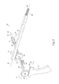
- FIG. 7 is a schematic representation of an actuation assembly in accordance with one non-limiting embodiment.
- FIG. 8 a cross-sectional view of the engagement between the internal shaft of FIG. 7 and the moveable locking member in accordance with one non-limiting embodiment.
- FIG. 9 is a schematic representation of an actuation assembly in accordance with one non-limiting embodiment.
- FIG. 10 is a simplified representation of an actuation assembly in accordance with one non-limiting embodiment.
- FIG. 10A is a close-up view of the damper of FIG. 10 in accordance with one non-limiting embodiment.
- FIG. 11 is a simplified representation of an actuation assembly in accordance with one non-limiting embodiment.
- FIGS. 12-15 illustrate a representation of an electrosurgical instrument comprising a linear actuator in accordance with one non-limiting embodiment.
- FIG. 16 is a block diagram of a control system of an electrosurgical instrument in accordance with one non-limiting embodiment.
- FIG. 17 is a flow chart of the operation of an electrosurgical instrument having a linear actuator in accordance with one non-limiting embodiment.
- FIGS. 18-21 illustrate an electrosurgical instrument having a damper in accordance with one non-limiting embodiment.
- FIG. 18A is an enlarged cross-sectional view of the damper in FIGS. 18-21 .
- FIGS. 22-25 illustrate an electrosurgical instrument with a damper having two check valves
- FIG. 22A is an enlarged cross-sectional view of the damper in FIGS. 22-25 .
- FIG. 26 illustrates a damper that is coupled to a tab of a trigger in accordance with one non-limiting embodiment.
- FIG. 26A is an enlarged view of the damper in FIG. 26 .
- FIG. 27 illustrates a rotary damper in accordance with one non-limiting embodiment.
- FIG. 27A is a cross-sectional view of the damper in FIG. 27 taken along line 27 A- 27 A.
- FIG. 28 illustrates an electrosurgical instrument incorporating an electromagnetic brake assembly in accordance with one non-limiting embodiment.
- FIG. 29 illustrates an electromagnetic brake assembly in accordance with one non-limiting embodiment.
- FIG. 30 illustrates an electromagnetic brake assembly in accordance with one non-limiting embodiment.
- FIG. 31 is a partial cut-away view of an electrosurgical instrument having an electromagnetic brake assembly in accordance with one non-limiting embodiment.
- FIG. 32 illustrates an enlarged view of a brake pad in accordance with one non-limiting embodiment.
- FIGS. 33A and 33B illustrate the electromagnetic brake assembly in FIG. 31 in various stages of operation.
- FIG. 34 is a partial cut-away view of an electrosurgical instrument having an electromagnetic brake assembly in accordance with one non-limiting embodiment.
- FIG. 35 illustrates an electrosurgical instrument having electromagnetic gates to regulate the operational stroke in accordance with one non-limiting embodiment.
- FIGS. 36A , 36 B, and 36 C are enlarged side views of the trigger web and the electromagnet engaging surface in FIG. 35 during an operational stroke in accordance with one non-limiting embodiment.
- FIG. 37 is a partial cut-away view of an electrosurgical instrument having a feedback indicator in accordance with one non-limiting embodiment.
- FIGS. 38A , 38 B, 38 C, and 38 D illustrate the progression of feedback signals provided by the feedback indicator in FIG. 37 in accordance with one non-limiting embodiment.
- tissue “welding” and tissue “fusion” may be used interchangeably herein to describe thermal treatments of a targeted tissue volume that result in a substantially uniform fused-together tissue mass, for example, in welding blood vessels that exhibit substantial burst strength immediately post-treatment.
- the strength of such welds is particularly useful for (i) permanently sealing blood vessels in vessel transection procedures; (ii) welding organ margins in resection procedures; (iii) welding other anatomic ducts wherein permanent closure is required; and also (iv) for performing vessel anastomosis, vessel closure or other procedures that join together anatomic structures or portions thereof.
- tissue as disclosed herein is to be distinguished from “coagulation”, “hemostasis” and other similar descriptive terms that generally relate to the collapse and occlusion of blood flow within small blood vessels or vascularized tissue.
- coagulation any surface application of thermal energy can cause coagulation or hemostasis—but does not fall into the category of “welding” as the term is used herein.
- welding does not create a weld that provides any substantial strength in the treated tissue.
- the phenomena of truly “welding” tissue as disclosed herein may result from the thermally-induced denaturation of collagen and other protein molecules in a targeted tissue volume to create a transient liquid or gel-like proteinaceous amalgam.
- a selected energy density is provided in the targeted tissue to cause hydrothermal breakdown of intra- and intermolecular hydrogen crosslinks in collagen and other proteins.
- the denatured amalgam is maintained at a selected level of hydration—without desiccation—for a selected time interval which can be very brief.
- the targeted tissue volume is maintained under a selected very high level of mechanical compression to insure that the unwound strands of the denatured proteins are in close proximity to allow their intertwining and entanglement.
- the intermixed amalgam results in protein entanglement as re-crosslinking or renaturation occurs to thereby cause a uniform fused-together mass.
- proximal and distal may be used throughout the specification with reference to a clinician manipulating one end of an instrument used to treat a patient.
- proximal refers to the portion of the instrument closest to the clinician and the term “distal” refers to the portion located furthest from the clinician.
- distal refers to the portion located furthest from the clinician.
- spatial terms such as “vertical,” “horizontal,” “up,” and “down” may be used herein with respect to the illustrated embodiments.
- surgical instruments may be used in many orientations and positions, and these terms are not intended to be limiting and absolute.
- Various embodiments disclosed herein provide electrosurgical jaw structures adapted for transecting captured tissue between the jaws and for contemporaneously welding the captured tissue margins with controlled application of RF energy.
- the jaw structures may comprise a scoring element which may cut or score tissue independently of the tissue capturing and welding functions of the jaw structures.
- the jaw structures may comprise first and second opposing jaws that carry positive temperature coefficient (PTC) bodies for modulating RF energy delivery to the engaged tissue.
- PTC positive temperature coefficient
- a surgical instrument can be configured to supply energy, such as electrical energy and/or heat energy, to the tissue of a patient.
- energy such as electrical energy and/or heat energy
- various embodiments disclosed herein provide electrosurgical jaw structures adapted for transecting captured tissue between the jaws and for contemporaneously welding the captured tissue margins with controlled application of RF energy.
- the electrosurgical jaw structures may be adapted to coagulate the captured tissue rather than weld the captured tissue. All such arrangements and implementations are intended to be within the scope of this disclosure.
- the electrosurgical system 100 includes an electrosurgical instrument 101 that may comprise a proximal handle 105 , a distal working end or end effector 110 and an introducer or elongate shaft 108 disposed in-between.
- the end effector 110 may comprise a set of openable-closeable jaws with straight or curved jaws—an upper first jaw 120 A and a lower second jaw 120 B.
- the first jaw 120 A and the second jaw 120 B may each comprise an elongate slot or channel 142 A and 142 B (see FIG. 3 ), respectively, disposed outwardly along their respective middle portions.
- the electrosurgical system 100 can be configured to supply energy, such as electrical energy, ultrasonic energy, and/or heat energy, for example, to the tissue of a patient.
- the electrosurgical system 100 includes a generator 145 in electrical communication with the electrosurgical instrument 101 .
- the generator 145 is connected to electrosurgical instrument 101 via a suitable transmission medium such as a cable 152 .
- the generator 145 is coupled to a controller, such as a control unit 102 , for example.
- the control unit 102 may be formed integrally with the generator 145 or may be provided as a separate circuit module or device electrically coupled to the generator 145 (shown in phantom to illustrate this option).
- the generator 145 is shown separate from the electrosurgical instrument 101 , in one embodiment, the generator 145 (and/or the control unit 102 ) may be formed integrally with the electrosurgical instrument 101 to form a unitary electrosurgical system 100 .
- the generator 145 may comprise an input device 147 located on a front panel of the generator 145 console.
- the input device 147 may comprise any suitable device that generates signals suitable for programming the operation of the generator 145 , such as a keyboard, or input port, for example.
- various electrodes in the first jaw 120 A and the second jaw 120 B may be coupled to the generator 145 .
- a cable 152 may comprise multiple electrical conductors for the application of electrical energy to positive (+) and negative ( ⁇ ) electrodes of the electrosurgical instrument 101 .
- the control unit 102 may be used to activate electrical source 145 .
- the generator 145 may comprise an RF source, an ultrasonic source, a direct current source, and/or any other suitable type of electrical energy source, for example.
- the electrosurgical system 100 may comprise at least one supply conductor 139 and at least one return conductor 141 , wherein current can be supplied to electrosurgical instrument 101 via the supply conductor 139 and wherein the current can flow back to the generator 145 via return conductor 141 .
- the supply conductor 139 and the return conductor 141 may comprise insulated wires and/or any other suitable type of conductor.
- the supply conductor 139 and the return conductor 141 may be contained within and/or may comprise the cable 152 extending between, or at least partially between, the generator 145 and the end effector 110 of the electrosurgical instrument 101 .
- the generator 145 can be configured to apply a sufficient voltage differential between the supply conductor 139 and the return conductor 141 such that sufficient current can be supplied to the end effector 110 .
- the handle 105 may comprise a lever arm 128 (e.g., a trigger) which may be pulled along a path 129 .
- the lever arm 128 may be coupled to an axially moveable member 140 disposed within elongate shaft 108 by a shuttle 146 operably engaged to an extension 127 of lever arm 128 .
- the shuttle 146 may further be connected to a biasing device, such as a spring 141 , which may also be connected to the second handle body 106 B, to bias the shuttle 146 and thus the axially moveable member 140 in a proximal direction, thereby urging the jaws 120 A and 120 B to an open position as seen in FIG. 1 .
- a locking member 131 (see FIG. 2 ) may be moved by a locking switch 130 (see FIG. 1 ) between a locked position, where the shuttle 146 is substantially prevented from moving distally as illustrated, and an unlocked position, where the shuttle 146 may be allowed to freely move in the distal direction, toward the elongate shaft 108 .
- the handle 105 can be any type of pistol-grip or other type of handle known in the art that is configured to carry actuator levers, triggers or sliders for actuating the first jaw 120 A and the second jaw 120 B.
- the elongate shaft 108 may have a cylindrical or rectangular cross-section, for example, and can comprise a thin-wall tubular sleeve that extends from handle 105 .
- the elongate shaft 108 may include a bore extending therethrough for carrying actuator mechanisms, for example, the axially moveable member 140 , for actuating the jaws and for carrying electrical leads for delivery of electrical energy to electrosurgical components of the end effector 110 .
- the end effector 110 may be adapted for capturing and transecting tissue and for the contemporaneously welding the captured tissue with controlled application of energy (e.g., RF energy).
- the first jaw 120 A and the second jaw 120 B may close to thereby capture or engage tissue about a longitudinal axis 125 defined by the axially moveable member 140 .
- the first jaw 120 A and second jaw 120 B may also apply compression to the tissue.
- the elongate shaft 108 along with first jaw 120 A and second jaw 120 B, can be rotated a full 360° degrees, as shown by arrow 117 ( FIG. 1 ), relative to handle 105 through, for example, a rotary triple contact.
- the first jaw 120 A and the second jaw 120 B can remain openable and/or closeable while rotated.
- FIGS. 3 and 4 illustrate perspective views of the end effector 110 in accordance with one non-limiting embodiment.
- FIG. 3 shows end the effector 110 in an open configuration
- FIG. 4 shows the end effector 110 in a closed configuration.
- the end effector 110 may comprise the upper first jaw 120 A and the lower second jaw 120 B.
- the first jaw 120 A and second jaw 120 B may each have tissue-gripping elements, such as teeth 143 , disposed on the inner portions of first jaw 120 A and second jaw 120 B.
- the first jaw 120 A may comprise an upper first jaw body 161 A with an upper first outward-facing surface 162 A and an upper first energy delivery surface 175 A.
- the second jaw 120 B may comprise a lower second jaw body 161 B with a lower second outward-facing surface 162 B and a lower second energy delivery surface 175 B.
- the first energy delivery surface 175 A and the second energy delivery surface 175 B may both extend in a “U” shape about the distal end of the end effector 110 .
- the lever arm 128 of the handle 105 may be adapted to actuate the axially moveable member 140 which also functions as a jaw-closing mechanism.
- the axially moveable member 140 may be urged distally as the lever arm 128 is pulled proximally along the path 129 via the shuttle 146 , as shown in FIG. 2 and discussed above.
- the axially moveable member 140 may comprise one or several pieces, but in any event, may be movable or translatable with respect to the elongate shaft 108 and/or the jaws 120 A, 120 B.
- the axially moveable member 140 may be made of 17-4 precipitation hardened stainless steel.
- the distal end of axially moveable member 140 may comprise a flanged “I”-beam configured to slide within the channels 142 A and 142 B in jaws 120 A and 120 B.
- the axially moveable member 140 may slide within the channels 142 A, 142 B to open and close first jaw 120 A and second jaw 120 B.
- the distal end of the axially moveable member 140 may also comprise an upper flange or “c”-shaped portion 140 A and a lower flange or “c”-shaped portion 140 B.
- the flanges 140 A and 140 B respectively define inner cam surfaces 144 A and 144 B for engaging outward facing surfaces of first jaw 120 A and second jaw 120 B.
- the opening-closing of jaws 120 A and 120 B can apply very high compressive forces on tissue using cam mechanisms which may include movable “I-beam” axially moveable member 140 and the outward facing surfaces 162 A, 162 B of jaws 120 A, 120 B.
- the inner cam surfaces 144 A and 144 B of the distal end of axially moveable member 140 may be adapted to slidably engage the first outward-facing surface 162 A and the second outward-facing surface 162 B of the first jaw 120 A and the second jaw 120 B, respectively.
- the channel 142 A within first jaw 120 A and the channel 142 B within the second jaw 120 B may be sized and configured to accommodate the movement of the axially moveable member 140 , which may comprise a tissue-cutting element 148 , for example, comprising a sharp distal edge.
- the upper first jaw 120 A and lower second jaw 120 B define a gap or dimension D between the first energy delivery surface 175 A and second energy delivery surface 175 B of first jaw 120 A and second jaw 120 B, respectively.
- dimension D can equal from about 0.0005′′ to about 0.040′′, for example, and in some embodiments, between about 0.001′′ to about 0.010′′, for example.
- the edges of the first energy delivery surface 175 A and the second energy delivery surface 175 B may be rounded to prevent the dissection of tissue.
- FIG. 6 is a sectional view of the end effector 110 in accordance with one non-limiting embodiment.
- the engagement, or tissue-contacting, surface 175 B of the lower jaw 120 B is adapted to deliver energy to tissue, at least in part, through a conductive-resistive matrix, such as a variable resistive positive temperature coefficient (PTC) body, as discussed in more detail below.
- a conductive-resistive matrix such as a variable resistive positive temperature coefficient (PTC) body, as discussed in more detail below.
- At least one of the upper and lower jaws 120 A, 120 B may carry at least one electrode 170 configured to deliver the energy from the generator 145 to the captured tissue.
- PTC variable resistive positive temperature coefficient
- the engagement, or tissue-contacting, surface 175 A of upper jaw 120 A may carry a similar conductive-resistive matrix (i.e., a PTC material), or in some embodiments the surface may be a conductive electrode or an insulative layer, for example.
- the engagement surfaces of the jaws can carry any of the energy delivery components disclosed in U.S. Pat. No. 6,773,409, filed Sep. 19, 2001, entitled SURGICAL SYSTEM FOR APPLYING ULTRASONIC ENERGY TO TISSUE, the entire disclosure of which is incorporated herein by reference.
- the first energy delivery surface 175 A and the second energy delivery surface 175 B may each be in electrical communication with the generator 145 .
- the first energy delivery surface 175 A and the second energy delivery surface 175 B may be configured to contact tissue and deliver electrosurgical energy to captured tissue which are adapted to seal or weld the tissue.
- the control unit 102 regulates the electrical energy delivered by electrical generator 145 which in turn delivers electrosurgical energy to the first energy delivery surface 175 A and the second energy delivery surface 175 B.
- the energy delivery may be initiated by an activation button 124 ( FIG. 2 ) operably engaged with the lever arm 128 and in electrical communication with the generator 145 via cable 152 .
- the electrosurgical instrument 101 may be energized by the generator 145 by way of a foot switch 144 ( FIG.
- the foot switch 144 When actuated, the foot switch 144 triggers the generator 145 to deliver electrical energy to the end effector 110 , for example.
- the control unit 102 may regulate the power generated by the generator 145 during activation.
- the foot switch 144 may be suitable in many circumstances, other suitable types of switches can be used.
- the electrosurgical energy delivered by electrical generator 145 and regulated, or otherwise controlled, by the control unit 102 may comprise radio frequency (RF) energy, or other suitable forms of electrical energy.
- RF radio frequency
- the opposing first and second energy delivery surfaces 175 A and 175 B may carry variable resistive positive temperature coefficient (PTC) bodies that are in electrical communication with the generator 145 and the control unit 102 . Additional details regarding electrosurgical end effectors, jaw closing mechanisms, and electrosurgical energy-delivery surfaces are described in the following U.S. patents and published patent applications: U.S. Pat. Nos.
- the generator 145 may be implemented as an electrosurgery unit (ESU) capable of supplying power sufficient to perform bipolar electrosurgery using radio frequency (RF) energy.
- ESU electrosurgery unit
- RF radio frequency
- the ESU can be a bipolar ERBE ICC 350 sold by ERBE USA, Inc. of Marietta, Ga.
- a surgical instrument having an active electrode and a return electrode can be utilized, wherein the active electrode and the return electrode can be positioned against, adjacent to and/or in electrical communication with, the tissue to be treated such that current can flow from the active electrode, through the positive temperature coefficient (PTC) bodies and to the return electrode through the tissue.
- PTC positive temperature coefficient
- the electrosurgical system 100 may comprise a supply path and a return path, wherein the captured tissue being treated completes, or closes, the circuit.
- the generator 145 may be a monopolar RF ESU and the electrosurgical instrument 101 may comprise a monopolar end effector 110 in which one or more active electrodes are integrated.
- the generator 145 may require a return pad in intimate contact with the patient at a location remote from the operative site and/or other suitable return path.
- the return pad may be connected via a cable to the generator 145 .
- the user During operation of electrosurgical instrument 101 , the user generally grasps tissue, supplies energy to the captured tissue to form a weld or a seal, and then drives a tissue-cutting element 148 at the distal end of the axially moveable member 140 through the captured tissue.
- the translation of the axial movement of the axially moveable member 140 may be paced, or otherwise controlled, to aid in driving the axially moveable member 140 at a suitable rate of travel. By controlling the rate of the travel, the likelihood that the captured tissue has been properly and functionally sealed prior to transection with the cutting element 148 is increased.
- FIG. 7 is a schematic representation of an actuation assembly 200 in accordance with one non-limiting embodiment with some of the components thereof omitted for clarity. Additionally various components of the actuation assembly 200 have been expanded or altered in scale for convenience.
- the actuation assembly 200 may be used, for example, with instruments similar to electrosurgical instrument 101 in order to regulate or otherwise control the axial movement of an axially moveable member 240 .
- the actuation assembly 200 may comprise an axially moveable member 240 which has at its distal end 242 a tissue-cutting element, such as a sharp distal edge 243 , for example.
- the axially moveable member 240 may define a longitudinal axis 246 .
- the axially moveable member 240 may also comprise a rack 244 configured to engage a drive gear 246 .
- the drive gear 246 may be coupled to an internal shaft 248 , which may define a longitudinal axis 250 .
- the longitudinal axis 250 of the internal shaft 248 is substantially perpendicular to the longitudinal axis 246 of the axially moveable member 240 .
- a trigger gear 252 may also be coupled to the internal shaft 248 .
- a portion of a trigger assembly 227 may comprise a rack 254 that is configured to engage the trigger gear 252 .
- the actuation assembly 200 may also comprise a moveable locking member 256 this is selectably engagable with the internal shaft 248 or other component of the actuation assembly 200 .
- the actuation assembly 200 may also comprise a spring, such as torsional spring 251 , which distally drives the axially moveable member 240 .
- a spring such as torsional spring 251
- One end of the torsional spring 251 may be coupled to the internal shaft 248 when the other end the torsional spring 251 may be attached to a portion of the actuation assembly 200 that remains stationary relative to the rotating internal shaft 248 .
- Rotation of the internal shaft 248 winds the torsional spring 251 to generate potential energy which may be selectably transferred to the internal shaft 248 , as described in more detail below.
- the internal shaft 248 may comprise a plurality of facets 258 positioned around its circumference.
- the facets 258 may longitudinally span the entire internal shaft 248 , or may be positioned on a portion of the internal shaft 248 , such as the portion proximate the moveable locking member 256 .
- the movable locking member 256 may comprise a pawl 260 that engages the facets 258 of the internal shaft 248 .
- the movable locking member 256 may be able to pivot in the direction indicated by arrow 262 to allow the internal shaft 248 to rotate in a first direction indicated by arrow 264 .
- the internal shaft 248 is prohibited from rotating in a second direction indicated by arrow 266 .
- the pawl 260 is disengaged from the facet 248 , such as by movement of the pawl in the direction indicated by arrow 268 , the internal shaft 248 may rotate in the directions indicated by arrow 266 and arrow 264 .
- the operation of the actuation assembly 200 allows for a controlled distal translation of the axially moveable member 240 .
- the portion of a trigger assembly 227 comprising the rack 254 is moved in the direction indicated by arrow 270 .
- the trigger gear 252 rotates in the direction indicated by arrow 271 .
- the internal shaft 248 rotates as well, which winds the torsional spring 251 .
- the drive gear 246 also rotates in the direction indicated by arrow 271 , which due to its engagement with the rack 244 of the axially moveable member 240 , draws the axially moveable member 240 in the proximal direction indicated by arrow 272 .
- the moveable locking member 256 keeps the internal shaft 248 from rotating in the direction indicated by arrow 274 , despite the rotational force of the torsional spring 251 bearing on the internal shaft 248 .
- the movable locking member 256 may withdraw from engagement with the internal shaft 248 .
- the coupling of the activation button 124 to the movable locking member 256 may be made using any suitable technique, such as a mechanical linkage, for example.
- a tab on the trigger assembly 227 contacts the movable locking member 256 to move it from engagement with the internal shaft 228 once the torsional gear 251 is wound. Accordingly, any suitable technique may be used to disengage the movable locking member 256 from the internal shaft 248 .
- the internal shaft 248 rotates in the direction indicated by arrow 274 as the torsional spring 251 unwinds. Consequently, the drive gear 246 also rotates, and through its engagement with the rack 244 , the axially moveable member 240 is driven in the distal direction indicated by arrow 276 .
- the rate of travel of the axially moveable member 240 is generally dependent on the spring constant of the torsional spring 251 , as opposed to the user's interaction with the trigger.
- the parameters of the components of the actuation assembly 200 may be altered to achieve the desired performance.
- the size or strength of the torsional spring 251 may be changed.
- the gear ratio between the trigger gear 252 and the drive gear 246 may be a 1:1 ratio, while in other embodiments a different ratio is used.
- a single gear 280 may engage both the rack 254 of the trigger assembly 257 and the rack 244 of the axially moveable member 240 .
- a dashpot such as damper 312 ( FIG. 10 ), may be used to further control the translation of axially moveable member 240 .
- FIG. 10 is a simplified representation of an actuation assembly 300 in accordance with one non-limiting embodiment with some of the components thereof omitted for clarity.
- the actuation assembly 300 is associated with a handle 302 and an axially moveable member 306 extending distally from the handle.
- An end effector similar to the end effector 110 illustrated in FIG. 3 may be coupled to the distal end of an elongate shaft 304 .
- the axially moveable member 306 may extend from the end effector and into the handle 302 .
- a trigger 307 is operably coupled to the axially moveable member 306 .
- an advance spring 308 and a return spring 310 are each operably connected to the axially moveable member 306 .
- the advance spring 308 and the return spring 310 may have different spring constants. In one embodiment, the advance spring 308 has a higher spring constant than the return spring 310 .
- the actuation assembly 300 may further comprise a damper 312 configured to regulate (i.e., slow) the translation of the axially moveable member 306 .
- FIG. 10A provides a close-up view of the damper 312 in accordance with one non-limiting embodiment.
- the damper 312 comprises a barrel 314 and a plunger 316 , wherein an outer surface of the plunger 316 is in sealing engagement with an inner surface of the barrel 314 to create a variable volume cavity 315 .
- the damper 312 is illustrated as having a barrel and plunger arrangement, any suitable damping device may be used, such as mechanical or hydraulics dashpots, for example. This disclosure is not limited to any particular damper arrangement.
- the plunger 316 may be coupled to, for example, the proximal end of the axially moveable member 306 .
- the plunger may be movable between a first and second position within the barrel 314 .
- the damper 312 may define a first port 318 having a first flow path and a second port 320 having a second flow path.
- the damper 312 comprises a check valve 322 positioned in the second flow path. During operation, air may flow in both directions through the first flow path, while air may only exit the variable volume cavity 315 through the second flow path.
- the size and number of ports in the barrel 314 may be varied to achieve the desired dampening.
- the trigger 307 may pivot or rotate about a pivot 324 such that as the bottom trigger portion 307 a is rotated in the direction indicated by arrow 326 , the top trigger portion 307 b is rotated in the direction indicated by arrow 328 .
- the top trigger portion 307 b may be coupled to an end of the advance spring 308 .
- the other end of the advance spring 308 may be coupled to the axially moveable member 306 , such as via a linkage 324 .
- One end of the return spring 310 may also be coupled to the axially moveable member 306 , such as via the linkage 324 .
- the other end of the return spring 310 may be fixed to a mount 326 .
- the advance spring 308 and the return spring 310 may exert biasing forces on the axially moveable member 306 in generally opposite longitudinal directions.
- the top trigger portion 307 b exerts a longitudinal force on both the advance spring 308 and the return spring 310 in the direction indicated by arrow 328 .
- the squeezing of the trigger 307 may close the jaws of an associated end effector to capture tissue.
- both springs 308 , 310 expand, the axially moveable member 306 distally translates in order to transect the captured tissue.
- the rate of travel of the axially moveable member 306 is regulated as a function of the spring constants of the springs 308 , 310 and the dampening effects of the damper 312 . Referring to FIG.
- the variable volume cavity 315 expands and a low pressure, below atmosphere, is generated.
- ambient air enters the variable volume cavity 315 through the first port 318 .
- the check valve 322 prohibits air form entering the variable volume cavity 315 through the second port 320 .
- the damping coefficient of the damper 312 is a function of the rate of the ingress of the air through the first port 318 .
- the size of the first port 318 may be variable to provide a selectable damping coefficient.
- the top trigger portion 307 b will continue to exert a substantially linearly applied force on the springs 308 , 310 which continue to expand. Since the advance spring 308 is stronger (i.e., has a higher spring constant) than the return spring 310 , the axially moveable member 306 , via the linkage 324 , will be drawn distally in order to transect captured tissue. As the axially moveable member 306 is translated distally by the force applied through the advance spring 308 , the return spring 310 expands between the linkage 324 and the mount 326 .
- the expanded return spring 310 exerts a linear force on the linkage 324 to proximally translate axially moveable member 306 .
- the proximal translation of the axially moveable member 306 will drive the plunger 316 ( FIG. 10A ) into the barrel 314 , thus reducing the size of the variable volume chamber 315 .
- Air will be expelled from the variable volume chamber 315 via both the first portion 318 and the second port 320 .
- the damping coefficient of the damper 312 is less than when the plunger 316 travels distally.
- the advance spring 308 and the return spring 310 may be any suitable types of biasing members, such as pistons, coil springs, rubber bands, and/or any other suitable elastic member, for example.
- linear compression springs may be used as biasing members.
- FIG. 11 is a simplified representation of an actuation assembly 340 in accordance with one alternative non-limiting embodiment with some of the components thereof omitted for clarity. As illustrated, the actuation assembly 340 may comprise a return spring 342 and an advance spring 344 . The overall operation of the actuation assembly 340 may be generally similar to the operation of the actuation assembly 300 illustrated in FIG. 10 , with the exchange of linear compression springs for linear expansion springs.
- the upper trigger portion 307 b compresses the springs 342 , 344 similar to the above.
- the damper 312 serves to regulate the rate of distal and proximal translation of the axially moveable member 306 .
- the pacing of the axial movement of the axially moveable member may driven by an electric motor or any other type of suitable linearly actuating device, such as an electroactive polymer (EAP) actuator, for example.
- EAP electroactive polymer
- FIGS. 12-15 illustrate a representation of an electrosurgical instrument 400 comprising a linear actuator 402 in accordance with one non-limiting embodiment. For clarity, various components have been omitted.
- the electrosurgical instrument 400 may comprise a proximal handle 405 , a distal working end or end effector 410 and an introducer or elongate shaft 408 disposed in-between.
- An axially moveable member 440 may couple the end effector 410 and a trigger assembly 407 .
- the end effector 410 may comprise a set of openable-closeable jaws with straight or curved jaws, similar to the end effector 110 illustrated in FIG. 3 , for example.
- the linear actuator 402 comprises a lead screw 420 and an electric motor 422 coupled to the lead screw 420 .
- the electric motor 422 may be coupled to a power source 424 via cabling 426 .
- the power supply 424 may be any suitable power source and may be a separate unit (as illustrated), or carried on-board the electrosurgical instrument 400 .
- other techniques may be used to impart linear motion to the axially moveable member 440 .
- the axially moveable member 440 may comprise a rack and the motor 422 may rotate a drive gear operably engaged to the rack.
- a nut assembly 424 may be slideably engaged to the axially moveable member 440 and the lead screw 420 .
- the nut assembly 424 may interface the axially moveable member 440 at a clearance 429 .
- the clearance 429 may be, for example, a portion of the axially moveable member 440 having a reduced diameter.
- Either end of clearance 429 may have a proximal stop 428 and a distal stop 430 .
- the proximal and distal stops 428 , 430 may each be a lip, as illustrated. It is noted that the clearance 429 illustrated in FIGS. 12-15 has been expanded for clarity and is not necessarily drawn to any particular scale. As discussed in more detail below, the clearance 429 generally allows for the opening and closing of the jaws of the end effector 410 , while prohibited the cutting of tissue until the tissue has been properly sealed.
- the trigger assembly 407 may be operatively engaged with axially moveable member 440 at a trigger interface 432 .
- the trigger interface 432 may include a distal sensor 434 and a proximal sensor 436 .
- the trigger interface 432 may also include a distal trigger stop 433 and a proximal trigger stop 435 .
- the electrosurgical instrument 400 may also comprise a button 438 . When the button 438 is engaged, electrical energy (i.e., RF energy) may be supplied to captured tissue via the end effector 410 .
- FIGS. 12-15 the operation of the electrosurgical instrument 400 in accordance with one non-limiting embodiment will be described.
- the jaws of the end effector 410 are in an open position allowing tissue to be captured therebetween.
- a gap 444 is present between the nut assembly 424 and the proximal stop 428 .
- the trigger assembly 407 has been rotated (i.e., squeezed) in the direction indicated by arrow 446 . As the trigger assembly 407 rotates it engages the distal trigger stop 433 which is coupled to the axially moveable member 440 .
- the jaws of the end effector 410 are closed, similar to the end effector 110 illustrated in FIG. 4 .
- the progression of the axially moveable member 440 in the direction indicated by arrow 448 is impeded when the proximal stop 428 engages the nut assembly 424 .
- the distance of travel of axially moveable member 440 is generally limited to the length of the gap 444 ( FIG. 12 ). In one embodiment, this distance is long enough to cause the jaws of the end effector 410 to clamp tissue, while keeping a cutting element at the distal end of the axially moveable member 440 from contacting the captured tissue.
- the clearance 429 may be sized based on the particular arrangement of the electrosurgical instrument 400 .
- the clearance 429 may be less than about 0.5 inches in length as measured between the proximal stop 428 and a distal stop 430 .
- the clearance 429 may be less than about 0.2 inches, for example, in length as measured between the proximal stop 428 and a distal stop 430 .
- the size of the clearance 429 for any electrosurgical instrument 400 will at least partially depend on the relative size of the nut assembly 424 since a gap 444 is required between the nut assembly 424 and the distal stop 430 .
- the button 438 when the button 438 is activated by the user, energy flows through electrodes in the end effector 410 to energize the captured tissue (not illustrated).
- the motor 422 of the linear actuator 402 rotates lead screw 420 in the direction indicated by arrow 450 ( FIG. 15 ).
- the motor 422 will only be activated when both the button 438 is activated to deliver the RF energy to the tissue and the trigger 407 is squeezed.
- the squeezing of the trigger 407 may be sensed by the distal sensor 434 .
- the distal sensor 434 may be, for example, a pressure sensor that supplies a signal to an associated controller.
- the nut assembly 424 travels in the direction indicated by arrow 448 , owing to the operative engagement of threads on the lead screw 420 and a threaded aperture in the nut assembly 424 .
- the nut assembly 424 will engage the axially moveable member 440 at the distal stop 430 .
- the nut assembly 424 will then push the axially moveable member 440 in the distal direction as the user continues to squeeze the trigger 407 and lead screw 420 continues to rotate.
- a cutting element 452 positioned on the distal end of the axially moveable member 440 progresses through and transects the captured tissue.
- the trigger 407 can move toward and activate the proximal sensor 436 .
- Activation of the proximal sensor 436 will cause the motor 422 to rotate the lead screw 420 in the opposite direction, and owing to the threaded engagement between the lead screw 420 and the nut assembly 424 , the nut assembly 424 will translate through the gap 444 ( FIG.
- a controller 502 may be used to receive the inputs from various components of the electrosurgical instrument 440 , such as the button 438 and the sensors 434 , 436 , and selectively supply energy to the motor 422 .
- the speed of the motor 422 may be changed based on any particular application.
- at least one of the proximal sensor 436 and the distal sensor 434 measures the amount of force exerted by the user during the trigger actuation.
- the displacement of the trigger is monitored. In any event, as the force exerted by the user increases (or the displacement of the trigger increases), the speed of the motor 422 is also increased. Therefore, for applications involving large amounts of captured tissue, for example, the user can selectively increase or decrease the speed of the motor through manipulation of the trigger.
- the maximum rate of travel of the axially moveable member 440 is determined by the linear actuator 402 .
- the rate of travel of the axially moveable member 440 may be adjustable by the user.
- the electrosurgical instrument 400 may comprise a force transducer 442 .
- the force transducer 442 may be any type of load cell suitable to produce a signal indicative of the force.
- the force transducer 442 may supply information to the controller indicative to characteristics of the captured tissue. For example, thicker tissue will generally require more time to properly seal and will provide more resistance to the axially moveable member 440 as it passes through the tissue. Comparatively, thinner tissue will generally require less time to properly seal and will provide less resistance to the axially moveable member 440 as it passes through the tissue.
- Information from the force transducer 442 may be supplied to the controller 502 ( FIG. 16 ) and the speed of the motor 422 may be adjusted to compensate for the tissue characteristics. Accordingly, the rotational speed of the lead screw 420 may be reduced when cutting thicker tissue in order to lengthen the amount of time the captured tissue is exposed to the RF energy. The rotational speed of the lead screw 420 may be increased when cutting thinner tissue to shorten the amount of time the captured tissue is exposed to the RF energy and reduce the likelihood of charring or excess heating. In any event, the use of the linear actuator 402 helps to ensure a steady and regulated translation of the axially moveable member through the tissue, even with end effectors having a relatively long jaw length.
- the electrosurgical instrument 440 may have an encoder 460 associated with the linear actuator 402 .
- the encoder 460 may supply information to an associated controller to aid in the cutting of the captured tissue, such as speed data.
- the encoder 460 may be any type of suitable encoder, such as a rotary encoder to monitor the rotation of the lead screw 420 .
- the linear displacement of the axially moveable member 440 may then be determined as a function of the threaded coupling between the nut assembly 424 to the lead screw 420 .
- FIG. 16 is a block diagram of a control system 500 of an electrosurgical instrument in accordance with one non-limiting embodiment.
- a controller 502 receives various inputs from the components, such as an encoder 560 , a force transducer 542 , a button 538 , a distal sensor 534 , and a proximal sensor 536 .
- the controller 502 may send a signal to an RF source 504 which, in turn, provides RF energy to an electrode 506 .
- the controller 502 may supply current to the motor 522 .
- information received from the encoder 560 and the force transducer 542 may provide a feedback loop to aid in the motor control.
- the encoder 560 may indicate that the axially moveable member has reached the distal end of its stroke indicating to the controller 502 to cease supplying current to the motor 522 .
- the controller 502 may rotate the motor 522 in an opposite direction.
- the encoder 560 may indicate that the axially moveable member has reached the proximal of its stroke indicating to the controller 502 to cease supplying current to the motor 522 .
- FIG. 17 is a flow chart 580 of the operation of an electrosurgical instrument having a linear actuator in accordance with one non-limiting embodiment.
- the instrument is in a standby mode. In standby mode, the jaws are in the open position and ready to engage tissue.
- a main trigger such as trigger 407 ( FIG. 14 ) is moved from a first position to a second position in order to capture tissue between the jaws.
- a button such as button 538 , for example, or any other type of triggering or activation device, is activated to supply electrical energy to the captured tissue.
- the main trigger is moved from the second position to a third position to activate a linear actuator and cut the captured tissue.
- an axially moveable member is distally advanced using a linear actuator.
- the main trigger is moved from the third position back to the first position and the linear actuator is activated to move the axially moveable member in the proximal direction to open the jaws of the end effector.
- a dashpot may be coupled to a trigger-actuated axially moveable member in order to regulate the rate of travel of axially moveable member.
- FIGS. 18-21 illustrate an electrosurgical instrument 600 with various components removed, or otherwise simplified, for clarity.
- the electrosurgical instrument 600 has a handle 602 and an elongate shaft 604 extending distally from the handle.
- An end effector 610 similar to the end effector 110 illustrated in FIG. 3 may be coupled to the distal end of the elongate shaft 604 .
- An axially moveable member 606 may extend from the distal end of the elongate shaft 604 into the handle 602 .
- a trigger 607 is coupled to the axially moveable member 606 .
- the electrosurgical instrument 600 may further comprise a damper 612 (shown in cross-section) configured to regulate the translation of the axially moveable member 606 .
- a damper 612 shown in cross-section
- movement of the trigger 607 corresponds to movement of the axially moveable member 606 in the distal and proximal direction due to a pivot 616 and a linkage 614 connecting the trigger 607 to the axially moveable member 606 .
- the damper 612 may be associated with the axially moveable member 606 such that it controls the speed of the axially moveable member 606 during the operational stroke of the electrosurgical instrument 600 .
- FIG. 18A is an enlarged cross-sectional view of the damper 612 in accordance with one non-limiting embodiment.
- the damper 612 comprises a barrel 620 and a plunger 622 , wherein an outer diameter of the plunger 622 is in sealing engagement with an inner diameter of the barrel 620 .
- an o-ring 640 or other type of sealing device may be positioned around the periphery of the plunger 622 to aid in creating a seal with the barrel 620 .
- the plunger 622 may be coupled to the axially moveable member 606 .
- the plunger 622 may be formed unitary with the axially moveable member 606 or otherwise coupled thereto.
- the damper 612 may also have a spring 624 , or other biasing element, to bias the axially moveable member 606 in the proximal direction.
- a spring 624 is positioned intermediate the plunger 622 and a distal end 626 of the damper 612 .
- the distal end 626 may have at least one inlet orifice 628 and at least one outlet orifice 630 .
- the inlet orifice 628 may have a check valve 632 which permits air to flow into the barrel 620 while restricting air to flow out of the barrel 620 through that orifice.
- the check valve 632 may pivot in the direction indicated by arrow 633 .
- the outlet orifice 630 is an open aperture allowing free flow of air (or other fluid) in and out of the barrel 620 .
- the inlet orifice 628 and the outlet orifice 630 may have different cross sectional areas, with the outlet orifice 630 being smaller than the inlet orifice 630 .
- the area of the outlet orifice 630 is variable.
- the distal end 626 may also have a center orifice 634 which is sized to accommodate the axially moveable member 606 .
- a o-ring 636 or other sealing device, may be used to maintain a seal between the distal end 626 of the damper 612 and the axially moveable member 606 .
- the barrel 620 and the distal surface of the plunger 622 define a variable volume cavity 642 . The volume of the variable volume cavity 642 decreases as the plunger 622 is distally translated and increases in volume as the plunger 622 is proximally translated.
- FIG. 18 the electrosurgical instrument 600 is configured to begin the operational stroke.
- the plunger 622 is positioned at the proximal end of the barrel 620 and the jaws of the end effector 610 are in an open position.
- FIG. 19 illustrates the electrosurgical instrument 600 as the trigger 607 is rotated (or squeezed) in the direction indicated by arrow 650 .
- the plunger 622 is translated in the direction indicated by arrow 652 .
- the biasing force of the spring 624 is overcome and the variable volume cavity 642 is reduced in the volume. Air is expelled from the variable volume cavity via the outlet port 630 ( FIG.
- the axially moveable member 606 may continue to distally translate to move the plunger 622 toward the distal end 626 of the barrel 620 .
- the spring 624 is compressed between the plunger 622 and the distal end 626 of the barrel 620 .
- energy may be introduced into the captured tissue to sufficiently weld the tissue prior to and during the operational stroke.
- rotation of the trigger 607 in the direction indicated by arrow 654 translates the plunger 622 in the direction indicated by arrow 656 (e.g., proximally). As the plunger 622 is translated proximally, the volume of the variable volume cavity 642 is increased.
- the increase in volume generates a low pressure which draws air (or other fluid) into the variable volume cavity 642 . Due to the operation of the check valve 632 ( FIG. 18A ), air is permitted to enter the variable volume cavity 642 through both the inlet port 628 and the outlet port 630 . Therefore, the plunger 622 may translate proximally with less resistance as compared to distal translation.
- FIGS. 22-25 illustrates the electrosurgical instrument 600 with a damper 660 having two check valves.
- the spring 624 is positioned external to the damper 660 such that it provides a biasing force to the trigger 607 .
- FIG. 22A is an enlarged cross-sectional view of the damper 660 .
- the damper 660 comprises a barrel 662 which receives the plunger 622 .
- a variable volume cavity 664 is formed between the plunger 622 and the distal end 666 of the barrel 662 .
- the damper 660 further has a first orifice 668 and a second orifice 670 positioned in the distal end 666 of the barrel 662 .
- a first check valve 672 is positioned proximate the first orifice 668 and a second check valve 674 is positioned proximate the second orifice 670 .
- the first check valve 672 defines a first outlet 676 and the second check valve 674 defines a second outlet 678 .
- the check valves 672 , 674 open and air is drawn into the variable volume cavity 664 through the first orifice 668 and the second orifice 670 .
- the total cross-sectional area of the first and second orifices 668 , 670 may be greater than the total cross-sectional area of the first and second outlets 676 , 678 .
- FIG. 26 illustrates an embodiment of a damper 680 that is coupled to a tab 682 of the trigger 607 via a shaft 686 .
- the damper 680 comprises a barrel 688 that may have an inlet port 681 and outlet port 683 arrangement similar to the configuration illustrated in FIG. 18A .
- any suitable configuration of orifices may be used.
- the shaft 686 is coupled to a plunger 684 .
- the shaft 686 and/or the plunger 684 may be integral with the trigger 607 .
- FIG. 26A is an illustration of the damper 680 in accordance with another non-limiting embodiment.
- a sealing member 694 e.g., an o-ring may establish a seal between the shaft 686 and an orifice 695 of the barrel 688 .
- the barrel 688 may be filled with a highly viscous fluid 692 .
- the plunger 684 may separate the barrel 688 into a first cavity 691 and a second cavity 693 . As the plunger 684 is translated within the barrel 688 , one of the cavities increases in volume while the other cavity decreases in volume.
- the highly viscous fluid 692 may flow between the two cavities via a gap 696 between the plunger 684 and the inner wall of the barrel 688 .
- the plunger 684 may have orifices that fluidly couple the first cavity 691 to the second cavity 693 .
- the plunger 684 is translated in the barrel 688 and the highly viscous fluid 692 generally opposes the motion of the plunger 684 to ultimately regulate the translation of the axially moveable member.
- a rotary damper 700 may be used to regulate the movement of an axially moveable member 702 .
- the rotary damper 700 may comprise a sealed volume 704 .
- the sealed volume 704 is a cavity formed within a trigger 706 .
- the trigger may be rotatable about a pivot 708 .
- At least one fin 710 may be fixed with respect to the trigger 706 .
- the fins 710 may radiate from the pivot 708 . While two fins 710 are illustrated in FIG. 27 , it is to be appreciated that any number of fins 710 may be used.
- the fins 710 may be straight, curved, or a combination of straight and curved sections.
- the fins may be attached to inner surface of the 712 of the sealed volume 704 and extend toward the pivot 708 .
- the sealed volume 704 may be filled with a fluid 714 , such as a highly viscous silicone fluid, for example.
- Protrusions 713 may extend into the sealed volume 704 and move relative with respect to the fins 710 during rotation of the trigger 706 .
- the protrusions 713 may be any size or shape.
- FIG. 27A is a cross-sectional view of the damper 700 taken along line 27 A- 27 A.
- the damper 700 is rotatable about a central axis 701 .
- the fins 710 are illustrated in FIG. 27A as being generally rectangular, it is to be appreciated that any suitable shape may be used.
- the fins 710 and/or protrusions 713 may be solid, as illustrated, or may be discontinuous (e.g., vented or perforated) to achieve the desired fluid flow during rotation of the damper 700 .
- a return spring 720 may be coupled to the trigger 706 and the handle 722 in order to urge the trigger 706 to its starting position after it is moved in the direction indicated by arrow 724 .
- the amount of counter force the trigger 706 experiences (e.g., the dampening effect) will depend at least partially on the size of a gap 718 between the pivot 708 and protrusions 713 .
- the faster the trigger 706 is rotated the higher the resistive force supplied by the rotary damper 700 will be. In other words, the resistive force may be proportional to the velocity of the trigger actuation.
- the rotary damper 700 will provide relatively little resistive force. If, however, the user actuates the trigger 706 aggressively, the rotary damper 700 will provide a higher resistive force to slow the trigger actuation 716 .
- the damper may comprise a magnetorheological fluid damper or a solenoid having a variable resistance.
- FIG. 28 illustrates an electrosurgical instrument 800 incorporating an electromagnetic brake assembly 802 in accordance with one non-limiting embodiment.
- the electrosurgical instrument 800 may have an end effector (not illustrated) similar to the end effector 110 illustrated in FIG. 3 coupled to the distal end of an elongate shaft 804 .
- An axially moveable member 806 may extend from the distal end of the elongate shaft 804 into the handle 808 .
- a trigger 810 is coupled to the axially moveable member 806 .
- the trigger 810 comprises a toothed section 812 and the axially moveable member 806 comprises a rack 814 .
- the toothed section 812 of the trigger 810 is engaged to the rack 814 such that rotational movement of the trigger 810 about a pivot 816 is transferred into distal and proximal linear movement of the axially moveable member 806 .
- the rack 814 may have two general sections 818 , 820 .
- the toothed section 812 first engages a first section 818 and the end effector captures and clamps tissue between two jaws, for example.
- a cutting element may be driven through the captured tissue as described in greater detail below.
- the electromagnetic brake assembly 802 may regulate the stroke of the moveable cutting element 806 when the second section 820 of the rack 814 is engaged to the toothed section 812 . By regulating this portion of the stroke, the likelihood of advancing the moveable cutting element 806 too quickly (e.g., before the captured tissue has been sufficiently welded) is reduced.
- Some embodiments may comprise other implementations of electrically actuated brake assemblies.
- the brake assembly may comprise an element that responds to external electrical stimulation by displaying a significant shape or size displacement, such as an electroactive polymer (EAP), for example.
- EAP electroactive polymer
- the brake assembly may comprise a other components, such as a solenoid, a magnetorheological fluid damper, a reed relay, and/or a stepper motor, for example. All such embodiments are intended to be included in this disclosure.
- FIG. 29 is an illustration of the electromagnetic brake assembly 802 in accordance with one non-limiting embodiment.
- the electromagnetic brake assembly 802 may comprise a collar 830 .
- a controller 832 supplies current from a power source 834 a magnetic field around the collar 830 is generated.
- the axially moveable member 806 is positioned proximate the collar 830 and is has a ferrous component, for example, that is attracted to or repulsed by magnetic fields.
- the controller 832 may receive information via an input 836 to determine if a magnetic field should be generated and/or the strength of the magnetic field.
- the input 836 may be an indication of tissue temperature, tissue impedance, or time, for example.
- the electromagnetic brake 802 may be activated. Specifically, a magnetic field may be generated to attract the axially moveable member 806 to the collar 830 . When the axially moveable member 806 is attracted to the collar 830 , the distal progression of the axially moveable member 806 is halted or slowed depending on the intensity of the magnetic field generated. Once the temperature of the captured tissue has reached a sufficient level, the magnetic field of the collar 830 may be reduced or eliminated to allow the axially moveable member 806 to continue its distal translation.
- FIG. 30 is an illustration of an electromagnetic brake assembly 840 in accordance with another non-limiting embodiment.
- a brake element 842 is positioned proximate the trigger 810 .
- a magnetic field is generated which attracts the trigger 810 .
- the brake element 842 may serve to regulate to movement of axially moveable member 806 by selectively engaging the trigger 810 .
- the trigger 810 is attracted to the brake element 842 , the distal progression of the axially moveable member 806 is halted or slowed depending on the intensity of the magnetic field generated.
- FIG. 31 is a partial cut-away view of an electrosurgical instrument 900 having an electromagnetic brake assembly in accordance with one non-limiting embodiment.
- a partial cross-section is provided to illustrate an electromagnetic brake assembly 902 .
- various components have been omitted from the electrosurgical instrument 900 .
- the electrosurgical instrument 900 may have an end effector (not illustrated) similar to the end effector 110 illustrated in FIG. 3 coupled to the distal end of an elongate shaft 904 .
- An axially moveable member 906 may extend from the distal end of the elongate shaft 904 into the handle 908 .
- a trigger 910 is coupled to the axially moveable member 906 .
- the trigger 910 comprises a pivot 912 .
- a surface 914 of the trigger 910 may comprise a series of trigger ridges 916 .
- the trigger ridges 916 radiate outward from the pivot 912 .
- the trigger ridges 916 are dimensioned to engage a brake pad 918 .
- FIG. 32 illustrates an enlarged view of the brake pad 918 .
- the brake pad 918 may comprise pad ridges 920 with troughs 922 positioned intermediate adjacent pad ridges 920 .
- the troughs 922 are dimensioned to receive the trigger ridges 916 .
- the brake pad 918 may be coupled to an electromagnetic solenoid 924 , or other component capable of selectably translating the brake pad 918 between a disengaged position and an engaged position (e.g., an electroactive polymer actuator).
- the solenoid 924 may be energized by a controller 832 ( FIG. 30 ).
- the solenoid 924 When the solenoid 924 is activated, the brake pad 918 is driven toward the trigger ridges 916 such that they engage with the pad ridges 920 .
- the trigger 910 is locked and may not be further rotated by the user.
- the brake pad 918 When the solenoid 924 is de-activated, the brake pad 918 is retracted and the trigger ridges 916 disengage from the pad ridges 920 to allow the trigger 910 to continue its rotation. During operation, the user may simply apply pressure to the trigger 910 and the electromagnetic brake assembly 902 will continually lock and un-lock the trigger 910 in order to regulate the stroke. Similar to the embodiments illustrated in FIGS. 29 and 30 , a controller may use information from various inputs to determine if the trigger 910 should be locked or unlocked.
- the trigger ridges 916 and the brake pad 918 may be made from any suitable material or polymer, such as a thermal set rigid plastic, for example. In some embodiments, the polymer is a nylon or rubber polymer, for example. In other embodiments, the trigger ridges 916 and the brake pad 918 are made from a metal alloy, such as medical grade stainless steel, for example.
- FIGS. 33A and 33B illustrate the electromagnetic brake assembly 902 in various stages of operation.
- the brake pad 918 is coupled to a pad housing 926 that is coupled to the solenoid 924 . While the ridges 916 , 920 are illustrated in a saw tooth configuration, it is appreciated that any suitable type of ridge shapes may be implemented.
- the operation of the solenoid may be controlled by a controller 932 .
- the controller 932 may receive information from a sensor 934 .
- the information may be, for example, tissue temperature information or tissue impedance information.
- the brake pad 918 is separated (i.e., disengaged) from the trigger ridges 916 of the trigger 910 .
- the trigger 910 may rotate with respect to the brake pad 918 .
- the solenoid 924 has translated the brake pad 918 in the direction indicated by arrow 930 .
- the brake pad 918 is engaged to the trigger ridges 916 of the trigger 910 to inhibit the rotation of the trigger 910 with respect to the brake pad 918 .
- This position may be maintained until any number of conditions are satisfied, such as a tissue temperature condition or a time-based condition.
- the brake pad 918 can lock the trigger 910 in position until the temperature and/or impedance of the tissue being treated has exceeded a certain temperature and/or impedance.
- the advancement of movable member 906 , and cutting member associated therewith can be delayed until a sufficient quantity of energy has been supplied to the tissue, as indicated by the sensed temperature and/or impedance. In such circumstances, the tissue may not be incised until the tissue has received a minimum amount of energy.
- the brake can be operated on a time delay, i.e., an amount of time between the initial application of energy to the tissue and the release of the brake.
- FIG. 34 is a partial cut-away view of an electrosurgical instrument having an electromagnetic brake assembly 902 in accordance with one non-limiting embodiment.
- the trigger ridges 916 are positioned around a periphery of the trigger 910 .
- the brake pad 918 is positioned to engage the trigger ridges 916 when the brake pad 918 is moved toward the trigger 910 by the solenoid 924 .
- the brake pad 918 may have a curved portion 920 to mate with the periphery of the trigger 910 .
- FIG. 31 and FIG. 34 illustrate two embodiments of the brake pad 918 , the present disclosure is not limited to any particular brake pad configuration.
- FIG. 35 illustrates an electrosurgical instrument 1000 having electromagnetic gates to regulate the operational stroke.
- the electrosurgical instrument 1000 may have an end effector 1010 similar to the end effector 110 illustrated in FIG. 3 that is coupled to the distal end of an elongate shaft 1004 .
- An axially moveable member 1006 may extend from the distal end of the elongate shaft 1004 into a handle 1002 .
- a trigger 1007 is coupled to the axially moveable member 1006 .
- the trigger 1007 comprises a trigger web 1008 that is received by the handle 1002 during a trigger stroke.
- the electrosurgical instrument 1000 may be electrically coupled to an electrical source 1045 .
- the electrical source 1045 may be connected to the electrosurgical instrument 1000 via a suitable transmission medium such as a cable 1052 .
- the electrical source 1045 is coupled to a controller 1046 .
- the electrosurgical instrument 1000 may comprise an electromagnet engaging surface 1014 positioned proximate the trigger 1007 in the handle 1002 .
- the electromagnet engaging surface 1014 may be ferrous.
- the electrosurgical instrument 1000 may also comprise a plurality of electromagnetic gates 1012 positioned proximate to the trigger 1007 .
- the plurality of electromagnetic gates 1012 are coupled to the trigger web 1008 such that they pass proximate the electromagnet engaging surface 1014 during a trigger stroke.
- the electromagnetic gates 1012 may be selectively magnetized and de-magnetized by the controller 1046 in order to control the trigger actuation during the operational stroke.
- FIGS. 36A-C are enlarged side views of the trigger web 1008 and the electromagnet engaging surface 1014 during an operational stroke in accordance with one non-limiting embodiment.
- electromagnetic gates 1012 a - c are coupled to the trigger web 1008 and are in electrical communication with the controller 1046 via signal lines.
- all of the electromagnetic gates 1012 a - c are energized such that they create a corresponding magnetic field.
- the electromagnet engaging surface 1014 is attracted to the magnetic field of first electromagnetic gate 1012 a .
- the trigger 1007 will remain in this position until the first electromagnetic gate 1012 a is deactivated.
- the user may actuate the trigger 1007 to move the trigger 1007 in the direction indicated by arrow 1016 .
- the electromagnet engaging surface 1014 will then be attracted to the magnetic field of the second electromagnetic gate 1012 b ( FIG. 36B ).
- the trigger 1007 will remain in this position until the second electromagnetic gate 1012 b is deactivated.
- the user may actuate the trigger 1007 to move the trigger 1007 in the direction indicated by arrow 1016 .
- the electromagnet engaging surface 1014 will then be attracted to the magnetic field of the third electromagnetic gate 1012 c ( FIG. 36C ).
- the trigger 1007 will remain in this position until the third electromagnetic gate 1012 c is deactivated. Once the third electromagnetic gate 1012 c is deactivated, the user may actuate the trigger 1007 to move the trigger 1007 in the direction indicated by arrow 1016 to complete the operational stroke, if the operational stroke has not yet been completed.
- FIGS. 36A-C illustrate three electromagnetic gates 1012 a - c
- any number of electromagnetic gates may be used.
- two electromagnetic gates may be used, while in other embodiments, thirty electromagnetic gates may be used, for example.
- various sensors 934 may supply information to the controller 1046 which is used to determine which electromagnetic gates to activate or deactivate.
- Such information may include, for example, tissue temperature information, tissue impedance information, or time delay information.
- the electromagnet engaging surface 1014 may be coupled to the trigger 1007 and the electromagnetic gates 1012 may be coupled to the handle 1002 .
- the advancement of the axially moveable member 1006 can be staggered such that the axially moveable member 1006 can be moved incrementally in the distal direction.
- the movement of the axially movable member 1006 , and a cutting member associated therewith can be delayed until a significant amount of energy has been applied to the tissue being treated. In some circumstances, the tissue may not be incised until the tissue has received a minimum amount of energy.
- the rate in which the axially movable member 1006 may be moved distally may be impeded, or slowed, until a certain amount of energy has been applied, and/or a certain temperature or impedance of the tissue has been reached, wherein, thereafter the axially movable member 1006 may be permitted to move distally at a faster rate or at a rate which is unimpeded by the gates.
- the trigger may be sequentially held at every gate for the same amount of time while, in other embodiments, the trigger may be held at different gates for different amounts of time.
- FIG. 37 is a cut-away view of an electrosurgical instrument 1100 having a feedback indicator 1102 in accordance with one non-limiting embodiment. For the sake of clarity, various components have been omitted from the electrosurgical instrument 1100 .
- the electrosurgical instrument 1100 may have an end effector (not illustrated) similar to the end effector 110 illustrated in FIG. 3 coupled to the distal end of an elongate shaft 1104 .
- An axially moveable member 1106 may extend from the distal end of the elongate shaft 1104 into the handle 1108 .
- a trigger 1110 is coupled to axially moveable member 1106 .
- the trigger 1110 may be a ratcheting trigger that has multiple positions along the operational stroke.
- the trigger 1110 may comprise a hub 1164 that rotates about a pivot 1166 during an operational stroke.
- the hub may define a plurality of notches or detents 1168 that rotate past a pawl 1160 during an operational stroke.
- the pawl 1160 may be biased toward the hub by a spring 1162 .
- the pawl 1160 may comprise, for example, a ball bearing to engage the individual detents 1168 , for example.
- the number of detents 1168 may correspond to the number of discrete trigger positions along the operational stroke.
- the detents 1168 may be evenly spaced around the periphery of the hub 1168 or the distance separating adjacent detents may vary.
- the engagement of the pawl 1160 with the detent 1168 provides tactile feedback to the user.
- the discrete positions may be implemented using a pawl and ratchet, or any other suitable technique.
- the trigger has at five positions (e.g., five detents), for example, although any suitable number of positions may be used.
- the trigger 1110 in a first position 1112 , the trigger 1110 is un-actuated and the jaws on the end effector are open and capable of grasping tissue.
- the axially moveable member 1106 is distally advanced to close the jaws of the end effector.
- energy may be applied to the captured tissue.
- the axially moveable member 1106 has started to transect the captured tissue.
- the axially moveable member 1106 has continued to travel through the captured tissue and at the fifth position 1120 the tissue has been completely transected.
- the operational stroke may have more or less discrete positions, as determined by the number of detents 1168 .
- the feedback indicator 1102 is configured to convey operational information to the user.
- the feedback indicator 1102 is a series of lights (e.g., light emitting diodes).
- the feedback indicator 1102 is positioned proximate the trigger 1110 and provides a vibratory signal to the hand of the user.
- the feedback indicator 1102 is a sound-emitting device that provided audio signals to the user.
- the feedback indicator 1102 is a combination of multiple forms of feedback, such as a tactile and audio, for example.
- the feedback indicator 1102 is located in a position remote from the electrosurgical device 1100 , such as on an external power supply, for example. For illustration purposes only, the operation of the feedback indicator 1102 will be described in the context of a series of lights mounted on the handle 1108 of the electrosurgical instrument 1100 .
- FIGS. 38A-D illustrate the progression of feedback signals provided by the feedback indicator 1102 in accordance with one non-limiting embodiment.
- the feedback indicator comprises a first indicator 1131 , a second indicator 1132 , a third indicator 1133 , and a fourth indicator 1134 .
- indicators, 1131 - 1134 are light emitting diodes (LEDs) which may be toggled between a green indication and a red indication during the operational stroke.
- the LEDs may be white LEDs that are toggled between an on and an off state during an operational stroke.
- other forms of visual indicators may be used, such as an LCD screen, for example.
- the feedback indicator 1102 may be electrically coupled to a controller 1140 .
- the controller 1140 may receive information from a sensor 1148 , such as a tissue impedance sensor.
- the controller 1140 may comprise one or more processors 1142 and one or more computer memories 1146 .
- the processor 1142 may be implemented as an integrated circuit (IC) having one or multiple cores.
- the memory 1146 may comprise volatile and/or non-volatile memory units. Volatile memory units may comprise random access memory (RAM), for example.
- Non-volatile memory units may comprise read only memory (ROM), for example, as well as mechanical non-volatile memory systems, such as, for example, a hard disk drive, an optical disk drive, etc.
- the RAM and/or ROM memory units may be implemented as discrete memory ICs, for example.
- the feedback indicator 1102 may provide information to the user during various stages in the operational stroke. For example, it may provide information to the user which helps the user control the pacing of the operational stroke to increase the likelihood that an adequate tissue seal has been created.
- the feedback indicator 1102 provides feedback when the jaws are closed and the axially moveable member is about to transect the captured tissue (e.g., the second position 1114 ).
- the movement of the trigger 1110 into the second position can be detected by the controller.
- the controller may illuminate the first indicator 1131 .
- the user may apply energy to the captured tissue.
- the user may depress a button 1150 ( FIG. 37 ) positioned on the trigger 1110 .
- the sensor 1148 may monitor a characteristic or property the captured tissue, such as impedance, and when the tissue has reached a certain impedance level, the second indicator 1132 may be illuminated, as illustrated in FIG. 38B .
- the user may actuate the trigger 1110 to the next position (e.g., the third position 1116 ) to begin the cutting stroke.
- the sensor 1148 may continue monitor the characteristic or property the captured tissue, such as impedance, for example, and when the tissue has reached a certain impedance level, the third indicator 1133 may be illuminated, as illustrated in FIG. 38C .
- the user may actuate the trigger 1110 to the next position (e.g., the fourth position 1118 ) to continue its cutting stroke.
- the sensor 1148 may continue monitor the characteristic or property the captured tissue, such as impedance, for example, and when the tissue has reached a certain impedance level, the fourth indicator 1134 may be illuminated, as illustrated in FIG. 38D .
- the user may actuate the trigger 1110 to the next position (e.g., the fifth position 1120 ) to complete its cutting stroke.
- the embodiments of the devices described herein may be introduced inside a patient using minimally invasive or open surgical techniques. In some instances it may be advantageous to introduce the devices inside the patient using a combination of minimally invasive and open surgical techniques. Minimally invasive techniques may provide more accurate and effective access to the treatment region for diagnostic and treatment procedures.
- the devices described herein may be inserted through natural openings of the body such as the mouth, anus, and/or vagina, for example.
- Minimally invasive procedures performed by the introduction of various medical devices into the patient through a natural opening of the patient are known in the art as NOTESTM procedures. Some portions of the devices may be introduced to the tissue treatment region percutaneously or through small-keyhole-incisions.
- Endoscopic minimally invasive surgical and diagnostic medical procedures are used to evaluate and treat internal organs by inserting a small tube into the body.
- the endoscope may have a rigid or a flexible tube.
- a flexible endoscope may be introduced either through a natural body opening (e.g., mouth, anus, and/or vagina) or via a trocar through a relatively small-keyhole-incision incisions (usually 0.5-1.5 cm).
- the endoscope can be used to observe surface conditions of internal organs, including abnormal or diseased tissue such as lesions and other surface conditions and capture images for visual inspection and photography.
- the endoscope may be adapted and configured with working channels for introducing medical instruments to the treatment region for taking biopsies, retrieving foreign objects, and/or performing surgical procedures.
- the devices disclosed herein may be designed to be disposed of after a single use, or they may be designed to be used multiple times. In either case, however, the device may be reconditioned for reuse after at least one use. Reconditioning may include a combination of the steps of disassembly of the device, followed by cleaning or replacement of particular pieces, and subsequent reassembly. In particular, the device may be disassembled, and any number of particular pieces or parts of the device may be selectively replaced or removed in any combination. Upon cleaning and/or replacement of particular parts, the device may be reassembled for subsequent use either at a reconditioning facility, or by a surgical team immediately prior to a surgical procedure.
- reconditioning of a device may utilize a variety of different techniques for disassembly, cleaning/replacement, and reassembly. Use of such techniques, and the resulting reconditioned device, are all within the scope of this application.
- the various embodiments of the devices described herein will be processed before surgery.
- a new or used instrument is obtained and if necessary cleaned.
- the instrument can then be sterilized.
- the instrument is placed in a closed and sealed container, such as a plastic or TYVEK® bag.
- the container and instrument are then placed in a field of radiation that can penetrate the container, such as gamma radiation, x-rays, or high-energy electrons.
- the radiation kills bacteria on the instrument and in the container.
- the sterilized instrument can then be stored in the sterile container.
- the sealed container keeps the instrument sterile until it is opened in the medical facility.
- Other sterilization techniques can be done by any number of ways known to those skilled in the art including beta or gamma radiation, ethylene oxide, and/or steam.
Abstract
Description
Claims (20)
Priority Applications (2)
| Application Number | Priority Date | Filing Date | Title |
|---|---|---|---|
| US12/842,518 US8979844B2 (en) | 2010-07-23 | 2010-07-23 | Electrosurgical cutting and sealing instrument |
| PCT/US2011/044916 WO2012012674A1 (en) | 2010-07-23 | 2011-07-22 | Electrosurgical cutting and sealing instrument |
Applications Claiming Priority (1)
| Application Number | Priority Date | Filing Date | Title |
|---|---|---|---|
| US12/842,518 US8979844B2 (en) | 2010-07-23 | 2010-07-23 | Electrosurgical cutting and sealing instrument |
Publications (2)
| Publication Number | Publication Date |
|---|---|
| US20120022528A1 US20120022528A1 (en) | 2012-01-26 |
| US8979844B2 true US8979844B2 (en) | 2015-03-17 |
Family
ID=45494211
Family Applications (1)
| Application Number | Title | Priority Date | Filing Date |
|---|---|---|---|
| US12/842,518 Active 2032-10-15 US8979844B2 (en) | 2010-07-23 | 2010-07-23 | Electrosurgical cutting and sealing instrument |
Country Status (1)
| Country | Link |
|---|---|
| US (1) | US8979844B2 (en) |
Cited By (150)
| Publication number | Priority date | Publication date | Assignee | Title |
|---|---|---|---|---|
| US9265926B2 (en) | 2013-11-08 | 2016-02-23 | Ethicon Endo-Surgery, Llc | Electrosurgical devices |
| US9283027B2 (en) | 2011-10-24 | 2016-03-15 | Ethicon Endo-Surgery, Llc | Battery drain kill feature in a battery powered device |
| US9295514B2 (en) | 2013-08-30 | 2016-03-29 | Ethicon Endo-Surgery, Llc | Surgical devices with close quarter articulation features |
| US9456864B2 (en) | 2010-05-17 | 2016-10-04 | Ethicon Endo-Surgery, Llc | Surgical instruments and end effectors therefor |
| US9492224B2 (en) | 2012-09-28 | 2016-11-15 | EthiconEndo-Surgery, LLC | Multi-function bi-polar forceps |
| US9526565B2 (en) | 2013-11-08 | 2016-12-27 | Ethicon Endo-Surgery, Llc | Electrosurgical devices |
| US9554846B2 (en) | 2010-10-01 | 2017-01-31 | Ethicon Endo-Surgery, Llc | Surgical instrument with jaw member |
| US9554854B2 (en) | 2014-03-18 | 2017-01-31 | Ethicon Endo-Surgery, Llc | Detecting short circuits in electrosurgical medical devices |
| US9610091B2 (en) | 2010-04-12 | 2017-04-04 | Ethicon Endo-Surgery, Llc | Electrosurgical cutting and sealing instruments with jaws having a parallel closure motion |
| US9700333B2 (en) | 2014-06-30 | 2017-07-11 | Ethicon Llc | Surgical instrument with variable tissue compression |
| US9737358B2 (en) | 2010-06-10 | 2017-08-22 | Ethicon Llc | Heat management configurations for controlling heat dissipation from electrosurgical instruments |
| US9737355B2 (en) | 2014-03-31 | 2017-08-22 | Ethicon Llc | Controlling impedance rise in electrosurgical medical devices |
| US9757186B2 (en) | 2014-04-17 | 2017-09-12 | Ethicon Llc | Device status feedback for bipolar tissue spacer |
| US9795436B2 (en) | 2014-01-07 | 2017-10-24 | Ethicon Llc | Harvesting energy from a surgical generator |
| US9808308B2 (en) | 2010-04-12 | 2017-11-07 | Ethicon Llc | Electrosurgical cutting and sealing instruments with cam-actuated jaws |
| US9814514B2 (en) | 2013-09-13 | 2017-11-14 | Ethicon Llc | Electrosurgical (RF) medical instruments for cutting and coagulating tissue |
| US9848937B2 (en) | 2014-12-22 | 2017-12-26 | Ethicon Llc | End effector with detectable configurations |
| US9872725B2 (en) | 2015-04-29 | 2018-01-23 | Ethicon Llc | RF tissue sealer with mode selection |
| US9877776B2 (en) | 2014-08-25 | 2018-01-30 | Ethicon Llc | Simultaneous I-beam and spring driven cam jaw closure mechanism |
| US9913680B2 (en) | 2014-04-15 | 2018-03-13 | Ethicon Llc | Software algorithms for electrosurgical instruments |
| US10092310B2 (en) | 2014-03-27 | 2018-10-09 | Ethicon Llc | Electrosurgical devices |
| US10092348B2 (en) | 2014-12-22 | 2018-10-09 | Ethicon Llc | RF tissue sealer, shear grip, trigger lock mechanism and energy activation |
| US10111699B2 (en) | 2014-12-22 | 2018-10-30 | Ethicon Llc | RF tissue sealer, shear grip, trigger lock mechanism and energy activation |
| US10117702B2 (en) | 2015-04-10 | 2018-11-06 | Ethicon Llc | Surgical generator systems and related methods |
| US10117667B2 (en) | 2010-02-11 | 2018-11-06 | Ethicon Llc | Control systems for ultrasonically powered surgical instruments |
| US10130410B2 (en) | 2015-04-17 | 2018-11-20 | Ethicon Llc | Electrosurgical instrument including a cutting member decouplable from a cutting member trigger |
| US10154852B2 (en) | 2015-07-01 | 2018-12-18 | Ethicon Llc | Ultrasonic surgical blade with improved cutting and coagulation features |
| US10159524B2 (en) | 2014-12-22 | 2018-12-25 | Ethicon Llc | High power battery powered RF amplifier topology |
| US10166060B2 (en) | 2011-08-30 | 2019-01-01 | Ethicon Llc | Surgical instruments comprising a trigger assembly |
| US10179022B2 (en) | 2015-12-30 | 2019-01-15 | Ethicon Llc | Jaw position impedance limiter for electrosurgical instrument |
| US10194972B2 (en) | 2014-08-26 | 2019-02-05 | Ethicon Llc | Managing tissue treatment |
| US10194976B2 (en) | 2014-08-25 | 2019-02-05 | Ethicon Llc | Lockout disabling mechanism |
| US10194973B2 (en) | 2015-09-30 | 2019-02-05 | Ethicon Llc | Generator for digitally generating electrical signal waveforms for electrosurgical and ultrasonic surgical instruments |
| US10201382B2 (en) | 2009-10-09 | 2019-02-12 | Ethicon Llc | Surgical generator for ultrasonic and electrosurgical devices |
| US10226273B2 (en) | 2013-03-14 | 2019-03-12 | Ethicon Llc | Mechanical fasteners for use with surgical energy devices |
| US10245064B2 (en) | 2016-07-12 | 2019-04-02 | Ethicon Llc | Ultrasonic surgical instrument with piezoelectric central lumen transducer |
| US10245065B2 (en) | 2007-11-30 | 2019-04-02 | Ethicon Llc | Ultrasonic surgical blades |
| US10251664B2 (en) | 2016-01-15 | 2019-04-09 | Ethicon Llc | Modular battery powered handheld surgical instrument with multi-function motor via shifting gear assembly |
| USD847990S1 (en) | 2016-08-16 | 2019-05-07 | Ethicon Llc | Surgical instrument |
| US10278721B2 (en) | 2010-07-22 | 2019-05-07 | Ethicon Llc | Electrosurgical instrument with separate closure and cutting members |
| US10285723B2 (en) | 2016-08-09 | 2019-05-14 | Ethicon Llc | Ultrasonic surgical blade with improved heel portion |
| US10285724B2 (en) | 2014-07-31 | 2019-05-14 | Ethicon Llc | Actuation mechanisms and load adjustment assemblies for surgical instruments |
| US10299810B2 (en) | 2010-02-11 | 2019-05-28 | Ethicon Llc | Rotatable cutting implements with friction reducing material for ultrasonic surgical instruments |
| US10314638B2 (en) | 2015-04-07 | 2019-06-11 | Ethicon Llc | Articulating radio frequency (RF) tissue seal with articulating state sensing |
| US10321950B2 (en) | 2015-03-17 | 2019-06-18 | Ethicon Llc | Managing tissue treatment |
| US10335614B2 (en) | 2008-08-06 | 2019-07-02 | Ethicon Llc | Devices and techniques for cutting and coagulating tissue |
| US10335182B2 (en) | 2012-06-29 | 2019-07-02 | Ethicon Llc | Surgical instruments with articulating shafts |
| US10335183B2 (en) | 2012-06-29 | 2019-07-02 | Ethicon Llc | Feedback devices for surgical control systems |
| US10342602B2 (en) | 2015-03-17 | 2019-07-09 | Ethicon Llc | Managing tissue treatment |
| US10357303B2 (en) | 2015-06-30 | 2019-07-23 | Ethicon Llc | Translatable outer tube for sealing using shielded lap chole dissector |
| US10376305B2 (en) | 2016-08-05 | 2019-08-13 | Ethicon Llc | Methods and systems for advanced harmonic energy |
| US10398466B2 (en) | 2007-07-27 | 2019-09-03 | Ethicon Llc | Ultrasonic end effectors with increased active length |
| US10420580B2 (en) | 2016-08-25 | 2019-09-24 | Ethicon Llc | Ultrasonic transducer for surgical instrument |
| US10420579B2 (en) | 2007-07-31 | 2019-09-24 | Ethicon Llc | Surgical instruments |
| US10426507B2 (en) | 2007-07-31 | 2019-10-01 | Ethicon Llc | Ultrasonic surgical instruments |
| US10433900B2 (en) | 2011-07-22 | 2019-10-08 | Ethicon Llc | Surgical instruments for tensioning tissue |
| US10441308B2 (en) | 2007-11-30 | 2019-10-15 | Ethicon Llc | Ultrasonic surgical instrument blades |
| US10441310B2 (en) | 2012-06-29 | 2019-10-15 | Ethicon Llc | Surgical instruments with curved section |
| US10441345B2 (en) | 2009-10-09 | 2019-10-15 | Ethicon Llc | Surgical generator for ultrasonic and electrosurgical devices |
| US10456193B2 (en) | 2016-05-03 | 2019-10-29 | Ethicon Llc | Medical device with a bilateral jaw configuration for nerve stimulation |
| US10463421B2 (en) | 2014-03-27 | 2019-11-05 | Ethicon Llc | Two stage trigger, clamp and cut bipolar vessel sealer |
| US10485607B2 (en) | 2016-04-29 | 2019-11-26 | Ethicon Llc | Jaw structure with distal closure for electrosurgical instruments |
| US10517627B2 (en) | 2012-04-09 | 2019-12-31 | Ethicon Llc | Switch arrangements for ultrasonic surgical instruments |
| US10524852B1 (en) | 2014-03-28 | 2020-01-07 | Ethicon Llc | Distal sealing end effector with spacers |
| US10524854B2 (en) | 2010-07-23 | 2020-01-07 | Ethicon Llc | Surgical instrument |
| US10524872B2 (en) | 2012-06-29 | 2020-01-07 | Ethicon Llc | Closed feedback control for electrosurgical device |
| US10531910B2 (en) | 2007-07-27 | 2020-01-14 | Ethicon Llc | Surgical instruments |
| US10537352B2 (en) | 2004-10-08 | 2020-01-21 | Ethicon Llc | Tissue pads for use with surgical instruments |
| US10543008B2 (en) | 2012-06-29 | 2020-01-28 | Ethicon Llc | Ultrasonic surgical instruments with distally positioned jaw assemblies |
| US10555769B2 (en) | 2016-02-22 | 2020-02-11 | Ethicon Llc | Flexible circuits for electrosurgical instrument |
| US10575892B2 (en) | 2015-12-31 | 2020-03-03 | Ethicon Llc | Adapter for electrical surgical instruments |
| US10595929B2 (en) | 2015-03-24 | 2020-03-24 | Ethicon Llc | Surgical instruments with firing system overload protection mechanisms |
| US10595930B2 (en) | 2015-10-16 | 2020-03-24 | Ethicon Llc | Electrode wiping surgical device |
| US10603064B2 (en) | 2016-11-28 | 2020-03-31 | Ethicon Llc | Ultrasonic transducer |
| US10603117B2 (en) | 2017-06-28 | 2020-03-31 | Ethicon Llc | Articulation state detection mechanisms |
| US10639092B2 (en) | 2014-12-08 | 2020-05-05 | Ethicon Llc | Electrode configurations for surgical instruments |
| US10646269B2 (en) | 2016-04-29 | 2020-05-12 | Ethicon Llc | Non-linear jaw gap for electrosurgical instruments |
| US10688321B2 (en) | 2009-07-15 | 2020-06-23 | Ethicon Llc | Ultrasonic surgical instruments |
| US10702329B2 (en) | 2016-04-29 | 2020-07-07 | Ethicon Llc | Jaw structure with distal post for electrosurgical instruments |
| US10709906B2 (en) | 2009-05-20 | 2020-07-14 | Ethicon Llc | Coupling arrangements and methods for attaching tools to ultrasonic surgical instruments |
| US10716615B2 (en) | 2016-01-15 | 2020-07-21 | Ethicon Llc | Modular battery powered handheld surgical instrument with curved end effectors having asymmetric engagement between jaw and blade |
| US10722261B2 (en) | 2007-03-22 | 2020-07-28 | Ethicon Llc | Surgical instruments |
| US10729494B2 (en) | 2012-02-10 | 2020-08-04 | Ethicon Llc | Robotically controlled surgical instrument |
| US10751117B2 (en) | 2016-09-23 | 2020-08-25 | Ethicon Llc | Electrosurgical instrument with fluid diverter |
| US10765470B2 (en) | 2015-06-30 | 2020-09-08 | Ethicon Llc | Surgical system with user adaptable techniques employing simultaneous energy modalities based on tissue parameters |
| US10779848B2 (en) | 2006-01-20 | 2020-09-22 | Ethicon Llc | Ultrasound medical instrument having a medical ultrasonic blade |
| US10779845B2 (en) | 2012-06-29 | 2020-09-22 | Ethicon Llc | Ultrasonic surgical instruments with distally positioned transducers |
| US10799284B2 (en) | 2017-03-15 | 2020-10-13 | Ethicon Llc | Electrosurgical instrument with textured jaws |
| US10820920B2 (en) | 2017-07-05 | 2020-11-03 | Ethicon Llc | Reusable ultrasonic medical devices and methods of their use |
| US10828057B2 (en) | 2007-03-22 | 2020-11-10 | Ethicon Llc | Ultrasonic surgical instruments |
| US10828059B2 (en) | 2007-10-05 | 2020-11-10 | Ethicon Llc | Ergonomic surgical instruments |
| US10835768B2 (en) | 2010-02-11 | 2020-11-17 | Ethicon Llc | Dual purpose surgical instrument for cutting and coagulating tissue |
| US10835307B2 (en) | 2001-06-12 | 2020-11-17 | Ethicon Llc | Modular battery powered handheld surgical instrument containing elongated multi-layered shaft |
| US10842522B2 (en) | 2016-07-15 | 2020-11-24 | Ethicon Llc | Ultrasonic surgical instruments having offset blades |
| US10842580B2 (en) | 2012-06-29 | 2020-11-24 | Ethicon Llc | Ultrasonic surgical instruments with control mechanisms |
| US10856934B2 (en) | 2016-04-29 | 2020-12-08 | Ethicon Llc | Electrosurgical instrument with electrically conductive gap setting and tissue engaging members |
| US10856896B2 (en) | 2005-10-14 | 2020-12-08 | Ethicon Llc | Ultrasonic device for cutting and coagulating |
| US10874418B2 (en) | 2004-02-27 | 2020-12-29 | Ethicon Llc | Ultrasonic surgical shears and method for sealing a blood vessel using same |
| US10893883B2 (en) | 2016-07-13 | 2021-01-19 | Ethicon Llc | Ultrasonic assembly for use with ultrasonic surgical instruments |
| US10898256B2 (en) | 2015-06-30 | 2021-01-26 | Ethicon Llc | Surgical system with user adaptable techniques based on tissue impedance |
| US10912580B2 (en) | 2013-12-16 | 2021-02-09 | Ethicon Llc | Medical device |
| US10952759B2 (en) | 2016-08-25 | 2021-03-23 | Ethicon Llc | Tissue loading of a surgical instrument |
| US10952788B2 (en) | 2015-06-30 | 2021-03-23 | Ethicon Llc | Surgical instrument with user adaptable algorithms |
| US10959771B2 (en) | 2015-10-16 | 2021-03-30 | Ethicon Llc | Suction and irrigation sealing grasper |
| US10959806B2 (en) | 2015-12-30 | 2021-03-30 | Ethicon Llc | Energized medical device with reusable handle |
| US10987123B2 (en) | 2012-06-28 | 2021-04-27 | Ethicon Llc | Surgical instruments with articulating shafts |
| US10987156B2 (en) | 2016-04-29 | 2021-04-27 | Ethicon Llc | Electrosurgical instrument with electrically conductive gap setting member and electrically insulative tissue engaging members |
| US10993763B2 (en) | 2012-06-29 | 2021-05-04 | Ethicon Llc | Lockout mechanism for use with robotic electrosurgical device |
| US11020140B2 (en) | 2015-06-17 | 2021-06-01 | Cilag Gmbh International | Ultrasonic surgical blade for use with ultrasonic surgical instruments |
| US11033292B2 (en) | 2013-12-16 | 2021-06-15 | Cilag Gmbh International | Medical device |
| US11033325B2 (en) | 2017-02-16 | 2021-06-15 | Cilag Gmbh International | Electrosurgical instrument with telescoping suction port and debris cleaner |
| US11033323B2 (en) | 2017-09-29 | 2021-06-15 | Cilag Gmbh International | Systems and methods for managing fluid and suction in electrosurgical systems |
| US11051873B2 (en) | 2015-06-30 | 2021-07-06 | Cilag Gmbh International | Surgical system with user adaptable techniques employing multiple energy modalities based on tissue parameters |
| US11058447B2 (en) | 2007-07-31 | 2021-07-13 | Cilag Gmbh International | Temperature controlled ultrasonic surgical instruments |
| US11090103B2 (en) | 2010-05-21 | 2021-08-17 | Cilag Gmbh International | Medical device |
| US11090104B2 (en) | 2009-10-09 | 2021-08-17 | Cilag Gmbh International | Surgical generator for ultrasonic and electrosurgical devices |
| US11129670B2 (en) | 2016-01-15 | 2021-09-28 | Cilag Gmbh International | Modular battery powered handheld surgical instrument with selective application of energy based on button displacement, intensity, or local tissue characterization |
| US11129669B2 (en) | 2015-06-30 | 2021-09-28 | Cilag Gmbh International | Surgical system with user adaptable techniques based on tissue type |
| US11179173B2 (en) | 2012-10-22 | 2021-11-23 | Cilag Gmbh International | Surgical instrument |
| US11229471B2 (en) | 2016-01-15 | 2022-01-25 | Cilag Gmbh International | Modular battery powered handheld surgical instrument with selective application of energy based on tissue characterization |
| US11266430B2 (en) | 2016-11-29 | 2022-03-08 | Cilag Gmbh International | End effector control and calibration |
| US11311326B2 (en) | 2015-02-06 | 2022-04-26 | Cilag Gmbh International | Electrosurgical instrument with rotation and articulation mechanisms |
| US11324527B2 (en) | 2012-11-15 | 2022-05-10 | Cilag Gmbh International | Ultrasonic and electrosurgical devices |
| US11413102B2 (en) | 2019-06-27 | 2022-08-16 | Cilag Gmbh International | Multi-access port for surgical robotic systems |
| US11452525B2 (en) | 2019-12-30 | 2022-09-27 | Cilag Gmbh International | Surgical instrument comprising an adjustment system |
| US11484358B2 (en) | 2017-09-29 | 2022-11-01 | Cilag Gmbh International | Flexible electrosurgical instrument |
| US11490951B2 (en) | 2017-09-29 | 2022-11-08 | Cilag Gmbh International | Saline contact with electrodes |
| US11497546B2 (en) | 2017-03-31 | 2022-11-15 | Cilag Gmbh International | Area ratios of patterned coatings on RF electrodes to reduce sticking |
| US11523859B2 (en) | 2012-06-28 | 2022-12-13 | Cilag Gmbh International | Surgical instrument assembly including a removably attachable end effector |
| US11547468B2 (en) | 2019-06-27 | 2023-01-10 | Cilag Gmbh International | Robotic surgical system with safety and cooperative sensing control |
| US11589916B2 (en) | 2019-12-30 | 2023-02-28 | Cilag Gmbh International | Electrosurgical instruments with electrodes having variable energy densities |
| US11607278B2 (en) | 2019-06-27 | 2023-03-21 | Cilag Gmbh International | Cooperative robotic surgical systems |
| US11612445B2 (en) | 2019-06-27 | 2023-03-28 | Cilag Gmbh International | Cooperative operation of robotic arms |
| US11660089B2 (en) | 2019-12-30 | 2023-05-30 | Cilag Gmbh International | Surgical instrument comprising a sensing system |
| US11684412B2 (en) | 2019-12-30 | 2023-06-27 | Cilag Gmbh International | Surgical instrument with rotatable and articulatable surgical end effector |
| US11696776B2 (en) | 2019-12-30 | 2023-07-11 | Cilag Gmbh International | Articulatable surgical instrument |
| US11723729B2 (en) | 2019-06-27 | 2023-08-15 | Cilag Gmbh International | Robotic surgical assembly coupling safety mechanisms |
| US11723716B2 (en) | 2019-12-30 | 2023-08-15 | Cilag Gmbh International | Electrosurgical instrument with variable control mechanisms |
| US11759251B2 (en) | 2019-12-30 | 2023-09-19 | Cilag Gmbh International | Control program adaptation based on device status and user input |
| US11779387B2 (en) | 2019-12-30 | 2023-10-10 | Cilag Gmbh International | Clamp arm jaw to minimize tissue sticking and improve tissue control |
| US11779329B2 (en) | 2019-12-30 | 2023-10-10 | Cilag Gmbh International | Surgical instrument comprising a flex circuit including a sensor system |
| US11786291B2 (en) | 2019-12-30 | 2023-10-17 | Cilag Gmbh International | Deflectable support of RF energy electrode with respect to opposing ultrasonic blade |
| US11812957B2 (en) | 2019-12-30 | 2023-11-14 | Cilag Gmbh International | Surgical instrument comprising a signal interference resolution system |
| US11911063B2 (en) | 2019-12-30 | 2024-02-27 | Cilag Gmbh International | Techniques for detecting ultrasonic blade to electrode contact and reducing power to ultrasonic blade |
| US11931026B2 (en) | 2021-06-30 | 2024-03-19 | Cilag Gmbh International | Staple cartridge replacement |
| US11937863B2 (en) | 2019-12-30 | 2024-03-26 | Cilag Gmbh International | Deflectable electrode with variable compression bias along the length of the deflectable electrode |
| US11937866B2 (en) | 2019-12-30 | 2024-03-26 | Cilag Gmbh International | Method for an electrosurgical procedure |
| US11944366B2 (en) | 2019-12-30 | 2024-04-02 | Cilag Gmbh International | Asymmetric segmented ultrasonic support pad for cooperative engagement with a movable RF electrode |
| US11950797B2 (en) | 2019-12-30 | 2024-04-09 | Cilag Gmbh International | Deflectable electrode with higher distal bias relative to proximal bias |
| US11957342B2 (en) | 2021-11-01 | 2024-04-16 | Cilag Gmbh International | Devices, systems, and methods for detecting tissue and foreign objects during a surgical operation |
Families Citing this family (24)
| Publication number | Priority date | Publication date | Assignee | Title |
|---|---|---|---|---|
| US8747404B2 (en) * | 2009-10-09 | 2014-06-10 | Ethicon Endo-Surgery, Inc. | Surgical instrument for transmitting energy to tissue comprising non-conductive grasping portions |
| US8939974B2 (en) * | 2009-10-09 | 2015-01-27 | Ethicon Endo-Surgery, Inc. | Surgical instrument comprising first and second drive systems actuatable by a common trigger mechanism |
| US8906016B2 (en) * | 2009-10-09 | 2014-12-09 | Ethicon Endo-Surgery, Inc. | Surgical instrument for transmitting energy to tissue comprising steam control paths |
| US8574231B2 (en) * | 2009-10-09 | 2013-11-05 | Ethicon Endo-Surgery, Inc. | Surgical instrument for transmitting energy to tissue comprising a movable electrode or insulator |
| US10172669B2 (en) * | 2009-10-09 | 2019-01-08 | Ethicon Llc | Surgical instrument comprising an energy trigger lockout |
| US8696665B2 (en) | 2010-03-26 | 2014-04-15 | Ethicon Endo-Surgery, Inc. | Surgical cutting and sealing instrument with reduced firing force |
| US8496682B2 (en) | 2010-04-12 | 2013-07-30 | Ethicon Endo-Surgery, Inc. | Electrosurgical cutting and sealing instruments with cam-actuated jaws |
| US8535311B2 (en) | 2010-04-22 | 2013-09-17 | Ethicon Endo-Surgery, Inc. | Electrosurgical instrument comprising closing and firing systems |
| US8790342B2 (en) | 2010-06-09 | 2014-07-29 | Ethicon Endo-Surgery, Inc. | Electrosurgical instrument employing pressure-variation electrodes |
| US8888776B2 (en) | 2010-06-09 | 2014-11-18 | Ethicon Endo-Surgery, Inc. | Electrosurgical instrument employing an electrode |
| US8926607B2 (en) | 2010-06-09 | 2015-01-06 | Ethicon Endo-Surgery, Inc. | Electrosurgical instrument employing multiple positive temperature coefficient electrodes |
| US8795276B2 (en) | 2010-06-09 | 2014-08-05 | Ethicon Endo-Surgery, Inc. | Electrosurgical instrument employing a plurality of electrodes |
| US8764747B2 (en) | 2010-06-10 | 2014-07-01 | Ethicon Endo-Surgery, Inc. | Electrosurgical instrument comprising sequentially activated electrodes |
| US8753338B2 (en) | 2010-06-10 | 2014-06-17 | Ethicon Endo-Surgery, Inc. | Electrosurgical instrument employing a thermal management system |
| US9149324B2 (en) | 2010-07-08 | 2015-10-06 | Ethicon Endo-Surgery, Inc. | Surgical instrument comprising an articulatable end effector |
| US8613383B2 (en) | 2010-07-14 | 2013-12-24 | Ethicon Endo-Surgery, Inc. | Surgical instruments with electrodes |
| US8453906B2 (en) | 2010-07-14 | 2013-06-04 | Ethicon Endo-Surgery, Inc. | Surgical instruments with electrodes |
| US9011437B2 (en) | 2010-07-23 | 2015-04-21 | Ethicon Endo-Surgery, Inc. | Electrosurgical cutting and sealing instrument |
| US8979843B2 (en) | 2010-07-23 | 2015-03-17 | Ethicon Endo-Surgery, Inc. | Electrosurgical cutting and sealing instrument |
| US8702704B2 (en) | 2010-07-23 | 2014-04-22 | Ethicon Endo-Surgery, Inc. | Electrosurgical cutting and sealing instrument |
| US8628529B2 (en) | 2010-10-26 | 2014-01-14 | Ethicon Endo-Surgery, Inc. | Surgical instrument with magnetic clamping force |
| US8715277B2 (en) | 2010-12-08 | 2014-05-06 | Ethicon Endo-Surgery, Inc. | Control of jaw compression in surgical instrument having end effector with opposing jaw members |
| US9861428B2 (en) | 2013-09-16 | 2018-01-09 | Ethicon Llc | Integrated systems for electrosurgical steam or smoke control |
| US9408660B2 (en) | 2014-01-17 | 2016-08-09 | Ethicon Endo-Surgery, Llc | Device trigger dampening mechanism |
Citations (187)
| Publication number | Priority date | Publication date | Assignee | Title |
|---|---|---|---|---|
| US3580841A (en) | 1969-07-31 | 1971-05-25 | Us Interior | Ultrathin semipermeable membrane |
| US3703651A (en) | 1971-07-12 | 1972-11-21 | Kollmorgen Corp | Temperature-controlled integrated circuits |
| US4005714A (en) | 1975-05-03 | 1977-02-01 | Richard Wolf Gmbh | Bipolar coagulation forceps |
| US4058126A (en) | 1973-08-02 | 1977-11-15 | Leveen Harry H | Device for the fracture of the blood vessel lining |
| US4237441A (en) | 1978-12-01 | 1980-12-02 | Raychem Corporation | Low resistivity PTC compositions |
| US4304987A (en) | 1978-09-18 | 1981-12-08 | Raychem Corporation | Electrical devices comprising conductive polymer compositions |
| US4535773A (en) | 1982-03-26 | 1985-08-20 | Inbae Yoon | Safety puncturing instrument and method |
| US4545926A (en) | 1980-04-21 | 1985-10-08 | Raychem Corporation | Conductive polymer compositions and devices |
| US4849133A (en) | 1986-10-24 | 1989-07-18 | Nippon Mektron, Ltd. | PTC compositions |
| US4910389A (en) | 1988-06-03 | 1990-03-20 | Raychem Corporation | Conductive polymer compositions |
| US5104025A (en) | 1990-09-28 | 1992-04-14 | Ethicon, Inc. | Intraluminal anastomotic surgical stapler with detached anvil |
| US5106538A (en) | 1987-07-21 | 1992-04-21 | Raychem Corporation | Conductive polymer composition |
| US5108383A (en) | 1989-12-08 | 1992-04-28 | Allied-Signal Inc. | Membranes for absorbent packets |
| US5205459A (en) | 1991-08-23 | 1993-04-27 | Ethicon, Inc. | Surgical anastomosis stapling instrument |
| US5309927A (en) | 1992-10-22 | 1994-05-10 | Ethicon, Inc. | Circular stapler tissue retention spring method |
| US5339723A (en) | 1993-09-30 | 1994-08-23 | Ethicon, Inc. | Pressurized fluid actuation system for amplifying operator input force in a surgical instrument |
| US5361583A (en) | 1993-09-30 | 1994-11-08 | Ethicon, Inc. | Pressurized fluid actuation system with variable force and stroke output for use in a surgical instrument |
| US5387207A (en) | 1991-08-12 | 1995-02-07 | The Procter & Gamble Company | Thin-unit-wet absorbent foam materials for aqueous body fluids and process for making same |
| US5403312A (en) | 1993-07-22 | 1995-04-04 | Ethicon, Inc. | Electrosurgical hemostatic device |
| US5428504A (en) | 1992-02-18 | 1995-06-27 | Motorola, Inc. | Cooling cover for RF power devices |
| US5451227A (en) * | 1989-04-24 | 1995-09-19 | Michaelson; Gary K. | Thin foot plate multi bite rongeur |
| US5504650A (en) | 1992-05-28 | 1996-04-02 | Fujitsu Limited | Heat sink for cooling a heat producing element and application |
| EP0705571A1 (en) | 1994-10-07 | 1996-04-10 | United States Surgical Corporation | Self-contained powered surgical apparatus |
| US5511556A (en) | 1994-04-11 | 1996-04-30 | Desantis; Stephen A. | Needle core biopsy instrument |
| US5522839A (en) | 1994-09-09 | 1996-06-04 | Pilling Weck Incorporated | Dissecting forceps |
| US5558671A (en) | 1993-07-22 | 1996-09-24 | Yates; David C. | Impedance feedback monitor for electrosurgical instrument |
| US5563179A (en) | 1995-01-10 | 1996-10-08 | The Proctor & Gamble Company | Absorbent foams made from high internal phase emulsions useful for acquiring and distributing aqueous fluids |
| WO1996035382A1 (en) | 1995-05-12 | 1996-11-14 | Symbiosis Corporation | Jaw assembly for an endoscopic instrument |
| US5599350A (en) | 1995-04-03 | 1997-02-04 | Ethicon Endo-Surgery, Inc. | Electrosurgical clamping device with coagulation feedback |
| US5624452A (en) | 1995-04-07 | 1997-04-29 | Ethicon Endo-Surgery, Inc. | Hemostatic surgical cutting or stapling instrument |
| US5647871A (en) | 1995-03-10 | 1997-07-15 | Microsurge, Inc. | Electrosurgery with cooled electrodes |
| US5674220A (en) | 1995-09-29 | 1997-10-07 | Ethicon Endo-Surgery, Inc. | Bipolar electrosurgical clamping device |
| US5688270A (en) | 1993-07-22 | 1997-11-18 | Ethicon Endo-Surgery,Inc. | Electrosurgical hemostatic device with recessed and/or offset electrodes |
| US5693051A (en) | 1993-07-22 | 1997-12-02 | Ethicon Endo-Surgery, Inc. | Electrosurgical hemostatic device with adaptive electrodes |
| US5709680A (en) | 1993-07-22 | 1998-01-20 | Ethicon Endo-Surgery, Inc. | Electrosurgical hemostatic device |
| US5735848A (en) | 1993-07-22 | 1998-04-07 | Ethicon, Inc. | Electrosurgical stapling device |
| US5752973A (en) | 1994-10-18 | 1998-05-19 | Archimedes Surgical, Inc. | Endoscopic surgical gripping instrument with universal joint jaw coupler |
| US5755717A (en) | 1996-01-16 | 1998-05-26 | Ethicon Endo-Surgery, Inc. | Electrosurgical clamping device with improved coagulation feedback |
| US5762255A (en) | 1996-02-20 | 1998-06-09 | Richard-Allan Medical Industries, Inc. | Surgical instrument with improvement safety lockout mechanisms |
| US5782834A (en) | 1993-01-29 | 1998-07-21 | Smith & Nephew, Inc. | Surgical instrument |
| US5807393A (en) | 1992-12-22 | 1998-09-15 | Ethicon Endo-Surgery, Inc. | Surgical tissue treating device with locking mechanism |
| US5810811A (en) | 1993-07-22 | 1998-09-22 | Ethicon Endo-Surgery, Inc. | Electrosurgical hemostatic device |
| US5817093A (en) | 1993-07-22 | 1998-10-06 | Ethicon Endo-Surgery, Inc. | Impedance feedback monitor with query electrode for electrosurgical instrument |
| US5817033A (en) | 1994-04-11 | 1998-10-06 | Desantis; Stephen A. | Needle core biopsy device |
| US5880668A (en) | 1995-09-29 | 1999-03-09 | Littelfuse, Inc. | Electrical devices having improved PTC polymeric compositions |
| US5984938A (en) | 1989-12-05 | 1999-11-16 | Yoon; Inbae | Surgical instrument with jaws and movable internal scissors and method for use thereof |
| US6003517A (en) | 1998-04-30 | 1999-12-21 | Ethicon Endo-Surgery, Inc. | Method for using an electrosurgical device on lung tissue |
| US6013052A (en) | 1997-09-04 | 2000-01-11 | Ep Technologies, Inc. | Catheter and piston-type actuation device for use with same |
| WO2000025691A1 (en) | 1998-10-30 | 2000-05-11 | Karl Storz Gmbh & Co. Kg | Medical instrument for preparing tissue |
| US6063098A (en) | 1996-12-23 | 2000-05-16 | Houser; Kevin | Articulable ultrasonic surgical apparatus |
| DE20004812U1 (en) | 2000-03-16 | 2000-09-28 | Knop Christian | Endoscopic expanding pliers |
| US6292700B1 (en) | 1999-09-10 | 2001-09-18 | Surx, Inc. | Endopelvic fascia treatment for incontinence |
| US6340878B1 (en) | 1999-10-22 | 2002-01-22 | Motorola, Inc. | Silicon equivalent PTC circuit |
| US6443968B1 (en) | 1997-10-09 | 2002-09-03 | Ethicon Endo-Surgery, Inc. | Dual cam trigger for a surgical instrument |
| US6500176B1 (en) | 2000-10-23 | 2002-12-31 | Csaba Truckai | Electrosurgical systems and techniques for sealing tissue |
| US6503248B1 (en) | 2000-10-30 | 2003-01-07 | Seedling Enterprises, Llc | Cooled, non-sticking electrosurgical devices |
| US20030014053A1 (en) | 1998-10-23 | 2003-01-16 | Nguyen Lap P. | Vessel sealing instrument |
| US6514252B2 (en) | 1998-05-01 | 2003-02-04 | Perfect Surgical Techniques, Inc. | Bipolar surgical instruments having focused electrical fields |
| WO2003020339A2 (en) | 2001-09-05 | 2003-03-13 | Tissuelink Medical, Inc. | Fluid assisted medical devices, fluid delivery systems and controllers for such devices, and methods |
| US6533784B2 (en) | 2001-02-24 | 2003-03-18 | Csaba Truckai | Electrosurgical working end for transecting and sealing tissue |
| WO2003028541A2 (en) | 2001-10-04 | 2003-04-10 | Gibbens & Borders, Llc | Apparatus and method for thread advancing |
| WO2003030708A2 (en) | 2001-10-09 | 2003-04-17 | Seedling Enterprises, Llc | Surgical instrument |
| US6575969B1 (en) | 1995-05-04 | 2003-06-10 | Sherwood Services Ag | Cool-tip radiofrequency thermosurgery electrode system for tumor ablation |
| US20030114851A1 (en) * | 2001-12-13 | 2003-06-19 | Csaba Truckai | Electrosurgical jaws for controlled application of clamping pressure |
| US6589200B1 (en) | 1999-02-22 | 2003-07-08 | Ethicon Endo-Surgery, Inc. | Articulating ultrasonic surgical shears |
| DE10201569A1 (en) | 2002-01-11 | 2003-07-31 | Aesculap Ag & Co Kg | Surgical instrument, especially a bipolar shear for uses in endoscopic interventions, e.g. for hardening of soft tissue, has an improved, more reliable, cooling arrangement with a closed loop cooling channel |
| WO2003068046A2 (en) | 2002-02-13 | 2003-08-21 | Applied Medical Resources Corporation | Tissue fusion/welder apparatus corporation |
| US20030158548A1 (en) | 2002-02-19 | 2003-08-21 | Phan Huy D. | Surgical system including clamp and apparatus for securing an energy transmission device to the clamp and method of converting a clamp into an electrophysiology device |
| US6656198B2 (en) | 2001-06-01 | 2003-12-02 | Ethicon-Endo Surgery, Inc. | Trocar with reinforced obturator shaft |
| US6656177B2 (en) | 2000-10-23 | 2003-12-02 | Csaba Truckai | Electrosurgical systems and techniques for sealing tissue |
| US6673248B2 (en) | 2000-02-02 | 2004-01-06 | S C Trade & Consult Ab | Apparatus and method of purifying water with ozone |
| US6679882B1 (en) | 1998-06-22 | 2004-01-20 | Lina Medical Aps | Electrosurgical device for coagulating and for making incisions, a method of severing blood vessels and a method of coagulating and for making incisions in or severing tissue |
| US6770072B1 (en) | 2001-10-22 | 2004-08-03 | Surgrx, Inc. | Electrosurgical jaw structure for controlled energy delivery |
| US6773409B2 (en) | 2001-09-19 | 2004-08-10 | Surgrx Llc | Surgical system for applying ultrasonic energy to tissue |
| US6789939B2 (en) | 2002-01-30 | 2004-09-14 | Infineon Technologies Ag | Temperature sensor and method for operating a temperature sensor |
| US20040193150A1 (en) | 1999-10-05 | 2004-09-30 | Oratec Interventions, Inc. | Surgical instrument for ablation and aspiration |
| US6800085B2 (en) | 1997-02-28 | 2004-10-05 | Lumend, Inc. | Methods and apparatus for treating vascular occlusions |
| US6802843B2 (en) | 2001-09-13 | 2004-10-12 | Csaba Truckai | Electrosurgical working end with resistive gradient electrodes |
| US6811842B1 (en) | 1999-06-29 | 2004-11-02 | The Procter & Gamble Company | Liquid transport member for high flux rates between two port regions |
| US20040232196A1 (en) | 2003-05-20 | 2004-11-25 | Shelton Frederick E. | Surgical stapling instrument having separate distinct closing and firing systems |
| US20050021078A1 (en) * | 2001-09-03 | 2005-01-27 | Vleugels Michel Petronella Hubertus | Surgical instrument |
| US6860880B2 (en) | 1997-03-05 | 2005-03-01 | The Trustees Of Columbia University In The City Of New York | Electrothermal instrument for sealing and joining or cutting tissue |
| US20050085809A1 (en) | 2002-11-26 | 2005-04-21 | Mucko David J. | Heat pipe for cautery surgical instrument |
| WO2005052959A2 (en) | 2003-11-19 | 2005-06-09 | Surgrx, Inc. | Polymer compositions exhibiting a ptc property and method of fabrication |
| US6905497B2 (en) | 2001-10-22 | 2005-06-14 | Surgrx, Inc. | Jaw structure for electrosurgical instrument |
| US6913579B2 (en) | 2001-05-01 | 2005-07-05 | Surgrx, Inc. | Electrosurgical working end and method for obtaining tissue samples for biopsy |
| US20050165429A1 (en) | 2004-01-23 | 2005-07-28 | Peter Douglas | Surgical clamp possessing a combined parallel and scissor style clamp head |
| US20050171522A1 (en) * | 2004-01-30 | 2005-08-04 | Christopherson Mark A. | Transurethral needle ablation system with needle position indicator |
| US6926716B2 (en) | 2001-11-09 | 2005-08-09 | Surgrx Inc. | Electrosurgical instrument |
| US6929622B2 (en) | 2002-07-15 | 2005-08-16 | Lai-Wen Chian | Safety syringe cylinder |
| US6929644B2 (en) | 2001-10-22 | 2005-08-16 | Surgrx Inc. | Electrosurgical jaw structure for controlled energy delivery |
| US20050203507A1 (en) | 2004-03-12 | 2005-09-15 | Surgrx, Inc. | Electrosurgical instrument and method of use |
| US20050261581A1 (en) | 2004-05-21 | 2005-11-24 | Hughes Robert J | MRI biopsy device |
| US20050267464A1 (en) | 2001-10-18 | 2005-12-01 | Surgrx, Inc. | Electrosurgical instrument and method of use |
| US7011657B2 (en) | 2001-10-22 | 2006-03-14 | Surgrx, Inc. | Jaw structure for electrosurgical instrument and method of use |
| US20060069388A1 (en) | 2002-04-30 | 2006-03-30 | Csaba Truckai | Electrosurgical instrument and method |
| US7041102B2 (en) | 2001-10-22 | 2006-05-09 | Surgrx, Inc. | Electrosurgical working end with replaceable cartridges |
| WO2006055166A2 (en) | 2004-10-20 | 2006-05-26 | Atricure, Inc. | Surgical clamp |
| US7070597B2 (en) | 2001-10-18 | 2006-07-04 | Surgrx, Inc. | Electrosurgical working end for controlled energy delivery |
| US7083619B2 (en) | 2001-10-22 | 2006-08-01 | Surgrx, Inc. | Electrosurgical instrument and method of use |
| US7087054B2 (en) | 2002-10-01 | 2006-08-08 | Surgrx, Inc. | Electrosurgical instrument and method of use |
| US7101372B2 (en) | 2001-04-06 | 2006-09-05 | Sherwood Sevices Ag | Vessel sealer and divider |
| US7112201B2 (en) | 2001-10-22 | 2006-09-26 | Surgrx Inc. | Electrosurgical instrument and method of use |
| US7125409B2 (en) | 2001-10-22 | 2006-10-24 | Surgrx, Inc. | Electrosurgical working end for controlled energy delivery |
| US7137980B2 (en) | 1998-10-23 | 2006-11-21 | Sherwood Services Ag | Method and system for controlling output of RF medical generator |
| US7143925B2 (en) | 2004-07-28 | 2006-12-05 | Ethicon Endo-Surgery, Inc. | Surgical instrument incorporating EAP blocking lockout mechanism |
| US7169146B2 (en) | 2003-02-14 | 2007-01-30 | Surgrx, Inc. | Electrosurgical probe and method of use |
| US7169156B2 (en) | 1993-07-26 | 2007-01-30 | Innovasive Devices, Inc. | Suture grasping device |
| US20070027469A1 (en) | 2005-07-26 | 2007-02-01 | Kms Medical Llc | Surgical stapling and cutting device and method for using the device |
| US7189233B2 (en) | 2001-10-22 | 2007-03-13 | Surgrx, Inc. | Electrosurgical instrument |
| US20070068990A1 (en) * | 2005-09-29 | 2007-03-29 | Shelton Frederick E Iv | Surgical stapling instrument having preloaded firing assistance mechanism |
| US20070106158A1 (en) | 2005-10-14 | 2007-05-10 | Ethicon Endo-Surgery, Inc. | Medical ultrasound system and handpiece and methods for making and tuning |
| US7220951B2 (en) | 2004-04-19 | 2007-05-22 | Surgrx, Inc. | Surgical sealing surfaces and methods of use |
| US7225964B2 (en) | 1995-08-28 | 2007-06-05 | Tyco Healthcare Group Lp | Surgical stapler |
| US7235073B2 (en) | 2000-07-06 | 2007-06-26 | Ethicon Endo-Surgery, Inc. | Cooled electrosurgical forceps |
| US20070191713A1 (en) | 2005-10-14 | 2007-08-16 | Eichmann Stephen E | Ultrasonic device for cutting and coagulating |
| US20070208312A1 (en) | 2006-03-03 | 2007-09-06 | Axcess Instruments, Inc. | Apparatus and method for minimally invasive surgery |
| US20070265613A1 (en) * | 2006-05-10 | 2007-11-15 | Edelstein Peter Seth | Method and apparatus for sealing tissue |
| US7307313B2 (en) | 2004-09-24 | 2007-12-11 | Hitachi, Ltd. | Semiconductor device including a vertical field effect transistor, having trenches, and a diode |
| US7311709B2 (en) | 2001-10-22 | 2007-12-25 | Surgrx, Inc. | Electrosurgical instrument and method of use |
| US7329257B2 (en) | 1999-01-25 | 2008-02-12 | Olympus Optical Co., Ltd. | Medical treatment instrument |
| US7354440B2 (en) | 2001-10-22 | 2008-04-08 | Surgrx, Inc. | Electrosurgical instrument and method of use |
| US7371227B2 (en) | 2004-12-17 | 2008-05-13 | Ethicon Endo-Surgery, Inc. | Trocar seal assembly |
| US20080167522A1 (en) | 2007-01-10 | 2008-07-10 | Giordano James R | Surgical instrument with wireless communication between control unit and sensor transponders |
| WO2008099529A1 (en) | 2007-02-14 | 2008-08-21 | Olympus Medical Systems Corp. | Treatment system, and treatment device |
| US20080221565A1 (en) | 2005-05-12 | 2008-09-11 | Joseph Charles Eder | Electrocautery method and apparatus |
| US7435582B2 (en) | 2002-01-30 | 2008-10-14 | Fraunhofer-Gesellschaft Zur Forderung Der Angewandten Forschung E.V. | Sample carrier for cryoconservation of biological samples |
| US7464846B2 (en) | 2006-01-31 | 2008-12-16 | Ethicon Endo-Surgery, Inc. | Surgical instrument having a removable battery |
| US20090076534A1 (en) | 2006-01-31 | 2009-03-19 | Ethicon Endo-Surgery, Inc. | Accessing data stored in a memory of a surgical instrument |
| US20090076506A1 (en) | 2007-09-18 | 2009-03-19 | Surgrx, Inc. | Electrosurgical instrument and method |
| US7510107B2 (en) | 2007-06-18 | 2009-03-31 | Ethicon Endo-Surgery, Inc. | Cable driven surgical stapling and cutting instrument with apparatus for preventing inadvertent cable disengagement |
| US7513025B2 (en) | 2004-12-28 | 2009-04-07 | The Boeing Company | Magnetic field concentrator for electromagnetic forming |
| US20090099582A1 (en) | 2007-10-10 | 2009-04-16 | Isaacs Karen K | Ultrasonic device for cutting and coagulating |
| US20090125026A1 (en) | 2007-11-13 | 2009-05-14 | Boston Scientific Scimed, Inc. | Apparatus system and method for coagulating and cutting tissue |
| US7550216B2 (en) | 1999-03-03 | 2009-06-23 | Foster-Miller, Inc. | Composite solid polymer electrolyte membranes |
| EP2090238A1 (en) | 2008-02-14 | 2009-08-19 | Ethicon Endo-Surgery, Inc. | Surgical cutting and fastening instrument having RF electrodes |
| EP2090256A2 (en) | 2008-02-14 | 2009-08-19 | Ethicon Endo-Surgery, Inc. | Motorized surgical cutting and fastening instrument |
| US20090206140A1 (en) | 2008-02-15 | 2009-08-20 | Ethicon Endo-Surgery,Inc. | End effectors for a surgical cutting and stapling instrument |
| EP1747761B1 (en) | 2005-07-28 | 2009-10-14 | Covidien AG | An electrode assembly with electrode cooling element for an electrosurgical instrument |
| US7604150B2 (en) | 2007-06-22 | 2009-10-20 | Ethicon Endo-Surgery, Inc. | Surgical stapling instrument with an anti-back up mechanism |
| US7628792B2 (en) | 2004-10-08 | 2009-12-08 | Covidien Ag | Bilateral foot jaws |
| US7628791B2 (en) | 2005-08-19 | 2009-12-08 | Covidien Ag | Single action tissue sealer |
| US7641671B2 (en) | 2004-11-22 | 2010-01-05 | Design Standards Corporation | Closing assemblies for clamping device |
| US20100010299A1 (en) | 2008-07-14 | 2010-01-14 | Ethicon Endo-Surgery, Inc. | Endoscopic translumenal articulatable steerable overtube |
| US7658311B2 (en) | 2007-06-22 | 2010-02-09 | Ethicon Endo-Surgery, Inc. | Surgical stapling instrument with a geared return mechanism |
| US20100032470A1 (en) | 2007-03-15 | 2010-02-11 | Ethicon Endo-Surgery, Inc. | Surgical stapling systems and staple cartridges for deploying surgical staples with tissue compression features |
| US20100036370A1 (en) | 2008-08-07 | 2010-02-11 | Al Mirel | Electrosurgical instrument jaw structure with cutting tip |
| US20100036405A1 (en) | 2008-08-06 | 2010-02-11 | Ethicon Endo-Surgery, Inc. | Ultrasonic device for cutting and coagulating with stepped output |
| US7665647B2 (en) | 2006-09-29 | 2010-02-23 | Ethicon Endo-Surgery, Inc. | Surgical cutting and stapling device with closure apparatus for limiting maximum tissue compression force |
| US7666206B2 (en) | 2002-07-30 | 2010-02-23 | Olympus Corporation | Surgical instrument |
| US20100081864A1 (en) | 2008-09-30 | 2010-04-01 | Ethicon Endo-Surgery, Inc. | Methods and devices for performing gastrectomies and gastroplasties |
| US20100081881A1 (en) | 2008-09-30 | 2010-04-01 | Ethicon Endo-Surgery, Inc. | Surgical Access Device with Protective Element |
| US20100081883A1 (en) | 2008-09-30 | 2010-04-01 | Ethicon Endo-Surgery, Inc. | Methods and devices for performing gastroplasties using a multiple port access device |
| US20100081882A1 (en) | 2008-09-30 | 2010-04-01 | Ethicon Endo-Surgery, Inc. | Multiple Port Surgical Access Device |
| US20100081880A1 (en) | 2008-09-30 | 2010-04-01 | Ethicon Endo-Surgery, Inc. | Surgical Access Device |
| US20100081995A1 (en) | 2008-09-30 | 2010-04-01 | Ethicon Endo-Surgery, Inc. | Variable Surgical Access Device |
| US7753904B2 (en) | 2006-01-31 | 2010-07-13 | Ethicon Endo-Surgery, Inc. | Endoscopic surgical instrument with a handle that can articulate with respect to the shaft |
| US7766910B2 (en) | 2006-01-24 | 2010-08-03 | Tyco Healthcare Group Lp | Vessel sealer and divider for large tissue structures |
| US20100198220A1 (en) * | 2009-02-05 | 2010-08-05 | Ethicon Endo-Surgery, Inc. | Surgical instruments and components for use in sterile environments |
| US7784663B2 (en) | 2005-03-17 | 2010-08-31 | Ethicon Endo-Surgery, Inc. | Surgical stapling instrument having load sensing control circuitry |
| US20100237132A1 (en) | 2009-03-23 | 2010-09-23 | Ethicon Endo-Surgery, Inc. | Circular surgical stapling instrument with anvil locking system |
| US20100264194A1 (en) | 2007-06-22 | 2010-10-21 | Ethicon Endo-Surgery, Inc. | Surgical stapling instrument with an articulatable end effector |
| US7819298B2 (en) | 2008-02-14 | 2010-10-26 | Ethicon Endo-Surgery, Inc. | Surgical stapling apparatus with control features operable with one hand |
| EP2243439A1 (en) | 2009-04-24 | 2010-10-27 | Tyco Healthcare Group, LP | Electrosurgical tissue sealer and cutter |
| US7832612B2 (en) | 2008-09-19 | 2010-11-16 | Ethicon Endo-Surgery, Inc. | Lockout arrangement for a surgical stapler |
| US7846159B2 (en) | 2000-11-07 | 2010-12-07 | Artemis Medical, Inc. | Tissue separating and localizing catheter assembly |
| US7879070B2 (en) | 2004-07-28 | 2011-02-01 | Ethicon Endo-Surgery, Inc. | Electroactive polymer-based actuation mechanism for grasper |
| US20110087209A1 (en) | 2009-10-09 | 2011-04-14 | Ethicon Endo-Surgery, Inc. | Surgical instrument for transmitting energy to tissue comprising steam control paths |
| US20110087208A1 (en) | 2009-10-09 | 2011-04-14 | Ethicon Endo-Surgery, Inc. | Surgical instrument for transmitting energy to tissue comprising a movable electrode or insulator |
| US20110087218A1 (en) | 2009-10-09 | 2011-04-14 | Ethicon Endo-Surgery, Inc. | Surgical instrument comprising first and second drive systems actuatable by a common trigger mechanism |
| US20110087219A1 (en) | 2009-10-09 | 2011-04-14 | Ethicon Endo-Surgery, Inc. | Surgical instrument for transmitting energy to tissue comprising non-conductive grasping portions |
| US20110087220A1 (en) | 2009-10-09 | 2011-04-14 | Ethicon Endo-Surgery, Inc. | Surgical instrument comprising an energy trigger lockout |
| US7931649B2 (en) | 2002-10-04 | 2011-04-26 | Tyco Healthcare Group Lp | Vessel sealing instrument with electrical cutting mechanism |
| US20110238065A1 (en) | 2010-03-26 | 2011-09-29 | Ethicon Endo-Surgery, Inc. | Surgical cutting and sealing instrument with reduced firing force |
| US20110251608A1 (en) | 2010-04-12 | 2011-10-13 | Ethicon Endo-Surgery, Inc. | Cable actuated end-effector for a surgical instrument |
| US20110251613A1 (en) | 2010-04-12 | 2011-10-13 | Ethicon Endo-Surgery, Inc. | Electrosurgical cutting and sealing instruments with cam-actuated jaws |
| US20110251612A1 (en) | 2010-04-12 | 2011-10-13 | Ethicon Endo-Surgery, Inc. | Electrosurgical cutting and sealing instruments with cam-actuated jaws |
| US20110251609A1 (en) | 2010-04-12 | 2011-10-13 | Ethicon Endo-Surgery, Inc. | Electrosurgical cutting and sealing instruments with jaws having a parallel closure motion |
| US20110264093A1 (en) | 2010-04-22 | 2011-10-27 | Ethicon Endo-Surgery, Inc. | Electrosurgical instrument comprising closing and firing systems |
| US20120022526A1 (en) | 2010-07-23 | 2012-01-26 | Ethicon Endo-Surgery, Inc. | Electrosurgical cutting and sealing instrument |
| US20120022524A1 (en) | 2010-07-23 | 2012-01-26 | Ethicon Endo-Surgery, Inc. | Electrosurgical cutting and sealing instrument |
| US20120022527A1 (en) | 2010-07-23 | 2012-01-26 | Ethicon Endo-Surgery, Inc. | Electrosurgical cutting and sealing instrument |
| US20120022530A1 (en) | 2010-07-23 | 2012-01-26 | Ethicon Endo-Surgery, Inc. | Electrosurgical cutting and sealing instrument |
| US20120022529A1 (en) | 2010-07-23 | 2012-01-26 | Ethicon Endo-Surgery, Inc. | Electrosurgical cutting and sealing instrument |
| US20120116379A1 (en) | 2010-11-05 | 2012-05-10 | Yates David C | Motor Driven Electrosurgical Device With Mechanical And Electrical Feedback |
| US8251994B2 (en) | 2009-04-07 | 2012-08-28 | Tyco Healthcare Group Lp | Vessel sealer and divider with blade deployment alarm |
| US8377059B2 (en) | 2007-11-28 | 2013-02-19 | Covidien Ag | Cordless medical cauterization and cutting device |
-
2010
- 2010-07-23 US US12/842,518 patent/US8979844B2/en active Active
Patent Citations (212)
| Publication number | Priority date | Publication date | Assignee | Title |
|---|---|---|---|---|
| US3580841A (en) | 1969-07-31 | 1971-05-25 | Us Interior | Ultrathin semipermeable membrane |
| US3703651A (en) | 1971-07-12 | 1972-11-21 | Kollmorgen Corp | Temperature-controlled integrated circuits |
| US4058126A (en) | 1973-08-02 | 1977-11-15 | Leveen Harry H | Device for the fracture of the blood vessel lining |
| US4005714A (en) | 1975-05-03 | 1977-02-01 | Richard Wolf Gmbh | Bipolar coagulation forceps |
| US4304987A (en) | 1978-09-18 | 1981-12-08 | Raychem Corporation | Electrical devices comprising conductive polymer compositions |
| US4237441A (en) | 1978-12-01 | 1980-12-02 | Raychem Corporation | Low resistivity PTC compositions |
| US4545926A (en) | 1980-04-21 | 1985-10-08 | Raychem Corporation | Conductive polymer compositions and devices |
| US4535773A (en) | 1982-03-26 | 1985-08-20 | Inbae Yoon | Safety puncturing instrument and method |
| US4849133A (en) | 1986-10-24 | 1989-07-18 | Nippon Mektron, Ltd. | PTC compositions |
| US5106538A (en) | 1987-07-21 | 1992-04-21 | Raychem Corporation | Conductive polymer composition |
| US4910389A (en) | 1988-06-03 | 1990-03-20 | Raychem Corporation | Conductive polymer compositions |
| US5451227A (en) * | 1989-04-24 | 1995-09-19 | Michaelson; Gary K. | Thin foot plate multi bite rongeur |
| US5984938A (en) | 1989-12-05 | 1999-11-16 | Yoon; Inbae | Surgical instrument with jaws and movable internal scissors and method for use thereof |
| US5108383A (en) | 1989-12-08 | 1992-04-28 | Allied-Signal Inc. | Membranes for absorbent packets |
| US5104025A (en) | 1990-09-28 | 1992-04-14 | Ethicon, Inc. | Intraluminal anastomotic surgical stapler with detached anvil |
| US5387207A (en) | 1991-08-12 | 1995-02-07 | The Procter & Gamble Company | Thin-unit-wet absorbent foam materials for aqueous body fluids and process for making same |
| US5285945A (en) | 1991-08-23 | 1994-02-15 | Ethicon, Inc. | Surgical anastomosis stapling instrument |
| US5205459A (en) | 1991-08-23 | 1993-04-27 | Ethicon, Inc. | Surgical anastomosis stapling instrument |
| US5428504A (en) | 1992-02-18 | 1995-06-27 | Motorola, Inc. | Cooling cover for RF power devices |
| US5504650A (en) | 1992-05-28 | 1996-04-02 | Fujitsu Limited | Heat sink for cooling a heat producing element and application |
| US5309927A (en) | 1992-10-22 | 1994-05-10 | Ethicon, Inc. | Circular stapler tissue retention spring method |
| US5807393A (en) | 1992-12-22 | 1998-09-15 | Ethicon Endo-Surgery, Inc. | Surgical tissue treating device with locking mechanism |
| US5782834A (en) | 1993-01-29 | 1998-07-21 | Smith & Nephew, Inc. | Surgical instrument |
| US5817093A (en) | 1993-07-22 | 1998-10-06 | Ethicon Endo-Surgery, Inc. | Impedance feedback monitor with query electrode for electrosurgical instrument |
| US5709680A (en) | 1993-07-22 | 1998-01-20 | Ethicon Endo-Surgery, Inc. | Electrosurgical hemostatic device |
| US5810811A (en) | 1993-07-22 | 1998-09-22 | Ethicon Endo-Surgery, Inc. | Electrosurgical hemostatic device |
| US5558671A (en) | 1993-07-22 | 1996-09-24 | Yates; David C. | Impedance feedback monitor for electrosurgical instrument |
| US5403312A (en) | 1993-07-22 | 1995-04-04 | Ethicon, Inc. | Electrosurgical hemostatic device |
| US6024741A (en) * | 1993-07-22 | 2000-02-15 | Ethicon Endo-Surgery, Inc. | Surgical tissue treating device with locking mechanism |
| US5735848A (en) | 1993-07-22 | 1998-04-07 | Ethicon, Inc. | Electrosurgical stapling device |
| US5688270A (en) | 1993-07-22 | 1997-11-18 | Ethicon Endo-Surgery,Inc. | Electrosurgical hemostatic device with recessed and/or offset electrodes |
| US5693051A (en) | 1993-07-22 | 1997-12-02 | Ethicon Endo-Surgery, Inc. | Electrosurgical hemostatic device with adaptive electrodes |
| US7169156B2 (en) | 1993-07-26 | 2007-01-30 | Innovasive Devices, Inc. | Suture grasping device |
| US5339723A (en) | 1993-09-30 | 1994-08-23 | Ethicon, Inc. | Pressurized fluid actuation system for amplifying operator input force in a surgical instrument |
| US5361583A (en) | 1993-09-30 | 1994-11-08 | Ethicon, Inc. | Pressurized fluid actuation system with variable force and stroke output for use in a surgical instrument |
| US5817033A (en) | 1994-04-11 | 1998-10-06 | Desantis; Stephen A. | Needle core biopsy device |
| US5511556A (en) | 1994-04-11 | 1996-04-30 | Desantis; Stephen A. | Needle core biopsy instrument |
| US5522839A (en) | 1994-09-09 | 1996-06-04 | Pilling Weck Incorporated | Dissecting forceps |
| EP0705571A1 (en) | 1994-10-07 | 1996-04-10 | United States Surgical Corporation | Self-contained powered surgical apparatus |
| US5752973A (en) | 1994-10-18 | 1998-05-19 | Archimedes Surgical, Inc. | Endoscopic surgical gripping instrument with universal joint jaw coupler |
| US5563179A (en) | 1995-01-10 | 1996-10-08 | The Proctor & Gamble Company | Absorbent foams made from high internal phase emulsions useful for acquiring and distributing aqueous fluids |
| US5647871A (en) | 1995-03-10 | 1997-07-15 | Microsurge, Inc. | Electrosurgery with cooled electrodes |
| US6074389A (en) | 1995-03-10 | 2000-06-13 | Seedling Enterprises, Llc | Electrosurgery with cooled electrodes |
| US5599350A (en) | 1995-04-03 | 1997-02-04 | Ethicon Endo-Surgery, Inc. | Electrosurgical clamping device with coagulation feedback |
| US5624452A (en) | 1995-04-07 | 1997-04-29 | Ethicon Endo-Surgery, Inc. | Hemostatic surgical cutting or stapling instrument |
| US5716366A (en) | 1995-04-07 | 1998-02-10 | Ethicon Endo-Surgery, Inc. | Hemostatic surgical cutting or stapling instrument |
| US6575969B1 (en) | 1995-05-04 | 2003-06-10 | Sherwood Services Ag | Cool-tip radiofrequency thermosurgery electrode system for tumor ablation |
| WO1996035382A1 (en) | 1995-05-12 | 1996-11-14 | Symbiosis Corporation | Jaw assembly for an endoscopic instrument |
| US7225964B2 (en) | 1995-08-28 | 2007-06-05 | Tyco Healthcare Group Lp | Surgical stapler |
| US5880668A (en) | 1995-09-29 | 1999-03-09 | Littelfuse, Inc. | Electrical devices having improved PTC polymeric compositions |
| US5674220A (en) | 1995-09-29 | 1997-10-07 | Ethicon Endo-Surgery, Inc. | Bipolar electrosurgical clamping device |
| US5755717A (en) | 1996-01-16 | 1998-05-26 | Ethicon Endo-Surgery, Inc. | Electrosurgical clamping device with improved coagulation feedback |
| US5762255A (en) | 1996-02-20 | 1998-06-09 | Richard-Allan Medical Industries, Inc. | Surgical instrument with improvement safety lockout mechanisms |
| US6063098A (en) | 1996-12-23 | 2000-05-16 | Houser; Kevin | Articulable ultrasonic surgical apparatus |
| US6800085B2 (en) | 1997-02-28 | 2004-10-05 | Lumend, Inc. | Methods and apparatus for treating vascular occlusions |
| US6860880B2 (en) | 1997-03-05 | 2005-03-01 | The Trustees Of Columbia University In The City Of New York | Electrothermal instrument for sealing and joining or cutting tissue |
| US6013052A (en) | 1997-09-04 | 2000-01-11 | Ep Technologies, Inc. | Catheter and piston-type actuation device for use with same |
| US6443968B1 (en) | 1997-10-09 | 2002-09-03 | Ethicon Endo-Surgery, Inc. | Dual cam trigger for a surgical instrument |
| US6003517A (en) | 1998-04-30 | 1999-12-21 | Ethicon Endo-Surgery, Inc. | Method for using an electrosurgical device on lung tissue |
| US6514252B2 (en) | 1998-05-01 | 2003-02-04 | Perfect Surgical Techniques, Inc. | Bipolar surgical instruments having focused electrical fields |
| US6679882B1 (en) | 1998-06-22 | 2004-01-20 | Lina Medical Aps | Electrosurgical device for coagulating and for making incisions, a method of severing blood vessels and a method of coagulating and for making incisions in or severing tissue |
| US7137980B2 (en) | 1998-10-23 | 2006-11-21 | Sherwood Services Ag | Method and system for controlling output of RF medical generator |
| US20030014053A1 (en) | 1998-10-23 | 2003-01-16 | Nguyen Lap P. | Vessel sealing instrument |
| WO2000025691A1 (en) | 1998-10-30 | 2000-05-11 | Karl Storz Gmbh & Co. Kg | Medical instrument for preparing tissue |
| US7329257B2 (en) | 1999-01-25 | 2008-02-12 | Olympus Optical Co., Ltd. | Medical treatment instrument |
| US6589200B1 (en) | 1999-02-22 | 2003-07-08 | Ethicon Endo-Surgery, Inc. | Articulating ultrasonic surgical shears |
| US7550216B2 (en) | 1999-03-03 | 2009-06-23 | Foster-Miller, Inc. | Composite solid polymer electrolyte membranes |
| US6811842B1 (en) | 1999-06-29 | 2004-11-02 | The Procter & Gamble Company | Liquid transport member for high flux rates between two port regions |
| US6292700B1 (en) | 1999-09-10 | 2001-09-18 | Surx, Inc. | Endopelvic fascia treatment for incontinence |
| US20040193150A1 (en) | 1999-10-05 | 2004-09-30 | Oratec Interventions, Inc. | Surgical instrument for ablation and aspiration |
| US6340878B1 (en) | 1999-10-22 | 2002-01-22 | Motorola, Inc. | Silicon equivalent PTC circuit |
| US6673248B2 (en) | 2000-02-02 | 2004-01-06 | S C Trade & Consult Ab | Apparatus and method of purifying water with ozone |
| DE20004812U1 (en) | 2000-03-16 | 2000-09-28 | Knop Christian | Endoscopic expanding pliers |
| US7235073B2 (en) | 2000-07-06 | 2007-06-26 | Ethicon Endo-Surgery, Inc. | Cooled electrosurgical forceps |
| US6656177B2 (en) | 2000-10-23 | 2003-12-02 | Csaba Truckai | Electrosurgical systems and techniques for sealing tissue |
| US6500176B1 (en) | 2000-10-23 | 2002-12-31 | Csaba Truckai | Electrosurgical systems and techniques for sealing tissue |
| US6503248B1 (en) | 2000-10-30 | 2003-01-07 | Seedling Enterprises, Llc | Cooled, non-sticking electrosurgical devices |
| US7846159B2 (en) | 2000-11-07 | 2010-12-07 | Artemis Medical, Inc. | Tissue separating and localizing catheter assembly |
| US6533784B2 (en) | 2001-02-24 | 2003-03-18 | Csaba Truckai | Electrosurgical working end for transecting and sealing tissue |
| US7101372B2 (en) | 2001-04-06 | 2006-09-05 | Sherwood Sevices Ag | Vessel sealer and divider |
| US6913579B2 (en) | 2001-05-01 | 2005-07-05 | Surgrx, Inc. | Electrosurgical working end and method for obtaining tissue samples for biopsy |
| US6656198B2 (en) | 2001-06-01 | 2003-12-02 | Ethicon-Endo Surgery, Inc. | Trocar with reinforced obturator shaft |
| US20050021078A1 (en) * | 2001-09-03 | 2005-01-27 | Vleugels Michel Petronella Hubertus | Surgical instrument |
| WO2003020339A2 (en) | 2001-09-05 | 2003-03-13 | Tissuelink Medical, Inc. | Fluid assisted medical devices, fluid delivery systems and controllers for such devices, and methods |
| US6802843B2 (en) | 2001-09-13 | 2004-10-12 | Csaba Truckai | Electrosurgical working end with resistive gradient electrodes |
| US6773409B2 (en) | 2001-09-19 | 2004-08-10 | Surgrx Llc | Surgical system for applying ultrasonic energy to tissue |
| WO2003028541A2 (en) | 2001-10-04 | 2003-04-10 | Gibbens & Borders, Llc | Apparatus and method for thread advancing |
| WO2003030708A2 (en) | 2001-10-09 | 2003-04-17 | Seedling Enterprises, Llc | Surgical instrument |
| US20050267464A1 (en) | 2001-10-18 | 2005-12-01 | Surgrx, Inc. | Electrosurgical instrument and method of use |
| US7070597B2 (en) | 2001-10-18 | 2006-07-04 | Surgrx, Inc. | Electrosurgical working end for controlled energy delivery |
| US7112201B2 (en) | 2001-10-22 | 2006-09-26 | Surgrx Inc. | Electrosurgical instrument and method of use |
| US7354440B2 (en) | 2001-10-22 | 2008-04-08 | Surgrx, Inc. | Electrosurgical instrument and method of use |
| US7189233B2 (en) | 2001-10-22 | 2007-03-13 | Surgrx, Inc. | Electrosurgical instrument |
| US7186253B2 (en) | 2001-10-22 | 2007-03-06 | Surgrx, Inc. | Electrosurgical jaw structure for controlled energy delivery |
| US6929644B2 (en) | 2001-10-22 | 2005-08-16 | Surgrx Inc. | Electrosurgical jaw structure for controlled energy delivery |
| US7311709B2 (en) | 2001-10-22 | 2007-12-25 | Surgrx, Inc. | Electrosurgical instrument and method of use |
| US6770072B1 (en) | 2001-10-22 | 2004-08-03 | Surgrx, Inc. | Electrosurgical jaw structure for controlled energy delivery |
| US7125409B2 (en) | 2001-10-22 | 2006-10-24 | Surgrx, Inc. | Electrosurgical working end for controlled energy delivery |
| US20080188851A1 (en) | 2001-10-22 | 2008-08-07 | Surgrx, Inc. | Electrosurgical instrument |
| US7011657B2 (en) | 2001-10-22 | 2006-03-14 | Surgrx, Inc. | Jaw structure for electrosurgical instrument and method of use |
| US7381209B2 (en) | 2001-10-22 | 2008-06-03 | Surgrx, Inc. | Electrosurgical instrument |
| US7041102B2 (en) | 2001-10-22 | 2006-05-09 | Surgrx, Inc. | Electrosurgical working end with replaceable cartridges |
| US20080147062A1 (en) | 2001-10-22 | 2008-06-19 | Surgrx, Inc. | Electrosurgical instrument and method of use |
| US6905497B2 (en) | 2001-10-22 | 2005-06-14 | Surgrx, Inc. | Jaw structure for electrosurgical instrument |
| US7083619B2 (en) | 2001-10-22 | 2006-08-01 | Surgrx, Inc. | Electrosurgical instrument and method of use |
| US6926716B2 (en) | 2001-11-09 | 2005-08-09 | Surgrx Inc. | Electrosurgical instrument |
| US20030114851A1 (en) * | 2001-12-13 | 2003-06-19 | Csaba Truckai | Electrosurgical jaws for controlled application of clamping pressure |
| DE10201569A1 (en) | 2002-01-11 | 2003-07-31 | Aesculap Ag & Co Kg | Surgical instrument, especially a bipolar shear for uses in endoscopic interventions, e.g. for hardening of soft tissue, has an improved, more reliable, cooling arrangement with a closed loop cooling channel |
| US7435582B2 (en) | 2002-01-30 | 2008-10-14 | Fraunhofer-Gesellschaft Zur Forderung Der Angewandten Forschung E.V. | Sample carrier for cryoconservation of biological samples |
| US6789939B2 (en) | 2002-01-30 | 2004-09-14 | Infineon Technologies Ag | Temperature sensor and method for operating a temperature sensor |
| WO2003068046A2 (en) | 2002-02-13 | 2003-08-21 | Applied Medical Resources Corporation | Tissue fusion/welder apparatus corporation |
| US20030158548A1 (en) | 2002-02-19 | 2003-08-21 | Phan Huy D. | Surgical system including clamp and apparatus for securing an energy transmission device to the clamp and method of converting a clamp into an electrophysiology device |
| US20060069388A1 (en) | 2002-04-30 | 2006-03-30 | Csaba Truckai | Electrosurgical instrument and method |
| US6929622B2 (en) | 2002-07-15 | 2005-08-16 | Lai-Wen Chian | Safety syringe cylinder |
| US7666206B2 (en) | 2002-07-30 | 2010-02-23 | Olympus Corporation | Surgical instrument |
| US7087054B2 (en) | 2002-10-01 | 2006-08-08 | Surgrx, Inc. | Electrosurgical instrument and method of use |
| US7931649B2 (en) | 2002-10-04 | 2011-04-26 | Tyco Healthcare Group Lp | Vessel sealing instrument with electrical cutting mechanism |
| US20050085809A1 (en) | 2002-11-26 | 2005-04-21 | Mucko David J. | Heat pipe for cautery surgical instrument |
| US7169146B2 (en) | 2003-02-14 | 2007-01-30 | Surgrx, Inc. | Electrosurgical probe and method of use |
| US7000818B2 (en) | 2003-05-20 | 2006-02-21 | Ethicon, Endo-Surger, Inc. | Surgical stapling instrument having separate distinct closing and firing systems |
| US20040232196A1 (en) | 2003-05-20 | 2004-11-25 | Shelton Frederick E. | Surgical stapling instrument having separate distinct closing and firing systems |
| US7309849B2 (en) | 2003-11-19 | 2007-12-18 | Surgrx, Inc. | Polymer compositions exhibiting a PTC property and methods of fabrication |
| WO2005052959A2 (en) | 2003-11-19 | 2005-06-09 | Surgrx, Inc. | Polymer compositions exhibiting a ptc property and method of fabrication |
| US20050165429A1 (en) | 2004-01-23 | 2005-07-28 | Peter Douglas | Surgical clamp possessing a combined parallel and scissor style clamp head |
| US20050171522A1 (en) * | 2004-01-30 | 2005-08-04 | Christopherson Mark A. | Transurethral needle ablation system with needle position indicator |
| US20050203507A1 (en) | 2004-03-12 | 2005-09-15 | Surgrx, Inc. | Electrosurgical instrument and method of use |
| US20070146113A1 (en) | 2004-04-19 | 2007-06-28 | Surgrx, Inc. | Surgical sealing surfaces and methods of use |
| US7220951B2 (en) | 2004-04-19 | 2007-05-22 | Surgrx, Inc. | Surgical sealing surfaces and methods of use |
| US7708751B2 (en) | 2004-05-21 | 2010-05-04 | Ethicon Endo-Surgery, Inc. | MRI biopsy device |
| US20050261581A1 (en) | 2004-05-21 | 2005-11-24 | Hughes Robert J | MRI biopsy device |
| US7143925B2 (en) | 2004-07-28 | 2006-12-05 | Ethicon Endo-Surgery, Inc. | Surgical instrument incorporating EAP blocking lockout mechanism |
| US7879070B2 (en) | 2004-07-28 | 2011-02-01 | Ethicon Endo-Surgery, Inc. | Electroactive polymer-based actuation mechanism for grasper |
| US7307313B2 (en) | 2004-09-24 | 2007-12-11 | Hitachi, Ltd. | Semiconductor device including a vertical field effect transistor, having trenches, and a diode |
| US7628792B2 (en) | 2004-10-08 | 2009-12-08 | Covidien Ag | Bilateral foot jaws |
| US7582086B2 (en) | 2004-10-20 | 2009-09-01 | Atricure, Inc. | Surgical clamp |
| WO2006055166A2 (en) | 2004-10-20 | 2006-05-26 | Atricure, Inc. | Surgical clamp |
| US7641671B2 (en) | 2004-11-22 | 2010-01-05 | Design Standards Corporation | Closing assemblies for clamping device |
| US7371227B2 (en) | 2004-12-17 | 2008-05-13 | Ethicon Endo-Surgery, Inc. | Trocar seal assembly |
| US7513025B2 (en) | 2004-12-28 | 2009-04-07 | The Boeing Company | Magnetic field concentrator for electromagnetic forming |
| US7784663B2 (en) | 2005-03-17 | 2010-08-31 | Ethicon Endo-Surgery, Inc. | Surgical stapling instrument having load sensing control circuitry |
| US20080221565A1 (en) | 2005-05-12 | 2008-09-11 | Joseph Charles Eder | Electrocautery method and apparatus |
| US7404508B2 (en) | 2005-07-26 | 2008-07-29 | Ethicon Endo-Surgery, Inc. | Surgical stapling and cutting device |
| US20070027469A1 (en) | 2005-07-26 | 2007-02-01 | Kms Medical Llc | Surgical stapling and cutting device and method for using the device |
| US20070073341A1 (en) | 2005-07-26 | 2007-03-29 | Kms Medical Llc | Method for operating a surgical stapling and cutting device |
| EP1747761B1 (en) | 2005-07-28 | 2009-10-14 | Covidien AG | An electrode assembly with electrode cooling element for an electrosurgical instrument |
| US7628791B2 (en) | 2005-08-19 | 2009-12-08 | Covidien Ag | Single action tissue sealer |
| US20070068990A1 (en) * | 2005-09-29 | 2007-03-29 | Shelton Frederick E Iv | Surgical stapling instrument having preloaded firing assistance mechanism |
| US20070232926A1 (en) | 2005-10-14 | 2007-10-04 | Stulen Foster B | Medical ultrasound system and handpiece and methods for making and tuning |
| US20100094323A1 (en) | 2005-10-14 | 2010-04-15 | Isaacs Karen K | Tissue pad for an ultrasonic device for cutting and coagulating |
| US20070239025A1 (en) | 2005-10-14 | 2007-10-11 | Wiener Eitan T | Medical ultrasound system and handpiece and methods for making and tuning |
| US20070232927A1 (en) | 2005-10-14 | 2007-10-04 | Madan Ashvani K | Medical ultrasound system and handpiece and methods for making and tuning |
| US20070106158A1 (en) | 2005-10-14 | 2007-05-10 | Ethicon Endo-Surgery, Inc. | Medical ultrasound system and handpiece and methods for making and tuning |
| US20070232928A1 (en) | 2005-10-14 | 2007-10-04 | Wiener Eitan T | Medical ultrasound system and handpiece and methods for making and tuning |
| US20070232920A1 (en) | 2005-10-14 | 2007-10-04 | Kowalski Karen M | Medical ultrasound system and handpiece and methods for making and tuning |
| US20070191713A1 (en) | 2005-10-14 | 2007-08-16 | Eichmann Stephen E | Ultrasonic device for cutting and coagulating |
| US7766910B2 (en) | 2006-01-24 | 2010-08-03 | Tyco Healthcare Group Lp | Vessel sealer and divider for large tissue structures |
| US7753904B2 (en) | 2006-01-31 | 2010-07-13 | Ethicon Endo-Surgery, Inc. | Endoscopic surgical instrument with a handle that can articulate with respect to the shaft |
| US7464846B2 (en) | 2006-01-31 | 2008-12-16 | Ethicon Endo-Surgery, Inc. | Surgical instrument having a removable battery |
| US20090076534A1 (en) | 2006-01-31 | 2009-03-19 | Ethicon Endo-Surgery, Inc. | Accessing data stored in a memory of a surgical instrument |
| US20070208312A1 (en) | 2006-03-03 | 2007-09-06 | Axcess Instruments, Inc. | Apparatus and method for minimally invasive surgery |
| US20070265613A1 (en) * | 2006-05-10 | 2007-11-15 | Edelstein Peter Seth | Method and apparatus for sealing tissue |
| US7665647B2 (en) | 2006-09-29 | 2010-02-23 | Ethicon Endo-Surgery, Inc. | Surgical cutting and stapling device with closure apparatus for limiting maximum tissue compression force |
| US20080167522A1 (en) | 2007-01-10 | 2008-07-10 | Giordano James R | Surgical instrument with wireless communication between control unit and sensor transponders |
| WO2008099529A1 (en) | 2007-02-14 | 2008-08-21 | Olympus Medical Systems Corp. | Treatment system, and treatment device |
| US20100032470A1 (en) | 2007-03-15 | 2010-02-11 | Ethicon Endo-Surgery, Inc. | Surgical stapling systems and staple cartridges for deploying surgical staples with tissue compression features |
| US7588176B2 (en) | 2007-06-18 | 2009-09-15 | Ethicon Endo-Surgery, Inc. | Surgical cutting instrument with improved closure system |
| US7510107B2 (en) | 2007-06-18 | 2009-03-31 | Ethicon Endo-Surgery, Inc. | Cable driven surgical stapling and cutting instrument with apparatus for preventing inadvertent cable disengagement |
| US7658311B2 (en) | 2007-06-22 | 2010-02-09 | Ethicon Endo-Surgery, Inc. | Surgical stapling instrument with a geared return mechanism |
| US7604150B2 (en) | 2007-06-22 | 2009-10-20 | Ethicon Endo-Surgery, Inc. | Surgical stapling instrument with an anti-back up mechanism |
| US20100264194A1 (en) | 2007-06-22 | 2010-10-21 | Ethicon Endo-Surgery, Inc. | Surgical stapling instrument with an articulatable end effector |
| US20090076506A1 (en) | 2007-09-18 | 2009-03-19 | Surgrx, Inc. | Electrosurgical instrument and method |
| US20090099582A1 (en) | 2007-10-10 | 2009-04-16 | Isaacs Karen K | Ultrasonic device for cutting and coagulating |
| US20090125026A1 (en) | 2007-11-13 | 2009-05-14 | Boston Scientific Scimed, Inc. | Apparatus system and method for coagulating and cutting tissue |
| US8377059B2 (en) | 2007-11-28 | 2013-02-19 | Covidien Ag | Cordless medical cauterization and cutting device |
| US20090209979A1 (en) | 2008-02-14 | 2009-08-20 | Ethicon Endo-Surgery, Inc. | Motorized cutting and fastening instrument having control circuit for optimizing battery usage |
| US7819298B2 (en) | 2008-02-14 | 2010-10-26 | Ethicon Endo-Surgery, Inc. | Surgical stapling apparatus with control features operable with one hand |
| EP2090256A2 (en) | 2008-02-14 | 2009-08-19 | Ethicon Endo-Surgery, Inc. | Motorized surgical cutting and fastening instrument |
| EP2090238A1 (en) | 2008-02-14 | 2009-08-19 | Ethicon Endo-Surgery, Inc. | Surgical cutting and fastening instrument having RF electrodes |
| US20090206140A1 (en) | 2008-02-15 | 2009-08-20 | Ethicon Endo-Surgery,Inc. | End effectors for a surgical cutting and stapling instrument |
| US20100010299A1 (en) | 2008-07-14 | 2010-01-14 | Ethicon Endo-Surgery, Inc. | Endoscopic translumenal articulatable steerable overtube |
| US20100036405A1 (en) | 2008-08-06 | 2010-02-11 | Ethicon Endo-Surgery, Inc. | Ultrasonic device for cutting and coagulating with stepped output |
| US20100036370A1 (en) | 2008-08-07 | 2010-02-11 | Al Mirel | Electrosurgical instrument jaw structure with cutting tip |
| US7832612B2 (en) | 2008-09-19 | 2010-11-16 | Ethicon Endo-Surgery, Inc. | Lockout arrangement for a surgical stapler |
| US20100081995A1 (en) | 2008-09-30 | 2010-04-01 | Ethicon Endo-Surgery, Inc. | Variable Surgical Access Device |
| US20100081863A1 (en) | 2008-09-30 | 2010-04-01 | Ethicon Endo-Surgery, Inc. | Methods and devices for performing gastrectomies and gastroplasties |
| US20100081880A1 (en) | 2008-09-30 | 2010-04-01 | Ethicon Endo-Surgery, Inc. | Surgical Access Device |
| US20100081882A1 (en) | 2008-09-30 | 2010-04-01 | Ethicon Endo-Surgery, Inc. | Multiple Port Surgical Access Device |
| US20100081883A1 (en) | 2008-09-30 | 2010-04-01 | Ethicon Endo-Surgery, Inc. | Methods and devices for performing gastroplasties using a multiple port access device |
| US20100081881A1 (en) | 2008-09-30 | 2010-04-01 | Ethicon Endo-Surgery, Inc. | Surgical Access Device with Protective Element |
| US20100081864A1 (en) | 2008-09-30 | 2010-04-01 | Ethicon Endo-Surgery, Inc. | Methods and devices for performing gastrectomies and gastroplasties |
| US20100198220A1 (en) * | 2009-02-05 | 2010-08-05 | Ethicon Endo-Surgery, Inc. | Surgical instruments and components for use in sterile environments |
| US20100237132A1 (en) | 2009-03-23 | 2010-09-23 | Ethicon Endo-Surgery, Inc. | Circular surgical stapling instrument with anvil locking system |
| US8251994B2 (en) | 2009-04-07 | 2012-08-28 | Tyco Healthcare Group Lp | Vessel sealer and divider with blade deployment alarm |
| EP2243439A1 (en) | 2009-04-24 | 2010-10-27 | Tyco Healthcare Group, LP | Electrosurgical tissue sealer and cutter |
| US8277446B2 (en) | 2009-04-24 | 2012-10-02 | Tyco Healthcare Group Lp | Electrosurgical tissue sealer and cutter |
| US20110087209A1 (en) | 2009-10-09 | 2011-04-14 | Ethicon Endo-Surgery, Inc. | Surgical instrument for transmitting energy to tissue comprising steam control paths |
| US20110087208A1 (en) | 2009-10-09 | 2011-04-14 | Ethicon Endo-Surgery, Inc. | Surgical instrument for transmitting energy to tissue comprising a movable electrode or insulator |
| US20110087218A1 (en) | 2009-10-09 | 2011-04-14 | Ethicon Endo-Surgery, Inc. | Surgical instrument comprising first and second drive systems actuatable by a common trigger mechanism |
| US20110087219A1 (en) | 2009-10-09 | 2011-04-14 | Ethicon Endo-Surgery, Inc. | Surgical instrument for transmitting energy to tissue comprising non-conductive grasping portions |
| US20110087220A1 (en) | 2009-10-09 | 2011-04-14 | Ethicon Endo-Surgery, Inc. | Surgical instrument comprising an energy trigger lockout |
| US20110238065A1 (en) | 2010-03-26 | 2011-09-29 | Ethicon Endo-Surgery, Inc. | Surgical cutting and sealing instrument with reduced firing force |
| US20110251609A1 (en) | 2010-04-12 | 2011-10-13 | Ethicon Endo-Surgery, Inc. | Electrosurgical cutting and sealing instruments with jaws having a parallel closure motion |
| US20110251612A1 (en) | 2010-04-12 | 2011-10-13 | Ethicon Endo-Surgery, Inc. | Electrosurgical cutting and sealing instruments with cam-actuated jaws |
| US20110251613A1 (en) | 2010-04-12 | 2011-10-13 | Ethicon Endo-Surgery, Inc. | Electrosurgical cutting and sealing instruments with cam-actuated jaws |
| US20110251608A1 (en) | 2010-04-12 | 2011-10-13 | Ethicon Endo-Surgery, Inc. | Cable actuated end-effector for a surgical instrument |
| US20110264093A1 (en) | 2010-04-22 | 2011-10-27 | Ethicon Endo-Surgery, Inc. | Electrosurgical instrument comprising closing and firing systems |
| US20120022526A1 (en) | 2010-07-23 | 2012-01-26 | Ethicon Endo-Surgery, Inc. | Electrosurgical cutting and sealing instrument |
| US20120022524A1 (en) | 2010-07-23 | 2012-01-26 | Ethicon Endo-Surgery, Inc. | Electrosurgical cutting and sealing instrument |
| US20120022527A1 (en) | 2010-07-23 | 2012-01-26 | Ethicon Endo-Surgery, Inc. | Electrosurgical cutting and sealing instrument |
| US20120022530A1 (en) | 2010-07-23 | 2012-01-26 | Ethicon Endo-Surgery, Inc. | Electrosurgical cutting and sealing instrument |
| US20120022529A1 (en) | 2010-07-23 | 2012-01-26 | Ethicon Endo-Surgery, Inc. | Electrosurgical cutting and sealing instrument |
| US20120116379A1 (en) | 2010-11-05 | 2012-05-10 | Yates David C | Motor Driven Electrosurgical Device With Mechanical And Electrical Feedback |
Non-Patent Citations (61)
| Title |
|---|
| Arnoczky et al., "Thermal Modification of Conective Tissues: Basic Science Considerations and Clinical Implications," J. Am Acad Orthop Surg, vol. 8, No. 5, pp. 305-313 (Sep./Oct. 2000). |
| Chen et al., "Heat-Induced Changes in the Mechanics of a Collagenous Tissue: Isothermal Free Shrinkage," Transactions of the ASME, vol. 119, pp. 372-378 (Nov. 1997). |
| Chen et al., "Heat-Induced Changes in the Mechanics of a Collagenous Tissue: Isothermal, Isotonic Shrinkage," Transactions of the ASME, vol. 120, pp. 382-388 (Jun. 1998). |
| Chen et al., "Heat-induced changes in the mechanics of a collagenous tissue: pseudoelastic behavior at 37° C.," Journal of Biomechanics, 31, pp. 211-216 (1998). |
| Chen et al., "Phenomenological Evolution Equations for Heat-Induced Shrinkage of a Collagenous Tissue," IEEE Transactions on Biomedical Engineering, vol. 45, No. 10, pp. 1234-1240 (Oct. 1998). |
| Gibson, "Magnetic Refrigerator Successfully Tested," U.S. Department of Energy Research News, accessed online on Aug. 6, 2010 at http://www.eurekalert.org/features/doe/2001-11/dl-mrs062802.php (Nov. 1, 2001). |
| Harris et al., "Altered Mechanical Behavior of Epicardium Due to Isothermal Heating Under Biaxial Isotonic Loads," Journal of Biomechanical Engineering, vol. 125, pp. 381-388 (Jun. 2003). |
| Harris et al., "Kinetics of Thermal Damage to a Collagenous Membrane Under Biaxial Isotonic Loading," IEEE Transactions on Biomedical Engineering, vol. 51, No. 2, pp. 371-379 (Feb. 2004). |
| Hayashi et al., "The Effect of Thermal Heating on the Length and Histologic Properties of the Glenohumeral Joint Capsule," American Journal of Sports Medicine, vol. 25, Issue 1, 11 pages (Jan. 1997), URL: http://www.mdconsult.com/das/article/body/156183648-2/jorg=journal&source=MI&sp=1 . . . , accessed Aug. 25, 2009. |
| Henriques. F.C., "Studies in thermal injury V. The predictability and the significance of thermally induced rate processes leading to irreversible epidermal injury." Archives of Pathology, 434, pp. 489-502 (1947). |
| Hörmann et al., "Reversible and irreversible denaturation of collagen fibers." Biochemistry, 10, pp. 932-937 (1971). |
| Humphrey, J.D., "Continuum Thermomechanics and the Clinical Treatment of Disease and Injury," Appl. Mech. Rev., vol. 56, No. 2 pp. 231-260 (Mar. 2003). |
| International Search Report for PCT/US2011/044916, Oct. 25, 2011 (7 pages). |
| Kurt Gieck & Reiner Gieck, Engineering Formulas § Z.7 (7th ed. 1997). |
| Lee et al., "A multi-sample denaturation temperature tester for collagenous biomaterials," Med. Eng. Phy., vol. 17, No. 2, pp. 115-121 (Mar. 1995). |
| Moran et al., "Thermally Induced Shrinkage of Joint Capsule," Clinical Orthopaedics and Related Research, No. 281, pp. 248-255 (Dec. 2000). |
| National Semiconductors Temperature Sensor Handbook-http://www.national.com/appinfo/tempsensors/files/temphb.pdf; accessed online: Apr. 1, 2011. |
| U.S. Appl. No. 12/576,756, filed Oct. 9, 2009. |
| U.S. Appl. No. 12/576,776, filed Oct. 9, 2009. |
| U.S. Appl. No. 12/576,789, filed Oct. 9, 2009. |
| U.S. Appl. No. 12/576,808, filed Oct. 9, 2009. |
| U.S. Appl. No. 12/576,831, filed Oct. 9, 2009. |
| U.S. Appl. No. 12/622,113, filed Nov. 19, 2009. |
| U.S. Appl. No. 12/635,415, filed Dec. 10, 2009. |
| U.S. Appl. No. 12/647,134, filed Dec. 24, 2009. |
| U.S. Appl. No. 12/732,992, filed Mar. 26, 2010. |
| U.S. Appl. No. 12/758,253, filed Apr. 12, 2010. |
| U.S. Appl. No. 12/758,268, filed Apr. 12, 2010. |
| U.S. Appl. No. 12/758,284, filed Apr. 12, 2010. |
| U.S. Appl. No. 12/758,298, filed Apr. 12, 2010. |
| U.S. Appl. No. 12/765,175, filed Apr. 22, 2010. |
| U.S. Appl. No. 12/775,724, filed May 7, 2010. |
| U.S. Appl. No. 12/781,243, filed May 17, 2010. |
| U.S. Appl. No. 12/797,207, filed Jun. 9, 2010. |
| U.S. Appl. No. 12/797,252, filed Jun. 9, 2010. |
| U.S. Appl. No. 12/797,288, filed Jun. 9, 2010. |
| U.S. Appl. No. 12/797,305, filed Jun. 9, 2010. |
| U.S. Appl. No. 12/797,844, filed Jun. 10, 2010. |
| U.S. Appl. No. 12/797,853, filed Jun. 10, 2010. |
| U.S. Appl. No. 12/797,861, filed Jun. 10, 2010. |
| U.S. Appl. No. 12/797,866, filed Jun. 10, 2010. |
| U.S. Appl. No. 12/832,345, filed Jul. 8, 2010. |
| U.S. Appl. No. 12/832,361, filed Jul. 8, 2010. |
| U.S. Appl. No. 12/836,366, filed Jul. 14, 2010. |
| U.S. Appl. No. 12/836,383, filed Jul. 14, 2010. |
| U.S. Appl. No. 12/836,396, filed Jul. 14, 2010. |
| U.S. Appl. No. 12/841,370, filed Jul. 22, 2010. |
| U.S. Appl. No. 12/841,480, filed Jul. 22, 2010. |
| U.S. Appl. No. 12/842,464, filed Jul. 23, 2010. |
| U.S. Appl. No. 12/842,476, filed Jul. 23, 2010. |
| U.S. Appl. No. 12/842,507, filed Jul. 23, 2010. |
| U.S. Appl. No. 12/842,538, filed Jul. 23, 2010. |
| U.S. Appl. No. 12/842,565, filed Jul. 23, 2010. |
| U.S. Appl. No. 12/911,943, filed Oct. 26, 2010. |
| U.S. Appl. No. 12/963,001, filed Dec. 8, 2010. |
| U.S. Appl. No. 13/189,169, filed Jul. 22, 2011. |
| U.S. Appl. No. 13/221,410, filed Aug. 30, 2011. |
| Wall et al., "Thermal modification of collagen," J Shoulder Elbow Surg, No. 8, pp. 339-344 (Jul./Aug. 1999). |
| Weir, C.E., "Rate of shrinkage of tendon collagen-heat, entropy and free energy of activation of the shrinkage of untreated tendon. Effect of acid salt, pickle, and tannage on the activation of tendon collagen." Journal of the American Leather Chemists Association, 44, pp. 108-140 (1949). |
| Wells et al., "Altered Mechanical Behavior of Epicardium Under Isothermal Biaxial Loading," Transactions of the ASME, Journal of Biomedical Engineering, vol. 126, pp. 492-497 (Aug. 2004). |
| Written Opinion for PCT/US2011/044916, Oct. 25, 2011 (8 pages). |
Cited By (242)
| Publication number | Priority date | Publication date | Assignee | Title |
|---|---|---|---|---|
| US10835307B2 (en) | 2001-06-12 | 2020-11-17 | Ethicon Llc | Modular battery powered handheld surgical instrument containing elongated multi-layered shaft |
| US11229472B2 (en) | 2001-06-12 | 2022-01-25 | Cilag Gmbh International | Modular battery powered handheld surgical instrument with multiple magnetic position sensors |
| US10874418B2 (en) | 2004-02-27 | 2020-12-29 | Ethicon Llc | Ultrasonic surgical shears and method for sealing a blood vessel using same |
| US11730507B2 (en) | 2004-02-27 | 2023-08-22 | Cilag Gmbh International | Ultrasonic surgical shears and method for sealing a blood vessel using same |
| US10537352B2 (en) | 2004-10-08 | 2020-01-21 | Ethicon Llc | Tissue pads for use with surgical instruments |
| US11006971B2 (en) | 2004-10-08 | 2021-05-18 | Ethicon Llc | Actuation mechanism for use with an ultrasonic surgical instrument |
| US10856896B2 (en) | 2005-10-14 | 2020-12-08 | Ethicon Llc | Ultrasonic device for cutting and coagulating |
| US10779848B2 (en) | 2006-01-20 | 2020-09-22 | Ethicon Llc | Ultrasound medical instrument having a medical ultrasonic blade |
| US10722261B2 (en) | 2007-03-22 | 2020-07-28 | Ethicon Llc | Surgical instruments |
| US10828057B2 (en) | 2007-03-22 | 2020-11-10 | Ethicon Llc | Ultrasonic surgical instruments |
| US10398466B2 (en) | 2007-07-27 | 2019-09-03 | Ethicon Llc | Ultrasonic end effectors with increased active length |
| US11690641B2 (en) | 2007-07-27 | 2023-07-04 | Cilag Gmbh International | Ultrasonic end effectors with increased active length |
| US10531910B2 (en) | 2007-07-27 | 2020-01-14 | Ethicon Llc | Surgical instruments |
| US11607268B2 (en) | 2007-07-27 | 2023-03-21 | Cilag Gmbh International | Surgical instruments |
| US11058447B2 (en) | 2007-07-31 | 2021-07-13 | Cilag Gmbh International | Temperature controlled ultrasonic surgical instruments |
| US10426507B2 (en) | 2007-07-31 | 2019-10-01 | Ethicon Llc | Ultrasonic surgical instruments |
| US10420579B2 (en) | 2007-07-31 | 2019-09-24 | Ethicon Llc | Surgical instruments |
| US11666784B2 (en) | 2007-07-31 | 2023-06-06 | Cilag Gmbh International | Surgical instruments |
| US11877734B2 (en) | 2007-07-31 | 2024-01-23 | Cilag Gmbh International | Ultrasonic surgical instruments |
| US10828059B2 (en) | 2007-10-05 | 2020-11-10 | Ethicon Llc | Ergonomic surgical instruments |
| US11253288B2 (en) | 2007-11-30 | 2022-02-22 | Cilag Gmbh International | Ultrasonic surgical instrument blades |
| US10433865B2 (en) | 2007-11-30 | 2019-10-08 | Ethicon Llc | Ultrasonic surgical blades |
| US11766276B2 (en) | 2007-11-30 | 2023-09-26 | Cilag Gmbh International | Ultrasonic surgical blades |
| US10265094B2 (en) | 2007-11-30 | 2019-04-23 | Ethicon Llc | Ultrasonic surgical blades |
| US10463887B2 (en) | 2007-11-30 | 2019-11-05 | Ethicon Llc | Ultrasonic surgical blades |
| US10245065B2 (en) | 2007-11-30 | 2019-04-02 | Ethicon Llc | Ultrasonic surgical blades |
| US10888347B2 (en) | 2007-11-30 | 2021-01-12 | Ethicon Llc | Ultrasonic surgical blades |
| US11439426B2 (en) | 2007-11-30 | 2022-09-13 | Cilag Gmbh International | Ultrasonic surgical blades |
| US10433866B2 (en) | 2007-11-30 | 2019-10-08 | Ethicon Llc | Ultrasonic surgical blades |
| US11266433B2 (en) | 2007-11-30 | 2022-03-08 | Cilag Gmbh International | Ultrasonic surgical instrument blades |
| US11690643B2 (en) | 2007-11-30 | 2023-07-04 | Cilag Gmbh International | Ultrasonic surgical blades |
| US10441308B2 (en) | 2007-11-30 | 2019-10-15 | Ethicon Llc | Ultrasonic surgical instrument blades |
| US11890491B2 (en) | 2008-08-06 | 2024-02-06 | Cilag Gmbh International | Devices and techniques for cutting and coagulating tissue |
| US10335614B2 (en) | 2008-08-06 | 2019-07-02 | Ethicon Llc | Devices and techniques for cutting and coagulating tissue |
| US10709906B2 (en) | 2009-05-20 | 2020-07-14 | Ethicon Llc | Coupling arrangements and methods for attaching tools to ultrasonic surgical instruments |
| US11717706B2 (en) | 2009-07-15 | 2023-08-08 | Cilag Gmbh International | Ultrasonic surgical instruments |
| US10688321B2 (en) | 2009-07-15 | 2020-06-23 | Ethicon Llc | Ultrasonic surgical instruments |
| US11871982B2 (en) | 2009-10-09 | 2024-01-16 | Cilag Gmbh International | Surgical generator for ultrasonic and electrosurgical devices |
| US10265117B2 (en) | 2009-10-09 | 2019-04-23 | Ethicon Llc | Surgical generator method for controlling and ultrasonic transducer waveform for ultrasonic and electrosurgical devices |
| US10201382B2 (en) | 2009-10-09 | 2019-02-12 | Ethicon Llc | Surgical generator for ultrasonic and electrosurgical devices |
| US11090104B2 (en) | 2009-10-09 | 2021-08-17 | Cilag Gmbh International | Surgical generator for ultrasonic and electrosurgical devices |
| US10441345B2 (en) | 2009-10-09 | 2019-10-15 | Ethicon Llc | Surgical generator for ultrasonic and electrosurgical devices |
| US10299810B2 (en) | 2010-02-11 | 2019-05-28 | Ethicon Llc | Rotatable cutting implements with friction reducing material for ultrasonic surgical instruments |
| US10117667B2 (en) | 2010-02-11 | 2018-11-06 | Ethicon Llc | Control systems for ultrasonically powered surgical instruments |
| US11382642B2 (en) | 2010-02-11 | 2022-07-12 | Cilag Gmbh International | Rotatable cutting implements with friction reducing material for ultrasonic surgical instruments |
| US11369402B2 (en) | 2010-02-11 | 2022-06-28 | Cilag Gmbh International | Control systems for ultrasonically powered surgical instruments |
| US10835768B2 (en) | 2010-02-11 | 2020-11-17 | Ethicon Llc | Dual purpose surgical instrument for cutting and coagulating tissue |
| US9808308B2 (en) | 2010-04-12 | 2017-11-07 | Ethicon Llc | Electrosurgical cutting and sealing instruments with cam-actuated jaws |
| US9610091B2 (en) | 2010-04-12 | 2017-04-04 | Ethicon Endo-Surgery, Llc | Electrosurgical cutting and sealing instruments with jaws having a parallel closure motion |
| US9456864B2 (en) | 2010-05-17 | 2016-10-04 | Ethicon Endo-Surgery, Llc | Surgical instruments and end effectors therefor |
| US11090103B2 (en) | 2010-05-21 | 2021-08-17 | Cilag Gmbh International | Medical device |
| US9737358B2 (en) | 2010-06-10 | 2017-08-22 | Ethicon Llc | Heat management configurations for controlling heat dissipation from electrosurgical instruments |
| US10278721B2 (en) | 2010-07-22 | 2019-05-07 | Ethicon Llc | Electrosurgical instrument with separate closure and cutting members |
| US10524854B2 (en) | 2010-07-23 | 2020-01-07 | Ethicon Llc | Surgical instrument |
| US9707030B2 (en) | 2010-10-01 | 2017-07-18 | Ethicon Endo-Surgery, Llc | Surgical instrument with jaw member |
| US9554846B2 (en) | 2010-10-01 | 2017-01-31 | Ethicon Endo-Surgery, Llc | Surgical instrument with jaw member |
| US10433900B2 (en) | 2011-07-22 | 2019-10-08 | Ethicon Llc | Surgical instruments for tensioning tissue |
| US10166060B2 (en) | 2011-08-30 | 2019-01-01 | Ethicon Llc | Surgical instruments comprising a trigger assembly |
| US9283027B2 (en) | 2011-10-24 | 2016-03-15 | Ethicon Endo-Surgery, Llc | Battery drain kill feature in a battery powered device |
| US10779876B2 (en) | 2011-10-24 | 2020-09-22 | Ethicon Llc | Battery powered surgical instrument |
| US9314292B2 (en) | 2011-10-24 | 2016-04-19 | Ethicon Endo-Surgery, Llc | Trigger lockout mechanism |
| US9333025B2 (en) | 2011-10-24 | 2016-05-10 | Ethicon Endo-Surgery, Llc | Battery initialization clip |
| US9421060B2 (en) | 2011-10-24 | 2016-08-23 | Ethicon Endo-Surgery, Llc | Litz wire battery powered device |
| US9414880B2 (en) | 2011-10-24 | 2016-08-16 | Ethicon Endo-Surgery, Llc | User interface in a battery powered device |
| US10729494B2 (en) | 2012-02-10 | 2020-08-04 | Ethicon Llc | Robotically controlled surgical instrument |
| US11419626B2 (en) | 2012-04-09 | 2022-08-23 | Cilag Gmbh International | Switch arrangements for ultrasonic surgical instruments |
| US10517627B2 (en) | 2012-04-09 | 2019-12-31 | Ethicon Llc | Switch arrangements for ultrasonic surgical instruments |
| US11839420B2 (en) | 2012-06-28 | 2023-12-12 | Cilag Gmbh International | Stapling assembly comprising a firing member push tube |
| US11523859B2 (en) | 2012-06-28 | 2022-12-13 | Cilag Gmbh International | Surgical instrument assembly including a removably attachable end effector |
| US11547465B2 (en) | 2012-06-28 | 2023-01-10 | Cilag Gmbh International | Surgical end effector jaw and electrode configurations |
| US10987123B2 (en) | 2012-06-28 | 2021-04-27 | Ethicon Llc | Surgical instruments with articulating shafts |
| US10543008B2 (en) | 2012-06-29 | 2020-01-28 | Ethicon Llc | Ultrasonic surgical instruments with distally positioned jaw assemblies |
| US11426191B2 (en) | 2012-06-29 | 2022-08-30 | Cilag Gmbh International | Ultrasonic surgical instruments with distally positioned jaw assemblies |
| US11096752B2 (en) | 2012-06-29 | 2021-08-24 | Cilag Gmbh International | Closed feedback control for electrosurgical device |
| US10966747B2 (en) | 2012-06-29 | 2021-04-06 | Ethicon Llc | Haptic feedback devices for surgical robot |
| US10335183B2 (en) | 2012-06-29 | 2019-07-02 | Ethicon Llc | Feedback devices for surgical control systems |
| US10335182B2 (en) | 2012-06-29 | 2019-07-02 | Ethicon Llc | Surgical instruments with articulating shafts |
| US10993763B2 (en) | 2012-06-29 | 2021-05-04 | Ethicon Llc | Lockout mechanism for use with robotic electrosurgical device |
| US10524872B2 (en) | 2012-06-29 | 2020-01-07 | Ethicon Llc | Closed feedback control for electrosurgical device |
| US10842580B2 (en) | 2012-06-29 | 2020-11-24 | Ethicon Llc | Ultrasonic surgical instruments with control mechanisms |
| US11717311B2 (en) | 2012-06-29 | 2023-08-08 | Cilag Gmbh International | Surgical instruments with articulating shafts |
| US11871955B2 (en) | 2012-06-29 | 2024-01-16 | Cilag Gmbh International | Surgical instruments with articulating shafts |
| US10779845B2 (en) | 2012-06-29 | 2020-09-22 | Ethicon Llc | Ultrasonic surgical instruments with distally positioned transducers |
| US11602371B2 (en) | 2012-06-29 | 2023-03-14 | Cilag Gmbh International | Ultrasonic surgical instruments with control mechanisms |
| US11583306B2 (en) | 2012-06-29 | 2023-02-21 | Cilag Gmbh International | Surgical instruments with articulating shafts |
| US10441310B2 (en) | 2012-06-29 | 2019-10-15 | Ethicon Llc | Surgical instruments with curved section |
| US9492224B2 (en) | 2012-09-28 | 2016-11-15 | EthiconEndo-Surgery, LLC | Multi-function bi-polar forceps |
| US10881449B2 (en) | 2012-09-28 | 2021-01-05 | Ethicon Llc | Multi-function bi-polar forceps |
| US11179173B2 (en) | 2012-10-22 | 2021-11-23 | Cilag Gmbh International | Surgical instrument |
| US11324527B2 (en) | 2012-11-15 | 2022-05-10 | Cilag Gmbh International | Ultrasonic and electrosurgical devices |
| US10226273B2 (en) | 2013-03-14 | 2019-03-12 | Ethicon Llc | Mechanical fasteners for use with surgical energy devices |
| US11272952B2 (en) | 2013-03-14 | 2022-03-15 | Cilag Gmbh International | Mechanical fasteners for use with surgical energy devices |
| US9295514B2 (en) | 2013-08-30 | 2016-03-29 | Ethicon Endo-Surgery, Llc | Surgical devices with close quarter articulation features |
| US9814514B2 (en) | 2013-09-13 | 2017-11-14 | Ethicon Llc | Electrosurgical (RF) medical instruments for cutting and coagulating tissue |
| US10925659B2 (en) | 2013-09-13 | 2021-02-23 | Ethicon Llc | Electrosurgical (RF) medical instruments for cutting and coagulating tissue |
| US9949788B2 (en) | 2013-11-08 | 2018-04-24 | Ethicon Endo-Surgery, Llc | Electrosurgical devices |
| US9526565B2 (en) | 2013-11-08 | 2016-12-27 | Ethicon Endo-Surgery, Llc | Electrosurgical devices |
| US9265926B2 (en) | 2013-11-08 | 2016-02-23 | Ethicon Endo-Surgery, Llc | Electrosurgical devices |
| US10912603B2 (en) | 2013-11-08 | 2021-02-09 | Ethicon Llc | Electrosurgical devices |
| US11033292B2 (en) | 2013-12-16 | 2021-06-15 | Cilag Gmbh International | Medical device |
| US10912580B2 (en) | 2013-12-16 | 2021-02-09 | Ethicon Llc | Medical device |
| US9795436B2 (en) | 2014-01-07 | 2017-10-24 | Ethicon Llc | Harvesting energy from a surgical generator |
| US10856929B2 (en) | 2014-01-07 | 2020-12-08 | Ethicon Llc | Harvesting energy from a surgical generator |
| US9554854B2 (en) | 2014-03-18 | 2017-01-31 | Ethicon Endo-Surgery, Llc | Detecting short circuits in electrosurgical medical devices |
| US10779879B2 (en) | 2014-03-18 | 2020-09-22 | Ethicon Llc | Detecting short circuits in electrosurgical medical devices |
| US10932847B2 (en) | 2014-03-18 | 2021-03-02 | Ethicon Llc | Detecting short circuits in electrosurgical medical devices |
| US10092310B2 (en) | 2014-03-27 | 2018-10-09 | Ethicon Llc | Electrosurgical devices |
| US10463421B2 (en) | 2014-03-27 | 2019-11-05 | Ethicon Llc | Two stage trigger, clamp and cut bipolar vessel sealer |
| US11399855B2 (en) | 2014-03-27 | 2022-08-02 | Cilag Gmbh International | Electrosurgical devices |
| US10524852B1 (en) | 2014-03-28 | 2020-01-07 | Ethicon Llc | Distal sealing end effector with spacers |
| US9737355B2 (en) | 2014-03-31 | 2017-08-22 | Ethicon Llc | Controlling impedance rise in electrosurgical medical devices |
| US10349999B2 (en) | 2014-03-31 | 2019-07-16 | Ethicon Llc | Controlling impedance rise in electrosurgical medical devices |
| US11471209B2 (en) | 2014-03-31 | 2022-10-18 | Cilag Gmbh International | Controlling impedance rise in electrosurgical medical devices |
| US9913680B2 (en) | 2014-04-15 | 2018-03-13 | Ethicon Llc | Software algorithms for electrosurgical instruments |
| US11337747B2 (en) | 2014-04-15 | 2022-05-24 | Cilag Gmbh International | Software algorithms for electrosurgical instruments |
| US9757186B2 (en) | 2014-04-17 | 2017-09-12 | Ethicon Llc | Device status feedback for bipolar tissue spacer |
| US9700333B2 (en) | 2014-06-30 | 2017-07-11 | Ethicon Llc | Surgical instrument with variable tissue compression |
| US11413060B2 (en) | 2014-07-31 | 2022-08-16 | Cilag Gmbh International | Actuation mechanisms and load adjustment assemblies for surgical instruments |
| US10285724B2 (en) | 2014-07-31 | 2019-05-14 | Ethicon Llc | Actuation mechanisms and load adjustment assemblies for surgical instruments |
| US10194976B2 (en) | 2014-08-25 | 2019-02-05 | Ethicon Llc | Lockout disabling mechanism |
| US9877776B2 (en) | 2014-08-25 | 2018-01-30 | Ethicon Llc | Simultaneous I-beam and spring driven cam jaw closure mechanism |
| US10194972B2 (en) | 2014-08-26 | 2019-02-05 | Ethicon Llc | Managing tissue treatment |
| US10639092B2 (en) | 2014-12-08 | 2020-05-05 | Ethicon Llc | Electrode configurations for surgical instruments |
| US10092348B2 (en) | 2014-12-22 | 2018-10-09 | Ethicon Llc | RF tissue sealer, shear grip, trigger lock mechanism and energy activation |
| US10159524B2 (en) | 2014-12-22 | 2018-12-25 | Ethicon Llc | High power battery powered RF amplifier topology |
| US10111699B2 (en) | 2014-12-22 | 2018-10-30 | Ethicon Llc | RF tissue sealer, shear grip, trigger lock mechanism and energy activation |
| US10751109B2 (en) | 2014-12-22 | 2020-08-25 | Ethicon Llc | High power battery powered RF amplifier topology |
| US9848937B2 (en) | 2014-12-22 | 2017-12-26 | Ethicon Llc | End effector with detectable configurations |
| US11311326B2 (en) | 2015-02-06 | 2022-04-26 | Cilag Gmbh International | Electrosurgical instrument with rotation and articulation mechanisms |
| US10321950B2 (en) | 2015-03-17 | 2019-06-18 | Ethicon Llc | Managing tissue treatment |
| US10342602B2 (en) | 2015-03-17 | 2019-07-09 | Ethicon Llc | Managing tissue treatment |
| US10595929B2 (en) | 2015-03-24 | 2020-03-24 | Ethicon Llc | Surgical instruments with firing system overload protection mechanisms |
| US10314638B2 (en) | 2015-04-07 | 2019-06-11 | Ethicon Llc | Articulating radio frequency (RF) tissue seal with articulating state sensing |
| US10117702B2 (en) | 2015-04-10 | 2018-11-06 | Ethicon Llc | Surgical generator systems and related methods |
| US10130410B2 (en) | 2015-04-17 | 2018-11-20 | Ethicon Llc | Electrosurgical instrument including a cutting member decouplable from a cutting member trigger |
| US9872725B2 (en) | 2015-04-29 | 2018-01-23 | Ethicon Llc | RF tissue sealer with mode selection |
| US11020140B2 (en) | 2015-06-17 | 2021-06-01 | Cilag Gmbh International | Ultrasonic surgical blade for use with ultrasonic surgical instruments |
| US10357303B2 (en) | 2015-06-30 | 2019-07-23 | Ethicon Llc | Translatable outer tube for sealing using shielded lap chole dissector |
| US11051873B2 (en) | 2015-06-30 | 2021-07-06 | Cilag Gmbh International | Surgical system with user adaptable techniques employing multiple energy modalities based on tissue parameters |
| US11141213B2 (en) | 2015-06-30 | 2021-10-12 | Cilag Gmbh International | Surgical instrument with user adaptable techniques |
| US10765470B2 (en) | 2015-06-30 | 2020-09-08 | Ethicon Llc | Surgical system with user adaptable techniques employing simultaneous energy modalities based on tissue parameters |
| US11129669B2 (en) | 2015-06-30 | 2021-09-28 | Cilag Gmbh International | Surgical system with user adaptable techniques based on tissue type |
| US10952788B2 (en) | 2015-06-30 | 2021-03-23 | Ethicon Llc | Surgical instrument with user adaptable algorithms |
| US11903634B2 (en) | 2015-06-30 | 2024-02-20 | Cilag Gmbh International | Surgical instrument with user adaptable techniques |
| US10898256B2 (en) | 2015-06-30 | 2021-01-26 | Ethicon Llc | Surgical system with user adaptable techniques based on tissue impedance |
| US11553954B2 (en) | 2015-06-30 | 2023-01-17 | Cilag Gmbh International | Translatable outer tube for sealing using shielded lap chole dissector |
| US10154852B2 (en) | 2015-07-01 | 2018-12-18 | Ethicon Llc | Ultrasonic surgical blade with improved cutting and coagulation features |
| US11058475B2 (en) | 2015-09-30 | 2021-07-13 | Cilag Gmbh International | Method and apparatus for selecting operations of a surgical instrument based on user intention |
| US10736685B2 (en) | 2015-09-30 | 2020-08-11 | Ethicon Llc | Generator for digitally generating combined electrical signal waveforms for ultrasonic surgical instruments |
| US11559347B2 (en) | 2015-09-30 | 2023-01-24 | Cilag Gmbh International | Techniques for circuit topologies for combined generator |
| US10194973B2 (en) | 2015-09-30 | 2019-02-05 | Ethicon Llc | Generator for digitally generating electrical signal waveforms for electrosurgical and ultrasonic surgical instruments |
| US10751108B2 (en) | 2015-09-30 | 2020-08-25 | Ethicon Llc | Protection techniques for generator for digitally generating electrosurgical and ultrasonic electrical signal waveforms |
| US10624691B2 (en) | 2015-09-30 | 2020-04-21 | Ethicon Llc | Techniques for operating generator for digitally generating electrical signal waveforms and surgical instruments |
| US11033322B2 (en) | 2015-09-30 | 2021-06-15 | Ethicon Llc | Circuit topologies for combined generator |
| US10687884B2 (en) | 2015-09-30 | 2020-06-23 | Ethicon Llc | Circuits for supplying isolated direct current (DC) voltage to surgical instruments |
| US10610286B2 (en) | 2015-09-30 | 2020-04-07 | Ethicon Llc | Techniques for circuit topologies for combined generator |
| US11766287B2 (en) | 2015-09-30 | 2023-09-26 | Cilag Gmbh International | Methods for operating generator for digitally generating electrical signal waveforms and surgical instruments |
| US10595930B2 (en) | 2015-10-16 | 2020-03-24 | Ethicon Llc | Electrode wiping surgical device |
| US11666375B2 (en) | 2015-10-16 | 2023-06-06 | Cilag Gmbh International | Electrode wiping surgical device |
| US10959771B2 (en) | 2015-10-16 | 2021-03-30 | Ethicon Llc | Suction and irrigation sealing grasper |
| US10959806B2 (en) | 2015-12-30 | 2021-03-30 | Ethicon Llc | Energized medical device with reusable handle |
| US10179022B2 (en) | 2015-12-30 | 2019-01-15 | Ethicon Llc | Jaw position impedance limiter for electrosurgical instrument |
| US10575892B2 (en) | 2015-12-31 | 2020-03-03 | Ethicon Llc | Adapter for electrical surgical instruments |
| US11058448B2 (en) | 2016-01-15 | 2021-07-13 | Cilag Gmbh International | Modular battery powered handheld surgical instrument with multistage generator circuits |
| US10537351B2 (en) | 2016-01-15 | 2020-01-21 | Ethicon Llc | Modular battery powered handheld surgical instrument with variable motor control limits |
| US11229471B2 (en) | 2016-01-15 | 2022-01-25 | Cilag Gmbh International | Modular battery powered handheld surgical instrument with selective application of energy based on tissue characterization |
| US11896280B2 (en) | 2016-01-15 | 2024-02-13 | Cilag Gmbh International | Clamp arm comprising a circuit |
| US10779849B2 (en) | 2016-01-15 | 2020-09-22 | Ethicon Llc | Modular battery powered handheld surgical instrument with voltage sag resistant battery pack |
| US11684402B2 (en) | 2016-01-15 | 2023-06-27 | Cilag Gmbh International | Modular battery powered handheld surgical instrument with selective application of energy based on tissue characterization |
| US10299821B2 (en) | 2016-01-15 | 2019-05-28 | Ethicon Llc | Modular battery powered handheld surgical instrument with motor control limit profile |
| US11134978B2 (en) | 2016-01-15 | 2021-10-05 | Cilag Gmbh International | Modular battery powered handheld surgical instrument with self-diagnosing control switches for reusable handle assembly |
| US11129670B2 (en) | 2016-01-15 | 2021-09-28 | Cilag Gmbh International | Modular battery powered handheld surgical instrument with selective application of energy based on button displacement, intensity, or local tissue characterization |
| US10251664B2 (en) | 2016-01-15 | 2019-04-09 | Ethicon Llc | Modular battery powered handheld surgical instrument with multi-function motor via shifting gear assembly |
| US10828058B2 (en) | 2016-01-15 | 2020-11-10 | Ethicon Llc | Modular battery powered handheld surgical instrument with motor control limits based on tissue characterization |
| US11751929B2 (en) | 2016-01-15 | 2023-09-12 | Cilag Gmbh International | Modular battery powered handheld surgical instrument with selective application of energy based on tissue characterization |
| US10842523B2 (en) | 2016-01-15 | 2020-11-24 | Ethicon Llc | Modular battery powered handheld surgical instrument and methods therefor |
| US10716615B2 (en) | 2016-01-15 | 2020-07-21 | Ethicon Llc | Modular battery powered handheld surgical instrument with curved end effectors having asymmetric engagement between jaw and blade |
| US10709469B2 (en) | 2016-01-15 | 2020-07-14 | Ethicon Llc | Modular battery powered handheld surgical instrument with energy conservation techniques |
| US11051840B2 (en) | 2016-01-15 | 2021-07-06 | Ethicon Llc | Modular battery powered handheld surgical instrument with reusable asymmetric handle housing |
| US11229450B2 (en) | 2016-01-15 | 2022-01-25 | Cilag Gmbh International | Modular battery powered handheld surgical instrument with motor drive |
| US10555769B2 (en) | 2016-02-22 | 2020-02-11 | Ethicon Llc | Flexible circuits for electrosurgical instrument |
| US11202670B2 (en) | 2016-02-22 | 2021-12-21 | Cilag Gmbh International | Method of manufacturing a flexible circuit electrode for electrosurgical instrument |
| US10987156B2 (en) | 2016-04-29 | 2021-04-27 | Ethicon Llc | Electrosurgical instrument with electrically conductive gap setting member and electrically insulative tissue engaging members |
| US10646269B2 (en) | 2016-04-29 | 2020-05-12 | Ethicon Llc | Non-linear jaw gap for electrosurgical instruments |
| US10856934B2 (en) | 2016-04-29 | 2020-12-08 | Ethicon Llc | Electrosurgical instrument with electrically conductive gap setting and tissue engaging members |
| US10702329B2 (en) | 2016-04-29 | 2020-07-07 | Ethicon Llc | Jaw structure with distal post for electrosurgical instruments |
| US10485607B2 (en) | 2016-04-29 | 2019-11-26 | Ethicon Llc | Jaw structure with distal closure for electrosurgical instruments |
| US11864820B2 (en) | 2016-05-03 | 2024-01-09 | Cilag Gmbh International | Medical device with a bilateral jaw configuration for nerve stimulation |
| US10456193B2 (en) | 2016-05-03 | 2019-10-29 | Ethicon Llc | Medical device with a bilateral jaw configuration for nerve stimulation |
| US10966744B2 (en) | 2016-07-12 | 2021-04-06 | Ethicon Llc | Ultrasonic surgical instrument with piezoelectric central lumen transducer |
| US10245064B2 (en) | 2016-07-12 | 2019-04-02 | Ethicon Llc | Ultrasonic surgical instrument with piezoelectric central lumen transducer |
| US11883055B2 (en) | 2016-07-12 | 2024-01-30 | Cilag Gmbh International | Ultrasonic surgical instrument with piezoelectric central lumen transducer |
| US10893883B2 (en) | 2016-07-13 | 2021-01-19 | Ethicon Llc | Ultrasonic assembly for use with ultrasonic surgical instruments |
| US10842522B2 (en) | 2016-07-15 | 2020-11-24 | Ethicon Llc | Ultrasonic surgical instruments having offset blades |
| US10376305B2 (en) | 2016-08-05 | 2019-08-13 | Ethicon Llc | Methods and systems for advanced harmonic energy |
| US11344362B2 (en) | 2016-08-05 | 2022-05-31 | Cilag Gmbh International | Methods and systems for advanced harmonic energy |
| US10285723B2 (en) | 2016-08-09 | 2019-05-14 | Ethicon Llc | Ultrasonic surgical blade with improved heel portion |
| USD847990S1 (en) | 2016-08-16 | 2019-05-07 | Ethicon Llc | Surgical instrument |
| USD924400S1 (en) | 2016-08-16 | 2021-07-06 | Cilag Gmbh International | Surgical instrument |
| US11925378B2 (en) | 2016-08-25 | 2024-03-12 | Cilag Gmbh International | Ultrasonic transducer for surgical instrument |
| US10952759B2 (en) | 2016-08-25 | 2021-03-23 | Ethicon Llc | Tissue loading of a surgical instrument |
| US11350959B2 (en) | 2016-08-25 | 2022-06-07 | Cilag Gmbh International | Ultrasonic transducer techniques for ultrasonic surgical instrument |
| US10420580B2 (en) | 2016-08-25 | 2019-09-24 | Ethicon Llc | Ultrasonic transducer for surgical instrument |
| US10779847B2 (en) | 2016-08-25 | 2020-09-22 | Ethicon Llc | Ultrasonic transducer to waveguide joining |
| US10751117B2 (en) | 2016-09-23 | 2020-08-25 | Ethicon Llc | Electrosurgical instrument with fluid diverter |
| US11839422B2 (en) | 2016-09-23 | 2023-12-12 | Cilag Gmbh International | Electrosurgical instrument with fluid diverter |
| US10603064B2 (en) | 2016-11-28 | 2020-03-31 | Ethicon Llc | Ultrasonic transducer |
| US11266430B2 (en) | 2016-11-29 | 2022-03-08 | Cilag Gmbh International | End effector control and calibration |
| US11033325B2 (en) | 2017-02-16 | 2021-06-15 | Cilag Gmbh International | Electrosurgical instrument with telescoping suction port and debris cleaner |
| US10799284B2 (en) | 2017-03-15 | 2020-10-13 | Ethicon Llc | Electrosurgical instrument with textured jaws |
| US11497546B2 (en) | 2017-03-31 | 2022-11-15 | Cilag Gmbh International | Area ratios of patterned coatings on RF electrodes to reduce sticking |
| US10603117B2 (en) | 2017-06-28 | 2020-03-31 | Ethicon Llc | Articulation state detection mechanisms |
| US10820920B2 (en) | 2017-07-05 | 2020-11-03 | Ethicon Llc | Reusable ultrasonic medical devices and methods of their use |
| US11033323B2 (en) | 2017-09-29 | 2021-06-15 | Cilag Gmbh International | Systems and methods for managing fluid and suction in electrosurgical systems |
| US11490951B2 (en) | 2017-09-29 | 2022-11-08 | Cilag Gmbh International | Saline contact with electrodes |
| US11484358B2 (en) | 2017-09-29 | 2022-11-01 | Cilag Gmbh International | Flexible electrosurgical instrument |
| US11723729B2 (en) | 2019-06-27 | 2023-08-15 | Cilag Gmbh International | Robotic surgical assembly coupling safety mechanisms |
| US11612445B2 (en) | 2019-06-27 | 2023-03-28 | Cilag Gmbh International | Cooperative operation of robotic arms |
| US11607278B2 (en) | 2019-06-27 | 2023-03-21 | Cilag Gmbh International | Cooperative robotic surgical systems |
| US11413102B2 (en) | 2019-06-27 | 2022-08-16 | Cilag Gmbh International | Multi-access port for surgical robotic systems |
| US11547468B2 (en) | 2019-06-27 | 2023-01-10 | Cilag Gmbh International | Robotic surgical system with safety and cooperative sensing control |
| US11786291B2 (en) | 2019-12-30 | 2023-10-17 | Cilag Gmbh International | Deflectable support of RF energy electrode with respect to opposing ultrasonic blade |
| US11589916B2 (en) | 2019-12-30 | 2023-02-28 | Cilag Gmbh International | Electrosurgical instruments with electrodes having variable energy densities |
| US11812957B2 (en) | 2019-12-30 | 2023-11-14 | Cilag Gmbh International | Surgical instrument comprising a signal interference resolution system |
| US11744636B2 (en) | 2019-12-30 | 2023-09-05 | Cilag Gmbh International | Electrosurgical systems with integrated and external power sources |
| US11779329B2 (en) | 2019-12-30 | 2023-10-10 | Cilag Gmbh International | Surgical instrument comprising a flex circuit including a sensor system |
| US11779387B2 (en) | 2019-12-30 | 2023-10-10 | Cilag Gmbh International | Clamp arm jaw to minimize tissue sticking and improve tissue control |
| US11707318B2 (en) | 2019-12-30 | 2023-07-25 | Cilag Gmbh International | Surgical instrument with jaw alignment features |
| US11696776B2 (en) | 2019-12-30 | 2023-07-11 | Cilag Gmbh International | Articulatable surgical instrument |
| US11684412B2 (en) | 2019-12-30 | 2023-06-27 | Cilag Gmbh International | Surgical instrument with rotatable and articulatable surgical end effector |
| US11723716B2 (en) | 2019-12-30 | 2023-08-15 | Cilag Gmbh International | Electrosurgical instrument with variable control mechanisms |
| US11759251B2 (en) | 2019-12-30 | 2023-09-19 | Cilag Gmbh International | Control program adaptation based on device status and user input |
| US11786294B2 (en) | 2019-12-30 | 2023-10-17 | Cilag Gmbh International | Control program for modular combination energy device |
| US11660089B2 (en) | 2019-12-30 | 2023-05-30 | Cilag Gmbh International | Surgical instrument comprising a sensing system |
| US11911063B2 (en) | 2019-12-30 | 2024-02-27 | Cilag Gmbh International | Techniques for detecting ultrasonic blade to electrode contact and reducing power to ultrasonic blade |
| US11452525B2 (en) | 2019-12-30 | 2022-09-27 | Cilag Gmbh International | Surgical instrument comprising an adjustment system |
| US11950797B2 (en) | 2019-12-30 | 2024-04-09 | Cilag Gmbh International | Deflectable electrode with higher distal bias relative to proximal bias |
| US11937863B2 (en) | 2019-12-30 | 2024-03-26 | Cilag Gmbh International | Deflectable electrode with variable compression bias along the length of the deflectable electrode |
| US11937866B2 (en) | 2019-12-30 | 2024-03-26 | Cilag Gmbh International | Method for an electrosurgical procedure |
| US11944366B2 (en) | 2019-12-30 | 2024-04-02 | Cilag Gmbh International | Asymmetric segmented ultrasonic support pad for cooperative engagement with a movable RF electrode |
| US11931026B2 (en) | 2021-06-30 | 2024-03-19 | Cilag Gmbh International | Staple cartridge replacement |
| US11957342B2 (en) | 2021-11-01 | 2024-04-16 | Cilag Gmbh International | Devices, systems, and methods for detecting tissue and foreign objects during a surgical operation |
Also Published As
| Publication number | Publication date |
|---|---|
| US20120022528A1 (en) | 2012-01-26 |
Similar Documents
| Publication | Publication Date | Title |
|---|---|---|
| US10524854B2 (en) | Surgical instrument | |
| US8979844B2 (en) | Electrosurgical cutting and sealing instrument | |
| US9011437B2 (en) | Electrosurgical cutting and sealing instrument | |
| US8979843B2 (en) | Electrosurgical cutting and sealing instrument | |
| US8702704B2 (en) | Electrosurgical cutting and sealing instrument | |
| US20120022526A1 (en) | Electrosurgical cutting and sealing instrument | |
| US9375232B2 (en) | Surgical cutting and sealing instrument with reduced firing force | |
| US10278721B2 (en) | Electrosurgical instrument with separate closure and cutting members | |
| US9737358B2 (en) | Heat management configurations for controlling heat dissipation from electrosurgical instruments | |
| US9743947B2 (en) | End effector with a clamp arm assembly and blade | |
| US8753338B2 (en) | Electrosurgical instrument employing a thermal management system | |
| US20120022519A1 (en) | Surgical cutting and sealing instrument with controlled energy delivery | |
| US20110306967A1 (en) | Cooling configurations for electrosurgical instruments | |
| US9775667B2 (en) | Surgical instrument with articulation indicator | |
| WO2012012674A1 (en) | Electrosurgical cutting and sealing instrument |
Legal Events
| Date | Code | Title | Description |
|---|---|---|---|
| AS | Assignment |
Owner name: ETHICON ENDO-SURGERY, INC., OHIO Free format text: ASSIGNMENT OF ASSIGNORS INTEREST;ASSIGNORS:WHITE, BRADLEY E.;CUMMINGS, JOHN F.;KIMBALL, CORY G.;AND OTHERS;SIGNING DATES FROM 20100817 TO 20100903;REEL/FRAME:025050/0910 |
|
| STCF | Information on status: patent grant |
Free format text: PATENTED CASE |
|
| AS | Assignment |
Owner name: ETHICON ENDO-SURGERY, LLC, PUERTO RICO Free format text: ASSIGNMENT OF ASSIGNORS INTEREST;ASSIGNOR:ETHICON ENDO-SURGERY INC.;REEL/FRAME:037219/0612 Effective date: 20151106 |
|
| AS | Assignment |
Owner name: ETHICON LLC, PUERTO RICO Free format text: CHANGE OF NAME;ASSIGNOR:ETHICON ENDO-SURGERY, LLC;REEL/FRAME:042941/0565 Effective date: 20161230 |
|
| MAFP | Maintenance fee payment |
Free format text: PAYMENT OF MAINTENANCE FEE, 4TH YEAR, LARGE ENTITY (ORIGINAL EVENT CODE: M1551); ENTITY STATUS OF PATENT OWNER: LARGE ENTITY Year of fee payment: 4 |
|
| AS | Assignment |
Owner name: CILAG GMBH INTERNATIONAL, SWITZERLAND Free format text: ASSIGNMENT OF ASSIGNORS INTEREST;ASSIGNOR:ETHICON LLC;REEL/FRAME:056601/0339 Effective date: 20210405 |
|
| MAFP | Maintenance fee payment |
Free format text: PAYMENT OF MAINTENANCE FEE, 8TH YEAR, LARGE ENTITY (ORIGINAL EVENT CODE: M1552); ENTITY STATUS OF PATENT OWNER: LARGE ENTITY Year of fee payment: 8 |