US8982101B2 - Optical touch system and optical touch-position detection method - Google Patents
Optical touch system and optical touch-position detection method Download PDFInfo
- Publication number
- US8982101B2 US8982101B2 US13/764,270 US201313764270A US8982101B2 US 8982101 B2 US8982101 B2 US 8982101B2 US 201313764270 A US201313764270 A US 201313764270A US 8982101 B2 US8982101 B2 US 8982101B2
- Authority
- US
- United States
- Prior art keywords
- touch
- image
- camera
- touch object
- image sensor
- Prior art date
- Legal status (The legal status is an assumption and is not a legal conclusion. Google has not performed a legal analysis and makes no representation as to the accuracy of the status listed.)
- Active, expires
Links
Images


Classifications
-
- G—PHYSICS
- G06—COMPUTING; CALCULATING OR COUNTING
- G06F—ELECTRIC DIGITAL DATA PROCESSING
- G06F3/00—Input arrangements for transferring data to be processed into a form capable of being handled by the computer; Output arrangements for transferring data from processing unit to output unit, e.g. interface arrangements
- G06F3/01—Input arrangements or combined input and output arrangements for interaction between user and computer
- G06F3/03—Arrangements for converting the position or the displacement of a member into a coded form
- G06F3/041—Digitisers, e.g. for touch screens or touch pads, characterised by the transducing means
- G06F3/042—Digitisers, e.g. for touch screens or touch pads, characterised by the transducing means by opto-electronic means
- G06F3/0425—Digitisers, e.g. for touch screens or touch pads, characterised by the transducing means by opto-electronic means using a single imaging device like a video camera for tracking the absolute position of a single or a plurality of objects with respect to an imaged reference surface, e.g. video camera imaging a display or a projection screen, a table or a wall surface, on which a computer generated image is displayed or projected
-
- G—PHYSICS
- G06—COMPUTING; CALCULATING OR COUNTING
- G06F—ELECTRIC DIGITAL DATA PROCESSING
- G06F3/00—Input arrangements for transferring data to be processed into a form capable of being handled by the computer; Output arrangements for transferring data from processing unit to output unit, e.g. interface arrangements
- G06F3/01—Input arrangements or combined input and output arrangements for interaction between user and computer
- G06F3/03—Arrangements for converting the position or the displacement of a member into a coded form
- G06F3/041—Digitisers, e.g. for touch screens or touch pads, characterised by the transducing means
- G06F3/0416—Control or interface arrangements specially adapted for digitisers
- G06F3/0418—Control or interface arrangements specially adapted for digitisers for error correction or compensation, e.g. based on parallax, calibration or alignment
-
- G—PHYSICS
- G06—COMPUTING; CALCULATING OR COUNTING
- G06F—ELECTRIC DIGITAL DATA PROCESSING
- G06F3/00—Input arrangements for transferring data to be processed into a form capable of being handled by the computer; Output arrangements for transferring data from processing unit to output unit, e.g. interface arrangements
- G06F3/01—Input arrangements or combined input and output arrangements for interaction between user and computer
- G06F3/03—Arrangements for converting the position or the displacement of a member into a coded form
- G06F3/041—Digitisers, e.g. for touch screens or touch pads, characterised by the transducing means
- G06F3/042—Digitisers, e.g. for touch screens or touch pads, characterised by the transducing means by opto-electronic means
- G06F3/0428—Digitisers, e.g. for touch screens or touch pads, characterised by the transducing means by opto-electronic means by sensing at the edges of the touch surface the interruption of optical paths, e.g. an illumination plane, parallel to the touch surface which may be virtual
Definitions
- the present invention relates to an optical touch system and an optical touch-position detection method, and in particular relates to an optical touch system and an optical touch-position detection method adopting a camera to detect the distance and direction of a touch object.
- Touch techniques applied in displays include not only embedding a capacitive or inductive touch panel into a display device, but also disposing a camera provided with an image sensor to the periphery of the display device to optically detect touch positions.
- a conventional optical touch technique two cameras are used and disposed at different corners of the touch surface such that the fields of view (FOV) of the two cameras both cover the entire touch surface.
- the touch position of a touch object at the touch surface is determined by the intersection point of the lines passing through the touch object and the two cameras.
- camera 101 and 102 are disposed at two corners of the touch area 103 such that the fields of view of the two cameras 101 and 102 both cover the entire touch area 103 .
- a linear light source 104 and a retro-reflector 105 are further disposed at the boundary of the touch area 103 .
- the retro-reflector 105 is located along three edges of the touch area 103 and is capable of reflecting any incident light beam back along its incident direction. Therefore, when the linear light source 104 lightens the entire touch area 103 , the light beams are reflected by the retro-reflector 105 to the cameras 101 and 102 .
- a touch object touches the touch area 103 to produce a touch point 107
- the touch object blocks the reflecting light beams of the directions through the touch point 107 and the cameras 101 and 102 , and accordingly the cameras 101 and 102 respectively obtain a dark point at a position on the pixel array of an image sensor provided in the cameras 101 and 102 .
- a processor 106 acquires the directions of the touch point 107 with respect to the cameras 101 and 102 and calculates the real position of the touch point 107 , according to the positions of the dark points on the pixel arrays of the image sensors.
- the conventional optical touch techniques also include a structure wherein a camera and a mirror are disposed at the periphery of the touch surface.
- a camera 201 is disposed at a corner of a touch area 203 such that the field of view of the camera 201 covers the entire touch area 203 .
- a linear light source 204 and a mirror 205 are disposed along the edges of the touch area 203 . Because the camera 201 and the mirror image of the camera 201 are located at the symmetry positions with respect to the mirror 205 , this configuration is substantially equal to a two-camera configuration.
- the linear light source 204 lightens the entire touch area 203 and the mirror 205 reflects light beams to the camera 201 .
- a touch object touches the touch area 203 to produce a touch point 207
- the touch object blocks the light beams of the two directions reflected from the mirror 205 to the camera 201 , and accordingly the camera 201 obtains two dark points at two positions on the pixel array of an image sensor provided in the camera 201 .
- a processor 206 acquires the direction of the touch point 207 with respect to the camera 201 and calculates the real position of the touch point 207 , according to the two positions of the two dark points on the pixel array of the image sensor provided in the camera 201 .
- the purpose of the invention is to provide an optical touch system and an optical touch-position detection method adopting only one camera to detect touch positions. Therefore, components such as a linear light source, a mirror, and a retro-reflector are not necessary in the optical touch system of the invention. The manufacturing cost on an optical touch system is reduced.
- the present invention provides an optical touch system, including: a camera having a lens and an image sensor to capture an image of a touch object on the image sensor through the lens; an active light source for lighting the touch object; a processor for determining the distance between the touch object and the camera according to the size or brightness of the image on the image sensor, determining the direction of the touch object according to the position of the image on the image sensor, and calculating the position of the touch object; and a touch interface where the touch object performs a touch operation, wherein the camera is disposed at the periphery of the touch interface such that the field of view of the camera covers any position on the touch interface.
- the active light source is disposed on the camera and provides light with enough intensity such that the light omitted from the active light source can be reflected by the touch object to the camera.
- the active light source is an infrared light-emitting diode or an infrared light laser diode
- the image sensor is capable of detecting infrared light images.
- the size of the image on the image sensor is represented by the number of pixels occupied by the image.
- D 1 and D 2 are the distances between the touch object and the camera, and W 1 and W 2 are the widths of the images of the touch object which is at the distance D 1 and D 2 from the camera, respectively.
- the brightness of the image on the image sensor is represented by the gray level of the image.
- D 1 and D 2 are the distances between the touch object and the camera, and L 1 and L 2 are the brightness of the images of the touch object which is at the distance D 1 and D 2 from the camera, respectively.
- the direction of the touch object is represented by an angle between a predetermined reference line and a line passing the position of the touch object and the camera, wherein the processor determines the angle according to the pixel of the image sensor where the center of the image is located.
- the present invention also provides an optical touch-position detection method, including: using a camera provided with an image sensor to receive at least one image of a touch object; determining the distance between the touch object and the camera according to the size or brightness of the image on the image sensor; determining the direction of the touch object according to the position of the image on the image sensor, and calculating the position of the touch object from the distance and the direction.
- the size of the image on the image sensor is represented by the number of pixels occupied by the image and the brightness of the image on the image sensor is represented by the gray level of the image.
- the position of the image on the image sensor is represented by the pixel of the image sensor where the center of the image is located.
- the optical touch system and the optical touch-position detection method of the invention only one camera detects touch positions, and an active light source fixed on the camera lightens a touch object such that the camera receives the light beam reflected from the touch object to capture an image. Therefore, the components of the conventional optical touch system such as a linear light source, a mirror, and a retro-reflector can be removed. In comparison to the prior art, the manufacturing cost on an optical touch system is reduced.
- FIG. 1 is a configuration diagram showing a conventional optical touch system.
- FIG. 2 is a configuration diagram showing another conventional optical touch system.
- FIG. 3 is a configuration diagram showing an optical touch system in accordance with an embodiment of the invention.
- FIG. 4 is a diagram for explaining the distance-acquisition method of the optical touch system shown in FIG. 3 .
- FIG. 5 is a diagram for explaining a distance-acquisition method in accordance with an embodiment of the invention.
- FIG. 6 is a diagram for explaining the angle-acquisition method of the optical touch system shown in FIG. 3 .
- FIG. 7 is a flowchart for explaining the touch-position detection operation of the optical touch system.
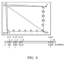
- FIG. 8 is a diagram for explaining the calibration for angle parameters of the camera.
- FIG. 9 is a diagram for explaining the calibration for distance parameters of the touch object.
- FIG. 10 is a diagram for explaining the calculation for obtaining a touch position.
- FIG. 3 is a configuration diagram showing an optical touch system in accordance with an embodiment of the invention.
- the optical touch system of the embodiment comprises a camera 301 , an active light source 302 and a processor 303 .
- the camera 301 is disposed at a corner of a touch area 304 , such that the field of view of the camera 301 can cover the entire touch area 304 .
- the active light source 302 is fixed on the camera 301 to lighten the touch object located on the touch area 304 .
- the touch object reflects the light beam omitted from the active light source 302 to the camera 301 .
- the processor 303 is used for calculating the position of the touch point 305 of the touch object.
- the distance between the touch point 305 and the camera 301 (for simplicity, a distance or a distance of the touch object is called in the following description) is D
- the angle between a line passing through the touch point 305 and the camera 301 and an edge of the touch area 304 (for simplicity, an angle or an angle of the touch object is called in the following description) is ⁇ .
- a specific position of the touch point 305 on the touch area 304 is determined.
- the methods for acquiring the distance D and the angle ⁇ are described in order in the following.
- FIG. 4 is a diagram for explaining the distance-acquisition method of the optical touch system shown in FIG. 3 .
- the camera 301 comprises a lens 306 and an image sensor 307 .
- the arrangement of the lens 306 and the image sensor 307 determines the field of view FOV of the camera 301 .
- a touch object O 1 forms an image I 1 on the image sensor 307 via the lens 306
- a touch object O 2 forms an image I 2 on the image sensor 307 via the lens 306 .
- there are two ways to acquire the distance of a touch object determining the distance according to the size of the image and determining the distance according to the brightness of the image.
- the touch object O 1 which is far from the lens 306 forms the small image I 1 on the image sensor 307 and the touch object O 2 which is close to the lens 306 forms the large image I 2 on the image sensor 307 . Therefore, the distance between a touch object and the camera 301 can be determined by the number of pixels possessed by the image on the image sensor 307 (Namely, the width of the image).
- FIG. 5 is a diagram for explaining a distance-acquisition method in accordance with an embodiment of the invention.
- an image with a width W 1 is formed on the image sensor 307 when the distance between a touch object and the camera 301 is D 1 and an image with a width W 2 is formed on the image sensor 307 when the distance between the touch object and the camera 301 is D 2 .
- Equation (1) as long as a given distance of the touch object and the corresponding width of the image (the number of pixels possessed by the image) are stored in the processor 303 in advance, any distance of the touch object can be acquired from the width of its image.
- the touch object O 1 which is far from the lens 306 forms the darker image I 1 on the image sensor 307 (because the amount of reflected right is less) and the touch object O 2 which is close to the lens 306 forms the brighter image I 2 on the image sensor 307 (because the amount of reflected right is greater). Therefore, the distance between a touch object and the camera 301 can be determined by the gray level of the image on the image sensor 307 (Namely, the brightness of the image).
- Equation (2) as long as a given distance of the touch object and the corresponding brightness of the image (the gray level of the image) are stored in the processor 303 in advance, any distance of the touch object can be acquired from the brightness of its image.
- the camera 301 comprises a lens 306 and an image sensor 307 . Therefore, a touch object located at a position with a specific angle ⁇ forms an image at a corresponding pixel position on the image sensor 307 .
- This characteristic can be utilized such that the angle ⁇ of the touch object is derived from the pixel position, on the image sensor 307 , of the image of the touch object.
- FIG. 6 is a diagram for explaining the angle-acquisition method of the optical touch system shown in FIG. 3 .
- the field of view of the camera 301 is 90° which exactly covers the entire touch area 304 and the image sensor 307 has 900 pixels (pixel number 0 ⁇ 899).
- the pixel position of the image shifts one pixel as the angle ⁇ of the touch object is varied by 0.1°. As shown in FIG.
- the pixel position of the image is used to derive the angle ⁇ of the touch object.
- the field of view of the camera is not limited to 90° and the total number of pixels is not limited to 900.
- FIG. 6 is just an example for easy understanding.
- FIG. 7 is a flowchart for explaining the touch-position detection operation of the optical touch system.
- FIG. 8 is a diagram for explaining the calibration for angle parameters of the camera.
- FIG. 9 is a diagram for explaining the calibration for distance parameters of the touch object.
- FIG. 10 is a diagram for explaining the calculation for a touch position.
- step S 1 calibrating the angle parameters of the camera.
- the edge of the touch area far from the camera is divided into numerous calibration reference points, and the center pixel position on the image sensor corresponding to each calibration reference point is recorded.
- calibration reference points 1 ⁇ N having their own predetermined angles ⁇ (Namely, the angle between the upper edge of the touch area and a line passing through a calibration reference point and the camera) are located along the right edge and the lower edge of the touch area. Then, a touch object is used to touch at least one calibration reference point and the center pixel position of the image corresponding to the calibration reference point touched by the touch object is recorded.
- the center position of the image of the touch object located at the calibration reference point 1 is located at the 12.5 th pixel position; the center position of the image of the touch object located at the calibration reference point 2 is located at the 100 th pixel position; the center position of the image of the touch object located at the calibration reference point 3 is located at the 160 th pixel position; the center position of the image of the touch object located at the calibration reference point N is located at the 626 th pixel position.
- an angle-to-image-position curve is obtained according to the angle of each calibration reference point and the pixel position of the corresponding image.
- step S 2 calibrating the distance parameters of the camera. Some positions on the touch area with different distances to the camera are set as calibration reference points, and the size or brightness of the image corresponding to each calibration reference point is recorded.
- two positions on the touch area with different distances to the camera are set as calibration reference points (a calibration reference point having a distance D 1 to the camera and a calibration reference point having a distance D 2 to the camera). Then a touch object is used to touch at least one calibration reference point and the size (W 1 and W 2 ) or brightness (L 1 and L 2 ) of the image corresponding to the calibration reference point touched by the touch object is recorded.
- the brightness of the image of the touch object located at the calibration reference point which is 30 mm away from the camera is the 1000 th gray level
- the brightness of the image of the touch object located at the calibration reference point which is 70 mm away from the camera is the 183.67 th gray level
- the brightness of the image of the touch object located at the calibration reference point which is 100 mm away from the camera is the 90 th gray level.
- the size of the image of the touch object located at the calibration reference point which is 30 mm away from the camera is 630 pixels; the size of the image of the touch object located at the calibration reference point which is 70 mm away from the camera is 270 pixels; and the size of the image of the touch object located at the calibration reference point which is 100 mm away from the camera is 189 pixels.
- a distance-to-image-brightness curve is obtained according to the distance of each calibration reference point and the corresponding image brightness, or a distance-to-image-size curve is obtained according to the distance of each calibration reference point and the corresponding image size.
- step S 3 calculating the touch position.
- the user performs a normal touch operation.
- the optical touch system determines the angle of the touch object according to the pixel position of the image of the touch object and the distance of the touch object according to the brightness or size of the image of the touch object. After a touch position is calculated, step S 3 is repeated if the user continues the touch operation.
- the touch object touches the touch area and forms an image on the image sensor, wherein the center position of the image is at the 300 th pixel and the width of the image is 270 pixels (spanning from the 165 th pixel to the 435 th pixel). Therefore, according to the angle-to-image-position curve it can be known that the touch point is located in the direction of angle 40°, and according to the distance-to-image-size curve it can be known that the touch point is located 70 mm from the camera.
- the processor determines a touch position of the touch point from the angle value and the distance value.
- the optical touch system and the optical touch-position detection method are described above.
- different touch objects have different characteristics such as different thicknesses.
- the touch object can touch at least one specified reference point on the touch area in advance for angle and distance calibration. In this way, the calculation for touch position becomes more accurate during normal touch operations.
- the optical touch system and the optical touch-position detection method of the invention only one camera detects touch positions, and an active light source fixed on the camera lightens a touch object such that the camera receives the light beam reflected from the touch object to capture an image. Therefore, the components of the conventional optical touch system such as a linear light source, a mirror, and a retro-reflector can be removed. In comparison to the prior art, the manufacturing cost on an optical touch system is reduced.
- the active light can be an infrared light-emitting diode or an infrared light laser diode.
- the image sensor must be capable of detecting infrared light images.
- a camera provided with a lens is described in the embodiment, but the lens can be replaced by a lens group consisting of a plurality of lenses.
Abstract
Description
W1/W2=D2/D1,
L1/L2=(D2/D1)2,
W1/W2=D2/D1 (1)
L1/L2=(D2/D1)2 (2)
Claims (12)
W1/W2=D2/D1,
W1/W2=D2/D1,
L1/L2=(D2/D1)2,
L1/L2=(D2/D1)2,
Applications Claiming Priority (3)
| Application Number | Priority Date | Filing Date | Title |
|---|---|---|---|
| TW101109281A TWI460637B (en) | 2012-03-19 | 2012-03-19 | Optical touch system and optical detecting method for touch position |
| TW101109281 | 2012-03-19 | ||
| TW101109281A | 2012-03-19 |
Publications (2)
| Publication Number | Publication Date |
|---|---|
| US20130241883A1 US20130241883A1 (en) | 2013-09-19 |
| US8982101B2 true US8982101B2 (en) | 2015-03-17 |
Family
ID=49157156
Family Applications (1)
| Application Number | Title | Priority Date | Filing Date |
|---|---|---|---|
| US13/764,270 Active 2033-09-21 US8982101B2 (en) | 2012-03-19 | 2013-02-11 | Optical touch system and optical touch-position detection method |
Country Status (3)
| Country | Link |
|---|---|
| US (1) | US8982101B2 (en) |
| CN (1) | CN103324356B (en) |
| TW (1) | TWI460637B (en) |
Cited By (3)
| Publication number | Priority date | Publication date | Assignee | Title |
|---|---|---|---|---|
| US20130278940A1 (en) * | 2012-04-24 | 2013-10-24 | Wistron Corporation | Optical touch control system and captured signal adjusting method thereof |
| US20160378266A1 (en) * | 2015-06-25 | 2016-12-29 | Wistron Corporation | Optical touch apparatus and width detecting method thereof |
| US10348983B2 (en) * | 2014-09-02 | 2019-07-09 | Nintendo Co., Ltd. | Non-transitory storage medium encoded with computer readable image processing program, information processing system, information processing apparatus, and image processing method for determining a position of a subject in an obtained infrared image |
Families Citing this family (5)
| Publication number | Priority date | Publication date | Assignee | Title |
|---|---|---|---|---|
| TWI525507B (en) * | 2013-10-22 | 2016-03-11 | 緯創資通股份有限公司 | Optical touch system, method of touch detection, and computer program product |
| TWI534687B (en) | 2014-01-24 | 2016-05-21 | 原相科技股份有限公司 | Optical touch detection system and object analyzation method thereof |
| LU92408B1 (en) * | 2014-03-21 | 2015-09-22 | Olivier Raulot | User gesture recognition |
| TWI612445B (en) * | 2015-09-21 | 2018-01-21 | 緯創資通股份有限公司 | Optical touch apparatus and a method for determining a touch position |
| TWI574196B (en) * | 2016-01-21 | 2017-03-11 | 緯創資通股份有限公司 | Optical touch apparatus, a method for determining a position of a touch indicator point and an optical touch system |
Citations (4)
| Publication number | Priority date | Publication date | Assignee | Title |
|---|---|---|---|---|
| US20080062149A1 (en) | 2003-05-19 | 2008-03-13 | Baruch Itzhak | Optical coordinate input device comprising few elements |
| US20080111797A1 (en) * | 2006-11-15 | 2008-05-15 | Yu-Sheop Lee | Touch screen |
| US20090185228A1 (en) * | 2004-08-21 | 2009-07-23 | Xerox Corporation | Real-time processing of grayscale image data |
| US20120092242A1 (en) * | 2009-03-27 | 2012-04-19 | Koninklijke Philips Electronics N.V. | Device for placement in front of a display device |
Family Cites Families (6)
| Publication number | Priority date | Publication date | Assignee | Title |
|---|---|---|---|---|
| JP4033582B2 (en) * | 1998-06-09 | 2008-01-16 | 株式会社リコー | Coordinate input / detection device and electronic blackboard system |
| JP4083941B2 (en) * | 1999-09-03 | 2008-04-30 | 株式会社リコー | Coordinate input device |
| TWM359744U (en) * | 2008-06-02 | 2009-06-21 | Tron Intelligence Inc | Sensing coordinate input device |
| JP2011210007A (en) * | 2010-03-30 | 2011-10-20 | Touch Panel Kenkyusho:Kk | Optical position detector |
| KR101706778B1 (en) * | 2010-07-19 | 2017-02-27 | 엘지이노텍 주식회사 | Optical touch screen |
| TWI421753B (en) * | 2010-08-12 | 2014-01-01 | Lite On Semiconductor Corp | Calibration method, detection device and optical touch panel for optical touch panel |
-
2012
- 2012-03-19 TW TW101109281A patent/TWI460637B/en active
- 2012-04-10 CN CN201210103737.7A patent/CN103324356B/en active Active
-
2013
- 2013-02-11 US US13/764,270 patent/US8982101B2/en active Active
Patent Citations (4)
| Publication number | Priority date | Publication date | Assignee | Title |
|---|---|---|---|---|
| US20080062149A1 (en) | 2003-05-19 | 2008-03-13 | Baruch Itzhak | Optical coordinate input device comprising few elements |
| US20090185228A1 (en) * | 2004-08-21 | 2009-07-23 | Xerox Corporation | Real-time processing of grayscale image data |
| US20080111797A1 (en) * | 2006-11-15 | 2008-05-15 | Yu-Sheop Lee | Touch screen |
| US20120092242A1 (en) * | 2009-03-27 | 2012-04-19 | Koninklijke Philips Electronics N.V. | Device for placement in front of a display device |
Non-Patent Citations (1)
| Title |
|---|
| Taiwanese language office action dated Jun. 24, 2014. |
Cited By (4)
| Publication number | Priority date | Publication date | Assignee | Title |
|---|---|---|---|---|
| US20130278940A1 (en) * | 2012-04-24 | 2013-10-24 | Wistron Corporation | Optical touch control system and captured signal adjusting method thereof |
| US10348983B2 (en) * | 2014-09-02 | 2019-07-09 | Nintendo Co., Ltd. | Non-transitory storage medium encoded with computer readable image processing program, information processing system, information processing apparatus, and image processing method for determining a position of a subject in an obtained infrared image |
| US20160378266A1 (en) * | 2015-06-25 | 2016-12-29 | Wistron Corporation | Optical touch apparatus and width detecting method thereof |
| US10719174B2 (en) * | 2015-06-25 | 2020-07-21 | Wistron Corporation | Optical touch apparatus and width detecting method thereof |
Also Published As
| Publication number | Publication date |
|---|---|
| CN103324356B (en) | 2016-06-01 |
| TWI460637B (en) | 2014-11-11 |
| TW201339920A (en) | 2013-10-01 |
| US20130241883A1 (en) | 2013-09-19 |
| CN103324356A (en) | 2013-09-25 |
Similar Documents
| Publication | Publication Date | Title |
|---|---|---|
| US8982101B2 (en) | Optical touch system and optical touch-position detection method | |
| KR101033428B1 (en) | Position detection apparatus using area image sensor | |
| TWI655448B (en) | Information processing device and information processing method | |
| US8937612B2 (en) | Coordinate locating method, coordinate locating device, and display apparatus comprising the coordinate locating device | |
| CN108475145B (en) | Image recognition device, image recognition method, and image recognition unit | |
| KR20160073866A (en) | An iris recognition device, an iris recognition system including the same and a method of operating the iris recognition system | |
| US20110115904A1 (en) | Object-detecting system | |
| WO2013035553A1 (en) | User interface display device | |
| US8629856B2 (en) | Apparatus and method for acquiring object image of a pointer | |
| KR20130040026A (en) | Method and apparatus for measuring distance of object | |
| US20140306934A1 (en) | Optical touch panel system, optical apparatus and positioning method thereof | |
| US20130241882A1 (en) | Optical touch system and optical touch position detecting method | |
| WO2018092627A1 (en) | Projector system | |
| JP6368593B2 (en) | Image processing program, information processing system, and image processing method | |
| KR101818104B1 (en) | Camera and camera calibration method | |
| US20230009071A1 (en) | Control method for light sources of vision machine, and vision machine | |
| TWI518575B (en) | Optical touch module | |
| JP4229964B2 (en) | Position detection device using area image sensor | |
| JP3898706B2 (en) | Position detection device using area image sensor | |
| US10782828B2 (en) | Optical touch apparatus and optical touch method | |
| US9727172B2 (en) | Method for defining effective pixels in image sensing array | |
| US10467769B2 (en) | Thin plate imaging device | |
| US9116577B2 (en) | Sensing method of optical touch |
Legal Events
| Date | Code | Title | Description |
|---|---|---|---|
| AS | Assignment |
Owner name: QUANTA COMPUTER INC., TAIWAN Free format text: ASSIGNMENT OF ASSIGNORS INTEREST;ASSIGNORS:LEUNG, CHEE-CHUN;LIU, YUN-CHENG;LIN, CHIEN-HUNG;REEL/FRAME:029790/0836 Effective date: 20130202 |
|
| STCF | Information on status: patent grant |
Free format text: PATENTED CASE |
|
| MAFP | Maintenance fee payment |
Free format text: PAYMENT OF MAINTENANCE FEE, 4TH YEAR, LARGE ENTITY (ORIGINAL EVENT CODE: M1551) Year of fee payment: 4 |
|
| MAFP | Maintenance fee payment |
Free format text: PAYMENT OF MAINTENANCE FEE, 8TH YEAR, LARGE ENTITY (ORIGINAL EVENT CODE: M1552); ENTITY STATUS OF PATENT OWNER: LARGE ENTITY Year of fee payment: 8 |