US8992529B2 - Implant plate, method and facility for the manufacture thereof - Google Patents
Implant plate, method and facility for the manufacture thereof Download PDFInfo
- Publication number
- US8992529B2 US8992529B2 US10/635,919 US63591903A US8992529B2 US 8992529 B2 US8992529 B2 US 8992529B2 US 63591903 A US63591903 A US 63591903A US 8992529 B2 US8992529 B2 US 8992529B2
- Authority
- US
- United States
- Prior art keywords
- head
- end portion
- implant
- implant plate
- edge
- Prior art date
- Legal status (The legal status is an assumption and is not a legal conclusion. Google has not performed a legal analysis and makes no representation as to the accuracy of the status listed.)
- Expired - Lifetime, expires
Links
- 239000007943 implant Substances 0.000 title claims abstract description 162
- 238000000034 method Methods 0.000 title abstract description 23
- 238000004519 manufacturing process Methods 0.000 title abstract description 17
- 239000000463 material Substances 0.000 claims abstract description 51
- 210000000988 bone and bone Anatomy 0.000 claims abstract description 49
- 238000004080 punching Methods 0.000 claims description 14
- 238000005096 rolling process Methods 0.000 claims description 12
- 230000000087 stabilizing effect Effects 0.000 claims description 11
- 238000005520 cutting process Methods 0.000 claims description 8
- 238000013532 laser treatment Methods 0.000 claims description 8
- 238000005452 bending Methods 0.000 claims description 4
- 238000005553 drilling Methods 0.000 claims description 4
- 229910000831 Steel Inorganic materials 0.000 claims description 3
- 229910001069 Ti alloy Inorganic materials 0.000 claims description 3
- RTAQQCXQSZGOHL-UHFFFAOYSA-N Titanium Chemical compound [Ti] RTAQQCXQSZGOHL-UHFFFAOYSA-N 0.000 claims description 3
- 239000010959 steel Substances 0.000 claims description 3
- 229910052719 titanium Inorganic materials 0.000 claims description 3
- 239000010936 titanium Substances 0.000 claims description 3
- 238000005516 engineering process Methods 0.000 abstract description 12
- 238000001356 surgical procedure Methods 0.000 abstract description 4
- 230000000399 orthopedic effect Effects 0.000 abstract description 3
- 206010017076 Fracture Diseases 0.000 description 29
- 208000010392 Bone Fractures Diseases 0.000 description 28
- 210000002758 humerus Anatomy 0.000 description 10
- 210000001519 tissue Anatomy 0.000 description 9
- 239000003356 suture material Substances 0.000 description 7
- 238000012986 modification Methods 0.000 description 6
- 230000004048 modification Effects 0.000 description 6
- 230000006641 stabilisation Effects 0.000 description 6
- 238000011105 stabilization Methods 0.000 description 6
- 239000011248 coating agent Substances 0.000 description 5
- 238000000576 coating method Methods 0.000 description 5
- 238000010622 cold drawing Methods 0.000 description 4
- 239000000126 substance Substances 0.000 description 4
- 238000003466 welding Methods 0.000 description 4
- 238000006243 chemical reaction Methods 0.000 description 3
- 238000005229 chemical vapour deposition Methods 0.000 description 3
- 238000004140 cleaning Methods 0.000 description 3
- 238000010276 construction Methods 0.000 description 3
- 238000013461 design Methods 0.000 description 3
- 238000003754 machining Methods 0.000 description 3
- 208000027418 Wounds and injury Diseases 0.000 description 2
- 238000005422 blasting Methods 0.000 description 2
- 238000012856 packing Methods 0.000 description 2
- 238000000926 separation method Methods 0.000 description 2
- 238000007493 shaping process Methods 0.000 description 2
- 238000005476 soldering Methods 0.000 description 2
- 239000007858 starting material Substances 0.000 description 2
- 206010020462 Humerus fracture Diseases 0.000 description 1
- 208000006735 Periostitis Diseases 0.000 description 1
- 239000008280 blood Substances 0.000 description 1
- 210000004369 blood Anatomy 0.000 description 1
- 238000005097 cold rolling Methods 0.000 description 1
- 238000006073 displacement reaction Methods 0.000 description 1
- 238000009826 distribution Methods 0.000 description 1
- 230000003628 erosive effect Effects 0.000 description 1
- 238000005242 forging Methods 0.000 description 1
- 230000035876 healing Effects 0.000 description 1
- 238000005098 hot rolling Methods 0.000 description 1
- 238000003780 insertion Methods 0.000 description 1
- 230000037431 insertion Effects 0.000 description 1
- 238000005259 measurement Methods 0.000 description 1
- 239000004081 narcotic agent Substances 0.000 description 1
- 210000003460 periosteum Anatomy 0.000 description 1
- 238000002360 preparation method Methods 0.000 description 1
- 238000003825 pressing Methods 0.000 description 1
- 238000011112 process operation Methods 0.000 description 1
- 238000012545 processing Methods 0.000 description 1
- 238000005482 strain hardening Methods 0.000 description 1
- 238000011282 treatment Methods 0.000 description 1
- 210000001364 upper extremity Anatomy 0.000 description 1
Images


Classifications
-
- A—HUMAN NECESSITIES
- A61—MEDICAL OR VETERINARY SCIENCE; HYGIENE
- A61B—DIAGNOSIS; SURGERY; IDENTIFICATION
- A61B17/00—Surgical instruments, devices or methods, e.g. tourniquets
- A61B17/56—Surgical instruments or methods for treatment of bones or joints; Devices specially adapted therefor
- A61B17/58—Surgical instruments or methods for treatment of bones or joints; Devices specially adapted therefor for osteosynthesis, e.g. bone plates, screws, setting implements or the like
- A61B17/68—Internal fixation devices, including fasteners and spinal fixators, even if a part thereof projects from the skin
- A61B17/80—Cortical plates, i.e. bone plates; Instruments for holding or positioning cortical plates, or for compressing bones attached to cortical plates
- A61B17/8061—Cortical plates, i.e. bone plates; Instruments for holding or positioning cortical plates, or for compressing bones attached to cortical plates specially adapted for particular bones
-
- A—HUMAN NECESSITIES
- A61—MEDICAL OR VETERINARY SCIENCE; HYGIENE
- A61B—DIAGNOSIS; SURGERY; IDENTIFICATION
- A61B17/00—Surgical instruments, devices or methods, e.g. tourniquets
- A61B17/56—Surgical instruments or methods for treatment of bones or joints; Devices specially adapted therefor
- A61B17/58—Surgical instruments or methods for treatment of bones or joints; Devices specially adapted therefor for osteosynthesis, e.g. bone plates, screws, setting implements or the like
- A61B17/68—Internal fixation devices, including fasteners and spinal fixators, even if a part thereof projects from the skin
- A61B17/82—Internal fixation devices, including fasteners and spinal fixators, even if a part thereof projects from the skin for bone cerclage
-
- A—HUMAN NECESSITIES
- A61—MEDICAL OR VETERINARY SCIENCE; HYGIENE
- A61B—DIAGNOSIS; SURGERY; IDENTIFICATION
- A61B17/00—Surgical instruments, devices or methods, e.g. tourniquets
- A61B17/56—Surgical instruments or methods for treatment of bones or joints; Devices specially adapted therefor
- A61B17/58—Surgical instruments or methods for treatment of bones or joints; Devices specially adapted therefor for osteosynthesis, e.g. bone plates, screws, setting implements or the like
- A61B17/68—Internal fixation devices, including fasteners and spinal fixators, even if a part thereof projects from the skin
- A61B17/80—Cortical plates, i.e. bone plates; Instruments for holding or positioning cortical plates, or for compressing bones attached to cortical plates
- A61B17/8085—Cortical plates, i.e. bone plates; Instruments for holding or positioning cortical plates, or for compressing bones attached to cortical plates with pliable or malleable elements or having a mesh-like structure, e.g. small strips
-
- A—HUMAN NECESSITIES
- A61—MEDICAL OR VETERINARY SCIENCE; HYGIENE
- A61B—DIAGNOSIS; SURGERY; IDENTIFICATION
- A61B17/00—Surgical instruments, devices or methods, e.g. tourniquets
- A61B17/56—Surgical instruments or methods for treatment of bones or joints; Devices specially adapted therefor
- A61B17/58—Surgical instruments or methods for treatment of bones or joints; Devices specially adapted therefor for osteosynthesis, e.g. bone plates, screws, setting implements or the like
- A61B17/68—Internal fixation devices, including fasteners and spinal fixators, even if a part thereof projects from the skin
- A61B17/84—Fasteners therefor or fasteners being internal fixation devices
- A61B17/842—Flexible wires, bands or straps
Definitions
- the invention relates to an implant plate, and a method for semi-automatic or fully automatic manufacture of implant plates for use thereof in surgery and/or orthopedics.
- the invention therefore relates to an at least one-part, internal humerus plate.
- the invention comprises a method for semi-automatic or fully automatic manufacture of implant plates for use as a product directly manufactured by process technology and plant engineering, in surgery and/or orthopedics.
- a substantially improved stabilization of a fracture of a head of an upper arm, and/or a fracture of a proximal upper arm is attained.
- shoe-horn shaped implant plates are formed to be wider in the region near the head of the upper arm, and narrower in the shaft region of the humerus.
- the region near the head of the implant plate has at least four drill holes, and the shaft region at least three drill holes. Furthermore, the region near the head of the implant plate has at least six drill holes close to the edge for accommodating metallic wire material, or resorbable and non-resorbable thread material, for holding together the fracture parts of the head. From DE 197 50 493 A1 an implant is known for use in surgery for stabilizing a humerus-head fracture by means of a screw.
- this implant is repeatedly also described as being a plate, the constructional configuration is substantially based on that of a massive square bar, the shaft region of which has a reduced material thickness, and the head-near region of which has, by comparison, a substantially doubled material thickness.
- the head-near region of the square bar is shaped to be substantially concave towards the humerus head.
- the fabrication of the basic spatial shape of the implant requires costly measures of processing by forging, pressing, and/or cutting operations.
- this implant has two guides for bone screws, with which these screws are stably held at an angle to the plate for setting the fracture.
- the screws are releasably fixed by means of a clamping device to prevent a rotation of the screw shaft, and a displacement along the direction of the screw shaft.
- a clamping device to prevent a rotation of the screw shaft, and a displacement along the direction of the screw shaft.
- a special screw having a thread outer diameter that is greater than the diameter of the adjoining shaft.
- the shaft diameter is enlarged in the region of the screw head.
- the implant has drill holes for shaft screws, which are substantially directed perpendicularly to the longitudinal axis of the rod-shaped implant.
- drill boles are provided to extend parallel to the upper and the lower side of the rod-shaped implant, serving to accommodate purse-string wire-sutures, and resorbable or non-resorbable sutures for resetting torn-out tubercules.
- the specific shoe-horn shaped implant plate for stabilizing a fracture of an upper-arm head as known from the Prospectus “PHILOS-Proximal Humerus Internal Locked System” November 00/EMA/Docseries VI, of the firms of Stratec/Mathys, has in the head-end portion, drill holes close to the edge for accommodating wire cerclages or resorbable or non-resorbable suture material, but nevertheless, this construction makes it difficult to thread these fastening members, and to loop them around the plate edge, so that because of the short guiding length, this suture material may become damaged, and the wire cerclages may be jammed. In both cases, the fastening member may be ruptured.
- the fastening members first prevent a large plate area from bearing against the bone surface, and then render difficult a subsequent threading operation.
- the square-bar shaped implant known from DE 197 50 493 A1 has two drill holes distributed on its massive, head-end portion, that extend parallel to the upper and lower end of the implant, however, this embodiment cannot be simply converted to an implant plate.
- the two drill holes are made possible only because the massive, head-near portion of the implant is of a material that has been adequately reinforced in comparison with that of the shaft-near portion.
- this implant is not easily usable in surgical practice, because the massive proximal upper-arm head-screws cause an additional loss of bone owing to a necessary preliminary boring operation.
- a massive embodiment of this kind is, not necessary, because of the relatively small load acting on this upper extremity, and interferes with surrounding parts of soft body tissue.
- the invention is based on the problem of creating an implant plate giving a substantially improved stabilization of a fracture of an upper arm and/or a fracture of a proximal upper arm. Apart from this, a method for semi-automatic or fully automatic manufacture of the implant plates
- an implant plate for stabilizing a fracture of an upper-arm head or a fracture of a proximal upper arm, and formed to a flat longitudinal channel for bearing against a bone comprising: a head-end portion and a shaft-end portion, forming a spoon-shaped outer contour; holes for bone screws; and at least one raised receiving member for a flexible fastening member, such as a wire cerclage or a surgical suture material, disposed at an outer edge or contour of a side of the head-end portion of the implant plate facing away from the bone; wherein the at least one receiving member has an aperture extending substantially parallel to an outer edge or contour, and to the upper and lower side of the head-end portion of the implant plate, for threading, passing-through, and drawing together the flexible fastening member; and the at least one receiving member is provided with the aperture by being formed to be one of a tube, an eyelet, a round hook, and a ridge perpendicular to an outer edge of the head-end portion and
- an implant plate for stabilizing a fracture of an upper-arm head or a fracture of a proximal upper arm, and formed to a flat longitudinal channel for bearing against a bone, the implant plate having a head-end portion and a shaft-end portion, a spoon-shaped contour, and holes for bone screws; comprising the step of: fitting the head-end portion of the implant plate with at least one raised receiving member for a flexible fastening member, such as a wire cerclage or a surgical suture material, disposed at an outer edge or contour of a side of the head-end portion that faces away from the bone; and comprising the further step of: providing the at least one receiving member with an aperture extending substantially parallel to an outer edge or contour, and to the upper and lower side of the head-end portion facing away from the bone, for threading, passing through, and drawing together the flexible fastening member, by forming the receiving member to be one of a tube, an eyelet, a round hook, and a ridge perpen
- the principle of the solution on which the invention is based consists substantially of a spoon-shaped implant plate having drill holes and/or oblong holes for bone screws being provided for stabilizing a fracture of an upper-arm head or an upper arm, the plate having at least one raised receiving member for flexible fastening members, and the receiving member being provided on the side facing away from the bone and on the longitudinal axis at the upper edge of the spoon-shaped portion.
- at least one receiving member can be disposed at each longitudinal edge on the side of the implant plate facing the bone.
- Each receiving member has an aperture extending substantially parallel to the respective plate edge.
- the apertures are preferably designed to be eyelets, round hooks, or tubes, wherein slightly curved and relatively long guide paths substantially facilitate and improve an operation of threading, passing through, and drawing together the employed flexible fastening members which are wound around the fracture.
- the entry and exit edges of the apertures must be blunted, rounded and/or smoothed, in order that the flexible fastening members may not be damaged or destroyed.
- Each implant plate may have a blade disposed along the longitudinal axis, starting out from the upper edge of the spoon-shaped portion of the implant plate, the blade being driven into the humerus head in an angled state.
- the blade has at least one drill hole having at least one screw-thread into which an upper-arm head-screw is screwed to extend obliquely upwards from the head-end portion or head portion of the implant plate.
- the implant plate has at least one respective drill hole and/or oblong hole. The insertion of the upper-arm head-screws from the implant plate to the angled blade creates a stable angled connection, whereby the support of the blade on the humerus head and the implant plate at the upper-arm head and the proximal upper arm is improved.
- the receiving members disposed close to the edge on the side of the implant plate facing away from the bone decisively improve the operations of threading, guiding and drawing together the flexible fastening member with which the fracture of the upper-arm head and/or the proximal upper arm is additionally stabilized.
- This constructive design of the implant plate thus ensures the operations of inserting, threading, and passing-through, and also of tightening the flexible fastening members even after the plate has been secured to the bone.
- the principle of the solution in accordance with the invention also comprises a method according to which the implant plates are fabricated semi- or fully automatically, and also semi- or fully continuously, by programmed control from metallic flat-strip or strip material, consisting for example of implant steel, titanium or titanium alloys and the like.
- the flat strip which is kept available having the necessary measurements, either cut to length from a stacking magazine, or in the form of a coil may be first cold-worked in order to produce, for example, naps, discontinuous grooves, and the like on the surface of the side of the implant plate intended to bear against the bone, in order that sustenance of the periosteum and the bone be maintained during subsequent use of the inserted implant plate.
- the flat strip may also be kept available, suitably provided with a surface profile by means of preceding hot or cold rolling, as a starting material for the method of the invention. Thereupon the flat strip is worked by machining or the like according to a previously determined configuration in order to produce apertures such as drill-holes, openings, and the like, having a relatively large diameter for the bone screws, and apertures such as drill holes, openings, and the like, having a relatively small diameter, in the receiving members that are to be formed from the flat strip material, for flexible fastening members.
- forming-cuts such as parallel slits, oblique cuts, partial cuts and the like are made close to the edge of the flat strip, as needed for forming the receiving members, and possibly also the blade, for example by cutting, punching, laser treatment, machining, eroding and the like.
- the regions of the flat strip prepared for forming the receiving members close to the edge are cold-formed, i.e. deep drawn, bent, rolled, angled and the like, in the direction of the side facing away from the bone, so that the receiving members for the flexible fastening members on the side of the implant plate facing away from the bone are visibly raised, but only to a small height.
- the apertures such as drill holes, openings, and the like, previously formed in the receiving members, are then positioned close to the edge to be substantially parallel to the course of the plate edge, and also to the upper and lower side of the implant plate yet to be completed.
- Cold-forming may also be applied to forming spaced regions of weakened material extending across the longitudinal axis, for later use as strap hinges or positions of separation for producing interlocking hinges, and for sharpening the edges at the free end of the blade.
- the flat strip as prepared to this extent, may be cold-formed to a flat longitudinal channel substantially not including the blade region, in order to optimize a bearing of the implant plate, in later use, against the bone.
- the implant blanks having the spoon-shaped outer contour are produced from the bowed strip material by material removal, for example by punching, laser treatment, cutting, machining, and the like, and singled at the same time.
- a flat strip of a width greater than the width of the spoon-shaped portion of the implant plate is used in order to punch, cut by laser, cut, and the like, wide or narrow rectangular ridges from the excess plate-edge region.
- tubular or round-hook shaped receiving members of low height are formed for drawing-through flexible fastening members.
- a singling operation on the flat strip that has been prepared to this extent, to yield implant blanks, is also effected by suitable removal of material.
- the singled implant plate blanks are subsequently imparted with the predetermined flat channel profile by cold-working.
- externally prefabricated receiving members for the flexible fastening members having the shape of tubular sections, round hooks, eyelets and the like of a low projecting height and an opening cross-section matched to the diameters of the flexible fastening members, may be attached to the surface of the singled implant blanks close to the edges before or after the bowing, i.e. flat-channel shaping of the blanks by cold-forming, welding, press-welding, soldering, screwing, and the like.
- the implant plate blanks fitted with receiving members for flexible fastening members attain the final state of fabrication following deburring, rounding of edges, and cleaning.
- the implant plates may be surface-finished by galvanic, electro-chemical, or vacuum-technological methods such as the CVD method (Chemical Vapor Deposition).
- the implant plates are sterilized and supplied for surgical use suitably packed.
- a facility associated with the invention is of linear and modular construction, and comprises substantially program-controlled, semi or fully automatically operating and timed fabrication machines or automatic machines with which the flat strip is processed to form the receiving members for flexible fastening members, and with which the implant plate, possibly including the blade, is also made.
- the individual devices may be disposed for operative cooperation in a linear array, or opposite to each other, or in a meandering configuration, or also in a roundabout, turnstile, or double star arrangement.
- the implant plates, and also the implant plates directly produced by the method, possibly using the plant are utilized for stabilizing fractures of an upper arm head and a proximal arm.
- FIG. 1A shows a front view, with a drawn-in longitudinal sectional line A-A, of a spoon-shaped implant plate for additional stabilization of a fracture of an upper-arm head, and/or of a proximal upper arm, the implant plate having drilled holes and/or oblong holes for bone screws in a spoon- and shaft-end portion, and also ridge-shaped receiving members for flexible fastening members in a region close to the edge of the head-end portion or spoon portion of the implant plate.
- FIG. 1B shows a side view of the arrangement of FIG. 1A of an implant plate on an upper-arm head and on a proximal upper arm along a longitudinal section A-A.
- FIGS. 2A-2C show a magnified front and side view, and also a plan view, of the ridge-shaped receiving member of FIGS. 1A-1C , with a sectional line B-B through the side view.
- FIG. 3A shows a front view of a spoon-shaped implant plate with a widened head-end portion or spoon portion, and a narrower shaft-end portion or shaft portion, having distributed drill holes and/or oblong holes for bone screws and tubular-shaped receiving members for flexible fastening members in a region close to the edge of the head-end portion, and also a blade extending from the upper end of the head-end portion for additional stabilization of a fracture of an upper-arm head and a proximal upper arm.
- FIG. 3B shows a side view of the arrangement of FIG. 3A of the spoon-shaped implant plate on an upper-arm head and a proximal upper arm, with a driven-in blade, and also the tubular receiving members.
- FIGS. 4A-4C show a front and side view, and also a plan view of a tubular receiving member of FIGS. 3A and 3B in a region close to the edge of the head-end portion.
- FIG. 5 shows a front view of an implant plate based on FIGS. 1A and 3A , with modifiable locating positions, shown as circles, for receiving members in a region close to the edge of the head-end portion, for additional stabilization of a fracture of an upper-arm head and a proximal upper arm.
- FIGS. 6A-6C show a front and side view, and also a plan view of an eyelet-shaped receiving member, formed from a deep-drawn slit close to an edge, for a flexible fastening member, in a modification of the arrangement of FIG. 5 .
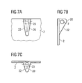
- FIGS. 7A-7C show a front and side view, and also a plan view of an eyelet-shaped receiving member, formed from a fold close to an edge, for a flexible fastening member, in a modification of the arrangement according to FIG. 5 .
- FIGS. 8A-8C show a front and side view, and also a plan view of an eyelet-shaped receiving member, formed from a deep-drawn cup close to an edge, for a flexible fastening member, in a modification of the arrangement according to FIG. 5 .
- FIGS. 9A-9C show a front and side view, and also a plan view of a receiving member, cut from excess plate material close to an edge in the form of a tab and bent to hook-shape, for a flexible fastening member, in a modification of the arrangement according to FIG. 5 .
- FIGS. 10A-10C show a front and a side view, and also a plan view of a receiving member, cut from excess plate material close to an edge in the form of a flange and bent, for a flexible fastening member, in a modification of the arrangement according to FIG. 5 .
- FIGS. 11A-11C show a front and a side view, and also a plan view of a triangular receiving member, cut obliquely from plate material close to an edge and bent at an angle, for a flexible fastening member, in a modification of the arrangement according to FIG. 5 .
- FIG. 12 shows the ridge-shaped receiving member for a flexible fastening member in a magnified view of the section B-B of the side view of FIG. 2B .
- FIG. 13 shows a front view of a three-part spoon-shaped implant plate having regions of weakened material or self-interlocking hinges extending across the longitudinal axis A-A between the blade, spoon and shaft portions.
- FIG. 14 shows a side view of a three-part implant plate having strap hinges between the blade and the head-end portion, and also between the head-end portion and the shaft-end portion.
- FIG. 15 shows a side view of a three-part implant plate having adjacent hinge-like interlocking portions between the blade and the head-end portion, and also between the head-end portion and the shaft-end portion.
- FIG. 16 shows a process operation and a linear modular configuration of a facility for manufacturing the implant plates according to the invention.
- the invention comprises the design of the structure of an implant plate for stabilizing a fracture of an upper-arm head and/or a fracture of a proximal upper arm, the implant plate having, in addition to drill holes for upper-arm head-screws and shaft screws, receiving members disposed close to the edge on the side of the head portion facing away from the bone, for flexible fastening members such as wire cerclages or surgical suture material.
- the implant plate has a substantially uniform thickness of material of about 0.5 to 6.5 mm, preferably of 0.8 to 3.5 mm.
- the head-end portion of the implant plate is formed to be spoon-shaped.
- the shaft-end portion of the implant plate is formed to be narrower, having a flat stem-shape.
- the spoon-shaped implant plate is of slightly convex curvature, and a cross-section that is slightly bowed, or of hollow-ground shape, or formed as a shallow channel-profile.
- the head-end portion has at least one drill hole and/or oblong hole for upper-arm head-screws.
- the shaft-end portion has at least one drill hole and/or oblong hole for shaft screws.
- at least three receiving members, formed as ridges, for fastening members are provided close to the edge on the spoon-shaped portion of the implant plate to protrude from the side facing away from the bone. These eyelet-shaped receiving members facilitate rapid threading of the flexible fastening member, such as a wire cerclage or surgical suture material.
- FIGS. 1A and 1B show an implant plate 1 according to the invention, having a head-end portion 2 and a shaft-end portion 3 .
- the head-end portion 2 has two drill holes 5 , equally spaced from the longitudinal axis A-A of the implant plate, and two further drill holes 5 , located on the longitudinal axis A-A, for upper-arm screws.
- the shaft-end portion 3 has three drill holes 5 , equally spaced along the longitudinal axis A-A, for shaft screws.
- the head-end portion 2 has, on the surface of the implant plate 1 facing away from the bone 4 , six substantially uniformly distributed, ridge-shaped receiving members 6 having apertures 7 that are designed as drill holes 14 for not shown flexible fastening members.
- the apertures 7 must extend substantially parallel to the upper and lower side of the implant plate 1 , and also parallel to the outer edge or contour 8 of the head portion 2 , whereby threading and guiding of the flexible fastening members, and also looping of the flexible fastening members around, and drawing together the fracture is decisively improved.
- the implant plate 1 is designed to be of one piece, and of slight convex curvature, in order to bear well against the upper-arm head and the proximal upper arm.
- FIGS. 2A-2C show a magnified front and side view, and also a plan view, of the receiving member 6 of FIGS. 1A and 1B , formed as a ridge 10 .
- Each ridge 10 is aligned to be substantially perpendicular to an outer edge 6 of the head-end portion 2 of the implant plate 1 , and has a drill hole 14 representing the aperture 7 .
- Outer edges 9 of the drill hole 14 are rounded, so that the not shown flexible fastening member may be easily threaded and guided without being damaged.
- the edges 11 of the ridge 10 have also been blunted or rounded, to protect tissue.
- the ridge 10 is formed to be of semi-circular shape.
- the ridge 10 may be of semi-oval shape, square, or rectangular, the corners and edges 11 being blunted or rounded in each case, in order to protect tissue.
- the ridge 10 may be disposed on a plate-shaped, round, square, rectangular, triangular, or oval base 12 .
- the base 12 may be welded, pressure welded, soldered, or screwed onto the side of the implant plate 1 facing away from the bone 4 , at a position close to the edge.
- the base 12 may also be dispensed with, so that the ridge 10 may be suitably fixed directly onto the implant plate 1 , at a predetermined location close to the edge.
- FIGS. 3A and 3B illustrate a spoon-shaped implant plate 1 having a blade 13 that extends from the head-end portion 2 , and is disposed along an extension of the longitudinal axis A-A of the implant plate, and has a sharp edge at the end.
- two spaced drill holes 15 having at least one cut-in thread are provided within the portion of the blade 13 lying along this longitudinal axis of the implant plate 1 .
- the blade 13 can be suitably bent at an angle depending on the fracture of the upper-arm head, and driven into the upper-arm head.
- the head-end portion 2 of the implant plate 1 has two drill holes 5 equally spaced from the longitudinal axis A-A, and two drill holes 5 lying on the longitudinal axis A-A, for upper-arm head-screws.
- the shaft-end portion 3 has three drill holes 5 equally spaced from each other along the longitudinal axis, for shaft screws.
- the two drill holes 5 that are spaced from each other on the longitudinal axis A-A may also be designed to be oblong holes for the upper-arm head-screws.
- two upper-arm head-screws in particular the two upper-arm head-screws lying on the longitudinal axis A-A, may be directed towards the two drill holes 15 of the blade 13 and screwed into the at least one thread of the drill holes 15 .
- This embodiment makes possible a locking of the implant plate to prevent it from moving out of the humerus head, so that a stable angular connection between the bone 4 or humerus head, the blade 13 , and the implant plate 1 is created.
- FIGS. 4A-4C illustrate a magnified front and side view, and also a plan view, of a tubular-shaped receiving member 16 of FIGS. 3A and 3B .
- a tubular-shaped receiving member 16 is disposed on the blade-side edge region of the head-end portion 2 of the implant plate 1 across the longitudinal axis A-A and parallel to the upper side of the implant plate 1 .
- a tubular-shaped receiving member 16 is disposed at each of the opposite longitudinal edges 17 of the head-end portion 2 to be close to the edge and also substantially parallel to the longitudinal edge 17 and parallel to the upper side of the implant plate 1 .
- the edges of the exits 18 of the tubular receiving members 16 are rounded.
- the exits 18 of the tubular receiving members 16 are directed towards the associated outer edge or contour 8 of the implant plate 1 .
- FIG. 5 illustrates the head-end portion 2 of the implant plate 1 with the blade 13 , and the shaft-end portion 3 , both being shown only with broken lines.
- variable locating positions 19 indicated by means of circular broken lines, for further embodiments of receiving members 6 for flexible fastening members are provided.
- FIGS. 6A-6C illustrate a front- and side view, and also a plan view, of a receiving member 20 having an eyelet-shaped aperture 7 for flexible fastening members, as usable with the locating possibilities 19 of FIG. 5 .
- This receiving member, having an eyelet-shaped aperture 7 has been produced by deep drawing from a parallel slit 21 close to the edge of the implant plate 1 . All edges intended to contact the flexible fastening member and the tissue have been rounded.
- FIGS. 7A-7C illustrate a front and side view, and also a plan view, of a further receiving member 20 having an eyelet-shaped aperture 7 for flexible fastening members, as usable with the locating possibilities 19 of FIG. 5 .
- This eyelet-shaped aperture 7 of the receiving member 20 has been produced by deep drawing a region close to the edge of the implant plate 1 to a fold 22 , and by providing a through drill hole 23 . All edges intended to contact the flexible fastening member and the tissue have been rounded.
- FIGS. 8A-8C illustrate a front and side view, and also a plan view, of a further receiving member 20 having an eyelet-shaped aperture 7 for flexible fastening members, as usable with the locating possibilities 19 of FIG. 5 .
- This receiving member 20 with the eyelet-shaped aperture 7 has been produced by deep drawing a region close to the edge of the implant plate 1 to a cup 24 , and by providing a through drill hole 23 .
- FIGS. 9A-9C illustrate a front and side view, and also a plan view, of a round-hook shaped receiving member 25 for flexible fastening members 29 , as usable with the locating possibilities 19 of FIG. 5 .
- This round-hook shaped receiving member 25 has been produced by punching a narrow strip-shaped extension 26 from an excess edge region of the implant plate 1 , and subsequently edge-rolling the free end of the extension 26 to a round hook 25 . All edges intended to contact the flexible fastening member and the tissue have been rounded.
- FIGS. 10A-10C illustrate a front and side view, and also a plan view, of another tubular receiving member 16 for flexible fastening members, as usable with the locating possibilities 19 of FIG. 5 .
- This tubular receiving member 16 has been produced by punching a wide rectangular extension 26 from an excess edge region of the implant plate 1 , and subsequently edge-rolling the free end of the extension 26 to a tubular receiving member 16 . All edges intended to contact the flexible fastening member and the tissue have been rounded.
- FIGS. 11A-11C illustrate a front and side view, and also a plan view, of a triangle-shaped receiving member 27 provided with a drill hole 23 and formed by means of an oblique cut 28 close to the edge in the strip material, and subsequently bending-away material substantially vertically from the upper side of the implant plate 1 . All edges intended to contact the flexible fastening member and the tissue have been rounded.
- FIG. 12 shows a magnified view of the ridge 10 along the sectional line B-B of the side view of FIG. 2B .
- the aperture 7 i.e., the drill hole 14
- the drill hole 14 may be conformed to the diameter of the flexible fastening member 29 , but may also be larger in order to facilitate threading, and possibly multiple threading-through of the flexible fastening member 29 .
- FIG. 13 illustrates a front view of a three-part, spoon-shaped implant plate 1 having at least two regions 30 of weakened material extending across the longitudinal axis A-A between the head-, shaft-, and blade portions 2 , 3 , 13 .
- the two regions 30 of weakened material are used as strap hinges 31 or positions of separation for producing interlocking hinges 32 .
- FIG. 14 illustrates a side view of three regions 30 of weakened material of the implant plate 1 , which can be used during later surgical application as strap hinges 31 to improve fitting to the shape of the upper-arm head and proximal upper arm, because the desired angling of the head- and blade-portions may be achieved in this manner.
- FIG. 15 illustrates a side view of two regions 30 of weakened material of the implant plate 1 , which can be used during later surgical application as self-interlocking hinges 32 to improve fitting to the shape of the upper-arm head and proximal upper arm, because the desired angling of the head- and blade-portions may be achieved also with this embodiment.
- the implant plate 1 may be designed to consist of only two parts by omitting the blade 13 , wherein the region 30 of weakened material between the head-portion 2 and the shaft-portion 3 is utilized as a strap hinge 31 or a self-interlocking hinge 32 for angling and fitting to the bone 4 .
- the regions 30 of weakened material may be used in combination as a strap hinge 31 and a self-interlocking hinge 32 .
- FIG. 16 illustrates the method as applied in a facility for manufacturing the implant plates 1 .
- the method comprises a semi or fully automatic manufacture of implant plates 1 that are used for stabilizing a fracture of an upper-arm head and/or a fracture of a proximal upper arm.
- a metallic strip-material 42 that is compatible with the human body, and that is available cut to length and stapled in a magazine or store 40 , or as a coil 41 , and that consists, for example, of implant steel, titanium, or titanium alloys, is used as a starting material for the implant plate 1 .
- the strip material 42 is of a substantially uniform thickness of 0.5 to 6.5 mm.
- the strip width is governed by the respective maximum width of the head-end portion 2 of the spoon-shaped implant plate 1 .
- the width may also be greater for the purpose of forming receiving members 6 from the strip material 42 .
- the strip widths to be employed are determined by the use of the implant plates 1 for adults, young persons, or children.
- the strip material 42 that is available from the magazine 40 or from the uncoiling device 41 may be passed through a rolling mill 44 provided with a drilling machine 45 and/or a laser device 46 under computer control and timing.
- the surface of a roll of the rolling mill 44 may be profiled and may produce a nap profile, or discontinuous groove- or diamond-shaped profiles, and the like, on that side of the strip material 42 of the implant plate 1 being manufactured that will later face the bone.
- the drilling machine 45 and/or the laser device 46 produce the necessary drill holes 14 , 23 or holes that form the apertures 7 in the receiving members 6 for the flexible fastening members 29 .
- the strip material 42 is then processed in a punching device 47 that may be combined with the laser device 46 and/or a cutting device 48 .
- Parallel slits 21 , strip-shaped extensions 26 close to the edge, and the like, for example, are produced in these devices under program control.
- the strip material 42 is processed under computer control and timing in a deep-drawing device 49 that may be combined with a bending device 50 and/or edge-rolling device 51 , in order to form eyelets from parallel slits 21 or cups 24 , or to form folds 22 from plate regions close to the edge, or to bend oblique cuts 28 located close to the edge at an angle, or to coil-inwards strip-shaped extensions 26 of excess material.
- the spoon-shaped final configuration is then produced, and the singling of the strip material 42 to implant plate blanks 1 is performed in a separating device 52 , for which purpose use may be made of the laser device 46 , the punching device 47 , and/or the cutting device 48 .
- the strip material 42 may be cold-formed to a flat channel-profile in a cold-drawing device 65 before or after the singling operation in which implant plate blanks are produced.
- the rolling mill 44 with suitable conversion, by reversing the implant plate blanks 1 .
- the implant plates 1 are supplied to a deburring device 53 combined with a shot-blasting device 54 , rounding device 55 , and cleaning device 56 . Then the implant plates 1 may be surface-finished in a coating device 57 . The finishing of the implant plate 1 may be performed using galvanic, electro-chemical, or vacuum-technological coating techniques. Vacuum technological coating comprises chiefly CVD technology (chemical vapor deposition). Finally, the implant plates 1 are prepared for dispatch in a sterilizer 58 in association with packing devices 59 , and sent-out for distribution.
- the facility provided by the invention is of modular construction and comprises substantially the following devices, in particular, program-controlled, semi or fully automatically operated and timed manufacturing machines for performing the preparation of the metallic strip material 42 , and for forming the receiving members 6 for flexible fastening members 29 , and also the final configuration of the implant plates 1 , possibly fitted with blades 13 :
- a rolling mill 44 for at least one-sided surface profiling of the strip material 42 , e.g. for producing naps, discontinuous groove-shaped or diamond-shaped profiles, and the like, on the side facing the bone 4 ,
- a drilling, laser-treatment, and/or punching device 45 , 46 , 47 in particular, a suitable automatic machine for producing apertures 7 , positioned holes, or drill holes 23 , and the like;
- a laser-treatment, punching, and/or cutting device 46 , 47 , 48 in particular, a suitable automatic machine for preparing the strip material 42 for forming raised receiving members 6 on the side of the implant plate 1 facing away from the bone, and also, if required, a blade 13 extending from the spoon-shaped portion 2 of the implant plate blank 1 ;
- a suitable automatic machine for shaping the raised receiving members 6 on the side of the implant plate blank facing away from the bone 4 and also, if required, U, T, or I shaped profiles on the blade 13 by cold-forming;
- further laser-treatment, punching, and/or cutting devices 46 , 47 , 48 in particular, a suitable automatic machine for producing an outer contour 8 and singling implant plate blanks 1 ;
- the individual devices are disposed in a linear array.
- the devices of the plant may also be disposed in rows opposite to each other, or displaced with respect to each other in a meandering configuration.
- the plant may be built-up in a roundabout, turnstile, or double-star arrangement, wherein the individual devices operationally cooperate. Automatic machines having multiple functions may be applied repeatedly, making use of process and plant technology, if necessary after any needed operational conversion, so that the technical outlay of plant and devices for performing the individual method steps may be reduced by reversing the strip material 42 or the implant plate blanks 1 .
- the individual portions 30 of weakened material of the implant plate 1 may be utilized as strap hinges 31 .
- the fabrication by means of process and plant technology is effected preferably in a separate cold-drawing device 65 .
- the rolling mill 44 too may be used for cold-drawing the strip material 42 by suitable conversion, in order to produce regions 30 of weakened material in the strip material 42 under program control.
- the manufacture of the two- or three-part implant plates 1 is performed in such manner that the strip material 42 is separated into the blade-, head- and/or shaft-end portions 2 , 3 , 13 by punching or laser-treatment.
- the adjacent edges of the singled portions 2 , 3 , 13 are formed to be self-interlocking hinges, and are connected together to be movable within limits by being fitted into each other.
- the implant plates 1 of the invention are used for stabilizing fractures of an upper-arm head and/or a proximal upper arm, wherein a setting of a fracture is effected by means of the implant plate 1 , the head and shaft screws, and also the flexible fastening members 29 that are wound around the fractured parts, in particular the tubercle, and are used together with the receiving members 6 disposed close to the edge on the upper side of the implant plate 1 .
- the apertures 7 of the receiving members 6 extend substantially parallel to the outer contour 8 of the head portion 2 .
Abstract
An implant plate according to the invention, for use in surgery or orthopedics, serves to stabilize a fracture of an upper-arm head or a fracture of a proximal upper arm. A head portion of the implant plate is fitted with at least one raised receiving member for a flexible fastening member on a side facing away from a bone. Each receiving member has an aperture extending substantially parallel to an outer edge or contour, and to an upper and lower side of the implant plate for threading, passing-through, and drawing together the flexible fastening member. The receiving member can be formed using process and plant technology from strip material, or using externally fabricated receiving members that are welded, press-welded, soldered, screwed, or riveted onto an outer side of the implant plate. The invention also comprises a method for manufacturing the implant plates.
Description
This is a continuation of International Patent Application No. PCT/DE2002/000025, filed Feb. 8, 2002, which claims priority to German Patent Application No. 10107369.0, filed Feb. 16, 2001.
1. Field of the Invention
The invention relates to an implant plate, and a method for semi-automatic or fully automatic manufacture of implant plates for use thereof in surgery and/or orthopedics.
The invention therefore relates to an at least one-part, internal humerus plate. In addition, the invention comprises a method for semi-automatic or fully automatic manufacture of implant plates for use as a product directly manufactured by process technology and plant engineering, in surgery and/or orthopedics. With the implant plate according to the invention, a substantially improved stabilization of a fracture of a head of an upper arm, and/or a fracture of a proximal upper arm is attained.
2. Description of the Related Art
General prior art includes metallic implant plates having a substantially constant thickness or strength along a longitudinal and lateral cross-section. With these plates, bone fractures are fixed in position and held together with bone screws during processes of healing. From the Prospectus “PHILOS-Proximal Humerus Internal Locked System”, November 00/EMA/Docseries VI, of the firms of Stratec/Mathys, a specific shoe-horn shaped implant plate for stabilizing a proximal humerus fracture is known. Drill holes are provided along the middle plate section for bone screws which are directed, on the one hand, into the upper-arm head with the spongy tubercle and, on the other hand, into the proximal shaft region of the humerus. These shoe-horn shaped implant plates are formed to be wider in the region near the head of the upper arm, and narrower in the shaft region of the humerus. The region near the head of the implant plate has at least four drill holes, and the shaft region at least three drill holes. Furthermore, the region near the head of the implant plate has at least six drill holes close to the edge for accommodating metallic wire material, or resorbable and non-resorbable thread material, for holding together the fracture parts of the head. From DE 197 50 493 A1 an implant is known for use in surgery for stabilizing a humerus-head fracture by means of a screw. Although in DE 197 50 493 A1 this implant is repeatedly also described as being a plate, the constructional configuration is substantially based on that of a massive square bar, the shaft region of which has a reduced material thickness, and the head-near region of which has, by comparison, a substantially doubled material thickness. The head-near region of the square bar is shaped to be substantially concave towards the humerus head. The fabrication of the basic spatial shape of the implant requires costly measures of processing by forging, pressing, and/or cutting operations. In the head-near region, this implant has two guides for bone screws, with which these screws are stably held at an angle to the plate for setting the fracture. Preferably, the screws are releasably fixed by means of a clamping device to prevent a rotation of the screw shaft, and a displacement along the direction of the screw shaft. Suitable for this is a special screw having a thread outer diameter that is greater than the diameter of the adjoining shaft. In order to ensure reliable guiding, the shaft diameter is enlarged in the region of the screw head. In addition, the implant has drill holes for shaft screws, which are substantially directed perpendicularly to the longitudinal axis of the rod-shaped implant. At the free upper end and between the two upper-arm head screws of the implant region, drill boles are provided to extend parallel to the upper and the lower side of the rod-shaped implant, serving to accommodate purse-string wire-sutures, and resorbable or non-resorbable sutures for resetting torn-out tubercules.
The specific shoe-horn shaped implant plate for stabilizing a fracture of an upper-arm head, as known from the Prospectus “PHILOS-Proximal Humerus Internal Locked System” November 00/EMA/Docseries VI, of the firms of Stratec/Mathys, has in the head-end portion, drill holes close to the edge for accommodating wire cerclages or resorbable or non-resorbable suture material, but nevertheless, this construction makes it difficult to thread these fastening members, and to loop them around the plate edge, so that because of the short guiding length, this suture material may become damaged, and the wire cerclages may be jammed. In both cases, the fastening member may be ruptured. Furthermore, the fastening members first prevent a large plate area from bearing against the bone surface, and then render difficult a subsequent threading operation. The square-bar shaped implant known from DE 197 50 493 A1 has two drill holes distributed on its massive, head-end portion, that extend parallel to the upper and lower end of the implant, however, this embodiment cannot be simply converted to an implant plate. The two drill holes are made possible only because the massive, head-near portion of the implant is of a material that has been adequately reinforced in comparison with that of the shaft-near portion. Furthermore, this implant is not easily usable in surgical practice, because the massive proximal upper-arm head-screws cause an additional loss of bone owing to a necessary preliminary boring operation. Furthermore, a massive embodiment of this kind is, not necessary, because of the relatively small load acting on this upper extremity, and interferes with surrounding parts of soft body tissue.
The invention is based on the problem of creating an implant plate giving a substantially improved stabilization of a fracture of an upper arm and/or a fracture of a proximal upper arm. Apart from this, a method for semi-automatic or fully automatic manufacture of the implant plates
According to the invention, this object is achieved by an implant plate for stabilizing a fracture of an upper-arm head or a fracture of a proximal upper arm, and formed to a flat longitudinal channel for bearing against a bone, comprising: a head-end portion and a shaft-end portion, forming a spoon-shaped outer contour; holes for bone screws; and at least one raised receiving member for a flexible fastening member, such as a wire cerclage or a surgical suture material, disposed at an outer edge or contour of a side of the head-end portion of the implant plate facing away from the bone; wherein the at least one receiving member has an aperture extending substantially parallel to an outer edge or contour, and to the upper and lower side of the head-end portion of the implant plate, for threading, passing-through, and drawing together the flexible fastening member; and the at least one receiving member is provided with the aperture by being formed to be one of a tube, an eyelet, a round hook, and a ridge perpendicular to an outer edge of the head-end portion and having a drill hole, or a hole produced by a laser device or by punching.
Furthermore, the above object is achieved by a method for manufacturing an implant plate for stabilizing a fracture of an upper-arm head or a fracture of a proximal upper arm, and formed to a flat longitudinal channel for bearing against a bone, the implant plate having a head-end portion and a shaft-end portion, a spoon-shaped contour, and holes for bone screws; comprising the step of: fitting the head-end portion of the implant plate with at least one raised receiving member for a flexible fastening member, such as a wire cerclage or a surgical suture material, disposed at an outer edge or contour of a side of the head-end portion that faces away from the bone; and comprising the further step of: providing the at least one receiving member with an aperture extending substantially parallel to an outer edge or contour, and to the upper and lower side of the head-end portion facing away from the bone, for threading, passing through, and drawing together the flexible fastening member, by forming the receiving member to be one of a tube, an eyelet, a round hook, and a ridge perpendicular to an outer edge of the head-end portion and having a drill hole or a hole produced by a laser device or by punching.
The principle of the solution on which the invention is based consists substantially of a spoon-shaped implant plate having drill holes and/or oblong holes for bone screws being provided for stabilizing a fracture of an upper-arm head or an upper arm, the plate having at least one raised receiving member for flexible fastening members, and the receiving member being provided on the side facing away from the bone and on the longitudinal axis at the upper edge of the spoon-shaped portion. According to one embodiment, at least one receiving member can be disposed at each longitudinal edge on the side of the implant plate facing the bone. Each receiving member has an aperture extending substantially parallel to the respective plate edge. The apertures are preferably designed to be eyelets, round hooks, or tubes, wherein slightly curved and relatively long guide paths substantially facilitate and improve an operation of threading, passing through, and drawing together the employed flexible fastening members which are wound around the fracture. The entry and exit edges of the apertures must be blunted, rounded and/or smoothed, in order that the flexible fastening members may not be damaged or destroyed. Each implant plate may have a blade disposed along the longitudinal axis, starting out from the upper edge of the spoon-shaped portion of the implant plate, the blade being driven into the humerus head in an angled state. The blade has at least one drill hole having at least one screw-thread into which an upper-arm head-screw is screwed to extend obliquely upwards from the head-end portion or head portion of the implant plate. In order to allow at least one upper-arm head-screw to be passed through the head- and shaft-end portions, the implant plate has at least one respective drill hole and/or oblong hole. The insertion of the upper-arm head-screws from the implant plate to the angled blade creates a stable angled connection, whereby the support of the blade on the humerus head and the implant plate at the upper-arm head and the proximal upper arm is improved. The receiving members disposed close to the edge on the side of the implant plate facing away from the bone, decisively improve the operations of threading, guiding and drawing together the flexible fastening member with which the fracture of the upper-arm head and/or the proximal upper arm is additionally stabilized. This constructive design of the implant plate thus ensures the operations of inserting, threading, and passing-through, and also of tightening the flexible fastening members even after the plate has been secured to the bone.
The principle of the solution in accordance with the invention also comprises a method according to which the implant plates are fabricated semi- or fully automatically, and also semi- or fully continuously, by programmed control from metallic flat-strip or strip material, consisting for example of implant steel, titanium or titanium alloys and the like. According to one embodiment, the flat strip which is kept available having the necessary measurements, either cut to length from a stacking magazine, or in the form of a coil, may be first cold-worked in order to produce, for example, naps, discontinuous grooves, and the like on the surface of the side of the implant plate intended to bear against the bone, in order that sustenance of the periosteum and the bone be maintained during subsequent use of the inserted implant plate. The flat strip may also be kept available, suitably provided with a surface profile by means of preceding hot or cold rolling, as a starting material for the method of the invention. Thereupon the flat strip is worked by machining or the like according to a previously determined configuration in order to produce apertures such as drill-holes, openings, and the like, having a relatively large diameter for the bone screws, and apertures such as drill holes, openings, and the like, having a relatively small diameter, in the receiving members that are to be formed from the flat strip material, for flexible fastening members. At the same time, or subsequently, forming-cuts such as parallel slits, oblique cuts, partial cuts and the like are made close to the edge of the flat strip, as needed for forming the receiving members, and possibly also the blade, for example by cutting, punching, laser treatment, machining, eroding and the like. Also simultaneously, or subsequently, having regard to the later use of the implant plate, the regions of the flat strip prepared for forming the receiving members close to the edge are cold-formed, i.e. deep drawn, bent, rolled, angled and the like, in the direction of the side facing away from the bone, so that the receiving members for the flexible fastening members on the side of the implant plate facing away from the bone are visibly raised, but only to a small height. The apertures such as drill holes, openings, and the like, previously formed in the receiving members, are then positioned close to the edge to be substantially parallel to the course of the plate edge, and also to the upper and lower side of the implant plate yet to be completed. Cold-forming may also be applied to forming spaced regions of weakened material extending across the longitudinal axis, for later use as strap hinges or positions of separation for producing interlocking hinges, and for sharpening the edges at the free end of the blade. Subsequently the flat strip, as prepared to this extent, may be cold-formed to a flat longitudinal channel substantially not including the blade region, in order to optimize a bearing of the implant plate, in later use, against the bone. Subsequently the implant blanks having the spoon-shaped outer contour are produced from the bowed strip material by material removal, for example by punching, laser treatment, cutting, machining, and the like, and singled at the same time.
According to an embodiment of process technology, a flat strip of a width greater than the width of the spoon-shaped portion of the implant plate is used in order to punch, cut by laser, cut, and the like, wide or narrow rectangular ridges from the excess plate-edge region. By edge-rolling these ridges in the direction of the upper side of the implant plate facing away from the bone, tubular or round-hook shaped receiving members of low height are formed for drawing-through flexible fastening members. A singling operation on the flat strip that has been prepared to this extent, to yield implant blanks, is also effected by suitable removal of material. The singled implant plate blanks are subsequently imparted with the predetermined flat channel profile by cold-working.
According to a preferred embodiment of process technology, instead of the preparatory measures of process technology for forming the receiving members from the flat strip material, externally prefabricated receiving members for the flexible fastening members, having the shape of tubular sections, round hooks, eyelets and the like of a low projecting height and an opening cross-section matched to the diameters of the flexible fastening members, may be attached to the surface of the singled implant blanks close to the edges before or after the bowing, i.e. flat-channel shaping of the blanks by cold-forming, welding, press-welding, soldering, screwing, and the like.
The implant plate blanks fitted with receiving members for flexible fastening members attain the final state of fabrication following deburring, rounding of edges, and cleaning. According to an embodiment of process technology, the implant plates may be surface-finished by galvanic, electro-chemical, or vacuum-technological methods such as the CVD method (Chemical Vapor Deposition). The implant plates are sterilized and supplied for surgical use suitably packed.
A facility associated with the invention is of linear and modular construction, and comprises substantially program-controlled, semi or fully automatically operating and timed fabrication machines or automatic machines with which the flat strip is processed to form the receiving members for flexible fastening members, and with which the implant plate, possibly including the blade, is also made.
According to an embodiment of plant technology, the individual devices may be disposed for operative cooperation in a linear array, or opposite to each other, or in a meandering configuration, or also in a roundabout, turnstile, or double star arrangement.
In accordance with the invention, the implant plates, and also the implant plates directly produced by the method, possibly using the plant, are utilized for stabilizing fractures of an upper arm head and a proximal arm.
The invention will be described in greater detail in the drawings.
Any reference numerals which have not been inserted become evident from preceding or subsequent Figures and the descriptions pertaining thereto.
The invention comprises the design of the structure of an implant plate for stabilizing a fracture of an upper-arm head and/or a fracture of a proximal upper arm, the implant plate having, in addition to drill holes for upper-arm head-screws and shaft screws, receiving members disposed close to the edge on the side of the head portion facing away from the bone, for flexible fastening members such as wire cerclages or surgical suture material. The implant plate has a substantially uniform thickness of material of about 0.5 to 6.5 mm, preferably of 0.8 to 3.5 mm. The head-end portion of the implant plate is formed to be spoon-shaped. In comparison with the head-end portion, the shaft-end portion of the implant plate is formed to be narrower, having a flat stem-shape. Furthermore, the spoon-shaped implant plate is of slightly convex curvature, and a cross-section that is slightly bowed, or of hollow-ground shape, or formed as a shallow channel-profile. The head-end portion has at least one drill hole and/or oblong hole for upper-arm head-screws. The shaft-end portion has at least one drill hole and/or oblong hole for shaft screws. In an embodiment, at least three receiving members, formed as ridges, for fastening members are provided close to the edge on the spoon-shaped portion of the implant plate to protrude from the side facing away from the bone. These eyelet-shaped receiving members facilitate rapid threading of the flexible fastening member, such as a wire cerclage or surgical suture material.
All edges 8, 9 of the implant plate 1 based on embodiments of the invention, which may contact the flexible fastening member 29 and the tissue, have been blunted, rounded, and/or smoothed.
The implant plate 1 according to the invention may be designed to consist of only two parts by omitting the blade 13, wherein the region 30 of weakened material between the head-portion 2 and the shaft-portion 3 is utilized as a strap hinge 31 or a self-interlocking hinge 32 for angling and fitting to the bone 4. With the three-part embodiment of the implant plate 1, the regions 30 of weakened material may be used in combination as a strap hinge 31 and a self-interlocking hinge 32.
In accordance with one embodiment, the strip material 42 that is available from the magazine 40 or from the uncoiling device 41 may be passed through a rolling mill 44 provided with a drilling machine 45 and/or a laser device 46 under computer control and timing. The surface of a roll of the rolling mill 44 may be profiled and may produce a nap profile, or discontinuous groove- or diamond-shaped profiles, and the like, on that side of the strip material 42 of the implant plate 1 being manufactured that will later face the bone. The drilling machine 45 and/or the laser device 46 produce the necessary drill holes 14, 23 or holes that form the apertures 7 in the receiving members 6 for the flexible fastening members 29. The strip material 42 is then processed in a punching device 47 that may be combined with the laser device 46 and/or a cutting device 48. Parallel slits 21, strip-shaped extensions 26 close to the edge, and the like, for example, are produced in these devices under program control. Subsequently the strip material 42 is processed under computer control and timing in a deep-drawing device 49 that may be combined with a bending device 50 and/or edge-rolling device 51, in order to form eyelets from parallel slits 21 or cups 24, or to form folds 22 from plate regions close to the edge, or to bend oblique cuts 28 located close to the edge at an angle, or to coil-inwards strip-shaped extensions 26 of excess material. Under computer control, the spoon-shaped final configuration is then produced, and the singling of the strip material 42 to implant plate blanks 1 is performed in a separating device 52, for which purpose use may be made of the laser device 46, the punching device 47, and/or the cutting device 48. In order to achieve an improved bearing of the implant plate 1 against the bone 4, the strip material 42 may be cold-formed to a flat channel-profile in a cold-drawing device 65 before or after the singling operation in which implant plate blanks are produced. For this, it is also possible to use the rolling mill 44 with suitable conversion, by reversing the implant plate blanks 1. Subsequently, the implant plates 1 are supplied to a deburring device 53 combined with a shot-blasting device 54, rounding device 55, and cleaning device 56. Then the implant plates 1 may be surface-finished in a coating device 57. The finishing of the implant plate 1 may be performed using galvanic, electro-chemical, or vacuum-technological coating techniques. Vacuum technological coating comprises chiefly CVD technology (chemical vapor deposition). Finally, the implant plates 1 are prepared for dispatch in a sterilizer 58 in association with packing devices 59, and sent-out for distribution.
The facility provided by the invention is of modular construction and comprises substantially the following devices, in particular, program-controlled, semi or fully automatically operated and timed manufacturing machines for performing the preparation of the metallic strip material 42, and for forming the receiving members 6 for flexible fastening members 29, and also the final configuration of the implant plates 1, possibly fitted with blades 13:
(a) at least one stacking magazine 40, and/or at least one uncoiling device 41, possibly with a deflection roller, for holding available and supplying the metallic strip material 42,
(b) if required, a rolling mill 44 for at least one-sided surface profiling of the strip material 42, e.g. for producing naps, discontinuous groove-shaped or diamond-shaped profiles, and the like, on the side facing the bone 4,
(c) if required, a drilling, laser-treatment, and/or punching device 45, 46, 47, in particular, a suitable automatic machine for producing apertures 7, positioned holes, or drill holes 23, and the like;
(d) if required, a laser-treatment, punching, and/or cutting device 46, 47, 48, in particular, a suitable automatic machine for preparing the strip material 42 for forming raised receiving members 6 on the side of the implant plate 1 facing away from the bone, and also, if required, a blade 13 extending from the spoon-shaped portion 2 of the implant plate blank 1;
(e) if required, deep drawing, bending, and edge-rolling devices 49, 50, 51, in particular, a suitable automatic machine for shaping the raised receiving members 6 on the side of the implant plate blank facing away from the bone 4, and also, if required, U, T, or I shaped profiles on the blade 13 by cold-forming;
(f) if required, further laser-treatment, punching, and/or cutting devices 46, 47, 48, in particular, a suitable automatic machine for producing an outer contour 8 and singling implant plate blanks 1;
(g) if required, at least one small-parts stocking device 43 for externally manufactured eyelets, hooks, or tubular sections;
(h) if required, welding, pressure welding, soldering, screwing, and/or riveting devices 60, 61, 62, 63, 64, in particular, a suitable automatic machine for attaching externally manufactured receiving members 6 for flexible fastening members 29 onto the side of the implant plate blank 1 facing away from the bone 4;
(i) if required, acold drawing device 65, in particular, a suitable automatic machine for producing weakened material regions 30 extending across the longitudinal axis, and sharpening the free end of the blade 13, and also forming the strip material 42 to a shallow channel-shaped profile, substantially no longer extending to include the width of the blade 13;
(j) burr removing, rounding, blasting, and/or cleaning devices 53, 54, 55, 56, in particular, a suitable automatic machine for removing sharp edge regions 8, 9, 11 from the implant plates 1;
(k) if required, acoating device 57 for surface finishing, in particular, galvanic, electro-chemical, and vacuum-technological coating devices; and also
(l) asterilizer 58 and/or sterile packing device 59, in particular, a suitable automatic machine.
(e) if required, deep drawing, bending, and edge-rolling
(f) if required, further laser-treatment, punching, and/or cutting
(g) if required, at least one small-
(h) if required, welding, pressure welding, soldering, screwing, and/or
(i) if required, a
(j) burr removing, rounding, blasting, and/or
(k) if required, a
(l) a
According to the illustrated embodiment of plant technology, the individual devices are disposed in a linear array. The devices of the plant may also be disposed in rows opposite to each other, or displaced with respect to each other in a meandering configuration. Finally, the plant may be built-up in a roundabout, turnstile, or double-star arrangement, wherein the individual devices operationally cooperate. Automatic machines having multiple functions may be applied repeatedly, making use of process and plant technology, if necessary after any needed operational conversion, so that the technical outlay of plant and devices for performing the individual method steps may be reduced by reversing the strip material 42 or the implant plate blanks 1.
According to another embodiment, the individual portions 30 of weakened material of the implant plate 1 may be utilized as strap hinges 31. The fabrication by means of process and plant technology is effected preferably in a separate cold-drawing device 65. The rolling mill 44 too may be used for cold-drawing the strip material 42 by suitable conversion, in order to produce regions 30 of weakened material in the strip material 42 under program control.
The manufacture of the two- or three-part implant plates 1 is performed in such manner that the strip material 42 is separated into the blade-, head- and/or shaft- end portions 2, 3, 13 by punching or laser-treatment. The adjacent edges of the singled portions 2, 3, 13 are formed to be self-interlocking hinges, and are connected together to be movable within limits by being fitted into each other.
In this manner an economical manufacture of the implant plates 1 is rendered possible by fabrication technology.
The implant plates 1 of the invention are used for stabilizing fractures of an upper-arm head and/or a proximal upper arm, wherein a setting of a fracture is effected by means of the implant plate 1, the head and shaft screws, and also the flexible fastening members 29 that are wound around the fractured parts, in particular the tubercle, and are used together with the receiving members 6 disposed close to the edge on the upper side of the implant plate 1. In accordance with the invention, the apertures 7 of the receiving members 6 extend substantially parallel to the outer contour 8 of the head portion 2.
Considerable surgical advantages are achieved with the invention. With the receiving members 6, it makes possible a substantially more easy and rapid threading, passing through, and also drawing-together of the flexible fastening members 29 that comprise wire cerclages or surgical suture material. With this solution, as provided by the design, substantially better setting of a fracture, and more careful treatment of bone substance is achieved. In addition, the duration of an operation is substantially shortened. Thereby a patient is relieved from physiological strain, because a use of narcotics and a loss of blood are reduced.
Claims (11)
1. An implant plate for stabilizing a fracture, comprising:
a plate member having an edge defining a head-end portion shaped to bear against a surface of a bone and a shaft-end portion shaped to bear against a surface of a bone, the head-end portion edge including opposite side edge sections, the shaft-end portion being narrower along a lateral direction than the head-end portion, and the plate member edge delineating a bone facing surface to bear against the bone and an opposing side surface facing away from the bone;
a plurality of holes for bone screws on each of the head-end portion and the shaft-end portion for fixing the plate member to the bone surfaces; and
discrete, integral receiving members protruding from said opposing side surface, located at the head-end portion along each side edge section, each member defining a substantially circular and circumferentially enclosed aperture through which flexible members may be passed through and tightened after the plate member has been secured to the bone surfaces, an edge circumference of each aperture having a distal curved section spaced further from said opposing side surface than a proximal curve section, wherein each discrete, integral receiving member comprises a base and a ridge provided on the base, the ridge being substantially perpendicular to the side edge section, wherein the aperture is provided within the ridge.
2. Implant plate according to claim 1 , wherein a thickness of material of the implant plate including the head-end portion and the shaft-end portion is substantially uniform, wherein the head-end portion of the implant plate is widened to be of spoon-shape, and the shaft-end portion is designed to be comparatively narrower, and wherein all receiving members for the flexible fastening member are spaced along an outer edge or contour of the head-end portion.
3. Implant plate according to claim 1 , wherein the receiving members are made from strip material by at least one of laser-treatment, punching, cutting, deep drawing, bending and edge-rolling, and wherein the apertures are made by at least one of drilling, punching, laser-treatment, deep drawing, or bending and edge-rolling.
4. Implant plate according to claim 1 , wherein the receiving members consist of externally prefabricated ridges with drill holes, tubular receiving members, or round hooks, with or without a base, and wherein the receiving members are welded, pressure-welded, soldered, screwed, or riveted onto predetermined locating positions close to an edge of the strip material.
5. Implant plate according to claim 1 , wherein the head-end portion of the implant plate has a blade disposed along an extension of a longitudinal axis, the blade having a sharp edge at one end.
6. Implant plate according to claim 5 , wherein the blade has at least one drill hole having at least one screw thread into which upper-arm head-screws extending from the head-end portion of the implant plate may be screwed.
7. The implant plate according to claim 1 , wherein the thickness of the plate member is 0.8 to 3.5 mm.
8. The implant plate according to claim 1 , wherein the plate member is of implant steel, titanium, or a titanium alloy.
9. The implant plate according to claim 1 , wherein the plate member has a slight curvature to the head-end portion and the shaft-end portion to bear against the outer surfaces of the bone.
10. The implant plate according to claim 1 , wherein the plate member has a substantially uniform thickness of 0.5 to 6.5 mm.
11. The implant plate according to claim 1 , wherein the opposite side edges sections are substantially parallel.
Applications Claiming Priority (4)
| Application Number | Priority Date | Filing Date | Title |
|---|---|---|---|
| DE10107369 | 2001-02-16 | ||
| DEDE10107369.0 | 2001-02-16 | ||
| DE10107369.0A DE10107369B4 (en) | 2001-02-16 | 2001-02-16 | implant plate |
| PCT/DE2002/000025 WO2002065928A1 (en) | 2001-02-16 | 2002-02-08 | Implant plate, method and arrangement for the semi or totally automatic production of implant plates and the use thereof in surgical and/or orthopaedic procedures |
Related Parent Applications (1)
| Application Number | Title | Priority Date | Filing Date |
|---|---|---|---|
| PCT/DE2002/000025 Continuation WO2002065928A1 (en) | 2001-02-16 | 2002-02-08 | Implant plate, method and arrangement for the semi or totally automatic production of implant plates and the use thereof in surgical and/or orthopaedic procedures |
Publications (3)
| Publication Number | Publication Date |
|---|---|
| US20050021033A1 US20050021033A1 (en) | 2005-01-27 |
| US20120095464A9 US20120095464A9 (en) | 2012-04-19 |
| US8992529B2 true US8992529B2 (en) | 2015-03-31 |
Family
ID=7674332
Family Applications (1)
| Application Number | Title | Priority Date | Filing Date |
|---|---|---|---|
| US10/635,919 Expired - Lifetime US8992529B2 (en) | 2001-02-16 | 2003-08-06 | Implant plate, method and facility for the manufacture thereof |
Country Status (8)
| Country | Link |
|---|---|
| US (1) | US8992529B2 (en) |
| EP (1) | EP1392191B1 (en) |
| AT (1) | ATE392189T1 (en) |
| CA (1) | CA2475922C (en) |
| DE (2) | DE10107369B4 (en) |
| ES (1) | ES2305197T3 (en) |
| PT (1) | PT1392191E (en) |
| WO (1) | WO2002065928A1 (en) |
Cited By (1)
| Publication number | Priority date | Publication date | Assignee | Title |
|---|---|---|---|---|
| US11202674B2 (en) | 2018-04-03 | 2021-12-21 | Convergent Dental, Inc. | Laser system for surgical applications |
Families Citing this family (35)
| Publication number | Priority date | Publication date | Assignee | Title |
|---|---|---|---|---|
| US7938850B2 (en) * | 2002-05-30 | 2011-05-10 | Depuy Products, Inc. | Nail plate |
| US8182485B1 (en) | 2003-11-21 | 2012-05-22 | Toby Orthopaedics, Llc | Fracture fixation system |
| AU2006207962B2 (en) * | 2005-01-28 | 2012-03-01 | Biomet C.V. | Nail plate system |
| EP1709921B1 (en) * | 2005-04-04 | 2013-07-03 | Arthrex, Inc. | Bone plate with suture loops |
| EP1745754A1 (en) | 2005-07-20 | 2007-01-24 | Prévôt, Bertrand Dr. Med. | Trochanter Plate |
| US8177818B2 (en) * | 2005-09-08 | 2012-05-15 | Securos, Inc. | Fixation plate |
| US20080081315A1 (en) * | 2006-09-28 | 2008-04-03 | Kim Samuel S | Dr. Seoung Ho Lee's augmentation plates for stabilizing dental implant fixtures |
| US7866525B2 (en) * | 2006-10-06 | 2011-01-11 | Tyco Healthcare Group Lp | Surgical instrument having a plastic surface |
| DE102006062164A1 (en) * | 2006-12-22 | 2008-06-26 | Wolter, Dietmar F., Prof. Dr. | Reduction and fixation system for bone fragments |
| JP5415288B2 (en) | 2007-02-28 | 2014-02-12 | ジンテス ゲゼルシャフト ミット ベシュレンクテル ハフツング | Grooved crimp with set screw |
| US20090228010A1 (en) | 2008-03-10 | 2009-09-10 | Eduardo Gonzalez-Hernandez | Bone fixation system |
| EP2282690A4 (en) * | 2008-04-17 | 2017-06-14 | Toby Orthopaedics, Llc | Soft tissue attachment system and clip |
| US8777998B2 (en) * | 2009-02-23 | 2014-07-15 | Orthopediatrics Corp. | Pediatric long bone support or fixation plate |
| US10842485B2 (en) | 2009-10-15 | 2020-11-24 | Covidien Lp | Brachytherapy buttress |
| US9693772B2 (en) | 2009-10-15 | 2017-07-04 | Covidien Lp | Staple line reinforcement for anvil and cartridge |
| US9610080B2 (en) * | 2009-10-15 | 2017-04-04 | Covidien Lp | Staple line reinforcement for anvil and cartridge |
| US20150231409A1 (en) | 2009-10-15 | 2015-08-20 | Covidien Lp | Buttress brachytherapy and integrated staple line markers for margin identification |
| US8961573B2 (en) | 2010-10-05 | 2015-02-24 | Toby Orthopaedics, Inc. | System and method for facilitating repair and reattachment of comminuted bone portions |
| WO2012058448A2 (en) | 2010-10-27 | 2012-05-03 | Toby Orthopaedics, Llc | System and method for fracture replacement of comminuted bone fractures or portions thereof adjacent bone joints |
| US9387020B2 (en) * | 2011-01-10 | 2016-07-12 | Ascension Orthopedics, Inc. | Bone plate system for repair of proximal humeral fracture |
| US9254154B2 (en) | 2011-03-03 | 2016-02-09 | Toby Orthopaedic, Inc. | Anterior lesser tuberosity fixed angle fixation device and method of use associated therewith |
| EP2572656A1 (en) | 2011-09-21 | 2013-03-27 | ARTHREX MEDIZINISCHE INSTRUMENTE GmbH | Arthroscope guide |
| US9271772B2 (en) | 2011-10-27 | 2016-03-01 | Toby Orthopaedics, Inc. | System and method for fracture replacement of comminuted bone fractures or portions thereof adjacent bone joints |
| US9730797B2 (en) | 2011-10-27 | 2017-08-15 | Toby Orthopaedics, Inc. | Bone joint replacement and repair assembly and method of repairing and replacing a bone joint |
| US9402667B2 (en) | 2011-11-09 | 2016-08-02 | Eduardo Gonzalez-Hernandez | Apparatus and method for use of the apparatus for fracture fixation of the distal humerus |
| US8956361B2 (en) | 2011-12-19 | 2015-02-17 | Amendia, Inc. | Extended tab bone screw system |
| CN102525633A (en) * | 2012-01-20 | 2012-07-04 | 北京联合大学 | Clinical type bone plate for distal humeral fracture |
| US8979909B2 (en) * | 2012-06-29 | 2015-03-17 | Depuy Mitek, Llc | Tissue repair suture plates and methods of use |
| US8998904B2 (en) | 2012-07-17 | 2015-04-07 | Fastforward Surgical Inc. | Winged tether plate and method of use for reducing angular bone deformity |
| EP2730244B1 (en) | 2012-11-07 | 2017-04-26 | Arthrex, Inc. | Bone plate with suture holes for soft tissue reattachment on the diaphyseal region of the plate |
| US9283008B2 (en) | 2012-12-17 | 2016-03-15 | Toby Orthopaedics, Inc. | Bone plate for plate osteosynthesis and method for use thereof |
| US9333014B2 (en) | 2013-03-15 | 2016-05-10 | Eduardo Gonzalez-Hernandez | Bone fixation and reduction apparatus and method for fixation and reduction of a distal bone fracture and malunion |
| EP3021773B1 (en) | 2013-07-16 | 2018-11-07 | Fastforward Surgical Inc. | Bone plate for reducing angular bone deformity |
| US10172645B2 (en) | 2016-05-20 | 2019-01-08 | Fastforward Surgical Inc. | Method of correcting hallux varus joint deformity |
| CN113995491B (en) * | 2021-10-13 | 2023-01-06 | 常州大章医疗器械有限公司 | Processing technology of proximal femur fracture plate |
Citations (44)
| Publication number | Priority date | Publication date | Assignee | Title |
|---|---|---|---|---|
| US3716050A (en) * | 1971-02-11 | 1973-02-13 | F Johnston | Olecranon plate |
| US3842825A (en) * | 1973-11-12 | 1974-10-22 | R Wagner | Hip fixation device |
| US4011863A (en) * | 1976-07-19 | 1977-03-15 | Zickel Robert E | Supracondylar prosthetic nail |
| US4157715A (en) * | 1977-03-25 | 1979-06-12 | Erhard Westerhoff | Intracorporal drive to produce a continuous traction or pressure and method of operating the same |
| US4263904A (en) * | 1978-02-10 | 1981-04-28 | Judet Robert L | Osteosynthesis devices |
| US4364382A (en) * | 1979-08-23 | 1982-12-21 | Ulrich Mennen | Internal fixation device for bone fractures |
| US4454876A (en) * | 1982-05-25 | 1984-06-19 | University Of Pittsburgh | Pelvic fixation plate and method of implanting same |
| US4513744A (en) * | 1981-03-16 | 1985-04-30 | Synthes Ag | Surgical compression plate |
| US4565193A (en) * | 1982-09-13 | 1986-01-21 | Elke Streli | Pronged plate for resetting fractured bones |
| US4573458A (en) * | 1982-08-17 | 1986-03-04 | Zimmer, Inc. | Bone fixation plate |
| US4628923A (en) * | 1983-11-28 | 1986-12-16 | Medoff Robert J | Axial compression device |
| US4800874A (en) * | 1986-07-15 | 1989-01-31 | Vereinigte Edelstahlwerke A.G. | Anatomical bone plate and/or transfixion plate |
| US4988350A (en) * | 1988-06-24 | 1991-01-29 | Wolfgang Herzberg | Device for reconnecting a broken bone |
| US5006120A (en) * | 1989-10-10 | 1991-04-09 | Carter Peter R | Distal radial fracture set and method for repairing distal radial fractures |
| US5015248A (en) * | 1990-06-11 | 1991-05-14 | New York Society For The Relief Of The Ruptured & Crippled, Maintaining The Hospital For Special Surgery | Bone fracture fixation device |
| US5190545A (en) * | 1991-08-27 | 1993-03-02 | Pfizer Hospital Products Group, Inc. | Cerclage wire positioning insert |
| US5197966A (en) * | 1992-05-22 | 1993-03-30 | Sommerkamp T Greg | Radiodorsal buttress blade plate implant for repairing distal radius fractures |
| US5409489A (en) * | 1993-01-12 | 1995-04-25 | Sioufi; Georges | Surgical instrument for cone-shaped sub-trochanteric rotational osteotomy |
| US5578036A (en) * | 1993-12-06 | 1996-11-26 | Stone; Kevin T. | Method and apparatus for fixation of bone during surgical procedures |
| US5586985A (en) * | 1994-10-26 | 1996-12-24 | Regents Of The University Of Minnesota | Method and apparatus for fixation of distal radius fractures |
| US5591168A (en) * | 1993-10-25 | 1997-01-07 | Tornier S.A. | Device for stabilizing fractures of the upper end of the femur |
| US5607430A (en) * | 1995-08-25 | 1997-03-04 | Biomet, Inc. | Bone stabilization implant having a bone plate portion with integral cable clamping means |
| US5611354A (en) * | 1992-11-12 | 1997-03-18 | Alleyne; Neville | Cardiac protection device |
| EP0791338A2 (en) | 1996-02-22 | 1997-08-27 | Kwan-Ho Chan | A surgical fastener device for use in bone fracture fixation |
| US5674222A (en) * | 1994-06-01 | 1997-10-07 | Synthes (U.S.A.) | Forked plate |
| US5718704A (en) * | 1995-02-14 | 1998-02-17 | Medoff; Robert J. | L-shape surgical buttress plate |
| WO1998009578A1 (en) | 1996-09-04 | 1998-03-12 | Anna Magrini | Production process of varying thickness osteosynthesis plates |
| US5728099A (en) * | 1994-02-21 | 1998-03-17 | Collux A.B. | Implant |
| US5797916A (en) | 1996-12-10 | 1998-08-25 | Johnson & Johnson Professional, Inc. | Trochanteric reattachment cerclage device |
| US5810824A (en) | 1997-02-13 | 1998-09-22 | Chan; Kwan-Ho | Surgical fastener assembly and method for bone fracture fixation |
| US5853413A (en) * | 1997-04-18 | 1998-12-29 | Bristol-Myers Squibb Company | Wrist fusion plate |
| DE19750493A1 (en) | 1997-11-14 | 1999-06-02 | Medos Medizintechnik Gmbh | Fracture stabilization implant and screw for use in surgery |
| EP0934731A1 (en) | 1997-11-18 | 1999-08-11 | The University of Hull | Bone fracture fixation devices |
| US5938664A (en) * | 1998-03-31 | 1999-08-17 | Zimmer, Inc. | Orthopaedic bone plate |
| US6007536A (en) * | 1998-11-30 | 1999-12-28 | Yue; James J. | Variable angle blade plate for fixation of cancellous bone |
| US6096040A (en) | 1996-06-14 | 2000-08-01 | Depuy Ace Medical Company | Upper extremity bone plates |
| US6221073B1 (en) * | 1999-08-20 | 2001-04-24 | Kinetikos Medical, Inc. | Wrist fusion apparatus and method |
| US6338734B1 (en) * | 2000-03-14 | 2002-01-15 | Biomet, Inc. | Method and apparatus for trochanter fixation |
| US6358250B1 (en) * | 2000-02-01 | 2002-03-19 | Hand Innovations, Inc. | Volar fixation system |
| US6440131B1 (en) * | 2001-03-09 | 2002-08-27 | Mayo Foundation For Medical Education And Research | Acetabular bone plate |
| US6488685B1 (en) * | 1995-06-26 | 2002-12-03 | Easton L. Manderson | Extramedullary rod fixateur for bones |
| US6730090B2 (en) * | 2000-02-01 | 2004-05-04 | Hand Innovations, Inc. | Fixation device for metaphyseal long bone fractures |
| US20040116931A1 (en) * | 2002-12-17 | 2004-06-17 | Carlson Gregory D. | Vertebrae fixation device and method of use |
| US7207993B1 (en) * | 2000-02-03 | 2007-04-24 | Pioneer Laboratories, Inc. | Apparatus and method for repairing the femur |
-
2001
- 2001-02-16 DE DE10107369.0A patent/DE10107369B4/en not_active Expired - Lifetime
-
2002
- 2002-02-08 CA CA002475922A patent/CA2475922C/en not_active Expired - Fee Related
- 2002-02-08 PT PT02700142T patent/PT1392191E/en unknown
- 2002-02-08 WO PCT/DE2002/000025 patent/WO2002065928A1/en active IP Right Grant
- 2002-02-08 AT AT02700142T patent/ATE392189T1/en active
- 2002-02-08 DE DE50212109T patent/DE50212109D1/en not_active Expired - Lifetime
- 2002-02-08 EP EP02700142A patent/EP1392191B1/en not_active Expired - Lifetime
- 2002-02-08 ES ES02700142T patent/ES2305197T3/en not_active Expired - Lifetime
-
2003
- 2003-08-06 US US10/635,919 patent/US8992529B2/en not_active Expired - Lifetime
Patent Citations (46)
| Publication number | Priority date | Publication date | Assignee | Title |
|---|---|---|---|---|
| US3716050A (en) * | 1971-02-11 | 1973-02-13 | F Johnston | Olecranon plate |
| US3842825A (en) * | 1973-11-12 | 1974-10-22 | R Wagner | Hip fixation device |
| US4011863A (en) * | 1976-07-19 | 1977-03-15 | Zickel Robert E | Supracondylar prosthetic nail |
| US4157715A (en) * | 1977-03-25 | 1979-06-12 | Erhard Westerhoff | Intracorporal drive to produce a continuous traction or pressure and method of operating the same |
| US4263904A (en) * | 1978-02-10 | 1981-04-28 | Judet Robert L | Osteosynthesis devices |
| US4364382A (en) * | 1979-08-23 | 1982-12-21 | Ulrich Mennen | Internal fixation device for bone fractures |
| US4513744A (en) * | 1981-03-16 | 1985-04-30 | Synthes Ag | Surgical compression plate |
| US4454876A (en) * | 1982-05-25 | 1984-06-19 | University Of Pittsburgh | Pelvic fixation plate and method of implanting same |
| US4573458A (en) * | 1982-08-17 | 1986-03-04 | Zimmer, Inc. | Bone fixation plate |
| US4565193A (en) * | 1982-09-13 | 1986-01-21 | Elke Streli | Pronged plate for resetting fractured bones |
| US4628923A (en) * | 1983-11-28 | 1986-12-16 | Medoff Robert J | Axial compression device |
| US4800874A (en) * | 1986-07-15 | 1989-01-31 | Vereinigte Edelstahlwerke A.G. | Anatomical bone plate and/or transfixion plate |
| US4988350A (en) * | 1988-06-24 | 1991-01-29 | Wolfgang Herzberg | Device for reconnecting a broken bone |
| US5006120A (en) * | 1989-10-10 | 1991-04-09 | Carter Peter R | Distal radial fracture set and method for repairing distal radial fractures |
| US5015248A (en) * | 1990-06-11 | 1991-05-14 | New York Society For The Relief Of The Ruptured & Crippled, Maintaining The Hospital For Special Surgery | Bone fracture fixation device |
| US5190545A (en) * | 1991-08-27 | 1993-03-02 | Pfizer Hospital Products Group, Inc. | Cerclage wire positioning insert |
| DE69222426T2 (en) | 1991-08-27 | 1998-02-05 | Howmedica | POSITIONING INSERT FOR STRAP WIRE |
| US5197966A (en) * | 1992-05-22 | 1993-03-30 | Sommerkamp T Greg | Radiodorsal buttress blade plate implant for repairing distal radius fractures |
| US5611354A (en) * | 1992-11-12 | 1997-03-18 | Alleyne; Neville | Cardiac protection device |
| US5409489A (en) * | 1993-01-12 | 1995-04-25 | Sioufi; Georges | Surgical instrument for cone-shaped sub-trochanteric rotational osteotomy |
| US5591168A (en) * | 1993-10-25 | 1997-01-07 | Tornier S.A. | Device for stabilizing fractures of the upper end of the femur |
| US5578036A (en) * | 1993-12-06 | 1996-11-26 | Stone; Kevin T. | Method and apparatus for fixation of bone during surgical procedures |
| US5728099A (en) * | 1994-02-21 | 1998-03-17 | Collux A.B. | Implant |
| US5674222A (en) * | 1994-06-01 | 1997-10-07 | Synthes (U.S.A.) | Forked plate |
| US5586985A (en) * | 1994-10-26 | 1996-12-24 | Regents Of The University Of Minnesota | Method and apparatus for fixation of distal radius fractures |
| US5718704A (en) * | 1995-02-14 | 1998-02-17 | Medoff; Robert J. | L-shape surgical buttress plate |
| US6488685B1 (en) * | 1995-06-26 | 2002-12-03 | Easton L. Manderson | Extramedullary rod fixateur for bones |
| US5607430A (en) * | 1995-08-25 | 1997-03-04 | Biomet, Inc. | Bone stabilization implant having a bone plate portion with integral cable clamping means |
| EP0791338A2 (en) | 1996-02-22 | 1997-08-27 | Kwan-Ho Chan | A surgical fastener device for use in bone fracture fixation |
| US6096040A (en) | 1996-06-14 | 2000-08-01 | Depuy Ace Medical Company | Upper extremity bone plates |
| WO1998009578A1 (en) | 1996-09-04 | 1998-03-12 | Anna Magrini | Production process of varying thickness osteosynthesis plates |
| DE69723883T2 (en) | 1996-09-04 | 2004-09-02 | Anna Magrini | MANUFACTURING PROCESS FOR OSTEOSYNTHESIS PLATES WITH UNIFORM THICKNESS |
| US5797916A (en) | 1996-12-10 | 1998-08-25 | Johnson & Johnson Professional, Inc. | Trochanteric reattachment cerclage device |
| US5810824A (en) | 1997-02-13 | 1998-09-22 | Chan; Kwan-Ho | Surgical fastener assembly and method for bone fracture fixation |
| US5853413A (en) * | 1997-04-18 | 1998-12-29 | Bristol-Myers Squibb Company | Wrist fusion plate |
| DE19750493A1 (en) | 1997-11-14 | 1999-06-02 | Medos Medizintechnik Gmbh | Fracture stabilization implant and screw for use in surgery |
| EP0934731A1 (en) | 1997-11-18 | 1999-08-11 | The University of Hull | Bone fracture fixation devices |
| US5938664A (en) * | 1998-03-31 | 1999-08-17 | Zimmer, Inc. | Orthopaedic bone plate |
| US6007536A (en) * | 1998-11-30 | 1999-12-28 | Yue; James J. | Variable angle blade plate for fixation of cancellous bone |
| US6221073B1 (en) * | 1999-08-20 | 2001-04-24 | Kinetikos Medical, Inc. | Wrist fusion apparatus and method |
| US6358250B1 (en) * | 2000-02-01 | 2002-03-19 | Hand Innovations, Inc. | Volar fixation system |
| US6730090B2 (en) * | 2000-02-01 | 2004-05-04 | Hand Innovations, Inc. | Fixation device for metaphyseal long bone fractures |
| US7207993B1 (en) * | 2000-02-03 | 2007-04-24 | Pioneer Laboratories, Inc. | Apparatus and method for repairing the femur |
| US6338734B1 (en) * | 2000-03-14 | 2002-01-15 | Biomet, Inc. | Method and apparatus for trochanter fixation |
| US6440131B1 (en) * | 2001-03-09 | 2002-08-27 | Mayo Foundation For Medical Education And Research | Acetabular bone plate |
| US20040116931A1 (en) * | 2002-12-17 | 2004-06-17 | Carlson Gregory D. | Vertebrae fixation device and method of use |
Non-Patent Citations (1)
| Title |
|---|
| Stratec and Mathys, presentation regarding PHILOS-Proximal Humerus Internal Locked System, Southamton meeting Apr. 2000, 30 pages. |
Cited By (1)
| Publication number | Priority date | Publication date | Assignee | Title |
|---|---|---|---|---|
| US11202674B2 (en) | 2018-04-03 | 2021-12-21 | Convergent Dental, Inc. | Laser system for surgical applications |
Also Published As
| Publication number | Publication date |
|---|---|
| PT1392191E (en) | 2008-07-28 |
| DE50212109D1 (en) | 2008-05-29 |
| CA2475922A1 (en) | 2002-08-29 |
| DE10107369B4 (en) | 2016-03-24 |
| ES2305197T3 (en) | 2008-11-01 |
| US20050021033A1 (en) | 2005-01-27 |
| EP1392191A1 (en) | 2004-03-03 |
| US20120095464A9 (en) | 2012-04-19 |
| CA2475922C (en) | 2010-02-02 |
| ATE392189T1 (en) | 2008-05-15 |
| DE10107369A1 (en) | 2002-08-29 |
| WO2002065928A1 (en) | 2002-08-29 |
| EP1392191B1 (en) | 2008-04-16 |
Similar Documents
| Publication | Publication Date | Title |
|---|---|---|
| US8992529B2 (en) | Implant plate, method and facility for the manufacture thereof | |
| US6238417B1 (en) | Method for fixing at least two bone segments | |
| US5722991A (en) | Apparatus and method for attaching surgical needle suture components | |
| US5649927A (en) | Cable crimp system | |
| EP3019101B1 (en) | Fixation assembly with a flexible elongated member for securing parts of a sternum | |
| EP2320818B1 (en) | Crimp with an insert to hold a cable | |
| US9265543B2 (en) | Bone plate system and method | |
| US9138272B2 (en) | Pectus bar stabilizer | |
| EP1303223B2 (en) | Cranial flap clamp | |
| EP0688186B1 (en) | Apparatus for securing soft tissues, tendons and ligaments to bone and method for forming the apparatus | |
| EP1992299A2 (en) | Apparatus for securing a bone screw to an intramedullary nail | |
| US20030018336A1 (en) | Intramedullary nail with modular sleeve | |
| US20060241624A1 (en) | Bone fixation device for surgical operation, cutting device and band head for the same | |
| US20040230196A1 (en) | Soft tissue securing anchor | |
| US20110106177A1 (en) | Anchor for use with orthopedic screw | |
| AU4530293A (en) | Sternotomy cable and method | |
| JPH0654856A (en) | Deformable plastic staple to be absorbed by organism with tying shape and method and apparatus for deforming the same | |
| US4890614A (en) | Suture needle and its manufacturing process | |
| US6350265B1 (en) | Cover for plate for mandibular osteosynthesis | |
| EP0627199B1 (en) | Surgical needle-suture attachment for controlled suture release | |
| US5707391A (en) | Apparatus and method for attaching surgical needle suture components | |
| US20210378660A1 (en) | Crimping device and method | |
| US11950817B2 (en) | Two-part screw systems and methods for implanting same | |
| US20150088197A1 (en) | Bone Anchor Inserter |
Legal Events
| Date | Code | Title | Description |
|---|---|---|---|
| STCF | Information on status: patent grant |
Free format text: PATENTED CASE |
|
| MAFP | Maintenance fee payment |
Free format text: PAYMENT OF MAINTENANCE FEE, 4TH YEAR, LARGE ENTITY (ORIGINAL EVENT CODE: M1551); ENTITY STATUS OF PATENT OWNER: LARGE ENTITY Year of fee payment: 4 |
|
| MAFP | Maintenance fee payment |
Free format text: PAYMENT OF MAINTENANCE FEE, 8TH YEAR, LARGE ENTITY (ORIGINAL EVENT CODE: M1552); ENTITY STATUS OF PATENT OWNER: LARGE ENTITY Year of fee payment: 8 |