US8992615B2 - In-bone implantable shaft for prosthetic joints or for direct skeletal attachment of external limb prostheses and method of its installation - Google Patents
In-bone implantable shaft for prosthetic joints or for direct skeletal attachment of external limb prostheses and method of its installation Download PDFInfo
- Publication number
- US8992615B2 US8992615B2 US14/050,523 US201314050523A US8992615B2 US 8992615 B2 US8992615 B2 US 8992615B2 US 201314050523 A US201314050523 A US 201314050523A US 8992615 B2 US8992615 B2 US 8992615B2
- Authority
- US
- United States
- Prior art keywords
- bone
- slots
- side elements
- wall
- central body
- Prior art date
- Legal status (The legal status is an assumption and is not a legal conclusion. Google has not performed a legal analysis and makes no representation as to the accuracy of the status listed.)
- Active - Reinstated
Links
- 238000000034 method Methods 0.000 title claims abstract description 31
- 238000009434 installation Methods 0.000 title description 10
- 210000000988 bone and bone Anatomy 0.000 claims abstract description 96
- 230000002250 progressing effect Effects 0.000 claims abstract description 5
- 230000011164 ossification Effects 0.000 claims description 14
- 239000002131 composite material Substances 0.000 claims description 2
- 239000011148 porous material Substances 0.000 claims description 2
- 239000000463 material Substances 0.000 claims 1
- 239000011343 solid material Substances 0.000 claims 1
- 238000002513 implantation Methods 0.000 abstract description 12
- 210000002449 bone cell Anatomy 0.000 abstract description 2
- 239000007943 implant Substances 0.000 description 23
- 238000013459 approach Methods 0.000 description 7
- 238000004873 anchoring Methods 0.000 description 6
- 238000005553 drilling Methods 0.000 description 3
- 230000000694 effects Effects 0.000 description 3
- 238000002360 preparation method Methods 0.000 description 3
- 241001465754 Metazoa Species 0.000 description 2
- 210000003414 extremity Anatomy 0.000 description 2
- 239000012634 fragment Substances 0.000 description 2
- 230000035876 healing Effects 0.000 description 2
- 230000033001 locomotion Effects 0.000 description 2
- 210000001699 lower leg Anatomy 0.000 description 2
- 210000004409 osteocyte Anatomy 0.000 description 2
- 208000010392 Bone Fractures Diseases 0.000 description 1
- 238000010521 absorption reaction Methods 0.000 description 1
- 239000000853 adhesive Substances 0.000 description 1
- 230000001070 adhesive effect Effects 0.000 description 1
- 230000000712 assembly Effects 0.000 description 1
- 238000000429 assembly Methods 0.000 description 1
- 238000005452 bending Methods 0.000 description 1
- 210000001185 bone marrow Anatomy 0.000 description 1
- 230000010072 bone remodeling Effects 0.000 description 1
- 238000007796 conventional method Methods 0.000 description 1
- 230000001054 cortical effect Effects 0.000 description 1
- 238000013461 design Methods 0.000 description 1
- 230000002349 favourable effect Effects 0.000 description 1
- 238000003780 insertion Methods 0.000 description 1
- 230000037431 insertion Effects 0.000 description 1
- 239000000203 mixture Substances 0.000 description 1
- 210000005009 osteogenic cell Anatomy 0.000 description 1
- -1 porous Substances 0.000 description 1
- 230000008092 positive effect Effects 0.000 description 1
- 238000007634 remodeling Methods 0.000 description 1
- 239000007787 solid Substances 0.000 description 1
- 210000001519 tissue Anatomy 0.000 description 1
Images


Classifications
-
- A—HUMAN NECESSITIES
- A61—MEDICAL OR VETERINARY SCIENCE; HYGIENE
- A61F—FILTERS IMPLANTABLE INTO BLOOD VESSELS; PROSTHESES; DEVICES PROVIDING PATENCY TO, OR PREVENTING COLLAPSING OF, TUBULAR STRUCTURES OF THE BODY, e.g. STENTS; ORTHOPAEDIC, NURSING OR CONTRACEPTIVE DEVICES; FOMENTATION; TREATMENT OR PROTECTION OF EYES OR EARS; BANDAGES, DRESSINGS OR ABSORBENT PADS; FIRST-AID KITS
- A61F2/00—Filters implantable into blood vessels; Prostheses, i.e. artificial substitutes or replacements for parts of the body; Appliances for connecting them with the body; Devices providing patency to, or preventing collapsing of, tubular structures of the body, e.g. stents
- A61F2/02—Prostheses implantable into the body
- A61F2/30—Joints
-
- A—HUMAN NECESSITIES
- A61—MEDICAL OR VETERINARY SCIENCE; HYGIENE
- A61B—DIAGNOSIS; SURGERY; IDENTIFICATION
- A61B17/00—Surgical instruments, devices or methods, e.g. tourniquets
- A61B17/14—Surgical saws ; Accessories therefor
- A61B17/15—Guides therefor
-
- A—HUMAN NECESSITIES
- A61—MEDICAL OR VETERINARY SCIENCE; HYGIENE
- A61F—FILTERS IMPLANTABLE INTO BLOOD VESSELS; PROSTHESES; DEVICES PROVIDING PATENCY TO, OR PREVENTING COLLAPSING OF, TUBULAR STRUCTURES OF THE BODY, e.g. STENTS; ORTHOPAEDIC, NURSING OR CONTRACEPTIVE DEVICES; FOMENTATION; TREATMENT OR PROTECTION OF EYES OR EARS; BANDAGES, DRESSINGS OR ABSORBENT PADS; FIRST-AID KITS
- A61F2/00—Filters implantable into blood vessels; Prostheses, i.e. artificial substitutes or replacements for parts of the body; Appliances for connecting them with the body; Devices providing patency to, or preventing collapsing of, tubular structures of the body, e.g. stents
- A61F2/02—Prostheses implantable into the body
- A61F2/30—Joints
- A61F2/30721—Accessories
- A61F2/30749—Fixation appliances for connecting prostheses to the body
-
- A—HUMAN NECESSITIES
- A61—MEDICAL OR VETERINARY SCIENCE; HYGIENE
- A61F—FILTERS IMPLANTABLE INTO BLOOD VESSELS; PROSTHESES; DEVICES PROVIDING PATENCY TO, OR PREVENTING COLLAPSING OF, TUBULAR STRUCTURES OF THE BODY, e.g. STENTS; ORTHOPAEDIC, NURSING OR CONTRACEPTIVE DEVICES; FOMENTATION; TREATMENT OR PROTECTION OF EYES OR EARS; BANDAGES, DRESSINGS OR ABSORBENT PADS; FIRST-AID KITS
- A61F2/00—Filters implantable into blood vessels; Prostheses, i.e. artificial substitutes or replacements for parts of the body; Appliances for connecting them with the body; Devices providing patency to, or preventing collapsing of, tubular structures of the body, e.g. stents
- A61F2/50—Prostheses not implantable in the body
- A61F2/78—Means for protecting prostheses or for attaching them to the body, e.g. bandages, harnesses, straps, or stockings for the limb stump
-
- A—HUMAN NECESSITIES
- A61—MEDICAL OR VETERINARY SCIENCE; HYGIENE
- A61B—DIAGNOSIS; SURGERY; IDENTIFICATION
- A61B17/00—Surgical instruments, devices or methods, e.g. tourniquets
- A61B17/56—Surgical instruments or methods for treatment of bones or joints; Devices specially adapted therefor
- A61B17/58—Surgical instruments or methods for treatment of bones or joints; Devices specially adapted therefor for osteosynthesis, e.g. bone plates, screws, setting implements or the like
- A61B17/68—Internal fixation devices, including fasteners and spinal fixators, even if a part thereof projects from the skin
- A61B17/72—Intramedullary pins, nails or other devices
- A61B17/7233—Intramedullary pins, nails or other devices with special means of locking the nail to the bone
- A61B17/7258—Intramedullary pins, nails or other devices with special means of locking the nail to the bone with laterally expanding parts, e.g. for gripping the bone
-
- A—HUMAN NECESSITIES
- A61—MEDICAL OR VETERINARY SCIENCE; HYGIENE
- A61F—FILTERS IMPLANTABLE INTO BLOOD VESSELS; PROSTHESES; DEVICES PROVIDING PATENCY TO, OR PREVENTING COLLAPSING OF, TUBULAR STRUCTURES OF THE BODY, e.g. STENTS; ORTHOPAEDIC, NURSING OR CONTRACEPTIVE DEVICES; FOMENTATION; TREATMENT OR PROTECTION OF EYES OR EARS; BANDAGES, DRESSINGS OR ABSORBENT PADS; FIRST-AID KITS
- A61F2/00—Filters implantable into blood vessels; Prostheses, i.e. artificial substitutes or replacements for parts of the body; Appliances for connecting them with the body; Devices providing patency to, or preventing collapsing of, tubular structures of the body, e.g. stents
- A61F2/02—Prostheses implantable into the body
- A61F2/28—Bones
-
- A—HUMAN NECESSITIES
- A61—MEDICAL OR VETERINARY SCIENCE; HYGIENE
- A61F—FILTERS IMPLANTABLE INTO BLOOD VESSELS; PROSTHESES; DEVICES PROVIDING PATENCY TO, OR PREVENTING COLLAPSING OF, TUBULAR STRUCTURES OF THE BODY, e.g. STENTS; ORTHOPAEDIC, NURSING OR CONTRACEPTIVE DEVICES; FOMENTATION; TREATMENT OR PROTECTION OF EYES OR EARS; BANDAGES, DRESSINGS OR ABSORBENT PADS; FIRST-AID KITS
- A61F2/00—Filters implantable into blood vessels; Prostheses, i.e. artificial substitutes or replacements for parts of the body; Appliances for connecting them with the body; Devices providing patency to, or preventing collapsing of, tubular structures of the body, e.g. stents
- A61F2/02—Prostheses implantable into the body
- A61F2/30—Joints
- A61F2/46—Special tools or methods for implanting or extracting artificial joints, accessories, bone grafts or substitutes, or particular adaptations therefor
- A61F2/4644—Preparation of bone graft, bone plugs or bone dowels, e.g. grinding or milling bone material
-
- A—HUMAN NECESSITIES
- A61—MEDICAL OR VETERINARY SCIENCE; HYGIENE
- A61F—FILTERS IMPLANTABLE INTO BLOOD VESSELS; PROSTHESES; DEVICES PROVIDING PATENCY TO, OR PREVENTING COLLAPSING OF, TUBULAR STRUCTURES OF THE BODY, e.g. STENTS; ORTHOPAEDIC, NURSING OR CONTRACEPTIVE DEVICES; FOMENTATION; TREATMENT OR PROTECTION OF EYES OR EARS; BANDAGES, DRESSINGS OR ABSORBENT PADS; FIRST-AID KITS
- A61F2/00—Filters implantable into blood vessels; Prostheses, i.e. artificial substitutes or replacements for parts of the body; Appliances for connecting them with the body; Devices providing patency to, or preventing collapsing of, tubular structures of the body, e.g. stents
- A61F2/02—Prostheses implantable into the body
- A61F2/30—Joints
- A61F2002/30001—Additional features of subject-matter classified in A61F2/28, A61F2/30 and subgroups thereof
- A61F2002/30316—The prosthesis having different structural features at different locations within the same prosthesis; Connections between prosthetic parts; Special structural features of bone or joint prostheses not otherwise provided for
- A61F2002/30329—Connections or couplings between prosthetic parts, e.g. between modular parts; Connecting elements
- A61F2002/30433—Connections or couplings between prosthetic parts, e.g. between modular parts; Connecting elements using additional screws, bolts, dowels, rivets or washers e.g. connecting screws
-
- A61F2002/30434—
-
- A—HUMAN NECESSITIES
- A61—MEDICAL OR VETERINARY SCIENCE; HYGIENE
- A61F—FILTERS IMPLANTABLE INTO BLOOD VESSELS; PROSTHESES; DEVICES PROVIDING PATENCY TO, OR PREVENTING COLLAPSING OF, TUBULAR STRUCTURES OF THE BODY, e.g. STENTS; ORTHOPAEDIC, NURSING OR CONTRACEPTIVE DEVICES; FOMENTATION; TREATMENT OR PROTECTION OF EYES OR EARS; BANDAGES, DRESSINGS OR ABSORBENT PADS; FIRST-AID KITS
- A61F2/00—Filters implantable into blood vessels; Prostheses, i.e. artificial substitutes or replacements for parts of the body; Appliances for connecting them with the body; Devices providing patency to, or preventing collapsing of, tubular structures of the body, e.g. stents
- A61F2/02—Prostheses implantable into the body
- A61F2/30—Joints
- A61F2/30767—Special external or bone-contacting surface, e.g. coating for improving bone ingrowth
- A61F2/30771—Special external or bone-contacting surface, e.g. coating for improving bone ingrowth applied in original prostheses, e.g. holes or grooves
- A61F2002/30841—Sharp anchoring protrusions for impaction into the bone, e.g. sharp pins, spikes
- A61F2002/30845—Sharp anchoring protrusions for impaction into the bone, e.g. sharp pins, spikes with cutting edges
-
- A61F2002/30848—
-
- A—HUMAN NECESSITIES
- A61—MEDICAL OR VETERINARY SCIENCE; HYGIENE
- A61F—FILTERS IMPLANTABLE INTO BLOOD VESSELS; PROSTHESES; DEVICES PROVIDING PATENCY TO, OR PREVENTING COLLAPSING OF, TUBULAR STRUCTURES OF THE BODY, e.g. STENTS; ORTHOPAEDIC, NURSING OR CONTRACEPTIVE DEVICES; FOMENTATION; TREATMENT OR PROTECTION OF EYES OR EARS; BANDAGES, DRESSINGS OR ABSORBENT PADS; FIRST-AID KITS
- A61F2/00—Filters implantable into blood vessels; Prostheses, i.e. artificial substitutes or replacements for parts of the body; Appliances for connecting them with the body; Devices providing patency to, or preventing collapsing of, tubular structures of the body, e.g. stents
- A61F2/02—Prostheses implantable into the body
- A61F2/30—Joints
- A61F2/30767—Special external or bone-contacting surface, e.g. coating for improving bone ingrowth
- A61F2/30771—Special external or bone-contacting surface, e.g. coating for improving bone ingrowth applied in original prostheses, e.g. holes or grooves
- A61F2002/30878—Special external or bone-contacting surface, e.g. coating for improving bone ingrowth applied in original prostheses, e.g. holes or grooves with non-sharp protrusions, for instance contacting the bone for anchoring, e.g. keels, pegs, pins, posts, shanks, stems, struts
- A61F2002/30884—Fins or wings, e.g. longitudinal wings for preventing rotation within the bone cavity
-
- A—HUMAN NECESSITIES
- A61—MEDICAL OR VETERINARY SCIENCE; HYGIENE
- A61F—FILTERS IMPLANTABLE INTO BLOOD VESSELS; PROSTHESES; DEVICES PROVIDING PATENCY TO, OR PREVENTING COLLAPSING OF, TUBULAR STRUCTURES OF THE BODY, e.g. STENTS; ORTHOPAEDIC, NURSING OR CONTRACEPTIVE DEVICES; FOMENTATION; TREATMENT OR PROTECTION OF EYES OR EARS; BANDAGES, DRESSINGS OR ABSORBENT PADS; FIRST-AID KITS
- A61F2/00—Filters implantable into blood vessels; Prostheses, i.e. artificial substitutes or replacements for parts of the body; Appliances for connecting them with the body; Devices providing patency to, or preventing collapsing of, tubular structures of the body, e.g. stents
- A61F2/02—Prostheses implantable into the body
- A61F2/30—Joints
- A61F2/30767—Special external or bone-contacting surface, e.g. coating for improving bone ingrowth
- A61F2/30771—Special external or bone-contacting surface, e.g. coating for improving bone ingrowth applied in original prostheses, e.g. holes or grooves
- A61F2002/30878—Special external or bone-contacting surface, e.g. coating for improving bone ingrowth applied in original prostheses, e.g. holes or grooves with non-sharp protrusions, for instance contacting the bone for anchoring, e.g. keels, pegs, pins, posts, shanks, stems, struts
- A61F2002/30891—Plurality of protrusions
- A61F2002/30892—Plurality of protrusions parallel
-
- A—HUMAN NECESSITIES
- A61—MEDICAL OR VETERINARY SCIENCE; HYGIENE
- A61F—FILTERS IMPLANTABLE INTO BLOOD VESSELS; PROSTHESES; DEVICES PROVIDING PATENCY TO, OR PREVENTING COLLAPSING OF, TUBULAR STRUCTURES OF THE BODY, e.g. STENTS; ORTHOPAEDIC, NURSING OR CONTRACEPTIVE DEVICES; FOMENTATION; TREATMENT OR PROTECTION OF EYES OR EARS; BANDAGES, DRESSINGS OR ABSORBENT PADS; FIRST-AID KITS
- A61F2/00—Filters implantable into blood vessels; Prostheses, i.e. artificial substitutes or replacements for parts of the body; Appliances for connecting them with the body; Devices providing patency to, or preventing collapsing of, tubular structures of the body, e.g. stents
- A61F2/02—Prostheses implantable into the body
- A61F2/30—Joints
- A61F2/30767—Special external or bone-contacting surface, e.g. coating for improving bone ingrowth
- A61F2/30771—Special external or bone-contacting surface, e.g. coating for improving bone ingrowth applied in original prostheses, e.g. holes or grooves
- A61F2002/30878—Special external or bone-contacting surface, e.g. coating for improving bone ingrowth applied in original prostheses, e.g. holes or grooves with non-sharp protrusions, for instance contacting the bone for anchoring, e.g. keels, pegs, pins, posts, shanks, stems, struts
- A61F2002/30899—Protrusions pierced with apertures
-
- A—HUMAN NECESSITIES
- A61—MEDICAL OR VETERINARY SCIENCE; HYGIENE
- A61F—FILTERS IMPLANTABLE INTO BLOOD VESSELS; PROSTHESES; DEVICES PROVIDING PATENCY TO, OR PREVENTING COLLAPSING OF, TUBULAR STRUCTURES OF THE BODY, e.g. STENTS; ORTHOPAEDIC, NURSING OR CONTRACEPTIVE DEVICES; FOMENTATION; TREATMENT OR PROTECTION OF EYES OR EARS; BANDAGES, DRESSINGS OR ABSORBENT PADS; FIRST-AID KITS
- A61F2/00—Filters implantable into blood vessels; Prostheses, i.e. artificial substitutes or replacements for parts of the body; Appliances for connecting them with the body; Devices providing patency to, or preventing collapsing of, tubular structures of the body, e.g. stents
- A61F2/50—Prostheses not implantable in the body
- A61F2/78—Means for protecting prostheses or for attaching them to the body, e.g. bandages, harnesses, straps, or stockings for the limb stump
- A61F2002/7887—Means for protecting prostheses or for attaching them to the body, e.g. bandages, harnesses, straps, or stockings for the limb stump for connecting limb exoprostheses to the stump bone
-
- A—HUMAN NECESSITIES
- A61—MEDICAL OR VETERINARY SCIENCE; HYGIENE
- A61F—FILTERS IMPLANTABLE INTO BLOOD VESSELS; PROSTHESES; DEVICES PROVIDING PATENCY TO, OR PREVENTING COLLAPSING OF, TUBULAR STRUCTURES OF THE BODY, e.g. STENTS; ORTHOPAEDIC, NURSING OR CONTRACEPTIVE DEVICES; FOMENTATION; TREATMENT OR PROTECTION OF EYES OR EARS; BANDAGES, DRESSINGS OR ABSORBENT PADS; FIRST-AID KITS
- A61F2220/00—Fixations or connections for prostheses classified in groups A61F2/00 - A61F2/26 or A61F2/82 or A61F9/00 or A61F11/00 or subgroups thereof
- A61F2220/0025—Connections or couplings between prosthetic parts, e.g. between modular parts; Connecting elements
- A61F2220/0041—Connections or couplings between prosthetic parts, e.g. between modular parts; Connecting elements using additional screws, bolts, dowels or rivets, e.g. connecting screws
-
- A—HUMAN NECESSITIES
- A61—MEDICAL OR VETERINARY SCIENCE; HYGIENE
- A61L—METHODS OR APPARATUS FOR STERILISING MATERIALS OR OBJECTS IN GENERAL; DISINFECTION, STERILISATION OR DEODORISATION OF AIR; CHEMICAL ASPECTS OF BANDAGES, DRESSINGS, ABSORBENT PADS OR SURGICAL ARTICLES; MATERIALS FOR BANDAGES, DRESSINGS, ABSORBENT PADS OR SURGICAL ARTICLES
- A61L2430/00—Materials or treatment for tissue regeneration
- A61L2430/02—Materials or treatment for tissue regeneration for reconstruction of bones; weight-bearing implants
Definitions
- Prosthetics surgical instruments; more particularly, methods and devices for surgically preparing a bone for the implantation of a prosthetic implant component of a prosthetic joint [1, 2] or the implantation of an abutment for direct skeletal attachment of external prostheses, as described in: http://www.sahlgrenska.se/vgrtemplates/Page 33031.aspx.
- This invention relates to prosthetic implants for skeletal replacement, reconstruction and attachment in humans and animals, and, more particularly, to the design and method of installation of such devices that would reduce their loosening with time.
- Implantable devices are used to partially or completely replace joints or bone segments in humans and animals, or to provide direct skeletal attachment of external prostheses to the residuum.
- the known approaches to attaching the implants include fitting the implant into the medullary canal of the bone by force; securing the implant in the bone with screws or pins; bonding the implant to the bone with various adhesives; use of porous structures to stimulate ingrowth of the bone into the implant's surface.
- the procedure destroys, completely or in part, the layer of endosteal bone trabeculae, or endosteum, which fills the medullary cavity of the bone [11], as illustrated in FIGS. 1 and 2 .
- osteocytes After the medullary canal is drilled (see FIG. 2 ) in preparation for device implantation, osteocytes begin to remodel the internal canal walls and fill the gaps between the implant and the walls, including the specially designed cavities or pores in the implant. The remodeling proceeds in the direction out from the outer walls toward the interior walls of the medullary canal [12].
- Such ossification fixes the implant inside the bone canal by developing multiple micro locks, and is therefore useful for anchoring and preventing further loosening.
- the pre-existing position of the endosteum limits the potential volume of the remodeled ossified bone tissue in the outward-inward direction. This is the natural mechanism which protects the area designated for bone marrow from filling with cortical bone, in the process of bone remodeling as a consequence of bone fracture [12].
- the implant is often secured with screws ( 1 ) (see FIG. 3 ) inserted from the outside of the bone into the implanted shaft of the prosthesis, as described in:
- This locking and anchoring approach requires additional operation time and techniques for exact positioning of the screws relative to the holes of the shaft implanted into the medullary canal.
- the ossification in the direction of the longitudinal axis of a bone can be achieved in significantly higher volumes of remodeled bone tissues.
- This well-known phenomenon is utilized in bone lengthening techniques, when an external apparatus is applied for the fixation of the bone fragments that are created after the bone is dissected perpendicularly to its longitudinal axis. Then, with the aid of the given external apparatus, bone fragments are moved apart 1-2 mm per day.
- ossification when properly controlled, allows the bone to lengthen up to 33% of its original length [13, 14]. Similar volume of ossification occurs in the lateral direction when the bone is widened [15].
- this approach has never been applied to lock the implanted shaft.
- the present invention relates to the creation of favorable conditions for the ingrowth of bone cells and tissues between and throughout the sides of the implanted shaft (“osseolocking”).
- osseolocking bone cells and tissues between and throughout the sides of the implanted shaft
- the bone walls are specially prepared in conjunction with the standard drilling of the medullary canal. That specific preparation includes fashioning one or more slots in the bone walls in the longitudinal direction.
- the protruding sides of the installed implant are positioned in the slots, and the ossification begins. That ossification process between and throughout the side elements progresses in the direction of the widening bone, and is able to naturally lock the implant's shaft with an anchoring effect similar to the inter-locking nailing, but without its complications [16].
- Another object of the present invention is the method of preparing a bone for the implantation of a prosthetic shaft, which consists of the following steps: placing a cylindrical guide with slots in the longitudinal direction into the bone's canal already conventionally prepared for implantation; cutting the bone's walls by progressing a saw along the sides of the slots in the guide; removing the guide; fitting the shaft into the bone's canal, provided that the protruding side elements are fitted into the slots in the bone's walls.
- FIG. 1 presents (a) endosteum, the internal lining of the medullary cavity (b) composed of reticular tissue osteogenic cells; (c) osteocytes of the compact bone tissues surrounding medullary cavity.
- FIG. 2 presents preparation of the medullar cavity (see FIG. 1 ) with a drill (a) for inserting an implant's shaft.
- FIG. 3 presents screws ( 1 ) to secure the implanted shaft of the prosthesis.
- FIG. 4 present a 3D view of the shaft with central part 1 and protruding side elements 2 .
- the elements 2 are separated from each other by open spaces, and can each be of different shape, with or without one or more holes 3 , and either solid, porous, composite or meshed in composition.
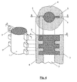
- the partially sectioned side view of the bone 6 with the implanted shaft 1 shows newly ossified zones 3 and 5 of the bone's walls 8 , and serves to demonstrate how the device is integrated with the bone at the end of the healing process.
- the top view shows the shaft 1 after healing, following the shaft's installation into the pre-drilled cylindrical cavity in the medullary canal, and into the pre-cut slots 4 that extend entirely through the thickness of the walls 8 .
- FIG. 5 presents a 3D view of a guide 9 with slots 4 , which frame the interior of the section of bone to be excised from the bone walls 8 , once the guide is inserted into the pre-drilled cylindrical cavity in the medullary canal (see FIG. 4 ).
- the device in the present invention namely, the implantable shaft of the prosthetic joint or the abutment for the attachment of an external limb prosthesis, has a central portion 1 situated in the cavity of the medullary canal 7 of the bone 6 .
- the side elements 2 of this device are situated in the slots 4 pre-cut out of the walls 8 of the bone.
- the method of installation of the device is also a component of the present invention, and is implemented once the marrow cavity of the bone is which implantation is planned is prepared in the conventional manner (by drilling a cavity in the medullary canal 7 ).
- a guide 9 with slots 14 (see FIG. 5 ) is inserted into a pre-drilled cavity in the medullary canal 7 .
- the diameter of the drill that prepares the cylindrical cavity has to correspond to the diameter of the cavity and the depth of drilling should correspond to the height of the shaft 1 to allow the guide to be easily inserted and removed manually without additional tools.
- the slots 14 of the guide 9 should be oriented in the sagittal plane or otherwise depending on the patient's conditions.
- the surgical saw is positioned against the slots of the guide and the cut is performed through the bone's walls 8 down to the limit provided by the depth of the slots 14 of the guide.
- the guide is removed from the cavity, and the shaft 1 is implanted from the open end of the bone by positioning the side elements 2 against the slots just made in the walls 8 . Insertion of the shaft should be performed carefully in order not to split the bone.
- the thickness of the side elements can approximate the width of the slots and may slightly exceed the width of the slots.
- the width of each side element can approximate the thickness of the bone's wall such that after installation, the side elements do not extend beyond the outer circumference of the bone.
- the described method of installation of the shaft activate the ossification of the bone inside the free spaces of the slots 4 , which form the newly formed zones 3 and 5 with the locking effect with respect to the shaft 1 and the implant, for which the shaft 1 is a supporting element.
- the invention relates to an implantable shaft for prosthetic joints or for direct skeletal attachment of external limb prostheses, comprised of a central body fitted in the bone's medullary cavity conventionally prepared for implantation, and of side elements attached to the central body and fitted in the slots specially made in the bone's walls surrounding the medullary canal, and the side elements have spaces between them.
- the side elements are lined along the longitudinal direction of the bone.
- the thickness of the elements approximates the width of the slots and may slightly exceed the thickness of the width of the slots.
- the width of each element approximates the thickness of the bone's wall such that after installation, the elements do not extend beyond the outer circumference of the bone.
- the invention relates to a method of preparing the bone for implantation of the prosthetic shaft, consisting of: placing a cylindrical guide with slots made in the longitudinal direction of the guide inside the bone's canal which is conventionally prepared for implantation; cutting the bone's walls by progressing a saw along the edges of the slots of the guide; removing the guide; fitting the shaft in the bone's canal, provided that the side elements are fitted to the slots in the bone's walls.
Abstract
Description
- 1. Kang, P., Shen, B., Yang, J., Cheng, J., Pei, F., Repairing Defect and Preventing Collapse of Canine Femoral Head Using Titanium Implant Enhanced by Autogenous Bone Graft and rhBMP-2. Connect Tissue Res, 2007. 48(4): p. 171-9.
- 2. Shuler, M. S., Rooks, M. D., Roberson, J. R., Porous tantalum implant in early osteonecrosis of the hip: preliminary report on operative, survival, and outcomes results. J Arthroplasty, 2007. 22(1): p. 26-31.
- 3. Nakamura, S., Kusuzaki, K, Murata, H., Takeshita, H., Hirata, M., Hashigushi, S., Hirasawa, Y., Bone reaction induced by femoral stem of titanium alloy endoprosthesis for malignant bone tumors at the distal femur. Oncol Rep, 2001. 8(4): p. 877-81.
- 4. Healy, W. L., Wasilewski, S. A., Takei, R., Oberlander, M., Patellofemoral complications following total knee arthroplasty. Correlation with implant design and patient risk factors. J Arthroplasty, 1995. 10(2): p. 197-201.
- 5. Bini, S. A., Johnston, J. O., Martin, D. L., Compliant prestress fixation in tumor prostheses: interface retrieval data. Orthopedics, 2000. 23(7): p. 707-11; discussion 711-2.
- 6. Brangnemark, P.-l., Anchoring element for implantation in tissue, for holding prosthesis, artificial joint components or the like. 1997: U.S. Pat. No. 5,702,445.
- 7. Burkinshaw, B., Kana, R., Combination tibial preparation instrumentation 2000: U.S. Pat. No. 6,159,216.
- 8. Kohler, M., Trachsler, T., Schwager, W., Bohler, N., Setting instrument for a tibia part of a knee joint prosthesis 2003: U.S. Pat. No. 6,520,966.
- 9. Gundlapalli, R., Goldstein, W., Marcoccio, D., Mccue, D., Method and apparatus for surgically preparing a tibia for implantation of a prosthetic implant component which has an offset stem, in U.S. Pat. No. 7,001,394 2006: U.S. Pat. No. 7,001,394.
- 10. Griss, P., Hipjointimplant. 1989: U.S. Pat. No. 4,828,566.
- 11. Ham, A. W., Cormack, D. H., Ham's histology. 9th ed. 1987, Philadelphia: Lippincott. xiv, p. 732.
- 12. Salter, R. B., Textbook of disorders and injuries of the musculoskeletal system: an introduction to orthopaedics, fractures, and joint injuries, rheumatology, metabolic bone disease, and rehabilitation. 3rd ed. 1999, Baltimore: Williams & Wilkins. xxxiv, p. 687.
- 13. Yun, A. G., Severino, R., Reinker, K., Attempted limb lengthenings beyond twenty percent of the initial bone length: results and complications. J Pediatr Orthop, 2000. 20(2): p. 151-9.
- 14. Price, C. T., Mann, J. W., Experience with the Orthofix device for limb lengthening. Orthop Clin NorthAm, 1991. 22(4): p. 651-61.
- 15. Ilizarov, G. A., The tension-stress effect on the genesis and growth of tissues. Part I. The influence of stability of fixation and soft-tissue preservation. Clin Orthop, 1989(238): p. 249-81.
- 16. Malik, Z. U., Hanif, M. S., Safdar, A., Masood, T., Planned external fixation to locked intramedullary nailing conversion for open fractures of shaft of femur and tibia. J Coli Physicians Surg Pak, 2005, 15(3): p. 133-6.
Claims (16)
Priority Applications (1)
| Application Number | Priority Date | Filing Date | Title |
|---|---|---|---|
| US14/050,523 US8992615B2 (en) | 2007-09-05 | 2013-10-10 | In-bone implantable shaft for prosthetic joints or for direct skeletal attachment of external limb prostheses and method of its installation |
Applications Claiming Priority (2)
| Application Number | Priority Date | Filing Date | Title |
|---|---|---|---|
| US11/899,068 US20090062928A1 (en) | 2007-09-05 | 2007-09-05 | In-bone implantable shaft for prosthetic joints or for direct skeletal attachment of external limb prostheses and method of its installation |
| US14/050,523 US8992615B2 (en) | 2007-09-05 | 2013-10-10 | In-bone implantable shaft for prosthetic joints or for direct skeletal attachment of external limb prostheses and method of its installation |
Related Parent Applications (1)
| Application Number | Title | Priority Date | Filing Date |
|---|---|---|---|
| US11/899,068 Continuation US20090062928A1 (en) | 2007-09-05 | 2007-09-05 | In-bone implantable shaft for prosthetic joints or for direct skeletal attachment of external limb prostheses and method of its installation |
Publications (2)
| Publication Number | Publication Date |
|---|---|
| US20140135942A1 US20140135942A1 (en) | 2014-05-15 |
| US8992615B2 true US8992615B2 (en) | 2015-03-31 |
Family
ID=40408718
Family Applications (2)
| Application Number | Title | Priority Date | Filing Date |
|---|---|---|---|
| US11/899,068 Abandoned US20090062928A1 (en) | 2007-09-05 | 2007-09-05 | In-bone implantable shaft for prosthetic joints or for direct skeletal attachment of external limb prostheses and method of its installation |
| US14/050,523 Active - Reinstated US8992615B2 (en) | 2007-09-05 | 2013-10-10 | In-bone implantable shaft for prosthetic joints or for direct skeletal attachment of external limb prostheses and method of its installation |
Family Applications Before (1)
| Application Number | Title | Priority Date | Filing Date |
|---|---|---|---|
| US11/899,068 Abandoned US20090062928A1 (en) | 2007-09-05 | 2007-09-05 | In-bone implantable shaft for prosthetic joints or for direct skeletal attachment of external limb prostheses and method of its installation |
Country Status (1)
| Country | Link |
|---|---|
| US (2) | US20090062928A1 (en) |
Cited By (5)
| Publication number | Priority date | Publication date | Assignee | Title |
|---|---|---|---|---|
| US20150366668A1 (en) * | 2014-06-23 | 2015-12-24 | Community Blood Center | Cellular-scale surface modification for increased osteogenic protein expression |
| US10136929B2 (en) | 2015-07-13 | 2018-11-27 | IntraFuse, LLC | Flexible bone implant |
| US10154863B2 (en) | 2015-07-13 | 2018-12-18 | IntraFuse, LLC | Flexible bone screw |
| US10485595B2 (en) | 2015-07-13 | 2019-11-26 | IntraFuse, LLC | Flexible bone screw |
| US10499960B2 (en) | 2015-07-13 | 2019-12-10 | IntraFuse, LLC | Method of bone fixation |
Families Citing this family (4)
| Publication number | Priority date | Publication date | Assignee | Title |
|---|---|---|---|---|
| US7909883B2 (en) * | 2007-02-21 | 2011-03-22 | Sidebotham Christopher G | Percutaneous implant for limb salvage |
| US20150018964A1 (en) * | 2013-07-09 | 2015-01-15 | Arthrex, Inc. | Bone void plugs and methods of use |
| CA2954631A1 (en) | 2014-07-31 | 2016-02-04 | Dow Agrosciences Llc | Process for the preparation of 3-(3-chloro-1h-pyrazol-1-yl)pyridine |
| MA41535B1 (en) * | 2017-11-27 | 2019-10-31 | Mohamed Faoussi | Osteointegrated orthopedic implant intended for femoral amputations with short stumps |
Citations (34)
| Publication number | Priority date | Publication date | Assignee | Title |
|---|---|---|---|---|
| US2765787A (en) | 1954-08-02 | 1956-10-09 | Leon L Pellet | Hip arthroplasty with flexible securing means |
| US3996625A (en) | 1975-02-28 | 1976-12-14 | United States Surgical Corporation | Artificial hip joint with novel stem |
| US4164794A (en) | 1977-04-14 | 1979-08-21 | Union Carbide Corporation | Prosthetic devices having coatings of selected porous bioengineering thermoplastics |
| US4231120A (en) | 1977-09-22 | 1980-11-04 | National Research Development Corporation | Endoprosthetic orthopaedic devices |
| US4403607A (en) | 1980-05-09 | 1983-09-13 | The Regents Of The University Of California | Compatible internal bone fixation plate |
| US4608053A (en) * | 1982-05-03 | 1986-08-26 | Waldemar Link Gmbh & Co. | Femoral hip prosthesis |
| US4828566A (en) | 1986-02-18 | 1989-05-09 | Sulzer Brothers Limited | Hip joint implant |
| US4938770A (en) | 1988-10-27 | 1990-07-03 | Sulzer Brothers Limited | Stem for a femoral head prosthesis |
| US5324199A (en) | 1990-05-25 | 1994-06-28 | Medevelop Ab | Fixture for anchoring in bone tissue |
| US5480453A (en) * | 1992-11-20 | 1996-01-02 | Burke; Dennis W. | Collar for femoral implant and method and apparatus for installation thereof |
| US5658351A (en) | 1995-07-31 | 1997-08-19 | Howmedica Inc. | Intramedullary centralizer |
| US5702445A (en) | 1993-04-27 | 1997-12-30 | Medevelop Ab | Anchoring element for implantation in tissue, for holding prosthesis, artificial joint components or the like |
| US5716361A (en) * | 1995-11-02 | 1998-02-10 | Masini; Michael A. | Bone cutting guides for use in the implantation of prosthetic joint components |
| US6159216A (en) | 1998-09-09 | 2000-12-12 | Sulzer Orthopedics Inc. | Combination tibial preparation instrumentation |
| US6290724B1 (en) | 1998-05-27 | 2001-09-18 | Nuvasive, Inc. | Methods for separating and stabilizing adjacent vertebrae |
| US6290726B1 (en) * | 2000-01-30 | 2001-09-18 | Diamicron, Inc. | Prosthetic hip joint having sintered polycrystalline diamond compact articulation surfaces |
| US20010047207A1 (en) | 1998-10-30 | 2001-11-29 | Michelson Gary K. | Self-broaching, rotatable, push-in interbody spinal fusion implant and method for deployment thereof |
| US20020099445A1 (en) | 2001-01-23 | 2002-07-25 | Maroney Brian J. | Method and apparatus for performing a shoulder replacement procedure in the treatment of cuff tear arthropathy |
| US20020099381A1 (en) | 2001-01-23 | 2002-07-25 | Maroney Brian J. | Method and apparatus for resecting a greater tubercle from a humerus of a patient during performance of a shoulder replacement procedure |
| US6436139B1 (en) | 1999-02-04 | 2002-08-20 | Sdgi Holdings, Inc. | Interbody fusion device with anti-rotation features |
| US6520966B1 (en) | 1999-09-21 | 2003-02-18 | Sulzer Orthopedics Ltd. | Setting instrument for a tibia part of a knee joint prosthesis |
| US20030078668A1 (en) | 1999-05-05 | 2003-04-24 | Michelson Gary K. | Interbody spinal fusion implants with single-lock for locking opposed screws |
| US6740120B1 (en) | 1996-08-13 | 2004-05-25 | James B. Grimes | Bone prosthesis and method of Access |
| US6752833B2 (en) | 2000-02-18 | 2004-06-22 | Isotis N.V. | Plug for insertion into a bone canal |
| US20050143827A1 (en) | 1999-01-27 | 2005-06-30 | Disco-O-Tech Medical Technologies Ltd. | Expandable intervertebral spacer |
| US20050177241A1 (en) | 2004-02-05 | 2005-08-11 | Laurent Angibaud | Shoulder prosthesis with humeral fracture stem |
| US7001394B2 (en) | 2000-12-28 | 2006-02-21 | Depuy Products, Inc. | Method and apparatus for surgically preparing a tibia for implantation of a prosthetic implant component which has an offset stem |
| US20070050032A1 (en) | 2005-09-01 | 2007-03-01 | Spinal Kinetics, Inc. | Prosthetic intervertebral discs |
| US20070050033A1 (en) | 2005-09-01 | 2007-03-01 | Reo Michael L | Prosthetic intervertebral discs |
| US20070198088A1 (en) | 2003-10-17 | 2007-08-23 | Lutz Biedermann | Flexible implant |
| US20070255421A1 (en) | 2006-04-27 | 2007-11-01 | Sdgi Holdings, Inc. | Locking expandable implant and method |
| US20070282443A1 (en) | 1997-03-07 | 2007-12-06 | Disc-O-Tech Medical Technologies Ltd. | Expandable element |
| US20080033569A1 (en) | 2004-04-19 | 2008-02-07 | Searete Llc, A Limited Liability Corporation Of The State Of Delaware | Bioelectromagnetic interface system |
| US7556648B2 (en) | 1997-05-20 | 2009-07-07 | George J. Picha | Spinal implant |
-
2007
- 2007-09-05 US US11/899,068 patent/US20090062928A1/en not_active Abandoned
-
2013
- 2013-10-10 US US14/050,523 patent/US8992615B2/en active Active - Reinstated
Patent Citations (40)
| Publication number | Priority date | Publication date | Assignee | Title |
|---|---|---|---|---|
| US2765787A (en) | 1954-08-02 | 1956-10-09 | Leon L Pellet | Hip arthroplasty with flexible securing means |
| US3996625A (en) | 1975-02-28 | 1976-12-14 | United States Surgical Corporation | Artificial hip joint with novel stem |
| US4164794A (en) | 1977-04-14 | 1979-08-21 | Union Carbide Corporation | Prosthetic devices having coatings of selected porous bioengineering thermoplastics |
| US4231120A (en) | 1977-09-22 | 1980-11-04 | National Research Development Corporation | Endoprosthetic orthopaedic devices |
| US4403607A (en) | 1980-05-09 | 1983-09-13 | The Regents Of The University Of California | Compatible internal bone fixation plate |
| US4608053A (en) * | 1982-05-03 | 1986-08-26 | Waldemar Link Gmbh & Co. | Femoral hip prosthesis |
| US4828566A (en) | 1986-02-18 | 1989-05-09 | Sulzer Brothers Limited | Hip joint implant |
| US4938770A (en) | 1988-10-27 | 1990-07-03 | Sulzer Brothers Limited | Stem for a femoral head prosthesis |
| US5324199A (en) | 1990-05-25 | 1994-06-28 | Medevelop Ab | Fixture for anchoring in bone tissue |
| US5480453A (en) * | 1992-11-20 | 1996-01-02 | Burke; Dennis W. | Collar for femoral implant and method and apparatus for installation thereof |
| US5702445A (en) | 1993-04-27 | 1997-12-30 | Medevelop Ab | Anchoring element for implantation in tissue, for holding prosthesis, artificial joint components or the like |
| US5658351A (en) | 1995-07-31 | 1997-08-19 | Howmedica Inc. | Intramedullary centralizer |
| US5716361A (en) * | 1995-11-02 | 1998-02-10 | Masini; Michael A. | Bone cutting guides for use in the implantation of prosthetic joint components |
| US6740120B1 (en) | 1996-08-13 | 2004-05-25 | James B. Grimes | Bone prosthesis and method of Access |
| US20070282443A1 (en) | 1997-03-07 | 2007-12-06 | Disc-O-Tech Medical Technologies Ltd. | Expandable element |
| US7556648B2 (en) | 1997-05-20 | 2009-07-07 | George J. Picha | Spinal implant |
| US6290724B1 (en) | 1998-05-27 | 2001-09-18 | Nuvasive, Inc. | Methods for separating and stabilizing adjacent vertebrae |
| US6159216A (en) | 1998-09-09 | 2000-12-12 | Sulzer Orthopedics Inc. | Combination tibial preparation instrumentation |
| US20010047207A1 (en) | 1998-10-30 | 2001-11-29 | Michelson Gary K. | Self-broaching, rotatable, push-in interbody spinal fusion implant and method for deployment thereof |
| US7056342B2 (en) | 1998-10-30 | 2006-06-06 | Sdgi Holdings, Inc. | Self-broaching, rotatable, push-in interbody spinal fusion implant and method for deployment thereof |
| US20050143827A1 (en) | 1999-01-27 | 2005-06-30 | Disco-O-Tech Medical Technologies Ltd. | Expandable intervertebral spacer |
| US20020193881A1 (en) | 1999-02-04 | 2002-12-19 | Shapiro David E. | Interbody fusion device with anti-rotation features |
| US6436139B1 (en) | 1999-02-04 | 2002-08-20 | Sdgi Holdings, Inc. | Interbody fusion device with anti-rotation features |
| US7041135B2 (en) | 1999-05-05 | 2006-05-09 | Sdgi Holdings, Inc. | Interbody spinal fusion implants with single-lock for locking opposed screws |
| US6558423B1 (en) | 1999-05-05 | 2003-05-06 | Gary K. Michelson | Interbody spinal fusion implants with multi-lock for locking opposed screws |
| US20030199983A1 (en) | 1999-05-05 | 2003-10-23 | Michelson Gary K. | Interbody spinal fusion implants with end cap for locking vertebral body penetrating members |
| US20030078668A1 (en) | 1999-05-05 | 2003-04-24 | Michelson Gary K. | Interbody spinal fusion implants with single-lock for locking opposed screws |
| US6520966B1 (en) | 1999-09-21 | 2003-02-18 | Sulzer Orthopedics Ltd. | Setting instrument for a tibia part of a knee joint prosthesis |
| US6290726B1 (en) * | 2000-01-30 | 2001-09-18 | Diamicron, Inc. | Prosthetic hip joint having sintered polycrystalline diamond compact articulation surfaces |
| US6752833B2 (en) | 2000-02-18 | 2004-06-22 | Isotis N.V. | Plug for insertion into a bone canal |
| US20040176854A1 (en) | 2000-02-18 | 2004-09-09 | Isotis N.V. | Plug for insertion into a bone canal |
| US7001394B2 (en) | 2000-12-28 | 2006-02-21 | Depuy Products, Inc. | Method and apparatus for surgically preparing a tibia for implantation of a prosthetic implant component which has an offset stem |
| US20020099381A1 (en) | 2001-01-23 | 2002-07-25 | Maroney Brian J. | Method and apparatus for resecting a greater tubercle from a humerus of a patient during performance of a shoulder replacement procedure |
| US20020099445A1 (en) | 2001-01-23 | 2002-07-25 | Maroney Brian J. | Method and apparatus for performing a shoulder replacement procedure in the treatment of cuff tear arthropathy |
| US20070198088A1 (en) | 2003-10-17 | 2007-08-23 | Lutz Biedermann | Flexible implant |
| US20050177241A1 (en) | 2004-02-05 | 2005-08-11 | Laurent Angibaud | Shoulder prosthesis with humeral fracture stem |
| US20080033569A1 (en) | 2004-04-19 | 2008-02-07 | Searete Llc, A Limited Liability Corporation Of The State Of Delaware | Bioelectromagnetic interface system |
| US20070050032A1 (en) | 2005-09-01 | 2007-03-01 | Spinal Kinetics, Inc. | Prosthetic intervertebral discs |
| US20070050033A1 (en) | 2005-09-01 | 2007-03-01 | Reo Michael L | Prosthetic intervertebral discs |
| US20070255421A1 (en) | 2006-04-27 | 2007-11-01 | Sdgi Holdings, Inc. | Locking expandable implant and method |
Non-Patent Citations (2)
| Title |
|---|
| Jae-Young Rho et al.; Mechanical properties and the hierarchical structure of bone; Medical Engineering & Physics (1998) 20, 92-102. |
| Peter Munger et al.; Patient-related risk factors leading to aseptic stem loosening in total hip arthroplasty; ActaOrthopaedica (2006) 77(4),567-574. |
Cited By (6)
| Publication number | Priority date | Publication date | Assignee | Title |
|---|---|---|---|---|
| US20150366668A1 (en) * | 2014-06-23 | 2015-12-24 | Community Blood Center | Cellular-scale surface modification for increased osteogenic protein expression |
| US10136929B2 (en) | 2015-07-13 | 2018-11-27 | IntraFuse, LLC | Flexible bone implant |
| US10154863B2 (en) | 2015-07-13 | 2018-12-18 | IntraFuse, LLC | Flexible bone screw |
| US10485595B2 (en) | 2015-07-13 | 2019-11-26 | IntraFuse, LLC | Flexible bone screw |
| US10492838B2 (en) | 2015-07-13 | 2019-12-03 | IntraFuse, LLC | Flexible bone implant |
| US10499960B2 (en) | 2015-07-13 | 2019-12-10 | IntraFuse, LLC | Method of bone fixation |
Also Published As
| Publication number | Publication date |
|---|---|
| US20090062928A1 (en) | 2009-03-05 |
| US20140135942A1 (en) | 2014-05-15 |
Similar Documents
| Publication | Publication Date | Title |
|---|---|---|
| US8992615B2 (en) | In-bone implantable shaft for prosthetic joints or for direct skeletal attachment of external limb prostheses and method of its installation | |
| US11406508B2 (en) | Flexible elongated chain implant and method of supporting body tissue with same | |
| US20110306975A1 (en) | Arrangement for internal bone support | |
| US8142462B2 (en) | Instruments and methods for reducing and stabilizing bone fractures | |
| US6755862B2 (en) | Intramedullary support strut | |
| AU2014321170B2 (en) | Intramedullary support with porous metal splines | |
| US9439704B2 (en) | Methods and devices for bone preparation | |
| US6981991B2 (en) | Arthroplasty devices configured to reduce shear stress | |
| US8647391B2 (en) | Malleolar replacement devices | |
| US20100331842A1 (en) | Multi-articulated fracture fixation device with adjustable modulus of rigidity | |
| US20070118219A1 (en) | Transosseous spine core approach method implant and instrumentation | |
| US20070005146A1 (en) | Hip stem for receiving intramedullary nail | |
| US8778029B2 (en) | Implantable prosthesis for replacing a human hip or knee joint and the adjoining bone sections | |
| US4851004A (en) | Implantation of articulating joint prosthesis | |
| AU2016353265B2 (en) | Joint implants and methods | |
| GB2118441A (en) | Articulating joint prostheses | |
| RU2301049C2 (en) | Hip joint endoprosthesis | |
| US20200197063A1 (en) | Bone Filling Systems, Devices, and Methods of Use | |
| US9763708B2 (en) | Intramedullary fixation device |
Legal Events
| Date | Code | Title | Description |
|---|---|---|---|
| ZAAA | Notice of allowance and fees due |
Free format text: ORIGINAL CODE: NOA |
|
| ZAAB | Notice of allowance mailed |
Free format text: ORIGINAL CODE: MN/=. |
|
| STCF | Information on status: patent grant |
Free format text: PATENTED CASE |
|
| MAFP | Maintenance fee payment |
Free format text: PAYMENT OF MAINTENANCE FEE, 4TH YR, SMALL ENTITY (ORIGINAL EVENT CODE: M2551); ENTITY STATUS OF PATENT OWNER: SMALL ENTITY Year of fee payment: 4 |
|
| FEPP | Fee payment procedure |
Free format text: MAINTENANCE FEE REMINDER MAILED (ORIGINAL EVENT CODE: REM.); ENTITY STATUS OF PATENT OWNER: SMALL ENTITY |
|
| LAPS | Lapse for failure to pay maintenance fees |
Free format text: PATENT EXPIRED FOR FAILURE TO PAY MAINTENANCE FEES (ORIGINAL EVENT CODE: EXP.); ENTITY STATUS OF PATENT OWNER: SMALL ENTITY |
|
| STCH | Information on status: patent discontinuation |
Free format text: PATENT EXPIRED DUE TO NONPAYMENT OF MAINTENANCE FEES UNDER 37 CFR 1.362 |
|
| FP | Lapsed due to failure to pay maintenance fee |
Effective date: 20230331 |
|
| PRDP | Patent reinstated due to the acceptance of a late maintenance fee |
Effective date: 20240301 |
|
| FEPP | Fee payment procedure |
Free format text: PETITION RELATED TO MAINTENANCE FEES FILED (ORIGINAL EVENT CODE: PMFP); ENTITY STATUS OF PATENT OWNER: SMALL ENTITY Free format text: PETITION RELATED TO MAINTENANCE FEES GRANTED (ORIGINAL EVENT CODE: PMFG); ENTITY STATUS OF PATENT OWNER: SMALL ENTITY Free format text: SURCHARGE, PETITION TO ACCEPT PYMT AFTER EXP, UNINTENTIONAL. (ORIGINAL EVENT CODE: M2558); ENTITY STATUS OF PATENT OWNER: SMALL ENTITY |
|
| MAFP | Maintenance fee payment |
Free format text: PAYMENT OF MAINTENANCE FEE, 8TH YR, SMALL ENTITY (ORIGINAL EVENT CODE: M2552); ENTITY STATUS OF PATENT OWNER: SMALL ENTITY Year of fee payment: 8 |
|
| STCF | Information on status: patent grant |
Free format text: PATENTED CASE |