US8993080B2 - Peelable sealant containing thermoplastic composite blends for packaging applications - Google Patents
Peelable sealant containing thermoplastic composite blends for packaging applications Download PDFInfo
- Publication number
- US8993080B2 US8993080B2 US12/983,732 US98373211A US8993080B2 US 8993080 B2 US8993080 B2 US 8993080B2 US 98373211 A US98373211 A US 98373211A US 8993080 B2 US8993080 B2 US 8993080B2
- Authority
- US
- United States
- Prior art keywords
- organoclay
- packaging system
- calcium carbonate
- sealing layer
- thermoplastic polymer
- Prior art date
- Legal status (The legal status is an assumption and is not a legal conclusion. Google has not performed a legal analysis and makes no representation as to the accuracy of the status listed.)
- Active
Links
Images


Classifications
-
- B—PERFORMING OPERATIONS; TRANSPORTING
- B32—LAYERED PRODUCTS
- B32B—LAYERED PRODUCTS, i.e. PRODUCTS BUILT-UP OF STRATA OF FLAT OR NON-FLAT, e.g. CELLULAR OR HONEYCOMB, FORM
- B32B27/00—Layered products comprising a layer of synthetic resin
- B32B27/06—Layered products comprising a layer of synthetic resin as the main or only constituent of a layer, which is next to another layer of the same or of a different material
- B32B27/08—Layered products comprising a layer of synthetic resin as the main or only constituent of a layer, which is next to another layer of the same or of a different material of synthetic resin
-
- B—PERFORMING OPERATIONS; TRANSPORTING
- B32—LAYERED PRODUCTS
- B32B—LAYERED PRODUCTS, i.e. PRODUCTS BUILT-UP OF STRATA OF FLAT OR NON-FLAT, e.g. CELLULAR OR HONEYCOMB, FORM
- B32B27/00—Layered products comprising a layer of synthetic resin
- B32B27/18—Layered products comprising a layer of synthetic resin characterised by the use of special additives
- B32B27/20—Layered products comprising a layer of synthetic resin characterised by the use of special additives using fillers, pigments, thixotroping agents
-
- B—PERFORMING OPERATIONS; TRANSPORTING
- B32—LAYERED PRODUCTS
- B32B—LAYERED PRODUCTS, i.e. PRODUCTS BUILT-UP OF STRATA OF FLAT OR NON-FLAT, e.g. CELLULAR OR HONEYCOMB, FORM
- B32B7/00—Layered products characterised by the relation between layers; Layered products characterised by the relative orientation of features between layers, or by the relative values of a measurable parameter between layers, i.e. products comprising layers having different physical, chemical or physicochemical properties; Layered products characterised by the interconnection of layers
- B32B7/04—Interconnection of layers
- B32B7/06—Interconnection of layers permitting easy separation
-
- B—PERFORMING OPERATIONS; TRANSPORTING
- B65—CONVEYING; PACKING; STORING; HANDLING THIN OR FILAMENTARY MATERIAL
- B65D—CONTAINERS FOR STORAGE OR TRANSPORT OF ARTICLES OR MATERIALS, e.g. BAGS, BARRELS, BOTTLES, BOXES, CANS, CARTONS, CRATES, DRUMS, JARS, TANKS, HOPPERS, FORWARDING CONTAINERS; ACCESSORIES, CLOSURES, OR FITTINGS THEREFOR; PACKAGING ELEMENTS; PACKAGES
- B65D75/00—Packages comprising articles or materials partially or wholly enclosed in strips, sheets, blanks, tubes, or webs of flexible sheet material, e.g. in folded wrappers
- B65D75/52—Details
- B65D75/58—Opening or contents-removing devices added or incorporated during package manufacture
- B65D75/5855—Peelable seals
-
- B—PERFORMING OPERATIONS; TRANSPORTING
- B65—CONVEYING; PACKING; STORING; HANDLING THIN OR FILAMENTARY MATERIAL
- B65D—CONTAINERS FOR STORAGE OR TRANSPORT OF ARTICLES OR MATERIALS, e.g. BAGS, BARRELS, BOTTLES, BOXES, CANS, CARTONS, CRATES, DRUMS, JARS, TANKS, HOPPERS, FORWARDING CONTAINERS; ACCESSORIES, CLOSURES, OR FITTINGS THEREFOR; PACKAGING ELEMENTS; PACKAGES
- B65D77/00—Packages formed by enclosing articles or materials in preformed containers, e.g. boxes, cartons, sacks or bags
- B65D77/10—Container closures formed after filling
- B65D77/20—Container closures formed after filling by applying separate lids or covers, i.e. flexible membrane or foil-like covers
- B65D77/2024—Container closures formed after filling by applying separate lids or covers, i.e. flexible membrane or foil-like covers the cover being welded or adhered to the container
- B65D77/2028—Means for opening the cover other than, or in addition to, a pull tab
- B65D77/2032—Means for opening the cover other than, or in addition to, a pull tab by peeling or tearing the cover from the container
-
- B—PERFORMING OPERATIONS; TRANSPORTING
- B32—LAYERED PRODUCTS
- B32B—LAYERED PRODUCTS, i.e. PRODUCTS BUILT-UP OF STRATA OF FLAT OR NON-FLAT, e.g. CELLULAR OR HONEYCOMB, FORM
- B32B2264/00—Composition or properties of particles which form a particulate layer or are present as additives
- B32B2264/10—Inorganic particles
- B32B2264/104—Oxysalt, e.g. carbonate, sulfate, phosphate or nitrate particles
-
- B—PERFORMING OPERATIONS; TRANSPORTING
- B32—LAYERED PRODUCTS
- B32B—LAYERED PRODUCTS, i.e. PRODUCTS BUILT-UP OF STRATA OF FLAT OR NON-FLAT, e.g. CELLULAR OR HONEYCOMB, FORM
- B32B2264/00—Composition or properties of particles which form a particulate layer or are present as additives
- B32B2264/12—Mixture of at least two particles made of different materials
-
- B—PERFORMING OPERATIONS; TRANSPORTING
- B32—LAYERED PRODUCTS
- B32B—LAYERED PRODUCTS, i.e. PRODUCTS BUILT-UP OF STRATA OF FLAT OR NON-FLAT, e.g. CELLULAR OR HONEYCOMB, FORM
- B32B2307/00—Properties of the layers or laminate
- B32B2307/30—Properties of the layers or laminate having particular thermal properties
- B32B2307/302—Conductive
-
- B—PERFORMING OPERATIONS; TRANSPORTING
- B32—LAYERED PRODUCTS
- B32B—LAYERED PRODUCTS, i.e. PRODUCTS BUILT-UP OF STRATA OF FLAT OR NON-FLAT, e.g. CELLULAR OR HONEYCOMB, FORM
- B32B2307/00—Properties of the layers or laminate
- B32B2307/30—Properties of the layers or laminate having particular thermal properties
- B32B2307/31—Heat sealable
-
- B—PERFORMING OPERATIONS; TRANSPORTING
- B32—LAYERED PRODUCTS
- B32B—LAYERED PRODUCTS, i.e. PRODUCTS BUILT-UP OF STRATA OF FLAT OR NON-FLAT, e.g. CELLULAR OR HONEYCOMB, FORM
- B32B2439/00—Containers; Receptacles
- B32B2439/40—Closed containers
-
- B—PERFORMING OPERATIONS; TRANSPORTING
- B32—LAYERED PRODUCTS
- B32B—LAYERED PRODUCTS, i.e. PRODUCTS BUILT-UP OF STRATA OF FLAT OR NON-FLAT, e.g. CELLULAR OR HONEYCOMB, FORM
- B32B2439/00—Containers; Receptacles
- B32B2439/40—Closed containers
- B32B2439/46—Bags
-
- B—PERFORMING OPERATIONS; TRANSPORTING
- B65—CONVEYING; PACKING; STORING; HANDLING THIN OR FILAMENTARY MATERIAL
- B65D—CONTAINERS FOR STORAGE OR TRANSPORT OF ARTICLES OR MATERIALS, e.g. BAGS, BARRELS, BOTTLES, BOXES, CANS, CARTONS, CRATES, DRUMS, JARS, TANKS, HOPPERS, FORWARDING CONTAINERS; ACCESSORIES, CLOSURES, OR FITTINGS THEREFOR; PACKAGING ELEMENTS; PACKAGES
- B65D2575/00—Packages comprising articles or materials partially or wholly enclosed in strips, sheets, blanks, tubes or webs of flexible sheet material, e.g. in folded wrappers
- B65D2575/28—Articles or materials wholly enclosed in composite wrappers, i.e. wrappers formed by association or interconnecting two or more sheets or blanks
- B65D2575/30—Articles or materials enclosed between two opposed sheets or blanks having their margins united, e.g. by pressure-sensitive adhesive, crimping, heat-sealing, or welding
- B65D2575/32—Articles or materials enclosed between two opposed sheets or blanks having their margins united, e.g. by pressure-sensitive adhesive, crimping, heat-sealing, or welding one or both sheets or blanks being recessed to accommodate contents
- B65D2575/3209—Details
- B65D2575/3218—Details with special means for gaining access to the contents
- B65D2575/3245—Details with special means for gaining access to the contents by peeling off the non-rigid sheet
-
- Y—GENERAL TAGGING OF NEW TECHNOLOGICAL DEVELOPMENTS; GENERAL TAGGING OF CROSS-SECTIONAL TECHNOLOGIES SPANNING OVER SEVERAL SECTIONS OF THE IPC; TECHNICAL SUBJECTS COVERED BY FORMER USPC CROSS-REFERENCE ART COLLECTIONS [XRACs] AND DIGESTS
- Y10—TECHNICAL SUBJECTS COVERED BY FORMER USPC
- Y10T—TECHNICAL SUBJECTS COVERED BY FORMER US CLASSIFICATION
- Y10T428/00—Stock material or miscellaneous articles
- Y10T428/13—Hollow or container type article [e.g., tube, vase, etc.]
- Y10T428/1352—Polymer or resin containing [i.e., natural or synthetic]
Definitions
- the present invention relates to package systems that include a peelable seal and, in particular, the present invention relates to compositions and methods for forming such peelable seals.
- Packaging is an important feature in protecting, selling and marketing most products. Packaging has broad applications, for example, in food products, medical devices, electronic components, industrial products, personal hygiene products, pet products, collectibles, jewelry, and the like. The specific features of such packaging will require properties for the particular application. For example, medical products and food products may often require a hermetic seal in order to prevent contamination of the product contained therein.
- Food products in particular, have rather stringent packaging requirements in order to preserve freshness and provide desired shelf life.
- Certain medical devices also demand strict packaging requirements in order to preserve sterility of such devices.
- the package is typically vacuum-packed or gas-flushed and subsequently hermetically sealed.
- efficient packaging of products is mandatory, various aesthetic properties of a product package are also important. For example, the package appearance is highly important to consumer appeal.
- functional properties of the packaging such as reusability and ease of opening of a package are important considerations.
- the ability to easily open a package will depend on the mechanical properties of the seal.
- the ability of the sealant substrate to transfer heat at a high rate results in a significant reduction of seal dwell time, and enables higher cycle speed and lower energy consumption, of sealing processes with total material reduction (sustainability).
- One such packaging structure utilizes a peelable seal.
- a sealing layer may be peeled away from a substrate. It is desirable for such peeling to be achievable with a low and relatively constant peel force.
- the elastic properties of the peelable seal ensure that failure of the seal does not occur from flexing and normal handling of the package.
- peelable seals are constructed from multi-layered sheets. Examples of packaging systems having such seals include standup and regular pouches, bag-in- ⁇ -box, tray-type food packages, bottles or blister packages, overwrap and the like.
- peelable sealing packages work reasonably well, it has been difficult to construct suitable packaging systems that will consistently form hermetic seals that resist leaking even when wrinkles, pleats, and gussets are present, and still be easily opened by an end user.
- Such earlier peelable packaging systems tend to operate over relatively narrow ranges, and, in particular, narrow temperature sealing ranges. Narrow sealing temperature ranges tend to result in packaging defects. For example, on the low end of the usable temperature range leaking seals may be formed (not hermetically sealed). On the high end of the usable temperature range, non-peelable seals are formed which tear when opened.
- the present invention solves one or more problems of the prior art by providing at least one embodiment of a packaging system having a peelable seal section.
- the peelable seal section includes a first sealing layer and a second sealing layer such that the first sealing layer contacts the second sealing layer to form a peelable seal.
- the first sealing layer includes a thermoplastic polymer, an organoclay dispersed within the thermoplastic polymer, and an additional additive component comprising inorganic filler, such as calcium carbonate dispersed within the thermoplastic polymer.
- the combined weight of the organoclay and the additional filler e.g., calcium carbonate
- the combined weight of the organoclay and the additional filler is from about 10 weight % to about 35 weight % of the combined weight of the thermoplastic polymer and the organoclay and the additional filler (e.g., calcium carbonate).
- the organoclay is present in an amount from 5 weight % to 20 weight % of the combined weight of the thermoplastic polymer and the organoclay and the additional filler (e.g., calcium carbonate).
- the inorganic filler such as calcium carbonate, is present in an amount from 6 weight % to 25 weight % of the combined weight of the thermoplastic polymer and the organoclay and the additional filler (e.g., calcium carbonate).
- the first sealing layer includes a sealing surface, the peelable seal having a peel force between 0.5 lbs and 5 lbs per inch of sealing width.
- the packaging system of the invention includes a container section and a peelable sealing section attached to the container section.
- the peelable seal section includes a first sealing layer and a second sealing layer such that the first sealing layer contacts the second sealing layer to form a peelable seal.
- the first sealing layer includes a thermoplastic polymer, an organoclay dispersed within the thermoplastic polymer, and an additional additive component comprising inorganic filler, such as calcium carbonate dispersed within the thermoplastic polymer.
- the combined weight of the organoclay and the additional filler e.g., calcium carbonate
- the combined weight of the organoclay and the additional filler is from about 10 weight % to about 35 weight % of the combined weight of the thermoplastic polymer and the organoclay and the additional filler (e.g., calcium carbonate).
- the organoclay is present in an amount from 5 weight % to 20 weight % of the combined weight of the thermoplastic polymer and the organoclay and the additional filler (e.g., calcium carbonate).
- the inorganic filler, such as calcium carbonate is present in an amount from 6 weight % to 25 weight % of the combined weight of the thermoplastic polymer and the organoclay and the calcium carbonate.
- the first sealing layer includes a sealing surface, the peelable seal having a peel force between 0.5 lbs and 5 lbs per inch of sealing width.
- a packaging system having a peelable seal section includes a sealing structure having formula 1: L 1 / . . . /L n /P (1) wherein P is a first sealing layer, L 1 through L n are layers within a support base upon which the sealing layer is disposed, and n is an integer representing the number of layers in the support base.
- the peelable seal section also includes a substrate such that the first sealing layer contacts the substrate to form a peelable seal, the first sealing layer includes a thermoplastic polymer, an organoclay dispersed within the thermoplastic polymer, and an additional additive component comprising inorganic filler, such as calcium carbonate, dispersed within the thermoplastic polymer.
- the combined weight of the organoclay and the additional filler is from about 10 weight % to about 35 weight % of the combined weight of the thermoplastic polymer and the organoclay and the additional filler (e.g., calcium carbonate).
- the organoclay is present in an amount from 5 weight % to 20 weight % of the combined weight of the thermoplastic polymer and the organoclay and the additional filler (e.g., calcium carbonate).
- the inorganic filler, such as calcium carbonate is present in an amount from 6 weight % to 25 weight % of the combined weight of the thermoplastic polymer and the organoclay and the calcium carbonate.
- the first sealing layer includes a sealing surface, the peelable seal having a peel force between 0.5 lbs and 5 lbs per inch of sealing width.
- a packaging system having a peelable seal section includes a sealing structure having formula 2: L 1 / . . . /L n /P/L f (2) wherein P is a first sealing layer, L 1 through L n represent layers within a support base upon which the sealing layer is disposed, L f is an additional layer disposed over the first sealing layer, and n is an integer representing the number of layers in the support base.
- the sealing section also includes a substrate such that the first sealing layer contacts the substrate to form a peelable seal.
- the first sealing layer includes a thermoplastic polymer, an organoclay dispersed within the thermoplastic polymer, and an additional additive component comprising inorganic filler, such as calcium carbonate, dispersed within the thermoplastic polymer.
- the combined weight of the organoclay and the additional filler e.g., calcium carbonate
- the organoclay is present in an amount from 5 weight % to 20 weight % of the combined weight of the thermoplastic polymer and the organoclay and the additional filler (e.g., calcium carbonate).
- the inorganic filler such as calcium carbonate
- the first sealing layer includes a sealing surface, the peelable seal having a peel force between 0.5 lbs and 5 lbs per inch of sealing width.
- a formulation for forming a peelable sealing layer contains an organoclay master batch and a calcium carbonate master batch with thermoplastic polymer(s).
- Packaging sealant systems formed from such formulations have synergistic effect and deliver peelablility over a broad range of sealing temperature, with better thermal conductivity and improved caulkability.
- such formulations (easy peel formulations in particular) have much better aging characteristics, without significant loss of desired peelable seal functionality as the seals age, comparing to polybutylene based easy open systems.
- FIG. 1A is a schematic cross-section of a single layer sealing structure that contains organoclay and an inorganic filler, such as calcium carbonate additives;
- FIG. 1B is a schematic cross-section of a two layer structure with an exterior organoclay/additional additive sealing layer
- FIG. 1C is a schematic cross-section of a three layer structure with an exterior organoclay/additional additive sealing layer
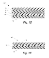
- FIG. 1D is a schematic cross-section of a five layer structure with an exterior organoclay/additional additive sealing layer
- FIG. 1E is a schematic cross-section of a three layer structure with an internal organoclay/additional additive sealing layer
- FIG. 2A is a schematic cross-section of a pouch-like packaging system incorporating an embodiment of the peelable sealing structure of the invention
- FIG. 2B is a side view of the pouch-like packaging system of FIG. 2A ;
- FIG. 2C is a side view of the pouch-like packaging system of FIG. 1E ;
- FIG. 3A is a schematic cross-section of a refinement in which a sealing substrate includes a second sealing layer
- FIG. 3B is a schematic cross-section of a refinement in which a sealing substrate includes a second sealing layer with a peelable seal being formed between a first sealing layer and a second sealing layer;
- FIG. 4A is a schematic cross-section of a cup-like packaging system that uses the peelable sealing structures of the invention.
- FIG. 4B is a schematic cross-section of a blister packaging system that uses the peelable sealing structures of the invention and incorporates multiple cup-like containers;
- FIG. 5 is a diagram illustrating a method of processing and layering sealant substrate layers of the invention and forming the package system
- FIG. 6 provides plots of the peel strength versus sealing temperature for seals made from a thermoplastic polymer/calcium carbonate composition and a thermoplastic polymer/organoclay composition
- FIG. 7 provides plots of the peel strength versus sealing temperature for seals made from compositions having varying amounts of organoclay and calcium carbonate;
- FIG. 8 provides plots of the peel strength versus sealing temperature for seals made from compositions having organoclay and high levels of calcium carbonate
- FIG. 9 provides plots of the peel strength versus sealing temperature for seals made from compositions having organoclay and metallocene; linear low-density polyethylene (LLDPE);
- FIG. 10 provides an illustration of the caulking test method in which caulking slope and ultimate sealing thickness is calculated
- FIG. 11 provides a plot of unsealed area versus contaminant thickness used to determine caulking slope and ultimate sealing thickness in the caulkability test method
- FIG. 12A provides a series of plots of unsealed area versus contaminant thickness for various polymer/organoclay/calcium carbonate combinations
- FIG. 12B provides the caulking slope for various film compositions
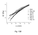
- FIGS. 13A and B provide plots of G′ and G′′ versus frequency (a T ⁇ ) for a number of compositions
- FIG. 14A provides a plot of caulking slope from G′/a T ⁇
- FIG. 14B provides a plot of the ultimate perfect seal thickness versus G′/a T ⁇
- FIG. 15 provides a plot of the ratio G′/a T ⁇ and the caulking slope for various samples.
- FIG. 16A-D provide plots of heat flow versus temperature for various film compositions.
- percent (%), “parts of,” and ratio values are by weight;
- the term “polymer” includes “oligomer,” “copolymer,” “terpolymer,” and the like;
- the description of a group or class of materials as suitable or preferred for a given purpose in connection with the invention implies that mixtures of any two or more of the members of the group or class are equally suitable or preferred;
- description of constituents in chemical terms refers to the constituents at the time of addition to any combination specified in the description, and does not necessarily preclude chemical interactions among the constituents of a mixture once mixed;
- the first definition of an acronym or other abbreviation applies to all subsequent uses herein of the same abbreviation and applies mutatis mutandis to normal grammatical variations of the initially defined abbreviation; and, unless expressly stated to the contrary, measurement of a property is determined by the same technique as previously or later referenced for the same property.
- organoclay as used herein means organically modified clay. Typically, such modification renders a clay to be more compatible and, therefore, blendable with polymers.
- clay layer(s) means individual layers of the layered material, such as smectite clay.
- exfoliated organoclay means that at least a portion of the organoclay includes a plurality of platelets in which the separation between the platelets is greater than the separation of platelets in unmodified clay and that at least a portion of the platelets are non-parallel. In typical unmodified clay, the adjacent platelets tend to be parallel. Typically, the average separation of an exfoliated organoclay will be greater than about 20 angstroms. Clays with average separations greater than about 100 nanometers are considered to be fully exfoliated. It should also be appreciated that the individual stacks of organoclay platelets may themselves be associated with other stacks to form an agglomeration of stacks. Such agglomerations are characterized by a maximum spatial dimension.
- the maximum spatial dimension is used to represent the organoclay distribution in polymer and polymer blends.
- a large value of the maximum spatial dimension represents good dispersion of the organoclay.
- the average maximum spatial dimension is from 1 nanometer to 100 microns. In refinement, the average maximum spatial dimension is from 1 nm to 100 nm. In another refinement, the average maximum spatial dimension is from 1 nm to 1000 nm. In another embodiment, the diameter is from 1 micron to 100 micron.
- nitrogen polymer or “neat polymer blend” as used herein means a thermoplastic polymer, or different types of thermoplastic polymer blends, that contain no inorganic filler.
- peelable seal means a seal that has a peel force of between 0.5 lbs to 5 lbs per one inch of sample width and a force that peels open the seal.
- the upper limit is less than or equal to 5 lbs per inch of sample width. In other variations, the upper limit is less than or equal to 4 lbs per inch of sample width or less than the tear strength on the film substrate.
- peel force means a force to separate two layers as defined in ASTM F-88, which is incorporated by reference. For example, this is the force necessary to separate two layers of one inch width by pulling the two layers apart.
- seal initiation temperature refers to the lowest temperature at which a seal is formed with a peel force of 0.5 lbs. per inch.
- the seal initiation temperature is the temperature of a surface (typically metal) contacting a layer or layers that are to be sealed thereby promoting such sealing.
- the surface contacts the layer(s) with a dwell time from about 0.1 to 2 seconds with a pressure from 5 psi to 1200 psi.
- peelable seal temperature range means the range of temperatures at which a seal between two materials is formed such that the peel force is between 0.5 lbs per one inch of sample width to 5 lbs per one inch of sample width with a force that tears the films as set forth above.
- sealing temperature means a temperature at which a seal is formed between two materials.
- caulking slope and “ultimate perfect sealing thickness” as used herein are defined as follows.
- a caulking test method introduces a gap with flat wire at a certain thickness (i.e., contaminant thickness) in the sealing region to simulate a contaminant inadvertently introduced near or in the sealing area during the heat seal process (see FIG. 10 ).
- the non-sealed area is measured using optical microscopy. A lower reading of the unsealed area represents better caulkability and enhanced ability to provide a hermetic seal.
- the non-sealed area is plotted as a function of contaminant thickness.
- the data is fit by linear regression (e.g., a least squares fit) with the caulking slope being the slope of the fitted line.
- the ultimate perfect sealing thickness is the contaminant thickness at a non-seal area of zero. A higher ultimate perfect sealing thickness indicates high caulkability.
- a peelable sealing structure is provided.
- the peelable sealing structure provides an improvement over the structures set forth in U.S. Pat. Pub. No. 2008/0118688, the entire disclosure of which is hereby incorporated by reference.
- the peelable seal section includes a first sealing layer and a second sealing layer such that the first sealing layer contacts the second sealing layer to form a peelable seal.
- the first sealing layer includes a thermoplastic polymer or a blend of thermoplastic polymers, an organoclay dispersed within the thermoplastic polymer or thermoplastic polymer blend, and an inorganic additive component such as calcium carbonate dispersed within the thermoplastic polymer or thermoplastic polymer blend.
- the combination of the organoclay and the calcium carbonate operates synergistically such that the first sealing layer produces a peelable seal when the first and second sealing layers are sealed together.
- some embodiments of the present invention advantageously form peelable seals that peel open via the Adhesive Type A failure mechanism.
- the peelable seals formed herein have a peel strength from 0.5 lbs per inch of sample width to 5 lbs per inch of sample width.
- the peelable seals formed herein have a peel strength from 1.0 lb per one inch of sample width to 4.5 lbs per inch of sample width.
- the peelable seals formed herein have a peel strength from 1.0 lb per one inch of sample width to 4.0 lbs per inch of sample width.
- the peelable seals formed herein are also characterized by a seal strength as set forth in ASTM F 88.
- the seal strength is tested and measured at the time a seal is formed.
- the preferred condition is to measure the seal strength within one minute of a newly formed peelable seal being cooled to room temperature.
- the peelable seals have a seal strength from 0.5 lbs to 5 lbs.
- the peelable seals have a seal strength from 1 lb to 3.5 lbs.
- the peelable seals of the present embodiment are also characterized by the caulking slope and the ultimate perfect sealing thickness (contaminant thickness).
- the caulking slope is less than or equal to 0.0032.
- the caulking slope is from 0.001 to 0.0032.
- the caulking slope is from 0.0026 to 0.0032.
- the caulking slope is from 0.0025 to 0.003.
- the caulking slope is from 0.0027 to 0.003.
- the ultimate perfect sealing thickness is greater than 5 microns.
- the ultimate perfect sealing thickness is from 5 microns to 400 microns.
- the ultimate perfect sealing thickness is from 5 microns to 300 microns.
- the caulking slope is less than about 0.003 and the ultimate seal thickness greater than about 5 microns.
- organoclay is a contributing component in peelable sealant formulation. It should be pointed out that without the organoclay, calcium carbonate does not produce a peelable seal. Moreover, the combination of organoclay and calcium carbonate requires less organoclay to produce a high quality peelable seal. Since the organoclay is a relatively expensive component as compared to calcium carbonate, the combination of organoclay and calcium carbonate offers considerable cost reduction.
- the combined weight of the organoclay and the calcium carbonate is from about 10 weight % to about 35 weight % of the combined weight of the thermoplastic polymer and the organoclay and the calcium carbonate.
- the organoclay is present in an amount from 5 weight % to 20 weight % of the combined weight of the thermoplastic polymer and the organoclay and the calcium carbonate.
- the calcium carbonate is present in an amount from 6 weight % to 25 weight % of the combined weight of the thermoplastic polymer and the organoclay and the calcium carbonate.
- the calcium carbonate to organic clay ratio ranges from 0.4 to 2.5.
- the first sealing layer includes a sealing surface that contacts a surface of the second sealing layer to form the peelable seal.
- the peelable seal is characterized by a peel force between 0.5 lbs and 5 lbs per inch of sealing width.
- the sealing surface is formable into a peelable seal at all temperatures within a peelable seal temperature range, that is, from a seal initiation temperature to a temperature that is at least 50° F. above the seal initiation temperature.
- the peelable seal temperature range is from a seal initiation temperature to a temperature that is at least 75° F. above the seal initiation temperature.
- the peelable seal temperature range is from a seal initiation temperature to a temperature that is at least 100° F. above the seal initiation temperature.
- the seal initiation temperature ranges from about 170° F. to about 420° F.
- the seal initiation temperature ranges from about 170° F. to about 350° F.
- the seal initiation temperature ranges from about 170° F. to about 270° F. All above temperature limits may vary with the heat resistance of the outer layers from lamination, co-extrusion, or coating. For example, when the outer layer is HDPE, the upper limit of seal temperature is about 270° F.; when the outer layer is oriented polyester, the upper temperature limit is about 420° F.
- the peelable sealing structures are multilayer structures that are useful for sealing applications.
- Such layered structures include a sealing layer that includes organoclay and an additional additive selected from the group consisting of calcium carbonate, magnesium carbonate, hydrated magnesium silicate (talc), titanium oxide, magnesium oxide, magnesium sulfate, barium sulfate, barium aluminates, barium borate, barium silicate and combinations thereof.
- organoclay selected from the group consisting of calcium carbonate, magnesium carbonate, hydrated magnesium silicate (talc), titanium oxide, magnesium oxide, magnesium sulfate, barium sulfate, barium aluminates, barium borate, barium silicate and combinations thereof.
- talc hydrated magnesium silicate
- L 1 through L n represent layers within a support base upon which the sealing layer is disposed, and n is an integer representing the number of layers in the support base.
- the support base usually includes one or more polymeric layers (rigid or flexible) as set forth below. Typically, n is an integer from 1 to 10.
- Examples of such multilayer structures have the following structures L 1 /P; L 1 /L 2 /P; L 1 /L 2 /L 3 /P; L 1 /L 2 /L 3 /L 4 /P; L 1 /L 2 /L 3 /L 4 /L 5 /P; L 1 /L 2 /L 3 /L 4 /L 5 /L 4 /L 5 /L 6 /P; and L 1 /L 2 /L 3 /L 4 /L 5 /L 4 /L 5 /L 6 /L 7 /P.
- Another variation of the multilayer sealing structure is described by formula 2: L 1 / . . .
- P is the sealing layer that includes organoclay and inorganic filler, such as calcium carbonate, and additional additive components
- L 1 through L n represent layers within a support base upon which the sealing layer is disposed
- L f is an additional non-peelable sealant polymeric layer disposed over the opposite side of P than L n
- n is an integer representing the number of layers in the support base.
- the support base usually includes one or more polymeric layers as set forth below. Typically, n is an integer from 1 to 10.
- Examples of such multilayer structures have the following structures L 1 /P/L f ; L 1 /L 2 /P/L f ; L 1 /L 2 /L 3 /P/L f ; L 1 /L 2 /L 3 /L 4 /P/L f ; L 1 /L 2 /L 3 /L 4 /L 5 /P/L f ; L 1 /L 2 /L 3 /L 4 /L 5 /L 4 /L 5 /L 6 /P/L f ; and L 1 /L 2 /L 3 /L 4 /L 5 /L 4 /L 5 /L 6 /L 7 /P/L f .
- the present embodiment also encompasses variations in which the sealing structure includes a single layer P.
- a peelable seal using the peelable sealing structures set forth above are provided.
- these peelable seals are described by formula 3: L 1 / . . . /L n /P*S (3) wherein S is the substrate to which the sealing structure is sealed, P is the sealing layer, L 1 through L n represent layers within a support base upon which the sealing layer is disposed, and n is an integer representing the number of layers in the support base, and the substrate contains no organoclay or calcium carbonate.
- the symbol * represents that P and S are sealed together (e.g, bonded or adhered).
- the peelable seal is described by formula 4: L 1 / . . .
- P and P′ are independently sealing layers that include an organoclay, an inorganic filler, such as calcium carbonate, and additional additive components
- L 1 through L n represent layers within a substrate upon which the sealing layer P is disposed
- L′ 1 through L′ n represent layers within a substrate upon which the sealing layer P′ is disposed
- n is an integer representing the number of layers in the base that underlies P
- n′ is an integer representing the number of layers in the base that underlies P′.
- the symbol * represents that P and P′ are sealed together (e.g, bonded or adhered).
- n and n′ are each independently an integer from 1 to 10.
- the sealing structure is a single layer where the seal is P*P.
- the packaging system includes a container section attached to the sealing section that includes the peelable seal. It should be appreciated that the present sealing sections are designed to separate at the P*P seal. In a refinement, such separation is via a delamination mechanism.
- a peelable seal using the peelable sealing structures set forth above are provided.
- these peelable seals are described by formula 5: L 1 / . . . /L n /P/L f *S (5) wherein S is the substrate to which the sealing structure is sealed, P is the sealing layer, L 1 through L n represent layers within a support base upon which the sealing layer is disposed, L f is an additional layer disposed over the first sealing layer, and n is an integer representing the number of layers in the support base.
- the symbol * represents that P and S are sealed together (e.g, bonded or adhered).
- Substrate S includes any material to which the multilayer structure L 1 / . . .
- /L n /P/L f can adhere to.
- suitable substrates include, but are not limited to, a multilayer structure (i.e, of an analogous construction as provided by formula 1 or of a different design), plastics, and metals.
- the peelable seal is described by formula 6: L 1 / . . . /L n /P/L f *P′/L′ f /L′ n / . . .
- P and P′ are independently sealing layers that include an organoclay, an inorganic filler, such as calcium carbonate, and additional additive component
- L 1 through L n represent layers within a substrate upon which the sealing layer P is disposed
- L′ 1 through L′ n represent layers within a substrate upon which the sealing layer P′ is disposed
- L f is an additional layer disposed over the sealing layer P
- L′ f is an additional layer disposed over sealing layer P′
- n is an integer representing the number of layers in the base that underlies P
- n′ is an integer representing the number of layers in the base that underlies P′.
- n and n′ are each independently an integer from 1 to 10.
- the packaging system includes a container section attached to the sealing section that includes the peelable seal.
- the symbol * represents that P and L′ f are sealed together. It should be appreciated that the present sealing sections are designed to separate at the P*P seal. In a refinement, such separation is via a delamination mechanism.
- the total thickness of the multilayer structure is from about 5 to about 78 microns. In a refinement, the total thickness of the multilayer structure is from about 15 to about 75 microns. In another refinement, the total thickness of the multilayer structure is from about 35 to about 75 microns. In another variation of the multilayer structures set forth by formulae 1-6, the sealing layer typically has a thickness from about 2.5 to about 130 microns. In a refinement, the sealing layer has a thickness from about 5 to about 50 microns.
- FIGS. 1A , 1 B, 1 C, 1 D, and 1 E illustrations of peelable sealing structures used in the packaging systems of the present invention are provided.
- the multilayer structure can be constructed by co-extrusion blown film, cast film, adhesive lamination, extrusion lamination, extrusion coating, surface printing or surface coating process, or combinations thereof.
- the peelable sealing structure is attached to a substrate to form a peelable seal or sealing section.
- FIG. 1A is a schematic cross-section of a single layer sealing structure.
- peelable sealing structure 10 1 includes sealing layer 12 .
- FIG. 1B is a schematic cross-section of a two layer sealing structure consistent with formula 1.
- Peelable sealing structure 10 2 includes sealing layer 12 and additional layer 14 .
- FIG. 1C is a schematic cross-section of a three layer sealing structure consistent with formula 1.
- peelable sealing structure 10 3 includes sealing layer 12 and additional layers 14 , 16 .
- FIG. 1D is a schematic cross-section of a five layer sealing structure consistent with formula 1.
- peelable sealing structure 10 4 includes sealing layer 12 and additional layers 14 , 16 , 18 , 19 .
- FIG. 1E is a schematic cross-section of a three layer sealing structure consistent with the sealing structures of formula 2.
- peelable sealing structure 10 4 includes sealing layer 12 disposed between additional layers 14 , 17 .
- Either layer 14 or 17 is a nonpeelable sealant layer that is able to seal to itself or seal to a substrate. Sealing layer 12 enables delamination upon opening.
- sealing layer 12 comprises a thermoplastic polymer, an organoclay dispersed within the thermoplastic film, and an additive comprising an additional additive (e.g., calcium carbonate, magnesium carbonate, titanium oxide, talc, barium silicate) dispersed within the thermoplastic polymer.
- Sealing layer 12 is adapted to contact a substrate section of a container to form a peelable seal.
- Such containers may be of virtually any shape that is useful to package an object. Examples of such shapes include, but are not limited to, blisters, trays, bags, pouches, and combinations thereof.
- the sealing layers formed from the composition set forth above have improved and uniform peel performance when incorporated into a seal as described more completely below.
- Sealed interfaces utilizing peelable sealing structure 10 1 , 10 2 , 10 3 , 10 4 , and 10 5 peel in a consistent pattern.
- the hermetic integrity of the seal is not compromised even when the film specimens include wrinkles, pleats and gusset configurations in various bag/pouch package styles, through vertical form fill and seal (VFFS), horizontal form fill and seal (HFFS), and flow wrap process.
- VFFS vertical form fill and seal
- HFFS horizontal form fill and seal
- Peelable sealing structure 10 exhibits a consistent peelable behavior in the following combinations: 1) sealing layer 12 contacting another sealing layer of analogous or the same composition; 2) sealing layer 12 contacting a structure formed from neat sealant (e.g. organoclay-calcium carbonate/polyethylene and/or polyethylene copolymer layer against a neat polypropylene layer, organoclay-calcium carbonate/polyethylene layer against neat polyester layer, organoclay-calcium carbonate/polyethylene layer against a neat polyethylene layer).
- neat sealant e.g. organoclay-calcium carbonate/polyethylene and/or polyethylene copolymer layer against a neat polypropylene layer, organoclay-calcium carbonate/polyethylene layer against neat polyester layer, organoclay-calcium carbonate/polyethylene layer against a neat polyethylene layer.
- Processing aids such as antiblocking agents, antioxidants, slip additives, heat stabilizers, plasticizers, ultraviolet ray absorbers, anti-static agents, dyes, pigments, processing aids, release agents and the like are optionally included into the sealing layers and do not affect the peel pattern of sealing structure 10 .
- Additional layers 14 , 16 , 18 , 19 , 20 , 21 , 22 and 23 are used to provide a number of useful features to the present embodiment.
- additional layers 14 , 16 and 18 may provide structural support, heat resistance, barrier properties, and improved appearance to packaging systems that incorporate peelable sealing sections.
- the present embodiment encompasses, in addition to single layer peelable sealing structures, multilayer structures having any number of additional layers in the form including lamination, co-extrusion or coated structure.
- the multilayer sealing structures include peelable seals having the compositions described herein.
- FIG. 2A is a cross-section of a pouch-like packaging system incorporating an embodiment of the peelable sealing structure of the invention.
- FIG. 2B is a side view of a pouch-like packaging system incorporating an embodiment of the peelable sealing structure of the invention.
- Packaging system 20 includes container section 22 and peelable sealing section 24 . Peelable sealing section 24 is attached to container section 22 .
- FIG. 2A depicts an example in which peelable sealing section 24 and container section 22 are continuous, each being formed from the same multilayer structure (i.e., sheet).
- Container section 22 can have virtually any shape that is useful for packaging an object in a pouch, such as a pillow flow wrap, four-sided seal or gusseted pouch.
- Sealing section 24 includes peelable sealing structure 10 .
- peelable sealing structure 10 includes sealing layer 12 disposed on additional layer 14 .
- sealing layer 12 comprises a thermoplastic polymer with organoclay and calcium carbonate as additives dispersed within the thermoplastic polymer.
- packaging system 20 further includes a second sealing structure 10 ′ contacting peelable sealing structure 10 to form peelable seal 30 .
- Seal 30 seals an opening at top side 32 of packaging system 20 .
- Similar peelable seals are optionally positioned at bottom side 34 , left side 36 , and right side 38 .
- Peelable sealing structure 10 ′ also includes sealing layer 12 disposed on additional layer(s) 14 . Specifically, a first portion of the combination of sealing layer 12 disposed on additional layer(s) 14 forms sealing structure 10 while a second portion of the combination of sealing layer 12 disposed on additional layer 44 forms sealing structure 10 ′.
- Sealing structures 10 , 10 ′ are continuous with container section 22 .
- packaging system 20 is adapted to contain object(s) 40 (i.e., may be one or more objects).
- object(s) 40 that may be packaged include, but are not limited to, food products and sterilized objects (e.g., medical devices and non-food products, such as personal hygiene, diaper liners, pet products, etc.).
- FIG. 2C a packaging system incorporating the peelable sealing structure of formulae 5 and 6 is provided.
- FIG. 2C is a cross section of such a packaging system.
- Packaging system 20 includes container section 22 and peelable sealing section 24 .
- Peelable sealing section 24 is attached to container section 22 .
- FIG. 2C depicts an example in which peelable sealing section 24 and container section 22 are continuous, each being formed from the same multilayer structure (i.e., sheet).
- Container section 22 can have virtually any shape that is useful for packaging an object in a pouch, such as pillow flow wrap, four-sided seal or gusseted pouch.
- Sealing section 24 includes peelable sealing structure 10 in which sealing layer 12 is interposed between layers 17 and 44 .
- FIG. 3A is a schematic cross-section of a refinement in which sealing layer 12 is substantially confined to the vicinity of peelable sealing section 24 . This variation is achieved by either confining the incorporation of organoclay or by depositing a distinct layer in the vicinity of sealing structure 24 . This variation further includes inner layer 42 and one or more additional polymer layer(s) 14 .
- FIG. 3B is a schematic cross-section of a refinement in which packaging system 20 includes second sealing layer 46 with peelable seal 30 being formed between first sealing layers 12 and second sealing layer 46 . In this latter refinement, sealing layer 12 extends minimally, if at all, into container section 22 .
- container section 22 optionally includes liner layer 42 which is different than first sealing layer 12 .
- sealing section 24 further includes one or more additional polymer layer(s) 14 disposed over first sealing layer 12 and/or second sealing layer 46 .
- one or more additional polymer layer(s) 14 at least partially form container section 22 .
- FIG. 4A provides a schematic cross-section of a cup-like packaging system that uses the peelable sealing structures of the invention.
- Packaging system 50 includes peelable sealing structure 10 and sealing opening 52 of container section 54 .
- a peripheral portion of peelable sealing structure 10 is disposed over and contacts substrate section 56 of container section 54 .
- FIG. 4B provides a schematic cross-section of a blister packaging system that incorporates multiple cup-like containers.
- Blister packaging system 60 includes peelable sealing structure 12 and sealing openings 62 , 64 of container sections 66 , 68 .
- a portion of peelable sealing structure 12 is disposed over and contacts substrate sections 70 , 72 of container sections 66 , 68 .
- the peelable sealing layer 12 of the various embodiments of the invention includes an inorganic additive such as calcium carbonate.
- the calcium carbonate comprises a plurality of particles. In a refinement, the particles have an average diameter of 0.5 microns to 20 microns. In another refinement, the particles have an average diameter of 0.7 microns to 10 microns. In yet another refinement, the particles have an average diameter of 0.7 microns to 3 microns.
- the calcium carbonate can be natural calcium carbonate, calcium carbonate activated with a surface treatment (e.g. a stearic acid coating), or a precipitate calcium carbonate.
- Peelable sealing layer 12 of the various embodiments of the invention includes an organoclay.
- Organoclay is based on clay with organic surface modification. Examples of useful clays are natural or synthetic layered oxides that include, but are not limited to, bentonite, kaolinite, montmorillonite-smectite, hectorite, fluorohectorite, saponite, beidellite, nontronite, illite clays, and combinations thereof.
- the organoclay is generally surface modified with organic onium ion or phosphonium ion.
- the onium ion can be protonated primary, secondary, tertiary amine or quaternary ammonium ion (R 4 N) + .
- the organoclay is present in an amount from 1 weight % to 20 weight % of the combined weight of the thermoplastic polymer, the organoclay, and the additional inorganic additive. In another refinement of the present embodiment, the organoclay is present in an amount from 2 weight % to 10 weight % of the combined weight of the thermoplastic polymer, the organoclay, and the additional inorganic additive.
- the organoclay typically comprises a plurality of particles. These discrete particles may be derived from larger masses through a number of processes, most preferably through a well-known process called ion exchange that transforms clay from hydrophilic to hydrophobic organoclay and separates individual layers, resulting in particles that remain separated through further processing. An organoclay from this process is then introduced to polymer and further separated into exfoliated clay.
- the organoclay comprises a plurality of particles having at least one spatial dimension less than 200 nm. In another variation, the organoclay comprises a plurality of particles having at least one spatial dimension less than 100 nm. In another variation, the organoclay comprises a plurality of particles having at least one spatial dimension less than 50 nm.
- the organoclay comprises a plurality of particles having spatial dimensions greater than or equal to 1 nm. In still another variation, the organoclay comprises a plurality of particles having spatial dimensions greater than or equal to 5 nm. In another variation, the organoclay comprises platelets having an average separation of at least 20 angstroms. In yet another variation, the organoclay comprises platelets having an average separation of at least 30 angstroms. In still another variation, the organoclay comprises platelets having an average separation of at least 40 angstroms. Typically, before combining with the thermoplastic polymer, the organoclay comprises platelets having an average separation between from 20 to 45 angstroms.
- the organoclay upon combining with the thermoplastic polymer, the organoclay remains in a full or partially exfoliated state such that the average separation is maintained, decreased, or increased.
- the organoclay platelets have an average aspect ratio from about 50 to about 1000.
- peelable sealing layer 12 also includes a thermoplastic polymer.
- Suitable thermoplastic polymers include, but are not limited to, nylons, polyolefins, polystyrenes, polyesters, polycarbonates, and mixtures thereof.
- the thermoplastic polymer comprises a component selected from the group consisting of polyethylene, polypropylene, ethylene vinyl acetate, ethylene acrylic acid, ethylene ethyl acrylate, ethylene ionomers (e.g., the Surlyn® line of resins available from E.I. du Pont de Nemours and Company), and combinations thereof.
- Polyolefins are particularly useful thermoplastic polymers in the practice of the invention.
- the polyolefin is selected from the group consisting of homopolymers and copolymers of ethylene, propylene, vinyl acetate, and combinations thereof.
- Ethylene vinyl acetate (“EVA”) and blends of polyolefins with ethylene vinyl acetate (“EVA”) copolymer are found to be particularly useful in forming peelable seals especially when the additive is an organoclay.
- EVA is a copolymer of ethylene and vinyl acetate.
- the amount of vinyl acetate in EVA varies from 3 to 40 weight %. Exemplary examples of the amount of vinyl acetate are 4%, 5.5%, 6%, 18% and 33%.
- additional layers e.g., layers L 1 -L n , L′ 1 -L′ n′ , L f set forth above in connection with formulae 1-6
- the additional layers may be formed from the same thermoplastic neat polymers that are included in the sealing layer.
- the container sections of the various embodiments of the invention are formed from virtually any material used for packaging.
- materials include, but are not limited to, paper or paperboard, metal foil, polymeric sheets, metalized or otherwise coated polymeric sheets, and combinations thereof. More specific examples include, oriented or non-oriented polyester, oriented or non-oriented polypropylene, oriented or non-oriented nylon, and combinations thereof, made from adhesive lamination, extrusion lamination, coextrusion or coating process. Each of these materials may be coated or uncoated. Examples of useful coatings include, but are not limited to, varnishes, lacquers, adhesives, inks, and barrier materials (i.e., PVDC).
- Useful materials for packaging medical devices include high density polyolefins. Tyvek® (a synthetic material made of high-density polyethylene fibers commercially available from Dupont, Inc.) is an example of such a material used for packaging medical devices.
- the packaging systems are observed to have a thermal conductivity advantageously high to allow improved processing efficiency.
- the packaging systems have a thermal conductivity from about 0.40 w/m*K to about 10 w/m*K.
- the packaging systems have a thermal conductivity higher than about 0.40 w/m*K.
- the packaging systems have a thermal conductivity that is higher than 0.60 w/m*K.
- the packaging systems have a thermal conductivity that is higher than about 0.80 w/m*K.
- the packaging systems have a thermal conductivity that is less than about 10 w/m*K.
- a method of forming the packaging system set forth above is provided.
- FIG. 5 a diagram illustrating the method of this embodiment is provided.
- a thermoplastic polymer (“TP”) is combined with an organoclay (“OC”) and an inorganic additive calcium carbonate (“CC”) to form an organoclay/calcium carbonate-polymer composite (“OC/CCB”) in step a).
- this process occurs in extruder 80 .
- Sealing layer 12 is then formed by extrusion from die 82 in step b) from the organoclay/calcium carbonate-polymer composite.
- additional layers are formed by providing material from additional extruders (such as extruder 90 ) to die 82 .
- thermoplastic polymer and the organoclay/calcium carbonate are premixed in mixer 84 and then introduced into extruder 80 .
- sealing layer 12 will be formed along with or onto one or more additional layers 14 , 16 , 18 , 19 (as shown in FIGS. 1A-E ).
- Opened packaging system 20 is then formed in step c). This process may include steps in which the sides are sealed to produce the pouch structures of FIGS. 2-4 . In a variation, the formation of opened packaging system 20 occurs during step b).
- a thermoplastic polymer is combined with an organoclay and an inorganic additive, such as calcium carbonate by mixing an organoclay master batch and a calcium carbonate master batch with a neat polymer.
- the calcium carbonate master batch comprises the calcium carbonate and a portion of the thermoplastic polymer.
- the calcium carbonate master batch typically includes from 10 to 80 weight % calcium carbonate.
- the organoclay master batch comprises the organoclay and at least a portion of the thermoplastic polymer.
- the master batch typically includes from 10 to 80 weight % organoclay.
- Calcium carbonate is well known for its thermal conductivity (Roussel, et al. “ The use of calcium carbonate in polyolefins offers significant improvement in productivity” , TAPPI 2005). Thermal conductivity of calcium carbonate is 2.7 W/(m*K) and for neat polyolefin, it is usually less than 0.5 W/(m*K). Introducing calcium carbonate to the sealant formulation provides the ability to quickly heat up and melt the polymer resin. On the other hand, clay has high heat storage capacity. It tends to hold the heat longer. The combination of organoclay and calcium carbonate offers synergistic effect and facilitates quick melt of the sealant with slow cooling, which allows time for the polymer blend to flow and caulk the channels, and provides improved caulkability.
- the step of forming sealing layer 12 is accomplished by any method capable of producing layers or films from thermoplastic compositions. Examples of such methods include, but are not limited to, extrusion, co-extrusion, extrusion coating, blow molding, casting, extrusion blow molding, and film blowing.
- the method of the present embodiment optionally further comprises placing object(s) 40 within opened packaging system 20 (step d).
- object(s) 40 reside within container section 22 .
- sealing layer 12 is contacted with a sealing substrate (i.e., sealing structure 10 ′) during step e) to form a seal.
- Sealing may be accomplished by any number of sealing methods known in the art. Examples include, but are not limited to, conduction heat sealing, ultrasonic sealing, impulse heat sealing and induction sealing.
- a five layer film was prepared to contain HDPE/LLDPE/LLDPE/tie/sealant layers.
- the sealant layer contained 10.4 weight % of calcium carbonate and no organoclay, in a blend of polyethylene (Exact 3131 by ExxonMobil) and EVA (Ateva 1811 by Celanese Corporation with 18% vinyl acetate).
- the CaCO 3 master batch (CCMB) was a proprietary formulation containing about 80 weight % CaCO 3 .
- CCMB was made at Heritage Plastics under the trade name of HM-10 MAX (melt flow index 1.40 g/10 min, density 1.92 g/cm 3 ). This film was compared with a second film (Film 1) having an organoclay sealant layer and no calcium carbonate.
- the organoclay master batch was a proprietary formulation containing about 60 weight % organoclay, manufactured by PolyOne under the trade name EXP MB 231-615. Peel force was tested on Lako SL-10. The films were sealed on a flat seal bar fin to fin, with pressure at 35 psi, a dwell time of 0.33 second and a cooling time of 20 seconds. FIG. 6 provided a plot of the peel force versus temperature for a seal formed from these two films. The film containing calcium carbonate sealant was peelable when sealed at 190° F. with a peel force of 6.3 lb/in.
- seal temperature increased to 205° F.
- the seal was welded at the seal site and were not able to peel apart; some of the films broke at the seal edge during peeling. Since the film was not peelable, the force measured was not accurately representing the peel force.
- a peel force of 3000 g/in (6.8 lbs/in) was recorded.
- the seal was peelable over a wide seal temperature range from 190° F. to 260° F. as shown in FIG. 6 .
- Film samples 2, 3, 4, 5 and 6 were prepared for testing. They were five layer films containing HDPE/LLDPE/LLDPE/tie/sealant layers. Sealant blends of these films were formulated to contain different ratios of organoclay and calcium carbonate.
- Film 2 contains 78 weight % of EVA (18% vinyl acetate, Ateva 1811, Celanese Corporation), 10 weight % of metallocene LLDPE (Exact 3131), 6 weight % of OCMB and 6 weight % of CCMB.
- the OCMB contains about 60 weight % organoclay, and is purchased from PolyOne under the trade name EXP MB 231-615.
- the CCMB is from Heritage Plastics under the trade name of HM-10 MAX (melt flow index 1.40 g/10 min, density 1.92 g/cm 3 ).
- Sealant formulation of Film 3 contains 6 weight % of OCMB and 13 weight % of CCMB, 71 weight % of EVA (18% vinyl acetate, Ateva 1811, Celanese Corporation), 10 weight % of metallocene LLDPE (Exact 3131).
- OCMB loading was increased to 10 weight % and CCMB loading was unchanged at 6 weight %, along with 74 weight % of EVA (18% vinyl acetate, Ateva 1811, Celanese Corporation) and 10 weight % of metallocene LLDPE (Exact 3131).
- OCMB loading in the sealant formulation was further increased to 13 weight % and CCMB loading was unchanged at 6 weight %, along with 71 weight % of EVA (18% vinyl acetate, Ateva 1811, Celanese Corporation) and 10 weight % of metallocene LLDPE (Exact 3131).
- Sealant blend for Film 6 consisted of high loading of OC and CC, with 13 weight % OCMB, 12 weight %, CCMB, 65 weight % of EVA (18% vinyl acetate, Ateva 1811, Celanese Corporation) and 10 weight % of metallocene LLDPE (Exact 3131).
- FIG. 7 provides plots of the peel strength versus the sealing temperature for seals made from these compositions having different ratios of organoclay (OC) to calcium carbonate (CC).
- OC organoclay
- CC calcium carbonate
- FIG. 7 clearly illustrates that some combinations of organoclay/calcium carbonate produce peelable seals over a broad range of sealing temperatures while others do not.
- Additional test films were prepared with more variables in organoclay and calcium carbonate combination for peelable sealant formulations. Films were constructed as a five layer structure containing HDPE/tie/Nylon/tie/sealant. Table 1 lists the detailed sealant layer formulations, and FIG. 8 plots the seal force over sealing temperature
- Sample 11 was prepared to compare with sample 8.
- Samples 13 and 12 provide additional results demonstrating the effect of higher weight % of mLLDPE and its influence on peel force.
- High loading of mLLDPE (34% vs. 10% for films 11 and 8; and 24% vs. 10% for films 13 and 12) resulted in a reduction of the seal force at lower temperature ranges, and made it impossible to achieve a quality seal.
- Such high mLLDPE loading necessitates that that the seal initiation temperature (SIT) be increased to 220° F., which is not favored.
- FIG. 9 shows the peel force vs. the seal temperature.
- PB-1 polybutylene
- the existing polybutylene (PB-1) based sealant is well known for its ability to form a seal that is easily opened.
- the aging effect of the PB-1 based sealant have been described (Charles Hwo, “ Polybutylene Blends as Easy Open Seal Coats for Flexible Packaging and Lidding,” E FFECT J P LASTIC F ILM AND S HEETING, 1987 v3, 245)
- PB-1 goes through a phase transformation from melt-stable Form II crystals to Form I crystals within 2-3 days at ambient temperature and pressure.
- crystallinity gradually increases and results in a higher peel force.
- the film was sealed and tested after aging. On the same day of testing on an aged sample, a set of films were freshly sealed and the peel force was tested as a control. The film was cut into one inch strips and sealed, sealant to sealant, at a flat jaw with upper temperatures at 220° F. and a lower jaw at 220° F., and a dwell time of 0.3 second. Testing of the peel force was done at Instron tensile tester using a 100 lb load cell with a crosshead speed of 12 in/min. Table 3 summarizes the peel force results for this test.
- sealant One of the most important functions of a sealant is to maintain the complete integrity of a package. Functional sealants should have good heat seal strength, low initiation temperature, and be able to seal completely through the folds, contaminants, and wrinkles that occur in an actual packaging environment. Testing the integrity of flexible packages allows better prediction of “real-life” performance. One way to characterize such behavior of the sealant is the “caulkability” of a sealant resin.
- FIG. 10 and FIG. 11 One of the test methods on caulkability is illustrated in FIG. 10 and FIG. 11 .
- Monolayer films of the sealant, or multilayer packaging films bearing an external layer of sealant are formed into a square 3′′ ⁇ 3′′ envelope with three sides sealed and one side unsealed.
- One 0.25′′-wide rectangular “obstacle” is inserted in the middle of the open (non-sealed) side and a flat heat-seal line is forced across the obstacle (the study is performed for multiple envelopes of the same sealant with obstacles that increase in height from 0.25 mils to 35 mils; all seals are made under the same conditions with an industrial-relevant sealer, e.g. impulse sealer, flat-platen sealer, etc.).
- an industrial-relevant sealer e.g. impulse sealer, flat-platen sealer, etc.
- rigid rectangular obstacles such as kapton-tape or copper-tape, varying in height from 0.25 mils to 35 mils, were used, mimicking rigid obstacles in practice, such as food particles, zippers, wrinkles and folds formed into gussets, such as food particles, zippers, etc.
- flexible polyethylene-based rectangular obstacles were used with a varied height of 0.25 mils to 35 mils, mimicking obstacles of packaging material in practice, such as wrinkles, folds, gussets, etc. If an unsealed area (leaker) is formed next to the obstacle, its area is measured. From the measurements made, two metrics are used to quantify the caulking ability (or caulking quality) of a sealant.
- the first metric is the maximum height of the rectangular obstacle that can be perfectly (hermetically) sealed-over, referred to hereafter as “ultimate perfect seal thickness”; the second metric is the rate of increase of the leaker-area with respect to the increase in the obstacle height, termed hereafter as “leaker growth rate”.
- leaker growth rate the rate of increase of the leaker-area with respect to the increase in the obstacle height
- the caulking test method introduces a gap with a flat wire near the sealing region to simulate a contaminant during the heat seal process.
- unsealed area 106 is measured using optical microscopy. As illustrated in FIG. 10 , it is hard to seal at the edge of the gap. Therefore, unsealed area 106 is located from edge 108 of flat wire 100 to edge 110 of sealed area 112 .
- a lower reading of the unsealed area represents better caulkability and enhanced ability to provide a hermetic seal.
- the results of this test depend on a number of parameters such as sealant thickness and sealing temperature/pressure.
- FIG. 12A provides plots for several formulations.
- FIG. 12B shows the caulking slope of different samples.
- control samples are tested alongside of the organoclay and calcium carbonate samples.
- Comparable samples include Surlyn 1601 and Surlyn/EVA blend.
- the samples were also evaluated by linear oscillatory rheology testing. Strain sweep tests were first performed at a frequency of 1 rad/s to determine the linear viscoelastic region. Subsequently, oscillatory rheology frequency sweep tests from 100 to 0.1 rad/s were performed at strains inside the linear viscoelastic region. All rheological tests were performed in a RDS II Rheometer using 25 mm diameter parallel plates, under N 2 atmosphere. Data was acquired at four different temperatures: 130° C., 160° C., 190° C. and 220° C., and subsequently shifted using the time-temperature superposition (t-TS) principle to form the reduced curves at a reference temperature of 130° C.
- t-TS time-temperature superposition
- solid-like behavior is evaluated from plots of G′ and G′′ versus reduced frequency ( ⁇ *a T ).
- the viscoelastic behavior of the system at ⁇ is characterized by the storage modulus or elastic modulus G′( ⁇ ), and the loss modulus or viscous modulus, G′′( ⁇ ), which respectively characterizes the solid-like and fluid-like contributions to the measured stress response.
- the two viscoelastic parameters are used to detect the solid-like behavior and the relaxation time (inverse of the G′ and G′′ crossover) and the slope of the G′ versus ⁇ *a T curve at very low ⁇ *a T (frequency) values.
- FIGS. 13A and B provide plots of G′ and G′′ versus frequency ( ⁇ *a T ) for a number of compositions.
- Rheology response of all CC/OC composites are similar, but quite different from the OC only sealant.
- G′ became almost independent of frequency at very low frequencies, which correlates with solid-like behavior (better caulking).
- the results of these plots are provided in Table 4 and FIG. 14 . Since G′ and G′′ crossover was not detected in all the samples, the parameter G′/a T ⁇ is used for assessing correlations with the caulkability.
- FIG. 14A provides a plot of the ratio of the caulking slope versus G′/aT ⁇ for various samples. Lower values G′/a T ⁇ correspond to higher solid-like behavior and better caulkability with higher storage energy.
- FIG. 14B provides a plot of the ratio ultimate sealing thickness versus G′/aT ⁇ for various samples. It is observed that the OC/CC samples have the best caulking and the neat polymer blend have the worst.
- FIG. 15 provides a plot of the caulking slope and G′/aT ⁇ for the value sealants.
- Lower values G′/aT ⁇ and caulking slope correspond to greater solid-like behavior.
- the OC/CC samples have the best behavior for the composition and the neat polymer blends have the worst.
- the OC/CC samples exhibit the best behavior while the neat polymer blend exhibits the worst.
- DSC Differential Scanning calorimetry
- the first cycle was run at a rate of 5° C./min, the second cycle at 10° C./min and the third cycle rate at 20° C./min.
- the DSC scans contain signals from EVA that has one crystalline region and LLDPE displays two crystalline regions, exhibited as exothermic peaks.
- Both EVA/LLDPE/OC and EVA/LLDPE/OC+CC samples exhibit two crystalline regions: a big and broad melting peak around 80° C. that correlates to EVA and LLDPE co-monomer, and a smaller and sharper peak at around 120° C. corresponding to LLDPE. Thermal conductivity from this measurement was reported.
- Thermal conductivity is the quantity of heat transmitted, due to unit temperature gradient, in unit conditions in a direction normal to a surface of unit area. It is measured as heat flow rate (watt) over distance (meter) and temperature gradient (Kelvin), and reported in unit of watt/(meter*Kelvin), simplified as k (w/m*K).
- Table 5 listed the thermal conductivity on films with sealant containing, LLDPE only, OC only, CC only and different combinations of OC/CC. The sealant formulations with only LLDPE, only OC or only CC had thermal conductivity in the range from 0.34 to 0.40 w/m*K.
Abstract
Description
L1/ . . . /Ln/P (1)
wherein P is a first sealing layer, L1 through Ln are layers within a support base upon which the sealing layer is disposed, and n is an integer representing the number of layers in the support base. The peelable seal section also includes a substrate such that the first sealing layer contacts the substrate to form a peelable seal, the first sealing layer includes a thermoplastic polymer, an organoclay dispersed within the thermoplastic polymer, and an additional additive component comprising inorganic filler, such as calcium carbonate, dispersed within the thermoplastic polymer. The combined weight of the organoclay and the additional filler (e.g., calcium carbonate) is from about 10 weight % to about 35 weight % of the combined weight of the thermoplastic polymer and the organoclay and the additional filler (e.g., calcium carbonate). The organoclay is present in an amount from 5 weight % to 20 weight % of the combined weight of the thermoplastic polymer and the organoclay and the additional filler (e.g., calcium carbonate). The inorganic filler, such as calcium carbonate, is present in an amount from 6 weight % to 25 weight % of the combined weight of the thermoplastic polymer and the organoclay and the calcium carbonate. The first sealing layer includes a sealing surface, the peelable seal having a peel force between 0.5 lbs and 5 lbs per inch of sealing width.
L1/ . . . /Ln/P/Lf (2)
wherein P is a first sealing layer, L1 through Ln represent layers within a support base upon which the sealing layer is disposed, Lf is an additional layer disposed over the first sealing layer, and n is an integer representing the number of layers in the support base. The sealing section also includes a substrate such that the first sealing layer contacts the substrate to form a peelable seal. The first sealing layer includes a thermoplastic polymer, an organoclay dispersed within the thermoplastic polymer, and an additional additive component comprising inorganic filler, such as calcium carbonate, dispersed within the thermoplastic polymer. The combined weight of the organoclay and the additional filler (e.g., calcium carbonate) is from about 10 weight % to about 35 weight % of the combined weight of the thermoplastic polymer and the organoclay and the additional filler (e.g., calcium carbonate). The organoclay is present in an amount from 5 weight % to 20 weight % of the combined weight of the thermoplastic polymer and the organoclay and the additional filler (e.g., calcium carbonate). The inorganic filler, such as calcium carbonate, is present in an amount from 6 weight % to 25 weight % of the combined weight of the thermoplastic polymer and the organoclay and the calcium carbonate. The first sealing layer includes a sealing surface, the peelable seal having a peel force between 0.5 lbs and 5 lbs per inch of sealing width.
L1/ . . . /Ln/P (1)
wherein P is the sealing layer that includes organoclay and inorganic filler, such as calcium carbonate and additional additive component, L1 through Ln represent layers within a support base upon which the sealing layer is disposed, and n is an integer representing the number of layers in the support base. The support base usually includes one or more polymeric layers (rigid or flexible) as set forth below. Typically, n is an integer from 1 to 10. Examples of such multilayer structures have the following structures L1/P; L1/L2/P; L1/L2/L3/P; L1/L2/L3/L4/P; L1/L2/L3/L4/L5/P; L1/L2/L3/L4/L5/L4/L5/L6/P; and L1/L2/L3/L4/L5/L4/L5/L6/L7/P. Another variation of the multilayer sealing structure is described by formula 2:
L1/ . . . /Ln/P/Lf (2)
wherein P is the sealing layer that includes organoclay and inorganic filler, such as calcium carbonate, and additional additive components, L1 through Ln represent layers within a support base upon which the sealing layer is disposed, Lf is an additional non-peelable sealant polymeric layer disposed over the opposite side of P than Ln, and n is an integer representing the number of layers in the support base. The support base usually includes one or more polymeric layers as set forth below. Typically, n is an integer from 1 to 10. Examples of such multilayer structures have the following structures L1/P/Lf; L1/L2/P/Lf; L1/L2/L3/P/Lf; L1/L2/L3/L4/P/Lf; L1/L2/L3/L4/L5/P/Lf; L1/L2/L3/L4/L5/L4/L5/L6/P/Lf; and L1/L2/L3/L4/L5/L4/L5/L6/L7/P/Lf. The present embodiment also encompasses variations in which the sealing structure includes a single layer P.
L1/ . . . /Ln/P*S (3)
wherein S is the substrate to which the sealing structure is sealed, P is the sealing layer, L1 through Ln represent layers within a support base upon which the sealing layer is disposed, and n is an integer representing the number of layers in the support base, and the substrate contains no organoclay or calcium carbonate. The symbol * represents that P and S are sealed together (e.g, bonded or adhered). In a more specific variation, the peelable seal is described by formula 4:
L1/ . . . /Ln/P*P′/L′n′/ . . . /L′1 (4)
wherein P and P′ are independently sealing layers that include an organoclay, an inorganic filler, such as calcium carbonate, and additional additive components, L1 through Ln represent layers within a substrate upon which the sealing layer P is disposed, L′1 through L′n represent layers within a substrate upon which the sealing layer P′ is disposed, n is an integer representing the number of layers in the base that underlies P, and n′ is an integer representing the number of layers in the base that underlies P′. The symbol * represents that P and P′ are sealed together (e.g, bonded or adhered). Typically, n and n′ are each independently an integer from 1 to 10. The present embodiment also contemplates variations in which the sealing structure is a single layer where the seal is P*P. In a refinement, the packaging system includes a container section attached to the sealing section that includes the peelable seal. It should be appreciated that the present sealing sections are designed to separate at the P*P seal. In a refinement, such separation is via a delamination mechanism.
L1/ . . . /Ln/P/Lf*S (5)
wherein S is the substrate to which the sealing structure is sealed, P is the sealing layer, L1 through Ln represent layers within a support base upon which the sealing layer is disposed, Lf is an additional layer disposed over the first sealing layer, and n is an integer representing the number of layers in the support base. The symbol * represents that P and S are sealed together (e.g, bonded or adhered). Substrate S includes any material to which the multilayer structure L1/ . . . /Ln/P/Lf can adhere to. Examples of suitable substrates include, but are not limited to, a multilayer structure (i.e, of an analogous construction as provided by
L1/ . . . /Ln/P/Lf*P′/L′f/L′n/ . . . /L′1 (6)
wherein P and P′ are independently sealing layers that include an organoclay, an inorganic filler, such as calcium carbonate, and additional additive component, L1 through Ln represent layers within a substrate upon which the sealing layer P is disposed, L′1 through L′n represent layers within a substrate upon which the sealing layer P′ is disposed, Lf is an additional layer disposed over the sealing layer P, L′f is an additional layer disposed over sealing layer P′, n is an integer representing the number of layers in the base that underlies P, and n′ is an integer representing the number of layers in the base that underlies P′. Typically, n and n′ are each independently an integer from 1 to 10. In a refinement, the packaging system includes a container section attached to the sealing section that includes the peelable seal. The symbol * represents that P and L′f are sealed together. It should be appreciated that the present sealing sections are designed to separate at the P*P seal. In a refinement, such separation is via a delamination mechanism.
| TABLE 1 | |||||
| Film # | EVA | | CCMB | LLDPE | |
| 7 | 65% | 13% | 12% | 10% |
| 8 | 68% | 10% | 12% | 10% |
| 9 | 65% | 10% | 15% | 10% |
| 10 | 58% | 12% | 20% | 10% |
| TABLE 2 | |||||
| Film # | EVA | | CCMB | LLDPE | |
| 8 | 68% | 10% | 12% | 10% |
| 11 | 44% | 10% | 12% | 34% |
| 12 | 74% | 13% | 3% | 10% |
| 13 | 60% | 13% | 3% | 24% |
| TABLE 3 |
| Peel force after 1 week of aging |
| g/in | g/in | | ||
| Film |
| 1 | OC only | 743 | 696 | −6.3 |
| Film | ||||
| 7 | OC/CC | 1104 | 1068 | −3.3% |
| TABLE 4 |
| Rheological Results |
| G′ G″ cross- | Flow | |||
| over relaxation | activation energy | Slope | ||
| time at 130° C. (s) | (KJ/mol) | (G′/aτω) | ||
| EVA (Ateva1811) | 0.66 | 57.7 | 0.71 |
| Surlyn 1601 | 0.33 | 68.9 | 0.71 |
| Film OC | 0.26 | 53.3 | 0.67 |
| | — | 54.8 | 0.16 |
| | — | 46.4 | 0.22 |
| | — | 41.9 | 0.25 |
| | — | 56.3 | 0.20 |
Correlation Between Caulkability and Rheology Parameters
| TABLE 5 |
| Thermal conductivity measured by DSC |
| k/(w/m*K) | ||
| LLDPE only | 0.40 | ||
| OC only | 0.40 | ||
| CC only | 0.34 | ||
| |
0.80 | ||
| |
0.82 | ||
| |
1.00 | ||
| |
0.83 | ||
Claims (37)
L1/ . . . /Ln/P (1)
Priority Applications (15)
| Application Number | Priority Date | Filing Date | Title |
|---|---|---|---|
| US12/983,732 US8993080B2 (en) | 2011-01-03 | 2011-01-03 | Peelable sealant containing thermoplastic composite blends for packaging applications |
| ARP110105043A AR084761A1 (en) | 2011-01-03 | 2011-12-30 | REMOVABLE SEALANT CONTAINING COMBINATIONS OF THERMOPLASTIC COMPOUNDS FOR PACKAGING APPLICATIONS |
| PCT/US2012/020023 WO2012094281A2 (en) | 2011-01-03 | 2012-01-03 | Peelable sealant containing thermoplastic composite blends for packaging applications |
| CA2823384A CA2823384A1 (en) | 2011-01-03 | 2012-01-03 | Peelable sealant containing thermoplastic composite blends for packaging applications |
| CN201280011435.5A CN103442886B (en) | 2011-01-03 | 2012-01-03 | For packing the rippability sealant containing thermoplastic composite blend of purposes |
| ES12700741.7T ES2669923T3 (en) | 2011-01-03 | 2012-01-03 | Removable sealant containing thermoplastic composite blends for packaging applications |
| MX2013007802A MX355447B (en) | 2011-01-03 | 2012-01-03 | Peelable sealant containing thermoplastic composite blends for packaging applications. |
| BR112013017089-1A BR112013017089A2 (en) | 2011-01-03 | 2012-01-03 | DETACHABLE SEAL CONTAINING THERMOPLASTIC COMPOSITE MIXTURES FOR PACKING APPLICATIONS |
| PE2013001513A PE20140583A1 (en) | 2011-01-03 | 2012-01-03 | REMOVABLE SEAL CONTAINING COMBINATIONS OF THERMOPLASTIC COMPOSITE MATERIAL FOR PACKAGING APPLICATIONS |
| PL12700741T PL2661368T3 (en) | 2011-01-03 | 2012-01-03 | Peelable sealant containing thermoplastic composite blends for packaging applications |
| JP2013547717A JP5952303B2 (en) | 2011-01-03 | 2012-01-03 | Peelable sealant containing a thermoplastic composite blend for packaging applications |
| RU2013132865/05A RU2581085C2 (en) | 2011-01-03 | 2012-01-03 | Detachable sealing material for packaging, comprising mixtures of filled thermoplastics |
| EP12700741.7A EP2661368B1 (en) | 2011-01-03 | 2012-01-03 | Peelable sealant containing thermoplastic composite blends for packaging applications |
| AU2012204555A AU2012204555B2 (en) | 2011-01-03 | 2012-01-03 | Peelable sealant containing thermoplastic composite blends for packaging applications |
| US13/449,762 US9533472B2 (en) | 2011-01-03 | 2012-04-18 | Peelable sealant containing thermoplastic composite blends for packaging applications |
Applications Claiming Priority (1)
| Application Number | Priority Date | Filing Date | Title |
|---|---|---|---|
| US12/983,732 US8993080B2 (en) | 2011-01-03 | 2011-01-03 | Peelable sealant containing thermoplastic composite blends for packaging applications |
Related Child Applications (1)
| Application Number | Title | Priority Date | Filing Date |
|---|---|---|---|
| US13/449,762 Continuation-In-Part US9533472B2 (en) | 2011-01-03 | 2012-04-18 | Peelable sealant containing thermoplastic composite blends for packaging applications |
Publications (2)
| Publication Number | Publication Date |
|---|---|
| US20120168340A1 US20120168340A1 (en) | 2012-07-05 |
| US8993080B2 true US8993080B2 (en) | 2015-03-31 |
Family
ID=45509735
Family Applications (1)
| Application Number | Title | Priority Date | Filing Date |
|---|---|---|---|
| US12/983,732 Active US8993080B2 (en) | 2011-01-03 | 2011-01-03 | Peelable sealant containing thermoplastic composite blends for packaging applications |
Country Status (14)
| Country | Link |
|---|---|
| US (1) | US8993080B2 (en) |
| EP (1) | EP2661368B1 (en) |
| JP (1) | JP5952303B2 (en) |
| CN (1) | CN103442886B (en) |
| AR (1) | AR084761A1 (en) |
| AU (1) | AU2012204555B2 (en) |
| BR (1) | BR112013017089A2 (en) |
| CA (1) | CA2823384A1 (en) |
| ES (1) | ES2669923T3 (en) |
| MX (1) | MX355447B (en) |
| PE (1) | PE20140583A1 (en) |
| PL (1) | PL2661368T3 (en) |
| RU (1) | RU2581085C2 (en) |
| WO (1) | WO2012094281A2 (en) |
Families Citing this family (10)
| Publication number | Priority date | Publication date | Assignee | Title |
|---|---|---|---|---|
| DK2720862T3 (en) * | 2011-06-17 | 2016-09-19 | Fiberweb Inc | Vapor permeable, water impervious TOTAL MAJOR MULTI-LAYER ARTICLE |
| DK2723568T3 (en) | 2011-06-23 | 2017-10-23 | Fiberweb Llc | Vapor permeable, essentially all water impermeable, multilayer |
| US9765459B2 (en) | 2011-06-24 | 2017-09-19 | Fiberweb, Llc | Vapor-permeable, substantially water-impermeable multilayer article |
| CN104159747B (en) * | 2012-03-09 | 2016-11-02 | 洲际大品牌有限责任公司 | It is arranged to the packaging film of stress distribution |
| WO2014038701A1 (en) * | 2012-09-07 | 2014-03-13 | 凸版印刷株式会社 | Cover material and packaging container |
| WO2016018694A2 (en) * | 2014-07-28 | 2016-02-04 | Cryovac, Inc. | Dispensing system, packaging system, package, closure system, dispensing gun system, method of making a package, and method of dispensing a product |
| WO2016024964A1 (en) | 2014-08-13 | 2016-02-18 | Bemis Company, Inc. | Easy-open flow-wrap package |
| CN106366824B (en) * | 2016-08-30 | 2019-02-01 | 湖州金洁实业有限公司 | A kind of food packaging Easy tearing lid aluminium foil |
| CN106380960B (en) * | 2016-08-30 | 2019-03-12 | 湖州金洁实业有限公司 | A kind of food packaging Easy tearing lid aluminium foil and its preparation process |
| EP3568297A4 (en) * | 2016-12-19 | 2020-12-30 | SABIC Global Technologies B.V. | Multi-layer film |
Citations (17)
| Publication number | Priority date | Publication date | Assignee | Title |
|---|---|---|---|---|
| US5739087A (en) | 1995-05-09 | 1998-04-14 | Southern Clay Products, Inc. | Organoclay products containing a branched chain alkyl quaternary ammonium ion |
| US5747560A (en) | 1991-08-12 | 1998-05-05 | Alliedsignal Inc. | Melt process formation of polymer nanocomposite of exfoliated layered material |
| US5780376A (en) | 1996-02-23 | 1998-07-14 | Southern Clay Products, Inc. | Organoclay compositions |
| US6034163A (en) | 1997-12-22 | 2000-03-07 | Eastman Chemical Company | Polyester nanocomposites for high barrier applications |
| US20030129331A1 (en) | 2001-09-07 | 2003-07-10 | Chen Paul N. | Fins and profiles for plastic bags |
| US6642296B2 (en) | 2000-03-21 | 2003-11-04 | Adco Products, Inc. | Lap edge roofing sealant |
| US6713152B2 (en) | 2001-09-07 | 2004-03-30 | Pactiv Corporation | Fins and profiles for plastic bags |
| US6770697B2 (en) | 2001-02-20 | 2004-08-03 | Solvay Engineered Polymers | High melt-strength polyolefin composites and methods for making and using same |
| US20050249903A1 (en) * | 2004-01-29 | 2005-11-10 | Kendig Terrance D | Compositions of ethylene/vinyl acetate copolymers for heat-sealable easy opening packaging |
| US20080009579A1 (en) | 2005-11-08 | 2008-01-10 | Caiguo Gong | Nanocomposites and methods for making the same |
| US20080118688A1 (en) * | 2006-11-21 | 2008-05-22 | Kraft Foods Holdings, Inc. | Peelable composite thermoplastic sealants in packaging films |
| US20080131636A1 (en) | 2006-11-21 | 2008-06-05 | Kraft Foods Holdings, Inc. | Peelable composite thermoplastic sealants in packaging films |
| US20080299317A1 (en) | 2007-05-29 | 2008-12-04 | Hable Christopher T | Acrylate adhesive material and method of use therefor |
| US20090279813A1 (en) | 2008-05-09 | 2009-11-12 | Pokusa Kenneth C | Cohesive Reclosable Fasteners For Flexible Packages |
| US7638573B2 (en) | 2006-04-07 | 2009-12-29 | Exxonmobil Chemical Patents Inc. | Butyl nanocomposite via low Mw elastomer pre-blend |
| US7645829B2 (en) | 2004-04-15 | 2010-01-12 | Exxonmobil Chemical Patents Inc. | Plasticized functionalized propylene copolymer adhesive composition |
| US7695809B1 (en) * | 1999-03-19 | 2010-04-13 | H. B. Fuller Company | Method for the preparation of non-blocking adhesive coated articles and cold seal bonded laminates |
Family Cites Families (3)
| Publication number | Priority date | Publication date | Assignee | Title |
|---|---|---|---|---|
| JP2003094581A (en) * | 2001-09-20 | 2003-04-03 | Nihon Tetra Pak Kk | Packaging material for easily tearable container |
| US20070224376A1 (en) * | 2006-03-23 | 2007-09-27 | Benoit Ambroise | Metallized multi-layer films, methods of manufacture and articles made therefrom |
| MX2009007096A (en) * | 2006-12-29 | 2009-08-20 | Pliant Corp | Peelable films containing nano particles. |
-
2011
- 2011-01-03 US US12/983,732 patent/US8993080B2/en active Active
- 2011-12-30 AR ARP110105043A patent/AR084761A1/en unknown
-
2012
- 2012-01-03 ES ES12700741.7T patent/ES2669923T3/en active Active
- 2012-01-03 RU RU2013132865/05A patent/RU2581085C2/en active
- 2012-01-03 BR BR112013017089-1A patent/BR112013017089A2/en not_active Application Discontinuation
- 2012-01-03 PE PE2013001513A patent/PE20140583A1/en not_active Application Discontinuation
- 2012-01-03 CA CA2823384A patent/CA2823384A1/en not_active Abandoned
- 2012-01-03 MX MX2013007802A patent/MX355447B/en active IP Right Grant
- 2012-01-03 CN CN201280011435.5A patent/CN103442886B/en active Active
- 2012-01-03 JP JP2013547717A patent/JP5952303B2/en active Active
- 2012-01-03 EP EP12700741.7A patent/EP2661368B1/en active Active
- 2012-01-03 WO PCT/US2012/020023 patent/WO2012094281A2/en active Application Filing
- 2012-01-03 PL PL12700741T patent/PL2661368T3/en unknown
- 2012-01-03 AU AU2012204555A patent/AU2012204555B2/en active Active
Patent Citations (17)
| Publication number | Priority date | Publication date | Assignee | Title |
|---|---|---|---|---|
| US5747560A (en) | 1991-08-12 | 1998-05-05 | Alliedsignal Inc. | Melt process formation of polymer nanocomposite of exfoliated layered material |
| US5739087A (en) | 1995-05-09 | 1998-04-14 | Southern Clay Products, Inc. | Organoclay products containing a branched chain alkyl quaternary ammonium ion |
| US5780376A (en) | 1996-02-23 | 1998-07-14 | Southern Clay Products, Inc. | Organoclay compositions |
| US6034163A (en) | 1997-12-22 | 2000-03-07 | Eastman Chemical Company | Polyester nanocomposites for high barrier applications |
| US7695809B1 (en) * | 1999-03-19 | 2010-04-13 | H. B. Fuller Company | Method for the preparation of non-blocking adhesive coated articles and cold seal bonded laminates |
| US6642296B2 (en) | 2000-03-21 | 2003-11-04 | Adco Products, Inc. | Lap edge roofing sealant |
| US6770697B2 (en) | 2001-02-20 | 2004-08-03 | Solvay Engineered Polymers | High melt-strength polyolefin composites and methods for making and using same |
| US20030129331A1 (en) | 2001-09-07 | 2003-07-10 | Chen Paul N. | Fins and profiles for plastic bags |
| US6713152B2 (en) | 2001-09-07 | 2004-03-30 | Pactiv Corporation | Fins and profiles for plastic bags |
| US20050249903A1 (en) * | 2004-01-29 | 2005-11-10 | Kendig Terrance D | Compositions of ethylene/vinyl acetate copolymers for heat-sealable easy opening packaging |
| US7645829B2 (en) | 2004-04-15 | 2010-01-12 | Exxonmobil Chemical Patents Inc. | Plasticized functionalized propylene copolymer adhesive composition |
| US20080009579A1 (en) | 2005-11-08 | 2008-01-10 | Caiguo Gong | Nanocomposites and methods for making the same |
| US7638573B2 (en) | 2006-04-07 | 2009-12-29 | Exxonmobil Chemical Patents Inc. | Butyl nanocomposite via low Mw elastomer pre-blend |
| US20080118688A1 (en) * | 2006-11-21 | 2008-05-22 | Kraft Foods Holdings, Inc. | Peelable composite thermoplastic sealants in packaging films |
| US20080131636A1 (en) | 2006-11-21 | 2008-06-05 | Kraft Foods Holdings, Inc. | Peelable composite thermoplastic sealants in packaging films |
| US20080299317A1 (en) | 2007-05-29 | 2008-12-04 | Hable Christopher T | Acrylate adhesive material and method of use therefor |
| US20090279813A1 (en) | 2008-05-09 | 2009-11-12 | Pokusa Kenneth C | Cohesive Reclosable Fasteners For Flexible Packages |
Non-Patent Citations (7)
| Title |
|---|
| Final Office Action dated Nov. 3, 2014 issued in U.S. Appl. No. 13/449,762 (filed Apr. 18, 2012), 14 pgs). |
| Hwo, C., "Polybutylene Blends as Easy Open Seal Coats for Flexible Packaging and Lidding," Effect J. Plastic Film and Sheeting, Oct. 1987, v. 3., p. 245-260. |
| Non-Final Office Action mailed Apr. 23, 2014 in U.S. Appl. No. 13/449,762, filed Apr. 18, 2012, 13 pgs. |
| Roussel, M.D. et al., "The Use of Calcium Carbonate in Polyolefins Offers Significant Improvement in Productivity," TAPPI 2005, 12 pgs. |
| Tolinski, Michael. Additives for Polyolefins Getting the Most Out of Polypropylene, Polyethylene and TPO. Oxford: William Andrew Pub (2009). * |
| Xin Dai, Qingkun Shang, Qiong Jia, Shichun Li, Yanhua Xiu. "Preparation and Properties of HDPE/CaCO3/OMMT Ternary Nanocomposite." Polymer Engineering and Science. Newtown: May 2010. vol. 50, Iss. 5; p. 894, 6 pgs. (Article first published online : Nov. 30, 2009, DOI: 10.1002/pen.21608). * |
| Yam, K.L. (edited by), The Wiley Encyclopedia of Packaging Technology (3rd Edition), 2009, pp. 471-486. |
Also Published As
| Publication number | Publication date |
|---|---|
| PE20140583A1 (en) | 2014-05-16 |
| EP2661368B1 (en) | 2018-03-07 |
| EP2661368A2 (en) | 2013-11-13 |
| WO2012094281A3 (en) | 2012-08-30 |
| ES2669923T3 (en) | 2018-05-29 |
| AR084761A1 (en) | 2013-06-05 |
| AU2012204555A1 (en) | 2013-07-18 |
| CN103442886A (en) | 2013-12-11 |
| AU2012204555B2 (en) | 2016-03-31 |
| CN103442886B (en) | 2016-03-16 |
| WO2012094281A2 (en) | 2012-07-12 |
| RU2013132865A (en) | 2015-02-10 |
| BR112013017089A2 (en) | 2020-02-11 |
| CA2823384A1 (en) | 2012-07-12 |
| JP5952303B2 (en) | 2016-07-13 |
| MX355447B (en) | 2018-04-18 |
| MX2013007802A (en) | 2013-12-16 |
| JP2014507340A (en) | 2014-03-27 |
| RU2581085C2 (en) | 2016-04-10 |
| US20120168340A1 (en) | 2012-07-05 |
| PL2661368T3 (en) | 2018-07-31 |
Similar Documents
| Publication | Publication Date | Title |
|---|---|---|
| US8993080B2 (en) | Peelable sealant containing thermoplastic composite blends for packaging applications | |
| US7871696B2 (en) | Peelable composite thermoplastic sealants in packaging films | |
| US8470397B2 (en) | Peelable composite thermoplastic sealants in packaging films | |
| US9533472B2 (en) | Peelable sealant containing thermoplastic composite blends for packaging applications | |
| WO2013158731A1 (en) | Peelable sealant containing thermoplastic composite blends for packaging applications | |
| AU2013202055B2 (en) | Peelable composite thermoplastic sealants in packaging films |
Legal Events
| Date | Code | Title | Description |
|---|---|---|---|
| AS | Assignment |
Owner name: KRAFT FOODS GLOBAL BRANDS LLC, ILLINOIS Free format text: ASSIGNMENT OF ASSIGNORS INTEREST;ASSIGNORS:LIANG, YING;KINIGAKIS, PANAGIOTIS;CHEUNG, YUNWA WILSON;AND OTHERS;SIGNING DATES FROM 20110118 TO 20110119;REEL/FRAME:025894/0652 |
|
| AS | Assignment |
Owner name: INTERCONTINENTAL GREAT BRANDS LLC, NEW JERSEY Free format text: CHANGE OF NAME;ASSIGNOR:KRAFT FOODS GLOBAL BRANDS LLC;REEL/FRAME:032152/0215 Effective date: 20130515 |
|
| STCF | Information on status: patent grant |
Free format text: PATENTED CASE |
|
| MAFP | Maintenance fee payment |
Free format text: PAYMENT OF MAINTENANCE FEE, 4TH YEAR, LARGE ENTITY (ORIGINAL EVENT CODE: M1551); ENTITY STATUS OF PATENT OWNER: LARGE ENTITY Year of fee payment: 4 |
|
| MAFP | Maintenance fee payment |
Free format text: PAYMENT OF MAINTENANCE FEE, 8TH YEAR, LARGE ENTITY (ORIGINAL EVENT CODE: M1552); ENTITY STATUS OF PATENT OWNER: LARGE ENTITY Year of fee payment: 8 |