US8994473B2 - Multi-band feed assembly for linear and circular polarization - Google Patents
Multi-band feed assembly for linear and circular polarization Download PDFInfo
- Publication number
- US8994473B2 US8994473B2 US13/338,286 US201113338286A US8994473B2 US 8994473 B2 US8994473 B2 US 8994473B2 US 201113338286 A US201113338286 A US 201113338286A US 8994473 B2 US8994473 B2 US 8994473B2
- Authority
- US
- United States
- Prior art keywords
- section
- band
- waveguide
- distal
- proximal
- Prior art date
- Legal status (The legal status is an assumption and is not a legal conclusion. Google has not performed a legal analysis and makes no representation as to the accuracy of the status listed.)
- Active, expires
Links
Images


Classifications
-
- H—ELECTRICITY
- H01—ELECTRIC ELEMENTS
- H01Q—ANTENNAS, i.e. RADIO AERIALS
- H01Q13/00—Waveguide horns or mouths; Slot antennas; Leaky-waveguide antennas; Equivalent structures causing radiation along the transmission path of a guided wave
- H01Q13/02—Waveguide horns
- H01Q13/0241—Waveguide horns radiating a circularly polarised wave
-
- H—ELECTRICITY
- H01—ELECTRIC ELEMENTS
- H01P—WAVEGUIDES; RESONATORS, LINES, OR OTHER DEVICES OF THE WAVEGUIDE TYPE
- H01P1/00—Auxiliary devices
- H01P1/165—Auxiliary devices for rotating the plane of polarisation
- H01P1/17—Auxiliary devices for rotating the plane of polarisation for producing a continuously rotating polarisation, e.g. circular polarisation
-
- H—ELECTRICITY
- H01—ELECTRIC ELEMENTS
- H01Q—ANTENNAS, i.e. RADIO AERIALS
- H01Q15/00—Devices for reflection, refraction, diffraction or polarisation of waves radiated from an antenna, e.g. quasi-optical devices
- H01Q15/24—Polarising devices; Polarisation filters
- H01Q15/242—Polarisation converters
- H01Q15/244—Polarisation converters converting a linear polarised wave into a circular polarised wave
-
- H—ELECTRICITY
- H01—ELECTRIC ELEMENTS
- H01Q—ANTENNAS, i.e. RADIO AERIALS
- H01Q19/00—Combinations of primary active antenna elements and units with secondary devices, e.g. with quasi-optical devices, for giving the antenna a desired directional characteristic
- H01Q19/10—Combinations of primary active antenna elements and units with secondary devices, e.g. with quasi-optical devices, for giving the antenna a desired directional characteristic using reflecting surfaces
- H01Q19/12—Combinations of primary active antenna elements and units with secondary devices, e.g. with quasi-optical devices, for giving the antenna a desired directional characteristic using reflecting surfaces wherein the surfaces are concave
- H01Q19/13—Combinations of primary active antenna elements and units with secondary devices, e.g. with quasi-optical devices, for giving the antenna a desired directional characteristic using reflecting surfaces wherein the surfaces are concave the primary radiating source being a single radiating element, e.g. a dipole, a slot, a waveguide termination
- H01Q19/134—Rear-feeds; Splash plate feeds
- H01Q19/136—Rear-feeds; Splash plate feeds cross-polarised
-
- H—ELECTRICITY
- H01—ELECTRIC ELEMENTS
- H01Q—ANTENNAS, i.e. RADIO AERIALS
- H01Q25/00—Antennas or antenna systems providing at least two radiating patterns
- H01Q25/04—Multimode antennas
-
- H01Q5/0096—
-
- H—ELECTRICITY
- H01—ELECTRIC ELEMENTS
- H01Q—ANTENNAS, i.e. RADIO AERIALS
- H01Q5/00—Arrangements for simultaneous operation of antennas on two or more different wavebands, e.g. dual-band or multi-band arrangements
- H01Q5/50—Feeding or matching arrangements for broad-band or multi-band operation
- H01Q5/55—Feeding or matching arrangements for broad-band or multi-band operation for horn or waveguide antennas
Definitions
- the present invention relates to electromagnetic communication between the ground and an orbiting satellite and, more particularly, to a feed assembly, for a ground station antenna, that supports communication with satellites that transmit and receive in several frequency bands and/or using linear and circular polarizations.
- FIGS. 1A and 1B shows a typical parabolic dish antenna 10 for communicating with a communication satellite such as a Fixed Service Satellite (FSS).
- Antenna 10 includes a parabolic dish 12 and a Low Noise Block downconverter Feed horn (LNBF) 14 supported by supports 16 at the focus of dish 12 .
- Dish 12 is mounted on a mount 18 .
- FIG. 1A is a perspective view of antenna 10 .
- FIG. 1B is a frontal view of dish 12 and LNBF 14 .
- LNBF 14 includes a Low Noise Block (LNB) with two orthogonal receive dipoles 20 shown in FIG. 1B in phantom. Each dipole receives Ku-band signals from the FSS at which antenna 10 is aimed.
- LNB Low Noise Block
- An FSS is a geostationary satellite whose transponders transmit and receive linearly polarized radio waves in the Ku-band.
- One transponder of a transponder pair transmits and receives horizontally polarized waves.
- the other transponder of the transponder pair transmits and receives vertically polarized waves.
- LNB dipoles 20 are intended for receiving signals in respective allocated frequency segments from respective transceivers of the FSS: the horizontal dipole antenna 20 is for receiving signals from the transponder that transmits horizontally polarized waves and the vertical dipole antenna 20 is for receiving signals from the transponder that transmits vertically polarized waves.
- the FSS is at the same longitude as a stationary antenna 10
- dish 12 is aimed at the FSS by appropriate adjustment of mount 18 in azimuth and elevation
- the horizontal LNB dipole 20 is aligned with the horizontal polarization direction of the FSS
- the vertical LNB dipole 20 is aligned with the vertical polarization of the FSS.
- the polarization directions of the FSS are tilted with respect to LNB dipoles 20 and dish 12 must be rotated, as indicated by an arrow 22 in FIG. 1B , to align LNB dipoles 20 with the polarization directions of the FSS.
- dish 12 only needs to be rotated once and then fixed in place on mount 18 . If antenna 10 is mounted on a moving platform such as a truck, a boat, an aircraft or some other vehicle, the orientation of dish 12 must be adjusted continuously to keep dish 12 pointed at the FSS and to keep LNB dipoles 20 aligned with the polarization directions of the FSS. Even if antenna 10 is stationary, if antenna 10 communicates with a satellite that is not in a geosynchronous obit, dish 12 must be adjusted continuously to keep dish 12 pointed at the satellite and to keep LNB dipoles 20 aligned with the satellite's polarization directions. Hsiung, in U.S. Pat. No.
- 6,377,211 teaches an antenna aiming apparatus for keeping an antenna that is mounted on a moving vehicle properly aligned with a satellite in a non-geosynchronous orbit.
- U.S. Pat. No. 6,377,211 is incorporated by reference for all purposes as if fully set forth herein.
- FIGS. 2A-2D illustrate two embodiments 30 and 31 of a LNBF of U.S. Ser. No. 12/555,007.
- FIG. 2A is a side view of LNBF 30 showing that LNBF 30 includes, in series, a feed horn 48 , a waveguide 50 and a LNB 35 .
- FIG. 2B is a side view of LNBF 31 showing that LNBF 31 includes, in series, feed horn 48 , waveguide 50 and an Orthogonal Mode Transducer (OMT) 36 .
- Waveguide 50 includes a rotating distal section 32 and a fixed proximal section 34 .
- FIG. 2C a cross section of LNBF 30 through section A-A, shows that rotating distal section 32 of LNBF 30 includes a quarter-wavelength dielectric slab polarizer 42 .
- FIG. 2D a cross section of LNBF 30 through section B-B, shows that fixed proximal section 34 of LNBF 30 includes a quarter-wavelength dielectric slab polarizer 44 .
- Also shown in phantom in FIG. 2D are the orientations of the horizontal dipole 38 and the vertical dipole 40 of LNB 35 .
- Slab 44 is fixed at a 45-degree angle to both horizontal dipole 38 and vertical dipole 40 .
- OMT 36 includes, instead of two orthogonal dipoles, a horizontal port 39 that corresponds to dipole 38 and a vertical port 41 that corresponds to dipole 39 .
- a single quarter-wavelength dielectric slab polarizer that is placed at a 45-degree angle to a linearly polarized electromagnetic wave, transverse to the direction of propagation of the linearly polarized electromagnetic wave, transforms the linearly polarized electromagnetic wave to a circularly polarized electromagnetic wave.
- Appropriate rotation of just rotating distal section 32 suffices to keep LNB dipoles 38 and 40 aligned with the polarization directions of the satellite with which an antenna that includes LNBF 30 communicates.
- distal section 32 is rotated to place slab 42 at a 45-degree angle to the polarization directions of the satellite.
- Distal section 32 transforms the linearly polarized signal from the satellite to a circularly polarized signal
- fixed proximal section 34 transforms the circularly polarized signal to a linearly polarized signal that is aligned correctly with the appropriate LNB dipole 38 or 40 .
- slabs 42 and 44 should be tapered in the direction of propagation, as shown in FIG. 3 .
- the lengths A and B should satisfy 2A+B ⁇ 0.25 ⁇ / ⁇ , where ⁇ is the wavelength of the electromagnetic signal in free space and ⁇ is the dielectric constant of the dielectric material of slabs 42 and 44 .
- Length C is tuned for optimal matching of the propagating wave through waveguide 50 .
- Typical values of A, B and C for a Ku-band LNBF 30 are 2 mm, 4 mm and 4 mm, respectively.
- the dielectric material of slabs 42 and 44 should be of low loss tangent at the operating frequency, e.g. PlexiglasTM (polymethyl methacrylate).
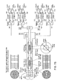
- FIG. 4 which is adapted from FIG. 2 of U.S. Pat. No. 6,377,211, is a simplified block diagram of a mechanism for pointing a parabolic dish antenna, that includes LNBF 31 and that is mounted on a moving vehicle, at a geostationary earth satellite while rotating distal section 32 to keep OMT ports 39 and 41 aligned with the polarization directions of the satellite.
- a Global Positioning System (GPS) receiver 110 mounted on the vehicle receives signals from GPS satellites in a known manner and produces signals that represent vehicle position, the current time (coordinated Universal Time or UPC) and a one-pulse-per-second timing pulse, all of which are applied to a Digital Signal Processor (DSP) 112 .
- GPS Global Positioning System
- the vehicle position information includes latitude, longitude and altitude.
- a vehicle speed sensor 114 produces signals representing the speed of the vehicle, which are applied to DSP 112 .
- DSP 112 also receives signals representing vehicles roll, inclination (pitch) and azimuth angle (yaw) from (an) appropriate sensor(s) 116 mounted on the vehicle.
- One such sensor is the Crossbow Model HDX-AHRS, available from Crossbow Technology, Inc. of San Jose Calif., that senses roll, inclination and azimuth angle, and that includes a three-axis magnetometer to make a true measurement of magnetic heading.
- the azimuth information may be in the form of signals representing vehicle yaw relative to magnetic north; magnetic correction then can be performed in DSP 112 based on the location information from GPS receiver 110 together with stored magnetic declination data.
- GPS receiver 110 , orientation sensor(s) 116 and speed sensor 114 provide DSP 112 with data at an update rate faster than once per second, thereby allowing the antenna pointing system to have a near-real-time response.
- DSP 112 processes the sensor signals relative to the location of the satellite to produce antenna drive or control signals, which are applied to the drive motors of the parabolic dish antenna, including a motor for rotating distal section 32 , to keep LNBF 31 pointed at the satellite and to rotate distal section 32 to keep OMT ports 39 and 41 aligned with the polarization directions of the satellite.
- LNBF 30 can be used for communicating with a satellite that transmits and receives circularly polarized radio waves if slab 42 is kept at a 90 degree angle to slab 44 . This is not the case with LNBF 31 . It would be highly advantageous to have a LNBF, in which the proximal end of the waveguide is coupled to an OMT, and that can be used for communicating both with satellites that transmit and receive linearly polarized radio waves and with satellites that transmit and receive circularly polarized radio waves.
- a waveguide including: (a) a distal section; (b) a medial section; and (c) a proximal section; wherein the distal section and the medial section are configured to rotate relative to each other and to relative to the proximal section; wherein, when the distal section and the medial section are in a first configuration relative to each other and to the proximal section, the waveguide transforms linearly polarized electromagnetic radiation input to a proximal end of the proximal section into linearly polarized electromagnetic radiation output from a distal end of the distal section and transforms linearly polarized electromagnetic radiation input to the distal end of the distal section into linearly polarized electromagnetic radiation output from the proximal end of the proximal section; wherein, when the distal section and the medial section are in a second configuration relative to each other and to the proximal section, the waveguide transforms linearly polarized electromagnetic radiation input to the proximal end of the proximal section
- a back end for an orthogonal mode transducer that includes a port for exchanging signals of a certain polarization, the back end including: (a) a diplexer, for being coupled operationally to the port; (b) a block up-converter; (c) a low noise block; (d) a receive reject filter wherethrough the block up-converter is operationally coupled to the diplexer; and (e) a transmit reject filter, wherethrough the low noise block is opearationally coupled to the diplexer.
- a basic waveguide of the present invention includes three sections: a distal section, a medial section and a proximal section.
- the distal and medial sections are configured to rotate relative to each other and relative to the proximal section.
- the waveguide transforms linearly polarized radiation that is input to the proximal end of the proximal section into linearly polarized electromagnetic radiation (usually but not necessarily polarized in a different direction) that is output from the distal end of the distal section (for example, for transmission to a satellite) and transforms linearly polarized electromagnetic radiation that is input to the distal end of the distal section into linearly polarized electromagnetic radiation (usually but not necessarily polarized in a different direction) that is output from the proximal end of the proximal section (for example for receiving transmissions from a satellite).
- the waveguide transforms linearly polarized radiation that is input to the proximal end of the proximal section into circularly polarized electromagnetic radiation that is output from the distal end of the distal section (for example, for transmission to a satellite) and transforms circularly polarized electromagnetic radiation that is input to the distal end of the distal section into linearly polarized electromagnetic radiation that is output from the proximal end of the proximal section (for example for receiving transmissions from a satellite).
- the distal section and the medial section are rotated differently with respect to each other in the second configuration than in the first configuration.
- the distal and medial sections include respective eight-wavelength polarizers and the proximal section includes a quarter-wavelength polarizer.
- the polarizers include respective dielectric slabs. In other embodiments, the polarizers are quad ridge polarizers.
- the angular orientation of the distal section to the medial section in the second configuration is displaced by 90 degrees from the angular orientation of the distal section to the medial section in the first configuration.
- the scope of the present invention also includes an antenna feed that includes the waveguide of the present invention.
- the antenna feed also includes an orthogonal mode transducer that is operationally coupled to the proximal end of the proximal section of the waveguide.
- the orthogonal mode transducer is fixedly attached to the proximal end of the proximal section of the waveguide.
- the orthogonal mode transducer includes a first port for exchanging vertically polarized signals and a second port for exchanging horizontally polarized signals.
- Each port has a diplexer operationally coupled thereto.
- a block up-converter is operationally coupled to the diplexer via a receive reject filter.
- a low noise block is operationally coupled to the diplexer via a transmit reject filter.
- the scope of the present invention also includes a ground station antenna that includes the antenna feed of the present invention and a mechanism for rotating the distal and medial sections of the waveguide relative to each other and relative to the proximal section of the waveguide to place the waveguide alternately and reversibly in either of its two configurations.
- the scope of the present invention also includes a multi-band antenna feed that includes two waveguides of the present invention, each waveguide for transforming electromagnetic radiation of respective frequency bands.
- One waveguide is nested within the other waveguide.
- the waveguides could have circular cross sections, in which case the inner waveguide is nested concentrically within the outer waveguide.
- the waveguides could have rectangular cross sections.
- the multi-band antenna feed also includes, for each waveguide, a respective orthogonal mode transducer operationally coupled to the proximal end of the proximal section of the waveguide.
- Each orthogonal mode transducer includes a first port for exchanging vertically polarized signals and a second port for exchanging horizontally polarized signals.
- Each port has a diplexer operationally coupled thereto.
- a block up-converter is operationally coupled to the diplexer via a receive reject filter.
- a low noise block is operationally coupled to the diplexer via a transmit reject filter.
- the respective frequency bands of the waveguides could be the C and X-bands, the C and Ku-bands, the C and Ka-bands, the X and Ku-bands, the X and Ka-bands, or the Ku and Ka-bands.
- the scope of the present invention also includes, as an invention in its own right, the kind of back end that is coupled to the orthogonal mode transducer(s) of the antenna feed(s) of the present invention: a diplexer for being coupled operationally to a port of the orthogonal mode transducer, a block up-converter coupled operationally to the diplexer via a receive reject filter, and a low noise block operationally coupled to the diplexer via a transmit reject filter.
- FIGS. 1A and 1B show a prior art parabolic dish antenna
- FIGS. 2A-2D illustrate a prior art LNBF for keeping a moving ground station antenna aligned with a satellite that transmits and received linearly polarized electromagnetic waves
- FIG. 3 illustrates the tapering of the dielectric slab polarizers of the LNBF of FIGS. 2A-2D ;
- FIG. 4 is a simplified block diagram of a prior art mechanism for pointing a moving ground station antenna at a geostationary satellite
- FIGS. 5A-5E illustrate a LNBF of the present invention
- FIG. 6 illustrates the tapered eighth-wavelength dielectric slab polarizers of the LNBF of FIGS. 5A-5E ;
- FIGS. 7A-7C show dual-band antenna feeds of the present invention, each with its two nested waveguides configured for communicating with a satellite that transmits and receives linearly polarized electromagnetic radiation;
- FIG. 8A-8C show dual-band antenna feeds of the present invention, each with its two nested waveguides configured for communicating with a satellite that transmits and receives circularly polarized electromagnetic radiation.
- FIGS. 5A-5E and 6 illustrate such a modified LNBF 131 .
- LNBF 131 is LNBF 31 with distal section 32 of waveguide 50 split into two rotating sections of a waveguide 150 : a rotating distal section 132 and a rotating medial section 134 .
- Dielectric slab 42 is split transversely in half, into two dielectric slabs 142 and 144 , as shown in FIG. 6 . As shown in FIGS.
- FIGS. 5B and 5C are cross sections of LNBF 131 through sections A-A and B-B that correspond to FIG. 2C . As shown in FIGS.
- dielectric slab 44 is shown in phantom behind dielectric slabs 142 and 144 . It can be shown that if dielectric slab 142 is held at the 45 degree counter-clockwise orientation relative to dielectric slab 44 that is shown in FIG.
- dielectric slab 144 is held at the 45 degree clockwise orientation relative to dielectric slab 44 that is shown in FIG. 5E , then circularly polarized transmissions from a satellite that are received at feed horn 48 are transformed to linearly polarized received signals at OMT 36 and linearly polarized transmitted signals at OMT 36 are transformed into circularly polarized transmissions to the satellite at feed horn 48 .
- the ground station antenna in which LNBF 131 is mounted is provided with two motors for rotating distal section 132 and medial section 134 , in place of the single prior art motor for rotating distal section 32 .
- the motors For communicating from a moving platform with a satellite that transmits and receives linearly polarized electromagnetic radiation, the motors rotate distal section 132 and medial section 134 together the way the prior art motor rotates distal section 32 .
- one motor rotates distal section 132 to the orientation shown in FIG. 5D and holds distal section 132 in that orientation, and the other motor rotates medial section 134 to the orientation shown in FIG. 5E and then holds medial section 134 in that orientation.
- FIGS. 7A and 8A show a dual-band antenna feed, of the present invention, that includes two concentrically nested waveguides of the present invention, each with its respective OMT and back end.
- the inner waveguide is for communicating in the Ka-band (17.7 GHz to 31 GHz).
- the outer waveguide is for communicating in the Ku-band (10.7 GHz to 14.5 GHz).
- FIG. 7A shows the two waveguides configured for communicating with a satellite that transmits and receives linearly polarized electromagnetic radiation: distal sections 132 and medial sections 134 of the waveguides rotate together to function as quarter-wavelength polarizers.
- FIG. 8A shows the two waveguides configured for communicating with a satellite that transmits and receives circularly polarized electromagnetic radiation: distal sections 132 and medial sections 134 of the waveguides are fixed in place as separate eighth-wavelength polarizers.
- Each OMT in FIG. 7A is coupled to its own back end for receiving vertically and horizontally polarized signals to transmit from respective Block Up-Converters (BUCs) and for sending received vertically and horizontally polarized signals to respective LNBs.
- the vertical polarization port 152 of the Ku-band OMT is coupled, via a diplexer 154 and a receive reject filter 156 , to the Ku-band vertical polarization BUC 160 , and, via diplexer 154 and a transmit reject filter 158 , to the Ku-band vertical polarization LNB 162 .
- the horizontal polarization port 164 of the Ku-band is coupled, via a diplexer 154 and a receive reject filter 156 , to the Ku-band vertical polarization BUC 160 , and, via diplexer 154 and a transmit reject filter 158 , to the Ku-band vertical polarization LNB 162 .
- OMT is coupled, via a diplexer 166 and a receive reject filter 168 , to the Ku-band horizontal polarization BUC 172 , and, via diplexer 166 and a transmit reject filter 170 , to the Ku-band horizontal polarization LNB 174 .
- the vertical polarization port 176 of the Ka-band OMT is coupled, via a diplexer 178 and a receive reject filter 180 , to the Ka-band vertical polarization BUC 184 , and, via diplexer 178 and a transmit reject filter 182 , to the Ka-band vertical polarization LNB 186 ; and the horizontal polarization port 188 of the Ka-band OMT is coupled, via a diplexer 190 and a receive reject filter 192 , to the Ka-band horizontal polarization BUC 196 , and, via diplexer 190 and a transmit reject filter 194 , to the Ka-band horizontal polarization LNB 198 .
- the diplexers and the filters need to be load-matched in their respective bands. These back ends support simultaneous transmission and reception in both polarizations in both frequency bands.
- the following table shows the XPD of the configuration of FIG. 7A .
- the following table shows the XPD of the configuration of FIG. 8A .
- Waveguides of the present invention that are tuned to other frequency bands can be nested similarly and can be provided with similar, load-matched back ends.
- the following table shows the XPD of a nested waveguide configuration for linear polarization that is similar to the configuration of FIG. 7A but in which the inner waveguide is for the Ka-band and the outer waveguide is for the X-band (7.25 GHz to 8.4 GHz). This nested waveguide configuration is illustrated in FIG. 7B .
- the following table shows the XPD of a nested waveguide configuration for circular polarization that is similar to the configuration of FIG. 8A but in which the inner waveguide is for the Ka-band and the outer waveguide is for the X-band.
- This nested waveguide configuration is illustrated in FIG. 8B .
- the following table shows the XPD of a nested waveguide configuration for linear polarization that is similar to the configuration of FIG. 7A but in which the inner waveguide is for the Ku-band and the outer waveguide is for the C-band (3.4 GHz to 6.725 GHz).
- This nested waveguide configuration is illustrated in FIG. 7C .
- the following table shows the XPD of a nested waveguide configuration for circular polarization that is similar to the configuration of FIG. 8 but in which the inner waveguide is for the Ku-band and the outer waveguide is for the C-band.
- This nested waveguide configuration is illustrated in FIG. 8C .
- the present invention is not limited to only two nested waveguides.
- the following table shows the preferred cross-sectional dimensions of two configurations of four nested waveguides for simultaneous transmission and reception in all four of the bands that are used for satellite communication.
- One configuration uses nested concentric waveguides of circular cross-section.
- the other configuration uses nested waveguides of rectangular cross-section.
- the innermost waveguide is the Ka-band waveguide that is nested inside a Ku-band waveguide.
- the Ku-band waveguide is nested inside an X-band waveguide.
- the X-band waveguide is nested inside a C-band waveguide.
- the Ku-band XPDs configurations of FIGS. 7 and 8 are adequate for separate transmission and reception but not for simultaneous transmission and reception.
- U.S. Ser. No. 12/555,007 points out that the dual quad ridge polarizer of Vezmar, U.S. Pat. No. 6,097,264, gives better XPD than the dielectric slab design described above.
- Using dual quad ridge polarizers in the distal 132 , medial 134 and proximal 34 sections of a Ka waveguide 150 gives XPDs of >35 dB in transmission and >20 dB in reception.
Abstract
Description
| Rx frequency | Tx frequency | XPD in | XPD in | ||
| (GHz) | (GHz) | Rx | Tx | ||
| Ku-band | 10.7-12.75 | 13.75-14.5 | >25 | >30 |
| Ka-band | 17.7-21.2 | 27.5-31 | >20 | >25 |
| Rx frequency | Tx frequency | XPD in | XPD in | ||
| (GHz) | (GHz) | Rx | Tx | ||
| Ku-band | 10.7-12.75 | 13.75-14.5 | >22 | >27 |
| Ka-band | 17.7-21.2 | 27.5-31 | >17 | >22 |
| Rx frequency | Tx frequency | XPD in | XPD in | ||
| (GHz) | (GHz) | Rx | Tx | ||
| Ka-band | 17.7-21.2 | 27.5-31 | >20 | >25 |
| X-band | 7.25-7.75 | 7.9-8.4 | >25 | >30 |
| Rx frequency | Tx frequency | XPD in | XPD in | ||
| (GHz) | (GHz) | Rx | Tx | ||
| Ka-band | 17.7-21.2 | 27.5-31 | >17 | >22 |
| X-band | 7.25-7.75 | 7.9-8.4 | >22 | >27 |
| Rx frequency | Tx frequency | XPD in | XPD in | ||
| (GHz) | (GHz) | Rx | Tx | ||
| Ku-band | 10.7-12.75 | 13.75-14.5 | >25 | >30 |
| C-band | 3.625-4.2 | 5.85-6.425 | >20 | >25 |
| Rx frequency | Tx frequency | XPD in | XPD in | ||
| (GHz) | (GHz) | Rx | Tx | ||
| Ku-band | 10.7-12.75 | 13.75-14.5 | >22 | >27 |
| C-band | 3.625-4.2 | 5.85-6.425 | >17 | >22 |
| Circular cross-section | Rectangular cross section | ||
| Frequency | Inner diameter | Outer diameter | Height | Width |
| band | (mm) | (mm) | (mm) | (mm) |
| Ka | 12.79 | 4.32 | 10.67 | |
| Ku | 12.79 | 26.15 | 9.53 | 19.05 |
| X | 26.15 | 45.62 | 12.62 | 28.50 |
| C | 45.62 | 80.65 | 29.08 | 58.17 |
Claims (17)
Priority Applications (1)
| Application Number | Priority Date | Filing Date | Title |
|---|---|---|---|
| US13/338,286 US8994473B2 (en) | 2010-12-30 | 2011-12-28 | Multi-band feed assembly for linear and circular polarization |
Applications Claiming Priority (2)
| Application Number | Priority Date | Filing Date | Title |
|---|---|---|---|
| US201061428248P | 2010-12-30 | 2010-12-30 | |
| US13/338,286 US8994473B2 (en) | 2010-12-30 | 2011-12-28 | Multi-band feed assembly for linear and circular polarization |
Publications (2)
| Publication Number | Publication Date |
|---|---|
| US20120169557A1 US20120169557A1 (en) | 2012-07-05 |
| US8994473B2 true US8994473B2 (en) | 2015-03-31 |
Family
ID=46380297
Family Applications (1)
| Application Number | Title | Priority Date | Filing Date |
|---|---|---|---|
| US13/338,286 Active 2033-07-09 US8994473B2 (en) | 2010-12-30 | 2011-12-28 | Multi-band feed assembly for linear and circular polarization |
Country Status (1)
| Country | Link |
|---|---|
| US (1) | US8994473B2 (en) |
Cited By (147)
| Publication number | Priority date | Publication date | Assignee | Title |
|---|---|---|---|---|
| CN104752826A (en) * | 2015-03-06 | 2015-07-01 | 江苏麦科讯通信科技有限公司 | Satellite feed source assembly |
| US9608740B2 (en) | 2015-07-15 | 2017-03-28 | At&T Intellectual Property I, L.P. | Method and apparatus for launching a wave mode that mitigates interference |
| US9615269B2 (en) | 2014-10-02 | 2017-04-04 | At&T Intellectual Property I, L.P. | Method and apparatus that provides fault tolerance in a communication network |
| US9628116B2 (en) | 2015-07-14 | 2017-04-18 | At&T Intellectual Property I, L.P. | Apparatus and methods for transmitting wireless signals |
| US9640850B2 (en) | 2015-06-25 | 2017-05-02 | At&T Intellectual Property I, L.P. | Methods and apparatus for inducing a non-fundamental wave mode on a transmission medium |
| US9667317B2 (en) | 2015-06-15 | 2017-05-30 | At&T Intellectual Property I, L.P. | Method and apparatus for providing security using network traffic adjustments |
| US9674711B2 (en) | 2013-11-06 | 2017-06-06 | At&T Intellectual Property I, L.P. | Surface-wave communications and methods thereof |
| US9685992B2 (en) | 2014-10-03 | 2017-06-20 | At&T Intellectual Property I, L.P. | Circuit panel network and methods thereof |
| US9692101B2 (en) | 2014-08-26 | 2017-06-27 | At&T Intellectual Property I, L.P. | Guided wave couplers for coupling electromagnetic waves between a waveguide surface and a surface of a wire |
| US9699785B2 (en) | 2012-12-05 | 2017-07-04 | At&T Intellectual Property I, L.P. | Backhaul link for distributed antenna system |
| US9705610B2 (en) | 2014-10-21 | 2017-07-11 | At&T Intellectual Property I, L.P. | Transmission device with impairment compensation and methods for use therewith |
| US9705561B2 (en) | 2015-04-24 | 2017-07-11 | At&T Intellectual Property I, L.P. | Directional coupling device and methods for use therewith |
| US9722318B2 (en) | 2015-07-14 | 2017-08-01 | At&T Intellectual Property I, L.P. | Method and apparatus for coupling an antenna to a device |
| US9729197B2 (en) | 2015-10-01 | 2017-08-08 | At&T Intellectual Property I, L.P. | Method and apparatus for communicating network management traffic over a network |
| US9735833B2 (en) | 2015-07-31 | 2017-08-15 | At&T Intellectual Property I, L.P. | Method and apparatus for communications management in a neighborhood network |
| US9742521B2 (en) | 2014-11-20 | 2017-08-22 | At&T Intellectual Property I, L.P. | Transmission device with mode division multiplexing and methods for use therewith |
| US9742462B2 (en) | 2014-12-04 | 2017-08-22 | At&T Intellectual Property I, L.P. | Transmission medium and communication interfaces and methods for use therewith |
| US9749053B2 (en) | 2015-07-23 | 2017-08-29 | At&T Intellectual Property I, L.P. | Node device, repeater and methods for use therewith |
| US9748626B2 (en) | 2015-05-14 | 2017-08-29 | At&T Intellectual Property I, L.P. | Plurality of cables having different cross-sectional shapes which are bundled together to form a transmission medium |
| US9749013B2 (en) | 2015-03-17 | 2017-08-29 | At&T Intellectual Property I, L.P. | Method and apparatus for reducing attenuation of electromagnetic waves guided by a transmission medium |
| US9762289B2 (en) | 2014-10-14 | 2017-09-12 | At&T Intellectual Property I, L.P. | Method and apparatus for transmitting or receiving signals in a transportation system |
| US9769020B2 (en) | 2014-10-21 | 2017-09-19 | At&T Intellectual Property I, L.P. | Method and apparatus for responding to events affecting communications in a communication network |
| US9768833B2 (en) | 2014-09-15 | 2017-09-19 | At&T Intellectual Property I, L.P. | Method and apparatus for sensing a condition in a transmission medium of electromagnetic waves |
| US9769128B2 (en) | 2015-09-28 | 2017-09-19 | At&T Intellectual Property I, L.P. | Method and apparatus for encryption of communications over a network |
| US9780834B2 (en) | 2014-10-21 | 2017-10-03 | At&T Intellectual Property I, L.P. | Method and apparatus for transmitting electromagnetic waves |
| US9787412B2 (en) | 2015-06-25 | 2017-10-10 | At&T Intellectual Property I, L.P. | Methods and apparatus for inducing a fundamental wave mode on a transmission medium |
| US9793951B2 (en) | 2015-07-15 | 2017-10-17 | At&T Intellectual Property I, L.P. | Method and apparatus for launching a wave mode that mitigates interference |
| US9793955B2 (en) | 2015-04-24 | 2017-10-17 | At&T Intellectual Property I, Lp | Passive electrical coupling device and methods for use therewith |
| US9793954B2 (en) | 2015-04-28 | 2017-10-17 | At&T Intellectual Property I, L.P. | Magnetic coupling device and methods for use therewith |
| US9800327B2 (en) | 2014-11-20 | 2017-10-24 | At&T Intellectual Property I, L.P. | Apparatus for controlling operations of a communication device and methods thereof |
| US9820146B2 (en) | 2015-06-12 | 2017-11-14 | At&T Intellectual Property I, L.P. | Method and apparatus for authentication and identity management of communicating devices |
| US9838896B1 (en) | 2016-12-09 | 2017-12-05 | At&T Intellectual Property I, L.P. | Method and apparatus for assessing network coverage |
| US9838078B2 (en) | 2015-07-31 | 2017-12-05 | At&T Intellectual Property I, L.P. | Method and apparatus for exchanging communication signals |
| US9847850B2 (en) | 2014-10-14 | 2017-12-19 | At&T Intellectual Property I, L.P. | Method and apparatus for adjusting a mode of communication in a communication network |
| US9847566B2 (en) | 2015-07-14 | 2017-12-19 | At&T Intellectual Property I, L.P. | Method and apparatus for adjusting a field of a signal to mitigate interference |
| US9853342B2 (en) | 2015-07-14 | 2017-12-26 | At&T Intellectual Property I, L.P. | Dielectric transmission medium connector and methods for use therewith |
| US9860075B1 (en) | 2016-08-26 | 2018-01-02 | At&T Intellectual Property I, L.P. | Method and communication node for broadband distribution |
| US9866309B2 (en) | 2015-06-03 | 2018-01-09 | At&T Intellectual Property I, Lp | Host node device and methods for use therewith |
| US9866276B2 (en) | 2014-10-10 | 2018-01-09 | At&T Intellectual Property I, L.P. | Method and apparatus for arranging communication sessions in a communication system |
| US9865911B2 (en) | 2015-06-25 | 2018-01-09 | At&T Intellectual Property I, L.P. | Waveguide system for slot radiating first electromagnetic waves that are combined into a non-fundamental wave mode second electromagnetic wave on a transmission medium |
| US9871558B2 (en) | 2014-10-21 | 2018-01-16 | At&T Intellectual Property I, L.P. | Guided-wave transmission device and methods for use therewith |
| US9871282B2 (en) | 2015-05-14 | 2018-01-16 | At&T Intellectual Property I, L.P. | At least one transmission medium having a dielectric surface that is covered at least in part by a second dielectric |
| US9871283B2 (en) | 2015-07-23 | 2018-01-16 | At&T Intellectual Property I, Lp | Transmission medium having a dielectric core comprised of plural members connected by a ball and socket configuration |
| US9876571B2 (en) | 2015-02-20 | 2018-01-23 | At&T Intellectual Property I, Lp | Guided-wave transmission device with non-fundamental mode propagation and methods for use therewith |
| US9876605B1 (en) | 2016-10-21 | 2018-01-23 | At&T Intellectual Property I, L.P. | Launcher and coupling system to support desired guided wave mode |
| US9876264B2 (en) | 2015-10-02 | 2018-01-23 | At&T Intellectual Property I, Lp | Communication system, guided wave switch and methods for use therewith |
| US9882257B2 (en) | 2015-07-14 | 2018-01-30 | At&T Intellectual Property I, L.P. | Method and apparatus for launching a wave mode that mitigates interference |
| US9887447B2 (en) | 2015-05-14 | 2018-02-06 | At&T Intellectual Property I, L.P. | Transmission medium having multiple cores and methods for use therewith |
| US9893795B1 (en) | 2016-12-07 | 2018-02-13 | At&T Intellectual Property I, Lp | Method and repeater for broadband distribution |
| US9906269B2 (en) | 2014-09-17 | 2018-02-27 | At&T Intellectual Property I, L.P. | Monitoring and mitigating conditions in a communication network |
| US9904535B2 (en) | 2015-09-14 | 2018-02-27 | At&T Intellectual Property I, L.P. | Method and apparatus for distributing software |
| US9912027B2 (en) | 2015-07-23 | 2018-03-06 | At&T Intellectual Property I, L.P. | Method and apparatus for exchanging communication signals |
| US9912382B2 (en) | 2015-06-03 | 2018-03-06 | At&T Intellectual Property I, Lp | Network termination and methods for use therewith |
| US9912033B2 (en) | 2014-10-21 | 2018-03-06 | At&T Intellectual Property I, Lp | Guided wave coupler, coupling module and methods for use therewith |
| US9911020B1 (en) | 2016-12-08 | 2018-03-06 | At&T Intellectual Property I, L.P. | Method and apparatus for tracking via a radio frequency identification device |
| US9913139B2 (en) | 2015-06-09 | 2018-03-06 | At&T Intellectual Property I, L.P. | Signal fingerprinting for authentication of communicating devices |
| US9912419B1 (en) | 2016-08-24 | 2018-03-06 | At&T Intellectual Property I, L.P. | Method and apparatus for managing a fault in a distributed antenna system |
| US9917341B2 (en) | 2015-05-27 | 2018-03-13 | At&T Intellectual Property I, L.P. | Apparatus and method for launching electromagnetic waves and for modifying radial dimensions of the propagating electromagnetic waves |
| US9930668B2 (en) | 2013-05-31 | 2018-03-27 | At&T Intellectual Property I, L.P. | Remote distributed antenna system |
| US9927517B1 (en) | 2016-12-06 | 2018-03-27 | At&T Intellectual Property I, L.P. | Apparatus and methods for sensing rainfall |
| US9939585B1 (en) | 2017-05-26 | 2018-04-10 | Kvh Industries, Inc. | Waveguide device with switchable polarization configurations |
| US9948333B2 (en) | 2015-07-23 | 2018-04-17 | At&T Intellectual Property I, L.P. | Method and apparatus for wireless communications to mitigate interference |
| US9948355B2 (en) | 2014-10-21 | 2018-04-17 | At&T Intellectual Property I, L.P. | Apparatus for providing communication services and methods thereof |
| US9948354B2 (en) | 2015-04-28 | 2018-04-17 | At&T Intellectual Property I, L.P. | Magnetic coupling device with reflective plate and methods for use therewith |
| US9954286B2 (en) | 2014-10-21 | 2018-04-24 | At&T Intellectual Property I, L.P. | Guided-wave transmission device with non-fundamental mode propagation and methods for use therewith |
| US9954287B2 (en) | 2014-11-20 | 2018-04-24 | At&T Intellectual Property I, L.P. | Apparatus for converting wireless signals and electromagnetic waves and methods thereof |
| US9967173B2 (en) | 2015-07-31 | 2018-05-08 | At&T Intellectual Property I, L.P. | Method and apparatus for authentication and identity management of communicating devices |
| US9973940B1 (en) | 2017-02-27 | 2018-05-15 | At&T Intellectual Property I, L.P. | Apparatus and methods for dynamic impedance matching of a guided wave launcher |
| US9991580B2 (en) | 2016-10-21 | 2018-06-05 | At&T Intellectual Property I, L.P. | Launcher and coupling system for guided wave mode cancellation |
| US9998870B1 (en) | 2016-12-08 | 2018-06-12 | At&T Intellectual Property I, L.P. | Method and apparatus for proximity sensing |
| US9999038B2 (en) | 2013-05-31 | 2018-06-12 | At&T Intellectual Property I, L.P. | Remote distributed antenna system |
| US9997819B2 (en) | 2015-06-09 | 2018-06-12 | At&T Intellectual Property I, L.P. | Transmission medium and method for facilitating propagation of electromagnetic waves via a core |
| US10009067B2 (en) | 2014-12-04 | 2018-06-26 | At&T Intellectual Property I, L.P. | Method and apparatus for configuring a communication interface |
| US10009065B2 (en) | 2012-12-05 | 2018-06-26 | At&T Intellectual Property I, L.P. | Backhaul link for distributed antenna system |
| US10009063B2 (en) | 2015-09-16 | 2018-06-26 | At&T Intellectual Property I, L.P. | Method and apparatus for use with a radio distributed antenna system having an out-of-band reference signal |
| US10020844B2 (en) | 2016-12-06 | 2018-07-10 | T&T Intellectual Property I, L.P. | Method and apparatus for broadcast communication via guided waves |
| US10027397B2 (en) | 2016-12-07 | 2018-07-17 | At&T Intellectual Property I, L.P. | Distributed antenna system and methods for use therewith |
| US10027398B2 (en) | 2015-06-11 | 2018-07-17 | At&T Intellectual Property I, Lp | Repeater and methods for use therewith |
| US10033107B2 (en) | 2015-07-14 | 2018-07-24 | At&T Intellectual Property I, L.P. | Method and apparatus for coupling an antenna to a device |
| US10033108B2 (en) | 2015-07-14 | 2018-07-24 | At&T Intellectual Property I, L.P. | Apparatus and methods for generating an electromagnetic wave having a wave mode that mitigates interference |
| US10044409B2 (en) | 2015-07-14 | 2018-08-07 | At&T Intellectual Property I, L.P. | Transmission medium and methods for use therewith |
| US10069535B2 (en) | 2016-12-08 | 2018-09-04 | At&T Intellectual Property I, L.P. | Apparatus and methods for launching electromagnetic waves having a certain electric field structure |
| US10079661B2 (en) | 2015-09-16 | 2018-09-18 | At&T Intellectual Property I, L.P. | Method and apparatus for use with a radio distributed antenna system having a clock reference |
| US10090606B2 (en) | 2015-07-15 | 2018-10-02 | At&T Intellectual Property I, L.P. | Antenna system with dielectric array and methods for use therewith |
| US10090594B2 (en) | 2016-11-23 | 2018-10-02 | At&T Intellectual Property I, L.P. | Antenna system having structural configurations for assembly |
| US10103801B2 (en) | 2015-06-03 | 2018-10-16 | At&T Intellectual Property I, L.P. | Host node device and methods for use therewith |
| US10103422B2 (en) | 2016-12-08 | 2018-10-16 | At&T Intellectual Property I, L.P. | Method and apparatus for mounting network devices |
| US10135146B2 (en) | 2016-10-18 | 2018-11-20 | At&T Intellectual Property I, L.P. | Apparatus and methods for launching guided waves via circuits |
| US10135145B2 (en) | 2016-12-06 | 2018-11-20 | At&T Intellectual Property I, L.P. | Apparatus and methods for generating an electromagnetic wave along a transmission medium |
| US10136434B2 (en) | 2015-09-16 | 2018-11-20 | At&T Intellectual Property I, L.P. | Method and apparatus for use with a radio distributed antenna system having an ultra-wideband control channel |
| US10135147B2 (en) | 2016-10-18 | 2018-11-20 | At&T Intellectual Property I, L.P. | Apparatus and methods for launching guided waves via an antenna |
| US10142086B2 (en) | 2015-06-11 | 2018-11-27 | At&T Intellectual Property I, L.P. | Repeater and methods for use therewith |
| US10139820B2 (en) | 2016-12-07 | 2018-11-27 | At&T Intellectual Property I, L.P. | Method and apparatus for deploying equipment of a communication system |
| US10144036B2 (en) | 2015-01-30 | 2018-12-04 | At&T Intellectual Property I, L.P. | Method and apparatus for mitigating interference affecting a propagation of electromagnetic waves guided by a transmission medium |
| US10148016B2 (en) | 2015-07-14 | 2018-12-04 | At&T Intellectual Property I, L.P. | Apparatus and methods for communicating utilizing an antenna array |
| US10170840B2 (en) | 2015-07-14 | 2019-01-01 | At&T Intellectual Property I, L.P. | Apparatus and methods for sending or receiving electromagnetic signals |
| US10168695B2 (en) | 2016-12-07 | 2019-01-01 | At&T Intellectual Property I, L.P. | Method and apparatus for controlling an unmanned aircraft |
| US10178445B2 (en) | 2016-11-23 | 2019-01-08 | At&T Intellectual Property I, L.P. | Methods, devices, and systems for load balancing between a plurality of waveguides |
| US10205655B2 (en) | 2015-07-14 | 2019-02-12 | At&T Intellectual Property I, L.P. | Apparatus and methods for communicating utilizing an antenna array and multiple communication paths |
| US10224634B2 (en) | 2016-11-03 | 2019-03-05 | At&T Intellectual Property I, L.P. | Methods and apparatus for adjusting an operational characteristic of an antenna |
| US10225025B2 (en) | 2016-11-03 | 2019-03-05 | At&T Intellectual Property I, L.P. | Method and apparatus for detecting a fault in a communication system |
| US10243270B2 (en) | 2016-12-07 | 2019-03-26 | At&T Intellectual Property I, L.P. | Beam adaptive multi-feed dielectric antenna system and methods for use therewith |
| US10243784B2 (en) | 2014-11-20 | 2019-03-26 | At&T Intellectual Property I, L.P. | System for generating topology information and methods thereof |
| US10264586B2 (en) | 2016-12-09 | 2019-04-16 | At&T Mobility Ii Llc | Cloud-based packet controller and methods for use therewith |
| US10291334B2 (en) | 2016-11-03 | 2019-05-14 | At&T Intellectual Property I, L.P. | System for detecting a fault in a communication system |
| US10291311B2 (en) | 2016-09-09 | 2019-05-14 | At&T Intellectual Property I, L.P. | Method and apparatus for mitigating a fault in a distributed antenna system |
| US10298293B2 (en) | 2017-03-13 | 2019-05-21 | At&T Intellectual Property I, L.P. | Apparatus of communication utilizing wireless network devices |
| US10305190B2 (en) | 2016-12-01 | 2019-05-28 | At&T Intellectual Property I, L.P. | Reflecting dielectric antenna system and methods for use therewith |
| US10312567B2 (en) | 2016-10-26 | 2019-06-04 | At&T Intellectual Property I, L.P. | Launcher with planar strip antenna and methods for use therewith |
| US10320586B2 (en) | 2015-07-14 | 2019-06-11 | At&T Intellectual Property I, L.P. | Apparatus and methods for generating non-interfering electromagnetic waves on an insulated transmission medium |
| US10326494B2 (en) | 2016-12-06 | 2019-06-18 | At&T Intellectual Property I, L.P. | Apparatus for measurement de-embedding and methods for use therewith |
| US10326689B2 (en) | 2016-12-08 | 2019-06-18 | At&T Intellectual Property I, L.P. | Method and system for providing alternative communication paths |
| US10340601B2 (en) | 2016-11-23 | 2019-07-02 | At&T Intellectual Property I, L.P. | Multi-antenna system and methods for use therewith |
| US10340603B2 (en) | 2016-11-23 | 2019-07-02 | At&T Intellectual Property I, L.P. | Antenna system having shielded structural configurations for assembly |
| US10340573B2 (en) | 2016-10-26 | 2019-07-02 | At&T Intellectual Property I, L.P. | Launcher with cylindrical coupling device and methods for use therewith |
| US10340983B2 (en) | 2016-12-09 | 2019-07-02 | At&T Intellectual Property I, L.P. | Method and apparatus for surveying remote sites via guided wave communications |
| US10340600B2 (en) | 2016-10-18 | 2019-07-02 | At&T Intellectual Property I, L.P. | Apparatus and methods for launching guided waves via plural waveguide systems |
| US10341142B2 (en) | 2015-07-14 | 2019-07-02 | At&T Intellectual Property I, L.P. | Apparatus and methods for generating non-interfering electromagnetic waves on an uninsulated conductor |
| US10355367B2 (en) | 2015-10-16 | 2019-07-16 | At&T Intellectual Property I, L.P. | Antenna structure for exchanging wireless signals |
| US10361489B2 (en) | 2016-12-01 | 2019-07-23 | At&T Intellectual Property I, L.P. | Dielectric dish antenna system and methods for use therewith |
| US10359749B2 (en) | 2016-12-07 | 2019-07-23 | At&T Intellectual Property I, L.P. | Method and apparatus for utilities management via guided wave communication |
| US10374316B2 (en) | 2016-10-21 | 2019-08-06 | At&T Intellectual Property I, L.P. | System and dielectric antenna with non-uniform dielectric |
| US10382976B2 (en) | 2016-12-06 | 2019-08-13 | At&T Intellectual Property I, L.P. | Method and apparatus for managing wireless communications based on communication paths and network device positions |
| US10389037B2 (en) | 2016-12-08 | 2019-08-20 | At&T Intellectual Property I, L.P. | Apparatus and methods for selecting sections of an antenna array and use therewith |
| US10389029B2 (en) | 2016-12-07 | 2019-08-20 | At&T Intellectual Property I, L.P. | Multi-feed dielectric antenna system with core selection and methods for use therewith |
| US10411356B2 (en) | 2016-12-08 | 2019-09-10 | At&T Intellectual Property I, L.P. | Apparatus and methods for selectively targeting communication devices with an antenna array |
| US10439675B2 (en) | 2016-12-06 | 2019-10-08 | At&T Intellectual Property I, L.P. | Method and apparatus for repeating guided wave communication signals |
| US10446936B2 (en) | 2016-12-07 | 2019-10-15 | At&T Intellectual Property I, L.P. | Multi-feed dielectric antenna system and methods for use therewith |
| US10498044B2 (en) | 2016-11-03 | 2019-12-03 | At&T Intellectual Property I, L.P. | Apparatus for configuring a surface of an antenna |
| US10530505B2 (en) | 2016-12-08 | 2020-01-07 | At&T Intellectual Property I, L.P. | Apparatus and methods for launching electromagnetic waves along a transmission medium |
| US10535928B2 (en) | 2016-11-23 | 2020-01-14 | At&T Intellectual Property I, L.P. | Antenna system and methods for use therewith |
| US10547348B2 (en) | 2016-12-07 | 2020-01-28 | At&T Intellectual Property I, L.P. | Method and apparatus for switching transmission mediums in a communication system |
| US10601494B2 (en) | 2016-12-08 | 2020-03-24 | At&T Intellectual Property I, L.P. | Dual-band communication device and method for use therewith |
| US10637149B2 (en) | 2016-12-06 | 2020-04-28 | At&T Intellectual Property I, L.P. | Injection molded dielectric antenna and methods for use therewith |
| US10650940B2 (en) | 2015-05-15 | 2020-05-12 | At&T Intellectual Property I, L.P. | Transmission medium having a conductive material and methods for use therewith |
| US10665942B2 (en) | 2015-10-16 | 2020-05-26 | At&T Intellectual Property I, L.P. | Method and apparatus for adjusting wireless communications |
| US10694379B2 (en) | 2016-12-06 | 2020-06-23 | At&T Intellectual Property I, L.P. | Waveguide system with device-based authentication and methods for use therewith |
| US10727599B2 (en) | 2016-12-06 | 2020-07-28 | At&T Intellectual Property I, L.P. | Launcher with slot antenna and methods for use therewith |
| US10755542B2 (en) | 2016-12-06 | 2020-08-25 | At&T Intellectual Property I, L.P. | Method and apparatus for surveillance via guided wave communication |
| US10777873B2 (en) | 2016-12-08 | 2020-09-15 | At&T Intellectual Property I, L.P. | Method and apparatus for mounting network devices |
| US10797781B2 (en) | 2015-06-03 | 2020-10-06 | At&T Intellectual Property I, L.P. | Client node device and methods for use therewith |
| US10811767B2 (en) | 2016-10-21 | 2020-10-20 | At&T Intellectual Property I, L.P. | System and dielectric antenna with convex dielectric radome |
| US10819035B2 (en) | 2016-12-06 | 2020-10-27 | At&T Intellectual Property I, L.P. | Launcher with helical antenna and methods for use therewith |
| US10916969B2 (en) | 2016-12-08 | 2021-02-09 | At&T Intellectual Property I, L.P. | Method and apparatus for providing power using an inductive coupling |
| US10938108B2 (en) | 2016-12-08 | 2021-03-02 | At&T Intellectual Property I, L.P. | Frequency selective multi-feed dielectric antenna system and methods for use therewith |
| US11032819B2 (en) | 2016-09-15 | 2021-06-08 | At&T Intellectual Property I, L.P. | Method and apparatus for use with a radio distributed antenna system having a control channel reference signal |
| US11031682B2 (en) * | 2017-12-14 | 2021-06-08 | Waymo Llc | Adaptive polarimetric radar architecture for autonomous driving |
Families Citing this family (10)
| Publication number | Priority date | Publication date | Assignee | Title |
|---|---|---|---|---|
| CN103296487B (en) * | 2013-05-23 | 2015-04-15 | 京信通信技术(广州)有限公司 | Multi-polarization antenna system and polarization conversion network for multi-polarization antenna system |
| KR101444659B1 (en) * | 2013-10-04 | 2014-09-24 | 국방과학연구소 | ANTENNA SYSTEM FOR simultaneous Triple-band Satellite Communication |
| FR3013909B1 (en) * | 2013-11-28 | 2016-01-01 | Thales Sa | CORNET, ELEMENTARY ANTENNA, ANTENNA STRUCTURE AND TELECOMMUNICATION METHOD THEREOF |
| US9490862B2 (en) | 2014-02-18 | 2016-11-08 | Raytheon Company | Reflective-type antenna band and polarization selectable transceiver using a rotatable quarter-wave plate |
| US10777898B2 (en) * | 2015-09-11 | 2020-09-15 | Antenna Research Associates | Dual polarized dual band full duplex capable horn feed antenna |
| US10297920B2 (en) * | 2017-02-16 | 2019-05-21 | Lockheed Martin Corporation | Compact dual circular polarization multi-band waveguide feed network |
| US10320080B2 (en) * | 2017-07-06 | 2019-06-11 | Raytheon Company | Tri-band feed assembly systems and methods |
| US10615472B2 (en) | 2018-03-08 | 2020-04-07 | Raytheon Company | Feed polarizer step twist switch |
| CN113178706A (en) * | 2021-04-19 | 2021-07-27 | 北京邮电大学 | Polar modulation antenna and communication device |
| CN114204268B (en) * | 2021-11-30 | 2022-09-02 | 中国电子科技集团公司第五十四研究所 | C/Ku dual-frequency shared circularly polarized coaxial feed source network |
Citations (6)
| Publication number | Priority date | Publication date | Assignee | Title |
|---|---|---|---|---|
| US3215957A (en) * | 1962-03-05 | 1965-11-02 | Bendix Corp | Variable polarization for microwaves |
| US5903549A (en) * | 1997-02-21 | 1999-05-11 | Hughes Electronics Corporation | Ground based beam forming utilizing synchronized code division multiplexing |
| US6329957B1 (en) | 1998-10-30 | 2001-12-11 | Austin Information Systems, Inc. | Method and apparatus for transmitting and receiving multiple frequency bands simultaneously |
| US6377211B1 (en) | 2000-12-13 | 2002-04-23 | Lockheed Martin Corporation | Apparatus and method for pointing a directional device from a moving vehicle toward a spacecraft |
| US20110057849A1 (en) | 2009-09-08 | 2011-03-10 | Orbit Communication Ltd. | Dynamic polarization adjustment for a ground station antenna |
| US8089415B1 (en) | 2008-09-23 | 2012-01-03 | Rockwell Collins, Inc. | Multiband radar feed system and method |
-
2011
- 2011-12-28 US US13/338,286 patent/US8994473B2/en active Active
Patent Citations (6)
| Publication number | Priority date | Publication date | Assignee | Title |
|---|---|---|---|---|
| US3215957A (en) * | 1962-03-05 | 1965-11-02 | Bendix Corp | Variable polarization for microwaves |
| US5903549A (en) * | 1997-02-21 | 1999-05-11 | Hughes Electronics Corporation | Ground based beam forming utilizing synchronized code division multiplexing |
| US6329957B1 (en) | 1998-10-30 | 2001-12-11 | Austin Information Systems, Inc. | Method and apparatus for transmitting and receiving multiple frequency bands simultaneously |
| US6377211B1 (en) | 2000-12-13 | 2002-04-23 | Lockheed Martin Corporation | Apparatus and method for pointing a directional device from a moving vehicle toward a spacecraft |
| US8089415B1 (en) | 2008-09-23 | 2012-01-03 | Rockwell Collins, Inc. | Multiband radar feed system and method |
| US20110057849A1 (en) | 2009-09-08 | 2011-03-10 | Orbit Communication Ltd. | Dynamic polarization adjustment for a ground station antenna |
Cited By (174)
| Publication number | Priority date | Publication date | Assignee | Title |
|---|---|---|---|---|
| US9788326B2 (en) | 2012-12-05 | 2017-10-10 | At&T Intellectual Property I, L.P. | Backhaul link for distributed antenna system |
| US10194437B2 (en) | 2012-12-05 | 2019-01-29 | At&T Intellectual Property I, L.P. | Backhaul link for distributed antenna system |
| US10009065B2 (en) | 2012-12-05 | 2018-06-26 | At&T Intellectual Property I, L.P. | Backhaul link for distributed antenna system |
| US9699785B2 (en) | 2012-12-05 | 2017-07-04 | At&T Intellectual Property I, L.P. | Backhaul link for distributed antenna system |
| US10051630B2 (en) | 2013-05-31 | 2018-08-14 | At&T Intellectual Property I, L.P. | Remote distributed antenna system |
| US10091787B2 (en) | 2013-05-31 | 2018-10-02 | At&T Intellectual Property I, L.P. | Remote distributed antenna system |
| US9930668B2 (en) | 2013-05-31 | 2018-03-27 | At&T Intellectual Property I, L.P. | Remote distributed antenna system |
| US9999038B2 (en) | 2013-05-31 | 2018-06-12 | At&T Intellectual Property I, L.P. | Remote distributed antenna system |
| US9674711B2 (en) | 2013-11-06 | 2017-06-06 | At&T Intellectual Property I, L.P. | Surface-wave communications and methods thereof |
| US9692101B2 (en) | 2014-08-26 | 2017-06-27 | At&T Intellectual Property I, L.P. | Guided wave couplers for coupling electromagnetic waves between a waveguide surface and a surface of a wire |
| US10096881B2 (en) | 2014-08-26 | 2018-10-09 | At&T Intellectual Property I, L.P. | Guided wave couplers for coupling electromagnetic waves to an outer surface of a transmission medium |
| US9768833B2 (en) | 2014-09-15 | 2017-09-19 | At&T Intellectual Property I, L.P. | Method and apparatus for sensing a condition in a transmission medium of electromagnetic waves |
| US9906269B2 (en) | 2014-09-17 | 2018-02-27 | At&T Intellectual Property I, L.P. | Monitoring and mitigating conditions in a communication network |
| US10063280B2 (en) | 2014-09-17 | 2018-08-28 | At&T Intellectual Property I, L.P. | Monitoring and mitigating conditions in a communication network |
| US9973416B2 (en) | 2014-10-02 | 2018-05-15 | At&T Intellectual Property I, L.P. | Method and apparatus that provides fault tolerance in a communication network |
| US9998932B2 (en) | 2014-10-02 | 2018-06-12 | At&T Intellectual Property I, L.P. | Method and apparatus that provides fault tolerance in a communication network |
| US9615269B2 (en) | 2014-10-02 | 2017-04-04 | At&T Intellectual Property I, L.P. | Method and apparatus that provides fault tolerance in a communication network |
| US9685992B2 (en) | 2014-10-03 | 2017-06-20 | At&T Intellectual Property I, L.P. | Circuit panel network and methods thereof |
| US9866276B2 (en) | 2014-10-10 | 2018-01-09 | At&T Intellectual Property I, L.P. | Method and apparatus for arranging communication sessions in a communication system |
| US9762289B2 (en) | 2014-10-14 | 2017-09-12 | At&T Intellectual Property I, L.P. | Method and apparatus for transmitting or receiving signals in a transportation system |
| US9973299B2 (en) | 2014-10-14 | 2018-05-15 | At&T Intellectual Property I, L.P. | Method and apparatus for adjusting a mode of communication in a communication network |
| US9847850B2 (en) | 2014-10-14 | 2017-12-19 | At&T Intellectual Property I, L.P. | Method and apparatus for adjusting a mode of communication in a communication network |
| US9705610B2 (en) | 2014-10-21 | 2017-07-11 | At&T Intellectual Property I, L.P. | Transmission device with impairment compensation and methods for use therewith |
| US9960808B2 (en) | 2014-10-21 | 2018-05-01 | At&T Intellectual Property I, L.P. | Guided-wave transmission device and methods for use therewith |
| US9871558B2 (en) | 2014-10-21 | 2018-01-16 | At&T Intellectual Property I, L.P. | Guided-wave transmission device and methods for use therewith |
| US9780834B2 (en) | 2014-10-21 | 2017-10-03 | At&T Intellectual Property I, L.P. | Method and apparatus for transmitting electromagnetic waves |
| US9954286B2 (en) | 2014-10-21 | 2018-04-24 | At&T Intellectual Property I, L.P. | Guided-wave transmission device with non-fundamental mode propagation and methods for use therewith |
| US9876587B2 (en) | 2014-10-21 | 2018-01-23 | At&T Intellectual Property I, L.P. | Transmission device with impairment compensation and methods for use therewith |
| US9948355B2 (en) | 2014-10-21 | 2018-04-17 | At&T Intellectual Property I, L.P. | Apparatus for providing communication services and methods thereof |
| US9769020B2 (en) | 2014-10-21 | 2017-09-19 | At&T Intellectual Property I, L.P. | Method and apparatus for responding to events affecting communications in a communication network |
| US9912033B2 (en) | 2014-10-21 | 2018-03-06 | At&T Intellectual Property I, Lp | Guided wave coupler, coupling module and methods for use therewith |
| US9800327B2 (en) | 2014-11-20 | 2017-10-24 | At&T Intellectual Property I, L.P. | Apparatus for controlling operations of a communication device and methods thereof |
| US9742521B2 (en) | 2014-11-20 | 2017-08-22 | At&T Intellectual Property I, L.P. | Transmission device with mode division multiplexing and methods for use therewith |
| US10243784B2 (en) | 2014-11-20 | 2019-03-26 | At&T Intellectual Property I, L.P. | System for generating topology information and methods thereof |
| US9954287B2 (en) | 2014-11-20 | 2018-04-24 | At&T Intellectual Property I, L.P. | Apparatus for converting wireless signals and electromagnetic waves and methods thereof |
| US9749083B2 (en) | 2014-11-20 | 2017-08-29 | At&T Intellectual Property I, L.P. | Transmission device with mode division multiplexing and methods for use therewith |
| US10009067B2 (en) | 2014-12-04 | 2018-06-26 | At&T Intellectual Property I, L.P. | Method and apparatus for configuring a communication interface |
| US9742462B2 (en) | 2014-12-04 | 2017-08-22 | At&T Intellectual Property I, L.P. | Transmission medium and communication interfaces and methods for use therewith |
| US10144036B2 (en) | 2015-01-30 | 2018-12-04 | At&T Intellectual Property I, L.P. | Method and apparatus for mitigating interference affecting a propagation of electromagnetic waves guided by a transmission medium |
| US9876571B2 (en) | 2015-02-20 | 2018-01-23 | At&T Intellectual Property I, Lp | Guided-wave transmission device with non-fundamental mode propagation and methods for use therewith |
| US9876570B2 (en) | 2015-02-20 | 2018-01-23 | At&T Intellectual Property I, Lp | Guided-wave transmission device with non-fundamental mode propagation and methods for use therewith |
| CN104752826A (en) * | 2015-03-06 | 2015-07-01 | 江苏麦科讯通信科技有限公司 | Satellite feed source assembly |
| US9749013B2 (en) | 2015-03-17 | 2017-08-29 | At&T Intellectual Property I, L.P. | Method and apparatus for reducing attenuation of electromagnetic waves guided by a transmission medium |
| US9705561B2 (en) | 2015-04-24 | 2017-07-11 | At&T Intellectual Property I, L.P. | Directional coupling device and methods for use therewith |
| US9831912B2 (en) | 2015-04-24 | 2017-11-28 | At&T Intellectual Property I, Lp | Directional coupling device and methods for use therewith |
| US9793955B2 (en) | 2015-04-24 | 2017-10-17 | At&T Intellectual Property I, Lp | Passive electrical coupling device and methods for use therewith |
| US10224981B2 (en) | 2015-04-24 | 2019-03-05 | At&T Intellectual Property I, Lp | Passive electrical coupling device and methods for use therewith |
| US9793954B2 (en) | 2015-04-28 | 2017-10-17 | At&T Intellectual Property I, L.P. | Magnetic coupling device and methods for use therewith |
| US9948354B2 (en) | 2015-04-28 | 2018-04-17 | At&T Intellectual Property I, L.P. | Magnetic coupling device with reflective plate and methods for use therewith |
| US9887447B2 (en) | 2015-05-14 | 2018-02-06 | At&T Intellectual Property I, L.P. | Transmission medium having multiple cores and methods for use therewith |
| US9871282B2 (en) | 2015-05-14 | 2018-01-16 | At&T Intellectual Property I, L.P. | At least one transmission medium having a dielectric surface that is covered at least in part by a second dielectric |
| US9748626B2 (en) | 2015-05-14 | 2017-08-29 | At&T Intellectual Property I, L.P. | Plurality of cables having different cross-sectional shapes which are bundled together to form a transmission medium |
| US10650940B2 (en) | 2015-05-15 | 2020-05-12 | At&T Intellectual Property I, L.P. | Transmission medium having a conductive material and methods for use therewith |
| US9917341B2 (en) | 2015-05-27 | 2018-03-13 | At&T Intellectual Property I, L.P. | Apparatus and method for launching electromagnetic waves and for modifying radial dimensions of the propagating electromagnetic waves |
| US10797781B2 (en) | 2015-06-03 | 2020-10-06 | At&T Intellectual Property I, L.P. | Client node device and methods for use therewith |
| US10103801B2 (en) | 2015-06-03 | 2018-10-16 | At&T Intellectual Property I, L.P. | Host node device and methods for use therewith |
| US10812174B2 (en) | 2015-06-03 | 2020-10-20 | At&T Intellectual Property I, L.P. | Client node device and methods for use therewith |
| US9935703B2 (en) | 2015-06-03 | 2018-04-03 | At&T Intellectual Property I, L.P. | Host node device and methods for use therewith |
| US10050697B2 (en) | 2015-06-03 | 2018-08-14 | At&T Intellectual Property I, L.P. | Host node device and methods for use therewith |
| US9912382B2 (en) | 2015-06-03 | 2018-03-06 | At&T Intellectual Property I, Lp | Network termination and methods for use therewith |
| US9967002B2 (en) | 2015-06-03 | 2018-05-08 | At&T Intellectual I, Lp | Network termination and methods for use therewith |
| US9866309B2 (en) | 2015-06-03 | 2018-01-09 | At&T Intellectual Property I, Lp | Host node device and methods for use therewith |
| US9912381B2 (en) | 2015-06-03 | 2018-03-06 | At&T Intellectual Property I, Lp | Network termination and methods for use therewith |
| US9913139B2 (en) | 2015-06-09 | 2018-03-06 | At&T Intellectual Property I, L.P. | Signal fingerprinting for authentication of communicating devices |
| US9997819B2 (en) | 2015-06-09 | 2018-06-12 | At&T Intellectual Property I, L.P. | Transmission medium and method for facilitating propagation of electromagnetic waves via a core |
| US10142010B2 (en) | 2015-06-11 | 2018-11-27 | At&T Intellectual Property I, L.P. | Repeater and methods for use therewith |
| US10027398B2 (en) | 2015-06-11 | 2018-07-17 | At&T Intellectual Property I, Lp | Repeater and methods for use therewith |
| US10142086B2 (en) | 2015-06-11 | 2018-11-27 | At&T Intellectual Property I, L.P. | Repeater and methods for use therewith |
| US9820146B2 (en) | 2015-06-12 | 2017-11-14 | At&T Intellectual Property I, L.P. | Method and apparatus for authentication and identity management of communicating devices |
| US9667317B2 (en) | 2015-06-15 | 2017-05-30 | At&T Intellectual Property I, L.P. | Method and apparatus for providing security using network traffic adjustments |
| US9640850B2 (en) | 2015-06-25 | 2017-05-02 | At&T Intellectual Property I, L.P. | Methods and apparatus for inducing a non-fundamental wave mode on a transmission medium |
| US9882657B2 (en) | 2015-06-25 | 2018-01-30 | At&T Intellectual Property I, L.P. | Methods and apparatus for inducing a fundamental wave mode on a transmission medium |
| US9865911B2 (en) | 2015-06-25 | 2018-01-09 | At&T Intellectual Property I, L.P. | Waveguide system for slot radiating first electromagnetic waves that are combined into a non-fundamental wave mode second electromagnetic wave on a transmission medium |
| US10069185B2 (en) | 2015-06-25 | 2018-09-04 | At&T Intellectual Property I, L.P. | Methods and apparatus for inducing a non-fundamental wave mode on a transmission medium |
| US9787412B2 (en) | 2015-06-25 | 2017-10-10 | At&T Intellectual Property I, L.P. | Methods and apparatus for inducing a fundamental wave mode on a transmission medium |
| US10170840B2 (en) | 2015-07-14 | 2019-01-01 | At&T Intellectual Property I, L.P. | Apparatus and methods for sending or receiving electromagnetic signals |
| US9722318B2 (en) | 2015-07-14 | 2017-08-01 | At&T Intellectual Property I, L.P. | Method and apparatus for coupling an antenna to a device |
| US10320586B2 (en) | 2015-07-14 | 2019-06-11 | At&T Intellectual Property I, L.P. | Apparatus and methods for generating non-interfering electromagnetic waves on an insulated transmission medium |
| US10148016B2 (en) | 2015-07-14 | 2018-12-04 | At&T Intellectual Property I, L.P. | Apparatus and methods for communicating utilizing an antenna array |
| US10033107B2 (en) | 2015-07-14 | 2018-07-24 | At&T Intellectual Property I, L.P. | Method and apparatus for coupling an antenna to a device |
| US9628116B2 (en) | 2015-07-14 | 2017-04-18 | At&T Intellectual Property I, L.P. | Apparatus and methods for transmitting wireless signals |
| US10205655B2 (en) | 2015-07-14 | 2019-02-12 | At&T Intellectual Property I, L.P. | Apparatus and methods for communicating utilizing an antenna array and multiple communication paths |
| US10033108B2 (en) | 2015-07-14 | 2018-07-24 | At&T Intellectual Property I, L.P. | Apparatus and methods for generating an electromagnetic wave having a wave mode that mitigates interference |
| US10341142B2 (en) | 2015-07-14 | 2019-07-02 | At&T Intellectual Property I, L.P. | Apparatus and methods for generating non-interfering electromagnetic waves on an uninsulated conductor |
| US10044409B2 (en) | 2015-07-14 | 2018-08-07 | At&T Intellectual Property I, L.P. | Transmission medium and methods for use therewith |
| US9853342B2 (en) | 2015-07-14 | 2017-12-26 | At&T Intellectual Property I, L.P. | Dielectric transmission medium connector and methods for use therewith |
| US9929755B2 (en) | 2015-07-14 | 2018-03-27 | At&T Intellectual Property I, L.P. | Method and apparatus for coupling an antenna to a device |
| US9847566B2 (en) | 2015-07-14 | 2017-12-19 | At&T Intellectual Property I, L.P. | Method and apparatus for adjusting a field of a signal to mitigate interference |
| US9882257B2 (en) | 2015-07-14 | 2018-01-30 | At&T Intellectual Property I, L.P. | Method and apparatus for launching a wave mode that mitigates interference |
| US9793951B2 (en) | 2015-07-15 | 2017-10-17 | At&T Intellectual Property I, L.P. | Method and apparatus for launching a wave mode that mitigates interference |
| US9608740B2 (en) | 2015-07-15 | 2017-03-28 | At&T Intellectual Property I, L.P. | Method and apparatus for launching a wave mode that mitigates interference |
| US10090606B2 (en) | 2015-07-15 | 2018-10-02 | At&T Intellectual Property I, L.P. | Antenna system with dielectric array and methods for use therewith |
| US9948333B2 (en) | 2015-07-23 | 2018-04-17 | At&T Intellectual Property I, L.P. | Method and apparatus for wireless communications to mitigate interference |
| US10074886B2 (en) | 2015-07-23 | 2018-09-11 | At&T Intellectual Property I, L.P. | Dielectric transmission medium comprising a plurality of rigid dielectric members coupled together in a ball and socket configuration |
| US9806818B2 (en) | 2015-07-23 | 2017-10-31 | At&T Intellectual Property I, Lp | Node device, repeater and methods for use therewith |
| US9871283B2 (en) | 2015-07-23 | 2018-01-16 | At&T Intellectual Property I, Lp | Transmission medium having a dielectric core comprised of plural members connected by a ball and socket configuration |
| US9749053B2 (en) | 2015-07-23 | 2017-08-29 | At&T Intellectual Property I, L.P. | Node device, repeater and methods for use therewith |
| US9912027B2 (en) | 2015-07-23 | 2018-03-06 | At&T Intellectual Property I, L.P. | Method and apparatus for exchanging communication signals |
| US9838078B2 (en) | 2015-07-31 | 2017-12-05 | At&T Intellectual Property I, L.P. | Method and apparatus for exchanging communication signals |
| US9967173B2 (en) | 2015-07-31 | 2018-05-08 | At&T Intellectual Property I, L.P. | Method and apparatus for authentication and identity management of communicating devices |
| US9735833B2 (en) | 2015-07-31 | 2017-08-15 | At&T Intellectual Property I, L.P. | Method and apparatus for communications management in a neighborhood network |
| US9904535B2 (en) | 2015-09-14 | 2018-02-27 | At&T Intellectual Property I, L.P. | Method and apparatus for distributing software |
| US10136434B2 (en) | 2015-09-16 | 2018-11-20 | At&T Intellectual Property I, L.P. | Method and apparatus for use with a radio distributed antenna system having an ultra-wideband control channel |
| US10009063B2 (en) | 2015-09-16 | 2018-06-26 | At&T Intellectual Property I, L.P. | Method and apparatus for use with a radio distributed antenna system having an out-of-band reference signal |
| US10079661B2 (en) | 2015-09-16 | 2018-09-18 | At&T Intellectual Property I, L.P. | Method and apparatus for use with a radio distributed antenna system having a clock reference |
| US9769128B2 (en) | 2015-09-28 | 2017-09-19 | At&T Intellectual Property I, L.P. | Method and apparatus for encryption of communications over a network |
| US9729197B2 (en) | 2015-10-01 | 2017-08-08 | At&T Intellectual Property I, L.P. | Method and apparatus for communicating network management traffic over a network |
| US9876264B2 (en) | 2015-10-02 | 2018-01-23 | At&T Intellectual Property I, Lp | Communication system, guided wave switch and methods for use therewith |
| US10355367B2 (en) | 2015-10-16 | 2019-07-16 | At&T Intellectual Property I, L.P. | Antenna structure for exchanging wireless signals |
| US10665942B2 (en) | 2015-10-16 | 2020-05-26 | At&T Intellectual Property I, L.P. | Method and apparatus for adjusting wireless communications |
| US9912419B1 (en) | 2016-08-24 | 2018-03-06 | At&T Intellectual Property I, L.P. | Method and apparatus for managing a fault in a distributed antenna system |
| US9860075B1 (en) | 2016-08-26 | 2018-01-02 | At&T Intellectual Property I, L.P. | Method and communication node for broadband distribution |
| US10291311B2 (en) | 2016-09-09 | 2019-05-14 | At&T Intellectual Property I, L.P. | Method and apparatus for mitigating a fault in a distributed antenna system |
| US11032819B2 (en) | 2016-09-15 | 2021-06-08 | At&T Intellectual Property I, L.P. | Method and apparatus for use with a radio distributed antenna system having a control channel reference signal |
| US10135146B2 (en) | 2016-10-18 | 2018-11-20 | At&T Intellectual Property I, L.P. | Apparatus and methods for launching guided waves via circuits |
| US10135147B2 (en) | 2016-10-18 | 2018-11-20 | At&T Intellectual Property I, L.P. | Apparatus and methods for launching guided waves via an antenna |
| US10340600B2 (en) | 2016-10-18 | 2019-07-02 | At&T Intellectual Property I, L.P. | Apparatus and methods for launching guided waves via plural waveguide systems |
| US9991580B2 (en) | 2016-10-21 | 2018-06-05 | At&T Intellectual Property I, L.P. | Launcher and coupling system for guided wave mode cancellation |
| US9876605B1 (en) | 2016-10-21 | 2018-01-23 | At&T Intellectual Property I, L.P. | Launcher and coupling system to support desired guided wave mode |
| US10374316B2 (en) | 2016-10-21 | 2019-08-06 | At&T Intellectual Property I, L.P. | System and dielectric antenna with non-uniform dielectric |
| US10811767B2 (en) | 2016-10-21 | 2020-10-20 | At&T Intellectual Property I, L.P. | System and dielectric antenna with convex dielectric radome |
| US10312567B2 (en) | 2016-10-26 | 2019-06-04 | At&T Intellectual Property I, L.P. | Launcher with planar strip antenna and methods for use therewith |
| US10340573B2 (en) | 2016-10-26 | 2019-07-02 | At&T Intellectual Property I, L.P. | Launcher with cylindrical coupling device and methods for use therewith |
| US10224634B2 (en) | 2016-11-03 | 2019-03-05 | At&T Intellectual Property I, L.P. | Methods and apparatus for adjusting an operational characteristic of an antenna |
| US10225025B2 (en) | 2016-11-03 | 2019-03-05 | At&T Intellectual Property I, L.P. | Method and apparatus for detecting a fault in a communication system |
| US10498044B2 (en) | 2016-11-03 | 2019-12-03 | At&T Intellectual Property I, L.P. | Apparatus for configuring a surface of an antenna |
| US10291334B2 (en) | 2016-11-03 | 2019-05-14 | At&T Intellectual Property I, L.P. | System for detecting a fault in a communication system |
| US10340601B2 (en) | 2016-11-23 | 2019-07-02 | At&T Intellectual Property I, L.P. | Multi-antenna system and methods for use therewith |
| US10178445B2 (en) | 2016-11-23 | 2019-01-08 | At&T Intellectual Property I, L.P. | Methods, devices, and systems for load balancing between a plurality of waveguides |
| US10090594B2 (en) | 2016-11-23 | 2018-10-02 | At&T Intellectual Property I, L.P. | Antenna system having structural configurations for assembly |
| US10535928B2 (en) | 2016-11-23 | 2020-01-14 | At&T Intellectual Property I, L.P. | Antenna system and methods for use therewith |
| US10340603B2 (en) | 2016-11-23 | 2019-07-02 | At&T Intellectual Property I, L.P. | Antenna system having shielded structural configurations for assembly |
| US10361489B2 (en) | 2016-12-01 | 2019-07-23 | At&T Intellectual Property I, L.P. | Dielectric dish antenna system and methods for use therewith |
| US10305190B2 (en) | 2016-12-01 | 2019-05-28 | At&T Intellectual Property I, L.P. | Reflecting dielectric antenna system and methods for use therewith |
| US10727599B2 (en) | 2016-12-06 | 2020-07-28 | At&T Intellectual Property I, L.P. | Launcher with slot antenna and methods for use therewith |
| US10382976B2 (en) | 2016-12-06 | 2019-08-13 | At&T Intellectual Property I, L.P. | Method and apparatus for managing wireless communications based on communication paths and network device positions |
| US10020844B2 (en) | 2016-12-06 | 2018-07-10 | T&T Intellectual Property I, L.P. | Method and apparatus for broadcast communication via guided waves |
| US9927517B1 (en) | 2016-12-06 | 2018-03-27 | At&T Intellectual Property I, L.P. | Apparatus and methods for sensing rainfall |
| US10637149B2 (en) | 2016-12-06 | 2020-04-28 | At&T Intellectual Property I, L.P. | Injection molded dielectric antenna and methods for use therewith |
| US10439675B2 (en) | 2016-12-06 | 2019-10-08 | At&T Intellectual Property I, L.P. | Method and apparatus for repeating guided wave communication signals |
| US10819035B2 (en) | 2016-12-06 | 2020-10-27 | At&T Intellectual Property I, L.P. | Launcher with helical antenna and methods for use therewith |
| US10755542B2 (en) | 2016-12-06 | 2020-08-25 | At&T Intellectual Property I, L.P. | Method and apparatus for surveillance via guided wave communication |
| US10694379B2 (en) | 2016-12-06 | 2020-06-23 | At&T Intellectual Property I, L.P. | Waveguide system with device-based authentication and methods for use therewith |
| US10135145B2 (en) | 2016-12-06 | 2018-11-20 | At&T Intellectual Property I, L.P. | Apparatus and methods for generating an electromagnetic wave along a transmission medium |
| US10326494B2 (en) | 2016-12-06 | 2019-06-18 | At&T Intellectual Property I, L.P. | Apparatus for measurement de-embedding and methods for use therewith |
| US10359749B2 (en) | 2016-12-07 | 2019-07-23 | At&T Intellectual Property I, L.P. | Method and apparatus for utilities management via guided wave communication |
| US10168695B2 (en) | 2016-12-07 | 2019-01-01 | At&T Intellectual Property I, L.P. | Method and apparatus for controlling an unmanned aircraft |
| US9893795B1 (en) | 2016-12-07 | 2018-02-13 | At&T Intellectual Property I, Lp | Method and repeater for broadband distribution |
| US10139820B2 (en) | 2016-12-07 | 2018-11-27 | At&T Intellectual Property I, L.P. | Method and apparatus for deploying equipment of a communication system |
| US10389029B2 (en) | 2016-12-07 | 2019-08-20 | At&T Intellectual Property I, L.P. | Multi-feed dielectric antenna system with core selection and methods for use therewith |
| US10243270B2 (en) | 2016-12-07 | 2019-03-26 | At&T Intellectual Property I, L.P. | Beam adaptive multi-feed dielectric antenna system and methods for use therewith |
| US10944177B2 (en) | 2016-12-07 | 2021-03-09 | At&T Intellectual Property 1, L.P. | Multi-feed dielectric antenna system and methods for use therewith |
| US10446936B2 (en) | 2016-12-07 | 2019-10-15 | At&T Intellectual Property I, L.P. | Multi-feed dielectric antenna system and methods for use therewith |
| US10027397B2 (en) | 2016-12-07 | 2018-07-17 | At&T Intellectual Property I, L.P. | Distributed antenna system and methods for use therewith |
| US10547348B2 (en) | 2016-12-07 | 2020-01-28 | At&T Intellectual Property I, L.P. | Method and apparatus for switching transmission mediums in a communication system |
| US9911020B1 (en) | 2016-12-08 | 2018-03-06 | At&T Intellectual Property I, L.P. | Method and apparatus for tracking via a radio frequency identification device |
| US9998870B1 (en) | 2016-12-08 | 2018-06-12 | At&T Intellectual Property I, L.P. | Method and apparatus for proximity sensing |
| US10601494B2 (en) | 2016-12-08 | 2020-03-24 | At&T Intellectual Property I, L.P. | Dual-band communication device and method for use therewith |
| US10326689B2 (en) | 2016-12-08 | 2019-06-18 | At&T Intellectual Property I, L.P. | Method and system for providing alternative communication paths |
| US10411356B2 (en) | 2016-12-08 | 2019-09-10 | At&T Intellectual Property I, L.P. | Apparatus and methods for selectively targeting communication devices with an antenna array |
| US10938108B2 (en) | 2016-12-08 | 2021-03-02 | At&T Intellectual Property I, L.P. | Frequency selective multi-feed dielectric antenna system and methods for use therewith |
| US10389037B2 (en) | 2016-12-08 | 2019-08-20 | At&T Intellectual Property I, L.P. | Apparatus and methods for selecting sections of an antenna array and use therewith |
| US10103422B2 (en) | 2016-12-08 | 2018-10-16 | At&T Intellectual Property I, L.P. | Method and apparatus for mounting network devices |
| US10916969B2 (en) | 2016-12-08 | 2021-02-09 | At&T Intellectual Property I, L.P. | Method and apparatus for providing power using an inductive coupling |
| US10777873B2 (en) | 2016-12-08 | 2020-09-15 | At&T Intellectual Property I, L.P. | Method and apparatus for mounting network devices |
| US10530505B2 (en) | 2016-12-08 | 2020-01-07 | At&T Intellectual Property I, L.P. | Apparatus and methods for launching electromagnetic waves along a transmission medium |
| US10069535B2 (en) | 2016-12-08 | 2018-09-04 | At&T Intellectual Property I, L.P. | Apparatus and methods for launching electromagnetic waves having a certain electric field structure |
| US10340983B2 (en) | 2016-12-09 | 2019-07-02 | At&T Intellectual Property I, L.P. | Method and apparatus for surveying remote sites via guided wave communications |
| US9838896B1 (en) | 2016-12-09 | 2017-12-05 | At&T Intellectual Property I, L.P. | Method and apparatus for assessing network coverage |
| US10264586B2 (en) | 2016-12-09 | 2019-04-16 | At&T Mobility Ii Llc | Cloud-based packet controller and methods for use therewith |
| US9973940B1 (en) | 2017-02-27 | 2018-05-15 | At&T Intellectual Property I, L.P. | Apparatus and methods for dynamic impedance matching of a guided wave launcher |
| US10298293B2 (en) | 2017-03-13 | 2019-05-21 | At&T Intellectual Property I, L.P. | Apparatus of communication utilizing wireless network devices |
| US9939585B1 (en) | 2017-05-26 | 2018-04-10 | Kvh Industries, Inc. | Waveguide device with switchable polarization configurations |
| US11031682B2 (en) * | 2017-12-14 | 2021-06-08 | Waymo Llc | Adaptive polarimetric radar architecture for autonomous driving |
Also Published As
| Publication number | Publication date |
|---|---|
| US20120169557A1 (en) | 2012-07-05 |
Similar Documents
| Publication | Publication Date | Title |
|---|---|---|
| US8994473B2 (en) | Multi-band feed assembly for linear and circular polarization | |
| US20110057849A1 (en) | Dynamic polarization adjustment for a ground station antenna | |
| US9520637B2 (en) | Agile diverse polarization multi-frequency band antenna feed with rotatable integrated distributed transceivers | |
| KR101045809B1 (en) | Tracking antenna device for 3 band satellite communication | |
| US5835057A (en) | Mobile satellite communication system including a dual-frequency, low-profile, self-steering antenna assembly | |
| US9281561B2 (en) | Multi-band antenna system for satellite communications | |
| US8497810B2 (en) | Multi-band antenna system for satellite communications | |
| US9698492B2 (en) | Low-cost diplexed multiple beam integrated antenna system for LEO satellite constellation | |
| US8462753B2 (en) | Low profile mobile tri-band antenna system | |
| EP1122813A2 (en) | An improved phased array terminal for equatorial satellite constellations | |
| AU760579B2 (en) | Antenna for communicating with low earth orbit satellite | |
| US6208312B1 (en) | Multi-feed multi-band antenna | |
| WO2007064094A1 (en) | Low profile mobile tri-band antenna system | |
| US7688268B1 (en) | Multi-band antenna system | |
| US9685712B2 (en) | Multi-band satellite antenna assembly with dual feeds in a coaxial relationship and associated methods | |
| KR100451639B1 (en) | Satellite communication antenna using multiplex frequency band | |
| US20160226152A1 (en) | Multi-band satellite antenna assembly and associated methods | |
| Gachev et al. | On-the-move antenna systems for broad-band satellite communications | |
| KR101640518B1 (en) | Dual-band signal a single antenna systems for satellite communications | |
| US11101880B1 (en) | Wide/multiband waveguide adapter for communications systems | |
| Granet et al. | A simultaneous S/X feed-system for a LEO-satellite-tracking reflector antenna | |
| JP2871536B2 (en) | Mobile satellite communication system | |
| JPH0582121U (en) | Dual frequency antenna | |
| JPS6251808A (en) | Satellite reception antenna system | |
| Rao et al. | Design options for a Multi-beam/multi-band Airborne Antenna |
Legal Events
| Date | Code | Title | Description |
|---|---|---|---|
| AS | Assignment |
Owner name: ORBIT COMMUNICATION LTD., ISRAEL Free format text: ASSIGNMENT OF ASSIGNORS INTEREST;ASSIGNORS:NAYM, GUY;KEREN, HANAN;KREPNER, IZIK;AND OTHERS;REEL/FRAME:027450/0346 Effective date: 20111228 |
|
| STCF | Information on status: patent grant |
Free format text: PATENTED CASE |
|
| CC | Certificate of correction | ||
| MAFP | Maintenance fee payment |
Free format text: PAYMENT OF MAINTENANCE FEE, 4TH YR, SMALL ENTITY (ORIGINAL EVENT CODE: M2551); ENTITY STATUS OF PATENT OWNER: SMALL ENTITY Year of fee payment: 4 |
|
| MAFP | Maintenance fee payment |
Free format text: PAYMENT OF MAINTENANCE FEE, 8TH YR, SMALL ENTITY (ORIGINAL EVENT CODE: M2552); ENTITY STATUS OF PATENT OWNER: SMALL ENTITY Year of fee payment: 8 |