US8995723B2 - Detecting and recognizing traffic signs - Google Patents
Detecting and recognizing traffic signs Download PDFInfo
- Publication number
- US8995723B2 US8995723B2 US13/235,602 US201113235602A US8995723B2 US 8995723 B2 US8995723 B2 US 8995723B2 US 201113235602 A US201113235602 A US 201113235602A US 8995723 B2 US8995723 B2 US 8995723B2
- Authority
- US
- United States
- Prior art keywords
- driver assistance
- image
- camera
- assistance function
- traffic sign
- Prior art date
- Legal status (The legal status is an assumption and is not a legal conclusion. Google has not performed a legal analysis and makes no representation as to the accuracy of the status listed.)
- Active, expires
Links
Images


Classifications
-
- G—PHYSICS
- G08—SIGNALLING
- G08G—TRAFFIC CONTROL SYSTEMS
- G08G1/00—Traffic control systems for road vehicles
- G08G1/09—Arrangements for giving variable traffic instructions
- G08G1/0962—Arrangements for giving variable traffic instructions having an indicator mounted inside the vehicle, e.g. giving voice messages
- G08G1/0967—Systems involving transmission of highway information, e.g. weather, speed limits
-
- G06K9/00818—
-
- G—PHYSICS
- G06—COMPUTING; CALCULATING OR COUNTING
- G06V—IMAGE OR VIDEO RECOGNITION OR UNDERSTANDING
- G06V20/00—Scenes; Scene-specific elements
- G06V20/50—Context or environment of the image
- G06V20/56—Context or environment of the image exterior to a vehicle by using sensors mounted on the vehicle
- G06V20/58—Recognition of moving objects or obstacles, e.g. vehicles or pedestrians; Recognition of traffic objects, e.g. traffic signs, traffic lights or roads
- G06V20/582—Recognition of moving objects or obstacles, e.g. vehicles or pedestrians; Recognition of traffic objects, e.g. traffic signs, traffic lights or roads of traffic signs
-
- G—PHYSICS
- G08—SIGNALLING
- G08G—TRAFFIC CONTROL SYSTEMS
- G08G1/00—Traffic control systems for road vehicles
- G08G1/09—Arrangements for giving variable traffic instructions
- G08G1/0962—Arrangements for giving variable traffic instructions having an indicator mounted inside the vehicle, e.g. giving voice messages
- G08G1/0967—Systems involving transmission of highway information, e.g. weather, speed limits
- G08G1/096766—Systems involving transmission of highway information, e.g. weather, speed limits where the system is characterised by the origin of the information transmission
- G08G1/096783—Systems involving transmission of highway information, e.g. weather, speed limits where the system is characterised by the origin of the information transmission where the origin of the information is a roadside individual element
Definitions
- the present disclosure includes methods for detecting and recognizing traffic signs using a driver assistance system (DAS) which includes a camera and an image processor mountable in a moving vehicle.
- DAS driver assistance system
- the camera captures a series of images of the vehicle environment, e.g. of the road in front of the moving vehicle
- Traffic sign recognition may be based on the characteristic shapes and colors of the traffic signs rigidly positioned relative to the environment situated in clear sight of the driver.
- Known techniques for traffic sign recognition utilize at least two steps, one aiming at detection, and the other one at classification, that is, the task of mapping the image of the detected traffic sign into its semantic category.
- detection problem several approaches have been proposed. Some of these approaches rely on gray scale data of images.
- One approach employs a template based technique in combination with a distance transform.
- Another approach utilizes a measure of radial symmetry and applies it as a pre-segmentation within the framework. Since radial symmetry corresponds to a simplified (i.e., fast) circular Hough transform, it is particularly applicable for detecting possible occurrences of circular signs.
- RGB Red Green Blue
- a final detection decision is obtained from shape based features, applied only to the pre-segmented regions. Corner and edge features, genetic algorithms and template matching have been used.
- a joint approach for detection based on color and shape has also been proposed, which computes a feature map of the entire image frame, based on color and gradient information, while incorporating a geometric model of signs.
- US patent application publication 2006/0034484 discloses a method for detecting and recognizing a traffic sign.
- a video sequence having image frames is received.
- One or more filters are used to measure features in at least one image frame indicative of an object of interest.
- the measured features are combined and aggregated into a score indicating possible presence of an object.
- the scores are fused over multiple image frames for a robust detection. If a score indicates possible presence of an object in an area of the image frame, the area is aligned with a model.
- a determination is then made as to whether the area indicates a traffic sign. If the area indicates a traffic sign, the area is classified into a particular type of traffic sign.
- the present invention is also directed to training a system to detect and recognize traffic signs.
- U.S. Pat. No. 6,813,545 discloses processes and devices which recognize, classify and cause to be displayed traffic signs extracted from images of traffic scenes. The processes analyze the image data provided by image sensors without any pre-recognition regarding the actual scenario.
- driver assistance system and “vehicle control system” are used herein interchangeably.
- driver assistance function refers to the process or service provided by the “driver assistance system”.
- camera and “image sensor” are used herein interchangeably.
- host vehicle refers to the vehicle on which the driver assistance system is mounted.
- the computerized system includes a camera.
- the camera captures in real time image frames of the environment in the field of view of the camera and transfers the image frames to an image processor.
- the image processor is programmed for performing traffic sign recognition and for performing another driver assistance function. Information is exchanged between the traffic sign recognition and the other driver assistance function.
- the other driver assistance function may verify the presence of a lead vehicle.
- the image may be associated with an object attached to the lead vehicle when the image scales with the lead vehicle.
- the other driver assistance function may determine a lane in which the moving vehicle is traveling. Upon detection of an image suspected to be of a traffic sign, the image may be associated with a traffic sign for the other lane of traffic.
- the other driver assistance function may estimate from the image frames an ego-motion including a translation in the forward direction and/or a rotation of the moving vehicle.
- the motion of the image frames may be associated to be inconsistent with a static traffic sign.
- the image detection may be based on a single image frame.
- the detection may be based on at least one of the image frames captured at a slower frame capture rate in frames per second.
- the image suspected to be of the traffic sign may be classified based on multiple classification image frames of the image frames.
- the classification image frames may be captured at a higher frame capture rate in frames per second.
- the detection may be based on the image frame captured using a gain control and the gain control may be adjusted to capture the classification frames used for the classification.
- the image processor may be programmed for performing the detection and to measure a distance to a lead vehicle based on the image frames.
- a computerized system including a camera mountable on a moving vehicle.
- the camera is operable to capture in real time a plurality of image frames of the environment in the field of view of the camera and to transfer the image frames to an image processor.
- the image processor is operable to perform traffic sign recognition and to perform another driver assistance function and to exchange information between the traffic sign recognition and the other driver assistance function.
- the computerized system may be operable to verify the presence of a lead vehicle, detect an image suspected to be of a traffic sign and to associate the image to be an object attached to the lead vehicle when the image scales with the lead vehicle.
- the computerized system may be operable to determine a lane in which the moving vehicle may be traveling, to detect an image suspected to be of a traffic sign and to associate the image as an image of traffic sign for the other lane of traffic.
- the computerized may be operable to estimate from the image frames an ego-motion including a translation in the forward direction and/or a rotation of the moving vehicle, to detect an image suspected to be of a traffic sign and to calibrate at least in part the effect of the ego-motion and to associate the motion of the image frames as inconsistent with a static traffic sign based on the ego-motion.
- the image suspected to be of a traffic sign may be detected may be based on a single image frame.
- the computerized system includes a camera and an image processor.
- the image processor is programmed for performing a first and a second driver assistance function. Multiple image frames are captured in real time of the environment in the field of view of the camera and the image frames are transferred to the image processor.
- a camera parameter is set to a first value by the first driver assistance function and the camera parameter is set to a second value by the second driver assistance function.
- the first driver assistance function may be provided by a collision warning system and the second driver assistance function may be provided by a headlight control system.
- the camera parameter may include image brightness.
- the camera parameter may be an automatic gain control (AGC) and the AGC alternately changes between at least two previously defined settings used respectively by the first and second driver assistance functions.
- AGC automatic gain control
- the first driver assistance function may include detection of a candidate traffic sign and the second driver assistance function may include classification of the candidate traffic sign.
- the camera parameter may be capture rate. The detection may be performed at a slower capture rate in frames per second and the classification may be performed at a higher capture rate.
- At least one of the first value or the second value of the camera parameter may be set based on the speed of the moving vehicle.
- Various computerized systems mountable on a moving vehicle including a camera mountable on the moving vehicle.
- the camera may be operable to capture in real time multiple image frames of the environment in the field of view of the camera and to transfer the image frames to an image processor.
- the image processor is operable to perform a first driver assistance function and a second driver assistance function, to capture in real time multiple image frames of the environment in the field of view of the camera, to transfer the image frames to the image processor, to set a camera parameter to a first value for the first driver assistance function and to set the camera parameter to a second value for the second driver assistance function.
- the first driver assistance function may be provided by a collision warning system and the second driver assistance function may be provided by a headlight control system.
- the camera parameter may include image brightness.
- the camera parameter may be an automatic gain control (AGC) and the AGC may alternately change between at least two previously defined settings used respectively by the first and second driver assistance functions.
- AGC automatic gain control
- the first driver assistance function may include detecting a candidate traffic sign and the second driver assistance function may include classifying the candidate traffic sign.
- the camera parameter may be capture rate.
- the detection of the candidate traffic sign may be performed at a slower capture rate in frames per second and the classification may be performed at a higher capture rate.
- FIG. 1 is a drawing of a moving vehicle equipped with a driver assistance system including traffic sign recognition, according to an embodiment of the present invention
- FIG. 2 illustrates different shapes of traffic signs shapes for recognition by a driver assistance system, according to an embodiment of the present invention
- FIG. 3 is a simplified system block diagram illustrating multiple vehicle control applications operative using a single camera and processor
- FIG. 4 is a flow diagram which illustrates a method for traffic sign recognition, according to embodiments of the present invention.
- FIG. 5 is a flow diagram which illustrates a method for traffic sign recognition, according to embodiments of the present invention.
- FIG. 6 is a flow diagram that exemplifies a method for multi level classification of circular traffic signs, according to embodiments of the present invention.
- FIG. 7 is a continuation of the flow diagram of FIG. 6 , showing classification of non-electronic, end zone type circular traffic signs, according to embodiments of the present invention.
- FIG. 8 is a continuation of the flow diagram in FIG. 6 , showing classification of non-electronic, non-end zone type circular traffic signs, according to embodiments of the present invention
- FIG. 9 is a continuation of the flow diagram shown in FIG. 6 , showing classification of electronic, end zone type circular traffic signs, according to embodiments of the present invention.
- FIG. 10 is a continuation of the method shown in FIG. 6 , showing classification of electronic, non-end zone type circular traffic signs, according to embodiments of the present invention
- FIG. 11 is a continuation of the method shown in FIGS. 6 , 7 , 8 , 9 and 10 , showing non-binary classification 3-digit speed limit type traffic signs, according to embodiments of the present invention.
- FIG. 12 is a continuation of the of the flow diagram shown in FIGS. 6 , 7 , 8 , 9 and 10 , showing non-binary classification 2-digit speed limit type traffic signs, according to embodiments of the present invention.
- the present disclosure is of an improved driver assistance system mountable on a vehicle which performs traffic sign detection, classification and recognition.
- traffic signs regulate traffic, warn the driver and command or prohibit certain actions.
- Real-time and robust automatic traffic sign detection, classification and recognition can support the driver, and thus, significantly increase driving safety and comfort.
- traffic sign recognition can be used to remind the driver of the current speed limit, and to prevent him from performing inappropriate actions such as entering a one-way street or passing another car in a no passing zone.
- traffic sign recognition can be integrated into an adaptive cruise control (ACC) for less stressful driving.
- ACC adaptive cruise control
- FIG. 1 and FIG. 3 illustrate an exemplary vehicle control system 100 including a camera or image sensor 110 mounted in a moving vehicle 50 imaging a field of view (FOV) in the forward direction.
- a traffic sign 20 Within the field of view of camera 110 is a traffic sign 20 and a supplementary sign 22 mounted under traffic sign 20 .
- Image sensor 110 typically delivers images of the environment in real time and the images are captured in a series of image frames 120 .
- An image processor 130 is used to process image frames 120 and perform a number of driver assistance or vehicle control applications
- Block 132 collision Warning is disclosed in U.S. Pat. No. 7,113,867 by Stein, and included herein by reference for all purposes as if entirely set forth herein. Time to collision is determined based on information from multiple images 15 captured in real time using camera 110 mounted in vehicle 50 .
- Block 134 Lane Departure Warning (LDW), as disclosed in U.S. Pat. No. 7,151,996 included herein by reference for all purposes as if entirely set forth herein. If a moving vehicle has inadvertently moved out of its lane of travel based on image information from image frames 120 from forward looking camera 110 , then system 100 signals the driver accordingly.
- LDW Lid Departure Warning
- Block 136 An automatic headlight control (AHC) system 136 for lowering high beams of host vehicle 50 when the oncoming vehicle is detected using image frames 120 .
- An automatic headlight control (AHC) system is disclosed in US patent application publication US20070221822 included herein by reference for all purposes as if entirely set forth herein.
- Block 140 Ego-motion estimation is disclosed in U.S. Pat. No. 6,704,621 by Stein and included herein by reference for all purposes as if entirely set forth herein.
- Image information is received from image frames 120 recorded as host vehicle 50 moves along a roadway.
- the image information is processed to generate an ego-motion estimate of host vehicle 50 including the translation of host vehicle 50 in the forward direction and rotation of host vehicle 50 .
- Block 300 A traffic sign recognition system 300 , is preferably used in combination with one or more other multiple vehicle control applications (e.g. 132 , 134 , 136 , 140 ) which are installed and operate simultaneously using single camera 110 preferably mounted near the windshield of vehicle 50 for capturing image frames 120 in the forward direction.
- vehicle control applications e.g. 132 , 134 , 136 , 140
- FIG. 2 illustrates traffic signs' shapes circle 20 a , octagon 20 b , triangles 20 c , 20 d and rectangle 20 e to be recognized. Supplementary sign 22 is also shown. It should be noted that while the discussion herein is directed detection and classification of a circular sign 20 a , the principles of the present invention may be adapted for use in, and provide benefit for other sign shapes. Further the detection and classification mechanism may be of any such mechanisms known in the art.
- a circle detection algorithm useful for detecting circular signs 20 a can be summarized as follows:
- image sensor 110 captures image frames 120 at a frequency (e.g. 60 Hz.) which is much higher than the frequency (e.g. 15 Hz.) of processing captured image frames 120 .
- image frames 120 output from single camera 110 are typically partitioned (step 601 ) between the multiple vehicle control applications in use. For example, a first image frame 120 is captured and dedicated for use by collision warning system 132 and a second image frame 120 is captured for use by headlight control system 136 .
- each vehicle control application sets (step 603 ) parameters for its dedicated image frames 120 such as electronic gain (or image brightness).
- a candidate image, a portion of image frame 120 suspected to be of a traffic sign is detected (step 310 ).
- the candidate image is tracked (step 330 ).
- traffic signs recognition 300 resets (step 609 ) the gain control based on the image information from the candidate image, ignoring the rest of the image frame information.
- a histogram of intensity values is preferably calculated and the gain is reset (step 609 ) for instance based on the median intensity value of the candidate image.
- the gain of the frames partitioned for the other driver assistance system is preferably unchanged.
- the parameters set for an automatic gain control alternately change between N previously defined settings.
- Each sequence of image frames acquired from each AGC setting is used by a designated driver assisting application.
- image frame F (i) is used by LDW sub-system 134 and image frame F (i+1) is used by traffic sign recognition 300 .
- Image frame F (i+2) is used by LDW 134 and image frame F (i+3) is used by TSR 300 and so and so forth.
- image frame F (i) is used by LDW sub-system 134
- image frame F (i+1) is used by FCW sub-system 132
- image frame F (i+2) is used by TSR 300 .
- Image frame F (i+3) is used by LDW 134
- image frame F (i+4) is used by FCW sub-system 132
- image frame F (i+5) is used by TSR 300 and son and so forth.
- System 100 may use multiple gain control settings to detect (step 310 ) traffic signs, which may prove to be effective, for example, when a low sun is behind the host vehicle.
- TSR 300 of vehicle control system 100 is used in conjunction with other driver assistance systems, whereas information is exchanged between traffic sign recognitions and other driver assistance systems.
- a truck has a sign on the vehicle back, indicating a maximum speed limit.
- host vehicle 50 is moving relative to traffic sign 20 .
- the relative movement is significantly less.
- FCW application 132 assuming FCW application 132 has detected the truck in front of the host vehicle.
- the speed limit sign on the back of the truck appears as a static traffic sign.
- Checking with LDW application 134 can verify that the “sign” is in a parking lane and is therefore not a valid traffic sign 20 .
- Multiple speed limit signs can be placed at an intersection, for example: one speed limit traffic sign indicating the current speed limit, the other speed limit traffic sign indicating the speed limit for an off-ramp, or a speed limit traffic sign with an arrow pointing to the off ramp.
- TSR 300 integrated with LDW sub-system 134 indicates in which lane the driver is currently in and thus recognizes the proper speed limit from the valid traffic sign 20 .
- ego-motion estimation 140 which estimates from image frames 120 an ego-motion including a translation in the forward direction and rotation of moving vehicle 50 .
- Tracking is preferably performed while calibrating at least in part the effect of the ego-motion. Further processing of the image is preferably preempted if the motion of the image in image space between the image frames is inconsistent with a static traffic sign.
- FIG. 5 is a diagram that illustrates method 30 for traffic sign recognition using system 100 , according to embodiments of the present invention.
- Method 30 includes both detection (step 310 ) of a traffic sign and classifying the detected traffic sign to identify the traffic sign type.
- Step 310 single-frame detection.
- a candidate image may include a circle and detection may be performed based on a circle detection algorithm, e.g. the circular Hough Transform. Since the radius of circular traffic signs is known, the resolution and the focal length of camera 110 is also known, the algorithm of single frame detection (step 310 ) is preferably directed to search for circles within a range of radii in pixels in image space for circular traffic signs 20 a . To reduce computational complexity, detection (step 310 ) may operate with resolution less than the resolution of image sensor 110 . Detection (step 310 ) is typically different between day and night.
- a circle detection algorithm e.g. the circular Hough Transform
- Detection at night detects light spots in the image, typically in a low resolution image.
- the shape of a detected spot is analyzed preferably in a higher resolution image by evaluating gray scale (or intensity) gradients the detected image spot in several directions in image space.
- Step 330 Tracking: Candidate circles obtained in step 310 from current image frame 120 are matched with corresponding candidates obtained from a previous frame 120 , detected previously in step 310 . A multi-frame structure is verified over multiple frames 120 and thereby the confidence to be of a real traffic sign 20 , is increased. The procedure of building multi-frame structure along several frames 120 is referred to as tracking. If the single frame detected is part of a multi-frame structure then the frames are aligned (step 340 ). Otherwise in step 332 the current single-frame candidate is used to generate (step 332 ) a multi-frame data structure.
- Step 340 Align corresponding image portions, containing a candidate to represent a traffic sign, in frames 120 of a multi-frame structure. Since host vehicle 50 is in motion, the position of a candidate in current image frame 120 is different than the location of the corresponding candidate in the previously acquired image frame 120 . Thereby, method 30 uses an alignment mechanism to refine the candidate position in a specific frame 120 . Optionally, alignment (step 340 ) is performed on selected image frames 120 .
- Step 350 A classification process is performed on each frame 120 of a tracked multi-frame structure.
- the scores and types of signs which are identified are used later for generating a final decision over the types of traffic sign the multi-frame structure represents.
- the classification method is preferably a multi-level classification that constructs a gating tree, which decides the signs relationship to decreasing levels of sign families, i.e., electronic signs, start zone signs, end zone signs, etc., and finally giving a decision, based on a comparison of several relatively close options.
- the classifier selects a class having the best score (in terms of classification scores/probability) or N best classes and their scores. This information is used later by the high-level decision mechanism (step 370 ) in establishing the final type of the classified candidate.
- the multi-frame data structure is complete when an end of life occurs and the traffic sign of interest is no longer in the field of view of camera 110 , or when a multi-frame structure cannot be further tracked due to tracking problem or when it is occluded.
- a decision is made (step 370 ) based on the output of the classification (step 350 ) for each image in the multiple frame structure.
- a secondary algorithm is optionally implemented for recognizing the supplementary sign 22 .
- the high-level mechanism also turns on a supplementary-signs 22 recognition algorithm.
- the detected traffic sign 20 is a speed limit sign 20 a a supplementary sign 22 containing, for example, conditions that if met, the speed limit comes into force.
- Supplementary-signs 22 are typically a rectangular sign 20 e , thereby the detection algorithm is preferably directed to search first for a rectangular shape.
- the detection algorithm is preferably directed to search first for a rectangular shape.
- Upon detection of a supplementary-sign 22 (step 380 ) classify and identify the type of supplementary sign 22 . If other vehicle systems are present, for instance a global positioning system (GPS) and/or an electronic map, the recognition of the traffic sign may be verified (step 390 ) by comparing with the GPS and/or electronic map.
- GPS global positioning system
- the alignment (step 340 ) and classification (step 350 ) processes can preferably match the camera frame rate capabilities. If, for example the camera frame rate is 45 FPS, for each frame 120 processed to detect (step 310 ) single-frame candidates, the alignment (step 340 ) and classification (step 350 ) can be typically be performed on three frames 120 . Therefore, while a frame 120 is detected in step 310 , method 300 checks if a relevant traffic sign was identified in frames 120 processed thus far.
- FIG. 6 is a simplified flow diagram that exemplifies a method 350 for non-binary classification of circular traffic signs (TS) 20 a , according to embodiments of the present invention.
- the classification starts (step 402 ) by classifying major classes of TS 20 a types.
- classification method 350 discriminates between electronic and non-electronic traffic signs 20 a (decision box 405 ).
- An electronic (or electrical) sign is characterized by an array of lights powered by electricity.
- Decision boxes 410 and 450 perform fast first rejection of non-TS candidates, which have been determined not to be traffic signs.
- Candidates that have been determined not to be traffic signs are classified as non-TS (step 499 ).
- end-of-zone type traffic signs 20 a are tested in decision boxes 415 and 455 .
- Step 415 results either in non-electronic end-of-zone class of traffic signs 20 a , or in non-electronic non-end-of-zone class of traffic signs 20 a .
- Step 455 results either in electronic end-of-zone class of traffic signs 20 a , or in electronic non-end-of-zone class of traffic signs 20 a,
- FIG. 7 is a continuation A of method 350 , showing classification of non-electronic, end zone type circular traffic signs 20 a , according to embodiments of the present invention.
- Step 420 identifies an end-of-no passing-zone-traffic signs 20 a .
- Traffic signs 20 a that have been identified as end-of-no-passing zone traffic signs 20 a are classified as such in step 422 .
- step 430 general end of zone traffic signs 20 a are identified. Traffic signs 20 a that have been identified as end of zone traffic signs 20 a are classified as such in step 432 .
- Classification proceeds (step 440 ) by the number of digits the candidate speed limit traffic signs 20 a contains.
- Candidate speed limit traffic signs 20 a that have been identified and classified as containing exactly two digits proceed in diagram node E.
- Candidate speed limit traffic signs 20 a that have been identified and classified as containing exactly three digits proceed in diagram node F.
- FIG. 8 is a continuation B of method 350 shown in FIG. 6 , showing classification of non-electronic, starting zone type circular traffic signs 20 a , according to embodiments of the present invention.
- start-of-no-passing zone traffic signs 20 a is identified. Traffic signs 20 a that have been identified as non-electronic, start-of-no-passing-zone traffic signs 20 a are classified as such in step 462 . Traffic signs 20 a that have been identified as non-electronic, no entrance traffic signs 20 a are classified as such in step 472 . Traffic signs 20 a that have been identified (step 480 ) as the selected traffic signs 20 a (non-electronic) are classified as such in step 482 .
- Example method 350 proceeds in identifying and classifying speed limit traffic signs 20 a by the number of digits the candidate speed limit traffic signs 20 a contains (step 490 ).
- Candidate speed limit traffic signs 20 a that have been identified and classified as containing exactly two digits (step 494 ) proceed in diagram node E.
- Candidate speed limit traffic signs 20 a that have been identified and classified as containing exactly three digits (step 492 ) proceed in diagram node F.
- FIG. 9 is a continuation C of method 350 .
- Traffic signs 20 a that have been identified (step 426 ) as electronic, end-of-no-passing-zone traffic signs 20 a are classified as such in step 428 .
- electronic, general end of zone traffic signs 20 a are identified.
- Traffic signs 20 a that have been identified as electronic, end of zone traffic signs 20 a are classified as such in step 438 .
- Method 350 proceeds in identifying and classifying speed limit traffic signs 20 a by the number of digits the candidate speed limit traffic signs 20 a contains (step 445 ).
- Candidate speed limit traffic signs 20 a that have been identified and classified as containing exactly two digits (step 448 ) proceed in diagram node E.
- Candidate speed limit traffic signs 20 a that have been identified and classified as containing exactly three digits (step 446 ) proceed in diagram node F.
- FIG. 10 is a continuation B of method 350 , showing classification of electronic, starting zone type circular traffic signs 20 a , according to embodiments of the present invention.
- step 466 start of electronic, no passing zone traffic signs 20 a are identified. Traffic signs 20 a that have been identified as electronic, start of no passing zone traffic signs 20 a are classified as such in step 468 .
- step 476 electronic, no entrance traffic signs 20 a are identified. Traffic signs 20 a that have been identified as electronic, no entrance traffic signs 20 a are classified as such in step 478 .
- any other electronic, selected type X of traffic signs 20 a are identified. Traffic signs 20 a that have been identified as the selected traffic signs 20 a are classified as such in step 488 .
- Method 350 proceeds in identifying and classifying speed limit traffic signs 20 a by the number of digits the candidate speed limit traffic signs 20 a contains (step 495 ).
- Candidate speed limit traffic signs 20 a that have been identified and classified as containing exactly two digits (step 498 ) proceed in diagram node E.
- Candidate speed limit traffic signs 20 a that have been identified and classified as containing exactly three digits (step 496 ) proceed in diagram node F.
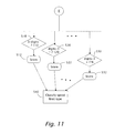
- FIG. 11 is a continuation E of method 350 shown in FIGS. 6 , 7 , 8 , 9 and 10 , showing non-binary classification three digit speed limit type traffic signs 20 a , according to embodiments of the present invention.
- the non-binary classification classifies each candidate three digit speed limit type traffic signs 20 a against training sets of all possible three digit speed limit type traffic signs 20 a , for example: 110 , 120 , 130 , etc (steps 510 , 520 and 530 ).
- the classification against each training set receives a score (steps 512 , 522 and 532 ).
- method 350 selects the highest score the classify the candidate three digit speed limit type traffic signs 20 a to the class associated with the highest score.
- FIG. 12 is a continuation F of method 350 shown in FIGS. 6 , 7 , 8 , 9 and 10 , showing non-binary classification two digit speed limit type traffic signs 20 a , according to embodiments of the present invention.
- the non-binary classification classifies each candidate two digit speed limit type traffic signs 20 a against training sets of all possible two digit speed limit type traffic signs 20 a , for example: 70, 80, 90 MPH, etc (steps 550 , 560 and 570 ).
- the classification against each training set receives a score (steps 552 , 562 and 572 ).
- method 350 selects the highest score to classify the candidate two digit speed limit type traffic signs 20 a into the class associated with the highest score.
- type X of circular traffic sign 20 a can be any circular traffic sign 20 a used or a subset of all possible circular traffic sign 20 a . It should be further noted that method 350 is given by way of example only and other TS 20 shapes and types can be classified in similar ways. The classification order can also be change and the set of traffic signs 20 that are of interest can be changed.
Abstract
Description
-
- first we approximate circles as squares and look for edge support along the center portion of the sides of the square. We use a clever manipulation of the bitmaps to get higher throughput but could alternatively have used specialized hardware, too.
- Then we approximate the circle as an octagon and look for diagonal support at 45 degrees
- Finally we look for circles using the Hough transform to detect the circles and then a classifier for accurate positioning.
Claims (7)
Priority Applications (1)
| Application Number | Priority Date | Filing Date | Title |
|---|---|---|---|
| US13/235,602 US8995723B2 (en) | 2006-12-06 | 2011-09-19 | Detecting and recognizing traffic signs |
Applications Claiming Priority (3)
| Application Number | Priority Date | Filing Date | Title |
|---|---|---|---|
| US86878306P | 2006-12-06 | 2006-12-06 | |
| US11/951,405 US8064643B2 (en) | 2006-12-06 | 2007-12-06 | Detecting and recognizing traffic signs |
| US13/235,602 US8995723B2 (en) | 2006-12-06 | 2011-09-19 | Detecting and recognizing traffic signs |
Related Parent Applications (1)
| Application Number | Title | Priority Date | Filing Date |
|---|---|---|---|
| US11/951,405 Continuation US8064643B2 (en) | 2006-12-06 | 2007-12-06 | Detecting and recognizing traffic signs |
Publications (2)
| Publication Number | Publication Date |
|---|---|
| US20120002053A1 US20120002053A1 (en) | 2012-01-05 |
| US8995723B2 true US8995723B2 (en) | 2015-03-31 |
Family
ID=39190302
Family Applications (2)
| Application Number | Title | Priority Date | Filing Date |
|---|---|---|---|
| US11/951,405 Active 2030-09-20 US8064643B2 (en) | 2006-12-06 | 2007-12-06 | Detecting and recognizing traffic signs |
| US13/235,602 Active 2030-01-21 US8995723B2 (en) | 2006-12-06 | 2011-09-19 | Detecting and recognizing traffic signs |
Family Applications Before (1)
| Application Number | Title | Priority Date | Filing Date |
|---|---|---|---|
| US11/951,405 Active 2030-09-20 US8064643B2 (en) | 2006-12-06 | 2007-12-06 | Detecting and recognizing traffic signs |
Country Status (3)
| Country | Link |
|---|---|
| US (2) | US8064643B2 (en) |
| EP (3) | EP1930863B1 (en) |
| AT (1) | ATE519193T1 (en) |
Cited By (9)
| Publication number | Priority date | Publication date | Assignee | Title |
|---|---|---|---|---|
| US9177212B2 (en) | 2010-06-15 | 2015-11-03 | Conti Temic Microelectronic Gmbh | Method for combining a road sign recognition system and a lane detection system of a motor vehicle |
| US9436879B2 (en) | 2011-08-04 | 2016-09-06 | Conti Temic Microelectronic Gmbh | Method for recognizing traffic signs |
| US9697430B2 (en) | 2013-10-01 | 2017-07-04 | Conti Temic Microelectronic Gmbh | Method and apparatus for identifying road signs |
| US10025998B1 (en) * | 2011-06-09 | 2018-07-17 | Mobileye Vision Technologies Ltd. | Object detection using candidate object alignment |
| US10493900B2 (en) | 2018-05-04 | 2019-12-03 | International Business Machines Corporation | Adaptive headlights for the trajectory of a vehicle |
| US10657393B2 (en) * | 2017-09-20 | 2020-05-19 | Aptiv Technologies Limited | Device and a method for distinguishing between traversable and nontraversable objects |
| US10990835B2 (en) * | 2017-01-25 | 2021-04-27 | Wuhan Jimu Intelligent Technology Co., Ltd. | Road sign recognition method and system |
| US11183055B2 (en) * | 2020-03-12 | 2021-11-23 | Here Global B.V. | Methods and systems for classifying a speed sign |
| US11282384B2 (en) | 2019-11-29 | 2022-03-22 | Brennan James McClay | Traffic light camera and speed camera notification system and method |
Families Citing this family (233)
| Publication number | Priority date | Publication date | Assignee | Title |
|---|---|---|---|---|
| US5877897A (en) | 1993-02-26 | 1999-03-02 | Donnelly Corporation | Automatic rearview mirror, vehicle lighting control and vehicle interior monitoring system using a photosensor array |
| US6822563B2 (en) | 1997-09-22 | 2004-11-23 | Donnelly Corporation | Vehicle imaging system with accessory control |
| US6891563B2 (en) | 1996-05-22 | 2005-05-10 | Donnelly Corporation | Vehicular vision system |
| US7655894B2 (en) | 1996-03-25 | 2010-02-02 | Donnelly Corporation | Vehicular image sensing system |
| US7697027B2 (en) | 2001-07-31 | 2010-04-13 | Donnelly Corporation | Vehicular video system |
| EP1504276B1 (en) | 2002-05-03 | 2012-08-08 | Donnelly Corporation | Object detection system for vehicle |
| US7526103B2 (en) | 2004-04-15 | 2009-04-28 | Donnelly Corporation | Imaging system for vehicle |
| US7881496B2 (en) | 2004-09-30 | 2011-02-01 | Donnelly Corporation | Vision system for vehicle |
| US7720580B2 (en) | 2004-12-23 | 2010-05-18 | Donnelly Corporation | Object detection system for vehicle |
| WO2008024639A2 (en) | 2006-08-11 | 2008-02-28 | Donnelly Corporation | Automatic headlamp control system |
| EP1930863B1 (en) | 2006-12-06 | 2011-08-03 | Mobileye Technologies Limited | Detecting and recognizing traffic signs |
| DE102007034505A1 (en) * | 2007-07-24 | 2009-01-29 | Hella Kgaa Hueck & Co. | Method and device for traffic sign recognition |
| US8017898B2 (en) | 2007-08-17 | 2011-09-13 | Magna Electronics Inc. | Vehicular imaging system in an automatic headlamp control system |
| US8254635B2 (en) | 2007-12-06 | 2012-08-28 | Gideon Stein | Bundling of driver assistance systems |
| US20090177378A1 (en) * | 2008-01-07 | 2009-07-09 | Theo Kamalski | Navigation device and method |
| US9176006B2 (en) | 2008-01-15 | 2015-11-03 | Mobileye Vision Technologies Ltd. | Detection and classification of light sources using a diffraction grating |
| DE102008022064A1 (en) * | 2008-05-03 | 2009-11-05 | Adc Automotive Distance Control Systems Gmbh | Method for exposure control for a camera in a motor vehicle |
| IT1397341B1 (en) * | 2008-07-28 | 2013-01-10 | Kft Spa | SYSTEM AND METHOD OF CHECKING AND ASSISTING THE DRIVING OF A MOTOR VEHICLE. |
| DE202008017672U1 (en) * | 2008-09-11 | 2010-04-22 | Twachtmann, Heinz-Werner | Device for preventing driving against the prescribed direction of travel |
| US8259998B2 (en) | 2008-09-30 | 2012-09-04 | Mazda Motor Corporation | Image processing device for vehicle |
| US9459515B2 (en) | 2008-12-05 | 2016-10-04 | Mobileye Vision Technologies Ltd. | Adjustable camera mount for a vehicle windshield |
| DE102008062154B4 (en) * | 2008-12-16 | 2021-08-26 | Volkswagen Ag | Control of a camera system of a motor vehicle and driver assistance system |
| US20100157061A1 (en) * | 2008-12-24 | 2010-06-24 | Igor Katsman | Device and method for handheld device based vehicle monitoring and driver assistance |
| US8675122B2 (en) * | 2009-01-16 | 2014-03-18 | Microsoft Corporation | Determining exposure time in a digital camera |
| EP2209091B1 (en) * | 2009-01-16 | 2012-08-08 | Honda Research Institute Europe GmbH | System and method for object motion detection based on multiple 3D warping and vehicle equipped with such system |
| US8812226B2 (en) * | 2009-01-26 | 2014-08-19 | GM Global Technology Operations LLC | Multiobject fusion module for collision preparation system |
| WO2010115020A2 (en) * | 2009-04-01 | 2010-10-07 | Robert Daniel Mcathur | Color and pattern detection system |
| US8376595B2 (en) * | 2009-05-15 | 2013-02-19 | Magna Electronics, Inc. | Automatic headlamp control |
| DE102009036433A1 (en) | 2009-08-06 | 2010-05-06 | Daimler Ag | Method for operating driver assistance system, involves recording images adjacent to vehicle, where indicators of hazard- or construction sites are determined by images |
| DE102009043764A1 (en) * | 2009-09-30 | 2011-04-07 | GM Global Technology Operations, Inc., Detroit | Navigation device and navigation method for a vehicle |
| DE102009043705A1 (en) * | 2009-10-01 | 2011-04-07 | Silicon Micro Sensors Gmbh | Method and camera system for generating images for transmission to an external control unit |
| DE102009048066A1 (en) | 2009-10-01 | 2011-04-07 | Conti Temic Microelectronic Gmbh | Procedure for traffic sign recognition |
| US8538205B2 (en) * | 2010-05-14 | 2013-09-17 | Mobileye Technologies Ltd. | Multi-function summing machine |
| US9269001B2 (en) * | 2010-06-10 | 2016-02-23 | Tata Consultancy Services Limited | Illumination invariant and robust apparatus and method for detecting and recognizing various traffic signs |
| US9959595B2 (en) | 2010-09-21 | 2018-05-01 | Mobileye Vision Technologies Ltd. | Dense structure from motion |
| US9280711B2 (en) | 2010-09-21 | 2016-03-08 | Mobileye Vision Technologies Ltd. | Barrier and guardrail detection using a single camera |
| EP2447884B1 (en) * | 2010-10-28 | 2014-12-17 | CycloMedia Technology B.V. | Method for detecting and recognising an object in an image, and an apparatus and a computer program therefor |
| EP3588939B1 (en) | 2010-10-31 | 2023-10-18 | Mobileye Vision Technologies Ltd. | Bundling night vision and other driver assistance systems (das) using near infra red (nir) illumination and a rolling shutter |
| WO2012075250A1 (en) | 2010-12-01 | 2012-06-07 | Magna Electronics Inc. | System and method of establishing a multi-camera image using pixel remapping |
| US9547795B2 (en) | 2011-04-25 | 2017-01-17 | Magna Electronics Inc. | Image processing method for detecting objects using relative motion |
| US9357208B2 (en) | 2011-04-25 | 2016-05-31 | Magna Electronics Inc. | Method and system for dynamically calibrating vehicular cameras |
| US9834153B2 (en) | 2011-04-25 | 2017-12-05 | Magna Electronics Inc. | Method and system for dynamically calibrating vehicular cameras |
| WO2013016409A1 (en) | 2011-07-26 | 2013-01-31 | Magna Electronics Inc. | Vision system for vehicle |
| US9491450B2 (en) | 2011-08-01 | 2016-11-08 | Magna Electronic Inc. | Vehicle camera alignment system |
| DE112012003931T5 (en) | 2011-09-21 | 2014-07-10 | Magna Electronics, Inc. | Image processing system for a motor vehicle with image data transmission and power supply via a coaxial cable |
| CN103020623B (en) | 2011-09-23 | 2016-04-06 | 株式会社理光 | Method for traffic sign detection and road traffic sign detection equipment |
| US9491451B2 (en) | 2011-11-15 | 2016-11-08 | Magna Electronics Inc. | Calibration system and method for vehicular surround vision system |
| US10099614B2 (en) | 2011-11-28 | 2018-10-16 | Magna Electronics Inc. | Vision system for vehicle |
| WO2013086249A2 (en) | 2011-12-09 | 2013-06-13 | Magna Electronics, Inc. | Vehicle vision system with customized display |
| US10457209B2 (en) | 2012-02-22 | 2019-10-29 | Magna Electronics Inc. | Vehicle vision system with multi-paned view |
| WO2013126715A2 (en) | 2012-02-22 | 2013-08-29 | Magna Electronics, Inc. | Vehicle camera system with image manipulation |
| US9319637B2 (en) | 2012-03-27 | 2016-04-19 | Magna Electronics Inc. | Vehicle vision system with lens pollution detection |
| US9365162B2 (en) * | 2012-08-20 | 2016-06-14 | Magna Electronics Inc. | Method of obtaining data relating to a driver assistance system of a vehicle |
| US8996228B1 (en) | 2012-09-05 | 2015-03-31 | Google Inc. | Construction zone object detection using light detection and ranging |
| US9056395B1 (en) * | 2012-09-05 | 2015-06-16 | Google Inc. | Construction zone sign detection using light detection and ranging |
| US9195914B2 (en) | 2012-09-05 | 2015-11-24 | Google Inc. | Construction zone sign detection |
| US11798444B2 (en) | 2012-09-12 | 2023-10-24 | Delorean, Llc | Controlling display of variable content sign |
| US9723272B2 (en) | 2012-10-05 | 2017-08-01 | Magna Electronics Inc. | Multi-camera image stitching calibration system |
| DE102012024613A1 (en) * | 2012-12-17 | 2014-06-18 | GM Global Technology Operations LLC (n. d. Gesetzen des Staates Delaware) | Method for operating e.g. car, involves determining recorded signs having specific traffic rule for vehicle combinations with trailer based on obtained data, if connection between vehicle and trailer is made through coupling device |
| US10462442B2 (en) * | 2012-12-20 | 2019-10-29 | Brett I. Walker | Apparatus, systems and methods for monitoring vehicular activity |
| CN103049751A (en) * | 2013-01-24 | 2013-04-17 | 苏州大学 | Improved weighting region matching high-altitude video pedestrian recognizing method |
| CN103150901B (en) * | 2013-02-05 | 2015-02-18 | 长安大学 | Abnormal traffic condition detection method based on vehicle motion vector field analysis |
| US9445057B2 (en) | 2013-02-20 | 2016-09-13 | Magna Electronics Inc. | Vehicle vision system with dirt detection |
| US10179543B2 (en) | 2013-02-27 | 2019-01-15 | Magna Electronics Inc. | Multi-camera dynamic top view vision system |
| WO2014134194A1 (en) | 2013-02-27 | 2014-09-04 | Gentex Corporation | System and method for monitoring vehicle speed with driver notification |
| US9688200B2 (en) | 2013-03-04 | 2017-06-27 | Magna Electronics Inc. | Calibration system and method for multi-camera vision system |
| US9092696B2 (en) * | 2013-03-26 | 2015-07-28 | Hewlett-Packard Development Company, L.P. | Image sign classifier |
| US9508014B2 (en) | 2013-05-06 | 2016-11-29 | Magna Electronics Inc. | Vehicular multi-camera vision system |
| US9205776B2 (en) | 2013-05-21 | 2015-12-08 | Magna Electronics Inc. | Vehicle vision system using kinematic model of vehicle motion |
| US9563951B2 (en) | 2013-05-21 | 2017-02-07 | Magna Electronics Inc. | Vehicle vision system with targetless camera calibration |
| JP6484228B2 (en) * | 2013-06-13 | 2019-03-13 | モービルアイ ビジョン テクノロジーズ リミテッド | Visually enhanced navigation |
| KR101353052B1 (en) * | 2013-07-31 | 2014-01-20 | 주식회사 피엘케이 테크놀로지 | Image recognition system for vehicle for recognizing traffic signs |
| KR101912914B1 (en) * | 2014-01-17 | 2018-10-29 | 주식회사 만도 | Method and system for recognition of speed limit sign using front camera |
| US9233688B2 (en) | 2014-01-30 | 2016-01-12 | Mobileye Vision Technologies Ltd. | Systems and methods for lane end recognition |
| JP6024679B2 (en) * | 2014-02-03 | 2016-11-16 | 株式会社デンソー | Sign recognition device |
| US9487235B2 (en) | 2014-04-10 | 2016-11-08 | Magna Electronics Inc. | Vehicle control system with adaptive wheel angle correction |
| KR20150121977A (en) * | 2014-04-22 | 2015-10-30 | 주식회사 만도 | Traffic signs recognition apparatus and method for outputing limiting speed of the same |
| JP6463011B2 (en) * | 2014-06-25 | 2019-01-30 | 三菱電機株式会社 | Information display device |
| US9336448B2 (en) | 2014-08-11 | 2016-05-10 | Here Global B.V. | Variable speed sign value prediction and confidence modeling |
| US9424475B1 (en) * | 2014-09-17 | 2016-08-23 | Google Inc. | Construction object detection |
| US10109184B2 (en) | 2014-10-08 | 2018-10-23 | Here Global B.V. | Probe based variable speed sign value |
| US9460355B2 (en) | 2014-10-14 | 2016-10-04 | Here Global B.V. | Lateral sign placement determination |
| KR20170105481A (en) * | 2014-10-14 | 2017-09-19 | 도요타 모터 유럽 | Systems and methods for traffic sign validation |
| EP3018027B1 (en) * | 2014-11-10 | 2017-06-07 | Volvo Car Corporation | Control arrangement arranged to control an autonomous vehicle, autonomous drive arrangement, vehicle and method |
| WO2016103258A1 (en) * | 2014-12-24 | 2016-06-30 | Raiman Timor | System and method for preventing accidents |
| KR102323393B1 (en) * | 2015-01-12 | 2021-11-09 | 삼성전자주식회사 | Device and method of controlling the device |
| US9916660B2 (en) | 2015-01-16 | 2018-03-13 | Magna Electronics Inc. | Vehicle vision system with calibration algorithm |
| CA3067177A1 (en) | 2015-02-10 | 2016-08-18 | Mobileye Vision Technologies Ltd. | Sparse map for autonomous vehicle navigation |
| CN104732211B (en) * | 2015-03-19 | 2017-12-08 | 杭州电子科技大学 | A kind of method for traffic sign detection based on adaptive threshold |
| DE102015205524B4 (en) * | 2015-03-26 | 2020-11-05 | Mando Corporation | Method and device for classifying an object, for example a traffic sign, in an image |
| US10946799B2 (en) | 2015-04-21 | 2021-03-16 | Magna Electronics Inc. | Vehicle vision system with overlay calibration |
| DE102015207902A1 (en) * | 2015-04-29 | 2016-11-03 | Mando Corporation | Method and device for confirming the relevant inner white circle in the recognition of the environment of a circular traffic sign |
| JP6319173B2 (en) * | 2015-05-11 | 2018-05-09 | トヨタ自動車株式会社 | Vehicle regulation speed display device |
| JP6396850B2 (en) * | 2015-05-29 | 2018-09-26 | 株式会社デンソー | Driving support device and driving support method |
| JP6412464B2 (en) * | 2015-05-29 | 2018-10-24 | 株式会社デンソー | Unit setting device, unit setting method |
| GB2538968B (en) * | 2015-06-01 | 2018-11-28 | Jaguar Land Rover Ltd | Controller |
| DE102015010292B3 (en) | 2015-08-07 | 2017-01-26 | Audi Ag | A method for assisting a driver to time-efficiently perform a journey with a motor vehicle and motor vehicle |
| EP3144197B1 (en) | 2015-09-15 | 2021-07-14 | Ford Global Technologies, LLC | Method for automatically adapting acceleration in a motor vehicle |
| US11228700B2 (en) | 2015-10-07 | 2022-01-18 | Magna Electronics Inc. | Vehicle vision system camera with adaptive field of view |
| US10187590B2 (en) | 2015-10-27 | 2019-01-22 | Magna Electronics Inc. | Multi-camera vehicle vision system with image gap fill |
| US9607513B1 (en) * | 2015-12-03 | 2017-03-28 | Denso International America, Inc. | Systems and methods for informing driver of lane passing regulations |
| JP6540482B2 (en) * | 2015-12-04 | 2019-07-10 | 株式会社デンソー | INFORMATION PROCESSING SYSTEM, INFORMATION PROCESSING DEVICE, AND OUTPUT CONTROL METHOD |
| EP3182373B1 (en) * | 2015-12-17 | 2019-06-19 | STMicroelectronics S.A. | Improvements in determination of an ego-motion of a video apparatus in a slam type algorithm |
| EP3182370B1 (en) | 2015-12-17 | 2020-07-29 | STmicroelectronics SA | Method and device for generating binary descriptors in video frames |
| EP3185212B1 (en) | 2015-12-17 | 2019-07-03 | STmicroelectronics SA | Dynamic particle filter parameterization |
| EP3182371B1 (en) | 2015-12-17 | 2018-09-26 | Stmicroelectronics Sa | Threshold determination in for example a type ransac algorithm |
| DE102015225900B3 (en) * | 2015-12-18 | 2017-04-06 | Continental Automotive Gmbh | Method and device for camera-based traffic sign recognition in a motor vehicle |
| CN105718904A (en) * | 2016-01-25 | 2016-06-29 | 大连楼兰科技股份有限公司 | Blind people detection and identification method and system based on combined characteristics and vehicle-mounted cameras |
| US11277558B2 (en) | 2016-02-01 | 2022-03-15 | Magna Electronics Inc. | Vehicle vision system with master-slave camera configuration |
| US11433809B2 (en) | 2016-02-02 | 2022-09-06 | Magna Electronics Inc. | Vehicle vision system with smart camera video output |
| JP6552979B2 (en) * | 2016-02-16 | 2019-07-31 | 株式会社日立製作所 | Image processing device, warning device, image processing system, and image processing method |
| EP3229172A1 (en) * | 2016-04-04 | 2017-10-11 | Conti Temic microelectronic GmbH | Driver assistance system with variable image resolution |
| US10325339B2 (en) | 2016-04-26 | 2019-06-18 | Qualcomm Incorporated | Method and device for capturing image of traffic sign |
| KR101843774B1 (en) * | 2016-05-18 | 2018-03-30 | 엘지전자 주식회사 | Driver assistance apparatus and Vehicle |
| US10300859B2 (en) | 2016-06-10 | 2019-05-28 | Magna Electronics Inc. | Multi-sensor interior mirror device with image adjustment |
| US10838426B2 (en) | 2016-07-21 | 2020-11-17 | Mobileye Vision Technologies Ltd. | Distributing a crowdsourced sparse map for autonomous vehicle navigation |
| WO2018015811A1 (en) * | 2016-07-21 | 2018-01-25 | Mobileye Vision Technologies Ltd. | Crowdsourcing and distributing a sparse map, and lane measurements for autonomous vehicle navigation |
| US20180091797A1 (en) * | 2016-09-27 | 2018-03-29 | The Boeing Company | Apparatus and method of compensating for relative motion of at least two aircraft-mounted cameras |
| DE102016118538A1 (en) | 2016-09-29 | 2018-03-29 | Valeo Schalter Und Sensoren Gmbh | Method for classifying a traffic sign in a surrounding area of a motor vehicle, computing device, driver assistance system and motor vehicle |
| US10750119B2 (en) | 2016-10-17 | 2020-08-18 | Magna Electronics Inc. | Vehicle camera LVDS repeater |
| DE102016120166A1 (en) | 2016-10-24 | 2018-04-26 | Connaught Electronics Ltd. | Controlling a vehicle depending on the environment |
| US10452076B2 (en) | 2017-01-04 | 2019-10-22 | Magna Electronics Inc. | Vehicle vision system with adjustable computation and data compression |
| US10671873B2 (en) | 2017-03-10 | 2020-06-02 | Tusimple, Inc. | System and method for vehicle wheel detection |
| US10311312B2 (en) | 2017-08-31 | 2019-06-04 | TuSimple | System and method for vehicle occlusion detection |
| US10067509B1 (en) | 2017-03-10 | 2018-09-04 | TuSimple | System and method for occluding contour detection |
| US11587304B2 (en) | 2017-03-10 | 2023-02-21 | Tusimple, Inc. | System and method for occluding contour detection |
| US10147193B2 (en) | 2017-03-10 | 2018-12-04 | TuSimple | System and method for semantic segmentation using hybrid dilated convolution (HDC) |
| US9953236B1 (en) | 2017-03-10 | 2018-04-24 | TuSimple | System and method for semantic segmentation using dense upsampling convolution (DUC) |
| US9952594B1 (en) | 2017-04-07 | 2018-04-24 | TuSimple | System and method for traffic data collection using unmanned aerial vehicles (UAVs) |
| US10710592B2 (en) | 2017-04-07 | 2020-07-14 | Tusimple, Inc. | System and method for path planning of autonomous vehicles based on gradient |
| US10471963B2 (en) | 2017-04-07 | 2019-11-12 | TuSimple | System and method for transitioning between an autonomous and manual driving mode based on detection of a drivers capacity to control a vehicle |
| US10552691B2 (en) | 2017-04-25 | 2020-02-04 | TuSimple | System and method for vehicle position and velocity estimation based on camera and lidar data |
| US10481044B2 (en) | 2017-05-18 | 2019-11-19 | TuSimple | Perception simulation for improved autonomous vehicle control |
| US10558864B2 (en) | 2017-05-18 | 2020-02-11 | TuSimple | System and method for image localization based on semantic segmentation |
| US10474790B2 (en) | 2017-06-02 | 2019-11-12 | TuSimple | Large scale distributed simulation for realistic multiple-agent interactive environments |
| US10762635B2 (en) | 2017-06-14 | 2020-09-01 | Tusimple, Inc. | System and method for actively selecting and labeling images for semantic segmentation |
| US10308242B2 (en) | 2017-07-01 | 2019-06-04 | TuSimple | System and method for using human driving patterns to detect and correct abnormal driving behaviors of autonomous vehicles |
| US10493988B2 (en) | 2017-07-01 | 2019-12-03 | TuSimple | System and method for adaptive cruise control for defensive driving |
| US10752246B2 (en) | 2017-07-01 | 2020-08-25 | Tusimple, Inc. | System and method for adaptive cruise control with proximate vehicle detection |
| US10737695B2 (en) | 2017-07-01 | 2020-08-11 | Tusimple, Inc. | System and method for adaptive cruise control for low speed following |
| US10303522B2 (en) | 2017-07-01 | 2019-05-28 | TuSimple | System and method for distributed graphics processing unit (GPU) computation |
| CN107302587A (en) * | 2017-07-18 | 2017-10-27 | 清远墨墨教育科技有限公司 | A kind of recording learning situation register with mend label method |
| US10360257B2 (en) | 2017-08-08 | 2019-07-23 | TuSimple | System and method for image annotation |
| US11029693B2 (en) | 2017-08-08 | 2021-06-08 | Tusimple, Inc. | Neural network based vehicle dynamics model |
| US10816354B2 (en) | 2017-08-22 | 2020-10-27 | Tusimple, Inc. | Verification module system and method for motion-based lane detection with multiple sensors |
| US10303956B2 (en) | 2017-08-23 | 2019-05-28 | TuSimple | System and method for using triplet loss for proposal free instance-wise semantic segmentation for lane detection |
| US10762673B2 (en) | 2017-08-23 | 2020-09-01 | Tusimple, Inc. | 3D submap reconstruction system and method for centimeter precision localization using camera-based submap and LiDAR-based global map |
| US10565457B2 (en) | 2017-08-23 | 2020-02-18 | Tusimple, Inc. | Feature matching and correspondence refinement and 3D submap position refinement system and method for centimeter precision localization using camera-based submap and LiDAR-based global map |
| US10678234B2 (en) | 2017-08-24 | 2020-06-09 | Tusimple, Inc. | System and method for autonomous vehicle control to minimize energy cost |
| US10783381B2 (en) | 2017-08-31 | 2020-09-22 | Tusimple, Inc. | System and method for vehicle occlusion detection |
| US10782693B2 (en) | 2017-09-07 | 2020-09-22 | Tusimple, Inc. | Prediction-based system and method for trajectory planning of autonomous vehicles |
| US10656644B2 (en) | 2017-09-07 | 2020-05-19 | Tusimple, Inc. | System and method for using human driving patterns to manage speed control for autonomous vehicles |
| US10953881B2 (en) | 2017-09-07 | 2021-03-23 | Tusimple, Inc. | System and method for automated lane change control for autonomous vehicles |
| US10782694B2 (en) | 2017-09-07 | 2020-09-22 | Tusimple, Inc. | Prediction-based system and method for trajectory planning of autonomous vehicles |
| US10953880B2 (en) | 2017-09-07 | 2021-03-23 | Tusimple, Inc. | System and method for automated lane change control for autonomous vehicles |
| US10649458B2 (en) | 2017-09-07 | 2020-05-12 | Tusimple, Inc. | Data-driven prediction-based system and method for trajectory planning of autonomous vehicles |
| US10671083B2 (en) | 2017-09-13 | 2020-06-02 | Tusimple, Inc. | Neural network architecture system for deep odometry assisted by static scene optical flow |
| US10552979B2 (en) | 2017-09-13 | 2020-02-04 | TuSimple | Output of a neural network method for deep odometry assisted by static scene optical flow |
| US10552692B2 (en) | 2017-09-19 | 2020-02-04 | Ford Global Technologies, Llc | Color learning |
| US10387736B2 (en) | 2017-09-20 | 2019-08-20 | TuSimple | System and method for detecting taillight signals of a vehicle |
| US10733465B2 (en) | 2017-09-20 | 2020-08-04 | Tusimple, Inc. | System and method for vehicle taillight state recognition |
| JP6886079B2 (en) | 2017-09-26 | 2021-06-16 | 日立Astemo株式会社 | Camera calibration systems and methods using traffic sign recognition, and computer-readable media |
| US10962979B2 (en) | 2017-09-30 | 2021-03-30 | Tusimple, Inc. | System and method for multitask processing for autonomous vehicle computation and control |
| US10768626B2 (en) | 2017-09-30 | 2020-09-08 | Tusimple, Inc. | System and method for providing multiple agents for decision making, trajectory planning, and control for autonomous vehicles |
| US10970564B2 (en) | 2017-09-30 | 2021-04-06 | Tusimple, Inc. | System and method for instance-level lane detection for autonomous vehicle control |
| US10410055B2 (en) | 2017-10-05 | 2019-09-10 | TuSimple | System and method for aerial video traffic analysis |
| DE102017218192A1 (en) * | 2017-10-12 | 2019-04-18 | Robert Bosch Gmbh | Method and device for traffic sign recognition |
| EP3477616A1 (en) | 2017-10-27 | 2019-05-01 | Sigra Technologies GmbH | Method for controlling a vehicle using a machine learning system |
| US10666730B2 (en) | 2017-10-28 | 2020-05-26 | Tusimple, Inc. | Storage architecture for heterogeneous multimedia data |
| US10739775B2 (en) | 2017-10-28 | 2020-08-11 | Tusimple, Inc. | System and method for real world autonomous vehicle trajectory simulation |
| US10812589B2 (en) | 2017-10-28 | 2020-10-20 | Tusimple, Inc. | Storage architecture for heterogeneous multimedia data |
| US10528851B2 (en) | 2017-11-27 | 2020-01-07 | TuSimple | System and method for drivable road surface representation generation using multimodal sensor data |
| US10657390B2 (en) | 2017-11-27 | 2020-05-19 | Tusimple, Inc. | System and method for large-scale lane marking detection using multimodal sensor data |
| US10528823B2 (en) | 2017-11-27 | 2020-01-07 | TuSimple | System and method for large-scale lane marking detection using multimodal sensor data |
| US10860018B2 (en) | 2017-11-30 | 2020-12-08 | Tusimple, Inc. | System and method for generating simulated vehicles with configured behaviors for analyzing autonomous vehicle motion planners |
| US10877476B2 (en) | 2017-11-30 | 2020-12-29 | Tusimple, Inc. | Autonomous vehicle simulation system for analyzing motion planners |
| US11525688B2 (en) | 2017-12-15 | 2022-12-13 | Samsung Electronics Co., Ltd. | Method and apparatus for determining object position |
| KR102521656B1 (en) | 2018-01-03 | 2023-04-13 | 삼성전자주식회사 | Method and apparatus of identifying object |
| US10642269B2 (en) * | 2018-01-03 | 2020-05-05 | Denso International America, Inc. | Vehicle localization system |
| CN110248861B (en) | 2018-01-07 | 2023-05-30 | 辉达公司 | Guiding a vehicle using a machine learning model during vehicle maneuvers |
| EP4283430A3 (en) | 2018-01-09 | 2024-01-24 | Tusimple, Inc. | Real-time remote control of vehicles with high redundancy |
| CN111989716B (en) | 2018-01-11 | 2022-11-15 | 图森有限公司 | Monitoring system for autonomous vehicle operation |
| WO2019152888A1 (en) | 2018-02-02 | 2019-08-08 | Nvidia Corporation | Safety procedure analysis for obstacle avoidance in autonomous vehicle |
| KR102541561B1 (en) | 2018-02-12 | 2023-06-08 | 삼성전자주식회사 | Method of providing information for driving vehicle and apparatus thereof |
| US11009356B2 (en) | 2018-02-14 | 2021-05-18 | Tusimple, Inc. | Lane marking localization and fusion |
| US11009365B2 (en) | 2018-02-14 | 2021-05-18 | Tusimple, Inc. | Lane marking localization |
| CN111133447B (en) | 2018-02-18 | 2024-03-19 | 辉达公司 | Method and system for object detection and detection confidence for autonomous driving |
| DE112019000122T5 (en) | 2018-02-27 | 2020-06-25 | Nvidia Corporation | REAL-TIME DETECTION OF TRACKS AND LIMITATIONS BY AUTONOMOUS VEHICLES |
| US10685244B2 (en) | 2018-02-27 | 2020-06-16 | Tusimple, Inc. | System and method for online real-time multi-object tracking |
| JP7199150B2 (en) * | 2018-03-12 | 2023-01-05 | 本田技研工業株式会社 | VEHICLE CONTROL DEVICE, VEHICLE CONTROL METHOD, AND PROGRAM |
| CN110494863B (en) | 2018-03-15 | 2024-02-09 | 辉达公司 | Determining drivable free space of an autonomous vehicle |
| US10685239B2 (en) | 2018-03-18 | 2020-06-16 | Tusimple, Inc. | System and method for lateral vehicle detection |
| CN111278704B (en) * | 2018-03-20 | 2023-07-28 | 御眼视觉技术有限公司 | System and method for navigating a vehicle |
| WO2019182974A2 (en) | 2018-03-21 | 2019-09-26 | Nvidia Corporation | Stereo depth estimation using deep neural networks |
| CN111919225B (en) | 2018-03-27 | 2024-03-26 | 辉达公司 | Training, testing, and validating autonomous machines using a simulated environment |
| CN110378185A (en) | 2018-04-12 | 2019-10-25 | 北京图森未来科技有限公司 | A kind of image processing method applied to automatic driving vehicle, device |
| CN116129376A (en) | 2018-05-02 | 2023-05-16 | 北京图森未来科技有限公司 | Road edge detection method and device |
| US11104334B2 (en) | 2018-05-31 | 2021-08-31 | Tusimple, Inc. | System and method for proximate vehicle intention prediction for autonomous vehicles |
| CN109263659A (en) * | 2018-07-28 | 2019-01-25 | 上海商汤智能科技有限公司 | Intelligent driving control method and device, vehicle, electronic equipment, medium, product |
| US10839234B2 (en) | 2018-09-12 | 2020-11-17 | Tusimple, Inc. | System and method for three-dimensional (3D) object detection |
| US11292480B2 (en) | 2018-09-13 | 2022-04-05 | Tusimple, Inc. | Remote safe driving methods and systems |
| US10796402B2 (en) | 2018-10-19 | 2020-10-06 | Tusimple, Inc. | System and method for fisheye image processing |
| US10942271B2 (en) | 2018-10-30 | 2021-03-09 | Tusimple, Inc. | Determining an angle between a tow vehicle and a trailer |
| CN111127923B (en) * | 2018-10-31 | 2021-01-29 | 驭势科技(北京)有限公司 | Equipment and method for analyzing indication mark |
| CN111178119A (en) * | 2018-11-13 | 2020-05-19 | 北京市商汤科技开发有限公司 | Intersection state detection method and device, electronic equipment and vehicle |
| WO2020102733A1 (en) | 2018-11-16 | 2020-05-22 | Nvidia Corporation | Learning to generate synthetic datasets for training neural networks |
| JP7044038B2 (en) * | 2018-11-21 | 2022-03-30 | トヨタ自動車株式会社 | Map information system |
| US10928828B2 (en) * | 2018-12-14 | 2021-02-23 | Waymo Llc | Detecting unfamiliar signs |
| CN113228042A (en) | 2018-12-28 | 2021-08-06 | 辉达公司 | Distance of obstacle detection in autonomous machine applications |
| US11182916B2 (en) | 2018-12-28 | 2021-11-23 | Nvidia Corporation | Distance to obstacle detection in autonomous machine applications |
| US11170299B2 (en) | 2018-12-28 | 2021-11-09 | Nvidia Corporation | Distance estimation to objects and free-space boundaries in autonomous machine applications |
| WO2020163390A1 (en) | 2019-02-05 | 2020-08-13 | Nvidia Corporation | Driving lane perception diversity and redundancy in autonomous driving applications |
| US11648945B2 (en) | 2019-03-11 | 2023-05-16 | Nvidia Corporation | Intersection detection and classification in autonomous machine applications |
| US11823460B2 (en) | 2019-06-14 | 2023-11-21 | Tusimple, Inc. | Image fusion for autonomous vehicle operation |
| DE112020004139T5 (en) | 2019-08-31 | 2022-05-12 | Nvidia Corporation | MAP CREATION AND LOCALIZATION FOR AUTONOMOUS DRIVING APPLICATIONS |
| WO2021061921A1 (en) * | 2019-09-25 | 2021-04-01 | Delorean, Llc | Vehicle-mounted, motion-controlled sign |
| CN112784084B (en) * | 2019-11-08 | 2024-01-26 | 阿里巴巴集团控股有限公司 | Image processing method and device and electronic equipment |
| CN112793419B (en) * | 2019-11-13 | 2022-02-22 | 北京新能源汽车股份有限公司 | Vehicle speed limit display method and device and automobile |
| US11428535B2 (en) | 2019-12-06 | 2022-08-30 | Here Global B.V. | System and method for determining a sign type of a road sign |
| CN116026345A (en) * | 2020-01-03 | 2023-04-28 | 御眼视觉技术有限公司 | System and method for vehicle navigation |
| US11428550B2 (en) | 2020-03-03 | 2022-08-30 | Waymo Llc | Sensor region of interest selection based on multisensor data |
| EP3893150A1 (en) | 2020-04-09 | 2021-10-13 | Tusimple, Inc. | Camera pose estimation techniques |
| US11527161B2 (en) * | 2020-04-27 | 2022-12-13 | Here Global B.V. | Methods and systems for detecting a speed funnel in a region |
| US20210350152A1 (en) * | 2020-05-11 | 2021-11-11 | Toyota Research Institute, Inc. | Structural object detector for hierarchical ontology for traffic light handling |
| AU2021203567A1 (en) | 2020-06-18 | 2022-01-20 | Tusimple, Inc. | Angle and orientation measurements for vehicles with multiple drivable sections |
| CN112183528B (en) * | 2020-09-23 | 2022-06-21 | 桂林电子科技大学 | Method for tracking target vehicle, device, system and computer storage medium thereof |
| US11295147B1 (en) | 2020-11-27 | 2022-04-05 | HCL Technologies Italy S.p.A. | Method and system for detecting and managing obfuscation of a road sign |
| CN114572275A (en) * | 2020-12-02 | 2022-06-03 | 晋城三赢精密电子有限公司 | Vehicle driving assistance method, vehicle-mounted device, vehicle and storage medium |
| US11756283B2 (en) | 2020-12-16 | 2023-09-12 | Waymo Llc | Smart sensor implementations of region of interest operating modes |
| DE102021207258B3 (en) | 2021-07-08 | 2022-09-29 | Volkswagen Aktiengesellschaft | Method for automatically controlling at least one vehicle function of a vehicle and notification system for a vehicle |
| US11861915B2 (en) | 2021-09-03 | 2024-01-02 | Waymo Llc | Pipeline architecture for road sign detection and evaluation |
| CN114519759B (en) * | 2022-02-14 | 2023-11-14 | 同恩(上海)工程技术有限公司 | View transformation method, device and medium |
| CN115100870B (en) * | 2022-08-24 | 2022-11-15 | 北京百度网讯科技有限公司 | Speed limit sign verification method, automatic driving method and device and electronic equipment |
Citations (20)
| Publication number | Priority date | Publication date | Assignee | Title |
|---|---|---|---|---|
| US4987357A (en) | 1989-12-18 | 1991-01-22 | General Motors Corporation | Adaptive motor vehicle cruise control |
| US5850254A (en) | 1994-07-05 | 1998-12-15 | Hitachi, Ltd. | Imaging system for a vehicle which compares a reference image which includes a mark which is fixed to said vehicle to subsequent images |
| US6246961B1 (en) | 1998-06-09 | 2001-06-12 | Yazaki Corporation | Collision alarm method and apparatus for vehicles |
| US20030025597A1 (en) * | 2001-07-31 | 2003-02-06 | Kenneth Schofield | Automotive lane change aid |
| US6593698B2 (en) | 1998-09-18 | 2003-07-15 | Gentex Corporation | Continuously variable headlamp control |
| US6704621B1 (en) | 1999-11-26 | 2004-03-09 | Gideon P. Stein | System and method for estimating ego-motion of a moving vehicle using successive images recorded along the vehicle's path of motion |
| US20040148057A1 (en) * | 2000-05-08 | 2004-07-29 | Breed David S. | Vehicular exterior identification and monitoring system-agricultural product distribution |
| US6813545B2 (en) | 2002-07-09 | 2004-11-02 | Accenture Global Services Gmbh | Automatic traffic sign recognition |
| US20060034484A1 (en) * | 2004-08-16 | 2006-02-16 | Claus Bahlmann | Method for traffic sign detection |
| US7058206B1 (en) | 1998-11-14 | 2006-06-06 | Daimlerchrysler Ag | Method for increasing the power of a traffic sign recognition system |
| US20060125919A1 (en) | 2004-09-30 | 2006-06-15 | Joseph Camilleri | Vision system for vehicle |
| US7113867B1 (en) | 2000-11-26 | 2006-09-26 | Mobileye Technologies Limited | System and method for detecting obstacles to vehicle motion and determining time to contact therewith using sequences of images |
| US20070177014A1 (en) | 2004-05-25 | 2007-08-02 | Siemens Aktiengesellschaft | Monitoring unit alongside an assistance system for motor vehicles |
| US20070221822A1 (en) | 2006-03-24 | 2007-09-27 | Mobileye Technologies Ltd. | Headlight, Taillight And Streetlight Detection |
| US20070229238A1 (en) * | 2006-03-14 | 2007-10-04 | Mobileye Technologies Ltd. | Systems And Methods For Detecting Pedestrians In The Vicinity Of A Powered Industrial Vehicle |
| US7327855B1 (en) | 2001-06-20 | 2008-02-05 | Hrl Laboratories, Llc | Vision-based highway overhead structure detection system |
| US20080042812A1 (en) * | 2006-08-16 | 2008-02-21 | Dunsmoir John W | Systems And Arrangements For Providing Situational Awareness To An Operator Of A Vehicle |
| US20080068520A1 (en) * | 2006-03-09 | 2008-03-20 | Minikey Danny L Jr | Vehicle Rearview Mirror Assembly Including a High Intensity Display |
| EP1930863A2 (en) | 2006-12-06 | 2008-06-11 | MobilEye Technologies, Ltd. | Detecting and recognizing traffic signs |
| US7764808B2 (en) | 2003-03-24 | 2010-07-27 | Siemens Corporation | System and method for vehicle detection and tracking |
Family Cites Families (1)
| Publication number | Priority date | Publication date | Assignee | Title |
|---|---|---|---|---|
| AU2001253619A1 (en) | 2000-04-14 | 2001-10-30 | Mobileye, Inc. | Generating a model of the path of a roadway from an image recorded by a camera |
-
2007
- 2007-12-06 EP EP07122458A patent/EP1930863B1/en active Active
- 2007-12-06 AT AT07122458T patent/ATE519193T1/en not_active IP Right Cessation
- 2007-12-06 EP EP11175972.6A patent/EP2383713B1/en not_active Revoked
- 2007-12-06 US US11/951,405 patent/US8064643B2/en active Active
- 2007-12-06 EP EP11175975A patent/EP2383679A1/en not_active Withdrawn
-
2011
- 2011-09-19 US US13/235,602 patent/US8995723B2/en active Active
Patent Citations (21)
| Publication number | Priority date | Publication date | Assignee | Title |
|---|---|---|---|---|
| US4987357A (en) | 1989-12-18 | 1991-01-22 | General Motors Corporation | Adaptive motor vehicle cruise control |
| US5850254A (en) | 1994-07-05 | 1998-12-15 | Hitachi, Ltd. | Imaging system for a vehicle which compares a reference image which includes a mark which is fixed to said vehicle to subsequent images |
| US6246961B1 (en) | 1998-06-09 | 2001-06-12 | Yazaki Corporation | Collision alarm method and apparatus for vehicles |
| US6593698B2 (en) | 1998-09-18 | 2003-07-15 | Gentex Corporation | Continuously variable headlamp control |
| US7058206B1 (en) | 1998-11-14 | 2006-06-06 | Daimlerchrysler Ag | Method for increasing the power of a traffic sign recognition system |
| US6704621B1 (en) | 1999-11-26 | 2004-03-09 | Gideon P. Stein | System and method for estimating ego-motion of a moving vehicle using successive images recorded along the vehicle's path of motion |
| US20040148057A1 (en) * | 2000-05-08 | 2004-07-29 | Breed David S. | Vehicular exterior identification and monitoring system-agricultural product distribution |
| US7113867B1 (en) | 2000-11-26 | 2006-09-26 | Mobileye Technologies Limited | System and method for detecting obstacles to vehicle motion and determining time to contact therewith using sequences of images |
| US7327855B1 (en) | 2001-06-20 | 2008-02-05 | Hrl Laboratories, Llc | Vision-based highway overhead structure detection system |
| US20030025597A1 (en) * | 2001-07-31 | 2003-02-06 | Kenneth Schofield | Automotive lane change aid |
| US6813545B2 (en) | 2002-07-09 | 2004-11-02 | Accenture Global Services Gmbh | Automatic traffic sign recognition |
| US7764808B2 (en) | 2003-03-24 | 2010-07-27 | Siemens Corporation | System and method for vehicle detection and tracking |
| US20070177014A1 (en) | 2004-05-25 | 2007-08-02 | Siemens Aktiengesellschaft | Monitoring unit alongside an assistance system for motor vehicles |
| US20060034484A1 (en) * | 2004-08-16 | 2006-02-16 | Claus Bahlmann | Method for traffic sign detection |
| US20060125919A1 (en) | 2004-09-30 | 2006-06-15 | Joseph Camilleri | Vision system for vehicle |
| US20080068520A1 (en) * | 2006-03-09 | 2008-03-20 | Minikey Danny L Jr | Vehicle Rearview Mirror Assembly Including a High Intensity Display |
| US20070229238A1 (en) * | 2006-03-14 | 2007-10-04 | Mobileye Technologies Ltd. | Systems And Methods For Detecting Pedestrians In The Vicinity Of A Powered Industrial Vehicle |
| US20070221822A1 (en) | 2006-03-24 | 2007-09-27 | Mobileye Technologies Ltd. | Headlight, Taillight And Streetlight Detection |
| US7566851B2 (en) | 2006-03-24 | 2009-07-28 | Mobileye Technologies Ltd. | Headlight, taillight and streetlight detection |
| US20080042812A1 (en) * | 2006-08-16 | 2008-02-21 | Dunsmoir John W | Systems And Arrangements For Providing Situational Awareness To An Operator Of A Vehicle |
| EP1930863A2 (en) | 2006-12-06 | 2008-06-11 | MobilEye Technologies, Ltd. | Detecting and recognizing traffic signs |
Non-Patent Citations (11)
| Title |
|---|
| "Road Traffic Sign Detection and Classification", Arturo De La Escalera, IEEE Transactions on Industrial Electronics, vol. 44, No. 6, December 1997. |
| "The Road Sign Recognition System-RS2", Internet Citation, Feb. 7, 1996, XP002135353, [retrieved on Apr. 11, 2000] * abstract *. |
| "Vision-based ACC with a Single Camera: Bounds on Range and Range Rate Accuracy", Gideon P. Stein, IEEE Intelligent Vehicles Symposium (IV2003), Jun. 2003, Columbus, OH. |
| Communication of intention to grant by European Patent Office dated Mar. 29, 2011 in corresponding application No. EP 07122458.8. |
| European Patent Office, Decision to grant Letter, App No. 07122458.8, Jul. 7, 2011. |
| European Patent Office, Intention to grant, App No. 11175972.6, Jul. 20, 2012. |
| European Patent Office, search report, App No. 07122458.8, Jul. 23, 2008. |
| European Patent Office, search report, App No. 11175972.6, Aug. 30, 2011. |
| European Patent Office, search report, App No. 11175975.9, Sep. 7, 2011. |
| Examiners signatures and claims by European Patent Office dated Mar. 14, 2011 in corresponding application No. EP 07122458.8. |
| Extended Search report by European Patent Office dated Jul. 23, 2008 in corresponding application No. EP 07122458.8. |
Cited By (10)
| Publication number | Priority date | Publication date | Assignee | Title |
|---|---|---|---|---|
| US9177212B2 (en) | 2010-06-15 | 2015-11-03 | Conti Temic Microelectronic Gmbh | Method for combining a road sign recognition system and a lane detection system of a motor vehicle |
| US10025998B1 (en) * | 2011-06-09 | 2018-07-17 | Mobileye Vision Technologies Ltd. | Object detection using candidate object alignment |
| US9436879B2 (en) | 2011-08-04 | 2016-09-06 | Conti Temic Microelectronic Gmbh | Method for recognizing traffic signs |
| US9697430B2 (en) | 2013-10-01 | 2017-07-04 | Conti Temic Microelectronic Gmbh | Method and apparatus for identifying road signs |
| US10990835B2 (en) * | 2017-01-25 | 2021-04-27 | Wuhan Jimu Intelligent Technology Co., Ltd. | Road sign recognition method and system |
| US10657393B2 (en) * | 2017-09-20 | 2020-05-19 | Aptiv Technologies Limited | Device and a method for distinguishing between traversable and nontraversable objects |
| US10493900B2 (en) | 2018-05-04 | 2019-12-03 | International Business Machines Corporation | Adaptive headlights for the trajectory of a vehicle |
| US11351913B2 (en) | 2018-05-04 | 2022-06-07 | International Business Machines Corporation | Adaptive headlights for the trajectory of a vehicle |
| US11282384B2 (en) | 2019-11-29 | 2022-03-22 | Brennan James McClay | Traffic light camera and speed camera notification system and method |
| US11183055B2 (en) * | 2020-03-12 | 2021-11-23 | Here Global B.V. | Methods and systems for classifying a speed sign |
Also Published As
| Publication number | Publication date |
|---|---|
| EP1930863A2 (en) | 2008-06-11 |
| EP1930863A3 (en) | 2008-08-20 |
| EP2383679A1 (en) | 2011-11-02 |
| EP2383713A1 (en) | 2011-11-02 |
| US20120002053A1 (en) | 2012-01-05 |
| EP1930863B1 (en) | 2011-08-03 |
| US8064643B2 (en) | 2011-11-22 |
| US20080137908A1 (en) | 2008-06-12 |
| ATE519193T1 (en) | 2011-08-15 |
| EP2383713B1 (en) | 2013-05-29 |
Similar Documents
| Publication | Publication Date | Title |
|---|---|---|
| US8995723B2 (en) | Detecting and recognizing traffic signs | |
| US7366325B2 (en) | Moving object detection using low illumination depth capable computer vision | |
| US7566851B2 (en) | Headlight, taillight and streetlight detection | |
| TWI302879B (en) | Real-time nighttime vehicle detection and recognition system based on computer vision | |
| US8670592B2 (en) | Clear path detection using segmentation-based method | |
| US8452053B2 (en) | Pixel-based texture-rich clear path detection | |
| US8611585B2 (en) | Clear path detection using patch approach | |
| US8634593B2 (en) | Pixel-based texture-less clear path detection | |
| US8890951B2 (en) | Clear path detection with patch smoothing approach | |
| US8543254B1 (en) | Vehicular imaging system and method for determining roadway width | |
| JP5747549B2 (en) | Signal detector and program | |
| US8848980B2 (en) | Front vehicle detecting method and front vehicle detecting apparatus | |
| Eum et al. | Enhancing light blob detection for intelligent headlight control using lane detection | |
| JP2002083297A (en) | Object recognition method and object recognition device | |
| JP2018063680A (en) | Traffic signal recognition method and traffic signal recognition device | |
| US10846546B2 (en) | Traffic signal recognition device | |
| KR101134857B1 (en) | Apparatus and method for detecting a navigation vehicle in day and night according to luminous state | |
| Choi et al. | Cut-in vehicle warning system exploiting multiple rotational images of SVM cameras | |
| JP4969359B2 (en) | Moving object recognition device | |
| Álvarez et al. | Perception advances in outdoor vehicle detection for automatic cruise control | |
| Chen et al. | Robust rear light status recognition using symmetrical surfs | |
| KR101180676B1 (en) | A method for controlling high beam automatically based on image recognition of a vehicle | |
| WO2021250934A1 (en) | Image processing device and image processing method | |
| JP2017090987A (en) | Unoccupied compartment identifying system, method, and program |
Legal Events
| Date | Code | Title | Description |
|---|---|---|---|
| AS | Assignment |
Owner name: MOBILEYE VISION TECHNOLOGIES LTD., ISRAEL Free format text: ASSIGNMENT OF ASSIGNORS INTEREST;ASSIGNOR:MOBILEYE TECHNOLOGIES LIMITED;REEL/FRAME:034305/0993 Effective date: 20140723 |
|
| STCF | Information on status: patent grant |
Free format text: PATENTED CASE |
|
| AS | Assignment |
Owner name: MOBILEYE TECHNOLOGIES LTD., CYPRUS Free format text: ASSIGNMENT OF ASSIGNORS INTEREST;ASSIGNORS:STEIN, GIDEON P.;SHACHAR, ORI;TAIEB, YOAV;AND OTHERS;REEL/FRAME:037059/0333 Effective date: 20071205 |
|
| FEPP | Fee payment procedure |
Free format text: ENTITY STATUS SET TO UNDISCOUNTED (ORIGINAL EVENT CODE: BIG.) |
|
| MAFP | Maintenance fee payment |
Free format text: PAYMENT OF MAINTENANCE FEE, 4TH YEAR, LARGE ENTITY (ORIGINAL EVENT CODE: M1551); ENTITY STATUS OF PATENT OWNER: LARGE ENTITY Year of fee payment: 4 |
|
| MAFP | Maintenance fee payment |
Free format text: PAYMENT OF MAINTENANCE FEE, 8TH YEAR, LARGE ENTITY (ORIGINAL EVENT CODE: M1552); ENTITY STATUS OF PATENT OWNER: LARGE ENTITY Year of fee payment: 8 |