US9005291B2 - Orthopedic implant with adjustable angle between tissue contact surfaces - Google Patents
Orthopedic implant with adjustable angle between tissue contact surfaces Download PDFInfo
- Publication number
- US9005291B2 US9005291B2 US14/178,328 US201414178328A US9005291B2 US 9005291 B2 US9005291 B2 US 9005291B2 US 201414178328 A US201414178328 A US 201414178328A US 9005291 B2 US9005291 B2 US 9005291B2
- Authority
- US
- United States
- Prior art keywords
- implant
- base
- contact surface
- vertebral bodies
- angle
- Prior art date
- Legal status (The legal status is an assumption and is not a legal conclusion. Google has not performed a legal analysis and makes no representation as to the accuracy of the status listed.)
- Active
Links
- 239000007943 implant Substances 0.000 title claims abstract description 146
- 230000000399 orthopedic effect Effects 0.000 title description 7
- 238000004904 shortening Methods 0.000 claims abstract description 17
- 230000007246 mechanism Effects 0.000 claims description 20
- 238000000034 method Methods 0.000 claims description 16
- 230000008859 change Effects 0.000 claims description 7
- 238000003780 insertion Methods 0.000 claims description 7
- 230000037431 insertion Effects 0.000 claims description 7
- 206010039722 scoliosis Diseases 0.000 claims description 6
- 230000000295 complement effect Effects 0.000 claims description 5
- 208000007623 Lordosis Diseases 0.000 claims description 4
- 238000006073 displacement reaction Methods 0.000 claims description 4
- 210000001519 tissue Anatomy 0.000 description 24
- 238000013459 approach Methods 0.000 description 17
- 238000012937 correction Methods 0.000 description 9
- 0 CCCC(C**)C1=*C(CC)CC1 Chemical compound CCCC(C**)C1=*C(CC)CC1 0.000 description 7
- 230000008569 process Effects 0.000 description 7
- 230000001045 lordotic effect Effects 0.000 description 6
- 239000000463 material Substances 0.000 description 5
- 210000000988 bone and bone Anatomy 0.000 description 4
- 230000004927 fusion Effects 0.000 description 3
- 230000008901 benefit Effects 0.000 description 2
- 230000002146 bilateral effect Effects 0.000 description 2
- 230000006835 compression Effects 0.000 description 2
- 238000007906 compression Methods 0.000 description 2
- 239000000945 filler Substances 0.000 description 2
- 102100020760 Ferritin heavy chain Human genes 0.000 description 1
- 101001002987 Homo sapiens Ferritin heavy chain Proteins 0.000 description 1
- 239000004696 Poly ether ether ketone Substances 0.000 description 1
- RTAQQCXQSZGOHL-UHFFFAOYSA-N Titanium Chemical compound [Ti] RTAQQCXQSZGOHL-UHFFFAOYSA-N 0.000 description 1
- 230000006978 adaptation Effects 0.000 description 1
- 238000004873 anchoring Methods 0.000 description 1
- JUPQTSLXMOCDHR-UHFFFAOYSA-N benzene-1,4-diol;bis(4-fluorophenyl)methanone Chemical compound OC1=CC=C(O)C=C1.C1=CC(F)=CC=C1C(=O)C1=CC=C(F)C=C1 JUPQTSLXMOCDHR-UHFFFAOYSA-N 0.000 description 1
- 230000015572 biosynthetic process Effects 0.000 description 1
- 238000013461 design Methods 0.000 description 1
- 239000003814 drug Substances 0.000 description 1
- 230000000694 effects Effects 0.000 description 1
- 230000014759 maintenance of location Effects 0.000 description 1
- 238000004519 manufacturing process Methods 0.000 description 1
- 230000002093 peripheral effect Effects 0.000 description 1
- 229920002530 polyetherether ketone Polymers 0.000 description 1
- 229920000642 polymer Polymers 0.000 description 1
- 230000006641 stabilisation Effects 0.000 description 1
- 238000011105 stabilization Methods 0.000 description 1
- 238000001356 surgical procedure Methods 0.000 description 1
- 229910052719 titanium Inorganic materials 0.000 description 1
- 239000010936 titanium Substances 0.000 description 1
Images


Classifications
-
- A—HUMAN NECESSITIES
- A61—MEDICAL OR VETERINARY SCIENCE; HYGIENE
- A61F—FILTERS IMPLANTABLE INTO BLOOD VESSELS; PROSTHESES; DEVICES PROVIDING PATENCY TO, OR PREVENTING COLLAPSING OF, TUBULAR STRUCTURES OF THE BODY, e.g. STENTS; ORTHOPAEDIC, NURSING OR CONTRACEPTIVE DEVICES; FOMENTATION; TREATMENT OR PROTECTION OF EYES OR EARS; BANDAGES, DRESSINGS OR ABSORBENT PADS; FIRST-AID KITS
- A61F2/00—Filters implantable into blood vessels; Prostheses, i.e. artificial substitutes or replacements for parts of the body; Appliances for connecting them with the body; Devices providing patency to, or preventing collapsing of, tubular structures of the body, e.g. stents
- A61F2/02—Prostheses implantable into the body
- A61F2/30—Joints
- A61F2/44—Joints for the spine, e.g. vertebrae, spinal discs
- A61F2/442—Intervertebral or spinal discs, e.g. resilient
- A61F2/4425—Intervertebral or spinal discs, e.g. resilient made of articulated components
-
- A—HUMAN NECESSITIES
- A61—MEDICAL OR VETERINARY SCIENCE; HYGIENE
- A61F—FILTERS IMPLANTABLE INTO BLOOD VESSELS; PROSTHESES; DEVICES PROVIDING PATENCY TO, OR PREVENTING COLLAPSING OF, TUBULAR STRUCTURES OF THE BODY, e.g. STENTS; ORTHOPAEDIC, NURSING OR CONTRACEPTIVE DEVICES; FOMENTATION; TREATMENT OR PROTECTION OF EYES OR EARS; BANDAGES, DRESSINGS OR ABSORBENT PADS; FIRST-AID KITS
- A61F2/00—Filters implantable into blood vessels; Prostheses, i.e. artificial substitutes or replacements for parts of the body; Appliances for connecting them with the body; Devices providing patency to, or preventing collapsing of, tubular structures of the body, e.g. stents
- A61F2/02—Prostheses implantable into the body
- A61F2/30—Joints
- A61F2/44—Joints for the spine, e.g. vertebrae, spinal discs
- A61F2/442—Intervertebral or spinal discs, e.g. resilient
-
- A—HUMAN NECESSITIES
- A61—MEDICAL OR VETERINARY SCIENCE; HYGIENE
- A61F—FILTERS IMPLANTABLE INTO BLOOD VESSELS; PROSTHESES; DEVICES PROVIDING PATENCY TO, OR PREVENTING COLLAPSING OF, TUBULAR STRUCTURES OF THE BODY, e.g. STENTS; ORTHOPAEDIC, NURSING OR CONTRACEPTIVE DEVICES; FOMENTATION; TREATMENT OR PROTECTION OF EYES OR EARS; BANDAGES, DRESSINGS OR ABSORBENT PADS; FIRST-AID KITS
- A61F2/00—Filters implantable into blood vessels; Prostheses, i.e. artificial substitutes or replacements for parts of the body; Appliances for connecting them with the body; Devices providing patency to, or preventing collapsing of, tubular structures of the body, e.g. stents
- A61F2/02—Prostheses implantable into the body
- A61F2/30—Joints
- A61F2/44—Joints for the spine, e.g. vertebrae, spinal discs
- A61F2/4455—Joints for the spine, e.g. vertebrae, spinal discs for the fusion of spinal bodies, e.g. intervertebral fusion of adjacent spinal bodies, e.g. fusion cages
- A61F2/447—Joints for the spine, e.g. vertebrae, spinal discs for the fusion of spinal bodies, e.g. intervertebral fusion of adjacent spinal bodies, e.g. fusion cages substantially parallelepipedal, e.g. having a rectangular or trapezoidal cross-section
-
- A—HUMAN NECESSITIES
- A61—MEDICAL OR VETERINARY SCIENCE; HYGIENE
- A61F—FILTERS IMPLANTABLE INTO BLOOD VESSELS; PROSTHESES; DEVICES PROVIDING PATENCY TO, OR PREVENTING COLLAPSING OF, TUBULAR STRUCTURES OF THE BODY, e.g. STENTS; ORTHOPAEDIC, NURSING OR CONTRACEPTIVE DEVICES; FOMENTATION; TREATMENT OR PROTECTION OF EYES OR EARS; BANDAGES, DRESSINGS OR ABSORBENT PADS; FIRST-AID KITS
- A61F2/00—Filters implantable into blood vessels; Prostheses, i.e. artificial substitutes or replacements for parts of the body; Appliances for connecting them with the body; Devices providing patency to, or preventing collapsing of, tubular structures of the body, e.g. stents
- A61F2/02—Prostheses implantable into the body
- A61F2/30—Joints
- A61F2/46—Special tools or methods for implanting or extracting artificial joints, accessories, bone grafts or substitutes, or particular adaptations therefor
- A61F2/4603—Special tools or methods for implanting or extracting artificial joints, accessories, bone grafts or substitutes, or particular adaptations therefor for insertion or extraction of endoprosthetic joints or of accessories thereof
- A61F2/4611—Special tools or methods for implanting or extracting artificial joints, accessories, bone grafts or substitutes, or particular adaptations therefor for insertion or extraction of endoprosthetic joints or of accessories thereof of spinal prostheses
-
- A—HUMAN NECESSITIES
- A61—MEDICAL OR VETERINARY SCIENCE; HYGIENE
- A61F—FILTERS IMPLANTABLE INTO BLOOD VESSELS; PROSTHESES; DEVICES PROVIDING PATENCY TO, OR PREVENTING COLLAPSING OF, TUBULAR STRUCTURES OF THE BODY, e.g. STENTS; ORTHOPAEDIC, NURSING OR CONTRACEPTIVE DEVICES; FOMENTATION; TREATMENT OR PROTECTION OF EYES OR EARS; BANDAGES, DRESSINGS OR ABSORBENT PADS; FIRST-AID KITS
- A61F2/00—Filters implantable into blood vessels; Prostheses, i.e. artificial substitutes or replacements for parts of the body; Appliances for connecting them with the body; Devices providing patency to, or preventing collapsing of, tubular structures of the body, e.g. stents
- A61F2/02—Prostheses implantable into the body
- A61F2/30—Joints
- A61F2/46—Special tools or methods for implanting or extracting artificial joints, accessories, bone grafts or substitutes, or particular adaptations therefor
- A61F2/4603—Special tools or methods for implanting or extracting artificial joints, accessories, bone grafts or substitutes, or particular adaptations therefor for insertion or extraction of endoprosthetic joints or of accessories thereof
-
- A—HUMAN NECESSITIES
- A61—MEDICAL OR VETERINARY SCIENCE; HYGIENE
- A61F—FILTERS IMPLANTABLE INTO BLOOD VESSELS; PROSTHESES; DEVICES PROVIDING PATENCY TO, OR PREVENTING COLLAPSING OF, TUBULAR STRUCTURES OF THE BODY, e.g. STENTS; ORTHOPAEDIC, NURSING OR CONTRACEPTIVE DEVICES; FOMENTATION; TREATMENT OR PROTECTION OF EYES OR EARS; BANDAGES, DRESSINGS OR ABSORBENT PADS; FIRST-AID KITS
- A61F2/00—Filters implantable into blood vessels; Prostheses, i.e. artificial substitutes or replacements for parts of the body; Appliances for connecting them with the body; Devices providing patency to, or preventing collapsing of, tubular structures of the body, e.g. stents
- A61F2/02—Prostheses implantable into the body
- A61F2/30—Joints
- A61F2002/30001—Additional features of subject-matter classified in A61F2/28, A61F2/30 and subgroups thereof
- A61F2002/30316—The prosthesis having different structural features at different locations within the same prosthesis; Connections between prosthetic parts; Special structural features of bone or joint prostheses not otherwise provided for
- A61F2002/30329—Connections or couplings between prosthetic parts, e.g. between modular parts; Connecting elements
- A61F2002/30331—Connections or couplings between prosthetic parts, e.g. between modular parts; Connecting elements made by longitudinally pushing a protrusion into a complementarily-shaped recess, e.g. held by friction fit
- A61F2002/30362—Connections or couplings between prosthetic parts, e.g. between modular parts; Connecting elements made by longitudinally pushing a protrusion into a complementarily-shaped recess, e.g. held by friction fit with possibility of relative movement between the protrusion and the recess
- A61F2002/3037—Translation along the common longitudinal axis, e.g. piston
- A61F2002/30373—Translation along the common longitudinal axis, e.g. piston with additional means for preventing said translation
-
- A—HUMAN NECESSITIES
- A61—MEDICAL OR VETERINARY SCIENCE; HYGIENE
- A61F—FILTERS IMPLANTABLE INTO BLOOD VESSELS; PROSTHESES; DEVICES PROVIDING PATENCY TO, OR PREVENTING COLLAPSING OF, TUBULAR STRUCTURES OF THE BODY, e.g. STENTS; ORTHOPAEDIC, NURSING OR CONTRACEPTIVE DEVICES; FOMENTATION; TREATMENT OR PROTECTION OF EYES OR EARS; BANDAGES, DRESSINGS OR ABSORBENT PADS; FIRST-AID KITS
- A61F2/00—Filters implantable into blood vessels; Prostheses, i.e. artificial substitutes or replacements for parts of the body; Appliances for connecting them with the body; Devices providing patency to, or preventing collapsing of, tubular structures of the body, e.g. stents
- A61F2/02—Prostheses implantable into the body
- A61F2/30—Joints
- A61F2002/30001—Additional features of subject-matter classified in A61F2/28, A61F2/30 and subgroups thereof
- A61F2002/30316—The prosthesis having different structural features at different locations within the same prosthesis; Connections between prosthetic parts; Special structural features of bone or joint prostheses not otherwise provided for
- A61F2002/30329—Connections or couplings between prosthetic parts, e.g. between modular parts; Connecting elements
- A61F2002/30471—Connections or couplings between prosthetic parts, e.g. between modular parts; Connecting elements connected by a hinged linkage mechanism, e.g. of the single-bar or multi-bar linkage type
-
- A—HUMAN NECESSITIES
- A61—MEDICAL OR VETERINARY SCIENCE; HYGIENE
- A61F—FILTERS IMPLANTABLE INTO BLOOD VESSELS; PROSTHESES; DEVICES PROVIDING PATENCY TO, OR PREVENTING COLLAPSING OF, TUBULAR STRUCTURES OF THE BODY, e.g. STENTS; ORTHOPAEDIC, NURSING OR CONTRACEPTIVE DEVICES; FOMENTATION; TREATMENT OR PROTECTION OF EYES OR EARS; BANDAGES, DRESSINGS OR ABSORBENT PADS; FIRST-AID KITS
- A61F2/00—Filters implantable into blood vessels; Prostheses, i.e. artificial substitutes or replacements for parts of the body; Appliances for connecting them with the body; Devices providing patency to, or preventing collapsing of, tubular structures of the body, e.g. stents
- A61F2/02—Prostheses implantable into the body
- A61F2/30—Joints
- A61F2002/30001—Additional features of subject-matter classified in A61F2/28, A61F2/30 and subgroups thereof
- A61F2002/30316—The prosthesis having different structural features at different locations within the same prosthesis; Connections between prosthetic parts; Special structural features of bone or joint prostheses not otherwise provided for
- A61F2002/30329—Connections or couplings between prosthetic parts, e.g. between modular parts; Connecting elements
- A61F2002/30518—Connections or couplings between prosthetic parts, e.g. between modular parts; Connecting elements with possibility of relative movement between the prosthetic parts
- A61F2002/3052—Connections or couplings between prosthetic parts, e.g. between modular parts; Connecting elements with possibility of relative movement between the prosthetic parts unrestrained in only one direction, e.g. moving unidirectionally
- A61F2002/30522—Connections or couplings between prosthetic parts, e.g. between modular parts; Connecting elements with possibility of relative movement between the prosthetic parts unrestrained in only one direction, e.g. moving unidirectionally releasable, e.g. using a releasable ratchet
-
- A—HUMAN NECESSITIES
- A61—MEDICAL OR VETERINARY SCIENCE; HYGIENE
- A61F—FILTERS IMPLANTABLE INTO BLOOD VESSELS; PROSTHESES; DEVICES PROVIDING PATENCY TO, OR PREVENTING COLLAPSING OF, TUBULAR STRUCTURES OF THE BODY, e.g. STENTS; ORTHOPAEDIC, NURSING OR CONTRACEPTIVE DEVICES; FOMENTATION; TREATMENT OR PROTECTION OF EYES OR EARS; BANDAGES, DRESSINGS OR ABSORBENT PADS; FIRST-AID KITS
- A61F2/00—Filters implantable into blood vessels; Prostheses, i.e. artificial substitutes or replacements for parts of the body; Appliances for connecting them with the body; Devices providing patency to, or preventing collapsing of, tubular structures of the body, e.g. stents
- A61F2/02—Prostheses implantable into the body
- A61F2/30—Joints
- A61F2002/30001—Additional features of subject-matter classified in A61F2/28, A61F2/30 and subgroups thereof
- A61F2002/30316—The prosthesis having different structural features at different locations within the same prosthesis; Connections between prosthetic parts; Special structural features of bone or joint prostheses not otherwise provided for
- A61F2002/30535—Special structural features of bone or joint prostheses not otherwise provided for
- A61F2002/30537—Special structural features of bone or joint prostheses not otherwise provided for adjustable
- A61F2002/30538—Special structural features of bone or joint prostheses not otherwise provided for adjustable for adjusting angular orientation
-
- A—HUMAN NECESSITIES
- A61—MEDICAL OR VETERINARY SCIENCE; HYGIENE
- A61F—FILTERS IMPLANTABLE INTO BLOOD VESSELS; PROSTHESES; DEVICES PROVIDING PATENCY TO, OR PREVENTING COLLAPSING OF, TUBULAR STRUCTURES OF THE BODY, e.g. STENTS; ORTHOPAEDIC, NURSING OR CONTRACEPTIVE DEVICES; FOMENTATION; TREATMENT OR PROTECTION OF EYES OR EARS; BANDAGES, DRESSINGS OR ABSORBENT PADS; FIRST-AID KITS
- A61F2/00—Filters implantable into blood vessels; Prostheses, i.e. artificial substitutes or replacements for parts of the body; Appliances for connecting them with the body; Devices providing patency to, or preventing collapsing of, tubular structures of the body, e.g. stents
- A61F2/02—Prostheses implantable into the body
- A61F2/30—Joints
- A61F2002/30001—Additional features of subject-matter classified in A61F2/28, A61F2/30 and subgroups thereof
- A61F2002/30316—The prosthesis having different structural features at different locations within the same prosthesis; Connections between prosthetic parts; Special structural features of bone or joint prostheses not otherwise provided for
- A61F2002/30535—Special structural features of bone or joint prostheses not otherwise provided for
- A61F2002/30537—Special structural features of bone or joint prostheses not otherwise provided for adjustable
- A61F2002/3055—Special structural features of bone or joint prostheses not otherwise provided for adjustable for adjusting length
-
- A—HUMAN NECESSITIES
- A61—MEDICAL OR VETERINARY SCIENCE; HYGIENE
- A61F—FILTERS IMPLANTABLE INTO BLOOD VESSELS; PROSTHESES; DEVICES PROVIDING PATENCY TO, OR PREVENTING COLLAPSING OF, TUBULAR STRUCTURES OF THE BODY, e.g. STENTS; ORTHOPAEDIC, NURSING OR CONTRACEPTIVE DEVICES; FOMENTATION; TREATMENT OR PROTECTION OF EYES OR EARS; BANDAGES, DRESSINGS OR ABSORBENT PADS; FIRST-AID KITS
- A61F2/00—Filters implantable into blood vessels; Prostheses, i.e. artificial substitutes or replacements for parts of the body; Appliances for connecting them with the body; Devices providing patency to, or preventing collapsing of, tubular structures of the body, e.g. stents
- A61F2/02—Prostheses implantable into the body
- A61F2/30—Joints
- A61F2/30767—Special external or bone-contacting surface, e.g. coating for improving bone ingrowth
- A61F2/30771—Special external or bone-contacting surface, e.g. coating for improving bone ingrowth applied in original prostheses, e.g. holes or grooves
- A61F2002/30904—Special external or bone-contacting surface, e.g. coating for improving bone ingrowth applied in original prostheses, e.g. holes or grooves serrated profile, i.e. saw-toothed
-
- A—HUMAN NECESSITIES
- A61—MEDICAL OR VETERINARY SCIENCE; HYGIENE
- A61F—FILTERS IMPLANTABLE INTO BLOOD VESSELS; PROSTHESES; DEVICES PROVIDING PATENCY TO, OR PREVENTING COLLAPSING OF, TUBULAR STRUCTURES OF THE BODY, e.g. STENTS; ORTHOPAEDIC, NURSING OR CONTRACEPTIVE DEVICES; FOMENTATION; TREATMENT OR PROTECTION OF EYES OR EARS; BANDAGES, DRESSINGS OR ABSORBENT PADS; FIRST-AID KITS
- A61F2/00—Filters implantable into blood vessels; Prostheses, i.e. artificial substitutes or replacements for parts of the body; Appliances for connecting them with the body; Devices providing patency to, or preventing collapsing of, tubular structures of the body, e.g. stents
- A61F2/02—Prostheses implantable into the body
- A61F2/30—Joints
- A61F2/46—Special tools or methods for implanting or extracting artificial joints, accessories, bone grafts or substitutes, or particular adaptations therefor
- A61F2/4603—Special tools or methods for implanting or extracting artificial joints, accessories, bone grafts or substitutes, or particular adaptations therefor for insertion or extraction of endoprosthetic joints or of accessories thereof
- A61F2002/4625—Special tools or methods for implanting or extracting artificial joints, accessories, bone grafts or substitutes, or particular adaptations therefor for insertion or extraction of endoprosthetic joints or of accessories thereof with relative movement between parts of the instrument during use
- A61F2002/4627—Special tools or methods for implanting or extracting artificial joints, accessories, bone grafts or substitutes, or particular adaptations therefor for insertion or extraction of endoprosthetic joints or of accessories thereof with relative movement between parts of the instrument during use with linear motion along or rotating motion about the instrument axis or the implantation direction, e.g. telescopic, along a guiding rod, screwing inside the instrument
-
- A—HUMAN NECESSITIES
- A61—MEDICAL OR VETERINARY SCIENCE; HYGIENE
- A61F—FILTERS IMPLANTABLE INTO BLOOD VESSELS; PROSTHESES; DEVICES PROVIDING PATENCY TO, OR PREVENTING COLLAPSING OF, TUBULAR STRUCTURES OF THE BODY, e.g. STENTS; ORTHOPAEDIC, NURSING OR CONTRACEPTIVE DEVICES; FOMENTATION; TREATMENT OR PROTECTION OF EYES OR EARS; BANDAGES, DRESSINGS OR ABSORBENT PADS; FIRST-AID KITS
- A61F2/00—Filters implantable into blood vessels; Prostheses, i.e. artificial substitutes or replacements for parts of the body; Appliances for connecting them with the body; Devices providing patency to, or preventing collapsing of, tubular structures of the body, e.g. stents
- A61F2/02—Prostheses implantable into the body
- A61F2/30—Joints
- A61F2/46—Special tools or methods for implanting or extracting artificial joints, accessories, bone grafts or substitutes, or particular adaptations therefor
- A61F2/4603—Special tools or methods for implanting or extracting artificial joints, accessories, bone grafts or substitutes, or particular adaptations therefor for insertion or extraction of endoprosthetic joints or of accessories thereof
- A61F2002/4629—Special tools or methods for implanting or extracting artificial joints, accessories, bone grafts or substitutes, or particular adaptations therefor for insertion or extraction of endoprosthetic joints or of accessories thereof connected to the endoprosthesis or implant via a threaded connection
-
- A—HUMAN NECESSITIES
- A61—MEDICAL OR VETERINARY SCIENCE; HYGIENE
- A61F—FILTERS IMPLANTABLE INTO BLOOD VESSELS; PROSTHESES; DEVICES PROVIDING PATENCY TO, OR PREVENTING COLLAPSING OF, TUBULAR STRUCTURES OF THE BODY, e.g. STENTS; ORTHOPAEDIC, NURSING OR CONTRACEPTIVE DEVICES; FOMENTATION; TREATMENT OR PROTECTION OF EYES OR EARS; BANDAGES, DRESSINGS OR ABSORBENT PADS; FIRST-AID KITS
- A61F2310/00—Prostheses classified in A61F2/28 or A61F2/30 - A61F2/44 being constructed from or coated with a particular material
- A61F2310/00005—The prosthesis being constructed from a particular material
- A61F2310/00011—Metals or alloys
- A61F2310/00023—Titanium or titanium-based alloys, e.g. Ti-Ni alloys
Definitions
- the present invention relates to orthopedic implants and, in particular, it concerns an orthopedic implant with an adjustable angle between two tissue contact surfaces.
- the present invention is an orthopedic implant with an adjustable angle between two tissue contact surfaces
- an implant for insertion between two regions of tissue comprising: (a) a base having a first contact surface for contacting a first region of tissue, the base comprising a first portion displaceable relative to a second portion, the base assuming an initial length and being shortened towards a second length when the first portion is displaced towards the second portion; (b) a hinged element having a second contact surface for contacting a second region of tissue, the hinged element being interconnected with the first portion of the base at an effective hinge; and (c) a linking segment hingedly connected to both the second portion of the base and to the hinged element, such that shortening of the base from the initial length towards the second length causes the linking segment to push a region of the hinged element away from the base, thereby changing an angle of the second contact surface relative to the first contact surface, wherein the second contact surface has a largest dimension referred to as a contact surface length, and wherein the linking segment has a dimension between axes of
- the hinged element has an end corresponding to a point on the hinged element furthest from the effective hinge, and wherein a location of hinged connection between the linking segment and the hinged element is distanced from the end by at least 10% of the contact surface length.
- a deployment rod inserted via an opening in a proximal end of the implant and engaging a distal one of the first and second portions of the base such that a force applied to the proximal end of the implant in a distal direction can be opposed by a counterforce applied to the deployment rod, thereby causing shortening of the base.
- the first portion and the second portion are formed with complementary features defining a ratchet configuration comprising a series of ratchet teeth and a resiliently biased detent, the ratchet configuration being deployed to allow shortening of the base from the initial length through a range of lengths, and to oppose lengthening of the base.
- a ratchet release element insertable via an opening in the implant and deployable to release engagement of the detent with the ratchet teeth to allow lengthening of the base.
- a deployment rod inserted via an opening in a proximal end of the implant and engaging a distal one of the first and second portions of the base such that a force applied to the proximal end of the implant in a distal direction can be opposed by tension applied to the deployment rod, thereby causing shortening of the base.
- an engagement of the deployment rod with the distal portion is configured to allow a first motion of the deployment rod while maintaining engagement with the distal portion, and wherein the deployment rod has at least one feature deployed such that the first motion is effective to bring the at least one feature to bear on a part of the ratchet configuration so as to release engagement of the detent with the ratchet teeth to allow lengthening of the base.
- the engagement of the deployment rod with the distal portion is a threaded engagement
- the first motion is a rotation effective to advance the deployment rod in relation to the threaded engagement
- the first contact surface and the second contact surface are each partial surfaces having one or more openings totaling at least a quarter of a total area of a contact surface footprint.
- the first contact surface defines a first contact plane and the second contact surface defines a second contact plane, and wherein shortening of the base from the initial length towards the second length displaces the second contact plane through an angular range of at least 10° relative to the first contact plane.
- a method comprising the steps of: (a) introducing an implant according to the invention between two vertebral bodies such that the first contact surface contacts an endplate of a first of the vertebral bodies and the second contact surface contacts an endplate of a second of the vertebral bodies; and (b) causing relative motion of the first and second portions of the base so as to change an angle between the first and second contact surfaces, thereby changing an angle between the endplates.
- the introducing and the causing relative motion are performed so as to correct a scoliosis misalignment between adjacent vertebral bodies.
- the introducing and the causing relative motion are performed so as to restore or increase an angle of lordosis between adjacent vertebral bodies.
- a method comprising the steps of: (a) introducing two implants, each according to the invention, between two vertebral bodies such that the first contact surface of each of the implants contacts an endplate of a first of the vertebral bodies and the second contact surface of each of the implants contacts an endplate of a second of the vertebral bodies; and (b) for each of the implants, causing relative motion of the first and second portions of the base so as to change an angle between the first and second contact surfaces, thereby changing an angle between the endplates.
- FIGS. 1A and 1B are isometric views of an implant, constructed and operative according to an embodiment of the present invention, with an adjustable angle between two tissue contact surfaces, the implant being shown in a minimum-angle and an increased-angle state, respectively;
- FIG. 1C is an isometric view similar to FIG. 1B from a proximal side of the implant
- FIGS. 2A and 2B are additional isometric views corresponding to FIGS. 1A and 1B , respectively, taken from above the implant;
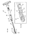
- FIGS. 3A and 3B are an isometric and a side exploded view, respectively, showing the components of the implant of FIG. 1A ;
- FIGS. 4A-4C are center-plane cross-sectional views taken through the implant of FIG. 1A in a minimum-angle, intermediate-angle and maximum-angle state, respectively;
- FIGS. 5A-5C are a sequence of schematic lateral views illustrating a process of restoration of lordotic angle between adjacent vertebral bodies using the implant of FIGS. 1A and 1B ;
- FIG. 6A is a schematic axial view illustrating introduction of the implant of FIG. 1A into an intervertebral space via a transforaminal approach;
- FIG. 6B is a view similar to FIG. 6A after deployment of the implant
- FIG. 7 is a schematic axial view illustrating a pair of implants as in FIG. 1A deployed bilaterally in an intervertebral space via a posterior approach;
- FIG. 8 is an isometric view of a variant of the implant of FIG. 1A suitable for intervertebral placement via an anterior or lateral approach;
- FIG. 9 is a schematic axial view illustrating placement of the implant of FIG. 8 within an intervertebral space
- FIG. 10 is a schematic lateral view illustrating deployment of the implant of FIG. 8 deployed within an intervertebral space via an anterior approach;
- FIGS. 11A and 11B are schematic isometric views of the implant of FIG. 8 held by a compression tool for deployment via a lateral approach, the implant being shown in a minimum-angle and an increased-angle state, respectively;
- FIG. 12A is a schematic axial view illustrating introduction of the implant of FIG. 1A into an intervertebral space via a transverse approach;
- FIG. 12B is a view similar to FIG. 12A after deployment of the implant
- FIGS. 13A-13C are a sequence of schematic anterior views illustrating a process of correcting a scoliosis misalignment between adjacent vertebral bodies using the implant of FIG. 1A ;
- FIGS. 14A-14C are isometric views of an implant, constructed and operative according to an embodiment of the present invention, with an adjustable angle between two tissue contact surfaces, the implant being shown in a minimum-angle, an increased-angle and a maximum-angle state, respectively;
- FIGS. 15A-15C are isometric views similar to FIGS. 14A-14C , respectively, cut-away along a center-plane of the implant;
- FIG. 16A is an isometric exploded view illustrating the components of the implant of FIG. 14A ;
- FIG. 16B is an enlarged view of the region of FIG. 16A designated XVI;
- FIG. 17A is a side view of the implant of FIG. 14B showing the implant in a partially raised state engaged by a deployment rod with an integrated ratchet release element effective to release locking of a ratchet configuration;
- FIG. 17B is a view similar to FIG. 17A during removal of the deployment rod, and showing the ratchet configuration engaged;
- FIGS. 18A and 18B are central-plane cross-sectional views taken through FIGS. 17A and 17B , respectively;
- FIG. 19A is an isometric view illustrating the implant of FIG. 14A attached to a delivery system
- FIG. 19B is an enlarged view of the region of FIG. 19A designated XIX;
- FIG. 20A is a center-plane cross-sectional view taken through the delivery system as illustrated in FIG. 19A ;
- FIG. 20B is an enlarged view of the region of FIG. 20A designated XX;
- FIG. 20C is an enlarged view of the region of FIG. 20A designated XXI;
- FIG. 21A is an isometric view of a variant of the implant of FIG. 14A-14C employing a keyhole slot for engagement of a deployment rod;
- FIG. 21B is an enlargement of a region of FIG. 21A designated XXI;
- FIG. 21C is an isometric view of a deployment rod for use with the implant of FIG. 21A including a keyhole slot engagement configuration and a cam-type ratchet mechanism release feature;
- FIGS. 22A-22C are central-plane cross-sectional views taken through the implant of FIG. 21A showing the deployment rod in a pre-engagement state, an engaged ratchet-release state and an engaged ratchet-engaged state, respectively;
- FIGS. 23A-23C are cross-sectional views taken along the plane XXIII shown in FIGS. 22A-22C , respectively;
- FIGS. 24A and 24B are side views of an implant according to a variant implementation of the implant of FIG. 14A illustrating a first alternative deployment of a linking segment, the implant being shown in a minimum angle and maximum angle state, respectively;
- FIGS. 25A and 25B are side views of an implant according to a further variant implementation of the implant of FIG. 14A illustrating a further alternative deployment of a linking segment, the implant being shown in a minimum angle and maximum angle state, respectively;
- FIGS. 26A and 26B are side views of an implant according to a still further variant implementation of the implant of FIG. 14A illustrating a further alternative deployment of a linking segment, the implant being shown in a minimum angle and maximum angle state, respectively.
- the present invention is an orthopedic implant with an adjustable angle between two tissue contact surfaces.
- FIGS. 1A-25B illustrate various embodiments of an implant, constructed and operative according to the teachings of an embodiment of the present invention.
- an implant for insertion between two regions of tissue, having a base 12 having a first contact surface 14 for contacting a first region of tissue.
- Base 12 includes a first portion 16 displaceable relative to a second portion 18 so that base 12 assuming an initial length, and is shortened towards a second length when first portion 16 is displaced towards second portion 18 .
- a hinged element 20 having a second contact surface 22 for contacting a second region of tissue, is interconnected with first portion 16 of base 12 at an effective hinge 24 .
- a linking segment 26 is hingedly connected to both second portion 18 of base 12 at a hinge 28 and to hinged element 20 at a hinge 30 .
- linking segment 26 is such that shortening of base 12 from its initial length towards its second length causes the linking segment to push a region of hinged element 20 away from base 12 , thereby changing an angle of second contact surface 22 relative to first contact surface 14 .
- the present invention provides a highly advantageous solution for adjusting the angular relation between tissue surfaces.
- the device is deployed in an intervertebral space and actuated to restore a desired degree of lordosis, or in some cases to generate a hyperlordotic adjustment, as will be discussed further below.
- the device may be oriented to allow adjustment of a lateral misalignment between vertebrae, such as for correction of a scoliosis misalignment.
- the device preferably provides a continuous, or near continuous, range of adjustment, typically spanning a range (from minimum angle to maximum angle) of at least 10 degrees. In some implementations, adjustments reaching angles in excess of 30 degrees may be provided.
- first and second portions 16 , 18 of base 12 which are explicitly referred to as being relatively movable, other subdivisions of the above components into subcomponents are most preferably rigidly interconnected such that they function mechanically as a single component.
- first portion 16 of base 12 is rigidly interconnected with a bridging portion 16 a which supports hinge 24
- hinged element 20 is formed from two elongated components interconnected by the pins of hinges 24 and 30 .
- the contact surfaces are typically not smooth surfaces, but rather are formed with various textures and/or tissue engaging features which facilitate anchoring of the device against the adjacent tissue surfaces, typically bone.
- the overall profile of the contact surface may have a curvature, such as a convex curvature to engage a corresponding concavity, for example, in a lumbar vertebral endplate.
- a plane of the contact surface for the purpose of defining angles thereto is defined by a best-fit plane over the entire contact surface, for example by minimizing a least-squares misfit, neglecting localized projecting features.
- contact surface 14 of base 12 this includes the parts of both first and second portions 16 and 18 that are disposed to contact adjacent tissue, but excludes relatively recessed intermediate portions which are not typically expected to come in contact with adjacent tissue.
- the angle between two contact surfaces is defined herein in the description and claims as the angle formed between the planes of the two contact surfaces when extrapolated to intersect, typically beyond the body of the implant. In a state in which the two contact surface planes are parallel, the angle between them is defined as zero. Where the end of hinged element 20 furthest from effective hinge 24 is initially closer to base 12 than the other end of hinged element 20 , such as in FIGS. 1A and 4A , the angle is defined as negative.
- the contact surfaces are typically not full surfaces but rather have various openings (apertures or spaces) which may be either enclosed or open-sided.
- the contact surface are partial surfaces having one or more openings totaling at least a quarter, and most preferably at least half, of a total area of a contact surface footprint.
- the “contact surface footprint” for this purpose is taken to be the region enclosed by the shortest line in the contact surface plane encompassing (the projections of) all parts of the contact surface.
- a length of the contact surface this refers to the largest dimension of the contact surface footprint, exemplified by dimension D 1 in FIG. 4B .
- the length of linking segment 26 this refers to a dimension of the linking segment between axes 28 , 30 of its hinged interconnection with base 12 and hinged element 20 , as exemplified by dimension D 2 in FIG. 4B .
- an “effective hinge” or “hinged interconnection” refers to both hinge joints, pivotal linkages and integral hinges which provide an effect similar to a single hinge over the relevant range of angular motion. It is a particular feature of certain preferred embodiments of the present invention that overall geometry of the axes, or effective axes, 24 , 28 and 30 remains effectively a rigid triangular form with one variable-length side which generates the required change in form, although a linkage or integral joint which defines an effective axis which lies outside the body of the implant and/or which moves somewhat during the adjustment also falls within the scope of this definition.
- any and all references to particular orientations of the devices of the present invention, to anatomical directions, or to motion of one component relative to another, are used merely for clarity of presentation, and do not limit the scope of the invention as claimed unless explicitly stated to the contrary.
- the devices may be used in any orientation including, for example, with “base 12 ” uppermost, and motion of first portion 16 towards second portion 18 typically refers to relative motion which may be achieved by moving either or both of the components in question.
- first portion 16 corresponds to the proximal portion and second portion 18 corresponds to the distal portion. This correspondence, however, is exemplary and should not be considered limiting. Reversed configurations also clearly fall within the scope of the present invention, for example, as illustrated with reference to an anterior approach implant in FIG. 10 .
- a wide range of implementations of the present invention may essentially be viewed as a rigid triangular configuration defined by the positions of axes, or effective axes, 24 , 28 and 30 , wherein shortening of one side of the triangle, corresponding to at least part of base 12 , causes a change in angle of hinged element 20 , associated with one of the other sides of the triangle, relative to the base.
- the specific positions of the axes, relative sizes of the sides, and geometrical forms of the contact surfaces relative to the underlying triangle may all vary considerably according to the intended application, the required range of angles, the expected loading, the available deployment forces, and the properties of the materials to be used.
- a partial set of examples of possible geometries is presented in the examples described herein.
- the contact surface length D 1 of hinged element 20 is at least 40% longer than the linking segment length D 2 , and in many cases 100% longer, i.e., where D 1 is at least twice D 2 .
- This ratio reflects the fact that hinged element 20 performs a function of supporting tissue whereas linking segment 26 provides only an internal mechanical support function, leading to asymmetry between elements 20 and 26 .
- a “fully raised” state of linking segment 26 corresponding to the fully shortened state of base 12 , has the axis-to-axis direction of linking segment 26 deployed at a steep angle, typically in excess of 70 degrees, to a plane of base 12 .
- the contact surface length D 1 of hinged element 20 is also typically at least 80% of the minimum length L 3 of base 12 , and in various cases, at least equal to L 3 .
- hinged connection 30 is located closely adjacent to (i.e., within 10% of the contact surface length from) the end of hinged element 20 furthest from effective hinge 24 . In various cases, it may be advantageous to place hinged connection 30 closer to effective hinge 24 , thereby typically achieving an increased range of angular adjustment for a given adjustment of the length of base 12 . For this reason, a preferred position of hinged connection 30 for certain implementations of the present invention is specifically distanced from the end of hinged element 20 by at least 10% of the contact surface length.
- hinged connection 30 is located between 10% and 30% of the contact surface length from the end.
- hinged connection 30 is located between 30% and 60% of the contact surface length from the end.
- hinged connection 30 is located between 50% and 80% of the contact surface length from the end furthest from effective hinge 24 .
- hinged connection 30 is located between 80% and 100% of the contact surface length from the end furthest from effective hinge 24 , while effective hinge 24 itself is moved closer to contact surface 14 of the base to ensure the required leverage to pivot hinged element 20 when the length of the base changes.
- the latter options facilitate achieving a given angular adjustment with much smaller relative motion between first and second portions 16 , 18 of base 12 and/or can achieve much greater ranges of angular adjustment, for example, providing angles up to in excess of 40 degrees for hyperlordotic correction where desired.
- the increased ratio of output angular motion subjects the components to significantly greater mechanical stress than the earlier embodiments, therefore requiring use of strong mechanical materials and/or more robust structural design.
- a typical, non-limiting example of material suitable for manufacturing various embodiments of the present invention, including such high-stress implants, is titanium.
- An additional material more suited for the lower-stress implementations is a biocompatible structural polymer, such as PEEK.
- Angular adjustment of the implants of the present invention is preferably achieved by shortening base 12 , i.e., by bringing first portion 16 and second portion 18 towards each other, referred to herein as “actuation”.
- actuation it is desired to maintain an angled state of the implant, typically at or near the final raised state which the implant achieved during adjustment. This is referred to herein as “locking”.
- the functions of actuation and locking may be performed by a single combined mechanism, or by separate mechanisms dedicated to each function, and such mechanisms may be either integrated into the implant structure or may be separate structures which are deployable within the implant prior to use and/or removable from the implant after use, as appropriate.
- a threaded actuator (not shown) may be deployed so as to link first and second portions 16 , 18 so that rotation of an actuator bolt, or of a tightening nut, is effective to apply force to bring the two portions together, thereby shortening base 12 .
- a threaded actuator with a suitably chosen thread pitch also achieves frictional locking, thereby maintaining any desired final angle of the device.
- a threaded actuator is particularly suited to high stress implementations such as implants 400 and 500 discussed above.
- a removable actuating mechanism is employed, most preferably integrated with a delivery system for positioning the implant within a body.
- a delivery system for positioning the implant within a body An example of such a system is illustrated in FIGS. 19A-20C .
- a preferred principle of operation for a removable actuation system employs a deployment rod 32 ( FIGS. 17A-18B and 20 A- 20 C) which is inserted via an opening 34 in a proximal end of the implant, here corresponding to first portion 16 , and engages a distal portion, here corresponding to second portion 18 .
- a force applied to a proximal end of the implant, in this case first portion 16 in a distal direction can be opposed by a counterforce applied via deployment rod 32 to second portion 18 , thereby causing shortening of base 12 .
- Engagement of a tip of deployment rod 32 with distal portion 18 may be by any suitable arrangement, such as via threaded engagement 36 , as illustrated in FIG. 18A , or by a pin 38 and keyhole-slot 40 arrangement, as illustrated in FIGS. 21A-21C .
- Application of actuating force is preferably achieved by use of an actuator mechanism built into a handle of a delivery system, such as that of FIGS. 19A-20C , which allows continuous and controllable adjustment of the relative displacement of first and second portions 16 , 18 .
- deployment rod 32 is preferably disengaged from second portion 18 and the deployment system is removed.
- the removable actuator structure is of particular value in interbody fusion applications, where the remaining inner volume of the implant is preferably contiguous with the aforementioned openings in the tissue contact surfaces to provide a through-channel for formation of a bone bridge between the vertebral endplates.
- Proximal opening 34 also allows for introduction and/or topping up of a filler material, such as natural or processed bone chips, medicaments and/or other fillers.
- FIGS. 19A-20C A non-limiting example of a delivery system, generally designated 60 , is illustrated in FIGS. 19A-20C .
- the delivery system preferably includes a forked gripping mechanism including a pair of jaws 62 with complementary engagement features configured to engage lateral gripping regions 64 of the implant (visible in FIG. 14A ). Jaws 62 are tightened against and released from engagement with implant 200 be advancing or retracting an outer sleeve 66 by rotation of a threaded collar 68 .
- Adjustment of the angle of contact surfaces of the implant is achieved by relative motion of jaws 62 pushing distally on first portion 16 while a counterforce is applied to second portion 18 via deployment rod 32 .
- An exemplary mechanism for generating these forces is illustrated in FIGS. 20A and 20C .
- rotation of a handle 70 causes rotation of an insert 72 which is locked against axial motion relative to an outer housing 74 , but is free to rotate.
- Insert 72 terminates at an internally threaded collar 76 which is engaged with a displacer element 78 which is mechanically restricted to axial motion within housing 74 .
- Displacer element 78 engages an actuator sleeve 80 which is mechanically linked to outer sleeve 66 and jaws 62 .
- Deployment rod 32 passes through the center of this entire assembly, and is fixed against axial displacement relative to housing 74 by a clamping element 82 which engages with a peripheral recess 84 in rod 32 .
- rotation of handle 70 is effective to advance displacer element 78 relative to deployment rod 32 , thereby applying the required forces via actuator sleeve 80 and jaws 62 to push proximal portion 16 towards distal portion 18 which is held by deployment rod 32 .
- an angle indicator 86 is associated with displacer element 78 so as to move relative to angle markings provided on housing 74 , thereby indicating to a medical practitioner the angle currently reached by the contact surfaces of the implant.
- a removable actuation system typically requires provision of a separate locking mechanism.
- a wide range of locking mechanisms may be used to implement the present invention, including but not limited to, insertion of various propping elements, pins or bolts to fix the relative positions of two or more element of the implant.
- One particularly preferred subset of implementations of the present invention employs a ratchet configuration to maintain a desired deployed state of the device.
- first portion 16 and second portion 18 are preferably formed with complementary features defining a ratchet configuration.
- the complementary features as illustrated here include a series of ratchet teeth 42 associated with proximal portion 16 and a resiliently biased detent 44 associate with distal portion 18 .
- the ratchet configuration is deployed to allow shortening of base 12 from its initial length through a range of lengths, and to oppose lengthening of the base.
- ratchet configuration is particularly advantageous in that it allows unrestricted adjustment of the implant angle during deployment, while ensuring that the deployed angle is maintained very close to the maximum angle after the deployment system is released.
- the spacing of the ratchet teeth defines the distance between locking positions, defining at least one, and preferably at least three, and more preferably at least six, sequential states in which the implant locks. In some cases, ten or more teeth may be used to achieve a quasi-continuous range of locking positions.
- the contact surfaces it is typically preferable for the contact surfaces to have large openings, preferably including a major central opening running along at least part of a length of contact surface 14 , which in some cases precludes central positioning of a ratchet configuration.
- particularly preferred implementations as illustrated herein employ a pair of ratchet arrangements deployed bilaterally, with a row of ratchet teeth 42 running along each side of a forked second portion 18 , and a corresponding pair of spaced-apart biased detents 44 on first portion 16 , as best seen in FIGS. 3A and 16A . This provides enhanced stability and rigidity to the deployed implant.
- ratchet configuration may be implemented in any orientation, and may arbitrarily be reversed between the proximal and distal portions.
- the series of ratchet teeth may be implemented as part of proximal portion 16 , and may face “upwards” towards hinged element 20 , “downwards” towards contact surface 14 , inwards towards the internal space of the implant, or outwards.
- ratchet teeth 42 may have a relatively steep rise surface but may avoid full locking that would be achieved by an upright or undercut surface. This case would allow the locking to be overcome by application of sufficient outward force to overcome the reverse resistance of the ratchet configuration. More preferably, however, the present invention provides a ratchet release mechanism which facilitates reversal of the angular deployment without requiring application of large forces, as will now be described.
- the ratchet and ratchet release mechanism described herein are applicable broadly to any adjustable implant in which adjustment is achieved by relative motion between two components which should normally be maintained at the displaced positions they reach at the end of the adjustment, but which must on occasion be released in order to readjust, reposition or remove the implant.
- Additional examples of implants in which such a mechanism may be used to advantage include, but are not limited to, adjustable dimension implants, such as expanding cages, with or without lordotic correction.
- FIGS. 16A and 16B One particularly preferred but non-limiting example of a ratchet release mechanism is illustrated in FIGS. 16A and 16B .
- a crossbar 46 is mechanically linked to detents 44 so that upward displacement of crossbar 46 (in the orientation illustrated here) is effective to flex the resilient support structure and raise detents 44 out of engagement with ratchet teeth 42 .
- Disengagement of the ratchet configuration can thus be achieved by insertion of a suitably formed ratchet release element via proximal opening 34 so as to bear against crossbar 46 and release engagement of detents 44 with ratchet teeth 42 , thereby allowing lengthening of base 12 .
- this “ratchet release element” is integrated as part of deployment rod 32 .
- an engagement of deployment rod 32 with the distal portion of base 12 in this case, second portion 18 , is configured to allow a first motion of the deployment rod while maintaining engagement of deployment rod 32 with the distal portion.
- Deployment rod 32 is provided with at least one feature deployed such that this first motion is effective to bring the at least one feature to bear on crossbar 46 , thereby releasing engagement of detent(s) 44 with the ratchet teeth 42 to allow lengthening of the base.
- FIGS. 17A-18B A first implementation of these features is further illustrated in FIGS. 17A-18B .
- the threaded engagement 36 between deployment rod 32 and second portion 18 allows a range of axial positions, depending upon the number of axial rotations of deployment rod 32 used to engage the threaded engagement.
- Deployment rod 32 here features an outward step 48 which is positioned such that, in a first axial position ( FIG. 18A ), when fully engaged with the threaded engagement 36 , outward step 48 bears against crossbar 46 , flexing it “upwards” as shown, thereby disengaging detents 44 from ratchet teeth 42 as shown in FIG. 17A .
- a second axial position FIG.
- FIGS. 21A-23C An alternative implementation is illustrated in FIGS. 21A-23C in which engagement between deployment rod 32 and distal (second) portion 18 is achieved through lateral pin 38 engaging a bayonet slot with a keyhole opening 40 .
- deployment rod 32 here assumes a first position with pin 38 upwards ( FIG. 23A ) in which the rod can be freely inserted and removed via keyhole opening 40 , a first rotated position ( FIG. 23B ), rotated anticlockwise 90 degrees, in which pin 38 is already locked within the bayonet slot, and a second rotated position ( FIG. 23C ), rotated 180 degrees anticlockwise.
- FIG. 23A first position with pin 38 upwards
- FIG. 23B first rotated position
- FIG. 23C rotated anticlockwise 90 degrees
- FIG. 23C second rotated position
- a region of deployment rod 32 positioned to come into alignment with crossbar 46 is provided with an eccentric cam surface 50 , shown in this example with its maximum radius roughly opposite pin 38 .
- rotation of deployment rod 32 from its first rotated position to its second rotated position is effective to bring cam surface 50 to bear on crossbar 46 , thereby lifting detents 44 out of engagement with ratchet teeth 42 .
- the ratchet arrangement may provide audible and/or tactile feedback during the adjustment process which may be helpful to the medical practitioner. Further motion of deployment rod in order to release the ratchet mechanism would then only be performed in the event that readjusting, repositioning or removal of the implant becomes necessary.
- the ratchet-release state may be used as the default state during deployment. In all cases, reengagement of the ratchet preferably occurs as part of the disengagement process, and prior to complete disengagement of deployment rod 32 from the distal portion, thereby helping to ensure that any forces acting on the implant do not disturb the intended adjusted state of the implant.
- Implants of the present invention may be employed in a wide range of applications in which it is desired to adjust the relative angular deployment of two regions of tissue.
- the invention is illustrated herein primarily in the context of various intervertebral applications.
- the implant 10 (or 52 , 200 , 300 , 400 or 500 ) is introduced between two vertebral bodies 900 , 902 such that first contact surface 14 contacts an endplate of a first of the vertebral bodies 900 and second contact surface 22 contacts an endplate of a second of the vertebral bodies 902 .
- Relative motion of first and second portions 16 , 18 of base 12 is then used to actuate a change in angle between the contact surfaces, thereby changing an angle between the endplates.
- FIGS. 5A-5C are representative of a transforaminal or posterior approach, where the implant is used for lordotic correction to restore or increase an angle of lordosis between adjacent vertebral bodies, for example, as part of a transforaminal or posterior lumbar interbody fusion (TLIF or PLIF) procedure.
- FIG. 5A illustrates introduction of the implant.
- the placement of the deployed implant is illustrated in FIG. 5B , prior to adjustment, and in FIG. 5C after restoration of a lordotic angle.
- FIGS. 6A and 6B illustrate schematically in plan view the deployment and final placement of implant 10 (or the other embodiments described herein) via a transforaminal approach.
- FIG. 7 illustrates the final deployment via a posterior approach.
- bilateral use of a pair of implants is illustrated, where both implants contribute to the angular correction between the vertebral bodies.
- Use of more than one implant is encompassed within the scope of the invention also for transforaminal, lateral and other approaches.
- the dimensions and proportions of the implant can readily be adapted according to the intended application and the available access route.
- it may be preferably to employ a single, anatomically shaped implant 52 sized to occupy a majority of the dimensions of the vertebral body endplates.
- second portion 18 becomes the proximal end of base 12 relative to the anterior direction of approach, and the proximal opening 34 in this case traverses second portion 18 and/or connecting segment 26 .
- Fixation of implant 52 may optionally be enhanced by insertion of anteriorly placed bone screws 54 , as illustrated in FIG. 10 .
- Implant 52 may also be introduced via a lateral approach.
- gripping and actuation of the implant adjustment is typically performed via a laterally-engaged compression tool 56 , as depicted schematically in FIGS. 11A and 11B .
- FIGS. 12A-13C illustrate the use of a suitably sized implementation of implant 10 to correct a scoliosis misalignment between adjacent vertebral bodies.
- FIG. 12A-12B a lateral approach is shown, thereby aligning the implant so that the angular correction occurs in a lateral direction.
- implant and delivery system similar to that illustrated in FIGS. 11A and 11B could be introduced via an anterior approach to achieve adjustment of lateral alignment deflection.
- the endpoint of the adjustment in this case is typically roughly a zero angle inclination, so an implant implementation with a relatively small range of angular adjustment is typically sufficient.
- the actual adjustment state of the implant chosen by a medical practitioner in a clinical setting to achieve a desired alignment correction may vary considerably.
Abstract
Description
Claims (13)
Priority Applications (1)
| Application Number | Priority Date | Filing Date | Title |
|---|---|---|---|
| US14/178,328 US9005291B2 (en) | 2013-07-09 | 2014-02-12 | Orthopedic implant with adjustable angle between tissue contact surfaces |
Applications Claiming Priority (4)
| Application Number | Priority Date | Filing Date | Title |
|---|---|---|---|
| US201361843957P | 2013-07-09 | 2013-07-09 | |
| US201361897898P | 2013-10-31 | 2013-10-31 | |
| US14/165,614 US10149770B2 (en) | 2013-07-09 | 2014-01-28 | Orthopedic implant with adjustable angle between tissue contact surfaces |
| US14/178,328 US9005291B2 (en) | 2013-07-09 | 2014-02-12 | Orthopedic implant with adjustable angle between tissue contact surfaces |
Related Parent Applications (1)
| Application Number | Title | Priority Date | Filing Date |
|---|---|---|---|
| US14/165,614 Continuation US10149770B2 (en) | 2013-07-09 | 2014-01-28 | Orthopedic implant with adjustable angle between tissue contact surfaces |
Publications (2)
| Publication Number | Publication Date |
|---|---|
| US20150018954A1 US20150018954A1 (en) | 2015-01-15 |
| US9005291B2 true US9005291B2 (en) | 2015-04-14 |
Family
ID=52277727
Family Applications (2)
| Application Number | Title | Priority Date | Filing Date |
|---|---|---|---|
| US14/165,614 Active 2035-03-09 US10149770B2 (en) | 2013-07-09 | 2014-01-28 | Orthopedic implant with adjustable angle between tissue contact surfaces |
| US14/178,328 Active US9005291B2 (en) | 2013-07-09 | 2014-02-12 | Orthopedic implant with adjustable angle between tissue contact surfaces |
Family Applications Before (1)
| Application Number | Title | Priority Date | Filing Date |
|---|---|---|---|
| US14/165,614 Active 2035-03-09 US10149770B2 (en) | 2013-07-09 | 2014-01-28 | Orthopedic implant with adjustable angle between tissue contact surfaces |
Country Status (6)
| Country | Link |
|---|---|
| US (2) | US10149770B2 (en) |
| EP (1) | EP3019124B1 (en) |
| JP (1) | JP6493989B2 (en) |
| CN (1) | CN105324092A (en) |
| ES (1) | ES2750606T3 (en) |
| WO (1) | WO2015004660A1 (en) |
Cited By (56)
| Publication number | Priority date | Publication date | Assignee | Title |
|---|---|---|---|---|
| US20150018951A1 (en) * | 2013-07-09 | 2015-01-15 | Nlt Spine Ltd. | Orthopedic Implant with Adjustable Angle between Tissue Contact Surfaces |
| US9295562B2 (en) | 2008-01-17 | 2016-03-29 | DePuy Synthes Products, Inc. | Expandable intervertebral implant and associated method of manufacturing the same |
| US9320615B2 (en) | 2010-06-29 | 2016-04-26 | DePuy Synthes Products, Inc. | Distractible intervertebral implant |
| US9526620B2 (en) | 2009-03-30 | 2016-12-27 | DePuy Synthes Products, Inc. | Zero profile spinal fusion cage |
| US9532884B2 (en) | 2011-07-14 | 2017-01-03 | Nlt Spine Ltd. | Laterally deflectable implant |
| US9561117B2 (en) | 2012-07-26 | 2017-02-07 | DePuy Synthes Products, Inc. | Expandable implant |
| US9717601B2 (en) | 2013-02-28 | 2017-08-01 | DePuy Synthes Products, Inc. | Expandable intervertebral implant, system, kit and method |
| US9750552B2 (en) | 2009-07-06 | 2017-09-05 | DePuy Synthes Products, Inc. | Expandable fixation assemblies |
| US9820865B2 (en) | 2013-10-31 | 2017-11-21 | Nlt Spine Ltd. | Adjustable implant |
| US9913727B2 (en) | 2015-07-02 | 2018-03-13 | Medos International Sarl | Expandable implant |
| US9962272B1 (en) | 2017-06-28 | 2018-05-08 | Amendia, Inc. | Intervertebral implant device with lordotic expansion |
| US9993349B2 (en) | 2002-06-27 | 2018-06-12 | DePuy Synthes Products, Inc. | Intervertebral disc |
| US10085849B2 (en) | 2010-09-03 | 2018-10-02 | Globus Medical, Inc. | Expandable fusion device and method of installation thereof |
| US10159582B2 (en) | 2011-09-16 | 2018-12-25 | DePuy Synthes Products, Inc. | Removable, bone-securing cover plate for intervertebral fusion cage |
| US10369015B2 (en) | 2010-09-23 | 2019-08-06 | DePuy Synthes Products, Inc. | Implant inserter having a laterally-extending dovetail engagement feature |
| US10398563B2 (en) | 2017-05-08 | 2019-09-03 | Medos International Sarl | Expandable cage |
| US20190274846A1 (en) * | 2013-12-23 | 2019-09-12 | Jmea Corporation | Devices And Methods For Preparation Of Vertebral Members |
| US10512550B2 (en) | 2010-09-03 | 2019-12-24 | Globus Medical, Inc. | Expandable interspinous process fixation device |
| US10537436B2 (en) | 2016-11-01 | 2020-01-21 | DePuy Synthes Products, Inc. | Curved expandable cage |
| US10709573B2 (en) | 2010-09-03 | 2020-07-14 | Globus Medical Inc. | Expandable fusion device and method of installation thereof |
| US10758367B2 (en) | 2010-09-03 | 2020-09-01 | Globus Medical Inc. | Expandable fusion device and method of installation thereof |
| US10779957B2 (en) | 2010-09-03 | 2020-09-22 | Globus Medical, Inc. | Expandable fusion device and method of installation thereof |
| US10835387B2 (en) | 2010-09-03 | 2020-11-17 | Globus Medical Inc. | Expandable fusion device and method of installation thereof |
| US10842644B2 (en) | 2010-09-03 | 2020-11-24 | Globus Medical, Inc. | Expandable fusion device and method of installation thereof |
| US10869768B2 (en) | 2010-09-03 | 2020-12-22 | Globus Medical Inc. | Expandable fusion device and method of installation thereof |
| US10881518B2 (en) | 2017-04-01 | 2021-01-05 | HD LifeSciences LLC | Anisotropic biocompatible lattice structure |
| US10888433B2 (en) | 2016-12-14 | 2021-01-12 | DePuy Synthes Products, Inc. | Intervertebral implant inserter and related methods |
| US10940016B2 (en) | 2017-07-05 | 2021-03-09 | Medos International Sarl | Expandable intervertebral fusion cage |
| US10945858B2 (en) | 2010-09-03 | 2021-03-16 | Globus Medical, Inc. | Expandable interspinous process fixation device |
| US10966840B2 (en) | 2010-06-24 | 2021-04-06 | DePuy Synthes Products, Inc. | Enhanced cage insertion assembly |
| US10973650B2 (en) | 2015-12-30 | 2021-04-13 | Nuvasive, Inc. | Lordotic expandable fusion implant |
| US20210205095A1 (en) * | 2014-08-12 | 2021-07-08 | Paul E. Kraemer | Spinal Fusion Apparatus |
| US20220000631A1 (en) * | 2013-03-07 | 2022-01-06 | DePuy Synthes Products, Inc. | Intervertebral implant |
| US11219532B2 (en) * | 2017-09-18 | 2022-01-11 | Loubert S. Suddaby | Stand-alone expandable interbody spinal fusion device with locking mechanism |
| US11234833B2 (en) | 2015-05-12 | 2022-02-01 | Nuvasive, Inc. | Expandable lordosis intervertebral implants |
| US11253368B2 (en) | 2017-02-14 | 2022-02-22 | Nanohive Medical Llc | Methods of designing high x-ray lucency lattice structures |
| US11273047B2 (en) | 2017-12-18 | 2022-03-15 | Nuvasive, Inc. | Expandable implant device |
| US11291558B2 (en) | 2018-07-26 | 2022-04-05 | Nanohive Medical Llc | Dynamic implant fixation plate |
| US11344424B2 (en) | 2017-06-14 | 2022-05-31 | Medos International Sarl | Expandable intervertebral implant and related methods |
| US11426290B2 (en) | 2015-03-06 | 2022-08-30 | DePuy Synthes Products, Inc. | Expandable intervertebral implant, system, kit and method |
| US11426286B2 (en) | 2020-03-06 | 2022-08-30 | Eit Emerging Implant Technologies Gmbh | Expandable intervertebral implant |
| US11446156B2 (en) | 2018-10-25 | 2022-09-20 | Medos International Sarl | Expandable intervertebral implant, inserter instrument, and related methods |
| US11446162B2 (en) | 2010-09-03 | 2022-09-20 | Globus Medical, Inc. | Expandable fusion device and method of installation thereof |
| US11452607B2 (en) | 2010-10-11 | 2022-09-27 | DePuy Synthes Products, Inc. | Expandable interspinous process spacer implant |
| US11497617B2 (en) | 2019-01-16 | 2022-11-15 | Nanohive Medical Llc | Variable depth implants |
| US11497618B2 (en) | 2006-12-07 | 2022-11-15 | DePuy Synthes Products, Inc. | Intervertebral implant |
| US11510788B2 (en) | 2016-06-28 | 2022-11-29 | Eit Emerging Implant Technologies Gmbh | Expandable, angularly adjustable intervertebral cages |
| US11596522B2 (en) | 2016-06-28 | 2023-03-07 | Eit Emerging Implant Technologies Gmbh | Expandable and angularly adjustable intervertebral cages with articulating joint |
| US11617655B2 (en) | 2008-04-05 | 2023-04-04 | DePuy Synthes Products, Inc. | Expandable intervertebral implant |
| US11622868B2 (en) | 2007-06-26 | 2023-04-11 | DePuy Synthes Products, Inc. | Highly lordosed fusion cage |
| US11679000B2 (en) | 2013-05-22 | 2023-06-20 | Nuvasive, Inc. | Expandable fusion implant and related methods |
| US11684485B1 (en) * | 2020-02-04 | 2023-06-27 | Guillermo Molina | Surgically implantable joint spacer |
| US11752009B2 (en) | 2021-04-06 | 2023-09-12 | Medos International Sarl | Expandable intervertebral fusion cage |
| US11793654B2 (en) | 2010-09-03 | 2023-10-24 | Globus Medical, Inc. | Expandable fusion device and method of installation thereof |
| US11850160B2 (en) | 2021-03-26 | 2023-12-26 | Medos International Sarl | Expandable lordotic intervertebral fusion cage |
| US11931266B2 (en) | 2016-06-07 | 2024-03-19 | Nanohive Medical Llc | Implant with independent endplates |
Families Citing this family (48)
| Publication number | Priority date | Publication date | Assignee | Title |
|---|---|---|---|---|
| US8597360B2 (en) | 2004-11-03 | 2013-12-03 | Neuropro Technologies, Inc. | Bone fusion device |
| US8540452B2 (en) | 2008-12-31 | 2013-09-24 | Spinex Tec, Llc | Flexible joint arrangement incorporating flexure members |
| US8628577B1 (en) | 2009-03-19 | 2014-01-14 | Ex Technology, Llc | Stable device for intervertebral distraction and fusion |
| US8287597B1 (en) | 2009-04-16 | 2012-10-16 | Nuvasive, Inc. | Method and apparatus for performing spine surgery |
| US8608785B2 (en) | 2010-06-02 | 2013-12-17 | Wright Medical Technology, Inc. | Hammer toe implant with expansion portion for retrograde approach |
| US9498273B2 (en) | 2010-06-02 | 2016-11-22 | Wright Medical Technology, Inc. | Orthopedic implant kit |
| US9724140B2 (en) | 2010-06-02 | 2017-08-08 | Wright Medical Technology, Inc. | Tapered, cylindrical cruciform hammer toe implant and method |
| DE102010047901B4 (en) * | 2010-10-11 | 2019-01-10 | Heinrich Böhm | Implant for the spine and operating instrument |
| US9308099B2 (en) | 2011-02-14 | 2016-04-12 | Imds Llc | Expandable intervertebral implants and instruments |
| WO2013023098A1 (en) | 2011-08-09 | 2013-02-14 | Neuropro Spinal Jaxx Inc. | Bone fusion device, apparatus and method |
| WO2013023096A1 (en) | 2011-08-09 | 2013-02-14 | Neuropro Technologies, Inc. | Bone fusion device, system and method |
| US10420654B2 (en) | 2011-08-09 | 2019-09-24 | Neuropro Technologies, Inc. | Bone fusion device, system and method |
| US10159583B2 (en) * | 2012-04-13 | 2018-12-25 | Neuropro Technologies, Inc. | Bone fusion device |
| US9532883B2 (en) | 2012-04-13 | 2017-01-03 | Neuropro Technologies, Inc. | Bone fusion device |
| US8945232B2 (en) | 2012-12-31 | 2015-02-03 | Wright Medical Technology, Inc. | Ball and socket implants for correction of hammer toes and claw toes |
| US10098757B2 (en) | 2013-03-15 | 2018-10-16 | Neuropro Technologies Inc. | Bodiless bone fusion device, apparatus and method |
| US9724139B2 (en) | 2013-10-01 | 2017-08-08 | Wright Medical Technology, Inc. | Hammer toe implant and method |
| US9474561B2 (en) | 2013-11-19 | 2016-10-25 | Wright Medical Technology, Inc. | Two-wire technique for installing hammertoe implant |
| US9545274B2 (en) * | 2014-02-12 | 2017-01-17 | Wright Medical Technology, Inc. | Intramedullary implant, system, and method for inserting an implant into a bone |
| US9498266B2 (en) | 2014-02-12 | 2016-11-22 | Wright Medical Technology, Inc. | Intramedullary implant, system, and method for inserting an implant into a bone |
| US9486328B2 (en) * | 2014-04-01 | 2016-11-08 | Ex Technology, Llc | Expandable intervertebral cage |
| WO2016043751A1 (en) | 2014-09-18 | 2016-03-24 | Wright Medical Technology, Inc. | Hammertoe implant and instrument |
| JP6438033B2 (en) | 2014-12-19 | 2018-12-12 | ライト メディカル テクノロジー インコーポレイテッドWright Medical Technology, Inc. | Intramedullary implant |
| US9814602B2 (en) * | 2015-05-14 | 2017-11-14 | Globus Medical, Inc. | Expandable intervertebral implants and methods of installation thereof |
| US10500061B2 (en) * | 2015-08-13 | 2019-12-10 | K2M, Inc. | Adjustable spinal implant |
| US10105238B2 (en) | 2015-08-25 | 2018-10-23 | Imds Llc | Expandable intervertebral implants |
| US10610376B2 (en) | 2015-10-16 | 2020-04-07 | Warsaw Orthopedic, Inc. | Expandable spinal implant system and method |
| US9937054B2 (en) * | 2016-01-28 | 2018-04-10 | Warsaw Orthopedic, Inc. | Expandable implant and insertion tool |
| US10137006B2 (en) * | 2016-01-28 | 2018-11-27 | Warsaw Orthopedic, Inc. | Geared cam expandable interbody implant and method of implanting same |
| US9974662B2 (en) * | 2016-06-29 | 2018-05-22 | Globus Medical, Inc. | Expandable fusion device and method of installation thereof |
| US10052215B2 (en) * | 2016-06-29 | 2018-08-21 | Globus Medical, Inc. | Expandable fusion device and method of installation thereof |
| WO2018081322A1 (en) | 2016-10-25 | 2018-05-03 | Imds Llc | Methods and instrumentation for intervertebral cage expansion |
| FR3058044A1 (en) * | 2016-10-27 | 2018-05-04 | Ldr Medical | EXPANDABLE INTERSOMATIC CAGE |
| FR3058043B1 (en) * | 2016-10-27 | 2020-11-13 | Ldr Medical | EXPANDABLE INTERSOMATIC CAGE |
| US10238503B2 (en) | 2016-11-01 | 2019-03-26 | Warsaw Orthopedic, Inc. | Expandable spinal implant system with a biased tip and method of using same |
| US10111760B2 (en) | 2017-01-18 | 2018-10-30 | Neuropro Technologies, Inc. | Bone fusion system, device and method including a measuring mechanism |
| US10973657B2 (en) | 2017-01-18 | 2021-04-13 | Neuropro Technologies, Inc. | Bone fusion surgical system and method |
| US10213321B2 (en) | 2017-01-18 | 2019-02-26 | Neuropro Technologies, Inc. | Bone fusion system, device and method including delivery apparatus |
| US10729560B2 (en) | 2017-01-18 | 2020-08-04 | Neuropro Technologies, Inc. | Bone fusion system, device and method including an insertion instrument |
| USD946152S1 (en) * | 2020-11-06 | 2022-03-15 | Mirus Llc | Medical device |
| USD946151S1 (en) * | 2020-11-06 | 2022-03-15 | Mirus Llc | Medical device |
| US10709569B2 (en) * | 2017-11-09 | 2020-07-14 | Globus Medical, Inc. | Expandable intervertebral implant |
| US10722379B2 (en) | 2017-11-09 | 2020-07-28 | Globus Medical, Inc. | Expandable intervertebral implant |
| US10945859B2 (en) | 2018-01-29 | 2021-03-16 | Amplify Surgical, Inc. | Expanding fusion cages |
| JP6827080B2 (en) * | 2018-08-29 | 2021-02-10 | グローバス メディカル インコーポレイティッド | Expandable facet implant |
| US11497622B2 (en) | 2019-03-05 | 2022-11-15 | Ex Technology, Llc | Transversely expandable minimally invasive intervertebral cage and insertion and extraction device |
| US11234835B2 (en) | 2019-03-05 | 2022-02-01 | Octagon Spine Llc | Transversely expandable minimally invasive intervertebral cage |
| WO2021163708A1 (en) * | 2020-02-13 | 2021-08-19 | Nexus Spine, LLC | Deployable ramped nose for implantable medical devices |
Citations (109)
| Publication number | Priority date | Publication date | Assignee | Title |
|---|---|---|---|---|
| DE2263842A1 (en) | 1972-12-28 | 1974-07-04 | Hoffmann Daimler Siegfried Dr | DISC PROTHESIS |
| US4759769A (en) | 1987-02-12 | 1988-07-26 | Health & Research Services Inc. | Artificial spinal disc |
| DE9107494U1 (en) | 1991-06-18 | 1991-09-19 | Weber, Gerhard, 7238 Oberndorf, De | |
| US5059193A (en) | 1989-11-20 | 1991-10-22 | Spine-Tech, Inc. | Expandable spinal implant and surgical method |
| US5171278A (en) | 1991-02-22 | 1992-12-15 | Madhavan Pisharodi | Middle expandable intervertebral disk implants |
| US5258031A (en) | 1992-01-06 | 1993-11-02 | Danek Medical | Intervertebral disk arthroplasty |
| US5390683A (en) | 1991-02-22 | 1995-02-21 | Pisharodi; Madhavan | Spinal implantation methods utilizing a middle expandable implant |
| DE4416605C1 (en) | 1994-05-11 | 1995-06-08 | Aesculap Ag | Inter-vertebral implant |
| FR2717068B1 (en) | 1994-03-14 | 1996-04-26 | Biomat | Vertebral interbody fusion cage. |
| US5534029A (en) | 1992-12-14 | 1996-07-09 | Yumiko Shima | Articulated vertebral body spacer |
| US5599279A (en) | 1994-03-16 | 1997-02-04 | Gus J. Slotman | Surgical instruments and method useful for endoscopic spinal procedures |
| US5620458A (en) | 1994-03-16 | 1997-04-15 | United States Surgical Corporation | Surgical instruments useful for endoscopic spinal procedures |
| WO1998034552A1 (en) | 1997-02-06 | 1998-08-13 | Surgical Dynamics | Expandable non-threaded spinal fusion device |
| US6039761A (en) | 1997-02-12 | 2000-03-21 | Li Medical Technologies, Inc. | Intervertebral spacer and tool and method for emplacement thereof |
| US6080193A (en) | 1997-05-01 | 2000-06-27 | Spinal Concepts, Inc. | Adjustable height fusion device |
| US6126689A (en) | 1998-06-15 | 2000-10-03 | Expanding Concepts, L.L.C. | Collapsible and expandable interbody fusion device |
| US6190414B1 (en) | 1996-10-31 | 2001-02-20 | Surgical Dynamics Inc. | Apparatus for fusion of adjacent bone structures |
| US6238403B1 (en) | 1999-10-04 | 2001-05-29 | Microvention, Inc. | Filamentous embolic device with expansible elements |
| US6332894B1 (en) | 2000-03-07 | 2001-12-25 | Zimmer, Inc. | Polymer filled spinal fusion cage |
| US6375682B1 (en) | 2001-08-06 | 2002-04-23 | Lewis W. Fleischmann | Collapsible, rotatable and expandable spinal hydraulic prosthetic device |
| US6419705B1 (en) | 1999-06-23 | 2002-07-16 | Sulzer Spine-Tech Inc. | Expandable fusion device and method |
| US6443989B1 (en) | 2000-12-04 | 2002-09-03 | Roger P. Jackson | Posterior expandable fusion cage |
| US20020151976A1 (en) * | 1998-10-29 | 2002-10-17 | Kevin Foley | Expandable intervertebral spacers |
| US6491724B1 (en) * | 1999-08-13 | 2002-12-10 | Bret Ferree | Spinal fusion cage with lordosis correction |
| WO2003003951A1 (en) | 2001-07-02 | 2003-01-16 | Surgicraft Limited | Collapsible and expandable instrument for insertion in a dorsal vertebra |
| US6582451B1 (en) | 1999-03-16 | 2003-06-24 | The University Of Sydney | Device for use in surgery |
| US6620196B1 (en) | 2000-08-30 | 2003-09-16 | Sdgi Holdings, Inc. | Intervertebral disc nucleus implants and methods |
| WO2003005276A3 (en) | 2001-07-06 | 2003-10-23 | Lightsurf Technologies Inc | System and methodology for optimizing delivery of e-mail attachments for disparate devices |
| US6641614B1 (en) | 1997-05-01 | 2003-11-04 | Spinal Concepts, Inc. | Multi-variable-height fusion device |
| US20030236520A1 (en) | 2002-06-25 | 2003-12-25 | Roy Lim | Minimally invasive expanding spacer and method |
| US6676665B2 (en) | 2000-08-11 | 2004-01-13 | Sdgi Holdings, Inc. | Surgical instrumentation and method for treatment of the spine |
| US20040059418A1 (en) | 2002-09-18 | 2004-03-25 | Mckay William F. | Natural tissue devices and methods of implantation |
| US20040133280A1 (en) | 2002-11-21 | 2004-07-08 | Trieu Hai H. | Systems and techniques for interbody spinal stabilization with expandable devices |
| US20040193158A1 (en) | 2002-06-25 | 2004-09-30 | Roy Lim | Minimally invasive expanding spacer and method |
| US20050143827A1 (en) | 1999-01-27 | 2005-06-30 | Disco-O-Tech Medical Technologies Ltd. | Expandable intervertebral spacer |
| US20050182416A1 (en) | 2004-02-13 | 2005-08-18 | Roy Lim | Spacer with height and angle adjustments for spacing vertebral members |
| US20050228391A1 (en) | 2004-04-05 | 2005-10-13 | Levy Mark M | Expandable bone device |
| US20050278036A1 (en) | 2004-06-09 | 2005-12-15 | Ceravic | Method for restoration of human or animal bone anatomy, and expansible prosthetic implant allowing implementation of this method |
| US20060041258A1 (en) | 2004-08-19 | 2006-02-23 | Foster-Miller, Inc. | Support system for intervertebral fusion |
| US20060085070A1 (en) | 2004-10-20 | 2006-04-20 | Vertiflex, Inc. | Systems and methods for posterior dynamic stabilization of the spine |
| US20060142858A1 (en) | 2004-12-16 | 2006-06-29 | Dennis Colleran | Expandable implants for spinal disc replacement |
| US20060224241A1 (en) | 2005-03-31 | 2006-10-05 | Life Spine, Llc | Expandable spinal interbody and intravertebral body devices |
| US20060235423A1 (en) | 2005-04-01 | 2006-10-19 | Cantu Alberto R | Apparatus having at least one actuatable planar surface and method using the same for a spinal procedure |
| US20060247778A1 (en) | 2005-01-26 | 2006-11-02 | Ferree Bret A | Intradiscal devices including spacers facilitating posterior-lateral and other insertion approaches |
| US20070032791A1 (en) | 2005-07-14 | 2007-02-08 | Greenhalgh E S | Expandable support device and method of use |
| US20070123986A1 (en) | 2005-08-16 | 2007-05-31 | Laurent Schaller | Methods of Distracting Tissue Layers of the Human Spine |
| WO2007073584A1 (en) | 2005-12-29 | 2007-07-05 | Ozmiz Pty. Ltd. | Method and system for displaying data on a mobile terminal |
| US20070173939A1 (en) | 2005-12-23 | 2007-07-26 | The Board Of Trustees Of The Leland Stanford Junior University | Systems and methods for fixation of bone with an expandable device |
| US20070233245A1 (en) | 2006-03-31 | 2007-10-04 | Sdgi Holdings, Inc. | Methods and instruments for delivering intervertebral devices |
| WO2008084479A2 (en) | 2007-01-09 | 2008-07-17 | Nonlinear Technologies Ltd. | Devices for forming curved or closed-loop structures |
| US20080243255A1 (en) | 2007-03-29 | 2008-10-02 | Butler Michael S | Radially expandable spinal interbody device and implantation tool |
| US7431735B2 (en) | 1998-08-28 | 2008-10-07 | Sofamor S.N.C. | Expandable interbody fusion cage |
| US20080312743A1 (en) | 2007-06-15 | 2008-12-18 | Thierry Vila | Nucleus Prostheses |
| WO2009073918A2 (en) | 2007-12-10 | 2009-06-18 | Cellixe Pty Ltd | Agent delivery device and method |
| US20090216274A1 (en) | 2008-02-21 | 2009-08-27 | Zimmer Gmbh | Expandable interspinous process spacer with lateral support and method for implantation |
| US20090240334A1 (en) | 2008-03-19 | 2009-09-24 | Richelsoph Marc E | Vertebral device for restoration of vertebral body height |
| US20090270873A1 (en) | 2008-04-24 | 2009-10-29 | Fabian Henry F | Spine surgery method and inserter |
| US7655046B2 (en) | 2005-01-20 | 2010-02-02 | Warsaw Orthopedic, Inc. | Expandable spinal fusion cage and associated instrumentation |
| US7720282B2 (en) | 2005-08-02 | 2010-05-18 | Microsoft Corporation | Stereo image segmentation |
| US20100131009A1 (en) | 2008-11-19 | 2010-05-27 | Christian Roebling | Spinous process implant spacer and method of use therefor |
| US20100194753A1 (en) | 2000-08-07 | 2010-08-05 | Robotham John S | Device-Specific Content Versioning |
| US7799081B2 (en) | 2004-09-14 | 2010-09-21 | Aeolin, Llc | System and method for spinal fusion |
| US20100286787A1 (en) | 2006-04-12 | 2010-11-11 | Spinalmotion, Inc. | Posterior Spinal Device and Method |
| US7901409B2 (en) | 2006-01-20 | 2011-03-08 | Canaveral Villegas Living Trust | Intramedullar devices and methods to reduce and/or fix damaged bone |
| US7909872B2 (en) | 2005-06-03 | 2011-03-22 | Zipnick Richard I | Minimally invasive apparatus to manipulate and revitalize spinal column disc |
| US7938860B2 (en) | 2000-08-30 | 2011-05-10 | Warsaw Orthopedic, Inc. | Intervertebral disc nucleus implants and methods |
| US7947078B2 (en) | 2007-01-09 | 2011-05-24 | Nonlinear Technologies Ltd. | Devices for forming curved or closed-loop structures |
| US7959652B2 (en) | 2005-04-18 | 2011-06-14 | Kyphon Sarl | Interspinous process implant having deployable wings and method of implantation |
| US8021429B2 (en) | 2007-03-08 | 2011-09-20 | Zimmer Spine, Inc. | Deployable segmented TLIF device |
| US8025697B2 (en) | 2006-09-21 | 2011-09-27 | Custom Spine, Inc. | Articulating interbody spacer, vertebral body replacement |
| US8062375B2 (en) | 2009-10-15 | 2011-11-22 | Globus Medical, Inc. | Expandable fusion device and method of installation thereof |
| US20110319997A1 (en) | 2010-06-25 | 2011-12-29 | Chad Glerum | Expandable Fusion Device and Method of Installation Thereof |
| US20120004732A1 (en) | 2009-03-13 | 2012-01-05 | University Of Toledo | Minimally Invasive Collapsible Cage |
| US8123809B2 (en) | 2009-04-16 | 2012-02-28 | Warsaw Orthopedic, Inc. | Deployment system and method for an expandable vertebral implant |
| US8133232B2 (en) | 2007-07-17 | 2012-03-13 | Expanding Orthopedics Inc. | Expandable bone device |
| US20120123546A1 (en) | 2010-11-15 | 2012-05-17 | MEDevice IP Holdings, LLC. | Implant apparatus for spinal fusion |
| US8187332B2 (en) | 2004-11-03 | 2012-05-29 | Mcluen Design, Inc. | Bone fusion device |
| US8197548B2 (en) | 2007-07-07 | 2012-06-12 | Jmea Corporation | Disk fusion implant |
| US20120259416A1 (en) * | 2011-04-07 | 2012-10-11 | Warsaw Orthopedic, Inc. | Laterally expandable interbody spinal fusion implant |
| US8292963B2 (en) | 2009-04-23 | 2012-10-23 | Warsaw Orthopedic, Inc. | Expandable implant for supporting skeletal structures |
| US8303658B2 (en) | 2004-07-23 | 2012-11-06 | Warsaw Orthopedic, Inc. | Expandable spinal implant having interlocking geometry for structural support |
| US8308802B2 (en) | 2010-01-21 | 2012-11-13 | Globus Medical, Inc. | Expandable vertebral prosthesis |
| US8317798B2 (en) | 2002-06-25 | 2012-11-27 | Warsaw Orthopedic | Minimally invasive expanding spacer and method |
| US8317866B2 (en) | 2010-06-02 | 2012-11-27 | Warsaw Orthopedic, Inc. | System and methods for a laterally expanding implant |
| US8317802B1 (en) | 2004-01-08 | 2012-11-27 | Spine Wave, Inc. | System for distracting opposing vertebral bodies of a spine |
| US8323344B2 (en) | 2006-03-24 | 2012-12-04 | Ebi, Llc | Expandable spinal prosthesis |
| US8337559B2 (en) | 2005-04-21 | 2012-12-25 | Globus Medical, Inc. | Expandable vertebral prosthesis |
| US8337531B2 (en) | 2001-03-08 | 2012-12-25 | Spine Wave, Inc. | Method of supporting and distracting opposing vertebral bodies of a spine |
| US8349014B2 (en) | 2007-05-31 | 2013-01-08 | Spine Wave, Inc. | Expandable device for distracting spinal tissue surfaces |
| US8349013B2 (en) | 1997-01-02 | 2013-01-08 | Kyphon Sarl | Spine distraction implant |
| US20130041471A1 (en) | 2011-07-14 | 2013-02-14 | Nlt Spine Ltd. | Laterally Deflectable Implant |
| US8398713B2 (en) | 2010-09-03 | 2013-03-19 | Globus Medical, Inc. | Expandable fusion device and method of installation thereof |
| WO2013052807A2 (en) | 2011-10-05 | 2013-04-11 | H. Lee Moffitt Cancer Center And Research Institute, Inc. | Bone fusion system |
| US8444697B1 (en) | 2010-11-18 | 2013-05-21 | Daniel Butler | Spinal fusion implant and methods of use thereof |
| US20130158664A1 (en) | 2011-12-19 | 2013-06-20 | Warsaw Orthopedic, Inc. | Expandable interbody implant and methods of use |
| US20130158669A1 (en) | 2012-02-13 | 2013-06-20 | Arno Sungarian | Expandable Self-Anchoring Interbody Cage for Orthopedic Applications |
| US8518120B2 (en) | 2009-10-15 | 2013-08-27 | Globus Medical, Inc. | Expandable fusion device and method of installation thereof |
| US8523944B2 (en) | 2008-12-31 | 2013-09-03 | Spinex Tec, Llc | Methods and apparatus for vertebral body distraction and fusion employing flexure members |
| US8556979B2 (en) | 2009-10-15 | 2013-10-15 | Globus Medical, Inc. | Expandable fusion device and method of installation thereof |
| US8628577B1 (en) | 2009-03-19 | 2014-01-14 | Ex Technology, Llc | Stable device for intervertebral distraction and fusion |
| US8628576B2 (en) | 2011-02-14 | 2014-01-14 | Imds Corporation | Expandable intervertebral implants and instruments |
| US20140114429A1 (en) | 2012-05-17 | 2014-04-24 | Biomet Manufacturing, Llc | Acetabular Screw Hole Plugs |
| US8709086B2 (en) | 2009-10-15 | 2014-04-29 | Globus Medical, Inc. | Expandable fusion device and method of installation thereof |
| US20140156007A1 (en) | 2012-11-26 | 2014-06-05 | Spontech Spine Intelligence Ag | Expandable Cage for the Intercorporal Fusion of Lumbar Vertebrae |
| US20140188224A1 (en) * | 2012-12-14 | 2014-07-03 | Facet-Link Inc. | Laterally expandable intervertebral fusion implant |
| US8771360B2 (en) | 2009-07-22 | 2014-07-08 | Spinex Tec, Llc | Methods and apparatuses for vertebral body distraction and fusion employing a coaxial screw gear sleeve mechanism |
| US20140243982A1 (en) | 2013-02-28 | 2014-08-28 | William Miller | Expandable Intervertebral Implant, System, Kit and Method |
| US20140249629A1 (en) | 2005-04-12 | 2014-09-04 | Ahmnon D. Moskowitz | Zero-profile expandable intervertebral spacer devices for distraction and spinal fusion and a universal tool for their placement and expansion |
| US8870959B2 (en) | 2009-11-24 | 2014-10-28 | Spine21 Ltd. | Spinal fusion cage having post-operative adjustable dimensions |
Family Cites Families (49)
| Publication number | Priority date | Publication date | Assignee | Title |
|---|---|---|---|---|
| WO2000062719A1 (en) | 1999-04-16 | 2000-10-26 | Nuvasive, Inc. | Segmented linked intervertebral implant systems |
| JP2002107544A (en) | 2000-07-27 | 2002-04-10 | Denso Corp | Video display unit |
| US6368351B1 (en) | 2001-03-27 | 2002-04-09 | Bradley J. Glenn | Intervertebral space implant for use in spinal fusion procedures |
| US7044971B2 (en) * | 2002-08-30 | 2006-05-16 | Loubert Suddaby | Lordotic fusion implant |
| US7094257B2 (en) | 2003-02-14 | 2006-08-22 | Zimmer Spine, Inc. | Expandable intervertebral implant cage |
| DE10324108B3 (en) | 2003-05-21 | 2005-01-27 | Aesculap Ag & Co. Kg | Backbone implant is inserted with contracted contact disc which is expanded to optimum area following insertion |
| US7621956B2 (en) | 2003-07-31 | 2009-11-24 | Globus Medical, Inc. | Prosthetic spinal disc replacement |
| US7753958B2 (en) | 2003-08-05 | 2010-07-13 | Gordon Charles R | Expandable intervertebral implant |
| US7316714B2 (en) | 2003-08-05 | 2008-01-08 | Flexuspine, Inc. | Artificial functional spinal unit assemblies |
| EP1541096B1 (en) | 2003-12-09 | 2010-02-10 | BIEDERMANN MOTECH GmbH | Height adjustable intervertebral implant |
| US7641690B2 (en) | 2004-08-23 | 2010-01-05 | Abdou M Samy | Bone fixation and fusion device |
| JP4837026B2 (en) | 2005-03-21 | 2011-12-14 | カイフォン・ソシエテ・ア・レスポンサビリテ・リミテ | Interspinous process implants with deployable wings and implantation methods |
| EP1752116A1 (en) | 2005-08-11 | 2007-02-14 | Sepitec Foundation | Intervertebral Implant |
| US8591583B2 (en) | 2005-08-16 | 2013-11-26 | Benvenue Medical, Inc. | Devices for treating the spine |
| US8236058B2 (en) | 2005-09-27 | 2012-08-07 | Fabian Henry F | Spine surgery method and implant |
| US8043379B2 (en) | 2006-04-21 | 2011-10-25 | Depuy Spine, Inc. | Disc prosthesis having remote flexion/extension center of rotation |
| US20070260314A1 (en) | 2006-05-02 | 2007-11-08 | Ashok Biyani | Transforaminal lumbar interbody fusion cage |
| GB0620400D0 (en) | 2006-10-13 | 2006-11-22 | Seddon Peter | Spinal implant |
| EP2086472B1 (en) | 2006-11-16 | 2019-06-12 | Rex Medical, L.P. | Spinal implant |
| US9737414B2 (en) | 2006-11-21 | 2017-08-22 | Vertebral Technologies, Inc. | Methods and apparatus for minimally invasive modular interbody fusion devices |
| US9138328B2 (en) | 2007-03-29 | 2015-09-22 | Life Spine, Inc. | Radially expandable spinal interbody device and implantation tool |
| US20080249628A1 (en) | 2007-04-09 | 2008-10-09 | Moti Altarac | Multi-component interbody device |
| US20090093882A1 (en) | 2007-10-09 | 2009-04-09 | Oh Younghoon | Sliding interbody device |
| US7850734B2 (en) | 2007-10-10 | 2010-12-14 | Custom Spine, Inc. | Sliding intervertebral implant |
| US20090299478A1 (en) | 2008-06-03 | 2009-12-03 | Warsaw Orthopedic, Inc. | Lordotic Implant for Posterior Approach |
| US20100211176A1 (en) | 2008-11-12 | 2010-08-19 | Stout Medical Group, L.P. | Fixation device and method |
| TWI397395B (en) | 2009-04-01 | 2013-06-01 | Ind Tech Res Inst | Spinal cage and implant apparatus and guiding assembly thereof |
| US8814914B2 (en) | 2009-08-28 | 2014-08-26 | Zimmer Spine, Inc. | Fusion method and pedicle access tool |
| KR20120100930A (en) | 2009-11-06 | 2012-09-12 | 신세스 게엠바하 | Minimally invasive interspinous process spacer implants and methods |
| US20110125270A1 (en) | 2009-11-23 | 2011-05-26 | David C Paul | Prosthetic Spinal Disc Replacement |
| NZ584134A (en) | 2010-03-22 | 2011-07-29 | Mcp New Zealand Ltd | A curtain track assembly and mounting device |
| US20110276141A1 (en) * | 2010-05-05 | 2011-11-10 | Alexandre Caratsch | Intervertebral spacer, system and method to distract adjacent vertebrae and insert a spacer |
| JP5807928B2 (en) * | 2010-07-15 | 2015-11-10 | エヌエルティー スパイン エルティーディー. | Surgical system and method for implanting expandable implants |
| CA2805476A1 (en) | 2010-07-21 | 2012-01-26 | Nlt Spine Ltd. | Spinal surgery implants and delivery system |
| TWM396477U (en) | 2010-07-28 | 2011-01-11 | Advanced Connection Tech Inc | Iron core coil assembly |
| US8435305B2 (en) | 2010-08-31 | 2013-05-07 | Zimmer, Inc. | Osteochondral graft delivery device and uses thereof |
| IT1404831B1 (en) | 2011-02-21 | 2013-12-09 | Maida | INTERVERTEBRAL PROSTHESIS FOR THE DETACHABLE FIXING OF TWO ADJACENT VERTEBRAS |
| GB2489492B (en) | 2011-03-31 | 2017-09-06 | Surgical Innovations Ltd | Surgical positioning assembly and surgical instrument |
| US8685095B2 (en) | 2011-04-19 | 2014-04-01 | Warsaw Orthopedic, Inc. | Expandable implant system and methods of use |
| US20120277866A1 (en) * | 2011-04-28 | 2012-11-01 | Prakasam Kalluri | Angled Bullet-Nose Banana Cage |
| US9242498B2 (en) | 2011-07-26 | 2016-01-26 | Seiko Epson Corporation | Printing method, printing device, printed material and molded article |
| US20130190876A1 (en) * | 2012-01-19 | 2013-07-25 | Warsaw Orthopedic, Inc. | Expandable interbody implant and methods of use |
| PL219189B1 (en) | 2012-03-06 | 2015-03-31 | Lfc Spółka Z Ograniczoną Odpowiedzialnością | Interbody distance device for entering the biomaterial to the vertebral body and the application of the device |
| US9532883B2 (en) | 2012-04-13 | 2017-01-03 | Neuropro Technologies, Inc. | Bone fusion device |
| EP2838452B1 (en) | 2012-04-16 | 2019-05-08 | BioSpine, LLC | Multiple spindle adjustable interbody fusion devices |
| US9044342B2 (en) | 2012-05-30 | 2015-06-02 | Globus Medical, Inc. | Expandable interbody spacer |
| CA2894753A1 (en) | 2012-12-14 | 2014-06-19 | Facet-Link Inc. | Laterally expandable intervertebral fusion implant |
| US9198772B2 (en) | 2013-03-01 | 2015-12-01 | Globus Medical, Inc. | Articulating expandable intervertebral implant |
| US10149770B2 (en) * | 2013-07-09 | 2018-12-11 | Seaspine, Inc. | Orthopedic implant with adjustable angle between tissue contact surfaces |
-
2014
- 2014-01-28 US US14/165,614 patent/US10149770B2/en active Active
- 2014-02-12 US US14/178,328 patent/US9005291B2/en active Active
- 2014-07-08 JP JP2016524939A patent/JP6493989B2/en active Active
- 2014-07-08 WO PCT/IL2014/050613 patent/WO2015004660A1/en active Application Filing
- 2014-07-08 EP EP14747147.8A patent/EP3019124B1/en active Active
- 2014-07-08 ES ES14747147T patent/ES2750606T3/en active Active
- 2014-07-08 CN CN201480031028.XA patent/CN105324092A/en active Pending
Patent Citations (132)
| Publication number | Priority date | Publication date | Assignee | Title |
|---|---|---|---|---|
| DE2263842A1 (en) | 1972-12-28 | 1974-07-04 | Hoffmann Daimler Siegfried Dr | DISC PROTHESIS |
| US4759769A (en) | 1987-02-12 | 1988-07-26 | Health & Research Services Inc. | Artificial spinal disc |
| US5059193A (en) | 1989-11-20 | 1991-10-22 | Spine-Tech, Inc. | Expandable spinal implant and surgical method |
| US5390683A (en) | 1991-02-22 | 1995-02-21 | Pisharodi; Madhavan | Spinal implantation methods utilizing a middle expandable implant |
| US5171278A (en) | 1991-02-22 | 1992-12-15 | Madhavan Pisharodi | Middle expandable intervertebral disk implants |
| DE9107494U1 (en) | 1991-06-18 | 1991-09-19 | Weber, Gerhard, 7238 Oberndorf, De | |
| US5258031A (en) | 1992-01-06 | 1993-11-02 | Danek Medical | Intervertebral disk arthroplasty |
| US5534029A (en) | 1992-12-14 | 1996-07-09 | Yumiko Shima | Articulated vertebral body spacer |
| FR2717068B1 (en) | 1994-03-14 | 1996-04-26 | Biomat | Vertebral interbody fusion cage. |
| US5599279A (en) | 1994-03-16 | 1997-02-04 | Gus J. Slotman | Surgical instruments and method useful for endoscopic spinal procedures |
| US5620458A (en) | 1994-03-16 | 1997-04-15 | United States Surgical Corporation | Surgical instruments useful for endoscopic spinal procedures |
| DE4416605C1 (en) | 1994-05-11 | 1995-06-08 | Aesculap Ag | Inter-vertebral implant |
| US6190414B1 (en) | 1996-10-31 | 2001-02-20 | Surgical Dynamics Inc. | Apparatus for fusion of adjacent bone structures |
| US8349013B2 (en) | 1997-01-02 | 2013-01-08 | Kyphon Sarl | Spine distraction implant |
| WO1998034552A1 (en) | 1997-02-06 | 1998-08-13 | Surgical Dynamics | Expandable non-threaded spinal fusion device |
| US6039761A (en) | 1997-02-12 | 2000-03-21 | Li Medical Technologies, Inc. | Intervertebral spacer and tool and method for emplacement thereof |
| US6080193A (en) | 1997-05-01 | 2000-06-27 | Spinal Concepts, Inc. | Adjustable height fusion device |
| US6641614B1 (en) | 1997-05-01 | 2003-11-04 | Spinal Concepts, Inc. | Multi-variable-height fusion device |
| US6706070B1 (en) | 1997-05-01 | 2004-03-16 | Spinal Concepts, Inc. | Multi-variable-height fusion device |
| US6576016B1 (en) | 1997-05-01 | 2003-06-10 | Spinal Concepts, Inc. | Adjustable height fusion device |
| US6126689A (en) | 1998-06-15 | 2000-10-03 | Expanding Concepts, L.L.C. | Collapsible and expandable interbody fusion device |
| US7431735B2 (en) | 1998-08-28 | 2008-10-07 | Sofamor S.N.C. | Expandable interbody fusion cage |
| US20050113920A1 (en) | 1998-10-29 | 2005-05-26 | Kevin Foley | Expandable intervertebral spacers |
| US20020151976A1 (en) * | 1998-10-29 | 2002-10-17 | Kevin Foley | Expandable intervertebral spacers |
| US20050143827A1 (en) | 1999-01-27 | 2005-06-30 | Disco-O-Tech Medical Technologies Ltd. | Expandable intervertebral spacer |
| US7097648B1 (en) | 1999-01-27 | 2006-08-29 | Disc-O-Tech Medical Technologies Ltd. | Expandable element delivery system |
| US6582451B1 (en) | 1999-03-16 | 2003-06-24 | The University Of Sydney | Device for use in surgery |
| US6830589B2 (en) | 1999-06-23 | 2004-12-14 | Zimmer Spine, Inc. | Expandable fusion device and method |
| US6419705B1 (en) | 1999-06-23 | 2002-07-16 | Sulzer Spine-Tech Inc. | Expandable fusion device and method |
| US6491724B1 (en) * | 1999-08-13 | 2002-12-10 | Bret Ferree | Spinal fusion cage with lordosis correction |
| US6238403B1 (en) | 1999-10-04 | 2001-05-29 | Microvention, Inc. | Filamentous embolic device with expansible elements |
| US6332894B1 (en) | 2000-03-07 | 2001-12-25 | Zimmer, Inc. | Polymer filled spinal fusion cage |
| US20100194753A1 (en) | 2000-08-07 | 2010-08-05 | Robotham John S | Device-Specific Content Versioning |
| US6676665B2 (en) | 2000-08-11 | 2004-01-13 | Sdgi Holdings, Inc. | Surgical instrumentation and method for treatment of the spine |
| US7938860B2 (en) | 2000-08-30 | 2011-05-10 | Warsaw Orthopedic, Inc. | Intervertebral disc nucleus implants and methods |
| US6620196B1 (en) | 2000-08-30 | 2003-09-16 | Sdgi Holdings, Inc. | Intervertebral disc nucleus implants and methods |
| US6443989B1 (en) | 2000-12-04 | 2002-09-03 | Roger P. Jackson | Posterior expandable fusion cage |
| US8343193B2 (en) | 2001-03-08 | 2013-01-01 | Spine Wave, Inc. | Method of supporting and distracting opposing vertebral bodies |
| US8337531B2 (en) | 2001-03-08 | 2012-12-25 | Spine Wave, Inc. | Method of supporting and distracting opposing vertebral bodies of a spine |
| US7625377B2 (en) | 2001-07-02 | 2009-12-01 | Mandaco 569 Ltd | Collapsible and expandable instrument for insertion in a dorsal vertebra |
| WO2003003951A1 (en) | 2001-07-02 | 2003-01-16 | Surgicraft Limited | Collapsible and expandable instrument for insertion in a dorsal vertebra |
| US20050261683A1 (en) * | 2001-07-02 | 2005-11-24 | Veldhuizen Albert G | Collapsible and expandable instrument for insertion in a dorsal vertebra |
| WO2003005276A3 (en) | 2001-07-06 | 2003-10-23 | Lightsurf Technologies Inc | System and methodology for optimizing delivery of e-mail attachments for disparate devices |
| US6375682B1 (en) | 2001-08-06 | 2002-04-23 | Lewis W. Fleischmann | Collapsible, rotatable and expandable spinal hydraulic prosthetic device |
| US8317798B2 (en) | 2002-06-25 | 2012-11-27 | Warsaw Orthopedic | Minimally invasive expanding spacer and method |
| US20040193158A1 (en) | 2002-06-25 | 2004-09-30 | Roy Lim | Minimally invasive expanding spacer and method |
| US20030236520A1 (en) | 2002-06-25 | 2003-12-25 | Roy Lim | Minimally invasive expanding spacer and method |
| US7070598B2 (en) | 2002-06-25 | 2006-07-04 | Sdgi Holdings, Inc. | Minimally invasive expanding spacer and method |
| US7087055B2 (en) | 2002-06-25 | 2006-08-08 | Sdgi Holdings, Inc. | Minimally invasive expanding spacer and method |
| US20040059418A1 (en) | 2002-09-18 | 2004-03-25 | Mckay William F. | Natural tissue devices and methods of implantation |
| US20040133280A1 (en) | 2002-11-21 | 2004-07-08 | Trieu Hai H. | Systems and techniques for interbody spinal stabilization with expandable devices |
| US8317802B1 (en) | 2004-01-08 | 2012-11-27 | Spine Wave, Inc. | System for distracting opposing vertebral bodies of a spine |
| US8579907B2 (en) | 2004-02-13 | 2013-11-12 | Warsaw Orthopedic, Inc. | Spacer with height and angle adjustments for spacing vertebral members |
| US8377071B2 (en) | 2004-02-13 | 2013-02-19 | Warsaw Orthopedic, Inc. | Spacer with height and angle adjustments for spacing vertebral members |
| US7763028B2 (en) | 2004-02-13 | 2010-07-27 | Warsaw Orthopedic, Inc. | Spacer with height and angle adjustments for spacing vertebral members |
| US20050182416A1 (en) | 2004-02-13 | 2005-08-18 | Roy Lim | Spacer with height and angle adjustments for spacing vertebral members |
| US8025665B2 (en) | 2004-02-13 | 2011-09-27 | Warsaw Orthopedic, Inc. | Spacer with height and angle adjustments for spacing vertebral members |
| US20050228391A1 (en) | 2004-04-05 | 2005-10-13 | Levy Mark M | Expandable bone device |
| US20060004455A1 (en) | 2004-06-09 | 2006-01-05 | Alain Leonard | Methods and apparatuses for bone restoration |
| US7846206B2 (en) | 2004-06-09 | 2010-12-07 | Vexim Sas | Methods and apparatuses for bone restoration |
| US20050278036A1 (en) | 2004-06-09 | 2005-12-15 | Ceravic | Method for restoration of human or animal bone anatomy, and expansible prosthetic implant allowing implementation of this method |
| US8303658B2 (en) | 2004-07-23 | 2012-11-06 | Warsaw Orthopedic, Inc. | Expandable spinal implant having interlocking geometry for structural support |
| US7905920B2 (en) | 2004-08-19 | 2011-03-15 | Foster-Miller, Inc. | Support system for intervertebral fusion |
| US20060041258A1 (en) | 2004-08-19 | 2006-02-23 | Foster-Miller, Inc. | Support system for intervertebral fusion |
| US7799081B2 (en) | 2004-09-14 | 2010-09-21 | Aeolin, Llc | System and method for spinal fusion |
| US20060085070A1 (en) | 2004-10-20 | 2006-04-20 | Vertiflex, Inc. | Systems and methods for posterior dynamic stabilization of the spine |
| US8187332B2 (en) | 2004-11-03 | 2012-05-29 | Mcluen Design, Inc. | Bone fusion device |
| US20060142858A1 (en) | 2004-12-16 | 2006-06-29 | Dennis Colleran | Expandable implants for spinal disc replacement |
| US7655046B2 (en) | 2005-01-20 | 2010-02-02 | Warsaw Orthopedic, Inc. | Expandable spinal fusion cage and associated instrumentation |
| US8403990B2 (en) | 2005-01-20 | 2013-03-26 | Warsaw Orthopedic, Inc. | Expandable spinal fusion cage and associated instrumentation |
| US20060247778A1 (en) | 2005-01-26 | 2006-11-02 | Ferree Bret A | Intradiscal devices including spacers facilitating posterior-lateral and other insertion approaches |
| US20060224241A1 (en) | 2005-03-31 | 2006-10-05 | Life Spine, Llc | Expandable spinal interbody and intravertebral body devices |
| US20060235423A1 (en) | 2005-04-01 | 2006-10-19 | Cantu Alberto R | Apparatus having at least one actuatable planar surface and method using the same for a spinal procedure |
| US20140249629A1 (en) | 2005-04-12 | 2014-09-04 | Ahmnon D. Moskowitz | Zero-profile expandable intervertebral spacer devices for distraction and spinal fusion and a universal tool for their placement and expansion |
| US7959652B2 (en) | 2005-04-18 | 2011-06-14 | Kyphon Sarl | Interspinous process implant having deployable wings and method of implantation |
| US8337559B2 (en) | 2005-04-21 | 2012-12-25 | Globus Medical, Inc. | Expandable vertebral prosthesis |
| US7909872B2 (en) | 2005-06-03 | 2011-03-22 | Zipnick Richard I | Minimally invasive apparatus to manipulate and revitalize spinal column disc |
| US20070032791A1 (en) | 2005-07-14 | 2007-02-08 | Greenhalgh E S | Expandable support device and method of use |
| US7720282B2 (en) | 2005-08-02 | 2010-05-18 | Microsoft Corporation | Stereo image segmentation |
| US20070123986A1 (en) | 2005-08-16 | 2007-05-31 | Laurent Schaller | Methods of Distracting Tissue Layers of the Human Spine |
| US20070173939A1 (en) | 2005-12-23 | 2007-07-26 | The Board Of Trustees Of The Leland Stanford Junior University | Systems and methods for fixation of bone with an expandable device |
| WO2007073584A1 (en) | 2005-12-29 | 2007-07-05 | Ozmiz Pty. Ltd. | Method and system for displaying data on a mobile terminal |
| US7901409B2 (en) | 2006-01-20 | 2011-03-08 | Canaveral Villegas Living Trust | Intramedullar devices and methods to reduce and/or fix damaged bone |
| US8323344B2 (en) | 2006-03-24 | 2012-12-04 | Ebi, Llc | Expandable spinal prosthesis |
| US20130066374A1 (en) | 2006-03-24 | 2013-03-14 | Ebi, Llc | Expandable spinal prosthesis |
| US20070233245A1 (en) | 2006-03-31 | 2007-10-04 | Sdgi Holdings, Inc. | Methods and instruments for delivering intervertebral devices |
| US20100286787A1 (en) | 2006-04-12 | 2010-11-11 | Spinalmotion, Inc. | Posterior Spinal Device and Method |
| US8025697B2 (en) | 2006-09-21 | 2011-09-27 | Custom Spine, Inc. | Articulating interbody spacer, vertebral body replacement |
| US7947078B2 (en) | 2007-01-09 | 2011-05-24 | Nonlinear Technologies Ltd. | Devices for forming curved or closed-loop structures |
| WO2008084479A2 (en) | 2007-01-09 | 2008-07-17 | Nonlinear Technologies Ltd. | Devices for forming curved or closed-loop structures |
| US8021429B2 (en) | 2007-03-08 | 2011-09-20 | Zimmer Spine, Inc. | Deployable segmented TLIF device |
| US20080243255A1 (en) | 2007-03-29 | 2008-10-02 | Butler Michael S | Radially expandable spinal interbody device and implantation tool |
| US8349014B2 (en) | 2007-05-31 | 2013-01-08 | Spine Wave, Inc. | Expandable device for distracting spinal tissue surfaces |
| US20080312743A1 (en) | 2007-06-15 | 2008-12-18 | Thierry Vila | Nucleus Prostheses |
| US8197548B2 (en) | 2007-07-07 | 2012-06-12 | Jmea Corporation | Disk fusion implant |
| US8133232B2 (en) | 2007-07-17 | 2012-03-13 | Expanding Orthopedics Inc. | Expandable bone device |
| WO2009073918A2 (en) | 2007-12-10 | 2009-06-18 | Cellixe Pty Ltd | Agent delivery device and method |
| US20090216274A1 (en) | 2008-02-21 | 2009-08-27 | Zimmer Gmbh | Expandable interspinous process spacer with lateral support and method for implantation |
| US20090240334A1 (en) | 2008-03-19 | 2009-09-24 | Richelsoph Marc E | Vertebral device for restoration of vertebral body height |
| US20090270873A1 (en) | 2008-04-24 | 2009-10-29 | Fabian Henry F | Spine surgery method and inserter |
| US20100131009A1 (en) | 2008-11-19 | 2010-05-27 | Christian Roebling | Spinous process implant spacer and method of use therefor |
| US20130317615A1 (en) | 2008-12-31 | 2013-11-28 | Spinex Tec, Llc | Methods and apparatus for vertebral body distraction and fusion employing flexure members |
| US8523944B2 (en) | 2008-12-31 | 2013-09-03 | Spinex Tec, Llc | Methods and apparatus for vertebral body distraction and fusion employing flexure members |
| US20120004732A1 (en) | 2009-03-13 | 2012-01-05 | University Of Toledo | Minimally Invasive Collapsible Cage |
| US8628577B1 (en) | 2009-03-19 | 2014-01-14 | Ex Technology, Llc | Stable device for intervertebral distraction and fusion |
| US8123809B2 (en) | 2009-04-16 | 2012-02-28 | Warsaw Orthopedic, Inc. | Deployment system and method for an expandable vertebral implant |
| US8292963B2 (en) | 2009-04-23 | 2012-10-23 | Warsaw Orthopedic, Inc. | Expandable implant for supporting skeletal structures |
| US8771360B2 (en) | 2009-07-22 | 2014-07-08 | Spinex Tec, Llc | Methods and apparatuses for vertebral body distraction and fusion employing a coaxial screw gear sleeve mechanism |
| US8062375B2 (en) | 2009-10-15 | 2011-11-22 | Globus Medical, Inc. | Expandable fusion device and method of installation thereof |
| US8518120B2 (en) | 2009-10-15 | 2013-08-27 | Globus Medical, Inc. | Expandable fusion device and method of installation thereof |
| US20140052254A1 (en) | 2009-10-15 | 2014-02-20 | Chad Glerum | Expandable Fusion Device and Method of Installation Thereof |
| US8556979B2 (en) | 2009-10-15 | 2013-10-15 | Globus Medical, Inc. | Expandable fusion device and method of installation thereof |
| US8709086B2 (en) | 2009-10-15 | 2014-04-29 | Globus Medical, Inc. | Expandable fusion device and method of installation thereof |
| US8870959B2 (en) | 2009-11-24 | 2014-10-28 | Spine21 Ltd. | Spinal fusion cage having post-operative adjustable dimensions |
| US8308802B2 (en) | 2010-01-21 | 2012-11-13 | Globus Medical, Inc. | Expandable vertebral prosthesis |
| US8317866B2 (en) | 2010-06-02 | 2012-11-27 | Warsaw Orthopedic, Inc. | System and methods for a laterally expanding implant |
| US20110319997A1 (en) | 2010-06-25 | 2011-12-29 | Chad Glerum | Expandable Fusion Device and Method of Installation Thereof |
| US8685098B2 (en) | 2010-06-25 | 2014-04-01 | Globus Medical, Inc. | Expandable fusion device and method of installation thereof |
| US8679183B2 (en) | 2010-06-25 | 2014-03-25 | Globus Medical | Expandable fusion device and method of installation thereof |
| US8398713B2 (en) | 2010-09-03 | 2013-03-19 | Globus Medical, Inc. | Expandable fusion device and method of installation thereof |
| US20120123546A1 (en) | 2010-11-15 | 2012-05-17 | MEDevice IP Holdings, LLC. | Implant apparatus for spinal fusion |
| US8444697B1 (en) | 2010-11-18 | 2013-05-21 | Daniel Butler | Spinal fusion implant and methods of use thereof |
| US8628576B2 (en) | 2011-02-14 | 2014-01-14 | Imds Corporation | Expandable intervertebral implants and instruments |
| US20120259416A1 (en) * | 2011-04-07 | 2012-10-11 | Warsaw Orthopedic, Inc. | Laterally expandable interbody spinal fusion implant |
| US20130041471A1 (en) | 2011-07-14 | 2013-02-14 | Nlt Spine Ltd. | Laterally Deflectable Implant |
| WO2013052807A2 (en) | 2011-10-05 | 2013-04-11 | H. Lee Moffitt Cancer Center And Research Institute, Inc. | Bone fusion system |
| US20130158664A1 (en) | 2011-12-19 | 2013-06-20 | Warsaw Orthopedic, Inc. | Expandable interbody implant and methods of use |
| US20130158669A1 (en) | 2012-02-13 | 2013-06-20 | Arno Sungarian | Expandable Self-Anchoring Interbody Cage for Orthopedic Applications |
| US20140114429A1 (en) | 2012-05-17 | 2014-04-24 | Biomet Manufacturing, Llc | Acetabular Screw Hole Plugs |
| US20140156007A1 (en) | 2012-11-26 | 2014-06-05 | Spontech Spine Intelligence Ag | Expandable Cage for the Intercorporal Fusion of Lumbar Vertebrae |
| US20140188224A1 (en) * | 2012-12-14 | 2014-07-03 | Facet-Link Inc. | Laterally expandable intervertebral fusion implant |
| US20140243982A1 (en) | 2013-02-28 | 2014-08-28 | William Miller | Expandable Intervertebral Implant, System, Kit and Method |
Non-Patent Citations (1)
| Title |
|---|
| E. AliCI, et al "Prostheses Designed for Vertebral Body Replacement" in Journal of Biomechanics vol. 23 1990, No. 8. pages 799-809. |
Cited By (86)
| Publication number | Priority date | Publication date | Assignee | Title |
|---|---|---|---|---|
| US9993349B2 (en) | 2002-06-27 | 2018-06-12 | DePuy Synthes Products, Inc. | Intervertebral disc |
| US11497618B2 (en) | 2006-12-07 | 2022-11-15 | DePuy Synthes Products, Inc. | Intervertebral implant |
| US11622868B2 (en) | 2007-06-26 | 2023-04-11 | DePuy Synthes Products, Inc. | Highly lordosed fusion cage |
| US9295562B2 (en) | 2008-01-17 | 2016-03-29 | DePuy Synthes Products, Inc. | Expandable intervertebral implant and associated method of manufacturing the same |
| US11737881B2 (en) | 2008-01-17 | 2023-08-29 | DePuy Synthes Products, Inc. | Expandable intervertebral implant and associated method of manufacturing the same |
| US10449058B2 (en) | 2008-01-17 | 2019-10-22 | DePuy Synthes Products, Inc. | Expandable intervertebral implant and associated method of manufacturing the same |
| US10433977B2 (en) | 2008-01-17 | 2019-10-08 | DePuy Synthes Products, Inc. | Expandable intervertebral implant and associated method of manufacturing the same |
| US11712341B2 (en) | 2008-04-05 | 2023-08-01 | DePuy Synthes Products, Inc. | Expandable intervertebral implant |
| US11712342B2 (en) | 2008-04-05 | 2023-08-01 | DePuy Synthes Products, Inc. | Expandable intervertebral implant |
| US11707359B2 (en) | 2008-04-05 | 2023-07-25 | DePuy Synthes Products, Inc. | Expandable intervertebral implant |
| US11701234B2 (en) | 2008-04-05 | 2023-07-18 | DePuy Synthes Products, Inc. | Expandable intervertebral implant |
| US11617655B2 (en) | 2008-04-05 | 2023-04-04 | DePuy Synthes Products, Inc. | Expandable intervertebral implant |
| US11612491B2 (en) | 2009-03-30 | 2023-03-28 | DePuy Synthes Products, Inc. | Zero profile spinal fusion cage |
| US9526620B2 (en) | 2009-03-30 | 2016-12-27 | DePuy Synthes Products, Inc. | Zero profile spinal fusion cage |
| US9592129B2 (en) | 2009-03-30 | 2017-03-14 | DePuy Synthes Products, Inc. | Zero profile spinal fusion cage |
| US10624758B2 (en) | 2009-03-30 | 2020-04-21 | DePuy Synthes Products, Inc. | Zero profile spinal fusion cage |
| US9750552B2 (en) | 2009-07-06 | 2017-09-05 | DePuy Synthes Products, Inc. | Expandable fixation assemblies |
| US10966840B2 (en) | 2010-06-24 | 2021-04-06 | DePuy Synthes Products, Inc. | Enhanced cage insertion assembly |
| US9579215B2 (en) | 2010-06-29 | 2017-02-28 | DePuy Synthes Products, Inc. | Distractible intervertebral implant |
| US9320615B2 (en) | 2010-06-29 | 2016-04-26 | DePuy Synthes Products, Inc. | Distractible intervertebral implant |
| US10709573B2 (en) | 2010-09-03 | 2020-07-14 | Globus Medical Inc. | Expandable fusion device and method of installation thereof |
| US10085849B2 (en) | 2010-09-03 | 2018-10-02 | Globus Medical, Inc. | Expandable fusion device and method of installation thereof |
| US11446162B2 (en) | 2010-09-03 | 2022-09-20 | Globus Medical, Inc. | Expandable fusion device and method of installation thereof |
| US10512550B2 (en) | 2010-09-03 | 2019-12-24 | Globus Medical, Inc. | Expandable interspinous process fixation device |
| US10945858B2 (en) | 2010-09-03 | 2021-03-16 | Globus Medical, Inc. | Expandable interspinous process fixation device |
| US11793654B2 (en) | 2010-09-03 | 2023-10-24 | Globus Medical, Inc. | Expandable fusion device and method of installation thereof |
| US10869768B2 (en) | 2010-09-03 | 2020-12-22 | Globus Medical Inc. | Expandable fusion device and method of installation thereof |
| US10758367B2 (en) | 2010-09-03 | 2020-09-01 | Globus Medical Inc. | Expandable fusion device and method of installation thereof |
| US11826263B2 (en) | 2010-09-03 | 2023-11-28 | Globus Medical, Inc. | Expandable fusion device and method of installation thereof |
| US10779957B2 (en) | 2010-09-03 | 2020-09-22 | Globus Medical, Inc. | Expandable fusion device and method of installation thereof |
| US11642230B2 (en) | 2010-09-03 | 2023-05-09 | Globus Medical, Inc. | Expandable interspinous process fixation device |
| US10835387B2 (en) | 2010-09-03 | 2020-11-17 | Globus Medical Inc. | Expandable fusion device and method of installation thereof |
| US10842644B2 (en) | 2010-09-03 | 2020-11-24 | Globus Medical, Inc. | Expandable fusion device and method of installation thereof |
| US10369015B2 (en) | 2010-09-23 | 2019-08-06 | DePuy Synthes Products, Inc. | Implant inserter having a laterally-extending dovetail engagement feature |
| US11452607B2 (en) | 2010-10-11 | 2022-09-27 | DePuy Synthes Products, Inc. | Expandable interspinous process spacer implant |
| US10617530B2 (en) | 2011-07-14 | 2020-04-14 | Seaspine, Inc. | Laterally deflectable implant |
| US9532884B2 (en) | 2011-07-14 | 2017-01-03 | Nlt Spine Ltd. | Laterally deflectable implant |
| US10159582B2 (en) | 2011-09-16 | 2018-12-25 | DePuy Synthes Products, Inc. | Removable, bone-securing cover plate for intervertebral fusion cage |
| US10813773B2 (en) | 2011-09-16 | 2020-10-27 | DePuy Synthes Products, Inc. | Removable, bone-securing cover plate for intervertebral fusion cage |
| US9561117B2 (en) | 2012-07-26 | 2017-02-07 | DePuy Synthes Products, Inc. | Expandable implant |
| US9717601B2 (en) | 2013-02-28 | 2017-08-01 | DePuy Synthes Products, Inc. | Expandable intervertebral implant, system, kit and method |
| US20220000631A1 (en) * | 2013-03-07 | 2022-01-06 | DePuy Synthes Products, Inc. | Intervertebral implant |
| US11850164B2 (en) * | 2013-03-07 | 2023-12-26 | DePuy Synthes Products, Inc. | Intervertebral implant |
| US11497619B2 (en) | 2013-03-07 | 2022-11-15 | DePuy Synthes Products, Inc. | Intervertebral implant |
| US11679000B2 (en) | 2013-05-22 | 2023-06-20 | Nuvasive, Inc. | Expandable fusion implant and related methods |
| US11957602B2 (en) | 2013-05-22 | 2024-04-16 | Nuvasive Inc. | Expandable fusion implant and related methods |
| US10149770B2 (en) * | 2013-07-09 | 2018-12-11 | Seaspine, Inc. | Orthopedic implant with adjustable angle between tissue contact surfaces |
| US20150018951A1 (en) * | 2013-07-09 | 2015-01-15 | Nlt Spine Ltd. | Orthopedic Implant with Adjustable Angle between Tissue Contact Surfaces |
| US9820865B2 (en) | 2013-10-31 | 2017-11-21 | Nlt Spine Ltd. | Adjustable implant |
| US11013618B2 (en) * | 2013-12-23 | 2021-05-25 | Jmea Corporation | Devices and methods for preparation of vertebral members |
| US20190274846A1 (en) * | 2013-12-23 | 2019-09-12 | Jmea Corporation | Devices And Methods For Preparation Of Vertebral Members |
| US20210205095A1 (en) * | 2014-08-12 | 2021-07-08 | Paul E. Kraemer | Spinal Fusion Apparatus |
| US11426290B2 (en) | 2015-03-06 | 2022-08-30 | DePuy Synthes Products, Inc. | Expandable intervertebral implant, system, kit and method |
| US11234833B2 (en) | 2015-05-12 | 2022-02-01 | Nuvasive, Inc. | Expandable lordosis intervertebral implants |
| US11938040B2 (en) | 2015-05-12 | 2024-03-26 | Nuvasive, Inc. | Expandable lordosis intervertebral implants |
| US9913727B2 (en) | 2015-07-02 | 2018-03-13 | Medos International Sarl | Expandable implant |
| US11690730B2 (en) | 2015-12-30 | 2023-07-04 | Nuvasive, Inc. | Lordotic expandable fusion implant |
| US10973650B2 (en) | 2015-12-30 | 2021-04-13 | Nuvasive, Inc. | Lordotic expandable fusion implant |
| US11931266B2 (en) | 2016-06-07 | 2024-03-19 | Nanohive Medical Llc | Implant with independent endplates |
| US11510788B2 (en) | 2016-06-28 | 2022-11-29 | Eit Emerging Implant Technologies Gmbh | Expandable, angularly adjustable intervertebral cages |
| US11596522B2 (en) | 2016-06-28 | 2023-03-07 | Eit Emerging Implant Technologies Gmbh | Expandable and angularly adjustable intervertebral cages with articulating joint |
| US11596523B2 (en) | 2016-06-28 | 2023-03-07 | Eit Emerging Implant Technologies Gmbh | Expandable and angularly adjustable articulating intervertebral cages |
| US10537436B2 (en) | 2016-11-01 | 2020-01-21 | DePuy Synthes Products, Inc. | Curved expandable cage |
| US10888433B2 (en) | 2016-12-14 | 2021-01-12 | DePuy Synthes Products, Inc. | Intervertebral implant inserter and related methods |
| US11253368B2 (en) | 2017-02-14 | 2022-02-22 | Nanohive Medical Llc | Methods of designing high x-ray lucency lattice structures |
| US11806240B2 (en) | 2017-04-01 | 2023-11-07 | Nanohive Medical Llc | Three-dimensional lattice structures for implants |
| US10888429B2 (en) | 2017-04-01 | 2021-01-12 | HD LifeSciences LLC | Three-dimensional lattice structures for implants |
| US11648124B2 (en) | 2017-04-01 | 2023-05-16 | Nanohive Medical Llc | Methods of designing three-dimensional lattice structures for implants |
| US10881518B2 (en) | 2017-04-01 | 2021-01-05 | HD LifeSciences LLC | Anisotropic biocompatible lattice structure |
| US11446155B2 (en) | 2017-05-08 | 2022-09-20 | Medos International Sarl | Expandable cage |
| US10398563B2 (en) | 2017-05-08 | 2019-09-03 | Medos International Sarl | Expandable cage |
| US11344424B2 (en) | 2017-06-14 | 2022-05-31 | Medos International Sarl | Expandable intervertebral implant and related methods |
| US9962272B1 (en) | 2017-06-28 | 2018-05-08 | Amendia, Inc. | Intervertebral implant device with lordotic expansion |
| US11026812B2 (en) | 2017-06-28 | 2021-06-08 | Spinal Elements, Inc. | Intervertebral implant device with lordotic expansion |
| US10166117B1 (en) | 2017-06-28 | 2019-01-01 | Amendia, Inc. | Intervertebral implant device with lordotic expansion |
| US10940016B2 (en) | 2017-07-05 | 2021-03-09 | Medos International Sarl | Expandable intervertebral fusion cage |
| US11219532B2 (en) * | 2017-09-18 | 2022-01-11 | Loubert S. Suddaby | Stand-alone expandable interbody spinal fusion device with locking mechanism |
| US11273047B2 (en) | 2017-12-18 | 2022-03-15 | Nuvasive, Inc. | Expandable implant device |
| US11291558B2 (en) | 2018-07-26 | 2022-04-05 | Nanohive Medical Llc | Dynamic implant fixation plate |
| US11446156B2 (en) | 2018-10-25 | 2022-09-20 | Medos International Sarl | Expandable intervertebral implant, inserter instrument, and related methods |
| US11497617B2 (en) | 2019-01-16 | 2022-11-15 | Nanohive Medical Llc | Variable depth implants |
| US11684485B1 (en) * | 2020-02-04 | 2023-06-27 | Guillermo Molina | Surgically implantable joint spacer |
| US11806245B2 (en) | 2020-03-06 | 2023-11-07 | Eit Emerging Implant Technologies Gmbh | Expandable intervertebral implant |
| US11426286B2 (en) | 2020-03-06 | 2022-08-30 | Eit Emerging Implant Technologies Gmbh | Expandable intervertebral implant |
| US11850160B2 (en) | 2021-03-26 | 2023-12-26 | Medos International Sarl | Expandable lordotic intervertebral fusion cage |
| US11752009B2 (en) | 2021-04-06 | 2023-09-12 | Medos International Sarl | Expandable intervertebral fusion cage |
Also Published As
| Publication number | Publication date |
|---|---|
| WO2015004660A1 (en) | 2015-01-15 |
| US20150018951A1 (en) | 2015-01-15 |
| US10149770B2 (en) | 2018-12-11 |
| EP3019124B1 (en) | 2019-09-11 |
| CN105324092A (en) | 2016-02-10 |
| EP3019124A1 (en) | 2016-05-18 |
| JP2016523678A (en) | 2016-08-12 |
| ES2750606T3 (en) | 2020-03-26 |
| US20150018954A1 (en) | 2015-01-15 |
| JP6493989B2 (en) | 2019-04-03 |
Similar Documents
| Publication | Publication Date | Title |
|---|---|---|
| US9005291B2 (en) | Orthopedic implant with adjustable angle between tissue contact surfaces | |
| US20220362033A1 (en) | Expandable vertebral prosthesis | |
| WO2015063719A1 (en) | Adjustable orthopedic implants with releasable retention mechanisms | |
| JP2016523678A5 (en) | ||
| US20200375755A1 (en) | Expandable intervertebral implant | |
| JP6047571B2 (en) | Expandable graft | |
| KR101547321B1 (en) | Expandable interbody spacer device | |
| US10398564B2 (en) | Expandable spinal implant | |
| US11559409B2 (en) | Expandable implant with deflectable sequence of segments | |
| JP6961384B2 (en) | Expandable vertebral implant | |
| KR102032786B1 (en) | Expandable Intervertebral Cage | |
| CN115944442A (en) | Artificial intervertebral disc implantation system |
Legal Events
| Date | Code | Title | Description |
|---|---|---|---|
| STCF | Information on status: patent grant |
Free format text: PATENTED CASE |
|
| AS | Assignment |
Owner name: NLT SPINE LTD., ISRAEL Free format text: ASSIGNMENT OF ASSIGNORS INTEREST;ASSIGNORS:LOEBL, ODED;TOUBIA, DIDIER;YUSTEIN, HAIM;REEL/FRAME:046941/0268 Effective date: 20140130 |
|
| AS | Assignment |
Owner name: SEASPINE, INC., CALIFORNIA Free format text: ASSIGNMENT OF ASSIGNORS INTEREST;ASSIGNOR:NLT SPINE LTD.;REEL/FRAME:046946/0970 Effective date: 20180508 |
|
| MAFP | Maintenance fee payment |
Free format text: PAYMENT OF MAINTENANCE FEE, 4TH YR, SMALL ENTITY (ORIGINAL EVENT CODE: M2551); ENTITY STATUS OF PATENT OWNER: SMALL ENTITY Year of fee payment: 4 |
|
| AS | Assignment |
Owner name: WELLS FARGO BANK, NATIONAL ASSOCIATION, CALIFORNIA Free format text: SECURITY INTEREST;ASSIGNORS:SEASPINE HOLDINGS CORPORATION;SEASPINE ORTHOPEDICS CORPORATION;SEASPINE, INC.;AND OTHERS;REEL/FRAME:057941/0609 Effective date: 20211026 |
|
| AS | Assignment |
Owner name: WELLS FARGO BANK, NATIONAL ASSOCIATION, AS AGENT, CALIFORNIA Free format text: SECOND AMENDMENT TO PATENT SECURITY AGREEMENT;ASSIGNORS:SEASPINE HOLDINGS CORPORATION;SEASPINE ORTHOPEDICS CORPORATION;SEASPINE, INC.;AND OTHERS;REEL/FRAME:060715/0395 Effective date: 20220715 |
|
| FEPP | Fee payment procedure |
Free format text: ENTITY STATUS SET TO UNDISCOUNTED (ORIGINAL EVENT CODE: BIG.); ENTITY STATUS OF PATENT OWNER: LARGE ENTITY |
|
| MAFP | Maintenance fee payment |
Free format text: PAYMENT OF MAINTENANCE FEE, 8TH YEAR, LARGE ENTITY (ORIGINAL EVENT CODE: M1552); ENTITY STATUS OF PATENT OWNER: LARGE ENTITY Year of fee payment: 8 |
|
| AS | Assignment |
Owner name: 7D SURGICAL USA INC., CALIFORNIA Free format text: RELEASE BY SECURED PARTY;ASSIGNOR:WELLS FARGO BANK, NATIONAL ASSOCIATION;REEL/FRAME:062336/0593 Effective date: 20230105 Owner name: SEASPINE ORTHOPEDICS INTERMEDIATECO, INC., CALIFORNIA Free format text: RELEASE BY SECURED PARTY;ASSIGNOR:WELLS FARGO BANK, NATIONAL ASSOCIATION;REEL/FRAME:062336/0593 Effective date: 20230105 Owner name: THEKEN SPINE, LLC, CALIFORNIA Free format text: RELEASE BY SECURED PARTY;ASSIGNOR:WELLS FARGO BANK, NATIONAL ASSOCIATION;REEL/FRAME:062336/0593 Effective date: 20230105 Owner name: ISOTIS ORTHOBIOLOGICS, INC., CALIFORNIA Free format text: RELEASE BY SECURED PARTY;ASSIGNOR:WELLS FARGO BANK, NATIONAL ASSOCIATION;REEL/FRAME:062336/0593 Effective date: 20230105 Owner name: SEASPINE SALES LLC, CALIFORNIA Free format text: RELEASE BY SECURED PARTY;ASSIGNOR:WELLS FARGO BANK, NATIONAL ASSOCIATION;REEL/FRAME:062336/0593 Effective date: 20230105 Owner name: ISOTIS, INC., CALIFORNIA Free format text: RELEASE BY SECURED PARTY;ASSIGNOR:WELLS FARGO BANK, NATIONAL ASSOCIATION;REEL/FRAME:062336/0593 Effective date: 20230105 Owner name: SEASPINE, INC., CALIFORNIA Free format text: RELEASE BY SECURED PARTY;ASSIGNOR:WELLS FARGO BANK, NATIONAL ASSOCIATION;REEL/FRAME:062336/0593 Effective date: 20230105 Owner name: SEASPINE ORTHOPEDICS CORPORATION, CALIFORNIA Free format text: RELEASE BY SECURED PARTY;ASSIGNOR:WELLS FARGO BANK, NATIONAL ASSOCIATION;REEL/FRAME:062336/0593 Effective date: 20230105 Owner name: SEASPINE HOLDINGS CORPORATION, CALIFORNIA Free format text: RELEASE BY SECURED PARTY;ASSIGNOR:WELLS FARGO BANK, NATIONAL ASSOCIATION;REEL/FRAME:062336/0593 Effective date: 20230105 |
|
| AS | Assignment |
Owner name: JPMORGAN CHASE BANK, N.A., AS ADMINISTRATIVE ASSISTANT, ILLINOIS Free format text: SECURITY INTEREST;ASSIGNORS:SEASPINE ORTHOPEDICS CORPORATION;SEASPINE, INC.;ISOTIS ORTHOBIOLOGICS, INC.;AND OTHERS;REEL/FRAME:062819/0650 Effective date: 20230217 |
|
| AS | Assignment |
Owner name: BLUE TORCH FINANCE LLC, AS COLLATERAL AGENT, NEW YORK Free format text: SECURITY INTEREST;ASSIGNOR:SEASPINE, INC.;REEL/FRAME:066257/0718 Effective date: 20231106 |