US9005805B2 - Secondary battery of novel structure - Google Patents

Secondary battery of novel structure Download PDF

Info

Publication number
US9005805B2
US9005805B2 US13/819,344 US201113819344A US9005805B2 US 9005805 B2 US9005805 B2 US 9005805B2 US 201113819344 A US201113819344 A US 201113819344A US 9005805 B2 US9005805 B2 US 9005805B2
Authority
US
United States
Prior art keywords
electrode assembly
protuberance
secondary battery
sealed portion
battery according
Prior art date
Legal status (The legal status is an assumption and is not a legal conclusion. Google has not performed a legal analysis and makes no representation as to the accuracy of the status listed.)
Active
Application number
US13/819,344
Other versions
US20130189570A1 (en
Inventor
WonChan Park
Min Su Kim
Ye Hoon Im
Seung Jae You
Woo Yong Lee
Current Assignee (The listed assignees may be inaccurate. Google has not performed a legal analysis and makes no representation or warranty as to the accuracy of the list.)
LG Energy Solution Ltd
Original Assignee
LG Chem Ltd
Priority date (The priority date is an assumption and is not a legal conclusion. Google has not performed a legal analysis and makes no representation as to the accuracy of the date listed.)
Filing date
Publication date
Application filed by LG Chem Ltd filed Critical LG Chem Ltd
Assigned to LG CHEM, LTD. reassignment LG CHEM, LTD. ASSIGNMENT OF ASSIGNORS INTEREST (SEE DOCUMENT FOR DETAILS). Assignors: KIM, MIN SU, LEE, WOO YONG, YOU, SEUNG JAE, IM, YE HOON, PARK, WONCHAN
Publication of US20130189570A1 publication Critical patent/US20130189570A1/en
Application granted granted Critical
Publication of US9005805B2 publication Critical patent/US9005805B2/en
Assigned to LG ENERGY SOLUTION, LTD. reassignment LG ENERGY SOLUTION, LTD. ASSIGNMENT OF ASSIGNORS INTEREST (SEE DOCUMENT FOR DETAILS). Assignors: LG CHEM, LTD.
Active legal-status Critical Current
Anticipated expiration legal-status Critical

Links

Images

Classifications

    • H01M2/06
    • HELECTRICITY
    • H01ELECTRIC ELEMENTS
    • H01MPROCESSES OR MEANS, e.g. BATTERIES, FOR THE DIRECT CONVERSION OF CHEMICAL ENERGY INTO ELECTRICAL ENERGY
    • H01M50/00Constructional details or processes of manufacture of the non-active parts of electrochemical cells other than fuel cells, e.g. hybrid cells
    • H01M50/10Primary casings, jackets or wrappings of a single cell or a single battery
    • H01M50/116Primary casings, jackets or wrappings of a single cell or a single battery characterised by the material
    • H01M50/124Primary casings, jackets or wrappings of a single cell or a single battery characterised by the material having a layered structure
    • HELECTRICITY
    • H01ELECTRIC ELEMENTS
    • H01MPROCESSES OR MEANS, e.g. BATTERIES, FOR THE DIRECT CONVERSION OF CHEMICAL ENERGY INTO ELECTRICAL ENERGY
    • H01M10/00Secondary cells; Manufacture thereof
    • H01M10/02Details
    • HELECTRICITY
    • H01ELECTRIC ELEMENTS
    • H01MPROCESSES OR MEANS, e.g. BATTERIES, FOR THE DIRECT CONVERSION OF CHEMICAL ENERGY INTO ELECTRICAL ENERGY
    • H01M10/00Secondary cells; Manufacture thereof
    • H01M10/05Accumulators with non-aqueous electrolyte
    • H01M10/056Accumulators with non-aqueous electrolyte characterised by the materials used as electrolytes, e.g. mixed inorganic/organic electrolytes
    • H01M10/0564Accumulators with non-aqueous electrolyte characterised by the materials used as electrolytes, e.g. mixed inorganic/organic electrolytes the electrolyte being constituted of organic materials only
    • H01M10/0565Polymeric materials, e.g. gel-type or solid-type
    • H01M2/0202
    • H01M2/021
    • H01M2/0237
    • H01M2/0275
    • H01M2/0277
    • H01M2/0285
    • H01M2/0287
    • H01M2/08
    • HELECTRICITY
    • H01ELECTRIC ELEMENTS
    • H01MPROCESSES OR MEANS, e.g. BATTERIES, FOR THE DIRECT CONVERSION OF CHEMICAL ENERGY INTO ELECTRICAL ENERGY
    • H01M50/00Constructional details or processes of manufacture of the non-active parts of electrochemical cells other than fuel cells, e.g. hybrid cells
    • H01M50/10Primary casings, jackets or wrappings of a single cell or a single battery
    • H01M50/102Primary casings, jackets or wrappings of a single cell or a single battery characterised by their shape or physical structure
    • H01M50/105Pouches or flexible bags
    • HELECTRICITY
    • H01ELECTRIC ELEMENTS
    • H01MPROCESSES OR MEANS, e.g. BATTERIES, FOR THE DIRECT CONVERSION OF CHEMICAL ENERGY INTO ELECTRICAL ENERGY
    • H01M50/00Constructional details or processes of manufacture of the non-active parts of electrochemical cells other than fuel cells, e.g. hybrid cells
    • H01M50/10Primary casings, jackets or wrappings of a single cell or a single battery
    • H01M50/116Primary casings, jackets or wrappings of a single cell or a single battery characterised by the material
    • H01M50/117Inorganic material
    • H01M50/119Metals
    • HELECTRICITY
    • H01ELECTRIC ELEMENTS
    • H01MPROCESSES OR MEANS, e.g. BATTERIES, FOR THE DIRECT CONVERSION OF CHEMICAL ENERGY INTO ELECTRICAL ENERGY
    • H01M50/00Constructional details or processes of manufacture of the non-active parts of electrochemical cells other than fuel cells, e.g. hybrid cells
    • H01M50/10Primary casings, jackets or wrappings of a single cell or a single battery
    • H01M50/116Primary casings, jackets or wrappings of a single cell or a single battery characterised by the material
    • H01M50/121Organic material
    • HELECTRICITY
    • H01ELECTRIC ELEMENTS
    • H01MPROCESSES OR MEANS, e.g. BATTERIES, FOR THE DIRECT CONVERSION OF CHEMICAL ENERGY INTO ELECTRICAL ENERGY
    • H01M50/00Constructional details or processes of manufacture of the non-active parts of electrochemical cells other than fuel cells, e.g. hybrid cells
    • H01M50/10Primary casings, jackets or wrappings of a single cell or a single battery
    • H01M50/116Primary casings, jackets or wrappings of a single cell or a single battery characterised by the material
    • H01M50/124Primary casings, jackets or wrappings of a single cell or a single battery characterised by the material having a layered structure
    • H01M50/126Primary casings, jackets or wrappings of a single cell or a single battery characterised by the material having a layered structure comprising three or more layers
    • HELECTRICITY
    • H01ELECTRIC ELEMENTS
    • H01MPROCESSES OR MEANS, e.g. BATTERIES, FOR THE DIRECT CONVERSION OF CHEMICAL ENERGY INTO ELECTRICAL ENERGY
    • H01M50/00Constructional details or processes of manufacture of the non-active parts of electrochemical cells other than fuel cells, e.g. hybrid cells
    • H01M50/10Primary casings, jackets or wrappings of a single cell or a single battery
    • H01M50/14Primary casings, jackets or wrappings of a single cell or a single battery for protecting against damage caused by external factors
    • HELECTRICITY
    • H01ELECTRIC ELEMENTS
    • H01MPROCESSES OR MEANS, e.g. BATTERIES, FOR THE DIRECT CONVERSION OF CHEMICAL ENERGY INTO ELECTRICAL ENERGY
    • H01M50/00Constructional details or processes of manufacture of the non-active parts of electrochemical cells other than fuel cells, e.g. hybrid cells
    • H01M50/10Primary casings, jackets or wrappings of a single cell or a single battery
    • H01M50/183Sealing members
    • HELECTRICITY
    • H01ELECTRIC ELEMENTS
    • H01MPROCESSES OR MEANS, e.g. BATTERIES, FOR THE DIRECT CONVERSION OF CHEMICAL ENERGY INTO ELECTRICAL ENERGY
    • H01M50/00Constructional details or processes of manufacture of the non-active parts of electrochemical cells other than fuel cells, e.g. hybrid cells
    • H01M50/50Current conducting connections for cells or batteries
    • H01M50/531Electrode connections inside a battery casing
    • BPERFORMING OPERATIONS; TRANSPORTING
    • B29WORKING OF PLASTICS; WORKING OF SUBSTANCES IN A PLASTIC STATE IN GENERAL
    • B29LINDEXING SCHEME ASSOCIATED WITH SUBCLASS B29C, RELATING TO PARTICULAR ARTICLES
    • B29L2031/00Other particular articles
    • B29L2031/34Electrical apparatus, e.g. sparking plugs or parts thereof
    • B29L2031/3468Batteries, accumulators or fuel cells
    • HELECTRICITY
    • H01ELECTRIC ELEMENTS
    • H01MPROCESSES OR MEANS, e.g. BATTERIES, FOR THE DIRECT CONVERSION OF CHEMICAL ENERGY INTO ELECTRICAL ENERGY
    • H01M10/00Secondary cells; Manufacture thereof
    • H01M10/05Accumulators with non-aqueous electrolyte
    • H01M10/052Li-accumulators
    • H01M10/0525Rocking-chair batteries, i.e. batteries with lithium insertion or intercalation in both electrodes; Lithium-ion batteries
    • HELECTRICITY
    • H01ELECTRIC ELEMENTS
    • H01MPROCESSES OR MEANS, e.g. BATTERIES, FOR THE DIRECT CONVERSION OF CHEMICAL ENERGY INTO ELECTRICAL ENERGY
    • H01M50/00Constructional details or processes of manufacture of the non-active parts of electrochemical cells other than fuel cells, e.g. hybrid cells
    • H01M50/10Primary casings, jackets or wrappings of a single cell or a single battery
    • H01M50/172Arrangements of electric connectors penetrating the casing
    • H01M50/174Arrangements of electric connectors penetrating the casing adapted for the shape of the cells
    • H01M50/178Arrangements of electric connectors penetrating the casing adapted for the shape of the cells for pouch or flexible bag cells
    • HELECTRICITY
    • H01ELECTRIC ELEMENTS
    • H01MPROCESSES OR MEANS, e.g. BATTERIES, FOR THE DIRECT CONVERSION OF CHEMICAL ENERGY INTO ELECTRICAL ENERGY
    • H01M50/00Constructional details or processes of manufacture of the non-active parts of electrochemical cells other than fuel cells, e.g. hybrid cells
    • H01M50/50Current conducting connections for cells or batteries
    • H01M50/543Terminals
    • H01M50/547Terminals characterised by the disposition of the terminals on the cells
    • H01M50/548Terminals characterised by the disposition of the terminals on the cells on opposite sides of the cell
    • HELECTRICITY
    • H01ELECTRIC ELEMENTS
    • H01MPROCESSES OR MEANS, e.g. BATTERIES, FOR THE DIRECT CONVERSION OF CHEMICAL ENERGY INTO ELECTRICAL ENERGY
    • H01M50/00Constructional details or processes of manufacture of the non-active parts of electrochemical cells other than fuel cells, e.g. hybrid cells
    • H01M50/50Current conducting connections for cells or batteries
    • H01M50/543Terminals
    • H01M50/552Terminals characterised by their shape
    • H01M50/553Terminals adapted for prismatic, pouch or rectangular cells
    • HELECTRICITY
    • H01ELECTRIC ELEMENTS
    • H01MPROCESSES OR MEANS, e.g. BATTERIES, FOR THE DIRECT CONVERSION OF CHEMICAL ENERGY INTO ELECTRICAL ENERGY
    • H01M50/00Constructional details or processes of manufacture of the non-active parts of electrochemical cells other than fuel cells, e.g. hybrid cells
    • H01M50/50Current conducting connections for cells or batteries
    • H01M50/543Terminals
    • H01M50/564Terminals characterised by their manufacturing process
    • H01M50/566Terminals characterised by their manufacturing process by welding, soldering or brazing
    • YGENERAL TAGGING OF NEW TECHNOLOGICAL DEVELOPMENTS; GENERAL TAGGING OF CROSS-SECTIONAL TECHNOLOGIES SPANNING OVER SEVERAL SECTIONS OF THE IPC; TECHNICAL SUBJECTS COVERED BY FORMER USPC CROSS-REFERENCE ART COLLECTIONS [XRACs] AND DIGESTS
    • Y02TECHNOLOGIES OR APPLICATIONS FOR MITIGATION OR ADAPTATION AGAINST CLIMATE CHANGE
    • Y02EREDUCTION OF GREENHOUSE GAS [GHG] EMISSIONS, RELATED TO ENERGY GENERATION, TRANSMISSION OR DISTRIBUTION
    • Y02E60/00Enabling technologies; Technologies with a potential or indirect contribution to GHG emissions mitigation
    • Y02E60/10Energy storage using batteries
    • YGENERAL TAGGING OF NEW TECHNOLOGICAL DEVELOPMENTS; GENERAL TAGGING OF CROSS-SECTIONAL TECHNOLOGIES SPANNING OVER SEVERAL SECTIONS OF THE IPC; TECHNICAL SUBJECTS COVERED BY FORMER USPC CROSS-REFERENCE ART COLLECTIONS [XRACs] AND DIGESTS
    • Y02TECHNOLOGIES OR APPLICATIONS FOR MITIGATION OR ADAPTATION AGAINST CLIMATE CHANGE
    • Y02TCLIMATE CHANGE MITIGATION TECHNOLOGIES RELATED TO TRANSPORTATION
    • Y02T10/00Road transport of goods or passengers
    • Y02T10/60Other road transportation technologies with climate change mitigation effect
    • Y02T10/70Energy storage systems for electromobility, e.g. batteries
    • Y02T10/7011

Definitions

  • the present invention relates to a secondary battery of a novel structure, and, more particularly, to a plate-shaped secondary battery configured to have a structure in which an electrode assembly of a cathode/separator/anode structure is mounted in a battery case in a sealed state by thermal welding, wherein a protuberance is formed at an outer edge sealed portion of an electrode assembly receiving part of the battery case such that the protuberance protrudes upward and downward from the sealed portion, and the protuberance extends along the outer edge of the electrode assembly receiving part continuously in a curved line or in a straight line in a state in which the protuberance is adjacent to the electrode assembly receiving part.
  • a secondary battery the use of which has been rapidly increased in recent years, is manufactured by stacking or winding an electrode assembly including a cathode, an anode, and a separator disposed between the cathode and the anode, placing the electrode assembly in a battery case formed of a metal container or a laminate sheet, and injecting an electrolyte into the battery case or impregnating the electrode assembly with the electrolyte.
  • One of the principal problems to be solved in connection with such a secondary battery is to improve the safety of the secondary battery.
  • the secondary battery may explode due to high temperature and high pressure which may be induced in the secondary battery due to the abnormal operation of the secondary battery, such as an internal short circuit, overcharge exceeding allowable current and voltage, exposure to high temperature, dropping, or deformation caused by external impact.
  • the sealing force of a battery case is low with the result that an electrolyte may leak from the battery case.
  • the pouch-shaped secondary battery which is a battery using a soft multi-layer film as a sheathing member, has several advantages that cannot be provided by a cylindrical secondary battery or a prismatic secondary battery using a metal case.
  • Typical examples of the advantages obtained by the pouch-shaped secondary battery may include low manufacturing cost, light weight, high safety secured through rupture of the pouch-shaped secondary battery before excessive internal pressure is accumulated in the pouch-shaped secondary battery, and excellent heat dissipation efficiency.
  • FIG. 1 a general structure of a conventional pouch-shaped secondary battery is shown in a front see-through view of FIG. 1 .
  • a pouch-shaped secondary battery 100 includes an electrode assembly 10 , pluralities of electrode tabs. 30 and 32 extending from the electrode assembly 10 , electrode leads 20 and 22 respectively welded to the electrode tabs 30 and 32 , and a battery case 40 in which the electrode assembly 10 is mounted.
  • the electrode assembly 10 includes cathodes and anodes successively stacked while separators are disposed respectively between the cathodes and the anodes.
  • the electrode tabs 30 and 32 extend from corresponding electrode plates of the electrode assembly 10 .
  • the electrode leads 20 and 22 are electrically connected to the electrode tabs 30 and 32 extending from the corresponding electrode plates of the electrode assembly 10 , respectively, for example, by welding.
  • the electrode leads 20 and 22 are partially exposed from the battery case 10 .
  • To upper and lower surfaces of the electrode leads 20 and 22 are partially attached insulative films 50 and 52 to improve sealability between the battery case 10 and the electrode leads 20 and 22 and, at the same time, to secure electrical insulation between the battery case 10 and the electrode leads 20 and 22 .
  • the pouch-shaped secondary battery is manufactured as follows. First, as shown in FIGS. 1 to 3 , an electrode assembly 10 is placed in a pouch-shaped battery case 40 , and then an outer edge sealed portion 60 of an electrode assembly receiving part 90 of the battery case 40 is pressed by a high-temperature sealing tool 70 such that inner sealant layers 66 , which have a low melting point, are welded and bonded to each other. Subsequently, as shown in FIG. 4 , an outer end 68 of the outer edge sealed portion 60 is cut by a cutter as indicated by reference numeral 80 .
  • This manufacturing method provides the pouch-shaped secondary battery 100 with high sealing strength and excellent sealing efficiency.
  • the sealing tool 70 has a flat sealing surface with the result that some of the welded inner sealant layers 66 are discharged to the opposite ends of the inner sealant layers 66 during pressing of the outer edge sealed portion 60 .
  • the inner sealant layers 66 are discharged to the electrode assembly 10 to form a bead 67 .
  • the bead 67 may contact the electrode assembly 10 in the battery case, damaging the electrode assembly 10 or causing a defect of the electrode assembly 10 and thus lowering durability of the battery.
  • the inner sealant layers 66 discharged in the direction opposite to the electrode assembly 10 are removed through the outer end film cutting process.
  • the inner sealant layers 66 discharged to the electrode assembly 10 cannot be cut with the result that the inner sealant layers 66 may cause the secondary battery to be defective.
  • a secondary battery configured to have a structure in which a protuberance is formed at an outer edge sealed portion of an electrode assembly receiving part of a battery case such that the protuberance protrudes upward and downward from the sealed portion, and the protuberance extends along the outer edge of the electrode assembly receiving part continuously in a curved line or in a straight line in a state in which the protuberance is adjacent to the electrode assembly receiving part, thereby preventing contact between a part of the sealed portion and an electrode assembly and thus preventing damage to or a defect of the electrode assembly.
  • a plate-shaped secondary battery configured to have a structure in which an electrode assembly of a cathode/separator/anode structure is mounted in a battery case in a sealed state by thermal welding, wherein a protuberance is formed at an outer edge sealed portion of an electrode assembly receiving part of the battery case such that the protuberance protrudes upward and downward from the sealed portion, and the protuberance extends along the outer edge of the electrode assembly receiving part continuously in a curved line or in a straight line in a state in which the protuberance is adjacent to the electrode assembly receiving part.
  • the secondary battery according to the present invention is configured such that the protuberance formed at the outer edge sealed portion of the electrode assembly receiving part of the battery case extends along the outer edge of the electrode assembly receiving part continuously in a curved line or in a straight line in a state in which the protuberance is adjacent to the electrode assembly receiving part. Consequently, it is possible for the protuberance to prevent molten material from flowing to the electrode assembly during thermal welding, thereby preventing contact between a part of the sealed portion and the electrode assembly and thus preventing damage to or a defect of the electrode assembly.
  • the protuberance may be formed in noncontact with the electrode assembly receiving part.
  • the protuberance may be formed throughout the entirety of the outer edge sealed portion of the electrode assembly receiving part continuously in a curved line or in a straight line. Even in a case in which the protuberance is formed at one side of the outer edge sealed portion of the electrode assembly receiving part, however, it is possible to prevent the molten material from contacting the electrode assembly by adjusting the amount of the molten material and the distance between the protuberance and the molten material. In this case, productivity is improved and manufacturing costs are reduced as compared with a case in which the protuberance is formed throughout the entirety of the outer edge sealed portion of the electrode assembly receiving part.
  • the protuberance may be formed at only one of the four sides of the outer edge sealed portion of the electrode assembly receiving part.
  • a quadrangular secondary battery having four sides may be manufactured as follows. First, an electrode assembly is placed in an electrode assembly receiving part of a battery case, the battery case is disposed on the electrode assembly to cover the electrode assembly, and three sides of the battery case are sealed. At this time, the three sides of the battery case may be sealed such that protuberances are not formed at the three sides of the battery case.
  • an electrolyte is injected into the battery case through the other side, which is not sealed, of the battery case.
  • the unsealed side of the battery case has a margin equivalent to 0.5 to 1 times the size of the electrode assembly.
  • the other side of the battery case is sealed at a position spaced apart from the electrode assembly receiving part by a predetermined distance, and then the battery is charged once.
  • the margin of the battery case is cut to discharge gas from the battery case, the other side of the battery case is sealed at a position adjacent to the electrode assembly receiving part, and the other side of the battery case is cut into the final size.
  • the other side of the battery case may be sealed in a state in which a protuberance is formed at the other side of the battery case. In this case, the protuberance may be formed only at the other side of the battery case.
  • the protuberance may be formed only in the degassing and resealing process.
  • protuberances may be formed at three sides of the battery case.
  • the protuberances may be formed at one or more sides of the battery case.
  • the protuberance may have a width equivalent to 30% or less that of the sealed portion. Also, the protuberance may have a height equivalent to 105% to 300% that of the sealed portion. Preferably, the width of the protuberance may be 5 to 25% that of the sealed portion, and the height of the protuberance may be 150% to 250% that of the sealed portion.
  • the width of the protuberance is too much less than that of the sealed portion or the height of the protuberance is too much less than that of the sealed portion, it is not possible for the protuberance to sufficiently block the molten material flowing to the electrode assembly during thermal welding of the sealed portion.
  • the width of the protuberance is too much greater than that of the sealed portion or the height of the protuberance is too much greater than that of the sealed portion, the sealed area of the sealed portion is reduced during thermal welding of the sealed portion with the result that sealing force of the sealed portion is lowered.
  • the protuberance may have a height of 1 mm or less and a width of 0.5 to 2 mm.
  • the protuberance is formed at the outer edge sealed portion of the electrode assembly receiving part such that the protuberance is adjacent to the electrode assembly receiving part.
  • the middle of the protuberance may be spaced apart from the electrode assembly receiving part by a distance equivalent to 40% or less the width of the sealed portion.
  • the protuberance is formed such that the middle of the protuberance is spaced apart from the electrode assembly receiving part by a distance equivalent to greater than 40% the width of the sealed portion, a relatively large amount of surplus molten material flows to the electrode assembly, which is not preferable. Furthermore, the width of the sealed portion is increased with the result that the total size of the battery is increased, which is also not preferable.
  • the protuberance may be formed such that the middle of the protuberance is spaced apart from the electrode assembly receiving part by 3 mm or less. Preferably, the distance from the electrode assembly receiving part to the middle of the protuberance is less than 3 mm.
  • the protuberance may be formed at the sealed portion when the sealed portion is thermally welded using a sealing tool to thermally weld the sealed portion.
  • the sealing tool may include an upper sealing tool to downwardly press the top of the sealed portion and a lower sealing tool to support the bottom of the sealed portion.
  • inwardly depressed grooves may be formed at the bottom of the upper sealing tool and the top of the lower sealing tool corresponding to the protuberance.
  • Each of the grooves may be formed in the shape of at least one selected from a group consisting of a quadrangle, a semicircle, a triangle, and a trapezoid.
  • each of the grooves is formed in a quadrangular shape.
  • an end of the sealed portion may be cut after the protuberance is formed at the sealed portion using the sealing tool. Consequently, a bead formed at the outer end of the sealed portion during thermal welding of the sealed portion may be easily cut and removed.
  • the battery case is preferably applied to a secondary battery including an electrode assembly mounted in a pouch-shaped battery case formed of a laminate sheet, specifically an aluminum laminate sheet, including a resin layer and a metal layer.
  • the laminate sheet may include an outer coating layer formed of polymer film, a barrier layer formed of metal foil, and an inner sealant layer formed of a polyolefin-based material. It is required for the outer coating layer to exhibit excellent resistance to an external environment, and therefore, it is necessary for the outer coating layer to exhibit predetermined tensile strength and weather resistance.
  • oriented nylon film or polyethylene terephthalate (PET) are preferably used as the polymer resin for the outer coating layer.
  • PET polyethylene terephthalate
  • the barrier layer may be formed of, preferably, aluminum to prevent the introduction or leakage of foreign matter, such as gas or moisture, and increase the strength of the battery case.
  • the inner sealant layer may be made of, preferably, a polyolefin-based material exhibiting a high thermal welding property (a thermal adhesion property), a low hygroscopic property to restrain the leakage of an electrolyte and to block moisture, and a property of not being expanded or corroded by the electrolyte, more preferably cast polypropylene (cPP).
  • a polyolefin-based material exhibiting a high thermal welding property (a thermal adhesion property), a low hygroscopic property to restrain the leakage of an electrolyte and to block moisture, and a property of not being expanded or corroded by the electrolyte, more preferably cast polypropylene (cPP).
  • the inner sealant layer, which has a low melting point, of the laminate sheet is captured during thermal welding of the sealed portion, whereby the protuberance is easily formed.
  • the protuberance may be spaced apart from the electrode assembly receiving part. This is because the protuberance formed at a position spaced apart from the electrode assembly receiving part has higher adhesive strength than the protuberance formed at a position contacting the electrode assembly receiving part.
  • each of the grooves may have a space of a size greater than that of the protuberance formed at the outer edge sealed portion such that the protuberance cannot be damaged, and the protuberance may be formed at a position adjacent to the electrode assembly receiving part of the battery case while the protuberance does not contact the electrode assembly receiving part of the battery case.
  • the inner sealant layer in the grooves which is preferable.
  • the structure of the electrode assembly is not particularly restricted so long as the electrode assembly is configured to have a structure including a cathode, an anode, and a separator disposed between the cathode and the anode.
  • the electrode assembly may be formed in a polygonal shape, a circular shape, or an oval shape.
  • the electrode assembly may be configured to have a stacked type structure, a folded type structure, or a stacked/folded type structure.
  • the outer edge sealed portion of the battery case of the secondary battery including the stacked type electrode assembly may have a protuberance continuously formed at one or more sides thereof corresponding to the electrode assembly in a curved line or in a straight line.
  • the outer edge sealed portion of the electrode assembly receiving part of the secondary battery including the folded type or stacked/folded type electrode assembly may have a protuberance continuously formed at some or the entirety of the outer edge thereof corresponding to the electrode assembly in a curved line or in a straight line.
  • the secondary battery according to the present invention may be a lithium secondary battery.
  • the secondary battery according to the present invention is preferably applied to a so-called a lithium ion polymer battery having an electrode assembly impregnated with a lithium-containing electrolyte in the form of a gel.
  • a middle or large-sized battery module including the secondary battery as a unit cell.
  • the secondary battery according to the present invention is preferably used in a high-power, large-capacity battery requiring a long lifespan and excellent durability or a middle or large-sized battery module including a plurality of such batteries as unit cells.
  • the middle or large-sized battery module may be used as a power source for, for example, electric vehicles, hybrid electric vehicles, plug-in hybrid electric vehicles, electric motorcycles, and electric bicycles.
  • the structure of the middle or large-sized battery module and a method of manufacturing the same are well known in the art to which the present invention pertains, and therefore, a detailed description thereof will be omitted.
  • FIG. 1 is a front see-through view showing a general structure of a conventional pouch-shaped secondary battery
  • FIGS. 2 to 4 are typical views sequentially showing processes of thermally welding a sealed portion provided at the outer edge of a battery case to manufacture the pouch-shaped secondary battery of FIG. 1 ;
  • FIG. 5 is a sectional view taken along line A-A′ of FIG. 1 typically showing the secondary battery manufactured through the thermal welding process of FIG. 4 ;
  • FIG. 6 is a front see-through view showing a secondary battery according to an embodiment of the present invention.
  • FIG. 7 is a typical view showing a thermal welding process according to an embodiment of the present invention.
  • FIG. 8 is a sectional view taken along line B-B′ of FIG. 6 typically showing the secondary battery manufactured through the thermal welding process of FIG. 7 ;
  • FIG. 9 is an enlarged typical view showing a region C of FIG. 8 ;
  • FIG. 10 is a series of vertical sectional views typically showing structures of upper sealing tools used in experiments according to the present invention.
  • FIG. 6 is a front see-through view showing a secondary battery according to an embodiment of the present invention.
  • a secondary battery 100 a is configured to have a structure in which an electrode assembly 10 of a cathode/separator/anode structure is mounted in a battery case 40 a in a sealed state by thermal welding.
  • an outer edge sealed portion 60 a of an electrode assembly receiving part 90 of the battery case 40 a is provided with a protuberance 92 protruding upward and downward from the sealed portion 60 a .
  • the protuberance 92 extends linearly along a portion of the outer edge of the electrode assembly receiving part 90 in a state in which the protuberance 92 is adjacent to the electrode assembly receiving part 90 .
  • the secondary battery 100 a includes an electrode assembly 10 , a battery case 40 a in which the electrode assembly 10 is mounted, and two electrode leads 20 and 22 electrically connected to electrode tabs 30 and 32 of the electrode assembly 10 , respectively.
  • the two electrode leads 20 and 22 are electrically connected to the electrode tabs 30 and 32 extending from corresponding electrode plates of the electrode assembly 10 , respectively, for example, by welding.
  • the electrode leads 20 and 22 are partially exposed from the battery case 40 a .
  • To upper and lower surfaces of the electrode leads 20 and 22 are partially attached insulative films 50 and 52 to improve sealability between the battery case 40 a and the electrode leads 20 and 22 and, at the same time, to secure electrical insulation between the battery case 40 a and the electrode leads 20 and 22 , respectively.
  • the two electrode leads 20 and 22 i.e. a cathode and an anode, are opposite to each other.
  • the two electrode leads 20 and 22 may be disposed side by side in the same direction.
  • the battery case 40 a is formed of an aluminum laminate sheet.
  • the electrode assembly receiving part 90 to receive the electrode assembly 10 is formed at the battery case 40 a .
  • an upper battery case and a lower battery case are coupled to each other by thermal welding.
  • the battery case 40 a is formed generally in a pouch shape.
  • FIG. 7 is a typical view showing a thermal welding process according to an embodiment of the present invention
  • FIG. 8 is a sectional view taken along line B-B′ of FIG. 6 typically showing the secondary battery manufactured through the thermal welding process of FIG. 7 .
  • the protuberance 92 is formed at the sealed portion 60 a when the sealed portion 60 a is thermally welded using a sealing tool 70 a to thermally weld the sealed portion 60 a.
  • the sealing tool 70 a includes an upper sealing tool 72 a to downwardly press the top of the sealed portion 60 a and a lower sealing tool 74 a to support the bottom of the sealed portion 60 a .
  • Inwardly depressed grooves 722 a and 742 a are respectively formed at the bottom of the upper sealing tool 72 a and the top of the lower sealing tool 74 a corresponding to the protuberance 92 .
  • Each of the grooves 772 a and 742 a is formed in a rectangular shape in vertical section.
  • the protuberance 92 is formed in a semicircular shape in a state in which the protuberance 92 protrudes upward and downward from the sealed portion 60 a by the grooves 772 a and 742 a of the upper sealing tool 72 a and the lower sealing tool 74 a.
  • the battery case 40 a is formed of an aluminum laminate sheet including a resin layer and a metal layer.
  • the laminate sheet includes an outer coating layer 62 formed of polymer film, a barrier layer 64 formed of metal foil, and an inner sealant layer 66 formed of a polyolefin-based material.
  • the inner sealant layer 66 which has a low melting point, is captured in the grooves 772 a and 742 a of the upper sealing tool 72 a and the lower sealing tool 74 a , whereby the protuberance 92 is formed.
  • FIG. 9 is an enlarged typical view showing a region C of FIG. 8 .
  • a width w of the protuberance 92 is about 20% a width W of the sealed portion 60 a
  • a height h of the protuberance 92 is about 120% a height H of the sealed portion 60 a
  • a length d between the middle of the protuberance 92 and the electrode assembly receiving part is about 22% the width W of the sealed portion. The length d means the distance from the electrode assembly receiving part to the middle of the protuberance.
  • FIG. 10 is a series of vertical sectional views typically showing structures of sealing tools used in experiments according to the present invention.
  • structure 1 shows a sealing tool having no groove
  • structure 2 to structure 5 show sealing tools having different lengths d ( FIG. 9 ) between the middle of a groove (corresponding to the protuberance of the battery case) and one end (corresponding to the electrode assembly receiving part).
  • sealing tools used in experiments according to the present invention further include lower sealing tools configured such that the upper sealing tools and the lower sealing tools are vertically symmetrical to each other.
  • Table 1 reveals reduction ratios of the amounts of inner sealant layers discharged into batteries when sealing tools (structure 2 to structure 5 ), each of which had a groove, were used to the amount of an inner sealant layer discharged into a battery when a sealing tool (structure 1 ) having no groove was used.
  • the reduction ratio of the amount of the inner sealant layer is 50% or more, it is effective to prevent contact between the inner sealant layer and the electrode assembly.
  • the reduction ratio of the amount of the inner sealant layer is 50% or more in structure 2 and structure 3 in which the length between the middle of the groove of the sealing tool and one end is 3 mm or less. Consequently, it is more effective to improve safety of the battery as compared with the reduction ratio of the amount of the inner sealant in structure 4 and structure 5 in which the length between the middle of the groove of the sealing tool and one end is more than 3 mm.
  • a secondary battery according to the present invention is configured such that a protuberance is formed at an outer edge sealed portion of an electrode assembly receiving part such that the protuberance protrudes upward and downward from the sealed portion, and the protuberance extends along the outer edge of the electrode assembly receiving part continuously in a curved line or in a straight line in a state in which the protuberance is adjacent to the electrode assembly receiving part. Consequently, it is possible to prevent contact between a part of the sealed portion and an electrode assembly, thereby preventing damage to or a defect of the electrode assembly.

Abstract

Disclosed herein is a plate-shaped secondary battery configured to have a structure in which an electrode assembly of a cathode/separator/anode structure is mounted in a battery case in a sealed state by thermal welding, wherein a protuberance is formed at an outer edge sealed portion of an electrode assembly receiving part of the battery case such that the protuberance protrudes upward and downward from the sealed portion, and the protuberance extends along the outer edge of the electrode assembly receiving part continuously in a curved line or in a straight line in a state in which the protuberance is adjacent to the electrode assembly receiving part.

Description

TECHNICAL FIELD
The present invention relates to a secondary battery of a novel structure, and, more particularly, to a plate-shaped secondary battery configured to have a structure in which an electrode assembly of a cathode/separator/anode structure is mounted in a battery case in a sealed state by thermal welding, wherein a protuberance is formed at an outer edge sealed portion of an electrode assembly receiving part of the battery case such that the protuberance protrudes upward and downward from the sealed portion, and the protuberance extends along the outer edge of the electrode assembly receiving part continuously in a curved line or in a straight line in a state in which the protuberance is adjacent to the electrode assembly receiving part.
BACKGROUND ART
A secondary battery, the use of which has been rapidly increased in recent years, is manufactured by stacking or winding an electrode assembly including a cathode, an anode, and a separator disposed between the cathode and the anode, placing the electrode assembly in a battery case formed of a metal container or a laminate sheet, and injecting an electrolyte into the battery case or impregnating the electrode assembly with the electrolyte.
One of the principal problems to be solved in connection with such a secondary battery is to improve the safety of the secondary battery. For example, the secondary battery may explode due to high temperature and high pressure which may be induced in the secondary battery due to the abnormal operation of the secondary battery, such as an internal short circuit, overcharge exceeding allowable current and voltage, exposure to high temperature, dropping, or deformation caused by external impact. Particularly for a pouch-shaped secondary battery, sealing force of a battery case is low with the result that an electrolyte may leak from the battery case.
On the other hand, the pouch-shaped secondary battery, which is a battery using a soft multi-layer film as a sheathing member, has several advantages that cannot be provided by a cylindrical secondary battery or a prismatic secondary battery using a metal case.
Typical examples of the advantages obtained by the pouch-shaped secondary battery may include low manufacturing cost, light weight, high safety secured through rupture of the pouch-shaped secondary battery before excessive internal pressure is accumulated in the pouch-shaped secondary battery, and excellent heat dissipation efficiency.
In connection with this case, a general structure of a conventional pouch-shaped secondary battery is shown in a front see-through view of FIG. 1.
Referring to FIG. 1, a pouch-shaped secondary battery 100 includes an electrode assembly 10, pluralities of electrode tabs. 30 and 32 extending from the electrode assembly 10, electrode leads 20 and 22 respectively welded to the electrode tabs 30 and 32, and a battery case 40 in which the electrode assembly 10 is mounted.
The electrode assembly 10 includes cathodes and anodes successively stacked while separators are disposed respectively between the cathodes and the anodes. The electrode tabs 30 and 32 extend from corresponding electrode plates of the electrode assembly 10. The electrode leads 20 and 22 are electrically connected to the electrode tabs 30 and 32 extending from the corresponding electrode plates of the electrode assembly 10, respectively, for example, by welding. The electrode leads 20 and 22 are partially exposed from the battery case 10. To upper and lower surfaces of the electrode leads 20 and 22 are partially attached insulative films 50 and 52 to improve sealability between the battery case 10 and the electrode leads 20 and 22 and, at the same time, to secure electrical insulation between the battery case 10 and the electrode leads 20 and 22.
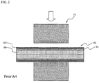
Meanwhile, the pouch-shaped secondary battery is manufactured as follows. First, as shown in FIGS. 1 to 3, an electrode assembly 10 is placed in a pouch-shaped battery case 40, and then an outer edge sealed portion 60 of an electrode assembly receiving part 90 of the battery case 40 is pressed by a high-temperature sealing tool 70 such that inner sealant layers 66, which have a low melting point, are welded and bonded to each other. Subsequently, as shown in FIG. 4, an outer end 68 of the outer edge sealed portion 60 is cut by a cutter as indicated by reference numeral 80.
This manufacturing method provides the pouch-shaped secondary battery 100 with high sealing strength and excellent sealing efficiency. However, the sealing tool 70 has a flat sealing surface with the result that some of the welded inner sealant layers 66 are discharged to the opposite ends of the inner sealant layers 66 during pressing of the outer edge sealed portion 60.
As a result, as shown in FIGS. 4 and 5, the inner sealant layers 66 are discharged to the electrode assembly 10 to form a bead 67. The bead 67 may contact the electrode assembly 10 in the battery case, damaging the electrode assembly 10 or causing a defect of the electrode assembly 10 and thus lowering durability of the battery.
That is, the inner sealant layers 66 discharged in the direction opposite to the electrode assembly 10 are removed through the outer end film cutting process. However, the inner sealant layers 66 discharged to the electrode assembly 10 cannot be cut with the result that the inner sealant layers 66 may cause the secondary battery to be defective.
Therefore, there is a high necessity for a technology that is capable of fundamentally solving the above problem.
DISCLOSURE Technical Problem
Therefore, the present invention has been made to solve the above problem and other technical problems that have yet to be resolved.
Specifically, it is an object of the present invention to provide a secondary battery configured to have a structure in which a protuberance is formed at an outer edge sealed portion of an electrode assembly receiving part of a battery case such that the protuberance protrudes upward and downward from the sealed portion, and the protuberance extends along the outer edge of the electrode assembly receiving part continuously in a curved line or in a straight line in a state in which the protuberance is adjacent to the electrode assembly receiving part, thereby preventing contact between a part of the sealed portion and an electrode assembly and thus preventing damage to or a defect of the electrode assembly.
Technical Solution
In accordance with one aspect of the present invention, the above and other objects can be accomplished by the provision of a plate-shaped secondary battery configured to have a structure in which an electrode assembly of a cathode/separator/anode structure is mounted in a battery case in a sealed state by thermal welding, wherein a protuberance is formed at an outer edge sealed portion of an electrode assembly receiving part of the battery case such that the protuberance protrudes upward and downward from the sealed portion, and the protuberance extends along the outer edge of the electrode assembly receiving part continuously in a curved line or in a straight line in a state in which the protuberance is adjacent to the electrode assembly receiving part.
That is, the secondary battery according to the present invention is configured such that the protuberance formed at the outer edge sealed portion of the electrode assembly receiving part of the battery case extends along the outer edge of the electrode assembly receiving part continuously in a curved line or in a straight line in a state in which the protuberance is adjacent to the electrode assembly receiving part. Consequently, it is possible for the protuberance to prevent molten material from flowing to the electrode assembly during thermal welding, thereby preventing contact between a part of the sealed portion and the electrode assembly and thus preventing damage to or a defect of the electrode assembly.
In a preferred example, the protuberance may be formed in noncontact with the electrode assembly receiving part.
The protuberance may be formed throughout the entirety of the outer edge sealed portion of the electrode assembly receiving part continuously in a curved line or in a straight line. Even in a case in which the protuberance is formed at one side of the outer edge sealed portion of the electrode assembly receiving part, however, it is possible to prevent the molten material from contacting the electrode assembly by adjusting the amount of the molten material and the distance between the protuberance and the molten material. In this case, productivity is improved and manufacturing costs are reduced as compared with a case in which the protuberance is formed throughout the entirety of the outer edge sealed portion of the electrode assembly receiving part.
For example, in a case in which the electrode assembly is formed in a quadrangular shape, the protuberance may be formed at only one of the four sides of the outer edge sealed portion of the electrode assembly receiving part.
Specifically, a quadrangular secondary battery having four sides according to an embodiment of the present invention may be manufactured as follows. First, an electrode assembly is placed in an electrode assembly receiving part of a battery case, the battery case is disposed on the electrode assembly to cover the electrode assembly, and three sides of the battery case are sealed. At this time, the three sides of the battery case may be sealed such that protuberances are not formed at the three sides of the battery case.
After the three sides of the battery case are sealed, an electrolyte is injected into the battery case through the other side, which is not sealed, of the battery case. At this time, the unsealed side of the battery case has a margin equivalent to 0.5 to 1 times the size of the electrode assembly. During sealing, therefore, the other side of the battery case is sealed at a position spaced apart from the electrode assembly receiving part by a predetermined distance, and then the battery is charged once.
Subsequently, the margin of the battery case is cut to discharge gas from the battery case, the other side of the battery case is sealed at a position adjacent to the electrode assembly receiving part, and the other side of the battery case is cut into the final size. After the battery case is filled with the electrolyte, it is necessary to prevent a casting propylene (cPP) molten material from coming into contact with the electrode assembly. To this end, the other side of the battery case may be sealed in a state in which a protuberance is formed at the other side of the battery case. In this case, the protuberance may be formed only at the other side of the battery case.
That is, the protuberance may be formed only in the degassing and resealing process. Alternatively, protuberances may be formed at three sides of the battery case. As a result, the protuberances may be formed at one or more sides of the battery case.
The protuberance may have a width equivalent to 30% or less that of the sealed portion. Also, the protuberance may have a height equivalent to 105% to 300% that of the sealed portion. Preferably, the width of the protuberance may be 5 to 25% that of the sealed portion, and the height of the protuberance may be 150% to 250% that of the sealed portion.
If the width of the protuberance is too much less than that of the sealed portion or the height of the protuberance is too much less than that of the sealed portion, it is not possible for the protuberance to sufficiently block the molten material flowing to the electrode assembly during thermal welding of the sealed portion. On the other hand, if the width of the protuberance is too much greater than that of the sealed portion or the height of the protuberance is too much greater than that of the sealed portion, the sealed area of the sealed portion is reduced during thermal welding of the sealed portion with the result that sealing force of the sealed portion is lowered.
In a concrete example, the protuberance may have a height of 1 mm or less and a width of 0.5 to 2 mm.
Preferably, the protuberance is formed at the outer edge sealed portion of the electrode assembly receiving part such that the protuberance is adjacent to the electrode assembly receiving part.
It is an ultimate object of the present invention to control the flow of surplus molten material, thereby blocking the molten material flowing to the electrode assembly. That is, the surplus molten material is accommodated in the protuberance formed along the outer edge of the electrode assembly receiving part continuously in a curved line or in a straight line during thermal welding such that the molten material cannot contact the electrode assembly.
For example, the middle of the protuberance may be spaced apart from the electrode assembly receiving part by a distance equivalent to 40% or less the width of the sealed portion.
Specifically, in a case in which the protuberance is formed such that the middle of the protuberance is spaced apart from the electrode assembly receiving part by a distance equivalent to greater than 40% the width of the sealed portion, a relatively large amount of surplus molten material flows to the electrode assembly, which is not preferable. Furthermore, the width of the sealed portion is increased with the result that the total size of the battery is increased, which is also not preferable.
In another concrete example, the protuberance may be formed such that the middle of the protuberance is spaced apart from the electrode assembly receiving part by 3 mm or less. Preferably, the distance from the electrode assembly receiving part to the middle of the protuberance is less than 3 mm.
In a preferred example, the protuberance may be formed at the sealed portion when the sealed portion is thermally welded using a sealing tool to thermally weld the sealed portion. The sealing tool may include an upper sealing tool to downwardly press the top of the sealed portion and a lower sealing tool to support the bottom of the sealed portion.
In the above, inwardly depressed grooves may be formed at the bottom of the upper sealing tool and the top of the lower sealing tool corresponding to the protuberance.
During thermal welding of the sealed portion in which the upper sealing tool downwardly presses the top of the sealed portion while the bottom of the sealed portion is supported by the lower sealing tool, therefore, some of the sealed portion is moved into the inwardly depressed grooves formed at the bottom of the upper sealing tool and the top of the lower sealing tool. Consequently, the protuberance is easily formed.
Each of the grooves may be formed in the shape of at least one selected from a group consisting of a quadrangle, a semicircle, a triangle, and a trapezoid. Preferably, each of the grooves is formed in a quadrangular shape.
Meanwhile, an end of the sealed portion may be cut after the protuberance is formed at the sealed portion using the sealing tool. Consequently, a bead formed at the outer end of the sealed portion during thermal welding of the sealed portion may be easily cut and removed.
The battery case is preferably applied to a secondary battery including an electrode assembly mounted in a pouch-shaped battery case formed of a laminate sheet, specifically an aluminum laminate sheet, including a resin layer and a metal layer.
The laminate sheet may include an outer coating layer formed of polymer film, a barrier layer formed of metal foil, and an inner sealant layer formed of a polyolefin-based material. It is required for the outer coating layer to exhibit excellent resistance to an external environment, and therefore, it is necessary for the outer coating layer to exhibit predetermined tensile strength and weather resistance. In this regard, oriented nylon film or polyethylene terephthalate (PET) are preferably used as the polymer resin for the outer coating layer. The barrier layer may be formed of, preferably, aluminum to prevent the introduction or leakage of foreign matter, such as gas or moisture, and increase the strength of the battery case. The inner sealant layer may be made of, preferably, a polyolefin-based material exhibiting a high thermal welding property (a thermal adhesion property), a low hygroscopic property to restrain the leakage of an electrolyte and to block moisture, and a property of not being expanded or corroded by the electrolyte, more preferably cast polypropylene (cPP).
Consequently, the inner sealant layer, which has a low melting point, of the laminate sheet is captured during thermal welding of the sealed portion, whereby the protuberance is easily formed.
Also, the protuberance may be spaced apart from the electrode assembly receiving part. This is because the protuberance formed at a position spaced apart from the electrode assembly receiving part has higher adhesive strength than the protuberance formed at a position contacting the electrode assembly receiving part.
According to circumstances, each of the grooves may have a space of a size greater than that of the protuberance formed at the outer edge sealed portion such that the protuberance cannot be damaged, and the protuberance may be formed at a position adjacent to the electrode assembly receiving part of the battery case while the protuberance does not contact the electrode assembly receiving part of the battery case. In this case, it is possible to effectively accommodate the inner sealant layer in the grooves, which is preferable.
The structure of the electrode assembly is not particularly restricted so long as the electrode assembly is configured to have a structure including a cathode, an anode, and a separator disposed between the cathode and the anode. Based on the shape thereof, the electrode assembly may be formed in a polygonal shape, a circular shape, or an oval shape. Based on the structure thereof, the electrode assembly may be configured to have a stacked type structure, a folded type structure, or a stacked/folded type structure.
The outer edge sealed portion of the battery case of the secondary battery including the stacked type electrode assembly may have a protuberance continuously formed at one or more sides thereof corresponding to the electrode assembly in a curved line or in a straight line.
Also, the outer edge sealed portion of the electrode assembly receiving part of the secondary battery including the folded type or stacked/folded type electrode assembly may have a protuberance continuously formed at some or the entirety of the outer edge thereof corresponding to the electrode assembly in a curved line or in a straight line.
The details of the stacked/folded type electrode assembly are disclosed in Korean Patent Application Publication No. 2001-0082058, No. 2001-0082059, and No. 2001-0082060, which have been filed in the name of the applicant of the present patent application. The disclosures of the above-mentioned patent publications are hereby incorporated by reference as if fully set forth therein.
The secondary battery according to the present invention may be a lithium secondary battery. In particular, the secondary battery according to the present invention is preferably applied to a so-called a lithium ion polymer battery having an electrode assembly impregnated with a lithium-containing electrolyte in the form of a gel.
In accordance with another aspect of the present invention, there is provided a middle or large-sized battery module including the secondary battery as a unit cell.
The secondary battery according to the present invention is preferably used in a high-power, large-capacity battery requiring a long lifespan and excellent durability or a middle or large-sized battery module including a plurality of such batteries as unit cells. The middle or large-sized battery module may be used as a power source for, for example, electric vehicles, hybrid electric vehicles, plug-in hybrid electric vehicles, electric motorcycles, and electric bicycles.
The structure of the middle or large-sized battery module and a method of manufacturing the same are well known in the art to which the present invention pertains, and therefore, a detailed description thereof will be omitted.
DESCRIPTION OF DRAWINGS
The above and other objects, features and other advantages of the present invention will be more clearly understood from the following detailed description taken in conjunction with the accompanying drawings, in which:
FIG. 1 is a front see-through view showing a general structure of a conventional pouch-shaped secondary battery;
FIGS. 2 to 4 are typical views sequentially showing processes of thermally welding a sealed portion provided at the outer edge of a battery case to manufacture the pouch-shaped secondary battery of FIG. 1;
FIG. 5 is a sectional view taken along line A-A′ of FIG. 1 typically showing the secondary battery manufactured through the thermal welding process of FIG. 4;
FIG. 6 is a front see-through view showing a secondary battery according to an embodiment of the present invention;
FIG. 7 is a typical view showing a thermal welding process according to an embodiment of the present invention;
FIG. 8 is a sectional view taken along line B-B′ of FIG. 6 typically showing the secondary battery manufactured through the thermal welding process of FIG. 7;
FIG. 9 is an enlarged typical view showing a region C of FIG. 8; and
FIG. 10 is a series of vertical sectional views typically showing structures of upper sealing tools used in experiments according to the present invention.
BEST MODE
Now, preferred embodiments of the present invention will be described in detail with reference to the accompanying drawings. It should be noted, however, that the scope of the present invention is not limited by the illustrated embodiments.
FIG. 6 is a front see-through view showing a secondary battery according to an embodiment of the present invention.
Referring to FIG. 6, a secondary battery 100 a is configured to have a structure in which an electrode assembly 10 of a cathode/separator/anode structure is mounted in a battery case 40 a in a sealed state by thermal welding.
Also, an outer edge sealed portion 60 a of an electrode assembly receiving part 90 of the battery case 40 a is provided with a protuberance 92 protruding upward and downward from the sealed portion 60 a. The protuberance 92 extends linearly along a portion of the outer edge of the electrode assembly receiving part 90 in a state in which the protuberance 92 is adjacent to the electrode assembly receiving part 90.
Specifically, the secondary battery 100 a includes an electrode assembly 10, a battery case 40 a in which the electrode assembly 10 is mounted, and two electrode leads 20 and 22 electrically connected to electrode tabs 30 and 32 of the electrode assembly 10, respectively.
The two electrode leads 20 and 22 are electrically connected to the electrode tabs 30 and 32 extending from corresponding electrode plates of the electrode assembly 10, respectively, for example, by welding. The electrode leads 20 and 22 are partially exposed from the battery case 40 a. To upper and lower surfaces of the electrode leads 20 and 22 are partially attached insulative films 50 and 52 to improve sealability between the battery case 40 a and the electrode leads 20 and 22 and, at the same time, to secure electrical insulation between the battery case 40 a and the electrode leads 20 and 22, respectively. In this embodiment, the two electrode leads 20 and 22, i.e. a cathode and an anode, are opposite to each other. Alternatively, the two electrode leads 20 and 22 may be disposed side by side in the same direction.
The battery case 40 a is formed of an aluminum laminate sheet. The electrode assembly receiving part 90 to receive the electrode assembly 10 is formed at the battery case 40 a. At the outer edge sealed portion 60 a of the electrode assembly receiving part 90, an upper battery case and a lower battery case are coupled to each other by thermal welding. As a result, the battery case 40 a is formed generally in a pouch shape.
FIG. 7 is a typical view showing a thermal welding process according to an embodiment of the present invention, and FIG. 8 is a sectional view taken along line B-B′ of FIG. 6 typically showing the secondary battery manufactured through the thermal welding process of FIG. 7.
Referring to these drawings together with FIG. 6, the protuberance 92 is formed at the sealed portion 60 a when the sealed portion 60 a is thermally welded using a sealing tool 70 a to thermally weld the sealed portion 60 a.
The sealing tool 70 a includes an upper sealing tool 72 a to downwardly press the top of the sealed portion 60 a and a lower sealing tool 74 a to support the bottom of the sealed portion 60 a. Inwardly depressed grooves 722 a and 742 a are respectively formed at the bottom of the upper sealing tool 72 a and the top of the lower sealing tool 74 a corresponding to the protuberance 92.
Each of the grooves 772 a and 742 a is formed in a rectangular shape in vertical section. The protuberance 92 is formed in a semicircular shape in a state in which the protuberance 92 protrudes upward and downward from the sealed portion 60 a by the grooves 772 a and 742 a of the upper sealing tool 72 a and the lower sealing tool 74 a.
Subsequently, an outer end of the sealed portion 60 a is cut, thereby completing the secondary battery 100 a of FIG. 8.
The battery case 40 a is formed of an aluminum laminate sheet including a resin layer and a metal layer. The laminate sheet includes an outer coating layer 62 formed of polymer film, a barrier layer 64 formed of metal foil, and an inner sealant layer 66 formed of a polyolefin-based material. During thermal welding of the sealed portion 60 a, the inner sealant layer 66, which has a low melting point, is captured in the grooves 772 a and 742 a of the upper sealing tool 72 a and the lower sealing tool 74 a, whereby the protuberance 92 is formed.
FIG. 9 is an enlarged typical view showing a region C of FIG. 8.
Referring to FIG. 9, a width w of the protuberance 92 is about 20% a width W of the sealed portion 60 a, and a height h of the protuberance 92 is about 120% a height H of the sealed portion 60 a. Also, a length d between the middle of the protuberance 92 and the electrode assembly receiving part is about 22% the width W of the sealed portion. The length d means the distance from the electrode assembly receiving part to the middle of the protuberance.
FIG. 10 is a series of vertical sectional views typically showing structures of sealing tools used in experiments according to the present invention.
Referring to FIG. 10 together with FIG. 9, structure 1 shows a sealing tool having no groove, and structure 2 to structure 5 show sealing tools having different lengths d (FIG. 9) between the middle of a groove (corresponding to the protuberance of the battery case) and one end (corresponding to the electrode assembly receiving part).
Although only upper sealing tools are shown in FIG. 10 for the sake of convenience, it should be understood that the sealing tools used in experiments according to the present invention further include lower sealing tools configured such that the upper sealing tools and the lower sealing tools are vertically symmetrical to each other.
Experiment results obtained by thermally welding outer edge sealed portions of electrode assembly receiving parts of battery cases using the sealing tools of FIG. 10 are revealed in Table 1 below.
Table 1 reveals reduction ratios of the amounts of inner sealant layers discharged into batteries when sealing tools (structure 2 to structure 5), each of which had a groove, were used to the amount of an inner sealant layer discharged into a battery when a sealing tool (structure 1) having no groove was used.
Experiments were carried out as follows. Outer edge sealed portions of electrode assembly receiving parts of battery cases, each of which included an outer coating layer (PET), a barrier layer (aluminum), and an inner sealant layer (PP), were thermally welded at a temperature of 170 to 200° C. for 1 second or less using sealing tools (NAK80). Also, a width e of each of the sealing tools was 10 mm, and a width of a groove of each of the sealing tools was 1.2 mm.
TABLE 1
Reduction ratio of amount
Sealing tool Distance between middle of inner sealant layer
structure of groove and one end discharged into battery
Structure
2 1.26 mm (d1) 68%
Structure
3 3 mm (d2) 56%
Structure
4 5 mm (d3) 40%
Structure
5 7 mm (d4) 23%
Generally, when the reduction ratio of the amount of the inner sealant layer is 50% or more, it is effective to prevent contact between the inner sealant layer and the electrode assembly.
As can be seen from Table 1 above, therefore, the reduction ratio of the amount of the inner sealant layer is 50% or more in structure 2 and structure 3 in which the length between the middle of the groove of the sealing tool and one end is 3 mm or less. Consequently, it is more effective to improve safety of the battery as compared with the reduction ratio of the amount of the inner sealant in structure 4 and structure 5 in which the length between the middle of the groove of the sealing tool and one end is more than 3 mm.
Although the preferred embodiments of the present invention have been disclosed for illustrative purposes, those skilled in the art will appreciate that various modifications, additions and substitutions are possible, without departing from the scope and spirit of the invention as disclosed in the accompanying claims.
[Industrial Applicability]
As is apparent from the above description, a secondary battery according to the present invention is configured such that a protuberance is formed at an outer edge sealed portion of an electrode assembly receiving part such that the protuberance protrudes upward and downward from the sealed portion, and the protuberance extends along the outer edge of the electrode assembly receiving part continuously in a curved line or in a straight line in a state in which the protuberance is adjacent to the electrode assembly receiving part. Consequently, it is possible to prevent contact between a part of the sealed portion and an electrode assembly, thereby preventing damage to or a defect of the electrode assembly.

Claims (19)

The invention claimed is:
1. A plate-shaped secondary battery configured to have a structure in which an electrode assembly of a cathode/separator/anode structure is mounted in a battery case in a sealed state by thermal welding, wherein a protuberance is formed at an outer edge sealed portion of an electrode assembly receiving part of the battery case such that the protuberance protrudes upward and downward from the sealed portion, and the protuberance extends along the outer edge of the electrode assembly receiving part continuously in a curved line or in a straight line in a state in which the protuberance is adjacent to the electrode assembly receiving part,
wherein the protuberance has a height equivalent to 105% to 300% that of the sealed portion,
wherein the protuberance has a width equivalent to 30% or less that of the sealed portion, and
wherein a middle of the protuberance is spaced apart from the electrode assembly receiving part by a distance equivalent to 40% or less a width of the sealed portion.
2. The secondary battery according to claim 1, wherein the protuberance is-apart from the electrode assembly receiving part.
3. The secondary battery according to claim 1, wherein the protuberance is formed at the sealed portion when the sealed portion is thermally welded using a sealing tool to thermally weld the sealed portion.
4. The secondary battery according to claim 3, wherein the sealing tool comprises an upper sealing tool to downwardly press a top of the sealed portion and a lower sealing tool to support a bottom of the sealed portion.
5. The secondary battery according to claim 4, wherein inwardly depressed grooves are formed at a bottom of the upper sealing tool and a top of the lower sealing tool corresponding to the protuberance, respectively.
6. The secondary battery according to claim 5, wherein each of the grooves is formed in the shape of at least one selected from a group consisting of a quadrangle, a semicircle, a triangle, and a trapezoid.
7. The secondary battery according to claim 3, wherein an end of the sealed portion is cut after the protuberance is formed at the sealed portion using the sealing tool.
8. The secondary battery according to claim 1, wherein the battery case is formed of a laminate sheet comprising a resin layer and a metal layer.
9. The secondary battery according to claim 8, wherein the laminate sheet is an aluminum laminate sheet.
10. The secondary battery according to claim 8, wherein the laminate sheet comprises an outer coating layer formed of polymer film, a barrier layer formed of metal foil, and an inner sealant layer formed of a polyolefin-based material.
11. The secondary battery according to claim 10, wherein the protuberance is formed by capturing the inner sealant layer.
12. The secondary battery according to claim 1, wherein the electrode assembly is formed in a polygonal shape.
13. The secondary battery according to claim 12, wherein the outer edge sealed portion of the electrode assembly receiving part has a protuberance continuously formed at one or more sides thereof corresponding to the electrode assembly in a curved line or in a straight line.
14. The secondary battery according to claim 13, wherein the electrode assembly is configured to have a stacked type structure.
15. The secondary battery according to claim 1, wherein the electrode assembly is formed in a circular or oval shape.
16. The secondary battery according to claim 15, wherein the outer edge sealed portion of the electrode assembly receiving part has a protuberance continuously formed at some or the entirety of the outer edge thereof corresponding to the electrode assembly in a curved line or in a straight line.
17. The secondary battery according to claim 16, wherein the electrode assembly is configured to have a folded type or stacked/folded type structure.
18. The secondary battery according to claim 1, wherein the battery is a lithium ion polymer battery.
19. A battery module comprising a secondary battery according to claim 1 as a unit cell.
US13/819,344 2010-08-30 2011-08-11 Secondary battery of novel structure Active US9005805B2 (en)

Applications Claiming Priority (3)

Application Number Priority Date Filing Date Title
KR20100083796 2010-08-30
KR10-2010-0083796 2010-08-30
PCT/KR2011/005896 WO2012030080A2 (en) 2010-08-30 2011-08-11 Rechargeable battery having a novel structure

Related Parent Applications (1)

Application Number Title Priority Date Filing Date
PCT/KR2011/005896 A-371-Of-International WO2012030080A2 (en) 2010-08-30 2011-08-11 Rechargeable battery having a novel structure

Related Child Applications (1)

Application Number Title Priority Date Filing Date
US14/018,911 Continuation US9385350B2 (en) 2010-08-30 2013-09-05 Secondary battery of novel structure

Publications (2)

Publication Number Publication Date
US20130189570A1 US20130189570A1 (en) 2013-07-25
US9005805B2 true US9005805B2 (en) 2015-04-14

Family

ID=45773343

Family Applications (2)

Application Number Title Priority Date Filing Date
US13/819,344 Active US9005805B2 (en) 2010-08-30 2011-08-11 Secondary battery of novel structure
US14/018,911 Active 2032-03-17 US9385350B2 (en) 2010-08-30 2013-09-05 Secondary battery of novel structure

Family Applications After (1)

Application Number Title Priority Date Filing Date
US14/018,911 Active 2032-03-17 US9385350B2 (en) 2010-08-30 2013-09-05 Secondary battery of novel structure

Country Status (3)

Country Link
US (2) US9005805B2 (en)
KR (1) KR101269935B1 (en)
WO (1) WO2012030080A2 (en)

Families Citing this family (12)

* Cited by examiner, † Cited by third party
Publication number Priority date Publication date Assignee Title
KR101483239B1 (en) 2012-08-30 2015-01-16 주식회사 엘지화학 Packaging for a cable-type secondary battery and cable-type secondary battery including the same
EP2899771B1 (en) * 2012-12-24 2017-08-16 LG Chem, Ltd. Pouch-type secondary battery having sealing margin for improved durability
KR101763980B1 (en) * 2013-08-30 2017-08-01 주식회사 엘지화학 Sealiing tool of pouch type secondary battery
KR20170026230A (en) * 2015-08-27 2017-03-08 주식회사 엘지화학 apparatus for sealing secondary battery
KR101940150B1 (en) * 2015-12-11 2019-01-18 주식회사 엘지화학 Sealing apparatus for secondary battery
WO2017158986A1 (en) * 2016-03-15 2017-09-21 Necエナジーデバイス株式会社 Battery cell
JP7225760B2 (en) * 2018-12-17 2023-02-21 大日本印刷株式会社 Electric storage device manufacturing method and electric storage device quality control method
KR20200137419A (en) * 2019-05-30 2020-12-09 에스케이이노베이션 주식회사 Pouch-type secondary battery and battery module having thereof
CN113728495B (en) * 2020-03-19 2023-07-04 宁德新能源科技有限公司 Packaging structure of battery cell
KR20220140866A (en) * 2020-03-24 2022-10-18 동관 파워앰프 테크놀로지 리미티드 Electrochemical and electronic devices
CN111668508B (en) * 2020-06-16 2021-08-06 氢源科技(赣州)有限公司 Flow channel structure of bipolar plate of hydrogen fuel cell
KR20220161969A (en) * 2021-05-31 2022-12-07 현대자동차주식회사 Pouch type lithium secondary battery sealer, sealing method and pouch type lithium secondary battery manufactured by the same

Citations (8)

* Cited by examiner, † Cited by third party
Publication number Priority date Publication date Assignee Title
US5948562A (en) 1997-11-03 1999-09-07 Motorola, Inc. Energy storage device
US6877216B2 (en) 2000-01-26 2005-04-12 Dai Nippon Printing Co., Ltd. Heat-sealing machine, heat-sealing method, embossing method, work pressing machine and workpiece
JP2006093120A (en) 2004-09-22 2006-04-06 Samsung Sdi Co Ltd Secondary battery pouch and pouch-type secondary battery, and pouch-forming sealing device
US7041380B2 (en) 2001-06-20 2006-05-09 Dai Nippon Printing Co., Ltd. Packaging material for battery
US20060194103A1 (en) 2003-08-08 2006-08-31 Makihiro Otohata Film-Covered Battery And Fabrication Method
KR100763931B1 (en) 2006-06-27 2007-10-05 (주)비피에스 Method of making battery using as case with shrinkage tube
US20080070100A1 (en) 2006-09-18 2008-03-20 Lg Twin Towers 20 Pouch-shaped secondary battery with improved safety
KR20100126226A (en) 2009-05-21 2010-12-01 주식회사 엘지화학 Pouch type secondary battery characterized by water-resistance

Family Cites Families (1)

* Cited by examiner, † Cited by third party
Publication number Priority date Publication date Assignee Title
JP2004047185A (en) * 2002-07-09 2004-02-12 Nissan Motor Co Ltd Sealing structure of battery, and mounting board of this battery

Patent Citations (10)

* Cited by examiner, † Cited by third party
Publication number Priority date Publication date Assignee Title
US5948562A (en) 1997-11-03 1999-09-07 Motorola, Inc. Energy storage device
US6877216B2 (en) 2000-01-26 2005-04-12 Dai Nippon Printing Co., Ltd. Heat-sealing machine, heat-sealing method, embossing method, work pressing machine and workpiece
US7041380B2 (en) 2001-06-20 2006-05-09 Dai Nippon Printing Co., Ltd. Packaging material for battery
US20060194103A1 (en) 2003-08-08 2006-08-31 Makihiro Otohata Film-Covered Battery And Fabrication Method
JP2006093120A (en) 2004-09-22 2006-04-06 Samsung Sdi Co Ltd Secondary battery pouch and pouch-type secondary battery, and pouch-forming sealing device
US20060093905A1 (en) * 2004-09-22 2006-05-04 Joong Heon Kim Pouch for secondary battery, secondary battery using the same, and apparatus for sealing pouch cases of secondary battery
KR100763931B1 (en) 2006-06-27 2007-10-05 (주)비피에스 Method of making battery using as case with shrinkage tube
US20080070100A1 (en) 2006-09-18 2008-03-20 Lg Twin Towers 20 Pouch-shaped secondary battery with improved safety
KR100913836B1 (en) 2006-09-18 2009-08-26 주식회사 엘지화학 Pouch-typed Secondary Battery with Improved Safety
KR20100126226A (en) 2009-05-21 2010-12-01 주식회사 엘지화학 Pouch type secondary battery characterized by water-resistance

Non-Patent Citations (1)

* Cited by examiner, † Cited by third party
Title
International Search Report issued in PCT/KR2011/005896, mailed on Mar. 9, 2012.

Also Published As

Publication number Publication date
US9385350B2 (en) 2016-07-05
KR101269935B1 (en) 2013-05-31
WO2012030080A3 (en) 2012-05-03
US20140004410A1 (en) 2014-01-02
US20130189570A1 (en) 2013-07-25
WO2012030080A2 (en) 2012-03-08
KR20120021194A (en) 2012-03-08

Similar Documents

Publication Publication Date Title
US9005805B2 (en) Secondary battery of novel structure
US8012617B2 (en) Secondary battery having sealing portion of novel structure
US8043743B2 (en) Pouch type secondary battery with improved safety
EP3151307B1 (en) Battery module and battery pack comprising same
EP2602840B1 (en) Secondary battery pouch having improved stability, pouch-type secondary battery using same, and medium- or large-sized battery pack
KR101216422B1 (en) Secondary Battery Having Sealing Portion of Improved Insulating Property
KR101472167B1 (en) Pouch of improved safety for secondary battery and secondary battery, battery pack using the same
KR101472168B1 (en) Secondary battery having improved safety, and battery pack using the same
KR101428458B1 (en) Secondary Battery of Structure Having Raised Portion at Sealing Part and Manufacturing Method thereof
KR101306187B1 (en) Device for Eliminating Gas from Battery Cell and Method for Manufacturing Battery Cell
US10003049B2 (en) Secondary battery of improved safety
KR101499471B1 (en) Method for Manufacturing a secondary Battery and the secondary Battery Manufactured Thereby
KR20200108719A (en) Secondary Battery
US8673476B2 (en) Electrode assembly having stable lead-tap joint and electrochemical cell containing them
KR20160080559A (en) A pouch type secondary battery with an enhanced sealing part and a method for manufacturing the secondary battery
KR20140067246A (en) Battery cell having nozzle member
KR20130035754A (en) Second battery with porous structures and battery module using the same
KR101292284B1 (en) Secondary Battery Having Sealing Portion of Novel Structure
KR102169373B1 (en) Battery Case Comprising Clad-typed Metal Layer and Battery Cell Comprising the Same
KR20190109146A (en) The Apparatus For Taping The Secondary Battery
KR20140052917A (en) Elctrochemical cell and method for producing same
KR20090076278A (en) Secondary battery with excellent sealability
KR102082655B1 (en) Method Preparing Electrode Assembly Having Corner Cutting Structure and Electrode Assembly Prepared Using the Same
KR101444507B1 (en) Battery Pouch having enhanced electrical insulation
US20230373138A1 (en) Apparatus and Method for Molding Battery Case, and Battery Case

Legal Events

Date Code Title Description
AS Assignment

Owner name: LG CHEM, LTD., KOREA, REPUBLIC OF

Free format text: ASSIGNMENT OF ASSIGNORS INTEREST;ASSIGNORS:PARK, WONCHAN;KIM, MIN SU;IM, YE HOON;AND OTHERS;SIGNING DATES FROM 20130228 TO 20130325;REEL/FRAME:030181/0230

FEPP Fee payment procedure

Free format text: PAYOR NUMBER ASSIGNED (ORIGINAL EVENT CODE: ASPN); ENTITY STATUS OF PATENT OWNER: LARGE ENTITY

STCF Information on status: patent grant

Free format text: PATENTED CASE

MAFP Maintenance fee payment

Free format text: PAYMENT OF MAINTENANCE FEE, 4TH YEAR, LARGE ENTITY (ORIGINAL EVENT CODE: M1551); ENTITY STATUS OF PATENT OWNER: LARGE ENTITY

Year of fee payment: 4

AS Assignment

Owner name: LG ENERGY SOLUTION, LTD., KOREA, REPUBLIC OF

Free format text: ASSIGNMENT OF ASSIGNORS INTEREST;ASSIGNOR:LG CHEM, LTD.;REEL/FRAME:058295/0068

Effective date: 20211027

MAFP Maintenance fee payment

Free format text: PAYMENT OF MAINTENANCE FEE, 8TH YEAR, LARGE ENTITY (ORIGINAL EVENT CODE: M1552); ENTITY STATUS OF PATENT OWNER: LARGE ENTITY

Year of fee payment: 8