US9008239B2 - Collision detection using a multiple symbol noncoherent soft output detector - Google Patents
Collision detection using a multiple symbol noncoherent soft output detector Download PDFInfo
- Publication number
- US9008239B2 US9008239B2 US13/831,825 US201313831825A US9008239B2 US 9008239 B2 US9008239 B2 US 9008239B2 US 201313831825 A US201313831825 A US 201313831825A US 9008239 B2 US9008239 B2 US 9008239B2
- Authority
- US
- United States
- Prior art keywords
- symbol
- collision
- soft
- observations
- input signal
- Prior art date
- Legal status (The legal status is an assumption and is not a legal conclusion. Google has not performed a legal analysis and makes no representation as to the accuracy of the status listed.)
- Expired - Fee Related
Links
Images


Classifications
-
- H—ELECTRICITY
- H04—ELECTRIC COMMUNICATION TECHNIQUE
- H04L—TRANSMISSION OF DIGITAL INFORMATION, e.g. TELEGRAPHIC COMMUNICATION
- H04L1/00—Arrangements for detecting or preventing errors in the information received
- H04L1/004—Arrangements for detecting or preventing errors in the information received by using forward error control
- H04L1/0045—Arrangements at the receiver end
- H04L1/0054—Maximum-likelihood or sequential decoding, e.g. Viterbi, Fano, ZJ algorithms
-
- H—ELECTRICITY
- H04—ELECTRIC COMMUNICATION TECHNIQUE
- H04L—TRANSMISSION OF DIGITAL INFORMATION, e.g. TELEGRAPHIC COMMUNICATION
- H04L25/00—Baseband systems
- H04L25/02—Details ; arrangements for supplying electrical power along data transmission lines
- H04L25/03—Shaping networks in transmitter or receiver, e.g. adaptive shaping networks
- H04L25/03006—Arrangements for removing intersymbol interference
- H04L25/03171—Arrangements involving maximum a posteriori probability [MAP] detection
-
- H—ELECTRICITY
- H04—ELECTRIC COMMUNICATION TECHNIQUE
- H04L—TRANSMISSION OF DIGITAL INFORMATION, e.g. TELEGRAPHIC COMMUNICATION
- H04L25/00—Baseband systems
- H04L25/02—Details ; arrangements for supplying electrical power along data transmission lines
- H04L25/06—Dc level restoring means; Bias distortion correction ; Decision circuits providing symbol by symbol detection
- H04L25/067—Dc level restoring means; Bias distortion correction ; Decision circuits providing symbol by symbol detection providing soft decisions, i.e. decisions together with an estimate of reliability
-
- H—ELECTRICITY
- H04—ELECTRIC COMMUNICATION TECHNIQUE
- H04L—TRANSMISSION OF DIGITAL INFORMATION, e.g. TELEGRAPHIC COMMUNICATION
- H04L27/00—Modulated-carrier systems
- H04L27/0012—Modulated-carrier systems arrangements for identifying the type of modulation
-
- H—ELECTRICITY
- H04—ELECTRIC COMMUNICATION TECHNIQUE
- H04L—TRANSMISSION OF DIGITAL INFORMATION, e.g. TELEGRAPHIC COMMUNICATION
- H04L27/00—Modulated-carrier systems
- H04L27/18—Phase-modulated carrier systems, i.e. using phase-shift keying
- H04L27/22—Demodulator circuits; Receiver circuits
- H04L27/233—Demodulator circuits; Receiver circuits using non-coherent demodulation
Definitions
- the present invention relates to communication systems and more specifically to detection of tag collisions using a multiple symbol noncoherent soft output detector.
- noncoherent or differential detection is an attractive alternative to coherent detection due to the simplicity of implementation and/or where the transmission environment is sufficiently degraded, e.g., a multipath fading channel, that acquiring and tracking a coherent demodulation reference signal is difficult if not impossible.
- a noncoherent detector is a detector that does not directly estimate the phase of the received signal.
- the multiple symbol differential detection technique is a form of maximum-likelihood sequence estimation and assumes that carrier phase is constant during the extended observation interval, which is typically a reasonable assumption for observations of the order of three or four symbol observations.
- the multiple symbol differential detector described by Dr. Divsalar and Dr. Simon performs hard decisions.
- a hard decision is a decision between a fixed set of possible values (e.g. 0 or 1). In a soft output detector, each bit in the output also takes on a value indicating reliability.
- a receiver system includes a receiver configured to receive and sample a phase modulated input signal, and a multiple symbol noncoherent soft output detector configured to receive the sampled input signal and to generate a soft metric indicative of the reliability of a detected symbol based upon observations over multiple symbols, a collision detector configured to calculate a decision metric from a set of soft metrics generated by the multiple symbol noncoherent soft output detector and detect a collision when the decision metric satisfies a predetermined criterion.
- the soft metric is the Log Likelihood Ratio of the detected symbol based upon observations over multiple symbols.
- the observations include observations over a two symbol sequence.
- the observations include observations over a three symbol sequence.
- the set of soft metrics generated by the multiple symbol noncoherent soft output detector are generated based upon observations of a unique sequence of symbols identifying an RFID tag.
- the unique sequence of symbols identifying an RFID tag is an RN16 transmission.
- the decision metric is based upon a central moment of the distribution of the set of soft metrics generated by the multiple symbol noncoherent soft output detector.
- the decision metric is normalized over a power of the first moment of the distribution of the set of soft metrics generated by the multiple symbol noncoherent soft output detector.
- the predetermined criterion is the decision metric exceeding a threshold.
- the phase modulated input signal includes a preamble sequence and the threshold is based upon the preamble correlation normalized by the number of one half symbols used in the preamble.
- the decision metric is a count of the number of soft metrics in the set of soft metrics generated by the multiple symbol noncoherent soft output detector.
- the phase modulated input signal includes data that is phase modulated on a carrier and the multiple symbol differential detector assumes that carrier phase of the input signal is constant over the time duration of the observations.
- the phase modulated input signal is a binary phase modulated signal.
- phase modulated input signal is an FM0 modulated signal.
- the phase modulated input signal is a Multiple-Phase-Shift Keying modulated signal.
- the multiple symbol differential detector includes a plurality of matched filters having different numbers of samples configured to integrate the samples during each half-symbol period, and the multiple symbol differential detector is configured to use the outputs of each of the plurality of matched filters to determine the most likely symbol duration.
- Still another additional embodiment also includes an antenna configured to receive a phase modulated signal that includes symbols transmitted by an RFID tag.
- a yet further embodiment again includes receiving and sampling a phase modulated input signal to produce symbol samples, combining symbol samples to produce symbol observations, generating a soft metric indicative of the reliability of a detected symbol based upon symbol observations over multiple symbols, and calculating a decision metric from a set of generated soft metrics, and detecting a collision in received radio frequency transmissions when the calculated decision metric satisfies a predetermined criterion.
- the soft metric is the Log Likelihood Ratio of the detected symbol based upon observations over multiple symbols.
- the observations include observations over a two symbol sequence.
- the observations include observations over a three symbol sequence.
- the set of generated soft metrics were generated based upon observations of a unique sequence of symbols identifying an RFID tag.
- the unique sequence of symbols identifying an RFID tag is an RN16 transmission.
- the decision metric is based upon a central moment of the distribution of the set of generated soft metrics.
- the decision metric is normalized over a power of the first moment of the distribution of the set of generated soft metrics.
- the predetermined criterion is the decision metric exceeding a threshold.
- the phase modulated input signal includes a preamble sequence and the threshold is based upon the preamble correlation normalized by the number of one half symbols used in the preamble.
- the decision metric is a count of the number of soft metrics in the set of generated soft metrics that are below a second threshold.
- the phase modulated input signal includes data that is phase modulated on a carrier, and the multiple symbol differential detector assumes that carrier phase of the input signal is constant over the time duration of the observations.
- the phase modulated input signal is a binary phase modulated signal.
- the phase modulated input signal is an FM0 modulated signal.
- phase modulated input signal is a Multiple-Phase-Shift Keying modulated signal.
- combining symbol samples to produce symbol observations also includes using a plurality of matched filters having different numbers of samples to integrate the symbol samples during each half-symbol period and determining the most likely symbol duration using the integrated symbol samples.
- FIG. 1 conceptually illustrates a communication system in accordance with an embodiment of the invention.
- FIGS. 2A-2E illustrate the characteristics of FM0 modulated signals transmitted in accordance with the EPC Class 1 Generation 2 UHF Air Interface Protocol Standard.
- FIG. 3 illustrates the manner in which a hard decision FM0 3-bit multiple symbol noncoherent soft output detector can be modified to generate soft metrics.
- FIGS. 4A and 4B illustrate sample functions of LLRs over a sequence of 16 symbols for the cases of no collision and a two tag collision.
- FIG. 5 conceptually illustrates an RFID receiver system that that can perform collision detection in accordance with embodiments of the invention.
- FIGS. 6A and 6B are histograms illustrating LLR simulations for the cases of no collision and a two tag collision using LLRs over three symbol sequences.
- FIGS. 7A and 7B are histograms illustrating simulations of the variance Var for the cases of no collision and two tag collision using LLRs over three symbol sequences.
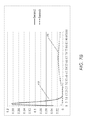
- FIGS. 8A and 8B are charts illustrating the simulated probability of false detection and the probability of miss detection for the cases of no collision and a two tag collision using LLR over three symbol sequences and the variance of LLR as a decision metric for the cases.
- FIGS. 9A-9D are normalized histograms illustrating simulations using the DM2 metric for two cases of no collision and two tag collision with various SNR.
- FIGS. 10A-10E are normalized histograms of illustrating simulations using the DM8 metric for two cases of no collision and two tag collision with various SNR.
- FIGS. 11A-11C are histograms illustrating LLR simulations for the cases of no collision and two tag collision using LLRs over two symbol sequences.
- FIGS. 12A-12D are histograms illustrating simulations of the variance Var for the cases of no collision and two tag collision using LLRs over two symbol sequences.
- FIGS. 13A and 13B are charts illustrating the simulated probability of false detection and the probability of miss detection for the cases of no collision and a two tag collision using LLR over two symbol sequences and the variance of LLR as a decision metric.
- the multiple symbol noncoherent soft output detector determines soft metrics based on the log likelihood ratio (LLR) for each detected symbol using observations with respect to multiple symbols.
- LLR log likelihood ratio
- the observations utilized to determine the soft metrics for each symbol can include observations of some or all of the symbols in the pilot and/or preamble and a short sequence of multiple data symbols.
- a short sequence of two or three unknown data symbols is utilized when generating the soft metric for an unknown data symbol.
- a sequence of any number of symbols can be utilized to determine the soft metrics.
- multiple symbol noncoherent soft output detectors in accordance with embodiments of the invention to produce soft metrics enables the output of more than one receiver to be utilized in the detection of a transmitted data sequence.
- soft metrics generated by a set of multiple symbol noncoherent soft output detectors can be combined to improve the reliability of the detected data sequence.
- the soft metrics can be used to discard the output of one or more multiple symbol noncoherent soft output detectors in a set of multiple symbol noncoherent soft output detectors when detecting data.
- the soft metrics can be utilized to select the most reliable output as the detected data sequence.
- multiple symbol noncoherent soft output detectors and the use of LLRs when performing multiple symbol noncoherent detection in accordance with embodiments of the invention are discussed further below.
- examples are provided with respect to the FM0 modulation technique used in common Radio Frequency Identification (RFID) applications.
- RFID Radio Frequency Identification
- multiple symbol noncoherent soft output detectors in accordance with embodiments of the invention can be utilized in any of a variety of applications including applications involving Multiple Phase Shift Keying, and/or wireless, wired, optical communication channels and systems with channel coding.
- One or more multiple symbol noncoherent soft output detectors in accordance with embodiments of the invention can be utilized to detect data in almost any communication system that modulates the phase of the transmitted signal to communicate information and where the phase of the carrier signal on which the data is modulated remains relatively constant during the transmission of the data sequence.
- a communication system including a set of multiple symbol noncoherent soft output detectors in accordance with embodiments of the invention is illustrated in FIG. 1 .
- the communication system 10 includes a transmitter 12 that modulates data symbols onto a carrier for transmission via a communication channel to one or more receiver systems 14 .
- a set of receiver systems 14 is provided and each receiver system includes a receiver 16 and a multiple symbol noncoherent soft output detector 18 .
- the receivers 16 demodulate and sample the received signal. The samples are provided to the corresponding multiple symbol noncoherent soft output detector 18 , which outputs soft metrics based upon the observations (i.e. the samples).
- the soft metrics based on the LLR are in fact the LLR of each symbol. In a number of embodiments, the soft metrics based on the LLR are approximations of the magnitude or square of the magnitude of the LLR. In other embodiments, any soft metric that provides information concerning the reliability of the detected symbol can be utilized.
- the soft metrics can be utilized to detect a received data sequence. In combined receiver systems where only one receiver system is present, the soft metrics output by the multiple symbol noncoherent soft output detector can be utilized to generate the received data sequence. In the illustrated embodiment, the soft metrics output by the multiple symbol noncoherent soft output detectors 18 are provided to a combiner 20 .
- the combiner 20 selects as the detected output a symbol or sequence of symbols based upon the output of the multiple symbol noncoherent soft output detector 18 that detects the symbol or sequence of symbols with the highest reliability. In several embodiments, combiner 20 combines the soft metrics from two or more of the multiple symbol noncoherent soft output detectors to generate the detected data sequence. The soft metrics utilized to generate the detected data sequence can be selected based upon reliability. Alternatively, the combiner 20 can simply combine the soft metrics of all of the multiple symbol noncoherent soft output detectors without regard to the reliability of any specific output.
- multiple symbol noncoherent soft output detectors in accordance with embodiments of the invention can be utilized in a variety of communication system including (but not limited to) wireless, wired, optical communication systems and systems with channel coding.
- An application of particular interest for multiple symbol noncoherent soft output detectors in accordance with embodiments of the invention is the detection of FM0 modulated data transmitted by Radio Frequency Identification (RFID) tags such as (but not limited to) Ultra High Frequency RFID tags that conform with the EPC Class 1 Generation 2 UHF Air Interface Protocol (EPC Gen 2) Standard specified by GS1 AISBL of Brussels, Belgium. Accordingly, much of the discussion that follows is in the context of detecting FM0 modulated signals.
- RFID Radio Frequency Identification
- multiple symbol noncoherent soft output detectors in accordance with embodiments of the invention can generate soft metrics with respect to symbols generated using a variety of phase modulation techniques including (but not limited to) Multiple-Phase-Shift Keying (MPSK).
- MPSK Multiple-Phase-Shift Keying
- the modulation scheme used to transmit the data should inherently include differential encoding or a differential encoder should be used.
- a modulation scheme that does not include differential encoding can be used.
- Multiple symbol noncoherent soft output detectors in accordance with embodiments of the invention detect received symbols by generating soft metrics using observations of multiple symbols.
- the multiple symbol noncoherent soft output detector generates soft metrics based on the LLR of each detected symbol.
- the following example is provided with respect to the detection of FM0 modulated symbols generated in accordance with the EPC Gen 2 standard.
- each data packet transmitted in accordance with the EPC Gen 2 standard includes a known pilot and preamble, which can be utilized by the receiver to improve the reliability of the detected data. Similar techniques can be utilized in communication systems that utilize other phase modulation techniques and/or for which the receiver system knows a portion of the transmitted sequence.
- the FM0 basis functions are illustrated in FIG. 2A .
- a state diagram illustrating the manner in which FM0 modulated symbols are generated is illustrated in FIG. 2B .
- each FM0 symbol that is transmitted depends on the previous symbol.
- FM0 symbols transmitted depending upon the value of the previous symbol are illustrated in FIG. 2C .
- Two bit (two symbol) FM0 sequences are illustrated in FIG. 2D .
- the EPC Gen 2 standard specifies that a RFID tag can transmit FM0 modulated data preceded by a preamble.
- the interrogator can also request that the RFID tag initiate the transmission with a pilot sequence of 12 leading FM0 zeros.
- the pilot and preamble sequence of a packet transmitted in accordance with the EPC Gen 2 Standard is illustrated in FIG. 2E .
- Both the pilot and preamble are known to the receiver system.
- the detection of FM0 modulated data utilizing observations of the pilot and preamble in the generation of soft metrics is discussed further below.
- Increasing the number of observations using the pilot and preamble typically improves the reliability of the detected data sequence.
- Use of observations of known symbols is not, however, necessary to detect data using a multiple symbol noncoherent soft output detector in accordance with embodiments of the invention.
- a number of matched filters having different numbers of samples can be utilized to integrate the samples during each half-symbol period to determine the most likely symbol duration.
- the integration typically commences halfway through the symbol interval.
- the carrier phase ⁇ (uniformly distributed between 0 and 2 ⁇ ) can be assumed to be almost constant over time duration of pilot, preamble, and data during reception of a packet.
- the conditional probability is
- the LLR then can be computed as
- P ⁇ ( x k - 1
- p , r ) ⁇ x : x k - 1 ⁇ P ⁇ ( x
- p , x ) ⁇ x : x k - 1 ⁇ P ⁇ ( r
- p , x ) max x : x k - 1 ⁇ P ⁇ ( r
- p , x ) ( 4 ) or ⁇ k ⁇ max x:x k +1 ln P ( r
- p,x ) ⁇ max x:x k ⁇ 1 ln P ( r
- a multiple symbol noncoherent soft output detector can be constructed in accordance with embodiments of the invention that generates a LLR with respect to each possible symbol in an M-ary PSK modulation scheme.
- the soft metric is determined relative to the likelihood of an arbitrarily selected reference symbol value.
- the detector of an RFID receiver such as the RFID Receiver described in U.S. Pat. No. 7,633,377 entitled “RFID Receiver” to Ramin Sadr (the disclosure of which is incorporated by reference herein in its entirety) can be replaced with a multiple symbol noncoherent soft output detector in accordance with an embodiment of the invention.
- This index t namely ⁇ 1, 0, or +1 corresponds to the starting time of matched filtering (integrate and dump for FM0 pulses).
- soft metrics for each time index can be obtained as follows using a multiple symbol noncoherent soft output detector in accordance with embodiments of the invention.
- conditional LLR for time index t for information data is
- ⁇ ⁇ ( d m , t ) A ⁇ 2 ⁇ ⁇ max x m - 1 , 2 , d m + 1 ⁇ f ⁇ ( x m - 1 , 2 , 1 , d m + 1 , t ) - max x m - 1 , 2 , d m + 1 ⁇ f ⁇ ( x m - 1 , 2 , - 1 , d m + 1 , t ) ⁇ ( 9 )
- time synchronization may be less precise and a greater number of conditional LLRs are calculated in determining the timing correction.
- ⁇ k,i y k,i p k,i can be used as an estimate for amplitude A.
- the 3-bit (3 symbol) window can then be slid by one bit (symbol) duration and the process repeated to correct timing and obtain the LLR for the next bit (symbol).
- reliability thresholds can be applied to the soft metrics determined by each receiver and soft metrics that indicate low reliability can be excluded from the final decision.
- the final decision is based on the soft metric or soft metrics that indicate the highest reliability.
- a hard decision can be performed to determine d m as
- d ⁇ m arg ⁇ ⁇ max d m , d m + 1 ⁇ g ⁇ ( d m , d m + 1 ) ( 16 )
- a hard decision can be performed to detect d m as
- 2 (19) or from the point of data decision and timing is also equivalent to g ( d m ,d m+1 ,t )
- a multiple symbol noncoherent soft output detector can be implemented with minor modification to the detector disclosed U.S. Pat. No. 7,633,377 by using the correlations that were generated prior to the hard decision to generate the soft output as follows:
- ⁇ ⁇ ( d m , t ) A ⁇ 2 ⁇ ⁇ max d m + 1 ⁇ g ′ ⁇ ( 1 , d m + 1 , t ) - max d m + 1 ⁇ g ′ ⁇ ( - 1 , d m + 1 , t ) ⁇ ( 21 )
- g′(d m , d m+1 , t)
- ⁇ ⁇ ( d m + 1 , t ) A ⁇ 2 ⁇ ⁇ max d m ⁇ g ′ ⁇ ( d m , + 1 , t ) - max d m ⁇ g ′ ⁇ ( d m , - 1 , t ) ⁇ ( 21 ⁇ a )
- ⁇ ⁇ ( d m , t ) A ⁇ 2 ⁇ ⁇ max d m + 1 ⁇ g ⁇ ( 1 , d m + 1 , t ) - max d m + 1 ⁇ g ⁇ ( - 1 , d m + 1 , t ) ⁇ ⁇ ⁇
- the hardware implementation of the detector disclosed in U.S. Pat. No. 7,633,377 can be modified by replacing the maximum operation in the hardware implementation of the hard detection decision (i.e.
- the maximum value of P 1,1 and P 1, ⁇ 1 is determined using a first maximum block 42 and the maximum value of P ⁇ 1,1, and P ⁇ 1, ⁇ 1 is determined using a second maximum block 44 .
- the two maximums are then subtracted using a subtraction block 46 to generate a value proportional to the LLR ⁇ (d m ,t).
- the result of the subtraction can be weighted by A or A 2 to produce a soft metric based on the LLR.
- the timing of the soft metrics from two or more receivers should be aligned. In instances where the receivers are in close vicinity of each other and data rates are low, such additional timing alignment is not as important.
- ⁇ 2 need not be calculated for each receiver. If this is not the case, then for each receiver in addition to received amplitude (or power) computation the received noise variance ⁇ 2 is calculated prior to combining.
- any of a variety of receiver designs can be utilized to implement multiple symbol noncoherent soft output detectors that produce soft outputs in accordance with embodiments of the invention. Additional functionality including (but not limited to) collision detection that can be supported by a receiver configured to produce soft metrics in accordance with embodiments of the invention are discussed further below.
- the soft metrics generated by a multiple symbol noncoherent soft output detector in accordance with an embodiment of the invention can be utilized to perform collision detection.
- a collision can occur when a receiver system receives responses from multiple tags.
- FIGS. 4A and 4B Sample functions of LLRs over a sequence of 16 symbols when there is no collision and when there is a two tag collision are illustrated in FIGS. 4A and 4B .
- FIG. 4A sample functions of 16 LLRs with a very high SNR are shown.
- the LLRs are at nearly a constant value.
- some LLRs are nearly double the value of the LLRs in curve 160 (resulting from symbols being summed) and some LLRs are nearly zero (resulting from symbols cancelling out).
- FIG. 4B sample functions of 16 LLRs with a SNR of 8 dB are shown.
- the LLRs have more diverse values than in the case of high SNR in FIG. 4A .
- the LLRs are close to a mean value.
- the LLRs have more divergent values (resulting from symbols being summed and cancelling out).
- an RFID receiver system that can be used for collision detection includes a half symbol integrator, multiple symbol noncoherent detector, and collision detector.
- An RFID receiver system that performs collision detection in accordance with embodiments of the invention is illustrated in FIG. 5 .
- the receiver system 50 includes a phased antenna array with antennas 52 . Each antenna 52 directs a signal to a delay 54 and correlator 56 . The delay 54 and correlator 56 feed into a phase derotator 58 .
- a combiner 60 receives the output of the phase derotators 58 and provides a signal to a half symbol integrator 62 .
- a difference block 64 calculates the differences at bit boundaries (i.e., between a second one-half symbol and the subsequent first one-half symbol) and provides the information to a three bit multiple symbol noncoherent detector 66 .
- the noncoherent detector 66 calculates LLRs from the half-symbol differences and provides the information to a collision detector 68 .
- Systems and methods for detecting collisions utilizing LLRs are discussed below.
- RFID collision detection can be performed using the soft metrics generated when detecting an RFID tag's RN16 query response.
- the RN16 query response is a 16 bit random number that is assigned to each tag.
- a collision during the transmission of the RN16 bits can be detected using the soft metrics based on LLRs of the bits detected by a multiple symbol noncoherent soft output detector in accordance with embodiments of the invention.
- LRRs can be computed from short sequences of symbols within the RN16 transmission (e.g. two or three symbols).
- the LLR based on observed 3-bit (symbol) duration utilized for performing collision detection is as follows:
- ⁇ i max d ⁇ ⁇ ( r i - 1 , 2 - r i , 1 ) + ( r i , 2 - r i + 1 , 1 ) + ( r i + 1 , 2 - r i + 2 , 1 ) ⁇ d ⁇ - max d ⁇ ⁇ ( r i - 1 , 2 - r i , 1 ) - ( r i , 2 - r i + 1 , 1 ) - ( r i + 1 , 2 - r i + 2 , 1 ) ⁇ d ⁇ ( 23 )
- a ⁇ 2 is dropped in (23).
- r 0,2 is known from the last one-half symbol observation from the preamble sequence.
- the method is based on observing
- for i 1, 2, 3, . . . , 15.
- ⁇ i + 1 max d ⁇ ⁇ ( r i - 1 , 2 - r i , 1 ) + ( r i , 2 - r i + 1 , 1 ) ⁇ d + ( r i + 1 , 2 - r i + 2 , 1 ) ⁇ d ⁇ ⁇ - max d ⁇ ⁇ ( r i - 1 , 2 - r i , 1 ) + ( r i , 2 - r i + 1 , 1 ) ⁇ d - ( r i + 1 , 2 - r i + 2 , 1 ) ⁇ d ⁇ ( 23 ⁇ a )
- one-half symbols can be obtained at the output of a one-half symbol integrator by summing the number of samples per one-half symbol taken with a matched filter and correcting for timing as in equation (10).
- One method to discriminate collision versus no collision is to use variance of LLR over the 15-bit (symbol) received RN16 transmission as a decision metric.
- the variance can be defined as:
- the variance can be compared to a threshold to detect collisions.
- a threshold TH m
- is utilized, where “corr” represents the result of preamble correlation normalized by the number of one half symbols used in the preamble, and m is a number that can be set based on a desired false detection probability appropriate to a specific application. Based on the above, the magnitude of “corr” can be expressed as
- ⁇ corr ⁇ 1 2 ⁇ N p ⁇ ⁇ ⁇ k , i ⁇ y k , i ⁇ p k , i ⁇ ( 27 )
- FIG. 6A A histogram of LLR simulations for two cases of no collision and two tag collision where the received SNR of each tag is the same is illustrated in FIG. 6A .
- the histogram 100 illustrates a curve 102 of the probability that the magnitude of an LLR is a certain value plotted against possible values for the magnitude of an LLR when there is no collision and the RFID tag has a Signal to Noise Ratio (SNR) of 12 dB.
- SNR Signal to Noise Ratio
- a curve 104 shows the probability that the magnitude of an LLR is a certain value plotted against possible values for the magnitude of an LLR when there is a two tag collision where each tag has a SNR of 12 dB.
- the curve 102 for no collision lies mostly between 5 and 20 and peaks sharply near a mean value. Meanwhile, the curve 104 for collision drops from a high sharply between 0 and 5 and remains low from 5 to 30.
- FIG. 6B a histogram of LLR simulations for two cases of no collision and a two tag collision where the received SNR of the first tag is 12 dB and the received SNR of the second tag is 9 dB is illustrated in FIG. 6B .
- the curve 122 for no collision lies mostly between 5 and 20 and peaks sharply near a mean value.
- the curve 124 for collision has a smaller peak near 5 and remains low from 10 to 25.
- an m can be chosen to give a threshold TH that can distinguish between the variance of a curve where there is no collision and the variance of a curve where there is a collision.
- FIGS. 7A and 7B Histograms of the variance Var for the cases of no collision and two tag collision are illustrated in FIGS. 7A and 7B .
- one tag has an SNR of 12 dB while the other tag has an SNR of 9 dB.
- the two tags each have an SNR of 12 dB.
- the curves for the case of no collision 125 in FIGS. 7A and 127 in FIG. 7B
- concentrate and peak around different values from the curves for the case of a collision 126 in FIGS. 7A and 128 in FIG. 7B
- a threshold TH can be determined using the equations described above for effectively distinguishing between collision and no collision.
- FIG. 8A A simulation of the probability of a false detection and the probability of a miss detection using LLR as in equation (23) the variance of LLR as in equation (26) as a decision metric when the colliding tags have the same SNR is illustrated in FIG. 8A .
- both the probability of false detection 132 and the probability of miss detection decrease with increased SNR.
- the probability of false detection 132 trails off considerably relative to the probability of miss detection 134 with increased SNR due to the effectiveness of the threshold in identifying two tag collisions. Therefore, the probability of miss detection does not diminish as steeply with increased SNR.
- FIG. 8B is a similar chart to FIG.
- the simulation involves a two tag collision, where the SNR of the signal received from the first tag is 3 dB greater than the signal received from the second tag.
- the probability of false detection 142 and the probability of miss detection 144 exhibit similar characteristics even when the signal of one tag dominates. Accordingly, the simulations indicate that the stronger the received signal the more likely that the LLR magnitude output by the multiple symbol noncoherent soft output detector can be utilized to accurately detect collisions.
- the metric DM2 can be compared to a threshold that is set to a number. In the case of no collision, the metric DM2 is nearly one for a range of signal to noise ratios in which RFID receivers operate. In the case of a collision, the metric DM2 is strictly greater than one.
- decision metric DM4 using the fourth central moment can be defined as:
- the metric DM4 can be compared to a threshold that is set to a number.
- the constant can be set to any number that simplifies the selection of the threshold. In the case of no collision, the metric DM4 is almost a constant number (the constant). In the case of collision, the metric DM4 will be strictly greater than the constant. For example, if the constant is 3, then the metric DM4 will be close to 3 when there is no collision and will be strictly greater than 3 when there is a collision.
- FIGS. 9A-9D Normalized histograms of simulations using the DM2 metric for two cases of no collision and two tag collision with various SNR are illustrated in FIGS. 9A-9D .
- the plot of col shows cases where there is a two tag collision and the plot of no col shows cases where there is no collision.
- the two RFID tags each have an SNR of 20 dB
- the two tags each have an SNR of 15 dB
- the two tags each have an SNR of 10
- FIG. 9D one tag has an SNR of 15 and the other tag has an SNR of 10.
- DM2 typically remains very close to 1 in the case of no collisions for various SNR and can vary from close to 1 to close to 4 in the case of collisions. Furthermore, there is almost no overlap between the histogram of DM2 when there is no collision and the histogram of DM2 when there is a two tag collision. Accordingly, the simulations indicate that one way to determine a threshold for the DM2 metric is to use experimentation or observation to choose a threshold to distinguish between the two situations of collision versus no collision.
- the plot of col shows cases where there is a two tag collision and the plot of no col shows cases where there is no collision.
- FIG. 10A one tag has an SNR of 20 and the other tag has an SNR of 15 and the other tag has an SNR of 10
- FIG. 10C one tag has an SNR of 10 and the other tag has an SNR of 5
- the two tags each have an SNR of 20, and in FIG.
- the two tags each have an SNR of 5. Similar to the histograms illustrated above in FIGS. 9A-9D , DM8 typically remains very close to 1 in the case of no collisions for various SNR and can vary quite far from 1 in the case of collisions. Particularly, if the difference in SNR between two tags is less than 5 dB, a threshold for DM8 can be used very effectively to distinguish between collision and no collision.
- a threshold can be set based on
- a count is taken for the number of times that
- for i 1, 2, . . . , 15 is below the threshold.
- the count referred to as an m-count, can be used as a decision metric by comparing it to an integer count threshold. In many embodiments, the count threshold is between 2 and 8 inclusive. A collision can be declared if the m-count is greater than the count threshold.
- a ⁇ 2 is dropped in (28).
- r 0,2 is known from the last one-half symbol observation from the preamble sequence.
- the method is based on observing
- for i 1, 2, . . . , 16.
- one-half symbols can be obtained at the output of a one-half symbol integrator by summing the number of samples per one-half symbol taken with a matched filter and correcting for timing as in equation (10).
- Another method is to use variance of LLR over the 16-bit (symbol) received RN16 transmission as a decision metric.
- the variance can be defined as:
- the variance can be compared to a threshold to detect collisions.
- a threshold TH m
- is utilized, where “corr” represents the result of preamble correlation normalized by the number of one half symbols used in the preamble, and m is a number that can be set based on a desired false detection probability appropriate to a specific application. Based on the above, the magnitude of “corr” can be expressed as:
- ⁇ corr ⁇ 1 2 ⁇ N p ⁇ ⁇ ⁇ k , i ⁇ y k , i ⁇ p k , i ⁇ ( 36 )
- FIG. 11A A histogram of LLR simulations for two cases of no collision and two tag collision where the received SNR of each tag is the same is illustrated in FIG. 11A .
- the histogram 160 illustrates a curve 162 of the probability that the magnitude of an LLR is a certain value plotted against possible values for the magnitude of an LLR when there is no collision and the RFID tag has a Signal to Noise Ratio (SNR) of 6 dB.
- SNR Signal to Noise Ratio
- a curve 164 shows the probability that the magnitude of an LLR is a certain value plotted against possible values for the magnitude of an LLR when there is a two tag collision where each tag has a SNR of 6 dB.
- the curve 162 for no collision lies mostly between 0 and 10 and peaks sharply near a mean value. Meanwhile, the curve 164 for collision drops from a high sharply between 0 and 5 and remains low from 5 to 10.
- FIG. 11B a histogram of LLR simulations for two cases of no collision and a two tag collision where the received SNR of each tag is 12 dB is illustrated in FIG. 11B .
- the curve 172 for no collision lies mostly between 7 and 18 and peaks sharply near a mean value.
- the curve 174 for collision drops from a high sharply between 0 and 5 and remains low from 5 to 30.
- a histogram of LLR simulations where the received SNR of one tag is 12 dB and the other tag is 9 dB is illustrated in FIG. 11C .
- the curve 182 for no collision lies mostly between 0 and 18 and peaks sharply near a mean value.
- the curve 184 for collision has a smaller peak near 5 and remains low from 10 to 30.
- an m can be chosen to give a threshold TH that can distinguish between the variance of a curve where there is no collision and the variance of a curve where there is a collision.
- FIGS. 12A-12D Histograms of the variance Var for the cases of no collision and two tag collision are illustrated in FIGS. 12A-12D .
- the two tags have an SNR of 6 dB
- the two tags have an SNR of 12 dB
- one tag has an SNR of 6 dB while the other tag has an SNR of 3 dB
- the other tag has an SNR of 9 dB.
- the curves for the case of no collision and the case of a collision concentrate and peak around different values. Particularly where the SNR is higher (9 and 12 dB) there is very little overlap in the curves of Var. Accordingly, a threshold TH can be determined using the equations described above for effectively distinguishing between collision and no collision.
- FIG. 13A A simulation of the probability of a false detection and the probability of a miss detection using LLR as in equation (31) and the variance of LLR as in equation (35) as a decision metric when the colliding tags have the same SNR is illustrated in FIG. 13A .
- where m 4 and 6.
- the probability of false detection trails off considerably relative to the probability of miss detection 134 with increased SNR due to the effectiveness of the threshold in identifying two tag collisions.
- lowering m in TH m
- reduces both the probably of false detection and the probability of miss detection.
- FIG. 13B is a similar chart to FIG. 13A with the exception that the simulation involves a two tag collision where the SNR of the signal received from the first tag is 3 dB greater than the signal received from the second tag.
- the probability of false detection and the probability of miss detection exhibit similar characteristics even when the signal of one tag dominates. Accordingly, the simulations indicate that the stronger the received signal the more likely that the LLR magnitude output by the multiple symbol noncoherent soft output detector can be utilized to accurately detect collisions.
- any of a variety of techniques utilizing LLR magnitudes and/or other soft metrics can be utilized to perform collision detection in a variety of applications including (but not limited to) RFID tag interrogation in accordance with embodiments of the invention.
Abstract
Description
Note that Σk,iεI
or
λk≅maxx:x
f(x m−1,2 ,d m ,d m+1 ,t)
where t corresponds to timing index.
{circumflex over (t)}=arg maxt=−1,0,+1{|λ(d m ,t)|} (10)
then the unconditional LLR for time index {circumflex over (t)} for information data is λ (dm)
λ(d m)=Σi−1 nλi(d m) (11)
{circumflex over (d)} m=sign(λ(d m)) (12)
|(r m−1,2 −r m,1)d m+(r m,2 −r m+1,1)+(r m+1,2 −r m+2,1)d m+1| (13)
|(r m−1,2 −r m,1)+(r m,2 −r m+1,1)d m+(r m+1,2 −r m+2,1)d m d m+1| (14)
or equivalently
g(d m ,d m+1)=|(r m−1,2 −r m,1)+(r m,2 −r m+1,1)d m+(r m+1,2 −r m+2,1)d m d m+1|2 (15)
g(d m ,d m+1 ,t)=|[(r m−1,2 −r m,1)+(r m,2 −r m+1,1)d m+(r m+1,2 −r m+2,1)d m d m+1]|2 (17)
where t is for timing correction.
g(d m ,d m+1 ,t)=|[(r m−1,2 −r m,1)d m+(r m,2 −r m+1,1)+(r m+1,2 −r m+2,1)d m+1]|2 (19)
or from the point of data decision and timing is also equivalent to
g(d m ,d m+1 ,t)=|(r m−1,2 −r m,1)+(r m,2 −r m+1,1)d m+(r m+1,2 −r m+2,1)d m d m+1| (20)
where g′(dm, dm+1, t)=|(r−1,2−rm,1)+(rm,2−rm+1,1)dm+(rm+1,2−rm+2,1)dmdm+1|
which comes from preamble synchronization circuits. If complex absolute value computation cannot be done, A2 can be used as an approximation.
with two maximum operation blocks that are subtracted (i.e. maxd
is dropped in (23). On the edges of RN16, r0,2 is known from the last one-half symbol observation from the preamble sequence. For r17,1 if it is not available we can set r17,1=−r16,2. The method is based on observing |λi| for i=1, 2, 3, . . . , 15.
r i,j =A 1 x i,j e jφ
r i,j =A 1 x i,j e jφ
or its normalized version. A count is taken for the number of times that |λi| for i=1, 2, . . . , 15 is below the threshold. The count, referred to as an m-count, can be used as a decision metric by comparing it to an integer count threshold. In many embodiments, the count threshold is between 2 and 8 inclusive. A collision can be declared if the m-count is greater than the count threshold.
λi|(r i−1,2 −r i,1)+(r i,2 −r i+1,1)|−|(r i−1,2 −r i,1)−(r i,2 −r i+1,1)| (31)
is dropped in (28). On the edges of RN16, r0,2 is known from the last one-half symbol observation from the preamble sequence. For r17,1 if it is not available we can set r17,1=−r16,2. The method is based on observing |λi| for i=1, 2, . . . , 16.
r i,j =A 1 x i,j e jφ
r i,j =A 1 x i,j e jφ
Claims (31)
Priority Applications (7)
| Application Number | Priority Date | Filing Date | Title |
|---|---|---|---|
| US13/831,825 US9008239B2 (en) | 2011-03-07 | 2013-03-15 | Collision detection using a multiple symbol noncoherent soft output detector |
| PCT/US2014/026707 WO2014151943A1 (en) | 2013-03-15 | 2014-03-13 | Collision detection using a multiple symbol noncoherent soft output detector |
| EP14767719.9A EP2974193A4 (en) | 2013-03-15 | 2014-03-13 | Collision detection using a multiple symbol noncoherent soft output detector |
| US14/681,863 US9312987B2 (en) | 2011-03-07 | 2015-04-08 | Collision detection using a multiple symbol noncoherent soft output detector |
| US15/060,393 US9647797B2 (en) | 2011-03-07 | 2016-03-03 | Collision detection using a multiple symbol noncoherent soft output detector |
| US15/476,706 US20170366300A1 (en) | 2011-03-07 | 2017-03-31 | Collision Detection Using a Multiple Symbol Noncoherent Soft Output Detector |
| US15/900,651 US20180375609A1 (en) | 2011-03-07 | 2018-02-20 | Collision Detection Using a Multiple Symbol Noncoherent Soft Output Detector |
Applications Claiming Priority (3)
| Application Number | Priority Date | Filing Date | Title |
|---|---|---|---|
| US201161449869P | 2011-03-07 | 2011-03-07 | |
| US13/414,616 US9602316B2 (en) | 2011-03-07 | 2012-03-07 | Multiple symbol noncoherent soft output detector |
| US13/831,825 US9008239B2 (en) | 2011-03-07 | 2013-03-15 | Collision detection using a multiple symbol noncoherent soft output detector |
Related Parent Applications (1)
| Application Number | Title | Priority Date | Filing Date |
|---|---|---|---|
| US13/414,616 Continuation-In-Part US9602316B2 (en) | 2011-03-07 | 2012-03-07 | Multiple symbol noncoherent soft output detector |
Related Child Applications (1)
| Application Number | Title | Priority Date | Filing Date |
|---|---|---|---|
| US14/681,863 Continuation US9312987B2 (en) | 2011-03-07 | 2015-04-08 | Collision detection using a multiple symbol noncoherent soft output detector |
Publications (2)
| Publication Number | Publication Date |
|---|---|
| US20130202062A1 US20130202062A1 (en) | 2013-08-08 |
| US9008239B2 true US9008239B2 (en) | 2015-04-14 |
Family
ID=48902875
Family Applications (5)
| Application Number | Title | Priority Date | Filing Date |
|---|---|---|---|
| US13/831,825 Expired - Fee Related US9008239B2 (en) | 2011-03-07 | 2013-03-15 | Collision detection using a multiple symbol noncoherent soft output detector |
| US14/681,863 Expired - Fee Related US9312987B2 (en) | 2011-03-07 | 2015-04-08 | Collision detection using a multiple symbol noncoherent soft output detector |
| US15/060,393 Expired - Fee Related US9647797B2 (en) | 2011-03-07 | 2016-03-03 | Collision detection using a multiple symbol noncoherent soft output detector |
| US15/476,706 Abandoned US20170366300A1 (en) | 2011-03-07 | 2017-03-31 | Collision Detection Using a Multiple Symbol Noncoherent Soft Output Detector |
| US15/900,651 Abandoned US20180375609A1 (en) | 2011-03-07 | 2018-02-20 | Collision Detection Using a Multiple Symbol Noncoherent Soft Output Detector |
Family Applications After (4)
| Application Number | Title | Priority Date | Filing Date |
|---|---|---|---|
| US14/681,863 Expired - Fee Related US9312987B2 (en) | 2011-03-07 | 2015-04-08 | Collision detection using a multiple symbol noncoherent soft output detector |
| US15/060,393 Expired - Fee Related US9647797B2 (en) | 2011-03-07 | 2016-03-03 | Collision detection using a multiple symbol noncoherent soft output detector |
| US15/476,706 Abandoned US20170366300A1 (en) | 2011-03-07 | 2017-03-31 | Collision Detection Using a Multiple Symbol Noncoherent Soft Output Detector |
| US15/900,651 Abandoned US20180375609A1 (en) | 2011-03-07 | 2018-02-20 | Collision Detection Using a Multiple Symbol Noncoherent Soft Output Detector |
Country Status (1)
| Country | Link |
|---|---|
| US (5) | US9008239B2 (en) |
Cited By (5)
| Publication number | Priority date | Publication date | Assignee | Title |
|---|---|---|---|---|
| US9312987B2 (en) * | 2011-03-07 | 2016-04-12 | Mojix, Inc. | Collision detection using a multiple symbol noncoherent soft output detector |
| US9602316B2 (en) | 2011-03-07 | 2017-03-21 | Mojix, Inc. | Multiple symbol noncoherent soft output detector |
| US9613236B2 (en) | 2005-10-28 | 2017-04-04 | Mojix, Inc. | Methods for recovering RFID data based upon probability using an RFID receiver |
| US9883337B2 (en) | 2015-04-24 | 2018-01-30 | Mijix, Inc. | Location based services for RFID and sensor networks |
| US10585159B2 (en) | 2008-04-14 | 2020-03-10 | Mojix, Inc. | Radio frequency identification tag location estimation and tracking system and method |
Families Citing this family (13)
| Publication number | Priority date | Publication date | Assignee | Title |
|---|---|---|---|---|
| US8552835B2 (en) | 2005-10-28 | 2013-10-08 | Mojix, Inc. | RFID system with low complexity implementation and pallet coding error correction |
| US8942278B2 (en) * | 2012-09-26 | 2015-01-27 | Qualcomm Incorporated | Systems and methods for detecting data collisions for a near field communication system |
| US10437658B2 (en) | 2013-06-06 | 2019-10-08 | Zebra Technologies Corporation | Method, apparatus, and computer program product for collecting and displaying sporting event data based on real time data for proximity and movement of objects |
| US9699278B2 (en) | 2013-06-06 | 2017-07-04 | Zih Corp. | Modular location tag for a real time location system network |
| US9715005B2 (en) | 2013-06-06 | 2017-07-25 | Zih Corp. | Method, apparatus, and computer program product improving real time location systems with multiple location technologies |
| US10261169B2 (en) | 2014-06-05 | 2019-04-16 | Zebra Technologies Corporation | Method for iterative target location in a multiple receiver target location system |
| US9661455B2 (en) | 2014-06-05 | 2017-05-23 | Zih Corp. | Method, apparatus, and computer program product for real time location system referencing in physically and radio frequency challenged environments |
| DE112015002629T5 (en) | 2014-06-05 | 2017-03-09 | Zih Corp. | A receiver processor for adaptive windowing and high resolution arrival time determination in a destination system with multiple receivers |
| EP3152585B1 (en) | 2014-06-06 | 2022-04-27 | Zebra Technologies Corporation | Method, apparatus, and computer program product improving real time location systems with multiple location technologies |
| US9759803B2 (en) | 2014-06-06 | 2017-09-12 | Zih Corp. | Method, apparatus, and computer program product for employing a spatial association model in a real time location system |
| US10230433B2 (en) * | 2015-07-27 | 2019-03-12 | Qualcomm Incorporated | Techniques for improving coverage of communication devices |
| US10419884B2 (en) | 2016-09-15 | 2019-09-17 | Zebra Technologies Corporation | Methods and apparatus for reference regeneration in real time location systems |
| US11012106B2 (en) | 2016-09-23 | 2021-05-18 | Qualcomm Incorporated | Implementation of improved omni mode signal reception |
Citations (29)
| Publication number | Priority date | Publication date | Assignee | Title |
|---|---|---|---|---|
| US5040191A (en) | 1987-02-24 | 1991-08-13 | Codex Corporation | Partial response channel signaling systems |
| US5369404A (en) | 1993-04-30 | 1994-11-29 | The Regents Of The University Of California | Combined angle demodulator and digitizer |
| WO1994029990A1 (en) | 1993-06-04 | 1994-12-22 | Ntt Mobile Communications Network Inc. | Delay detecting method of maximum likelihood estimation and delay detector using it |
| US5955966A (en) | 1996-04-09 | 1999-09-21 | Schlumberger Technology Corporation | Signal recognition system for wellbore telemetry |
| US6233290B1 (en) | 1995-04-13 | 2001-05-15 | California Institute Of Technology | Method for noncoherent coded modulation |
| US20020057729A1 (en) | 1997-12-23 | 2002-05-16 | Kamgar Farbod | Apparatus and method for locking onto a psuedo-noise code in an is- 95 spread spectrum communications system |
| US20020113736A1 (en) | 2000-12-26 | 2002-08-22 | France Telecom | Compact printed "patch" antenna |
| US20020122472A1 (en) | 1997-05-27 | 2002-09-05 | Norman E. Lay | Method and system for angle of arrival estimation and data detection using vector per-survivor processing of signals from an array of antennas |
| US20020131515A1 (en) | 2001-01-18 | 2002-09-19 | Motorola, Inc. | Soft-decision metric generation for higher order modulation |
| US20020159540A1 (en) | 2001-03-08 | 2002-10-31 | Alain Chiodini | Fine-frequency offset estimation |
| US20030138055A1 (en) | 2001-02-27 | 2003-07-24 | Yoshiko Saito | Decoder and decoding method |
| US20040042539A1 (en) | 2002-03-15 | 2004-03-04 | Vishakhadatta G. Diwakar | Radio-frequency apparatus and associated methods |
| US6836472B2 (en) | 1996-05-13 | 2004-12-28 | Micron Technology, Inc. | Radio frequency data communications device |
| JP2005136570A (en) | 2003-10-29 | 2005-05-26 | Matsushita Electric Ind Co Ltd | Radio communication medium processor |
| WO2005101652A1 (en) | 2004-04-09 | 2005-10-27 | Micronas Semiconductors, Inc. | Apparatus for and method of controlling a feedforward filter of an equalizer |
| US20050271165A1 (en) | 2000-11-20 | 2005-12-08 | Evaggelos Geraniotis | De-modulation of MOK (M-ary orthogonal modulation) |
| US20050280508A1 (en) | 2004-02-24 | 2005-12-22 | Jim Mravca | System and method for controlling range of successful interrogation by RFID interrogation device |
| US20060094391A1 (en) | 2004-10-29 | 2006-05-04 | Hooman Darabi | Method and system for an analog zero-IF interface for GSM receivers |
| US20060103576A1 (en) | 2004-11-12 | 2006-05-18 | The Mitre Corporation | System for co-planar dual-band micro-strip patch antenna |
| US20060170565A1 (en) | 2004-07-30 | 2006-08-03 | Husak David J | Location virtualization in an RFID system |
| US20070032241A1 (en) | 2002-08-08 | 2007-02-08 | Busch Adrian D | Radio communication systems |
| US20080186231A1 (en) | 2007-02-05 | 2008-08-07 | Daniel Aljadeff | Dual bandwidth time difference of arrival (tdoa) system |
| US20080197982A1 (en) | 2005-10-28 | 2008-08-21 | Ramin Sadr | Rfid system with low complexity implementation and pallet coding error correction |
| US7418065B2 (en) | 2004-09-29 | 2008-08-26 | Intel Corporation | Multicarrier receivers and methods for detecting cyclic prefixes having unknown lengths |
| US20090135800A1 (en) | 2007-11-27 | 2009-05-28 | Harris Corporation | Wireless communications device including rake finger stage providing frequency correction and related methods |
| US7599441B2 (en) * | 2006-06-20 | 2009-10-06 | Newport Media, Inc. | Low complexity soft-input Viterbi decoding for digital communication systems |
| US7633377B2 (en) | 2005-10-28 | 2009-12-15 | Mojix, Inc. | RFID receiver |
| US20120275546A1 (en) | 2011-03-07 | 2012-11-01 | Mojix, Inc. | Multiple symbol noncoherent soft output detector |
| WO2014151943A1 (en) | 2013-03-15 | 2014-09-25 | Mojix, Inc. | Collision detection using a multiple symbol noncoherent soft output detector |
Family Cites Families (13)
| Publication number | Priority date | Publication date | Assignee | Title |
|---|---|---|---|---|
| US6307868B1 (en) | 1995-08-25 | 2001-10-23 | Terayon Communication Systems, Inc. | Apparatus and method for SCDMA digital data transmission using orthogonal codes and a head end modem with no tracking loops |
| IT1292066B1 (en) | 1997-06-03 | 1999-01-25 | Italtel Spa | NON-COHERENT RECEIVER WITH SEQUENCE ESTIMATION FOR LINEAR NUMERICAL MODULATIONS |
| US6438164B2 (en) | 1998-11-03 | 2002-08-20 | Broadcom Corporation | Technique for minimizing decision feedback equalizer wordlength in the presence of a DC component |
| US6750757B1 (en) | 2000-10-23 | 2004-06-15 | Time Domain Corporation | Apparatus and method for managing luggage handling |
| WO2002065380A2 (en) | 2001-02-12 | 2002-08-22 | Matrics, Inc. | Radio frequency identification architecture |
| US7333571B2 (en) | 2001-04-23 | 2008-02-19 | California Institute Of Technology | Reduced complexity coding system using iterative decoding |
| KR100566241B1 (en) | 2001-11-19 | 2006-03-29 | 삼성전자주식회사 | Apparatus and method for soft combining symbol in mobile communication system |
| US7483408B2 (en) | 2002-06-26 | 2009-01-27 | Nortel Networks Limited | Soft handoff method for uplink wireless communications |
| US7760835B2 (en) | 2002-10-02 | 2010-07-20 | Battelle Memorial Institute | Wireless communications devices, methods of processing a wireless communication signal, wireless communication synchronization methods and a radio frequency identification device communication method |
| US7066441B2 (en) * | 2003-03-14 | 2006-06-27 | Saint-Gobain Performance Plastics Corporation | Flow restrictor |
| US20060291592A1 (en) | 2004-10-15 | 2006-12-28 | Perrins Erik S | Multi-symbol noncoherent CPM detector |
| US7512198B2 (en) | 2005-06-24 | 2009-03-31 | The Boeing Company | Efficient diversity combining for wideband downlink |
| US9008239B2 (en) | 2011-03-07 | 2015-04-14 | Mojix, Inc. | Collision detection using a multiple symbol noncoherent soft output detector |
-
2013
- 2013-03-15 US US13/831,825 patent/US9008239B2/en not_active Expired - Fee Related
-
2015
- 2015-04-08 US US14/681,863 patent/US9312987B2/en not_active Expired - Fee Related
-
2016
- 2016-03-03 US US15/060,393 patent/US9647797B2/en not_active Expired - Fee Related
-
2017
- 2017-03-31 US US15/476,706 patent/US20170366300A1/en not_active Abandoned
-
2018
- 2018-02-20 US US15/900,651 patent/US20180375609A1/en not_active Abandoned
Patent Citations (36)
| Publication number | Priority date | Publication date | Assignee | Title |
|---|---|---|---|---|
| US5040191A (en) | 1987-02-24 | 1991-08-13 | Codex Corporation | Partial response channel signaling systems |
| US5369404A (en) | 1993-04-30 | 1994-11-29 | The Regents Of The University Of California | Combined angle demodulator and digitizer |
| WO1994029990A1 (en) | 1993-06-04 | 1994-12-22 | Ntt Mobile Communications Network Inc. | Delay detecting method of maximum likelihood estimation and delay detector using it |
| US5684832A (en) | 1993-06-04 | 1997-11-04 | Ntt Mobile Communications Network | Maximum likelihood differential detecting method and differential detector thereof |
| US6233290B1 (en) | 1995-04-13 | 2001-05-15 | California Institute Of Technology | Method for noncoherent coded modulation |
| US5955966A (en) | 1996-04-09 | 1999-09-21 | Schlumberger Technology Corporation | Signal recognition system for wellbore telemetry |
| US6836472B2 (en) | 1996-05-13 | 2004-12-28 | Micron Technology, Inc. | Radio frequency data communications device |
| US20020122472A1 (en) | 1997-05-27 | 2002-09-05 | Norman E. Lay | Method and system for angle of arrival estimation and data detection using vector per-survivor processing of signals from an array of antennas |
| US20020057729A1 (en) | 1997-12-23 | 2002-05-16 | Kamgar Farbod | Apparatus and method for locking onto a psuedo-noise code in an is- 95 spread spectrum communications system |
| US20050271165A1 (en) | 2000-11-20 | 2005-12-08 | Evaggelos Geraniotis | De-modulation of MOK (M-ary orthogonal modulation) |
| US20020113736A1 (en) | 2000-12-26 | 2002-08-22 | France Telecom | Compact printed "patch" antenna |
| US20020131515A1 (en) | 2001-01-18 | 2002-09-19 | Motorola, Inc. | Soft-decision metric generation for higher order modulation |
| US7076000B2 (en) * | 2001-01-18 | 2006-07-11 | Motorola, Inc. | Soft-decision metric generation for higher order modulation |
| US20030138055A1 (en) | 2001-02-27 | 2003-07-24 | Yoshiko Saito | Decoder and decoding method |
| US20020159540A1 (en) | 2001-03-08 | 2002-10-31 | Alain Chiodini | Fine-frequency offset estimation |
| US20040042539A1 (en) | 2002-03-15 | 2004-03-04 | Vishakhadatta G. Diwakar | Radio-frequency apparatus and associated methods |
| US20070032241A1 (en) | 2002-08-08 | 2007-02-08 | Busch Adrian D | Radio communication systems |
| JP2005136570A (en) | 2003-10-29 | 2005-05-26 | Matsushita Electric Ind Co Ltd | Radio communication medium processor |
| US20050280508A1 (en) | 2004-02-24 | 2005-12-22 | Jim Mravca | System and method for controlling range of successful interrogation by RFID interrogation device |
| WO2005101652A1 (en) | 2004-04-09 | 2005-10-27 | Micronas Semiconductors, Inc. | Apparatus for and method of controlling a feedforward filter of an equalizer |
| US20060170565A1 (en) | 2004-07-30 | 2006-08-03 | Husak David J | Location virtualization in an RFID system |
| US7418065B2 (en) | 2004-09-29 | 2008-08-26 | Intel Corporation | Multicarrier receivers and methods for detecting cyclic prefixes having unknown lengths |
| US20060094391A1 (en) | 2004-10-29 | 2006-05-04 | Hooman Darabi | Method and system for an analog zero-IF interface for GSM receivers |
| US20060103576A1 (en) | 2004-11-12 | 2006-05-18 | The Mitre Corporation | System for co-planar dual-band micro-strip patch antenna |
| US20130147608A1 (en) | 2005-10-28 | 2013-06-13 | Mojix, Inc. | Rfid receiver |
| US20080197982A1 (en) | 2005-10-28 | 2008-08-21 | Ramin Sadr | Rfid system with low complexity implementation and pallet coding error correction |
| US7633377B2 (en) | 2005-10-28 | 2009-12-15 | Mojix, Inc. | RFID receiver |
| US20100310019A1 (en) | 2005-10-28 | 2010-12-09 | Mojix, Inc. | Rfid receiver |
| US8400271B2 (en) | 2005-10-28 | 2013-03-19 | Mojix, Inc. | RFID receiver |
| US8552835B2 (en) | 2005-10-28 | 2013-10-08 | Mojix, Inc. | RFID system with low complexity implementation and pallet coding error correction |
| US20140218172A1 (en) | 2005-10-28 | 2014-08-07 | Mojix, Inc. | RFID Systems with Low Complexity Implementation and Pallet Coding Error Correction |
| US7599441B2 (en) * | 2006-06-20 | 2009-10-06 | Newport Media, Inc. | Low complexity soft-input Viterbi decoding for digital communication systems |
| US20080186231A1 (en) | 2007-02-05 | 2008-08-07 | Daniel Aljadeff | Dual bandwidth time difference of arrival (tdoa) system |
| US20090135800A1 (en) | 2007-11-27 | 2009-05-28 | Harris Corporation | Wireless communications device including rake finger stage providing frequency correction and related methods |
| US20120275546A1 (en) | 2011-03-07 | 2012-11-01 | Mojix, Inc. | Multiple symbol noncoherent soft output detector |
| WO2014151943A1 (en) | 2013-03-15 | 2014-09-25 | Mojix, Inc. | Collision detection using a multiple symbol noncoherent soft output detector |
Non-Patent Citations (10)
| Title |
|---|
| Chevillat et al., "Decoding of Trellis-Encoded Signals in the Presence of Intersymbol Interference and Noise", IEEE Transactions on Communications, 1989, vol. 37, No. 7, pp. 669-676. |
| Divsalar et al., "Multiple-Symbol Differential Detection of MPSK", IEEE Transactions on Communications, Mar. 1990, vol. 38, No. 3, pp. 300-308. |
| EPCGlobal, "EPC standard", Published Jan. 26, 2005, 94 pages. |
| Forney, Jr., "Maximum-Likelihood Sequence Estimation of Digital Sequences in the Presence of Intersymbol Interference", IEEE Transactions on Information Theory, May 1972, vol. IT-18, No. 3, pp. 363-378. |
| International Search Report and Written Opinion for International Application No. PCT/US2006/060339, International Filing Date Oct. 27, 2006, Search Completed Jul. 7, 2008, mailed Jul. 21, 2008, 5 pages. |
| International Search Report and Written Opinion for International Application No. PCT/US2014/026707, International Filing Date Mar. 13, 2014, Search Completed Jun. 28, 2014, Mailed Aug. 1, 2014, 6 pages. |
| Kerpez, "Viterbi Receivers in the Presence of Severe Intersymbol Interference", IEEE Xplore, downloaded on Jan. 21, 2009, pp. 2009-2013. |
| Makrakis et al., "Optimal Noncoherent Detection of PSK Signals", IEEE Electronics Letters, Mar. 15, 1990, vol. 26, No. 6, pp. 398-400. |
| Sadr et al., "Generalized Minimum Shift-Keying Modulation Techniques", IEEE Transactions on Communications, Jan. 1988, vol. 36, No. 1, pp. 32-40. |
| Supplementary European Search Report for Application No. EP 06850079, International Filing Date Oct. 27, 2006, Search Completed Dec. 12, 2013, 7 pages. |
Cited By (7)
| Publication number | Priority date | Publication date | Assignee | Title |
|---|---|---|---|---|
| US9613236B2 (en) | 2005-10-28 | 2017-04-04 | Mojix, Inc. | Methods for recovering RFID data based upon probability using an RFID receiver |
| US10585159B2 (en) | 2008-04-14 | 2020-03-10 | Mojix, Inc. | Radio frequency identification tag location estimation and tracking system and method |
| US9312987B2 (en) * | 2011-03-07 | 2016-04-12 | Mojix, Inc. | Collision detection using a multiple symbol noncoherent soft output detector |
| US9602316B2 (en) | 2011-03-07 | 2017-03-21 | Mojix, Inc. | Multiple symbol noncoherent soft output detector |
| US9647797B2 (en) * | 2011-03-07 | 2017-05-09 | Mojix, Inc. | Collision detection using a multiple symbol noncoherent soft output detector |
| US10009196B2 (en) | 2011-03-07 | 2018-06-26 | Mojix, Inc. | Multiple symbol noncoherent soft output detector |
| US9883337B2 (en) | 2015-04-24 | 2018-01-30 | Mijix, Inc. | Location based services for RFID and sensor networks |
Also Published As
| Publication number | Publication date |
|---|---|
| US20130202062A1 (en) | 2013-08-08 |
| US9312987B2 (en) | 2016-04-12 |
| US20160191206A1 (en) | 2016-06-30 |
| US20180375609A1 (en) | 2018-12-27 |
| US20170366300A1 (en) | 2017-12-21 |
| US20150215073A1 (en) | 2015-07-30 |
| US9647797B2 (en) | 2017-05-09 |
Similar Documents
| Publication | Publication Date | Title |
|---|---|---|
| US9647797B2 (en) | Collision detection using a multiple symbol noncoherent soft output detector | |
| US10009196B2 (en) | Multiple symbol noncoherent soft output detector | |
| US8451097B2 (en) | RFID interrogator with improved symbol decoding and methods based thereon | |
| CN101449534B (en) | Jointed grouping detection in wireless communication system having one or more receivers | |
| US6456668B1 (en) | QPSK modulated backscatter system | |
| US7561646B2 (en) | Multi-antenna wireless receiver chains with vector decoding | |
| US8063747B2 (en) | RFID tag, interrogator and system with improved symbol encoding and decoding | |
| Schepker et al. | Compressive sensing multi-user detection with block-wise orthogonal least squares | |
| WO2014151943A1 (en) | Collision detection using a multiple symbol noncoherent soft output detector | |
| US20070237065A1 (en) | M-ARY Orthogonal Coded/Balanced UWB Transmitted Reference Systems | |
| US20070177694A1 (en) | Method and apparatus for signal processing in RFID receivers | |
| US7929630B2 (en) | Adaptive RFID receiver for QAM signals | |
| EP3549269B1 (en) | Digital radio communication | |
| US20100266053A1 (en) | Wireless communication method, radio transmitter apparatus and radio receiver apparatus | |
| CN106850027A (en) | Low complex degree generalized space modulates iteration detection method | |
| US7012981B2 (en) | Method and apparatus for improving data frame synchronization in a low SNR environment | |
| US9054904B2 (en) | Receiving apparatus and method for RFID reader | |
| KR100934170B1 (en) | Channel Estimation Apparatus and Method in Multi-antenna Wireless Communication System | |
| US7031265B2 (en) | Method and apparatus for performing packet detection processing | |
| Uy et al. | Energy efficient channel state classification for lifetime enhancement of LPWA networks | |
| US6778615B1 (en) | Method and apparatus for block noncoherent decoding | |
| Hong et al. | Classification of BPSK and QPSK signals using an antenna array | |
| WO2019240666A1 (en) | A joint scheme for carrier frequency offset estimation, carrier phase rotation, and timing synchronization | |
| Matinmikko et al. | Estimator-correlator receiver in fading channels for signals with pilot symbols |
Legal Events
| Date | Code | Title | Description |
|---|---|---|---|
| AS | Assignment |
Owner name: MOJIX, INC., CALIFORNIA Free format text: ASSIGNMENT OF ASSIGNORS INTEREST;ASSIGNORS:SADR, RAMIN;DIVSALAR, DARIUSH;REEL/FRAME:032824/0169 Effective date: 20140418 |
|
| STCF | Information on status: patent grant |
Free format text: PATENTED CASE |
|
| AS | Assignment |
Owner name: SQUARE 1 BANK, NORTH CAROLINA Free format text: SECURITY INTEREST;ASSIGNOR:MOJIX, INC.;REEL/FRAME:036382/0107 Effective date: 20150817 |
|
| AS | Assignment |
Owner name: GSV GROWTH CREDIT FUND INC., CALIFORNIA Free format text: SECURITY INTEREST;ASSIGNORS:MOJIX, INC.;TIERCONNECT, INC.;REEL/FRAME:042400/0539 Effective date: 20170516 |
|
| AS | Assignment |
Owner name: MOJIX, INC., CALIFORNIA Free format text: RELEASE BY SECURED PARTY;ASSIGNOR:PACIFIC WESTERN BANK;REEL/FRAME:042672/0241 Effective date: 20170531 |
|
| FEPP | Fee payment procedure |
Free format text: MAINTENANCE FEE REMINDER MAILED (ORIGINAL EVENT CODE: REM.); ENTITY STATUS OF PATENT OWNER: SMALL ENTITY |
|
| FEPP | Fee payment procedure |
Free format text: SURCHARGE FOR LATE PAYMENT, SMALL ENTITY (ORIGINAL EVENT CODE: M2554); ENTITY STATUS OF PATENT OWNER: SMALL ENTITY |
|
| MAFP | Maintenance fee payment |
Free format text: PAYMENT OF MAINTENANCE FEE, 4TH YR, SMALL ENTITY (ORIGINAL EVENT CODE: M2551); ENTITY STATUS OF PATENT OWNER: SMALL ENTITY Year of fee payment: 4 |
|
| AS | Assignment |
Owner name: TIERCONNECT, INC., CALIFORNIA Free format text: RELEASE BY SECURED PARTY;ASSIGNOR:RUNWAY GROWTH FINANCE CORP. (FORMERLY KNOWN AS GSV GROWTH CREDIT FUND INC.);REEL/FRAME:060312/0325 Effective date: 20220505 Owner name: MOJIX, INC., CALIFORNIA Free format text: RELEASE BY SECURED PARTY;ASSIGNOR:RUNWAY GROWTH FINANCE CORP. (FORMERLY KNOWN AS GSV GROWTH CREDIT FUND INC.);REEL/FRAME:060312/0325 Effective date: 20220505 |
|
| AS | Assignment |
Owner name: SUSSER BANK, TEXAS Free format text: SECURITY INTEREST;ASSIGNOR:MOJIX, INC.;REEL/FRAME:061358/0966 Effective date: 20221007 |
|
| FEPP | Fee payment procedure |
Free format text: MAINTENANCE FEE REMINDER MAILED (ORIGINAL EVENT CODE: REM.); ENTITY STATUS OF PATENT OWNER: SMALL ENTITY |
|
| LAPS | Lapse for failure to pay maintenance fees |
Free format text: PATENT EXPIRED FOR FAILURE TO PAY MAINTENANCE FEES (ORIGINAL EVENT CODE: EXP.); ENTITY STATUS OF PATENT OWNER: SMALL ENTITY |
|
| STCH | Information on status: patent discontinuation |
Free format text: PATENT EXPIRED DUE TO NONPAYMENT OF MAINTENANCE FEES UNDER 37 CFR 1.362 |
|
| FP | Lapsed due to failure to pay maintenance fee |
Effective date: 20230414 |