US9016201B2 - Web coating applicator with cooling and material recovery - Google Patents
Web coating applicator with cooling and material recovery Download PDFInfo
- Publication number
- US9016201B2 US9016201B2 US12/449,185 US44918508A US9016201B2 US 9016201 B2 US9016201 B2 US 9016201B2 US 44918508 A US44918508 A US 44918508A US 9016201 B2 US9016201 B2 US 9016201B2
- Authority
- US
- United States
- Prior art keywords
- web
- applicator
- roller
- fluid
- silicone
- Prior art date
- Legal status (The legal status is an assumption and is not a legal conclusion. Google has not performed a legal analysis and makes no representation as to the accuracy of the status listed.)
- Expired - Fee Related, expires
Links
Images


Classifications
-
- B—PERFORMING OPERATIONS; TRANSPORTING
- B05—SPRAYING OR ATOMISING IN GENERAL; APPLYING FLUENT MATERIALS TO SURFACES, IN GENERAL
- B05C—APPARATUS FOR APPLYING FLUENT MATERIALS TO SURFACES, IN GENERAL
- B05C11/00—Component parts, details or accessories not specifically provided for in groups B05C1/00 - B05C9/00
- B05C11/10—Storage, supply or control of liquid or other fluent material; Recovery of excess liquid or other fluent material
-
- B—PERFORMING OPERATIONS; TRANSPORTING
- B05—SPRAYING OR ATOMISING IN GENERAL; APPLYING FLUENT MATERIALS TO SURFACES, IN GENERAL
- B05C—APPARATUS FOR APPLYING FLUENT MATERIALS TO SURFACES, IN GENERAL
- B05C1/00—Apparatus in which liquid or other fluent material is applied to the surface of the work by contact with a member carrying the liquid or other fluent material, e.g. a porous member loaded with a liquid to be applied as a coating
- B05C1/04—Apparatus in which liquid or other fluent material is applied to the surface of the work by contact with a member carrying the liquid or other fluent material, e.g. a porous member loaded with a liquid to be applied as a coating for applying liquid or other fluent material to work of indefinite length
- B05C1/08—Apparatus in which liquid or other fluent material is applied to the surface of the work by contact with a member carrying the liquid or other fluent material, e.g. a porous member loaded with a liquid to be applied as a coating for applying liquid or other fluent material to work of indefinite length using a roller or other rotating member which contacts the work along a generating line
- B05C1/0826—Apparatus in which liquid or other fluent material is applied to the surface of the work by contact with a member carrying the liquid or other fluent material, e.g. a porous member loaded with a liquid to be applied as a coating for applying liquid or other fluent material to work of indefinite length using a roller or other rotating member which contacts the work along a generating line the work being a web or sheets
-
- B—PERFORMING OPERATIONS; TRANSPORTING
- B05—SPRAYING OR ATOMISING IN GENERAL; APPLYING FLUENT MATERIALS TO SURFACES, IN GENERAL
- B05C—APPARATUS FOR APPLYING FLUENT MATERIALS TO SURFACES, IN GENERAL
- B05C11/00—Component parts, details or accessories not specifically provided for in groups B05C1/00 - B05C9/00
- B05C11/10—Storage, supply or control of liquid or other fluent material; Recovery of excess liquid or other fluent material
- B05C11/1039—Recovery of excess liquid or other fluent material; Controlling means therefor
-
- B—PERFORMING OPERATIONS; TRANSPORTING
- B41—PRINTING; LINING MACHINES; TYPEWRITERS; STAMPS
- B41F—PRINTING MACHINES OR PRESSES
- B41F23/00—Devices for treating the surfaces of sheets, webs, or other articles in connection with printing
- B41F23/02—Devices for treating the surfaces of sheets, webs, or other articles in connection with printing by dampening
-
- B—PERFORMING OPERATIONS; TRANSPORTING
- B41—PRINTING; LINING MACHINES; TYPEWRITERS; STAMPS
- B41F—PRINTING MACHINES OR PRESSES
- B41F23/00—Devices for treating the surfaces of sheets, webs, or other articles in connection with printing
- B41F23/04—Devices for treating the surfaces of sheets, webs, or other articles in connection with printing by heat drying, by cooling, by applying powders
- B41F23/0476—Cooling
- B41F23/0479—Cooling using chill rolls
Definitions
- the present invention relates to apparatus and method for cooling and coating traveling-webs.
- One conventional arrangement for contactlessly supporting a web during drying includes horizontal upper and lower sets of air bars between which the web travels. Hot air issuing from the air bars both dries and supports the web as it travels through the dryer.
- Prior art devices have cooled via conduction or convection which could be either too fast or too slow, causing product quality problems, such as loss of gloss, buildup of ink on web path rollers, or generation of smoke from continued solvent evaporation.
- product quality problems such as loss of gloss, buildup of ink on web path rollers, or generation of smoke from continued solvent evaporation.
- Existing methods of mitigating these problems have led to undesirable expenditure in terms of capital cost for additional or larger web cooling equipment, or reduced productivity and efficiency by having to run at slower production speeds.
- Other prior art devices cool the web primarily via evaporation of liquid, rather than through conduction or convection, thereby allowing moisture availability to the web, which for example in the case of a printed paper web, minimizes web shrinkage, and minimizes static electricity in the web.
- Webs printed using the heat set web offset lithographic printing process typically require a slip agent such as silicone oil, such as polydimethylsiloxane (PDMS), to be emulsified in water and applied to the surface of the web prior to winding the printed web into rolls, or more commonly, prior to cutting, folding and stacking into books.
- a slip agent such as silicone oil, such as polydimethylsiloxane (PDMS)
- PDMS polydimethylsiloxane
- This slip agent provides for improved handling characteristics of the printed web to resist scuffing and offsetting (mechanical transfer) of ink from the web surface to path roller surfaces, transfer belts, fold formers, nip rolls and the like, or to the facing page surfaces of a wound web or folded book.
- the current practice of applying silicone most often requires a prior step, which is the cooling of the web.
- This cooling step reduces the temperature of the web, which typically exits from the drying oven at temperatures ranging from 120 to 150° C., down to temperatures near room ambient, approximately 25 to 35° C.
- Application of water-based silicone emulsion is typically conducted after the web has been cooled by conductive contact with a series of cooled rollers (chill rollers). In some cases, silicone is applied while the web is still at elevated temperatures in order to take advantage of evaporative cooling, which is less costly than cooling entirely by conduction to rollers chilled with water.
- evaporative cooling which is less costly than cooling entirely by conduction to rollers chilled with water.
- a known advantage of this more recent practice is that it tends to keep the chill rollers as well as the downstream path rollers free of ink deposits. Such a process is disclosed in U.S. Pat. No. 5,471,847.
- the present invention substantially overcomes these and other shortcomings.
- the present invention provides an apparatus and method for applying a silicone/water emulsion to a web by means of at least one applicator roller having an internal path for flow of coolant, wherein at least a portion of the water from said emulsion applied to said web is evaporated, and is subsequently condensed on said cooled applicator(s) in the immediate vicinity of contact between said web and said roller(s). Additional recovery of said evaporated water may be made in certain embodiments by secondary means of containment, such as enclosing said vicinity of contact within an enclosure or vapor chamber. In some embodiments said enclosure entirely encompasses the at least one cooled applicator and at least a portion of the web path immediately following the applicator.
- the condensed water vapor is returned to the silicone/water reservoir feeding the applicator, and is essentially re-used to maintain the concentration of silicone in the applicator reservoir.
- the evaporated water is rapidly condensed in the immediate vicinity of the web-to-roller contact area of the cooled applicator roller(s).
- a single concentration of silicone/water mixture may be used, owing to the “self-correcting” nature of the evaporation and subsequent condensation process steps. For instance, if the evaporative heat load of the hot web increases owing to increased incoming temperature, speed, or web weight, more water is evaporated from the silicone emulsion that is applied to the web as taught in the prior art cited.
- the web such as a paper web
- at least one applicator roller Heat from the web evaporates at least a portion of the water and the resulting water vapor is confined to a volume immediately surrounding the at least one applicator roller by means of an enclosure or vapor chamber, the applicator roller being cooled internally by a coolant media, preferably water, to a temperature preferably in the range of 10 to 40° C. to promote recovery of the evaporated water on said applicator roller surface by condensation while avoiding buildup of contaminant material such as ink solids on the roller surface. It is an additional object of the instant invention to reduce and recover silicone mist that is generated by the function of the applicator roller of THE prior art.
- Such misting is known to occur from the splitting of the liquid film at the location where the web separates from the tangent of the applicator roller surface, forming ligaments of fluid which separate and become airborne.
- Airborne silicone mist becomes highly problematic to the print room environment as a safety hazard due to creating slippery, walkways, stairs and the like, and also tends to plug certain processing equipment such as afterburners used for pollution control in the heat set drying process.
- Such ligament formation and separation into mist particles is exacerbated by the evaporation of the water from the silicone emulsion causing it to become more viscous, especially in the case where the web is to be cooled by said silicone emulsion.
- the condensing function of the cooled applicator of the instant invention serves to eliminate or greatly reduce the tendency to generate mist owing to the direct recovery of water in the immediate location of the film splitting by said cooled applicator roller(s).
- Such recovery of water by immediate condensation has been observed by the inventors in the applicator-to-web contact area of the cooled applicator roller by measuring water condensation flux rates in the range of 2000 to 6000 kg/hr-m 2 and heat transfer coefficients in the range of 10 to 50 kW/m 2 -° C.
- Such high transfer coefficients are nearly two orders of magnitude greater than current chill roll heat transfer practice.
- any mist that may form in the nip area can be recovered, as the mist is confined by the interior surfaces of said vapor chamber and recovered by physical contact on the peripheral wetted surface(s) of said cooled applicator roller(s) and silicone supply pan(s).
- additional cooled rollers within the enclosure provide additional surface area and cooling energy to provide maximum recovery of water vapor and silicone mist.
- moisture is added to the web; that is, additional water that remains with the web after treatment in the applicator device and is not evaporated.
- FIG. 1 is a schematic view of a conventional silicone/water applicator
- FIG. 2 is a schematic view of silicone/water applicator in accordance with an embodiment of the present invention.
- FIG. 3 a is a schematic view of silicone/applicator shown downstream of a dryer in accordance with an embodiment of the present invention
- FIG. 3 b is a schematic view of silicone/applicator shown downstream of a dryer in accordance with an alternative embodiment of the present invention
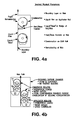
- FIG. 4 a is a diagrammatic view of physical phenomena at the web-to-roll surface
- FIG. 4 b is a diagrammatic view showing applicators on both sides of a traveling web in accordance with an embodiment of the present invention
- FIG. 4 c is a schematic view of an applicator including a transfer roller in accordance with an embodiment of the present invention.
- FIG. 4 d is a schematic view of an applicator enclosure with ventilation in accordance with an embodiment of the present invention.
- FIGS. 5A and 5B are graphical depictions of the cooling and siliconization functions
- FIG. 6 are graphical depictions of prior art solutions to controlling cooling and silicone solids formation
- FIG. 7 are graphical depictions of web cooling load versus total fluid required and silicone solids in mixture in accordance with the present invention.
- FIG. 8A is schematic view of an applicator enclosure with a downward running web in accordance with the present invention.
- FIG. 8B is a schematic view of an applicator with an upward running web in accordance with the present invention.
- the present invention provides a means of passive response to varying evaporative loads, owing to the recovery of water evaporated by the web.
- the cooling load requirement increases, more water must be evaporated as before, but with the means provided of capturing and condensing water vapor, much of the increased cooling requirements are made up by recovered water. Therefore the total fluid required from the initial silicone/water emulsion supply is more nearly constant as shown in the top graph of FIG. 7 , versus the top graph of the prior art case in FIG. 6 . Consequently, a constant silicone concentration supply mixture can be utilized by operators with very little waste of silicone material and good appearance qualities in the printed product.
- FIG. 1 there is shown a conventional applicator for transferring a fluid of a silicone/water mixture to a hot web 10 (the web run could be either upward (as shown), downward or horizontal).
- the web 10 is a material web, typically made of paper that has been printed with ink and subsequently dried in a hot air dryer, such as an air flotation dryer.
- Heat, steam and silicon mist are generated as the web is cooled by evaporation.
- the steam and silicone mist are not directly recovered; they are typically released to ambient or are drawn into the dryer (not shown), or a combination thereof.
- FIG. 2 illustrates an embodiment of the present invention that addresses these problems, such as by capturing the heat, steam and silicone mist within an applicator enclosure 12 , and optionally recovering the captured material for re-use.
- a silicone/water supply is fed to a containment vessel 13 , and an applicator 14 such as a roller is positioned so that a portion of the applicator surface is in contact with the fluid in the vessel 13 .
- the applicator 14 optionally may be cooled such as by supplying a suitable cooling liquid (e.g., water) to the interior of the applicator. This cooling liquid may be recycled through an interior flow path in the applicator and suitable piping.
- a suitable cooling liquid e.g., water
- the applicator 14 may also include a surface treatment to enhance wettability, such as a hydrophilic coating applied by flame spray or sputtering processes to metallic surfaces, or to improve resistance to adhesion of ink solids. Suitable coatings are well known to those skilled in the art and are commercially available, such as from Racine Flame Spray, Inc.
- the direction the applicator 14 rotates is not particularly limited; it can rotate either in the direction of web travel or counter to the direction of web travel.
- One skilled in the art of web handling may prefer a web travel direction, substantially vertical, either in an upward direction, or downward direction in order to best accommodate overall layout of the press line components preceding and following said applicator.
- rotation counter to web travel generally allows more silicone/water mixture to be applied to the web per roller revolution than rotation in the direction of web travel.
- rotation counter to the web travel generally applies less silicone/water mixture to the web per roller revolution than rotation in the direction of travel.
- the speed of the surface speed of the applicator roller as set by the speed of rotation of the applicator roller, is much slower than the web speed.
- the ratio of roller surface speed to web speed is typically in the range of 0.001 to 0.03, though wider ranges are possible.
- a variable speed motor can be used to drive the applicator 14 to obtain the desired amount of silicone to be applied to the web.
- the applicator 14 is preferably completely or substantially enclosed within enclosure 12 , so as to contain the steam and water vapor generated upon evaporation from the web.
- the cooled applicator 14 thus provides a surface or substrate for condensation of the steam and water vapor and carries the condensate and silicone mist back to the vessel 13 .
- FIG. 3 a illustrates the applicator in a web line arrangement following drying in a single or multi-zone dryer 15 .
- the web path exiting the dryer 15 is directed downward, although the invention is not to be so limited.
- the atmosphere inside of the dryer 15 is separated from the water vapor and silicone mist generated in the process of applying a silicone/water mixture to cool the web and provide surface treatment to the web (such as a slip agent) firstly by a seal enclosure comprised of a smoke tunnel 16 fitted to dryer exit roller 21 , and secondly by the applicator enclosure 12 .
- Primary chill roller 21 can be positioned at the exit of the smoke tunnel 16 (coolant connection and tempering control unit for the primary chill roller 21 not shown) to cool the web.
- the coolant supply temperature to chill roller 21 is typically in the range of 15 to 50° C., with 20 to 35° C. being the preferred range.
- two silicone/water applicators 14 , 14 ′ are used, each being a roller and communicating with a respective supply vessel 13 , 13 ′.
- the silicone/water mixture is supplied to the vessels 13 , 13 ′ via a circulating system, including a recirculation pump 17 in fluid communication with a sump tank 18 that receives the silicone/water supply from a suitable source. Excess silicone in the vessels 13 , 13 ′ can be returned to the sump tank as shown.
- Applicator rollers 14 , 14 ′ receive coolant supply flow through feed lines 25 , 25 ′.
- Coolant return lines 26 , 26 ′ conduct spent coolant back to the main coolant return line.
- the coolant supply temperature to applicator rollers 14 , 14 ′ is typically in the range of 10 to 40° C., with 12 to 25° C. being the preferred range.
- a plurality of chill rollers can be placed downstream of the applicators to further cool the web.
- a coolant supply and return, along with a coolant tempering control unit 19 , 19 ′ function to supply suitable coolant to each of the rollers as is known in the art.
- FIG. 3 b illustrates the applicator in a web line arrangement following drying in a single or multi-zone dryer 15 similar to the embodiment of FIG. 3 a , except that the web path exiting the dryer is directed upward.
- liquid from a supply containing water and silicone oil mixture, for example, is applied to a web by at least one applicator.
- Heat from the web evaporates at least a portion of the water and the resulting water vapor is confined to a volume immediately surrounding the at least one applicator by an enclosure.
- the at least one applicator is cooled internally by a coolant media, preferably water, to a temperature preferably within the range of 10 to 40° C.; with 12 to 25° C. being the preferred range to promote recovery of the evaporated water on the applicator surface by condensation, while avoiding buildup of contaminant material such as ink solids on the applicator surface.
- silicone mist that is generated by the function of the applicator, as occurs from the splitting of the liquid film at a location where the web separates from the tangent of the applicator roller surface, can be recovered. Mist is confined and recovered by physical contact with condensed water by means of wetting. Additional cooled rollers within the enclosure can be used to provided additional surface area for condensation and cooling energy to provide maximum recovery of water vapor and silicone mist, as illustrated in FIG. 4 a.
- FIG. 4 b shows an embodiment with additional condenser applicators on both sides of the web and within the enclosure or vapor chamber. Pairs of first and second rollers may be in close contact or may be spaced apart to allow greater time for water evaporation from the web within the span between rollers, as is shown in FIG. 4 a . Silicone fluid, for example, is applied directly to the second applicator 14 by means of liquid film contact with the first applicator 14 a . As in the embodiment of FIG. 4 a , both the first and second applicators of each pair are cooled, such as by an internal coolant flow, in order to provide means of recovering water vapor and silicone mist by condensation and wetting phenomena.
- FIG. 4 c illustrates an embodiment wherein a transfer roller for improved cleanability is provided.
- a cooled pan applicator 14 carries fluid from the pan by means of rotation and transfers the fluid to the transfer roller 24 , but does not directly contact the web 10 .
- the fluid carried by the pan applicator 14 is cooled by contact with the applicator surface prior to being transferred to the transfer roller 24 .
- the transfer roller 24 preferably has a surface treatment in order to enhance the amount of fluid carried on its circumference. This treatment is preferably in the form of macro pores or pockets in the surface of the roller 24 , such as that applied to an anilox roller.
- the macro pores carry excess fluid for keeping the roller surface cool while transferring only a portion of the fluid to the web.
- the transfer roller 24 effectively has a cooled surface capable of promoting the condensation function of the above-mentioned condenser roller of FIG. 4 b , but without the need for a flow path of coolant internal to the roller.
- This transfer roller design allows for simple removal and cleaning of the roller without disconnection of coolant lines and handling the weight of a fluid-filled roller.
- FIG. 4 d illustrates an embodiment where ventilation is included in the enclosure 12 that does not directly connect to the room or to the dryer enclosure, but rather includes a mist elimination device, such as the Air King filter device commercially available from Iowa Distributing Inc. of Cedar Rapids.
- a mist elimination device such as the Air King filter device commercially available from Iowa Distributing Inc. of Cedar Rapids. This feature offers additional flexibility in control of moisture recovery and mist collection.
- At least a portion of the water vapor and silicone mist is removed from the enclosure 12 by withdrawing a regulated airflow from the applicator enclosure 12 and passing that flow through the filtering device 30 .
- the air from the filtering device is then free from harmful contaminants and may be used for make-up air to the room or to the dryer make-up air intake.
- the airflow can be regulated by an airflow damper 31 and vent fan 32 (or a variable speed blower) to withdraw more or less flow, which as described previously, contains water evaporated from the web 10 , thus providing an additional means of moisture regulation independent of the amount of silicone oil that is desired to be applied to the web 10 .
- an airflow damper 31 and vent fan 32 or a variable speed blower
- FIG. 8A discloses a preferred arrangement for a substantially downward running web, which utilizes the web motion to promote the flow of air in a desired flow path, and also encloses a volume immediately following the roll-to-web contact area, that distance along the web path direction being within 200 mm or less.
- a boundary layer of air follows a moving surface, such as a web, owing to the viscous properties of the fluid and the shear forces created by the movement of said surface relative to the bulk volume of fluid.
- the web provides a motive force to impart kinetic energy to said air causing it to flow into the top of the applicator enclosure of FIG. 8A .
- said boundary air is prevented from advancing further in the downward direction as the roller effectively acts as a dam to said boundary flow. Without the upper enclosure of FIG.
- the upper enclosure of FIG. 8A provides a means of passively (without use of a fan or other additional mechanical device to force the air to move) guiding said air over the roller and directing said air downward beyond the silicone pan to a location below the pan, thus preventing the potential of silicone mist from returning upward to the dryer exit opening.
- This upper enclosure creates a flow passage to utilize the kinetic energy of the moving boundary layer to passively conduct the air around the roller and silicone pan and down below applicator assembly, away from the dryer exit.
- the cooled applicator roller provides as ready surface for the recovery of said steam as water by means of rapid condensation.
- the lower baffle of FIG. 8A creates a labyrinth-type seal between said baffle and the web, and establishes a volume confined by the web, applicator roller, pan, fluid in the pan, lower enclosure and said baffle.
- steam generated from the hot web is enclosed and allowed to condense on the cool surface of the pan and said baffle.
- a secondary pan is positioned under the silicone reservoir pan and said baffle to catch said condensed steam and return it as water to the silicone supply source.
- FIG. 8 b shows an embodiment preferred for an upward running web.
- the moving web carries a boundary layer of air, in this case said web travels upward toward the area of web-to-roller contact.
- the roller acts as a dam preventing passage of said boundary air past said web-to-roller contact area.
- an outer enclosure creates a flow passage to utilize the kinetic energy of the moving boundary layer to passively conduct the air under and around the silicone pan and above applicator assembly, away from the dryer exit.
- An upper enclosure provides a labyrinth-type seal between said enclosure and the web, and creates a confined volume bounded by the web, applicator roller, pan, fluid in the pan, and said upper enclosure.
- steam generated from the hot web is enclosed and allowed to condense on the cool surface of the roller, thus recovering the said steam and returning it to the silicone supply source.
Abstract
Description
total fluid×silicone solids concentration=constant
In practice, this function is difficult to carry out in a stable reliable manner, as it requires additional mixing means, sensor and controls, and/or prescribed recipe formulations for water/silicone mixture for each printing condition of incoming web temperature and web weight anticipated. In practice, operators may still apply some excess silicone in general in order to cover the variations and instabilities lacking in the control hardware and/or control of the mixture formulation.
Claims (5)
Priority Applications (1)
| Application Number | Priority Date | Filing Date | Title |
|---|---|---|---|
| US12/449,185 US9016201B2 (en) | 2007-03-23 | 2008-03-10 | Web coating applicator with cooling and material recovery |
Applications Claiming Priority (3)
| Application Number | Priority Date | Filing Date | Title |
|---|---|---|---|
| US91980207P | 2007-03-23 | 2007-03-23 | |
| PCT/US2008/003138 WO2008118284A1 (en) | 2007-03-23 | 2008-03-10 | Web coating applicator with cooling and material recovery |
| US12/449,185 US9016201B2 (en) | 2007-03-23 | 2008-03-10 | Web coating applicator with cooling and material recovery |
Publications (2)
| Publication Number | Publication Date |
|---|---|
| US20100050670A1 US20100050670A1 (en) | 2010-03-04 |
| US9016201B2 true US9016201B2 (en) | 2015-04-28 |
Family
ID=39788807
Family Applications (1)
| Application Number | Title | Priority Date | Filing Date |
|---|---|---|---|
| US12/449,185 Expired - Fee Related US9016201B2 (en) | 2007-03-23 | 2008-03-10 | Web coating applicator with cooling and material recovery |
Country Status (8)
| Country | Link |
|---|---|
| US (1) | US9016201B2 (en) |
| EP (1) | EP2125249A4 (en) |
| JP (1) | JP2010523359A (en) |
| CN (1) | CN101715372A (en) |
| AU (1) | AU2008230080B2 (en) |
| CA (1) | CA2676814C (en) |
| TW (1) | TW200904546A (en) |
| WO (1) | WO2008118284A1 (en) |
Families Citing this family (3)
| Publication number | Priority date | Publication date | Assignee | Title |
|---|---|---|---|---|
| US20110262745A1 (en) * | 2008-11-07 | 2011-10-27 | Sirkku Johanna Ronka | Coated recyclable paper or paperboard and methods for their production |
| CN103996464A (en) * | 2014-06-14 | 2014-08-20 | 芜湖明远电线电缆有限责任公司 | Lubricating device for cable conductor production technology |
| DE202017006204U1 (en) * | 2017-12-01 | 2018-02-28 | Mario Frank | System for the preparation, dosing and application of very precise low-concentration silicone emulsions from highly concentrated silicone emulsions for use in the rewet and coating of printed paper products in offset and gravure presses in the heat and coldset process |
Citations (18)
| Publication number | Priority date | Publication date | Assignee | Title |
|---|---|---|---|---|
| US2556262A (en) | 1946-11-16 | 1951-06-12 | Time Inc | Method of coating paper |
| US2953476A (en) * | 1952-12-18 | 1960-09-20 | British Cotton Ind Res Assoc | Treatment of yarns and the like with liquids |
| US3565039A (en) | 1969-06-25 | 1971-02-23 | Inca Inks | Printing and coating apparatus |
| US3923936A (en) * | 1972-06-12 | 1975-12-02 | Matek Corp | Method of forming an open-celled resilient capillary device |
| DE3241117A1 (en) | 1982-11-06 | 1984-05-10 | Automation für grafische Technik AG, 4005 Meerbusch | Method of cooling a material web printed in a printing machine and device for carrying out this method |
| US4637341A (en) * | 1985-08-28 | 1987-01-20 | Rayco Graphic Manufacturing, Inc. | Apparatus for applying silicone emulsion to a paper web |
| US5471847A (en) | 1993-04-30 | 1995-12-05 | W. R. Grace & Co - Conn. | Web cooling device |
| US5508072A (en) * | 1992-08-11 | 1996-04-16 | E. Khashoggi Industries | Sheets having a highly inorganically filled organic polymer matrix |
| US6082258A (en) * | 1997-06-05 | 2000-07-04 | Harrington; Richard | Printing press damping system |
| US6171653B1 (en) | 1998-01-13 | 2001-01-09 | Voith Sulzer Papiertechnik Patent Gmbh | Apparatus for applying a liquid or viscid coating medium onto a moving fiber material web |
| US6318263B1 (en) | 1999-04-21 | 2001-11-20 | Heidelberger Druckmaschinen Ag | Cooling and moistening unit for rotary printing machines |
| US20020102355A1 (en) * | 1993-05-05 | 2002-08-01 | Levendusky Thomas L. | Apparatus for coating metal strip |
| US20030183099A1 (en) * | 2002-03-28 | 2003-10-02 | Clemens Johannes Maria De Vroome | Applicator roller having a roller jacket, applicator roller and rotating element assembly, dryer, cooling roller stand and printing press having the applicator roller and method for coating a material web |
| US20040173149A1 (en) | 2003-01-30 | 2004-09-09 | Heidelberger Druckmaschinen Ag | Device for applying a liquid mixture to web-shaped printing material |
| US6892642B2 (en) * | 2001-05-15 | 2005-05-17 | Goss International Corporation | Device and method for cooling a material web |
| US6923121B2 (en) | 2001-08-07 | 2005-08-02 | Goss Contiweb B.V. | Apparatus and method for remoistening a product web |
| US7065901B2 (en) | 2000-10-24 | 2006-06-27 | Goss International Iwc | Method and device for cooling a material web |
| US20100009088A1 (en) * | 2005-08-30 | 2010-01-14 | Tore Eriksson | Device and Method for Coating |
-
2008
- 2008-03-10 CA CA2676814A patent/CA2676814C/en not_active Expired - Fee Related
- 2008-03-10 JP JP2010500912A patent/JP2010523359A/en not_active Abandoned
- 2008-03-10 CN CN200880009492A patent/CN101715372A/en active Pending
- 2008-03-10 US US12/449,185 patent/US9016201B2/en not_active Expired - Fee Related
- 2008-03-10 EP EP08742037.8A patent/EP2125249A4/en not_active Withdrawn
- 2008-03-10 WO PCT/US2008/003138 patent/WO2008118284A1/en active Search and Examination
- 2008-03-10 AU AU2008230080A patent/AU2008230080B2/en not_active Ceased
- 2008-03-21 TW TW097110020A patent/TW200904546A/en unknown
Patent Citations (19)
| Publication number | Priority date | Publication date | Assignee | Title |
|---|---|---|---|---|
| US2556262A (en) | 1946-11-16 | 1951-06-12 | Time Inc | Method of coating paper |
| US2953476A (en) * | 1952-12-18 | 1960-09-20 | British Cotton Ind Res Assoc | Treatment of yarns and the like with liquids |
| US3565039A (en) | 1969-06-25 | 1971-02-23 | Inca Inks | Printing and coating apparatus |
| US3923936A (en) * | 1972-06-12 | 1975-12-02 | Matek Corp | Method of forming an open-celled resilient capillary device |
| DE3241117A1 (en) | 1982-11-06 | 1984-05-10 | Automation für grafische Technik AG, 4005 Meerbusch | Method of cooling a material web printed in a printing machine and device for carrying out this method |
| US4637341A (en) * | 1985-08-28 | 1987-01-20 | Rayco Graphic Manufacturing, Inc. | Apparatus for applying silicone emulsion to a paper web |
| US5508072A (en) * | 1992-08-11 | 1996-04-16 | E. Khashoggi Industries | Sheets having a highly inorganically filled organic polymer matrix |
| US5471847A (en) | 1993-04-30 | 1995-12-05 | W. R. Grace & Co - Conn. | Web cooling device |
| US20020102355A1 (en) * | 1993-05-05 | 2002-08-01 | Levendusky Thomas L. | Apparatus for coating metal strip |
| US6082258A (en) * | 1997-06-05 | 2000-07-04 | Harrington; Richard | Printing press damping system |
| US6171653B1 (en) | 1998-01-13 | 2001-01-09 | Voith Sulzer Papiertechnik Patent Gmbh | Apparatus for applying a liquid or viscid coating medium onto a moving fiber material web |
| US6318263B1 (en) | 1999-04-21 | 2001-11-20 | Heidelberger Druckmaschinen Ag | Cooling and moistening unit for rotary printing machines |
| US7065901B2 (en) | 2000-10-24 | 2006-06-27 | Goss International Iwc | Method and device for cooling a material web |
| US6892642B2 (en) * | 2001-05-15 | 2005-05-17 | Goss International Corporation | Device and method for cooling a material web |
| US6923121B2 (en) | 2001-08-07 | 2005-08-02 | Goss Contiweb B.V. | Apparatus and method for remoistening a product web |
| US20030183099A1 (en) * | 2002-03-28 | 2003-10-02 | Clemens Johannes Maria De Vroome | Applicator roller having a roller jacket, applicator roller and rotating element assembly, dryer, cooling roller stand and printing press having the applicator roller and method for coating a material web |
| US6936105B2 (en) | 2002-03-28 | 2005-08-30 | Goss Contiweb B.V. | Applicator roller having a roller jacket, applicator roller and rotating element assembly, dryer, cooling roller stand and printing press having the applicator roller and method for coating a material web |
| US20040173149A1 (en) | 2003-01-30 | 2004-09-09 | Heidelberger Druckmaschinen Ag | Device for applying a liquid mixture to web-shaped printing material |
| US20100009088A1 (en) * | 2005-08-30 | 2010-01-14 | Tore Eriksson | Device and Method for Coating |
Non-Patent Citations (6)
| Title |
|---|
| Australian Communication dated Sep. 12, 2011 in corresponding Australian patent application No. 2008230080. |
| Canadian Communication dated Aug. 1, 2013 in corresponding Canadian patent application No. 2,676,814. |
| Canadian Communication dated Oct. 9, 2012 in corresponding Canadian patent application No. 2,676,814. |
| Chinese Communication dated Sep. 21, 2011 in corresponding foreign patent application No. CN 200880009492.3, 4 pages. |
| European communication mailed Apr. 16, 2014 in corresponding European patent application No. 08742037.8. |
| International Preliminary Examination Report dated Jun. 8, 2010 in corresponding PCT application No. PCT/US08/03138. |
Also Published As
| Publication number | Publication date |
|---|---|
| EP2125249A4 (en) | 2014-05-14 |
| CA2676814A1 (en) | 2008-10-02 |
| TW200904546A (en) | 2009-02-01 |
| EP2125249A1 (en) | 2009-12-02 |
| AU2008230080B2 (en) | 2012-04-26 |
| CN101715372A (en) | 2010-05-26 |
| CA2676814C (en) | 2014-08-12 |
| WO2008118284A1 (en) | 2008-10-02 |
| JP2010523359A (en) | 2010-07-15 |
| AU2008230080A1 (en) | 2008-10-02 |
| US20100050670A1 (en) | 2010-03-04 |
Similar Documents
| Publication | Publication Date | Title |
|---|---|---|
| CN107160850A (en) | A kind of circulated air dries the printing machine of ink | |
| EP0721095B1 (en) | Apparatus for in-line processing of a heated and reacting continuous sheet of material | |
| JP3589697B2 (en) | Web cooling device | |
| US5540152A (en) | Delivery conveyor with control window ventilation and extraction system | |
| US9016201B2 (en) | Web coating applicator with cooling and material recovery | |
| CN101484319A (en) | Method and device for conditioning paper | |
| JP2015513488A (en) | Recording substrate processing apparatus, printing system, and drying method | |
| US6318263B1 (en) | Cooling and moistening unit for rotary printing machines | |
| EP3224054A1 (en) | Recording substrate treatment apparatus, printing system and method of drying | |
| US6923121B2 (en) | Apparatus and method for remoistening a product web | |
| US6775925B2 (en) | Water spray web cooling apparatus for web dryer | |
| US6209456B1 (en) | Web- and sheet-fed printing unit using various ink types, particularly water-based inks | |
| US7006783B2 (en) | Device and method for fixing a toner image by solvent vapor while reducing the solvent drag-out | |
| US20170361626A1 (en) | Coating device | |
| WO2018139189A1 (en) | Impermeable sheet substrate surface drying device, printing device, and printing method | |
| JPH11240126A (en) | Anti-condensing guard | |
| EP2731800A1 (en) | Recirculation system | |
| DE102012021984A1 (en) | Method for indirect applying of pressure fluid to printing ink, in arc flatbed printing machine, involves transferring fluid from carrier to substrate, where fluid comprises low viscosity outside contact region as within region | |
| US6293200B1 (en) | Drying method | |
| CN210617571U (en) | Novel high-speed ink and water printing machine | |
| Moore | The rapid drying of print by microwave energy | |
| DE202021106842U1 (en) | Device for applying at least one layer to a fibrous web | |
| JP2003311925A (en) | Printing machine equipped with drying station | |
| SE427903B (en) | Method and arrangement for covering both sides of a moving material web at two consecutive coating stations |
Legal Events
| Date | Code | Title | Description |
|---|---|---|---|
| AS | Assignment |
Owner name: MEGTEC SYSTEMS, INC.,WISCONSIN Free format text: ASSIGNMENT OF ASSIGNORS INTEREST;ASSIGNORS:ZAGAR, STEVEN;SEIDL, PAUL;ROCHELEAU, MIKE;AND OTHERS;SIGNING DATES FROM 20080307 TO 20080403;REEL/FRAME:023030/0297 Owner name: MEGTEC SYSTEMS, INC., WISCONSIN Free format text: ASSIGNMENT OF ASSIGNORS INTEREST;ASSIGNORS:ZAGAR, STEVEN;SEIDL, PAUL;ROCHELEAU, MIKE;AND OTHERS;SIGNING DATES FROM 20080307 TO 20080403;REEL/FRAME:023030/0297 |
|
| AS | Assignment |
Owner name: BANK OF AMERICA, N.A., AS ADMINISTRATIVE AGENT, CA Free format text: SECURITY INTEREST;ASSIGNOR:MEGTEC SYSTEMS, INC.;REEL/FRAME:033379/0201 Effective date: 20140624 |
|
| STCF | Information on status: patent grant |
Free format text: PATENTED CASE |
|
| AS | Assignment |
Owner name: BANK OF AMERICA, N.A., AS ADMINISTRATIVE AGENT, CA Free format text: SECURITY INTEREST;ASSIGNOR:MEGTEC SYSTEMS, INC.;REEL/FRAME:036139/0178 Effective date: 20150630 |
|
| AS | Assignment |
Owner name: BABCOCK & WILCOX MEGTEC, LLC, WISCONSIN Free format text: CHANGE OF NAME;ASSIGNOR:MEGTEC SYSTEMS, INC.;REEL/FRAME:044144/0654 Effective date: 20161231 |
|
| AS | Assignment |
Owner name: BABCOCK & WILCOX MEGTEC, LLC (F/K/A MEGTEC SYSTEMS Free format text: RELEASE BY SECURED PARTY;ASSIGNOR:BANK OF AMERICA, N.A.;REEL/FRAME:047208/0622 Effective date: 20181005 |
|
| AS | Assignment |
Owner name: BABCOCK & WILCOX MEGTEC, LLC (F/K/A MEGTEC SYSTEMS Free format text: RELEASE BY SECURED PARTY;ASSIGNOR:BANK OF AMERICA, N.A.;REEL/FRAME:047242/0624 Effective date: 20181005 |
|
| FEPP | Fee payment procedure |
Free format text: MAINTENANCE FEE REMINDER MAILED (ORIGINAL EVENT CODE: REM.); ENTITY STATUS OF PATENT OWNER: LARGE ENTITY |
|
| LAPS | Lapse for failure to pay maintenance fees |
Free format text: PATENT EXPIRED FOR FAILURE TO PAY MAINTENANCE FEES (ORIGINAL EVENT CODE: EXP.); ENTITY STATUS OF PATENT OWNER: LARGE ENTITY |
|
| STCH | Information on status: patent discontinuation |
Free format text: PATENT EXPIRED DUE TO NONPAYMENT OF MAINTENANCE FEES UNDER 37 CFR 1.362 |
|
| FP | Lapsed due to failure to pay maintenance fee |
Effective date: 20190428 |