US9018892B2 - Photo-voltaic array fed switched capacitor DC-DC converter based battery charging for Li-Ion batteries - Google Patents
Photo-voltaic array fed switched capacitor DC-DC converter based battery charging for Li-Ion batteries Download PDFInfo
- Publication number
- US9018892B2 US9018892B2 US13/265,619 US201113265619A US9018892B2 US 9018892 B2 US9018892 B2 US 9018892B2 US 201113265619 A US201113265619 A US 201113265619A US 9018892 B2 US9018892 B2 US 9018892B2
- Authority
- US
- United States
- Prior art keywords
- cells
- value
- voltage
- duty cycle
- battery
- Prior art date
- Legal status (The legal status is an assumption and is not a legal conclusion. Google has not performed a legal analysis and makes no representation as to the accuracy of the status listed.)
- Expired - Fee Related, expires
Links
Images


Classifications
-
- H—ELECTRICITY
- H02—GENERATION; CONVERSION OR DISTRIBUTION OF ELECTRIC POWER
- H02J—CIRCUIT ARRANGEMENTS OR SYSTEMS FOR SUPPLYING OR DISTRIBUTING ELECTRIC POWER; SYSTEMS FOR STORING ELECTRIC ENERGY
- H02J7/00—Circuit arrangements for charging or depolarising batteries or for supplying loads from batteries
- H02J7/0013—Circuit arrangements for charging or depolarising batteries or for supplying loads from batteries acting upon several batteries simultaneously or sequentially
- H02J7/0014—Circuits for equalisation of charge between batteries
- H02J7/0016—Circuits for equalisation of charge between batteries using shunting, discharge or bypass circuits
Definitions
- Li-Ion batteries are a popular choice for portable devices such as laptop computers, handheld computers, and similar devices because of their high energy density compared with other types batteries (e.g., Nickel-Cadmium batteries), their low self-discharge cycle, and absence of memory effects resulting in easier maintenance. Li-Ion batteries also have high charge-discharge efficiency (approximately 90%) and a relatively high nominal discharge voltage (e.g., 3.7 V). In applications where a supply voltage needs to be more than what can be obtained from a single battery cell, a battery pack including a plurality of serially-connected cells may be used.
- Li-Ion battery charge/discharge techniques there are several limitations with conventional Li-Ion battery charge/discharge techniques.
- the cell electrolyte breakdown is substantially near a full charge voltage (e.g., 4.2 V).
- Differences in internal impedance, uneven temperature distribution during usage, variations in the manufacturing processes, and aging may result in a difference in the characteristics of individual Li-Ion cells forming a battery during charge and discharge cycles.
- these differences may result in some cells of the serially-connected battery pack becoming charged to the End of Charge (EoC) voltage faster than the remaining cells.
- EoC End of Charge
- Overcharge of these Li-Ion cells may lead to electrolyte fire, thermal runaway, or in a worst case scenario, an explosion.
- Alternative approaches to overcome the limitations of conventional Li-Ion battery charging/discharging techniques may include terminating the charging process as soon as any one cell voltage of the battery pack reaches the EoC voltage to prevent the weaker cells from being overcharged. This approach, in turn, may result in partial charging of the remaining cells in the battery pack lowering the overall battery capacity. To prevent cell reversal and consequent permanent cell damage, the battery may have to be disconnected from the load immediately resulting in the maximum battery capacity not being utilized. The battery capacity may thus be determined by the weakest cell of the battery pack.
- the present disclosure generally describes techniques for photo-voltaic array fed switched capacitor dc-dc converter based battery charging for li-ion batteries.
- a method for balancing and charging a plurality of cells of a battery is described.
- An example method may include selecting a battery cell with a lowest cell voltage for charging, determining if a power source is active, and charging the selected battery cell for a predefined period employing a maximum power point tracking (MPPT) scheme if the power source is active.
- MPPT maximum power point tracking
- Another battery cell may be selected for charging upon the cell voltage of the selected battery reaching a predefined value and/or the predefined period expiring.
- the present disclosure also describes a charging device adapted to balance and charge a battery comprising a plurality of battery cells.
- An example charging device may include a control circuit and a charging circuit.
- the control circuit may be adapted to select a battery cell with a lowest cell voltage for charging, determine if a power source is active, and cause a charging circuit to charge the selected battery cell if the power source is active.
- Another battery cell may be selected to be charged upon the cell voltage of the selected battery reaching a predefined value and/or a predefined period expiring.
- the charging circuit may be adapted to charge the selected battery cell for the predefined period employing a maximum power point tracking (MPPT) scheme.
- MPPT maximum power point tracking
- the present disclosure further describes computer-readable storage medium having instructions stored thereon for controlling a charging device adapted to balance and charge a battery with a plurality of battery cells.
- the instructions may include monitoring a plurality of cells until a cell voltage of at least one battery cell is detected below a predefined value, selecting the battery cell with a lowest cell voltage for charging, determining if a power source is active, and causing the charging device to charge the selected battery cell for a predefined period employing a maximum power point tracking (MPPT) scheme if the power source is active.
- MPPT maximum power point tracking
- Another battery cell may be selected for charging upon the cell voltage of the selected battery reaching the predefined value and/or the predefined period expiring, and a balancing period set for the selected battery cell if the power source is inactive.
- the instructions may also include causing the charging device to perform cell balancing, monitoring cell voltages of the battery cells, and selecting another battery cell for charging upon a cell voltage of a currently charged battery cell reaching the predefined value and/or the
- FIG. 1 illustrates example configurations for a Li-Ion battery charging system according to at least some embodiments
- FIG. 2 illustrates an example diagram depicting deviation of individual cell voltages of weak cells in a series coupled battery pack
- FIG. 3 illustrates a schematic diagram of an example ground isolated switched capacitor dc-dc converter based maximum power point tracking battery charging and cell balancing mechanism
- FIG. 4 illustrates drive signal generation by a power management controller in response to input from control circuit
- FIG. 5 illustrates an example maximum power point tracking by gradually increasing the duty ratio
- FIG. 6 illustrates example variation of power management control signal, power management drive signal, and charging voltage with time
- FIG. 7 illustrates a schematic diagram of a photo-voltaic array fed ground isolated switched capacitor DC-DC converter with power management based on maximum power point tracking (MPPT);
- MPPT maximum power point tracking
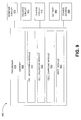
- FIG. 8 illustrates a block diagram of an example photo-voltaic array fed ground isolated switched capacitor converter based cell balancing and battery charging mechanism
- FIG. 9 illustrates an example special purpose processor, which may be used to control a battery charging according to at least some embodiments
- FIG. 10 is a flow diagram illustrating an example method that may be performed by a processor controlling a battery charging device, such as processor 910 in FIG. 9 ;
- FIG. 11 illustrates a flow diagram illustrating an example maximum power point tracking method as part of the process of FIG. 10 that may be performed by a processor controlling a battery charging device, such as processor 910 in FIG. 9 ;
- FIG. 12 illustrates a block diagram of an example computer program product
- This disclosure is generally drawn, inter alia, to methods, apparatus, systems, devices, and/or computer program products related to photo-voltaic array fed switched capacitor dc-dc converter based battery charging for li-ion batteries.
- technologies generally described herein relate to a cell balancing scheme for a serially coupled Li-Ion battery pack supported by a photovoltaic cell array power source.
- a switched capacitor DC-DC converter and a cell monitoring approach may be used to charge and cell balance the battery pack.
- a capacitor charged by the photovoltaic array
- Continuous monitoring for the cells during, charging and discharging may ensure cell voltage changes beyond the predefined limit are detected timely.
- Cell balancing may be performed even in the absence of photovoltaic (PV) array illumination.
- PV photovoltaic
- FIG. 1 illustrates example configurations for a Li-Ion battery charging system, arranged according to at least some embodiments described herein.
- Li-Ion batteries may be used to provide rechargeable power supply to a wide variety of electronic devices.
- electronic devices using Li-Ion batteries may include cameras, media players (audio, video), communication devices (e.g., two-way radios, smart phones), and many more.
- Diagram 100 depicts three example configurations for an example laptop computer.
- device 118 may be coupled to an external battery pack 116 comprising serially coupled battery cells, which in turn may be coupled to a separate charging module 114 .
- the charging module 114 may be configured to receive power to charge the battery pack 116 from a power source 112 .
- Power source 112 may be an Alternative Current (AC) source (e.g., power network), a Direct Current (DC) source (e.g., a vehicle outlet or another battery), a photovoltaic array, and/or some other comparable source.
- AC Alternative Current
- DC Direct Current
- battery pack 116 and charging module 114 may be an integrated part of the device 118 .
- the battery may be an integral part of the computer (albeit removable) and the charging module 114 may be integrated into the circuitry of the computer.
- Power source 112 may be external in this configuration.
- device 118 may include an integrated PV array (e.g., a PV array built on the back of a laptop computer's cover).
- an integrated PV array e.g., a PV array built on the back of a laptop computer's cover.
- the system may be configured to receive DC power from a Power-over-Ethernet (PoE) system to charge the battery pack.
- PoE Power-over-Ethernet
- a system may be adapted to incorporate charging and cell balancing functionalities in the same hardware.
- a power supply voltage may be lower than a battery voltage in a system according to some embodiments.
- the array size may be minimized as the array voltage can be lower than the battery voltage enabling weight reduction and miniaturization of the power source.
- a ground isolated Switched Capacitor (SC) converter may be configured for battery charging and cell balancing allowing avoidance of bulky magnets for energy transfer and isolation. In contrast to passive methods for cell balancing, dissipative elements may not be needed such that simpler and more compact thermal designs are possible.
- battery backup time and battery life may be extended. Battery life may be further extended by ensuring substantially same state of charge (SoC) for all cells through a maximum power point tracking (MPPT) algorithm.
- SoC state of charge
- MPPT maximum power point tracking
- the MPPT algorithm may be utilized to facilitate power source voltage measurements without power source current measurements whereby the need to insert lossy series resistors in the current path may be eliminated such that more power may be extracted for use in PV array applications.
- FIG. 2 illustrates an example diagram depicting deviation of individual cell voltages of weak cells in a series coupled battery pack, arranged according to at least some embodiments described herein.
- dissimilarities in the cells of a serially coupled pack may become more pronounced with increase in the charge-discharge cycles.
- the voltages of three weak cells ( 206 , 208 , and 210 ) of an example battery pack including many cells may start to drift rapidly from the rest of the cell voltages (e.g., 202 and 204 ) just after about five cycles.
- a Photo Voltaic (PV) array fed Switched Capacitor (SC) DC-DC converter based Li-Ion battery charging system may be configured to facilitate charging a battery with a PV array that has a lower voltage than the battery voltage.
- a ground isolated buck type SC DC-DC converter may be configured to generate a floating voltage that is used to charge the cells of a series coupled multi-cell battery pack, one cell at a time.
- a duty cycle of the buck converter may be adjusted to track the array's maximum power point (MPP). Cell voltages may be monitored and active cell balancing performed by charging one cell at a time both during the charge and discharge cycles, which ensures a substantially same state of charge for all cells at all instances.
- cell balancing may be employed.
- the cell balancing scheme may facilitate use of the full battery capacity and prevent limitation of the battery capacity by the capacity of the weakest cell in the serially coupled batter pack.
- Cell balancing may be employed during the charging and/or discharging cycle. During the charging cycle, the cells reaching the EoC voltage earlier than the other cells may be deprived of any further charge current preventing their overcharge. Similarly, during the discharge phase, the cells reaching the EoD voltage earlier than the remaining cells of the pack may be charged so that their voltage falls more slowly than it would have without the cell balancing scheme.
- FIG. 3 illustrates a schematic diagram of an example ground isolated switched capacitor DC-DC converter based maximum power point tracking battery charging and cell balancing mechanism, arranged according to at least some embodiments described herein.
- the example mechanism depicted in diagram 300 assumes an example Li-Ion battery including five serially coupled cells. Embodiments are not limited to the example illustrations, however, and may be implemented with any number of cells.
- the battery voltage V B of the fully charged battery is five times the cell voltage of each cell.
- the charge power may be provided by a solar array with a maximum power point voltage V mp and current I mp , where maximum power point voltage V mp may be below battery voltage V B .
- the power source in diagram 300 is illustrated as a current source 302 .
- the power conversion section 304 may be implemented with a switch SW 1 , and capacitors Cin, C 1 and C 2 .
- Current source 302 initially charges capacitor Cin to some voltage.
- Switch SW 1 may be adapted to first couple capacitor C 1 to capacitor Cin, where the charge stored on Capacitor Cin is transferred to capacitor C 1 , which may charge to the voltage across capacitor Cin. Then, SW 1 may be adapted to decouple capacitor C 1 from capacitor Cin, and couple capacitor C 1 to capacitor C 2 , at which time capacitor C 1 may transfer the stored charge from capacitor C 1 to capacitor C 2 .
- a delay time may be introduced between the time that switch SW 1 is configured to couple capacitor C 1 to capacitor Cin and the time that switch SW 1 is configured to couple capacitor C 1 to capacitor C 2 to ensure that the solar array/battery ground g B is not coupled to the SC converter output ground g sc .
- the isolation of the grounds may ensure that the SC converter output voltage V o is truly floating.
- a PWM generation circuit 306 may be adapted to control the switch SW 1 at a predefined frequency (e.g., 50 kHz).
- the duty cycle of the switch SW 1 may be varied in response to a control signal from the control circuit 312 .
- the control circuit 312 may be configured to scan the voltages of the cells L 1 to L 5 using analog multiplexers 308 and 310 , which can be selectively activated using address from the control circuit 312 .
- Outputs of the analog multiplexers 308 and 310 may be combined at a differential amplifier 311 prior to being provided to the control circuit 312 as input.
- the voltage of cell L 3 may be the lowest voltage among the battery cell voltages.
- the output of the power conversion section 304 may be coupled to cell L 3 by coupling switch SW 2 to 3 and 4 for a predefined period of time (e.g., about two minutes), which may be controllable by control circuits 312 or an external control input.
- Cell L 3 can be charged continuously for this period of time. While the cell is being charged, the charging may be immediately terminated and the control circuit may again scan for another cell with the lowest voltage if the cell voltage is determined to exceed the EoC voltage. If cell L 3 has not yet reached EoC, the charging may be continued for another period of time and then the control circuit 312 may scan the cell voltages to determine the cell with the lowest voltage.
- the next selected cell may then be continuously charged for the predefined period.
- the routine may be repeated until all cells reach the EoC voltage.
- This charging approach ensures that the cells reach the EoC together and at any point of time the SoC of the cells is almost the same.
- Cell balancing and battery charging may, thereby, be ensured with a PV array whose voltage is lower than the battery voltage.
- Cell balancing may also be performed during the battery discharge phase. In the absence of illumination of the power source, the cell balancing may be accomplished by the flying capacitor method using CF, where CF may be first coupled across the entire battery and then discharged into a battery cell with the lowest voltage by selectively activating SW 2 .
- SoC State of Charge
- the power conversion section 304 may be controlled by hardware, software, or a combination of the two.
- a program may be executed by a controller type of device such as a microcontroller or microprocessor, which may be used for the other control functions of the system powered by the batteries.
- a controller type of device such as a microcontroller or microprocessor, which may be used for the other control functions of the system powered by the batteries.
- Such an algorithm may include a loop (as shown in FIG. 10 ) configured to scan cell voltages by setting the appropriate address to the analog multiplexers, checking whether each cell voltage has reached the EoC voltage, and if all cells are charged to the EoC voltage continuing to monitor the voltages of the individual cells.
- MPPT Maximum Power Point Tracking
- Switched Capacitor DC-DC converters can accomplish power conversion with the help of capacitors that are electronically switched between the input power source and the output load.
- the absence of inductors and transformers in SC DC-DC converters can enable lighter weight, smaller space consumption, and/or higher power density.
- the control circuits and switches of an SC DC-DC converter may be fabricated in a single monolithic chip. Due to their compactness, SC DC-DC converters are increasingly used in a wide range of products ranging from mobile phones to portable computers. Some of the other applications of SC converters are charge pump based gate drives and RS 232 level converters for data transfer.
- the introduction of ground isolation in SC DC-DC converters without the use of transformers and inductors can be utilized to enable use of SC DC-DC converters to power noise sensitive low power loads.
- the control circuit 312 may be adapted to monitor each cell's terminal voltage which is an indicator of the cell's SoC. Two analog multiplexers may be used to couple the selected cell to the control circuit 312 through a differential amplifier 311 as discussed above. The cell +ve's may be routed through one of the multiplexers and the cell ⁇ ve's may be routed through the other multiplexer. A desired cell may be selected by an appropriate address from the control circuit 312 , which may execute the software for battery charging, cell balancing and MPPT. Control circuit 312 may be configured to communicate an appropriate address to the analog multiplexers to facilitate the selection of a cell voltage for monitoring, wherein the cell with the lowest cell voltage can be selected for charging. Cells may be balanced in the charge and discharge cycles. MPPT may be achieved by monitoring and computing maximum power point voltage V mp and generating the error signal for duty cycle control.
- a SC DC-DC converter based Li-Ion battery charging and balancing system may be implemented with circuits other than those shown in FIG. 3 (and FIG. 7 ) using the principles described herein. Such circuits may include additional or fewer components. Moreover, the components of the circuits may be embodied using various methods such as MOSFET (Metal Oxide Semiconductor Field Effect Transistor) based switches and/or capacitors, non-MOSFET based switches and/or capacitors, integrated circuits, or various discrete elements, and so on.
- MOSFET Metal Oxide Semiconductor Field Effect Transistor
- FIG. 4 illustrates drive signals that can be generated by a power management controller in response to input from a control circuit, in accordance with at least some embodiments described herein.
- Maximum power point tracking circuits are DC-DC converters that make use of a control circuit to search for the MPP.
- MPP tracking circuits enable extraction of maximum power available from a PV array by transforming the load resistance to the resistance of the array at the maximum power point enabling the array to deliver power to the load at the maximum power point voltage (V mp ) and maximum power point current (I mp ) such that the product V mp ⁇ I mp is maximum.
- a pulse width modulation (PWM) controller may be employed to manage a duty cycle of the DC-DC converter.
- PWM pulse width modulation
- an external error signal generated by the PWM controller may be fed to a comparator 422 of the PWM controller as input.
- the comparator output may be generated after comparison with an internally or externally generated saw tooth waveform.
- two complementary output signals, output 1 and output 2 may be provided to the converter.
- the duty cycle may vary at output 1 (or output 2 ) of the PWM controller in a range from about 0% to about 45% when the input to the comparator 422 generated by the PWM controller varies in another range from about 0.9 V to about 3.4 V with a sensitivity of 2.5% increase/decrease per 0.2V increase/decrease in the control signal (i.e., error signal).
- Diagram 410 illustrates an example saw tooth waveform 412 , an error signal 414 , and a corresponding output signal 416 .
- the duty cycle of the converter may be controlled by the output signal 416 , which is adjusted in response to the incremental change in the error signal 414 .
- FIG. 5 illustrates an example maximum power point tracking by gradually increasing the duty ratio according to at least some embodiments described herein.
- the duty cycle for tracking the MPP of the PV array may depend not only on the incident solar radiation but also on the coupled load.
- MPPT may be performed for each cell of the battery as the terminal voltage and impedance of each cell may be different from one another.
- the duty cycle may be reset initially and then increased in predefined steps by incrementing the error signal to the PWM controller's comparator input shown in FIG. 4 .
- Diagram 500 illustrates waveform 502 of charging current, Isa, vs. charging voltage, V sa .
- the charging voltage can be incrementally increased (by the increase in the duty cycle) such that it may approach MPP voltage 508 .
- the PWM controller may be adapted to measure the charging voltage at each increment and compare against the MPP voltage. If a measured charging voltage ((n ⁇ 1)V sa 506 ) is below maximum power point voltage V mp , the duty cycle may be continued to be incremented. If another measured charging voltage (nV sa 510 ) is determined to be above maximum power point voltage V mp , the duty cycle may be decremented.
- FIG. 6 illustrates example variation of a power management control signal, a power management drive signal, and a charging voltage with time, in accordance with at least some embodiments described herein.
- Diagram 600 shows the charging voltage, V sa 602 , approaching the maximum power point voltage, V mp , over time.
- the duty cycle of the DC-DC converter is incremented through PWM drive signal 604 .
- the duty cycle may be reset to a predefined value (d %) as discussed above, then with each increase in value of the control signal 606 , the duty cycle may be incremented by a fixed amount m (e.g., 2.5%).
- the incremental increase in the duty cycle in turn, may result in the incremental increase in the charging voltage 602 .
- the charging voltage V sa may be measured and compared to the computed maximum power point voltage V mp after a predefined settling time (e.g., about 10 ms).
- the present charging voltage V sa may be about equal to maximum power point voltage V mp , which may result in locking the duty cycle at the present value; (2) the present charging voltage V sa may be less than the computed maximum power point voltage V mp , in which case the duty cycle may be incremented if a maximum limit for the duty ratio has not been reached yet; (3) if the present charging voltage V sa is more than the computed maximum power point voltage V mp and if the previous charging voltage V sa is closer to the maximum power point voltage V mp , then the duty cycle may be decremented by a fixed amount and locked at this point; (4) for some load and panel illumination/temperature conditions, it may not be possible to reach the MPP even when the duty cycle reaches the maximum limit, the duty cycle may be locked at a maximum value in such situations.
- the MPPT algorithm discussed in conjunction with FIG. 11 may address these different conditions.
- FIG. 7 illustrates a schematic diagram of a photo-voltaic array fed ground isolated switched capacitor DC-DC converter with power management based on maximum power point tracking (MPPT), in accordance with at least some embodiments described herein.
- MPPT maximum power point tracking
- a flying capacitor based cell balancing scheme may be activated in the absence of array illumination according to some embodiments.
- cell balancing and charging may occur as discussed in conjunction with FIG. 3 .
- the flying capacitor CF and associated switches QB 1 (e.g., p-channel MOSFET) and QB 2 (e.g., n-channel MOSFET) along with their respective drive circuits (not shown in diagram) may be placed between capacitor C 2 and the second switch SW 2 ( 704 ).
- the presence of capacitor Cin across the PV array symbolized by current source 702 ) may be utilized to ensure that a voltage source V in is available as the input to the SC converter.
- switch SW 1 may be realized with four MOSFETs Q 1 , Q 2 , Q 3 , and Q 4 .
- MOSFETs Q 1 and Q 3 may be p-channel enhancement mode MOSFETs and MOSFETs Q 2 and Q 4 may be n-channel enhancement mode MOSFETs according to one example implementation.
- Capacitors C 1 and C 2 may be implemented as low ESR ceramic capacitors capable of handling large repetitive current surges.
- Switch SW 2 ( 704 ) for coupling the charging circuit to the individual battery cells may include a pair of MOSFETs (e.g., Q 1L1 /Q 2L1 through Q 1L5 /Q 2L5 ) for each switching function.
- a Schottky diode D 1 may be configured to prevent cell discharge into the SC converter output section.
- the control circuit may be configured to selectively activate MOSFETs Q 1L1 (p-channel) and Q 2L1 (n-channel).
- cell L 5 may be assumed to be the weakest during battery discharge in the absence of illumination and its voltage may be assumed to fall at a faster rate than the voltage of the other cells in the battery pack.
- Cell balancing may be performed to boost the voltage of L 5 .
- the cell balancing may be implemented by the flying capacitor method.
- Capacitor CF may be first coupled across the battery by selectively activating the MOSFETs QB 1 and QB 2 with control signals J and K. Charge may be coupled to capacitor CF through MOSFETs QB 1 and QB 2 resulting in capacitor CF charging to a voltage V B .
- the control circuit may turn selectively activate the MOSFETs Q 1L5 and Q 2L5 with gate drives G and H.
- Capacitor CF may discharge via conduction through MOSFET Q 1L5 and Q 2L5 into cell L 5 , such that the voltage of cell L 5 is effectively boosted.
- the process of receiving the charge with the flying capacitor CF from the entire battery and discharging into a particular cell with the lowest cell voltage may be performed at a frequency f for fixed time duration or until the particular cell voltage reaches EoC.
- Switch SW 2 ( 704 ) for coupling the charging circuit to the individual battery cells may include a pair of MOSFETs (e.g., Q 1L1 /Q 2L1 through Q 1L5 /Q 2L5 ).
- a Schottky diode D 1 may be configured to prevent cell discharge into the SC converter output section.
- the control circuit may selectively activate MOSFETs Q 1L1 (p-channel) and Q 2L1 (n-channel).
- SC converter based systems may be better suited for low power systems involving relatively smaller currents.
- two or more SC converters may be operated in parallel in a time-interleaved manner.
- a charge efficiency of a battery may depend on the current at which a battery is being charged. For example, if it takes 10 hours to fully charge a battery at a rate of C/10, it may take more than 20 hours to fully charge the battery at a rate of C/20. This is because the chemistry of the battery is such that it may accept charge at a faster rate when the charging current is higher.
- a depleted battery has to be recharged and readied for the next discharge cycle in the shortest possible time, it may be desirable to charge a battery at a higher current rather than at a lower current.
- charging the battery at a high current rate may amount to charging it with a charge current of 0.5 A (C/4 rate).
- Charging the same battery with a charge current of 0.1 A (C/20 rate) may amount to charging it at a low current rate.
- the voltage may need to be boosted by a factor of about three times with a charge pump, leading to a decrease in the charging current, to charge the battery to 21 V.
- embodiments are not limited to these illustrative example values.
- FIG. 8 illustrates a block diagram of an example photo-voltaic array fed ground isolated switched capacitor converter based cell balancing and battery charging mechanism, arranged according to at least some embodiments described herein.
- the drive from the PWM controller 804 to the p-channel MOSFETs Q 1 and Q 3 may be level shifted (i.e., offset relative to the battery ground) and inverted in logic level (to adjust for different power supplies) at level shifter and inverter 806 , and buffered with a complementary emitter follower 808 , 810 (totem pole) before being applied to the respective gates.
- the PWM controller, inverters, level shifters and totem pole drives collectively shown in dashed lines 802 may be powered from battery voltage V B .
- the control circuit may be configured to selectively activate MOSFETs Q 1L1 (p-channel) and Q 2L1 (n-channel) through opto-coupled totem pole MOSFET drivers 820 / 822 , 826 / 828 , etc. These MOSFETs, along with other similar MOSFETs may constitute an example of switch SW 2 in the circuit of FIG. 7 .
- the drive signal from the control circuit may be provided to MOSFET drive 830 . Circuits within dashed lines 818 and 824 may be powered by the voltage across capacitor C 2 of diagram 700 as described in FIG. 7 .
- a voltage buck type SC DC-DC converter for battery charging and cell balancing may provide a current boost enhancing the battery charge efficiency. Moreover, since cell balancing can be achieved along with cell charging by the same circuit as long as the PV array is illuminated, operating losses due to powering individual circuits may be reduced by not using separate charging and balancing circuits.
- a cell balancing scheme may be adapted to cell balance a serially coupled pack of ultra-capacitors.
- Ultra-capacitors may charge and discharge at a rate that is significantly higher than conventional batteries (e.g., about 30 s compared to an hour in the case of conventional batteries).
- the MOSFET switches may have to be selected to handle larger current surges that may be encountered with ultra-capacitors.
- the charging time and the maximum cell voltage may be altered depending on the cell pack.
- Ultra-capacitors can be coupled together in series/parallel combinations for enhancing the voltage and current capabilities. To ensure long life and prevent premature aging, the voltage across all capacitors may need to be equalized. Unequal voltage distribution among the cells of a capacitor pack may result in more charge being stored in cells charged to a higher voltage and vice versa.
- FIG. 9 illustrates an example special purpose processor, which may be configured to control a battery charging according to at least some embodiments described herein.
- Processor 910 of diagram 900 may be part of a charge module such as charge module 114 of FIG. 1 and manage different circuits associated with charging/balancing of a Li-Ion battery pack employing a cell balancing scheme.
- Processor 910 may include a number of modules configured to control different aspects of charging the Li-Ion battery pack according to some embodiments.
- cell monitoring module 930 may be configured to scan cell voltages of the battery pack through the monitor circuit 972 and activate balancing and/or charging when a cell voltage is determined to drop below a predefined voltage.
- Cell balancing module 940 may be configured to coordinate performance of a cell balancing scheme during the charging and/or discharging cycles through balance circuit 974 .
- the cells reaching the EoC voltage earlier than the other cells may be deprived of any further charge current preventing their overcharge.
- the cells reaching the EoD voltage earlier than the remaining cells of the pack may be charged so that their voltage falls more slowly than it would have without the cell balancing scheme.
- Cell charging module 950 may be configured to manage charging of the battery 980 through charge circuit 976 receiving power from power source 990 , which may be a PV array according to some embodiments.
- MPPT module 960 may be configured to execute an MPPT algorithm while the battery 980 is being charged or discharged adjusting duty cycles to ensure no cell of the battery is overcharged or over excessively discharged relative to optimum full charge and low charge levels, respectively, of the battery's specification.
- Memory 920 may be configured to store instructions for the modules of processor 910 , which may be implemented as hardware, software, or combination of hardware and software.
- Processor 910 may be configured to communicate through electrical couplings or through networked communications with other computing devices and/or data stores.
- Example embodiments may also include methods. These methods can be implemented in any number of ways, including the structures described herein. One such way is by machine operations, of devices of the type described in the present disclosure. Another optional way is for one or more of the individual operations of the methods to be performed in conjunction with one or more human operators performing some of the operations while other operations are performed by machines. These human operators need not be collocated with each other, but each can be only with a machine that performs a portion of the program. In other examples, the human interaction can be automated such as by pre-selected criteria that are machine automated.
- FIG. 10 is a flow diagram illustrating an example method that may be performed by a processor controlling a battery charging device, such as processor 910 in FIG. 9 .
- the operations described in blocks 1002 through 1022 may be stored as computer-executable instructions in a computer-readable medium such as memory 920 of processor 910 and executed by one or more modules of the processor.
- a process of cell balancing based charging of a battery may begin with operation 1002 , “SCAN CELL VOLTAGES.”
- the voltages of the individual cells of a battery such as cells L 1 through L 5 in FIG. 3 may be monitored by a control circuit (e.g., control circuit 312 ).
- decision operation 1004 a determination may be made by control circuit 312 whether the voltage of any cell in the battery is below a predefined voltage. If all cell voltages are determined to be equal or above the predefined voltage at decision operation 1004 , the control circuit may continue monitoring the cell voltages at operation 1002 .
- the process may continue from decision operation 1004 to operation 1006 “SELECT CELL WITH LOWEST VOLTAGE.”
- operation 1006 one of the cells (e.g., L 1 through L 5 ) with lowest detected battery voltage may be selected. Operation 1006 may be followed by decision operation 1008 .
- a determination may be made by a control circuit 312 whether power is still being received from the power source 112 . For example, a PV array may continue providing power as long as it is illuminated. Operation 1012 may follow decision operation 1008 when the power source is determined to be active at decision operation 1008 . Otherwise, operation 1018 may follow decision operation 1008 when the power source is determined to be inactive at decision operation 1008 .
- a charging time may be set for the selected cell by control circuit 312 .
- a charge circuit such as charge circuit 976 of FIG. 9 may charge the cells and monitor the cell voltage employing an MPPT algorithm at operation 1014 “CHARGE CELL & MONITOR (MPPT ALGORITHM).”
- MPPT ALGORITHM CHARGE CELL & MONITOR
- the MPPT algorithm may adjust and lock duty cycles based on measured battery voltages.
- Decision operation 1016 may follow operation 1014 .
- a balancing time may be set for the selected cell by the control circuit 312 .
- Operation 1018 may be followed by operation 1020 , “PERFORM CELL BALANCING WITH FLYING CAPACITOR & MONITOR CELL,” where cell balancing is performed by flying capacitor to ensure cells are not overcharged and not excessively discharged.
- FIG. 11 illustrates a flow diagram illustrating an example maximum power point tracking method as part of the process of FIG. 10 that may be performed by a processor controlling a battery charging device, such as processor 910 in FIG. 9 .
- a process of employing MPPT in charging a Li-Ion battery may begin with operation 1102 , “DETERMINE V oc OF PV SOURCE”, where V oc indicates the open circuit voltage.
- control circuit 312 of FIG. 3 may be adapted to measure an open circuit voltage of the power source 112 with the help of analog multiplexers 308 and 310 , and by decoupling capacitor C 1 from the power source as shown in FIG. 3 .
- the multiplication factor may be chosen differently depending on a type of power source (e.g., different types of solar cells).
- Operation 1104 may be followed by operation 1106 , “RESET DUTY RATIO AND CHARGING VOLTAGE (V sa ).”
- the duty ratio (cycle) of the switched capacitor DC-DC converter type power supply may be reset along with the charging voltage V sa for the battery by control circuit 312 .
- Operation 1106 may be followed by operation 1108 .
- operation 1108 “INCREASE DUTY RATIO BY m %”, the duty ratio may be increased by a predetermined amount by the controller circuit 312 .
- the current charging voltage may be measured after an appropriate settling time at operation 1110 “MEASURE V sapresent AFTER n SEC DELAY (SETTLING TIME).”
- the controller circuit 312 can determine if the duty cycle ratio has reached a maximum limit. If the controller circuit 312 determines that the duty ratio has not yet reached its maximum limit, then decision operation 1116 may be followed by operation 1108 and controller circuit 312 may continue increasing the duty ratio by m % and measuring the charging voltage. If the controller circuit 312 determines that the maximum limit for the duty cycle ratio has been reached, then processing may continue from operation 1116 to operation 1122 , “LOCK DUTY RATIO AT PRESENT VALUE”, where the duty ratio may be locked at its current value by the control circuit 312 .
- the controller circuit 312 can determine if the difference of maximum power point voltage and previous charging voltage is found to be greater than the difference between the maximum power point voltage and the current charging voltage. Processing at operation 1118 may continue to operation 1122 when (V sapresent ⁇ V mp ) ⁇ (V mp ⁇ V saprevious ), where the duty ratio may be locked at its current value by the control circuit 312 . Processing at operation 1118 may continue to operation 1120 when (V sapresent ⁇ V mp ) ⁇ (V mp ⁇ V saprevious ).
- the controller circuit 312 may decrease the duty cycle ratio of the charging circuit by m %. Operation 1120 may be followed by operation 1122 , where the duty ratio may be locked at its current value.
- Battery charging for li-ion batteries employing a photo-voltaic array fed switched capacitor dc-dc converter may be implemented by similar processes with fewer or additional operations. In some examples, the operations may be performed in a different order. In some other examples, various operations may be eliminated. In still other examples, various operations may be divided into additional operations, or combined together into fewer operations.
- FIG. 12 illustrates a block diagram of an example computer program product in accordance with at least some embodiments described herein.
- computer program product 1200 may include a signal bearing medium 1202 that may also include machine readable instructions 1204 that, when executed by, for example, a processor, may provide the functionality described above with respect to FIG. 9 .
- the modules 930 through 960 may undertake one or more of the tasks shown in FIG. 12 in response to instructions 1204 conveyed to processor 910 by medium 1202 to perform actions associated with scanning cell voltages, charging cells employing MPPT algorithm, and balancing cell charging.
- signal bearing medium 1202 depicted in FIG. 12 may encompass a computer-readable medium 1206 , such as, but not limited to, a hard disk drive, a Compact Disc (CD), a Digital Versatile Disk (DVD), a digital tape, memory, etc.
- signal bearing medium 1202 may encompass a recordable medium 1208 , such as, but not limited to, memory, read/write (R/W) CDs, R/W DVDs, etc.
- signal bearing medium 1202 may encompass a communications medium 1210 , such as, but not limited to, a digital and/or an analog communication medium (e.g., a fiber optic cable, a waveguide, a wired communications link, a wireless communication link, etc.).
- a communications medium 1210 such as, but not limited to, a digital and/or an analog communication medium (e.g., a fiber optic cable, a waveguide, a wired communications link, a wireless communication link, etc.).
- computer program product 1200 may be conveyed to one or more modules of the processor 910 by an RF signal bearing medium 1202 , where the signal bearing medium 1202 is conveyed by a wireless communications medium 1210 (e.g., a wireless communications medium conforming with the IEEE 802.11 standard).
- An example method may include monitoring a cell voltage associated with each of the plurality of cells; selecting one of the plurality of cells for charging, where the cell voltage of the selected one of the plurality of cells corresponds to a lowest cell voltage; and determining if a power source is active 1008 or inactive.
- the method may also include charging the selected one of the plurality of cells for a predefined period employing a maximum power point tracking (MPPT) scheme 1014 ; and upon one of: the cell voltage of the selected one of the plurality of cells reaching a predefined value and/or the predefined period expiring 1016 , selecting another one of the plurality of cells for charging.
- MPPT maximum power point tracking
- An example method may further include setting a balancing period for the selected cell 1018 if the power source is determined to be inactive; performing cell balancing 1020 of the selected one of the plurality of cells during the balancing period; and upon one of: the cell voltage of the selected one of the plurality of cells reaching the predefined value and/or the balancing period expiring 1022 , selecting another one of the plurality of cells for charging.
- the MPPT scheme may further include resetting a duty cycle ratio and a charging voltage (V sa ) of a charging circuit 1106 ; and increasing the duty cycle ratio by a predefined percentage 1108 .
- the MPPT scheme may also include measuring a current value of a charging voltage (V sa ) after expiration of a predefined settling period 1110 ; and if the maximum power point voltage (V mp ) is determined to be about equal to the current value of the charging voltage (V sa ), locking the duty cycle ratio 1122 .
- the MPPT scheme may include continuing to increase the duty cycle ratio by the predefined percentage 1108 and continuing to measure the value of the current value of the charging voltage (V sa ) if the current value of the charging voltage (V sa ) is less than the maximum power point voltage (V mp ), and if the duty cycle ratio has not exceeded a predefined limit 1114 , 1116 . If the duty cycle ratio has reached the predefined limit 1116 , the duty cycle ratio 1122 may be locked.
- the MPPT scheme may also include locking the duty cycle ratio 1122 if the current value of the charging voltage (V sa ) is greater than power point voltage (V mp ), and if a difference between the value of the current charging voltage (V sa ) value and the power point voltage (V mp ) is less than a difference between the power point voltage (V mp ) and a previous value of the charging voltage (V sa ) 1118 .
- the power source 112 may be a photo voltaic array and the power source may be active when the photo voltaic array is illuminated.
- the battery 116 may be one of a Lithium-Ion (Li-Ion), a Nickel-Cadmium (Ni—Cd), or a Nickel-metal-hydride (NiMH) battery.
- a charging device 114 adapted to balance and charge a battery 116 comprising a plurality of battery cells.
- An example charging device may include a charging circuit and a control circuit.
- the charging circuit 304 may be adapted to select one of the plurality of battery cells for charging in response to a control signal and charge the selected one of the plurality of battery cells for the predefined period employing a maximum power point tracking (MPPT) scheme 1014 .
- MPPT maximum power point tracking
- the control circuit 312 may be adapted to monitor a cell voltage associated with each of the plurality of battery cells; identify one of the plurality of battery cells for charging, wherein the identified battery cell has a lowest cell voltage among the battery cells; adapt the control signal to select the identified one of the plurality of battery cells; determine if a power source is active 1008 ; if the power source is determined to be active, adapting a charging circuit 304 to charge the selected battery cell (L 1 -L 5 ); and upon one of: the cell voltage of the selected battery cell reaching a predefined value and/or a predefined period expiring 1016 , select another battery cell to be charged.
- control circuit 312 may further be adapted to set a balancing period for the selected battery cell 1018 if the power source is inactive; cause the charging circuit 304 switch to a cell balancing mode 1020 ; monitor cell voltages of the plurality of battery cells 1020 ; and upon one of: the cell voltage of the selected battery cell reaching the predefined value and/or the balancing period expiring 1022 , select another battery cell for charging.
- the control circuit 312 may further be adapted to monitor the plurality of battery cells until the cell voltage of at least one battery cell is detected below the predefined value 1002 , 1004 ; and monitor the cell voltage of the selected battery cell while the selected battery cell is being charged 1014 .
- the control circuit 312 may monitor the cell voltage of the selected battery cell employing a pair of analog multiplexers 308 , 310 and a differential amplifier 311 coupled to outputs of the analog multiplexers.
- the control circuit 312 may also measure a current charging voltage (V sa ) value after a predefined settling period 1110 ; and lock the duty cycle ratio 1122 if the maximum power point voltage (V mp ) is about equal to the current charging voltage (V sa ) value 1112 .
- the control circuit may continue to increase the duty cycle ratio by the predefined percentage 1108 and measure the current charging voltage (V sa ) value 1110 ; and lock the duty cycle ratio 1122 if the duty cycle ratio has reached the predefined limit 1116 .
- the control circuit may lock the duty cycle ratio 1122 .
- the control circuit may decrease the duty cycle ratio by the predefined percentage 1120 and lock the duty cycle ratio 1122 .
- the charging circuit 304 may be a switched capacitor DC-DC converter, and include an input capacitor Cin, a first capacitor C 1 , a second capacitor C 2 , an output capacitor CF, and a first switch SW 1 adapted to couple the first capacitor to the input capacitor and the second capacitor alternatively, and where a delay period is introduced between a phase of the charging circuit where the first capacitor is coupled to the input capacitor and a second phase of the charging circuit where the first capacitor is coupled to the second capacitor such that a charging circuit ground g sc is isolated from a power source ground g B and a battery ground g B .
- the charging circuit may further include a second switch SW 2 adapted to couple the output capacitor CF to the selected battery cell L 1 -L 5 .
- the input capacitor Cin, the first capacitor C 1 , the second capacitor C 2 , the output capacitor CF may be low ESR ceramic capacitors.
- the first switch SW 1 , and the second switch SW 2 may be implemented employing Metal Oxide Semiconductor Field Effect Transistors (MOSFETs).
- MOSFETs Metal Oxide Semiconductor Field Effect Transistors
- At least one of the charging circuit 304 and the control circuit 312 may be integrated with the battery 116 .
- the power source 112 may be a photo voltaic array.
- Example instructions may include monitoring a cell voltage associated with each of the plurality of cells; selecting one of the plurality of cells for charging, where the cell voltage of the selected one of the plurality of cells corresponds to a lowest cell voltage; and determining if a power source is active 1008 or inactive.
- the instructions may also include charging the selected one of the plurality of cells for a predefined period employing a maximum power point tracking (MPPT) scheme 1014 ; and upon one of: the cell voltage of the selected one of the plurality of cells reaching a predefined value and/or the predefined period expiring 1016 , selecting another one of the plurality of cells for charging.
- MPPT maximum power point tracking
- Example instructions may further include setting a balancing period for the selected cell 1018 if the power source is determined to be inactive; performing cell balancing 1020 of the selected one of the plurality of cells during the balancing period; and upon one of: the cell voltage of the selected one of the plurality of cells reaching the predefined value and/or the balancing period expiring 1022 , selecting another one of the plurality of cells for charging.
- the MPPT scheme may further include resetting a duty cycle ratio and a charging voltage (V sa ) of a charging circuit 1106 ; and increasing the duty cycle ratio by a predefined percentage 1108 .
- the MPPT scheme may also include measuring a current value of a charging voltage (V sa ) after expiration of a predefined settling period 1110 ; and if the maximum power point voltage (V mp ) is determined to be about equal to the current value of the charging voltage (V sa ), locking the duty cycle ratio 1122 .
- the MPPT scheme may include continuing to increase the duty cycle ratio by the predefined percentage 1108 and continuing to measure the value of the current value of the charging voltage (V sa ) if the current value of the charging voltage (V sa ) is less than the maximum power point voltage (V mp ), and if the duty cycle ratio has not exceeded a predefined limit 1114 , 1116 . If the duty cycle ratio has reached the predefined limit 1116 , the duty cycle ratio 1122 may be locked.
- the MPPT scheme may also include locking the duty cycle ratio 1122 if the current value of the charging voltage (V sa ) is greater than power point voltage (V mp ), and if a difference between the value of the current charging voltage (V sa ) value and the power point voltage (V mp ) is less than a difference between the power point voltage (V mp ) and a previous value of the charging voltage (V sa ) 1118 .
- the power source 112 may be a photo voltaic array and the power source may be active when the photo voltaic array is illuminated.
- the battery 116 may be a Lithium-Ion (Li-Ion) battery, a Nickel-Cadmium (Ni—Cd), or a Nickel-metal-hydride (NiMH) battery.
- the instructions may be executed by a processor 910 of a portable computing device 128 powered by a Lithium-Ion (Li-Ion) battery 116 that is balanced and charged by the charging device 114 .
- the power source 112 may be a photo-voltaic array integrated into the portable computing device 138 .
- the implementer may opt for a mainly hardware and/or firmware vehicle; if flexibility is paramount, the implementer may opt for a mainly software implementation; or, yet again alternatively, the implementer may opt for some combination of hardware, software, and/or firmware.
- a signal bearing medium examples include, but are not limited to, the following: a recordable type medium such as a floppy disk, a hard disk drive, a Compact Disc (CD), a Digital Video Disk (DVD), a digital tape, a computer memory, etc.; and a transmission type medium such as a digital and/or an analog communication medium (e.g., a fiber optic cable, a waveguide, a wired communications link, a wireless communication link, etc.).
- a typical data processing system generally includes one or more of a system unit housing, a video display device, a memory such as volatile and non-volatile memory, processors such as microprocessors and digital signal processors, computational entities such as operating systems, drivers, graphical user interfaces, and applications programs, one or more interaction devices, such as a touch pad or screen, and/or control systems including feedback loops and control modules (e.g., adjusting setting charge times, setting balancing times, etc.).
- processors such as microprocessors and digital signal processors
- computational entities such as operating systems, drivers, graphical user interfaces, and applications programs
- interaction devices such as a touch pad or screen
- control systems including feedback loops and control modules (e.g., adjusting setting charge times, setting balancing times, etc.).
- a typical data processing system may be implemented utilizing any suitable commercially available components, such as those typically found in data computing/communication and/or network computing/communication systems.
- the herein described subject matter sometimes illustrates different components contained within, or connected with, different other components. It is to be understood that such depicted architectures are merely exemplary, and that in fact many other architectures may be implemented which achieve the same functionality. In a conceptual sense, any arrangement of components to achieve the same functionality is effectively “associated” such that the desired functionality is achieved. Hence, any two components herein combined to achieve a particular functionality may be seen as “associated with” each other such that the desired functionality is achieved, irrespective of architectures or intermediate components.
- any two components so associated may also be viewed as being “operably connected”, or “operably coupled”, to each other to achieve the desired functionality, and any two components capable of being so associated may also be viewed as being “operably couplable”, to each other to achieve the desired functionality.
- operably couplable include but are not limited to physically connectable and/or physically interacting components and/or wirelessly interactable and/or wirelessly interacting components and/or logically interacting and/or logically interactable components.
- a range includes each individual member.
- a group having 1-3 cells refers to groups having 1, 2, or 3 cells.
- a group having 1-5 cells refers to groups having 1, 2, 3, 4, or 5 cells, and so forth.
Abstract
Description
C1=ΔQ/(V in −V o), [1]
and
C2=(I o *t1)/ΔV r, [2]
where t1 is the time period for which C2 supports the load. If t2 is the time period over which C2 is charged by C1 and ΔVr is the output ripple voltage, the charge lost, ΔQ, by capacitor C1 in the time period t2, may be expressed as:
ΔQ=(I o *t2)+(C2*ΔV r). [3]
ΔQ=CF*(V B −V L). [4]
If the process of charge transfer is performed at frequency f, then the current ICB at which cell balancing occurs may be given by:
I CB =f*ΔQ=f*CF*(V B −V L). [5]
Claims (28)
Applications Claiming Priority (3)
| Application Number | Priority Date | Filing Date | Title |
|---|---|---|---|
| IN849/MUM/2011 | 2011-03-23 | ||
| IN849MU2011 | 2011-03-23 | ||
| PCT/IB2011/001169 WO2012127270A1 (en) | 2011-03-23 | 2011-05-30 | Photo-voltaic array fed switched capacitor dc-dc converter based battery charging for li-ion batteries |
Publications (2)
| Publication Number | Publication Date |
|---|---|
| US20130049673A1 US20130049673A1 (en) | 2013-02-28 |
| US9018892B2 true US9018892B2 (en) | 2015-04-28 |
Family
ID=46878675
Family Applications (1)
| Application Number | Title | Priority Date | Filing Date |
|---|---|---|---|
| US13/265,619 Expired - Fee Related US9018892B2 (en) | 2011-03-23 | 2011-05-30 | Photo-voltaic array fed switched capacitor DC-DC converter based battery charging for Li-Ion batteries |
Country Status (2)
| Country | Link |
|---|---|
| US (1) | US9018892B2 (en) |
| WO (1) | WO2012127270A1 (en) |
Cited By (6)
| Publication number | Priority date | Publication date | Assignee | Title |
|---|---|---|---|---|
| US20160056837A1 (en) * | 2014-08-19 | 2016-02-25 | Intersil Americas LLC | System, circuit and method for converting a differential voltage signal including a high common mode voltage component to a ground referenced signal |
| US20170117730A1 (en) * | 2015-06-26 | 2017-04-27 | The Regents Of The University Of California | Efficient supercapacitor charging technique by a hysteretic charging scheme |
| US20180076638A1 (en) * | 2016-09-13 | 2018-03-15 | Mitsumi Electric Co., Ltd. | Battery control circuit |
| US10868344B2 (en) * | 2016-02-25 | 2020-12-15 | Ford Global Technologies, Llc | Entropy driven thermal and electrical management |
| US11070066B2 (en) * | 2019-04-04 | 2021-07-20 | Caterpillar Inc. | Passive battery cell discharge |
| US11374498B2 (en) | 2019-07-19 | 2022-06-28 | Analog Devices International Unlimited Company | Switching converter for power domain separation |
Families Citing this family (19)
| Publication number | Priority date | Publication date | Assignee | Title |
|---|---|---|---|---|
| KR101234059B1 (en) * | 2010-02-22 | 2013-02-15 | 주식회사 엘지화학 | Apparatus and Method for diagnosis of cell balancing unit |
| JP5918961B2 (en) * | 2011-10-07 | 2016-05-18 | 株式会社ケーヒン | Cell balance control device |
| FR2993417B1 (en) * | 2012-07-10 | 2014-07-18 | Batscap Sa | METHOD FOR CHARGING A BATTERY AND BATTERY THUS CHARGED |
| US9583957B2 (en) * | 2012-09-10 | 2017-02-28 | Silicon Works Co., Ltd. | Cell balancing integrated circuit, cell balancing system, and cell balancing method |
| WO2014192015A2 (en) * | 2013-05-03 | 2014-12-04 | Indian Institute Of Technology Bombay | Method and system for a multiport modular pv inverter |
| CN103457313B (en) * | 2013-07-01 | 2015-04-01 | 中国水利水电科学研究院 | Wind and solar general type new energy intelligent control system and method |
| US20150108939A1 (en) * | 2013-10-23 | 2015-04-23 | Neldon P. Johnson | Photovoltaic controller and method for photovoltaic array |
| KR101439059B1 (en) * | 2013-10-29 | 2014-11-04 | 현대자동차주식회사 | Controlling method and apparatus for charging low-voltage battery |
| JP2015171280A (en) | 2014-03-10 | 2015-09-28 | ソニー株式会社 | Voltage equalization device and power storage device |
| WO2015147503A1 (en) * | 2014-03-28 | 2015-10-01 | Samsung Electronics Co., Ltd. | Method for charging battery and electronic device |
| KR20160073486A (en) * | 2014-12-16 | 2016-06-27 | 한국전자통신연구원 | System for charging battery |
| US9812867B2 (en) * | 2015-06-12 | 2017-11-07 | Black Night Enterprises, Inc. | Capacitor enhanced multi-element photovoltaic cell |
| US10377262B2 (en) * | 2016-12-06 | 2019-08-13 | National Chung Shan Institute Of Science And Technology | Range extending apparatus for electric vehicle and control method thereof |
| JP7052326B2 (en) * | 2017-12-05 | 2022-04-12 | 富士通株式会社 | Power supply and communication equipment |
| CN109765960B (en) * | 2019-03-04 | 2020-08-28 | 上海数明半导体有限公司 | Maximum power tracking power generation device and system |
| CN111313117A (en) * | 2020-03-27 | 2020-06-19 | 华霆(合肥)动力技术有限公司 | Lossless passive equalization method and device for battery module and battery system |
| TWI755116B (en) * | 2020-10-26 | 2022-02-11 | 儲盈科技股份有限公司 | Intelligent balanced charging method and system for series battery cells |
| CN112928351A (en) * | 2021-02-10 | 2021-06-08 | 中国科学院金属研究所 | Pulse charging technology of lithium-sulfur battery |
| CN113690962B (en) * | 2021-07-29 | 2024-04-05 | 广东博力威科技股份有限公司 | MPPT control method, device, equipment and storage medium for different input sources |
Citations (27)
| Publication number | Priority date | Publication date | Assignee | Title |
|---|---|---|---|---|
| US4370559A (en) | 1980-12-01 | 1983-01-25 | Langley Jr David T | Solar energy system |
| US4441143A (en) | 1980-08-11 | 1984-04-03 | Gladwin, Inc. | Photo voltaic lighting for outdoor telephone booth |
| US4651080A (en) | 1983-12-29 | 1987-03-17 | John A. Draper | High efficiency battery charging system |
| US4691075A (en) | 1985-09-16 | 1987-09-01 | The United States Of America As Represented By The United States Department Of Energy | Energy conversion system |
| US4695120A (en) | 1985-09-26 | 1987-09-22 | The United States Of America As Represented By The Secretary Of The Army | Optic-coupled integrated circuits |
| US4696359A (en) | 1986-08-22 | 1987-09-29 | National Transducer Corporation | Electronic weighing apparatus |
| US4841416A (en) | 1988-03-02 | 1989-06-20 | Todd Doss | Solar charging lamp |
| US5402303A (en) | 1991-04-18 | 1995-03-28 | Luck; Jonathan M. | Remotely-powdered and remotely-addressed zero-standby-current energy-accumulating high-power solenoid drivers, particularly for systems that are micropowered |
| US5530335A (en) * | 1993-05-11 | 1996-06-25 | Trw Inc. | Battery regulated bus spacecraft power control system |
| US5710504A (en) * | 1996-05-20 | 1998-01-20 | The Board Of Trustees Of The University Of Illinois | Switched capacitor system for automatic battery equalization |
| US5757163A (en) * | 1995-09-29 | 1998-05-26 | Black & Decker Inc. | Battery Charger and method for simultaneously charging multiple batteries from a single power supply |
| US6044698A (en) | 1996-04-01 | 2000-04-04 | Cairo Systems, Inc. | Method and apparatus including accelerometer and tilt sensor for detecting railway anomalies |
| US6057665A (en) | 1998-09-18 | 2000-05-02 | Fire Wind & Rain Technologies Llc | Battery charger with maximum power tracking |
| US6073569A (en) | 1998-02-26 | 2000-06-13 | Murata Electric Boatworks Llc | Advantageous use of battery mass in electric watercraft |
| US6571722B2 (en) | 1998-02-26 | 2003-06-03 | Maruta Electric Boatworks L.L.C. | Computer controlled watercraft |
| US6844703B2 (en) * | 2002-08-14 | 2005-01-18 | The Boeing Company | Battery cell balancing system |
| US6987670B2 (en) | 2003-05-16 | 2006-01-17 | Ballard Power Systems Corporation | Dual power module power system architecture |
| US7180763B2 (en) | 2004-09-21 | 2007-02-20 | Ballard Power Systems Corporation | Power converter |
| US7453232B2 (en) * | 2004-07-06 | 2008-11-18 | Sanyo Electric Co., Ltd. | Leakage detector for a power supply apparatus for a vehicle |
| US7505294B2 (en) | 2003-05-16 | 2009-03-17 | Continental Automotive Systems Us, Inc. | Tri-level inverter |
| US20090079385A1 (en) | 2007-09-21 | 2009-03-26 | Msr Innovations Inc. | Solar powered battery charger using switch capacitor voltage converters |
| US20090206666A1 (en) * | 2007-12-04 | 2009-08-20 | Guy Sella | Distributed power harvesting systems using dc power sources |
| US20090266397A1 (en) | 2008-04-23 | 2009-10-29 | Gm Global Technology Operations, Inc. | Solar battery charging system and optional solar hydrogen production system for vehicle propulsion |
| US7612537B2 (en) | 2007-01-25 | 2009-11-03 | Analog Devices, Inc. | Galvanically isolated charge balance system |
| US7843411B2 (en) * | 2006-01-18 | 2010-11-30 | Manning Ventures, Inc. | Remote cholesteric display |
| DE102009027685A1 (en) | 2009-07-14 | 2011-01-20 | Esg Elektroniksystem- Und Logistik-Gmbh | Solar-powered battery charger |
| US20120256612A1 (en) * | 2009-12-11 | 2012-10-11 | Corinne Alonso | System For The Electronic Management Of Photovoltaic Cells With Adapted Thresholds |
-
2011
- 2011-05-30 US US13/265,619 patent/US9018892B2/en not_active Expired - Fee Related
- 2011-05-30 WO PCT/IB2011/001169 patent/WO2012127270A1/en active Application Filing
Patent Citations (28)
| Publication number | Priority date | Publication date | Assignee | Title |
|---|---|---|---|---|
| US4441143A (en) | 1980-08-11 | 1984-04-03 | Gladwin, Inc. | Photo voltaic lighting for outdoor telephone booth |
| US4370559A (en) | 1980-12-01 | 1983-01-25 | Langley Jr David T | Solar energy system |
| US4651080A (en) | 1983-12-29 | 1987-03-17 | John A. Draper | High efficiency battery charging system |
| US4691075A (en) | 1985-09-16 | 1987-09-01 | The United States Of America As Represented By The United States Department Of Energy | Energy conversion system |
| US4695120A (en) | 1985-09-26 | 1987-09-22 | The United States Of America As Represented By The Secretary Of The Army | Optic-coupled integrated circuits |
| US4696359A (en) | 1986-08-22 | 1987-09-29 | National Transducer Corporation | Electronic weighing apparatus |
| US4841416A (en) | 1988-03-02 | 1989-06-20 | Todd Doss | Solar charging lamp |
| US5402303A (en) | 1991-04-18 | 1995-03-28 | Luck; Jonathan M. | Remotely-powdered and remotely-addressed zero-standby-current energy-accumulating high-power solenoid drivers, particularly for systems that are micropowered |
| US5530335A (en) * | 1993-05-11 | 1996-06-25 | Trw Inc. | Battery regulated bus spacecraft power control system |
| US5757163A (en) * | 1995-09-29 | 1998-05-26 | Black & Decker Inc. | Battery Charger and method for simultaneously charging multiple batteries from a single power supply |
| US6044698A (en) | 1996-04-01 | 2000-04-04 | Cairo Systems, Inc. | Method and apparatus including accelerometer and tilt sensor for detecting railway anomalies |
| US5710504A (en) * | 1996-05-20 | 1998-01-20 | The Board Of Trustees Of The University Of Illinois | Switched capacitor system for automatic battery equalization |
| US6571722B2 (en) | 1998-02-26 | 2003-06-03 | Maruta Electric Boatworks L.L.C. | Computer controlled watercraft |
| US6073569A (en) | 1998-02-26 | 2000-06-13 | Murata Electric Boatworks Llc | Advantageous use of battery mass in electric watercraft |
| US6255804B1 (en) | 1998-09-18 | 2001-07-03 | Fire Wind & Rain Technologies Llc | Method for charging a battery with maximum power tracking |
| US6057665A (en) | 1998-09-18 | 2000-05-02 | Fire Wind & Rain Technologies Llc | Battery charger with maximum power tracking |
| US6844703B2 (en) * | 2002-08-14 | 2005-01-18 | The Boeing Company | Battery cell balancing system |
| US6987670B2 (en) | 2003-05-16 | 2006-01-17 | Ballard Power Systems Corporation | Dual power module power system architecture |
| US7505294B2 (en) | 2003-05-16 | 2009-03-17 | Continental Automotive Systems Us, Inc. | Tri-level inverter |
| US7453232B2 (en) * | 2004-07-06 | 2008-11-18 | Sanyo Electric Co., Ltd. | Leakage detector for a power supply apparatus for a vehicle |
| US7180763B2 (en) | 2004-09-21 | 2007-02-20 | Ballard Power Systems Corporation | Power converter |
| US7843411B2 (en) * | 2006-01-18 | 2010-11-30 | Manning Ventures, Inc. | Remote cholesteric display |
| US7612537B2 (en) | 2007-01-25 | 2009-11-03 | Analog Devices, Inc. | Galvanically isolated charge balance system |
| US20090079385A1 (en) | 2007-09-21 | 2009-03-26 | Msr Innovations Inc. | Solar powered battery charger using switch capacitor voltage converters |
| US20090206666A1 (en) * | 2007-12-04 | 2009-08-20 | Guy Sella | Distributed power harvesting systems using dc power sources |
| US20090266397A1 (en) | 2008-04-23 | 2009-10-29 | Gm Global Technology Operations, Inc. | Solar battery charging system and optional solar hydrogen production system for vehicle propulsion |
| DE102009027685A1 (en) | 2009-07-14 | 2011-01-20 | Esg Elektroniksystem- Und Logistik-Gmbh | Solar-powered battery charger |
| US20120256612A1 (en) * | 2009-12-11 | 2012-10-11 | Corinne Alonso | System For The Electronic Management Of Photovoltaic Cells With Adapted Thresholds |
Non-Patent Citations (20)
| Title |
|---|
| Bentley, W,E, "Cell balancing considerations for lithium-ion battery systems," Twelfth annual battery conference on applications and advances, pp. 223-226, (Jan. 1997). |
| Bonfiglio, C., and Roessler, W., "A cost optimized battery management system with active balancing for lithium ion battery stacks," IEEE Vehicle Power and Propulsion Conference, 2009, VPPC '09, pp. 304-309 (Sep. 7-10, 2009). |
| Chakraborty, S ., et al., "Novel converter topology and algorithm for simultaneous charging and individual cell balancing of multiple Li-ion batteries," 26th Annual International Telecommunications Energy Conference, pp. 248-253 (Sep. 19-23, 2004). |
| Drori, Y., and Martinez, C., "The benefits of cell balancing," Intersil, AN140.0, pp. 1-9 (Jul. 8, 2005). |
| Elias, M.F.M., et al., "Design of smart charger for series lithium-ion batteries," International conference on power electronics and drives systems (PEDS), vol. 2, pp. 1485-1490 (2005). |
| International Search Report and Written Opinion for PCT/IB2011/001169 mailed May 30, 2011. |
| Kimball et al., Increased Performance of Battery Packs by Active Equalization, SmartSpark Energy Systems, Champaign, Illinois, USA, pp. 1-5. |
| M. Zahran, Charge Equalization Unit for a NiCd Battery of Small Earth Observation Satellite EPS Simulation, Proceedings of the 7th WSEAS International Conference on Power Systems, Beijing, China, Sep. 15-17, 2007, 7 pages. |
| Mohamed Azab, A New Maximum Power Point Tracking for Photovoltaic Systems, Nov. 2009, International Journal of Electrical and Electronics Engineering, p. 703. * |
| Moore et al., A review of cell equalization methods for lithium ion and lithium polymer battery systems, Society of automotive engineers, Jan. 2001. |
| Park, H.S., et al., "Individual cell voltage equalizer using selective two current paths for series connected Li-ion battery strings," IEEE Energy conversion congress and exposition, pp, 1812.-1817 (Sep. 20-24, 2009). |
| Park, H.S., et al., "Modularized charge equalization converter with high power density and low voltage stress for HEV lithium-ion battery string," 7th International conference on power electronics, pp. 784-789, (Oct. 2007). |
| Peter, P.K, and Agarwal, V., "Analysis and design of a gound isolated buck switched capacitor dc-dc conveter," IEEE International symposium on industrial electronics, pp. 632-637 (Jul. 2010). |
| S.C Tan, M. Nur, S. Kiratipongvoot, S. Bronstein, Y.M. Lai, C.K. Tse, A. Ioinovici, "Switched Capacitor Converter Configuration with Low EMI Emission Obtained by Interleaving and Its Large Signal Modeling", IEEE International Symposium on Circuits and Systems, pp. 1081-1084, May 2009. |
| Sack, T.T. et al., "Segmented battery charger for high energy 28 v lithium ion attery," IEEE Aerospace and Electronic Systems Magazine, vol. 16 , No. 9, pp. 15-18 (Sep. 2001). |
| Salas, V., et al., "Review of the maximum power point tracking algorithms for stand-alone photovoltaic systems," Solar energy Materials & Solar Cells, vol. 90, Issue 11, pp, 1555-1578 (Jul. 2006). |
| Seeman, M. D., S. R., "Analytical and practical analysis of switched capacitor DC-DC converters," Electrical Engineering and computer science, University of California at Berkley, pp. 66 (Sep. 1, 2006). |
| Specification of Photovoltaic Module, Type: HIP-214NKHE5, Sanyo Electric Co., Ltd., Data Released Sep. 25, 2009, 7 pages. |
| Speltino et al., Cell Equalization in Battery Stacks Through State of ChargeEstimation Polling, 6 pages. |
| Welsh, J. D., "A comparison of active and passive cell balancing techniques for series/parallel battery packs," A thesis presented in partial fulfillment of the requirements for the degree master of science in the graduate school of the Ohio State University, pp. 115 (2009). |
Cited By (8)
| Publication number | Priority date | Publication date | Assignee | Title |
|---|---|---|---|---|
| US20160056837A1 (en) * | 2014-08-19 | 2016-02-25 | Intersil Americas LLC | System, circuit and method for converting a differential voltage signal including a high common mode voltage component to a ground referenced signal |
| US9419644B2 (en) * | 2014-08-19 | 2016-08-16 | Intersil Americas LLC | System, circuit and method for converting a differential voltage signal including a high common mode voltage component to a ground referenced signal for battery voltage managment |
| US20170117730A1 (en) * | 2015-06-26 | 2017-04-27 | The Regents Of The University Of California | Efficient supercapacitor charging technique by a hysteretic charging scheme |
| US10868344B2 (en) * | 2016-02-25 | 2020-12-15 | Ford Global Technologies, Llc | Entropy driven thermal and electrical management |
| US20180076638A1 (en) * | 2016-09-13 | 2018-03-15 | Mitsumi Electric Co., Ltd. | Battery control circuit |
| US10594146B2 (en) * | 2016-09-13 | 2020-03-17 | Mitsumi Electric Co., Ltd. | Battery control circuit for multiple cells employing level shift circuits to avoid fault |
| US11070066B2 (en) * | 2019-04-04 | 2021-07-20 | Caterpillar Inc. | Passive battery cell discharge |
| US11374498B2 (en) | 2019-07-19 | 2022-06-28 | Analog Devices International Unlimited Company | Switching converter for power domain separation |
Also Published As
| Publication number | Publication date |
|---|---|
| WO2012127270A1 (en) | 2012-09-27 |
| US20130049673A1 (en) | 2013-02-28 |
Similar Documents
| Publication | Publication Date | Title |
|---|---|---|
| US9018892B2 (en) | Photo-voltaic array fed switched capacitor DC-DC converter based battery charging for Li-Ion batteries | |
| JP5435124B2 (en) | Rechargeable battery stack power management circuit | |
| US10141551B2 (en) | Battery system | |
| US8796992B2 (en) | Basic unit of lithium-ion battery, battery pack comprising the same, and charge/discharge equalizing method thereof | |
| US20180102664A1 (en) | Battery Charging with Reused Inductor for Boost | |
| EP2891944B1 (en) | Battery stack configuration in a multi-battery supply system | |
| JP6692813B2 (en) | Multi-source power supply system | |
| US20100213897A1 (en) | Battery-Cell Converter Management Systems | |
| US20140203780A1 (en) | System and method for active charge and discharge current balancing in multiple parallel-connected battery packs | |
| AU2019402985B2 (en) | Methods and apparatus for controlling charge current in a battery pack containing cells of disparate types | |
| EP3284156B1 (en) | Battery module and method performed therein | |
| US20130015820A1 (en) | System and method for balancing electrical energy storage devices via differential power bus and capacitive load switched-mode power supply | |
| JP2014176152A (en) | Power storage system | |
| KR101207049B1 (en) | Charging apparatus and method for portable electronic device | |
| JP2011045183A (en) | Charging/discharging device | |
| Liu et al. | New type equalization circuit and management system of Li-ion battery | |
| US20230006450A1 (en) | Power System Configurations for Wireless Charging | |
| US20240030805A1 (en) | Protection circuit, dc-dc converter, battery charger and electric vehicle | |
| US20130221899A1 (en) | Battery charge circuit |
Legal Events
| Date | Code | Title | Description |
|---|---|---|---|
| AS | Assignment |
Owner name: INDIAN INSTITUTE OF TECHNOLOGY BOMBAY, INDIA Free format text: ASSIGNMENT OF ASSIGNORS INTEREST;ASSIGNORS:AGARWAL, VIVEK;PETER, PRADEEP KURUVILLA;REEL/FRAME:027099/0236 Effective date: 20110609 |
|
| STCF | Information on status: patent grant |
Free format text: PATENTED CASE |
|
| CC | Certificate of correction | ||
| FEPP | Fee payment procedure |
Free format text: SURCHARGE FOR LATE PAYMENT, LARGE ENTITY (ORIGINAL EVENT CODE: M1554); ENTITY STATUS OF PATENT OWNER: LARGE ENTITY |
|
| MAFP | Maintenance fee payment |
Free format text: PAYMENT OF MAINTENANCE FEE, 4TH YEAR, LARGE ENTITY (ORIGINAL EVENT CODE: M1551); ENTITY STATUS OF PATENT OWNER: LARGE ENTITY Year of fee payment: 4 |
|
| AS | Assignment |
Owner name: CRESTLINE DIRECT FINANCE, L.P., TEXAS Free format text: SECURITY INTEREST;ASSIGNOR:EMPIRE TECHNOLOGY DEVELOPMENT LLC;REEL/FRAME:048373/0217 Effective date: 20181228 |
|
| AS | Assignment |
Owner name: EMPIRE TECHNOLOGY DEVELOPMENT LLC, WASHINGTON Free format text: RELEASE BY SECURED PARTY;ASSIGNOR:CRESTLINE DIRECT FINANCE, L.P.;REEL/FRAME:049924/0794 Effective date: 20190501 |
|
| FEPP | Fee payment procedure |
Free format text: MAINTENANCE FEE REMINDER MAILED (ORIGINAL EVENT CODE: REM.); ENTITY STATUS OF PATENT OWNER: LARGE ENTITY |
|
| LAPS | Lapse for failure to pay maintenance fees |
Free format text: PATENT EXPIRED FOR FAILURE TO PAY MAINTENANCE FEES (ORIGINAL EVENT CODE: EXP.); ENTITY STATUS OF PATENT OWNER: LARGE ENTITY |
|
| STCH | Information on status: patent discontinuation |
Free format text: PATENT EXPIRED DUE TO NONPAYMENT OF MAINTENANCE FEES UNDER 37 CFR 1.362 |
|
| FP | Lapsed due to failure to pay maintenance fee |
Effective date: 20230428 |