US9018963B2 - Environment sensor - Google Patents
Environment sensor Download PDFInfo
- Publication number
- US9018963B2 US9018963B2 US13/607,459 US201213607459A US9018963B2 US 9018963 B2 US9018963 B2 US 9018963B2 US 201213607459 A US201213607459 A US 201213607459A US 9018963 B2 US9018963 B2 US 9018963B2
- Authority
- US
- United States
- Prior art keywords
- electrode plate
- sensor
- humidity
- sensor portion
- electrostatic capacitance
- Prior art date
- Legal status (The legal status is an assumption and is not a legal conclusion. Google has not performed a legal analysis and makes no representation as to the accuracy of the status listed.)
- Expired - Fee Related, expires
Links
Images


Classifications
-
- G—PHYSICS
- G01—MEASURING; TESTING
- G01N—INVESTIGATING OR ANALYSING MATERIALS BY DETERMINING THEIR CHEMICAL OR PHYSICAL PROPERTIES
- G01N27/00—Investigating or analysing materials by the use of electric, electrochemical, or magnetic means
- G01N27/02—Investigating or analysing materials by the use of electric, electrochemical, or magnetic means by investigating impedance
- G01N27/22—Investigating or analysing materials by the use of electric, electrochemical, or magnetic means by investigating impedance by investigating capacitance
- G01N27/223—Investigating or analysing materials by the use of electric, electrochemical, or magnetic means by investigating impedance by investigating capacitance for determining moisture content, e.g. humidity
-
- G—PHYSICS
- G01—MEASURING; TESTING
- G01D—MEASURING NOT SPECIALLY ADAPTED FOR A SPECIFIC VARIABLE; ARRANGEMENTS FOR MEASURING TWO OR MORE VARIABLES NOT COVERED IN A SINGLE OTHER SUBCLASS; TARIFF METERING APPARATUS; MEASURING OR TESTING NOT OTHERWISE PROVIDED FOR
- G01D5/00—Mechanical means for transferring the output of a sensing member; Means for converting the output of a sensing member to another variable where the form or nature of the sensing member does not constrain the means for converting; Transducers not specially adapted for a specific variable
- G01D5/12—Mechanical means for transferring the output of a sensing member; Means for converting the output of a sensing member to another variable where the form or nature of the sensing member does not constrain the means for converting; Transducers not specially adapted for a specific variable using electric or magnetic means
- G01D5/14—Mechanical means for transferring the output of a sensing member; Means for converting the output of a sensing member to another variable where the form or nature of the sensing member does not constrain the means for converting; Transducers not specially adapted for a specific variable using electric or magnetic means influencing the magnitude of a current or voltage
- G01D5/24—Mechanical means for transferring the output of a sensing member; Means for converting the output of a sensing member to another variable where the form or nature of the sensing member does not constrain the means for converting; Transducers not specially adapted for a specific variable using electric or magnetic means influencing the magnitude of a current or voltage by varying capacitance
- G01D5/2405—Mechanical means for transferring the output of a sensing member; Means for converting the output of a sensing member to another variable where the form or nature of the sensing member does not constrain the means for converting; Transducers not specially adapted for a specific variable using electric or magnetic means influencing the magnitude of a current or voltage by varying capacitance by varying dielectric
-
- G—PHYSICS
- G01—MEASURING; TESTING
- G01N—INVESTIGATING OR ANALYSING MATERIALS BY DETERMINING THEIR CHEMICAL OR PHYSICAL PROPERTIES
- G01N27/00—Investigating or analysing materials by the use of electric, electrochemical, or magnetic means
- G01N27/02—Investigating or analysing materials by the use of electric, electrochemical, or magnetic means by investigating impedance
- G01N27/22—Investigating or analysing materials by the use of electric, electrochemical, or magnetic means by investigating impedance by investigating capacitance
- G01N27/223—Investigating or analysing materials by the use of electric, electrochemical, or magnetic means by investigating impedance by investigating capacitance for determining moisture content, e.g. humidity
- G01N27/225—Investigating or analysing materials by the use of electric, electrochemical, or magnetic means by investigating impedance by investigating capacitance for determining moisture content, e.g. humidity by using hygroscopic materials
-
- G—PHYSICS
- G01—MEASURING; TESTING
- G01K—MEASURING TEMPERATURE; MEASURING QUANTITY OF HEAT; THERMALLY-SENSITIVE ELEMENTS NOT OTHERWISE PROVIDED FOR
- G01K7/00—Measuring temperature based on the use of electric or magnetic elements directly sensitive to heat ; Power supply therefor, e.g. using thermoelectric elements
- G01K7/34—Measuring temperature based on the use of electric or magnetic elements directly sensitive to heat ; Power supply therefor, e.g. using thermoelectric elements using capacitative elements
Definitions
- one object is to provide an environment sensor able to reduce the amount of power consumed.
- the environment sensor includes a sensor portion for detecting a specific physical quantity in the environment; and a power supply portion for applying an AC voltage to the sensor portion, wherein: the sensor portion is structured so as to have an impedance that is higher than a sensor portion of a conventional environment sensor.
- the impedance in the sensor portion to which the AC voltage is applied is higher than that of a conventional environment sensor. As a result, it is possible to reduce the amount of power consumed in the sensor portion when compared to that of a conventional environment sensor.
- the sensor portion is structured including a first electrode plate, a second electrode plate, and a dielectric that is disposed between the first electrode plate and the second electrode plate, so that the electrostatic capacitance between the first electrode plate and the second electrode plate can change in accordance with the specific physical quantity in the environment; the power supply portion applies the AC voltage between the first electrode plate and the second electrode plate; and the distance between the first electrode plate and the second electrode plate, and the surface areas of the first electrode plate and the second electrode plate, are set depending on the impedance of sensor portion.
- the electrostatic capacitance C h of the sensor portion according to examples of the present invention it is possible to cause the electrostatic capacitance C h of the sensor portion according to examples of the present invention to be less than that of the electrostatic capacitance C 1 of the sensor portion of the conventional environment sensor through setting the distance d h and the surface areas S h based on the impedance Z h of the sensor portion, to make it possible to cause the impedance Z h of the sensor portion in the present invention to be higher than the impedance Z 1 of the sensor portion of the conventional environment sensor. This makes it possible to achieve (structure) the environment sensor according to the examples of the present invention easily.
- the surface of the first electrode plate on the dielectric side is formed with a plurality of recessed portions and raised portions.
- the surface of the first electrode plate on the dielectric side is formed with a plurality of recessed portions and raised portions.
- the dielectric swelling and having a reduction (degradation) in sensitivity to humidity in the conventional environment sensor when disposed in a high-humidity environment or when a specific amount of time (months) has elapsed since use Moreover, there has been the risk of delamination (peeling) of the dielectric from the electrode plate due to the stress due to swelling (expansion) of the dielectric.
- the formation of the recessed portions and raised portions in the surface of the first electrode plate on the dielectric side increases the surface area of the surface of the first electrode plate on the dielectric side. Doing so enables a mitigation of the per-unit-surface-area force that acts on the dielectric, when compared to the case wherein the recessed and raised portions are not formed on the surface of the first electrode plate on the dielectric side, not only reducing the likelihood of delamination of the dielectric, but also making it possible to suppress the reduction (degradation) of sensitivity caused by the swelling of the dielectric, thereby enabling stable detection over an extended period of time. Moreover, in particular, this enables an increase in the detection sensitivity of the electrostatic capacitance C h when the surface area S h of the first electrode plate has been set so as to be small, based on the impedance Z h of the sensor portion.
- a coupling layer for bonding the dielectric is further provided on the dielectric side of the first electrode plate.
- This structure further provides a coupling layer, for bonding the dielectric, on the surface of the first electrode plate on the dielectric side. This increases the adhesion between the first electrode plate and the dielectric, thereby not only reducing the likelihood of delamination of the dielectric, but enabling the suppression of the reduction in sensitivity due to swelling of the dielectric. This enables stable detection over an extended period of time.
- a substrate for supporting the first electrode plate is further provided.
- a substrate for supporting the first electrode plate is further provided. This makes it possible to reinforce the mechanical strength of the first electrode plate, and, in particular, is effective when the surface area S h of the first electrode plate is set to be small based on the impedance Z h of the sensor portion.
- a controlling portion for driving the power supply portion intermittently is further provided.
- a controlling portion for driving the power supply portion intermittently is further provided. Doing so enables a further reduction in the amount of electrical power consumed by the environment sensor when compared to the case of driving the power supply portion continuously so as to always supply power to the sensor portion.
- the electrostatic capacitance C h is set so as to be smaller than the electrostatic capacitance C 1 of the conventional environment sensor, based on the impedance Z h of the sensor portion, and thus, if the internal resistance R if is the same, then the time constant ⁇ h of the environment sensor according to the examples of the present invention is smaller than the time constant ⁇ 1 of the conventional environment sensor ( ⁇ h ⁇ 1 ).
- the controlling portion driving intermittently the power supply portion that applies the AC voltage between the first electrode plate and the second electrode plate enables a shortening of the time before reaching a steady state, that is, a shortening of the waiting time (the stabilization time) prior to starting or stopping the sensor portion.
- This makes it possible to reduce the amount of electrical power consumed during this waiting time, enabling a further decrease in the amount of electrical power consumed in the environment sensor according to examples of the present invention, when compared to the conventional environment sensor.
- an interface circuit portion for detecting the electrostatic capacitance which includes the power supply portion, and a communicating portion for sending, to the outside, the electrostatic capacitance detected by the interface circuit portion, are further provided.
- an interface circuit portion for detecting the aforementioned electrostatic capacitance, and a communicating portion for sending, to the outside, the electrostatic capacitance that has been detected, are further provided within the power supply portion.
- an electrostatic capacitance that varies depending on the specific physical quantity is sent to the outside. This makes it possible to communicate (provide notification) the specific physical quantity detected by the sensor portion to a device on the outside.
- the environment sensor according to the examples of the present invention when compared to a conventional environment sensor, is able to reduce the amount of electrical power consumed in the sensor portion. Doing so enables a reduction in the overall amount of electrical power consumed in the environment sensor according to the examples, which includes the sensor portion, when compared to the conventional environment sensor.
- the environment sensor according to the examples of the present invention may be applied well to not only devices with fixed power supplies, but also devices that are supplied with power from mobile power supplies or batteries, energy harvesting devices (environmental electrical power generators) that generate their own electricity through weak energy such as, for example, solar power electric generation, a temperature differential electric generation, vibrational electric generation, bioelectric generation, airflow or wind-power electric generation, hydropower electric generation, wave power electric generation, rotary electric generation, or the like, and also to devices that are provided with mobile fuel cells, and, in particular, to devices that perform wireless communications that are mobile or portable.
- energy harvesting devices environmental electrical power generators
- weak energy such as, for example, solar power electric generation, a temperature differential electric generation, vibrational electric generation, bioelectric generation, airflow or wind-power electric generation, hydropower electric generation, wave power electric generation, rotary electric generation, or the like
- weak energy such as, for example, solar power electric generation, a temperature differential electric generation, vibrational electric generation, bioelectric generation, airflow or wind-power electric generation, hydropower
- FIG. 1 is a block diagram for explaining a humidity sensor in a form of an example.
- FIG. 2 is a graph illustrating one example of changes in voltages over time in intermittent driving.
- FIG. 3 is a graph illustrating one example of currents in voltages over time in intermittent driving.
- FIG. 4 is a perspective diagram for explaining an example of the sensor portion shown in FIG. 1 .
- FIG. 5 is an assembly perspective diagram of the sensor portion shown in FIG. 4 .
- FIG. 6 is a cross-sectional diagram viewed in the direction of the arrow in the line II-II in FIG. 4 .
- FIG. 7 is a cross-sectional diagram viewed in the direction of the arrow in the line III-III in FIG. 4 .
- FIG. 8 is a cross-section sectional diagram for explaining an alternate example of the sensor portion shown in FIG. 4 .
- FIG. 9 is a cross-section sectional diagram for explaining an alternate example of the sensor portion shown in FIG. 4 .
- FIG. 10 is a cross-section sectional diagram for explaining another example of the sensor portion shown in FIG. 4 .
- FIG. 11 is a cross-section sectional diagram for explaining another example of the sensor portion shown in FIG. 4 .
- FIG. 12 is a cross-section sectional diagram for explaining an alternate example of the sensor portion shown in FIG. 10 and FIG. 11 .
- FIG. 13 is a cross-section sectional diagram for explaining an alternate example of the sensor portion shown in FIG. 10 and FIG. 11 .
- FIG. 14 is an enlarged cross-sectional diagram of critical portions of the sensor portion shown in FIG. 4 .
- FIG. 15 is a graph showing the relationship between the relative humidity and the humidity sensitivity factor.
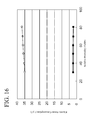
- FIG. 16 is a graph showing the relationship between the relative humidity and power consumption.
- FIG. 1 through FIG. 16 illustrate an example of an environmental sensor according to the present invention.
- a humidity sensor for detecting humidity in the air surrounding the measurement environment is explained as an example of an environment sensor for detecting a specific physical quantity in the environment.
- FIG. 1 is a block diagram for explaining a humidity sensor in an example.
- a humidity sensor 100 is disposed in the environment that is subject to detection, and is for detecting the humidity in the environment (in the atmosphere).
- the humidity sensor 100 is provided with a sensor portion 10 , an interface circuit portion 50 , a controlling portion 70 , and a communicating portion 90 .
- the sensor portion 10 includes a first electrode plate 11 , a second electrode plate 13 , and a humidity-sensitive film 12 disposed between the first electrode plate 11 and the second electrode plate 13 , to function as a capacitor that is able to store charge between the first electrode plate 11 and the second electrode plate 13 .
- the humidity-sensitive film 12 in the present example corresponds to one example of a “dielectric” in the environment sensor according to the present invention.
- the humidity sensitivity factor D h which includes the dielectric constant ⁇ , varies in accordance with the ambient humidity.
- the interface circuit portion 50 includes the power supply portion 30 .
- the power supply portion 30 is connected electrically to the first electrode plate 11 and the second electrode plate 13 , and applies an AC voltage between the first electrode plate 11 and the second electrode plate 13 . Doing so produces an electric current that flows in the sensor portion 10 in accordance with the electrostatic capacitance C h , and the interface circuit portion 50 detects the electrostatic capacitance C h of the sensor portion 10 based on this electric current signal. Moreover, because the electrostatic capacitance C h of the sensor portion 10 varies in accordance with the ambient humidity, this makes it possible to detect the ambient humidity based on the electric current signal.
- f represents the frequency of the AC voltage.
- the ambient humidity can be detected when the power supply portion 30 applies an AC voltage between the first electrode plate 11 and the second electrode plate 13 .
- electrical power is consumed within the sensor portion 10 .
- the electrical power consumption p h (t) is proportional to the inverse of the impedance Z h (that is, is inversely proportional), and thus increasing the value for the impedance Z h decreases the value of the electrical power consumption p h (t), that is, decreases the amount of electrical power consumed.
- the impedance Z h is proportional to the inverse of the frequency f and the electrostatic capacitance C h (that is, inversely proportional), and thus reducing the value of the frequency f and/or the electrostatic capacitance C h increases the impedance Z h .
- Equation (2) not only is the electrostatic capacitance C h proportional to the inverse of the distance d h (that is, inversely proportional), but is proportional to the surface area S h , so the value for the electrostatic capacitance C h is decreased by increasing the distance d h and/or decreasing the surface area S h .
- the sensor portion 10 to which the AC voltage is applied in the present example is structured so that the impedance is higher than in the sensor portion of a conventional environment sensor. As a result, it is possible to reduce the amount of power consumed in the sensor portion 10 when compared to that of a conventional environment sensor.
- the distance d h between the first electrode plate 11 and the second electrode plate 13 , and the surface areas S h of the first electrode plate 11 and the second electrode plate 13 are set based on the impedance Z h of the sensor portion 10 .
- the electrostatic capacitance C h of the sensor portion can be made smaller than the electrostatic capacitance C 1 (C h ⁇ C 1 ), and the impedance Z h of the sensor portion 10 in the examples of the present invention are made higher than the impedance Z 1 of the sensor portion of the conventional humidity sensor (Z h >Z 1 ) through setting the distance d h between the two plates in the humidity sensor 100 according to the present examples to be larger than the distance d 1 (d h >d 1 ), setting the surface areas S h in the humidity sensor 100 according to the present example to be smaller than the surface area S 1 (S h ⁇ S 1
- the electrostatic capacitance C h of the sensor portion 10 according to the present example is less than that of the electrostatic capacitance C 1 of the sensor portion of the conventional humidity sensor through setting the distance d h and the surface areas S h based on the impedance Z h of the sensor portion 10 , to make it possible to cause the impedance Z h of the sensor portion 10 in the present example to be higher than the impedance Z 1 of the sensor portion of the conventional humidity sensor.
- a controlling portion 70 is connected electrically to the interface circuit portion 50 , to output a driving signal with each specific time interval to drive (that is, to start and stop) intermittently the interface circuit portion 50 that includes the power supply portion 30 . Doing so enables a further reduction in the amount of electrical power consumed by the humidity sensor 100 , when compared to the case of the sensor portion 10 wherein the power supply portion 30 is driven continuously so that the sensor portion 10 is always supplied power.
- Equation (7) the voltage e h (t) of the sensor portion 10 is expressed by Equation (7), below:
- E ex represents the effective value of the voltage.
- the time constant is an index that expresses the response speed in the electric signal, and is the time for the voltage signal or current signal to reach about 63.2(%) or about 36.8(%) of the steady-state value.
- the smaller the time constant ⁇ h when intermittently driving the interface circuit portion 50 by the controlling portion 70 the more quickly the sensor portion 10 achieves the steady state.
- FIG. 2 is a graph illustrating one example of the changes in voltage over time in intermittent driving
- FIG. 3 is a graph showing one example of the changes over time in current in intermittent driving.
- the solid lines represent the case wherein the electrostatic capacitance Ch is in the order of tens of pF in the humidity sensor 100 in the present example
- the dotted line represents a case where in the electrostatic capacitance C 1 is in the order of hundreds of pF in the conventional electrostatic capacitance humidity sensor.
- the internal resistances Rif are set identically to be extremely small. As shown in FIG. 2 and FIG.
- FIG. 2 and FIG. 3 show the case wherein the time interval for intermittent driving is in the order of tens of ⁇ s, there is no limitation thereto. Depending on the application, the time interval for intermittent driving may be several seconds, several minutes, or even longer.
- the electrostatic capacitance C h in the humidity sensor 100 according to the present example is set, based on the impedance Z h of the sensor portion 10 , to be smaller than the electrostatic capacitance C 1 of the conventional humidity sensor (that is, C h ⁇ C 1 ), and thus if the internal resistance R if is the same, the time constant ⁇ h of the humidity sensor 100 according to the present example can be smaller than the time constant ⁇ 1 of the conventional humidity sensor (that is, ⁇ h ⁇ 1 ).
- this makes it possible to shorten the time until the steady state is achieved, that is, to shorten the wait time (the stabilization time) until the sensor portion 10 starts up or is stopped, in intermittent driving of the interface circuit portion 50 , which includes the power supply portion 30 , by the controlling portion 70 .
- the communicating portion 90 illustrated in FIG. 1 , is connected electrically to the controlling portion 70 , and inputs, through the controlling portion 70 , the electrostatic capacitance Ch of the sensor portion 10 that has been detected by the interface circuit portion 50 .
- the communicating portion 90 sends the inputted electrostatic capacitance Ch to an external device using either a wireless communication method or a wired communication method.
- the electrostatic capacitance C h which varies in accordance with the ambient humidity, is sent to the outside.
- FIG. 4 is a perspective diagram for explaining an example of the sensor portion 10 shown in FIG. 1
- FIG. 5 is an assembly perspective diagram of the sensor portion 10 illustrated in FIG. 4
- the first electrode plate 11 is disposed on the top face of a substrate 14 , and is supported by the substrate 14 . This enables the mechanical strength of the first electrode plate 11 to be reinforced, and is particularly effective in the case wherein the surface area S h of the first electrode plate 11 is set so as to be small, based on the impedance Z h of the sensor portion 10 .
- the substrate 14 is structured from an insulating material such as, for example, silicon, glass, ceramic, sapphire, quartz, or the like.
- the first electrode plate 11 which includes a first connecting terminal 11 a , and an underlying electrode 15 , which is disposed separated from the first electrode plate 11 , are disposed on the top face of the substrate 14 .
- the first electrode plate 11 is structured from a metal layer comprising at least one layer of platinum/gold/niobium (Pt/Au/Nb), platinum/chrome (Pt/Cr), platinum/niobium (Pt/Nb), platinum/titanium (Pt/Ti), nickel (Ni), aluminum (Al), copper (Cu), or the like.
- the first electrode plate 11 may be formed through, for example, a vapor deposition method, a sputtering method, or the like, to deposit the aforementioned metal layer onto the substrate 14 , followed by patterning, lift-off, or metal masking.
- the thickness of the first electrode plate 11 formed in this way, may be, for example, between several hundred nanometers (or several thousand angstroms) and 1 ⁇ m.
- FIG. 6 is a cross-sectional diagram in the direction of the arrow II-II shown in FIG. 4
- FIG. 7 is a cross-sectional diagram in the direction of the arrow III-III shown in FIG. 4 .
- a plurality of raised portions 11 b is provided on the flat top face of the first electrode plate 11 , to form a plurality of recessed portions and raised portions in the surface that contacts the humidity-sensitive film 12 .
- the plurality of raised portions 11 b is formed using, for example, chemical etching, a dry etching method, including the reactive ion etching (RIE) method, or a micro-machining technology (an MEMS technology), including the lift-off method, or the like.
- chemical etching a dry etching method, including the reactive ion etching (RIE) method, or a micro-machining technology (an MEMS technology), including the lift-off method, or the like.
- RIE reactive ion etching
- MEMS technology micro-machining technology
- FIG. 6 and FIG. 7 show examples wherein a plurality of raised portions 11 b is disposed on the top face of the first electrode plate 11 , there is no limitation thereto. Other structures may be used instead insofar as the result is the formation of a plurality of recessed and raised portions on the surface of the first electrode plate 11 on the humidity-sensitive film 12 side.
- FIG. 8 and FIG. 9 are cross-sectional diagrams for explaining an alternate example of the sensor portion 10 shown in FIG. 4 .
- FIG. 8 is a cross-sectional diagram in the direction of the arrow II-II shown in FIG. 4
- FIG. 9 is a cross-sectional drawing in the direction of the arrow III-III shown in FIG. 4 .
- a plurality of raised portions 14 a may be provided on the top face of the substrate 14 together with the provision of the plurality of raised portions 11 b on the top face of the first electrode plate 11 .
- the raised portions 14 a may be formed using, for example, a chemical etching method, a dry etching method, a reactive ion etching (RIE) method, or a micro-machining technology (an MEMS technology) such as a laser machining method, or a machining technology such as a sandblasting method, a thin film deposition technology such as epitaxial deposition, or a film depositing technology such as vapor deposition or a sputtering method, or the like.
- RIE reactive ion etching
- MEMS technology micro-machining technology
- FIG. 10 and FIG. 11 are cross-sectional diagrams for explaining another example of the sensor portion 10 shown in FIG. 4 .
- FIG. 10 is a cross-sectional diagram in the direction of the arrow II-II shown in FIG. 4
- FIG. 11 is a cross-sectional drawing in the direction of the arrow III-III shown in FIG. 4 .
- a plurality of recessed portions 11 c may be provided, instead of the plurality of raised portions 11 b , on the top face of the first electrode plate 11 .
- similarly recessed portions are formed on the surface of the first electrode plate 11 on the humidity-sensitive film 12 side.
- the recessed portions 11 c may be formed through, for example, a chemical etching method, a dry etching method, a reactive etching (RIE) method, or a micro-machining technology (an MEMS technology) such as the lift-off method.
- RIE reactive etching
- MEMS technology micro-machining technology
- FIG. 12 and FIG. 13 are cross-sectional diagrams for explaining an alternate example of the sensor portion 10 shown in FIG. 10 and FIG. 11 .
- FIG. 12 is a cross-sectional diagram in the direction of the arrow II-II shown in FIG. 4
- FIG. 13 is a cross-sectional drawing in the direction of the arrow III-III shown in FIG. 4 .
- a plurality of recessed portions 14 b may be provided on the top face of the substrate 14 together with the provision of the plurality of recessed portions 11 c on the top face of the first electrode plate 11 .
- the recessed portions 14 b may be formed using, for example, a chemical etching method, a dry etching method, a reactive ion etching (RIE) method, or a micro-machining technology (an MEMS technology) such as a laser machining method, or a machining technology such as a sandblasting method, a thin film deposition technology such as epitaxial deposition, or a film depositing technology such as vapor deposition or a sputtering method, or the like.
- RIE reactive ion etching
- MEMS technology micro-machining technology
- the humidity-sensitive film 12 is provided on the top face of the first electrode plate 11 .
- the humidity-sensitive film swelling and having a reduction (degradation) in sensitivity to humidity in the conventional humidity sensor when disposed in a high-humidity environment or when a specific amount of time (months) has elapsed since use Moreover, there has been the risk of delamination (peeling) of the humidity-sensitive film from the electrode plate due to the stress due to swelling (expansion) of the humidity-sensitive film.
- the humidity sensor 100 according to the present example of the surface area of the face of the first electrode plate 11 on the humidity-sensitive film 12 side is increased through the formation of the recessed portions and raised portions on the top face of the first electrode plate 11 .
- the humidity-sensitive film 12 is structured from, for example, a methyl methacrylate plastic (PMMA), a cross-linked methyl methacrylate plastic, or an organic polymer plastic such as a polyimide, polysulfone, polyether sulfone, or a fluorine-including polyimide.
- PMMA methyl methacrylate plastic
- organic polymer plastic such as a polyimide, polysulfone, polyether sulfone, or a fluorine-including polyimide.
- the thickness of the humidity-sensitive film 12 is between, for example, 1 ⁇ m and 10 ⁇ m.
- the aforementioned organic polymer plastic may first be coated onto the substrate 14 , the first electrode plate 11 , and the underlying electrode 15 through a spin coating method, a dipping method, a spray coating method, or the like, and then dried through performing a heat treatment.
- the organic polymer plastic on top of the first connecting terminal 11 a and the underlying electrode 15 is removed selectively through a vapor-phase reactive ion etching method, a sputtering method, an atmospheric-pressure plasma etching method, or a physical removal method that does not damage the electrode plate, or the like. Doing so forms the humidity-sensitive film 12 and exposes the first connecting terminal 11 a and the underlying electrode 15 .
- the second electrode plate 13 includes a second connecting terminal 13 a , and is disposed on top of the humidity-sensitive film 12 .
- the second connecting terminal 13 a is formed so as to contact the underlying electrode 15 on the substrate 14 .
- the second electrode plate 13 is structured from a metal layer such as, for example, platinum (Pt), gold (Au), chrome (Cr), palladium (Pd), or the like.
- the thickness of the second electrode plate 13 may be, for example, between several hundred nanometers (or several thousand angstroms) and 1 ⁇ m.
- first a patterning method through a film deposition method such as a vapor deposition or a sputtering method, a lift-off method, or a metal masking method, or the like, may be used to deposit a metal film onto the humidity-sensitive film 12 and the substrate 14 .
- the deposited metal film is structured having a porous structure, or with a structure having fine cracks.
- patterning is performed to protect over the first connecting terminal 11 a , and the like, so that the metal film of the second electrode plate 13 selectively does not adhere thereto. Doing so forms both the second electrode plate 13 and the first connecting terminal 11 a.
- a first electrode pad 17 is provided on the exposed first connecting terminal 11 a
- a second electrode pad 18 is provided on the exposed second connecting terminal 13 a .
- the first electrode pad 17 and the second electrode pad 18 are formed using, for example, patterning or metal masking through, for example, a lift-off method, a vapor deposition method, a sputtering method, or the like.
- the material for the electrode pad is a metal film having at least one layer of gold (Au), platinum (Pt), aluminum (Al), copper (Cu), gold/niobium (Au/Nb), gold/chrome (Au/Cr), gold/titanium (Au/Ti), platinum/niobium (Pt/Nb), platinum/chrome (Pt/Cr), platinum/titanium (Pt/Ti), platinum/gold/niobium (Pt/Au/Nb), platinum/gold/chrome (Pt/Au/Cr), or platinum/gold/titanium (Pt/Au/Ti), or the like.
- respective lead lines are connected to the first electrode pad 17 and the second electrode pad 18 . Doing so makes it possible to access (output), as the detection signal, the current that flows between the first electrode plate 11 and the second electrode plate 13 .
- FIG. 14 is an enlarged cross-sectional diagram of critical portions of the sensor portion shown in FIG. 4 .
- a coupling layer 19 is disposed between the first electrode plate 11 and the humidity-sensitive film 12 , and the humidity-sensitive film 12 is adhered to the top surface of the first electrode plate 11 .
- the coupling layer 19 is structured from, for example, a silane coupling agent having, for example, silanol groups (—SiOH) and amino groups (—NH 3 ).
- a plurality of raised portions 11 b may be formed on the top face of the first electrode plate 11 , after which the silane coupling agent may be deposited onto the substrate 14 , the first electrode plate 11 , and the underlying electrode 15 through, for example, a spin coating method, a dipping method, a spray coating method, or the like.
- the coupling layer 19 is formed thereby.
- the silanol groups (—SiOH) of the silane coupling agent have a dehydrating condensing reaction with the silanol groups (—SiOH) on the surface of the first electrode plate 11 , to form covalent bonds (—Si—O—Si—).
- the amino groups (—NH 3 ) of the silane coupling agent react with the humidity-sensitive film 3 .
- the provision of the coupling layer 19 for adhering the humidity-sensitive film 12 to the top surface of the first electrode plate 11 increases the adhesion between the first electrode plate 11 and the humidity-sensitive film 12 , not only decreasing the likelihood that the humidity-sensitive film 12 can delaminate, but also making it possible to suppress the reduction in sensitivity due to swelling of the humidity-sensitive film 12 .
- FIG. 15 is a graph illustrating the relationship between the relative humidity and the humidity sensitivity factor
- FIG. 16 is a graph showing the relationship between the relative humidity and the electrical power consumption.
- the solid lines are the humidity sensor 100 in the present example
- the dotted lines show the case of the conventional humidity sensor.
- a humidity sensor 100 according to the present example and a conventional humidity sensor were placed in a humidity-controllable high-temperature chamber, where the relative humidity was varied while keeping the temperature constant, and an impedance meter was used to set the AC voltage and frequency to specific (constant) values.
- a humidity sensor 100 according to the present example and a conventional humidity sensor were placed in a humidity-controllable high-temperature chamber, where the relative humidity was varied while keeping the temperature constant, and an impedance meter was used to set the AC voltage and frequency to specific (constant) values.
- the humidity sensor 100 according to the present example and the conventional humidity sensor can be seen to have similar humidity sensitivity factors Dh for humidity variations between 30% Rh and 80% Rh, and have identical, or essentially identical, humidity sensitivity characteristics.
- FIG. 15 the humidity sensor 100 according to the present example and the conventional humidity sensor can be seen to have similar humidity sensitivity factors Dh for humidity variations between 30% Rh and 80% Rh, and have identical, or essentially identical, humidity sensitivity characteristics.
- the conventional humidity sensor can be seen to have a tendency for the electrical power consumption to increase from about 35 ⁇ W to about 38 ⁇ W. This can be considered to be because of the increase in the electrostatic capacitance C 1 due to the increase in the humidity sensitivity factor of the dielectric film, illustrated in FIG. 15 , accompanying the increase in humidity, which increases the electric current that flows between the two electrode plates due to the decrease in the impedance in the sensor portion, as shown in Equation (3), above.
- the electrical power consumption showed increases and decreases in the order of hundreds of nW, centered on about 2 ⁇ W.
- the explanation was for a humidity sensor for detecting the humidity in the ambient environment being measured, as an environment sensor for detecting a specific physical quantity in the environment, there is no limitation thereto. Instead, it may be an environment sensor for detecting another physical quantity, where the specific physical quantity is, for example, temperature, pressure, radiation temperature, luminosity, airflow, vibration, inclination, position, ambient gas, dust, or the like.
- the sensor portion 10 to which the AC voltage is applied is structured so as to have higher impedance than in the sensor portion of a conventional humidity sensor.
- the humidity sensor 100 may be applied well to not only devices with fixed power supplies, but also devices that are supplied with power from mobile power supplies or batteries, energy harvesting devices (environmental electrical power generators) that generate their own electricity through weak energy such as, for example, solar power electric generation, a temperature differential electric generation, vibrational electric generation, bioelectric generation, airflow or wind-power electric generation, hydropower electric generation, wave power electric generation, rotary electric generation, or the like, and also to devices that are provided with mobile fuel cells, and, in particular, to devices that perform wireless communications that are mobile or portable.
- energy harvesting devices environmental electrical power generators
- weak energy such as, for example, solar power electric generation, a temperature differential electric generation, vibrational electric generation, bioelectric generation, airflow or wind-power electric generation, hydropower electric generation, wave power electric generation, rotary electric generation, or the like
- weak energy such as, for example, solar power electric generation, a temperature differential electric generation, vibrational electric generation, bioelectric generation, airflow or wind-power electric generation, hydropower electric generation, wave power electric generation
- the distance d h between the first electrode plate 11 and the second electrode plate 13 , and the surface areas S h of the first electrode plate 11 and the second electrode plate 13 are set based on the impedance Z h of the sensor portion 10 .
- the electrostatic capacitance C h of the sensor portion can be made smaller than the electrostatic capacitance C 1 (C h ⁇ C 1 ), and the impedance Z h of the sensor portion 10 in the present invention can be made higher than the impedance Z 1 of the sensor portion of the conventional humidity sensor (Z h >Z 1 ) through setting the distance d h between the two plates in the humidity sensor 100 according to the present example to be larger than the distance d 1 (d h >d 1 ), setting the surface areas S h in the humidity sensor 100 according to the present example to be smaller than the surface area S 1 (S h ⁇ S 1 ),
- the electrostatic capacitance C h of the sensor portion 10 according to the present example is less than that of the electrostatic capacitance C 1 of the sensor portion of the conventional humidity sensor through setting the distance d h and the surface areas S h based on the impedance Z h of the sensor portion 10 , to make it possible to cause the impedance Z h of the sensor portion 10 in the present example to be higher than the impedance Z 1 of the sensor portion of the conventional humidity sensor.
- a plurality of recessed portions and raised portions is formed on the surface of the first electrode plate 11 on the humidity-sensitive film 12 side, that is, on the top surface thereof.
- the humidity-sensitive film swelling and having a reduction (degradation) in sensitivity to humidity in the conventional humidity sensor when disposed in a high-humidity environment or when a specific amount of time (months) has elapsed since use Moreover, there has been the risk of delamination (peeling) of the humidity-sensitive film from the electrode plate due to the stress due to swelling (expansion) of the humidity-sensitive film.
- the surface area of the face of the first electrode plate 11 on the humidity-sensitive film 12 side is increased through the formation of the recessed portions and raised portions on the top face of the first electrode plate 11 . Doing so enables a mitigation of the per-unit-surface-area force that acts on the humidity-sensitive film 12 , when compared to the case wherein the recessed and raised portions are not formed on the top face of the first electrode plate, not only reducing the likelihood of delamination of the humidity-sensitive film 12 , but also making it possible to suppress the reduction (degradation) of sensitivity caused by the swelling of the humidity-sensitive film 12 , thereby enabling stable detection over an extended period of time.
- this enables an increase in the detection sensitivity of the electrostatic capacitance C h when the surface area S h of the first electrode plate 11 has been set so as to be small, based on the impedance Z h of the sensor portion 10 .
- a coupling layer 19 for adhering the humidity-sensitive film 12 to the humidity-sensitive film 12 side of the first electrode plate 11 , that is, to the top surface thereof, is further provided. This increases the adhesion between the first electrode plate 11 and the humidity-sensitive film 12 , thereby not only reducing the likelihood of delamination of the humidity-sensitive film 12 , but enabling the suppression of the reduction in sensitivity due to swelling of the humidity-sensitive film 12 . This enables stable detection over an extended period of time.
- a substrate 14 for supporting the first electrode plate 11 is also provided. This enables the mechanical strength of the first electrode plate 11 to be reinforced, and is particularly effective in the case wherein the surface area S h of the first electrode plate 11 is set so as to be small, based on the impedance Z h of the sensor portion 10 .
- the humidity sensor 140 is further provided with a controlling portion 70 for driving the power supply portion 30 intermittently. Doing so enables a further reduction in the amount of electrical power consumed by the humidity sensor 100 , when compared to the case of the sensor portion 10 wherein the power supply portion 30 is driven continuously so that the sensor portion 10 is always supplied power.
- the electrostatic capacitance C h in the humidity sensor 100 according to the present example is set, based on the impedance Z h of the sensor portion 10 , to be smaller than the electrostatic capacitance C 1 of the conventional humidity sensor (that is, C h ⁇ C 1 ), and thus if the internal resistance R if is the same, the time constant ⁇ h of the humidity sensor 100 according to the present example can be smaller than the time constant ⁇ 1 of the conventional humidity sensor (that is, ⁇ h ⁇ 1 ).
- this makes it possible to shorten the time until the steady state is achieved, that is, to shorten the wait time (the stabilization time) until the sensor portion 10 starts up or is stopped, in intermittent driving of the power supply portion 30 by the controlling portion 70 .
- This makes it possible to reduce the amount of electrical power consumed during this waiting time, enabling a further decrease in the amount of electrical power consumed in the humidity sensor 100 according to the present example, when compared to the conventional humidity sensor.
- the humidity sensor 100 in the present example is provided with an interface circuit portion 50 that includes the power supply portion 30 and that detects the electrostatic capacitance C h of the sensor portion 10 , and a communicating portion 90 for transmitting the electrostatic capacitance C h that is detected by the interface circuit portion 50 .
- the electrostatic capacitance C h which varies in accordance with the ambient humidity, is sent to the outside. This makes it possible to communicate (provide notification) the ambient humidity, detected by the sensor portion 10 , to an external device.
Abstract
Description
C(F)=∈×S/d (1)
C h =D h ×S h /d h (2)
Z h=½πfC h (3)
e h(t)=Z h ·i h(t) (4).
p h(t)=e h(t)·i h(t)=e h(t)2 /Z h (5)
Z if =R if +Z h (6)
Note that Eex represents the effective value of the voltage.
τh =C h ·R if (8).
Claims (6)
Applications Claiming Priority (2)
| Application Number | Priority Date | Filing Date | Title |
|---|---|---|---|
| JP2011196916A JP2013057616A (en) | 2011-09-09 | 2011-09-09 | Environment sensor |
| JP2011-196916 | 2011-09-09 |
Publications (2)
| Publication Number | Publication Date |
|---|---|
| US20130063163A1 US20130063163A1 (en) | 2013-03-14 |
| US9018963B2 true US9018963B2 (en) | 2015-04-28 |
Family
ID=47829301
Family Applications (1)
| Application Number | Title | Priority Date | Filing Date |
|---|---|---|---|
| US13/607,459 Expired - Fee Related US9018963B2 (en) | 2011-09-09 | 2012-09-07 | Environment sensor |
Country Status (4)
| Country | Link |
|---|---|
| US (1) | US9018963B2 (en) |
| JP (1) | JP2013057616A (en) |
| KR (1) | KR20130028650A (en) |
| CN (1) | CN102998345A (en) |
Cited By (9)
| Publication number | Priority date | Publication date | Assignee | Title |
|---|---|---|---|---|
| US10697947B1 (en) | 2019-01-23 | 2020-06-30 | Project Canary, Inc. | Apparatus and methods for reducing fugitive gas emissions at oil facilities |
| US11047753B2 (en) | 2018-12-27 | 2021-06-29 | Therm-O-Disc, Incorporated | Pressure sensor assembly and method for manufacturing a pressure sensor assembly |
| US11346717B2 (en) | 2018-11-13 | 2022-05-31 | Project Canary, Pbc | Air quality monitoring system and method |
| US11366057B2 (en) | 2020-09-10 | 2022-06-21 | Project Canary, Pbc | Air quality monitoring system and method |
| US11573157B2 (en) | 2020-04-03 | 2023-02-07 | Project Canary, Pbc | Air sampling actuator and associated method |
| US11727519B1 (en) | 2023-02-01 | 2023-08-15 | Project Canary, Pbc | Air quality monitors minimization system and methods |
| US11774426B1 (en) | 2022-03-25 | 2023-10-03 | Project Canary, Pbc | Emissions detection system and methods |
| US11861753B1 (en) | 2023-02-01 | 2024-01-02 | Project Canary, Pbc | Air quality monitors minimization system and methods |
| US11887203B1 (en) | 2023-02-01 | 2024-01-30 | Project Canary, Pbc | Air quality monitors minimization system and methods |
Families Citing this family (13)
| Publication number | Priority date | Publication date | Assignee | Title |
|---|---|---|---|---|
| KR101532151B1 (en) * | 2013-12-26 | 2015-06-26 | 삼성전기주식회사 | Humidity sensor and manufacturing method therefor |
| CN104182745B (en) * | 2014-08-15 | 2017-09-22 | 深圳市汇顶科技股份有限公司 | Processing method, system and the fingerprint recognition terminal of fingerprint induced signal |
| EP3078964B1 (en) * | 2015-04-09 | 2017-05-24 | Honeywell International Inc. | Relative humidity sensor and method |
| US9983171B2 (en) * | 2015-07-28 | 2018-05-29 | Ppg Industries Ohio, Inc. | Aerospace transparency having moisture sensors |
| CN105371878B (en) * | 2015-12-04 | 2017-08-25 | 歌尔股份有限公司 | A kind of environmental sensor and its manufacture method |
| CN105628771B (en) * | 2015-12-25 | 2018-06-01 | 北京工业大学 | A kind of direct current electrochemical applications system based on solar cell for supplying power |
| JP2018189481A (en) * | 2017-05-02 | 2018-11-29 | 株式会社リコー | Water content measuring device, measuring method, and image forming apparatus |
| EP3489646A1 (en) * | 2017-11-23 | 2019-05-29 | AT & S Austria Technologie & Systemtechnik Aktiengesellschaft | Determining a physical quantity by means of a native component carrier |
| JP2019120582A (en) * | 2018-01-05 | 2019-07-22 | 株式会社リコー | Characteristic detection device, media supply device, and image forming device |
| WO2019188904A1 (en) * | 2018-03-30 | 2019-10-03 | 住友化学株式会社 | Sensor and production method for same |
| JP7120519B2 (en) * | 2018-07-12 | 2022-08-17 | ミネベアミツミ株式会社 | Humidity sensor and its manufacturing method |
| CN110567607B (en) * | 2019-01-07 | 2020-12-29 | 京东方科技集团股份有限公司 | Temperature sensor, signal acquisition circuit and temperature detection device |
| CN110596472A (en) * | 2019-09-29 | 2019-12-20 | 清华大学 | Dielectric polarization capacitance type electrostatic field measuring method and system |
Citations (17)
| Publication number | Priority date | Publication date | Assignee | Title |
|---|---|---|---|---|
| JPH0572157A (en) | 1991-09-09 | 1993-03-23 | Murata Mfg Co Ltd | Humidity sensing element |
| JPH0694663A (en) | 1992-09-10 | 1994-04-08 | Yamatake Honeywell Co Ltd | Humidity detection element and its manufacture |
| JPH10163445A (en) | 1996-11-29 | 1998-06-19 | Mitsubishi Electric Corp | Method of measuring semiconductor device and manufacturer of semiconductor device |
| JP2001102548A (en) | 1999-07-27 | 2001-04-13 | Applied Materials Inc | Microelectronic device and manufacturing method therefor |
| JP2001249100A (en) | 2000-03-03 | 2001-09-14 | Hioki Ee Corp | Temperature and humidity measuring instrument |
| US6376939B1 (en) * | 1999-04-02 | 2002-04-23 | Sumitomo Chemical Company, Limited | Sensor apparatus and safety apparatus for protecting approach to machines |
| US20030000312A1 (en) * | 2001-06-27 | 2003-01-02 | Atsushi Ono | Pressure sensor |
| US20030057968A1 (en) * | 2001-09-26 | 2003-03-27 | Wang Da Yu | Liquid property sensor |
| US20030179805A1 (en) * | 2002-03-20 | 2003-09-25 | Kazuaki Hamamoto | Capacitance type humidity sensor with passivation layer |
| US20050247114A1 (en) * | 2004-05-07 | 2005-11-10 | Sensicore, Inc. | Multi-sensor system for fluid monitoring with selective exposure of sensors |
| US20060105467A1 (en) * | 2004-11-12 | 2006-05-18 | Niksa Andrew J | MEMS-based sensor for lubricant analysis |
| US20080041792A1 (en) | 2006-08-18 | 2008-02-21 | Martin Crnkovich | Wetness sensor |
| WO2009008237A1 (en) | 2007-07-11 | 2009-01-15 | Yamatake Corporation | Moisture sensing element and method for manufacturing moisture sensing element |
| US20100332156A1 (en) * | 2008-01-31 | 2010-12-30 | Yamatake Corporation | Measurement instrument |
| US20110011179A1 (en) * | 2009-07-16 | 2011-01-20 | Gustafsson Goeran | Moister sensor |
| WO2011046119A1 (en) | 2009-10-16 | 2011-04-21 | 株式会社山武 | Capacitance sensor |
| JP2011094979A (en) | 2009-10-27 | 2011-05-12 | Chino Corp | Capacitive humidity sensor |
Family Cites Families (2)
| Publication number | Priority date | Publication date | Assignee | Title |
|---|---|---|---|---|
| JPS58151549A (en) * | 1982-03-04 | 1983-09-08 | Anritsu Corp | Electrostatic capacity type humidity sensitive element |
| JP2002267364A (en) * | 2001-03-05 | 2002-09-18 | Eku R C Kk | Low humidity chamber with hygrometer |
-
2011
- 2011-09-09 JP JP2011196916A patent/JP2013057616A/en active Pending
-
2012
- 2012-08-07 KR KR1020120086314A patent/KR20130028650A/en active Search and Examination
- 2012-09-04 CN CN2012103240794A patent/CN102998345A/en active Pending
- 2012-09-07 US US13/607,459 patent/US9018963B2/en not_active Expired - Fee Related
Patent Citations (23)
| Publication number | Priority date | Publication date | Assignee | Title |
|---|---|---|---|---|
| JPH0572157A (en) | 1991-09-09 | 1993-03-23 | Murata Mfg Co Ltd | Humidity sensing element |
| JPH0694663A (en) | 1992-09-10 | 1994-04-08 | Yamatake Honeywell Co Ltd | Humidity detection element and its manufacture |
| JPH10163445A (en) | 1996-11-29 | 1998-06-19 | Mitsubishi Electric Corp | Method of measuring semiconductor device and manufacturer of semiconductor device |
| US5846870A (en) | 1996-11-29 | 1998-12-08 | Mitsubishi Denki Kabushiki Kaisha | Method of measuring a semiconductor device and a method of making a semiconductor device |
| US6376939B1 (en) * | 1999-04-02 | 2002-04-23 | Sumitomo Chemical Company, Limited | Sensor apparatus and safety apparatus for protecting approach to machines |
| JP2001102548A (en) | 1999-07-27 | 2001-04-13 | Applied Materials Inc | Microelectronic device and manufacturing method therefor |
| US6313033B1 (en) | 1999-07-27 | 2001-11-06 | Applied Materials, Inc. | Ionized metal plasma Ta, TaNx, W, and WNx liners for gate electrode applications |
| JP2001249100A (en) | 2000-03-03 | 2001-09-14 | Hioki Ee Corp | Temperature and humidity measuring instrument |
| US20030000312A1 (en) * | 2001-06-27 | 2003-01-02 | Atsushi Ono | Pressure sensor |
| US20030057968A1 (en) * | 2001-09-26 | 2003-03-27 | Wang Da Yu | Liquid property sensor |
| US20030179805A1 (en) * | 2002-03-20 | 2003-09-25 | Kazuaki Hamamoto | Capacitance type humidity sensor with passivation layer |
| US20050247114A1 (en) * | 2004-05-07 | 2005-11-10 | Sensicore, Inc. | Multi-sensor system for fluid monitoring with selective exposure of sensors |
| US20060105467A1 (en) * | 2004-11-12 | 2006-05-18 | Niksa Andrew J | MEMS-based sensor for lubricant analysis |
| US20080041792A1 (en) | 2006-08-18 | 2008-02-21 | Martin Crnkovich | Wetness sensor |
| CN101505812A (en) | 2006-08-18 | 2009-08-12 | 弗雷泽纽斯医疗保健控股有限公司 | Wetness sensor |
| US20090322543A1 (en) | 2006-08-18 | 2009-12-31 | Fresenius Medical Care Holding, Inc. | Wetness sensor |
| WO2009008237A1 (en) | 2007-07-11 | 2009-01-15 | Yamatake Corporation | Moisture sensing element and method for manufacturing moisture sensing element |
| JP2009019964A (en) | 2007-07-11 | 2009-01-29 | Yamatake Corp | Humidity detection element and its manufacturing method |
| US20100332156A1 (en) * | 2008-01-31 | 2010-12-30 | Yamatake Corporation | Measurement instrument |
| US20110011179A1 (en) * | 2009-07-16 | 2011-01-20 | Gustafsson Goeran | Moister sensor |
| WO2011046119A1 (en) | 2009-10-16 | 2011-04-21 | 株式会社山武 | Capacitance sensor |
| US20120206147A1 (en) | 2009-10-16 | 2012-08-16 | Azbil Corporation | Electrostatic capacitive sensor |
| JP2011094979A (en) | 2009-10-27 | 2011-05-12 | Chino Corp | Capacitive humidity sensor |
Non-Patent Citations (7)
| Title |
|---|
| Chinese Office Action dated Apr. 22, 2014, from corresponding Chinese Application No. 201210324079.4. |
| De-Liang Ning , et al. "Structure design of novel type capacitance sensor for steam humidity" 2007, Transducer and Microsystem Technologies 26(3), pp. 65-67, 72. |
| Japanese Office Action dated Oct. 10, 2014, which issued during prosecution of Japanese Application No. 2011-196916, which corresponds to the present application. |
| Jia Liu, et al. "Structural optimization of capacitive humidity sensor" 2009, Applied Science and Technology, vol. 36, No. 6, pp. 43-44, 52. |
| Korean Office Action dated Sep. 24, 2014, which issued during prosecution of Korean Application No. 10-2012-0086314, which corresponds to the present application. |
| Wenshun Meng, et al. "Principle and Application of Capacity Sensor" 2003, Modern Electronic Technique, pp. 78-81. |
| WO 2011046119 Machine Translation. * |
Cited By (26)
| Publication number | Priority date | Publication date | Assignee | Title |
|---|---|---|---|---|
| US11467032B2 (en) | 2018-11-13 | 2022-10-11 | Project Canary, Pbc | Air quality monitoring system and method |
| US11788889B1 (en) | 2018-11-13 | 2023-10-17 | Project Canary, Pbc | Air quality monitoring system and method |
| US11604094B2 (en) | 2018-11-13 | 2023-03-14 | Project Canary, Pbc | Air quality monitoring system and method |
| US11346717B2 (en) | 2018-11-13 | 2022-05-31 | Project Canary, Pbc | Air quality monitoring system and method |
| US11768110B2 (en) | 2018-11-13 | 2023-09-26 | Project Canary, Pbc | Air quality monitoring system and method |
| US11047753B2 (en) | 2018-12-27 | 2021-06-29 | Therm-O-Disc, Incorporated | Pressure sensor assembly and method for manufacturing a pressure sensor assembly |
| US11408870B2 (en) | 2019-01-23 | 2022-08-09 | Project Canary, Pbc | Apparatus and methods for reducing fugitive gas emissions at oil facilities |
| US11892437B2 (en) | 2019-01-23 | 2024-02-06 | Project Canary, Pbc | Apparatus and methods for reducing fugitive gas emissions at oil facilities |
| US11215593B2 (en) | 2019-01-23 | 2022-01-04 | Project Canary, Pbc | Apparatus and methods for reducing fugitive gas emissions at oil facilities |
| US10697947B1 (en) | 2019-01-23 | 2020-06-30 | Project Canary, Inc. | Apparatus and methods for reducing fugitive gas emissions at oil facilities |
| US11662336B2 (en) | 2019-01-23 | 2023-05-30 | Project Canary, Pbc | Apparatus and methods for reducing fugitive gas emissions at oil facilities |
| US11782035B2 (en) | 2019-01-23 | 2023-10-10 | Project Canary, Pbc | Apparatus and methods for reducing fugitive gas emissions at oil facilities |
| US11733221B2 (en) | 2019-01-23 | 2023-08-22 | Project Canary, Pbc | Apparatus and methods for reducing fugitive gas emissions at oil facilities |
| US11573157B2 (en) | 2020-04-03 | 2023-02-07 | Project Canary, Pbc | Air sampling actuator and associated method |
| US11781979B1 (en) | 2020-09-10 | 2023-10-10 | Project Canary, Pbc | Air quality monitoring system and method |
| US11754495B2 (en) | 2020-09-10 | 2023-09-12 | Project Canary, Pbc | Air quality monitoring system and method |
| US11592390B2 (en) | 2020-09-10 | 2023-02-28 | Project Canary, Pbc | Air quality monitoring system and method |
| US11585752B2 (en) | 2020-09-10 | 2023-02-21 | Project Canary, Pbc | Air quality monitoring system and method |
| US11867619B1 (en) | 2020-09-10 | 2024-01-09 | Project Canary, Pbc | Air quality monitoring system and method |
| US11366057B2 (en) | 2020-09-10 | 2022-06-21 | Project Canary, Pbc | Air quality monitoring system and method |
| US11774426B1 (en) | 2022-03-25 | 2023-10-03 | Project Canary, Pbc | Emissions detection system and methods |
| US11802860B1 (en) | 2022-03-25 | 2023-10-31 | Project Canary, Pbc | Emissions detection system and methods |
| US11727519B1 (en) | 2023-02-01 | 2023-08-15 | Project Canary, Pbc | Air quality monitors minimization system and methods |
| US11810216B1 (en) | 2023-02-01 | 2023-11-07 | Project Canary, Pbc | Air quality monitors minimization system and methods |
| US11861753B1 (en) | 2023-02-01 | 2024-01-02 | Project Canary, Pbc | Air quality monitors minimization system and methods |
| US11887203B1 (en) | 2023-02-01 | 2024-01-30 | Project Canary, Pbc | Air quality monitors minimization system and methods |
Also Published As
| Publication number | Publication date |
|---|---|
| JP2013057616A (en) | 2013-03-28 |
| KR20130028650A (en) | 2013-03-19 |
| US20130063163A1 (en) | 2013-03-14 |
| CN102998345A (en) | 2013-03-27 |
Similar Documents
| Publication | Publication Date | Title |
|---|---|---|
| US9018963B2 (en) | Environment sensor | |
| US7022540B2 (en) | Cantilever sensor and fabrication method thereof | |
| US8573052B2 (en) | Capacitive humidity sensor and manufacturing method | |
| US20130075255A1 (en) | Mems electrochemical gas sensor | |
| US20170122898A1 (en) | Limiting-current type gas sensor and fabrication method of the same, and sensor network system | |
| RU2013116739A (en) | PRINTED TEMPERATURE SENSOR | |
| CN103512923B (en) | Based on the hydrogen gas sensor manufacture method of self-assembly cross hatch structure | |
| WO2014136329A1 (en) | Limiting current gas sensor, method for producing limiting current gas sensor, and sensor network system | |
| KR20060055525A (en) | Gas sensor and method of making same | |
| Shinoda et al. | Lead zirconate titanate acoustic energy harvester proposed for microelectromechanical system/IC integrated systems | |
| JP6213866B2 (en) | Thin film hydrogen gas sensor | |
| JP2010529471A (en) | Method for measuring the threshold thickness of a layer of purely resistive material, a device for carrying it out, and its use in an exhaust pipe | |
| WO2021189718A1 (en) | Mems gas sensor and array thereof, and gas detection and preparation method | |
| US20200049645A1 (en) | Dual heater gas sensor module | |
| JPH1118445A (en) | Piezoelectric type generator and manufacture thereof | |
| Vyas et al. | Surface Roughening with Iron Nanoparticles for Promoted Adhesion of Spin Coated Microsupercapacitor Electrodes | |
| CN113336184A (en) | MEMS infrared light source with closed membrane structure and preparation method thereof | |
| KR101992022B1 (en) | Semiconductor gas sensor | |
| US7453254B2 (en) | Microstructured chemical sensor | |
| CN110806432A (en) | Micro-hotplate and method for producing a micro-hotplate | |
| KR100773025B1 (en) | Semiconductor gas sensor, its driving method and fabrication method | |
| Rydosz et al. | Thermal and electrical investigation on LTCC gas sensor substrates | |
| CN114324494B (en) | Semiconductor film gas sensor | |
| CN113451436B (en) | Nitride ultraviolet avalanche photodetector and manufacturing method thereof | |
| Fagas et al. | Component design and testing for a miniaturised autonomous sensor based on a nanowire materials platform |
Legal Events
| Date | Code | Title | Description |
|---|---|---|---|
| AS | Assignment |
Owner name: AZBIL CORPORATION, JAPAN Free format text: ASSIGNMENT OF ASSIGNORS INTEREST;ASSIGNORS:SIM, DONGYOUN;SOEDA, MASARU;REEL/FRAME:028920/0984 Effective date: 20120824 |
|
| STCF | Information on status: patent grant |
Free format text: PATENTED CASE |
|
| MAFP | Maintenance fee payment |
Free format text: PAYMENT OF MAINTENANCE FEE, 4TH YEAR, LARGE ENTITY (ORIGINAL EVENT CODE: M1551); ENTITY STATUS OF PATENT OWNER: LARGE ENTITY Year of fee payment: 4 |
|
| FEPP | Fee payment procedure |
Free format text: MAINTENANCE FEE REMINDER MAILED (ORIGINAL EVENT CODE: REM.); ENTITY STATUS OF PATENT OWNER: LARGE ENTITY |
|
| LAPS | Lapse for failure to pay maintenance fees |
Free format text: PATENT EXPIRED FOR FAILURE TO PAY MAINTENANCE FEES (ORIGINAL EVENT CODE: EXP.); ENTITY STATUS OF PATENT OWNER: LARGE ENTITY |
|
| STCH | Information on status: patent discontinuation |
Free format text: PATENT EXPIRED DUE TO NONPAYMENT OF MAINTENANCE FEES UNDER 37 CFR 1.362 |
|
| FP | Lapsed due to failure to pay maintenance fee |
Effective date: 20230428 |